

Page 1

Hy-Security
Gate Operators
HYDRAULIC
SLIDE GATE
Operators
With Smart Touch Controller
Installation and Maintenance Manual
Models 222 SS, E, EX, XI
333 MS, E, EX
222 CF, CE, CX
444 XS
and
DC Battery Operated Models
222 DS, DE, DX
444 DX
Revision: ___
Hy-Security Gate Operators
Phone: 1-800-321-9947
F AX: (206) 286-0614 INSTR# 103
Internet: www.hy-security .com
Email: Info@hy-security .com Date 04/01/02
Page 2

Installation and Maintenance Manual
Heavy Duty Industrial Slide Gate Operator
(c)Copyright 2001 Hy-Security Gate Inc.
All rights reserved. No part of this manual may be reproduced by any means: photocopier, electronic or
mechanical, without the express written permission of Hy-Security Gate Inc. Additionally, Hy-Security Inc.
makes no representations or warranty with respect to this manual. We also reserve the right to make
changes in the products described without notice and without any obligation to notify any persons of any
such revision or change.
ii
Page 3

Installation and Maintenance Manual
Table of Contents
Introduction .................................................................................................................v
Warranty Registration................................................................................................vi
Available Models and Features.............................................................................. 1-2
I. Safe Gate Design
Important Information.................................................................................................3
Entrapment Protection Schematic ............................................................................4
Install an Automatic Operator only When: ................................................................5
Important Information for Gate System Owners & Users........................................6
II. Installation
Tools Required – Getting Started with an Automated Gate System ................... 7-8
Installation Preparations and Installation ........................................................... 9-12
Mechanical & Hydraulic Adjustment s......................................................................13
Technical Drawings............................................................................................. 14-16
III. Smart Touch Set up
Basics of Using the Smart Touch Controller ..........................................................17
Installation Configuration for Smart Touch Controller ..........................................18
Wiring Control Inputs to the Smart Touch Controller ...................................... 19-20
Connecting a Master/Slave Pair...............................................................................21
Table of User and Installer Menu Functions ..................................................... 22-23
User Menu: Description Functions Available .........................................................24
Installer Menu: Description Functions Available.............................................. 25-26
Correctional Facility / Interlocked Pair / User Optional Wiring .............................27
Options for User Programmable Output Relays ....................................................28
Clock Functions ........................................................................................................29
IV. Entrapment Protection
Entrapment Protection Schematic ..........................................................................30
UL 325 Standard Requirements for Entrapment Protection Devices ...................31
Placement and Use of Secondary Pedestrian Entrapment Sensors ....................32
Installing Gate Edge (Cont act Type) Reversing Sensor.........................................33
Installing Photoelectric (Non-Cont act) Sensor................................................. 34-35
iii
Page 4

Installation and Maintenance Manual
Table of Contents, continued
V. Detectors and Loops
Loop and Detector Installation Guide ............................................................... 36-38
Vehicle Detector Options..........................................................................................39
Hy-Security Hy-5A Vehicle Detector Installation.....................................................40
Standard 11 Pin Vehicle Detector Installation.........................................................41
Vehicle Detector & Loop Fault Diagnostics ............................................................42
V ehicle Detector Configuration and Anti-Tailgate Modes......................................43
VI. Accessories
24 Hr / 7 Day Time Clock Option ..............................................................................44
Connecting a Radio Receiver...................................................................................45
Remote Release Mechanism....................................................................................46
Internal Solenoid Lock Options ......................................................................... 47-49
VII.Troubleshooting and Maintenance
Troubleshooting .................................................................................................. 50-51
Maintenance ........................................................................................................ 52-53
Manual Release Mechanism.....................................................................................54
VIII.Two part Operators (Battery types & 333)
Battery DC Systems (DS, DE, DX)
Important Notes about DC Powered Gates.............................................................55
Wiring & Control of DC Operators ...........................................................................56
Plan and Elevation for DC Power Supply................................................................57
Battery Connection diagrams ............................................................................ 58-59
Modular Systems (333 MS Series) ..................................................................... 60-61
IX. Appendix
Wiring Size Schedules........................................................................................ 62-63
444 Operator Components & Footprint...................................................................64
Components & Replacement Parts.................................................................... 65-71
Limited Warranty.......................................................................................................72
iv
Page 5

Installation and Maintenance Manual
Introduction
Welcome – We would like to take this opportunity to thank you for this
purchase. Hy-Security has manufactured the finest hydraulic gate
operators available since the 1970s. Our commitment to quality and
innovation will become evident as you become familiar with the features
and performance of this expertly engineered machine. All Hy-Security
operators are equipped with the Smart Touch Controller, a digital electronic brain that offers unparalleled features.
Please take a few minutes to study the contents of this instruction
manual. The benefits of taking a little extra time to align the gate operator properly and to verify a fully functional installation will ensure customer satisfaction and a longer life with minimal maintenance costs.
Installers and owners must be certain to thoroughly review and
understand the Import ant Information regarding pedestrian entrapment protection contained within this manual. There are hazards
associated with automatic gates that can be greatly reduced with
proper design, installation use. When an automatic gate is first
made functional, the installer must teach the owners and users how
to operate this system correctly. When the installation is complete,
leave this manual for the owner’s use and reference.
Please do not hesitate to give your Hy-Security distributor a call if you
experience any difficulties during the installation. They are experienced
and trained to assist in resolving any problems.
v
Page 6

Installation and Maintenance Manual
For warranty registration, please fill in this information, fax or mail a
copy to Hy-Security, then give this manual to the owner of the gate.
Owner Name: _______________________________
Telephone number: ___________________________
Hy-Security Distributor: ________________________
Telephone number: ___________________________
Installer name: ______________________________
Telephone number: ___________________________
Serial number of operator: _____________________
Date installed: _______________________________
Model of Operator____________________________
Warranty Registration
Hy-Security Address:
1200 W Nickerson
Seattle, WA 98119
FAX: (206) 286-0614
Date: ________
vi
Page 7
Installation and Maintenance Manual
Available Models and Features
Hy-Security manufacturers eighteen different models of hydraulic slide gate operators to suit the
size, weight and desired speed of the gate panel. All of the operator models are derived from the
standard 222 SS, upon which this manual is designed. Take a moment to identify the operator
model you have and note there are some changes in the instructions, especially in regards to final
adjustments. The following chart shows the differences at a glance:
Std. Models 222 SS 222 E 222 EX* 444 XS
Modular Models 333 MS 333 E 333 EX*
Prison Models 222 CF 222 CE 222 CX*
24V UPS Models 222 DS 222 DE 222 DX* 444 DX
Features:
Horsepower 1HP 1HP 2HP 5HP
Rate of Travel 1.0 ft/sec 1.0 ft/sec 2.0 ft/sec 1.0 ft/sec
UL Usage Class 1 - 4 1 - 4 3 - 4 3 - 4
Warranty 5 years 5 years 5 years 5 years
Soft Stop yes yes yes yes
Brake Valves no yes yes yes
Soft Start no no yes yes
Drawbar Pull 300 lbs 300 lbs 300 lbs 1200 lbs
*X1 Option (1'/sec) 600 lbs
Weight Capacity 1000 lbs 4000 lbs 4000 lbs contact factory
*X1 Option 8000 lbs
Notes: Std. unit brake valve heavier 4 drive wheels
2 drive for heavy gates for very heavy
wheels gates 2 foot/sec gates
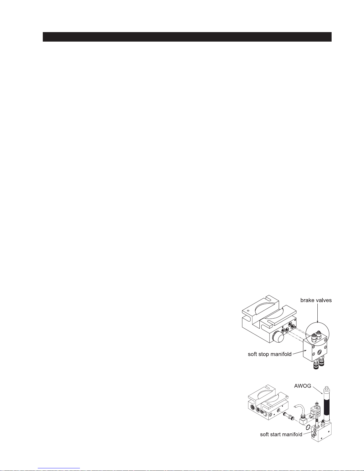
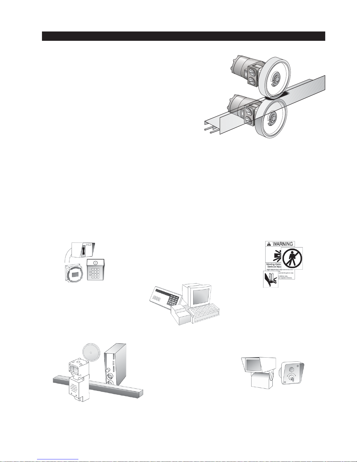
Stopping the Gate
All models employ a time delay Soft Stop system. Additionally,
optional brake valves (shown at right) are used to control the
stopping of heavy or fast moving gates. These valves are exclusive to Hy-Security operators. They are independently adjustable
to allow the gate to stop predictably and without banging.
Starting the Gate
When starting very heavy gates to accelerate faster than one foot
per second, it is necessary to Soft Start the load gently, in addition
to stopping it smoothly. Hy-Security accomplishes Soft Start with
another exclusive feature we call an AWOG, which diverts some of
the start-up hydraulic flow and thereby allows the gate to accelerate over a period of about 2 seconds. This is much like letting your
foot slowly off a car clutch - no lurching when the gate starts. The
AWOG definitely improves the life and performance of a gate
system and never needs adjustment.
1
Page 8

Installation and Maintenance Manual
Available Models and Features
Operators for Heavy Gates: E Models
Models 222 E, 333 E, 222 CE and 222 DE differ from the base model only by the addition of a
hydraulic manifold with two adjustable brake valves, shown on the previous page. The brake valves
extend the maximum weight capacity from 1,000 pounds to up to a 4,000-pound gate. Brake valves
are highly recommended for heavy-duty applications.
High Speed Operators: EX Modes (UL class III and IV only)
The AWOG soft starting system and the brake valves are keys to smoothly moving gates faster than
one foot per second. These devices, together with our hydraulic drive, create smooth and predictable handling for both small lightweight or large heavy gates. The 222 EX, CX, and DX models also
employ larger drive wheels and a higher flow rate pump to achieve a speed of 2.0 feet per second.
DC 24-Volt UPS (Un-interruptible Power Supply) Operators
These gate operators function from 24 Volts DC Batteries all of the time to achieve a true UPS
system. Our Un-interruptible Power Supply is the most certain way to know that your gate will work
when the local AC power fails. This system features fully sealed maintenance free batteries in a
separate insulated and ventilated enclosure. A two-battery version provides at least 3,000 feet of
backup gate travel. A four-battery version provides at least 8,000 feet of backup travel during local
power loss.
“CF” Correctional Facility Operators
The CF models offer an extra heavy 10-gage cover with three different locking options. Type CF
operators are shipped ready to interface to the many options and interlocks commonly used at
correctional facilities, such as gate position outputs, interlock capability for sally ports and an interface relay to control an external solenoid lock.
333 Modular Operators
The family of 333 type operators is a two part modular version of the standard 222 operator. The
motor, hydraulic pump and electric controls are located in a separate enclosure from the drive unit.
This version allows for a more flexible placement of the operator, which may be required or desirable
in some situations involving unique mounting, special security or those wanting a very quiet operator. (When the hydraulic controller is mounted at a distance)
444 Super Powerful Operators
The 444 type operators are for heavier gates, weighing up to 20,000 lbs. They employ a much
larger chassis with four drive wheels and hydraulic motors, and a five horsepower electric motor to
generate up to 1200 pounds of draw bar pull.
The Smart Touch Controller
This is the brain of Hy-Security’s automatic operators. Truly high technology, but also very rugged to
reliably serve in the harshest environments. The Smart Touch Controller can quickly be configured
by an installer or user to adapt to about any functional requirement for a specific site. All system
settings are performed with the use of just four programming buttons and an LCD display. The
Smart Touch Controller has no switches of any type to set. An RS232 port for external communication is standard. A real time clock and an EEPROM record system events. With optional software, a
log of events can be downloaded from the RS232 port. Vehicle detector modules will set a new
industry standard by communicating a host of valuable performance data to the main Smart Touch
controller via a serial data stream, allowing user-friendly diagnostics.
2
Page 9
Installation and Maintenance Manual
READ THIS FIRST!
Important Information - Review Before Installation
Automatic gate operators provide convenience and security to users. However, because these
machines can produce high levels of force it is important that all gate operator system designers,
installers and end users be aware of the potential hazards associated with improperly designed,
installed or maintained systems. Keep in mind that the gate operator is only one component of the
total gate operating system. It is the joint responsibility of the specifier, designer, purchaser, installer and end user to verify that the total system is appropriately configured for its intended use.
All parties should be informed that entrapment in a moving gate could cause serious injury or death.
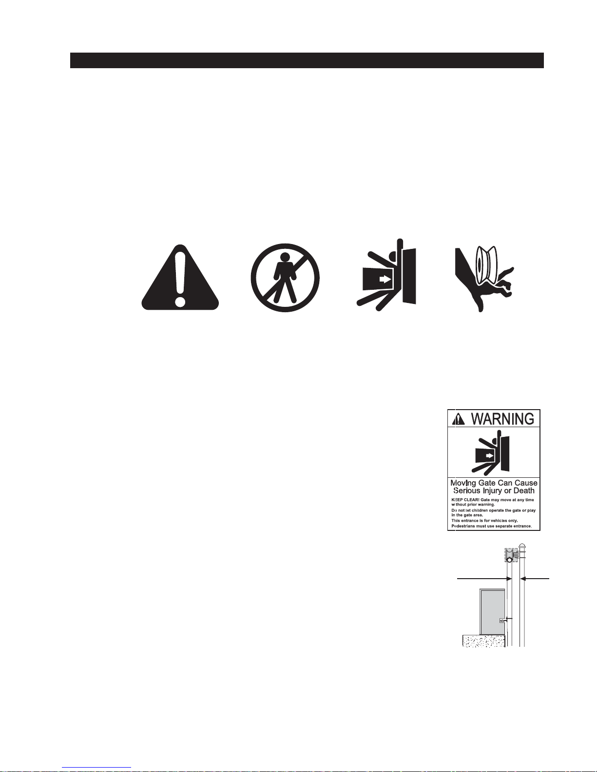
Common
Industry
Symbols
Important Instructions for Gate System Designers & Installers:
WARNING: To reduce the risk of serious injury or death, read and
follow all instructions in the gate operator handbook and on the
warning labels.
Install an Automatic Gate Operator only When:
• The entry is configured for vehicular use only. Pedestrians must be directed to a separate walk-through entrance. The Warning signs that have
been supplied with this operator must be installed, in manner clearly
visible, in the area of both sides of the gate.
• All openings of a horizontal slide gate are guarded or screened, from the
bottom of the gate to a minimum of 4 feet (1.2 m) height above the
ground, to prevent a sphere 2 1/4 inches (57 mm) in diameter from passing through an opening anywhere in the gate or the portion of the adjacent
fence that is covered in the open position.
• All exposed pinch points, rollers and wheels are guarded. To reduce the
risk of entrapment, the gate must also be installed so that enough clearance is provided between the gate and adjacent structures both when
opening and closing. Minimize the parallel gap between the gate and the
fence.
minimize
gap
• The gate has been constructed with physical stops to prevent over-travel
in both directions and has guard posts that prevent the gate from falling in
the event of a roller failure.
3
Page 10
Installation and Maintenance Manual
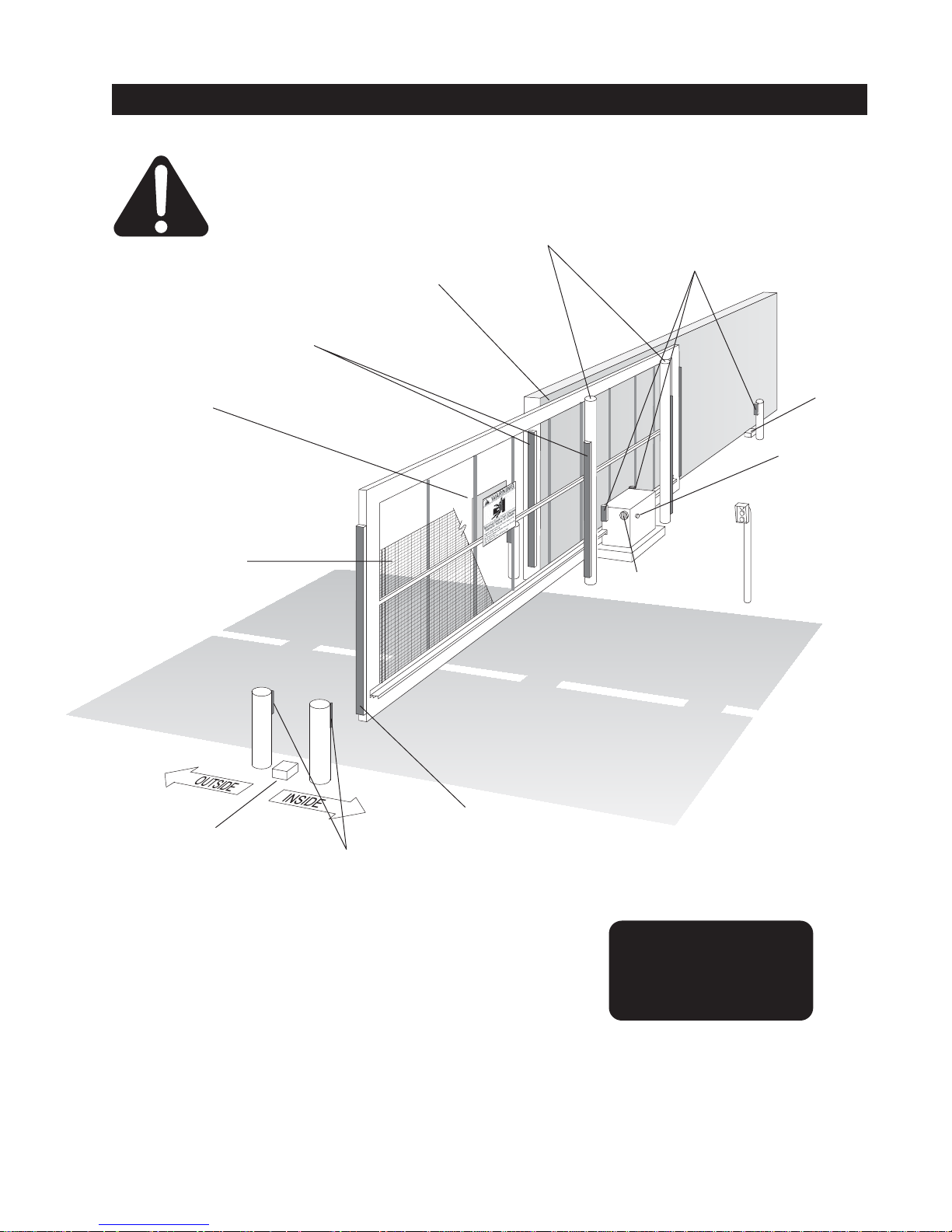
Entrapment Protection Device Schematic for Sliding Gates
Attention
Warning signs must be
on both sides
2" safety mesh
prevents reachthrough: height not
less than 48 inches
Gate edge
sensors
Keep this gap as
small as possible
Guard posts
Photo Eyes for
both directions
Physical travel
stop, both ends
Stop and reset
button
Access controls at
least six feetaway
from gateand
operator
Audio alarm
Physical travel
stop, both ends
Photo Eyes for
both directions
each side of gate
This schematic view is not meant to recommend the only way to set up your configuration, but to
point out the various elements of a proper automatic vehicular gate installation. The gate operator
itself is only one component in the total system. Always install a separate pedestrian gate.
Gate edge sensor, on
leading edge and
trailing edge
Note: All wheels must
be covered. (Wheels
and covers not shown
for clarity)
4
Page 11

Installation and Maintenance Manual
Install An Automatic Sliding Gate Operator Only When:
• The gate moves freely in both directions. Never over-tighten a clutch or pressure relief valve to
compensate for a stiff gate.
• The operator will be installed on the secured (non-public) side of the gate.
• The operator will be properly electrically grounded and the intended supply voltage matches the
voltage label on the operator.
• The controls that operate the gate have been mounted far enough away from the moving gate
such that users cannot touch the gate while operating the controls. All easily accessible controls
must have a security feature to prevent unauthorized use.
• The operator controls will be located in a clear line-of-sight to the gate. Radio controls and other
remote access controls must be connected only to the Remote Open input.
• The required external entrapment sensors will be installed. Be certain to carefully review the
instructions for placement, installation and adjustment of these external entrapment sensors.
External entrapment sensors must function to reverse the movement of the gate in both the
opening and closing directions. If edge (contact) sensors are used, they are to be mounted on
the leading edge, trailing edge of the gate, as well as post mounted on the inside and outside of
the gate (See figure on page 4). If photo eyes or other non-contact sensors are used, they are to
be mounted in locations most likely to guard against entrapment. A combination of contact and
non-contact sensors may be used, but all must be recognized components under the UL 325
standard. See pages 31 and 32 for details on the requirements.
• If the Entrapment protection is provided by a continuous pressure actuation control, a placard
stating “WARNING” - “Moving Gate has the Potential of Inflicting Injury or Death - Do Not Start
Gate Unless Path is Clear.” Additionally, no other activation device shall be connected and an
automatic closing device of any kind shall not be used.
• The automatic operator is labeled as appropriate for both the type and UL usage class of the
gate. Note: Sliding gate operators installed in Class I & II applications must not move the gate
faster than one foot per second.
Class I: Intended to serve single to four family residential uses
Class II: Multi-family use, or any application intended to serve the general public
Class III: Commercial applications not intended to serve the general public
Class IV: Highest security. Security personnel prevent unauthorized access
• Sliding gate operators installed in Class III & IV applications do not have a speed restriction and
the secondary entrapment sensor requirement is met if the system is configured as described for
Class I & II use, or by the following alternate means: Employ the use of a 100dB buzzer, which
sounds at least 3 seconds before the gate moves, and/or functions only by use of a constant
hold type push button control
5
Page 12

Installation and Maintenance Manual
Important Information For Gate System Owners & Users
WARNING: To reduce the risk of serious injury or death, read and follow all instructions in
the gate operator handbook and on the warning labels.
Save These Important Owner and User Instructions:
(Installers - be certain to instruct the owners and users about the following items)
• Automatic gates are for vehicular use only! Provide walkways and signs to direct pedestrians to
a separate walk-through entrance. Because an automatic gate can start at any time without
warning, always keep people away from the area of the gate. The Warning signs that have been
supplied with this operator must remain installed, in manner clearly visible, in the area of both
sides of the gate.
• Never allow children to use or play with controls that operate the gate. Keep all remote controls,
especially radio transmitters, away from children.
• Teach all users how to turn off the electric power and how to release and move the gate manually. Use the manual release only when the gate is not moving.
• Test the function of the gate operator monthly. The gate MUST reverse its direction of travel
upon contact with a rigid object, and/or stop upon a sensing a 2nd sequential activation prior to
reaching a full travel limit. Also test for the normal function of any non-contact sensors. If the
gate system employs the use of a transmitting edge sensor, be especially certain to test and
replace its battery on a routine basis.
• KEEP AUTOMATIC GATES PROPERLY MAINTAINED. Have a professional gate installer
perform routine tests of the entrapment protection sensors, such as photo eyes and gate edges.
Also, make all necessary repairs to the gate hardware to keep the gate running smoothly. Failure to adjust and test a gate operator properly can increase the risk of injury or death.
• In addition to appropriately placed external entrapment sensors, ask your installer to reduce the
setting of the pressure relief valve to the lowest setting allowable that reliably operates the gate.
This valve controls the force of the operator, and the sensitivity of the inherent reversing sensor.
• Do not attempt disable or muffle the Warn Before Operate buzzer, except in class IV
restricted access locations. This buzzer provides an alert that the gate is about to move.
6
Page 13
Installation and Maintenance Manual
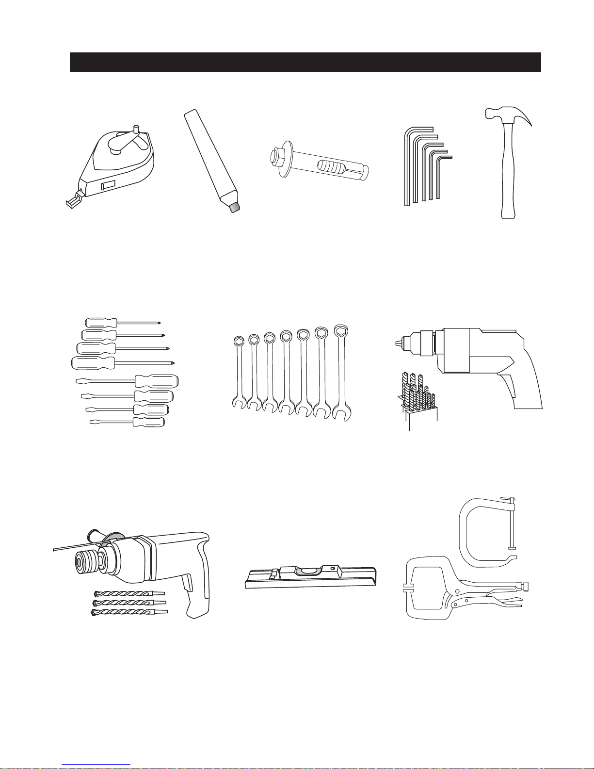
Tools Required for an Efficient Installation
1. chalkline or other
builders string
6. screwdriver sets,
Straight and Phillips
2. carpenters
pencil or crayon
7. wrench set, open
end,
3. concrete anchor
bolts - four
1
/4" through 1"
1
/2" x 4
4. allen wrench set 5. hammer
8. electric drill and
bits 1/8" through 3/8"
9. roto-hammer and
3
/8" through 1/2"
bits,
10. level - it doesn't
have to look like this
one, but the installation
needs to be level!
7
11. Two pair wide
jaw vice grip pliers,
or two C clamps,
4" capacity
Page 14
Installation and Maintenance Manual
Getting Started with an Automated Gate System
• How our hydraulic operator works
Hy-Security industrial slide gate operators rotate
polyurethane treaded drive wheels which grip a rigid
metal drive rail and feed it right or left during the gate
travel. The drive wheels are clamped above and below
the drive rail and are directly coupled to powerful
hydraulic motors, which can easily move huge gates.
This simple yet durable drive system is one of the
unique features giving our hydraulic operators their
reputation for reliability.
• Accessory Compatibility
Hy-Security’s Hydraulic Slide Operators are fully compatible with all standard access control devices and entrapment protection devices, some of which are listed below.
• Pedestrian Entrapment Protection
Read and understand all the Important Information in Section 1, the Entrapment Protection Schematic on page 4 and the UL requirements on page 31 before beginning the installation. Be absolutely certain that the required type and quantity of Entrapment Protection devices have been
supplied and that you understand how to install them correctly. Contact your local distributor with
questions about Entrapment Protection.
Basic Access Control
Radio Transmitter
Long Distance Control
Pushbutton Control Station
Programmable Time Clock
Card Reader
Obstruction Sensing Devices
Inherent Sensing Device
Gate Edges
Photo Eyes
Vehicle Detectors
Information
Signs
Labels
Warnings
Advanced Access Control
Access Control Interface
Card Reader
Keypad
Telephone Entry
Input/Output
Computer Interface RS232/485
Security
Key Locks
Closed Circuit Television
Gate Position Indicator
Interlock/Sally Port
Gate Status Indicator
8
Page 15
Installation and Maintenance Manual
Remember to
cover all four of
the cantilever
gate wheels
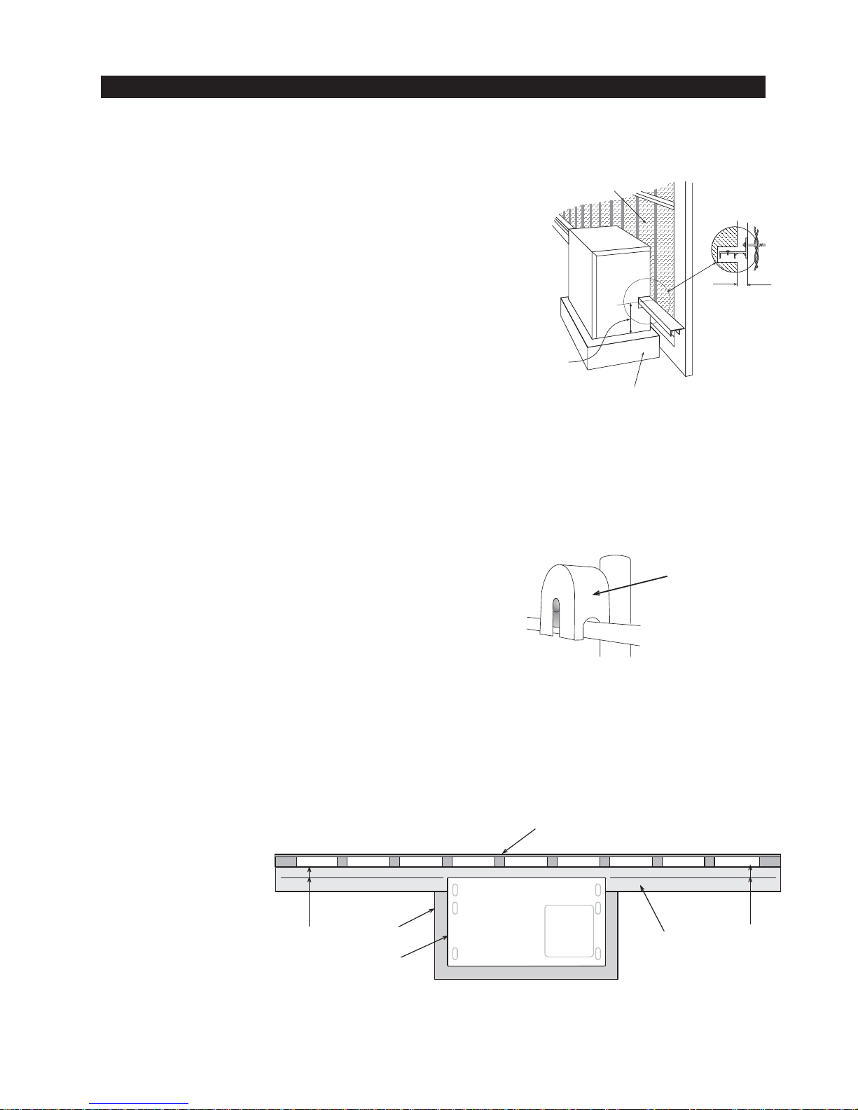
Installation Preparation Checklist
1. Read all of the instructions, especially the Important
Information in Section 1 at the beginning of this
manual, before you attempt installation. This section is
focused upon mechanical installation. For electrical
setup, refer to Section 3, on system configuration and
safety mesh to prevent
reach-through
use of the Smart Touch Controller.
2. Check to see that the mounting slab is the recommended size and ready to have an operator attached.
Also check that electrical conduits are correctly located
to enter the chassis. Hy-Security recommends a slab
reaches below the local frost line and extends somewhat above grade. See the footprint plan and elevation
view on pages 14 & 15.
Drive rail
location:
3
9
/4" from top
of slab to top of
drive rail
concrete slab
3. Make sure the gate rolls smoothly in both directions, without any binding of the gate hardware. If the
gate is warped or hard to move, stop and fix the gate before attempting to automate.
Figure A
Gate distance
from operator:
3
/4" back of
1
drive rail to edge
of operator
4. Verify that you have covers for all exposed gate support
wheels. These must be installed. Also, look around to
identify all of the potential pinch points and hazardous areas,
Figure B
and plan the best location for the entrapment protection
devices and warning signs. Remember that you are required to advise the owner regarding the potential hazards
of an automatic gate and about the function of the entrapment protection sensors that you have selected and installed.
5. There are 3 steps to a perfect inst all: location, location, location. One of the most critical adjustments in installation will be to make sure the operator is located the proper distance from the gate,
and that the gate and operator are as parallel as possible. See Figure C below . Prepare some
shims for aligning the drive rail.
fence
Figure C
Note: If necessary, shim the drive rail so that it is straight 1/4" throughout the travel distance of
the gate.
3
1
/4"
slab
drive rail
operator
3
1
/4"
9
Page 16
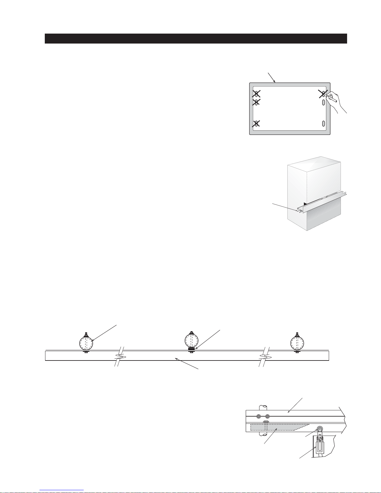
Installation
1. Drill four holes for concrete anchors
Each operator comes with a paper template with the anchor
slots. Place the template on the slab; making sure that it is
parallel to and 1 3/4" from the gate. Trace the slots, remove the
template, and then scribe the locations for your anchor bolts.
Drill holes for the anchor bolts in the center of the slots you
marked, so that you will have some room for adjustment. There
are six mounting slots in the chassis, install at least four 1/2 “ x
4” concrete anchor bolts, using two per side.
2. Line up the operator
Put the operator in position onto the anchor bolts. Verify that the
operator is parallel and 1 3/4" away from the gate on both the left
and right sides, and then tighten the anchors securely.
Installation and Maintenance Manual
slab
3. Two part Operators (battery models and 333 modular
models)
These two part operators come with a separate enclosure, which
Roll pins line
up drive rail
segments to
assure perfect
splicing
should be mounted within 10 feet of the operator, but not more
than 100 feet. We recommend wall mounting or using two 4"
posts, with horizontal mounting strut to create a support for this
enclosure.
4. Bolt the Drive Rail to the Gate Panel
Connect multiple sections of drive rail together with 1/4" roll pins for a perfect splice. The drive rail
must be bolted to each vertical member of the gate panel. This may be done with U-bolt clamps or
through bolts, however U-bolt clamps allow for easy up down adjustment. If the gate is bent or
warped, shim the drive rail so that it is straight ± 1/4" throughout the travel of the gate. When the
drive rail has been installed at the correct height, the top surface is 9 3/4" above the operator base.
A label on each side of the operator indicates the correct height.
fencepost shim as necessary
5. Install Limit Ramps on Underside of Drive Rail
Push the gate to the fully closed position and drill a 3/8" hole in
through the drive rail to mount a 12" plastic limit ramp under the
drive rail, in the wheel channel, at a location that will trip the
limit switch approx. 6" before the exact spot you want the gate
to stop. Adjust the lever arms on the limit switch so that the
roller clears the underside of the drive rail by at least 1/4 inch.
Push the gate fully open and repeat this procedure with the
other limit ramp. See the Drive Rail drawing S22 on page 16.
drive rail
drive rail
limit roller
limit ramp
limit switch
10
Page 17
Installation and Maintenance Manual
OFF
POWER
ON
manual
release
verify 2" when
engaged
Installation
6. Install Grip Tape to Underside of Drive Rail
Two pieces of grip tape have been provided that should be installed on the underside of the drive
rail. Place the tape on the first and last 2 ft. of travel, just in front of each limit ramp. Be certain the
drive rail is clean and dry, and then peel off just a bit of the backing to expose only about 2" of the
adhesive. Attach the tape to the underside of the drive rail, within 1" of the front of the limit ramp.
Now that the tape is lined up, peel the remainder of the backing away and attach the full length of
the tape. Repeat this procedure for the other end of the drive rail.
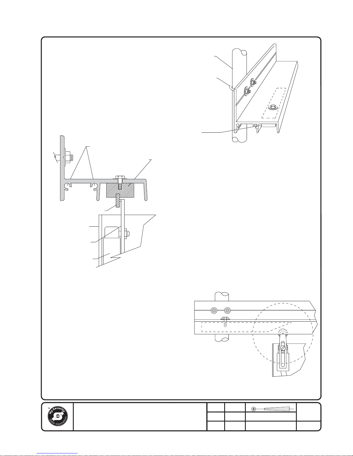
7. Clamp the Drive Wheels to the Drive Rail
When the wheels are fully clamped on the drive rail, the
red spring should be compressed to 2" in height. If
adjustment is necessary, turn the nut at the bottom of the
threaded rod assembly. Slightly less compression is okay
for lighter gates. See Use of Manual Release on page 54
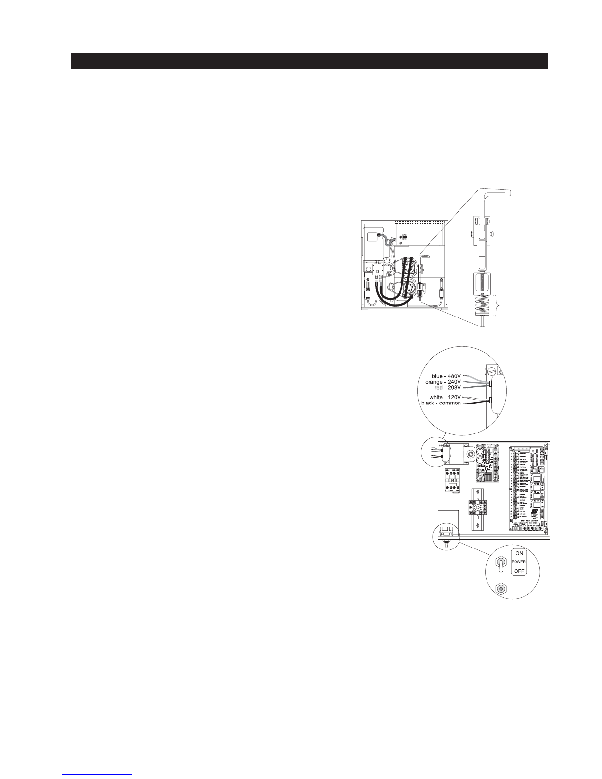
8. Electrical Power Connection
This operator is intended for permanent installation, so all
electrical conduits must be properly connected to the
control box. The entry for the primary power is a 1/2 - 3/4"
knockout on the left side of our control box next to the on-off
switch. When this operator was manufactured, it was built to
run on a specific voltage and phase for line power. Make sure
you have compared the line voltage and phase available with
the nameplate on this machine. They must match! Be certain
that the wire size of the branch circuit that will supply the operator vs. the distance of the run from the main panel is large
enough to avoid excess voltage drop. Also be sure the operator
is electrically well grounded. See the Appendix, page 63 for
correct wire sizes and detailed electrical wiring information.
9. Primary Tap of Control Transformer
(not on battery operators)
Check to make sure that the primary tap on the control transformer matches the line voltage you have connected to the
operator. Measure the line voltage carefully to distinguish between 208V and 230V branch circuits. A label on top of the
transformer identifies the various voltage taps.
power
connection
on/off switch
stop/reset
P
R
R
E
E
K
S
A
S
E
T
R
O
B
R
T
I
E
U
S
C
E
R
I
T
C
control
transformer
primary taps
RUN
RELAY
15 AMP
PROGRAMMABLE
USER RELAY
15 AMP
PROGRAMMABLE
USER RELAY
15 AMP
PROGRAMMABLE
USER RELAY
10. Electrical Power for Two Part 333 type operators
The primary AC power must be routed to the controller enclosure with the pump, but there must
also be conduits between the gate operator and the controller enclosure.
Note: AC power is not needed in the gate operator, unless there is an optional heater. A minimum
of two separate conduits must be provided, 2" for the hydraulic hoses and 3/4" for the electrical
interconnections. Unless there are accessories in the gate operator, the only electrical interconnection between the two enclosures will be three wires between the two terminal strips for the limit
switches. Join the hydraulic hoses by plugging the quick coupling together according to the hand of
the gate. See the drawing in Section 8, page 60.
11
Page 18
Installation and Maintenance Manual
Installation
11. Connections for Two Part Battery Operators
The primary AC power must be routed to the DC power supply enclosure, but there must also be at
least a 1" conduit between the gate operator and the DC supply enclosure. Note: AC power is not
needed in the gate operator enclosure, unless there is an optional heater. Three separate DC
circuits are required between the battery supply and the gate operator. Heavy gage wires to supply
the motor and two 14-gage circuits for the controls. The heavy gage wire must be at least 6-gage if
the DC supply is within 20 feet of the operator, but must be increased to 2-gage if the DC supply is
located farther from the operator, or the this is an EX - 2'/sec model. Also see page 56 titled “Wiring and Control Configuration for DC Operators” and Drawing E125 in Section 8, page 58.
12. Check the “Hand” of the Operator
All slide operators must have their “hand” set
before they can function. The “handing” must
be set both by the proper hydraulic hose
connection and electrically. The hose connection for proper handing is described on a label
near the hose connection point. Also, see the
instructions to set handing on page 18 “Installation Configuration for Smart Touch Controller.” Handing is viewed by standing in the
middle of the road on the inside looking out.
Remove the blue plastic
shipping plug and replace
with black breather cap.
To change hand connect
hoses according to label
on tank.
ON
POWER
OFF
13. Replace the Blue Plug!
Replace the blue plastic shipping plug on the front side of the pump with the black breather cap.
14. Setup Smart Touch Controller
The operator controls will not allow the gate to function until the Smart Touch Controller has been
configured. Wait to connect the external controls until you have reviewed the Smart Touch Controller instructions and tested the basic functions.
Note: Hy-Security has an installation CD available free of charge to installers. Call a Hy-Security
distributor for a copy.
12
Page 19
Installation and Maintenance Manual
OFF
POWER
ON
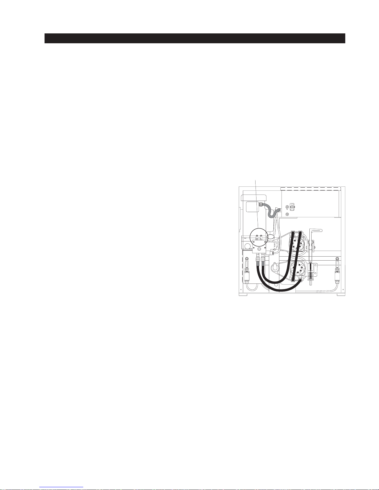
Optional brake valves CCW = quicker stop.
Left valve controls open
Right valve controls close
Mechanical and Hydraulic Adjustments
1. Drive Wheel Spring Tension
When the drive wheels are fully clamped on the rail, the red spring should be compressed to 2" in
height. If adjustment is necessary, turn the nut at the bottom of the threaded rod assembly. Slightly
less compression is okay for lighter gates. (See Figure on page 11, and full details on page 54).
2. Drive Rail
Verify that the drive rail does not vary more than 1" up and down, or 1/4" in and out throughout the
entire horizontal travel of the gate. Re-alignment is simple if the rail is mounted with U bolts. To
adjust in and out, loosen the U bolts and add or remove shim stock. To adjust up or down, loosen
the U bolts and simply tap the rail with a hammer until the correct height is reached. Adjusting the
rail in or out requires inserting shims between the rail and the gate where necessary.
3. Brake Valves (suffix E, EX models only)
If your operator is equipped with brake valves, their proper
adjustment is important for smooth operation of the gate. In
order for the brake valves to have time to function, the limit
ramp must trigger the limit switch at least six inches before
the point at when you want the gate to stop. Adjustment of
the brake valves, one for each direction of travel, will determine how quickly the gate actually stops. If adjustment is
needed, loosen the 9/16" lock nut on the top of the brake
valve and turn the adjustment stem, in about 1/4 turn increments, with an Allen wrench. The adjustment works opposite
of typical, such that a counter-clockwise adjustment will stop
the gate more rapidly. If the adjustment is set too loose, the
limit ramps will bang into the drive wheels. If the adjustment
is set too tight, the system pressure will increase, the gate
speed may decrease and the gate will jerk to a stop. Set the
brake valve to achieve a controlled smooth stop, and then
retighten the locking nut to hold the setting.
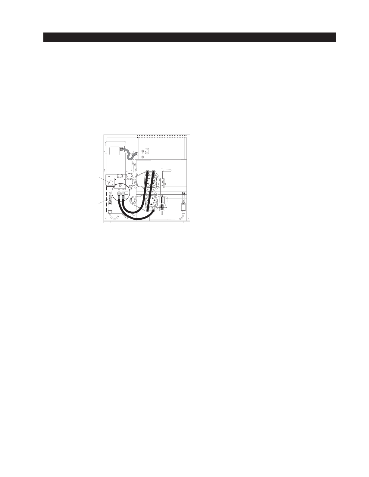
4. Pressure Relief Valve
This valve, which governs the maximum system hydraulic pressure available, is located on the
backside of the pump, just above the limit switch. Installers are encouraged to reduce the relief
valve setting to the lowest pressure that will reliably operate the gate. A lower setting reduces the
maximum force that the gate operator can exert. If adjustment is needed, loosen the 9/16" lock nut
and turn the adjustment stem with a wrench. Lower pressure (force) is achieved by turning the
adjuster stem counter-clockwise. The only way to display the actual relief valve setting is to unplug
the hydraulic hoses from the quick disconnect fittings. Be certain to retighten the locking nut to
hold the desired setting and reconnect the hoses correctly. Also see the drawing in Section 7, page
52 for the location and a schedule of factory pressure relief settings.
5. Directional and Quick Stop Valves
These two valves are solenoid operated. The directional valve is below the motor near the front of
the pump and energizes in order to direct the hydraulic flow to open the gate. The quick stop valve,
which is near the back of the pump energizes at the beginning of a cycle to allow no load motor
starts and at the end of each cycle to aid in decelerating the gate. No adjustment of these valves is
possible or ever needed.
13
Page 20
Installation and Maintenance Manual
NOTE: COVERS MUST BE USED FOR
PROTECTION ON ALL EXPOSED WHEELS
AND/OR HARDWARE. COVERS ARE SHOWN
HERE AS DOTTED LINES.
ON
POWER
OFF
NOTE: SEE DWG# S13B
FOR RECOMMENDED SLAB
DIMENSIONS.
NOTE: DRIVE RAIL HEIGHT
IS MARKED ON THE SIDE
OF EACH CHASSIS.
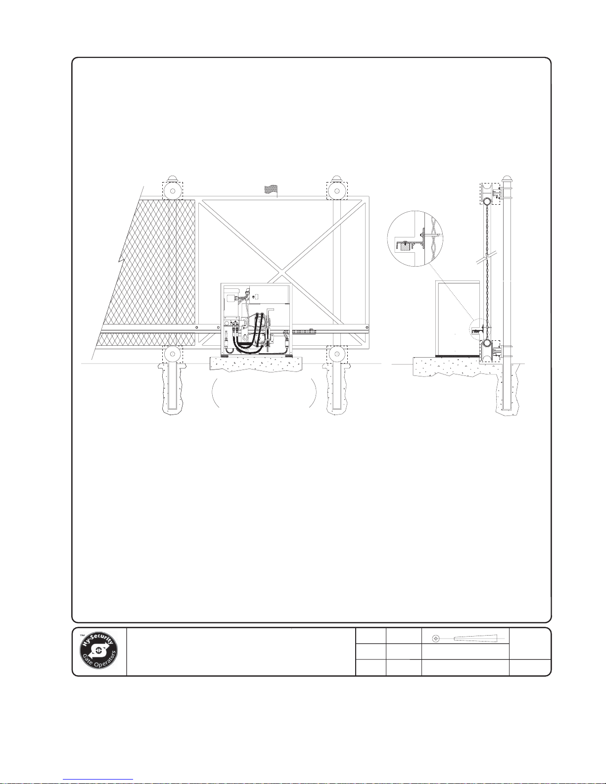
seattle, washington
RIGHT HAND CANTILEVER GATE IS
SHOWN IN THE FULLY CLOSED POSITION.
OPERATOR COVER OMITTED FOR DETAIL.
( DO NOT SCALE )
NOTE: CONSULT FENCE CONTRACTOR
FOR RECOMMENDED CANTILEVER POST
SPACING. 50% OF GATE OPENING
GENERALLY PROVIDES SMOOTH OPERATION.
TITLE
Typical Slide Gate Operator with
R.H. Cantilever Gate Panel
SECTIONELEVATION
NOTE: IT MAY BE NECESSARY TO
SHIM DRIVE RAIL IF GATE PANEL
IS "BOWED". RAIL MUST BE INSTALLED
IN A STRAIGHT LINE.
KERI
CHECKED
SHOP
APPROVED
ENGRNG
DATE
4/20/00
DATE
MM/YY/DD
DATE
MM/YY/DD
THIRD ANGLE PROJECTION REVDRAWN
PART NUMBER
N/A
DRAWING NUMBER:
S13A
--
SHT OF
1 1
14
Page 21
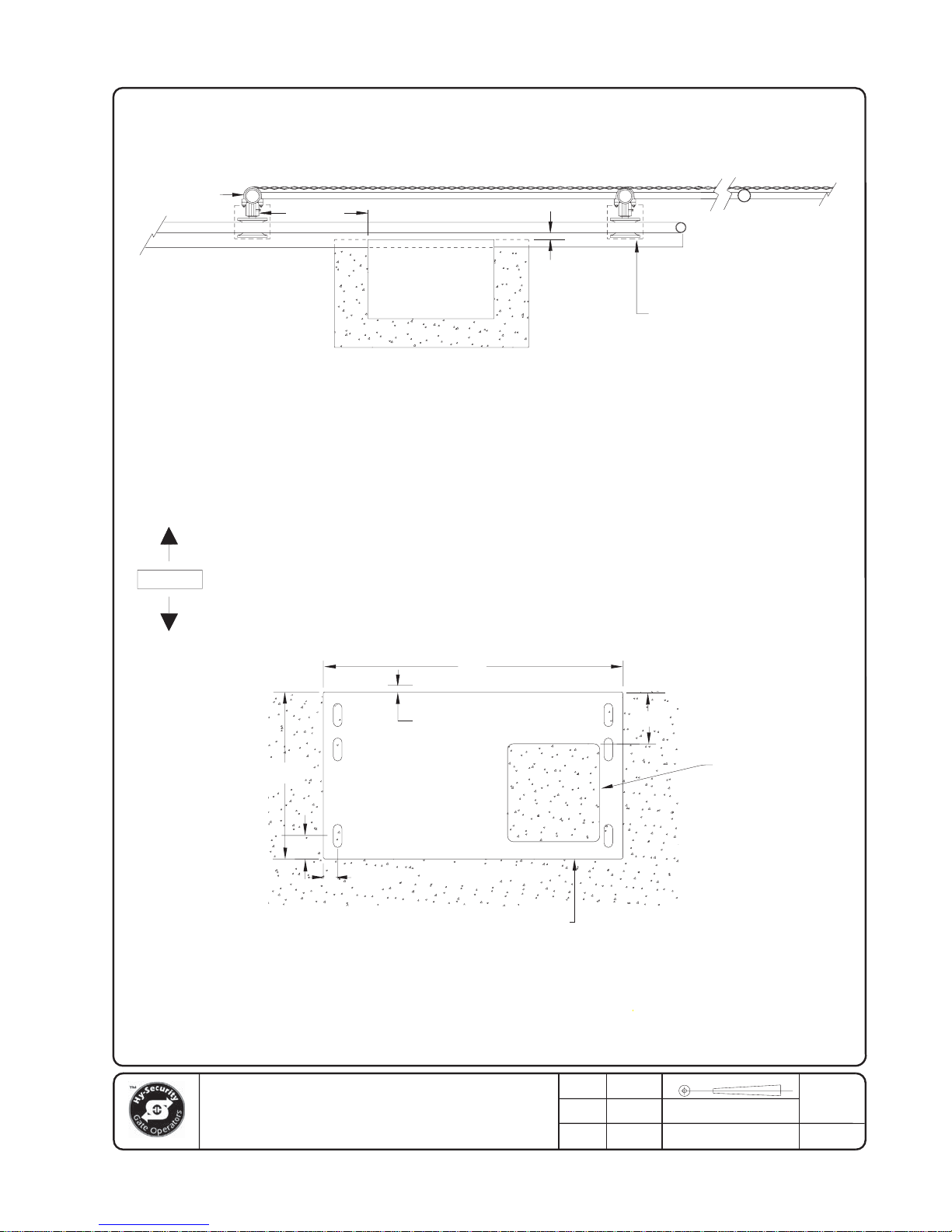
FENCE LINE
Installation and Maintenance Manual
GATE POST
GATE PANEL WITH
DRIVE RAIL ATTACHED
ROADWAY
ALLOW
12" TO 16"
GATE
OPERATOR
1-3/4"
NOTE: CANTILEVER WHEELS MUST
BE COVERED TO HELP PREVENT
INJURIES. COVERS SHOWN HERE
IN DOTTED LINES.
NOTE:
MINIMUM CONCRETE SLAB DIMENSIONS RECOMMENDED ARE:
30"WIDE, 20" FROM FRONT TO BACK AND 16" DEEP.
CHECK LOCAL FROST CONDITIONS AND SOIL CHARACTERISTICS
FOR EXACT REQUIREMENTS IN YOUR AREA.
OPERATOR IS INSTALLED ON A CONCRETE PAD AND CONNECTED
TO THE RIGHT HAND CANTILEVER GATE PANEL. 4" POSTS ARE
SHOWN FOR GATE SUPPORT AND FENCE TERMINATION.
DIMENSIONS OF OPERATOR AND BASE
( FENCE/GATE SIDE)
26"
seattle, washington
14½"
MINIMUM OF FOUR
ANCHOR BOLTS REQD.
½" X 4" OR
THIS TEMPLATE IS FOR
BOTH RIGHT AND LEFT
OPERATOR.
2"C/L
1-¼"C/L
OPERATOR BASE ¼" PLATE, PLAN VIEW
NOTE:
CONTACT A FENCE CONTRACTOR FOR EXACT SPACING ON CANTILEVER POSTS.
50% OF OPENING WIDTH GENERALLY PROVIDES A SMOOTH OPERATION.
TITLE
Slide Gate Operator (typ) R.H.
Cantilever Gate Panel
1-3/4" TO FACE
OF GATE
½" X 6"
( SECURE OR INSIDE )
KERI
CHECKED
SHOP
APPROVED
ENGRNG
5"
DATE
6/12/00
DATE
MM/YY/DD
DATE
MM/YY/DD
ELECTRICAL
ACCESS
8½" X 8"
THIRD ANGLE PROJECTION REVDRAWN
PART NUMBER
N/A
DRAWING NUMBER:
S13B
B
SHT OF
1 1
15
Page 22
Installation and Maintenance Manual
KEYWAYS FOR SPLICE PINS
LIMIT SWITCH RAMP
LIMIT SWITCH WHEEL
OPERATOR
VERTICAL GATE
MEMBER
"U" BOLTS
LIMIT
SWITCH
RAMP
SECTION THROUGH DRIVE RAIL AND
LIMIT SWITCH SHOWING RELATIONSHIP
OF SWITCH, LIMIT RAMP AND DRIVE RAIL.
LIMIT SWITCH
ARM
LIMIT SWITCH
BODY
SIDE VIEW OF LIMIT RAMP AND LIMIT SWITCH
IN OPERATION. TAPERED ENDS, ALWAYS POINT
TOWARD THE OPERATOR DRIVE WHEELS.
NOTE: ALUMINUM RAIL SHOWN, STEEL RAIL SIMILAR.
TITLE
Drive Rail Slide Gate Operation
seattle, washington
KERI
CHECKED
SHOP
APPROVED
ENGRNG
DRIVE RAIL
LIMIT RAMP
DATE
6/12/00
DATE
MM/YY/DD
DATE
MM/YY/DD
THIRD ANGLE PROJECTION REVDRAWN
PART NUMBER
N/A
DRAWING NUMBER:
S22
SHT OF
1 1
16
Page 23

Installation and Maintenance Manual
Basics of Using the Smart Touch Controller System
Read this page if you are unfamiliar with using the Smart Touch Controller.
You must learn to navigate and change menu settings within the Smart Touch Controller before an
installation can be completed or any control settings or function changes can be made.
Until a new operator has been configured, the controls are not functional and the display is
locked in the menu mode until the User Class 1-4, and Left or Right hand use have been
selected. See the next page for instructions on how make these settings.
1. There are five buttons on the membrane switch pad that provide
control of everything. The Open, Close and S top buttons serve as a
three-button control station, but in the Menu Mode, they become Previous, Next and Select buttons. The Program Menu button is used to
both enter and exit the Menu Mode. The Reset button clears all Errors
and Faults that may occur and returns the control to its normal functioning state.
2. When in a Menu Mode, changes to be made to a Menu setting are
accomplished by pressing the Previous, Next and Select buttons in the
following sequence:
a. Press the Next button to move forward through the list of menu
items that are available, as shown on pages 22 and 23, or press
the Previous button to move back to an item that you recently passed.
b. Press the Select button if you wish to make a setting change to a menu item. The menu item will
flash to indicate that its setting is ready to be changed.
c. Press Next to move forward or Previous to go back to an earlier setting choice.
d. When you have located the setting that you want to use, press the Select button and the pro-
gram will accept the change and stop blinking.
e. The Program Menu button does not allow an exit to Run Mode while a selection is still blinking.
Press the Select button to stop the blinking, then you may exit to Run Mode.
f. Pressing the Next or Previous buttons when the menu item is not blinking will move to the next or
previous menu item.
g. When done, press Program Menu to exit to the Run Mode.
3. Once configured, the operator will be in the Run Mode. From the Run Mode, to gain access the
User Menu or the Installer Menu, follow these steps:
a. Note that the Program Menu button will not function unless the gate is at rest and no open or
close inputs are active. V erify system status by pressing the LED button to disclose any active
inputs. There also must not be any Alert s, Fault s or Errors. Press the Reset button to clear the
system if necessary .
17
Page 24

Installation and Maintenance Manual
b. Press the Program Menu button and watch the LCD scroll the system data, or press the Pro-
gram Menu key a 2nd time to skip the scroll. The scrolled data displays the information in the
table on page 22.
c. The LCD display scroll will stop at the menu item for the automatic close timer setting [Ct __].
This is the first item in the User Menu.
d. To access the more detailed Installer Menu, the system must first be in the User Menu, and then
simultaneously press the Reset button and the Open button. The LCD will change to display the
UL usage class menu item [uC __] This is the first item in the Inst aller Menu.
4. Pressing the Program Menu button when the User or Installer Menu is not blinking will return the
system to the Run Mode.
Installation Configuration for Smart Touch Controller
Setting Operator Handing and Usage Class
1. Connect the hydraulic hoses to the quick couplers on the pump in order to configure left or right hand
opening function (as viewed from the secured side of the gate). There is a label near the connection
point describing this procedure. Also see the illustration on p age 12. If the hoses are connected
incorrectly , the gate will run backwards (close when open button is activated) and this may trigger an
error [Err 1] on the LCD display. (The Reset button must be pushed if this happens).
2. Turn on the power switch and observe that the LCD will first show the sof tware version, and then stop
at a steady display within two seconds. If the display reads [uC 0] go to step 3. If the operator has
previously been configured, the Installer Menu must be accessed in order to reach the system configuration menu items: see step #3d at the top of this page.
3. When turning on the power for a new machine, the LCD display directly enters the Installer Menu at the
[uC __] menu item, which is for selecting the user class as defined by UL. Select [uC 1] - [uC 2] [uC 3] or [uC 4] depending upon the use application. See Section 4, page on page 31, for UL usage
class definitions.
4. To set the operator handing, use the “Next” button and move one click down the menu to item [Sh __]
Enter r for right hand or L for a gate that opens to the left. Never alter the limit switch mounting or
change the order of their connection to the controller board. At this point you should exit the Installer
Menu, by pressing the Program Menu button. The LCD display jumps to the close timer [Ct__] setting
in the User menu, which may now be set. Either press the Program Menu button again to exit to
normal run mode or set the close timer by the same programming sequence described at the previous
page.
5. Note that the Installer menu cannot be exited by any means until the selection for UL usage
class [uC __] and the selection for gate handing [Sh __] have been entered.
6. Test for normal function of the gate operator, with the wheels unclamped, by running it both open and
closed from the pushbuttons on the membrane switch pad. Neither limit switch should be triggered at
the start of this test or an alert [ALE6] may trigger because the control did not sense gate motion. If
this occurs a new input will restart the motor .
18
Page 25

Installation and Maintenance Manual
Wiring Control Inputs to the Smart Touch Controller
1. Test the basic open and close operator function before wiring the external control inputs. This makes it
easier to troubleshoot if an unexpected function issue arises.
2. Each input has an LED to indicate when that input is active. To disclose the input status, the LED tact
button must be pushed. This button is in corner near the S top input.
3. All the control device input s listed below are shown as a single input because the other wire is connected the Common Terminal Buss on the Power Supply board. The Emergency Close and Fire Dept.
Open inputs are an exception and require a +24 V olt input in order to be activated. The +24 is available at the spade terminals next to the Common Buss.
Smart Touch Controller Inputs
1) *Stop Push button (N.C. input, jumper to Common if unused)
2) *Open Push Button (not for radio or remote access controls)
3) *Close Push button (not for radio or remote access controls)
4) Remote Open & Radio Control (For radio / remote open device -
menu opt. to also close)
5) Open/Close button (pushbutton or radio controls)
6) Partial Open (installer adjustable from 7- 99 seconds)
7) Open interlock input or Time clock Open (menu configurable)
8) Free Exit vehicle detector
9) Disable Free Exit vehicle detector
10) Inside Obstruction vehicle detector (Inside reversing loop)
11) Outside Obstruction vehicle detector (Outside reversing loop)
12) Shadow/Reset vehicle detector (Shadow is for Swing gates only)
(Reset function is for Arm gates)
13) Edge Sensor (one input works for both directions of travel)
(14-15) Photo eye Common Power (supply for PE power & PE Com)
(17) Photo eye Open direction (spans the gate storage area)
(19) Photo eye Close direction (spans the roadway)
(21) Charger AC power loss (only used in battery type operators)
(22) Spare Input (unused - may have function in custom applications)
(23) *Emergency Close (must menu enable and input +24 Volts to
trigger) Overrides photo eyes, gate edge & vehicle detectors.
(24) *Fire Dept. Open (must menu enable and input +24 Volts to
trigger) Overrides photo eyes & gate edge.
* Do not connect an external control to terminals #1, 2 or 3,
unless the controls are located such that there is a clear
view of the entire gate area. For controls not within sight,
Attention
use input terminals #4, 5, 6 or 7.
*The Emergency Close and Fire Dept. Open inputs are to be used only
if access to these controls are guarded in sufficient manner such that
there is always supervision when activated.
19
Page 26

Press to
disclose
active LEDs
ACCESSORY
POWER
(+)
POWER STATUS
+24 INPUT
GND
MOTOR OVERLOAD
INHERENT SENSER
UNLOAD VALVE
+24V
GND
+24V
OPEN VALVE
RUN N.O.
Installation and Maintenance Manual
RUN COM
Hydraulic Directional
Valve - activates
to OPEN.
Hydraulic Unloading
or Quick Stop Valve
- activates when
starting or stopping.
ACCESSORY DETECTOR ACCESSORY DETECTOR ACCESSORY DETECTOR ACCESSORY DETECTOR
POWER
SUPPLY
BOARD
COMMON
BUSS
(-)
Processor
heartbeat
LED. Blinks at
a regular beat
when normal
RUN
RELAY
15 AMP
PROGRAMMABLE
USER RELAY
15 AMP
PROGRAMMABLE
USER RELAY
15 AMP
PROGRAMMABLE
USER RELAY
8
Clock
Battery
Optional
Hy-Security
HY-5A
Vehicle
Detector
Modules
Limit
Switch
Inputs
Master
Slave
Connection
20
Open
Radio
External
Communication
Port
Gate Edge
Radio
S ICB01Smart Touch Controller - Integrated Circuit Board
Page 27

Installation and Maintenance Manual
Connecting a Master / Slave Pair
Configuring two operators to be a Master & Slave pair is easy with the Smart Touch Controller.
There is no need to order a special model or any adapters. The area of the board marked Dual
Gate employs a 3-wire RS485 serial port for communication between Master & Slave operators.
1. An electrical conduit for the interconnecting wires must sp an between the two operators.
2. Complete the installation of both of the operators as separate machines and verify that their basic
functions are correct as solo operators before interconnecting them.
3. The two gate operators should be supplied by home runs from separate 20 Ampere circuit breakers in
the main panel, but if there is only one circuit, be absolutely certain that the breaker and wire size is
sufficient for the load of two motors. See the Appendix, p age 63.
4. External control inputs, vehicle detectors and entrapment protection sensors may be connected to
either gate operator without regard to preference.
5. To interconnect the two operators, route a shielded twisted pair with an internal ground wire between
the electric control boxes and connect to the RS485 Dual Gate terminals, in matching order on both
machines: In the RS485 shaded area connect the terminals for Master Com to Slave Com with the
ground shield trace wire, and connect the Master A to Slave A and the Master B to Slave B using the
insulated twisted pair of wires.
6. The Installer Menu in each machine must be set as a Master or a Slave under menu item [dg__]. Set
one operator as a Slave [dg_1] and the other as a Master [dg_2]. If the function of any external input is
to be different than the factory default, configure for the desired function on the operator where that
input is connected. Internal functions, such as the close timer or reversal distance, are controlled by
the Master operator regardless of the settings in the Slave.
7. Once set as a Master or a Slave the operators will be in constant communication with each other . If
that communication stops because the wires become severed or one operator is turned off, both
machines will cease functioning and the LCD will display Err4, which is a Master/Slave communication
error. This error cannot be reset until both machines are functional and communicating properly again.
21
Page 28

Installation and Maintenance Manual
Smart Touch Controller User Menu Functions
Initial Power Up - When power is turned on, the display will disclose the software revision:
Display Revision Number 2s delay Displays software version Number , ex. [h3.02]
System Data and accessing the User Menu Settings:
If the gate is stopped in the Run Mode, pressing of the Menu button accesses the User Menu. After
the menu button is pressed, the LCD will scroll the system data in the table below. The scrolling
display stops at the close timer setting, which is the beginning of the User Menu. To exit the Menu
Mode, the display must not be blinking, then simply pressing the Menu button will return the display
to the Run Mode and re-enable the controls. The menu mode will also automatically return to the
Run Mode if there is no activity for two minutes.
Data Displayed in Scroll Time Description
S1 [SLAu] or [LEAd] 2s SLAVE Operator or LEAd Operator (master)
S2 [ot 1] Gate type (1-5) 2s Operator type: 1 =HSG, 2 =HRG , 3 HVG, 4 =HTG
S3 [_rh_] or [_Lh_] Hand setting 2s Displays hand configuration [_rh_] or [_Lh_]
S4 [uC _] UL usage class (1-4) 2s Installer setting of usage class: type 1-4
S5 [d___] 24VDC Buss Volt age 2s Actual VDC buss voltage
S6 [CC__] Life cycle counter 2s High digits of 6 digit life cycle counter
S7 [____] Life cycle counter 2s Last 4 digits of 6 digit life cycle counter
Read through the options available in the User Menu and the Installer Menu on the next page and
you can see that the functions of this gate operator can be configured to suit most any specific
need. Once you have learned to navigate the menus, as described in #2 on page 17, and how to
change a setting, the full range of features and choices of the Smart Touch Controller are available
to use. The User Menu contains the basic configuration items and the Installer Menu contains the
more advanced menu items.
User Menu Options Default Description
U1 [Ct 0] Close timer setting 0 0 = Close timer off or 1 - 99 seconds
U2 [hC 0] Moment ary Close 0 0 = momentary, 1 = Constant hold Close PB required
U3 [ho 0] Moment ary Open 0 0 = momentary, 1= Constant hold Open PB required
U4 [AP 0] Power loss function 0 0 - 3 (0=Type A, 1 = B, 2 = C, 3 = D) See page 56
U5 [ro 0] Radio control option 0 0 = Open only, 1 = Adds close ability when full open
U6 [bF 2] Warn before operate 2 0 =off, 1 = Buzzer alerts 3 seconds before + in motion,
2 =Buzzer alerts 3 secs before + 2 seconds in motion
U7 [FA 0] Forced open Alert and 0 0 = OFF, 1 = sound buzzer (2 pulses/sec) if forced
automatic gate reposition open for more than four seconds, time out in 30 Sec
U8 [dA 0] Drift Closed Alert and 0 0 = OFF, 1 = sound buzzer (2 pulses/sec) if drift
automatic gate reposition closed and cannot reopen within four seconds.
U9 [PE 0] Photo Eye Align Mode 0 0= off, 1 = on (auto off when close limit triggered)
U10 [CL 0] Clock set (24 hour type) 0 0= display, 1= set mins, 2= set hours, 3= day, 4= month
U11 [Ld 5] LCD Contrast set 5 1 - 9 = Adjusts contrast of the display
S1 Appears only if the operator is configured as a master or a slave unit
U1 Close timer setting does not appear when set for constant contact close function
U4 Power loss function only appears if factory has provided DC battery type operator
U6 We strongly advise never disabling the Warn Before Operate buzzer.
These Notes Refer to the Menu Above:
22
Page 29

Installation and Maintenance Manual
Smart Touch Controller Installer Menu Functions
The Installer Menu can be accessed only by entering the User Menu first, and then by pressing the
Reset button and the Open button simultaneously.
To restore the factory default settings, go to menu item [Fd_0] and change the setting to 1,
then press the Program Menu button. The entire menu will reset to the factory defaults.
Installer Menu Options Default Description
I
1 [uC 0] Set UL Usage Class 0 0 = gate disabled, Set Class 1 through 4 use
I
2 [Sh 0] Set Handing of gate 0 0 = gate disabled, r = Right Hand, L = Left Hand
I3 [Fd 0] Load Factory Defaults 0 0 = User settings, 1 = Load defaults (resets full menu)
I4 [dg 0] Set Master/Slave type 0 0 = solo operator, 1 = Slave unit, 2 = Master unit
I
5 [Ch 0] Set AC Charger or Solar 0 0 = DC + AC charger 1 = DC + Solar charger
I6 [Fo 0] Enable Fire Dept. Open 0 0 = disabled, 1 = enabled
I7 [oC 0] Enable Emergency close 0 0 = disabled, 1 = enabled
I8 [SE 3] Inherent Sensor sens. 3 1 = maximum sensitivity, 9 = Lowest sensitivity
I
9 [SS 0] Inherent Sensor function 0 1 = stop only (note, functions in usage class 4 only)
I
10 [LC 0] Leaf delay Close 0 0 = none (1-7) 1/2 second steps (Master/Slave only)
I
11 [Lo 0] Leaf delay Open 0 0 = none (1-7) 1/2 second steps (Master/Slave only)
I12 [rt 0] Maximum run timer 0 0 = 60 Seconds max run, 1 = 300 Seconds max run
I13 [Po 0] Partial Open distance 0 0 = none, or 7 - 99 seconds
I14 [EC 0] PEC reverse to open 0 0 = Close eye stops only, 1 = 2 sec reverse to open
I15 [EO 0] PEO reverse to close 0 0 = Open eye stops only, 1 = 2 sec reverse to close
I16 [gr 0] Edge reverse to open 0 0 = Edge reverses fully open, 1 = 2 sec reversal only
I17 [Sr 1] IES reverse to open 1 0 = IES reverses fully open, 1 = 2 sec reversal only
I18 [PC 0] Set PEO/ PEC - NO/NC 0 0 = Normally Open PE output, 1 = N.C. (supervised)
I19 [gC 0] Set Edge input - NO/NC 0 0 = Normally Open Edge output, 1 = Normally Closed
I20 [tC 1] Time clock/ Interlock input 1 0 = select Time Clock, 1 = select Open Interlock
I21 [or 1] OOLD detector function 1 0 = pause closing only, 1 = enable reversing to open
I22 [ir 1] IOLD detector function 1 0 = pause closing only, 1 = enable reversing to open
I23 [dL 1] Vehicle detector logic 1 1 = std, 2 & 3 = quick close, 4 = full anti-tailgate*
I24 [r1 0] User relay 1 option 1 0 = disabled, 1 - 19 = see output options page 28
I25 [r2 0] User relay 2 option 6 0 = disabled, 1 - 19 = see output options page 28
I26 [r3 0] User relay 3 option 1 0 = disabled, 1 - 19 = see output options page 28
I
27 [t L 0] Gate Open alert 2 0 = 0 sec, 1=15s, 2=45s, 3=75s, 4=105s, 5=135s
I
28 [Lt 0] Loitering alert 3 0 = 0 sec, 1=15s, 2=45s, 3=75s, 4=105s, 5=135s
I29 [ELd0] Test factory ELD* 0 0=Run, 1=show freq, 2=show call level 0-7, 3= set Freq 1-4
I30 [iLd0] Test factory IOLD* 0 0=Run, 1=show freq, 2=show call level 0-7, 3= set Freq 1-4
I31 [oLd0] Test factory OOLD* 0 0=Run, 1=show freq, 2=show call level 0-7, 3= set Freq 1-4
I32 [SLd0] Test factory SLD* 0 0=Run, 1=show freq, 2=show call level 0-7, 3= set Freq 1-4
*See page 43 for description of vehicle detector & Loop Fault diagnostics
These Notes Refer to the Menu Above:
I1,I
2 These settings must be configured or the gate cannot function and menu will not exit.
I
5 These settings appear only if the factory has provided a DC powered gate operator
I9
IES stop only setting [SS __] does not appear unless set as a class 4 operator
I
10,I11 These settings appear only if the Installer Menu is set for Master / Slave function
I
27,I28 These settings appear only if the Installer Menu has set relays r1-r3 for these alerts
23
Page 30

Installation and Maintenance Manual
Description of Functions Available in the User Menu
User 1 [Ct _] Close timer setting: This menu item is the automatic close timer for the gate. The
factory setting is zero, which is off. It may be configured up to 99 seconds.
User 2 [hC 0] Momentary Close: This menu item is to configure for the system for constant hold
push button Close function. The factory setting is zero, which is momentary contact input.
User 3 [ho 0] Momentary Open: This menu item is to configure for the system for constant hold
push button Open function. The factory setting is zero, which is momentary contact input.
User 4 [AP 0] Power loss function: This menu item only appears if the operator is a DC battery
powered version. This item is to configure what gate function will occur when the AC power fails.
See page 56 for more detailed information on DC operators.
User 5 [ro 0] Radio control option: This menu item is to configure whether a radio input can
open only (default) or if set to 1, also has the ability to close the gate when it is fully open.
User 6 [bF 2] Warn before operate: This menu item controls the warn before operate buzzer
and can be configured three ways. Setting the menu item to zero turns the buzzer off, but we
strongly advise leaving this valuable warning feature active to alert prior to gate motion. Never cut
the wires to the buzzer or unplug it. Set to 1 and the buzzer will sound three seconds before
motion and the entire time during gate motion. Set to 2 (default) and the buzzer will sound three
seconds before motion and for the first two seconds of motion.
User 7 [FA 0] Forced open Alert and automatic gate reposition: This function is intended for
highly secure facilities. If it is enabled, by setting the selection to 1, it will reinitiate a closure if a
gate is somehow forced to open far enough that the close limit switch releases. The Alert buzzer
will sound immediately, even if it had been turned off, and the motor will restart to secure the gate
fully closed. If the gate is not fully closed within four seconds the motor turns off and the alert
buzzer sounds an intruder alert for thirty seconds. The LCD display reads ALE1.
User 8 [dA 0] Drift Closed Alert and automatic gate reposition: If it is enabled, by setting the
selection to 1, it will restore a gate to back its fully open position if it drifts closed for any reason.
The buzzer will sound a warn before operate alert, even if it had been turned off, and the motor will
restart to reopen the gate. The motor will run for a maximum of four seconds and if the gate is not
fully open in this period, the buzzer sounds for ten seconds and the LCD display reads ALE2.
User 9 [PE 0] PE Alignment Mode: This feature may be activated as an aide to photo-eye
emitter / receiver alignment. The buzzer chirps once as the photo eye is triggered or twice when
the photo eye is released. The Alignment Mode is cancelled with any close limit input or reset input.
User 10 [CL 0] Clock and date set: The Smart Touch Controller is equipped with a 24 hour 365
day clock, so that events of significance can be logged and stamped with the time and date. This
feature is useful to record historical operation data, which can be accessed via the RS232 port. To
set or adjust the hour, minute, day or month, see page 29.
User 11 [Ld 5] LCD Contrast set: Under some extreme high or low temperature conditions, it
may be necessary to adjust the contrast of the LCD display. The display is adjustable from 0-9 with
a factory default setting of 5.
24
Page 31

Installation and Maintenance Manual
Description of Functions Available in the Installer Menu
Installer 1 [uC 0] Set UL Usage Class: This menu item is used to set the UL usage class, which must be
set by the installer before the operator will function. See page 18, step 3.
Installer 2 [Sh 0] Set Handing of gate: This menu item is used to set the gate handing, which must be set
by the installer before the operator will function. See page 18, step 4.
Installer 3 [Fd 0] Load Factory Defaults: This menu item is used to globally restore all menu settings
back to new machine status. To activate, change the setting from 0 to 1 and push the Menu button. The UL
usage class and the hand configuration will need to be set again.
Installer 4 [dg 0] Set Solo, Master or Slave type: This menu item is used to configure an operator as a
Master or a Slave operator in Master/Slave paired gate installations.
Installer 5 [Ch 0] Set AC Charger or Solar: This menu item appears on 24 VDC battery machines only
and is set to solar only when there is no AC battery charger.
Installer 6 [Fo 0] Enable Fire Dept. Open: This menu item is used to enable the Fire Dept. Open input.
When set to [Fo_1] this input will override vehicle detectors, photo eyes and gate edges to open a gate. A
reset is required before the gate can be closed. The LCD display reads ENTR.
Installer 7 [oC 0] Enable Emergency Close: This menu item is used to enable the Emergency Close
input. When set to [oC_1] this input will override vehicle detectors, photo eyes and gate edges to close a gate.
A reset is required before the gate can be opened.
Installer 8 [SE 6] Inherent Sensor sensitivity:. This menu item is to adjust the sensitivity of the internal
inherent sensor. Available settings are 1-9, with 9 being the least sensitive.
Installer 9 [SS 0] Inherent Sensor function: This menu item is only available in UL class 4 operators and
allows an option whereby the inherent sensor will only stop the gate.
Installer 10 [LC 0] Leaf delay Close: This menu item only appears if the operator is set up as a Master or a
Slave. A vailable settings are 1-7. Each increment adds 1/2 second, to a maximum of
3 1/2 seconds time delay , before the operator activates when commanded to close.
Installer 1 1 [Lo 0] Leaf delay Open: This menu item only appears if the operator is set up as a Master or a
Slave. A vailable settings are 1-7. Each increment adds 1/2 second, to a maximum of 3 1/2 seconds time
delay , before the operator activates when commanded to open.
Installer 12 [rt 0] Maximum run timer: The maximum run timer has a default setting of 60 seconds. This
menu item allows an optional setting of 300 seconds, if changed to [rt_1].
Installer 13 [Po 0] Partial Open distance: This menu item both activates the p artial open input and allows
an adjustable distance by setting the open duration. The available time settings are 7-99 seconds. The
default setting of [Po_0] leaves this input inactive.
Installer 14 [EC 0] PEC (photo eye close) reverse to open: The default for this menu item is for nonreversal if the close photo eye is triggered. The optional setting of [EC_1] will cause the gate to reverse to
open for two seconds if triggered while closing.
Installer 15 [EO 0] PEO (photo eye open) reverse to close: The default for this menu item is for nonreversal if the open photo eye is triggered. The optional setting of [EO_1] will cause the gate to reverse to
close for two seconds if triggered while opening.
25
Page 32

Installation and Maintenance Manual
Description of Functions Available in the Installer Menu
Installer 16 [gr 0] Edge reverse to open: The default for this menu item is for a 2 second
reversal if the gate edge is triggered. The optional setting of [gr_1] will cause the gate to reopen
fully if triggered while closing.
Installer 17 [Sr 1] IES (inherent sensor) reverse to open: The default for this menu item is for
a 2 second reversal if the inherent sensor is triggered. The optional setting of [Sr_1] will cause the
gate to reopen fully if triggered while closing.
Installer 18 [PC 0] Set PEO/ PEC - NO/NC: The default for this menu item is for photo eyes with
Normally Open outputs. The optional setting of [PC_1] will require a Normally Closed output. If set
for N.C. the connection is also supervised and any open or short circuit fault will generate a FAL2
alert, which requires a Stop button reset to re-enable any function if triggered.
Installer 19 [gC 0] Set Edge input - NO/NC: The default for this menu item is for edge sensor
with Normally Open outputs. The optional setting of [gC_1] will require a N.C. output.
Installer 20 [tC 1] Time clock / Interlock input: This menu item configures the input at terminal
#7 to be either for the gate interlock function, as described on page 27, or for an external time clock
to open input, as described on page 44. The default setting is [tC_1] for the interlock function.
Installer 21 [or 1] OOLD (Outside Obstruction loop detector) function: The default for this
menu item is for full reversal when the OOLD is triggered. The optional setting [or_0] causes the
gate to only pause when triggered. Closure begins as soon as the loop is clear again.
Installer 22 [ir 1] IOLD (Inside Obstruction loop detector) function: The default for this menu
item is for full reversal when the IOLD is triggered. The optional setting [ir_0] causes the gate to
only pause when triggered. Closure begins as soon as the loop is clear again.
Installer 23 [dL 1] Vehicle detector logic: This menu item is used to configure quick close and
anti-tailgate logic. There are four modes. See the full description on page 43.
Installer 24, 25, 26 [r1 0], [r2 0], [r3 0] User output relay 1 - 3 programming options: These
three menu items are used to configure the function of the three user output relays. There are 19
optional choices, which are described in detail on page 28.
Installer 27 [t L 0] Gate Open alert: This menu item is to adjust the time delay before activating
the user relay function #8, described on page 28. Time settings up to 135 seconds.
Installer 28 [Lt 0] Loitering alert: This menu item is to adjust the time delay before activating the
user relay function #13, described on page 28. Time settings up to 135 seconds.
Installer 29 [ELd0] Factory ELD: Controls the HY-5A Free Exit detector, see page 42.
Installer 30 [iLd0] Factory IOLD: Controls the HY-5A IOLD detector, see page 42.
Installer 31 [oLd0] Factory OOLD: Controls the HY-5A OOLD detector, see page 42.
Installer 32 [SLd]. Factory SLD: Controls the HY-5A Shadow detector, see page 42.
26
Page 33

Installation and Maintenance Manual
Correctional Facility - User Optional Wiring
A special terminal strip has been pre-wired in Correctional facilities models to the three user relay
outputs for easy field wiring of the common interconnect options. If alternate output functions are
required, see page 28 titled Options for User Programmable Output Relays 1-3.
Connecting an Interlocked Pair:
An interlocked pair of operators is not a Master/Slave system, but is simply two gate operators
interlocked such that the one cannot open unless the other is fully closed. This connection is used
frequently at correctional facilities for Sally Port gates. The Smart Touch Controller provides both an
interlock input (#7) and the interlock output contact that is required.
1. User relay 1 on the Smart Touch Board has been set by the factory to provide the necessary interlock function. Connect a total of four wires between operator #1 and operator #2 as follows: One wire
to the Common buss of each operator to the User 1 relay COM terminal of the other operator. Then,
connect wires from the User 1 relay NC terminal to the Interlock input (#7) of the other operator.
2. If User relay 1 has already been used for a different function, then one of the other relays User 2 or
User 3 must be wired as described above and set to output function 1. The user relays are configured
in the Installer Menu as item [r1__], [r2__] or [r3__] according to the definitions described on page 28.
3. The interlock input, terminal #7, is convertible to alternately be a time clock input, so it is possible
that it may need to be switched back for the interlock function. If this alteration is needed, go to the
Installer Menu, and set item [tC _] to be [tC_1].
Connecting to an External Lock Mechanism:
An external solenoid lock or maglock can be controlled by the Smart Touch Controller to unlock just
before gate motion begins.
1. User relay 2 has been set by the factory to provide the necessary output for a solenoid lock. Connect the voltage matching the lock solenoid to User 2 COM and connect a solenoid coil to User 2 NO
(connect a maglock coil to User 2 NC). The un-switched solenoid or maglock wire connects directly to
its supply voltage common conductor .
2. If User relay 2 has already been used for a different function, then one of the other relays User 1 or
User 3 must be wired as described above and set to output function 6. The user relays are configured
in the Installer Menu as item [r1__], [r2__] or [r3__] according to the definitions described on page 28.
Connecting the Gate Secure Position Indicator Output:
An external device can be signaled by the Smart Touch Controller to indicate the gate is secure.
1. User relay 3 has been set by the factory to provide the necessary output for position indication.
Connect the voltage matching the indicator light to User 3 COM and connect the gate secure light to
User 3 NC. The other indicator light wire connects directly to the voltage common conductor. If an
unsecured light is required, connect it to User 3 NO.
2. If User relay 3 has already been used for a different function, then one of the other relays User 1 or
User 2 must be wired as described above and set to output function 1. The user relays are configured
in the Installer Menu as item [r1__], [r2__] or [r3__] according to the definitions described on page 28.
27
Page 34

Installation and Maintenance Manual
Options for User Programmable Output Relays 1-3
The Smart Touch Controller can be set to interface to many types of external devices
through the use of its programmable output relays. All of the output functions listed below
are accessible in the Installer Menu under the selection [r1 __], [r2 __] and [r3 __]. Select
which relay you wish to use and enter the appropriate function by the numbers as listed
below.
1. Close Limit output: This output can also be used to create an interlock signal to another operators
interlock input, or simply to indicate that the gate is secure. The relay is released at full closure.
2. Close limit pulse output: This output may be used in a sequenced system to command a 2nd
machine to close. Generates a brief pulsed output that occurs when the close limit is triggered.
3. Open limit output: This output is used to indicate a full open position indication. This output becomes active when to open limit is triggered and releases when the open limit is released.
4. Open limit pulse output: This output may be used to trip a sequenced barrier arm gate operator to
open. Generates a brief pulsed output occurs when the open limit is triggered. An additional pulse is
also generated with any new open command even when the gate is already fully open.
5. Warn before/during operate output: This output may be used to control an external warning device.
This output will operate at the same time as the internal warn before operate buzzer.
6. Gate Lock output: This output may be used to control external solenoid locks or magnetic locks. In
both directions of travel, this output will be activated about 7/10th of a second before the operator
starts moving the gate, and remains active while moving and for a few seconds after stopping.
7. Gate forced open output: Activated if the gate is forced off the closed limit switch, and operator is
not able to restore the gate to full closed within four seconds. This alarm resets itself in 30 seconds.
8. Gate open too long output: Activates when the gate has been open longer than a user-selected
period of time. Adjust able from 0 delay, then 15 seconds delay to 135 seconds delay in 30-second
time increments.
9. Safety Mode Alert output: Activated when system is in the Safety Mode or the Entrapment Mode.
Safety Mode occurs upon an impact with an obstruction. Entrapment Mode means the gate is
stopped and occurs if the internal inherent sensor triggers while the system is in the Safety Mode.
10. Entrapment Mode Alert output: Activated only when system is in the Entrapment Mode.
1 1. Unauthorized Vehicle Entry output: Activated when a 2nd vehicle enters from the outside, without a
valid input from an access control device. This output releases when an access control input signals
open or the gate reaches the close limit position.
12. Outside Obstruction Vehicle Detector output: This output may be used to interlock to an entry
device to prevent pedestrian use. This output is active whenever the OOLD is tripped.
13. Special output from “OOLD” only when gate is closed: Used to annunciate a vehicle or to indicate loitering. Adjust able from 0 delay, then 15 to 135 seconds delay in 30-second time intervals.
14. Gate nearing full travel output: For operators with RPM sensors only. This output is activated when
the gate is three feet from full travel in both the open and close directions. This output can be used to
reduce the sensitivity of a proximity sensor near the ends of gate travel.
15. Gate Failure output: This output is activated to report that a problem has occurred. Indicates that
system in an Error Mode, Fault Mode or Entrapment Mode. If active, the gate is disabled.
16. Motor Running output: This output is active when the motor is running and the gate is in motion.
17. AC Power Failure output: This relay is normally energized, but drops with loss of AC power. This
output is also active on DC machines when the battery charger is off.
18. DC Power Failure output: This output is activated when the battery power is very low, but the output
ceases when the battery is dead. The relay is triggered when the battery is less than 20 V olts.
19. Flasher Relay: This output is intended to control flashing lights that pulse once per second. This
relay is flashing all the time, except when the open limit switch is triggered.
28
Page 35

Installation and Maintenance Manual
Clock Functions
Setting the time and Date
The Smart Touch Controller is equipped with a 24 hour (military time), 365 day clock, so that events
of significance can be logged and stamped with both the time and the date. This feature is useful
to record key historical operational data and a log of Alerts, Faults and Errors all of which can be
accessed via the RS232 port with a PC computer or a PDA using the Palm OS. Optional HySecurity supplied software and cables are required in order to read this data.
1. To set or adjust the time or date, go the User menu item [CL_0] and push the Select button, so that
[CL_0] blinks. Press the Next button to change the setting from [CL_0] to 1, 2, 3 or 4 depending
upon which setting is to be altered. 1 = minutes / 2 = hours / 3 = days / 4 = months.
2. Once you have selected a blinking setting [CL 1-4], push the Select button (Note: you must push
the Menu button for software version prior to h3.01) to change the display to a blinking (adjustable)
value. The following letters will be displayed on the left side to aid in knowing which setting is being
made:
a. Setting [CL 1] = minutes - display [ni 0-59]
b. Setting [CL 2] = hours —— display [hr 0-23]
c. Setting [CL 3] = days —— display [dA 1-31]
d. Setting [CL 4] = months - display [no 1-12]
3. Make any required change to the hour, minute, day or month in the typical manner by using the
Next or Previous buttons, then press the Select button to enter the change, just as typical for all of
our other menu settings.
4. When done, be certain to restore the setting to [CL 0] because the Menu button will not
function to allow the user to exit the clock setting mode until the user has changed the setting
back to [CL 0], which places the clock in its normal display mode.
5. A lithium disk battery supports the clock so that the time is not lost when the main power is off. This
battery should be replaced about every five years. Use a DL 2025 / DL 2032 or a CR 2025 / 2032
battery.
29
Page 36

Installation and Maintenance Manual
Entrapment Protection Device Schematic for Sliding Gates
Attention
Warning signs must be
on both sides
2" safety mesh
prevents reachthrough: height not
less than 48 inches
Gate edge
sensors
Keep this gap as
small as possible
Guard posts
Photo Eyes for
both directions
Physical travel
stop, both ends
Stop and reset
button
Access controls at
least six feetaway
from gateand
operator
Audio alarm
Physical travel
stop, both ends
Photo Eyes for
both directions
each side of gate
This schematic view is not meant to recommend the only way to set up your configuration, but to
point out the various elements of a proper automatic vehicular gate installation. The gate operator
itself is only one component in the total system. Always install a separate pedestrian gate.
Gate edge sensor, on
leading edge and
trailing edge
Note: All wheels must
be covered. (Wheels
and covers not shown
for clarity)
30
Page 37

Installation and Maintenance Manual
UL 325 Standard requirements for Entrapment Protection Devices
Gate Operator Category
Horizontal Slide, Vertical Lift, Vertical Pivot, Swing and Vertical Barrier (arm)
Usage class Primary type
a
Secondary type
a
Primary type
a
Secondary type
a
Vehicular I and II A B1, B2, or D A, or C A, B1, B2, C, or D
Vehicular III A, B1, or B2 A, B1, B2, D, or E A, B1, or C A, B1, B2, C, D, or E
Vehicular IV A, B1, B2, or D A, B1, B2, D, or E A, B1, C, or D A, B1, B2, C, D, or E
Note-The same type of device shall not be utilized for both the primary and the secondary entrapment protection means. Use of a single device to cover both the opening and closing directions is in
accordance with the requirement; however, a single device is not required to cover both directions.
A combination of one Type B1 for one direction and one Type B2 for the other direction is the
equivalent of one device for the purpose of complying with the requirements of either the primary or
secondary entrapment protection means.
a
Entrapment protection sensor types:
Type A - Inherent entrapment sensing systems.
Type B1 - A non-contact sensor (photoelectric sensor or the equivalent).
Type B2 - A contact sensor (edge sensor device or the equivalent).
Type C - Inherent adjustable clutch or pressure relief device.
Type D - An actuating device requiring continuous pressure to maintain opening or closing
motion of the gate.
Type E - An inherent audio alarm, which warns a minimum of 3 seconds before operation.
UL Usage Class Information:
The automatic vehicular operator must also be labeled as appropriate for both the type and usage
class of the gate. Installers must verify that the gate operator is labeled for the intended application. Note: Sliding gate operators installed in Class I & II applications must not move the gate faster
than 12 inches per second.
Class I: Intended for use in a home of one to four single family dwelling, or a parking area associated therewith.
Class II: Intended for use in a commercial location or building such as a multi-family housing unit
(five or more single family units) hotel, garages, retail store or other building servicing the general
public.
Class III: Intended for use in an industrial location or building such as a factory or loading dock or
other locations not intended to service the general public.
Class IV: Intended for use in a guarded industrial location or building such as an airport security
area or other restricted access locations not servicing the general public, in which unauthorized
access is prevented via supervision by security personnel.
31
Page 38

Installation and Maintenance Manual
Placement and Use of Secondary Pedestrian Entrapment Sensors
WARNING: To reduce the risk of serious injury or death, read and follow all instructions in
the gate operator handbook and on the warning labels.
Automatic gate operators are intended only for vehicular use and pedestrians must be routed to a
separate man gate, however sensors are still required in order to provide a degree of protection
should anyone happen to stray into the area of an automatic gate. Generally there are two types of
external sensors that may be used: Contact type sensors, such as an edge sensor, and noncontact sensors, such as photoelectric eyes. Current industry standards require the use of either
type or both of these sensors, as a secondary device, in Class I and Class II automatic sliding gate
installations, because the general public is likely to be present. Although there are alternatives for
Class III and IV installations, we highly recommend the use of external sensors for all automatic
gate applications.
The specifier or installer may choose either photoelectric eyes or edge sensors, or use these
devices in combination, but both the open and closing directions of gate travel must be guarded.
The UL 325 standard for automatic sliding gates specifically requires the following:
• One or more non-contact sensors (photoelectric eyes) shall be located where the risk of entrap-
ment or obstruction exists, such as the perimeter reachable by a moving gate.
• One or more contact sensors (edge sensors) shall be located at the leading edge, trailing edge
and post mounted both inside and outside of a sliding gate.
• A hardwired contact sensor shall be located and it’s wiring arranged so that the communication
between the sensor and the gate is not subjected to mechanical damage.
• A contact sensor that transmits its signal to the gate operator shall be located such that the
signal is not impeded by building structures or other obstructions and shall function under its
intended end-use conditions.
• The contact and non-contact sensors must be tested and labeled as “Recognized Components”
under the UL 325 standard in order to be deemed acceptable for use in this application.
Study the entrapment protection schematic and consider your specific installation to determine where the greatest risks of entrapment exist. Locate edge sensors and/or the photoelectric sensors accordingly. Be certain that a sufficient number of sensors are used so that
both directions of gate travel are properly guarded.
32
Page 39

Installation and Maintenance Manual
Installing Gate Edge (Contact Type) Reversing Sensor
1. Follow the guidelines in the Entrapment Protection Schematic to plan the most appropriate mounting positions for the edge sensors to be installed. For sliding gates, one or more sensors shall be
located at the leading edge, trailing edge and post mounted both inside and outside of a sliding gate.
A requirement of the UL 325 standard is that an edge sensor be laboratory tested and “recognized”
under UL 325.
2. Drill holes through the edge’s mounting channel and through the surface that each gate edge is to
be mounted. Securely fasten every edge sensor. The edge sensors should all be placed not higher
than 6" above the ground.
3. Edge sensors that are not attached to the moving gate, such as post mounted sensors are wired in
parallel and directly connected to the gate operator:
a. Mount a gate edge to the wall, pilaster or end post of the fence that aligns with the gate when it is
in the open position.
b. Always route the leads of the edge sensors to the gate operator so that they are protected from
physical damage.
c. Connect one edge sensor lead to our Common Buss on the power supply board and the other to
terminal #13, which is labeled Edge Sensor input.
4. Edge sensors mounted to the leading edge or trailing edge of the gate panel should be used with an
edge transmitter and a receiver in order to transmit to the gate operator. W e do not recommend the
use of retractable cord reels or curl cords because of durability problems with these devices in outdoor
environments.
a. Mount gate edge sensors to the leading edge and trailing edge of the gate so that entrapment
protection is provided in both directions of travel.
b. Mount one or two edge transmitters (Linear Model #3022 or equivalent) onto the gate panel near
the upper corner of the leading edge of the gate. Both gate edges will function correctly if only
one transmitter is used, but wiring both edges to a single transmitter may be impractical or
displeasing visually .
c. Connect the edge(s) to the terminals in the edge transmitter and set the DIP switches of the
transmitter to match the setting in the receiver to be used.
5. Mount a commercial style radio receiver* (external antenna type) on the inside of the operator,
below the electrical box. Knock out the smallest hole in the lower right corner of the electrical box and
route the wires to the area marked Radio Options. Only three wire connections are needed because
the 24-Volt supply and the radio output share a wire. Being cert ain to observe polarity, crimp the black
radio power wire together with one of the radio output wires into a .25" spade connector and connect
to the COM terminal. Connect the red wire to the +24V terminal and connect the other radio output
contact wire to the spade marked EDGE. Note that this terminal is the same as the #13 input terminal
labeled Edge Sensor on the main control board.
a. Mount an external antenna onto the top of a fixed post of the fence near the operator.
b. Connect the antenna into the socket on the radio receiver.
c. Set the DIP switches in the receiver to match the same code used in the transmitter .
6. Test the operation of the reversing edge to make sure that it is functions correctly. Advise the user of
the gate to be certain to retest this vital function weekly.
* If there is also to be a radio receiver for a hand held transmitter to operate the gate, be certain to
use a two channel commercial receiver. Remember that the transmitter and receiver must have
their codes set the same or they will not function.
33
Page 40

Installation and Maintenance Manual
Installing Photoelectric (Non-contact) Sensors
General Information:
Follow the guidelines in the Entrapment Protection Schematic to plan the most appropriate mounting positions for the photo-eye sensors to be installed. If there are no other secondary external
entrapment protection sensors (typically an edge sensor), at least two photoelectric sensors are
required to serve to reverse the gate in each direction of travel. The Smart Touch Controller has
two photoelectric sensor inputs (Photo eye open and Photo eye close).
There are two common types of photoelectric sensors, thru beam and retro-reflective, each has
some advantages. A thru beam sensor is generally more powerful and able to function reliably with
dirty optics and in poor weather. A retro-reflective sensor has the convenience of not requiring the
installation and electrical wiring of the remote emitter required in a thru beam system, but is generally more problematic in poor weather. Avoid use of a retro-reflective device to span a distance
greater than 24 feet in an outdoor environment or performance will probably be unsatisfactory.
Compatibility:
A requirement of the UL 325 standard is that a photoelectric sensor be laboratory tested and “recognized” under UL 325. In order to be compatible with a Hy-Security operator, a photo eye must be
rated to function from 24 Volts DC source power.
Installation:
Mount the photo eyes approximately 15" to 30" above the ground and as close to the gate as
possible. Unless there are also gate edges for entrapment protection, a minimum of two photo
eyes will be required to function for both the open and closing directions of travel. Mount the receivers on the left and right sides of the gate operator and the emitters just beyond the travel of the
gate in both the full open and full closed positions of travel. In some situations, an additional photo
eye should be installed on the public side of the gate. The installation locations described above
are intended for pedestrian detection, if photo eyes are also to be used for vehicular detection,
consider, in addition to the low elevation photo eye for cars, another photo eye at a height of around
55" to detect semi-trucks.
Configuration:
If the photo eye has an internal switch for setting Light Operate vs. Dark Operate, select Light
Operate. If the photo eye has a relay output and has both NO and NC terminals, some experimentation may be required to determine the proper connection. This is because in the Light Operate
mode the output relay is normally energized and releases when the beam is blocked. Some manufacturers label an output as NO, when it is actually an NC contact. If the photo eye has a solid-state
output you must, choose a sinking type connection.
Connection:
Three wires to the receiver and two wires to the emitter are all that is required.
a. The +24 V olt source power is obt ained at one of the three spade terminals on the power supply
board.
b. The -24 V olt source power is obtained from sp ade terminals on our terminals #14 or 15, labeled
(Photo Eye Power) on the Smart Touch Controller board.
Note: The -24 V olt Photo Eye Power also supplies the photo eye output Common.
c. The photo eye NO or NC output connects to the Smart Touch Controller board at terminal #19 if
the photo eye spans the road, or at terminal #17 if the photo eye spans the gate’s open storage
area.
34
Page 41

Installation and Maintenance Manual
Installing Photoelectric Sensors, cont.
Supervised Connection:
If the photo eye being installed has a true NC output (one that is NC when the photo eye is powered, aligned and set for Light Operate) then a supervised connection is recommended. A supervised connection will signal a system Fault and prevent gate operation if either the open or close
photo eye connection ever becomes an open circuit or a short circuit. The Installer Menu item
[PC_0] must be changed to [PC_1] to enable this feature. See Installer menu 18 on page 26.
Photo Eye Function:
A tripped photo eye will prevent the gate from starting in either direction if the gate is stationary. If
tripped while in motion, the standard function is to pause the gate motion and then automatically
restart again if the photo eye is clear within five seconds. An optional setting in the Installer Menu
will cause a 2 second reversal of travel. See Installer menu 14 & 15.
Alignment:
Most photo eyes require careful optical alignment in order to aim the emitter beam to the center of
the receiver or reflector. In order to avoid false triggering, it is important to carefully align the
system, especially with retro-reflective photo eyes. The best way to assure true centering of the
beam is with some trial testing where the emitter is shifted to move the beam left and right and up
and down until the range of the invisible cone of the infrared beam is known. Photo eyes usually
provide alignment aid LED’s for this setup, but they can be hard to see. Hy-Security has provided a
unique feature that causes our buzzer to chirp when the photo eye enters and exits alignment. See
User menu 9. Set the Installer menu item [PE_0] to [PE_1] and the buzzer will provide an audible
indication both when the beam is broken and remade.
Notes about retro-reflective systems:
Correct installation and alignment of a retro-reflective photo eye and its reflector is important for a
trouble free installation. Any system operating at a range greater than 16 feet is more prone to
false triggering due to dirty optics, condensation or poor weather. If care is taken in the initial
mounting and alignment of the 3-inch reflector, the chance of problems is greatly reduced.
Taking steps to protect the photo eye and the reflector from being exposed to fog and being absolutely certain the photo eye is perfectly aligned will greatly reduce any false triggering of the system.
The ideal mounting of a retro-reflective photo eye is inside and enclosure of some sort.
The ideal mounting for the reflector is suspended inside a twelve inch long piece of 3-inch PVC
conduit. Cut the opening of the PVC conduit at a 45-degree angle to act as a drip shield. Hold the
reflector against the backside of the PVC conduit by attaching a 3-inch male connector. Do not
cement the connector, so that the reflector can be reached for future cleaning. To create a mounting
base, attach a 3-inch aluminum flange (electric meter hub) to the connector. This whole package
can be mounted to any flat surface.
Locate the reflector in the center of the invisible beam of infrared light to achieve the most sensitive
alignment. The beam center is determined by the following test: while holding the reflector in your
hand, slowly raise it until the beam is no longer returned, and the photo eye trips. Mark this maximum height. Now lower your hand and determine the lower limit of the infrared beam by watching
for the trip point. Mark this position as well. Repeat the same procedure for left and right at the
center elevation of the beam, as determined by the previous test. Once the four limits have been
determined, either mount the reflector in the center of the area outlined or realign the eye for the
position of the reflector. If the photo eye is realigned, be sure to perform the centering test again to
verify that the reflector is truly in the center.
35
Page 42

Installation and Maintenance Manual
Detector Installation Guide
Detector Basics
The vehicle detector passes a small current flow through the “loop” which then becomes an inductive coil. When a vehicle passes over a loop the detector senses the resultant drop in the inductance, and actuates the detector output.
Loop Configurations
Configurations differ depending on the application. In parking applications with our HTG 320 operator, a loop may be as small as 3’ x 6’. In a traffic application employing one of our sliding gate,
swing gate or vertical lift gate operators, the smallest loop should not be less than six feet square.
Rules to Follow for Security Gate Applications
1. The side of the loop closest to the gate shall be located at least four (4) feet distant from its line of
travel.
2. The shortest side of the loop shall be between six (6) and eight (8) feet in length. The longest side of
the loop shall be between six (6) and twenty (20) feet in length. For applications that need to span a
wide area, use several smaller loops. Do not exceed a maximum of 200 square feet of loop area to
only one detector.
3. In applications with multiple loops, keep each loop at least six feet ap art. This avoids “cross talk”. It is
possible to have loops closer together by selecting different frequencies. An advant age of using HySecurity model HY-5A detectors is that problematic “cross talk” is not possible.
4. For greater sensitivity and less chance of false calls caused by the motion of the gate, it is better to
use two smaller loops, connected in a series circuit, to one detector instead of one large, single loop.
5. To avoid interference, keep loops at least two (2) inches above any reinforcing steel. Do not route loop
wires with, or in close proximity to, any other conductors, including other loop leads, unless shielded
lead-in cable is used.
6. Loop and lead-in wire should be one continuous piece. Avoid splices, if possible. If a splice is neces-
sary for any reason, “pot” the splice in epoxy or use heat shrink to ensure that the quality of the splice
covering is the same as the original wire jacket.
7. Use only 14, 16 or 18 gauge stranded wire with a direct burial jacket. Cross linked polyethylene insula-
tion types, such as, XLPE or XHHW, will last much longer and are less prone to damage during
installation than conventional insulation types. Preformed loops can be used before road surfacing or
under pavers.
8. T wist loose tails of lead-in wires tightly, approximately ten times per foot.
Twist lead-in at least 10 turns per foot
Like This Not Like This
Twist Like This
36
Page 43

Installation and Maintenance Manual
Detector Installation Guide, continued
9. Follow this guide for the correct number of wire turns according to the perimeter size of the loop:
10 to 13 lf. = 5 turns 14 to 26 lf. = 4 turns 27 to 45 lf. = 3 turns 46 to 100 lf. = 2 turns
10. This guide is written from a design perspective, but installation workmanship practices are equally
important to insure proper operation and long loop life. The best way to insure a quality installation is to
employ a professional installer experienced with detector loops. A few important practices are:
• The slot in the surface should be cut ¼” wide x 1 ½” deep.
• The corners of the cut must be at an angle or core drilled to relieve stress on the wires.
• After the wire is installed, the slot must be completely backfilled with a non-hardening sealer.
Note that if the loop wires are able to move in the slot after the sealer has set, the detector may
give false calls
Loop Sealant
Like This NOT Like This OR This
Detector Logic
Hy-Security Gate Operators recommends that vehicle detectors be used for free open and obstruction sensing logic only. The exception is in parking applications with our HTG 320 operator where
detectors may be also used to close the gate. In applications employing our swing, vertical lift, or
sliding gate operators, closing logic cannot be used. Because of their slower speeds, closing logic
is a poor choice for security gate systems. Since there are several ways that the gate may be left
standing open and because there is a loss of safety.
Loop Diagnostics
The following tests cannot guarantee a functioning loop, but failure of either test means that the
loop is definitely suspect, even though it may still be functioning at the time.
Test #1:
Resistance of the loop and lead-in wire should not exceed 4.0 Ohms.
Test #2:
The resistance to earth, as measured with a 500V “Megger”, should be 100 Megohms or more.
Loops may function at 10 Megohms or less but will not be reliable (e.g. when the ground is wet from
rainfall). Low resistance indicates broken or moisture saturated insulation. This is common if inappropriate wire insulation has been used.
Also see section titled “Detector & Loop Fault Diagnostics” on page 42 for additional tests that may
be performed with Hy-Security HY-5A mini detector modules.
37
Page 44

ENTER
Installation and Maintenance Manual
EXIT
A
BI-DIRECTIONAL TRAFFIC SYSTEM
WITHCONTROLLED ACCESS ENTRY
(CARDREADER RADIO CONTROL, ETC.)
AND FREE EXIT GATE IS CLOSED BY A
"TIMER TO CLOSE". FOR A SINGLE
DIRECTIONAL SYSTEM OMIT EITHER
THE FREE EXIT LOOP OR THE ENTRY
CONTROL DEVICES.
GATE STARTS TIMING TO CLOSE AS
ALL LOOPS ARE CLEAR.
TIMER IS ADJUSTABLE FROM
1 TO 99 SECONDS.
OPERATOR
ACCESS CONTROL
DEVICE, CARD
READER, ETC.
OBSTRUCTION
LOOP
C
C
OBSTRUCTION
D
LOOP
B
PUBLIC
SIDE
SECURE
SIDE
seattle, washington
E
OPTIONAL
FREE EXIT
LOOP
DIMENSION "A" = 6 TO 20 FEET
DIMENSION "B" = 6 TO 8 FEET
DIMENSION "C" = MAINTAIN 4 FEET
DIMENSION "D" = MAINTAIN 5 FEET BETWEEN LOOP AND EDGE OF ROADWAY.
NO VEHICLE CAN PASS THROUGH SUCH A SMALL AREA AND ESCAPE DETECTION
DIMENSION "E" = LOCATED FOR CONVENIENCE OF USE.
TITLE
SLIDE GATE LOOP LAYOUT
CHECKED
APPROVED
DATE
05/15/00DB
DATE
--
DATE
--
THIRD ANGLE PROJECTION
ERN NUMBER
--
DRAWING NUMBER
DATE
E96
REVDRAWN
A
SHT OF
1 1
38
Page 45

Installation and Maintenance Manual
Vehicle Detector Installation Options
The Smart Touch Controller provides a feature rich interface to four different vehicle detector inputs.
Standard box type 11 pin (24 Volt DC or 24 Volt AC) vehicle detectors may be connected in the
traditional manner, see page 41. Hy-Security also offers a custom mini detector module that plugs
directly into the Smart Touch Control board. Not only is the field installation much faster, but there
is also a large performance benefit. The Hy-Security HY-5A detector is controlled by the Smart
Touch microprocessor to achieve many benefits over common box type detectors*
a. Loop frequency is automatically set and monitored by the Smart Touch
Controller
b. Cross talk between multiple loops is impossible
c. The best operating frequency for each loop is automatically chosen
d. Smart Touch can report the both loop frequency and call strength on its
LCD display
e. Smart Touch will report loop malfunctions and store this data in its
EEprom memory
f. Most detector or loop faults that could occur are reported and displayed
on the LCD display
There are four vehicle detector inputs available both on the main terminal strip and as direct plug in
modules. The vehicle detector inputs are for the following functions:
1. Free Exit Loop Detector - “ELD”
2. Outside Obstruction Loop Detector - “OOLD” (this is the outside reversing loop)
3. Inside Obstruction Loop Detector - “IOLD” (this is the inside reversing loop)
4. Shadow Loop Detector - “SLD” (this is for swing gates only)
*A combination of HY-5A detectors and standard box detectors is acceptable
It is not mandatory to use two separate detectors for inner and outer obstruction detection,
however the benefits of using this additional detector are great. Several new features are possible,
such as 2nd vehicle intrusion detection, loitering alert and selectable non-reversing. Multiple obstruction detectors may be mandatory because not more than 200 sq-ft of loop area may be connected to any one detector or the sensitivity becomes inadequate.
39
Page 46

Installation and Maintenance Manual
Hy-Security Hy-5A Vehicle Detector Installation
1. Insert the locking end of each of two 1" long white plastic standoffs into the mounting holes on the
detector .
2. Plug the detector into the appropriate socket along the right side edge of the Smart Touch Controller
board for the detector function that is desired. Be careful to align the six detector pins into the socket
correctly , and then snap the st andoffs into the holes on the right side of our control enclosure.
3. Route the loop wires through the wire clips provided and connect the loop leads to the two terminals
directly on the detector. T ighten the terminal screws securely.
4. When the power is turned on, the detectors will immediately tune themselves.
5. Once enabled, if the detector module is unplugged, a communications alert [AL10] will be triggered,
then if the fault continues, [Err3] “detector failed” is displayed. The operator will also run as if the
affected detector is triggered. The [Err3] can only be cleared by pressing the Reset button, which
electronically uninstalls the detector . See Detector & Loop Diagnostics on page 42.
6. The Smart Touch Controller automatically governs frequency selection of all Hy-5A detector modules.
This simplifies installation and guarantees that there is no cross talk between multiple loops. The
frequency can also be manually selected if needed, see the installer menu options.
7. Sensitivity is the only adjustment on the detector itself. Generally sensitivity does not need to be
increased unless the loop is large loop or there are multiple loops connected to one detector . Do not
exceed more than 200 sq/ft of loop area to one detector .
The rotary switch for sensitivity has eight settings, which are as follows:
0 = Low, 1 = Normal, 2 = Medium, 3 = High (0-3 with the boost feature*)
4 = Low, 5 = Normal, 6 = Medium, 7 = High (4-7 no boost feature*)
*Boost increases the sensitivity during a call and is very useful for maintaining continuous detection
when the signal may become weak, such as semi-trucks.
8. Vehicle detector functions are configurable in the Installer Menu as shown below.
Installer Menu Options Default Description
I21 [or 1] OOLD detector function 1 0 = pause closing only, 1 = enable reversing to open
I22 [ir 1] IOLD detector function 1 0 = pause closing only, 1 = enable reversing to open
I23 [dL 1] Vehicle detector logic 1 1 = std, 2 & 3 = fast close timer, 4 = full anti-tailgate*
The outside and inside Obstruction Loop Detectors “OOLD” or “IOLD” are factory configured to fully
re-open the gate as a default setting. In the Installer menu, each detector can individually be set
so that when the gate is closing there is only a pause if triggered. To change the IOLD setting, go
to the menu item [ir__] and set to 0. For the OOLD, go to the menu item [or__] and set to 0.
* See page 43 for optional Vehicle Detector logic modes and anti-tailgate options.
40
Page 47

Installation and Maintenance Manual
Standard 11 Pin Box Type Vehicle Detector Installation
1. If standard 11 pin vehicle detectors are to be used, snap up to three sockets onto the aluminum DIN
mounting rail, with the key in the center hole facing to the left.
2. Both 24 Volt s AC or DC are available, so either detector voltage may be used. (24 VAC is not available
if the operator is a battery type) 24 V AC is available at the sp ade terminals on the lower lef t corner of
our power supply (marked ACC). 24 VDC is available from the Common Buss and the +24 V sp ade
terminals next to the common Buss.
3. Connect 24 Volt power to the detector. Polarity does not matter if the detector is a 24 AC model. If a
DC detector is used, pin #1 is (+) on a DC detector and pin #2 is ( - ).
4. Connect the output pin #6 to the common Buss on the power supply and the output pin #5 to one of the
four detector inputs (depending upon the detector function required) on the Smart Touch Controller
terminal strip.
5. If multiple detectors are used, join the wires from socket to socket rather than run each to the same
location separately. The only wire that must be separate is the output wire to the Smart T ouch Control-
ler as well as the loop input wires.
6. Always keep the loop wires well twisted at all places beyond the area of the loop. The lead in portion
sealed in a saw cut does not need to be twisted so long as the wires are encapsulated in loop sealant
and cannot move.
PIN
PIN
2
1
(-) (-)
(+)
41
Page 48

Installation and Maintenance Manual
Detector & Loop Fault Diagnostics
If Hy-Security HY-5A mini detector modules are used, the Smart Touch Controller has ability to store
and report detector and loop fault information for performance diagnostics. If The Smart Touch
Controller senses a loop or detector problem, the LCD display will flash the abbreviation for the
affected detector (ELd - ioLd - ooLd - SLd) then it will flash the appropriate Alert Code [ALE_] to
disclose the nature of the problem and the buzzer will chirp.
Loop abnormal freq change alert ALE7 2 chirps/sec every 15 seconds
Loop shorted to ground alert ALE8 2 chirps/sec every 15 seconds
Loop disconnected alert ALE9 2 chirps/sec every 15 seconds
Loop detector active >5 minutes AL12 2 chirps/sec every 15 seconds
Loop detector comm. alert AL10 2 chirps/sec every 15 seconds
Loop detector function alert AL11 2 chirps/sec every 15 seconds
Loop detector failed Err3 3 chirps/sec once per minute
Even if the loop problem self heals, historical data about detector/loop performance and a log of
Alerts, Faults and Errors can be retrieved from the Smart Touch Controller by downloading from the
RS232 communications port. This requires optional Hy-Security software and cables, and a PC
computer or a PDA using the Palm OS, in order to read this data.
Frequency:
Knowing the exact frequency of a loop can be useful as a diagnostic tool and verifying that the loop
frequency is stable is also very valuable information. To view the actual loop frequency of a specific
vehicle detector, go to the setting for that detector, then change the selection to a flashing 1 and
then press the Select button. The display will flash between [F_xx] which are the high digits, then
the low digits of the loop frequency counter. For example: [F_05] + [3413] would represent a
frequency of 53,413 Hertz. The highest digit will probably be only a single digit because loop
frequency is usually a five-digit number, between 20,000 to 80,000 Hertz.
Changing the Loop Frequency:
HY-5A detectors can never crosstalk, but if for any reason, you want to manually change the loop
frequency, change the menu selection to a flashing 4 and then press the Select button. Each
detector has a choice of four frequencies. To exit, press the Menu button and the controller will
perform a reset and tune to the new frequency setting.
Call Strength Level:
Knowing the strength level of a detector call is valuable because it provides information about how
well the loop is actually “seeing” a specific vehicle. For example, it may be useful to check to see if
the loop is easily detecting the middle of a high bed semi-truck. The strength of a detector call can
be displayed in real time, on a scale of 1-7. As indicated in the table below, when a detector’s menu
setting is set to 2, and the Select button is pressed, the LCD display will read [LE_x]. If the call
strength is level 4 or less, consider increasing the sensitivity level, by adjusting the rotary
switch on the HY-5A detector.
Installer Menu Options Default Description
I29 [ELd0] Test factory ELD 0 0=Run, 1=show freq, 2=show call level 0-7, 3= set Freq 1-4
I30 [iLd0] Test factory IOLD 0 0=Run, 1=show freq, 2=show call level 0-7, 3= set Freq 1-4
I31 [oLd0] Test factory OOLD 0 0=Run, 1=show freq, 2=show call level 0-7, 3= set Freq 1-4
I32 [SLd0] Test factory SLD 0 0=Run, 1=show freq, 2=show call level 0-7, 3= set Freq 1-4
Acronyms: Free Exit Loop = ELd, Outside Obstruction Loop = ooLd, Inside Obstruction Loop =
IoLd, Shadow Loop Detector = SLd (this is for swing gates only)
42
Page 49

Installation and Maintenance Manual
Vehicle Detector Configuration & Anti-Tailgate Modes
Standard and Anti-tailgate modes are selectable under item [dL__] in the Installer Menu
(See installer menu #23 described on page 23 and 26)
The detector function modes that result in Anti-Tailgating logic (modes 3 & 4 below) require the use
of a separate inner and outer obstruction detectors.
In order to use any vehicle detector logic mode other than mode 1, all the loops must be placed with
the geometry and spacing as shown in the loop layout drawings in Appendix
Mode 1: (Default) An input from either the Free Exit, OOLD, IOLD or the Shadow detector will hold
the gate open, reset the close timer, and block all close inputs.
Mode 2: Same function as mode 1, except the close timer is allowed to time out, even with the Free
Exit, OOLD, IOLD or Shadow detector inputs active. If the close timer has counted to zero, the
gate will close when all detector inputs are clear.
Mode 3: Same functions of mode 1, however the close timer is forced to zero when both the
OOLD & IOLD are tripped simultaneously. Additionally, any other close inputs are memorized and
the gate closes immediately when all open commands and vehicle detector inputs are clear.
Mode 4: Full Anti-tailgate logic. Same as Mode 3 functions, plus the gate will stop during the
opening cycle when both the OOLD & IOLD are tripped simultaneously. When the OOLD & IOLD
loops are cleared, the gate closes immediately. The OOLD and IOLD can be individually set so
that, if tripped while closing, the gate may pause only or reverse to reopen. In this mode, the free
exit detector input, ELd, is blocked while the gate is closing.
43
Page 50

Installation and Maintenance Manual
24 hr 7 day Timer Connection to Smart Touch Controller
This option generates an open command, which will hold the gate open until released.
Programming 24 hour or 7 day Schedules
m
4
2
1
24V+ COMMON 7
5
3
Connect Timer Power Pin 1 to 24v (+)
Connect Timer Power Pin 2 to common
Connect Timer Com Pin 3 to common
Connect Timer NO Pin 4 to #7, Time Clock Open
Selecting AM/PM or Military Time
After pressing reset, the display may show AM.
The numbered day symbols will be flashing on and
off. If the display does not show AM, it is in military
time mode. To change to AM/PM mode, press and
hold the
key and press the
+1h
key once. AM will
h
appear in display. If display is in AM mode and
military mode is desired,press and hold the
+1h
press the
key once.
h
key,
Setting the Time
Press and hold the key during the following:
(If Daylight Savings Time is in effect, press
h
1. Press
to advanced to the current hour, while
+1h
holding down the key.
2. Press
m
to advance to the current minute, while
holding down the key.
Day
3. Press
repeatedly to advance to current day,
while holding the down the key.
NOTE: If the days are flashing, it indicates the day of
the week was not set when setting the time. The timer
cannot be programed unless the day of the week is
+1h
entered. Each year, in the spring, press
the time an hour. In the fall, press
+1h
to advance
to set back an
hour.
Programming 24 hour or 7 day Schedules
It is helpful to write out the program schedules before
beginning.
EXAMPLE
Program 1: ON at 7:00AM Monday thru Saturday
Program 3: Off at 7:00PM Saturday
Program 2: OFF at 5:00PM Monday thru Friday
Continued...
IMPORTANT:
earlier than the current time, press once to turn the
timer "ON". (It does not "look back" to determine if it
should be on or off after programing.)
Up to 20 Programs are able to be entered at one time.
Reviewing Programs
first)
To review the programs at any time, press
Programs will appear in the order they were entered
with repeat presses of the
have been reviewed, the blank display will appear to
allow entering another program.
Manual Override
TEMPORARY: While in the run mode, pressing, the
key once will reverse the output; ON to OFF
or OFF to ON. The symbol appears in the display
to indicate a temporary override. At the next scheduled
switching time, automatic control resumes eliminating
the override. Continuous:While in the run mode...
* Pressing the key twice will turn the output to
ON permanently. symbol appears in display.
* Pressing the key three times will turn the output
to OFF permanently. symbol appears in display.
* To terminate a continuous override, press the key
until appears in the display.
These Programs need to be entered:
Program 1: Press the key once ON symbol appears
Press m key once to 00
Press Day key once 123456 is displayed
Press Prog. key to enter
Program 2: Press the key twice off symbol appears
Press m key once to 00
Press Day key twice 12345 is displayed
Press Prog. key to enter
Program 3: Press the key twice off symbol appears
Press m key once to 00
Press Day key twice until only 6 is displayed
Press Prog. key to enter
Press h key to 07AM
Press h key to 05PM
Press h key to 07PM
Press key to enter Run Mode
If an "ON" time was programed that is
Prog.
key. After all programs
Prog.
key.
44
10/27/00
24/7timer
Page 51

Installation and Maintenance Manual
Connecting a Radio Receiver
Mount a commercial style 24-Volt radio receiver (external antenna type) on the inside of the operator, below the electrical box. Knock out the smallest hole in the lower right corner of the electrical
box and route the wires to the area marked Radio Options. Only three wire connections are
needed because the 24-Volt supply and the radio output share a wire. Being certain to observe
polarity, crimp the black radio power wire together with one of the radio output wires into a .25"
spade connector and connect to the COM terminal. Connect the red wire to the +24V terminal and
connect the other radio output contact wire to the spade marked OPEN. Note that this terminal is
the same as the #4 input terminal labeled Edge Sensor on the main control board.
Mount an external antenna onto the top of a fixed post of the fence near the operator.
Connect the antenna into the socket on the radio receiver.
Set the DIP switches in the receiver to match the same code used in the transmitter.
If there is also to be an edge sensor transmitter to reverse the gate, be certain to use a two channel
commercial receiver. Remember that each transmitter and receiver must have their codes set the
same or they will not function.
Smart Touch Controller
LIMIT
SENSORS
L R RPM COM A B COMOPEN+24V +24V EDGECOM
DUAL GATE
RS485
RADIO OPTIONS
black
gray
gray
Radio output wires
RS23216
4
red
45
Page 52

Installation and Maintenance Manual
Remote Release Mechanism
(Model #A MILR 001 R or A MILR 001 RCF)
Instructions for Releasing Drive Wheel Clamp Mechanism for Manual Operation
This remote release device consists of an air cylinder inside the operator, which pushes the wheel
clamping device open, a length of flexible air tubing, and a remote box containing a hand pump.
The hand pump is just like the ones used to inflate sports equipment or bicycle tires.
1. Remove hand pump from box. (Pull straight out to remove from mounting clips.)
2. Push threaded coupling, attached to end of tubing, into hand pump. Do not screw or twist.
3. Lock coupling in place by toggling the locking lever away from pump.
4. Pump until gauge pressure indicates 50 PSI. The clamp on the wheel should now be released and the
gate can be manually operated. Do not release pressure until all manual operations are complete.
5. When ready for automatic operation, release fitting from pump by lowering lever and pulling tubing
straight out. This will release the pressure on the wheel clamp mechanism.
6. Put pump and tubing back into enclosure.
7. Re-engage the release mechanism inside the gate operator housing.
WHEEL CLAMP LEVER
INSERT THREADED
COUPLING HERE
GUAGE
DRIVE
WHEELS
PUMP LEVER
HAND PUMP
THREADED COUPLING
FLEXIBLE PLASTIC AIR HOSE:
CONNECT TO WHEEL CLAMP MECHANISM
46
Page 53

Installation and Maintenance Manual
Solenoid Lock Instructions - Internal Type
Internal Solenoid Lock Description:
Hy-Security offers an optional internal solenoid deadbolt lock that employs a 3/4" stainless steel
lock pin that fits into a notch cut into the drive rail. The lock solenoid is voltage specific for 120V,
208V, 230V or 480V, therefore be certain that if the operator voltage is modified that the solenoid is
also changed. An internal indicator switch is also provided which may be required in some installations in order to verify whether the deadbolt is in the locked or unlocked position.
Activation of a Solenoid Deadbolt Lock:
A solenoid lock must be activated prior to any gate motion or the gate will bind the lock mechanism.
Hy-Security’s internal lock must also remain engaged until the soft stop time cycle is complete at
the end of travel. To provide the solenoid lock logic requirement, one of the three user relays
(typically user relay 2) must be set to function #6 and wired to supply power to the lock solenoid.
The same relay function can easily be used to drive an external solenoid lock device as well.
Adjustment of the Factory Solenoid Lock:
Operators equipped with our factory solenoid lock require a notch to be cut into the outer vertical
face of the drive rail. The notch location is determined in the field after the gate operator is functioning properly. Run the gate to its full closed position and note the location where the deadbolt pin
strikes the drive rail. Mark for a 3" wide slot in the rail with the lock pin in the center. Make two cuts
with a hacksaw and break out the notched section. Operate the gate a few times to verify that the
deadbolt always enters the notched area.
The lock enclosure itself may need to be adjusted so that the lock pin strikes in the center of the
vertical edge of the drive rail. The face of the lock enclosure is slotted to accommodate this adjustment. With a 1/2" open end wrench, loosen the two bolts retaining the lock enclosure and move the
enclosure up or down to achieve the correct adjustment.
Electrical:
When the factory preinstalls the internal solenoid
deadbolt lock, a five pole
terminal strip is added. Two
terminals are the high
L1 L 2
CONTROL
BOARD
voltage to the solenoid and
the remaining three are the
output of the lock position
indicator switch. If needed
CONTACTOR
LOCK
LOCK
COM
NO
NC
for interlocking or indicator
lights, wire accordingly to
the terminals labeled: COM,
15A FUSE
NO and NC.
47
Page 54

DRIVE RAIL
Installation and Maintenance Manual
UPPER TORSION
SUPPORT ARM
DRIVE WHEELS
LOCK BOLT
ELECTRICAL
ACCESS
MAIN SUPPORT
COLUMN & PIVOTS
ADJUST HEIGHT OF SOLENOID LOCK
TO ACHIEVE THIS RELATIONSHIP
BETWEEN THE NOTCH IN THE DRIVE
RAIL AND THE LOCK BOLT.
LOWER TORSION
SUPPORT ARM
ELEVATION
FOR RELIABLE LOCKING,
NOTCH OUT A 3" WIDTH
OF THE DRIVE RAIL.
MANUAL RELEASE
NOTE:
ENTIRE INTERNAL SOLENOID LOCK ASSEMBLY, INCLUDING
LOCK PIN, PIVOTS DOWN AWAY FROM NOTCH WHEN DRIVE
WHEEL TOGGLE ASSEMBLY IS DISENGAGED ALLOWING FOR
MANUAL OPERATION IN CASE OF POWER FAILURE.
INTERNAL
SOLENOID
LOCK
INTERNAL SOLENOID LOCK - ELEVATION
S18b
48
Page 55

Installation and Maintenance Manual
UPPER DRIVE WHEEL
OUTLINE OF
OPERATOR HOUSING
LOWER DRIVE WHEEL
DRIVE RAIL
INTERNAL SOLENOID LOCK
S26b
49
Page 56

Installation and Maintenance Manual
Troubleshooting
Also review Page 13, Mechanical & Hydraulic Adjustments
Trouble With Gate Movement in General:
1. Disengage the operator from the gate and move the gate manually . If the gate does not roll well or is
warped, fix the gate before working on the gate operator.
2. For adequate grip, the red spring that clamps the drive wheels must be compressed to 2" in height.
Adjust by unclamping and turning the nut at the bottom of the threaded rod.
3. Look inside the operator under the wheels for metal shavings. Shavings indicate that the gate panel or
the operator is out of alignment. Realign the operator as necessary . The operator must always be
square to the gate and the drive rail must be shimmed if necessary to maintain an in/out tolerance of
1/4" throughout full gate travel.
Electrical Problems in General:
The Smart Touch Controller reports system malfunctions on its LCD display and the buzzer will emit
a series of chirps at defined intervals. Review the matrix of Alerts, Faults and Errors listed on the
next page. To disclose the status of all inputs on the terminal strip, the LED tact button must be
pushed. This button is in the upper left corner near the Stop input.
Specific Types of Problems:
“I pushed the open and close buttons, but nothing runs.”
1. Verify that the line volt age is present and matches the operator volt age + 10%.
2. Verify that control volt age is present at the power supply Common and 24VDC terminals. It may be
necessary to reset the circuit breaker (black button) on the transformer.
3. Verify a jumper wire joins Common to Stop, if an external stop button is not used.
4. Verify there are no Fault s or Errors reported on the LCD display. See table on next page.
5. If the motor contactor chatters, voltage drop due to undersized wires is the likely cause. Check
Appendix 9 for maximum allowable length of wiring runs vs. wire size.
“The pump is running but the wheels are slow or not turning at all.”
(Hydraulic pressure is between 0 - 700 PSI on the gauge)
1. If the power is three-phase, reverse any two AC lines and verify CCW motor rot ation.
2. Check the level of the hydraulic oil by removing the plug in the reservoir. If necessary, add oil at this
location to within one inch of the filler hole.
3. Unplug the hoses and run the pump. If the pressure is low, adjust the relief valve.
4. If relief valve does not respond to adjustment, remove it entirely and depress the plunger at the
nose end with a blunt tool (Allen wrench) and blow it to remove any debris.
5. If cleaning the relief valve does not help, repeat this procedure with the quick stop valve.
“Hydraulic pressure is above 700 PSI”
1. Unclamp and spread the drive wheels, then retest. If the wheels turn, verify that the gate will move
by manually pushing it. Fix the gate hardware if necessary .
2. Verify that the hose end quick disconnects are fully seated when connected.
3. If equipped with brake valves (E or EX type), loosen them a little by turning clockwise.
“The wheels turn backwards, or only in one direction.”
1. Check hose connections for correct handing.
2. Press the Open button and verify that the directional V alve coil develop s a strong pull. (This can be
tested by removing the nut retaining the coil and grasping the coil)
“The gate only opens or only closes.”
1. If the gate only opens, the directional valve is probably stuck and needs replacement.
2. If the gate only closes, the valve coil is not being energized, or is defective.
50
Page 57

Installation and Maintenance Manual
Troubleshooting
The Smart Touch Controller system includes many self diagnostic capabilities. The LCD will display
specific messages and the Audio Alert buzzer will sound distinctive chirps. Any Alert s, Faults or Errors
are also logged into a memory and stamped with a time and date. For diagnostic purposes, these messages can be retrieved with optional WinLogger™ software available from Hy-Security Gate.
The following chart is a listing of codes that would appear on the LCD display if problems
are detected by the Smart Touch Controller.
Error, Fault, or Alert Status LCD Display Buzzer Chirp Sequence
Cannot respond due to tripped Entr 2 chirps/sec every 2 seconds while
sensor or in Entrapment mode control input is active
Safety Mode Alert SAFE 2 chirps once when in Safety Mode
Low 24V Control Voltage Alert Lo24 (ac or dc) N/A (LCD flashes once every 5 seconds)
Critical Low 24V supply power BadP (ac or dc) N/A – controls disabled
Dead 24V Battery Alert –DC only bat - dEAd 3 chirps upon any operating command
Gate forced open Alert ALE1 2 pulses/sec for 30 seconds
Gate drift closed Alert ALE2 2 pulses/sec for 10 seconds
Motor thermal overload Alert ALE4 2 chirps/sec every 15 seconds
Both limits tripped Alert ALE5 2 chirps/sec every 15 seconds
Limits not released in 10 seconds ALE6 2 chirps/sec every 15 seconds
Loop abnormal freq change alert ALE7 2 chirps/sec every 15 seconds
Loop shorted to ground alert ALE8 2 chirps/sec every 15 seconds
Loop disconnected alert ALE9 2 chirps/sec every 15 seconds
Loop detector comm. alert AL10 2 chirps/sec every 15 seconds
Loop detector function alert AL11 2 chirps/sec every 15 seconds
Loop detector active >5 minutes AL12 2 chirps/sec every 15 seconds
Maximum run Fault FAL1 1 chirp once every 15 seconds
Photo eye Fault (supervised) FAL2 2 chirps/sec once per minute
Critical AC sag – bad supply wire FAL3 2 chirps/sec once per minute
Directional motion Error Err1 3 chirps/sec once per minute
Disconnected IES Error Err2 3 chirps/sec once per minute
Loop detector failed Err3 3 chirps/sec once per minute
Master/slave RS485 comm. Error Err4 3 chirps/sec once per minute
EEPROM Data Error (factory) Err7 3 chirps/sec once per minute
EEPROM Data Error (installer) Err8 3 chirps/sec once per minute
EEPROM Data Error (user menu) Err9 3 chirps/sec once per minute
Program Data Error FAiL 3 chirps/sec once per minute
The green LED near #2 on the terminal strip is the heartbeat of the processor. This LED
should always blink brightly to indicate normal operation.
GA TE SPEED: The speed in which a hydraulic operator moves a gate is determined by the size of the pump
and the size of the actuator components. Just like a gear box, this speed is not adjustable. Attempting to slow
a gate by changing any valve setting will cause a great deal of inefficiency and heat. If the speed of a gate
must be changed, contact your Hy-Security distributor . Extremely cold weather is unlikely to seriously af fect
the speed of the gate, because Hy-Security employs a special grade of hydraulic oil that we call UNIFLOW oil,
which maintains a very linear viscosity over a broad range of temperatures. Because of this high quality oil and
other design considerations, we rate our operators for service in ambient temperatures of -40F degrees to
130F degrees. If the speed of your operator has been affected by cold weather , verify that the gate hardware is
not impaired by ice and verify that the reservoir it is filled with UNIFLOW oil. In severe conditions, consider
adding a heater.
51
Page 58

Installation and Maintenance Manual
General Maintenance
Hydraulic System
Fluid Level: Under normal conditions, hydraulic systems do not consume oil. Before adding any
oil, check the system thoroughly for leaks. Remove the bright metal plug in the tank, fill to plug
level, then replace plug. We recommend our Uniflow hydraulic oil; part number H004 1.0, which is
sold in one-gallon containers by our distributors. Automatic transmission fluid may be used, although its performance in cold weather will be sluggish unless the operator is well heated. Never
use brake fluid. It will severely damage the entire hydraulic system.
Look for leaks: Occasionally there may be slight seeping at the fittings after some usage. Tightening of the fittings will usually correct the problem. If the leaking persists, replace “O” rings, fittings
or hoses, if required. No further leaks should occur.
Oil Change: A hydraulic system does not foul its oil, unlike a gas engine, so oil changes do not
need to be frequent. Oil breakdown caused by heat is the main concern. If the unit is subjected to
high use, especially in a warm climate, change the oil more frequently. In general, we recommend
draining the reservoir and replacing the oil at five-year intervals.
To change the hydraulic oil, remove the reservoir from the pump unit and completely, empty it and
wipe the reservoir clean and clean the derby screen before re-assembling. Refill with new Uniflow
hydraulic oil (available from your distributor). To avoid overfilling, fill only through removable plug
near the top of the tank. Slowly pour the oil into the tank until the oil is within one inch of the filler
port. Replace the plug and wipe up any spilled oil. If any oil is allowed to remain, it will dry to a very
sticky and messy consistency.
Cold Weather:
1. Check that your reservoir is filled with our Uniflow high performance oil.
2. Ice can partly or totally jam gate operation. Check function by operating the gate manually.
Electrical Controls
Before servicing, turn off power disconnect switch
No routine maintenance is needed for the electrical system or controls. If the environment is very
sandy or dusty, or has many insects be certain to seal all holes in the electrical enclosure. Blow the
dust out of the electric panel with compressed air. A qualified technician may troubleshoot with the
aid of the troubleshooting guide in this appendix. If it is necessary to call a distributor for assistance, be sure to have your model and serial number ready. Other helpful information would include the name of the job, approximate date of installation, and the service record of the operator,
especially any work that has been done recently.
How to Adjust the Pressure Relief Valve: To check your relief valve setting, first disconnect the
hoses. Run the operator either open or closed (the gate will not move with the hose disconnected.
The relief valve is found on the rear of the hydraulic power unit. It has an adjusting head and lock
nut. To adjust, loosen the lock nut and screw the threaded bolt clockwise for increased pressure,
counterclockwise to decrease pressure.
MODEL FACTORY RELIEIF SETTING
SS, MS, E, CF, CE, DS, DE Models 1000 PSI
EX, CX, DX, X1 Models 1300 PSI
444 Series 2000 PSI
There is only limited value in using the relief valve as an entrapment protection device. Photo Eyes
or gate edges are the best methods to protect pedestrians and maintain reserve power to reliably
drive the gate.
52
Page 59

Installation and Maintenance Manual
Maintenance Schedule
Slide Gate Operator Maintenance Schedule
Name of part What to do Check at these recommended monthly intervals
1361260
Gate and Hardware Check for damage and wear *1 X
Drive wheels Check for excessive wear *2 X
Wheel clamp spring Check for clamping tension *3 X
Limit Switches Check for adjustment *4 X
Anchor bolts Check for tightness X
Fluid level Check for loss of fluid *5 X
Hydraulic fluid Drain and replace fluid X
Clock Battery Replace *6 X
Special Notes:
*1 Your gate and it’s hardware will require more maintenance than the Hy-Security operator that is
moving the gate. A damaged gate or worn hardware may cause operation to appear slow or erratic
and will result in excess drive wheel wear. Lubricate the gate hardware more frequently and check
for smooth operation by opening the toggle clamping mechanism and then pushing the gate manually. One person should easily be able to push all but the largest of gates. Damaged or warped gate
panels should be straightened or replaced.
*2 Normally, the drive wheels will last for many years because they are designed to not slip on the
rail. The life of the wheels may be greatly shortened by any of these faults: clamping spring not
correctly adjusted, operator misaligned in relation to gate panel, badly warped gate panel or extremely stiff hardware.
*3 Verify that the red clamping spring is compressed tightly, so that the drive wheels apply a strong
grip on the power rail. The red spring should normally be compressed to 2" in height.
*4 The limit switch rollers should ride 1/4" to 1/2" below the drive rail, near the center of the channel.
Misadjustment may result in false or early tripping or no limit function at the end of travel. Verify that
the limit trip ramps are tightly bolted to the drive rail.
*5 The oil level should remain approximately one inch below the filler hole. See maintenance instructions for oil filling. Loss of fluid is not normal and indicates a leak that must be located and
repaired. The cap for the filler hole is a breather and needs only to be finger tight. Use
“Uniflow” fluid, part H 004 1.0, if additional fluid is required.
*6 Replace battery with DL 2025 / DL 2032 or CR 2025 / CR2032.
53
Page 60

Installation and Maintenance Manual
Use and Adjustment of the Manual Release Mechanism
All slide gate series operators come equipped with a toggle handle manual release mechanism to
disengage the drive wheels from the drive rail. The manual release is located under the electric
control panel and to the right of the hydraulic motors. To disengage the drive wheels, simply pull the
aluminum handle down.
USE CAUTION: at first the toggle handle will rapidly pop down, as the loaded spring releases. This
action will cause the lower drive wheel to drop and disengage from the drive rail. When the coupling
nut on the threaded rod drops to its lowest position it will push on the base of the operator which will
cause the upper drive wheel to lift and disengage from the drive rail.
For shipment, a piece of wood was placed between the coupling nut and the chassis. If the wood is
still in place, discard it.
If the drive rail has been installed at the correct height to the chassis, the manual toggle release
mechanism will equally spread both wheels away from the drive rail. If the rail has been mounted
higher than specified, it may be necessary to insert a 3/8" bolt into the bottom of the coupling nut
which will create additional lift clearance for the upper drive wheel when manually released. If used,
adjust the 3/8" bolt so the drive wheels spread equally when the manual toggle release is fully
disengaged.
The coupling nut must always be adjusted correctly so the wheels provide a strong clamping force on the drive rail. The red spring should measure 2" to 2-1/8" in height when
under correct compression.
Manual Release Handle
Red Spring Controls
Wheel Grip
Coupling Nut for Spring
Tension Adjustment
54
Page 61

Installation and Maintenance Manual
IMPORTANT SPECIAL NOTES REGARDING
D.C. POWERED GATE OPERATORS
The on/off switch on the electric control panel of the drive unit does not disable all DC power to the
operator, even if the AC power has been disabled at its source. The large rotary switch in the DC
power supply enclosure must be actuated off to insure disconnect of all DC power to the drive unit.
The disconnect in the power supply must be off if the AC source power will be absent for more than
one week. This avoids slowly discharging the batteries into the battery charger. Batteries will selfdischarge and therefore the DC power supply must not be stored for a period longer than 6 months
without recharging the batteries.
Batteries contain sulfuric acid. If batteries are dropped or damaged, be cautious not to get acid in
the eyes, on skin, or on clothing.
Be certain to observe polarity when connecting the batteries, or adding accessories. Reversed
polarity may result in a non-functional operator or possibly damage a component. Red is (+) positive, and black is (-) negative.
Since the electrical current under load is very high, be certain that the minimum conductor size,
specified in the installation instructions, is used for the connection between the battery pack and the
operator. If the battery pack is more than 20 feet from the operator, use a larger wire size, according to the distance between the operator and the batteries.
If shorted, batteries will generate a very high current. Observe special care when connecting the
cables to the batteries that the polarity is correct. The batteries are connected in a series circuit: join
the positive (+) terminal from one battery to the negative (-) terminal of the next battery.
Since this operator is intended to run on batteries, control of the load is important. Easier moving
gates will drain less energy from the battery, preserving capacity for more cycles during a power
failure.
Hy-Security uses a permanently sealed type battery, which needs no maintenance over its life span.
A low voltage-sensing circuit protects the batteries from damage which could be caused by overdischarge. The charger automatically regulates its output to allow high output when the battery is
partially discharged. The output will automatically be reduced to zero as the batteries become fully
charged.
Batteries have a finite life. As the batteries age they will lose some of their capacity to store energy.
If the total amount of back up capacity is critical, plan to replace the batteries after 5 years of use.
Properly dispose of or recycle used batteries.
Batteries are rated to perform to capacity at a temperature of 77 degrees Fahrenheit. Below 77
degrees, the “amp hour” capacity is temporarily reduced. For example, at freezing, the capacity is
75%, at 10 degrees Fahrenheit, the capacity is 50%. Hy-Security insulates the battery pack to
guard against this loss. Do not remove any insulation or the performance of the system may be
adversely affected.
Batteries can be damaged by excessive heat, which may shorten their life span. Therefore, do not
paint the battery enclosure a dark color that could cause it to absorb a lot of heat from sunlight.
55
Page 62

Installation and Maintenance Manual
Wiring and Control Configuration for DC Operators
If this installation is a 24-Volt DC battery type gate operator, there are a few additional steps that
must be completed before the system can be functional. Review the installation instructions, step
#11 on page 12 and the connection diagram on page 58 (2-battery system) or page 59 (4-battery
system). Be certain the DC power disconnect switch is turned off before making any connections.
1. Connect the heavy gage wires between the battery enclosure and the gate operator as follows: Be
certain to observe polarity carefully!
a. From the battery enclosure the (+) lead connects to the lug on the large rotary power disconnect
switch. The (-) lead connects to the lug on the circuit breaker. At the gate operator the (+) lead
connects directly to the lug on the top of the DC electric motor . The (-) lead connect s to the
bottom lug on the contactor mounted alongside the DC motor . All lug connections must be
tightened very securely since they pass high current to the gate operator .
2. Connect two separate 14-gage circuits between the battery enclosure and the gate operator . One
circuit provides the 24 VDC to the gate operator controls and the second circuit is required so that the
Smart Touch Controller knows that the battery charger is operating normally on AC power . Be cert ain
to observe polarity carefully!
a. Connect four wires to the terminal strip in the battery supply labeled: (+)24, (-)24, COM, #21.
The 24 Volt (+) and (-) terminals connect to the red (+) and black (-) wires at the on/of f power
switch in the gate operator.
b. The COM and #21 terminals connect to the Common Buss and to terminal #21 (Charger AC
power loss) on the Smart Touch Controller.
3. The Smart Touch Controller User Menu (U4) provides four optional system configurations for 24Volt DC battery type gate operators. Since this is an uninterruptible power supply system, the inst aller
must decide, depending upon customer preference, what is to happen when the AC line power fails.
There are four functional choices provided in the User Menu, item [AP_].
Setting 0 (Type A): The operator functions normally until the batteries drop to 20 Volts, then auto
open and lock until the battery voltage recovers to 23.5 Volts. The gate can still be manually closed
only by a Close Pushbutton or an Emergency Close input and will then re-open by any open command until the battery voltage drops to 17 Volts at which time the gate is absolutely locked open,
unless moved manually.
Setting 1 (Type B): The operator functions normally until the batteries drop to 20 Volts, then auto
close and lock closed until battery voltage recovers to 23.5 Volts. The gate can only be opened by
a special combination of a Stop Pushbutton input, then within 1 second, an Open Pushbutton input.
The Fire Department open input can open the gate without the special PBS enabling pre-input. The
gate can be re-closed only by Close Pushbutton and the Emergency Close inputs. When the
battery voltage drops to 17 Volts, the gate completes its final cycle and stays in the full open or full
closed position, depending upon which cycle was last.
Setting 2 (Type C): The operator automatically opens five seconds after loss of AC power and
locks open, until AC power is restored. The gate can still be manually closed only by a Close
Pushbutton or an Emergency Close input and will then re-open by any open command until the
battery voltage drops to 17 Volts at which time the gate is absolutely locked open.
Setting 3 (Type D): Same as type C, except the operator initially does nothing after loss of AC
power, but then locks open after the next open command of any type.
56
Page 63

GATE OPENING
DRIVE RAIL
1
" ELECTRICAL
8" X 8
2
ACCESS (2
GATE PANEL
DRIVE UNIT
1
" FROM CORNER)
2
Installation and Maintenance Manual
CONCRETE SLAB
POWER
SUPPLY
PLAN VIEW
RIGHT HAND GATE SHOWN. REVERSE ENCLOSURE
FOR LEFT HAND INSTALLATION.
DC POWER SUPPLY
30"W X 42"H
X 12"D
OR
GATE
OPERATOR
30"W X 30"H
X 12"D
26"W X 26"H
1
"D
X 14
2
NOTES:
FRONT VIEW END VIEW
CONCRETE FOOTINGS MUST BE A MINIMUM OF
16" DEEP OR TO THE FROST LINE.
CHECK LOCAL CONDITIONS.
DRIVE UNIT AND POWER PACKAGE MUST BE
CONNECTED BY A MINIMUM 2" ROUND CONDUIT
FOR PASSAGE OF ELECTRICAL WIRES.
SUPPORT POSTS FOR ELECTRICAL ENCLOSURE
ARE 4" MINIMUM. POSTS AND HARDWARE ARE
BY OTHERS.
ONE SLAB TO SUPPORT OPERATOR AND
ELECTRICAL ENCLOSURE WILL HELP ASSURE
ALIGNMENT OF ALL COMPONENTS.
GATE PANEL
FENCE LINE
WHEN POSSIBLE, ELECTRICAL ENCLOSURE
SHOULD BE LOCATED WITHIN 10 FEET OF
OPERATOR. CONTACT FACTORY IF DISTANCE IS
GREATER THAN 10 FEET.
D.C. POWER BATTERY PACKS
2 BATTERY, 90AH: 30"W X 30"H X 12" D
4 BATTERY, 170AH: AS SHOWN.
POWER SUPPLY WIRING TO DRIVE UNIT:
4 CONDUCTORS REQUIRED
4 EA. 14GA.MINIMUM FOR CONTROL PANEL
2 EA. HEAVY GAUGE FOR MOTOR.
6 GA. MINIMUM FOR 1 HP MODELS
2 GA. MINIMUM FOR 2 HP MODELS
ADD 2 14 GA.MINIMUM IF DRIVE UNIT
HEATER IS SUPPLIED.
WHEEL
COVERS
PUMP AND
ELECTRICAL
ENCLOSURE
OFFSET 3"
3
"
1
4
DRIVE UNIT
TITLE
DC REMOTE POWER PACKAGE
seattle, washington
57
CHECKED
APPROVED
DATE
7/27/0KERI
DATE
--
DATE
--
THIRD ANGLE PROJECTION
ERN NUMBER
ERN000010 5/16/00
DRAWING NUMBER
DATE
SS20
REVDRAWN
-
SHT OF
1 1
Page 64

Battery Connection Diagram
24 VOLT FUSE (5 AMP)
(-) LUG
TO OPERATOR
POWER SWITCH
(-)
(+) LUG
ON
POWER
OFF
(+)
(-) (+) (+)(-)
TO SMART TOUCH
CONTROLLER
AC CHRG LOSS
COM
(-)
(+)
A.C.POWER
CHARGER
COMPLETE
IN PROGRESS
BATTERY CHARGER
Installation and Maintenance Manual
LINE VOLTAGE FUSE
(15 AMP)
DC AMPERES
ON
OFF
10
FUSE
12 VOLT
BATTERY
CONNECT SIX WIRES TO GATE OPERATOR AS SHOWN.
FOUR 14GA. WIRES TO CONTROL CIRCUIT
CONNECT FROM LUG
TERMINALS TO DC MOTOR:
TWO 6 GA. MINIMUM FOR 222 DS OR 222 DE
or
TWO 2 GA. MINIMUM FOR 222 DX
INSTALL BATTERIES AS SHOWN, OBSERVING POLARITY.
ALWAYS OBSERVE POLARITY CAREFULLY.
ALWAYS CONNECT RED WIRES TO (+) AND BLACK
WIRES TO (-) EXCEPT FOR WIRES CONNECTING THE
BATTERIES.
12 VOLT
BATTERY
TITLE
24V-100 A.H. BATTERY POWER
SUPPLY FOR DC OPERATORS
seattle, washington
58
DRAWN
CHECKED
DATE
28JUN01CMK
DATE
DATEAPPROVED
REFERENCE RELEASE NOTICE
PART NUMBER
DRAWING NUMBER:
N/A
E125
REV
A
SHT OF
1 1
Page 65

CONNECT SIX WIRES TO
GATE OPERATOR AS
SHOWN.
FOUR 14GA. WIRES TO
CONTROL CIRCUIT
CONNECT FROM LUG
TERMINALS TO DC MOTOR:
TWO 6 GA. MINIMUM FOR
222 DS OR 222 DE
or
TWO 2 GA. MINIMUM FOR
222 DX
INSTALL BATTERIES AS
SHOWN, OBSERVING
POLARITY.
Battery Connection Diagram
24 VOLT FUSE (5 AMP)
(-) LUG
TO OPERATOR
POWER SWITCH
(-)
(+) LUG
ON
POWER
OFF
(+)
(-) (+) (+)(-)
TO SMART TOUCH
CONTROLLER
AC CHRG LOSS
COM
(-)
(+)
A.C.POWER
COMPLETE
Installation and Maintenance Manual
LINE VOLTAGE FUSE
(15 AMP)
CHARGER
IN PROGRESS
BATTERY CHARGER
DC AMPERES
ON
OFF
10
FUSE
ALWAYS OBSERVE
POLARITY CAREFULLY.
ALWAYS CONNECT
RED WIRES TO (+) AND
BLACK WIRES TO (-)
EXCEPT FOR WIRES
CONNECTING THE
BATTERIES.
6 VOLT
BATTERY
6 VOLT
BATTERY
6 VOLT
BATTERY
(+)(-) (+)(-)
6 VOLT
BATTERY
TITLE
24V-170 A.H. BATTERY POWER
SUPPLY FOR DC OPERATORS
seattle, washington
59
DRAWN
CHECKED
DATE
28JUN01CMK
DATE
DATEAPPROVED
REFERENCE RELEASE NOTICE
PART NUMBER
DRAWING NUMBER:
ERN000309
N/A
E106
REV
A
SHT OF
1 1
Page 66

GATE OPENING
DRIVE RAIL
1
" ELECTRICAL
8" X 8
2
ACCESS (2
GATE PANEL
DRIVE UNIT
1
" FROM CORNER)
2
Installation and Maintenance Manual
CONCRETE SLAB
POWER
SUPPLY
PLAN VIEW
RIGHT HAND GATE SHOWN. REVERSE ENCLOSURE
FOR LEFT HAND INSTALLATION.
PUMP AND ELEC.
ENCLOSURE
30"W X 42"H
X 12"D
DRIVE UNIT
26"W X 26"H
1
X 14
"D
2
NOTES:
FRONT VIEW END VIEW
CONCRETE FOOTINGS MUST BE A MINIMUM OF
16" DEEP OR TO THE FROST LINE.
CHECK LOCAL CONDITIONS.
DRIVE UNIT AND POWER PACKAGE MUST BE
CONNECTED BY A MINIMUM 2" ROUND CONDUIT
FOR PASSAGE OF ELECTRICAL WIRES AND
HYDRAULIC HOSES.
SUPPORT POSTS FOR ELECTRICAL ENCLOSURE
ARE 4" MINIMUM. POSTS AND HARDWARE ARE
BY OTHERS.
ONE SLAB TO SUPPORT OPERATOR AND
ELECTRICAL ENCLOSURE WILL HELP ASSURE
ALIGNMENT OF ALL COMPONENTS.
GATE PANEL
FENCE LINE
WHEN POSSIBLE, ELECTRICAL ENCLOSURE
SHOULD BE LOCATED WITHIN 10 FEET OF
OPERATOR. CONTACT FACTORY IF DISTANCE IS
GREATER THAN 10 FEET.
WHEEL
COVERS
PUMP AND
ELECTRICAL
ENCLOSURE
OFFSET 3"
3
"
4
DRIVE UNIT
TITLE
333 MODULAR SLIDE GATE OPERATOR
seattle, washington
60
CHECKED
APPROVED
DATE
7/27/0KERI
DATE
--
DATE
--
THIRD ANGLE PROJECTION
ERN NUMBER
ERN000010 5/16/00
DRAWING NUMBER
DATE
MS14
REVDRAWN
-
SHT OF
1 1
Page 67

MEMBRANE SWITCH
(SEE BELOW)
OPEN LIMIT
CLOSE LIMIT
MEMBRANE SWITCH
Installation and Maintenance Manual
PUSH BUTTON STATION
B
R
T
E
I
A
U
K
C
E
R
I
R
C
MUST ROTATE THIS
DIRECTION
BRAKE VALVES
(NOT ON 333MS MODEL)
NOTICE
FILL ONLY WITH HY-SECURITY
UNIFLOW HYDRAULIC OIL
PART #H004. BEFORE
USING OTHER OILS CONSULT
OPERATOR HANDBOOK.
MOTOR
CAPACITOR
(1 O ONLY)
END HEAD
1500
2000
1000
100
150
50
2500
500
200
bar
psi
3000
QUICK STOP
VALVE
CHECK VALVE
DIRECTIONAL
SOLENOID
VALVE
seattle, washington
POWER
DISCONNECT
TITLE
STOP/RESET
333MS, 333E, 333EX TYPICAL
PUMP AND ELECTRICAL PANEL
FLUID
RESERVOIR
HYDRAULIC
HOSES
DRAWN
D. B.
CHECKED
-
-
OIL FILL PORT
OPTIONAL
HEATER
250W
ENCLOSURE SIZE: 42" X 30" X 12"
DATE
05/08/00
DATE
DATEAPPROVED
THIRD ANGLE PROJECTION
ERN NUMBER
--
DRAWING NUMBER:
-
DATE
-
MS12
REV
A
SHT OF
1 1
61
Page 68

Installation and Maintenance Manual
Wire Size Schedules
For 1/2-hp through 5-hp motors
Supplying a gate operator with the right electrical service is crucial to the way the performance of
the operator the life of its electrical components. If the wire size used is too small, the voltage loss,
especially during motor starting, will prevent the motor from attaining its rated horsepower. The
percent of horsepower lost is far greater than the percentage of the voltage loss. A voltage loss
could also cause the control components to chatter while the motor is starting, substantially reducing their life due to the resultant arcing. There is no way to restore the lost performance resulting
from undersized wires, except to replace them; therefore it is much more economical to choose a
sufficient wire size at the initial installation.
The tables on the following page are based on copper wire and allow for a 5% voltage drop. The
ampere values shown are the service factor ampere rating (maximum full load at continuous duty)
of the motor.
Always connect in accordance with the National Electrical Code, article 430, and other local codes
that may apply.
The maximum distance shown is from the gate operator to the power source; assuming that source
power is from a panel box with adequate capacity to support the addition of this motor load. The
values are for one operator, with no other loads applied to the branch circuit. Avoid placing more
than one gate operator to a circuit, but if you must be certain to reduce the maximum allowed
distance by half.
Low Voltage Control Wiring:
The Smart Touch controller has very sensitive control inputs so the wire size of the control wiring is
not a significant issue. The following is a chart of maximum distances for the controls:
Wire Size Maximum Distance
18 ga 7.0 miles
20 ga 3.5 miles
22 ga 2.7 miles
24 ga 2.0 miles
26 ga 1.0 mile
28 ga 3700 feet
62
Page 69

Installation and Maintenance Manual
Wire Size for Voltage Drop Over Distance
63
Page 70

NINE SLOTS 3/4 X 2 TYP
43.0"
Installation and Maintenance Manual
ON
POWER
OFF
43.125"
2.00"
14.5"
8.00"
8.00"
6.50"
5.00"
2.00"
1.25
10.0" 10.0"
OPERATOR FOOTPRINT
1.25"
SIX ANCHOR BOLTS 1/2" x 6" ARE REQUIRED TO PROPERLY ANCHOR THE CHASSIS
BASE AS SHOWN ABOVE. CUTOUTS SHOWN ARE FOR ELECTRICAL FEED.
CHASSIS HEIGHT
= 43.125"
SECTION THRU GATE
NOTES:
IF GATE PANEL IS BOWED, SHIM RAIL FOR EVEN TRAVEL THROUGH GATE OPERATOR.
DISTANCES FROM GATE OPERATOR TO GATE PANEL AND FROM TOP OF RAIL TO TOP OF
SLAB ARE CRITICAL.
MINIMUM SLAB DIMENSIONS RECOMMENDED ARE 50" WIDE, 20" FROM FRONT TO BACK, AND
20" DEEP. CHECK ALL LOCAL FROST CONDITIONS AND SOIL CHARACTERISTICS FOR EXACT
REQUIREMENTS.
444 OPERATOR COMPONENTS AND FOOTPRINT XS48-9
64
Page 71

Installation and Maintenance Manual
ITEM #
ECOWI 144 0FLX
2-1
ESWDI 050 3P
2-2
ESR00038
2-3
2-4
ESR00039
ESWLS 224
2-5
ESWLS 224 ST
2-6
HSFFI 853 0610
3-1
HMOMO K10 ERS
3-2*
3-3
HSFHO 222K
HMAMA 222 BVK
3-4
M SLDU 012 SS
4-1
MSLDU 042 T
4-2
MSLDU 042 B
4-3
MSLDW 006 HY
4-4
MSLDW 008 HY 2 ea.
4-5
MSLLR 012 B
4-7
QTY
1 ea.
1 ea.
1 ea.
1 ea.
1 ea.
2 ea.
4 ea.
2 ea.
3 ea.
1 ea.
2 ea.
1 ea.
1 ea.
2 ea.
1 ea.
FOR 222 X1 OPERATOR OR 444 XS
SAME AS ABOVE WITH
THE FOLLOWING EXCEPTIONS:
ITEM #
HMOMO K24 ERS
3-2
*
QTY
2 ea.
POWER UNIT
3-6
UPPER
MOTOR
MOUNT
CORD
2-1
4-2
DISCONNECT
SWITCH
2-2
ON
POWER
OFF
MEMBRANE
SWITCH
2-3
RESET BUTTON
2-4
DRIVE WHEELS
4-4 6" TYPE
4-5 8" TYPE
BRAKE VALVE
MANIFOLD 3-4
NOTE: NOT ON
(
222 SS & 222 CF
LIMIT RAMP
4-7
LIMIT SWITCH
seattle, washington
(
WITH CORD
TITLE
COMPONENTS ALL A.C. SLIDE
OPERATORS, EXCEPT 111 LS
2-6
HYDRAULIC
HOSES
3-3
(SET OF 3)
MOTOR
MOUNT
PIN
4-1
LOWER
MOTOR
MOUNT
4-3
HOSE
FITTING
3-1
DRAWN
D.B.
CHECKED
APPROVED DATE
DATE
6/26/0
DATE
-
-
THIRD ANGLE PROJECTION
ERN NUMBER
-
DRAWING NUMBER:
-
HYDRAULIC
MOTORS
3-2
*
LIMIT SWITCH
2-5
UHMW
SKID BAR
4-8
TOGGLE ASSY
SEE DWG# S24
FOR DETAILS
REV
DATE
--
SS34A
SHT OF
1 1
65
Page 72

MFACS 006 020
Installation and Maintenance Manual
MSLDU 008 C
MFACS 006 032
MFAAT 006 088
MFALP 006
4 EA
MSLDU 009 A
MSLDU 008 B
MSLDU 009
MSLDU 006
MFACS 006 016
2 EA
MFAWA 006
TITLE
COMPONENTS MANUAL RELEASE
TOGGLE ASSEMBY FOR
ALL SLIDE GATE OPERATORS
seattle, washington
MSLSP 005 2.5
MSLDU 008 D
MFACN 006 018
66
DRAWN
D. B.
CHECKED
APPROVED DATE
DATE
05/12/00
DATE
-
-
THIRD ANGLE PROJECTION
ERN NUMBER
-
DRAWING NUMBER:
-
MFAIP 006
REV
DATE
--
S24
SHT OF
A
1 1
Page 73

Power Units are Detailed by
Operator Series on next two pages
Installation and Maintenance Manual
Exploded Parts Breakout
AWOG with Manifold (EX, X1, CX 444 only)
Electric Motor
"E" Manifold
HMAMA 222 BVK
Heater Location
(Optional)
Motor Mount Arm
Upper: MSLDU 042 T
Lower: MSLDU 042 B
Pressure
Gauge
Inherent Sensor
HPSPS 001
Box Detector
EECDE A24 DS3
On/Off Switch - ESWDI 050 3P
Transformer 75 VA - ETRTR 024 075
Power Supply
ESR00016 AC - AC models
or
ESR00016 DC - DC models
Drive Wheels
222 EX, X1& 444 series: MSLDW 008 HY
All others: MSLDW 006 HY
Display Board - ESR00019
Buzzer
ESR00021
Controller Board
ESR00018 SA - AC models
or
ESR00018 SD - DC models
Custom Detector
EECDE HY5A
Motor Mount Pin
and Retaining Bolt
MSLDU 012 SSK (2)
Hydraulic Motor W/FTGS (2)
222 X1, 444 XS: HMOMO K24 WRS
All others: HMOMO K10 ERS
3 Hydralic Hose Kit
HSFHO 222 K
Limit Switch (2)
ESWLS 222 ST (with cord)
ESWLS 224 (switch only)
Wheel Clamping Assembly
MSLDU 070 CAST
10 Ga Steel Chassis
67
Page 74

Installation and Maintenance Manual
Parts Breakout- Control Box
PART NO.
2-1 ESR00016 AC 1 EA.
or DC version:
2-2 ESROOO16 DC 1 EA.
2-3 ECOTS 7.5 1 EA.
2-4 ECOTS 005 1 EA.
2-5 ESWRB 03011PN 1 EA.
2-6 ESR 00018 SA 1 EA.
or DC version:
2-7 ESR 00018 SD 1 EA.
2-8 ETRTR 024 075 1 EA.
2-9 ESWMC TEL 1810 1 EA.
or
ESWMC AB1624 1 EA.
2-10 ESR00038 1 EA.
2-11 ESR00019 1 EA.
2-12 ESWDI 050 3P 1 EA.
2-13 ESR00039 1 EA.
2-14 EECDE HY5A 1 EA.
2-10 MEMBRANE SWITCH
2-11 DISPLAY BOARD
SMART TOUCH
POWER SUPPLY
2-1 - AC
2-2 - DC
B
R
T
E
I
A
U
K
C
E
R
I
R
C
CONTROLLER
2-6 - AC MODELS
2-7 - DC MODELS
2-8
CONTROL
TRANSFORMER
MOUNTING
RAIL
2-3
11-PIN
SOCKET
2-12
POWER
DISCONNECT
2-9
CONTACTOR
2-4
TERMINAL 5-POLE
2-13
STOP/RESET
Component Diagram - 222 Control Box
2-5
VEHICLE DETECTOR
PLUG-IN MODULES
2-14
HS40
68
Page 75

Exploded Parts Breakout
Installation and Maintenance Manual
Start Switch
(1 phase only)
EMOSS 012
Electric Motor SS, CF, E, CE
60 Hz - 1 phaseEMOB6 215 1.0E
3 phaseEMOB6 235 1.0T
50 Hz - 1 phaseEMOB5 215 1.0E
3 phaseEMOB5 236 1A0S
MPTCO 010 9T
AC MOTOR
Coupler
Capacitor
(1 phase only)
EMOCP 645 774
or
DC MOTOR
Inherent Sensor
HPSPS 001
DC Motor Starter
ESWMC 075 MERC
DC Electric Motor DS, DE
EMOSO DC6 2.02
Pressure Relief Valve
HVARE FAN
(less motor and valve coils)
SS, CFHPPPU H12D ST
E, CEHPPPU H12 DE ST
Optional:
Brake Valve
HVABK CBA 1500
Brake Manifold (Complete)
HMAMA 222 BVK
Quick Disconnects
(not available on LS)
socket--HSFQD 002 S
plug--HSFQD 002 P
Pump Pack Complete
Breather Cap
HRSBC 001
EX, CX, DX and 444 XS Models
Quick Stop Coil
HVASO 050
Quick Stop Valve
HVAQS 001 C
Pressure Gauge
HASGA 120 MINI
Check Valve
HVACK 003
Directional Valve
HVADI DEL 2P
Directional Valve Coil
HVASO 040
Reservoir
HRSRS 004
69
Page 76

Installation and Maintenance Manual
Exploded Parts Breakout
AC MOTOR DC MOTOR
Start Switch
(1 phase only)
EMOSS 012
Electric Motor EX, CX, X1
60 Hz - 1 phaseEMOB6 215 2.0E
50 Hz - 1 phaseEMOB5 215 2.0E
5HP 444 XS
60Hz - 1 phaseEMOB6 215 5.0W
50Hz - 3 phaseEMOB5 236 5.0C
3 phaseEMOB6 235 2.0T
3 phaseEMOB5 234 2A0S
3 phaseEMOB6 236 5.0C
Coupler
MPTCO 010 9T
Capacitor
(1 phase only)
EMOCP 645 774
or
DX Electric Motor
EMOSO DC6 2.02
444 DX Electric Motor
EMOSO DC6 4.02
DX Motor Starter
ESWMC 075 MERC
444 DX Motor Starter
ESWMC 090 MERC
AWOG Hose
HMAAC 111 H
Relief Valve
HVARE LAN
HVAPL PB00
Inherent Sensor
HPSPS 001
Soft Start Manifold
(Complete Kit)
HMAAC 111 SSK
Pump Pack Complete
(less motor)
HPPPU H13 S3E ST
Breather Cap
HRSBC 001
Brake Valve
HVABK CBA 1500
Brake Manifold (Complete)
HMAMA 222 BVK
Quick Disconnects
socket--HSFQD 002 S
plug--HSFQD 002 P
Quick Disconnects for XS only:
socket--HVAQD 004 S
plug--HVAQD 004 P
EX, CX, DX and 444 XS Models
Quick Stop Coil
HVASO 050
Quick Stop Valve
HVAQS 001 C
Pressure Gauge
HASGA 120 MINI
Check Valve
HVACK 003
Directional Valve
HVADI DEL 2P
Directional Valve Coil
HVASO 040
Reservoir
HRSRS 004
70
Page 77

Installation and Maintenance Manual
Parts Breakout - DC Power Supply
5A FUSE
2-0 222 DS
2-1 222 DX
2-2 444 DX
CIRCUIT BREAKER
DISCONNECT SWITCH
2-9
TERMINAL STRIP
2-15
OPTIONAL
THERMOSTAT
2-7
2 BATTERY SYSTEM
12 VOLT BATTERIES
2-11
2-3
ON
POWER
OFF
2-12
2-4
COMPLETE
2-10
15A FUSE
CHARGER
IN PROGRESS
2-13
BATTERY CHARGER
DC AMPERES
ON
OFF
2-14
VENT
2-5
2 BATTERY
ENCLOSURE
2-6
4 BATTERY
ENCLOSURE
2-8
4 BATTERY SYSTEM
6 VOLT BATTERIES
2-16
OPTIONAL
FOIL HEATER
item number qty
2-0 ESWCB 030 060 1 ea.
2-1 ESWCB 030 120 1 ea.
2-2 ESWCB 030 150 1 ea.
2-3 ESWDI 067 DCEX 1 ea.
2-4 ECOTS 1102 1 ea.
2-5 EENEN HO1 3030 1 ea.
2-6 EENEN HO1 4230 1 ea.
2-7 EDCBY 12B 090 2 ea.
2-8 EDCBY 06V 170 4 ea.
2-9 ECOTS 005 1 ea.
2-10 ESWFU 010 15 1 ea.
2-11 ESWFU 010 05 1 ea.
2-12 ESWFU 001 BLK 1 ea.
2-13 EDCBC 024 025 1 ea.
2-14 EDCFV 001 1 ea.
2-15 EACTH B10 021 1 ea.
2-16 EACHE 120 65W 2 ea.
COMPONENTS BATTERY PACK FOR DC OPERATORS
71
Page 78

Installation and Maintenance Manual
LIMITED WARRANTY
(Hydraulically Powered Operators)
Hy-Security Gate Operators warrants all of its manufactured products to the end-user to be free of
defects in material and workmanship. All hydraulic operators are warranted for a period of five
years from date of shipment. Slide gate operator drive wheels are warranted for a period of two
years and batteries in DC operators are warranted for one year from the date of shipment. Even
though included as part of a Hy-Security gate operator, accessories carrying another manufacturers
name plate, (unless a design component of the gate operator) shall carry only the warranty of the
specific manufacturer.
Any modification made to factory products will void the warranty unless the modifications are approved in writing by the factory, in advance of the change. This exclusion does not apply to normal
installation of approved accessories and/or safety devices. This warranty shall not apply to equipment which has been improperly installed, subjected to negligence, accident, damage by circumstances beyond Hy-Security Gate Operators’ control, or because of improper operation, maintenance, storage or to other than normal use or service.
Labor to install new parts or remove defective parts, travel time, or standby time is specifically
excluded from this warranty. Freight (surface or air) and all other incidental costs are NOT covered
by this warranty. There are no obligations or liabilities on the part of Hy-Security Gate Inc. for
consequential damages arising out of, or in connection with, the use or performance of this product.
Hy-Security Gate Inc. assumes no responsibility for other indirect damages with respect to loss of
property, profit or revenue. This Limited Warranty is valid only in the 50 United States, the District
of Columbia and the Commonwealth of Puerto Rico. Implied warranties, including those of merchantability and fitness for a particular purpose or application, are limited to one year from date of
shipment.
Defective products that are in warranty should be returned to our factory. At our option, we may
elect to repair or replace, free of charge, any such parts. An invoice will be sent at the time replacement parts are shipped, and a credit will be issued only after the parts have been returned undamaged and accepted as defective. No warranty credits will be allowed without written permission
from the factory, and the return of the defective part, together with a completed Merchandise Return
Form (see our Terms of Sale policy for additional details on the return procedure.) Replacement
parts shall carry the remainder of the original limited warranty or 90 days, whichever is longer.
This Limited Warranty gives you specific rights. You may have others, which vary from state to
state. This Hy-Security Gate Operators’ limited warranty is in lieu of all other warranties expressed
or implied. This Limited Warranty supersedes all other warranties.
72
 Loading...