

Page 1

TC-271
Compact Multifunctional VHF/UHF FM Transceiver
Frequency range: 136—174MHZ 400-430MHZ 440-480MHZ
Max. RF output power: 50W/35W 60W/40W
DTMF luminous hand-held Microphone for operating at night
Front speaker with high speech quality
Large LCD with alphanumeric display capability
Page 2

ACKNOWLEDGEMENTS!
Thank you for purchasing this HYS+LOGO product. HYS+LOGO is dedicated to provide
amateur radio products which always surprise and excite serious HAMS. This transceiver is no
exception. As you learn how to use this transceiver, you will find that HYS+LOGO lays great
emphasize on “user friendliness.” For example, each time you change the menu No. in menu mode,
you will see a text message on the display, notifying you what you are configuring.
Though user friendly, this transceiver is technically sophisticated and some features may be new
to you. Consider this manual to be a personal tutorial from the designers. Allow the manual to
guide you through the learning process now, and act as a reference in the future.
HYS+LOGO believes that this product will satisfy you on both voice and data communication.
MODELS COVERED BY THIS MODEL
TC-271: VHF/UHF FM Transceiver
MARKET CODES
K: America
E: Europe
Mn: General
M3,C,C2: China
The market code is printed on the barcode label of the carton box.
Refer to the product specifications {pages 66, 67} for information on the available operating
frequencies within each model. For accessories supplied with the model, refer to page 1.
FEATURES
•Weather Alert Radio function checks the 1050 Hz tone from NOAA (U.S.A./ Canada only).
• Menu allows easy control and selecting various function items.
• Up to 200 memory channels for programming frequencies and other various data. (Up to 100
memory channels if memory channel names are assigned to channels.)
• Continuous Tone Code Squelch System (CTCSS) or Digital Code Squelch (DCS) rejects
unwanted calls from other stations.
• Equipped with an easy-to-read large LCD with alphanumeric display capability.
• The dedicated DATA connector is available for 1200 bps or 9600 bps Packet operation (E
market models only).
• Free PC software (Memory Control Program) for programming frequencies, signals, and other
settings of your transceiver is available. The MCP can be downloaded at:
http://www.kenwood.com/i/products/info/amateur.html
Page 3

PRECAUTIONS
Please observe the following precautions to prevent fire, personal injury, and/or transceiver
damage:
• Do not attempt to configure your transceiver while driving; it is simply too dangerous.
• Be aware of local laws pertaining to the use of headphones/headsets while driving on public
roads. If not sure, do not wear headphones while driving.
• Do not transmit with high output power for extended periods; the transceiver may overheat.
• Do not attempt to modify the transceiver unless instructed by this manual or other HYS+LOGO
documentation.
• Do not expose the transceiver to long periods of direct sunlight nor place it close to heating
appliances.
• Do not place the transceiver in excessively dusty, humid or wet areas, nor on unstable surfaces.
• If an abnormal odor or smoke is detected coming from the transceiver, turn OFF the power
immediately. And contact a HYS+LOGO service station or your dealer.
•This transceiver is designed for a 13.8 V power source. Never use a 24 V battery to power the
transceiver.
Page 4

CONTENTS
SUPPLIED ACCESSORIES .............................
WRITING CONVENTIONS FOLLOWED IN THIS MANUAL .............................................
PREPARATION……………………………………..
MOBILE INSTALLATION .......................................
DC POWER CABLE CONNECTION......................
Mobile Operation ..............................................
Fixed Station Operation ....................................
Replacing Fuses ...............................................
ANTENNA CONNECTION.....................................
ACCESSORY CONNECTIONS .............................
External Speaker ..............................................
Microphone.......................................................
PC Connection .................................................
CONNECTING TO A TNC (E MARKET MODELS ONLY)…………………….
YOUR FIRST QSO
GETTING ACQUAINTED
FRONT PANEL .......................................................
DISPLAY ................................................................
REAR PANEL .........................................................
MICROPHONE.......................................................
MIC KEYPAD DIRECT ENTRY.....................................
BASIC OPERATIONS
SWITCHING THE POWER ON/OFF ................
ADJUSTING THE VOLUME .............................
ADJUSTING THE SQUELCH ...........................
TRANSMITTING...............................................
Selecting An Output Power ..........................
SELECTING A FREQUENCY ...............................
VFO Mode .......................................................
MHz Mode .......................................................
Direct Frequency Entry ...................................
MENU SETUP
WHAT IS A MENU?......................................
MENU ACCESS ..........................................
MENU FUNCTION LIST ..............................
OPERATING THROUGH REPEATERS
OFFSET PROGRAMMING FLOW...................
PROGRAMMING AN OFFSET ........................
Selecting An Offset Direction ......................
Selecting An Offset Frequency ....................
Activating The Tone Function ........................
Selecting A Tone Frequency.........................
AUTOMATIC REPEATER OFFSET (K AND E MARKET MODELS ONLY) .................
Page 5

TRANSMITTING A 1750 Hz TONE ..................
REVERSE FUNCTION ....................................
AUTOMATIC SIMPLEX CHECK (ASC) ............
TONE FREQUENCY ID SCAN ........................
MEMORY CHANNELS
NUMBER OF MEMORY CHANNELS ..............
SIMPLEX & REPEATER OR ODD-SPLIT MEMORY CHANNEL.....................................
STORING SIMPLEX FREQUENCIES OR STANDARD REPEATER FREQUENCIES .......
STORING ODD-SPLIT REPEATER FREQUENCIES...............................................
RECALLING A MEMORY CHANNEL .................
Using The Tuning Control ..............................
Using The Microphone Keypad.........................
CLEARING A MEMORY CHANNEL ...................
NAMING A MEMORY CHANNEL.......................
MEMORY CHANNEL TRANSFER.....................
Memory VFO Transfer ..............................
Channel Channel Transfer ........................
CALL CHANNEL................................................
Recalling The Call Channel ...........................
Reprogramming The Call Channel ...................
WEATHER ALERT (K MARKET MODELS ONLY) .......
PROGRAMMING THE WEATHER RADIO FREQUENCY ...
Enabling A Weather Alert ..............................
CHANNEL DISPLAY ..........................................
SCAN
NORMAL SCAN .............................................
Band Scan ..................................................
Program Scan ............................................
MHz Scan ..................................................
MEMORY SCAN.............................................
All-Channel Scan .......................................
Group Scan ................................................
CALL SCAN ...................................................
PRIORITY SCAN ............................................
Programming A Priority Channel .................
Using Priority Scan ....................................
MEMORY CHANNEL LOCKOUT....................
SCAN RESUME METHOD ....................
SELECTIVE CALL
CTCSS AND DCS ..........................................
CTCSS ...........................................................
Selecting A CTCSS Frequency ...................
CTCSS Frequency ID Scan ........................
DCS................................................................
Page 6

Selecting A DCS Code ................................
DCS Code ID Scan .....................................
DUAL TONE MULTI-FREQUENCY (DTMF) FUNCTIONS
MANUAL DIALING ..............................................
DTMF Monitor ................................................
DTMF TX Hold ...............................................
AUTOMATIC DIALER ..........................................
Storing A DTMF Number In Memory ..................
Confirming Stored DTMF Numbers ..................
Transmitting A Stored DTMF Number ...............
Adjusting The DTMF Tone Transmission Speed..
Adjusting The Pause Duration ..........................
DTMF Lock.......................................................
AUXILIARY FUNCTIONS
APO (AUTO POWER OFF) ...............................
BEAT SHIFT ......................................................
S-METER SQUELCH ........................................
Squelch Hang Time ........................................
BEEP FUNCTION..............................................
BUSY CHANNEL LOCKOUT .............................
FREQUENCY STEP SIZE .................................
DISPLAY BACKLIGHT.......................................
Permanent Backlight.....................................
Automatic Backlight .......................................
LOCK FUNCTION .............................................
DATA COMMUNICATION SPEED .....................
TUNE ENABLE..................................................
MICROPHONE PF KEYS (KEYPAD MODELS ONLY)……………..
NARROW BAND FM OPERATION....................
POWER-ON MESSAGE ....................................
PROGRAMMABLE VFO....................................
TIME-OUT TIMER .............................................
MICROPHONE CONTROL
MIC Lock
OPTIONAL ACCESSORIES
TROUBLESHOOTING
MAINTENANCE ....................................................
General Information ..........................................
Service..............................................................
Service Note .....................................................
Cleaning ............................................................
RESETTING THE TRANSCEIVER ........................
Initial Settings ...................................................
Full Reset .........................................................
Page 7
VFO Reset ........................................................
TROUBLESHOOTING...........................................
SPECIFICATIONS
INDEX
SUPPLIED ACCESSORIES
After carefully unpacking the transceiver, check the items listed in the table below. We
recommend you keep the box and packaging for shipping.
DTMF Microphone T91-0641- X X 1
DC power cable E30-2111- X X 1
Fuse F51-0017- X X 1
Mounting bracket J29-0662- X X 1
Microphone hanger J19-1584- X X 1
Screw set N99-0395- X X 1
Instruction manual B62-1745- X X 1
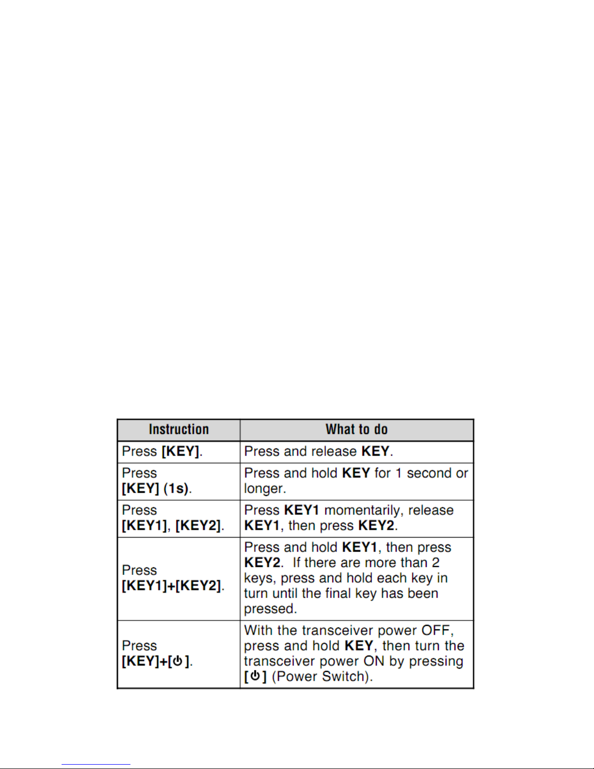
WRITING CONVENTIONS FOLLOWED IN THIS MANUAL
The writing conventions described below have been followed to simplify instructions and avoid
unnecessary repetition.
Page 8
PREPARATION
MOBILE INSTALLATION
When installing the transceiver, select a safe, convenient location inside your vehicle, which will
minimize dangers to your passengers and yourself while the vehicle is in motion. Consider
installing the unit at an appropriate position so that your knees or legs will not strike it during
sudden braking. Try to pick a well ventilated location which shielded from direct sunlight.
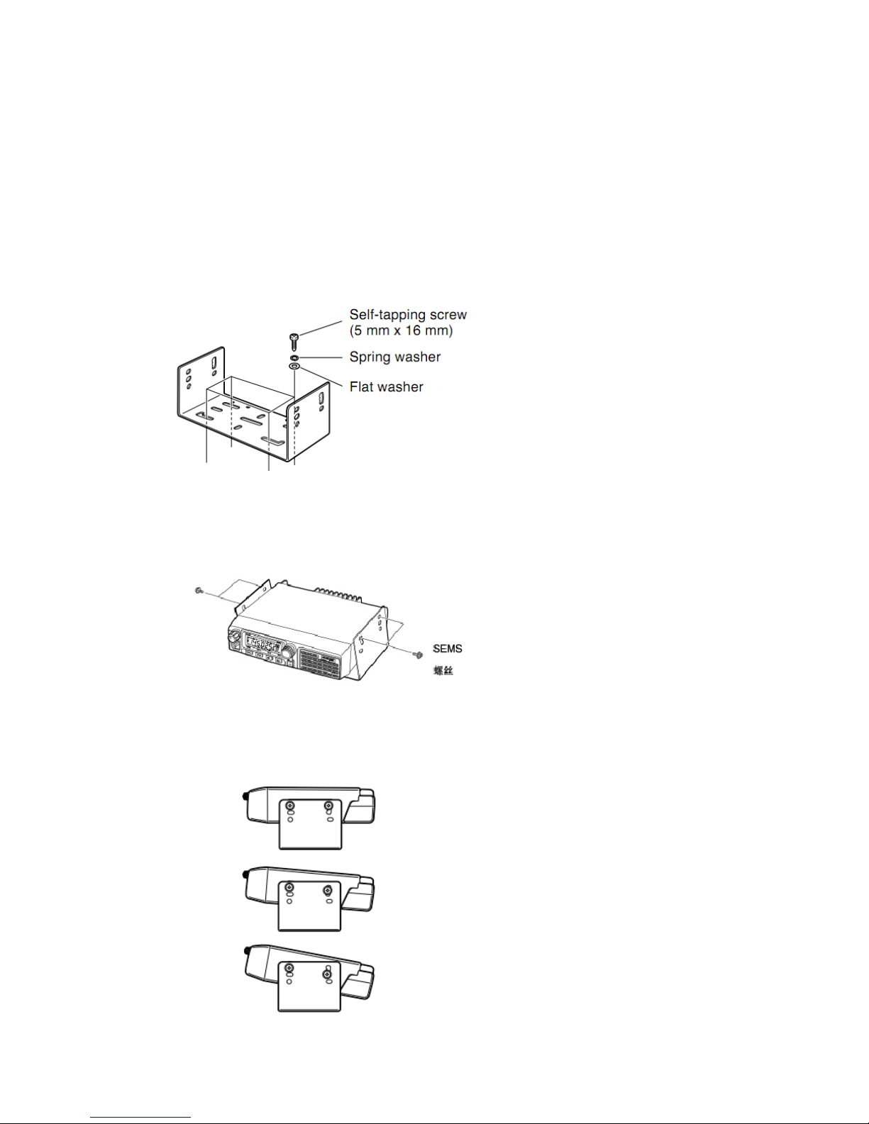
1 Install the mounting bracket in the vehicle, using the supplied self-tapping screws (4), flat
washers (4), and spring washers (4).
• The bracket must be installed so that the 3 screw hole positions on the side of the mounting
bracket are towards the rear of the bracket.
2 Place the transceiver, then insert and tighten the supplied hexagon SEMS screws (4) and flat
washers (4).
• Carefully check that all hardware is tightened to prevent the bracket or transceiver from
loosening for vehicle vibration.
[SEMS screws]
• Determine the appropriate angle of the transceiver, using the 3 screw hole positions on the side
of the mounting bracket.
Page 9
DC POWER CABLE CONNECTION
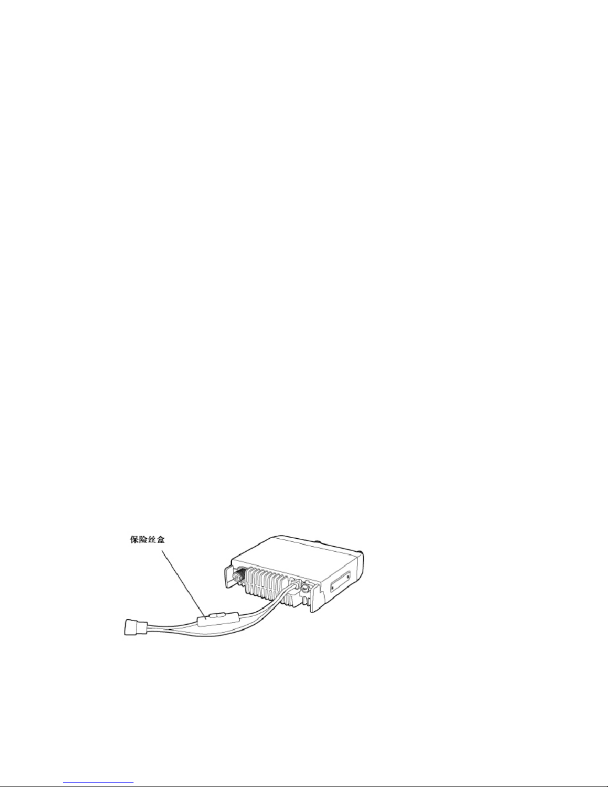
Caution: locate the power input connector as close to the transceiver as possible.
MOBILE OPERATION
The vehicle battery must have a nominal voltage of 12 V. Never connect the transceiver to a 24 V
battery. Be sure to use a 12 V vehicle battery that has sufficient current capacity. If the current to
the transceiver is insufficient, the display may darken during transmission, or transmit output
power may drop excessively.
1 Route the DC power cable supplied with the transceiver directly to the vehicle’s battery
terminals, adopting the shortest path from the transceiver.
• If using a noise filter, it should be installed with an insulator to prevent it from touching metal
on the vehicle.
•We recommend you not use the cigarette lighter socket as some cigarette lighter sockets
introduce an unacceptable voltage drop.
• The entire length of the cable must be dressed so it is isolated from heat, moisture, and the
engine secondary (high voltage) ignition system/ cables.
2 After the cable is in place, wrap heat-resistant tape around the fuse holder to protect it from
moisture and tie down the full run of cable.
3 To prevent the risk of short circuits, disconnect other wiring from the negative (–) battery
terminal before connecting the transceiver.
4 Confirm the correct polarity of the connections, then attach the power cable to the battery
terminals; red connects to the positive (+) terminal and black connects to the negative (–) terminal.
• Use the full length of the cable without cutting off excess even if the cable is longer than needed.
In particular, never remove the fuse holders from the cable.
5 Reconnect any wiring removed from the negative terminal.
6 Connect the DC power cable to the transceiver’s power supply connector.
• Press the connectors firmly together until the locking tab clicks.
【fuse holder】
Page 10

FIXED STATION OPERATION
In order to use this transceiver for fixed station operation, you need a separate 13.8V DC power
supply [not included]. The recommended current capacity of your power supply is 12A.
1 Connect the DC power cable to the regular DC power supply and ensure that the polarities are
correct (Red: positive, Black: negative).
• Do not directly connect the transceiver to an AC outlet.
• Use the supplied DC power cable to connect the transceiver to a regular power supply.
• Do not substitute a cable with smaller gauge wires.
2 Connect the transceiver’s DC power connector to the connector on the DC power cable.
• Press the connectors firmly together until the locking tab clicks.
[ fuse holder]
Notes:
For full capabilities performance of your transceiver, we recommend using the optional PS-33
(20.5A, 25% duty cycle) power supply.
Before connecting the DC power supply to the transceiver, be sure to switch the transceiver and
the DC power supply OFF.
Do not plug the DC power supply into an AC outlet until you make all connections.
Page 11
REPLACING FUSES
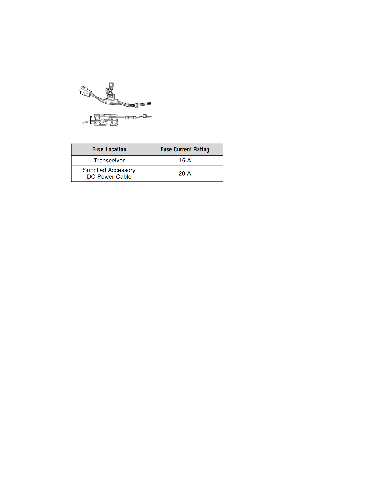
If the fuse blows, determine the cause, then correct the problem. After the problem is resolved,
replace the fuse. If newly installed fuses constantly blow, disconnect the power cable and contact
your authorized HYS+LOGO dealer or an authorized HYS+LOGO service center for assistance.
Caution: Only use fuses of the specified type and rating; otherwise the transceiver could be
damaged.
Notes: If the transceiver has been used for a long period when the vehicle battery is not fully
charged, or when the engine is OFF, the battery may become discharged, and will not have
sufficient reserves to start the vehicle. Avoid using the transceiver under these conditions.
ANTENNA CONNECTION
Before operating, install an efficient, well-tuned antenna. The success of your installation will
depend largely on the type of antenna and its correct installation. The transceiver can have
excellent performance if the antenna system and its installation are given careful attention.
Use a 50 Ω impedance antenna and low-loss coaxial feed line that has a characteristic impedance
of 50 Ω, to match with the transceiver input impedance. Coupling the antenna to the transceiver
via feed lines having an impedance other than 50 Ω will reduce the efficiency of the antenna
system and can cause interference to nearby broadcast television receivers, radio receivers, and
other electronic equipment.
Note: E market models use an N-type antenna connector while other models use an M-type
(SO-239) connector.
Caution: Transmitting without having connected an antenna or other matched load may damage
the transceiver. Always connect the antenna to the transceiver before transmitting.
All fixed stations should be equipped with a lightning arrester to reduce the risk of fire, electric
shock, and transceiver damage.
Page 12
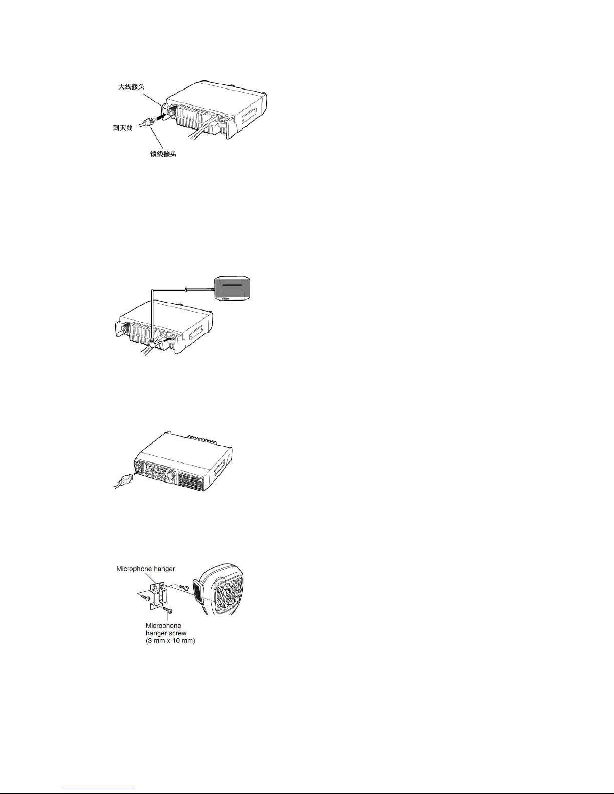
[antenna connector, to antenna, feed line connector]
ACCESSORY CONNECTIONS
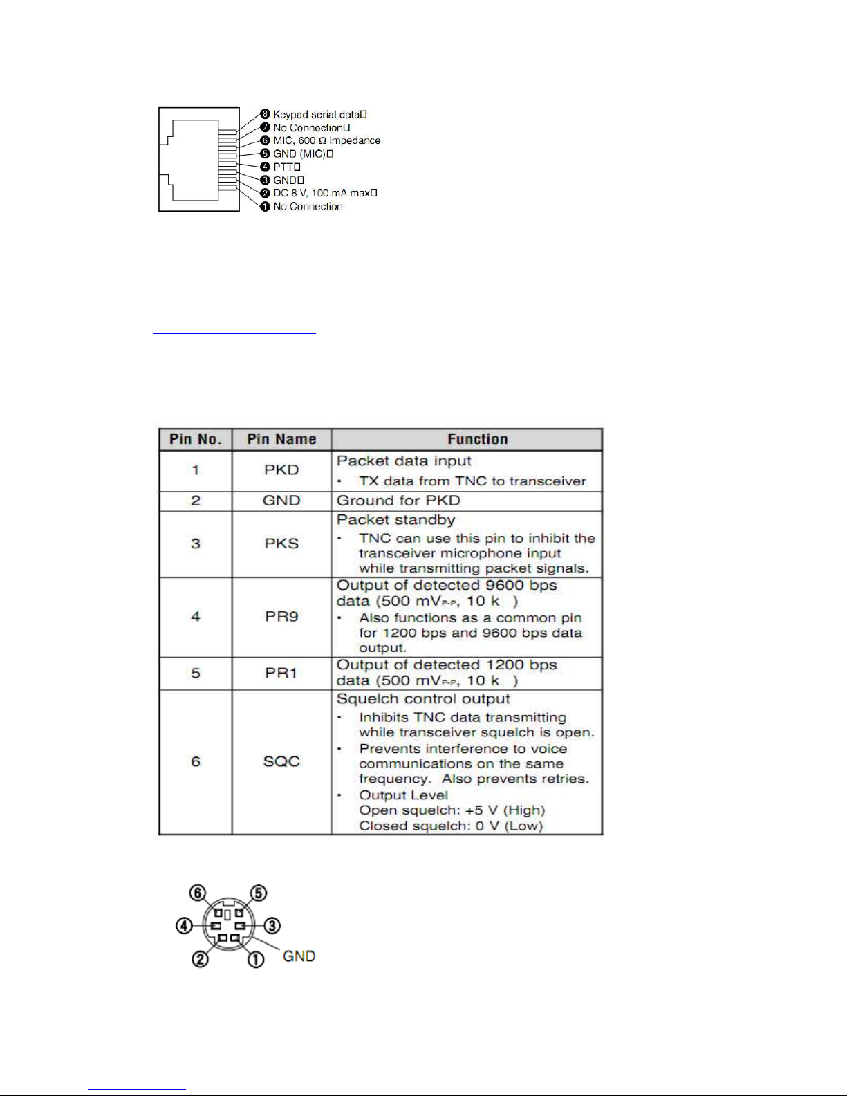
EXTERNAL SPEAKER
If you plan to use an external speaker, choose a speaker with an impedance of 8 Ω. The external
speaker jack accepts a 3.5 mm mono (2-conductor) plug. We recommend using the SP-50B
speaker.
MICROPHONE
For voice communications, connect a 600 Ω Microphone equipped with an 8-pin modular plug
into the modular socket on the front of the main unit. Press firmly on the plug until the locking tab
clicks.
Attach the supplied Microphone hanger in an appropriate location using the screws included in the
screw set.
Page 13
PC CONNECTION
To utilize the optional MCP-1A software, you must first connect the transceiver to your PC using
an optional programming cable (via the Microphone jack).
The MCP-1A is free downloadable software available from HYS+LOGO at the following URL:
http://www.trustcomnctn.com or ask our sales to send it by e-mail.
Note: Ask your dealer about purchasing a programming cable.
CONNECTING TO A TNC [E market models only ]
To connect an external TNC to the transceiver, use an optional PG-5A cable. The DATA connector
on the rear of the transceiver matches with the 6-pin mini-DIN plug on this cable.
Page 14

Note:
If the external TNC has a common pin for 1200 bps and 9600 bps data output, connect this pin to
the DATA connector PR9 pin. Shorting the PR9 and PR1 pins will cause the TNC to malfunction.
Adjust the transceiver data communication speed (1200 bps or 9600 bps) as necessary {page 54}.
If DC voltage is input to the PR1 pin, the external TNC may not function. If this problem
happens, add a 10 µF capacitor between the PR1 pin and the TNC. Be careful with the polarity of
the capacitor.
YOUR FIRST QSO
Are you ready to give your transceiver a quick try? Reading this section should get your voice on
the air right away. The instructions below are intended as a quick guide. If you encounter
problems or there is something you would like to know more, read the detailed explanations given
later in this manual.
1 Press [ ] (Power) briefly to switch the transceiver power ON.
A high pitched double beep sounds and a Power-on message appears momentarily. The various
indicators and the current operating frequency appear on the LCD.
The transceiver stores the current parameters when it is turned OFF and automatically recalls
those parameters next time you turn the transceiver ON.
2 Turn the Volume control clockwise, to the 9 o’clock position.
3 Turn the Tuning control to select a reception frequency.
You may continue turning the Volume control to adjust the volume level of the signal.
4 To transmit, hold the Microphone approximately 5cm (2 inches) from your mouth.
Page 15
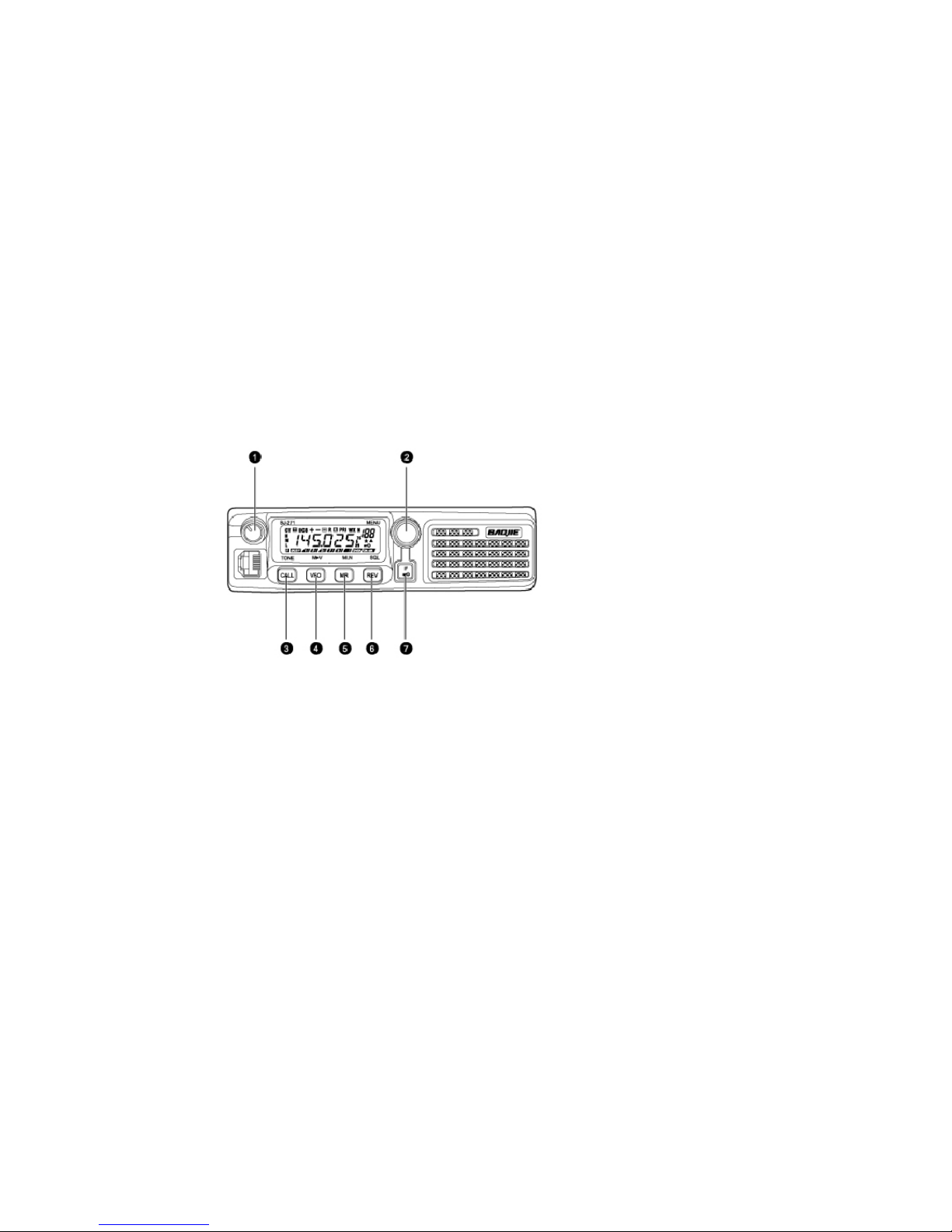
5 Press and hold MIC [PTT], then speak in your normal tone of voice.
6 Release MIC [PTT] to receive.
7 Repeat steps 4, 5, and 6 to continue communication.
GETTING ACQUAINTED
FRONT PANEL
Note: This section describes only the main functions of the front panel controls. Explanations for
functions not described here will be provided in the appropriate sections of this instruction
manual.
1 (Power) switch/ Volume control
Press to switch the transceiver power ON or OFF {page 14}.
Turn it to adjust the level of the receive audio from the speaker {page 14}.
2 MENU button/ Tuning control
Press to enter MHz Mode {page 16}. In this mode, you can change the operating frequency in 1
MHz steps using the Tuning control or MIC [UP]/[DWN]. Press and hold for 1 second while in
VFO Mode to begin MHz Scan {page 41} or while in MR Mode to begin Group Scan {page 42}.
Press [F] then press [MENU] to enter Menu Mode {page 18}. Turn to select:
• Operating frequencies when in VFO Mode {page 15}.
• Memory Channels when in Memory Recall Mode {page 30}.
• Menu No.s when in Menu Mode {page 18}.
• Scan direction while scanning {pages 27, 37, 44, 46}.
3 CALL key
Press to recall the Call Channel {page 34}. Press and hold for 1 second while in VFO Mode to
begin Call/VFO Scan {page 40}. Press and hold for 1 second while in Memory Recall Mode to
begin Call/memory Scan {page 40}.
Press [F] then press [CALL] to activate the Tone {page 24}, CTCSS {page 43}, or DCS {page 45}
function.
4 VFO key
Page 16
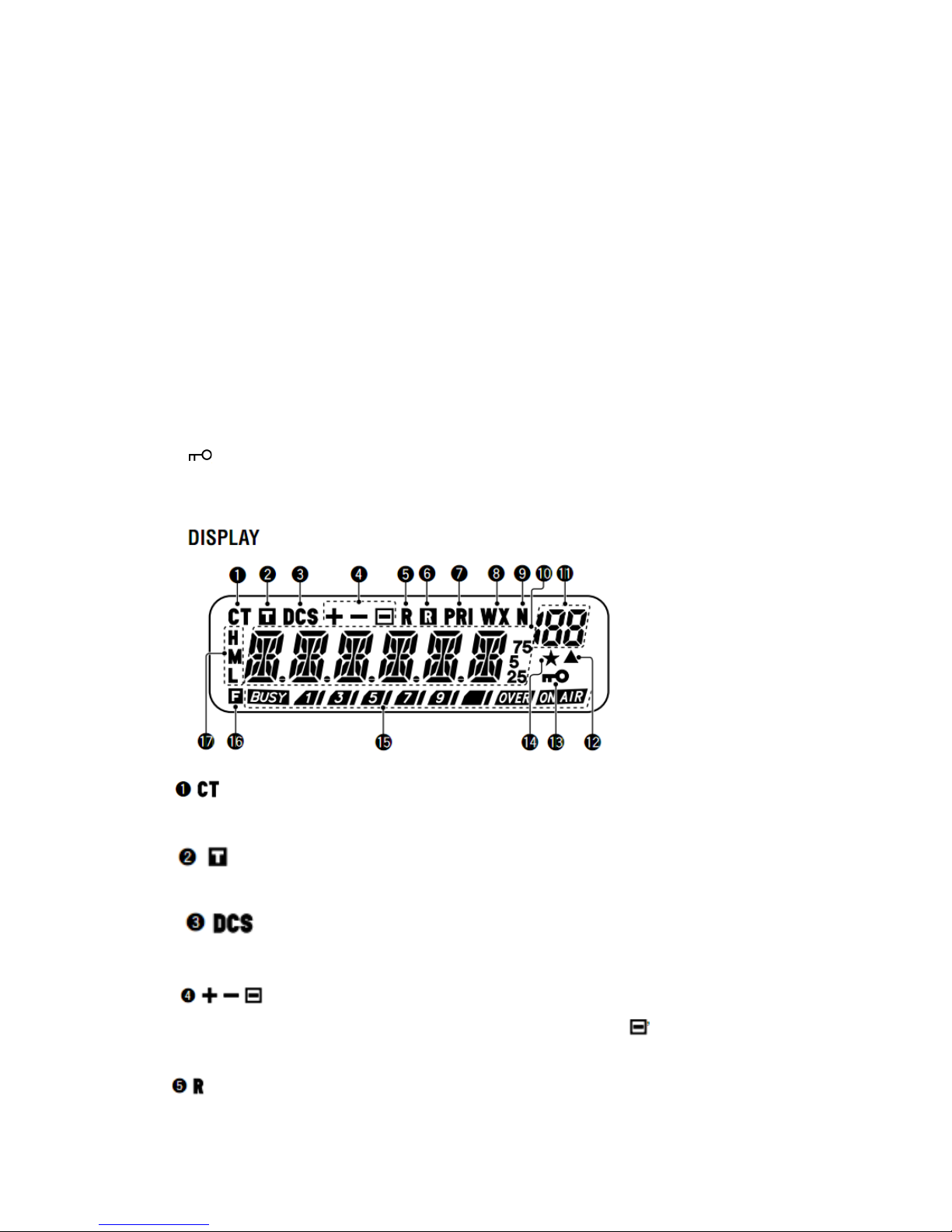
Press to enter VFO Mode {page 15}. In this mode, you can change the operating frequency using
the Tuning control or MIC [UP]/[DOWN]. Press and hold for 1 second while in VFO Mode to
begin Band Scan {page 37}. Press and hold for 1 second while in VFO Mode after programming a
scan range to begin Program Scan {page 38}. In MR Mode, press [F] then press [VFO] to transfer
the contents of the selected Memory Channel to the VFO {page 32}.
5 MR key
Press to enter Memory Recall Mode {page 30}. In this mode, you can change memory channels
using the Tuning control or MIC [UP]/[DWN]. Press and hold for 1 second while in Memory
Recall Mode to begin Memory Scan {page 39}. Press [F], and use the Tuning control to select the
desired channel, then press [MR] to reprogram the Call Channel or a Memory Channel {page 29}.
6 REV key
Press to switch the transmit frequency and receive frequency when operating with an offset {page
23} or an odd-split Memory Channel {page 28}.
Press [F] then press [REV] and rotate the Tuning control to increase or decrease the squelch level
{page 14}.
7 /F key
Press and hold for 1 second to lock the transceiver keys {page 54}.
Press momentarily to access the second functions of the transceiver keys.
Appears when the CTCSS function is activated {page 43}.
Appears when the Tone function is activated {page 24}.
Appears when the DCS function is activated {page 46}.
Appears when the repeater shift function is activated {pages 23, 30}. (“ ” is not used on this
transceiver.)
Page 17
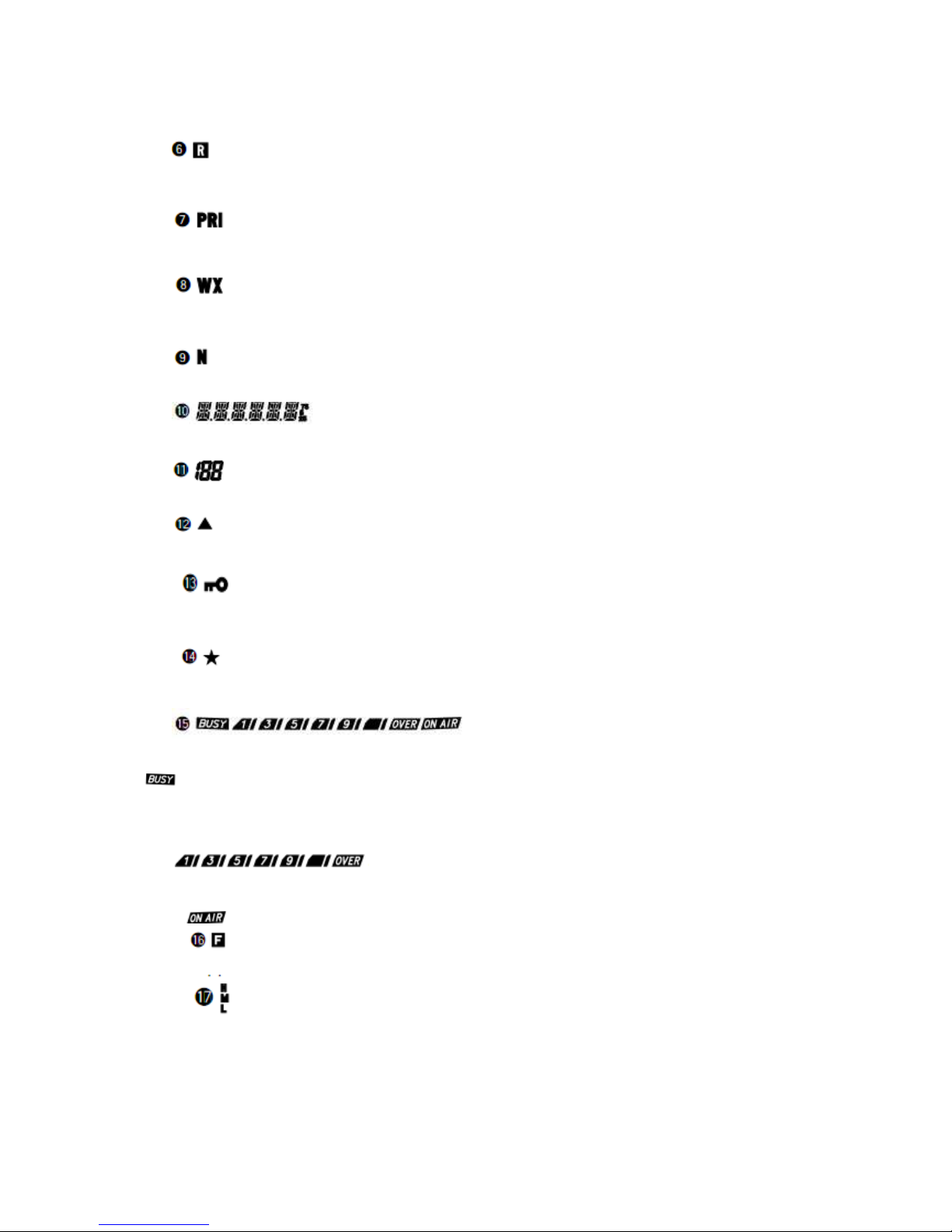
Appears when the Reverse function is activated {page 26}.
Appears when the Automatic Simplex Check (ASC) function is activated {page 26}.
Appears when the Priority Scan function is activated {page 41}.
Appears when the Weather Alert function is activated {page 35}. (K market models only.)
Appears when narrow FM Mode is selected {page 56}.
Displays the frequencies, Menu settings, Memory name and other information.
Displays the Menu No., Memory Channel number, and status {pages 18, 29}.
Appears when the displayed Memory Channel has data {page 29}.
Appears when the Key Lock function is ON {page 54}.
Appears when the Memory Channel Lockout function is ON {page 42}.
Shows the strength of transmitted {page 15} and received {page 51} signals.
indicates the squelch is open and the frequency is“busy”. It also appears when the squelch
level is set to minimum {page 14}. If using CTCSS or DCS, it indicates the squelch is open due to
a received signal that contains the same CTCSS tone or DCS code set in your transceiver.
acts as an S-meter while receiving and an RF power meter while
transmitting.
indicates the transceiver is transmitting.
Appears when the function key is pressed.
H appears when high power transmission is selected and L appears when low power is selected
{page 15}. (“M” is not used on this transceiver.)
Page 18
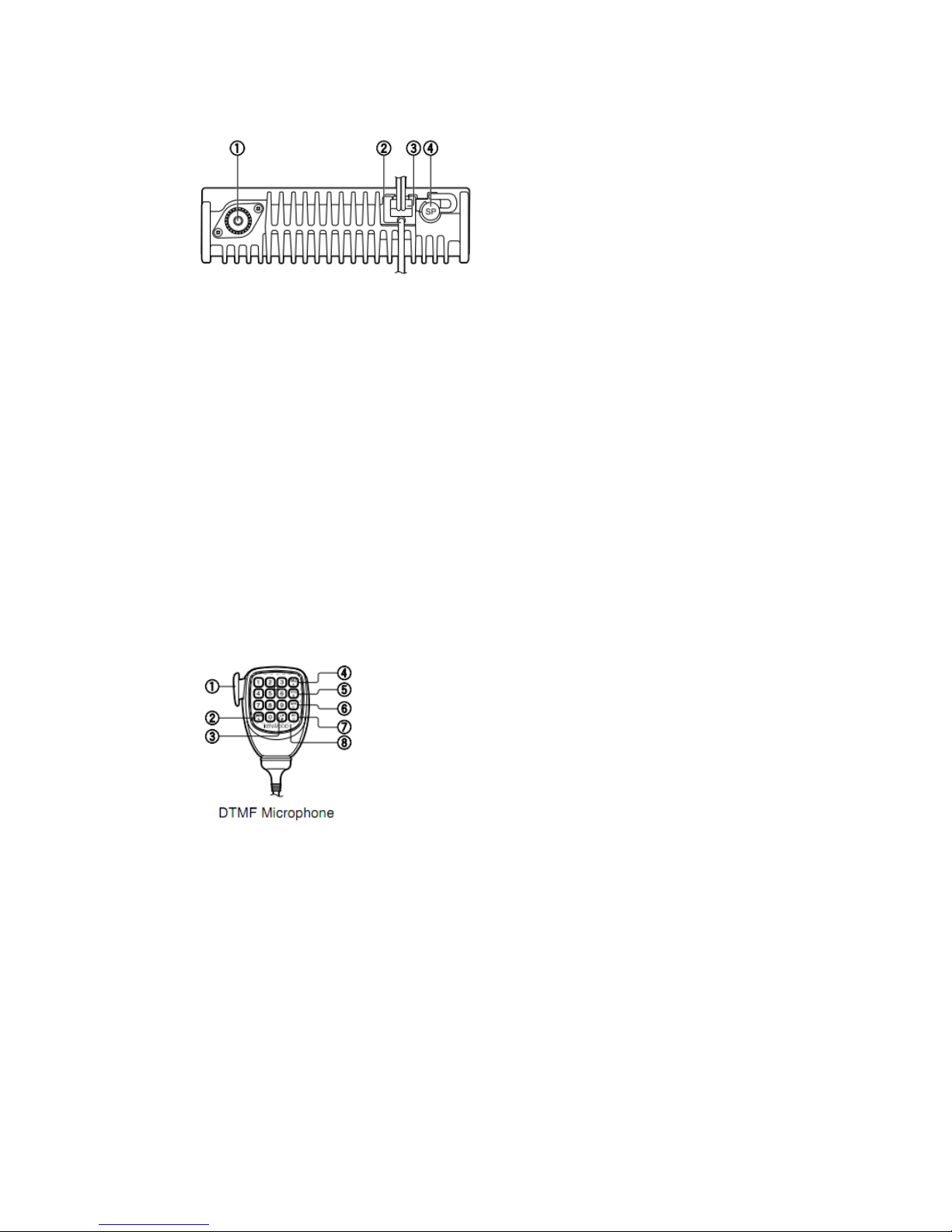
REAR PANEL
1 Antenna connector
Connect an external antenna {page 5} here. When making test transmissions, connect a dummy
load to replace the antenna. The antenna system or load should have an impedance of 50 Ω.
Note: E market models use an N-type antenna connector while other models use an M-type
(SO-239) connector.
2 Data cable (E market modelss only)
Connect this cable to a TNC {page 7}.
3 13.8 V DC Power cable
Connect a 13.8 V DC power source here. Use the supplied DC power cable {pages 3, 4}.
4 SP (speaker) jack
If desired, connect an optional external speaker for clearer audio. This jack accepts a 3.5mm
mono (2-conductor) plug. See page 6.
MICROPHONE
1 PTT (Push-to-Talk) switch
Press and hold to transmit. Release to receive.
2 DOWN/*key
Press to lower the operating frequency, Memory Channel number, Menu Number, etc. Hold on
to repeat the action. Also press to switch between values for functions with multiple choices.
Press and hold MIC [PTT], then press [DOWN/*] to transmit .
3 UP/# key
Press to raise the operating frequency, Memory Channel number, Menu Number, etc. Hold on to
repeat the action. Also press to switch between values for functions with multiple choices.
Press and hold MIC [PTT], then press [UP/ #] to transmit.
Page 19
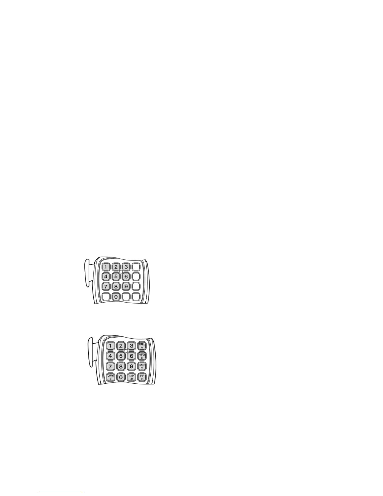
4 CALL/A key
Identical to the front panel CALL key. This key can be reprogrammed if desired {page 55}.
Press and hold MIC [PTT], then press [CALL/A] to transmit A..
5 VFO/B key
Identical to the front panel VFO key. This key can be reprogrammed if desired {page 55}.
Press and hold MIC [PTT], then press [VFO/B] to transmit B.
6 MR/C key
Identical to the front panel MR key. This key can be reprogrammed if desired {page 55}. Press
and hold MIC [PTT], then press [MR/C] to transmit C.
7 PF/D key
The default function of this key is 1 MHz step. This key can be reprogrammed if desired {page
55}.Press and hold MIC [PTT], then press [PF/D] to transmit D.
8 DTMF key
This 16-key keypad is used for DTMF functions {page 47} or to directly enter an operating
frequency {page 16}, or a Memory Channel number {page 30}. The keypad can also be used to
program a Memory Channel name, Power-on message, or other character strings {page 58}.
MIC KEYPAD DIRECT ENTRY
The Microphone keypad (keypad models only) allows you to make various entries depending on
which mode the transceiver is in.
In VFO or Memory Recall mode, use the MIC keypad to select a frequency {page 16} or
Memory Channel number {page 30}. At first press the MIC PF key assigned with the ENTER
function {page 55}.
To manually send a DTMF number, press and hold MIC [PTT], then press the DTMF keys on
the MIC keypad {page 47} in sequence.
You can also use the MIC keypad to program a Memory Channel name, Power-on message, or
other character strings {page 58}.
Page 20
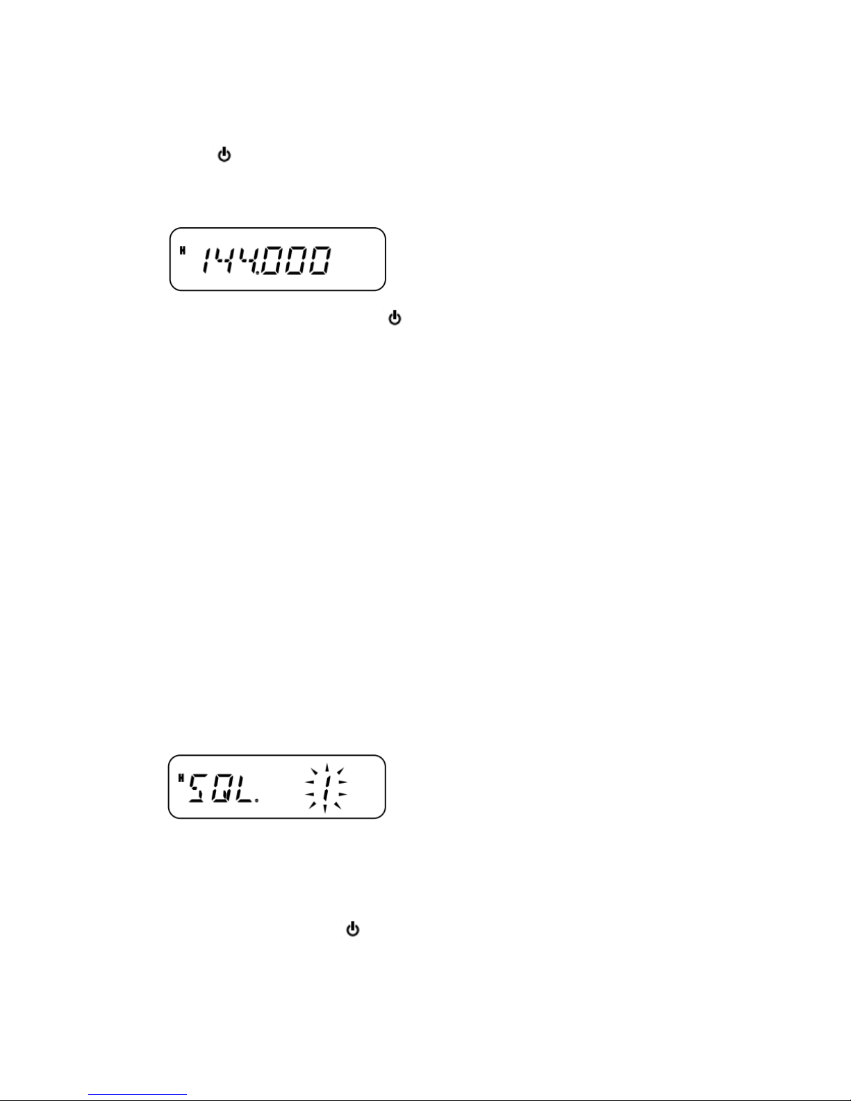
BASIC OPERATIONS
SWITCHING THE POWER ON/OFF
1 Press [ ] (Power) to switch the transceiver power ON.
•A high pitched double beep sounds and a Power-on message {page 56} appears briefly,
followed by the frequency and other indicators.
2 To switch the transceiver OFF, press [ ] (Power) (1s).
• When you turn the transceiver OFF, a low pitched double beep sounds.
• The transceiver stores the current frequency and parameters when it is turned OFF and recalls
these parameters the next time you turn the transceiver ON.
ADJUSTING THE VOLUME
Turn the Volume control clockwise to increase the audio output level and counterclockwise to
decrease the output level.
If you are not receiving a signal, press the MIC PF key assigned with the MONI function {page
52}, then adjust the Volume control to a comfortable audio output level. Press the MONI key
again to cancel the Monitor function.
ADJUSTING THE SQUELCH
The purpose of Squelch is to mute the speaker when no signals are present. With the squelch
level correctly set, you will hear sound only while actually receiving signals. The higher the
selected squelch level, the stronger the signals must be to receive. The appropriate squelch level
depends on the ambient RF noise conditions.
1 Press [F], [REV].
• The current squelch level appears.
2 Turn the Tuning control to adjust the level.
• Select the level at which the background noise is just eliminated when no signal is present.
• The higher the level, the stronger the signals must be to receive.
• 10 different levels can be set. (0: Minimum ~ 9: Maximum; 1 is the default value)
3 Press any key other than [ ] (Power) to store the new setting and exit the squelch
adjustment mode.
Page 21
TRANSMITTING
1 To transmit, hold the Microphone approximately 5cm (2 inches) from your mouth, then press
and hold MIC [PTT] and speak into the Microphone in your normal tone of voice.
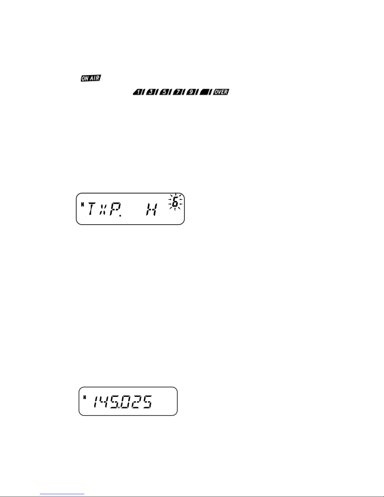
•“ ” and the RF Power meter appears on display. The RF Power meter shows the relative
transmit output power ( ).
• If you press MIC [PTT] while you are outside the transmission coverage, a high pitched error
beep will sound.
2 When you finish speaking, release MIC [PTT].
Note: If you continuously transmit for longer than the time specified in Menu No. 21 (default is
10 minutes) {page 57}, the internal time-out timer generates a warning beep and the transceiver
stops transmitting. In this case, release MIC [PTT] and let the transceiver stop working for a
while, then press MIC [PTT] again to resume transmission.
SELECTING AN OUTPUT POWER
You can configure different Tx power levels.
1 Press [F], [MENU] and turn the Tuning control to select Menu No. 6 (TXP).
2 Press [MENU] and turn the Tuning control to select“H” (high; default) or “L” (low) power.
3 Press [MENU] to store the setting or any other key to cancel.
4 Press any key other than [MENU] to exit Menu Mode.
CASUTION:
Do not transmit at high output power for an extended period of time. The transceiver could
overheat and malfunction.
Continuous transmission causes the heat sink to overheat. Never touch the heat sink when it
may be hot.
Note: When the transceiver overheats because of ambient high temperature or continuous
transmission, the protective circuit may function to lower transmit output power.
SELECTING A FREQUENCY
VFO MODE
This is the basic mode for changing the operating frequency. To enter VFO Mode, press [VFO].
Turn the Tuning control clockwise to increase the frequency and counterclockwise to decrease
the frequency, or use MIC [UP]/[DWN].
• Press and hold MIC [UP]/[DWN] to step the frequency continuously.
MHZ MODE
If the desired operating frequency is far away from the current frequency, it is quicker to use the
Page 22
MHz Tuning Mode.
To adjust the MHz digit:
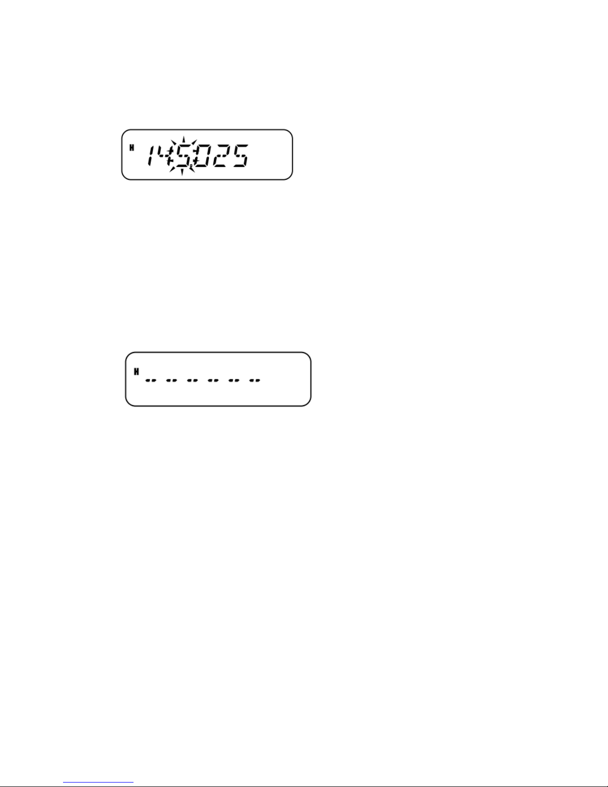
1 While in VFO or Call Mode, press [MENU].
• The MHz digit blinks.
2 Turn the Tuning control to select the desired MHz value.
3 Press any key to set the selected frequency and return to normal VFO Mode.
4 Continue adjusting the frequency as necessary, using the Tuning control or MIC
[UP]/[DOWN].
DIRECT FREQUENCY ENTRY
In addition to turning the Tuning control or pressing MIC[UP]/[DWN], there is another way to
select the frequency. When the desired frequency is far away from the current frequency, you
can directly enter a frequency using the MIC keypad (keypad models only).
1 Press [VFO].
•You must be in VFO mode to make a direct frequency entry.
2 Press the MIC PF key assigned the ENTER function {page 55}.
3 Press the numeric keys ([0] to [9]) to enter your desired frequency.
• Pressing MIC Enter fills all remaining digits (the digits you did not enter) with 0 and
completes the entry. For example, to select 145.000 MHz, press [1], [4], [5] and press MIC
Enter to complete the entry.
• If you want to revise the MHz digits only, leaving the kHz digits as they are, press MIC [VFO]
in place of MIC Enter.
Example 1
To enter 145.750 MHz:
Key in Display
[Enter] – – – – – –
[1], [4], [5] 1 4 5. – – –
[7], [5], [0] 1 4 5. 7 5 0
Example 2
To enter 145.000 MHz:
Key in Display
[Enter] – – – – – –
[1], [4], [5] 1 4 5. – – –
[Enter] 1 4 5. 0 0 0
Example 3
To change 144.650 MHz to 145.650 MHz:
Page 23
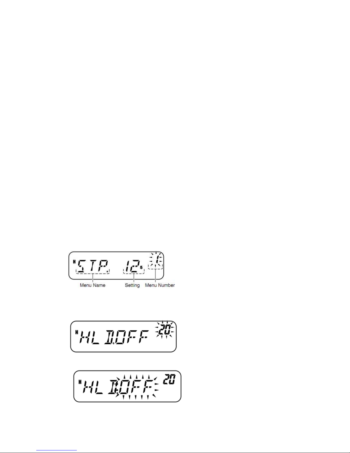
Key in Display
1 4 4. 6 5 0
[Enter] – – – – – –
[1], [4], [5] 1 4 5. – – –
MIC [VFO] 1 4 5. 6 5 0
Note: If the entered frequency does not match with the current frequency step size, the
frequency is automatically rounded down to the next available frequency. When the desired
frequency cannot be entered exactly, confirm the frequency step size {page 53}.
MENU SETUP
WHAT IS A MENU?
Many functions on this transceiver are selected or configured via a software-controlled Menu
rather than through the physical controls of the transceiver. Once you become familiar with the
Menu system, you will appreciate its versatility. You can customize the various timings, settings,
and programming functions on this transceiver to meet your needs without using many controls
and switches.
MENU ACCESS
1 Press [F], [MENU].
•A brief explanation of the menu, and the setting and Menu No. will be demonstrated on
display.
2 Turn the Tuning control to select your desired Menu.
• As you change the Menu No., a brief explanation of each menu appears along with its current
parameter.
3 Press [MENU] to configure the parameter of the currently selected Menu No.
Page 24
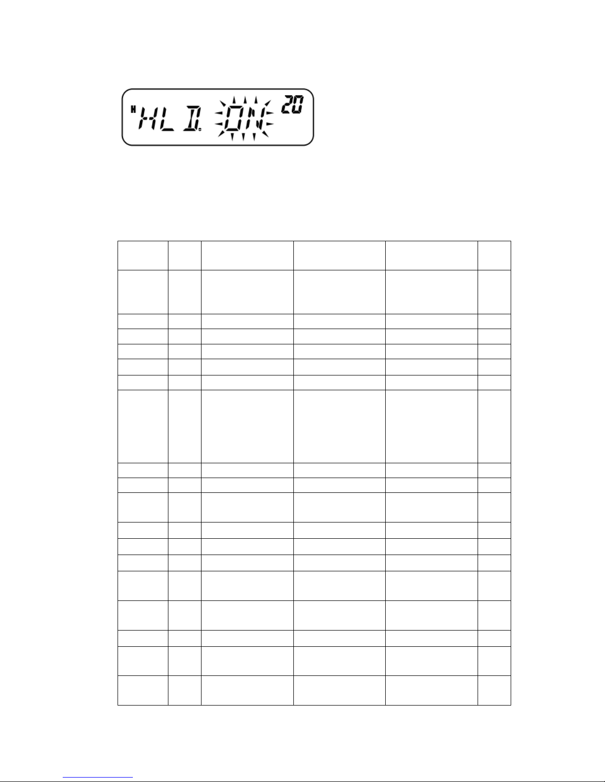
4 Turn the Tuning control to select your desired parameter.
5 Press [MENU] to store the new setting or any other key to cancel.
6 Press any key other than [MENU] to exit Menu Mode.
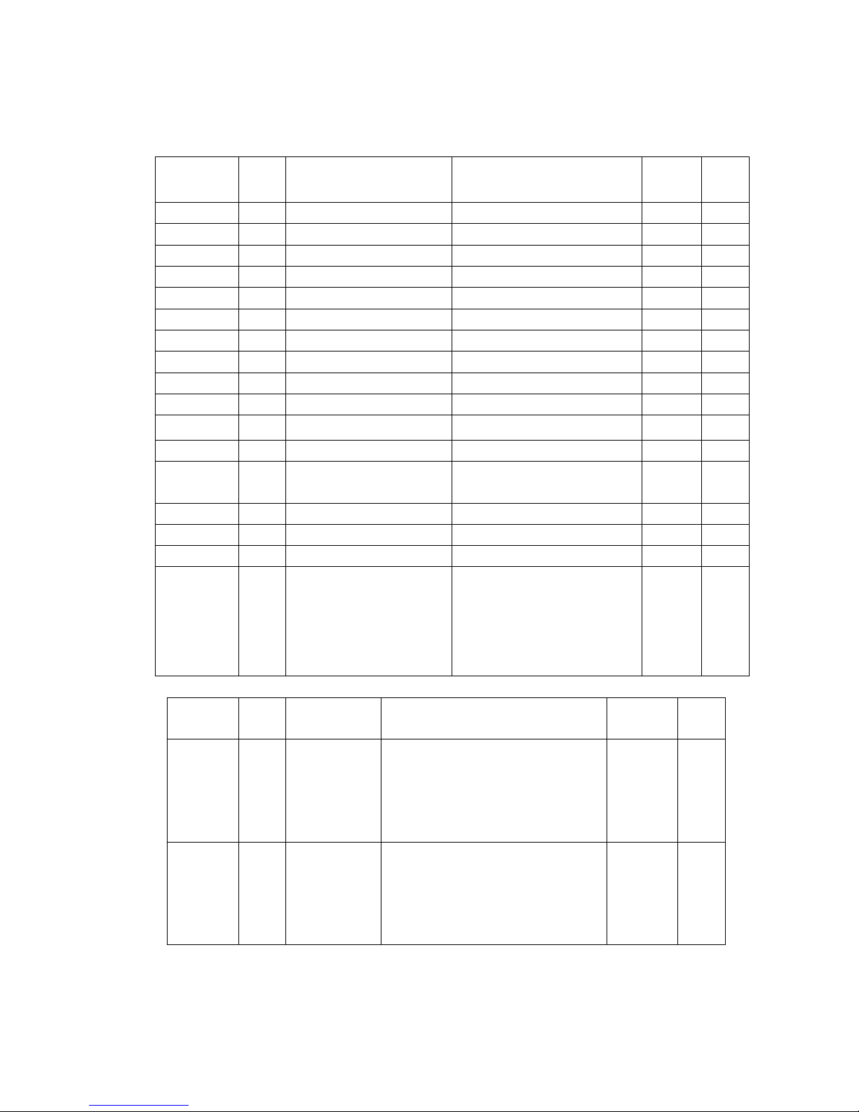
MENU FUNCTION LIST
On
Display
Menu
No.
Function
Selections
Default
Ref.
Page
STP 1 Frequency step size 2.5(VHF)/5./6.25/10
/12.5/15/20/25/30/5
0/100KHz
VHF: 12.5kHz
UHF: 25kHz
53
T 2 Tone frequency 67.0~254.1Hz 88.5 24
CT 3 CTCSS frequency 67.0~254.1Hz 88.5 44
DCS 4 DCS code 023~754 023 45
SFT 5 Shift direction OFF/+/- OFF 23
TXP 6 Tx power High/Low High 15
P.VFO 7 Programmable VFO VHF:136~173MHZ
UHF(C):
400~429MHZ
UHF(C2):
440~479mMHZ
VHF: 136~173MHZ
UHF(C):
400~429MHZ
UHF(C2):
440~479mMHZ
57
SSQ 8 S-Meter squelch ON/OFF OFF 51
SQH 9 Squelch hang time OFF/125/250/500ms OFF 52
OFFSET 10 Repeater offset
frequency
0~69.95MHZ VHF: 600kHz
UHF: 5MHz
23
ARO 11 Auto repeater offset ON/OFF OFF 25
PRI 12 Priority scan ON/OFF OFF 41
SCAN 13 Scan resume method TO/CO/SE TO 42
L.OUT 14 Memory channel
lockout
ON/OFF OFF 42
M.CH 15 Memory channel
capacity
100/200 100 28
M.NAME 16 Memory name 6 characters - 31
MDF 17 Memory name/
frequency display
MN/FRQ MN 31
APO 18 Auto power-off OFF/30/60/90/120/1
80 min
Off 51
Page 25
On
Display
Menu
No.
Function
Selections
Default
Ref.
Page
CK 19 CALL key CALL/1750 CALL 25,34
HLD 20 1750Hz tone Tx hold ON/OFF OFF 25
TOT 21 Time out timer 3/5/10 min 10 57
BCL 22 Busy channel lockout ON/OFF OFF 53
P.ON.MSG 23 Power-on message 6 characters - 56
BP 24 Beep ON/OFF ON 52
BS 25 Beat shift ON/OFF OFF 51
FMN 26 Narrow FM ON/OFF OFF 56
ENC 27 Tuning control lock ON/OFF OFF 55
DTMF.MR 28 Auto dialer Up to 16 digits - 48
SPD 29 DTMF Tx speed FA/SL FA 49
DT.H 30 DTMF Tx hold ON/OFF OFF 48
PA 31 DTMF pause period 100/250/500/750/1000/1500/
2000 ms
500 50
DT.L 32 DTMF key lock ON/OFF OFF 50
DT.M 33 DTMF monitor ON/OFF OFF 47
MC.L 34 Microphone key lock ON/OFF OFF 59
PF1 35 Microphone programmable
function key
MONI/ENTER/1750/VFO/MR
/CALL/MHZ/REV/SQL/M—
V/M.IN/C.IN/MENU/SHIFT/L
OW/BRIGHT/LOCK/TONE/
STEP
MHZ 55
On
Display
Menu
No.
Function
Selections Default Ref.
Page
PF2 36 Microphone
programmable
function key
MONI/ENTER/1750/VFO/MR/
CALL/MHZ/REV/SQL/M—V/
M.IN/C.IN/MENU/SHIFT/LOW/
BRIGHT/LOCK/TONE/STEP
MR 55
PF3 37 Microphone
programmable
function key
MONI/ENTER/1750/VFO/MR/
CALL/MHZ/REV/SQL/M—V/
M.IN/C.IN/MENU/SHIFT/LOW/
BRIGHT/LOCK/TONE/STEP
VFO 55
Page 26
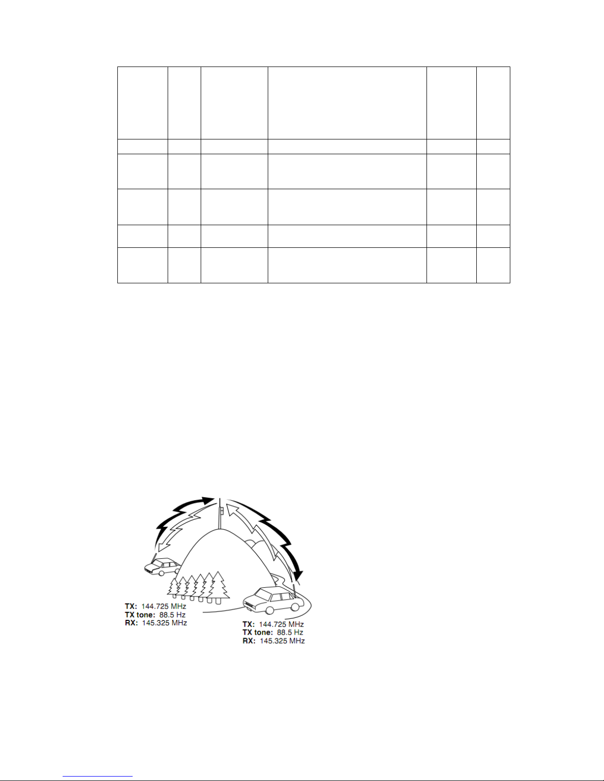
PF4 38 Microphone
programmable
function key
MONI/ENTER/1750/VFO/MR/
CALL/MHZ/REV/SQL/M—V/
M.IN/C.IN/MENU/SHIFT/LOW/
BRIGHT/LOCK/TONE/STEP
CALL 55
DT 39 Data Tx speed 1200/9600bps 1200 54
BRIGHT 40 Display
brightness
ON/OFF Max.
level
53
ABR 41 Auto display
brightness
ON/OFF OFF 53
WXA1 42 Weather alert VFO/FULL OFF 35
RESET 99 Reset
selection
VFO 62
WXA (Weather Alert) is available only for K market models.
OPERATING THROUGH REPEATER
Repeaters, which are often installed and maintained by radio clubs, are usually located on
mountain tops or other elevated locations. They generally operate at higher ERP (Effective
Radiated Power) than a typical station. This combination of elevation and high ERP allows
communications over much greater distances than communicating without using repeaters.
Most repeaters use a receive and transmit frequency pair with a standard or non-standard offset
(odd-split). In addition, some repeaters must receive a tone from the transceiver to permit access.
For details, consult your local repeater reference.
Page 27
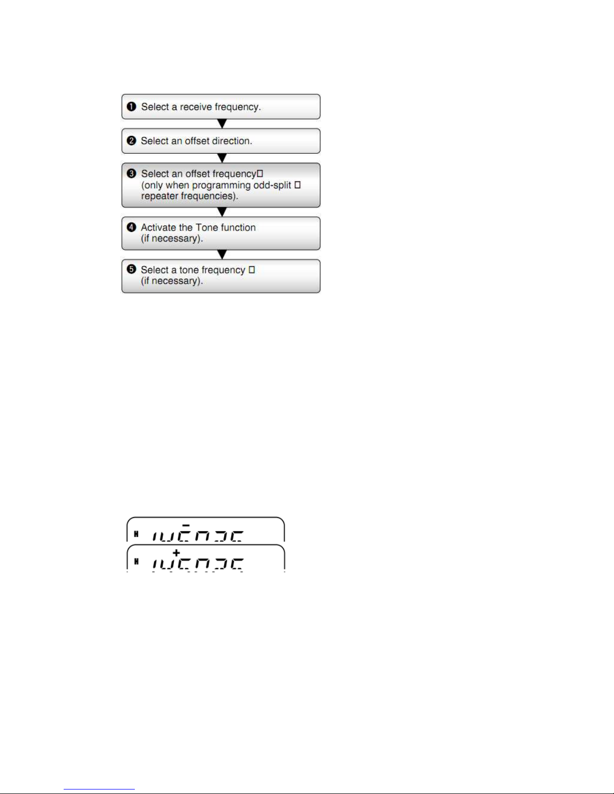
OFFSET PROGRAMMING FLOW
If you store all the above data in a Memory Channel, you will not need to reprogram the
parameters every time. Refer to “MEMORY CHANNELS” {page 28}.
PROGRAMMING AN OFFSET
You must first select an amateur radio repeater downlink frequency as described in “SELECTING
AN OFFSET FREQUENCY”.
SELECTING AN OFFSET DIRECTION
Select whether the transmit frequency will be higher (+) or lower (–) than the receive frequency.
1 Press [F], [MENU] and turn the Tuning control to select Menu No. 5 (SFT).
2 Press [MENU] and turn the Tuning control to select“+” or “–”.
3 Press [MENU] to store the setting or any other key to cancel.
4 Press any key other than [MENU] to exit Menu Mode.
“+” or “–” appears above the frequency, indicating which offset direction is selected.
If the offset transmit frequency falls outside the allowable range, transmission will be inhibited.
In this case, adjust the reception frequency so that the transmit frequency is within the band limits
or change the offset direction.
Note: While using an odd-split memory channel or transmitting, you cannot change the offset
direction.
SELECTING AN OFFSET FREQUENC
To access a repeater which requires an odd-split frequency pair, change the offset frequency from
the default which is used by most repeaters. The default offset frequency is 600 kHz on VHF,
5.0MHZ on UHF.
Page 28
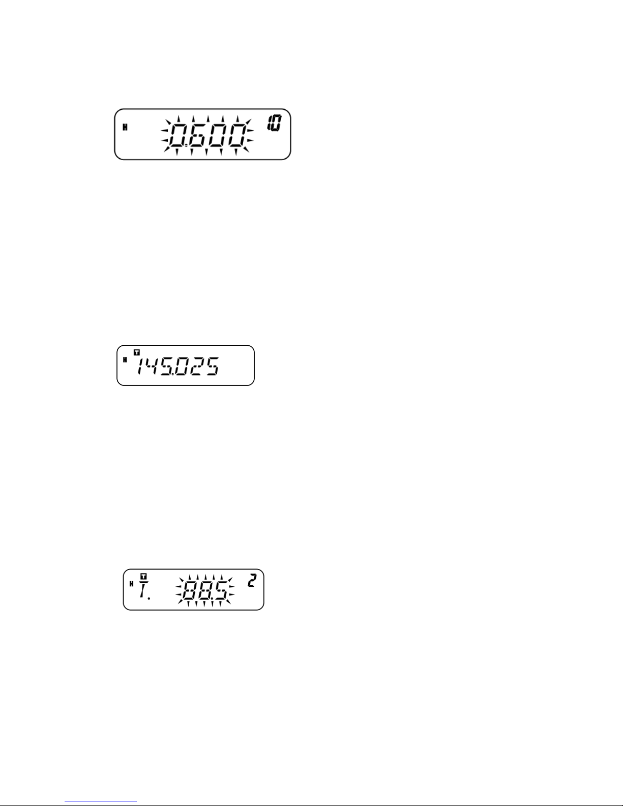
1 Press [F], [MENU] and turn the Tuning control to select Menu No. 10 (OFFSET).
2 Press [MENU] and turn the Tuning control to select the appropriate offset frequency.
The selectable range is from 0.00 MHz to 69.95 MHz in steps of 50 kHz.
3 Press [MENU] to store the setting or any other key to cancel.
4 Press any key other than [MENU] to exit Menu Mode.
Note: After changing the offset frequency, the new offset frequency will also be used by Auto
Repeater Offset.
ACTIVIATING THE TONE FUNCYION
To activate Tone, press [F], [CALL].
• As you press [F], [CALL], the selection cycles as follows:“OFF” ➞ “TONE” ➞ “CTCSS”
➞ “DCS” ➞ “OFF”.
• “T” appears on the upper part of display, indicating that the Tone function is activated.
Note: You cannot use the Tone function and CTCSS/ DCS functions simultaneously. Switching the
Tone function ON after having activated the CTCSS/ DCS functions deactivates the CTCSS/ DCS
functions.
E market models only: When you access repeaters that require a 1750 Hz tone, you do not need to
activate the Tone function. Simply press [CALL] without pressing MIC [PTT] to transmit a 1750
Hz tone (default setting).
SELECTING A TONE FREQUENCY
1 Press [F], [MENU] and turn the Tuning control to select Menu No. 2 (T).
2 Press [MENU] and turn the Tuning control to select the desired tone frequency (default is 88.5
Hz).
3 Press [MENU] to store the setting or any other key to cancel.
4 Press any key other than [MENU] to exit Menu Mode.
AVAILABLE TONE FREQUENCIES
Page 29
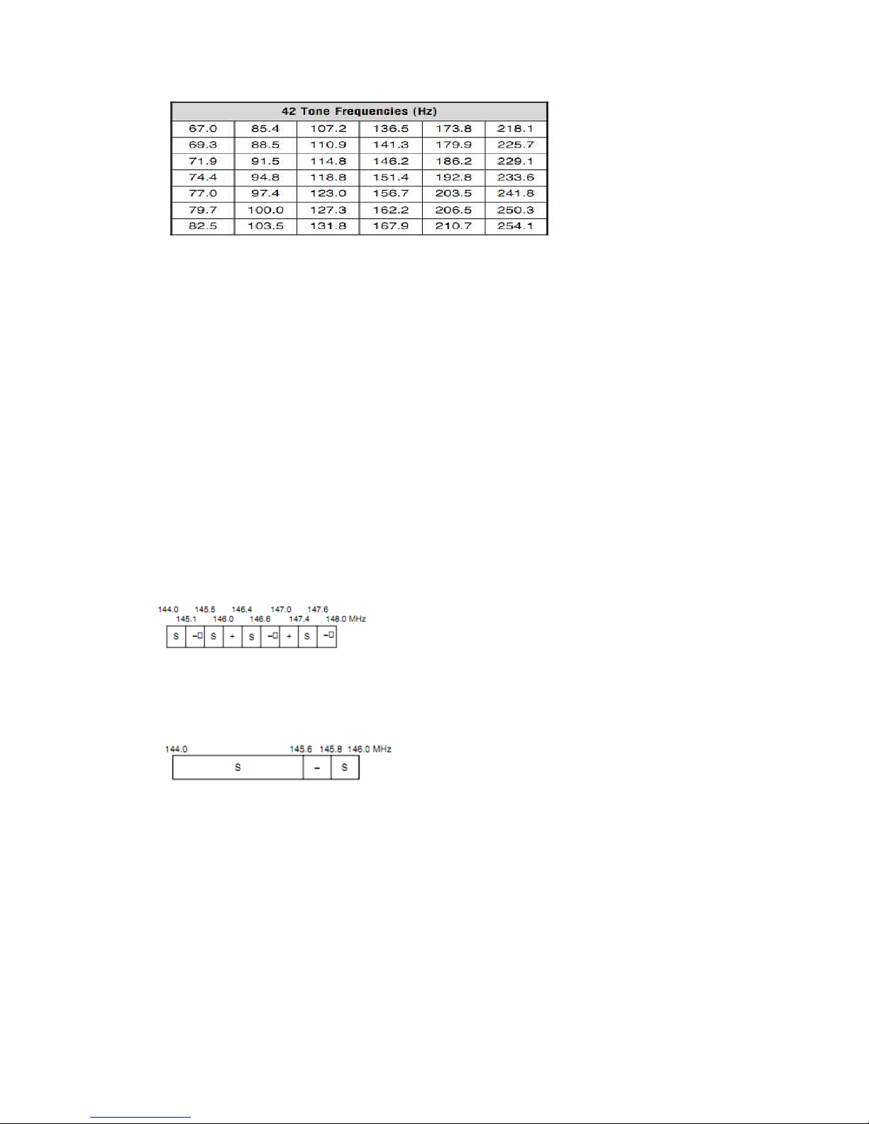
Note: 42 different tones are available for the transceiver including 37 EIA standard tones and 5
non-standard tones.
E market models only:
To transmit a 1750 Hz tone, simply press [CALL] without pressing MIC [PTT] (default setting).
Release [CALL] to quit transmitting. You can also make the transceiver remain in the transmit
mode for 2 seconds after releasing [CALL]; a 1750 Hz tone is not continuously transmitted.
Access Menu No. 20 (HLD) and select“ON”.
To use [CALL] for recalling the Call Channel in place of transmitting a 1750 Hz tone, access
Menu No. 19 (CK) and select“CALL”.
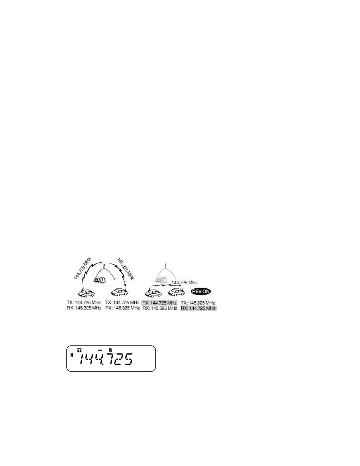
AUTOMATIC REPEATER OFFSET (K , E market models only)
This function automatically selects an offset direction, according to the frequency on the VHF
band. The transceiver is programmed for an offset direction as shown below. To obtain an
up-to-date band plan for repeater offset direction, contact your national Amateur Radio
association.
K market version only
S: Simplex
This complies with the standard ARRL band plan.
E market version only
S: Simplex
Note: Automatic Repeater Offset does not function when the Reverse function is ON. However,
pressing [REV] after Automatic Repeater Offset has selected an offset (split) status, exchanges the
receive and transmit frequencies.
1 Press [F], [MENU] and turn the Tuning control to select Menu No. 11 (ARO).
2 Press [MENU] and turn the Tuning control to switch the function “ON” (default) or “OFF”.
3 Press [MENU] to store the setting or any other key to cancel.
4 Press any key other than [MENU] to exit Menu Mode.
Page 30
TRANSMITTING A 1750 Hz TONE
Call Channel default settings:
• On E market models, pressing [CALL] causes the transceiver to transmit a 1750 Hz tone.
• On other market models, pressing [CALL] shifts the transceiver to the Call Channel {page 35}.
Most of the repeaters in Europe require the transceiver to transmit a 1750 Hz tone.
To change the setting of the CALL key:
1 Press [F], [MENU] and turn the Tuning control to select Menu No. 19 (CK).
2 Press [MENU] and turn the Tuning control to select“CALL” or “1750”.
3 Press [MENU] to store the setting or any other key to cancel.
4 Press any key other than [MENU] to exit Menu Mode.
Some repeaters in Europe must receive continuous signals for a certain period of time, following a
1750 Hz tone. This transceiver is also capable of remaining in the transmit mode for 2 seconds
after transmitting the tone.
1 Press [F], [MENU] and turn the Tuning control to select Menu No. 20 (HLD).
2 Press [MENU] and turn the Tuning control to select“ON” or “OFF” (default).
3 Press [MENU] to store the setting or any other key to cancel.
4 Press any key other than [MENU] to exit Menu Mode.
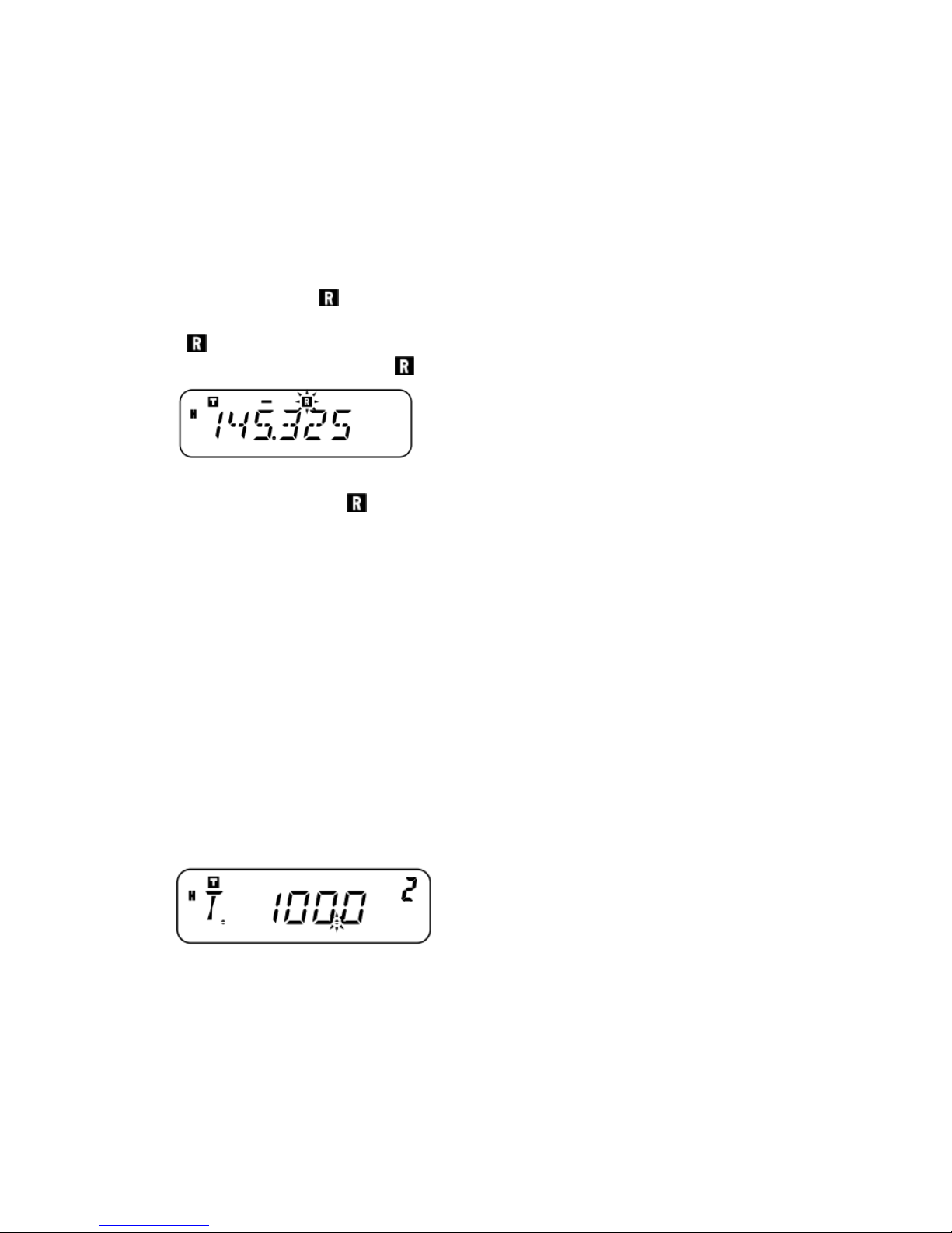
REVERSE FUNCTION
The reverse function exchanges a separate reception and transmission frequency. So, while using a
repeater, you can manually check the strength of a signal that you receive directly from the other
station. If the station’s signal is strong, both stations should change to a simplex frequency and
free up the repeater.
TO REVERSE THE TRANSMISSION AND RECEPTION FREQUENCIES
Press [REV] to switch the Reverse function ON (or OFF).
“R” appears when the function is ON.
Note:
You can turn the Reverse function ON when you are operating in Simplex Mode. However, it does
not change the Transmission/Reception frequencies.
If pressing [REV] places the reception frequency outside the allowable range, an error tone sounds
and the function does not operate.
Page 31
If pressing [REV] places the transmission frequency outside the allowable range, pressing MIC
[PTT] causes an error tone to sound and transmission is inhibited.
You cannot switch Reverse ON or OFF while transmitting.
AUTOMATIC SIMPLEX CHECK (ASC)
While using a repeater, the ASC function periodically checks the strength of the signal you are
receiving from the other station. If the station’s signal is strong enough to allow direct contact
without a repeater, the “ ” indicator starts blinking.
Press [REV] (1s) to switch the function ON (or OFF).
•“ ” appears when the function is ON.
• While direct contact is possible, “ ” blinks.
Note:
Pressing [PTT] causes the“ ”icon to quit blinking.
ASC can be activated while operating in Simplex Mode. However, it does not change the
Transmission/Reception frequencies.
ASC does not function while scanning.
Activating ASC while using Reverse switches Reverse OFF.
If you recall a Memory Channel or the Call Channel that contains a Reverse ON status, ASC will
be switched OFF.
ASC causes received audio to be momentarily intermitted every 3 seconds.
TONE FREQUENCY ID SCAN
This function scans through all tone frequencies to identify the incoming tone frequency on a
received signal. You can use this function to determine which tone frequency is required by
accessing your local repeater.
1 Press [F], [MENU] and turn the Tuning control to select Menu No. 2 (T).
2 Press [MENU] (1s) to start the Tone Frequency ID Scan.
• When the transceiver receives a signal, scan starts. The decimal point blinks during scan.
• While the transceiver is receiving a signal during Tone Frequency ID Scan, the signal is emitted
from the speaker.
•To reverse the scan direction, turn the Tuning control.
•To quit the function, press any key.
•When the tone frequency is identified, a beep sounds and the identified frequency blinks.
Page 32
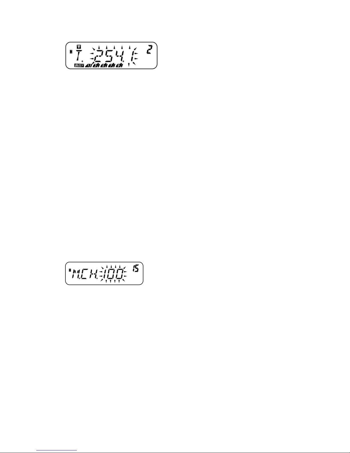
3 Press [MENU] to program the identified tone frequency in place of the current tone frequency or
press any other key to exit the Tone Frequency ID Scan.
Turn the Tuning control while the identified tone frequency is blinking to resume scanning.
4 Press any key other than [MENU] to exit Menu Mode.
Note:
Some repeaters do not re-transmit the access tone in the downlink signal. In this case, check the
other station’s uplink signal to detect the repeater access tone.
The transceiver continues to check the Weather Alert Channel and Priority Channel during Tone
Frequency ID Scan.
MEMORY CHANNELS
In Memory Channels, you can store frequencies and related data that you frequently use so that
you do not need to reprogram that data every time. You can quickly recall a programmed channel
through simple operation. A total of 200 Memory Channels (100 when using the Memory Name
function) are available for storing frequencies, modes, and other operating conditions.
NUMBER OF MEMORY CHANNELS
The transceiver must be configured to either 200 Memory Channels without using the Memory
Name function or 100 Memory Channels with the Memory Name function (default).
To change the Memory Channel capacity:
1 Press [F], [MENU] and turn the Tuning control to select Menu No. 15 (M.CH).
2 Press [MENU] and turn the Tuning control to select either “100” (default) or “200”.
3 Press [MENU].
“SURE?” appears.
4 Press [MENU] to accept or press any other key to cancel.
Note:
If you change the Memory Channel capacity from 200 channels to 100 channels after having
stored data in channels 100 to 199, all Memory Channel data in channels 100 to 199 will be
erased.
If you change the Memory Channel capacity from 100 channels to 200 channels after storing
Memory Names in those channels, the Memory Name data will be erased.
SIMPLEX & REPEATER OR ODD-SPLIT MEMORY CHANNEL
You can use each Memory Channel as a simplex & repeater channel or an odd-split channel.
Store only 1 frequency to use as a simplex & repeater channel or 2 separate frequencies to use as
Page 33
an odd-split channel. Select either application for each channel depending on the operations you
have in mind.
Simplex & repeater channels allow:
• Simplex frequency operation
• Repeater operation with a standard offset (if an offset direction is stored)
Odd-split channels allow:
Repeater operation with a non-standard offset
Note: Not only can you store data in Memory Channels, but you can also overwrite existing data
with new data.
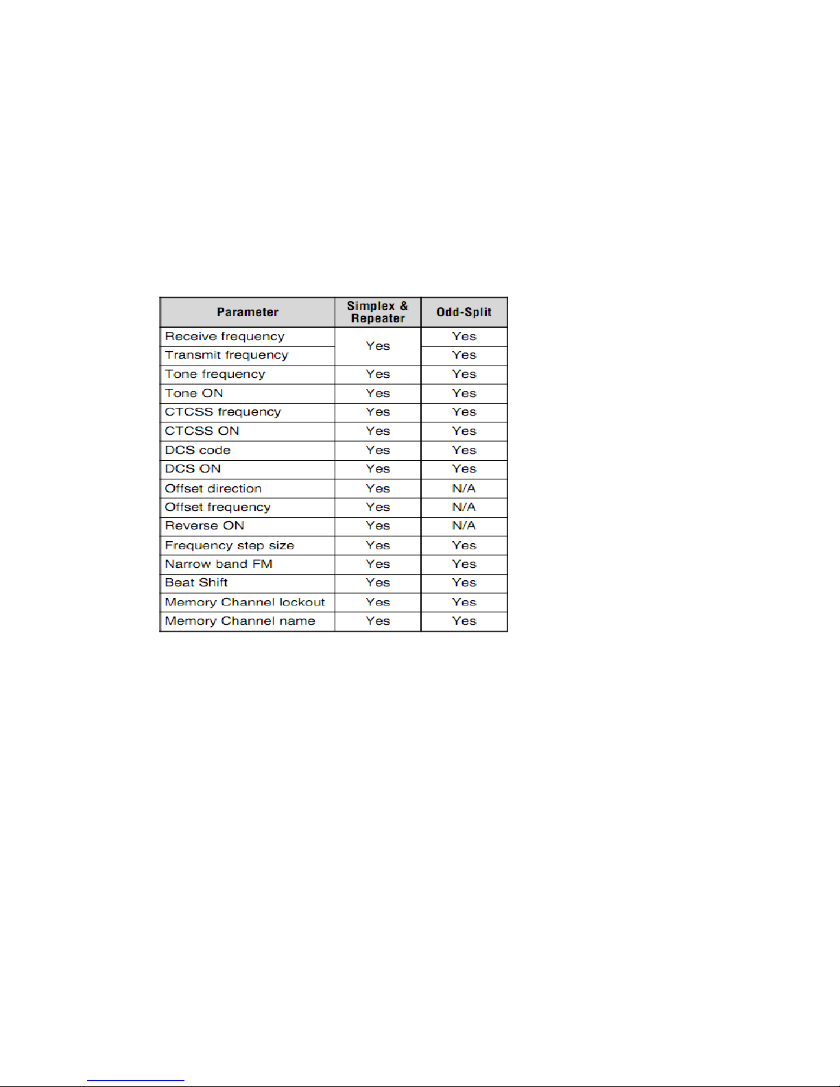
The data listed below can be stored in each Memory Channel:
Yes: Can be stored in memory.
N/A: Cannot be stored in memory.
Note:
Memory Channel Lockout cannot be set to the Program Scan Memory (L0/U0 ~ L2/U2), the
Priority Channel (Pr), or the Weather Alert Channel (AL).
Tone, CTCSS, and DCS are automatically turned OFF when setting up the Weather Alert Channel
(AL).
STORING SIMPLEX FREQUENCIES OR STANDARD REPEATER FREQUENCIES
1 Press [VFO].
2 Turn the Tuning control to select your desired frequency.
You can also directly enter a desired frequency using the keypad {page 13}.
3 If storing a standard repeater frequency, select the following data:
•Offset direction {page 23}
•Tone function, if necessary {page 24}
•CTCSS/ DCS function, if necessary {pages 43, 45}
Page 34
If storing a simplex frequency, you may select other related data (CTCSS or DCS settings, etc.).
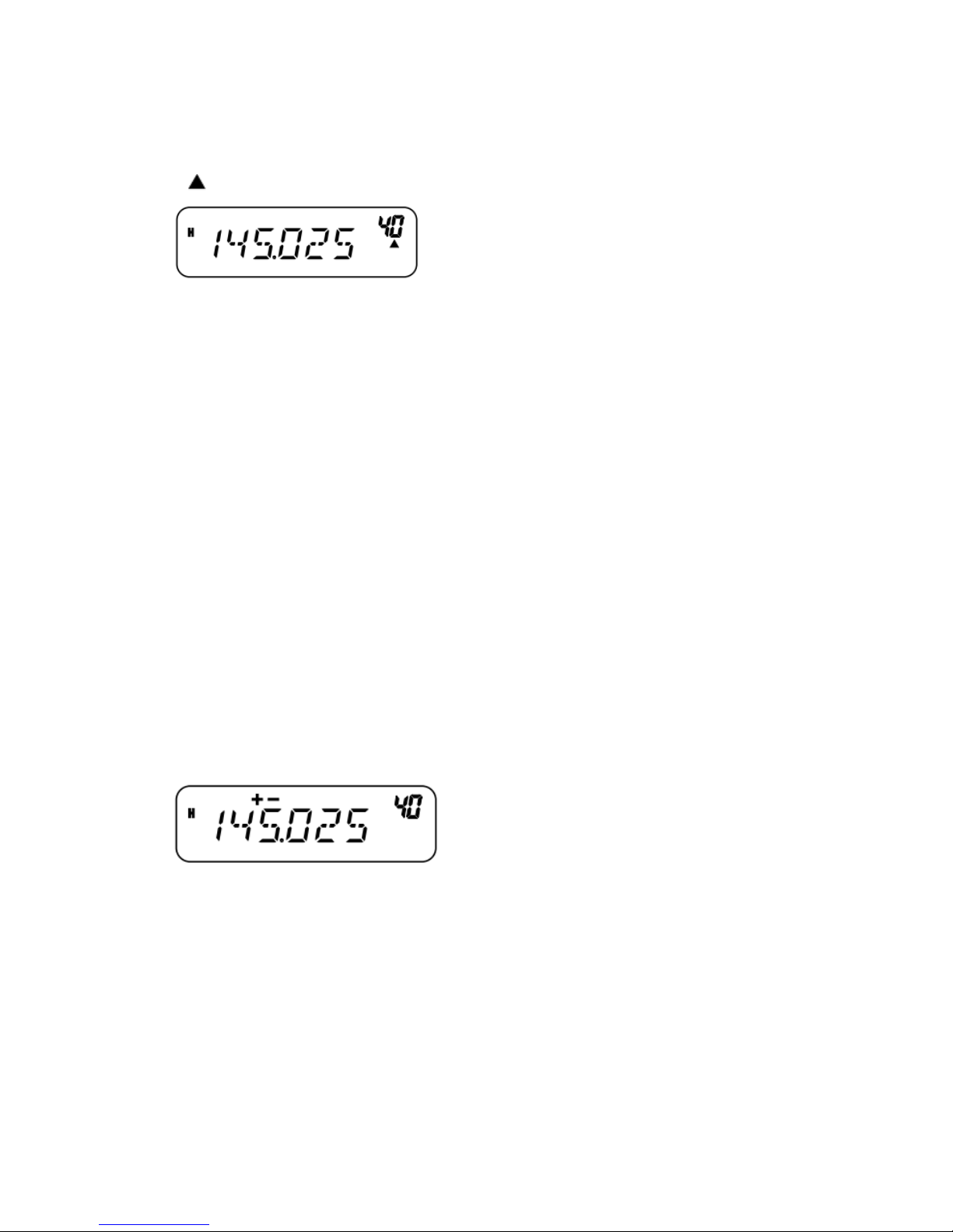
4 Press [F].
•A Memory Channel number appears and blinks.
•“ ”appears if the channel contains data.
• Memory Channel numbers L0/U0 ~ L2/U2 {page 38}, Pr {page 38}, and AL (Weather Alert)
{page 35} (K market models only) are reserved for other functions.
5 Turn the Tuning control or press MIC [UP]/[DWN] to select the Memory Channel in which you
want to store the data.
6 Press [MR] to store the data into the channel.
STORING ODD-SPLIT REPEATER FREQUENCIES
Some repeaters use a pair of reception and transmission frequencies with a non-standard offset.
If you store 2 separate frequencies in a Memory Channel, you can operate on those repeaters
without programming the offset frequency and direction.
1 Store the desired reception frequency and related data by following steps 1 to 6 given for
simplex or standard repeater frequencies {page 29}.
2 Turn the Tuning control or press MIC [UP]/[DWN] to select your desired transmission
frequency.
3 Press [F].
4 Turn the Tuning control or press MIC [UP]/[DWN] to select the pre-programmed reception
Memory Channel in which you want to store the data.
5 Press [MR] (1s).
The transmission frequency is stored in the Memory Channel.
Note:
When you recall an odd-split Memory Channel, “+”and “–”appear on the display. To confirm
the transmission frequency, press [REV].
Transmit offset status and reverse status are not stored in odd-split Memory Channels.
RECALLING A MEMORY CHANNEL
USING THE TUNING CONTROL
1 Press [MR] to enter Memory Recall mode.
The Memory Channel last used is recalled.
Page 35
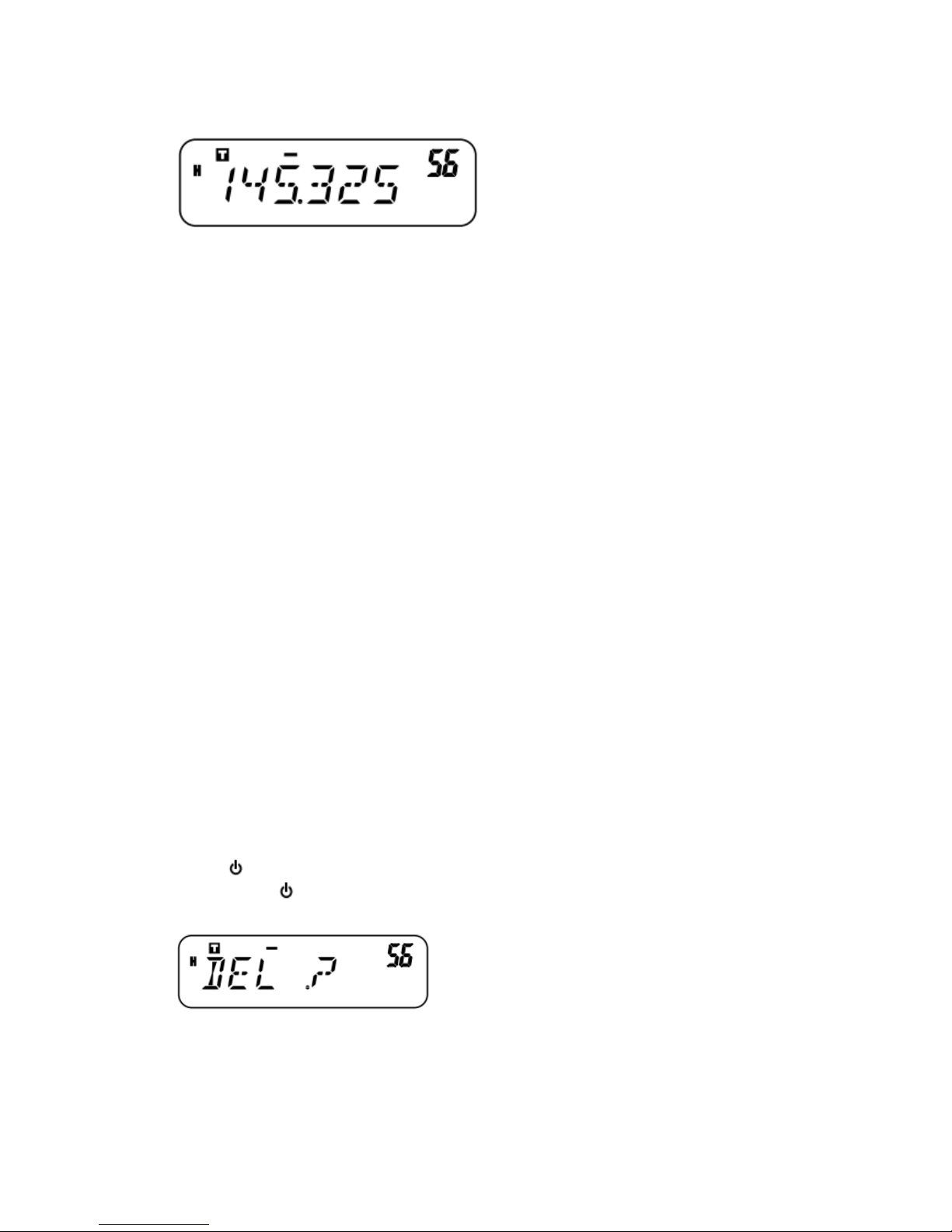
2 Turn the Tuning control to select your desired Memory Channel.
•You cannot recall an empty Memory Channel.
•To restore VFO mode, press [VFO].
USING THE MICROPHONE KEYPAD
You can also recall a Memory Channel by entering a desired Memory Channel number with the
Microphone keypad.
1 Press [MR] to enter Memory Recall mode.
2 Press the Microphone key assigned the ENTER function.
3 Enter the channel number using the Microphone keypad.
• For single-digit channel numbers, enter “0” first or press MIC Enter after entering the channel
number.
• For two-digit channel numbers that begin with “1”, press MIC Enter after entering the channel
number.
Note:
You cannot recall an empty Memory Channel. An error beep sounds.
You cannot recall the Program Scan Memory Channels (L0/U0 ~ L2/U2), the Priority Channel
(Pr), and the Weather Alert Channel (AL) (K market models only) using the numeric keypad.
When you recall an odd-split memory channel,“+”and“–”appear on the display. Press [REV]
to display the transmission frequency.
After recalling a Memory Channel, you may modify data such as Narrow Band, Tone, or CTCSS.
However, these settings are cleared once you select another channel or the VFO Mode. To
permanently store the data, overwrite the channel contents.
CLEARING A MEMORY CHANNEL
To erase an individual Memory Channel:
1 Recall the Memory Channel you want to erase.
2 Press [ ] (Power) (1s) to switch the transceiver OFF.
3 Press [MR] + [ ] (Power).
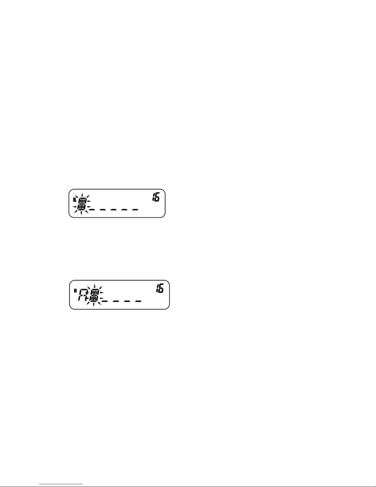
An erase confirmation message appears.
4 Press [MR] to erase the channel data.
•The contents of the Memory Channel are erased.
•To quit clearing the Memory Channel, press any key other than [MR].
Note:
Page 36
You can also clear the Priority Channel, the AL Channel, and L0/U0 ~ L2/U2 data. (The Call
Channel cannot be cleared.)
To clear all Memory Channel contents at once, perform Full Reset {page 62}.
You cannot clear channels while in Channel Display Mode.
NAMING A MEMORY CHANNEL
You can name Memory Channels using up to 6 alphanumeric characters. When you recall a named
Memory Channel, its name appears on the display in place of the stored frequency. Names can be
call signs, repeater names, cities, names of people, etc. In order to use the Memory Name function,
the Memory Channel capacity must be set to 100 channels. To change the Memory Channel
capacity from 200 to 100, access Menu No. 15 (M.CH) {page 28}.
1 Press [MR] and turn the Tuning control to recall your desired Memory Channel.
2 Press [F], [MENU] and turn the Tuning control to select Menu No.16 (M.NAME).
3 Press [MENU]
A blinking cursor appears.
4 Turn the Tuning control to select a desired alphanumeric character.
•You can enter the following alphanumeric characters: 0~9, A~Z, – (hyphen), /(slash), and space.
• Rather than using the Tuning control, you can use the MIC keypad (keypad models only) to
enter alphanumeric characters {page 59}.
5 Press [MR].
•The cursor moves to the next digit.
•To move to the previous digit, press [VFO]. To delete the character at the current cursor position,
press [F].
6 Repeat steps 4 and 5 to enter up to 6 digits.
7 Press [MENU] to complete the entry.
•Press any key other than [MR], [VFO], [F], and [MENU] to cancel the entry.
•To complete an entry of less than 6 characters, press [MENU] two times.
8 Press any key other than [MENU] to exit Menu Mode.
After storing a Memory Name, the Memory Name appears in place of the operating frequency.
However, you can still display the operating frequency, if desired. To display the frequency rather
than Memory Name, access Menu No. 17 (MDF) and select “FRQ”. This menu toggles the display
mode between the Memory Name (“MN”) and frequency display (“FRQ”).
Note:
You cannot name the Call Channel {page 34}.
You cannot assign a Memory Name to a channel that does not contain data.
Page 37
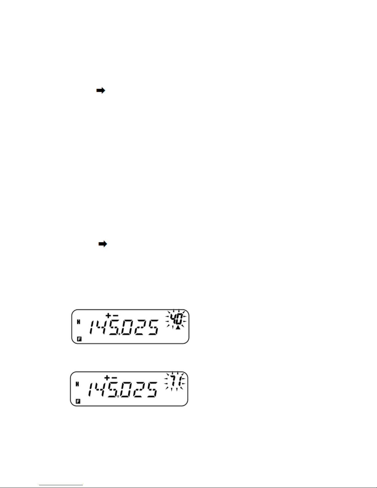
You can overwrite stored names by repeating steps 1 to 8.
The stored name is erased when you clear the Memory Channel data.
MEMORY CHANNEL TRANSFER
MEMORY VFO TRANSFER
After retrieving frequencies and associated data from Memory Recall Mode, you can copy the
data to the VFO. This function is useful, for example, when the frequency you want to monitor is
near the frequency stored in a Memory Channel.
1 Press [MR], then turn the Tuning control or press MIC [UP]/[DOWN] to recall the desired
Memory Channel.
Alternatively, press [CALL] to select the Call Channel.
2 Press [F], [VFO] to copy the Memory Channel data to the VFO.
Note:
On odd-split channels, the above operation copies only the reception frequency to the VFO (not
the transmission frequency). To copy the transmit frequency of an odd-split channel, press [REV]
before performing the transfer.
You can also transfer the Program Scan memory channels (L0/U0 ~ L2/U2), the Priority Channel
(Pr), and the Weather Alert Channel (AL) (K market models only) to the VFO.
Lockout status and Memory Names will not be copied from a Memory Channel to the VFO.
CHANNEL CHANNEL TRANSFER
You can copy channel information from one Memory Channel to another. This function is useful
when storing frequencies and associated data that you temporarily change in Memory Recall
Mode.
1 Press [MR], then turn the Tuning control or press MIC [UP]/[DWN] to recall the desired
Memory Channel.
2 Press [F].
3 Select the Memory Channel where you would like the data copied by using the Tuning control
or pressing MIC [UP]/[DOWN].
4 Press [MR].
Page 38
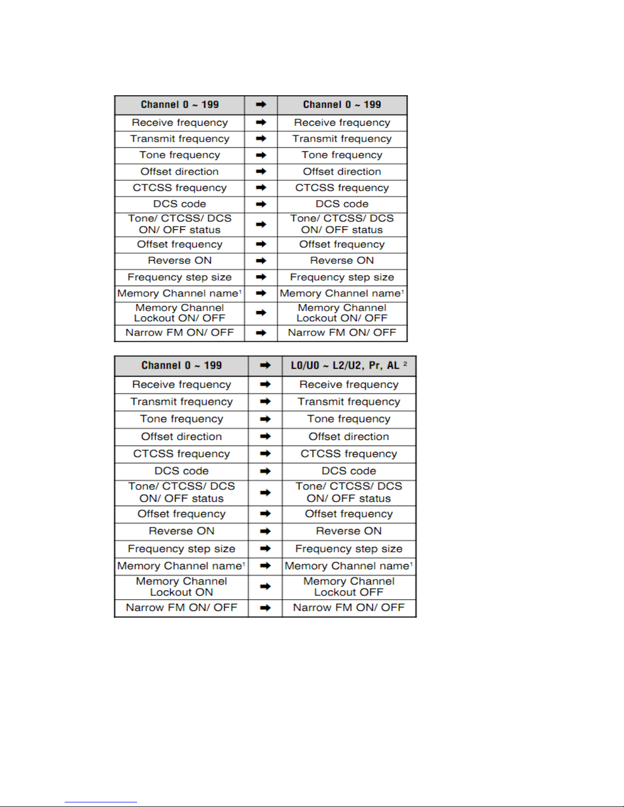
The tables below illustrate how data is transferred between Memory Channels.
1 When “100” is selected in Menu No.15 (M.CH).
2 The AL Channel is available for K market models only.
Note:
When transferring an odd-split channel, the Reverse status, Offset direction, and Offset frequency
are not transferred {pages 23, 26}.
Tone, CTCSS, and DCS are automatically turned OFF when transferring data to the Weather Alert
Channel (AL).
Page 39
CALL CHANNEL
Call Channel default settings:
•On E market models, pressing [CALL] causes the transceiver to transmit a 1750 Hz tone {page
25}.
•On other market models, pressing [CALL] changes the transceiver to the Call Channel.
The Call Channel can be recalled instantly no matter what frequency the transceiver is operating
on. For instance, you may use the Call Channel as an emergency channel within your group. In
this case, Call Scan {page 40} will be useful.
The default Call Channel frequencies will be different according to market models.
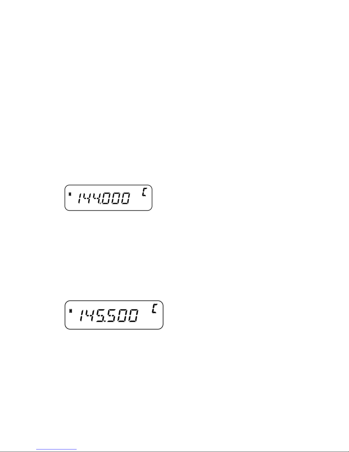
•M3 market: 144.oooMHZ
•C market: 410.000MHZ
•C2 market: 450.000MHZ
Note: Unlike Memory Channels 0 to 199, the Call Channel cannot be cleared.
RECALLING THE CALL CHANNEL
1 Press [CALL] to recall the Call Channel.
•The Call Channel frequency and “C” appear.
•To return to the previous frequency, press [CALL] again.
REPROGRAMMING THE CALL CHANNEL
1 Select your desired frequency and related data (Tone, CTCSS, DCS, or offset direction, etc.).
• When you program the Call Channel as an odd-split channel, select a reception frequency first.
2 Press [F].
A Memory Channel number appears and blinks.
3 Turn the Tuning control or press MIC [UP]/[DWN] to select the Call Channel (“C”).
4 Press [MR].
•The selected frequency and related data are stored in the Call Channel.
To also store a separate transmit frequency, continue with the following steps:
5 Select the desired transmission frequency.
6 Press [F].
7 Turn the Tuning control or press MIC [UP]/[DWN] to select the Call Channel (“C”).
8 Press [MR] (1s).
• The separate transmission frequency is stored in the call channel.
Note:
When you recall an odd-split Call Channel,“+”and“–”appear on the display.
Transmit offset status and Reverse status are not stored in an odd-split Call Channel.
Page 40
WEATHER ALERT (K MARKET MODELS ONLY)
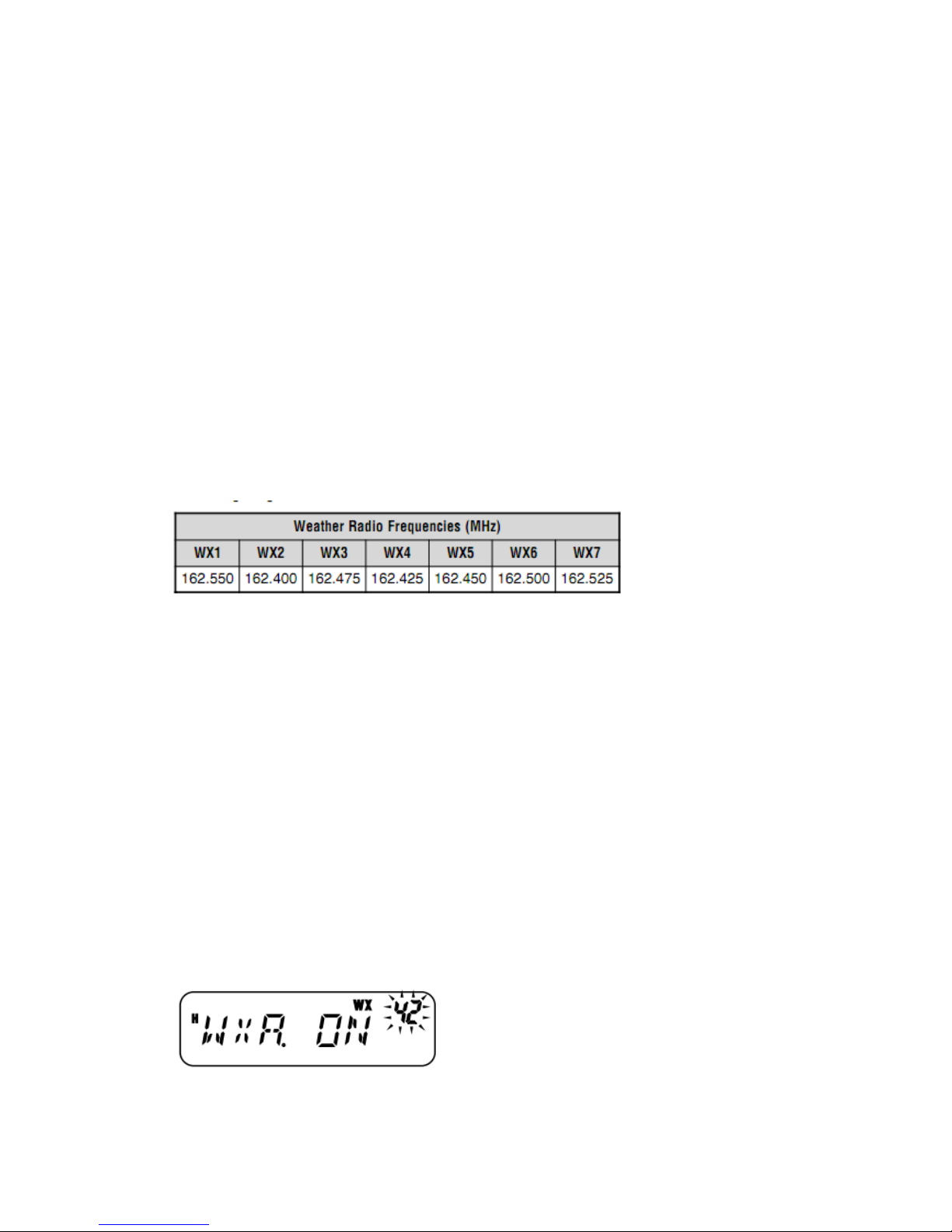
Any of the NOAA Weather Radio channels can be programmed to the AL memory channel of the
transceiver. The transceiver can be configured to check the NOAA Weather Alert tone (1050 Hz)
and will automatically alert you by recalling and monitoring the Weather Radio frequency when
the Weather Alert tone is being broadcasted, and the “WX” icon will blink.
PROGRAMMING THE WEATHER RADIO FREQUENCY
The transceiver is preprogrammed to 162.550 MHz (WX1). You can store a different frequency to
the AL channel to use this function. Refer to the NOAA channel frequency directory for your local
weather channel frequency before you use the Weather Alert function. The latest Weather Radio
information can be obtained from http://www.nws.noaa.gov/nwr/.
1 Press [VFO].
2 Select your local NOAA Weather Radio channel frequency using the Tuning control or MIC
[UP]/[DWN].
3 Press [F].
•A Memory Channel number appears and blinks.
4 Turn the Tuning control or press MIC [UP]/[DWN] to select the Alert Channel (“AL”).
5 Press [MR].
Note:
When you perform Full Reset {page 62}, the Weather Radio frequency recovers the factory
default frequency (162.550 MHz).
When you clear the Weather Radio (AL) Channel {page 31} (the same as clearing a Memory
Channel), the factory default frequency (162.550 MHz) will be recovered.
The Weather Radio (AL) Channel can be programmed with a Channel Name {page 31}.
You can also transfer the AL Memory Channel data to the VFO or another Memory Channel.
ENABLING A WEATHER ALERT
You can monitor the Weather Radio frequency continuously or in the background while receiving
on another frequency.
To monitor the Weather Radio frequency continuously:
1 Press [F], [MENU] and turn the Tuning control to select Menu No. 42 (WXA).
2 Press [MENU] and turn the Tuning control to select“ON” or “OFF” (default).
3 Press [MENU] to store the setting.
“WX” appears on the display.
Page 41
4 Press any key other than [MENU] to exit Menu Mode.
•The transceiver automatically changes to the AL channel.
•The Tone, CTCSS, and DCS functions cannot be configured to the AL channel.
•Priority Scan is set to OFF automatically when the Weather Alert function is turned ON.
5 To exit Weather Alert Mode, press [MENU], select Menu No. 42 (WXA), and set it to “OFF”
(default).
To monitor another frequency while monitoring the Weather Radio in the background:
1 Perform above step 1 ~ 4.
2 Press [VFO] or [MR] and turn the Tuning control to select another frequency or Memory
Channel.
“WX” remains on the LCD.
3 When the Weather Alert tone is being broadcasted, the transceiver automatically switches to the
AL channel.
“WX” blinks.
4 To exit Weather Alert Mode, press [MENU], select Menu No. 42 (WXA), and set it to “OFF”.
Note:
The transceiver checks the Weather Alert tone once every second while you are monitoring
another frequency or channel.
When a 1050 Hz tone is detected, the display will change to the AL channel, the Weather Alert
tone sounds, and the “WX” icon blinks. Squelch remains open until the frequency is changed or
the transceiver power is turned OFF.
If the transceiver is transmitting or receiving a signal on another frequency, the Weather Alert
function temporarily pauses.
Turning the Beep function“OFF”does not disable the Weather Alert tone.
You cannot transmit on the AL channel while the Weather Alert function is ON.
CHANNEL DISPLAY
While in this mode, the transceiver displays only Memory Channel numbers (or Memory Names if
they have been stored), instead of frequencies.
1 With the transceiver power OFF, press [REV]+[ ](Power) to turn the power ON.
The transceiver displays the Memory Channel numbers in place of the operating frequencies.
2 Turn the Tuning control or press MIC [UP]/[DWN] to select your desired Memory Channel
number. While in Channel Display mode, you cannot activate the following functions:
•VFO Mode
•VFO Scan
•Call/VFO Scan
•MHz Scan
•Scan Direction
Page 42
•Memory Store
•Memory to VFO Transfer
•Memory to Memory Transfer
•Clear Memory Channel
•VFO Reset
•Full Reset
• MHz Step
•Selection for Tone and Selective Call
•Auto Simplex Checker
•Menu Mode
To recover normal operation, turn the transceiver power OFF and press [REV]+[ ] (Power)
again.
Note:
To enter the Channel Display Mode, you must have at least one Memory Channel that contains
data.
If the Memory Channel contains a Memory Name, the Memory Name is displayed in place of
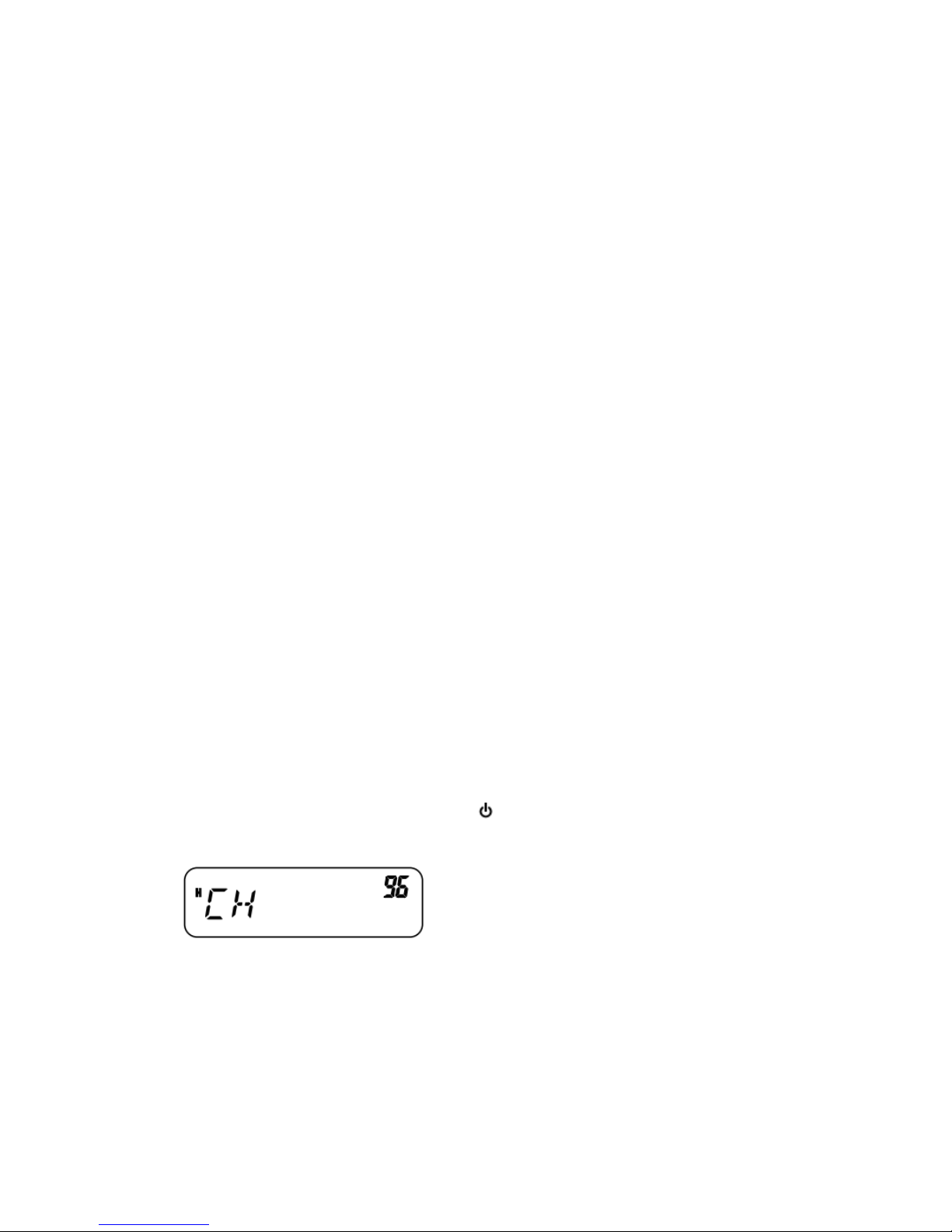
“CH”.
SCAN
Scan function is used for auto monitoring of the needed frequencies. By acquaint yourself with all
types of scan, you will increase your operating efficiency.
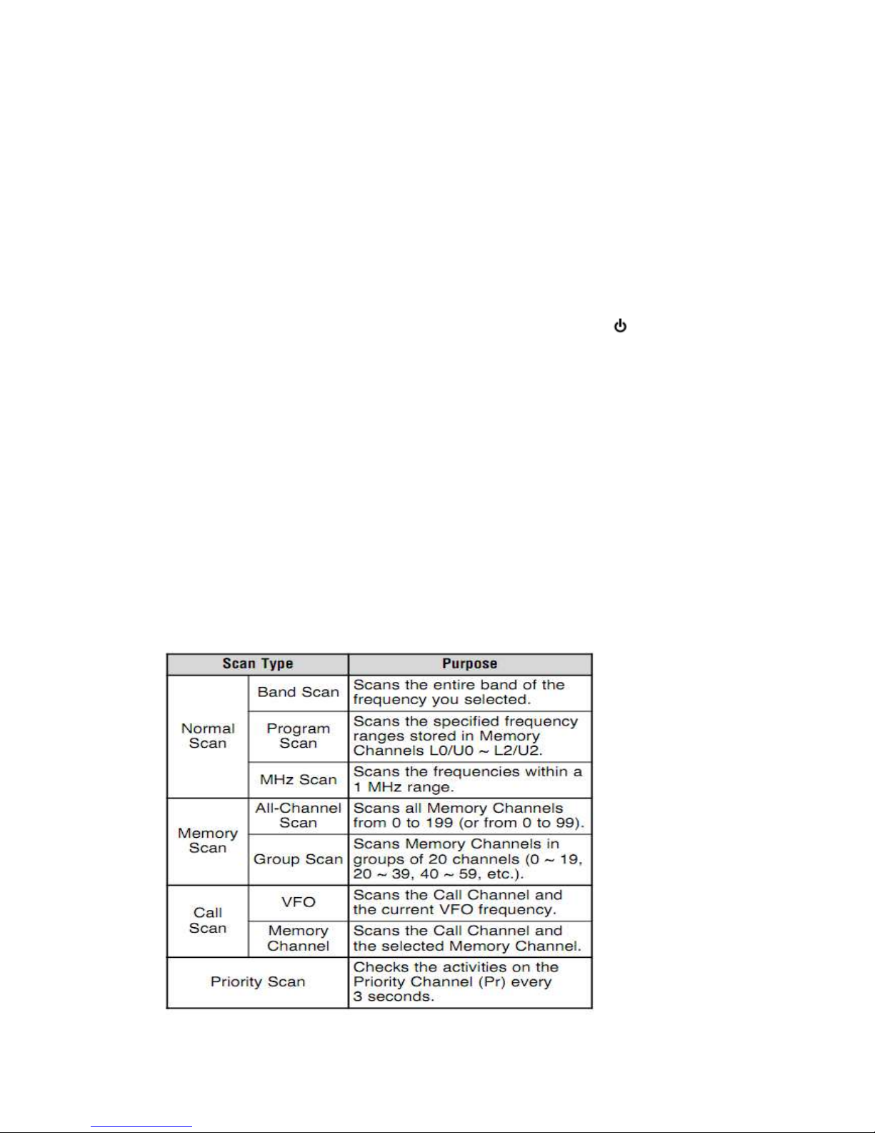
This transceiver provides the following types of scans.
Page 43

Note:
When the CTCSS or DCS function is activated, the transceiver stops at a busy frequency and
decodes the CTCSS tone or DCS code. If the tone or code matches, the transceiver unmutes.
Otherwise, it resumes scanning.
Press and hold the MIC PF key programmed as MONI {page55} to pause scan in order to monitor
the scanning frequency. Release the key to resume scanning.
Pressing and holding MIC [PTT] causes scan to stop (excluding Priority Scan).
While scanning, you can change the scan frequency direction by turning the Tuning control or
using the MIC [UP]/[DWN] keys.
Starting scan switches OFF the Automatic Simplex Check (ASC) {page 26}.
Adjust the Squelch level before using Scan {page14}. Selecting a Squelch level too low could
cause Scan to stop immediately.
NORMAL SCAN
When you are operating the transceiver in VFO Mode, 3 types of scanning are available: Band
Scan, Program Scan, and MHz Scan.
BAND SCAN
The transceiver scans the entire band of the frequency you selected. For example, if you are
operating and receiving at 144.525 MHz, it scans all the frequencies available for the VHF band.
(Refer to receiver VFO frequency range in the specifications {page 67}.) When the current VFO
receive frequency is outside the Program Scan frequency range {below}, the transceiver scans the
entire frequency range available for the current VFO.
1 Press [VFO] and turn the Tuning control or press MIC [UP]/[DWN] to select a frequency
outside of the Program Scan frequency range.
2 Press [VFO] (1s) to start Band Scan.
•Scan starts from the current frequency.
•The 1 MHz decimal blinks while scanning is in progress.
3 Press any key other than [F] or [ ] (Power) to stop Band Scan.
Note:
The transceiver scans the frequency range that is stored in Menu No. 7 (P.VFO) {page 57}.
If you select a frequency within the L0/U0 ~ L2/U2 range in step 2, Program Scan starts.
PROGRAM SCAN
You can limit the scanning frequency range. There are 3 memory channel pairs (L0/U0 ~ L2/U2)
available for specifying the start and end frequencies. Program Scan monitors the range between
the start and end frequencies that you have stored in these Memory Channels. Before performing
Program Scan, store the Program Scan frequency range to one of the Memory Channel pairs
(L0/U0 ~ L2/U2).
Storing a Program Scan Frequency Range
1 Press [VFO] and turn the Tuning control or press MIC [UP]/[DWN] to select your desired start
frequency.
2 Press [F].
A Memory Channel number appears and blinks.
Page 44
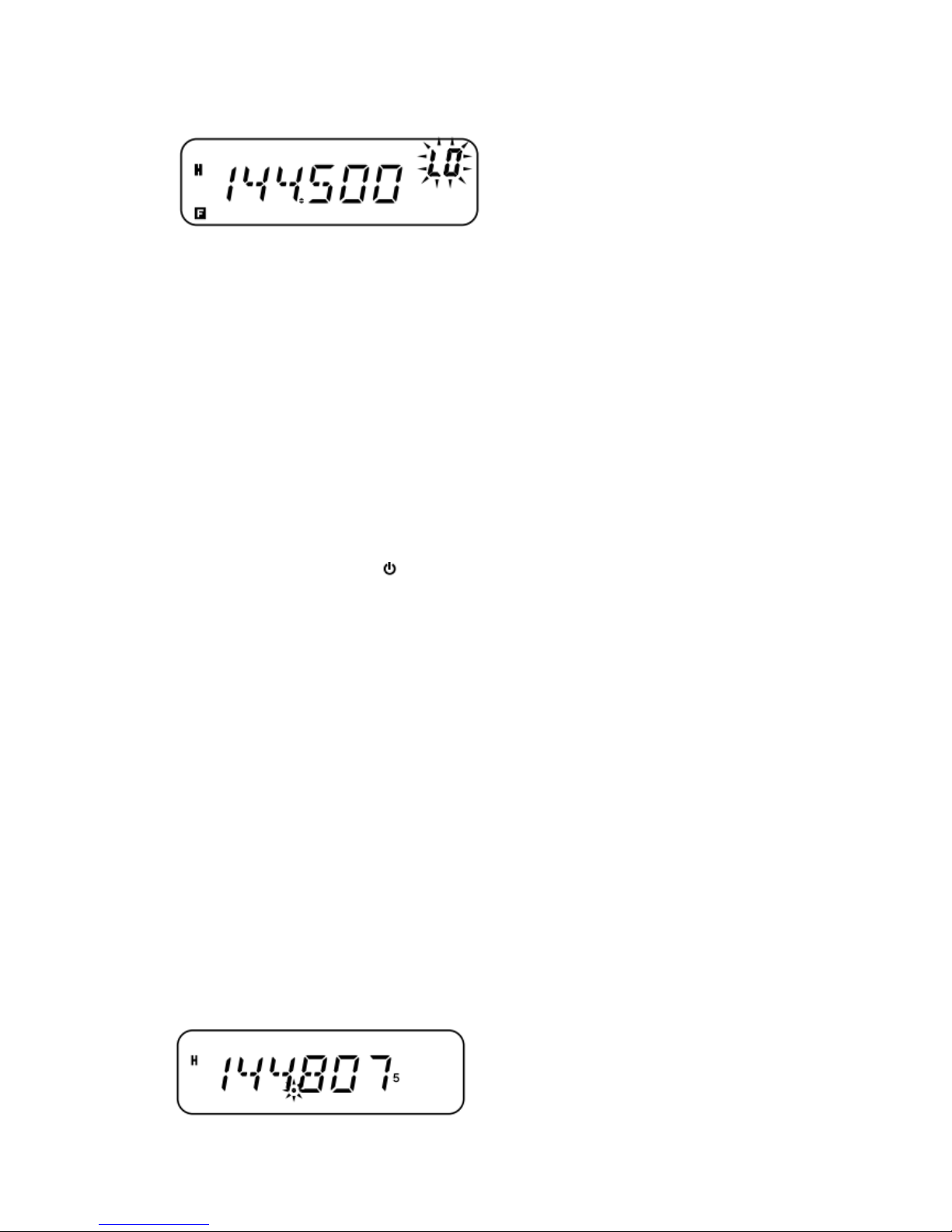
3 Turn the Tuning control or press MIC [UP]/[DWN] to select a Memory Channel from L0 ~ L2.
4 Press [MR] to store the start frequency in the Memory Channel.
5 Turn the Tuning control to select your desired end frequency.
6 Press [F].
7 Turn the Tuning control or press MIC [UP]/[DWN] to select a matching Memory Channel from
U0 ~ U2.
For example, if you have selected “L0” in step 3, select Memory Channel “U0”.
8 Press [MR] to store the end frequency in the Memory Channel.
PROGRAM SCAN
1 Press [VFO] and turn the Tuning control to select a frequency within the frequency range of
Memory Channel L0/U0 ~ L2/U2.
2 Press [VFO] (1s) to start Program Scan.
•Scan starts from the current frequency.
•The 1 MHz decimal blinks while scanning is in progress.
3 Press any key other than [F] or [ ] (Power) to stop Program Scan.
Note:
The transceiver stops scanning when it detects a signal.
If more than 2 Program Scan channel pairs are stored and overlaps the frequency range among the
pairs, the smaller Program Scan Memory Channel number has priority.
If the step size of the current VFO frequency is different from that of the programmed frequencies,
VFO Scan begins instead of Program Scan.
To perform Program Scan, the “L” channel must be lower than the “U” channel. Otherwise, Band
Scan starts {page 37}.
MHZ SCAN
MHz Scan allows you to scan an entire 1 MHz frequency range within the current VFO frequency.
1 Press [VFO] and turn the Tuning control or press MIC [UP]/[DWN] to select a frequency in
which to perform MHz Scan.
If you want to scan the entire 145 MHz frequency, select any frequency between 145.000 and
145.9975 MHz (for example, select 145.650 MHz). Scan will operate between 145.000 MHz and
145.9975 MHz. (The upper frequency limit depends on the current frequency step size.)
2 Press [MENU] (1s) to start MHz Scan.
•Scan starts from the current frequency.
•The 1 MHz decimal blinks while scanning is in progress.
Page 45

3 Press any key other than [F] or [ ] (Power) to stop MHz Scan.
MEMORY SCAN
Memory Scan monitors Memory Channels in which you have stored frequencies.
ALL-CHANNEL SCAN
The transceiver scans all of the Memory Channels in which you have stored frequencies.
1 Press [MR] (1s).
• Scan starts from the last Memory Channel number and ascends up through the channel numbers
(default).
•To jump to a desired channel while scanning, quickly turn the Tuning control.
•To reverse the scan direction, turn the Tuning control or press MIC [UP]/[DWN].
2 Press any key other than [F] or [ ] (Power) to stop All-Channel Scan.
Note:
You must have 2 or more Memory Channels that contain data, excluding special function Memory
Channels (L0/U0 ~ L3/U3, Pr, and AL).
You can perform Memory Scan while in CH Display Mode. While Scan is paused, the Channel
number blinks.
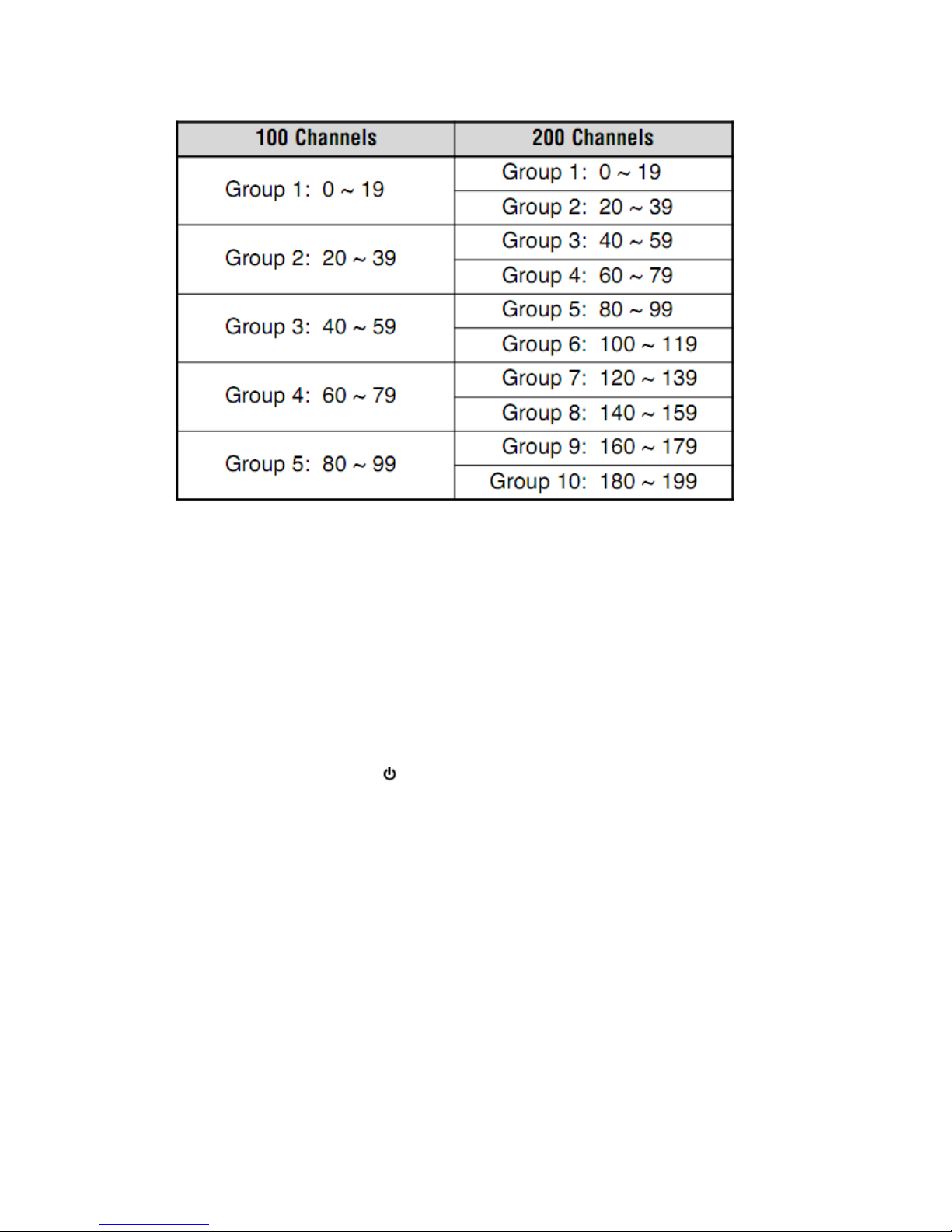
GROUP SCAN
The transceiver scans Memory Channels in groups of 20 channels. When Menu No. 15 (M.CH) is
set to 100, the transceiver uses 5 groups of 20 channels. When Menu No. 15 (M.CH) is set to 200,
the transceiver uses 10 groups of 20 channels.
1 Press [MR] and turn the Tuning control or press MIC [UP]/[DWN] to select a Memory Channel
in the range of the group you want to scan.
2 Press [MENU] (1s).
•Scan starts from the selected Memory Channel number and ascends up through the channel
numbers (default).
•To reverse the scan direction, turn the Tuning control or press MIC [UP]/[DWN].
3 Press any key other than [F] or [ ] (Power) to stop Group Scan.
Note: You must have 2 or more Memory Channels in the selected group that contains data.
Page 46
CALL SCAN
You can alternate between monitoring the Call Channel and the current operating frequency.
1 Select the frequency (in VFO or Memory Recall Mode) you want to monitor.
•In VFO Mode, turn the Tuning control or press MIC [UP]/[DWN] to select the desired frequency.
•In Memory Recall Mode, turn the Tuning control or press MIC [UP]/[DWN] to select the
Memory Channel you want to monitor.
2 Press [CALL] (1s) to start the Call Scan.
•The Call Channel and the selected VFO frequency or memory channel are monitored.
•The 1 MHz decimal blinks while scanning is in progress.
3 Press any key other than [F] or [ ] (Power) to stop Call Scan.
Note:
You must configure the CALL key function to“CALL”(Menu No. 19) prior to using Call Scan.
Otherwise, a 1750 Hz tone will be transmitted.
You can perform Call Scan even if the recalled Memory Channel has been locked out {page 42}.
PRIORITY SCAN
You may sometimes want to check your favorite frequency activities while monitoring other
frequencies. In this case, use the Priority Scan function. Priority Scan checks the activities of the
Priority Channel every3 seconds. If the transceiver detects a signal on the Priority Channel, it
recalls the frequency to the VFO.
PROGRAMMING A PRIORITY CHANNEL
1 Press [VFO] and turn the Tuning control or press MIC [UP]/[DWN] to select your desired
Page 47
Priority Channel frequency.
2 Select selective call functions, if necessary.
3 Press [F].
The Memory Channel number appears and blinks.
4 Turn the Tuning control or press MIC [UP]/[DWN] to select the Priority Channel (“Pr”).
5 Press [MR] to store the data onto the Priority Channel.
USING PRIORITY SCAN
1 Press [F], [MENU] and turn the Tuning control to select Menu No. 12 (PRI).
2 Press [MENU] and turn the Tuning control to select“ON” or “OFF” (default).
3 Press [MENU] to store the setting or any other key to cancel.
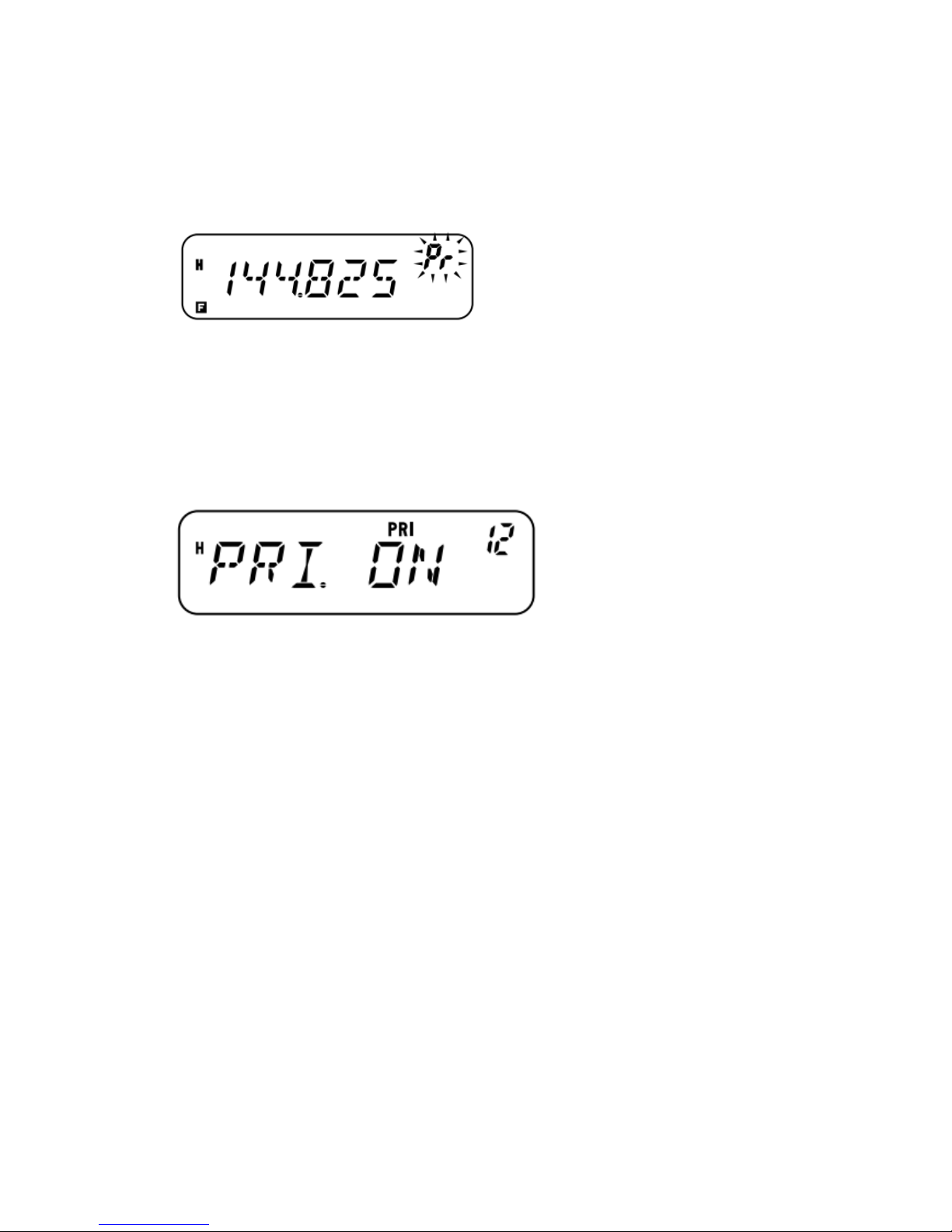
“PRI” appears.
4 Press any key other than [MENU] to exit Menu Mode.
• The transceiver checks for a signal on the Priority Channel every 3 seconds.
• When the transceiver detects a signal on the Priority Channel, “Pr” blinks and the frequency
changes to the Priority Channel.
• If you do not operate any control or key for 3 seconds after the signal drops, the transceiver
returns to the original frequency and resumes Priority Scan.
Note:
If you clear the Priority Channel {page 31}, Priority Scan stops.
Priority Scan temporarily stops while the transceiver is transmitting.
If Priority Scan is set to ON, the Weather Alert function is automatically turned OFF.
MEMORY CHANNEL LOCKOUT
You can lock out Memory Channels that you prefer not to monitor during Memory Scan or Group
Scan {page 39}.
1 Press [MR] and turn the Tuning control or press MIC [UP]/[DWN] to select the Memory
Channel to be locked out.
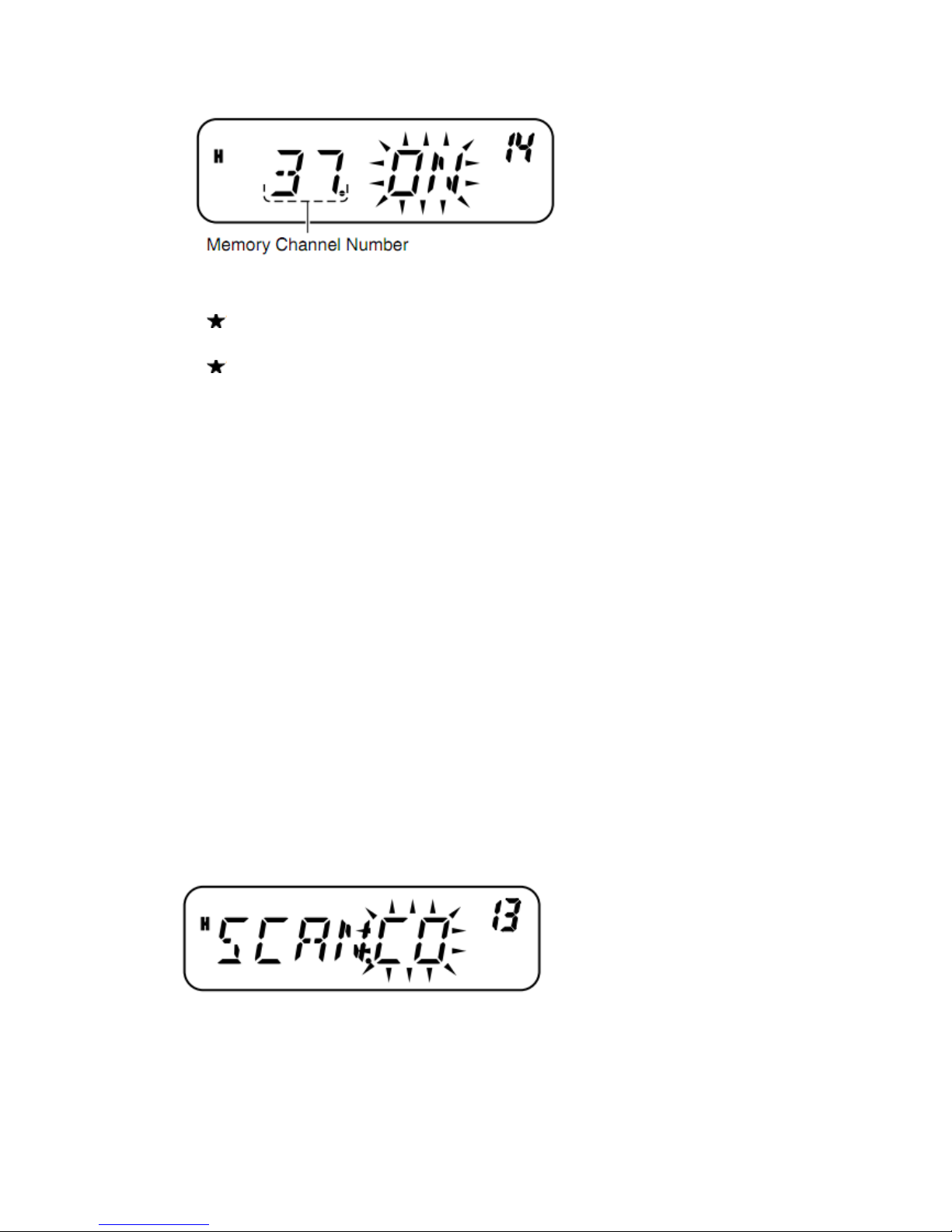
2 Press [F], [MENU] and turn the Tuning control to select Menu No. 14 (L.OUT).
3 Press [MENU] and turn the Tuning control to select“ON” or “OFF” (default).
Page 48
4 Press [MENU] to store the setting or any other key to cancel.
5 Press any key other than [MENU] to exit Menu Mode.
The “ ” icon appears below the Memory Channel number, indicating the channel is locked out.
6 To unlock the Memory Channel, repeat steps 1 ~ 5, selecting “OFF” in step 3.
The “ ” icon disappears.
Note:
The Program Scan channels (L0/U0 ~ L2/U2), Call Channel, Priority Channel (Pr), and Weather
Radio Channel (AL) (K market models only) cannot be locked out.
Even if a Memory Channel is locked out, you can perform Call Scan {page 40} between the Call
Channel and Memory Channel.
SCAN RESUME METHOD
The transceiver stops scanning at the frequency (or Memory Channel) where a signal is detected.
It then continues or stops scanning according to which Resume Mode you have selected.
•Time-Operated Mode (default)
The transceiver remains on a busy frequency (or Memory Channel) for approximately 5 seconds,
then continues to scan even if the signal is still present.
•Carrier-Operated Mode
The transceiver remains on a busy frequency (or Memory Channel) until the signal drops out.
There is a 2-second delay between signal dropout and scan resumption.
• Seek Mode
The transceiver moves to a frequency (or Memory Channel) where a signal is present and stops.
To change the scan resumption method:
1 Press [F], [MENU] and turn the Tuning control to select Menu No. 13 (SCAN).
2 Press [MENU] and turn the Tuning control to select“TO” (Time-Operated; default), “CO”
(Carrier- Operated), or “SE” (Seek) Mode.
3 Press [MENU] to store the new setting or any other key to cancel.
4 Press any key other than [MENU] to exit Menu Mode.
Note: To temporarily stop scanning and monitor weak signals, press the MIC PF key assigned the
MONI function {page 55}. Press the MONI key again to resume scanning.
Page 49
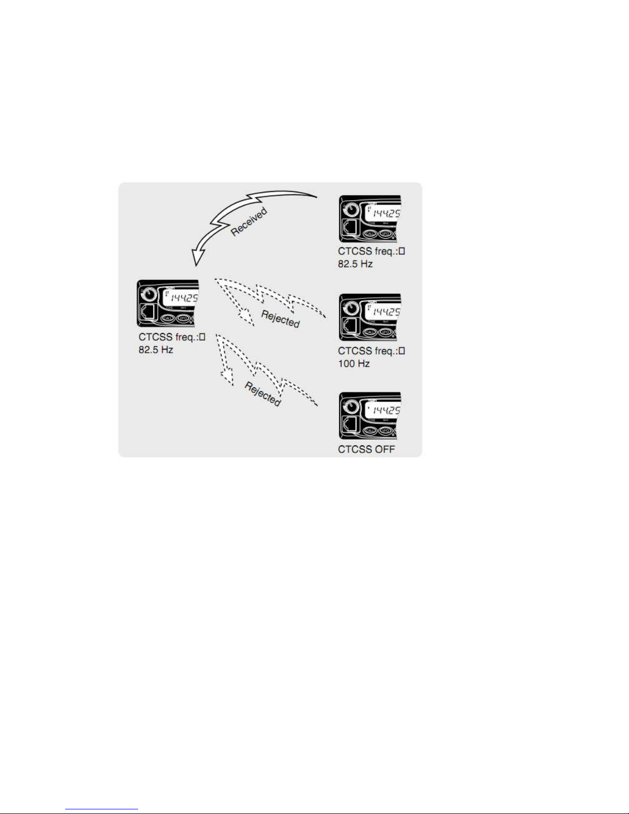
SELECTIVE CALL
CTCSS AND DCS
You may sometimes want to hear calls from only specific persons or groups. In this case, use
Selective Call. This transceiver is equipped with CTCSS (Continuous Tone Coded Squelch
System) and DCS (Digital Coded Squelch). These Selective Calls allow you to ignore (not hear)
unwanted calls from other persons who are using the same frequency. The transceiver unmutes
only when it receives a signal having the same CTCSS tone or DCS code.
Note: CTCSS and DCS do not cause your conversation to be private or scrambled. It only relieves
you from listening to unwanted conversations.
CTCSS
A CTCSS tone is a sub-audible tone and is selectable from among the 42 tone frequencies listed in
the table on page 43. The list includes 37 EIA standard tones and 5 non-standard tones.
To activate CTCSS, press [F], [CALL].
•As you press [F], [CALL], the selection steps as below:
“OFF” ➞ “TONE” ➞ “CTCSS” ➞ “DCS” ➞ “OFF”.
•“CT” appears on the upper part of display, indicating that the CTCSS function is activated.
When CTCSS is ON, you will hear calls only when the selected CTCSS tone is received. To
answer the call, press and hold MIC [PTT], then speak into the Microphone.
Note:
You cannot use the CTCSS and Tone/ DCS functions simultaneously. Switching the CTCSS
function ON after having activated the Tone/ DCS functions deactivates the Tone/ DCS
functions.
If you select a high CTCSS frequency, receiving audio or noise that contains the same frequency
Page 50
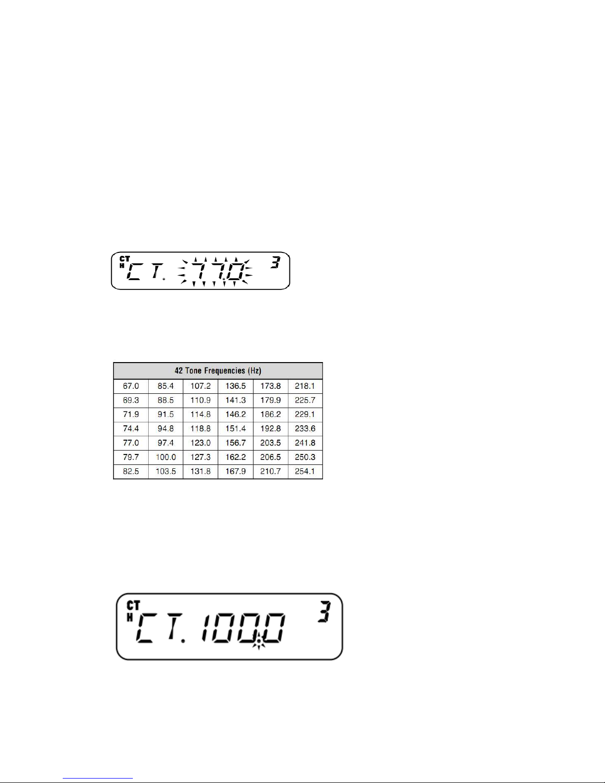
portions may cause CTCSS to function incorrectly. To prevent noise from causing this problem,
select an appropriate squelch level {page 14}.
While transmitting the 1750 Hz tone by pressing [CALL] {page 25}, the transceiver does not
transmit the CTCSS tone.
SELECTING A CTCSS FREQUENCY
1 Press [F], [MENU] and turn the Tuning control or press MIC [UP]/[DWN] to select Menu No. 3
(CT).
The current CTCSS frequency appears.
2 Press [MENU] and turn the Tuning control to select your desired CTCSS frequency.
The selectable CTCSS frequencies are the same as those for the Tone frequency. Refer to the table
below for the available CTCSS frequencies.
3 Press [MENU] to store the new setting or any other key to cancel.
4 Press any key other than [MENU] to exit Menu Mode.
Note: To use the selected CTCSS tone, you must first turn the CTCSS function ON.
AVAILABLE CTCSS TONE FREQUENCIES
CTCSS FREQUENCY ID SCAN
This function scans through all CTCSS frequencies to identify the incoming CTCSS frequency on
the received signal. You may find this useful when you cannot recall the CTCSS frequency that
the other persons in your group are using.
1 Press [F], [MENU] and turn the Tuning control to select Menu No. 3 (CT).
2 Press [MENU] (1s) to start the CTCSS Frequency ID Scan.
•While scanning, the decimal point of the CTCSS frequency blinks.
•To reverse the scan direction, turn the Tuning control or press MIC [UP]/[DWN].
Page 51

•To quit the function, press any key.
•When a CTCSS frequency is identified, the identified frequency appears and blinks.
3 Press [MENU] to program the identified frequency in place of the current CTCSS frequency or
press any other key to exit the CTCSS Frequency ID Scan.
Turn the Tuning control or press MIC [UP]/[DWN] while the identified frequency is blinking to
resume scanning.
4 Press any key other than [MENU] to exit Menu Mode.
Note:
CTCSS turns ON automatically when performing CTCSS Frequency ID Scan, even if the current
frequency is not set with CTCSS.
Received signals are monitored through the speaker while scanning is in progress.
The transceiver continues to check the Weather Alert Channel and Priority Channel during CTCSS
scanning.
CTCSS Frequency ID Scan does not scan the tone if a signal is not detected.
DCS
DCS is similar to CTCSS. However, instead of using an analog audio tone, it uses a continuous
sub-audible digital waveform represented by a 3-digit octal number.
You can select a DCS code from among the 104 DCS codes listed in the table below.
To activate DCS, press [F], [CALL].
•As you press [F], [CALL], the selection steps as follows:
“OFF” ➞ “TONE” ➞ “CTCSS” ➞ “DCS” ➞ “OFF”.
•“DCS” appears on the upper part of display, indicating that the DCS function is activated.
When DCS is ON, you will hear calls only when the selected DCS code is received. To answer the
call, press and hold MIC [PTT], then speak into the Microphone.
Note: You cannot use the DCS function and CTCSS/ Tone functions simultaneously. Switching the
DCS function ON after having activated the CTCSS/ Tone functions deactivates the CTCSS/ Tone
functions.
SELECTING A DCS CODE
1 Press [F], [MENU] and turn the Tuning control to select Menu No. 4 (DCS).
The current DCS code appears.
2 Press [MENU] and turn the Tuning control to select your desired DCS code.
The current DCS code appears and blinks.
Page 52
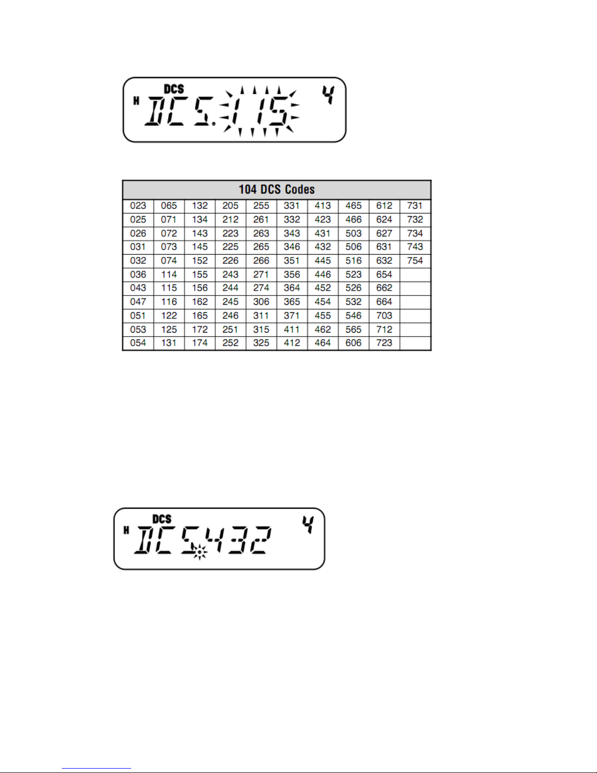
The available DCS codes are shown in the following table.
3 Press [MENU] to store the new code or any other key to cancel.
4 Press any key other than [MENU] to exit Menu Mode.
DCS CODE ID SCAN
This function scans through all DCS codes to identify the incoming DCS code on the received
signal. You may find this useful when you cannot recall the DCS code that the other persons in
your group are using.
1 Press [F], [MENU] and turn the Tuning control to select Menu No. 4 (DCS).
2 Press [MENU] (1s) to start the DCS Code ID Scan function.
•While scanning, the decimal point between “DCS” and the DCS code blinks.
•To quit the function, press any key.
•When a DCS code is identified, the identified DCS code appears and blinks.
Page 53
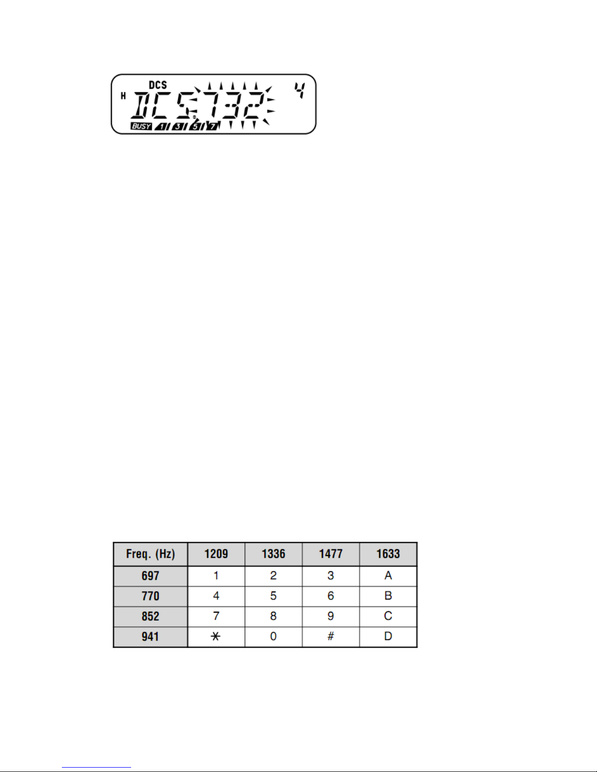
3 Press [MENU] to program the identified DCS code in place of the current DCS code or press
any other key to exit the DCS Code ID Scan.
•Turn the Tuning control or press MIC [UP]/[DWN] while the identified DCS code is blinking to
resume scanning.
4 Press any key other than [MENU] to exit Menu Mode.
Note:
DCS turns ON automatically when performing DCS Code ID Scan, even if the current frequency
is not set with DCS.
Received signals are monitored through the speaker while scanning is in progress.
The transceiver continues to check the Weather Alert Channel and Priority Channel during DCS
scanning.
DCS Code ID Scan does not scan the code if a signal is not detected.
DUAL TONE MULTI-FREQUENCY (DTMF) FUNCTIONS
This transceiver provides you with 10 dedicated DTMF Memory Channels. You can store a DTMF
number (16 digits max) in each of these channels to recall later for speed dialing.
Many repeaters in the U.S.A. and Canada offer a service called Autopatch. You can access the
public telephone network via such a repeater by sending DTMF tones. For further information,
consult your local repeater reference.
MANUAL DIALING
The keys on the MIC keypad function as DTMF keys; the 12 keys found on a push-button
telephone plus 4 additional keys (A, B, C, D).
To perform Manual Dialing, follow the steps below.
1 Press and hold MIC [PTT] to transmit.
2 While transmitting, press the keys in sequence on the keypad, to send the DTMF tones.
• The corresponding DTMF tones are transmitted.
•When DTMF TX Hold is activated {page 51}, you do not need to continuously press MIC [PTT]
to remain in transmission mode. However, transmission mode is retained for only 2 seconds after
Page 54
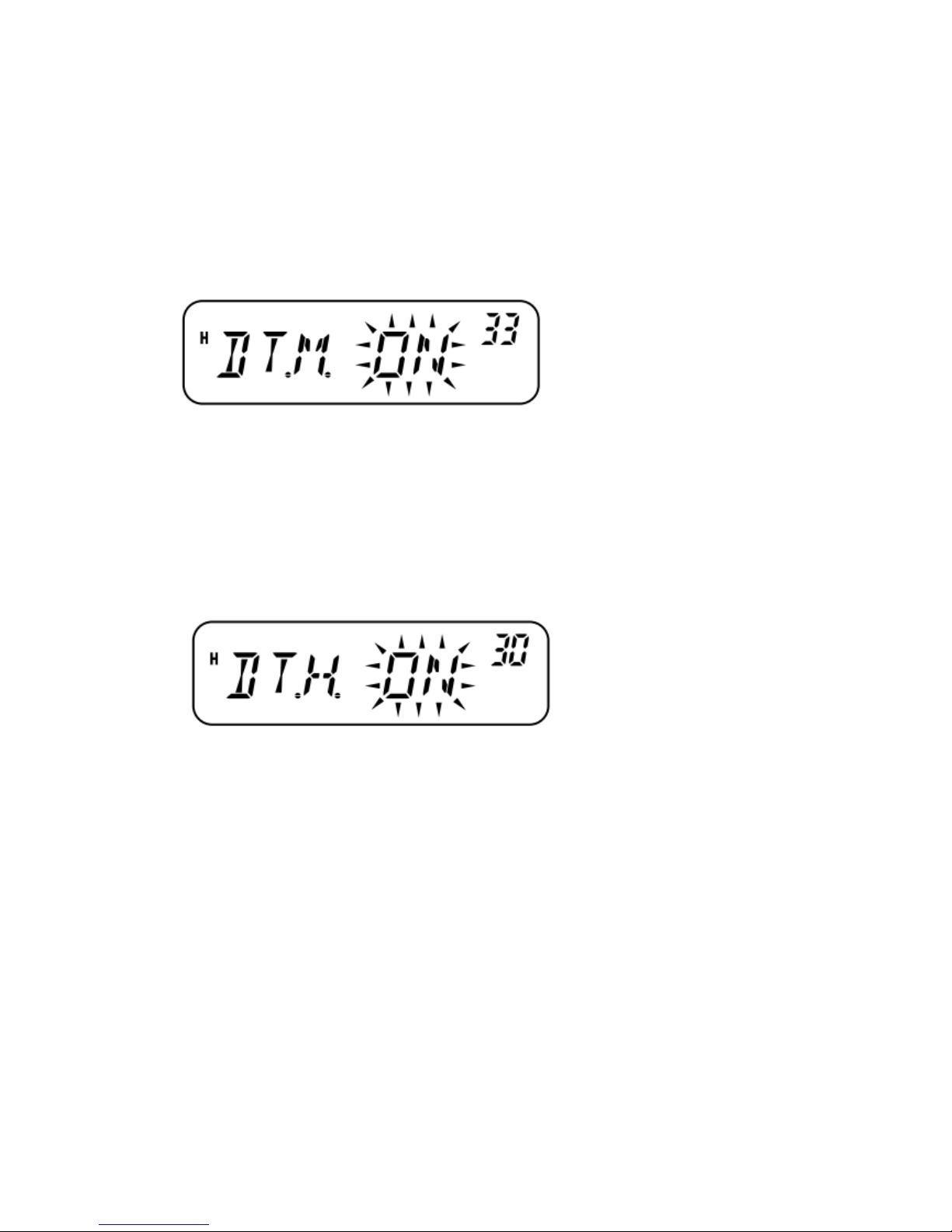
pressing a key, so if the next key is not pressed within this time limit, the transceiver stops
transmitting.
DTMF MONITOR
When pressing the MIC DTMF keys, you will not hear DTMF tones emitted from the speaker.
However, you can monitor the DTMF tones if desired.
1 Press [F], [MENU] and turn the Tuning control to select Menu No. 33 (DT.M).
2 Press [MENU] and turn the Tuning control to select“ON” or “OFF” (default).
3 Press [MENU] to store the setting or any other key to cancel.
4 Press any key other than [MENU] to exit Menu Mode.
DTMF TX HOLD
This function causes the transceiver to remain in transmission mode for 2 seconds after you
release each key. So, you can release MIC [PTT] while sending DTMF tones.
1 Press [F], [MENU] and turn the Tuning control to select Menu No. 30 (DT.H).
2 Press [MENU] and turn the Tuning control to select“ON” or “OFF” (default).
3 Press [MENU] to store the setting or any other key to cancel.
4 Press any key other than [MENU] to exit Menu Mode.
AUTOMATIC DIALER
If you use the 10 dedicated DTMF Memory Channels to store DTMF numbers, you do not need to
remember a long string of digits.
STORING A DTMF NUMBER IN MEMORY
1 Press [F], [MENU] and turn the Tuning control to select Menu No. 28 (DTMF.MR).
2 Press [MENU] and turn the Tuning control to select your desired DTMF Memory Channel
number from 0 to 9.
You can also select a DTMF Memory Channel by using MIC [UP]/[DWN].
Page 55
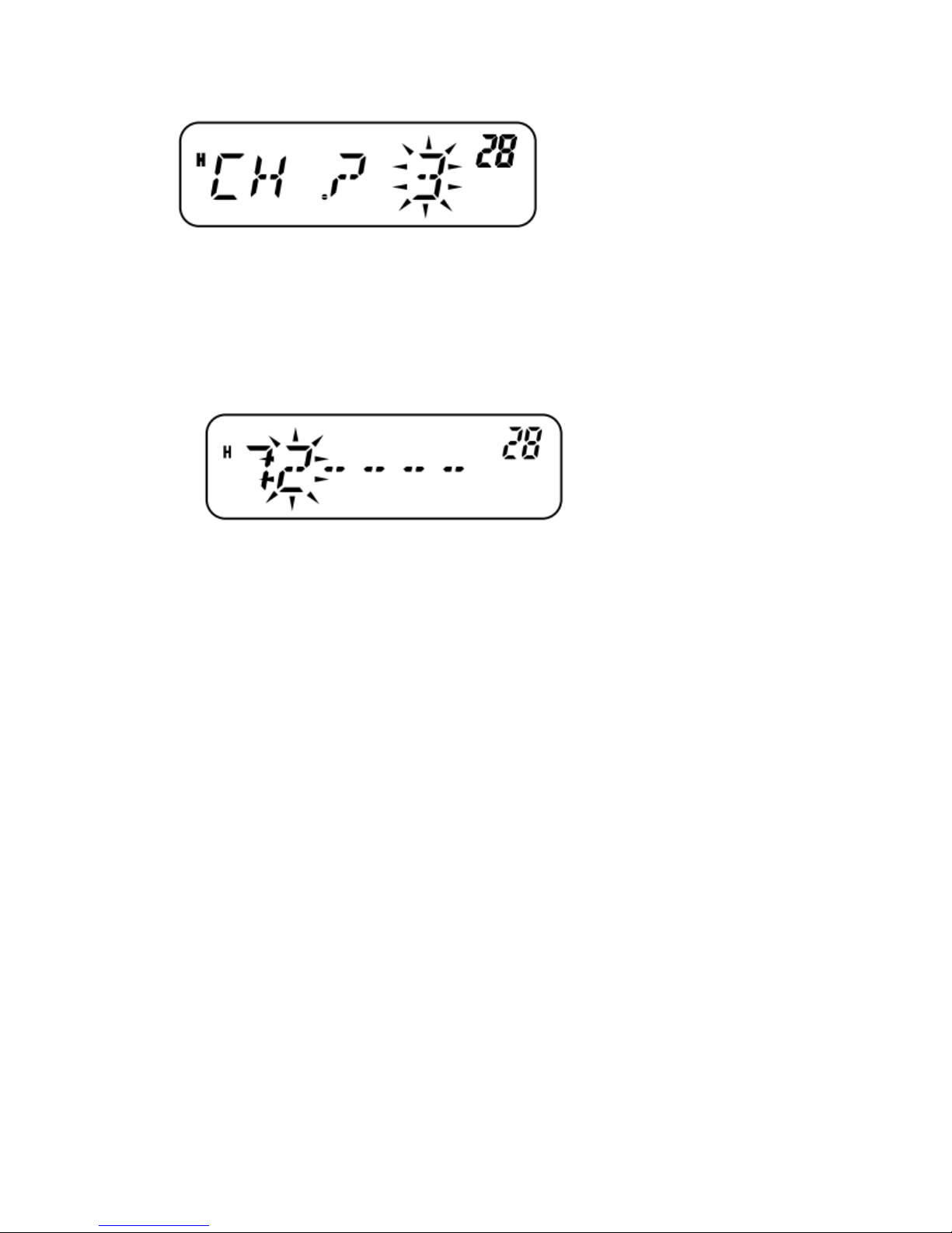
3 Press [MENU].
The DTMF code entry display appears and the first digit blinks.
4 Turn the Tuning control to select a DTMF code.
•You can also enter a DTMF code using the MIC keypad. Simply press your desired DTMF codes
on the keypad.
•On the display,* is represented by “E” and # is represented by “F”.
5 Press [MR] to select the DTMF code and move the cursor to the next digit.
To move to the previous digit, press [VFO]. To delete the character at the current cursor position,
press [F].
6 Repeat steps 4 and 5 to enter up to 16 digits.
7 Press [MENU] to complete the entry.
•Press any key other than [MR], [VFO], [F], and [MENU] to cancel the entry.
•To complete an entry of less than 16 digits, press [MENU] two times.
8 Press any key other than [MENU] to exit Menu Mode.
CONFIRMING STORED DTMF NUMBERS
1 Press [F], [MENU] and turn the Tuning control to select Menu No. 28 (DTMF.MR).
2 Press [MENU] and turn the Tuning control to select your desired DTMF Memory Channel
number from 0 to 9.
You can also select a DTMF Memory Channel by using MIC [UP]/[DWN].
3 Press [REV].
The numbers scroll across the display and the DTMF tones emit from the speaker without
transmitting.
4 Press any key other than [REV] or [MENU] to exit.
TRANSMITTING A STORED DTMF NUMBER
1 Press MIC [PTT]+ MIC [PF/D].
2 Release MIC [PF/D] (continue pressing MIC [PTT]), then press a key from 0 to 9 to transmit the
desired DTMF Memory Channel number.
•To transmit tone “D”, press MIC [PF/D] again.
•The number stored in the channel scrolls across the display, accompanied by DTMF tones from
the speaker. (DTMF tones are not emitted if Menu No. 33 (DT.M) is set to “OFF”.)
Page 56
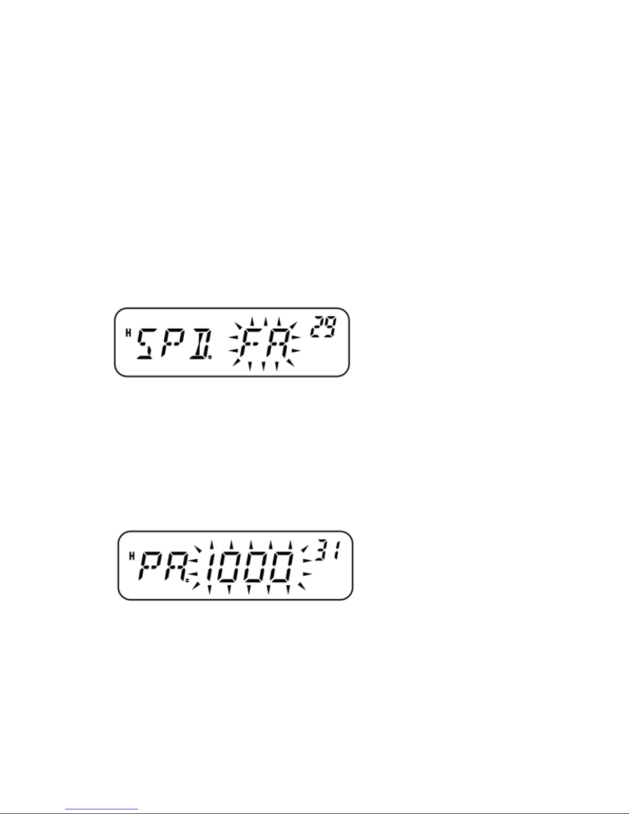
•After transmission, the frequency display is restored.
3 Release MIC [PTT].
Note:
If you select an empty DTMF Memory Channel and press [MENU], the frequency display is
restored.
In step 2, above, you can preview the DTMF Memory Channels first by turning the Tuning control
or pressing MIC [UP]/[DWN].
ADJUSTING THE DTMF TONE TRANSMISSION SPEED
This transceiver allows you to configure the DTMF number transmission speed between Fast
(default) and Slow. If a repeater cannot respond to the fast speed, adjust this parameter.
1 Press [F], [MENU] and turn the Tuning control to select Menu No. 29 (SPD).
2 Press [MENU] and turn the Tuning control to select“FA” (Fast) or “SL” (Slow).
The tone duration of Fast is 50 ms and Slow is 100 ms.
3 Press [MENU] to store the setting or any other key to cancel.
4 Press any key other than [MENU] to exit Menu Mode.
ADJUSTING THE PAUSE DURATION
You can change the pause duration (a space digit) stored in Memory Channels. The default setting
is 500 milliseconds.
1 Press [F], [MENU] and turn the Tuning control to select Menu No. 31 (PA).
2 Press [MENU] and turn the Tuning control to select 100, 250, 500 (default), 750, 1000, 1500, or
2000 ms.
3 Press [MENU] to store the setting or any other key to cancel.
4 Press any key other than [MENU] to exit Menu Mode.
DTMF LOCK
You sometimes may want to disable the keypad to avoid accidental DTMF transmission. In this
case, turn the DTMF Lock function ON.
1 Press [F], [MENU] and turn the Tuning control to select Menu No. 32 (DT.L).
2 Press [MENU] and turn the Tuning control to select“ON” or “OFF” (default).
Page 57
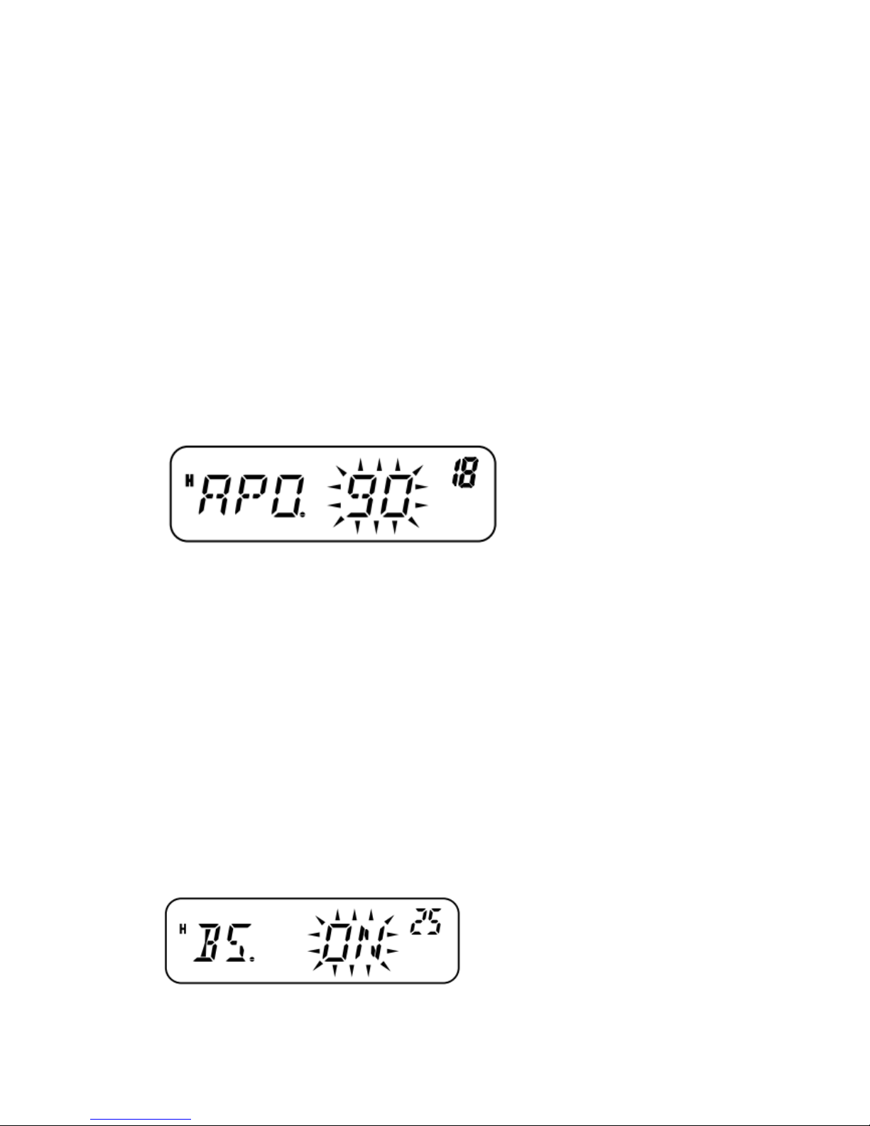
3 Press [MENU] to store the setting or any other key to cancel.
4 Press any key other than [MENU] to exit Menu Mode. When this function is activated, you
cannot send DTMF tones using the MIC keypad. DTMF memory transmission is also inhibited.
AUXILIARY FUNCTIONS
APO (AUTO POWER OFF)
The transceiver switches OFF automatically if no keys or controls are pressed or adjusted for the
selected duration. One minute before the transceiver switches OFF, warning beeps sound for a few
seconds and “APO” blinks.
You can select the APO time from OFF (disable), 30, 60, 90, 120, or 180 minutes.
1 Press [F], [MENU] and turn the Tuning control to select Menu No. 18 (APO).
2 Press [MENU] and turn the Tuning control to select the APO time from OFF (default), 30, 60,
90, 120, or 180 minutes.
3 Press [MENU] to store the setting or any other key to cancel.
4 Press any key other than [MENU] to exit Menu Mode.
Note:
APO continues to count even while the transceiver is scanning.
The APO timer starts counting down the time when no key presses, no control adjustments, and no
PC control command sequences are detected.
The APO warning beep sounds even if Menu No. 24 (BP) {page 52} is set to “OFF” or the
volume level is 0.
BEAT SHIFT
Since the transceiver uses a MICroprocessor to control various functions of the transceiver, the
CPU clock oscillator’s harmonics or image may appear on some spots of the reception frequencies.
In this case, turn the Beat Shift function ON.
1 Press [F], [MENU] and turn the Tuning control to select Menu No. 25 (BS).
2 Press [MENU] and turn the Tuning control to select“ON” or “OFF” (default).
3 Press [MENU] to store the setting or any other key to cancel.
Page 58
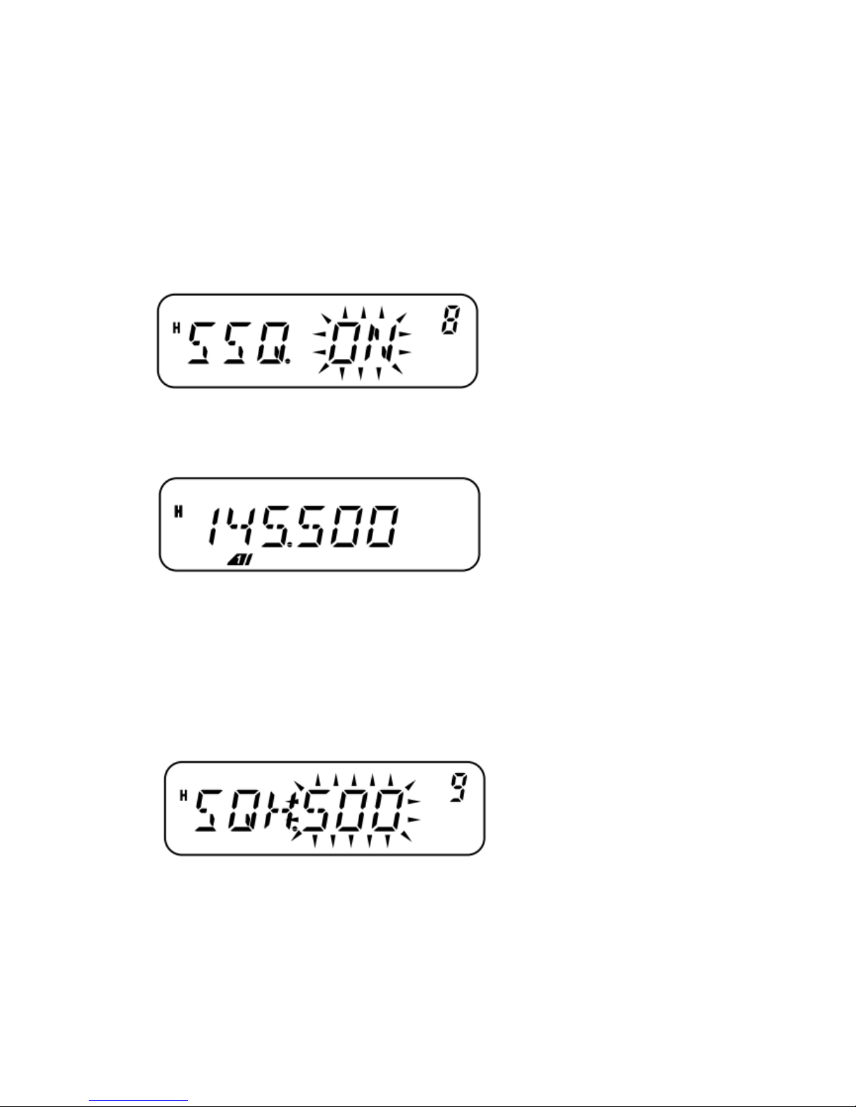
4 Press any key other than [MENU] to exit Menu Mode.
S-METER SQUELCH
S-meter Squelch causes the squelch to open only when a signal with a strength greater than or the
same as the S-meter setting is received. This function relieves you from constantly resetting the
squelch when receiving weak stations you have no interest in.
1 Press [F], [MENU] and turn the Tuning control to select Menu No. 8 (SSQ).
2 Press [MENU] and turn the Tuning control to select“ON” or “OFF” (default).
3 Press [MENU] to store the setting.
The S-meter setting segments appear.
4 Press any key other than [MENU] to exit Menu Mode.
5 Press [F], [REV] to enter S-Meter Level Select Mode.
6 Turn the Tuning control to select your desired level.
7 Press any key other than [ ] (Power) to store the setting and exit S-Meter Level Select Mode.
SQUELCH HANG TIME
When using S-meter Squelch, you may want to adjust the time interval between when the received
signals drop and when the squelch closes.
1 Press [F], [MENU] and turn the Tuning control to select Menu No. 9 (SQH).
2 Press [MENU] and turn the Tuning control to select from OFF (default), 125, 250, and 500 ms.
3 Press [MENU] to store the setting or any other key to cancel.
4 Press any key other than [MENU] to exit Menu Mode.
Page 59
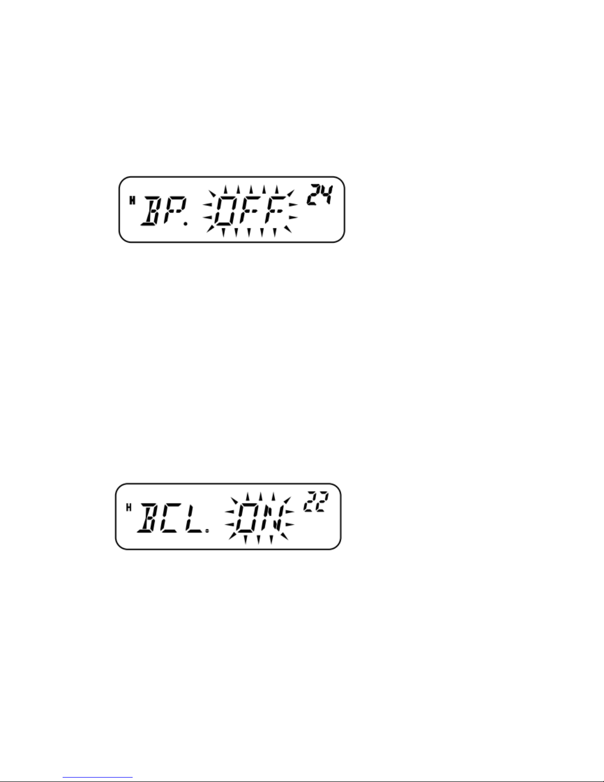
BEEP FUNCTION
The Beep function provides confirmation of entry, error status, and malfunctions of the transceiver.
We recommend you leave this function ON in order to detect erroneous operations and
malfunctions.
However, to turn the beep function OFF:
1 Press [F], [MENU] and turn the Tuning control to select Menu No. 24 (BP).
2 Press [MENU] and turn the Tuning control to select“OFF”.
3 Press [MENU] to store the setting or any other key to cancel.
4 Press any key other than [MENU] to exit Menu Mode.
The transceiver generates the following warning beeps even if the Beep function is turned OFF.
•APO warning beeps {page 51}
•Weather Alert beep {page 35}
•Time-out Timer warning beep {page 57}
Note: The beep output level is linked to the VOL control position.
BUSY CHANNEL LOCKOUT
This function is used to prevent transmitting on a channel or frequency that somebody else is
currently using. When turned ON, an error beep sounds and you cannot transmit even if you press
MIC [PTT] while another party is using the channel or frequency.
1 Press [F], [MENU] and turn the Tuning control to select Menu No. 22 (BCL).
2 Press [MENU] and turn the Tuning control to select“ON” or “OFF” (default).
3 Press [MENU] to store the setting or any other key to cancel.
4 Press any key other than [MENU] to exit Menu Mode.
FREQUENCY STEP SIZE
Choosing the correct frequency step size is essential in selecting your exact receive frequency
using the Tuning control or MIC [UP]/[DWN]. You can select your desired frequency step size
from: 2.5 kHz, 5 kHz, 6.25 kHz, 10 kHz, 12.5 kHz, 15 kHz, 20 kHz, 25 kHz, 30 kHz, 50 kHz, 100
kHz.
To change the frequency step size:
Page 60
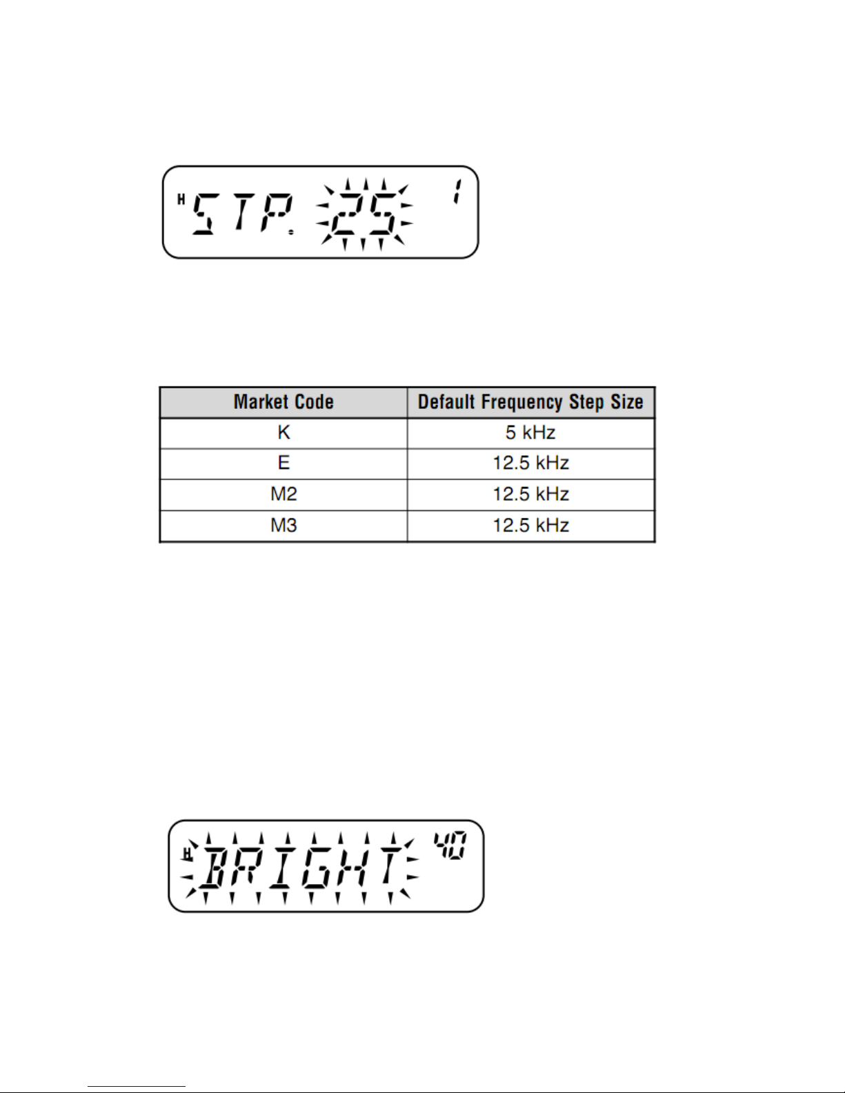
1 While in VFO Mode, press [F], [MENU] and turn the Tuning control to select Menu No. 1
(STP).
2 Press [MENU] and turn the Tuning control to select your desired frequency step size.
3 Press [MENU] to store the setting or any other key to cancel.
4 Press any key other than [MENU] to exit Menu Mode.
Note: If you change to a frequency step size that does not match the current operating frequency,
the transceiver automatically adjusts the frequency to match the new frequency step size.
The default step size for each model is as follows:
Note: The market code is printed on the barcode label of the carton box.
DISPLAY BACKLIGHT
You can manually change the display brightness to match the lighting conditions where you are
operating the transceiver. This setting can be permanent or the display can light up only when keys
are pressed.
PERMANENT BACKLIGHT
When a permanent setting is selected, the backlight will remain at that setting until it is changed
again. The default setting is the maximum brightness.
1 Press [F], [MENU] and turn the Tuning control to select Menu No. 40 (BRIGHT).
2 Press [MENU] and turn the Tuning control to adjust the display brightness.
3 Press [MENU] to store the setting or any other key to cancel.
4 Press any key other than [MENU] to exit Menu Mode.
Note: Setting the brightness to OFF (minimum level 1) will turn the front panel key backlight
Page 61
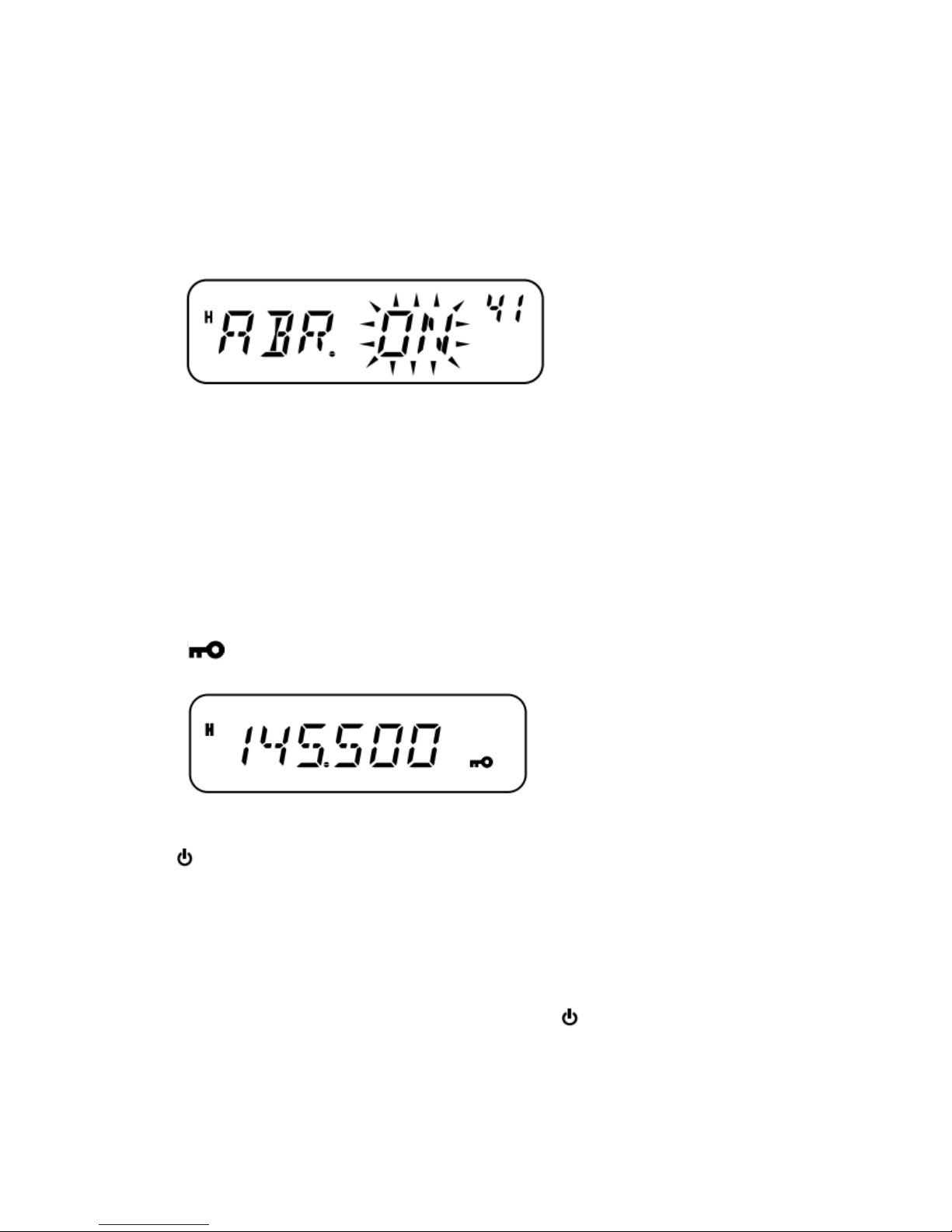
OFF.
AUTOMATIC BACKLIGHT
When using automatic backlight, the display backlight will illuminate every time a front panel or
Microphone key is pressed. The backlight remains on for 5 seconds before it turns off again.
1 Press [F], [MENU] and turn the Tuning control to select Menu No. 41 (ABR).
2 Press [MENU] and turn the Tuning control to select“ON” or “OFF” (default).
3 Press [MENU] to store the setting or any other key to cancel.
4 Press any key other than [MENU] to exit Menu Mode.
Note: No change occurs if the brightness is set to the highest level.
LOCK FUNCTION
The lock function disables most of the keys to prevent you from accidentally activating a function.
Transceiver Lock is suitable for a typical mobile installation where you select most operations
using the Microphone.
1 Press [F] (1s).
•“ ” appears when this function is ON.
• The following keys cannot be locked:
[ ] (Power), [F] (1s), [F]+[REV], Volume control, [PTT], and the MIC keypad.
2 Press [F] (1s) again to unlock the keys.
Note:
The Tuning control is also locked. To retain use of the Tuning control while the Lock function is
ON, access Menu No. 27 (ENC) {below} and select “ON”.
You cannot reset the transceiver {page 67} while the Lock function is ON.
You cannot switch the transceiver operating mode by pressing [ ] (Power) + any key.
Microphone PF keys {page 55} operate normally even if the Lock function is ON.
Page 62
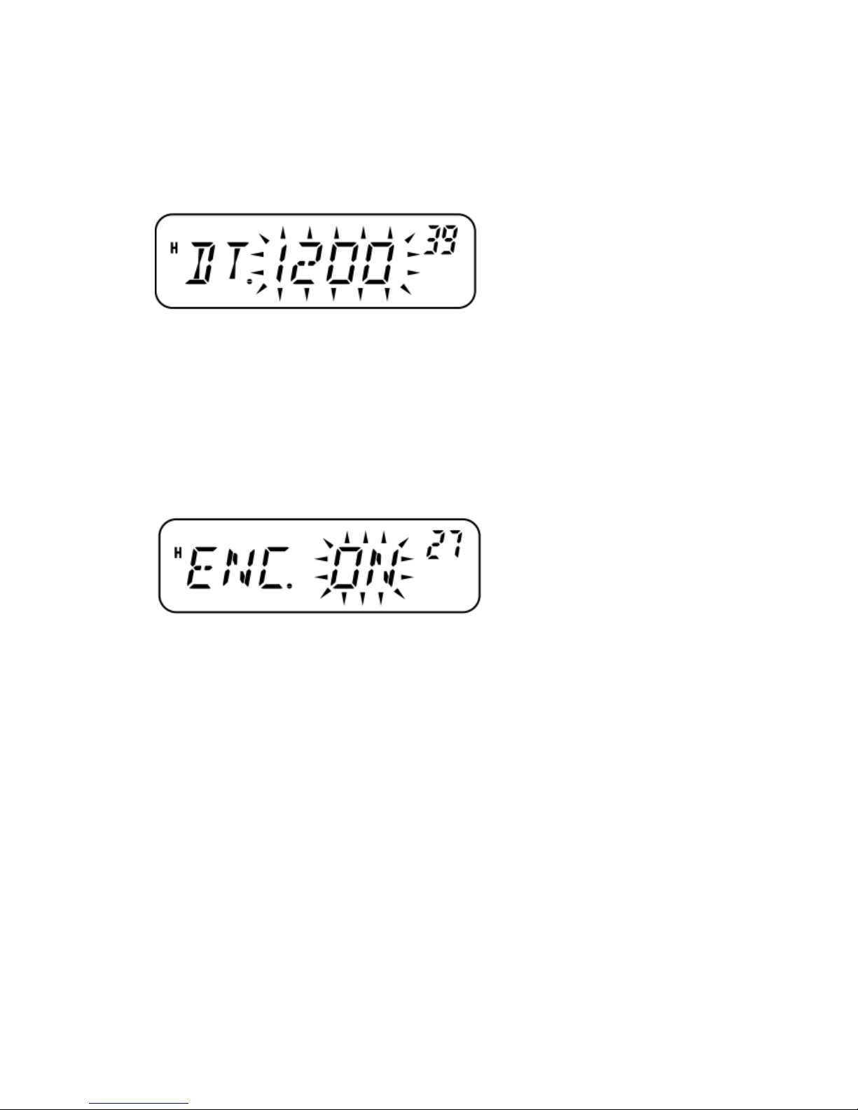
DATA COMMUNICATION SPEED
When the transceiver is connected to a TNC {page 7} (E market models only), you can adjust the
communication speed between 1200 bps and 9600 bps.
1 Press [F], [MENU] and turn the Tuning control to select Menu No. 39 (DT).
2 Press [MENU] and turn the Tuning control to select “1200” (default) or “9600”.
3 Press [MENU] to store the setting or any other key to cancel.
4 Press any key other than [MENU] to exit Menu Mode.
TUNE ENABLE
While the Lock function is ON, you sometimes may want to turn the Tuning control to change the
frequency. In this case, turn the Tune Enable function ON.
1 Press [F], [MENU] and turn the Tuning control to select Menu No. 27 (ENC).
2 Press [MENU] and turn the Tuning control to select“OFF” (default) or “ON”.
3 Press [MENU] to store the setting or any other key to cancel.
4 Press any key other than [MENU] to exit Menu Mode.
MICROPHONE PF KEYS (KEYPAD MODELS ONLY)
You can access many transceiver settings without using transceiver keys or controls.
Microphone keys PF/D, MR/C, VFO/B, and CALL/A are programmable with different transceiver
functions.
The Microphone key default assignments are as follows:
MIC PF1 key [PF/D]:1 MHz step
MIC PF2 key [MR/C]: Memory Recall
MIC PF3 key [VFO/B]: VFO Select
MIC PF4 key [CALL/A]: Call Channel Select
Note:
Turn the transceiver OFF before connecting the Microphone.
Menu No. 34 (MCL) must be configured to“OFF”in order to program the Microphone keys.
1 Press [F], [MENU] and turn the Tuning control to select one of Menu No. 35 to Menu No. 38
(PF1 ~ PF4).
Page 63

2 Press [MENU] and turn the Tuning control to select the programmable function from the list
provided below.
59
3 Press [MENU] to store the setting or any other key to
cancel.
4 Press any key other than [MENU] to exit Menu Mode.
PROGRAMMABLE FUNCTIONS
•MONI: Monitor function ON/OFF
•ENTER: Used to enter a frequency or memory channel number with the keypad
•1750: Transmit 1750 Hz
•VFO: Enter VFO Mode
•MR: Enter MR Mode
•CALL: Select the Call Channel
•MHZ: Enter 1 MHz Step Mode
•REV: Reverse function ON/OFF (momentary press) and Auto Simplex Checker function
ON/OFF (must be held down for 1 second to activate)
•SQL: Enter Squelch Mode
•M--V: Memory to VFO transfer
•M.IN: Store a Memory Channel
•C.IN: Store the Call Channel
•MENU: Enter Menu Mode
•SHIFT: Shift function ON/OFF
•LOW: Select transmission power
•BRIGHT: Adjust display backlight
•LOCK: Transceiver Lock function ON/OFF (must be held down for 1 second to activate)
•TONE: Selection for Tone/ Selective Call
•STEP: Select the frequency step size
Note: Rather than entering Menu Mode and selecting PF1 ~ PF4, you can simply press and hold
the PF key you want to program, then turn the transceiver power ON. When programming the PF
keys in this manner, select the function by turning the Tuning control or pressing MIC
[UP]/[DWN], press [MENU] to store the setting, then press any key other than [MENU] to exit
Menu Mode.
NARROW BAND FM OPERATION
By default, the transceiver operates in normal FM (±5 kHz) mode for both transmission and
reception. You can also operate the transceiver in narrow band FM (±2.5 kHz).
Page 64
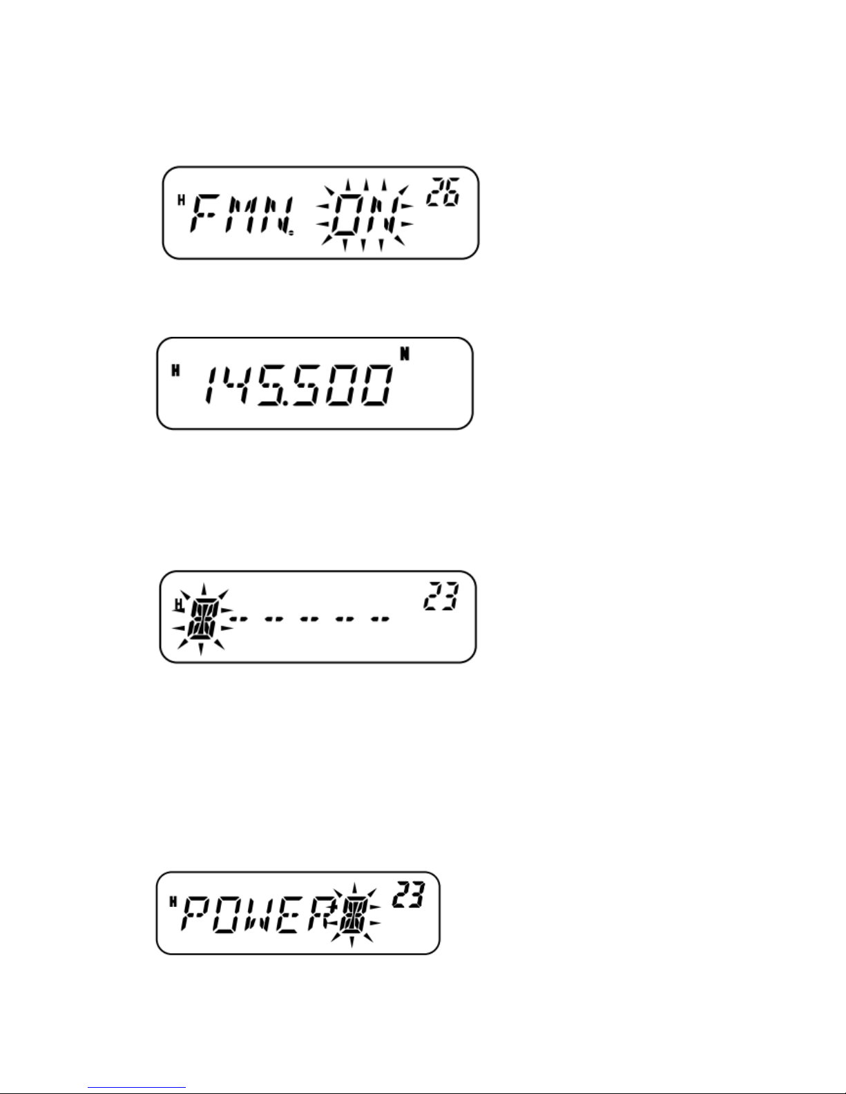
To operate the transceiver in narrow band FM:
1 Press [F], [MENU] and turn the Tuning control to select Menu No. 26 (FMN).
2 Press [MENU] and turn the Tuning control to select“ON” or “OFF” (default).
3 Press [MENU] to store the setting or any other key to cancel.
4 Press any key other than [MENU] to exit Menu Mode. When narrow band FM operation is ON,
“N” appears in the top right of the LCD.
Note: You can store the narrow band FM operation status to the Memory Channels {page 29}.
POWER-ON MESSAGE
You can change the Power-on message ( up to 6 characters) when the transceiver is turned ON.
1 Press [F], [MENU] and turn the Tuning control to select Menu No. 23 (P.ON.MSG).
2 Press [MENU].
The current message and entry cursor appear.
3 Turn the Tuning control to select a character.
•You can enter the following alphanumeric characters: 0 ~ 9, A ~ Z, – (hyphen), / (slash), and
space.
•Rather than using the Tuning control, you can use the MIC keypad (keypad models only) to enter
alphanumeric characters {page 59}.
4 Press [MR] to move to the next digit.
•To move to the previous digit, press [VFO]. To delete the character at the current cursor position,
press [F].
5 Repeat steps 3 and 4 to enter up to 6 digits.
6 Press [MENU] to complete the setting and store the Power-on message.
Page 65
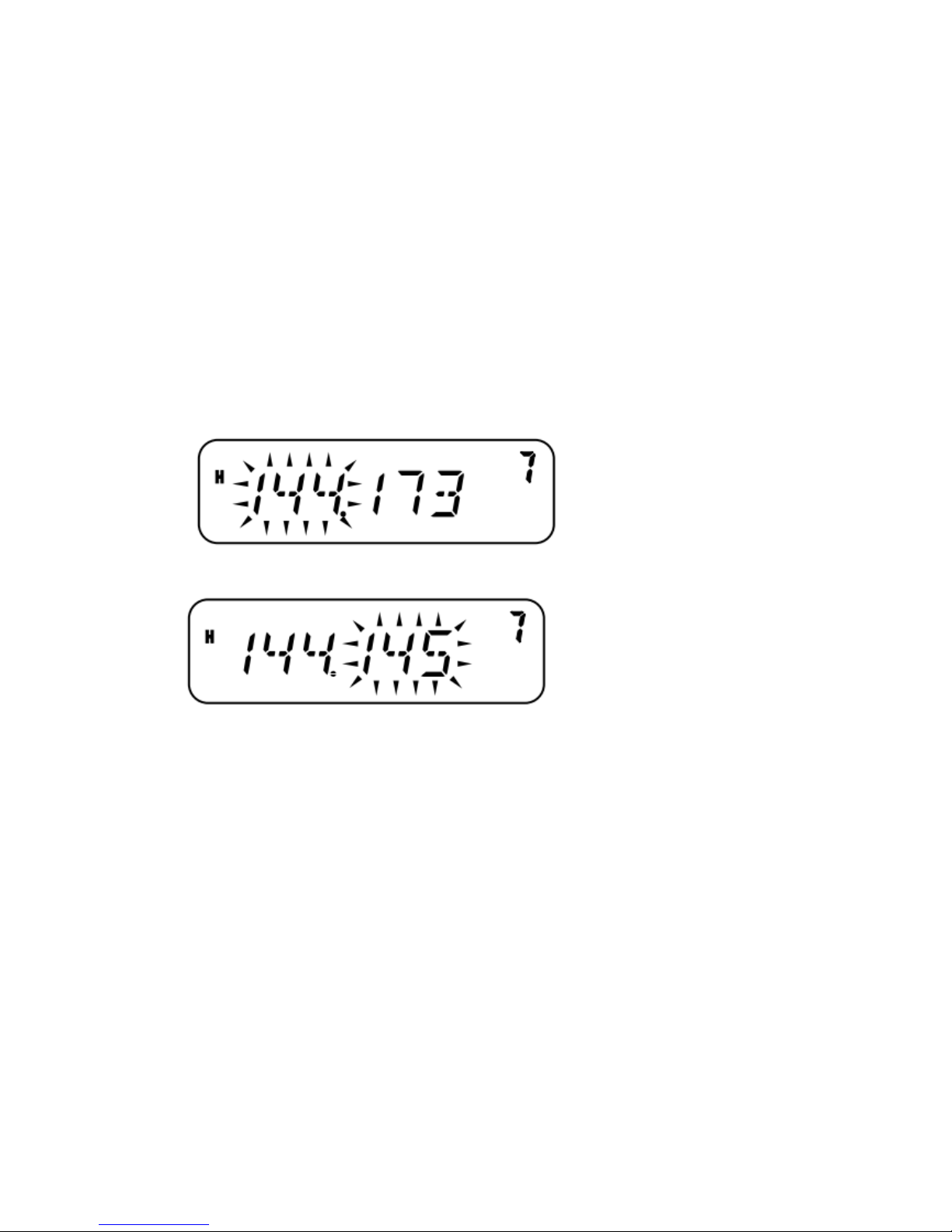
7 Press any key other than [MENU] to exit Menu Mode.
Note: If a Power-on message is not set, the transceiver model name appears when the transceiver
power is turned ON.
PROGRAMMABLE VFO
To limit the operating frequencies within a certain range, program the upper and lower frequency
limits to the program VFO parameters. For example, if you select 144 MHz for the lower limit and
145 MHz for the upper limit, the tunable range will be limited from 144.000 MHz to 145.9975
MHz.
1 While in VFO mode, press [F], [MENU] and turn the Tuning control to select Menu No. 7
(P.VFO).
The current programmable frequency range for the band appears.
2 Press [MENU] and turn the Tuning control to select the lower limit frequency (in MHz).
3 Press [MENU] and turn the Tuning control to select the upper limit frequency (in MHz).
4 Press [MENU] to store the setting or any other key to cancel.
5 Press any key other than [MENU] to exit Menu Mode.
Note:
You cannot program the 100 kHz or lower digits.
The upper limit frequency cannot be set lower than the selected lower limit frequency.
TIME-OUT TIMER
The Time-out Timer limits the time of each transmission to a maximum of 3, 5, or 10 (default)
minutes. Just before the transceiver stops the transmission, a warning beep sounds. This function
is necessary to protect the transceiver from thermal damage and can therefore not be turned OFF.
1 Press [F], [MENU] and turn the Tuning control to select Menu No. 21 (TOT).
2 Press [MENU] and turn the Tuning control to select“3”, “5” or “10” (default) minutes.
Page 66
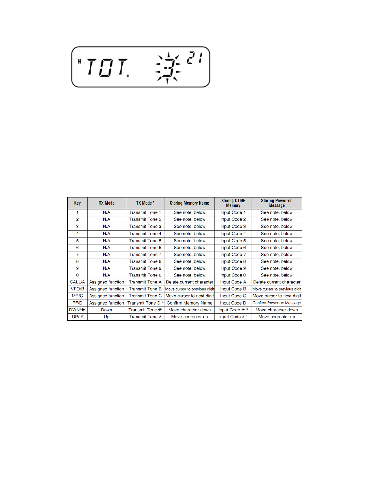
3 Press [MENU] to store the setting or any other key to cancel.
4 Press any key other than [MENU] to exit Menu Mode.
Note: A warning beep sounds even if you set Menu No. 24 (BP) to OFF {page 52}
MICROPHONE CONTROL
You can change numerous transceiver settings by operating the MIC DTMF keys.
The following table shows what function is switched ON and OFF or which setting is changed by
pressing the DTMF keys in the appropriate mode of operation.
1 DTMF tones are not transmitted in Tx Mode if the DTMF Lock function is ON.
2 When transmitting a stored DTMF number, press MIC [PTT] + MIC [PF/D], release MIC
[PF/D], then press a Memory Channel number from 0 to 9. To transmit the“D” tone, press MIC
[PF/D] again.
3 On the display, * is represented by “E”.
4 On the display, # is represented by “F”.
Note: When storing a Memory Name or Power-on message, the DTMF keys can be used. Each
time a key is pressed, the displayed character will change, according to the table below.
Page 67
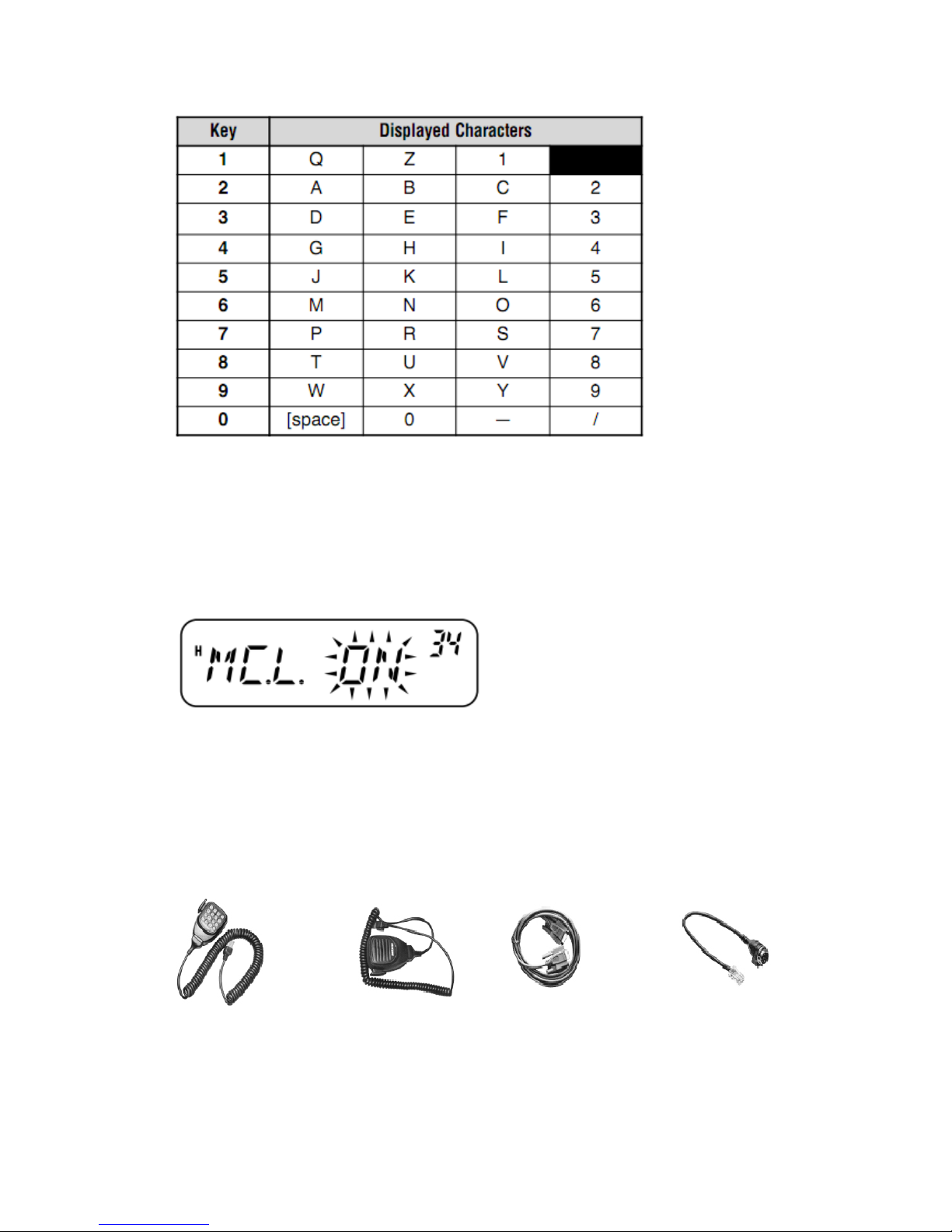
MIC LOCK
The MIC Lock function disables the MIC PF keys to prevent you from accidentally changing the
transceiver operation.
1 Press [F], [MENU] and turn the Tuning control to select Menu No. 34 (MC.L).
2 Press [MENU] and turn the Tuning control to select“ON” or “OFF” (default).
3 Press [MENU] to store the setting or any other key to cancel.
4 Press any key other than [MENU] to exit Menu Mode.
Note: The MIC Lock function will not lock the DTMF keys.
OPTIONAL ACCESSORIES
DTMF Microphone Microphone Programming Cable Modular to 8-pin
Microphone Plug
Although the key names differ from those on the supplied DTMF Microphone, the key functions
are the same.
Page 68

TROUBLE SHOOTING
MAINTENANCE
GENERAL INFORMATION
This product has been factory modulated and tested to specification before shipment. Under
normal circumstances, the transceiver will operate in accordance with these instructions. All
adjustable trimmers, coils, and resistors in the transceiver were preset at the factory. They should
only be readjusted by a qualified technician who is familiar with this transceiver and has the
necessary test equipment. Attempting service or alignment without factory authorization can void
the transceiver warranty.
When operated properly, the transceiver will provide years of service and enjoyment without
requiring further realignment. The information in this section gives some general service
procedures requiring little or no test equipment.
SERVICE
If it is ever necessary to return this equipment to your dealer or service center for repair, pack it in
its original box and packing material. Include a full description of the problems experienced.
Include your telephone number, fax number, and e-mail address (if available) along with your
name and address in case the service technician needs to call you for further information while
investigating your problem. Do not return accessory items unless you feel they are directly related
to the service problem.
You may return this product for service to the authorized Baojjie dealer from whom you purchased
it, or any authorized HYS+LOGO service center. A copy of the service report will be returned with
the transceiver. Please do not send subassemblies or printed circuit boards; send the complete
transceiver.
Tag all returned items with your name and call sign for identification. Please mention the model
and serial number of the transceiver in any communication regarding the problem.
SERVICE NOTE
If you desire to correspond on a technical or operational problem, please make your note short,
complete, and to the point. Please provide following information:
•Model and serial number of equipment
•Question or problem you are having
•Other equipment in your station pertaining to the problem
•Meter readings
•Other related information (menu setup, mode, frequency, key sequence to induce malfunction,
etc.)
Caution:
Do not pack the equipment in crushed newspapers for shipment! Extensive damage may result
during rough handling or shipping.
Note:
Record the date of purchase, serial number and dealer from whom this product was purchased.
For your own information, retain a written record of any maintenance performed on this product.
When claiming warranty service, please include a photocopy of the bill of sale, or other
proof-of-purchase showing the date of sale.
Page 69
CLEANING
The keys, controls, and case of the transceiver are likely to become soiled after extended use.
Remove the controls from the transceiver and clean them with a neutral detergent and warm water.
Use a neutral detergent (no strong cheMICals) and a damp cloth to clean the case.
RESETTING THE TRANSCEIVER
If your transceiver seems to be malfunctioning, resetting the MICroprocessor may solve the
problem. The following 2 reset modes are available. When performing the reset, you may lose
memory data and stored information. Back up or write down important data before performing the
reset.
INITIAL SETTINGS
The factory defaults for the operating frequencies are as follows.
•M3 Market: 144.000 MHz
•C Market: 410.000MHz
•C2 Market: 450.000MHz
The Memory Channels have no data stored. The Weather Radio frequency (AL channel) is
restored as 162.550 MHz (K market models only). Refer to pages 25 and 53 for the Call Channel
and frequency step size default values.
Note: When in Channel Display Mode or while Key Lock is activated {page 54}, you cannot
perform VFO reset or Full reset.
FULL RESET
This resets all transceiver parameters to the factory default values. There are two methods
available for resetting the transceiver.
Full Reset Method 1:
1 With the transceiver power OFF, press [F] + [ ] (Power).
All indicators light momentarily, followed by the full reset confirmation message.
2 Press [F].
•“SURE?” appears.
•Press any key other than [F] to cancel.
3 Press [F] again to reset the transceiver.
“WAIT” appears momentarily.
Full Reset Method 2:
1 Press [F], [MENU] and turn the Tuning control to select Menu No. 99 (RESET).
2 Press [MENU] and turn the Tuning control to select“FULL”.
3 Press [MENU].
“SURE?” appears.
Page 70
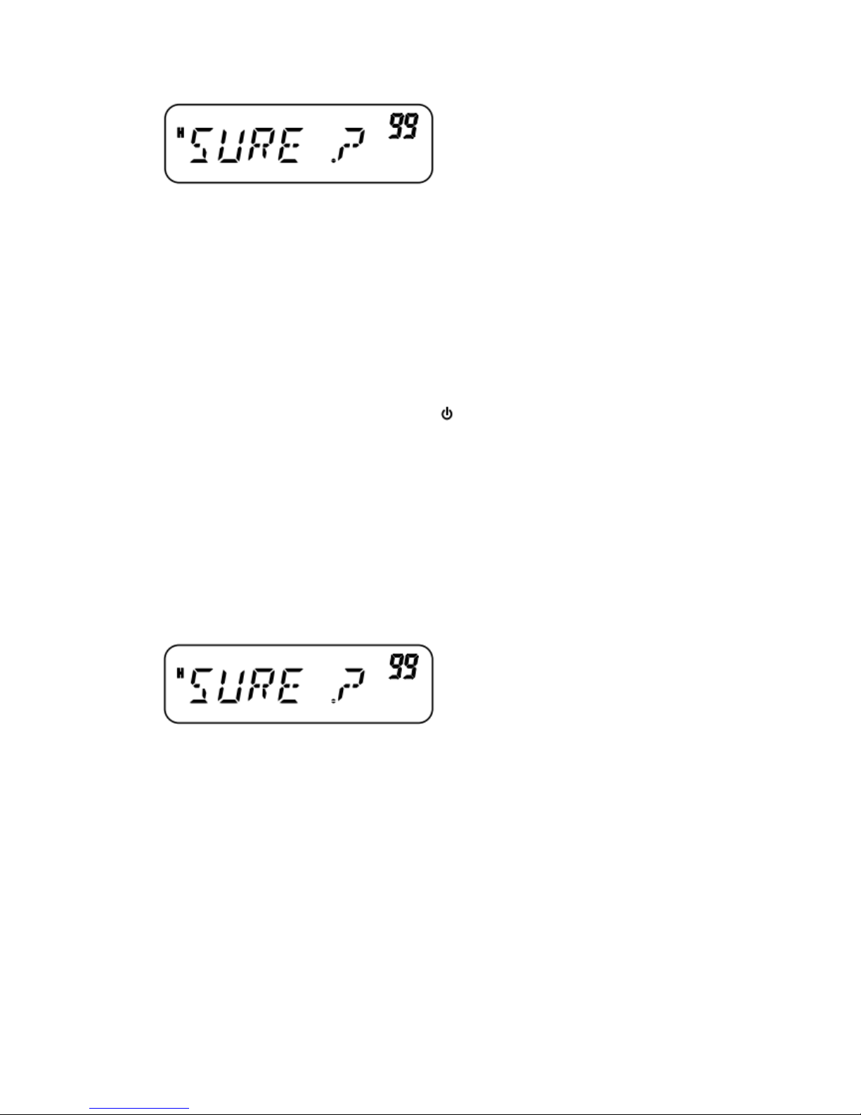
• Press any key other than [MENU] to cancel.
4 Press [MENU] to reset the transceiver.
“WAIT” appears momentarily.
VFO RESET
This resets the transceiver parameters excluding the DTMF Memory, the Memory channel
contents, and the Call channel contents. There are two methods available for resetting the
transceiver.
Note: Menu No. 7 (P.VFO) and Menu No. 10 (OFFSET) return to the factory default values.
VFO Reset Method 1:
1 With the transceiver power OFF, press [VFO] + [ ] (Power).
•The VFO reset confirmation message appears. 2 Press [VFO].
•“SURE?” appears.
•Press any key other than [VFO] to cancel.
3 Press [VFO] again to reset the transceiver.
“WAIT” appears momentarily.
VFO Reset Method 2:
1 Press [F], [MENU] and turn the Tuning control to select Menu No. 99 (RESET).
2 Press [MENU] and turn the Tuning control to select“VFO”.
3 Press [MENU].
•“SURE?” appears.
•Press any key other than [MENU] to cancel.
4 Press [MENU] to reset the transceiver.
TROUBLESHOOTING
The problems described in the following tables are commonly encountered operational
malfunctions. These types of difficulties are usually caused by improper hook-up, accidental
incorrect control settings, or operator error due to incomplete programming. These problems are
usually not caused by circuit failure. Please review these tables and the appropriate section(s) of
this instruction manual before assuming your transceiver is defective.
Page 71
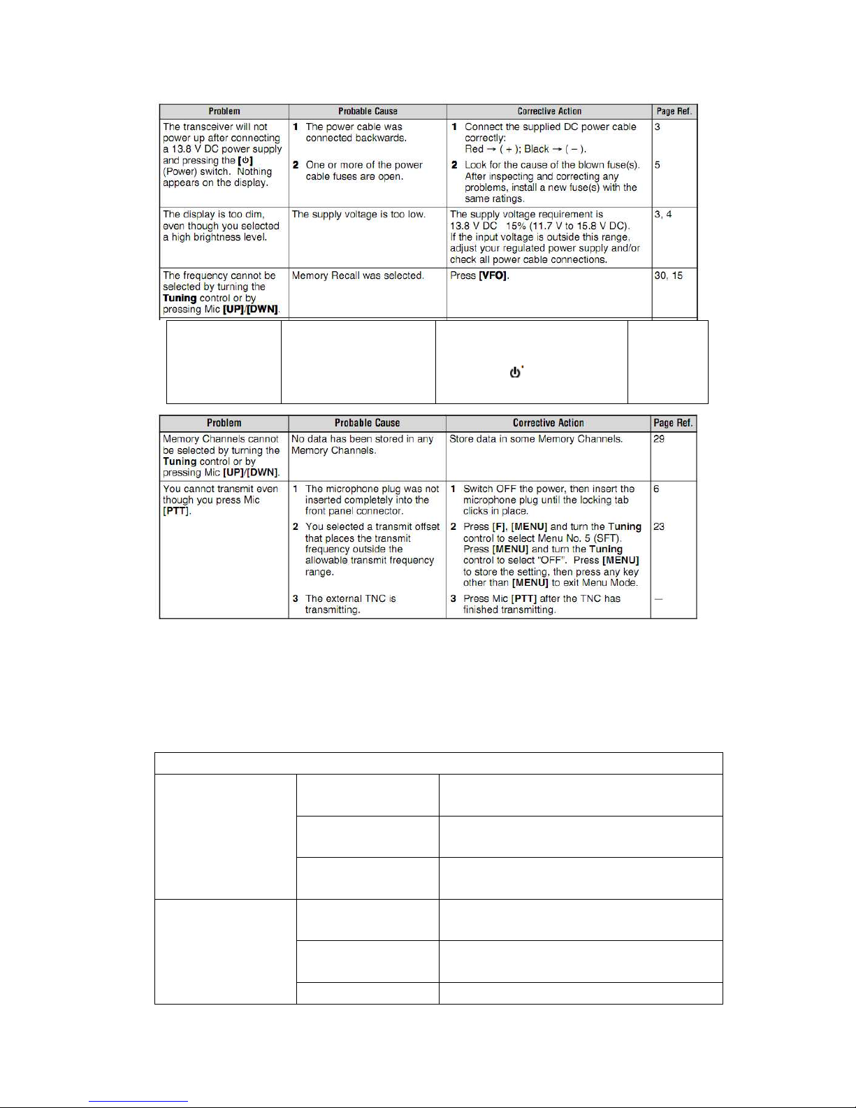
Most
keys/buttons or
Tuning control
do not function
1 One of the Lock
functions is ON.
2 The transceiver is in
channel display mode.
1 Unlock all Lock functions
2 With the transceiver power
OFF, press [ ](power)+[REV]
to exit Channel Display mode.
53,58,64,37
SPECIFICATIONS
Specifications are subject to change without notice due to advancements in technology.
General
TC-271(M3 market
models)
136~174MHz
TC-271(C market
models)
400~430MHz
Tx Frequency Range
TC-271(C2 market
models)
440~480MHz
TC-271(M3 market
models)
136~174MHz
TC-271(C market
models)
400~430MHz
Rx Frequency Range
TC-271(C2 market 440~480MHz
Page 72
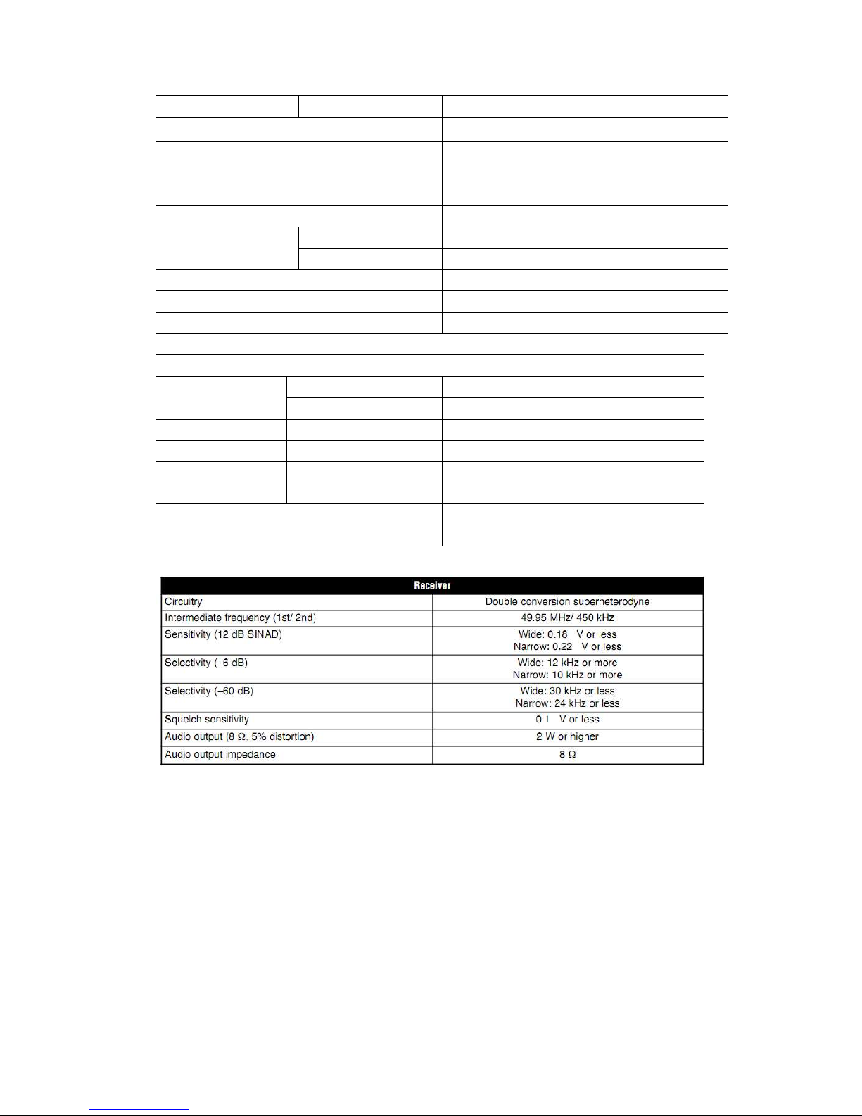
models)
Mode F3E (FM)
Antenna Impedance 50
Usable Temperature Range
-20℃~+60℃(-4°F~+140°F)
Power Supply
13.8V DC±15% (11.7~15.8V)
Grounding Method Negative ground
Transmit (Max.) 13A or less Current
Receive (2W output) 1.0A or less
Frequency Stability Within2.5ppm
Size (W×H×D, projection not included) 160×43×137mm
Weight Approx. 1.2kg
Transmitter
High VHF: 60W/UHF: 40W Power Output
Low Approx. 25W
Modulation Reactance
Spurious Emissions -60dB or less
Max. Frequency
Deviation
wide: ±5kHz
narrow: ±2.5kHz
Audio Distortion (60% modulation) 3% or less
Microphone Impedance 600
Page 73

INDEX
1750 Hz ................................
Accessories
Optional ............................
Supplied ............................
All-Channel Scan ..................
Automatic Power Off .............
Automatic Repeater Offset ....
Automatic Simplex Check .....
Automatic Dialer ...................
Band Scan ............................
Beat Shift ..............................
Beep Function ......................
Busy Channel Lockout ..........
Call Channel
Changing ..........................
Recalling ...........................
Call Scan ..............................
Channel Display ...................
Continuous Tone Coded
Squelch System (CTCSS)
Freq. ID Scan ....................
Selecting a Frequency ......
Using ................................
Data Communication
Speed ...................................
Digital Code Squelch (DCS)
Code ID Scan....................
Selecting a Code ...............
Using ................................
Display
Backlight ...........................
LCD ..................................
Dual Tone Multi-Frequency(DTMF)
Automatic Dialer ..................
Confirming a Stored Number ...............................
Lock ....................................
Manual Dialing ....................
Monitor ................................
Pause Duration ...................
Storing in Memory ...............
Tone Transmission Speed ...
Transmitting a Stored Number ...............................
TX Hold ...............................
Page 74

Frequencies, Selecting
Direct Frequency Entry........
MHz Mode ..........................
VFO Mode ..........................
Frequency Step Size ..............
Full Reset ...............................
Fuses, Replacing .....................
Group Scan ............................
Installation ...............................
Accessory Connections ........
Antenna Connection.............
DC Power Cable Connection, Fixed Station ........................
DC Power Cable Connection, Mobile ..................................
PC Connection .....................
TNC Connection ..................
Keypad Direct Entry ................
Keys and Controls ...................
Lock Function ........................
Maintenance ..........................
Manual Dialing .......................
Memory Channels
Clearing .............................
Lockout ..............................
Naming ..............................
Recalling ............................
Storing, Odd-split ...............
Storing, Simplex .................
Transfer to VFO .................
Menu
Access ...............................
Function List .......................
MHz Mode .............................
MHz Scan ..............................
Microphone
Control ...............................
Lock ...................................
PF Keys .............................
Narrow Band FM ...................
Offset
Automatic Repeater ...........
Direction .............................
Frequency ..........................
Power-on Message ................
Power ON/ OFF .....................
Page 75

Priority Scan
Programming .....................
Using .................................
Program Scan
Frequency Range ..............
Using .................................
Programmable Function (PF) Keys ..............................
Repeater Operation ...............
Reset
Full ....................................
VFO ..................................
Reverse Function ..................
Scan
All-Channel ........................
Band ..................................
Call ....................................
Group .................................
MHz ...................................
Priority ................................
Program .............................
Resume Method.................
Specifications ........................
Squelch
Adjusting ............................
Hang Time .........................
S-meter ..............................
Time-out Timer (TOT) ............
Tone
1750 Hz Tone .....................
Activating ...........................
Freq. ID Scan .....................
Selecting ............................
Transmitting ...........................
Output Power .....................
Troubleshooting .....................
Tuning Control Unlock ...........
VFO
Mode ..................................
Programmable ...................
Reset .................................
Volume, Adjusting ..............
Weather Alert
Enabling .........................
Programming .................
 Loading...