

Hypro SERIES 5300C-X, SERIES 5321C, SERIES 5322C, SERIES 5324C Installation, Operation, Repair And Parts Manual
Page 1
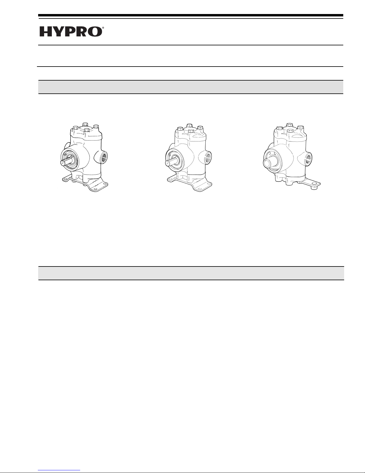
Series 5300C-X, 5321C, 5322C and 5324C
Small Twin®Piston and Plunger Pumps
Form L-0200P
Installation, Operation, Repair And Parts Manual
SERIES 5300C-X
Cast Iron Small Twin
Piston Pump
Max. Flow Rate: ..................1.5, 2.0, 2.5
Max. Pressure: ..........................500 psi
Max. Speed: ............................1725 rpm
Ports:................................1/2" NPT inlet
Max. Operating Temp. ................140oF
and 3.0 gpm
1/2" NPT outlet
Description
SERIES 5321C & 5322C
Cast Iron Small Twin
Plunger Pump
Max. Flow Rate: ........................2.2 gpm
Max. Pressure: ........................1000 psi
Max. Speed: ............................1725 rpm
Ports:................................1/2" NPT inlet
Max. Operating Temp. ................180oF
1/2" NPT outlet
7/05
SERIES 5324C
Cast Iron Small Twin
Piston Pump
Max. Flow Rate: ........................2.9 gpm
Max. Pressure: ..........................800 psi
Max. Speed: ............................1725 rpm
Ports:................................1/2" NPT inlet
Max. Operating Temp. ................140oF
1/2" NPT outlet
Safety Information
The following special attention notices are used to notify
and advise the user of this product of procedures that
may be dangerous to the user or result in damage to the
product.
TE: Notes are used to notify of installation, oper-
NO
ation,
or maintenance inf
ormation that is impor
but not safety related.
UTION:
CA
of a hazar
Caution is used to indicate the presence
h will or can cause minor injury or
whic
d,
property damage if the notice is ignored.
WARNING: Warning denotes that a potential hazard
exists and indicates procedures that must be fol-
y to either eliminate or reduce the haz
xactl
wed e
lo
ard, and to avoid serious personal injury, or prevent
future safety problems with the product.
ANGER:
D
Danger is used to indicate the presence
of a hazard that will result in severe personal injury,
death, or property damage if the notice is ignored.
tant
DANGER: DO NOT pump flammable or explosive
fluids such as gasoline, fuel oil, kerosene, etc. DO
NOT use in explosive atmospheres. The pump
should be used onl
y with liquids compatible with the
pump component materials. Failure to follow this
warning can result in personal injury and/or property dama
e and will v
g
oid the pr
oduct warranty
A pressure relief device, such as an unloader, relief
valve or balancing regulator must be installed on the
ailure to do so could
outlet side of the pump.
result in per
•
Be sure all exposed moving parts such as shafts,
sonal injur
F
y and/or v
oid the warranty
couplers and adapters are properly shielded or
-
guarded and that all coupling de
vices are securely
attached before applying power.
• Hollo
w shaft pumps mounted directly onto po
ented from rotating with the po
shaft m
ust be pre
v
shaft by means of a device such as a torque arm.
Pump m
ust float freely on the po
not be tied r
igidly to equipment on which it is mount
wer shaft and must
ed.
.
.
er
w
er
w
-
Page 2
• Do not exceed recommended speed, pressure and
L
d
temperature for pump and equipment being used.
• Periodically inspect the pump and the system
components. Perform routine maintenance as
required (see Maintenance section).
• Before servicing, disconnect all power, make sure
all pressure in the system is relieved, drain all liquids from the system and flush.
• Secure the discharge lines before starting the
pump. An unsecured line may whip, causing personal injur
y and/or property damage.
• Check hose for weak or worn condition before
each use. Make certain that all connections are
tight and secure.
Drive Source Installation
This manual will cover the installation of the basic drive
configurations available for the Hypro Small Twin
Piston and Plunger pumps. Consult the manufacturer
Belt/Pulley Drive Installation
Mounting Belts and Pulleys
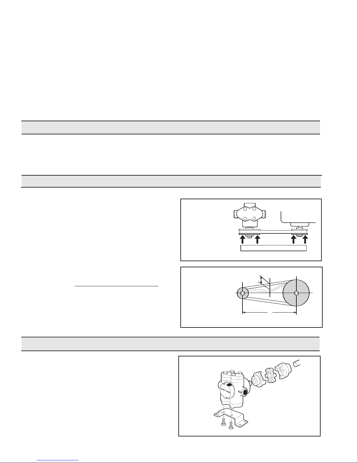
Mount pulleys as close to pump and motor engine shaft
bearings as possible. Check alignment with a straight edge
as shown (See Figure 1). Make sure that belt has proper
tension. (Too much tension will cause bearing wear; too little will cause slippage.) (See Figure 2). Check with belt
and pulley sources for specific recommendation.
To figure proper diameter of pump pulley, multiply
motor/engine RPM by diameter of the motor/engine pulley
and divide that figure b
Pump = Motor RPM x Motor Pulle
Pulley Size Desired Pump Speed
Refer to pump performance charts to determine desired
speed to obtain desired maximum flow.
y desired pump speed.
y Size
• Protect pump from freezing conditions by draining
liquid and pumping rust inhibiting solution, such as
antifreez
e, through the system, coating the pump
interior.
• Use only pipe, hose and fittings rated for the maxi-
um (or greater) PSI rating of the pump.
m
• Do not use these pumps for pumping water or
other liquids for human or animal consumption.
of your motor or engine for additional information.
Read all instr
uctions and general safety information
before attempting to install or operate the pump.
Four points of
contact indicate
alignment.
NOTE: Pump may
be mounted in other
orientations with
respect to the motor
or engine.
Figure 1
Push the belt midway between the
, check the
ys
pulle
deflection (d) and
adjust:
d = 0.016 x L
NOTE: Shaft rotation can be either clockwise or counterclockwise.
Direct Drive - Flexible Coupling Installation
First, slide coupling ends onto motor/engine and
pump shafts as far as possible (See Figure 3).
Mount motor/engine and pump onto base
pump or power unit so that shafts are aligned. Leave
enough space betw
pling disc to be inser
slide coupling ends over coupling disc. Leave clearance betw
Tighten scre
motor dr
horsepower required to operate pump. For gas
engine dr
een coupling ends and center disc.
ws in both coupling ends
, use couplings r
e
iv
, select couplings rated at three times
e
iv
the required pump horsepo
een ends of shafts to allo
When alignment is made
ted.
ated at least twice the
.
er
w
, shimming
w cou
or electr
F
.
Figure 2
,
CAUTION:
ic
For safety, always install a
shield over rotating shafts
and couplings.
Figure 3
-2-
Page 3
Direct Drive - Hollow Shaft Installation
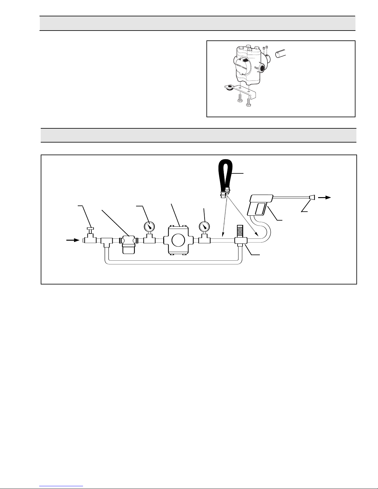
Hollow shaft models mount directly on the motor or
engine shaft (See Figure 4). Adapters are available to
convert some solid shaft models for direct shaft mounting. After mounting the pump, always turn it by hand
to make sure the pump is operating freely. Never
apply power to a pump that appears to be stuck.
CAUTION: Use a torque arm to keep the pump
from rotating with the shaft. The pump must be
allowed to float on the shaft and must not be tied
rigidly to the equipment on which it is mounted.
System Installation
Figure 4
Pulsation
Dampener
UTION:
CA
For safety, always install a shield
over rotating shafts. Or enclose
the pump/motor assembly inside
a housing.
Inlet
Pressure
Regulator
Line
Strainer
Compound
Gauge
Figure 5
Piston Pump Installation
Accessories should be installed with solid piping and be
mounted as close to the pump as possib
be used r
ight after accessories.
NOTE: If remaining installation is solid piping, a two to
oot length of hose m
our f
f
ust be installed between
accessories and solid piping.
Hose
Selection of the right size and type of hose is vital for good
performance. Be sure to hook up to the proper ports on the
pump (note markings “IN” and “OUT” on pump castings).
Suction Hose
ys use genuine suction hose compatible with the fluids
a
Alw
being pumped and at least the same inside diameter as
pump ports. If the suction hose is over 5 feet long, use the
xt larger siz
ne
e hose
eep the suction hose as short as pos-
K
.
sible and restrictions such as elbows, check valves, etc. at a
minimum.
Discharge Hose
High pressure pumps require the use of special high pressure discharge hose (2 rayon braid or equivalent). Use a
ated at least 50% g
hose r
reater than the highe
Pump
IN
Bypass Back to Inlet
The hose m
.
le
st oper
ust
ating
OUT
Filled
Pressure
Gauge
Nozzle
Spray
Gun
Unloader
Valve
pressure required of pump.
sure is 200 psi, use discharge hose r
king pressure
or
psi w
Example: If required pump pres-
ated at minim
.
um of 300
Unloader Valve
The unloader has a v
er
y impor
tant saf
piston pump hookup. The unloader valve protects the pump
by unloading pressure when the gun is shut off or discharge
is otherwise blocked. This saves the pump and power
because the liquid is b
ypassed at a v
gun is to be shut off for more than 5 minutes, install a pump
protector in the inlet side or stop the pump to pre
buildup. The length of time may vary due to the original temperature of the fluid being pumped.
ety function in y
y low pressure. If the
er
ent heat
v
Strainers
Use a suction line strainer with at least 3 to 5 times the suction port area in open screen area. For example, an area of
approximately 1.1 to 1.9 square inches for a 1/2" suction
port. Be sure the screen is suitable for the liquid being
pumped. Keep the filter clean. A clogged strainer will cause
mance and
vitation, which usually leads to a poor perf
ca
ear of the pump par
w
-3-
.
ts
or
our
Page 4

Compound Gauge (Optional)
The pump should not be subjected to high suction line vacuums. To check on this, install a compound gauge at pump inlet.
For ultimate performance and life, the vacuum should be limited to 5 inches of mercur
premature product f
y. High vacuum conditions may cause
ailure and void warranty.
Pulsation Dampener
This device absorbs the shock and smooths out the pump discharge pulsations, providing smoother operation. For the proper operation of many unloader valves, the pulsation dampener
should be installed on the discharge side downstream from the
unloader valve. However, for maximum system protection, the
pulsation dampener may be installed upstream from the
Operation
Priming
If the liquid is below level of the pump, some means
should be provided in installation to prime pump, such
as a foot valve or check valve to hold prime. Keep suction lift to minimum and avoid unnecessary bends in the
suction line. Before starting pump, make sure air bleeder valve or spray gun is open, or unloader valve is
adjusted to its lowest pressure. After starting pump,
open and close gun several times if necessary to aid
priming the pump. If pump does not prime within a few
seconds, stop motor and inspect installation for suction
line leaks or obstructions. Make sure that strainer is not
clogged. Be sure that suction line is not obstructed,
kinked or blocked.
If the pump is to operate hours at a time, check frequently for:
unloader valve, provided the unloader valve will function properly. The dampener can be mounted vertically or horizontally.
Pressure Regulator
Use a pressure regulator to limit incoming pressure to 20 psi
when equipped with a suction side injector
and horsepo
apply when incoming pressure e
wer figures in pump performance tables do not
xceeds 40 psi.
. Volume, pressure
Pressure Gauge/Dampener
Use gauge capab
sure. Use a silicone-filled gauge or a gauge dampener to protect the gauge needle against pressure surges and provide
easier reading.
While this flushing is not absolutely necessary for short
periods of idleness (as overnight), it is good practice to
clean the pump after each use to prevent deposits from
forming and damaging the pump. The antifreeze not
only coats the interior of the pump with an inhibitor, but
acts as a lubricant as well, keeping valves from sticking
- and protecting against any remaining moisture freezing in cold weather.
For infrequent use and before long periods of storage,
drain pump thoroughly. Open any drain plugs, remove
suction hose from liquid, and run pump “dry” from 0 to
30 seconds
should be injected into the pump before both ports are
plugged and the pump is stored. Then, plug both ports
to keep out air until pump is used again.
le of reading double the pump working pres-
(not longer). Once again, a rust inhibitor
1. Adequate liquid supply. Pump must not run dry for
more than 30 seconds.
2. Temperature rise. Overheating is harmful to bearings and piston cups.
NOTE: Models 53702 and 53703 Inlet Requirements:
Pressure feed 20 to 100 psi.
Care of Pump
mance
our pump will last longer and giv
Y
en care of
when proper
depends on the liquid being pumped and when pump
will be used again.
cleaning installation (where each application is f
by a clear water rinse), the pump will be kept clean.
After each use
for the liquid just pumped. Follow with a clear water
rinse. This is especially important for corrosive chemi-
Then flush out pump with a 50% solution of auto
.
cals
motive ethylene glycol-type radiator antifreeze containing a rust inhibitor, or use a commercial rust inhibitor
such as FLUID FILM.
ly tak
In a nor
, flush pump with a neutr
mal car w
e best perf
Proper pump care
.
ash or detergent
or
ed
w
ollo
alizing solution
Lubrication Schedule
Use a grease gun to lubricate Hypro Series 5300 and
5324 Piston Pumps and Series 5321 and 5322 Plunger
Pumps. DO NOT USE AIR-POWERED GREASE
GUNS as they develop too much pressure and may
cause damage to the sealed cam bearing.
Lubrication
EXCEPTION:
required, use one of these g
Mobile FM#2 Keystone (Penwalt Corp.) Nevastane SP
Medium.
With a scre
grease to outer diameter surface of cam bearing at top
and bottom where bear
Do not grease excessively.
k periodically and scrape out (do not WASH out)
Chec
any excess grease from pump cavity.
In applications where FDA approval is
vron FM#2,
reases:
Lubricate every 50 hours or monthly.
er or flat tool, apply a generous dab of
iv
wdr
ing contacts connecting rod.
Che
-4-
Page 5
Repair Instructions
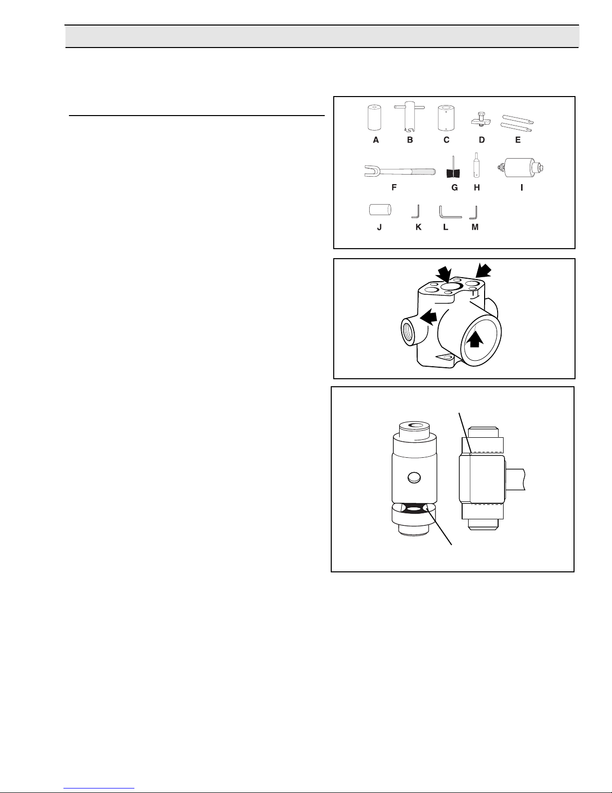
Recommended Repair Tools
For Hypro Small Twin Piston/Plunger Pumps
Ref. Part No. Description 5321 5324 5300
A 1055-0005 Seal Ring Seating Tool •
B 3010-0052 Valve Cage Extractor • • •
C 3010-0061 Main Bearing Support Tool • • •
D 3010-0063 Cam Bearing Support Tool • • •
E 3010-0064 Support Bars (Qnty 2) • • •
F 3010-0065 Pry Bar • • •
G 3010-0066 Wire Brush • • •
H 3010-0067 Wire Brush Holder • • •
I 3010-0071 Valve Seat Extractor • • •
J 3010-0222 Seal Ring Seating Tool •
K 3020-0001 3/16" Allen Wrench • • •
3020-0003 1/8" Allen Wrench • • •
L
3020-0009 1/16" Allen Wrench • • •
M
Used for Series
Recommended Shop Tools
Bench Press
, Arbor Press, Air Gun or Electric Hand
Drill, Metal Pipe, Support Fixture, (3" diameter x 4 1/2"
high), Ratchet Handle Wrench with 9/16" Hex Socket,
Bolt (3/8" diameter x 4 1/2" long), No. 320 Grit Emory
Cloth, Pliers, Small Knife, Large File, Claw Hammer,
Standard Screwdriver, Lubricating Spray (WD-40 or
LPS), Wire Brush (hand or machine), Stationary Belt
Sander, and Cleaning Solvent Tank (recommended)
Inspection of Pump Parts
When disassembling pump, thoroughly inspect all
parts and replace if necessary, with special consideration given to the following areas:
Figure 6 Recommended Repair Tools
Figure 7
Use a feeler gauge on
this end to check
amount of space.
1. Inspect Pump Body for erosion at O-ring seal
points in Valve and Piston bores. Check for wear
resulting from Main Bearings turning in Housing,
especially the Front Bearing area closest to the
Cam Bearing. Check for cracks in the Pump Body,
ly at the discharge port and along the
ticular
par
casting seam (See Figure 7).
2. Inspect for excessive wear on the Cylinder Heads.
This can result from erosion and/or valve seat
hammer (See Figure 7).
3. Inspect for pitting and general wear in the Unitized
Valves, particularly where the Poppets seal
against the seat. If this area is worn, replace all
f
our Valves (See Figure 7).
4. Inspect the Connecting Rod. If there is more than
.007" wear in the total space between the
Connecting Rod and Cam Bearing, the
Connecting Rod should be replaced.
mined using a f
deter
eeler gauge
This can be
The Cam
.
Bearing should also be inspected as a bad cam
ing is the most common cause of a damaged
bear
n Connecting Rod results
or
Connecting Rod.
A w
in low volume, low pressure, a hammering sound
and the pump running hot (See Figure 8).
k this area f
Chec
wear on both ends.
or
Figure 8
ear
Inspect Cr
5.
ankshaft Assemb
or gener
ly f
al w
Rotate Cam Bearing and Main Bearings to check
or roughness due to moisture contamination or
f
lac
k of g
rease
If main bear
.
ings do not turn
smoothly or appear to be damaged, they should
be replaced. If cam bearing is damaged, a new
ankshaft Sub-assemb
Cr
ly should be installed and
the connecting rod inspected for wear (See Figure
8).
NOTE: Always use new O-rings, Cups, Seal Rings,
Support Rings, Guides, Washers, and Piston Cap
Screws. If new Valves are needed, always replace
.
the complete set of f
our
.
-5-
Page 6
Series 5300X, 5321, 5322, & 5324
Disassembly, Repair, & Reassembly Instructions
NOTE: Due to variations in each model's Piston or
Plunger Stack, differences in the instructions for
each model will be denoted with italics and brackets.
HAZARDOUS SUBSTANCE ALERT: Always drain
and flush pump before servicing or disassembly.
Valve Assembly Removal:
1. Place the Pump upright in a bench-mounted vise
with the Safety Cover facing out; then, using a
9/16" wrench, remove the Cylinder Head Bolts.
2. Remove the Cylinder Head.
3. Using a screwdriver or knife, remove the Cylinder
Head O-ring from the Cylinder Head.
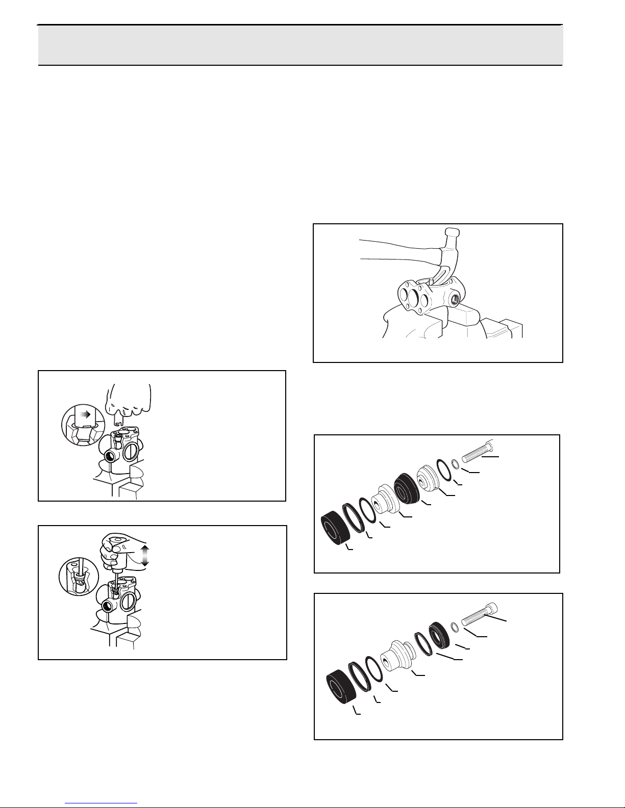
4. Using the Seat and Cage End Valve Extraction
Tools, remove the Unitized Valve Assembly from
the Pump Body (See Figures 9 and 10).
6. Turn the Pump over and repeat Steps 1 through 5.
7. Position the Pump horizontally in the vise with the
Safety Cover side up.
8. Use a claw hammer to remove the Grease fitting
(See Figure 11). In most cases, the Grease Fitting
is damaged during removal and must be replaced
[At this time
, remove the Connecting Rod in
Models 5321 & 5322].
Figure 11
To remove Valve Cage.
Hook prongs of Valve
Cage Extractor under
three webs of the Valve
Cage and pull up with a
twisting motion.
Figure 9
To remove Valve Seat.
Hook Valve Seat Extractor
under Seat and work out
with an up and down
motion.
Figure 10
Rotate the Pump Shaft so the Cam Bearing is in
5.
the upstrok
wrench, remo
e position;
e the Cap Scre
v
Assembly for Models 5300X and 5324 [
then using a 3/16’’ Allen
w from the Piston
For Models
5321 & 5322, remove the Plunger from the Pump
ed
Body after the Cap Scre
w is remo
v
].
Piston Sleeve Assembly Removal and
Cleanup (5300X and 5324 only)
See Figures 12 and 13 for Piston Stack Components
Cap Screw
asher
W
O-ring
Cup Spreader
Cup
Cup Bac
O-ring
Seal Ring
Guide
Figure 12
O-ring
Seal Ring
Guide
Figure 13
king Plate
Cap Screw
Washer
Cup
Support Ring
Cup Holder
-6-
Page 7
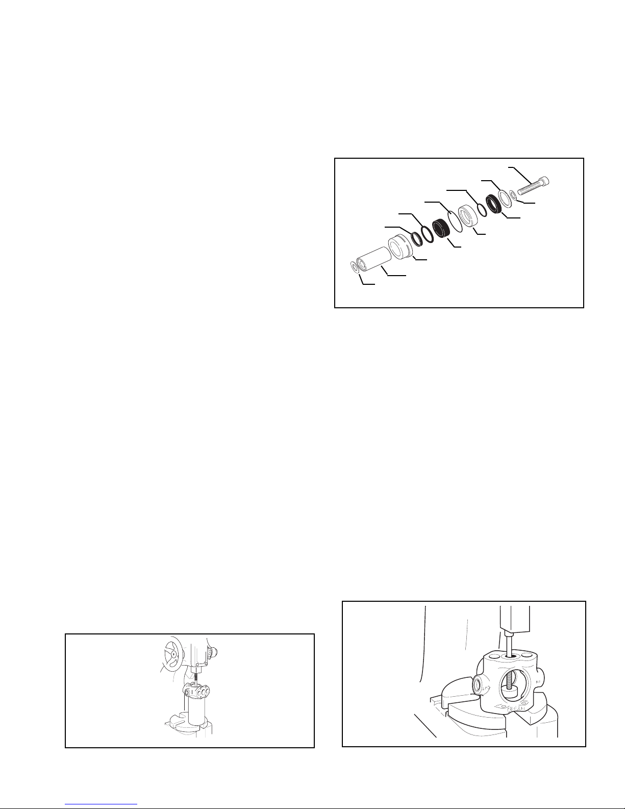
Leave the pump body horizontal in the bench vise
1.
to remove the Cylinder Sleeves and Piston
Assemblies. Make sure the Cam Bearing is in the
upstroke position. Place one of the metal bars
vided in the tool kit on the Cylinder Sleeve.
pro
Using a hammer, gently tap the Cylinder Sleeve
2.
out of the Cylinder Head end of the pump body.
The Piston will also come out with the Cylinder
sleeve.
Place a bolt 3/8" in diameter by 4-1/2" long thread-
3.
ed end up on the Crankshaft Cam Bearing; then,
using the arbor press ram on the bolt, push the
Crankshaft Assembly out of the Pump Body (See
Figure 14).
Plunger Cartridge Removal/Disassembly/
Reassembly (Series 5321 and 5322 only)
See Figure 15 f
or Plunger Cartridge Components
3. Turn the pump around in the vise and repeat Steps
1 and 2.
4. Remove the Connecting Rod.
5. Remove the Piston Assembly from the Cylinder
Sleeve by pushing it out with your fingers; then
remove the washer.
6. Clean the cylinder sleeves using the burnishing
adapter supplied with the tool kit. The adapter is
mounted to an electric motor shaft. Insert the
Cylinder Sleeve (brass retainer end facing out) into
the furnishing adapter and polish the inside sur-
ace using a No. 320 grit emery cloth. Use a wire
f
brush to clean the outside of the cylinder sleeve.
Upon inspection, if pitting or scratches still show
on the inside of the cylinder sleeve, the cylinder
sleeve must be replaced along with the cylinder
sleeve o-ring.
Crankshaft Assembly Removal
(All Models)
WARNING: Special attention should be exercised
when working with retaining rings. Always wear
ety gog
saf
sion-loaded fastener
1. Place the pump on a flat surface with the shaft
side facing up; then remove the retaining ring from
the bearing bore.
gles when working with spring or ten-
s or de
vices.
Cap Screw
Support Ring (Brass)
Inner Support Ring
O-ring
Seal Ring
O-ring
Guide Retainer (Brass)
Washer (5322 ONLY)
Plunger: Steel (5321), Ceramic (5322)
Seal Retainer (Brass)
Guide
Washer
Seal
Figure 15
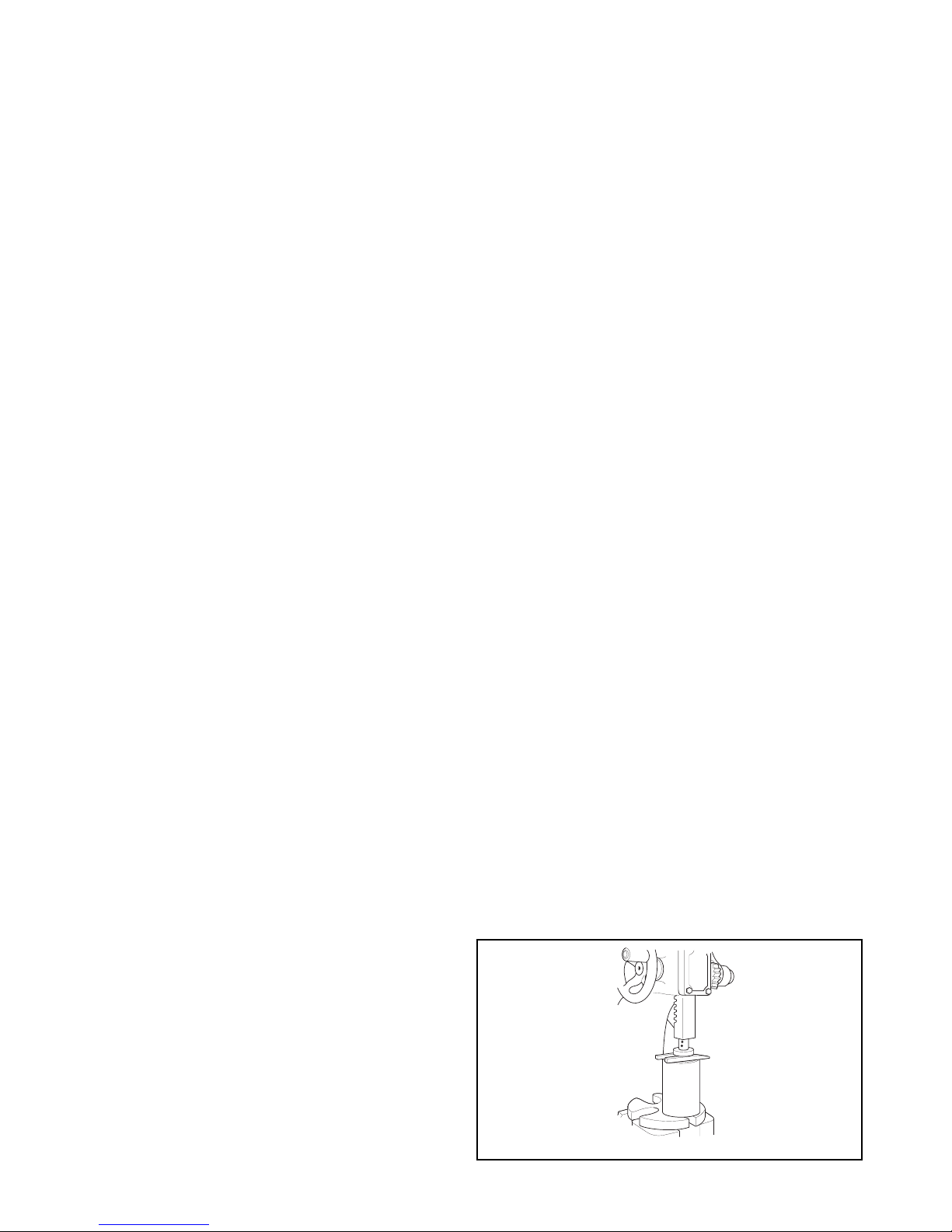
To Remove the Plunger Cartridges from
the Pump Body:
1. Position the pump upright on the arbor press with
the Safety Cover opening facing out.
2. Place the Plunger Cartridge Extractor Tool,
machined side down, on the Guide Retainer inside
the pump body.
3. Place the bolt threaded-end down through the
Plunger Bore on the other end of the pump until it
rests in the counter-sink hole on the Cartridge
Extractor Tool.
4. Place the arbor press ram on the bolt head and
push both the Seal and Guide Retainer out of the
pump body (See Figure 16).
5. Turn the pump over and repeat Steps
1 through 4.
2. Using a metal pipe 3" in diameter by 4-1/2" high as
a support fixture, place the pump on the fixture,
shaft side down. Position the fixture with pump on
the arbor press (See Figure 14).
Figure 14
Figure 16
-7-
Page 8
To Disassemble the Guide and Seal
Cartridges:
Remove the Guide from the Guide Retainer by
1.
pulling it out with one finger.
NOTE: If the guide does not come out in this manner, use a screwdriver and a hammer to gently
break off a section of the Guide
to damage the Guide Retainer. The remaining portion of the Guide will then fall out.
With a small knife blade, remove the O-ring/Seal
2.
Ring combination from the Guide Retainer.
3. Using a small knife blade, remove the Brass
Suppor
from the Seal Retainer
Inspect and clean the Brass Guide and Seal
4.
Retainers. Clean them with a wire brush and
check them for burrs and nicks. Use 320 grit
emery cloth to remove burrs.
t Ring and Support Ring/Seal combination
.
, being careful not
Clean-up of the Pump Body and Heads (All
Models)
1. Using the port wire brush with an air gun or electric
hand drill, clean the outlet port and inlet port, plus
the valve and piston bores in the Pump Body.
Use a hand file or belt sander to clean corrosion
2.
and rust from the top and bottom of the Pump
Body and the bottoms of the cylinder Heads.
3. After performing Steps 1 and 2, Hypro recommends that the pump Body and Cylinder Head be
further cleaned in a solvent tank to remove any
remaining rust and corrosion particles.
NOTE: If the solvent cleaning is not performed, the
valve and piston bores must be wiped as clean as
possible.
Crankshaft and Main Bearing
Disassembly/Reassembly (All Models)
To Reassemble the Plunger Cartridges:
1. Lightly lubricate the O-ring and place it around the
Seal Ring.
2. Position the O-ring/Seal Ring combination in the
Guide Retainer at a 45 degree angle.
3. Using the Guide, seat the O-ring/Seal Ring
Combination into the Guide Retainer, leaving the
Guide in the Guide Retainer.
Place the Guide Retainer on a flat surf
4.
the exposed portion of the Guide is down.
Place the cap screw end of the Plunger into the
5.
Guide Retainer and press it through until the
Plunger is flush with the bottom of the Guide
Retainer.
6. Turn the Cartridge over and push the Guide
Retainer down the Plunger until it is flush with the
bottom of the Plunger.
ace so that
Disassembly:
1. To remove the Front Main Bearing from the
Crankshaft, position a pipe support fixture on the
arbor press; then, place two metal bars parallel to
each other, one on each side of the fixture (See
Figure 17).
2. Place the Crankshaft Assembly in the fixture, drive
end up, with the metal bars between the Bearing
and fixture to support the Outer Bearing (See
Figure 17).
Make sure the metal bar
TE:
NO
Retaining Ring on the Crankshaft.
Using the arbor press
3.
through the Bearing (See Figure 17).
WARNING: Special attention should be exercised
when w
saf
loaded fasteners or devices.
orking with retaining rings. Always wear
ety gog
gles when w
orking with spring or tension-
s do not touc
, press the Cr
h the
ankshaft
Seal Retainer Cartridge:
Place the beveled side of the Inner Support Ring in
1.
the grooved side of the Seal; then, place the Seal
Retainer over the Support Ring side of the Support
Ring/Seal combination.
2. Press the above items in with your fingers until the
Support Ring/Seal combination bottoms out inside
the Seal Retainer
3. Place the Brass Support Ring on the open side of
the Seal Retainer.
.
Figure 17
-8-
Page 9
4. Remove the first Retaining Ring on the Crankshaft
with a pliers and the second Retaining Ring with a
screwdriver.
Press out the back Main Bearing in the same man-
5.
ner as the front Main Bearing (Refer to Steps 1
through 3).
6. Remove the Slinger Ring by working it off the Shaft.
Reassembly
Install the back Main Bearing first. Place the
1.
Bearing on the small opening end of the Main
Bearing Support Tool with the Slinger Ring on top
of the Bearing, and position it on the arbor press.
WARNING: Special attention should be exercised
when working with retaining rings. Always wear
safety goggles when working with spring or tension-loaded fasteners or devices.
Turn the Pump and Main Bearing Support Tool
10.
over so that the Safety Cover side of the pump is
facing up.
Position the Cam Bearing Support Tool with the
11.
bolt head down over the Safety Cover opening on
the pump body
.
Figure 19
12. Turn the bolt down by hand until it comes in contact with the Cam Bearing.
2. Place the Crankshaft in the Bearing and use the
arbor press ram to press the Crankshaft through
the Bearing until the Retaining Ring can be
installed in the second groove of the Crankshaft
(See Figure 18).
NOTE: Make sure the Slinger Ring does not touch
the Cam Bearing on the Crankshaft when installing
Retaining Rings.
3. Install both Retaining Rings on the Crankshaft.
Figure 18
Place the Pump Body
4.
, Safety Cover side down, on
the arbor press.
13. Use the arbor press ram to press down on the bolt
in the Cam Bear
Main Bear
ing Support Tool to push the front
ing into the pump bearing bore until it
comes in contact with the first retaining ring on the
ankshaft.
cr
14. Turn the pump over to install the Retaining Ring in
the pump bearing bore.
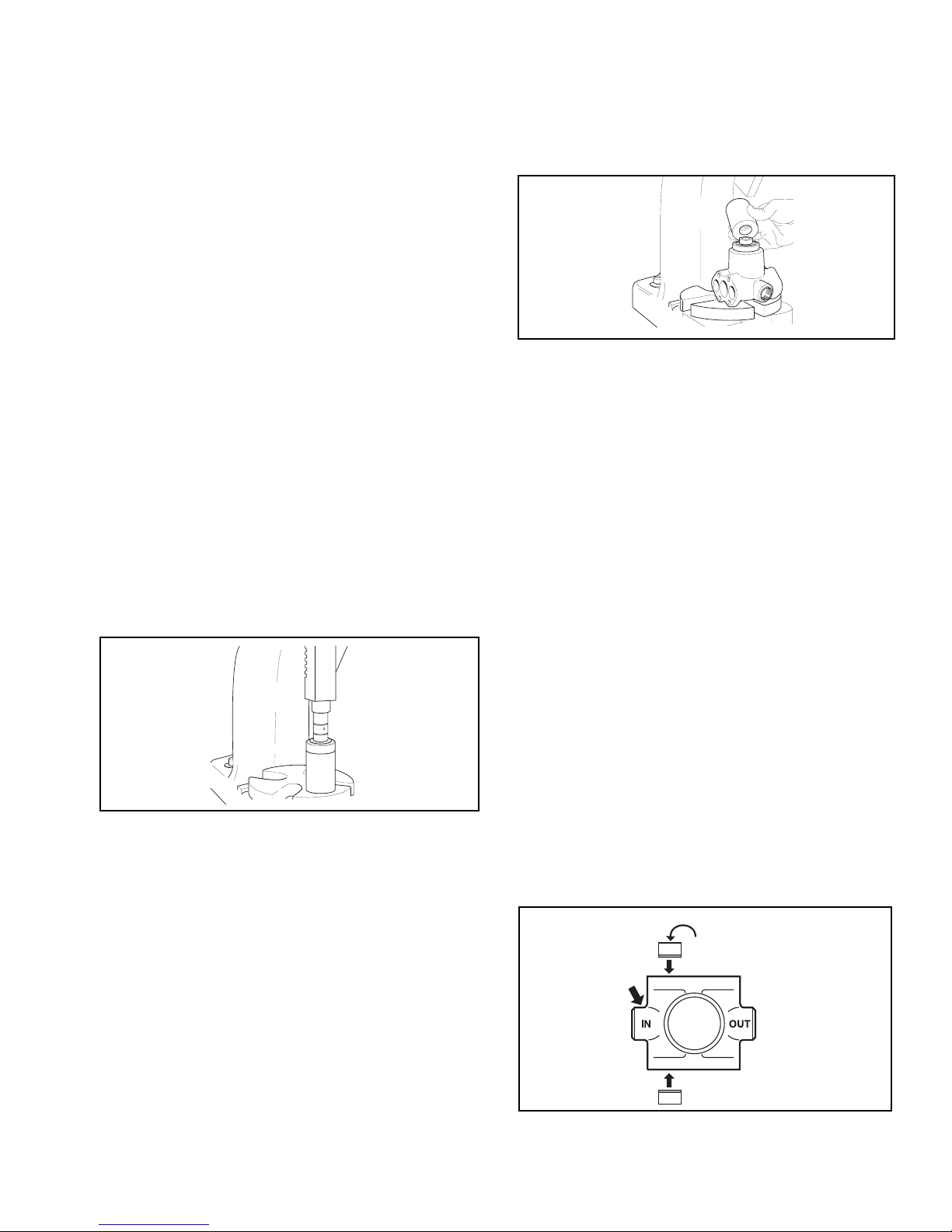
Valve Assembly Installation
1. Lubricate the Pump Body Valve Bores.
2. Install the Valve Assemblies into the
INLET side
valve bores with the plastic valve cage portion facing UP (See Figure 20).
3. Install the Valve Assemblies into the
OUTLET side
valve bores with the metal valve seat portion facing UP (See Figure 21).
4. Apply a small amount of grease to the top and bottom inside surf
aces of the Connecting Rod.
area where the Cam Bear
ing comes in contact
(The
with the Connecting Rod.)
Place the Cr
5.
ankshaft, Bac
k Bear
bearing bore of the Pump Body.
6. Place the Main Bearing Support Tool , large opener the Crankshaft.
v
wn, o
ing do
Use the arbor press ram to press the Crankshaft
7.
Assembly into the bearing bore of the pump body
until it bottoms out.
Place the front Main Bear
8.
ing on the Cr
it touches the pump body.
9. Place the smaller opening end of the Main Bearing
Support Tool over the Crankshaft (See Figure 19).
ing do
ankshaft until
wn, into the
Plastic Valve
Cage points Up.
Figure 20
-9-
Page 10
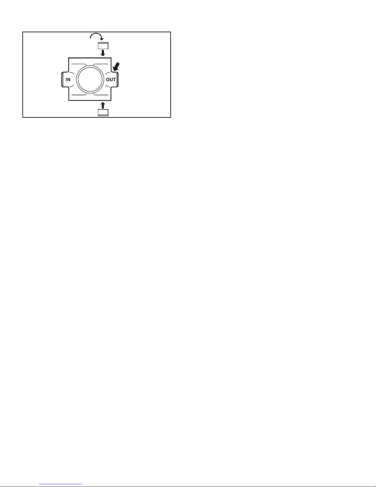
Place the Connecting Rod on the Cam Bearing.
5.
Place the Cup Spreader end opposite O-ring in the
12.
Cup inside the piston bore.
Metal Valve
Seat Points up.
Figure 21
Cylinder Sleeve and Piston Stack
Installation (Series 5300X and 5324 only)
NOTE: Clean the cylinder sleeves using the
Burnishing Adapter pr
Burnishing Adapter is to be mounted on an electric motor shaft.
1. Insert the Cylinder Sleeve (Brass Retainer End
out) into the Burnishing Adapter and polish the
inside surface using a No. 320 grit emery cloth.
2. Use a wire brush to clean the outside of the
Cylinder Sleeve.
ovided with the tool kit. The
13. Place the Washer on the Piston Cap Screw, insert it
through the Piston Assembly, then tighten it to 130
in. lbs. of torque.
4. Turn the Pump over and repeat Steps
1
2 through 13.
Plunger Assembly Installation
(Series 5321 and 5322 only)
NOTE: Make sure the Cam Bearing is in the
upstroke position when installing the Cylinder
Sleeves and Piston Assemblies.
1. Place the assembled Guide Retainer Cartridge and
Plunger into the plunger bore of the Pump body,
making sure the Plunger and Connecting Rod seat
together proper
2. Lubricate the O-ring and place it on top of the Guide
Retainer Cartridge.
3. Place the Seal Retainer Cartridge over the Plunger
(beveled side down), and press it by hand into the
Pump Plunger bore.
4. Place a Washer on the Plunger Cap Screw, insert it
through the Plunger and tighten it to 100 to 115 In.
Lbs. of torque.
ly inside the Pump Body.
NOTE: Upon inspection, if pitting or scratches still
show on the inside of the Cylinder Sleeve, the
Cylinder Sleeve and the Cylinder Sleeve O-ring
should be replaced.
3. Insert the Cylinder Sleeve into the cylinder bore of
the Pump Body.
4. Lubricate and place a new Cylinder Sleeve O-ring
.
e
on top of the Cylinder Slee
5. Place a Brass Retainer on top of the O-ring.
6. Insert the Guide into the Cylinder Sleeve, making
sure the Guide is properly seated on the
Connecting Rod inside the Pump Body.
7. Place the Seal Ring at a 45 degree angle on top of
the Guide; then, using the Seal Ring Seating Tool,
press the Seal Ring into the Cylinder sleeve.
8. Lubricate the O-ring and place it on the Cup
king Plate
Bac
Install the Cup Bac
9.
Ring in the piston bore, O-ring end down.
.
v
king Plate on top of the Seal
5. Turn the Pump over and repeat Steps
1 through 4.
Head and Grease Fitting Installation
(All Models)
1. Install the O-ring into the Pump Cylinder head.
2. Place the Pump Body upright in a vise; then, place
the Head on the Pump Body.
Secure the head to the Pump Body with the Head
3.
Bolts; then, alternately and evenly (in a criss-cross
pattern) tighten the head Bolts.
4. Turn the Pump over and repeat Steps
5. To install the Grease Fitting into the Cam Bearing,
place the pump on the arbor press with the Safety
Cover side facing up; then press the Grease Fitting
in with the arbor press r
6. Grease the pump according to the Lubrication
uctions.
Instr
Install the saf
7.
ety cover.
am.
1 through 3.
10. Lubricate the Cup and set it on top of the Cup
king Plate inside the piston bore
Bac
11. Lubricate the O-ring and install it on the Cup
Spreader.
.
-10-
Page 11
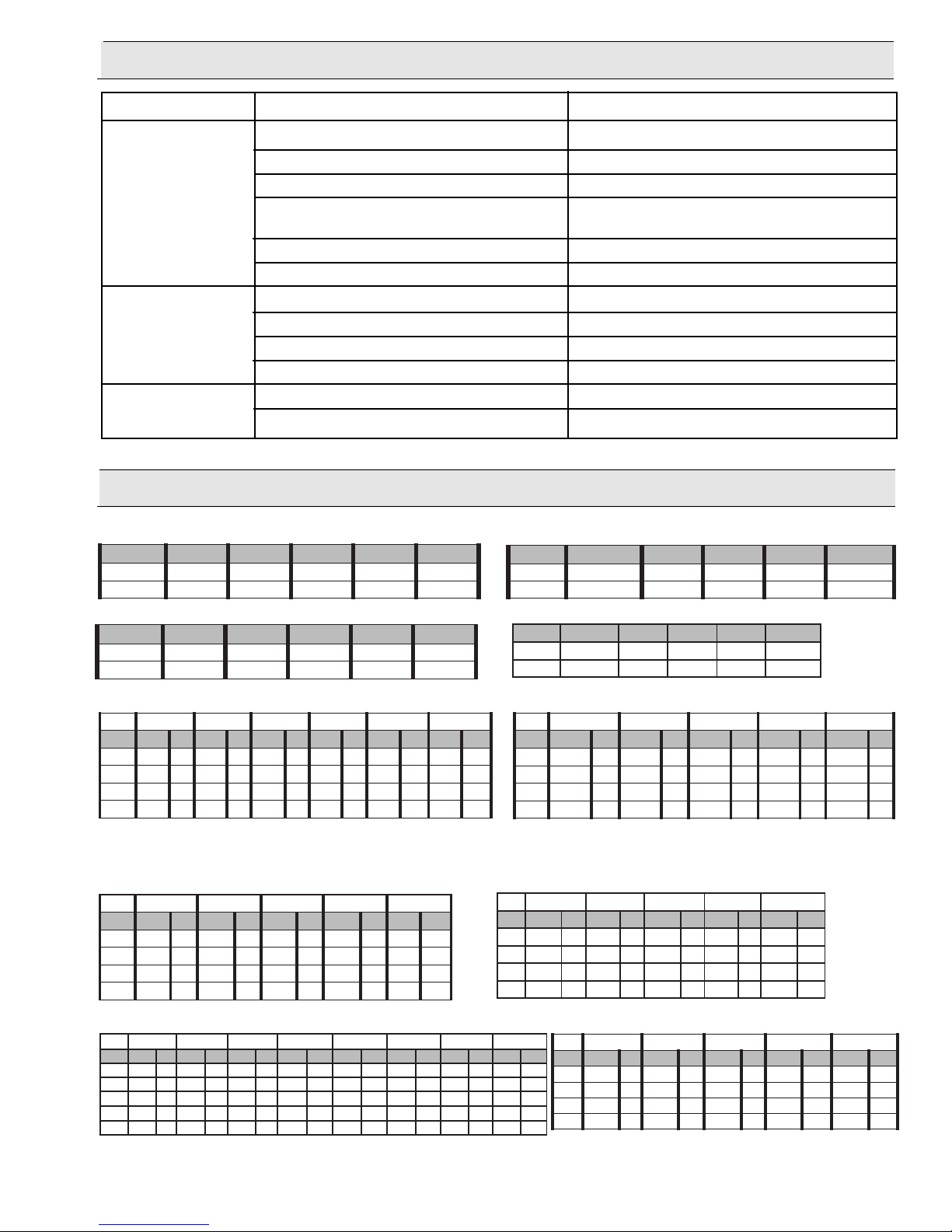
Troubleshooting
erusserP )aPK4.986( aPK0002 aPK0004 aPK0005 )aPK4986(
MP
Rw
m/Iwm/Iwm/Iwm/Iwm/I
00138925.81943.86570.88889.781117.
7
RAB7RAB02RAB04RAB05RAB96
MPR .nim/L W .nim/L W .nim/L W .nim/L W .nim/L W
0092.45612.41622.49932.41641.4575
00218.54226.57535.56355.53064.5937
05419.69628.69937.61067.60076.6888
52712.81231.89540.82960.85189.7950
1
isp001isp002isp003isp004isp005isp006isp007isp008
MPR MPG PH MPG PH MPG PH MPG PH MPG PH MPG PH MPG PH MPG PH
00669.21.49.91.49.62.59.33.49.93.39.54.39.25.39.85.
00915.191.94.103.84.114.74.105.74.106.64.196.64.187.54.178.
002100.282.89.114.79.155.69.176.69.118.59.139.49.160.139.161.1
054124.243.04.205.83.276.73.238.63.279.53.231.133.272.123.224.1
527109.204.98.295.78.208.58.200.138.291.118.283.108.245.197.296.1
Symptom Probable Cause(s) Corrective Action(s)
No Flow or Low Flow. Pump not primed. Refer to Priming in the Operation Section.
Air leaks in suction line. Check and reseal inlet fittings.
Blocked or clogged line strainer. Inspect strainer and clear any debris from screen.
Undersize suction line or collapsed hose. Suction line should be the same diameter as inlet
port of Pump or larger.
Nozzle clogged.
Clear nozzle or replace.
Unloader or Relief Valve not functioning properly. Repair or replace Relief Valve.
w pressure. Debris in Valves. Remove debris. See Repair section.
Lo
Valves worn. Replace Valves. See Repair section.
Unloader or Relief Valve not functioning properly. Repair or replace relief valve.
Pump not primed. See priming in Operation section.
Pump Leaking. Seals worn. Replace Seals. See Repair section.
Body cracked. Replace Body. See Repair section.
Performance Data
Series 53702
erussserP isp001 isp003 isp005 isp007 isp0001
MPRPHMPGPHMPGPHMPGPHMPGPHMPG
05434.2.27.2.29.1.22.11.25.10.2
Series 53703
erussserP isp001 isp003 isp005 isp007 isp0001
MPRPHMPGPHMPGPHMPGPHMPGPHMPG
00134.3.27.2.29.1.22.11.25.10.2
Series 5300C-X
isp05isp001isp002isp003isp004isp005
MPR MPG PH MPG PH MPG PH MPG PH MPG PH MPG PH
527165.121.25.151.05.182.74.153.54.134.44.165.
527122.212.81.282.61.234.21.275.11.217.01.238.
527165.252.45.273.25.225.05.286.84.228.44.269.
527120.373.10.394.00.347.89.229.69.211.149.232.1
TE: Above performance figures based on constant speed
NO
dynamometer tests, pumping water at one foot (approx.) suction lift with
no pulsation damper. Performance will vary with application.
Series 5321C and 5322C
isp001isp003isp005isp007isp0001
MPR MPG PH MPG PH MPG PH MPG PH MPG PH
0091.12.1.14.1.15.1.16.1.18.
00215.13.5.15.5.16.5.18.4.10.1
05418.14.8.16.8.17.8.19.8.12.1
52712.24.1.27.1.28.1.21.11.24.1
erusserP )aPK4.986( aPK0002 aPK0004 aPK0005 )aPK4986(
MPRwm/Iwm/Iwm/Iwm/Iwm/I
05438925.81943.86579.78887.781114.7
RAB7RAB41RAB12RAB5.72RAB5.43
MPR .nim/L W .nim/L W .nim/L W .nim/L W .nim/L W
52718.50017.50026.50035.50035.5004
52713.80022.80030.80040.80050.8006
52716.90035.90045.90054.90062.9007
52714.110044.110063.110072.110081.11009
Series 5324C
RAB7RAB12RAB5.43RAB84RAB55
MPR .nim/L W .nim/L W .nim/L W .nim/L W .nim/L W
0097.50027.50037.50057.50067.5007
00216.70026.70056.70062.70082.7009
05411.90031.90051.90087.800017.80011
52710.110030.110066.010096.0100216.010031
-11-
Page 12
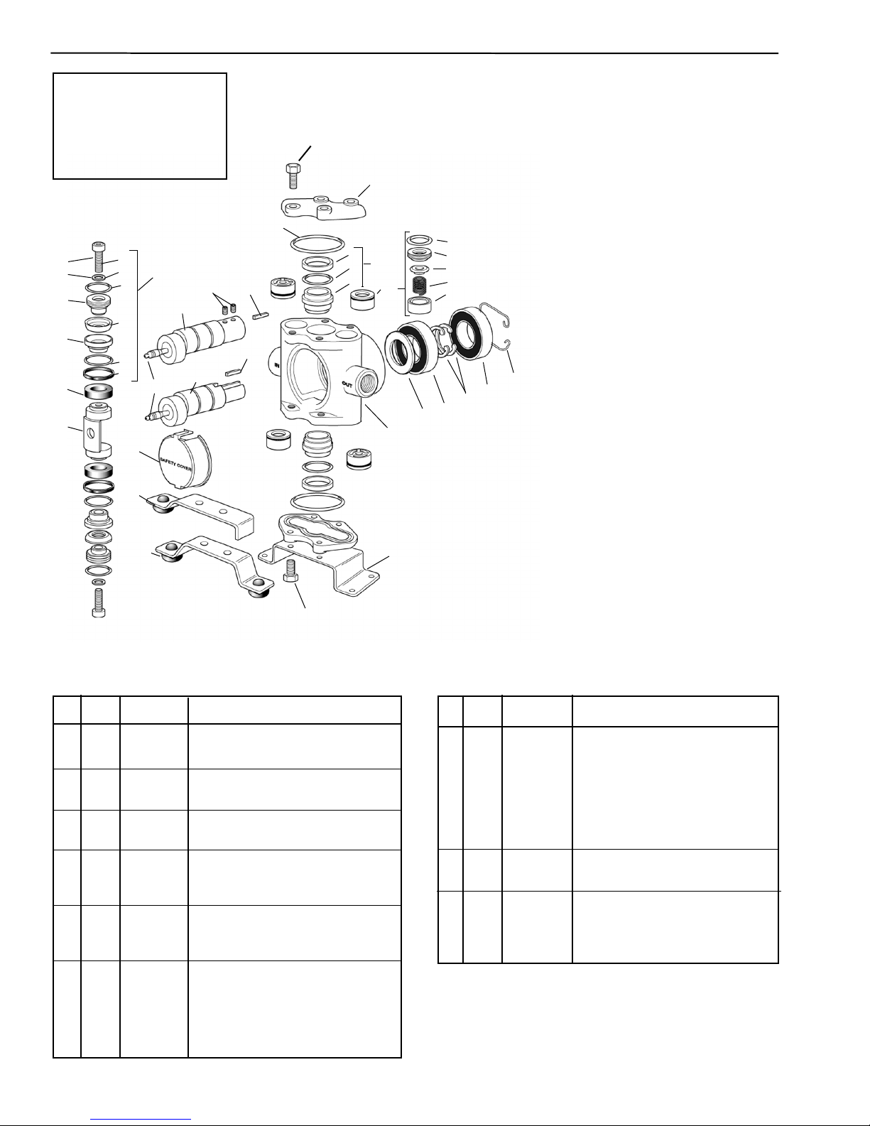
Models 5315C-X,
5320C-X, 5325C-X and 5330C-X
NOTE: When ordering parts,
give QUANTITY, PART NUMBER,
DESCRIPTION, and COMPLETE MODEL NUMBER.
Reference numbers are used
ONLY to identify parts in the
drawing and are NOT to be
used as or
2
3
4
der numbers.
6A
6B
6
6C
13
12
6D
5
6E
6F
7
10
15
8
9
29
30
16
14
19
17
17
Piston Stack Parts Kit
Leather Cup Kit No.
Consists of tw
2220-0012 Piston Cap Screw (Ref. 6A), No. 2270-
Washer (Ref. 6B), No. 1720-0029 O-ring (Ref.
0011
. 2150-0002 Leather Cup (Ref. 6D), No.
6C), No
18
24
25
A
B
C
D
E
25
26
A
20
B
C
21
22
28
1720-0039 O-Ring (Ref. 6E), and No. 1440-0008
Seal Ring (Ref
Rubber Cup Kit No.
Same as above kit except with No. 2150-0005
ber Cups.
Rub
Piston Stac
Leather Cup and Guide Kit No.
Consists of Leather Cup Kit No. 3430-0007 plus two
. 1440-0004 Piston Guides (Ref. 7).
No
Rubber Cup and Guide Kit No.
Consists of Rub
No. 1440-0004 Piston Guides.
eflon Cup and Guide Kit No. 3430-0046
T
Consists of
Guides.
Crankshaft Assemblies
27
Sub-Assemblies include Shaft (Ref. 12 or 15) with
Cam Bear
Set Scre
(Ref. 14 or 16).
Complete Assemblies include the Sub-Assembly
plus par
Sub-Assembly Complete Assembly Pump
Part No. Part No. Model
with 5/8" (I.D.) Hollow Shaft (Ref. 12)
5501-5315
5501-5320 5500-5320
5501-5325 5500-5325 5325C-H
5501-5330 5500-5330 5330C-H
with 5/8" Solid Shaft (Ref. 15)
5001-5315 5000-5315 5315C
5001-5320 5000-5320 5320C
5001-5325 5000-5325 5325C
5001-5330 5000-5330 5330C
ing, Grease Fitting Assembly (Ref. 10),
ws for Hollow Shaft (Ref. 13) and Spline Key
ts identified by Reference Numbers 24-26.
3430-0007
o each of the following parts: No.
. 6F).
3430-0009
k and Guide Parts Kits
3430-0008
3430-0010
ber Cup Kit No. 3430-0009 plus two
Teflon Cup Stack Kit plus 2 Piston
5500-5315 5315C-H
5320C-H
Ref. Qty. Part
No. Req'd. No. Description
2220-0012
2
2
Piston Cap Scre
w
3 2 2270-0011 Washer
4 2 1830-0017 Piston Cup Spreader
2 1410-0030 Cup Backing Plate
5
1
6
Piston Stack Parts Kit (see listing above)
7 2 1440-0004 Piston Guide
8 1 0502-5300 Connecting Rod
9 1 0608-5300 Safety Cover
1 2405-0006 Grease Fitting Assembly
10
12
ankshaft Assemb
1
Cr
lies — Hollow Shaft
Models, see listing above
13 2 2230-0017 Set Screw for Hollow Shaft
14 1 1610-0011 Spline Key for Hollow Shaft
15 1 Crankshaft Assemblies — Solid Shaft
, see listing abo
Models
16 1 1610-0007 Spline Key for Solid Shaft
17 8 2210-0062 Cylinder Head Bolt
2 0204-5300C Cylinder Head (Cast Iron)
18
19 2 1720-0038 O-ring for Cylinder Head
20 1 3430-0209 Ni-Resist Cylinder Sleeve Assembly
Consists of two each of No. 1830-0033
Retainer (Ref. A), No. 1720-0079
O-ring (Ref. V), and No. 3550-0018
C)
.
e (Ref
v
Slee
Ref. Qty. Part
No. Description
Req'd.
No.
21 1 set 3430-0197 Set of four No. 3400-0073 Unitized
Valve Assemblies: Consists of four
O-ring (Ref. A), Valve Seat (Ref.
each:
B), Valve Poppet (Ref. C), Valve
Spring (Ref. D), Valve Spring Retainer
(Ref. E)
22 1 0108-5300C Body (Cast Iron)
24
1
2130-0007
Bearing Shield
25 2 2008-0001 Main Bearing (Ball Bearing)
26 2 1810-0013 Bearing Retainer Ring (shaft)
27 1 1820-0025 Bearing Retainer Ring (housing)
1510-0056 Mounting Base
1
28
29 1 2820-0040 Torque Arm — for Electric Motor
Mounting
e
v
30 1 2820-0042 Torque Arm — for Gas Engine
Mounting
-12-
Page 13
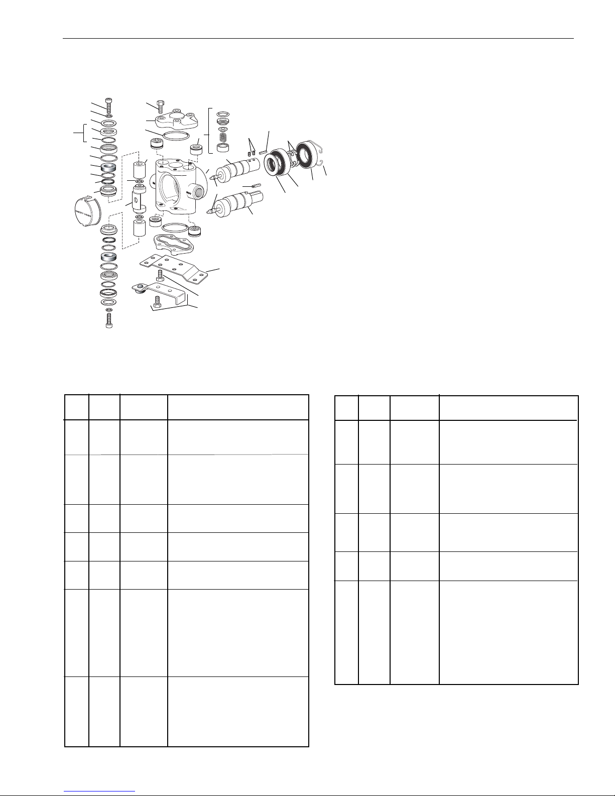
Models 5321C and 5322C
Plunger Parts Kits
Plunger Stack Parts Kit No. 3430-0144 (Model 5321)
Consists of tw
. 1440-0037 Guides, No. 1720-0064 O-rings, No. 1720-0079 O-rings,
No
No. 2150-0027 Seal Assemblies, No. 2220-0039 Socket Head Cap
2
3
4
A
5
B
6
7
8
9
10
11
34
15
16
17
12
18
19
A
B
C
D
24
25
30
E
22
21
27
28
29
29
13
26
32
15A
33
Scre
Plunger Parts Kit No. 3430-0145 (Model 5321)
Consists of one No
3500-0021 Plungers
Plunger Stack Parts Kit No. 3430-0291 (Model 5322)
Consists of tw
No. 1440-0037 Guides, No. 1720-0064 O-rings, No. 1720-0079 O-rings,
. 2150-0027 Seal Assemblies, No. 2220-0039 Socket Head Cap
No
Screws, and No. 2270-0042 Washers.
31
Plunger Parts Kit No. 3430-0292 (Model 5322)
Consists of one No
3500-0036 Plungers.
Crankshaft Assemblies
Solid Shaft Sub-Assemb
Consists of one each of the f
No. 1600-0014 Crankpin Retainer, No. 2007-0029 Cam Bearing, No.
2405-0006 Grease Fitting Assemb
Solid Shaft Assembly No. 5000-5321
Consists of one No. 5001-5321 Crankshaft Sub-Assembly, two No.
1810-0013 Retaining Rings
No. 2130-0007 Bearing Shield.
Hollow Shaft Sub-Assembly No. 5501-5321
Consists of one No. 0550-5321 Crankshaft, one No. 2007-0029 Cam
Bear
0011 K
Hollow Shaft Assembly No. 5500-5321
Consists of one No. 5501-5321 Crankshaft Sub-Assembly, two No.
1810-0013 Retaining Rings, two No. 2008-0001 Main Bearings, and one
No. 2130-0007 Bearing Shield.
o each of the following parts: No. 1440-0010 Seal Rings,
ws, and No. 2270-0042 Washers.
. 3430-0144 Plunger Stack Parts Kit and two No.
.
o each of the following parts: No. 1440-0010 Seal Rings,
. 3430-0291 Plunger Stack Parts Kit and two No.
ly No. 5001-5321
wing parts: No. 0500-5321 Crankshaft,
ollo
ly, and No. 1610-0007 Key.
, two No. 2008-0001 Main Bearings, and one
ing, one No. 2405-0006 Grease Fitting Assembly, one No. 1610-
ey, and two No. 2230-0017 Set Screws.
Ref. Qty.Part
No. Req'd. No. Description
2 2 2220-0039 Socket Head Cap Screw
3 2 2270-0042 Washer
4 2 1830-0056 Retainer
5 2 2150-0027 Seal Assembly: Consists of No.
2150-0049 Seal (Ref. A) and No.
B)
1440-0061 Suppor
t Ring (Ref
.
6 2 1830-0054 Seal Retainer
7 2 1720-0079 O-ring for Seal Retainer
1440-0037
8
2
Guide
9 2 1720-0064 O-ring for Seal Ring
10 2 1440-0010 Seal Ring
11 2 1830-0053 Guide Retainer
12
2 3500-0021 Plunger (steel, Model 5321)
12 2 3500-0036 Plunger (ceramic, Model 5322)
13
1
0502-5300
Connecting Rod (Model 5321)
13 1 0504-5300 Connecting Rod (Model 5322)
14 1 0608-5300 Safety Cover
15
*
2210-0063
Cylinder Head Bolt (8 bolts required
for Model 5321C-H Hollow Shaft
op
T
4 bolts required f
Pump;
or
Cylinder Head ONLY on Solid Shaft
Pumps)
15A
4
2210-0064
Extra Long Cylinder Head Bolt for
securing mounting base to Solid
Shaft Models
16 2 0201-5300C Cylinder Head (Cast Iron)
1720-0038 O-ring for Cylinder Head
17
2
18 1 set 3430-0197 Set of four No. 3400-0073 Unitized
Valve Assemblies: Consists of four
each: O-ring (Ref. A), Valve Seat (Ref.
Valve Poppet (Ref. C), Valve
B),
Spr
ing (Ref
D), and
.
alve Spring
V
Retainer (Ref. E)
Ref. Qty. Part
No. Req'd. No. Description
19 1 0108-5300C Body (Cast Iron)
21 1 2405-0006 Grease Fitting
22
1
Hollow Shaft Sub-Assembly (see
listing above)
24
2 2230-0017 Set Screws for Hollow Shaft
25 1 1610-0011 Spline Key for Hollow Shaft
26
27
1
1
1610-0007
Solid Shaft Sub-Assembly (see listing
ve)
abo
or Solid Shaft
y f
e
Spline K
28 1 2130-0007 Shield
29 2 2008-0001 Main Bearing
30 2 1810-0013 Retaining Ring (shaft)
31 1 1820-0025 Retaining Ring (housing)
32 1 1510-0041 Mounting Base for Solid Shaft Models
33 1 3420-0030 Torque Arm Kit for Hollow Shaft
Models - Consists of No. 2820-0035
1450-0003 Bumper
.
orque Ar
T
m, No
and two No. 2210-0064 Bolts
34 2 2270-0097 Washer (Model 5322 only)
-13-
Page 14
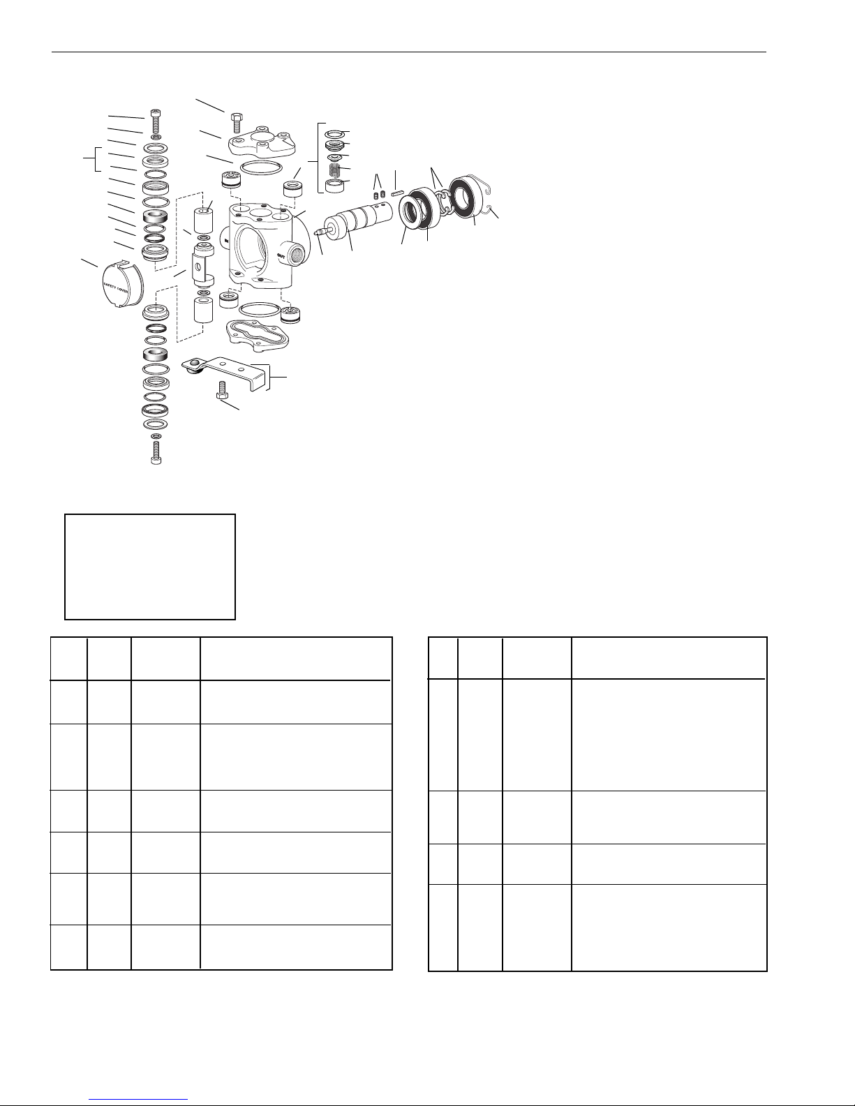
15
2
3
16
4
A
5
B
17
6
7
8
9
10
12
34
11
14
13
NOTE: When ordering parts,
give QUANTITY, PART NUMBER, DESCRIPTION, and COMPLETE MODEL NUMBER.
Reference numbers are used
ONLY to identify parts in the
drawing and are NOT to be
used as order numbers.
15A
Spec Pumps 53702 and 53703
A
B
18
C
24
D
25
30
E
19
29
21
22
28
33
Plunger Parts Kits
Plunger Stack Parts Kit No. 3430-0291
Consists of two each of the follo
No. 1440-0010-6 Seal Rings, No. 1440-0037
Guides, No. 1720-0064 O-rings, No. 1720-0079
O-rings, No. 2150-0027 Seal Assemblies, No.
2220-0039 Soc
No. 2270-0042 Washers, and No. 2270-0051
Washers.
Plunger Parts Kit No. 3430-0292
Consists of one No. 3430-0291 Plunger Stack
Parts Kit and two No. 3500-0036 Plungers.
ket Head Cap Screws,
31
29
wing parts:
Crankshaft Assemblies
Spec Pump No.
Hollow Shaft Sub-Assembly No. 5501-5318
Consists of one No
2007-0029 Cam Bearing, one No. 2405-0006
Grease Fitting Assemb
o No. 2230-0017 Set Screws.
tw
Hollow Shaft Assembly No. 5500-5318
Consists of one No
ly, two No. 1810-0013 Retaining Rings, two
Assemb
No. 2008-0001 Main Bearings, one No. 2130-0007
ing Shield.
Bear
Spec Pump No. 53703
Hollow Shaft Sub-Assembly No. 5501-5320
Consists of one No
2007-0029 Cam Bear
Grease Fitting Assembly, one No. 1610-0011 Key,
o No. 2230-0017 Set Screws.
tw
Hollow Shaft Assembly No. 5500-5320
Consists of one No. 5501-5320 Crankshaft Sub-
ly, two No. 1810-0013 Retaining Rings, two
Assemb
No. 2008-0001 Main Bearings, one No. 2130-0007
Bearing Shield.
53702
. 0550-5318 Crankshaft, one No.
ly, one No. 1610-0011 Key,
. 5501-5318 Crankshaft Sub-
. 0551-5320 Crankshaft, one No.
ing, one No. 2405-0006
.Part
Qty
.
Ref
Req'd. No. Description
No.
2 2 2220-0039 Socket Head Cap Screw
3 2 2270-0042 Washer
4 2 1830-0056 Retainer
5 2 2150-0027 Seal Assembly: Consists of one No.
2150-0049,
Seal (Ref
A) and one No
.
. 1440-0061
Support Ring (Ref. B)
1830-0054
6
2
Seal Retainer
7 2 1720-0079 O-ring for Seal Retainer
8 2 1440-0037 Guide
ing for Seal Ring
1720-0064
9
2
O-r
10 2 1440-0010 Seal Ring
11 2 1830-0053 Guide Retainer
3500-0036 Plunger
12
2
13 1 0504-5300 Connecting Rod
14 1 0608-5300 Safety Cover
15 8 2210-0063 Cylinder Head Bolt
15A 2 2210-0064 Extra Long Cylinder Head Bolt for
torque arm
16
2
0201-5300C
Cylinder Head (Cast Iron)
17 2 1720-0038 O-ring for Cylinder Head
.Part
Qty
.
Ref
Req'd. No. Description
No.
18 1 Set 3430-0197 Set of four No. 3400-0073
Unitized Valve Assemblies:
Consists of f
our each: O-ring (Ref. A),
Valve Seat (Ref. B), Valve Poppet
. D), Valve
ing (Ref
e Spr
alv
V
C),
.
(Ref
Spring Retainer (Ref. E)
19 1 0108-5300C Body (Cast Iron)
2405-0006 Grease Fitting
21
1
22 1 **** Hollow Shaft Sub-Assembly (See
listing above for description)
24 2 2230-0017 Set Screws for Hollow Shaft
25
1 1610-0011 Spline Key for Hollow Shaft
28 1 2130-0007 Shield
29
2
2008-0001
Main Bear
ing
30 2 1810-0013 Retaining Ring (shaft)
31 1 1820-0025 Retaining Ring (housing)
3420-0030 Torque Arm Kit: Includes (1) No.
33
1
2820-0035 Torque Arm, (1) No.
1450-0003 Bumper and (2) No
.
2210-0064 Bolts.
34 2 2270-0097 Washer
-14-
Page 15
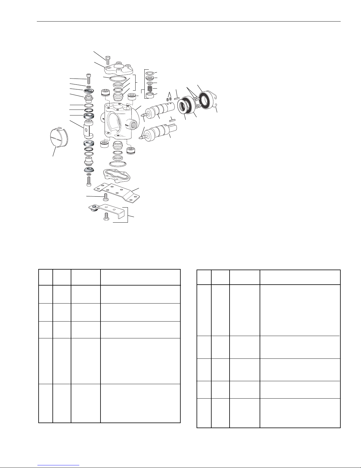
Models 5324C and 5324C-H
10
11
12
16
18
A
B
C
D
E
19
21
24
22
27
25
26
28
26
2
13
3
4
5
A
14
B
C
15
6
7
8
9
23
Piston Parts Kit
Piston Stack Parts Kit No. 3430-0191
Consists of two each of the following parts: No. 22200012 Cap Scre
(Ref. 3), No. 2150-0047 Cup (Ref. 4), No. 1720-0029
ing (Ref. 6), No. 1440-0059 Seal Ring (Ref. 7) and
O-r
. 1440-0060 Guide (Ref. 8).
No
w (Ref. 2), No. 2270-0011 Washer
Crankshaft Assembly Kits
Model 5324C
Solid Shaft Sub-Assembly No. 5001-5321
Consists of one each of the following parts: No.
0500-5321 Crankshaft, No. 1600-0014 Crankpin
, No. 2007-0029 Cam Bearing, No. 2405-
Retainer
0006 Grease Fitting Assembly, No. 1610-0007 Key.
Solid Shaft Assemb
Consists of one No
ly, two No. 1810-0013 Retaining Rings, two
Assemb
No. 2008-0001 Main Bearings, one No. 2130-0007
ing Shield.
Bear
ly No. 5000-5321
. 5001-5321 Crankshaft Sub-
Model 5324C-H
11A
30
29
Hollow Shaft Sub-Assembly No. 5501-5321
Consists of one No
1600-0014 Crankpin Retainer, one No. 2007-0029
Cam Bearing, one No. 2405-0006 Grease Fitting
ly, one No. 1610-0011 Key, two No. 2230-
Assemb
0017 Set Screws.
Hollow Shaft Assembly No. 5500-5321
Consists of one No
Assembly, two No. 1810-0013 Retaining Rings, two
No. 2008-0001 Main Bearings, one No. 2130-0007
Bearing Shield.
. 0550-5321 Crankshaft, one No.
. 5501-5321 Crankshaft Sub-
Ref. Qty. Part
No.
2
Req'd.
No. Description
2220-0012
2
Piston Cap Scre
w
3 2 2270-0011 Washer
4 2 2150-0047 Cup
1830-0092 Cup Holder
5
2
6 2 1720-0029 O-Ring
1440-0059
7
2
Seal Ring
8 2 1440-0060 Guide
9 1 0500-5324 Connecting Rod
ety Cover
10
1
0608-5300
Saf
11 * 2210-0063 Cylinder Head Bolt (8 required for
Hollow Shaft Pump; 4 required for
top cylinder head ONL
Y on Solid
Shaft Pump)
11A 4 2210-0064 Extra Long Cylinder Head Bolt for
securing mounting base to Solid
Shaft Pump
12 2 0201-5300C Cylinder Head (Cast-Iron)
13
2
1720-0038
O-Ring
14 1 3430-0210 Ni-Resist Cylinder Sleeve Assembly:
Consists of two each of No.
1830-0033 Retainer (Ref. A), No.
1720-0079 O-ring (Ref. B), and No.
C)
.
e (Ref
3550-0028 Slee
v
Qty. Part
.
Ref
No. Req'd. No. Description
15 1 set 3430-0197 Set of four No. 3400-0073 Unitized
Valve Assemblies: Consists of four
A), Valve Seat
.
ing (Ref
O-r
each:
(Ref. B), Valve Poppet (Ref. C),
Valve Spring (Ref. D), Valve Spring
Retainer (Ref. E)
16
1
0108-5300C
Body (Cast Iron)
18 1 2405-0006 Grease Fitting
19 1 Hollow Shaft Sub-Assembly (see
listing above)
21 2 2230-0017 Set Screw for Hollow Shaft Pump
or Hollow Shaft Pump
y f
e
22
1
1610-0011
K
23 1 Solid Shaft Sub-Assembly (see list-
ing above)
1610-0007 Key for Solid Shaft Pump
24
1
25 1 2130-0007 Shield
26 2 2008-0001 Bearing
27 2 1810-0013 Retaining Ring (shaft)
28
1 1820-0025 Retaining Ring (housing)
29 1 1510-0041 Mounting Base for Solid Shaft Pump
or Hollow Shaft
30
1
3420-0030
orque Ar
T
m Kit f
Pump: Consists of (1) No. 2820-0035
T
orque Arm, (1) No. 1450-0003
Bumper and (2)No
2210-0064 Bolts
.
-15-
Page 16
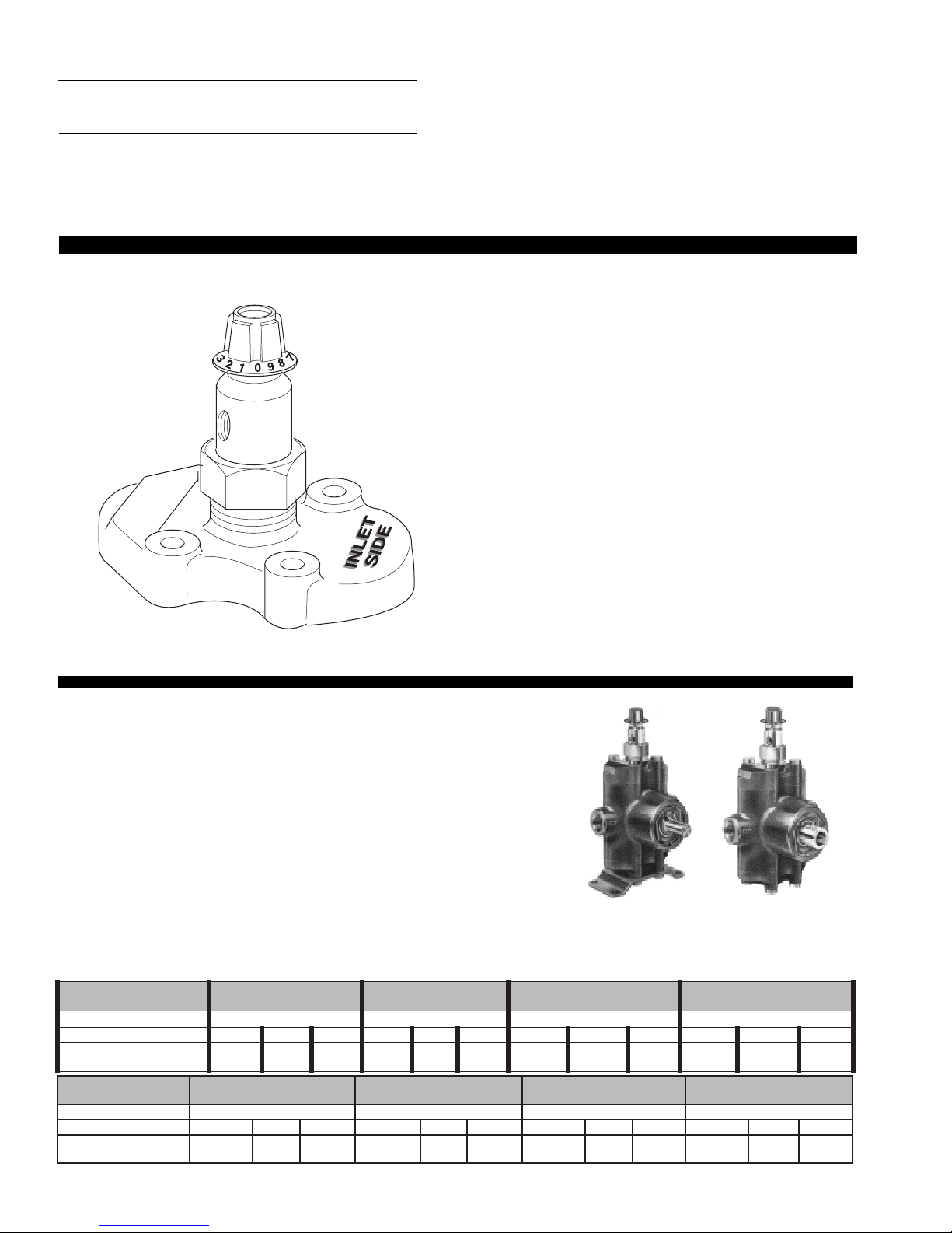
Accessory
PMUPNOTSIPORPYH
0235LEDOM
).nim/L75.7(
0335LEDOM
).nim/L4.11(
1235LEDOM
).nim/L3.8(
4235LEDOM
).nim/L11(
teltuOpmuPtaerusserP aPM54.3aPM54.3aPM9.6aPM25.5
snoitidnoCtelnIpmuP gH/mm721aPk9.86aPk8.731gH/mm721aPk9.86aPk8.731gH/mm721aPk9.86aPk8.731gH/mm721aPk9.86aPk8.731
detcejnIretaWmumixaM
etuniMreP
lm4.662lm6.771lm841lm4.662lm6.771lm841lm4.662lm6.771lm841lm4.662.lm6.771lm841
HYPRO SERIES
Liquid Injector Heads
Model 3396-0014
for Hypro Series 5300 cast iron pumps with suffix "X"
Model 3396-0006
for Hypro Series 5321 and 5324 cast iron pumps
SPECIFICATIONS
Cylinder Head — Cast iron with special flow
Inlet Port — 1/8" NPT (F) can be positioned to face any
direction.
Brass Valve Stem — Needle-type metering, for accurate
mixing of injected solution and liquid being pumped.
Unitized Valve Assembly — Stainless steel valve
spring, ball and valve seat. Nylon spring retainer.
Control Knob — Calibrated with 9 steps in a 360o turn.
Can be rotated up to three times.
Maximum Temperature — 140o Fahrenheit (60oC)
Net Weight — Model 3396-0014: 1 lb. 8 oz. (594.8 g.)
3396-0006
3396-0014
Model 3396-0006: 1 lb. 12 oz. (793.2 g.)
The Hypro Series 3396 Liquid Injector Head mounts directly on the pump,
replacing the regular cylinder head.
mixing it with the regular pump flo
disassemb
Amount of solution injected is regulated by a needle valve and adjusted by a
calibrated control knob. Positive seating ball-type check valve prevents back
w of liquid from the pump into the injector
flo
detergent and other solutions through the injector
supply, followed by a clear water rinse through the pump.
The 1/8" NPT (F) inlet por
w regulator channel in the cylinder head compensates f
flo
mercury (127 mm/Hg), up to a maximum incoming pressure of 20 psi (137.8
kPa). NOTE: If incoming pressure is higher, a pressure regulator must be
used.
led to install the injector
t can be positioned to f
PMUPNOTSIPORPYH
teltuOpmuPtaerusserP isp005isp005isp0001isp008
snoitidnoCtelnIpmuP gH''5isp01isp02gH''5isp01isp02gH''5isp01isp02gH''5isp01isp02
detcejnIretaWmumixaM
etuniMreP
.zo9.zo6.zo5.zo01.zo9.zo8.zo2/1-11.zo2/1-01.zo8.zo71.zo2/1-51.zo31
It feeds solution directly into the pump,
No inter
.
w
.
0235LEDOM
)MPG2(
nal pump par
This allo
.
, then b
ace an
ed or
ts are remo
ws application of soap
y closing the injector
y direction.
or various inches of
)MPG3(
v
uilt-in
A b
0335LEDOM
-16-
,
Series 5300 Pump
with Model 3396-0014
Liquid Injector Head
Add suffix letter "D" to pump model number
1235LEDOM
)MPG2.2(
Series 5321 Pump
with Model 3396-0006
Liquid Injector Head
4235LEDOM
)MPG9.2(
Page 17
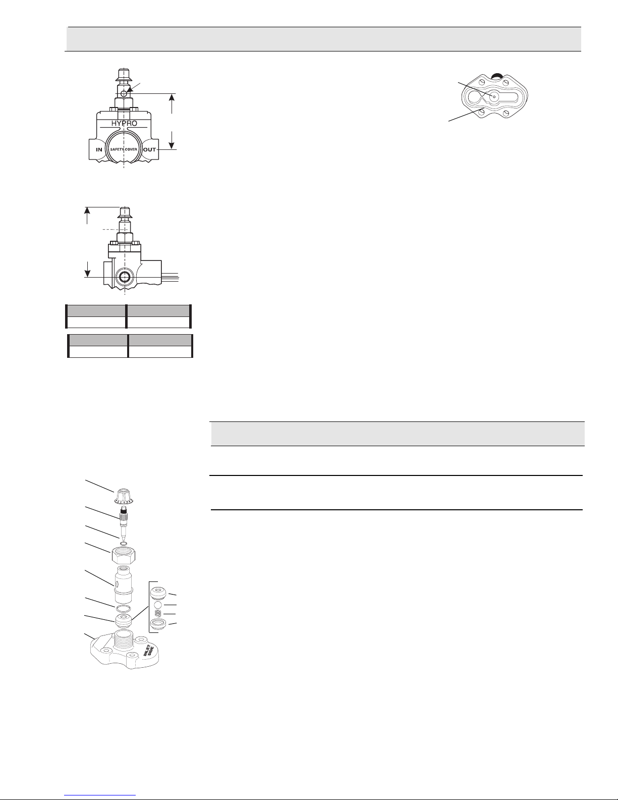
DIMENSIONS INSTALLATION: IMPORTANT
Liquid injector cylinder head MUST
1/8-27 NPT
be installed with the flow regulator
channel o
ver the inlet valve of the
Flow
Regulator
Channel
pump. "Inlet Side” is cast on the
cylinder head of injector for ease in
X
identification.
O-ring
Groove
TO ADJUST THE POSITION OF THE INLET PORT
o change the position of the liquid injector inlet port, loosen the retainer nut (Ref.
T
5), and rotate injector body (Ref. 4) until the opening is in the desired position. It is
important that the retainer nut be fully tightened to properly compress the o-ring
seal (Ref
Y
OPERATION
Before using the injector, make sure the retainer nut is tightened securely. NOTE:
The “Inlet Port” on the body indicates the position of the dial setting (closed position
is zero). The larger the number, the more flow is allowed. DO NOT rotate the control knob more than three complete turns.
''61/31-3=X ''61/5-5=Y
mm8.69=Xmm531=Y
''61/3-3=X ''61/11-5=Y
mm4.601=Xmm5.441=Y
MAINTENANCE
If opening around needle valve stem becomes clogged, clean the valve stem and
passage way with warm soapy water. Rotate the control knob assembly counterclockwise (which includes the control knob and needle valve stem) until it can be
lifted out of the body. Inspect the valve stem o-ring and replace if necessary.
Install the control knob assembly by pushing down firmly on the knob and turning
clockwise until it is in the closed position. Set the injector to the desired setting.
. 3) against the valve assembly (Ref. 2)
PARTS LIST
Model No. 3396-0014, 3396-0006 Liquid Injector Heads
8
7
6
5
4
3
2
1
A
B
C
D
Ref. Quantity Part
No.
1
Required
1 0257-5300C Cylinder Head for Model 3396-0014 (cast iron)
Number Description
1 1 0254-5300C Cylinder Head f
2 1 3400-0098 Unitiz
ed
e Assemb
alv
V
3 1 1720-0029 O-ring
4 1 3200-0027 Body
5 1 3240-0006 Retainer Nut
6 1 1720-0033 O-ring
7 1 3220-0016 Needle
8 1 2802-0002 Calibr
Valve Stem
ated Adjustment Control Knob
or Model 3396-0006 (cast iron)
ly
-17-
Page 18

NOTES
-18-
Page 19

NOTES
-19-
Page 20

Limited Warranty on Hypro Pumps and Other Hypro Products
Hypro warrants to the original purchaser of its products (the “Purchaser”) that such products will be free from defects
in material and workmanship under normal use for the period of one (1) year for all products except: oil crankcase
plunger pumps will be free from defects in material and workmanship under normal use for the period of five (5)
years, and accessories will be free from defects in material and workmanship under normal use for the period of
ninety (90) da
defects in material and workmanship under normal use and from damage resulting from environmental conditions for
the life of the pump.
mal use” does not include use in excess of recommended maximum speeds, pressures, vacuums and tempera-
“Nor
tures, or use requiring handling of fluids not compatible with component materials, as noted in Hypro product catalogs, technical literature, and instructions. This warranty does not cover freight damage, freezing damage, normal
wear and tear, or damage caused by misapplication, fault, negligence, alterations, or repair that affects the performance or reliability of the product.
THIS WARRANTY IS EXCLUSIVE. HYPRO MAKES NO OTHER WARRANTY, EXPRESS OR IMPLIED, INCLUDING BUT NOT LIMITED TO ANY WARRANTY OF MERCHANTABILITY OR FITNESS FOR A PARTICULAR PURPOSE.
Hypro’s obligation under this warranty is, at Hypro’s option, to either repair or replace the product upon return of the
entire product to the Hypro factory in accordance with the return procedures set forth below. THIS IS THE EXCLU-
SIVE REMEDY FOR ANY BREACH OF WARRANTY.
IN NO EVENT SHALL HYPRO BE LIABLE FOR ANY INCIDENTAL OR CONSEQUENTIAL DAMAGES OF ANY
KIND, WHETHER FOR BREACH OF ANY WARRANTY, FOR NEGLIGENCE, ON THE BASIS OF STRICT LIABILITY, OR OTHERWISE.
ys. In addition, Hypro warrants to the purchaser all forged brass pump manifolds will be free from
Return Procedures
All pumps or products must be flushed of any chemical (ref. OSHA Section 0910.1200 (d)(e)(f)(g)(h)) and hazardous chemicals must be labeled before being shipped* to Hypro for service or warranty consideration.
Hypro reserves the right to request a Material Safety Data sheet from the Purchaser for any pump or product Hypro
deems necessary. Hypro reserves the right to “disposition as scrap” pumps or products returned which contain
unknown substances, or to charge for any and all costs incurred for chemical testing and proper disposal of components containing unknown substances. Hypro requests this in order to protect the environment and personnel from
the hazards of handling unknown substances.
For technical or application assistance, call the
To obtain service or warranty assistance, call the Hypro Service and Warranty number: 1-800-468-3428;
or call the Hypro Service and Warranty FAX: (651) 766-6618.
Be prepared to give Hypro full details of the problem, including the following information:
1. Model number and the date and from whom you purchased your pump.
2.
Hypro may request additional information, and may require a sketch to illustrate the problem.
Contact the factory to receive a return material authorization before sending the product. All pumps returned for warranty work should be sent shipping charges prepaid to: HYPRO
ief descr
A br
• Liquid pumped. State the pH and any non-soluble • Drive type (gas engine/electric motor; direct/belt drive;
materials, and give the generic or trade name. tractor PTO) and rpm of pump.
• Temperature of the liquid and ambient environment. • Viscosity (of oil, or other than water weight liquid).
• Suction lift or vacuum (measured at the pump). • Elevation from the pump to the discharge point.
• Discharge pressure. • Size and material of suction and discharge line.
• Size, type, and mesh of the suction strainer. • Type of spray gun, orifice size, unloader/relief valve.
iption of the pump problem, including the following:
Hypro Technical/Application number: 1-800-445-8360.
Attention: Service Department
375 Fifth Avenue NW
New Brighton, Minnesota 55112-3288
Printed in the USA
2005 Hypro
 Loading...