

Hypro 9910-D252GRGI58, 9910-D303, 9910-D252GRGI, 9910-D252GRGIAP, 9910-D303GRGI Installation, Operation, Parts And Service Manual
...Page 1
Medium Pressure
www.contree.com • 920-356-0121 • [email protected]
Diaphragm Pumps
Installation, Operation, Repair, and Parts Manual
Description
California Proposition 65 Warning -- This product
and related accessories contain chemicals known to the
State of California to cause cancer, birth defects or other
reproductive harm.
Hypro medium pressure diaphragm pumps are
recommended for spraying herbicides, pesticides,
liquid fertilizers, and many other hard-to-handle fluids.
Low-cost maintenance and almost wear-free operation
make these pumps ideal for a wide variety of spraying
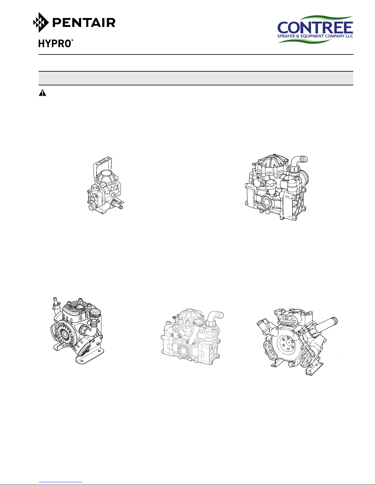
Model 9910-D252
Model 9910-D252GRGI
Model 9910-D252GRGI58
Model 9910-D252GRGIAP
Max flow: 6 gpm
Max pressure: 290 psi
Max speed: 650 rpm (D252)
3600 rpm (D252GRGI)
2 diaphragms
jobs. Pressure and output are designed for optimum
performance of small to medium-sized sprayers.
Hypro medium pressure diaphragm pumps can be
adapted for male 1-3/8” splined shaft, female 1-3/8”
splined shaft, 1” solid shaft, or gear reduction drive
options. See kits on page 2. Pumps include a pulsation
dampener except for Models 9910-D303, D403, and
D503.
Model 9910-D30
Model 9910-D30AP-A
Model 9910-D30GRGI
Model 9910-D30-B-GRGI
Max flow: 9 gpm
Max pressure: 580 psi
Max speed: 550 rpm (D30)
3600 rpm (D30GRGI)
2 diaphragms
Model 9910-D303
Model 9910-D303GRGI
Model 9910-D403
Model 9910-D403GRGI
Max flow: 7.9 gpm (D303)
10.6 gpm (D403)
Max pressure: 580 psi
Max speed: 550 rpm (D303 & D403)
3600 rpm (D303GRGI & D403GRGI)
3 diaphragms
Model 9910-D50
Model 9910-D50AP-A
Model 9910-D50-B
Max flow: 14 gpm
Max pressure: 580 psi
Max speed: 550 rpm
2 diaphragms
See page 2 for drive options and control units.
Model 9910-D503
Model 9910-D503GRGI
Max flow: 15 gpm
Max pressure: 580 psi
Max speed: 550 rpm (D503)
600 rpm (D503GRGI)
3 diaphragms
Page 2
Drive Options:
www.contree.com • 920-356-0121 • [email protected]
2
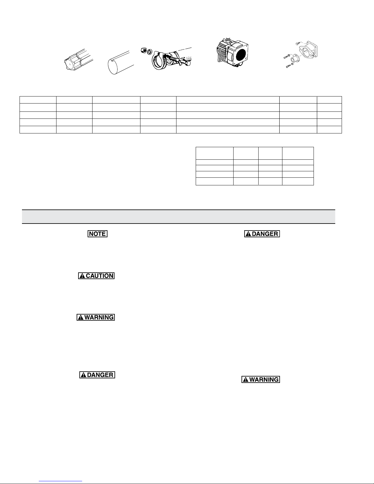
Order the appropriate shaft adapter kit or gear reduction unit for the
drive option requirements. Refer to the adjoining chart for proper
selection. For proper installation, refer to pages 4 through 8.
Gear
Pump
Model
9910-D503 9910-KIT2200 9910-KIT2202 9910-KIT2204 9910-KIT1642 for 8 hp, or 9910-KIT 1640 for 5 hp 9910-HYD5312 8000-0056
9910-D252
9910-D303/403
9910-D30
9910-D50
1-3/8” Male 1-3/8” Female Reduction Hydraulic
Splined PTO 1” Solid Shaft Splined PTO Units for Gas Motor Mounting
Shaft W/Keyway Coupler Engine Drive Flange Kit
N/A 3/4” Solid Shaft. Std. N/A Order gear reduced models N/A
9910-KIT2200 9910-KIT2202 9910-KIT1704 9910-KIT1640 for 5 hp 9910-HYD5312 8000-0056
9910-KIT1702 9910-KIT1703 9910-KIT1704 9910-KIT1640 for 5 hp 9910-HYD5312 8000-0056
9910-KIT1706 9910-KIT1707 9910-KIT1704 9910-KIT1642 for 8 hp, or 9910-KIT 1640 for 5 hp 9910-HYD5312
Hypro
Gearbox
Control Units:
Control units are available for easy flow and pressure control
of your sprayer system. These units include a manual dump
valve and adjustable pressure relief valve to control pressure,
a liquid-filled pressure gauge to monitor pressure, and shut-off
valves to control flow. Control unit GR40 and GS40GI can be
remote mounted with kit no. 9910-KIT1741. Refer to the adjoining chart to select the proper control unit for your pump.
General Safety Information
Notes are used to notify of installation, operation, or
maintenance information that is important but not
safety related.
Caution is used to indicate the presence of a hazard, which will or can cause minor injury or property
damage if the notice is ignored.
Warning denotes that a potential hazard exists and
indicates procedures that must be followed exactly
to either eliminate or reduce the hazard, and to avoid
serious personal injury, or prevent future safety
problems with the product.
Control Max. Max. Pump
Unit Model GPM PSI Model
9910-KIT 1990 6 290 D252
9910-GR40 11 580 D303/D403
9910-GS40GI 21 580 D50 & D30
9910-RM40 24 580 D503
• Do not pump flammable or explosive fluids
such as gasoline, fuel oil, kerosene, etc. Do not
use in explosive atmospheres. Do not pump
asphalt sealer, roofing compounds, concrete
sealers, or any two-step curing products. The
pump should only be used with liquids compatible with the pump materials. Failure to follow
this notice can result in severe personal injury
and/or property damage and will void the product warranty.
• Never use your hand to check the condition
of hydraulic lines or hoses. If hydraulic fluid
penetrates the skin, get medical attention immediately. Failure to get proper medical attention
may result in loss of limb or life. The safest way
to check hydraulic lines is by holding a piece of
cardboard next to the hydraulic line or hose.
Danger is used to indicate the presence of a hazard
that will result in severe personal injury, death, or
property damage if the notice is ignored.
• The sound pressure level of the pump may
exceed 80dBA. Observe all safety precautions
when operating the pump within close proximity
for extended periods by wearing hearing protectors. Extended exposure to elevated sound
levels will result in permanent loss of hearing
acuteness, tinnitus, tiredness, stress, and other
effects such as loss of balance and awareness.
• Verify that pump shaft rotates freely prior to
engaging the pump drive.
Page 3
• Do not pump at pressures higher than the maxi-
www.contree.com • 920-356-0121 • [email protected]
3
mum recommended pressure.
• Check all hoses for weak or worn condition
before each use. Make certain that all connections are tight and secure.
• Operate the pump between a temperature range of
45o to 140o F [7o to 60o C].
• Make certain that the power source conforms to
the requirements of your equipment.
• Provide adequate protection in guarding around
the moving parts such as shafts and pulleys.
• Disconnect the power before servicing.
• Release all pressure within the system before servicing any component.
• Drain all liquids from the system before servicing.
• Secure the discharge line before starting the
pump. An unsecured discharge line may whip,
resulting in personal injury and/or property damage.
Hazardous Substance Alert
• Periodically inspect the pump and the system
components. Perform routine maintenance as
required (see maintenance).
• When wiring an electrically driven pump, follow
all electrical and safety codes, as well as the
most recent National Electrical Code (NEC) and
the Occupational Safety and Health Act (OSHA)
requirements.
• Use only pipe, hose, and hose fittings rated for
maximum rated pressure of the pump or the
pressure at which the pressure relief valve is set
at. Do not use used pipe.
• Do not use these pumps for pumping water or
other liquids for human or animal consumption.
• Do not pressure feed pump inlet.
• Always drain and flush pump before servicing or
disassembling for any reason (see instructions).
• Always drain and flush pumps prior to returning
unit for repair.
• Never store pumps containing hazardous chemicals.
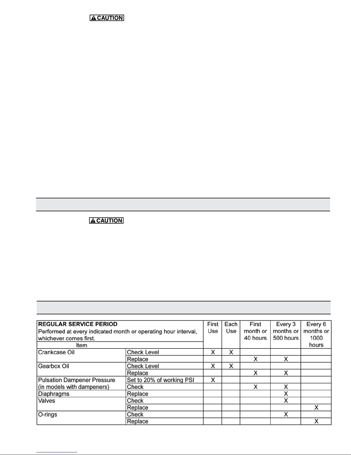
Maintenance Schedule
• Before returning pump for service/repair, drain
out all liquids and flush unit with neutralizing liquid. Then, drain the pump. Attach tag or include
written notice certifying that this has been done.
Please note that it is illegal to ship or transport
any hazardous chemicals without United States
Environmental Protection Agency Licensing.
Page 4
Installation
www.contree.com • 920-356-0121 • [email protected]
4
Pump Plumbing
Use only pipe, fittings, accessories, hose, etc. rated for
the maximum pressure rating of the pump.
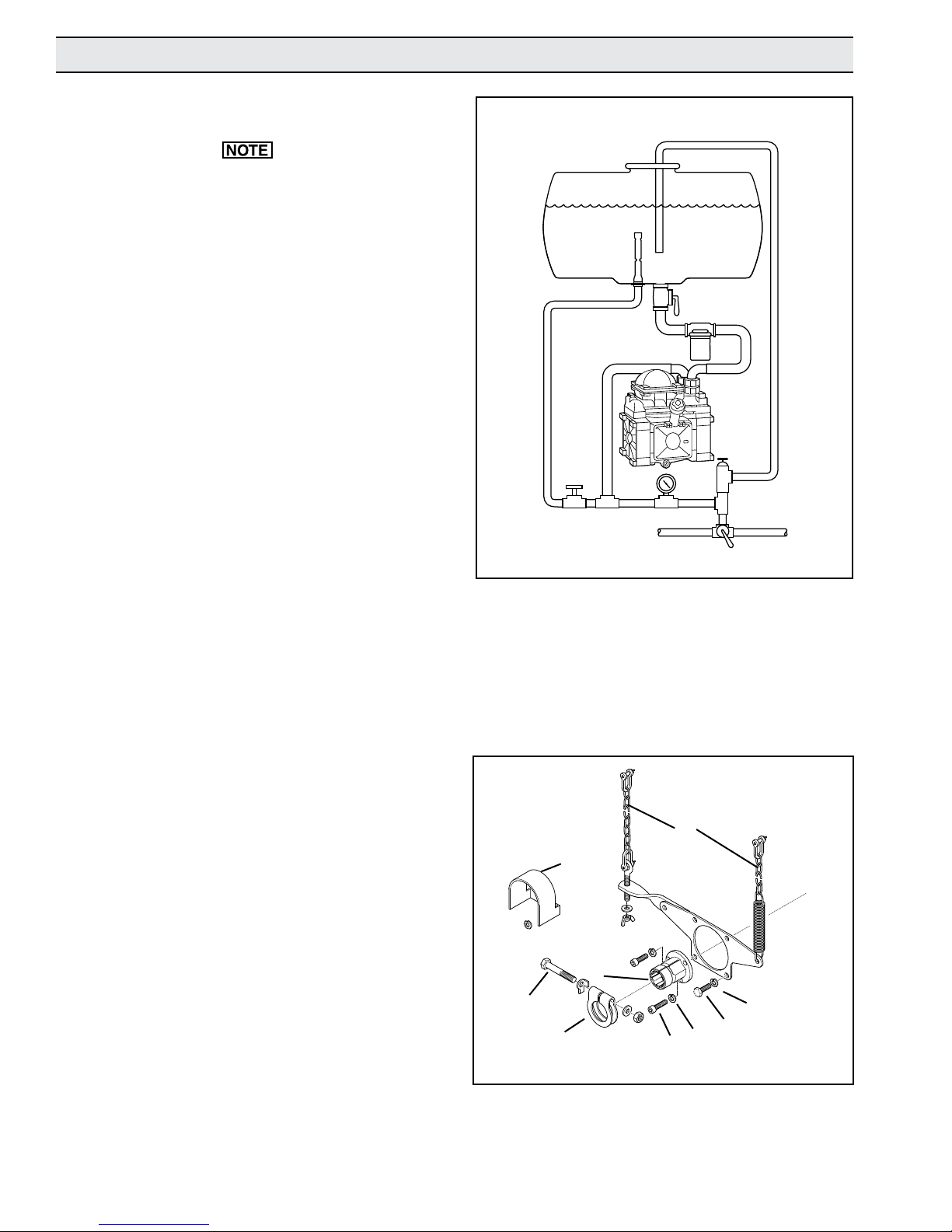
1. Always mount pump with oil sight tube in upright position
(See Figure 1).
2. The proper selection of hose type and size is vital to optimal performance.
a. Use good quality inlet hose, compatible with the fluids
being pumped and with good elasticity to reduce inlet
water hammer or pulsation. Be sure that hose is not too
rigid but capable of operating at low vacuums without
collapsing. The diameter of the inlet hose should be
at least that of the pump inlet port size and preferably
one size larger if the inlet line is longer than 6 feet [1.8
meters].
b. Use only approved high pressure hose on the discharge
side of pump.
3. Most ports are provided with hose barb connections. Use
good quality hose clamps and tighten them securely.
Diaphragm Pump Connection
Figure 1
Agitator
Agitation Line
Control
Valve
Strainer
Outlet
Pressure
Gauge
To Spray Gun
Tank
Shut-off
Pump
Relief Valve
To Boom Nozzles
Boom Shut-off
or Selector
Bypass Line
Shaft Adapter Kit Installation
Order the appropriate shaft kit according to the chart on
Page 2.
Female Splined Coupler Kits 9910-KIT1704 and
9910-KIT2204 (See Figure 2).
1. Slide the splined shaft adapter (Ref. 57) onto the pump
shaft and secure with three hex head bolts (Ref. 60) and
three washers (Ref. 61).
2. Position the torque arm bracket over the pump shaft.
3. Align the holes in the torque arm bracket with the two lower
holes of the pump; then, secure it to the pump with the two
bolts (Ref. 62) and washers (Ref. 61).
4. Position the clamp (Ref. 56) over the groove in the splined
shaft adapter; then, install the bolt (Ref. 71) into the clamp.
5. Slide the pump assembly onto PTO shaft and secure it with
the bolt (Ref. 71).
6. Position the shield (Ref. 105) over the shaft adapter, lining
up the holes with the remaining two holes in the torque
bracket. Secure with 2 bolts (Ref. 62) & washers (Ref. 61).
71
Figure 2
56
105
57
60
11
61
61
62
7. Attach chains (Ref. 11) to the bracket and secure to the
tractor to prevent rotation of the pump during operation.
Page 5
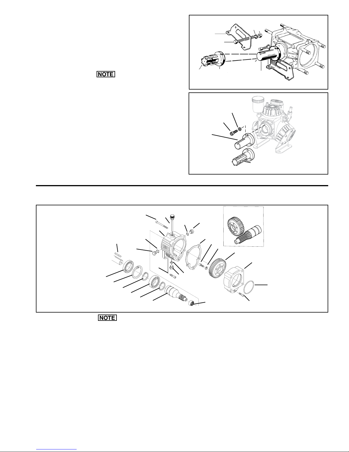
Solid Shaft Kits 9910-KIT1703, 9910-KIT1707,
www.contree.com • 920-356-0121 • [email protected]
5
9910-KIT2202 (See Figures 3 and 4)
Male Splined Shaft Kits 9910-KIT1702, 9910-KIT1706,
9910-KIT2200 (See Figures 3 and 4)
1. Install bases (Ref. 1) onto the pump securing with 2 bolts
(Ref. 2), 2 washers (Ref. 4), and 2 nuts (Ref. 3).
Models D303 and D403 are shipped with bases. Mount the
shaft adapter as shown in Figure 4.
2. Mount shaft adapter (Ref. 5A for KIT1703 & KIT1707, or
Ref. 5B for KIT1702 & KIT1706) onto the pump shaft and
secure with 3 bolts (Ref. 6) and 3 washers (Ref. 7).
3. Mount pump/base assembly securely to prevent movement.
5B
Figure 3
5A
KIT2202
Figure 4
1
2
Kit 1702
& 1706
6
4
3
5A
Kit 1703
& 1707
7
5B
KIT2200
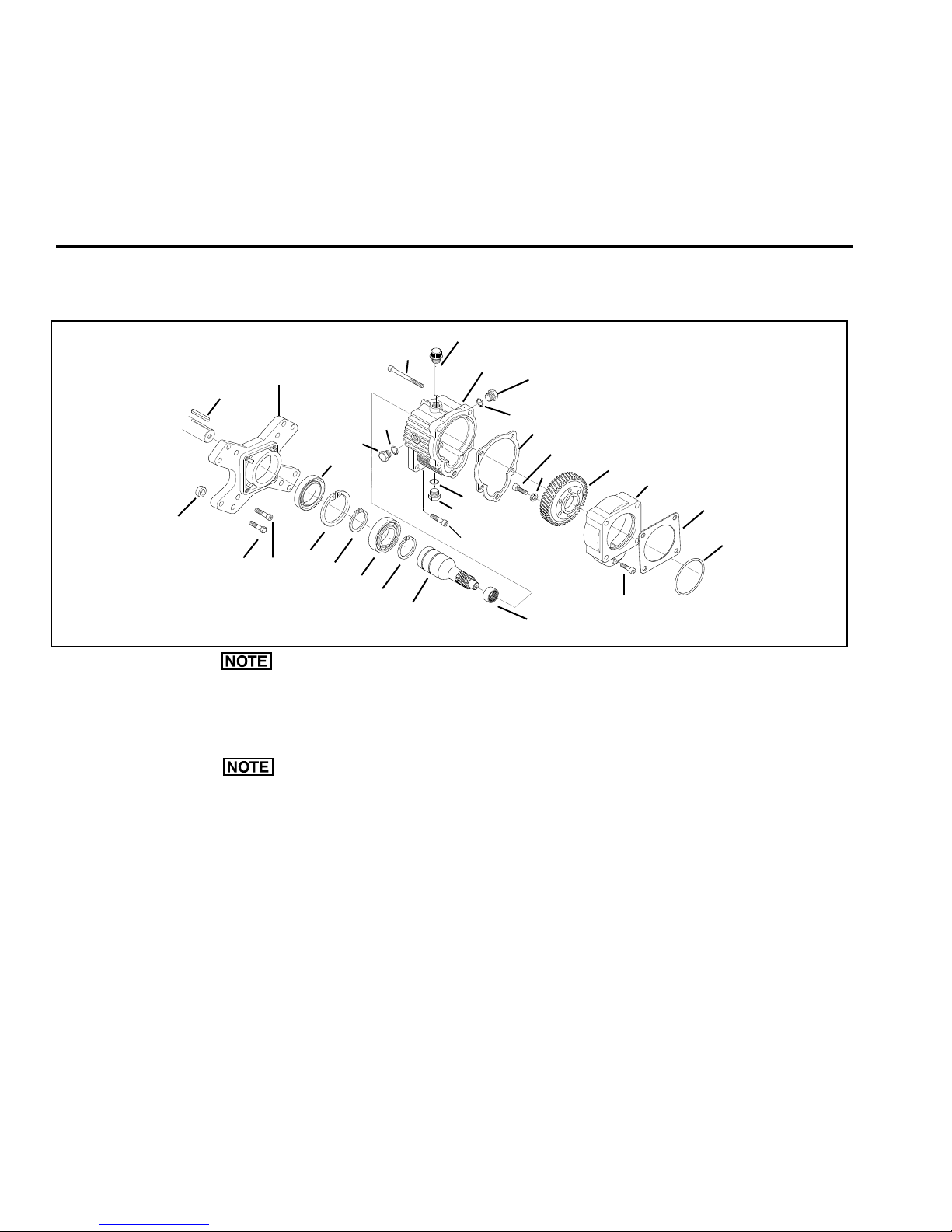
Installation Instructions for Gear Reduction Kit 9910-KIT1640
See Figure 5
7
6
Old Style
18
17
19
15
16
12
10
9
15
13
8
11
14
Figure 5
Hypro recommends a blue thread locking compound on all threaded fasteners that do not require
lock washers. Shaft key needs to be inspected
occasionally and replaced if worn.
The 9910-KIT1640 gear reducer is designed for direct
mounting the 9910-D30, D303, D403, D50, and D503
diaphragm pump onto a 5 hp gasoline engine with a
flange mounting and 3/4” solid shaft.
1. Lubricate the o-ring (Ref. 1) in the pump adapter
flange (Ref. 3). Slip the flange over the machined
surface of the casting, shaft end of pump.
2. Install the pump gear (Ref. 5) with the pilot diam-
eter of the gear inserted into the inner diameter of
10
9
9
20
10
4
the pump shaft. Secure firmly onto the shaft using
M10 x 25 socket head cap screws (Ref. 7) and lock
washers (Ref. 6).
3. Align the holes in the pump adapter flange (Ref. 3)
with threaded holes in the pump body. Lubricate the
gasket (Ref. 20) and place it in position on the gearbox body (Ref. 8). Install the gearbox body (Ref.
8) on the pump adapter flange (Ref. 3) and secure
firmly with M10 x 75 socket head cap screws (Ref.
12). Install the M8 x 20 socket head cap screw (Ref.
2) and securely tighten.
4. Insert the long key (Ref. 19) into the engine shaft
keyway. Align the keyway in the gear reducer Input
shaft (Ref. 14) and slide the pump and gear reducer
onto the engine shaft.
5
3
1
2
Page 6
5. Align the holes in the gearbox body (Ref. 8) with
www.contree.com • 920-356-0121 • [email protected]
6
threaded holes in engine boss. Insert 5/16”x1”-24
socket head cap screws through the gearbox body
(Ref. 8) and thread them into the threaded holes
in the engine boss. Securely tighten with the hex
7. Fill the gear case with 90W gear lube. To properly
fill, first tighten the bottom plug (Ref. 9); then remove
one side plug (Ref. 9) and the vent plug (Ref. 13).
Fill until the gear lube is no higher than the mark on
the dipstick.
wrench provided.
8. Replace and tighten the side plug and the vent plug.
6. The vent plug (Ref. 13) must always be installed or
reinstalled in the uppermost threaded hole of the
gearbox body (Ref. 8). Plugs (Ref. 9) and vent
plug (Ref. 13) are interchangeable for gear reducer
9. Please apply anti-seize to the motor shaft prior
to installing the gearbox.
mounting convenience.
Installation Instructions for Gear Reduction Kit 9910-KIT1642
See Figure 6
12
20
19
21
17
15
10
9
18
16
15
14
23
22
Figure 6
Hypro recommends a blue thread locking compound on all threaded fasteners that do not require
lock washers. Shaft keys need to be inspected occasionally and replaced if worn.
Hypro recommends support for all pumps in excess
of 25 Ibs [11.3 kg] in weight.
The 9910-KIT1642 gear reducer was designed for
direct mounting the 9910-D50 and D503 onto 8 hp gas
engines with flange mount and 1” solid shafts.
1. On the 9910-D50, the square metal plate (Ref. 34)
must be removed from the shaft side of the pump.
Lubricate the o-ring (Ref. 1) in the pump adapter
flange (Ref. 3). Slip the flange with gasket (Ref. 25)
over machined surface of casting of 9910-D503 or
the brass spacer ring installed on the shaft of the
9910-D50.
2. Install the pump gear (Ref. 5) with the pilot diameter of the gear inserted into the inner diameter of
the pump shaft. Secure firmly onto the shaft using
M10 x 25 socket head cap screws (Ref. 7) and lock
washers (Ref. 6).
13
9
8
10
11
10
9
24
7
6
4
5
3
25
1
2
3. Align the holes in the pump adapter flange (Ref.
3) with the threaded holes in the pump body.
Lubricate the gasket (Ref. 24) and place in position
on the gearbox body (Ref. 8). Install the gearbox
body (Ref. 8) on the pump adapter flange (Ref. 3)
and secure firmly with M10 x 75 socket head cap
screws (Ref. 12). Install the M8 x 20 socket head
cap screw (Ref. 2) and securely tighten.
4. Install the engine flange adapter (Ref. 21) raised
side out to the engine boss, using 5/16”x1”- 24
socket head cap screws (Ref. 19).
5. Insert the long key (Ref. 23) into the engine shaft
keyway. Align the keyway in gear reducer input
shaft (Ref. 14) and slide the pump and gear reducer
onto the engine shaft.
6. Align the holes in gearbox body (Ref. 8) with
the threaded holes in the engine flange adapter
(Ref. 21). Insert M8 x 25 socket head cap screws
(Ref. 11) through the gearbox body (Ref. 8)
and thread them into the engine flange adapter
(Ref. 21). Securely tighten with hex wrench provided.
7. The vent plug (Ref. 13) must always be installed or
reinstalled in the uppermost threaded hole of gear
Page 7

box body (Ref. 8). The plugs (Ref. 9) and vent plug
www.contree.com • 920-356-0121 • [email protected]
7
(Ref. 13) are all interchangeable for gear reducer
mounting convenience.
8. Fill the gear case with 90W gear lube. To properly
fill, first tighten bottom plug (Ref. 9); then remove
one side plug (Ref. 9) and vent plug (Ref. 13). Fill
Control Unit Kit Installation
until the gear lube is no higher than the mark on the
dipstick.
9. Replace and tighten the side plug and the vent plug.
10. Please apply anti-seize to the motor shaft
prior to installing the gearbox.
Control Unit 9910-KIT1990
The Model 9910-KIT1990 control unit is designed for
control of pressures to 290 psi and flows up to 6 gpm. It
mounts directly to a D252 pump.
Hypro recommends a blue thread locking compound on all threaded fasteners that do not require
lock washers.
1. Locate the discharge flange port on the discharge
manifold. Using a 13 mm wrench, remove the bolts
holding the flange to the manifold.
2. Remove the o-ring from the groove of the flange and
install it into the control unit flange.
3. Install the control unit onto the manifold where the
discharge port had been previously. Use the bolts
provided with the control to secure the control unit.
4. Install the hose barb outlets onto the control unit,
making sure the o-ring is in place on the plastic hose
barb.
Control Unit 9910-GS40GI
The 9910-GS40GI control unit is designed for convenient control of pressures up to 580 psi and flows up to
15 gpm. It can be mounted directly to the D30 and D50
pump, or it can be mounted remotely with KIT1741.
Direct Mounting Onto Pump
1. Locate the discharge flange port on the discharge
manifold. Using a 13 mm wrench, remove the nuts
holding the flange manifold.
2. Remove the o-ring from the groove of the flange and
install into the control unit flange.
Remote Mounting 9910-GS40GI
with Kit No. 9910-KIT1741
Hypro recommends a blue thread locking compound on all threaded fasteners that do not require
lock washers.
1. Locate and secure the mounting bracket in the
desired position.
2. Place o-rings (Ref. 110) into groove of relief valve
body (Ref. 105) and discharge flange housing (Ref.
101).
3. Assemble the control unit and discharge flange
housing onto the bracket and secure with the bolts
and nuts provided.
4. Use the high pressure hose to connect pump discharge port hose barb to the control unit inlet port
hose barb
Control Unit 9910-GR40
The Model 9910-GR40 control unit is designed for convenient control of pressure up to 580 psi and flows up
to 10.6 gpm. It consists of an adjustable pressure relief
valve, a manual pressure release lever, and two individual ball valve-controlled 1/2” hose barb outlets mounted
to the 9910-D303 and D403 discharge manifold.
Direct Mounting Onto Pump
1. Locate the discharge flange port on the discharge
manifold. Using a 13 mm wrench, remove the bolts
holding the flange to the manifold.
Hypro recommends a blue thread locking compound on all threaded fasteners that do not require
lock washers.
3. Install the control unit onto the manifold where the
discharge port had been previously. Use the nuts
previously removed to secure the control unit.
4. Install the hose barb outlets onto the control unit,
making sure the o-rings are in place on the hose
barbs.
2. Remove the o-ring from the groove of the flange and
install it into the control unit flange.
3. Install the control unit onto the manifold where the
discharge port had been previously. Use the bolts
provided with the control to secure the control unit.
4. Install the hose barb outlets onto the control unit,
making sure the o-ring is in place on the plastic hose
barb.
Remote Mounting 9910-GR40
with Kit No. 9910-KIT893
1. Locate and secure the mounting bracket in the
desired position.
Page 8
2. Place o-rings (Ref. 110) into groove of relief valve
www.contree.com • 920-356-0121 • [email protected]
8
body (Ref. 105) and discharge flange housing (Ref.
101).
3. Assemble the control unit and discharge flange
housing onto the bracket and secure with the bolts
and nuts provided.
4. Use the high pressure hose to connect pump discharge port hose barb to the control unit inlet port
hose barb.
Control Unit 9910-RM40
clamping should be used on all outlet hose connections.
Remote Mounting
Hypro recommends a blue thread locking compound on all threaded fasteners that do not require
lock washers.
1. Install mounting bracket (Ref. 29) in desired location
and secure with bolts (Ref. 31) and washers (Ref.
30); then attach the control to the bracket.
The 9910-RM40 control unit is designed for convenient
control of pressures up to 580 psi and flows up to 24
gpm. It consists of an adjustable pressure relief valve,
a manual pressure release lever, and two individual ball
valve-controlled 1/2” hose barb outlets. It can be direct
mounted onto the 9910-D503 discharge manifold.
Direct Mounting
Hypro recommends a blue thread locking compound
on all threaded fasteners that do not require lock
washers.
1. Locate the discharge manifold on the 9910-D503
(Ref. 25). With o-rings (Ref. 4) lubricated and in
position on control valve body (Ref. 28), plug into
discharge manifold. Lock into place with retainer clip
(Ref. 6).
2. Connect bypass hose to bypass hose barb (Ref. 1)
and run unrestricted to supply tank.
3. Connect the desired number of high pressure hoses
to the outlet hose barbs. Unused hose barbs can be
shut off with ball valves provided.
For all discharge hoses, use hose with an operating
pressure rating equal to or greater than the maximum pressure rating of the pump. High pressure
Always wear safety goggles when working with
spring-loaded fasteners or devices.
2. With o-rings (Ref. 4) lubricated and in position on
the control valve body (Ref. 28), plug it into the inlet
adapter (Ref. 32); then lock it into place with retaining clip (Ref. 6).
3. With o-rings (Ref. 4) lubricated and in position on the
other inlet adapter, plug it into the pump discharge
manifold (Ref. 25) and lock it into place with the
retaining clip.
4. Connect the NPT fitting on the discharge manifold of
the pump with the NPT fitting on the control unit with
the high pressure hose.
5. Connect the bypass hose to the bypass hose barb
(Ref. 2), then run it unrestricted to the supply tank.
6. Connect the desired number of high pressure
hoses to the outlet hose barbs on the control valve.
Unused hose barbs can be shut off with ball valves
provided.
For all discharge hoses, use hose with an operating
pressure rating equal to or greater than the maximum pressure rating of the pump. High pressure
clamping should be used on all outlet hose connections.
Operating Instructions
1. Be sure oil is halfway up to the clear oil sight tube. If
necessary, fill to the correct level with Hypro oil (part
number 2160-0038). Hypro oil is a specially formulated, high-grade, non-detergent, SAE 30 weight oil
formulated to prolong pump life.
2. Make sure the suction hose barb is tightly screwed
onto the suction union and that there are no air leaks
on the inlet side of the pump.
3. Check the charge pressure on the pulsation dampener before starting the pump. The pressure is
checked with a standard automotive air gauge. The
pressure should be at approximately 20% of the
maximum pressure that you will be operating the
pump at. Exercise caution when checking pressure
to avoid losing pre-charge.
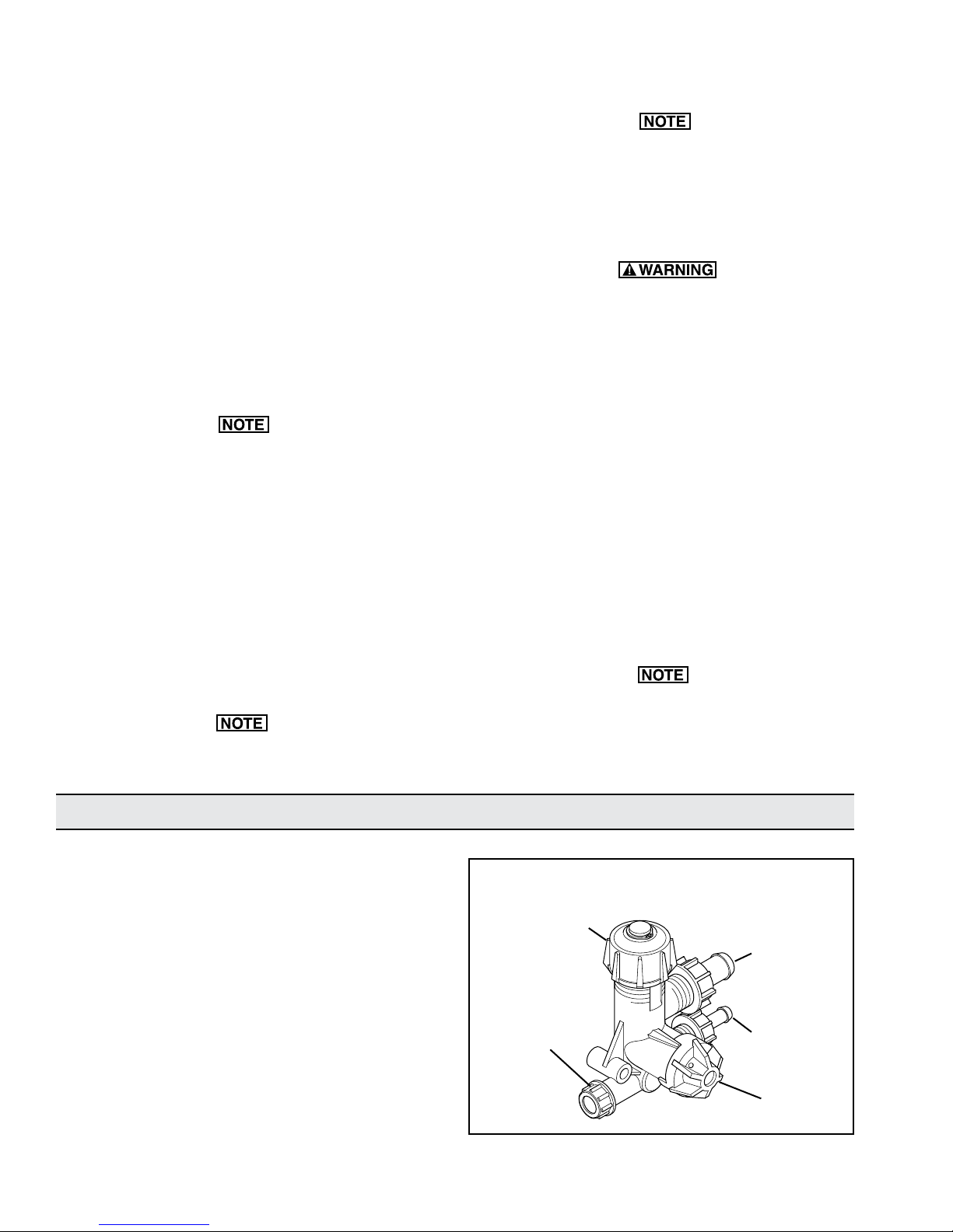
D252 Control Unit
Pressure Regulator
Adjustment Knob
Outlet Port
Figure 7
Plastic 5/8” Bypass
Hose Barb (Connect
directly to the tank
without restrictions
or ball valves.)
Brass 3/8”
Hose Barb
Outlet
Pressure
Release
Knob
Page 9
4. The relief valve bypass port should be connected
www.contree.com • 920-356-0121 • [email protected]
9
back to the liquid tank without restrictions. Do not
hook bypass line back to the inlet port or inlet hose.
9910-GS40GI Control Unit, Models D30 and D50
5. Allow the pump to start under low pressure by
removing restrictions on the outlet of the pump.
6. Start the pump and let it run for approximately one
minute at low pressure; then stop the pump and
check the oil level in the sight glass. Add Hypro oil if
necessary.
7. Adjust the pump to the desired pressure by changing the relief valve setting on the control unit, relief
valve or unloader.
On pump D252, (See Figure 7) first back out the relief
valve adjustment knob to zero. Then rotate the red
bypass selector knob so that the letter C (pressure) is
in the 12 o’clock up position. Adjust the pressure by
rotating the relief valve adjustment knob to the desired
pressure.
On pump D252, the restriction on the pump is removed
by rotating the red knob on the control unit so that the
letter A (bypass) on the knob is in the 12 o’clock up
position.
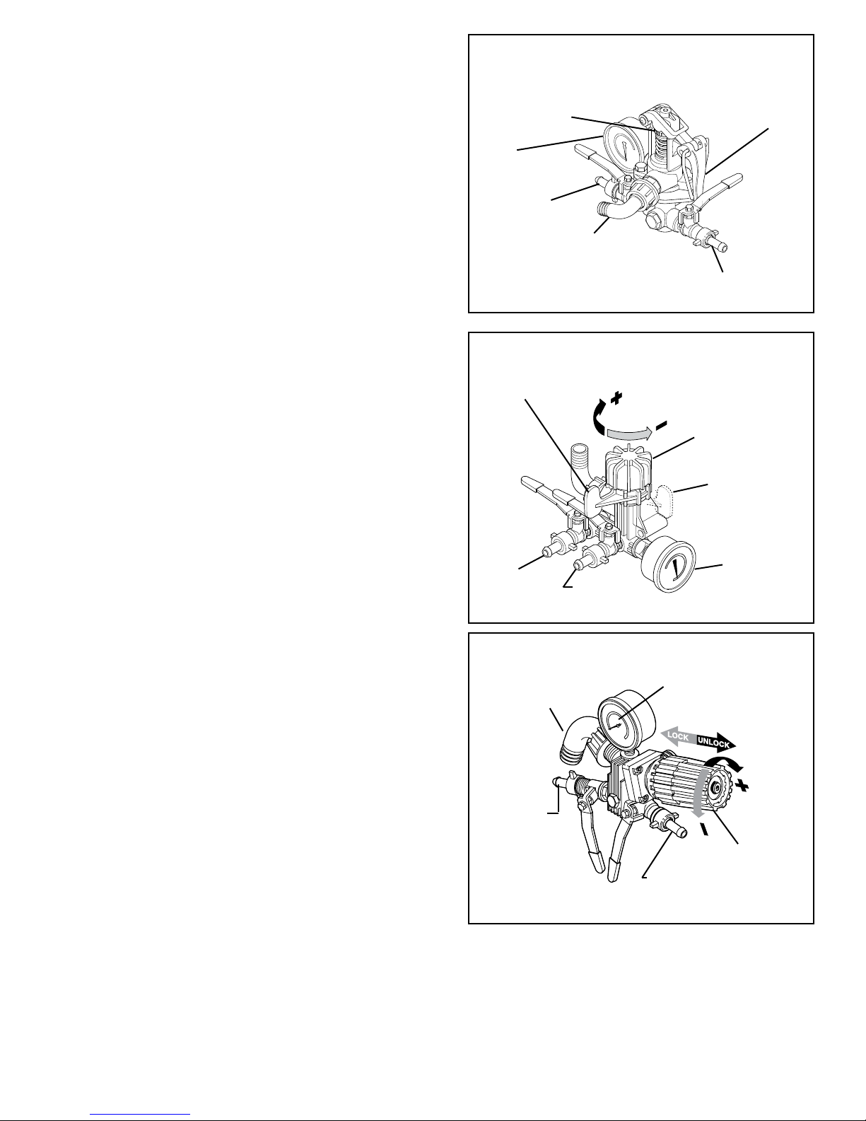
On pumps D30 and D50 (See Figure 8), adjust the
pressure by clamping the relief valve adjustment lever
down. With the bale hook in the number one position,
the pressure is about 100 psi [6.9 BAR]; number two is
about 250 psi [17.2 BAR]; number three is about 450
psi; number four is about 550 psi [37.9 BAR]. These
pressures can be adjusted by using the fine adjustment
knob located on top of the relief valve spring. The fine
adjustment knob can be rotated when the relief valve
lever is in the up position.
On pumps D30 and D50, the restriction is removed by
lifting up the relief valve adjustment lever with the bale
hook on the number 1 position.
Fine Adjustment
Knob
Pressure Gauge
Hose Barb
Outlet
Bypass Return Outlet
(Connect directly to the
tank without restrictions or
ball valves.)
Figure 8
Pressure Adjustment
& Release Lever
Hose Barb
Outlet
9910-GR40 Control Unit, Models D303 and D403
Pressure Control
Bypass Setting
Pressure Regulator
Adjustment Knob
Pressure Control
Pressure Setting
Hose Barb
Outlet
Hose Barb
Outlet
Pressure
Gauge
Figure 9
9910-RM40 Control Unit, Model D503
Bypass Hose Barb
(Connect directly to
the tank.)
Pressure
Gauge
On pumps D303 and D403 (See Figure 9), set the
pressure control to the pressure setting; then rotate the
pressure regulator to the desired pressure.
Hose Barb
Outlet
On pumps D503 and D503-GRGI (See Figure 10), slide
the pressure regulator adjustment knob to the UNLOCK
position; then rotate the pressure regulator adjustment
knob to the desired pressure.
On pumps D303, D430, and D50, the restriction is
Figure 10
removed by lifting up the relief valve adjustment lever
with the bale hook on the number 1 position.
Pressure Regulator
Adjustment Knob
Hose Barb
Outlet
Page 10
Maintenance Instructions for All Models
www.contree.com • 920-356-0121 • [email protected]
10
1. After usage, flush the pump with clean water.
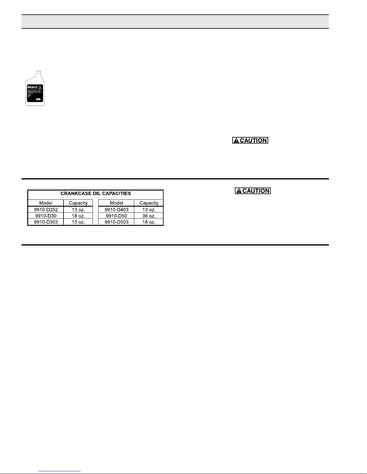
2. Hypro diaphragm pumps come with oil in the crankcase. Hypro recommends changing oil after 40 hours
of break-in operation and every three months
or 500 hours, whichever comes first. Use
Hypro oil (part number 2160-0038). Hypro
oil is a specially formulated, high-grade,
non-detergent, SAE 30 weight oil formulated
to prolong pump life.
To drain the oil:
D252
Remove the oil fill cap, turn the pump upside down
and rotate the shaft until oil stops flowing out. (D252
gear reduction oil requirements: use 80-90 wt. gear
lube and fill to level hole on gear reduction side.)
D30, D50, D303, D403 and D503
Remove the drain plug (2406-0023) (or 9910-770070 on
D503) and the oil sight glass covers, and rotate shaft until
the oil stops flowing out. Re-install the drain plug.
To fill the pump with oil, slowly pour oil into sight tube
while turning the pump shaft. Turning the pump shaft
purges all the air out of the crankcase. Always change oil
when replacing diaphragms.
For winter storage or if a freezing condition will be
encountered, flush the pump with a 50/50 mixture of
water and antifreeze.
The bypass return outlet on all control units must be
connected directly to the tank without restrictions or
ball valves.
Oil crankcase capacities are approximate. Fill oil to
proper level in sight glass. Always make sure all the
air is purged out of crankcase prior to operating.
Valve Replacement
Occasionally debris may cause improper seating of the
valves or damage to the o-rings. To check for this problem, follow these steps.
D252
Remove the head bolts and the head. Remove the valve
caps and the valve assemblies. Replace the valve assemblies and o-rings, and reassemble.
D30, D50, D303 and D403
Remove the pump manifolds. With the manifolds removed,
the valves can easily be removed and inspected for debris
and wear. Replace valves, o-rings and manifolds.
D503
Remove valve retainers. With retainers removed, valves
and o-rings can easily be removed and inspected.
Replace valves, o-rings and valve retainers.
Page 11
Maintenance Instructions for All Models
www.contree.com • 920-356-0121 • [email protected]
11
Diaphragm Replacement: D30, D252, D303, D403
and D503
Change diaphragms every 500 hours or three months,
whichever comes first.
1. Drain oil from crankcase as instructed previously.
2. Remove pump head bolts and heads.
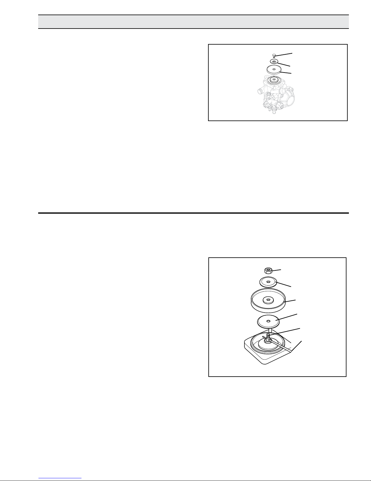
3. Remove the bolt securing the diaphragm (See
Figure 11).
4. Remove the old diaphragm and the washer (See
Figure 11).
5. Install a new diaphragm; then turn the crankshaft to
bring the piston to its down-stroke and seat the diaphragm into the sleeve groove.
6. Install the washer and bolts removed in steps 3 and 4.
7. Replace the pulsation dampener diaphragm by first
bleeding the air from the dampener. Remove the
bolts from the dampener cover and replace the diaphragm. Reassemble the cover in place and charge
the dampener to 20% of the operating pressure.
8. Refill the crankcase with Hypro oil (part number
2160-0038). Rotate the shaft to distribute the oil, and
fill to proper level.
Diaphragm Replacement: D50
Change diaphragms every 500 hours or three months,
whichever comes first.
1. Drain oil from crankcase as instructed previously.
2. Remove the pump manifolds and valves.
3. Remove the pump head retaining nuts and heads.
4. Turn the crankshaft to bring the diaphragm to the
top of its stroke. Insert a drift pin into the hole in the
retaining bolt to hold it in place. Remove the retaining
nut, retaining washer and the diaphragm (see Figure
12).
5. Turn the crankshaft to bring the piston to the bottom
of its stroke and seat the new diaphragm into the
sleeve groove. Install the retaining washer and tighten the retaining nut while holding the retaining stud in
place with the drift pin. Clean any excess oil from the
area and install the heads, valves and manifolds.
6. Replace the pulsation dampener diaphragm by first
bleeding the air from the dampener. Remove the
cover retaining bolts from the dampener cover and
replace the diaphragm. Reassemble the cover and
bolts in place and charge the dampener to 20% of
operating pressure.
7. Refill the crankcase with Hypro oil (part number 2160-
0038). Rotate shaft to distribute oil, and fill to proper
level.
Retaining Nut
Retaining Washer
Diaphragm
Support Washer
Retaining Bolt
Drift Pin
Figure 12
Page 12
Troubleshooting
MOTPMYSS(ESUACELBABORP) ONITCAEVITCERROC
.retawwardtonseodpmupeTh ngitaeserasevlaveromroenO
.ylreporpmi
.sirbedrofkcehcdnaevlavevomeR
ehtenimaxE.dnuofsirbedynaevomeR
.mehtnaelcdnasgnitaesevlav
.despallocrodeggulpsienilnoitcuS
.reniartsdeggolC
naelC
.enilnoitcusehtnaelcdnaenimaxE
.reniartseht
.ralugerrisiwolfdiuqilehT renepmadnoitaslupehtniegrahcehT
.tcerrocnisi
noitaslupehtnierusserpehtkcehC
er. (It should be 20% of your spraynepmad
gnitaeserasevlaveromroenO
.ylreporpmi
.sirbedrofkcehcdnaevlavevomeR
ehtenimaxE.dnuofsirbedynaevomeR
.mehtnaelcdnasgnitaesevlav
.ysionsipmupehtdnaspordtuptu
O.
w.olootsilevellioehT ehtpuyawflah(leveltcerrocehtotlioddA
.)ebutthgis
rotropegrahcsidehtfotuosemocliO
.rolocyklimasilio
.tilpsevahsmgarhpaidro moreenO ehtniarD.sdaehdnadlofinamehtevomeR
.retawfoesacknarcehtnaelcdnalio
dna,sdaeh,smgarhpaidehtecalpeR
trap(liOorpyHhtiwllifeR.dlofinam
.)8300-0612rebmun
pressure.)
www.contree.com • 920-356-0121 • [email protected]
12
Page 13
Replacement Parts
www.contree.com • 920-356-0121 • [email protected]
13
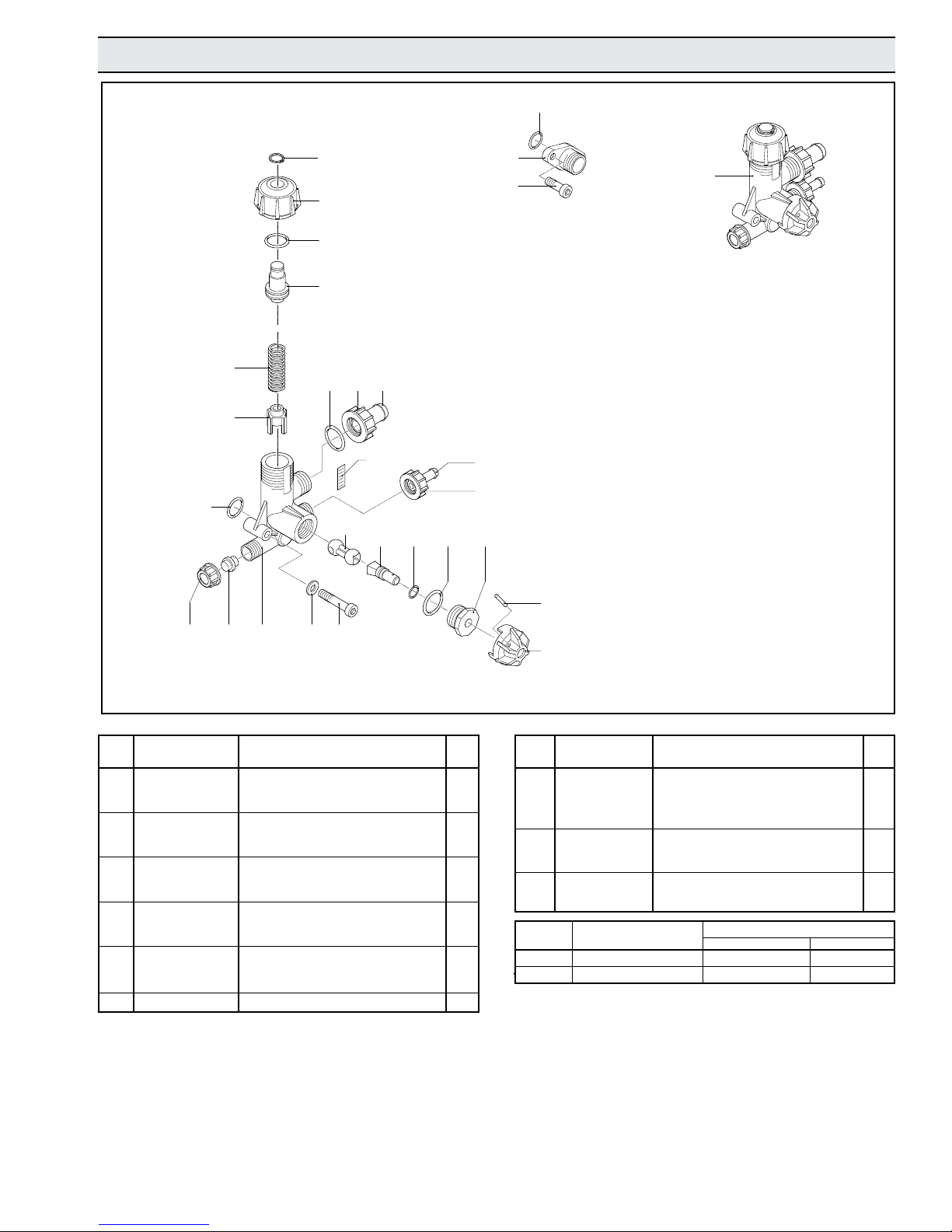
9910-KIT1990
56
22
57
60
59
22
58
53
43
52
54
49
51
48
22
50
35
45
105
106
22
109
9910-KIT1990 also includes
Ref. Nos. 22, 41 and 42.
35
41
42
40
39
Figure 13
Ref. Part
No. Number Description Qty.
22 9910-480440 O-Ring 4
35 9910-800520 Ring Nut 2
39 9910-800540 Plug 1
40 9910-800400 Valve Body 1
41 9910-550331 Washer 2
42 9910-800410 M6 x 40 Bolt 2
43 9910-800430 Valve 1
45 9910-800500 Ring Nut 1
46 9910-800510 Knob 1
47 9910-390330 Pin 1
48 9910-800560 O-Ring 1
49 9910-800490 Positioning Rod 1
50 9910-800530 Hose Barb (Outlet) 3/8” 1
51 9910-800670 Hose Barb (Inlet) 1/2” bypass 1
52 9910-800680 Ring Nut 1
53 9910-740290 O-Ring 1
47
46
Ref. Part
No. Number Description Qty.
54 9910-800480 ATM Scale Adhesive 1
56 9910-800440 Lower Spring Guide 1
57 9910-800450 Spring 1
58 9910-800460 Upper Spring Guide 1
59 9910-800470 Adjustment Knob 1
60 9910-480550 Retaining Ring 2
105 9910-450146 Flange 1
106 9910-880280 M6 x 18 Bolt 2
109 9910-KIT1990 Complete Relief Valve Ass’y. 1
Ref. No. Description Tightening Torque
In. Lbs. Nm
42 Bolt 171.4 19.6
106 Bolt 171.4 19.6
Page 14
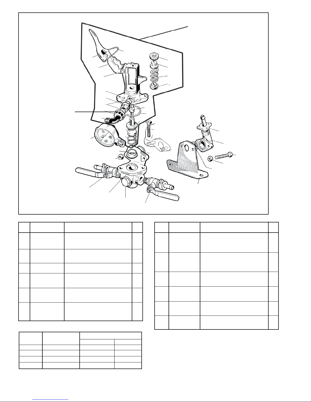
Model 9910-GS40GI Control Unit
www.contree.com • 920-356-0121 • [email protected]
14
94
93
92
91
Bypass Hose Barb —
Connect directly to tank
without restrictions
or ball valves.
90
89
87
86
95
83
85
84
97
98
Sub Assembly —
9910-1923 Includes parts
83-87, 89-99, 113 and 114.
96
9910-GS40GI Control Unit
mounts directly on pump
99
114
111
106B
113
109
104
105
107
Figure 14
Ref. Part
No. Number Description Qty.
1
83
9910-320433 Relief Valve Poppet Retainer 1
841 9910-320511 Gasket Seal O-Ring 1
851 9910-390140 Tension Spring Guide/Seal 1
86 9910-550460 Hose Barb 1/2” 1
87 9910-550450 Barb Nut 1
89 9910-180101 O-Ring 2
90 9910-550440 Threaded Adapter 1
91 9910-320410 Tension Spring Housing 1
92 9910-320480 Pin 1
93 9910-320460 Lever Guide 1
94 9910-320470 Pressure Release Lever 1
95 9910-320490 Locking Clip 1
96 9910-320450 Pressure Adjustment Nut 1
97 9910-320440 Threaded Guide 1
98 9910-110190 Tension Spring 1
98 9910-620810 Tension Spring (Opt.)
(under 100 psi) 1
106A
112
110
100
9910-KIT1741 Remote Mounting Kit includes
mounting bracket and hose barb shown above.
102
101
103
104
110
Ref. Part
No. Number Description Qty.
99 9910-230120 Tension Spring Retainer 1
100 9910-320406 Remote Discharge
Mounting Bracket 1
101 9910-450145 Discharge Flange Housing 1
102 9910-110130 1/2” Hose Barb & Nut--(3/8” 1
9910-110131)
103 9910-160660 M8 x 35 Bolt 2
104 9910-390270 Nut 2
105 9910-620220 Relief Valve Body 1
106A 9910-KIT2497 Ball Valve (left) 1
106B 9910-130491 Ball Valve (right) 1
107 9910-130171 Plug 1
1091 9910-450110 Spring Holder 1
110 9910-550350 O-Ring 1
111 9910-550545 Pressure Gauge (Oil-filled) 1
112 9910-180370 M8 x 25 Bolt 2
1131 9910-320420 Tension Spring 1
1141 9910-110122 Relief Valve Seat (Viton) (Std.) 1
114 9910-110121 Relief Valve Seat (Urethane) 1
Ref. No. Description Tightening Torque
In. Lbs. Nm
103 Bolt 171.4 19.6
104 Nut 171.4 19.6
107 Plug 171.4 19.6
112 Bolt 171.4 19.6
REPAIR & MAINTENANCE KIT AVAILABLE
1
Control Unit Parts Kit No. 9910-KIT1757 consists of one each of:
Ref. 83 Relief Valve Poppet Retainer, Ref. 84 Gasket Seal O-Ring,
Ref. 85 Tension Spring Guide, Ref. 109 Spring Holder, Ref. 113
Tension Spring and Ref. 114 Relief Valve Seat.
Page 15
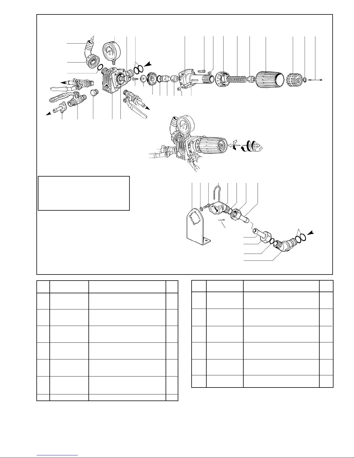
Model 9910-RM40 Control Unit
www.contree.com • 920-356-0121 • [email protected]
15
5
1
3
13
26 27 28
33
Repair Kit No. 3430-0605 Consists of:
Ref. 4 (4) O-ring, Ref. 9 (1) Valve seat,
Ref. 11 (1) Valve poppet, Ref. 12 (1)
Diaphragm and Ref. 13 (4) O-ring
13
39
38
15
16
18
17
29
4
9
10
11
12
13
14
30
20
31
16
6
21
32
13
22
37
41
35
23
24
9910-KIT1897 Remote Mounting
Kit includes a mounting bracket and
hose barbs as pictured at right.
Figure 14-A
Ref. Part
No. Number Description Qty.
1 9910-550460 Hose Barb 1/2” 1
3 9910-550450 Hose Barb Nut 1
4 9910-390180 O-Ring 4
5 9910-550545 Gauge 1
6 9910-1040690 Retaining Clip 1
9 9910-1150520 Valve Seat 1
10 9910-680560 M6 x 16 Bolt 1
11 9910-1040640 Valve Poppet 1
12 9910-1040630 Diaphragm 1
13 9910-880830 O-Ring 5
14 9910-1040620 Piston 1
15 9910-1150560 Spacer 1
16 9910-1150600 Retaining Ring 2
17 9910-1150540 Pin 1
18 9910-1150510 Adjustment Body 1
20 9910-780330 M6 x 20 Bolt 4
21 9910-1150530 Bypass Ring 1
22 9910-394760 Spring 1
23 9910-1150550 Adjustment Knob 1
40
4
35
37
13
36
Ref. Part
No. Number Description Qty.
24 9910-1150570 Spring Retainer 1
26 9910-KIT2497 Ball Valve Assy. 1/2” Hose Barb 2
27 9910-130171 Plug 1
28 9910-1150500 Body-RM40 1
29 9910-1150590 Mounting Bracket 1
30 9910-390311 Washer 2
31 9910-180431 M8 x 16 Bolt 2
32 9910-1040770 Inlet Adapter 1
33 9910-110130 Hose Barb 1/2” 2
34 9910-1040950 Cotter Pin 1
35 9910-1150580 Barb 2
36 9910-1040760 Outlet Adapter 1
37 9910-1040790 Nut 2
38 9910-1150650 M3 x 60 Bolt 1
39 9910-480550 Retaining Ring 1
40 9910-1040950 Cotter Pin 1
41 9910-1150660 Spacer 1
Page 16
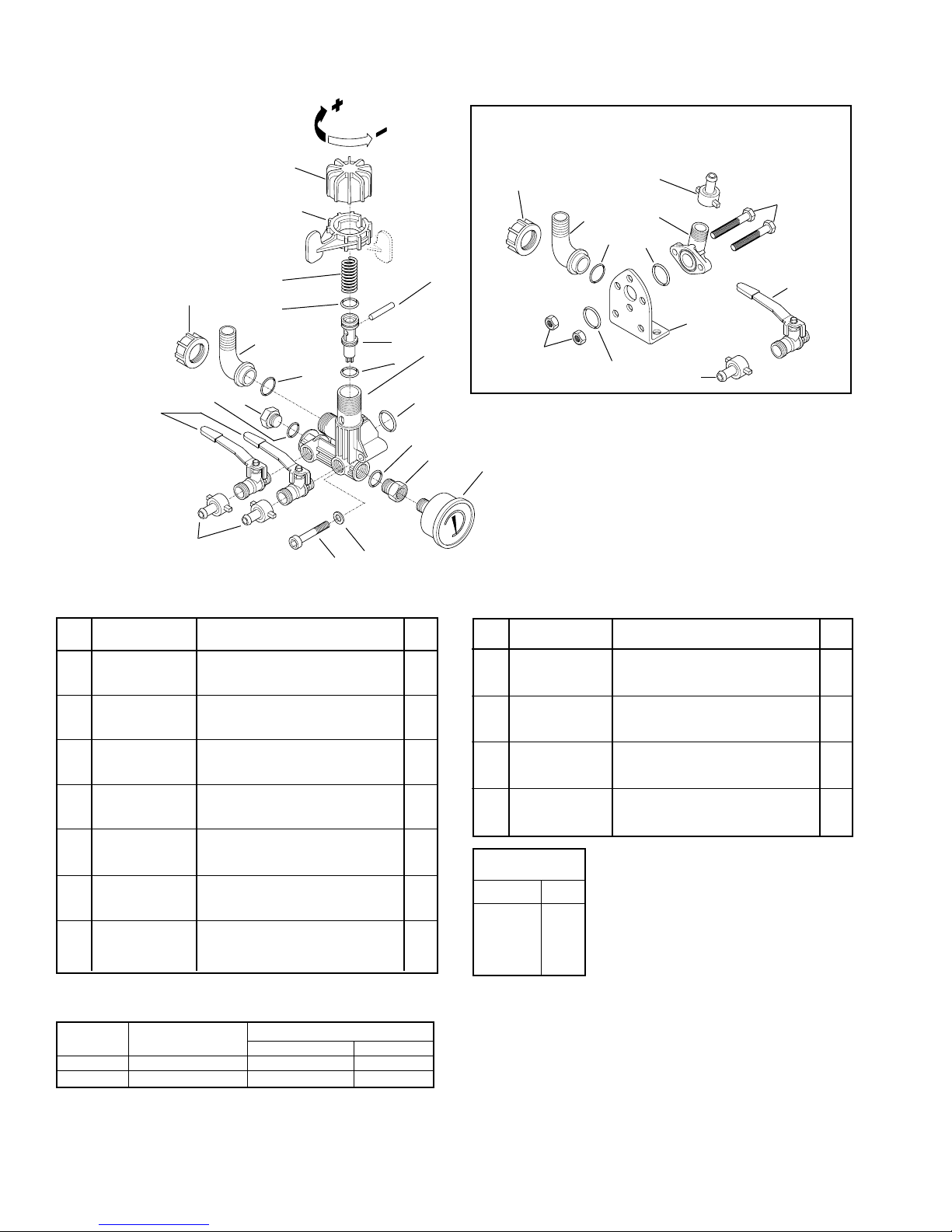
Model 9910-GR40 Control Unit
www.contree.com • 920-356-0121 • [email protected]
16
1
2
9910-KIT893
Supplemental Mounting Kit
19
18
17
26
21
22
23
3
Figure 15
13
19
15
14
16
18
4
6
17
12
7
20
15
11
9910-GR40
Ref. Part
No. Number Description Qty.
1 9910-1880220 Adjustment Knob 1
2 9910-1880210 Ring Nut 1
3 9910-1880271 Spring 1
4 9910-480440 O-Ring 1
5 9910-1880240 Pin 1
6 9910-1880230 Jet 1
7 9910-1880260 O-Ring 1
8 9910-1880200 Valve Body 1
9 9910-1880290 Pressure Gauge 1
10 9910-1880250 Pipe Reducer 1
11 9910-390311 Washer 2
12 9910-680360 M8 x 50 Bolt 2
13 9910-130491 Ball Valve 2
141 9910-110131 Hose Fitting 2
15 9910-740290 O-Ring 2
16 9910-130171 Plug 4
171 9910-880830 O-Ring 1
181 9910-550460 Elbow 1
191 9910-550450 Ring Nut 1
201 9919-1140450 O-Ring 1
1
Denotes 9910-KIT893 Items
5
24
8
10
9
25
20
14
9910-KIT893
Ref. Part
No. Number Description Qty.
141 9910-110131 Hose Fitting 2
171 9910-880830 O-Ring 1
181 9910-550460 Elbow 1
191 9910-550450 Ring Nut 1
201 9919-1140450 O-Ring 1
211 9910-1880310 Bolt 2
221 9910-450145 Flange 1
231 9910-550350 O-Ring 1
241 9910-320406 Bracket 1
251 9910-390270 Nut 2
26 9910-110130 Hose Fitting 1
27 9910-130491 Ball Valve 1
9910-KIT2488
Valve Repair Kit
Ref. No. Qty.
3 1
4 1
5 1
6 1
7 1
27
Ref. No. Description Tightening Torque
In. Lbs. Nm
12 Bolt 87.5 9.8
16 Plug 87.5 9.8
Page 17
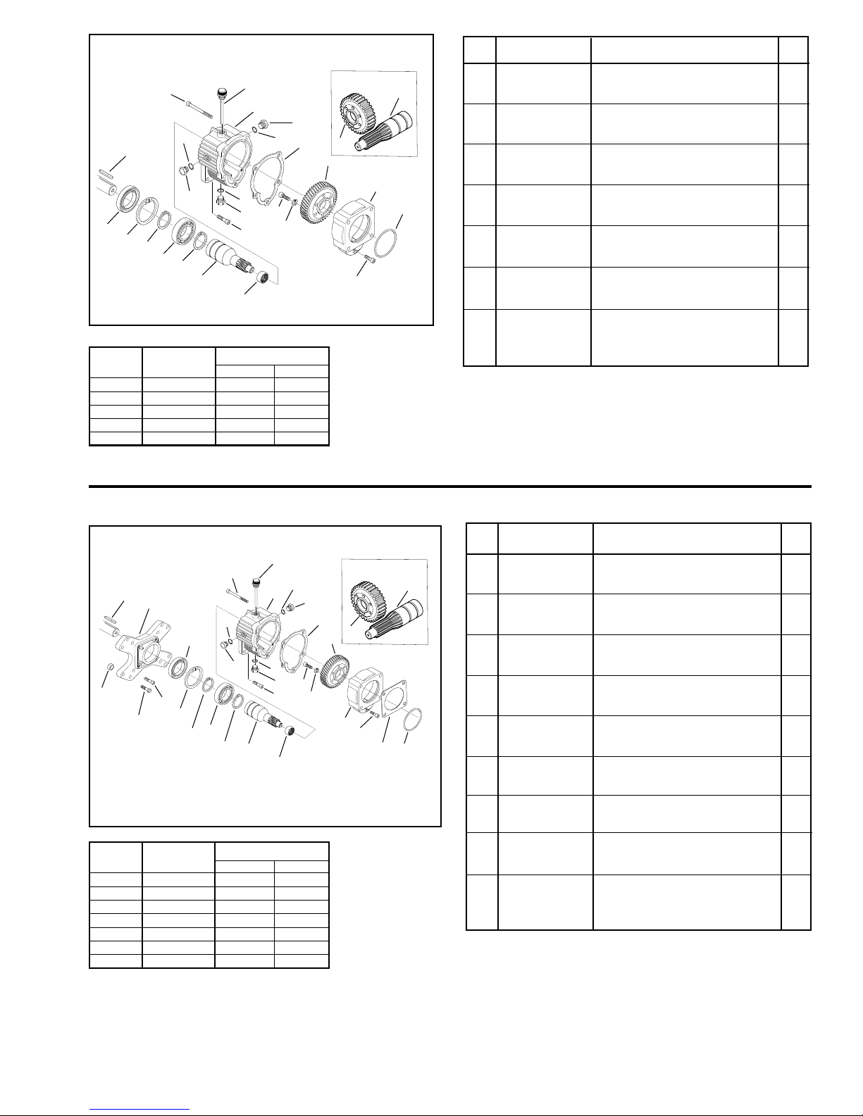
Gearbox 9910-KIT1640
www.contree.com • 920-356-0121 • [email protected]
17
11
13
8
9
10
20
10
7
9
6
4
12
15
16
10
9
15
14
18
19
17
Figure 16
Ref. No. Description Tightening Torque
In. Lbs. Nm
2 Bolt 218.7 24.5
7 Bolt 171.4 19.6
9 Plug 171.4 19.6
11 Bolt 218.7 24.5
12 Bolt 218.7 24.5
Old Style
27
5
2
Ref. Part
No. Number Description Qty.
1 9910-620561 O-Ring 1
28
3
1
2 9910-180030 M8 x 20 Bolt 1
3 9910-621000 Pump Adapter Flange 1
4 9910-620990 Bearing 1
5 9910-651620 Gear 1
6 9910-200231 Lock Washer 6
7 9910-620470 M10 x 20 Bolt 3
8 9910-620960 Gearbox Body 1
9 2406-0023 Plug 2
10 9910-740290 O-Ring 2
11 9910-651000 5/16 x 24 UNF x 1 Bolt 4
12 9910-621010 M10 x 75 Bolt 4
13 9910-1140370 Vent Plug 1
14 9910-621660 Pinion Gear 1
15 9910-320240 Retaining Ring (Ext.) 2
16 9910-961780 Bearing 1
17 9910-961790 Retaining Ring (Int.) 1
18 9910-961800 Seal 1
19 9910-881090 Key 1
20 9910-620950 Gasket 1
27 N/A Gear 1
28 N/A Pinion Gear 1
Gearbox 9910-KIT1642
12
23
21
10
18
22
20
19
17
15
16
15
Figure 17
Ref. No. Description Tightening Torque
In. Lbs. Nm
2 Bolt 218.7 24.5
7 Bolt 171.4 19.6
9 Plug 171.4 19.6
11 Bolt 218.7 24.5
12 Bolt 218.7 24.5
19 Bolt 218.7 24.5
20 Bolt 218.7 24.5
13
10
8
9
10
9
7
11
14
4
9
24
6
Old Style
27
5
3
2
25
28
1
Ref. Part
No. Number Description Qty.
1 9910-620561 O-Ring 1
2 9910-180030 M8 x 20 Bolt 1
3 9910-621000 Pump Adapter Flange 1
4 9910-620990 Bearing 1
5 9910-651620 Gear 1
6 9910-200231 Lock Washer 6
7 9910-160671 M10 x 25 Bolt 1” Long (D50) 3
7 9910-620470 M10 x 20 Bolt 3/4” Long (D30) 3
8 9910-620960 Gearbox Body 1
9 2406-0023 Plug 3
10 9910-740290 O-Ring 3
11 9910-540290 Bolt 4
12 9910-621010 M10 x 75 Bolt 4
13 9910-1140370 Vent Plug 1
14 9910-651610 Pinion Gear 1
15 9910-320240 Retaining Ring (Ext.) 2
16 9910-961780 Bearing 1
17 9910-961790 Retaining Ring (Int.) 1
18 9910-961800 Seal 1
19 9910-651000 5/16 x 24 UNF x 1 Bolt 4
20 9910-961900 3/8 x 16 UNC x 1-1/4 Bolt 4
21 9910-1320940 Engine Adapter Flange 1
22 9910-961770 Spacer 4
23 9910-650990 Key 1
24 9910-620950 Gasket 1
25 9910-650270 Gasket 1
27 N/A Gear 1
28 N/A Pinion Gear 1
Page 18
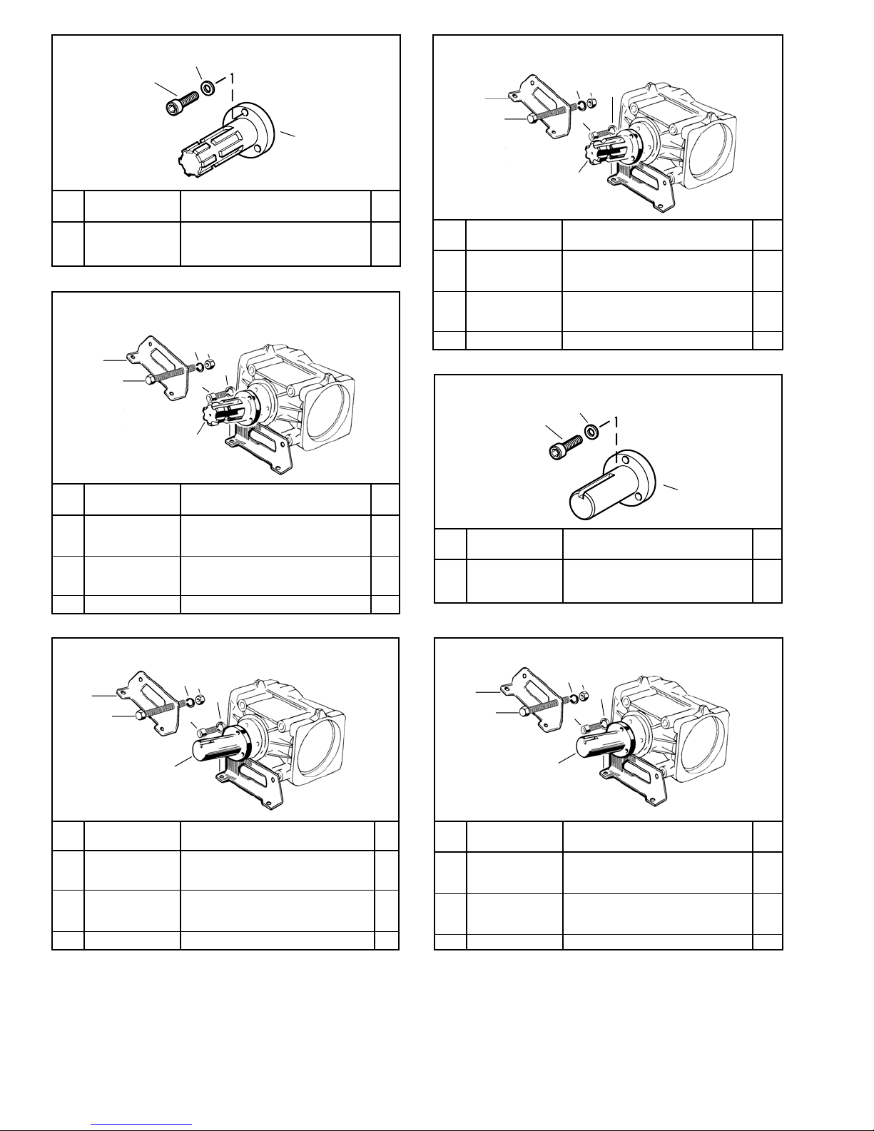
9910-KIT2200
www.contree.com • 920-356-0121 • [email protected]
18
1
2
3
9910-KIT1702
1
2
4
3
7
6
Figure 18
Ref. Part
No. Number Description Qty.
1 9910-160671 M10 x 25 Socket Head Cap Screw 3
2 9910-200231 Lock Washer 3
3 9910-620240 Shaft 1
9910-KIT1706
4
1
2
Figure 19
Ref. Part
No. Number Description Qty.
1 9910-320392 Pump Base 2
2 9910-750060 M8 x 75 Socket Head Cap Screw 2
3 9910-320130 Nut 2
4 9910-320131 Lock Washer 2
5 9910-620240 Male 6-Spline 13/8” PTO Shaft 1
6 9910-540300 M10 x 20 Socket Head Cap Screw 3
7 9910-200231 Lock Washer 3
3
7
6
5
5
Figure 21
Ref. Part
No. Number Description Qty.
1 9910-380200 Pump Base 2
2 9910-380210 M8 x 75 Socket Head Cap Screw 2
3 9910-380240 Nut 2
4 9910-380241 Lock Washer 2
5 9910-620240 Male 6-Spline 13/8” PTO Shaft 1
6 9910-620470 M10 x 20 Socket Head Cap Screw 3
7 9910-200231 Lock Washer 3
9910-KIT2202
2
1
3
Figure 22
Ref. Part
No. Number Description Qty.
1 9910-160671 M10 x 25 Socket Head Cap Screw 3
2 9910-200231 Lock Washer 3
3 9910-621600 1” Solid Keyed Shaft 1
9910-KIT1703
4
1
2
Figure 20
Ref. Part
No. Number Description Qty.
1 9910-380200 Pump Base 2
2 9910-380210 M8 x 75 Socket Head Cap Screw 2
3 9910-380240 Nut 2
4 9910-380241 Lock Washer 2
5 9910-621600 1” Solid Keyed PTO Shaft 23/8” long 1
6 9910-620470 M10 x 30 Socket Head Cap Screw 3
7 9910-200231 Lock Washer 3
3
7
6
5
9910-KIT1707
4
1
2
Figure 23
Ref. Part
No. Number Description Qty.
1 9910-320392 Pump Base 2
2 9910-750060 M8 x 75 Socket Head Cap Screw 2
3 9910-320130 Nut 2
4 9910-320131 Lock Washer 2
5 9910-621600 1” Solid Keyed PTO Shaft 1
6 9910-540300 M10 x 30 Socket Head Cap Screw 3
7 9910-200231 Lock Washer 3
3
7
6
5
Page 19
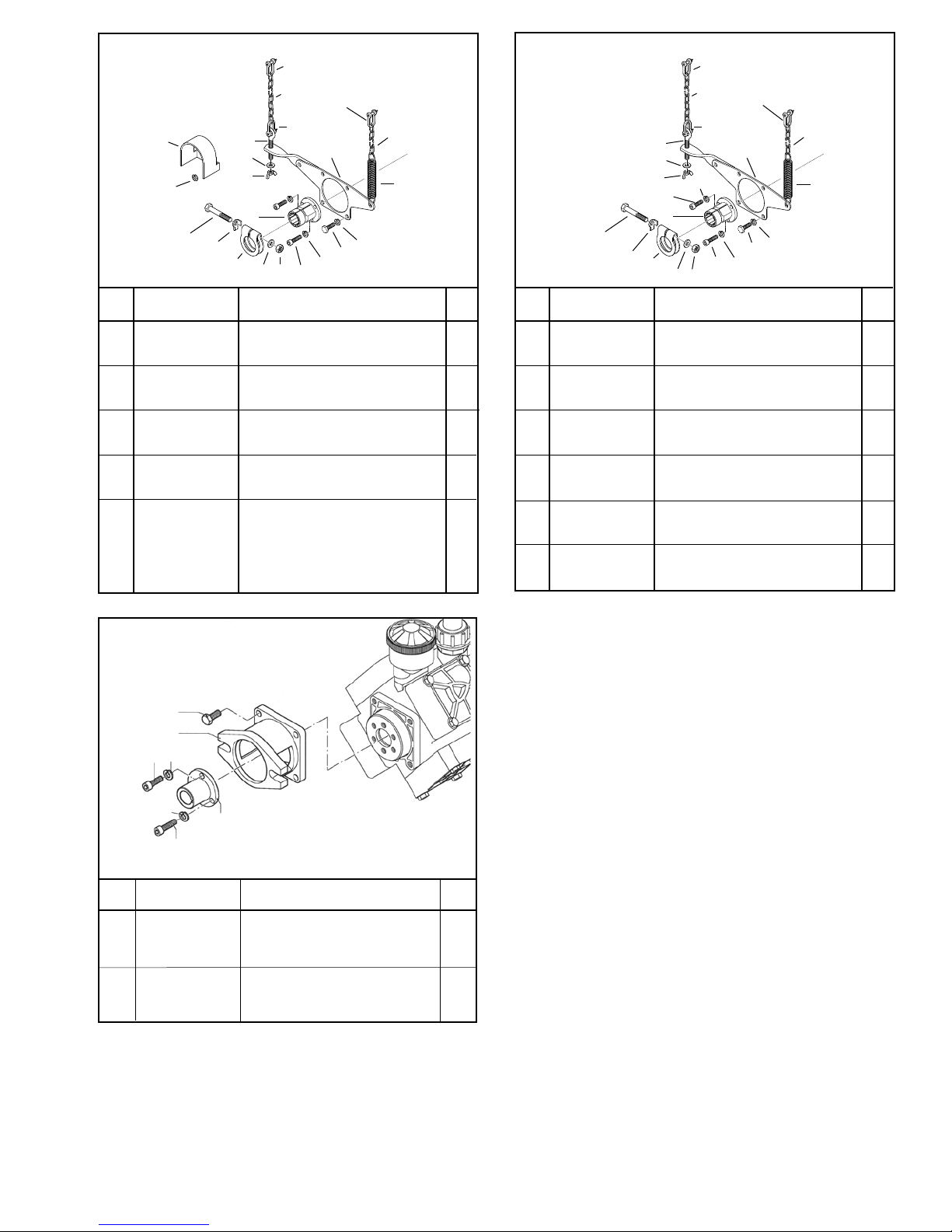
9910-KIT1704
www.contree.com • 920-356-0121 • [email protected]
19
58
9910-KIT2204
38
59
105
106
71
Figure 24
Ref. Part
No. Number Description Qty.
3 9910-320130 Nut 2
56 9910-500160 Clamp 1
57 9910-620270 Flanged Female Splined Shaft 1
58 9910-650340 Chain Clip 3
59 9910-650360 Chain (17.7” long) 1
60 9910-540300 M10 x 30 Socket Head Cap Screw 3
61 9910-200231 Lock Washer 7
62 9910-620340 M10 x 20 Hex Head Bolt 4
63 9910-650350 PTO Bracket 1
64 9910-650380 Torsion Spring 1
65 9910-650361 Chain (13” long) 1
71 9910-320170 M12 x 75 Bolt 1
72 9910-500171 Lock Retaining Washer 1
105 2840-0028 Steel Safety Shield (Std.) 1
106 2270-0004 Washer 2
112 9910-320630 Bolt 1
113 9910-320620 Washer 1
114 9910-320610 Wing Nut 1
72
113
114
56
112
57
69
3
58
60
61
63
58
62
65
64
61
37
105
106
34
Figure 25
Ref. Part
No. Number Description Qty.
2 9910-160671 M10 x 25 Socket Head Cap Screw 3
3 9910-200231 Washer 10
10 9910-620470 M10 x 20 Socket Head Cap Screw 3
21 9910-650380 Spring 1
23 9910-620340 M10 x 20 Hex Head Bolt 4
24 9910-620270 Shaft 1
27 9910-320630 Tie Rod 1
28 9910-320620 Washer 1
29 9910-320610 M10 Wing Nut 1
31 9910-320131 Washer 1
32 9910-320130 M12 Nut 1
33 9910-650350 Pump Bracket 1
34 9910-320170 M12 x 75 Hex Head Bolt 1
35 9910-500171 Washer 1
36 9910-500160 Clamp 1
37 9910-320640 Chain 17.7” long 1
38 9910-650340 Chain Hook 3
39 9910-320641 Chain 12.6” long 1
35
36
29
27
28
10
24
31
3
32
38
38
33
23
2
3
39
21
3
9910-HYD5312
1
2
3
4
3
Figure 25.5
Ref. Part
No. Number Description Qty.
1 9910-160670 M10 x 25 Hex Bolt 4
2 9910-6211 Flange 1
3 9910-200231 Lockwasher 3
4 9910-620470 M10 x 20 Bolt 3
5 9910-6682 Coupling 1
6 9910-160671 M10 x 25 Bolt 3
5
6
Page 20
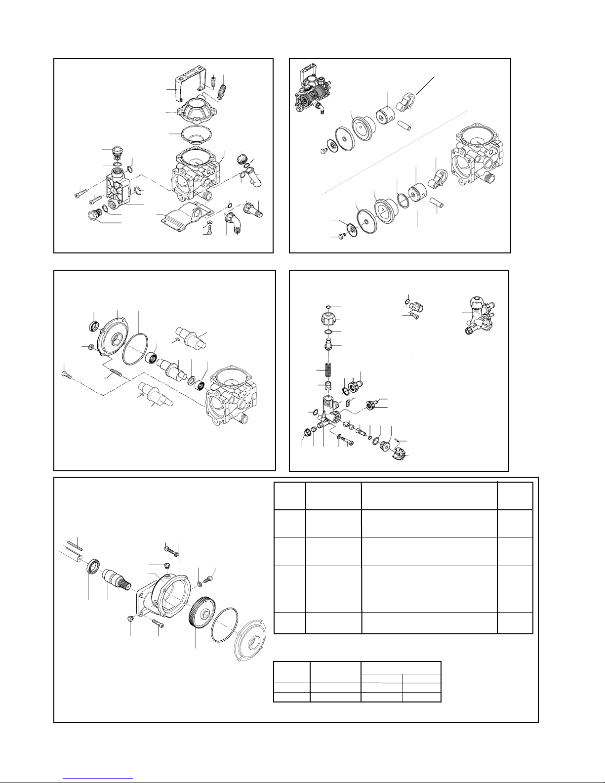
Models 9910-D252, D252GRGI, D252GRGI58, & D252GRGIAP
www.contree.com • 920-356-0121 • [email protected]
20
65
67
68
28
27
53
59
60
22
58
43
26
52
31
51
54
49
113
12
24
125
126
23
15
17
64
63
61
108
37
36
62
33
104
37
127
34
38
GRGI Models only
57
56
22
70
22
124
126
112
125
6
5
16
107
97
107
111
110
8
7
21
48
32
To serial number 010501
25
19
18
30
20
From serial number 010602
22
105
106
The 9910-KIT1990 control
unit includes washer (41)
and bolts (42).
50
35
22
45
109
96
104
Figure 27
101
35
39
40
41
42
Ref. Part
No. Number Description Qty.
4 9910-620301 Plug 2
5 9910-800380 O-Ring 1
12
41
4
102
4
105
106
80
103
5
12 9910-850850 M6 x 30 Bolt 4
41 9910-550331 Washer 4
80 9910-800280 Gear 1
96 9910-881090 Key 1
101 9910-800810 Driver Gear, 3/4” shaft only 1
101 9910-801230 Driver Gear, 5/8” shaft only 1
102 9910-800820 Gearbox 1
103 9910-800800 M8 x 16 Locating Bolt 1
104 9910-480820 Seal 1
105 9910-620440 5/16 24 UNF x 7/8 Bolt 4
106 9910-820520 Washer 1
Ref. No. Description Tightening Torque
In. Lbs. Nm
4 Plug 87.5 9.8
105 Bolt 175.0 19.6
47
46
Page 21
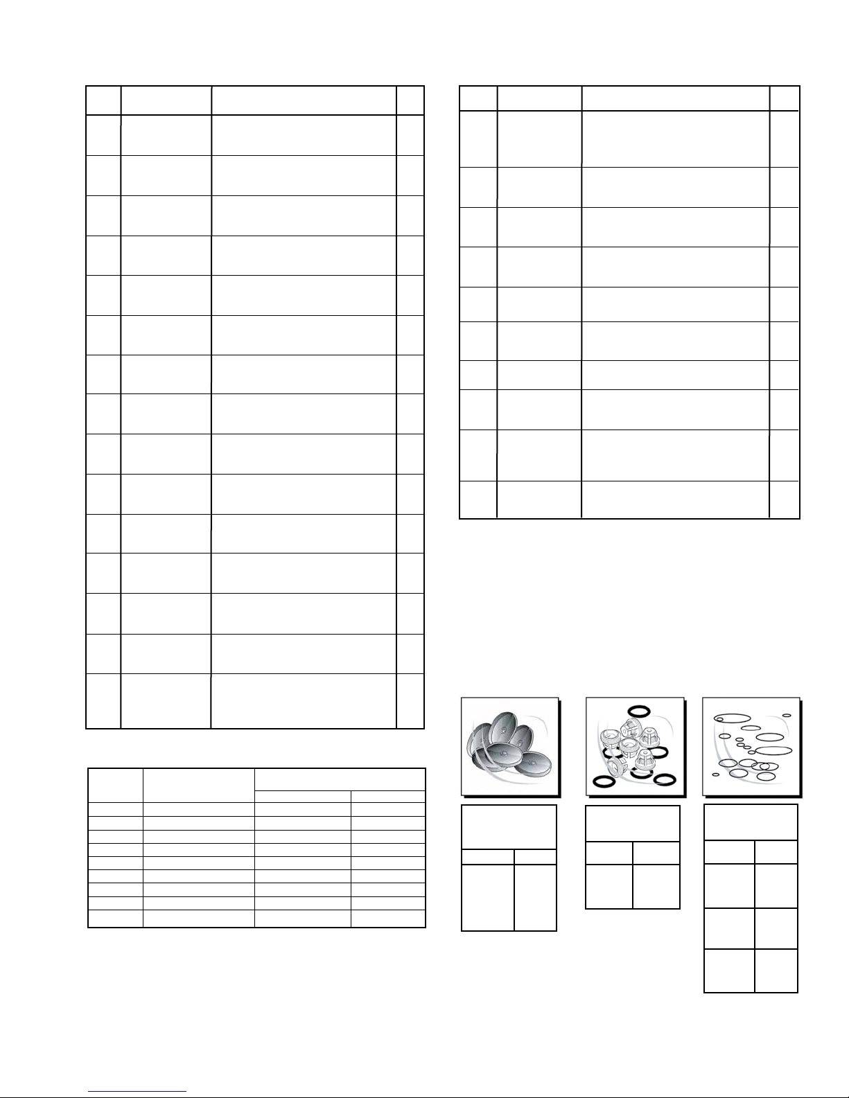
Models 9910-D252, D252GRGI, D252GRGI58, & D252GRGIAP
www.contree.com • 920-356-0121 • [email protected]
21
Ref. Part
No. Number Description Qty.
53 9910-800380 O-Ring 1
6 9910-800020 Flange 1
7 9910-800172 3/4˝ SolidShaft 1
8 9910-800160 Spacer 1
12 9910-390440 Nut 4
15 9910-800200 Seal 1
16 9910-800180 Roller Bearing 1
17 9910-550330 Stud 4
18 9910-802070 Piston 2
19 9910-800140 Connecting Rod 2
20 9910-800130 Piston Pin 2
21 9910-480370 Roller Bushing 1
1,3
22
9910-480440 O-Ring 5
23 9910-680360 M8 x 50 Bolt 1
24 9910-800220 M8 x 45 Bolt 7
25 9910-800120 Piston 2
26 9910-800110 Sleeve 2
27 9910-800090 Retaining Bolt 2
28 9910-800350 Plate 2
30 9910-802080 Piston Ring 2
311 9910-800085 Diaphragm Desmopan (Std.) 2
31 9910-80008T Diaphragm Teflon (Opt.) 1
31 9910-800080 Diaphragm Buna (Opt.) 2
32 9910-802050 Sleeve 2
333 9910-740290 O-Ring 1
34 9910-801960 Oil Sight Glass 1
35 9910-800520 Ring Nut 2
363 9910-390180 O-Ring 1
37 9910-550450 Ring Nut 1
38 9910-800340 Hose Barb (Inlet) 3/4” 1
39 9910-800540 Plug 1
40 9910-800400 Valve Body 1
41 9910-550331 Washer 2
42 9910-801080 M6 x 40 Bolt 2
43 9910-800430 Valve 1
45 9910-800500 Ring Nut 1
46 9910-800510 Knob 1
47 9910-390330 Pin 1
483 9910-800560 O-Ring 1
49 9910-800490 Positioning Rod 1
50 9910-800530 Hose Barb (Outlet) 3/8” 1
51 9910-800670 Hose Barb (Bypass) 5/8” 1
52 9910-800680 Ring Nut 1
533 9910-740290 O-Ring 1
54 9910-800480 ATM Scale Adhesive 1
56 9910-800440 Lower Spring Guide 1
Ref. Part
No. Number Description Qty.
57 9910-800450 Spring 1
58 9910-800460 Upper Spring Guide 1
59 9910-800470 Adjustment Knob 1
60 9910-480550 Retaining Ring 1
61 9910-800010 Pump Body 1
62 9910-550057 Cap 1
631 9910-800190 Accumulator Diaphragm (Buna-N) 1
63 9910-80019T Accumulator Diaphragm (Teflon) 1
64 9910-809205 Upper Air Chamber 1
65 9910-800650 Valve 1
67 9910-540290 M8 x 25 Bolt 4
68 9910-800390 Handle 1
1,3
70
9910-800210 O-Ring 2
97 9910-800173 Thru-Shaft AP, 5/8” 1
104 9910-550460 Elbow 2
105 9910-800691 Flange, 1/2” NPT 1
106 9910-880280 M6 x 18 Bolt 2
107 9910-800590 Key 1
108 9910-800171 Shaft “GR-Version,” 3/4” 1
109 9910-Kit 1990 Control unit 1
110 9910-180431 M8 x 16 Bolt 2
111 9910-380241 Washer 2
112 9910-800311 Pulley Base 1
113 9910-320350 M6 x 12 Bolt 4
124 9910-801940 Head 2
2
125
9910-809060V Valve Assembly 4
2,3
126
9910-880830 O-Ring 4
1273 9910-550040 O-Ring 1
1
Denotes Diaphragm Kit 9910-KIT1723
2
Denotes Valve Kit 9910-KIT2408
3
Denotes O-Ring Kit 9910-KIT2409
Ref. No. Description Tightening Torque
In. Lbs. Nm
23 Bolt 175.0 19.6
24 Bolt 175.0 19.6
27 Retaining Bolt 175.0 19.6
42 Bolt 87.5 9.8
67 Bolt 200.8 22.5
106 Bolt 87.5 9.8
110 Bolt 175.0 19.6
113 Bolt 87.5 9.8
125 Valve Assembly 131.2 14.7
9910-KIT1723
Diaphragm Kit
Desmopan
Ref. No. Qty.
22 2
311 2
631 1
70 2
9910-KIT2408
Valve Kit
Ref. No. Qty.
125 4
126 4
9910-KIT2409
O-Ring Kit
Ref. No. Qty.
5 1
22 5
33 4
36 1
48 1
53 1
70 1
126 4
127 1
Page 22
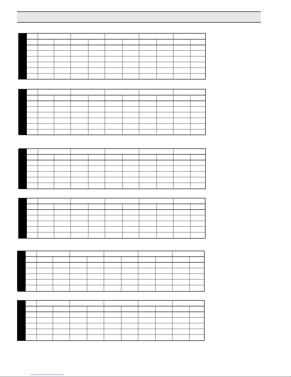
Performance Charts
www.contree.com • 920-356-0121 • [email protected]
22
U.S. Units
450 RPM 500 RPM 550 RPM 600 RPM 650 RPM
PSI GPM HP GPM HP GPM HP GPM HP GPM HP
0 4.8 0.15 5.4 0.19 5.9 0.23 6.1 0.25 6.5 0.27
72 4.1 0.33 4.6 0.37 5.0 0.42 5.5 0.45 5.9 0.46
145 4.0 0.49 4.4 0.57 4.8 0.64 5.3 0.65 5.6 0.72
217 3.9 0.66 4.3 0.76 4.7 0.82 5.2 0.89 5.5 0.97
Series D252
290 3.8 0.84 4.2 0.94 4.6 1.02 5.1 1.12 5.4 1.21
363 3.7 0.90 4.1 1.01 4.5 1.11 5.0 1.20 5.3 1.31
Metric Units
450 RPM 500 RPM 550 RPM 600 RPM 650 RPM
BAR LPM HP LPM HP LPM HP LPM HP LPM HP
0 18.0 0.15 20.5 0.19 22.4 0.23 23.1 0.25 24.6 0.27
5 15.3 0.33 17.3 0.37 18.7 0.42 20.8 0.45 22.2 0.46
10 14.9 0.49 16.6 0.57 18.1 0.64 19.8 0.65 21.3 0.72
15 14.7 0.66 16.4 0.76 17.9 0.82 19.6 0.89 20.9 0.97
20 14.5 0.84 16.0 0.94 17.4 1.02 19.4 1.12 20.5 1.21
Series D252
25 14.1 0.90 15.6 1.01 17.2 1.11 19.0 1.20 20.2 1.31
U.S. Units
350 RPM 400 RPM 450 RPM 500 RPM 550 RPM
PSI GPM HP GPM HP GPM HP GPM HP GPM HP
0 6.1 0.13 6.9 0.16 7.8 0.19 8.7 0.24 9.6 0.28
145 5.7 0.55 6.6 0.66 7.2 0.76 8.1 0.85 9.3 0.90
290 5.6 1.00 6.3 1.14 7.1 1.29 7.8 1.47 8.8 1.64
Series D30
465 5.5 1.46 5.9 1.67 6.9 1.89 7.7 2.06 8.6 2.27
580 5.2 1.90 5.8 2.11 6.8 2.41 7.5 2.71 8.3 2.94
Metric Units
350 RPM 400 RPM 450 RPM 500 RPM 550 RPM
BAR LPM HP LPM HP LPM HP LPM HP LPM HP
0 23.0 0.13 26.1 0.16 29.5 0.19 32.8 0.24 36.2 0.28
10 21.4 0.55 24.9 0.66 27.3 0.76 30.6 0.85 34.9 0.90
20 21.0 1.00 23.7 1.14 26.7 1.29 29.5 1.47 33.4 1.64
Series D30
30 20.6 1.46 22.4 1.67 26.0 1.89 29.0 2.06 32.5 2.27
40 19.5 1.90 22.1 2.11 25.8 2.41 28.2 2.71 31.4 2.94
NOTE:
“HP” is electrical
horsepower.
Consult your gas
engine supplier
for engine
horsepower
required.
U.S. Units
350 RPM 400 RPM 450 RPM 500 RPM 550 RPM
PSI GPM HP GPM HP GPM HP GPM HP GPM HP
0 9.7 0.36 11.9 0.49 12.3 0.64 13.2 0.77 14.8 0.94
145 9.3 1.08 11.5 1.25 11.9 1.49 12.9 1.59 14.6 1.76
290 9.1 1.85 11.0 2.09 11.7 2.40 12.6 2.72 14.5 2.97
Series D50
465 8.8 2.61 10.8 3.00 11.6 3.41 12.0 3.80 14.4 4.03
580 8.6 3.44 10.3 3.77 11.4 4.38 11.9 4.92 14.1 5.17
Metric Units
350 RPM 400 RPM 450 RPM 500 RPM 550 RPM
BAR LPM HP LPM HP LPM HP LPM HP LPM HP
0 36.8 0.36 45.0 0.49 46.6 0.64 49.9 0.77 55.8 0.94
10 35.1 1.08 43.3 1.25 44.9 1.49 48.6 1.59 55.1 1.76
20 34.4 1.85 41.5 2.09 44.1 2.40 47.4 2.72 54.9 2.97
Series D50
30 33.2 2.61 40.6 3.00 43.6 3.41 45.3 3.80 54.4 4.03
40 32.5 3.44 38.9 3.77 42.9 4.38 44.7 4.92 53.3 5.17
Page 23

Limited Warranty on Hypro/SHURflo Agricultural Pumps & Accessories
www.contree.com • 920-356-0121 • [email protected]
Hypro/SHURflo (hereafter, “Hypro”) agricultural products are warranted to be free of defects in material and workmanship under
normal use for the time periods listed below, with proof of purchase.
- Pumps: one (1) year from the date of manufacture, or one (1) year of use. This limited warranty will not
exceed two (2) years, in any event.
- Accessories: ninety (90) days of use.
This limited warranty will not apply to products that were improperly installed, misapplied, damaged, altered, or incompatible with
fluids or components not manufactured by Hypro. All warranty considerations are governed by Hypro’s written return policy.
Hypro’s obligation under this limited warranty policy is limited to the repair or replacement of the product. All returns will be tested
per Hypro’s factory criteria. Products found not defective (under the terms of this limited warranty) are subject to charges paid by the
returnee for the testing and packaging of “tested good” non-warranty returns.
No credit or labor allowances will be given for products returned as defective. Warranty replacement will be shipped on a freight
allowed basis. Hypro reserves the right to choose the method of transportation.
This limited warranty is in lieu of all other warranties, expressed or implied, and no other person is authorized to give any other
warranty or assume obligation or liability on Hypro’s behalf. Hypro shall not be liable for any labor, damage or other expense, ron
shall Hypro be liable for any indirect, incidental or consequential damages of any kind incurred
any defective product. This limited warranty covers agricultural products distributed within the United States of America. Other world
market areas should consult with the actual distributor for any deviation from this document.
Return Procedures
All products must be flushed of any chemical (ref. OSHA section 1910.1200 (d) (e) (f) (g) (h)) and hazardous chemicals must be
labeled/tagged before being shipped* to Hypro for service or warranty consideration. Hypro reserves the right to request a Material
Safety Data Sheet from the returnee for any pump/product it deems necessary. Hypro reserves the right to “disposition as scrap”
products returned which contain unknown fluids. Hypro re
chemical testing, and proper disposal of components containing unknown fluids. Hypro requests this in order to protect the environment and personnel from the hazards of handling unknown fluids.
serves the right to charge the returnee for any and all costs incurred for
by the reason of the use or sale of
Be prepared to give Hypro full details of the problem, including the model number, date of purchase, and from whom you purchased
your product. Hypro may request additional information, and may require a sketch to illustrate the problem.
Contact Hypro Service Department at 800-468-3428 to receive a Return Merchandise Authorization number (RMA#).
Returns are to be shipped with the RMA number clearly marked on the outside of the package. Hypro shall not be liable for freig t
damage incurred during shipping. Please package all returns carefully. All products returned for warranty work should be sent
shipping charges prepaid to:
HYPRO / PENTAIR
Attention: Service Department
375 Fifth Avenue NW
New Brighton, MN 55112
For technical or application assistance, call the Hypro Technical/Application number: 800-445-8360, or send an email to:
[email protected]. To obtain service or warranty assistance, call the Hypro Service and Warranty number:
800-468-3428; or send a fax to the Hypro Service and Warranty FAX: 651-766-6618.
*Carriers, including U.S.P.S., airlines, UPS, ground freight, etc., require specific identification of any hazardous material being shipped. Failure to do
so may result in a substantial fine and/or prison term. Check with your shipping company for specific instructions.
h
L-1382 Rev. D
Hypro 2015
Printed in USA
 Loading...