

Hypro 9303C, 9305C-HM3C, 9303C-SP, 9305C-HM3C-SP, 9304C Installation, Operation, Repair And Parts Manual
...Page 1
Series 9300 Hydraulically-Driven
Centrifugal Pumps
Form 325C
Installation, Operation, Repair and Parts Manual
Description
Hypro centrifugal pumps are designed for agricultural and
industrial spraying and transfer of a variety of fluids: water,
insecticides, herbicides, wettable powders, emulsives, liquid
fertilizers, etc. Polypropylene centrifugal pumps can also be
used to pump acid fertilizer, calcium chloride and other highly
corrosive liquids such as sulfuric and phosphoric acids.
02/00
Hypro Series 9300 hydraulic motor-driven centrifugal pumps
provide smooth performance. They can be conveniently
mounted on the tractor or sprayer, becoming part of the
vehicle’s hydraulic system and freeing the PTO for other uses.
The Hypro “close coupled” design reduces the mounting space
required, eliminating long shafts and couplers between the
pump and motor.
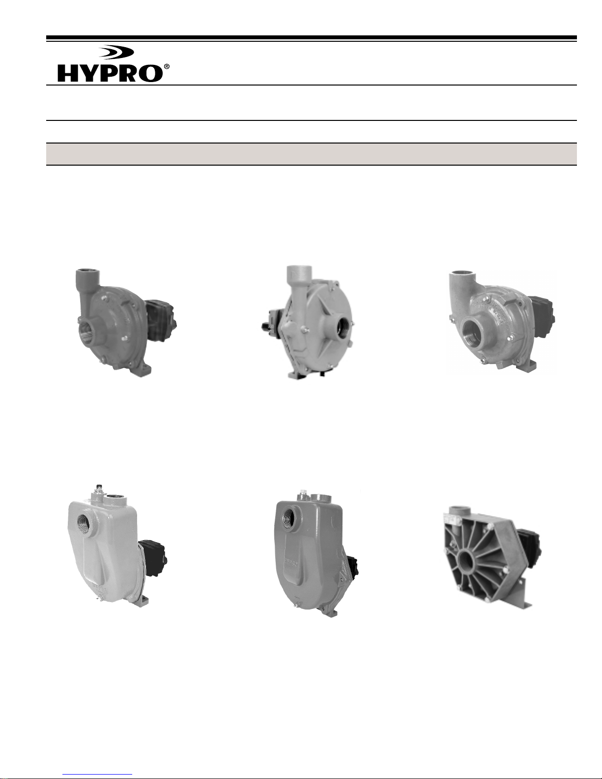
SERIES 9303C
Cast Iron Centrifugal Pump
Max. Flow Rate: ...................... 114 gpm
Max. Pressure: ......................... 180 psi
Ports:........................... 1-1/2" NPT Inlet
1-1/4" NPT Outlet
Hydraulic Ports: .............1/2" NPT Inlet
1/2" NPT Tank
SERIES 9303C-SP
Cast Iron Centrifugal Pump
Max. Flow Rate: ...................... 122 gpm
Max. Pressure: ......................... 120 psi
Ports:........................... 1-1/2" NPT Inlet
1-1/4" NPT Outlet
Hydraulic Ports: .............1/2" NPT Inlet
1/2" NPT Tank
SERIES 9305C-HM3C
Cast Iron Centrifugal Pump
Max. Flow Rate: ...................... 160 gpm
Max. Pressure: ......................... 120 psi
Ports:..................................2" NPT Inlet
1-1/2" NPT Outlet
Hydraulic Ports: .............1/2" NPT Inlet
1/2" NPT Tank
SERIES 9305C-HM3C-SP, BSP
Cast Iron Centrifugal Pump
Max. Flow Rate: ...................... 160 gpm
Max. Pressure: ......................... 120 psi
Ports:..................... 2" NPT or BSP Inlet
2" NPTor BSP Outlet
Hydraulic Ports: .............1/2" NPT Inlet
1/2" NPT Tank
SERIES 9304C
Cast Iron Centrifugal Pump
Max. Flow Rate: ...................... 190 gpm
Max. Pressure: ......................... 130 psi
Ports:..................................2" NPT Inlet
1-1/2" NPT Outlet
Hydraulic Ports: .............1/2" NPT Inlet
1/2" NPT Tank
SERIES 9303P
Polypropylene Centrifugal Pump
Max. Flow Rate: ........................ 90 gpm
Max. Pressure: ......................... 100 psi
Ports:........................... 1-1/2" NPT Inlet
1-1/4" NPT Outlet
Hydraulic Ports: .............1/2" NPT Inlet
1/2" NPT Tank
Page 2
General Safety Information
Notes are used to notify of installation, operation, or maintenance
information that is important but not safety related.
Caution is used to indicate the presence of a hazard, which will
or can cause minor injury or property damage if the notice is
ignored
Warning denotes that a potential hazard exists and indicates
procedures that must be followed exactly to either eliminate or
reduce the hazard, and to avoid serious personal injury, or
prevent future safety problems with the product.
Danger is used to indicate the presence of a hazard
that will result in severe personal injury, death, or property
damage if the notice is ignored.
Do not pump flammable or explosive fluids such as gasoline,
fuel oil, kerosene, etc. Do not use in explosive atmospheres.
The Pump should be used only with liquids compatible with the
Pump component materials. Failure to follow this notice can
result in severe personal injury and/or property damage and will
void the product warranty.
1. Do not pump at pressures higher than the maximum
recommended pressure.
o
2. Maximum liquid temperatures is 140
centrifugal pumps.
3. Disconnect power before servicing.
4. Release all pressure within the system before servicing any
component.
5. Drain all liquids from the system before servicing any
component. Flush with water.
6. Secure the outlet lines before starting the pump. An unsecured
line may whip, causing personal injury and/or property
damage.
7. Check hose for weak or worn condition before each use.
Make certain that all connections are tightly secured.
8. Periodically inspect the pump and the system components.
Perform routine maintenance as required (See Repair
Instructions).
9. Use only pipe, hose and fittings rated for the maximum psi
rating of the pump.
F for Series 9300
Hazardous Substance Alert
1. Always drain and flush pump before servicing or
disassembling for any reason.
2. Always drain and flush pumps prior to returning unit
for repair.
3. Never store pumps containing hazardous chemicals.
4. Before returning pump for service/repair, drain out
all liquids and flush unit with neutralizing liquid.
Then, drain the pump. Attach tag or include written
notice certifying that this has been done. It is illegal
to ship or transport any hazardous chemicals without
United States Environmental Protection Agency
Licensing.
10. Do not use these pumps for pumping water or other liquids
for human or animal consumption.
Never use your hand to check the condition of hydraulic
lines or hoses. If hydraulic fluid penetrates the skin, get
medical help immediately. Failure to get proper medical
help may result in loss of limb or life. The safest way to
check hydraulic lines or hoses is by holding a piece of
cardboard next to the hydraulic line or hose.
The sound pressure level of the Pump is 80dBA.
Observe all safety precautions when operating the Pump
within close proximity for extended periods of time by
wearing hearing protectors. Extended exposure to
elevated sound levels will result in permanent loss of
hearing acuteness, tinnitus, tiredness, stress, and other
effects such as loss of balance and awareness.
-2-
Page 3
General Information—Hydraulic Systems
Hydraulic Pumps
Hydraulic pumps come in two basic types:
• Constant displacement - which will continue to put out
its rated flow regardless of pressure, until the relief valve
bypasses the flow.
• Variable displacement - which will produce only the
flow needed by the implement until the total pump
output is reached. If less than the full pump output is
required, an automatic stroke control mechanism decreases the pump output to maintain a constant pressure and flow. The output varies according to demand.
Open Center
Spool Valve
In Neutral
Position
Figure 1
Spool Valves
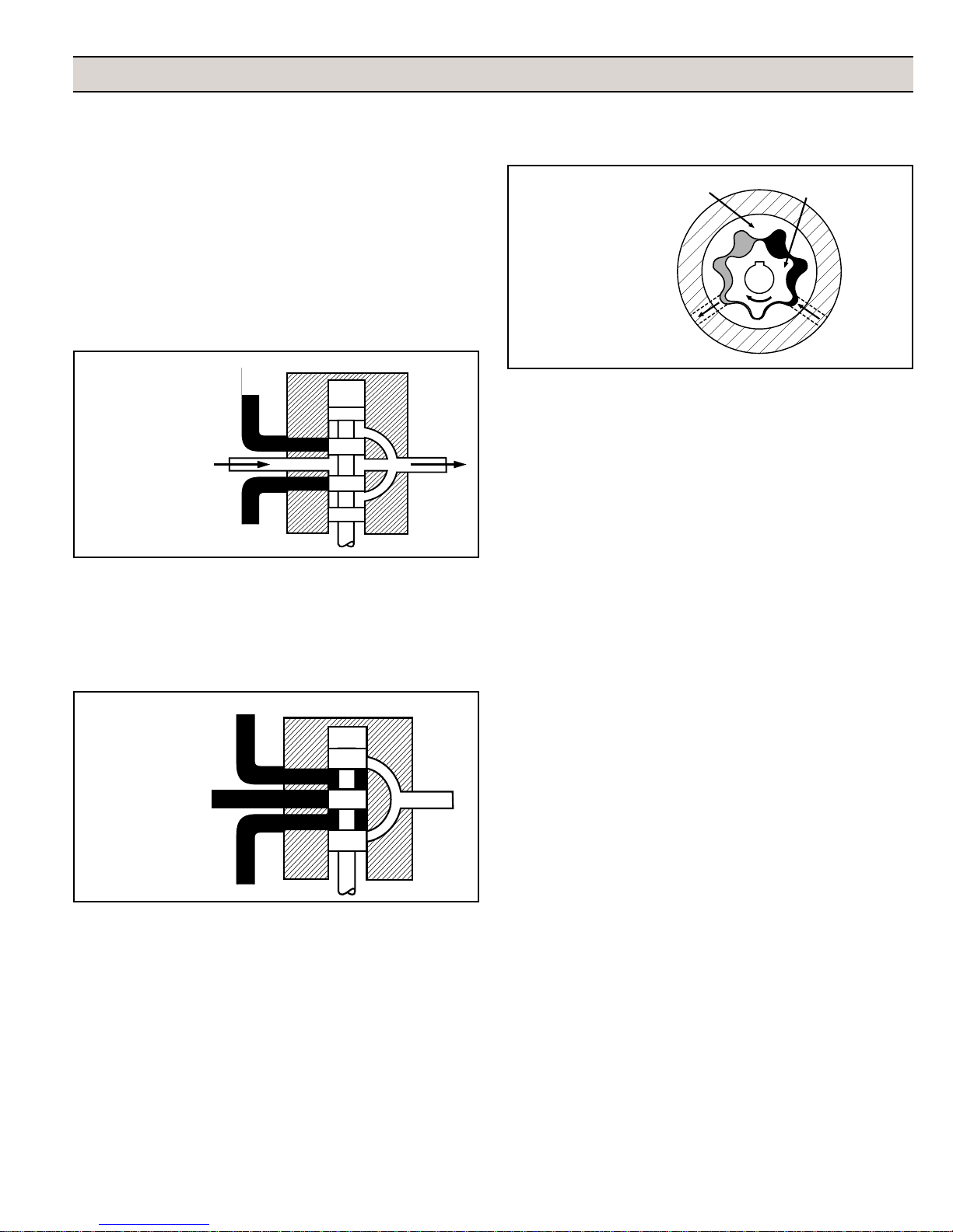
There are two basic types of spool valves used in conjunction
with these pumps — Open and Closed Center. In the Open
Center Valve (See Figure 1), the flow goes straight through the
valve when in the neutral position. This type is used for constant
displacement pumps where the flow should never be shut off.
Closed Center
Spool Valve
In Neutral
Position
Figure 2
Inner
Rotor
Gerotor Type
Rotor
Ring
Hydraulic Motor
InletOutlet
Figure 3
Low
Pressure
High
Pressure
Three Systems
Fitting these components together and installing a motor, we
have one of the three types of systems: Open Center, Closed
Center (pressure compensated) and Closed Center Load
Sensing (flow and pressure compensated).
Open Center Systems
In an Open Center System, the hydraulic pump puts out a
constant flow. If the pump puts out more oil than the motor can
use, a portion of the oil must be bypassed around the motor.
When the oil is bypassed around a loop and does no work, the
energy put into it by the pump turns into heat. Therefore, the
amount of oil bypassed should be kept to a minimum. Use the
largest motor possible.
Closed Center (Pressure Compensated) Systems
The Closed Center Pressure Compensated system has a
variable displacement pump which will deliver flow at the
necessary rate to maintain a specified pressure. It is desirable
to equip implements with a motor of a low flow range that will
cause the pump to operate between 1800 and 2100 psi [124
and 145 BAR]. A motor that requires a large volume to obtain
the correct implement speed usually causes the hydraulic
pump in a closed center system to operate at a lower pressure
than desirable. This low pressure results in unnecessary flow
and the generation of heat that lowers the lubricating quality of
the oil and can damage transmission parts. Use the smallest
motor possible.
The Closed Center Valve (See Figure 2) is used with variable
displacement pumps. The flow is completely shut off in the
neutral position, causing the pump stroke to adjust to zero flow.
The flow stops, but the pump maintains a static pressure up to the
valve.
Hydraulic Motors
Figure 3 shows an internal gear motor (Gerotor) where pressure causes the cavities between the gears to expand on one
side, developing torque. The Gerotor type of hydraulic motor is
used on Hypro pumps for its superior performance characteristics, including cooler running and higher rpm capabilities.
Closed Center Load Sensing Systems
(Flow and Pressure Compensating)
The Closed Center Flow Compensated System is a variation of
the pressure compensated system, designed primarily for
more efficient operation and the generation of less heat. It
works on the principle of maintaining a constant pressure drop
from the pump to the work port of the selector valve. Any
variation in demand at the motor will cause a change in flow.
The system senses this change in flow due to the change in
pressure drop across the valve, and causes the pump to
compensate by varying the pump flow. No restrictor is used in
the pressure line and no oil is bypassed.
-3-
Page 4
Installation Instructions
All Models — Open Center Systems
Models include Tank Port Adapter with built in Check Valve
Assembly and Pressure Port Adapter.
HM2C and HM4C Models Only — Closed Center and
Small Open Center Systems.
Models include Tank Port Adapter with built in Check Valve
Assembly and Pressure Port Adapter with three different
size metering orifices and HM4C models. Remove orifice for
use with closed center systems with flow control such as
John Deere closed center systems. Also remove for small
open center systems with a maximum flow of 8 gpm [30.28
lpm] for HM2C Model; 10 gpm [37.85 lpm] for HM4C Model.
If necessary, the pressure port adapter may be used without
a metering orifice installed in any closed center system,
provided the pressure differential across the hydraulic motor
does not exceed 1800 psi (12.4 Mpa).
Preliminary to Mounting
Consult the owners manual to determine the type and capacity
of the hydraulic system. Make sure the hydraulic system is
recommended to operate with a continuous load. Refer to the
Pump Selection Guide to confirm you have the proper pump for
your hydraulic system.
Check to see that the Pump Impeller can be turned by hand.
(Turn the shaft clockwise using a deep socket wrench on the
impeller nut.) If it cannot be turned, open the Pump Casing to
look for obstructions. Clean out any corrosion build up where
the casing fits over the eye of the Impeller.
The Inlet Line
To get the full capacity from the pump, the inlet line should be
the same size as the pump inlet port. A smaller size line can be
used to lower pump output, but the inlet line must be at least
one size larger than the outlet line. (Example: If the outlet line
is 3/4"[19 mm], use 1" [25.4 mm] inlet line.) The line must be
free of air leaks. Use good quality hose that cannot be
collapsed by suction. Relief valves are not normally
recommended to regulate spray pressure with centrifugal pumps.
Strainer Installation
While line strainers are recommended on the inlet side for roller
pumps, piston pumps and other positive displacement pumps,
the recommended placement of a strainer for a centrifugal
pump is in the outlet line. This will eliminate any possible
restriction that the strainer could create if it were installed in the
inlet side.
The best location in the discharge line is immediately after the
pump. The alternate location is in the inlet side if the strainer’s
capacity is adequate for the pump’s required flow. If the
strainer is installed in the inlet side, the strainer screen should
be checked regularly to prevent clogging that will result in
cavitation.
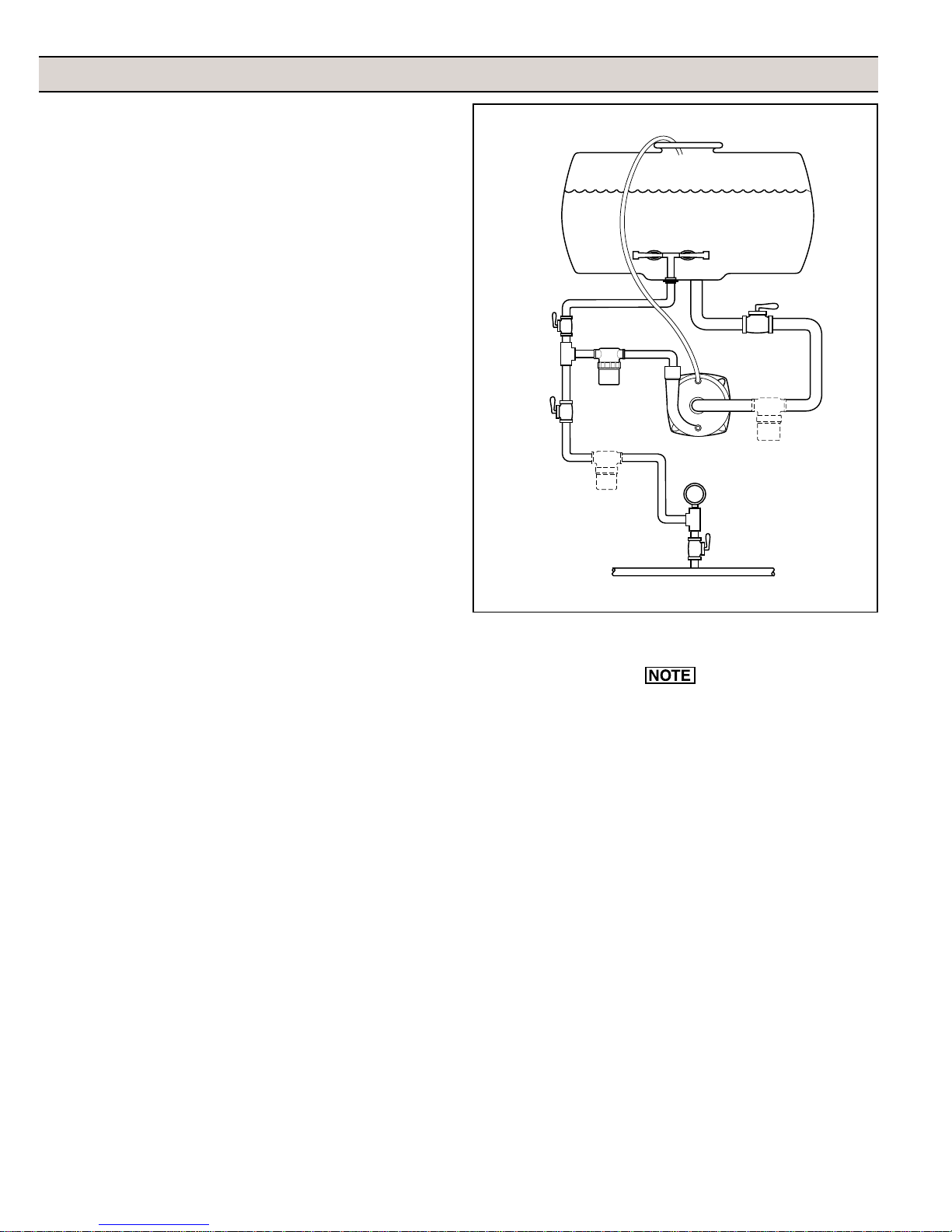
Plumbing Hook-up
Positive Vent Line
Vent
Line
Agitation
Line
Valve
Control
Valve
Figure 4
Line
Strainer
Line
Strainer
To Boom Nozzles or Spray Gun
Priming the Pump
The Pump must not be run dry.
Before starting the pump, the inlet line and pump must be filled
with liquid and all discharge lines must be open. On self-priming
models, only the pump chamber needs to be filled with liquid.
The pump must not be run unless it is completely filled with
liquid because there is a danger of damaging the mechanical
seal, which depends on the liquid for its lubrication.
Non-self-priming models should be mounted below the level of
the liquid. The suction line should slope down to the pump and
be free of dips and bends. If this cannot be done, a foot valve
should be installed in the end of the inlet line so that the line can
be completely filled with liquid before starting the pump.
For best priming results, the top vent plug should be removed
from the pump casing, and a vent line (1/4" [ 6.35 mm] tubing
is sufficient) should be installed running back to the top of the
tank. This line prevents air lock, and allows the pump to prime
itself by bleeding off trapped air. The small stream of liquid that
returns to the tank during operation is negligible. The discharge
from this line should be positioned in the tank above the high
liquid level. Self-priming models can be primed by removing the
top vent plug and filling the priming chamber. The priming
chamber will fill to the level of the inlet port. After use, the priming
Agitators
Shut-off Valve
Line
Strainer
Pressure
Gauge
Boom
Shut-off
Valve
-4-
Page 5
chamber should be flushed and drained to avoid chemical
corrosion and damage from freezing. Drain by removing the
lower drain plug.
Controlling the Pump Flow
The best way to control the flow is by incorporating two control
valves in a pipe tee immediately after the strainer in the
discharge line. This permits controlling agitation flow
independently of nozzle flow.
In any centrifugal pump, it is the large volume of liquid which
puts load on the drive. Use only the flow needed to develop the
pressure required at the boom and to maintain adequate
agitation. Hydraulic motor-driven centrifugal pumps are easily
adjusted to the exact flow required, as explained in the
Operating Instructions of this manual.
Hooking Up the Hydraulic Motor to the
Tractor Hydraulic System
Hypro Series 9300HMC hydraulic motor-driven pumps can be
mounted on either the tractor or sprayer. When hooking up,
make sure that no dirt or liquid gets into the hydraulic motor.
Keep all hydraulic connections clean. Be sure to connect
the hydraulic motor into the system correctly by putting the
pressure line to the Pressure Port Adapter and return line to the
Tank Port Adapter. The port adapters on the hydraulic motor
are sized to accommodate 1/2" NPT fittings. For maximum
performance, the hydraulic lines should also be at least 1/2"
[12.7 mm] in size. For lines longer than 8 feet [2.44 m] or for the
HM3C models, hydraulic line size should be at least 3/4" [19.05
mm] in order to reduce heat generation.
The tank (OUT) port adapter with a built-in check valve assembly
will guard against reverse operation — allowing you to reverse
oil flow to operate other equipment. This adapter must not be
removed. On HM2C and HM4C model pumps, the pressure
(IN) port adapter is a two-piece assembly consisting of an open
(unrestricted) adapter with three orifices packed loose with the
pump (See the Operations Section).
When using the HM2C or HM4C unit on any flow compensated
(load sensing) closed center system, or any small open center
system with a maximum flow of 8 gpm [30.28 lpm] for HM2C or
10 gpm [37.85 lpm] for HM4C, the metering orifice should be
removed from the pressure port adapter. When using these
units on flow compensated systems, connect to the motor
priority circuit if your tractor has one.
Standard spool valves, which are found on all tractor hydraulic
systems, can cause potentially damaging high peak pressures
in the hydraulic system when closed, because of abrupt shutoff of oil flow in both the supply and return lines. When shutting
off the pump, move the selector to the FLOAT position to allow
the centrifugal pump to come to a stop gradually.
Operation
Open Center Systems— All Models
Adjusting Centrifugal Pump Output
HM1C and HM3C motors have a bypass screw set 1-1/2
turns from fully closed at the factory. HM2C and HM4C
have the bypass screw fully closed from the factory.
1. Open the bypass adjustment screw 2-1/2 turns from fully
closed. Turn the bypass screw in to achieve the flow for
the desired gpm and psi.
2. Start the tractor. Leave the directional valve in the neutral
position and allow hydraulic oil to circulate for approximately 10 to 15 minutes or until adequately warmed.
4. Prime the centrifugal pump with all valves open (See the
Installation Instructions and System Configuration Diagram).
5. Close the agitation line valve and keep the control valve
and the boom shut-off valve open. Note the spray
pressure.
7. Open the agitation line valve until you have desired
circulation in the tank. Recheck the spray pressure. If it
is too low, close down the agitation line valve until the
desired spray pressure is reached. If the spray pressure
is too high, throttle the centrifugal pump by closing down
the control valve.
Closed Center (Pressure Compensated) —
HM2C and HM4C models only
On a pressure compensated system the amount of oil that is
allowed to flow through the hydraulic motor is regulated by a
metering orifice in the pressure port adapter. Three different
sizes of orifices are supplied with the HM2C and HM4C model
pumps to allow flexibility in the flow required for individual
sprayer needs.
The smaller the orifice the less hydraulic oil goes through the
motor, so the pump will run slower and the flow of liquid pumped
and the spray pressure will also be less. As the hydraulic oil flow
is increased (by installing a larger orifice), the amount of liquid
being pumped and the spray pressure is also increased.
Installing and Removing Metering Orifice
1. Shut off the hydraulic system.
2. Disconnect the line to the pressure port of the hydraulic
motor.
3. Remove the adapter from the motor using a 1-1/16''
wrench.
-5-
Page 6

4. Make sure the O-ring is on the metering orifice before
installing into port adapter.
5. The orifice is removed or installed in the port adapter by
tapping either in or out of the adapter.
A. To remove — tap the orifice out from the small end
of the adapter.
B. To install — tap the orifice in from the large end of
the adapter. The orifice is seated when a snap
sound is heard.
Adjusting Centrifugal Pump Output
1. Open the Bypass Adjusting Screw in the Hydraulic Motor
three (3) turns.
2. Start the tractor and allow the hydraulic oil to circulate for
approximately 10 to 15 minutes or until adequately warmed.
3. Close and lock down the bypass adjusting screw in the
hydraulic motor.
4. Prime the centrifugal pump with all valves open (See
Installation Instructions and System Configuration Diagram).
5. Close the agitation line valve and the control valve; open
the boom shut off valve.
6. With the pump running, open the control valve until the
pressure gauge indicates the desired spraying pressure.
7. Open the agitation line valve until sufficient agitation is
observed. Then, if spray pressure drops, readjust the
control valve to restore to the desire pressure.
8. If a sufficient boom pressure cannot be attained, install the
#2 size orifice and repeat Steps 5 through 7.
9. If a sufficient boom pressure still cannot be attained with
the #2 size orifice, install the #3 size orifice and repeat
Steps 5 through 7.
10. If a sufficient boom pressure still cannot be attained with
the #3 size orifice, remove the orifice and repeat Steps 5
through 7.
This system maintains a constant flow of hydraulic oil for a
given pressure drop. The flow is adjustable with a flow control
valve installed in the hydraulic system (Such as the Tortoise/
Hare control on John Deere tractors). Because this system
has adjustable flow, there is no need to bypass hydraulic oil as
in an open center system, or to restrict the flow with orifices as
in a closed center pressure compensated system.
Adjusting Centrifugal Pump Output
1. Make sure the orifice from the pressure port adapter of the
hydraulic motor has been removed (HM2C and HM4C
models only).
2. Close and lock down the bypass adjusting screw in the
hydraulic motor.
3. Set the tractor hydraulic flow control valve for minimum
hydraulic oil flow to the remote outlet (Tortoise position).
4. Start the tractor and allow the hydraulic oil to circulate for
approximately 10 to 15 minutes or until adequately warmed.
5. Prime the centrifugal pump with all valves open (See the
installation instructions and system configuration diagram).
6. Close the agitation line valve and open the control valve
and the boom shut-off valve.
7. Slowly adjust the tractor hydraulic flow control valve until
the desired boom pressure is attained.
8. Open the agitation line valve until sufficient agitation is
observed. If spray pressure drops, readjust the tractor
hydraulic flow control valve to restore it to the desire
pressure.
Flush Pump After Use
One of the most common causes for faulty pump performance is gumming or corrosion inside the pump. Flush the
pump and entire system with a solution that will chemically
neutralize the liquid pumped. Mix this solution according to
the manufacturer’s directions. This will dissolve most residue remaining in the pump, leaving the inside of the pump
clean for the next use.
To Prevent Corrosion
Closed Center (Load Sensing) — All Models
Many tractors are being introduced with load sensing systems
(also referred to as flow and pressure compensated systems)
which simplify system setup and eliminate many of the problems associated with using the wrong size pump motors on a
given hydraulic system. Usually, any of Hypro’s 9300HMC
models may be used on this type of system, provided the
hydraulic system produces sufficient oil flow for the hydraulic
motor being used (Refer to the Pump Selection Guide).
After cleaning the pump as directed above, flush it with a
permanent type automobile antifreeze (Prestone®, Zerex®,
etc.) containing a rust inhibitor. Use a 50% solution, half
antifreeze and half water, or fill the pump with FLUID FILM
and then drain it. A protective coating of FLUID FILM® will
remain on the inner pump surfaces. Save the excess FLUID
FILM® for the next application. Plug the ports to keep out air
during storage. For short periods of idleness, noncorrosive
liquids may be left in the pump, but air must be kept out.
Plug the ports or the seal port connections.
-6-
®
Page 7
Repair Instructions
Hypro Repair Tools:
Tool Box No. 3010-0168 • 1/4" Allen Wrench No. 3020-0008
Support Bars (2) No. 3010-0064 • Port Brush No. 3010-0066
1/16" Allen Wrench No. 3020-0009 • Brush Holder No. 3010-0067
• Large Retaining Ring Pliers No. 3010-0084 • Small Retaining Ring
Pliers No. 3010-0167
Shop Tools Needed
Bench Vice • Arbor Press • Air or Hand Drill • Small Knife
Metal Pipe — 1" dia. x 4" high (Bearing Seating Tool)
PVC Pipe — 3/4" dia. x 4" - 6" high (Seal Seating Tool)
12" Crescent Wrench • Two Flat Screwdrivers (approx. 10" Long)
1/2'', 9/16", 5/8" and 7/8" sockets • Hammer or Rubber Mallet
Small Screwdriver (recommended) • Large File (optional)
1/2" and 9/16" Box End Wrench • Lubricating Spray (WD-40 or LPS)
Small amount Hydraulic Oil • Cleaning Solvent Tank (recommended)
Pump Housing Disassembly
Instructions in italics describe procedures for the Series
9300P Polypropylene Centrifugal Pumps, when different
than the cast iron pumps.
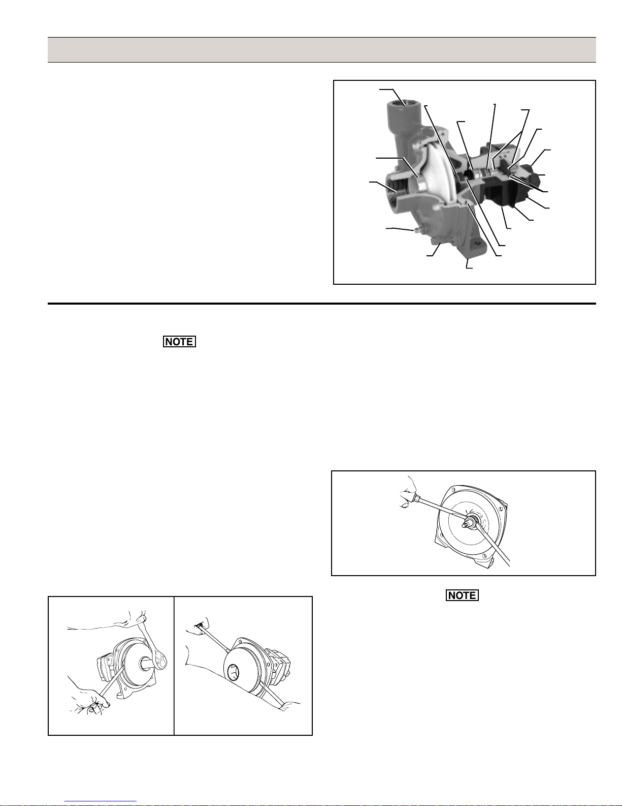
1. Using a 9/16" box end wrench, remove the four Hex Head
Bolts holding the Pump Casing to the Mounting Flange. (If
necessary, tap Pump Casing Outlet Port with rubber
mallet or hammer to separate.) [
remove the six bolts from the front. For the two bottom
bolts securing the Base, you will need to hold the two nuts
with another 1/2" wrench. Also remove the 5/16" screw
from the rear near the outlet port.
Using a 1/2" wrench,
]
Outlet Port
Shaft
Main
Seal
Mounting
Flange
Bearings
Motor
Body
Shaft
O-ring
Seal
Gerotor
Tank Port
Pressure Port
O-ring
Seal
Motor End
Gerotor
Housing
Adapter
Adapter
Plate
Ball
Bearing
] is removed, place a screwdriver
Stainless Steel
Wear Ring
Inlet Port
Drain/Vent
Plug
Figure 5
3. Once nut [
Mechanical
Seal
Pump
Casing
and washer
on each side behind the Impeller and pry away from the
Mounting Flange (See Figure 7). Remove Woodruff Key
from the Shaft. Remove O-ring from the Mounting Flange.
Pump Seal Removal
1. Lightly lubricate the Shaft for easier removal of the Seal.
Using two screwdrivers positioned opposite each other,
pry the rotary portion of the Seal from the Shaft (See
Figure 8).
2. To remove the Impeller Nut, insert a large screwdriver or
file (at least 10" [254 mm] long) into Impeller Vanes to
prevent Impeller from turning when loosening nut. Use a
5/8" socket wrench to remove the Impeller Nut by turning
it counterclockwise (See Figure 6). [
wrench to remove Plastic Seal Nut, then 9/16" deep socket
to remove Metal Jam Nut and Washer.
Figure 6
Figure 7
Use 7/8" deep socket
]
-7-
Figure 8
In the case of a severe Pump Seal leak, inspect the
Shaft/Bearing Assembly in the Hydraulic Motor for possible
contamination.
2. Using a 1/2'' box end wrench, remove the four bolts
holding the Motor to the Mounting Flange. Remove
Motor. [
Remove the Plastic Back Cover flange. Knock
the Seal out from back with a hammer and screwdriver.
Use a 1/2'' socket wrench and 1/2'' box end wrench to
remove the Mounting Flange from the Hydraulic Motor.
]
Page 8
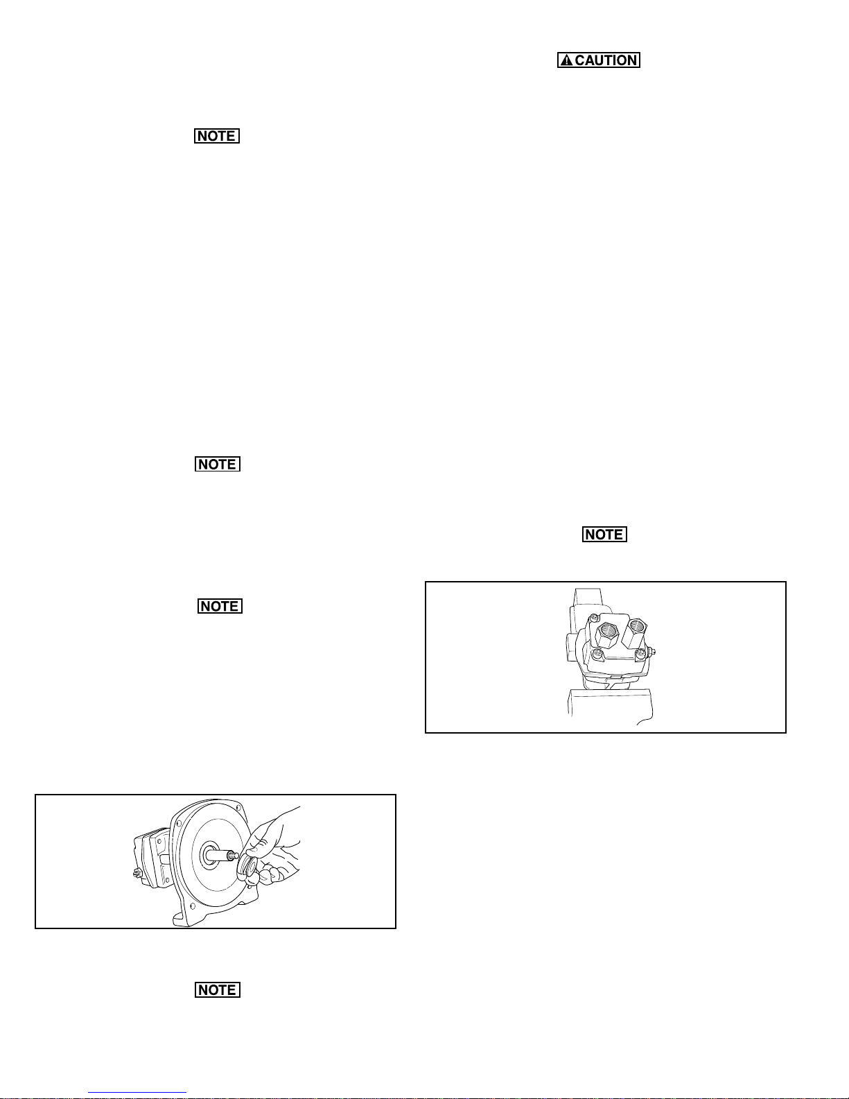
3. Using a screwdriver and hammer, tap out the stationary
portion of the Mechanical Seal from the Motor side of the
Mounting Flange. (If the Motor is not removed, the Seal
can be pried out with a small screwdriver.
The seal will be damaged by removal in this manner. A
new seal must be used when pump is reassembled.
Clean-Up Of Pump Housing
1. Using a circular bottle-type wire brush with air or hand drill,
clean the Outlet Port, Inlet Port and the sealing areas of the
O-ring on the Pump Casing and Mounting Flange. Using
the port brush, clean the seal cavity in the Mounting
Flange. [
9300P.
2. After wire brush cleaning, it is recommended that the
Pump Casing and Mounting Flange be further cleaned in
a solvent tank to remove rust and corrosion particles.
Seal Replacement/Pump Housing Reassembly
If the Hydraulic Motor requires repair, proceed to
Disassembly and Repair of the Hydraulic Motor.
1. Lubricate the seal cavity in the Mounting Flange with
WD-40®, LPS or equivalent. Do not lubricate the shaft.
2. Install the stationary portion of the Mechanical Seal by
sliding over the Shaft with the ceramic side out.
The last step should not be performed on the
]
The threads of the Plastic Seal Nut are fine and can be
easily cross threaded. To prevent cross threading, turn
the Plastic Seal Nut counter clockwise until area of thread
engagement is detected; then, turn the Plastic Seal Nut
clockwise until it is secure. Do not over tighten the Plastic
Seal Nut.
6. Insert a Woodruff Key into the Shaft key slot; then, place
the Impeller on the Shaft and align it with the Key and press
against the Mechanical Seal Assembly. Apply a blue
thread locking compound to the Impeller Nut and using a
5/8'' socket wrench and using a screwdriver to hold the
Impeller, install the Impeller Nut. [
On polypropylene
models insert the Woodruff Key into the Shaft key slot.
Place the Impeller on the Shaft and align it with the Key;
then, press against the Mechanical Seal Assembly. Place
the Metal Seal Washer on the Shaft. Apply a drop of blue
thread locking compound on the Impeller Nut and secure
the Impeller to the Shaft as described previously.]
7. Install the O-ring on the Mounting Flange. Replace the
O-ring if worn or damaged.
8. Place the pump casing on the mounting flange, insert and
tighten the bolts.
Disassembly and Repair of the Hydraulic Motor
The work area and Motor should be as clean as possible to
prevent contamination of parts.
Make sure both the seal cavity and seal are clean and
lubricated.
3. To seat the Seal in the seal cavity, use a piece of 3/4"
PVC pipe 4" to 6" [101.6 to 152.4 mm] in length. Lubricate sealing surface on seal after it is seated. Do not
lubricate the shaft.
4. To install the rotary portion of the mechanical seal, place
it over the shaft with the carbon side facing in, and press
against the stationary portion (See Figure 9).
Figure 9
5. Install rubber gasket 1700-0100 over shaft against rotary
portion of seal.
On Models 9305C-HM3C-SP, 9505C-HM3C-BSP, and
9305C-HM3C install the Washer on the Shaft prior to
installing the Impeller Nut.
Figure 10
1. Remove the Mounting Flange from the Motor body and
place Hydraulic Motor in vise (Figure 10).
2. Remove Tank Port Adapter and Pressure Port Adapter
with large crescent wrench or 1-1/16" box end wrench (See
Figure 10).
3. Using a 9/16" box end wrench, loosen the Nut on the
Bypass Adjusting Screw (See Figure 10).
4. Using a small screwdriver, remove the Bypass Adjusting
Screw from the Motor. (This will remove the Screw, Nut,
Washer and Thread-Seal Gasket.)
5. Using a 1/4" Allen wrench, remove the Socket Head Cap
Screws from the Motor End Plate (See Figure 10).
6. If Motor End Plate will not lift off easily, use a small
screwdriver to carefully pry apart the boss portion of the
End Plate and Gerotor Housing until free (See Figure 11).
If Gerotor Housing will not lift off easily, carefully pry apart
-8-
Page 9
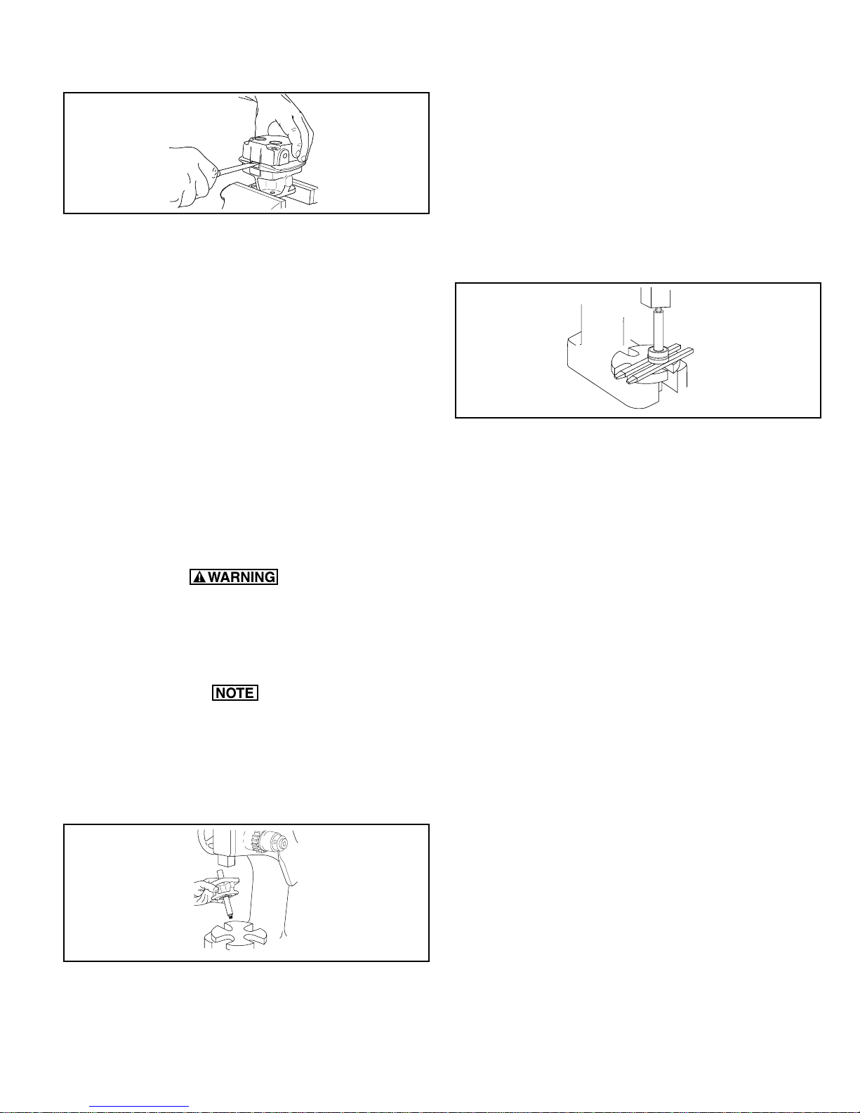
the boss area between the Gerotor Housing and the Motor
Body. (It may be necessary to alternate sides when prying
apart Motor sections.)
Figure 11
7. Remove both parts of the Gerotor.
8. On HM3C models, remove the Woodruff Key from the
Shaft. On HM1C, HM2C and HM4C models, remove the
Roll Pin from the Shaft.
9. Remove the O-ring from the Motor End Plate and Body with
a flat instrument such as a knife blade.
10. Inspect Motor End Plate, Body and Gerotor Housing for
wear and/or gouging. If gouging has occurred in both the
Motor End Plate and Body, the Motor is not repairable. If
gouging has occurred in the Motor End Plate, Body or
Gerotor Housing, the part that is worn must be replaced. If
Gerotor Housing is damaged, Gerotor parts must also be
replaced.
Hydraulic Motor Shaft Disassembly and Repair
1. Remove Large Retaining Ring from Shaft with a screwdriver. Remove Thrust Bearing Assembly from Shaft (includes the Thrust Bearing and two Thrust Bearing Races)
and the Seal Spacer.
2. Remove the Small Retaining Ring next to the Shaft Ball
Bearing.
3. To remove the Bearing from the Shaft, place the Shaft
(threaded end up) in the arbor press fixture. Place the two
support bars provided in the repair kit opposite each other
and between the Seal on the Shaft and the arbor press
fixture. Using an arbor press, press the Shaft through the
Bearing, Seal Spacer and Seal (See Figure 13).
Figure 13
4. Inspect the sealing area of the Shaft for wear. Inspect other
Shaft Assembly Components for wear and replace if
necessary.
To Remove the Shaft Assembly from the Motor Body
1. Remove the Slinger Ring from the Motor Shaft.
Special attention should be exercised when working with
retaining rings. Always wear safety goggles when working
with spring or tension loaded fasteners or devices.
2. Using the large retaining ring pliers, remove the Retaining
Ring next to the Ball Bearing in the Motor Body.
If Bearing is binding against the Retaining Ring so that it
cannot easily be removed, place the Motor Body (threaded
portion of the shaft up) and place on arbor press. Using a
piece of un-threaded metal pipe (1" dia. x 4" high [254. mm
x 101.6 mm high]), slide over the Shaft and gently press
down with the arbor press just enough to relieve the
pressure on the Retaining Ring.
5. While Motor is completely disassembled, clean all parts in
a solvent bath.
To Install New Shaft Seal
1. The sealing lips on a new Seal must be expanded to fit on
the Shaft. Press seal onto large end of Shaft with seal lip
facing out. Do not push Seal past keyway on Shaft.
2. Once seal lip has been expanded, remove the Seal from
the Shaft.
3. With the seal lip facing the large end of the Shaft, slide the
Seal over the threaded end of Shaft and gently push onto
the raised area of the Shaft, stopping approximately 1/4"
[6.35 mm] from the Large Retaining Ring groove.
4. Over the large end of the Shaft, install the Seal Spacer,
Thrust Bearing Race, Thrust Bearing, second Thrust Bearing Race and the Large Retaining Ring.
To Install Shaft Bearing
1. Over the threaded end of the Shaft, install the Spacer Ring
and the Ball Bearing.
Figure 12
3. Place Body in position on arbor press. Threaded portion
of the Shaft should be inside the fixture. Press out Shaft
assembly with arbor press (See Figure 12).
2. Insert the Shaft (threaded end down) into the arbor press
fixture. Place the two support bars opposite each other and
between the Bearing and the fixture. Place on an arbor
press and carefully press the Shaft down allowing just
enough room for the Retaining Ring next to the Bearing to
be installed.
-9-
Page 10
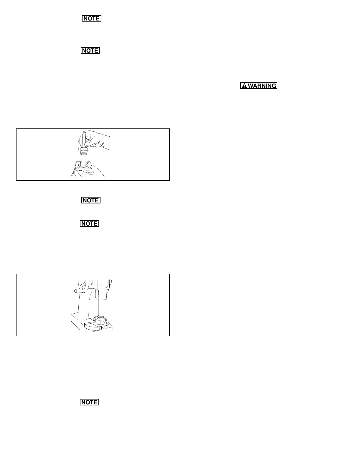
Make sure the Spacer ring between the seal and Bearing
is free floating (not binding).
Should the Main Needle Bearings in the Hydraulic Motor
need replacement, a new Body and/or End Plate, with the
Main Bearing already installed, must be used. If this
occurs, check other internal parts of the Motor for damage and wear.
To Install the Shaft Assembly in the Motor Body
1. Place the Shaft Assembly into the Motor Body bearing
bore with threaded end up (See Figure 14).
Figure 14
2. On arbor press, place Body on arbor press fixture.
Make sure the surface edge of the fixture is smooth and
clean.
An un-threaded piece of pipe (1" dia. x 4" [25.4 mm x 101.6
mm] high) is needed to support the outer bearing race on
the shaft ball bearing. Place this pipe over the shaft and
press shaft assembly down until retaining ring can be
installed in its groove in the bearing core of the motor body
(Figure 15).
Figure 15
Reassembly of Remaining Hydraulic Motor Parts
1. Place Motor Body in a vise with large end of Shaft facing up.
2. Install the O-ring in the Body.
3. Install the Woodruff Key or Roll Pin on the Shaft. Place the
Inner Gear of the Gerotor onto the Shaft making sure
Gerotor slot lines up with the key in the shaft.
4. Install the outer portion of the Gerotor, making sure the
Gerotor is centered within the O-ring groove on the Body.
5. Install the Gerotor Housing, making sure the pins in the
Gerotor Housing line up with their respective holes in the
Body.
6. Lightly lubricate the area between the Inner and Outer
Gerotor and the Outer Gerotor and Gerotor Housing with
hydraulic oil or mineral oil.
Special attention should be exercised when working with
retaining rings. Always wear safety goggles when working with spring or tension loaded fasteners or devices.
7. Install O-ring on the motor end plate.
8. Place end plate on gerotor housing, making sure holes in
end plate line up with pins in the gerotor housing.
9. Install four Socket Head Cap Screws in Motor End Plate
and, using a 1/4" Allen wrench, tighten Cap Screws alternately and evenly, in a crisscross pattern to approximately
15 foot pounds [ 20 Nm] of torque.
10. Install the Thread Seal Gasket on the Bypass Adjusting
Screw. Put the Gasket on from the slotted end and turn until
four threads on the Screw are showing. Install the Washer
and the Nut. Install Bypass Adjusting Screw in the Motor
end plate.
A. For closed center hydraulic systems, turn the Bypass
Adjusting Screw in until it bottoms out in the End Plate.
Tighten nut down with 9/16" box end wrench.
B. For open center hydraulic systems, turn the Bypass
Adjusting Screw in until it bottoms out in the End Plate;
then turn back out 1
1
⁄2 full turns. Holding the Bypass
Adjusting Screw with a screwdriver, tighten Nut. (Motor
will then have to be readjusted to tractor system.)
11. Replace O-ring on both port adapters.
12. Install Pressure Port Adapter and Tank Port Adapter back
onto the Motor. (For ease of installation, tighten the Pressure Port Adapter first, then the Tank Port Adapter.)
13. Remove Hydraulic Motor from the vise. Turn Shaft by hand
to check for binding.
14. Install Slinger Ring over Motor Shaft.
15. Install Motor into Pump Mounting Flange. Insert four Hex
Head Bolts; then, alternately and evenly tighten them.
[For
polypropylene models secure the Hydraulic Motor to the
Mounting Flange with four Hex Head Cap Screws and
Nuts. The Nuts should be visible when the assembly is
complete.]
The Woodruff Key can slide up behind the Inner Gear of the
Gerotor when the Gear is installed. Make sure the Key is
visible in the slot after the Gear is in place.
-10-
Page 11

Troubleshooting
If the proper Hydraulic Pump Unit has been selected according to Hypro recommendations, and the unit has been correctly plumbed into the hydraulic system, operation should be
quite satisfactory. If spraying performance is unsatisfactory or
hydraulic system heat is excessive etc., check the following
troubleshooting guide for possible problems and solutions.
Troubleshooting Guide
Symptom Probable Cause(s) Corrective Action(s)
Low Discharge Pump not primed. — Remove topmost vent plug from face of pump and runpump to expel
trapped air (See Installation Instructions).
Air leaks in inlet line. — Check and reseal inlet fittings.
Blocked or clogged line strainer. — Inspect strainer and clear any debris from screen.
Impeller plugged. — Inspect and clear obstruction.
Undersize inlet line or — Suction line should be the same diameter as inlet port of pump or larger.
collapsed hose.
Improperly sized hydraulic motor. — Refer to Pump Selection Guide to determine proper size
hydraulic motor for your hydraulic system.
Bypass Adjustment Screw not — Adjust bypass screw on side of hydraulic motor
set properly. in until the desired output is attained.
Eye of impeller rubbing on volute. — Remove volute (front cover) and inspect the impeller.
If wear detected, sand the impeller eye O.D. with emery cloth.
Hydraulic system Improper hydraulic motor size. — Refer to Pump Selection Guide to determine proper size for
overheating your hydraulic system.
Bypass Adjustment Screw — Close adjustment screw on side of hydraulic motor
set to bypass too much oil. to lessen the amount of oil being bypassed.
Improper metering orifice — Install proper size orifice. Refer to Installation section for proper sizing.
installed in pressure port. .
Insufficient hydraulic hose size. — Check hydraulic hose size. Hose should be at least 1/2" [12.7 mm]. For
large open-center systems 3/4" [19.05 mm].
-11-
Page 12
A
R
B
A
R
A
R
B
A
R
A
R
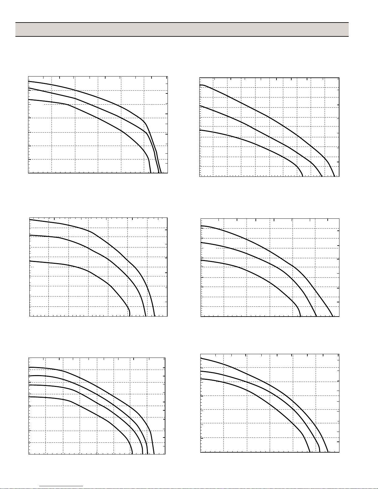
Performance Graphs
GRAPHS FOR HYDRAULICALLY-DRIVEN CENTRIFUGALS
9303C-HM1C
0 50 100 150 200 250 300 350 400 450
140
13GPM
120
12GPM
11GPM
100
L/min
P
80
S
I
60
40
20
0
0 20 40 60 80 100 120
GPM
9303C-HM3C
0 100 200 300 400 500
100
20 GPM
90
80
18 GPM
70
P
60
S
15 GPM
50
I
40
30
20
10
0
0 20 40 60 80 100 120 140
L/min
GPM
9303C-HM5C
0 100 200 300 400 500 600
160
140
120
100
P
S
80
I
60
40
20
0
0 20 40 60 80 100 120 140 160
16GPM
15GPM
14GPM
13GPM
L/min
GPM
9303C-HM2C
L/min
0 50 100 150 200 250 300 350
9
8
7
6
5
4
3
2
1
0
100
90
6GPM
80
70
5GPM
60
50
I
4GPM
40
30
20
10
0
02040608070503010 10090
6
5
B
4
3
2
1
0
GPM
9303C-HM4C
L/min
0 50 100 150 200 250 300 350
100
6
5
4
3
2
1
0
90
7GPM
80
70
6GPM
60
5GPM
50
I
40
30
20
10
0
0 20 40 60 80 100 120
6
5
B
4
3
2
1
0
GPM
9303P-HM1C
0 50 100 150 200 250 300 350 400 450
11
10
9
8
7
B
A
6
R
5
4
3
2
1
0
140
13GPM
120
12GPM
100
11GPM
P
80
S
I
60
40
20
0
0 20 40 60 80 100 120
L/min
9
8
7
6
B
5
4
3
2
1
0
GPM
-12-
Page 13
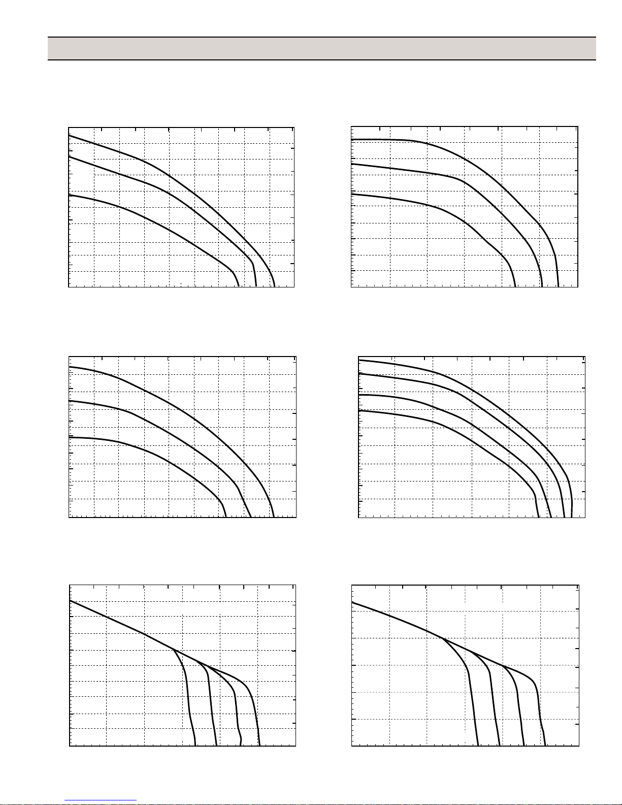
Performance Graphs
B
A
R
B
A
R
9303P-HM2C
0 50 100 150 200 250 300
100
90
7GPM
80
6GPM
70
P
60
S
5GPM
50
I
40
30
20
10
0
02010 4030 50 60 70 80 90
L/min
GPM
9303P-HM4C
L/min
0 50 100 150 200 250 300
90
80
6GPM
70
60
5GPM
P
S
50
I
40
4GPM
30
20
10
0
02040608070503010 90
GPM
9303P-HM3C
L/min
0 50 100 150 200 250 300 350
100
90
6
5
4
3
2
1
0
20 GPM
80
18 GPM
70
P
60
15 GPM
50
I
40
30
20
10
0
0 20 40 60 10060 120
6
5
4
3
2
1
0
GPM
9303P-HM5C
L/min
0 50 100 150 200 250 300 350 400 450
6
5
4
B
A
R
3
2
1
0
120
15 GPM
14 GPM
100
13 GPM
80
12 GPM
P
S
60
I
40
20
0
0 20 40 60 80 100 120
8
7
6
5
B
A
4
R
3
2
1
0
GPM
9303C-HM1C-SP Performance at 11 GPM
0 50 100 150 200 250 300 350 400 450
100
90
80
70
P
60
S
50
I
40
30
20
10
0
0 20 40 60 80 100 120
L/min
1-1/2˝ Inlet Hose
Feet of lift = 15 10
GPM
50
6
5
4
3
2
1
0
-13-
9303C-HM1C-SP Performance at 12 GPM
0 50 100 150 200 250 300 350 400 450
120
100
B
A
R
80
P
S
60
I
40
20
0
0 20 40 60 80 100 120
L/min
1-1/2˝ Inlet Hose
Feet of lift = 15 10
50
8
7
6
B
5
A
4
R
3
2
1
0
GPM
Page 14
B
A
R
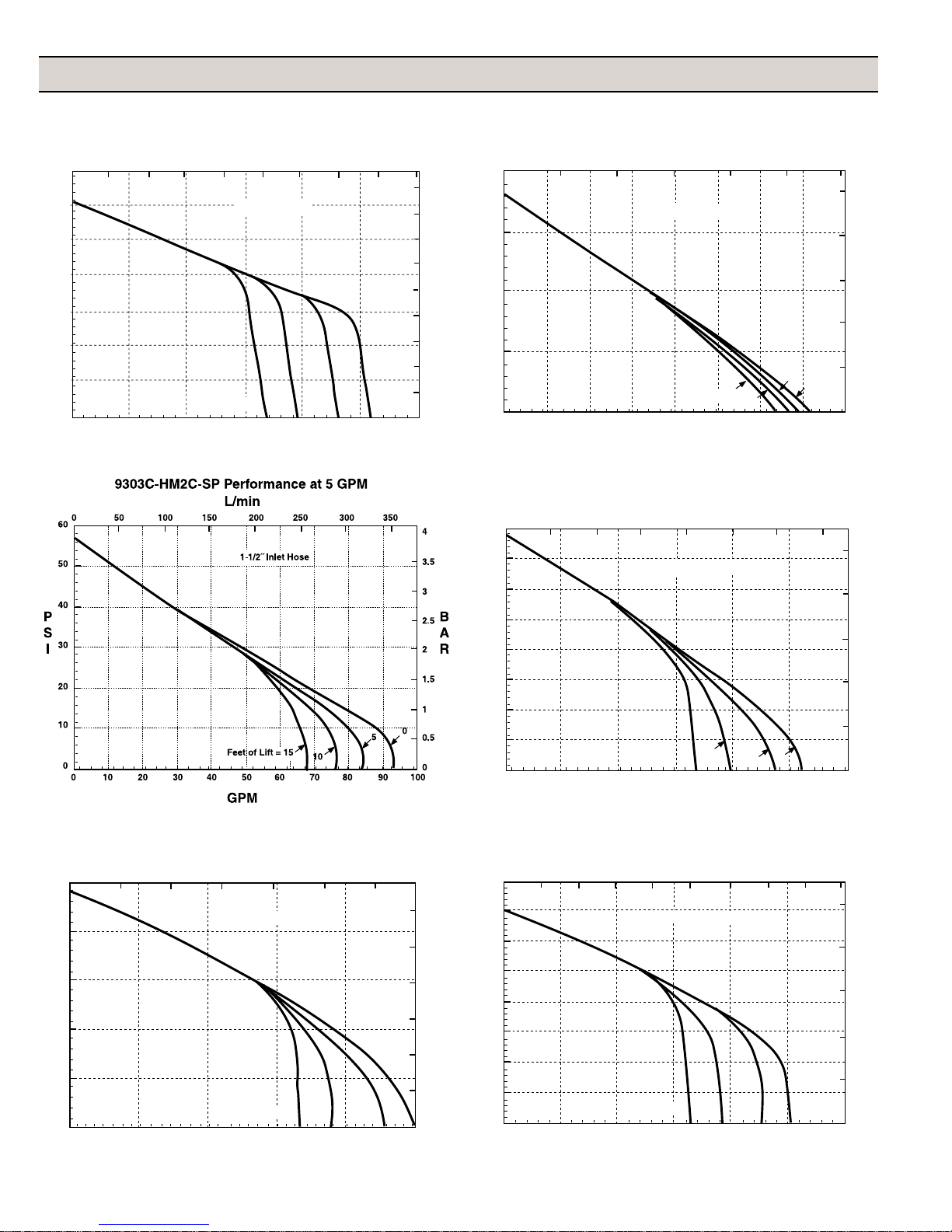
Performance Graphs
B
A
R
9303C-HM1C-SP Performance at 13 GPM
0 50 100 150 200 250 300 350 400 450
140
120
100
P
80
S
L/min
1-1/2˝ Inlet Hose
I
60
40
20
0
0 20 40 60 80 100 120
Feet of lift = 15 10
50
GPM
9303C-HM2C-SP Performance at 4 GPM
L/min
0 50 100 150 200 250 300
40
9
8
7
6
B
A
5
R
4
3
2
1
0
30
P
S
20
I
10
0
010 5060708030 4020
1-1/2˝ Inlet Hose
Feet of Lift = 15
5
10
2.5
2
B
A
1.5
R
1
0.5
0
0
GPM
9303C-HM2C-SP Performance at 6 GPM
L/min
0 50 100 150 200 250 300 350 400 450
80
70
60
50
40
I
30
20
10
0
0 60 80 100 1204020
1-1/2˝ Inlet Hose
Feet of Lift = 15
10
0
5
5
4
3
2
1
0
GPM
9303C-HM3C-SP Performance at 15 GPM
L/min
0 50 100 150 200 250 300 350
50
40
P
30
1-1/2˝ Inlet Hose
S
I
20
10
0
0 20 80 1006040
Feet of Lift = 15
10
GPM
9303C-HM3C-SP Performance at 18 GPM
L/min
0 50 100 150 200 250 300 350 450 450
80
3
2.5
2
1.5
1
0.5
5
0
0
70
60
50
P
S
40
I
30
20
10
0
0 20 80 100 1206040
1-1/2˝ Inlet Hose
Feet of Lift = 15
10
5
0
5
4
B
A
3
R
2
1
0
GPM
-14-
Page 15
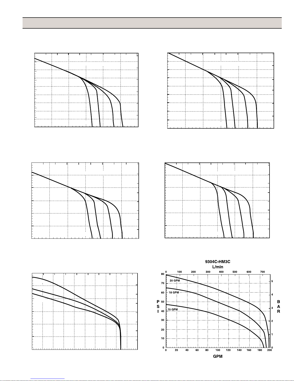
Performance Graphs
9303C-HM3C-SP Performance at 20 GPM
L/min
0 50 100 150 200 250 300 350 450 450
90
80
70
60
P
50
S
I
40
30
20
10
0
0 20 80 100 1206040
Feet of Lift = 15
1-1/2˝ Inlet Hose
10
5
GPM
9303C-HM5C-SP Performance at 14 GPM
L/min
0 50 100 150 200 250 300 350 400 450
120
100
80
1-1/2˝ Inlet Hose
P
S
60
I
9303C-HM5C-SP Performance at 13 GPM
L/min
0 50 100 150 200 250 300 350 400 450
6
5
4
B
A
R
3
2
1
0
0
90
80
70
60
1-1/2˝ Inlet Hose
P
50
S
I
40
30
20
10
0
020 8060 10040 120
Feet of Lift = 15 10 5 0
6
5
4
B
A
3
R
2
1
0
GPM
9303C-HM5C-SP Performance at 15 GPM
L/min
0 50 100 150 200 250 300 350 400 450
8
7
6
B
5
A
4
R
120
100
80
P
S
60
I
1-1/2˝ Inlet Hose
8
7
6
B
5
A
4
R
40
20
0
020 8060 10040 120
Feet of Lift = 15 10 5 0
GPM
9304C-HM1C
L/min
0 100 200 300 400 500 600 700 800 900
120
13 GPM
100
12 GPM
80
11 GPM
P
S
60
I
40
20
3
2
1
0
40
20
0
020 8060 10040 120
Feet of Lift = 15 10 5 0
3
2
1
0
GPM
8
7
6
B
5
A
R
4
3
2
1
0
0 150 200 25010050
GPM
0
-15-
Page 16
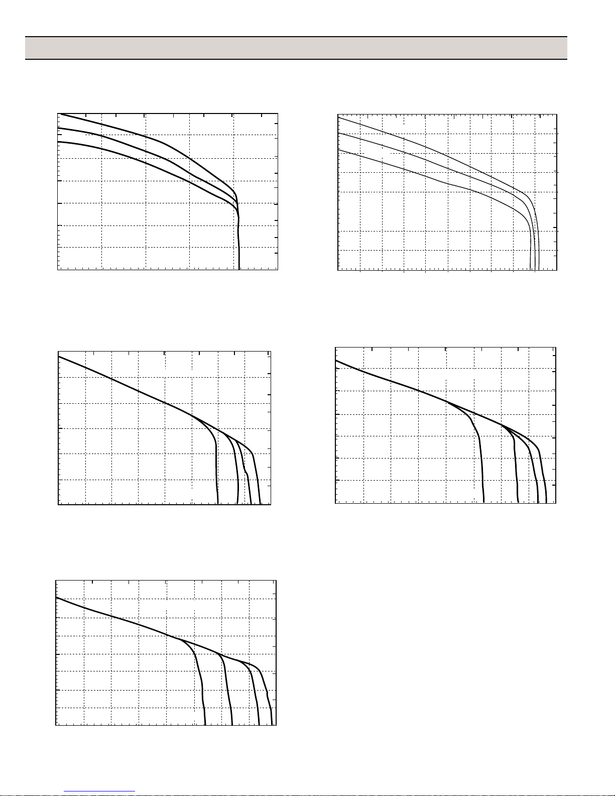
Performance Graphs
9304C-HM5C
L/min
0 100 200 300 400 500 600 700 800 900
140
17 GPM
120
16 GPM
15 GPM
100
P
80
S
I
60
40
20
0
0 150 200 25010050
GPM
9305C-HM3C-SP, BSP Performance at 17 GPM
L/min
0 100 200 300 400 500 600
120
100
80
P
S
60
I
40
20
0
0 20 100 120 140 16060 8040
2˝ Inlet Hose
Feet of Lift = 15
GPM
9305C-HM3C
0 100 200
9
8
7
6
B
A
5
R
4
3
2
1
0
160
140
120
P
100
19 GPM
18 GPM
17 GPM
S
80
I
60
40
20
0
0 20 40 60 80 100 120 140 160 180 200
L/min
300 400 500 600 700
GPM
11
10
9
8
7
B
6
A
R
5
4
3
2
1
0
9305C-HM3C-SP, BSP Performance at 18 GPM
L/min
0 100 200 300 400 500 600
140
8
7
6
B
5
A
R
4
3
2
10
1
5
0
0
120
100
P
80
S
I
60
40
20
0
0 20 100 120 140 16060 8040
2˝ Inlet Hose
Feet of Lift = 15
10
9
8
7
6
B
A
5
R
4
3
2
1
5
0
0
GPM
9305C-HM3C-SP, BSP Performance at 19 GPM
L/min
0 100 200 300 400 500 600
160
140
120
100
P
2˝ Inlet Hose
S
80
I
60
40
20
0
0 20 100 120 140 16060 8040
Feet of Lift = 15
GPM
10
8
B
A
6
R
4
2
5
10
0
0
-16-
Page 17
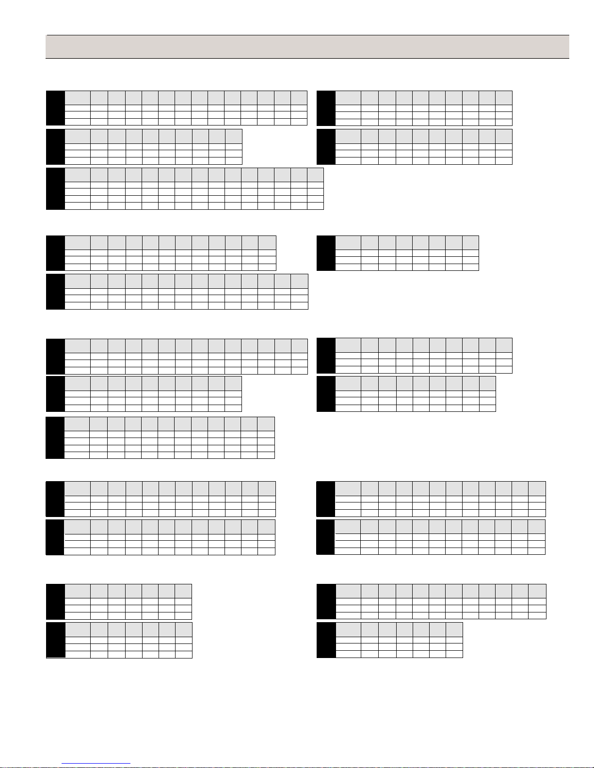
Performance Charts
Models 9303C-HM1C, 9303C-HM2C, 9303C-HM3C, 9303C-HM4C, & 9303C-HM5C
Hydraulic GPM at GPM at GPM at GPM at GPM at GPM at GPM at GPM at GPM at GPM at GPM at GPM at GPM at
Flow 10 PSI 20 PSI 30 PSI 40 PSI 50 PSI 60 PSI 70 PSI 80 PSI 90 PSI 100 PSI 110 PSI 120 PSI 130 PSI
11 GPM 105 104 101 96 90 82 71 60 47 31
12 GPM 112 110 109 107 105 101 92 81 67 53 36 9
13 GPM 114 112 111 109 107 104 102 96 85 76 63 33 13
9303C-HM1C
Hydraulic GPM at GPM at GPM at GPM at GPM at GPM at GPM at GPM at GPM at
Flow 10 PSI 20 PSI 30 PSI 40 PSI 50 PSI 60 PSI 70 PSI 80 PSI 90 PSI
15 GPM
100 92 83 69 47
18 GPM
116 114 108 100 90 76 55 33
20 GPM
9303C-HM3C
9303C-HM5C
125 123 120 114 107 96 85 71 50
Hydraulic GPM at GPM at GPM at GPM at GPM at GPM at GPM at GPM at GPM at GPM at GPM at GPM at GPM at GPM at
Flow 10 PSI 20 PSI 30 PSI 40 PSI 50 PSI 60 PSI 70 PSI 80 PSI 90 PSI 100 PSI110 PSI 120 PSI 130 PSI 140 PSI
13 GPM
120 118 113 105 97 86 73 59 44
14 GPM
133 131 128 123 116 108 98 88 74 61 44
15 GPM
139 138 135 132 126 119 110 100 89 77 66 50 20
16 GPM
147 146 145 142 137 132 126 117 107 95 83 70 55 37
Models 9304C-HM1C, 9304C-HM3C, & 9304C-HM5C
Hydraulic GPM at GPM at GPM at GPM at GPM at GPM at GPM at GPM at GPM at GPM at GPM at
Flow 10 PSI 20 PSI 30 PSI 40 PSI 50 PSI 60 PSI 70 PSI 80 PSI 90 PSI 100 PSI110 PSI
11 GPM
210 209 208 203 178 140 89 44
12 GPM
210 210 209 206 187 160 130 87 35
13 GPM
9304C-HM1C
9304C-HM5C
211 211 210 208 200 175 149 120 93 64 26
Hydraulic GPM at GPM at GPM at GPM at GPM at GPM at GPM at GPM at GPM at GPM at GPM at GPM at GPM at
Flow 10 PSI 20 PSI 30 PSI 40 PSI 50 PSI 60 PSI 70 PSI 80 PSI 90 PSI 100 PSI 110 PSI 120 PSI 130 PSI
15 GPM
206 206 205 205 205 195 170 145 119 85 40
16 GPM
206 206 205 205 205 204 188 165 143 120 87 49
17 GPM
206 206 205 205 205 204 200 184 168 150 128 96 52
Hydraulic GPM at GPM at GPM at GPM at GPM at GPM at GPM at GPM at GPM at
Flow 10 PSI 20 PSI 30 PSI 40 PSI 50 PSI 60 PSI 70 PSI 80 PSI 90 PSI
4 GPM
70 60 45 25
5 GPM
83 75 64 51 37 22 4
6 GPM
9303C-HM2C
Hydraulic GPM at GPM at GPM at GPM at GPM at GPM at GPM at GPM at GPM at
9303C-HM4C
Hydraulic GPM at GPM at GPM at GPM at GPM at GPM at GPM at
15 GPM
18 GPM
20 GPM
9304C-HM3C
94 89 81 72 62 50 37 22 7
Flow 10 PSI 20 PSI 30 PSI 40 PSI 50 PSI 60 PSI 70 PSI 80 PSI 90 PSI
5 GPM
84 76 66 52 34
6 GPM
97 92 86 78 67 50 25
7 GPM
110 104 98 91 82 69 55 38 14
Flow 10 PSI 20 PSI 30 PSI 40 PSI 50 PSI 60 PSI 70 PSI
180 158 122 72
189 185 164 140 99 49
197 193 190 182 154 110 63
Models 9303P-HM1C, 9303P-HM2C, 9303P-HM3C, 9303P-HM4C, & 9303P-HM5C
Hydraulic GPM at GPM at GPM at GPM at GPM at GPM at GPM at GPM at GPM at GPM at GPM at GPM at GPM at
Flow 10 PSI 20 PSI 30 PSI 40 PSI 50 PSI 60 PSI 70 PSI 80 PSI 90 PSI 100 PSI 110 PSI120 PSI 130 PSI
11 GPM
12 GPM
13 GPM
9303P-HM1C
Hydraulic GPM at GPM at GPM at GPM at GPM at GPM at GPM at GPM at GPM at
15 GPM
18 GPM
20 GPM
9303P-HM3C
Hydraulic GPM at GPM at GPM at GPM at GPM at GPM at GPM at GPM at GPM at GPM at GPM at
Flow 10 PSI 20 PSI 30 PSI 40 PSI 50 PSI 60 PSI 70 PSI 80 PSI 90 PSI 100 PSI110 PSI
13 GPM
14 GPM
15 GPM
9303P-HM5C
16 GPM
93 90 86 80 74 67 59 49 36 18
102 99 95 91 87 81 74 66 55 39 19
109 106 103 99 94 88 82 74 65 54 42 28 10
Flow 10 PSI 20 PSI 30 PSI 40 PSI 50 PSI 60 PSI 70 PSI 80 PSI 90 PSI
85 80 70 60 44
100 97 92 84 76 63 48
109 108 104 99 90 82 71 60 39
94 92 86 78 68 58 44 15
100 98 94 88 79 70 60 48 25
108 107 104 100 94 86 77 68 57 42
113 112 110 106 100 93 86 78 68 56 40
Hydraulic GPM at GPM at GPM at GPM at GPM at GPM at GPM at GPM at GPM at
Flow 10 PSI 20 PSI 30 PSI 40 PSI 50 PSI 60 PSI 70 PSI 80 PSI 90 PSI
5 GPM
65 56 46 38 20
6 GPM
74 72 64 56 48 38 21
7 GPM
9303P-HM2C5
Hydraulic GPM at GPM at GPM at GPM at GPM at GPM at GPM at GPM at
9303P-HM4C
80 75 70 62 57 48 40 28 9
Flow 10 PSI 20 PSI 30 PSI 40 PSI 50 PSI 60 PSI 70 PSI 80 PSI
5 GPM
60 52 41 26
6 GPM
70 66 58 48 37 21
7 GPM
80 76 70 63 55 45 32 15
Models 9303C-HM1C-SP at 0' Lift, 5' Lift, 10' lift, & 15' Lift
Hydraulic GPM at GPM at GPM at GPM at GPM at GPM at GPM at GPM at GPM at GPM at GPM at
Flow 10 PSI 20 PSI 30 PSI 40 PSI 50 PSI 60 PSI 70 PSI 80 PSI 90 PSI 100 PSI110 PSI
11 GPM
100 99 97 91 73 55 39 20
12 GPM
at 0´ Lift
9303C-HM1C-SP
Hydraulic GPM at GPM at GPM at GPM at GPM at GPM at GPM at GPM at GPM at GPM at GPM at
Flow 10 PSI 20 PSI 30 PSI 40 PSI 50 PSI 60 PSI 70 PSI 80 PSI 90 PSI 100 PSI 110 PSI
11 GPM
12 GPM
at 10´ Lift
13 GPM
9303C-HM1C-SP
101 100 99 98 94 79 62 47 32 14
13 GPM
102 101 100 99 98 94 79 62 48 33 20
77 75 74 73 71 55 39 20
77 76 74 73 72 71 62 47 32 14
77 76 74 73 72 71 70 62 48 33 20
Hydraulic GPM at GPM at GPM at GPM at GPM at GPM at GPM at GPM at GPM at GPM at GPM at
Flow 10 PSI 20 PSI 30 PSI 40 PSI 50 PSI 60 PSI 70 PSI 80 PSI 90 PSI 100 PSI 110 PSI
11 GPM
12 GPM
at 5´ Lift
13 GPM
9303C-HM1C-SP
Hydraulic GPM at GPM at GPM at GPM at GPM at GPM at GPM at GPM at GPM at GPM at GPM at
Flow 10 PSI 20 PSI 30 PSI 40 PSI 50 PSI 60 PSI 70 PSI 80 PSI 90 PSI 100 PSI110 PSI
11 GPM
12 GPM
at 15´ Lift
13 GPM
9303C-HM1C-SP
90 89 88 84 73 55 39 20
90 89 88 87 85 79 62 47 32 14
91 90 88 87 86 85 79 62 48 33 20
66 64 63 62 60 55 39 20
66 65 64 63 61 60 55 47 32 14
66 65 63 62 61 60 59 57 48 33 20
Models 9303C-HM2C-SP at 0' Lift, 5' Lift, 10' lift, & 15' Lift
Hydraulic GPM at GPM at GPM at GPM at GPM at GPM at
Flow 10 PSI 20 PSI 30 PSI 40 PSI 50 PSI 60 PSI
4 GPM
55 34 12
5 GPM
at 0´ Lift
9303C-HM2C-SP
Hydraulic GPM at GPM at GPM at GPM at GPM at GPM at
at 10´ Lift
9303C-HM2C-SP
88 68 49 28 11
6 GPM
100 89 76 60 46 31
Flow 10 PSI 20 PSI 30 PSI 40 PSI 50 PSI 60 PSI
4 GPM
52 33 12
5 GPM
74 61 46 28 11
6 GPM
77 74 68 58 46 31
Hydraulic GPM at GPM at GPM at GPM at GPM at GPM at GPM at GPM at GPM at GPM at GPM at
Flow 10 PSI 20 PSI 30 PSI 40 PSI 50 PSI 60 PSI 70 PSI 80 PSI 90 PSI 100 PSI 110 PSI
13 GPM
14 GPM
at 5´ Lift
15 GPM
9303C-HM5C-SP
Hydraulic GPM at GPM at GPM at GPM at GPM at GPM at
at 15´ Lift
9303C-HM2C-SP
90 89 88 85 76 59 40 21
90 89 88 87 85 78 61 43 27 10
90 89 88 87 86 84 79 66 50 33 16
Flow 10 PSI 20 PSI 30 PSI 40 PSI 50 PSI 60 PSI
4 GPM
50 33 12
5 GPM
66 59 46 28 11
6 GPM
66 65 63 55 44 31
-17-
Page 18
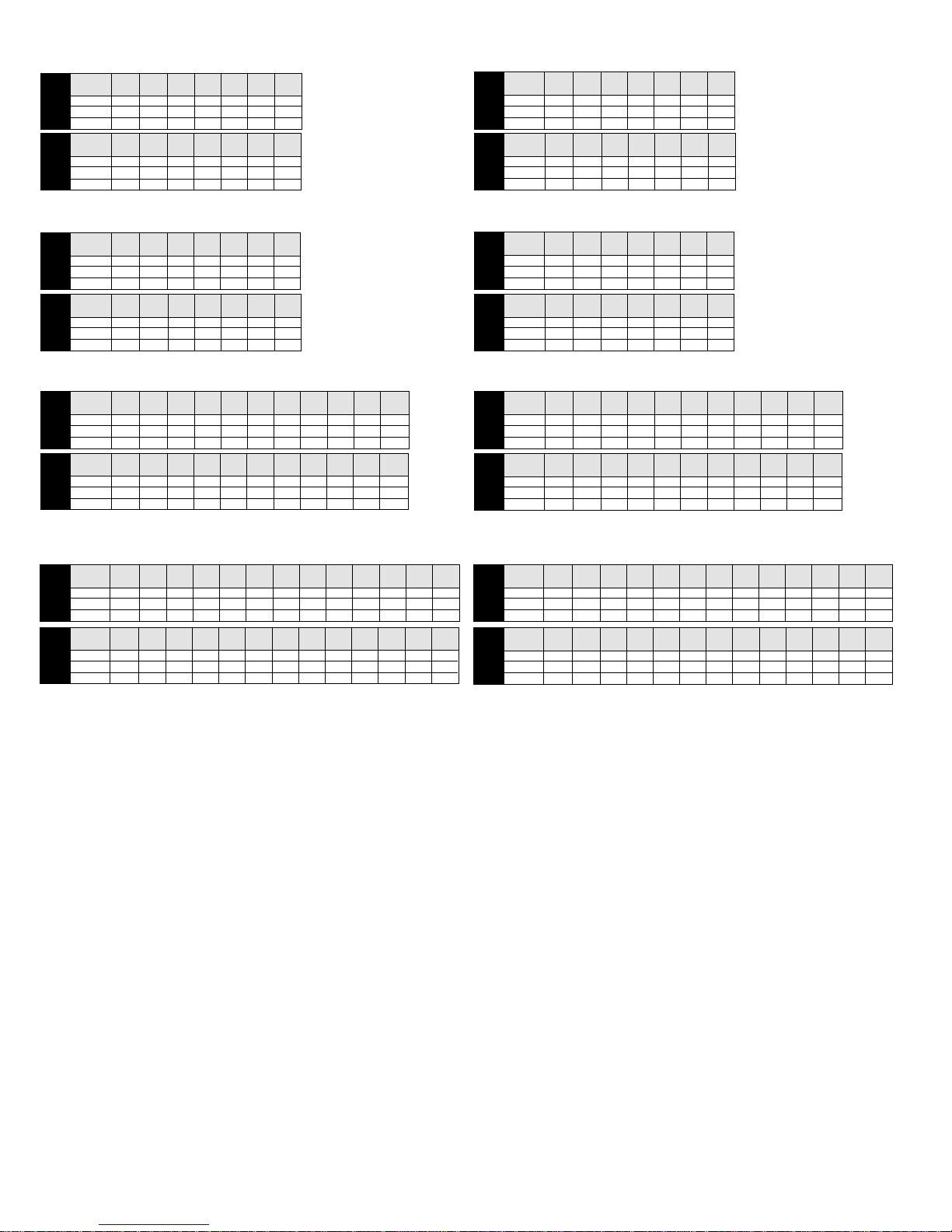
Models 9303C-HM3C-SP at 0' Lift, 5' Lift, 10' lift, & 15' Lift
Hydraulic GPM at GPM at GPM at GPM at GPM at GPM at GPM at
Flow 10 PSI 20 PSI 30 PSI 40 PSI 50 PSI 60 PSI 70 PSI
15 GPM
18 GPM
at 0´ Lift
20 GPM
9303C-HM3C-SP
Hydraulic GPM at GPM at GPM at GPM at GPM at GPM at GPM at
15 GPM
18 GPM
at 10´ Lift
20 GPM
9303C-HM3C-SP
92 77 53 26
100 98 88 71 49 28
100 99 98 90 74 52 31
Flow 10 PSI 20 PSI 30 PSI 40 PSI 50 PSI 60 PSI 70 PSI
75 68 53 26
76 75 72 63 49 28
75 74 73 72 68 52 31
Models 9303C-HM4C-SP at 0' Lift, 5' Lift, 10' lift, & 15' Lift
Hydraulic GPM at GPM at GPM at GPM at GPM at GPM at GPM at
Flow 10 PSI 20 PSI 30 PSI 40 PSI 50 PSI 60 PSI 70 PSI
5 GPM
78 58 36 11
6 GPM
at 0´ Lift
9303C-HM4C-SP
Hydraulic GPM at GPM at GPM at GPM at GPM at GPM at GPM at
at 10´ Lift
9303C-HM4C-SP
89 76 61 43 27 10
7 GPM
96 85 74 62 49 35 21
Flow 10 PSI 20 PSI 30 PSI 40 PSI 50 PSI 60 PSI 70 PSI
5 GPM
69 55 36 11
6 GPM
76 72 59 43 27 10
7 GPM
75 74 72 62 49 35 21
Models 9303C-HM5C-SP at 0' Lift, 5' Lift, 10' lift, & 15' Lift
Hydraulic GPM at GPM at GPM at GPM at GPM at GPM at GPM at GPM at GPM at GPM at GPM at
Flow 10 PSI 20 PSI 30 PSI 40 PSI 50 PSI 60 PSI 70 PSI 80 PSI 90 PSI 100 PSI110 PSI
13 GPM
101 100 99 95 80 59 40 21
14 GPM
at 0´ Lift
9303C-HM5C-SP
at 10´ Lift
9303C-HM5C-SP
101 100 99 98 94 82 61 43 27 10
15 GPM
101 100 99 98 97 95 87 66 50 33 16
Hydraulic GPM at GPM at GPM at GPM at GPM at GPM at GPM at GPM at GPM at GPM at GPM at
Flow 10 PSI 20 PSI 30 PSI 40 PSI 50 PSI 60 PSI 70 PSI 80 PSI 90 PSI 100 PSI110 PSI
13 GPM
14 GPM
15 GPM
75 74 73 72 69 59 40 21
76 74 73 72 71 69 61 43 27 10
76 75 74 73 72 71 70 66 50 33 16
Hydraulic GPM at GPM at GPM at GPM at GPM at GPM at GPM at
Flow 10 PSI 20 PSI 30 PSI 40 PSI 50 PSI 60 PSI 70 PSI
15 GPM
86 72 53 26
18 GPM
at 5´ Lift
9303C-HM3C-SP
at 15´ Lift
9303C-HM3C-SP
at 5´ Lift
9303C-HM4C-SP
at 15´ Lift
9303C-HM4C-SP
at 5´ Lift
9303C-HM5C-SP
at 15´ Lift
9303C-HM5C-SP
91 89 84 71 49 28
20 GPM
91 90 88 83 71 52 31
Hydraulic GPM at GPM at GPM at GPM at GPM at GPM at GPM at
Flow 10 PSI 20 PSI 30 PSI 40 PSI 50 PSI 60 PSI 70 PSI
15 GPM
18 GPM
20 GPM
Hydraulic GPM at GPM at GPM at GPM at GPM at GPM at GPM at
Hydraulic GPM at GPM at GPM at GPM at GPM at GPM at GPM at
Hydraulic GPM at GPM at GPM at GPM at GPM at GPM at GPM at GPM at GPM at GPM at GPM at
Flow 10 PSI 20 PSI 30 PSI 40 PSI 50 PSI 60 PSI 70 PSI 80 PSI 90 PSI 100 PSI110 PSI
13 GPM
14 GPM
15 GPM
Hydraulic GPM at GPM at GPM at GPM at GPM at GPM at GPM at GPM at GPM at GPM at GPM at
Flow 10 PSI 20 PSI 30 PSI 40 PSI 50 PSI 60 PSI 70 PSI 80 PSI 90 PSI 100 PSI110 PSI
13 GPM
14 GPM
15 GPM
66 64 53 26
65 64 63 60 49 28
66 65 64 62 59 52 31
Flow 10 PSI 20 PSI 30 PSI 40 PSI 50 PSI 60 PSI 70 PSI
5 GPM
75 58 36 11
6 GPM
86 74 61 43 27 10
7 GPM
88 83 73 62 49 35 21
Flow 10 PSI 20 PSI 30 PSI 40 PSI 50 PSI 60 PSI 70 PSI
5 GPM
62 51 36 11
6 GPM
65 64 59 43 27 10
7 GPM
66 65 64 60 49 35 21
90 89 88 85 76 59 40 21
90 89 88 87 85 78 61 43 27 10
90 89 88 87 86 84 79 66 50 33 16
66 65 64 63 61 54 40 21
67 65 64 63 62 60 54 43 27 10
67 65 64 63 62 61 60 58 50 33 16
Models 9305C-HM3C-SP at 0' Lift, 5' Lift, 10' lift, & 15' Lift
Hydraulic GPM at GPM at GPM at GPM at GPM at GPM at GPM at GPM at GPM at GPM at GPM at GPM at GPM at
Flow 10 PSI 20 PSI 30 PSI 40 PSI 50 PSI 60 PSI 70 PSI 80 PSI 90 PSI 100 PSI 110 PSI 120 PSI 130 PSI
17 GPM
152 150 148 146 135 119 99 81 58 37
18 GPM
at 0´ Lift
9305C-HM3C-SP
at 10´ Lift
9305C-HM3C-SP
153 152 150 149 147 137 120 102 82 61 40 16
19 GPM
156 155 153 152 150 148 137 117 102 82 63 43 22
Hydraulic GPM at GPM at GPM at GPM at GPM at GPM at GPM at GPM at GPM at GPM at GPM at GPM at GPM at
Flow 10 PSI 20 PSI 30 PSI 40 PSI 50 PSI 60 PSI 70 PSI 80 PSI 90 PSI 100 PSI110 PSI 120 PSI 130 PSI
17 GPM
135 135 134 133 130 119 99 81 58 37
18 GPM
133 132 131 131 130 129 120 102 82 61 40 16
19 GPM
127 126 125 124 123 122 121 117 102 82 63 43 22
Hydraulic GPM at GPM at GPM at GPM at GPM at GPM at GPM at GPM at GPM at GPM at GPM at GPM at GPM at
Flow 10 PSI 20 PSI 30 PSI 40 PSI 50 PSI 60 PSI 70 PSI 80 PSI 90 PSI 100 PSI 110 PSI 120 PSI130 PSI
17 GPM
145 143 140 138 134 119 99 81 58 37
18 GPM
at 5´ Lift
9305C-HM3C-SP
at 15´ Lift
9305C-HM3C-SP
147 146 144 142 140 132 120 102 82 61 40 16
19 GPM
147 146 145 143 142 140 134 117 102 82 63 43 22
Hydraulic GPM at GPM at GPM at GPM at GPM at GPM at GPM at GPM at GPM at GPM at GPM at GPM at GPM at
Flow 10 PSI 20 PSI 30 PSI 40 PSI 50 PSI 60 PSI 70 PSI 80 PSI 90 PSI 100 PSI 110 PSI120 PSI 130 PSI
17 GPM
120 119 119 119 118 113 99 81 58 37
18 GPM
108 107 107 106 105 104 100 95 82 61 40 16
19 GPM
107 107 106 106 105 104 102 100 95 82 63 43 22
-18-
Page 19
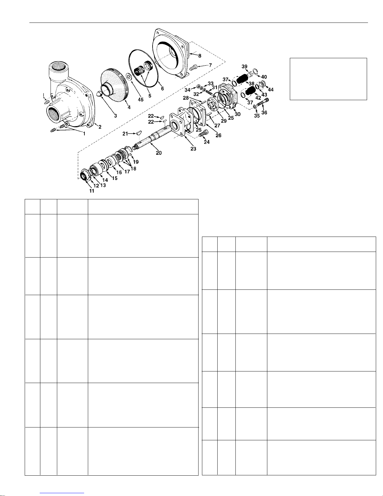
Models 9303C-HM1C, 9303C-HM2C, 9303C-HM3C, 9303C-HM4C and 9303C-HM5C
Ref. Qnty. Part
No. Req'd. No. Description
1 4 2406-0007 Drain/Vent Plug
2 1 0150-9000C Pump Casing (Volute) (Includes a
stainless steel wear ring)
3 1 2253-0002 Impeller Nut
4 1 0401-9100P Impeller (Nyglass, std.)
4 1 0402-9100P Impeller (Optional Polypropylene)
5 1 2120-0008 Mechanical Seal (Buna-N) 9301 Models
5 1 2120-0009 Mechanical Seal (Viton) 9303 Models
6 1 1720-0083 O-ring
7 4 2210-0020 Hex Head Cap Screw
8 1 0750-9300C Mounting Flange
11 1 1410-0056 Slinger Ring
12 1 1820-0013 Retaining Ring
13 1 1810-0014 Snap Ring
14 1 2000-0010 Ball Bearing
15 1 1410-0073 Spacer
16 1 2104-0005 Shaft Seal
17 1 1410-0074 Seal Spacer
18 1 2029-0014 Thrust Bearing Assembly—Consists of:
(1) Thrust Bearing & (2) Thrust Brg. Races
19 1 1810-0026 Snap Ring
20 1 0509-2500 Shaft (HM2C & HM4C Models) 6 3⁄4" Long
20 1 0511-2501 Shaft (HM1C & HM5C Models) 7" Long
20 1 0510-2500 Shaft (HM3C Models) 7 1⁄2" Long
21 1 1610-0012 Woodruff Key
22 1 1610-0032 Roll Pin (HM2C & HM4C Models)
22 1 1610-0031 Roll Pin (HM1C & HM5C Models)
22 1 1610-0030 Woodruff Key (HM3C Models)
23 1 0151-2500C Motor Body (Includes Main Bearing)
24 4 2210-0005 Hex Head Cap Screw
25 2 1720-0110 O-ring
26 1 0701-2500C Gerotor Housing (HM2C Models) 1⁄4" Wide
26 1 0700-2500C Gerotor Housing (HM1C Models) 1⁄2" Wide
26 1 0703-2500C Gerotor Housing (HM4C Models) 5⁄16" Wide
26 1 0702-2500C Gerotor Housing (HM3C Models) 1" Wide
26 1 0704-2500C Gerotor Housing (HM5C Models) 5⁄8" Wide
NOTE: When ordering parts, give
QUANTITY, PART NUMBER,
DESCRIPTION, and COMPLETE
MODEL NUMBER. Reference
numbers are used ONLY to identify
parts in the drawing and are NOT to
be used as order numbers.
Repair Parts Kit No. 3430-0332
Contains: One mechanical seal
(Ref. 5), one o-ring (Ref. 6) and
one rubber gasket (Ref. 45).
Parts Kit No. 3430-0178
Contains: One each ball bearing
(Ref. 14), motor shaft seal (Ref.
16), thread seal gasket (Ref. 32),
and washer (Ref. 33), two each
motor housing o-rings (Ref. 25),
and port adapter o-rings (Ref. 37).
Adapter Kit No. 3430-0187
(HM4 Models Only):
Hydraulic Motor Part #s
2500-0009C (HM1C Models)
2500-0010C (HM2C Models)
2500-0011C (HM3C Models)
2500-0012C (HM4C Models)
2500-0018C (HM5C Models)
Includes one each Ref. 37, Ref.
42, and Ref. 44, three Ref. 43,
three metering orifices one
No. 3373-0020 (Size #1), one
No. 3373-0021 (Size #2) and one
No. 3373-0022 (Size #3).
Ref. Qnty. Part
No. Req'd. No. Description
27 1 1600-0045 Dowel Pin (HM2C & HM4C Models)
27 1 1600-0044 Dowel Pin (HM1C & HM5CModels)
27 1 1600-0052 Dowel Pin (HM3C Models)
28 1 1600-0042 Dowel Pin (HM2C & HM4C Models)
28 1 1600-0037 Dowel Pin (HM1C & HM5C Models)
28 1 1600-0068 Dowel Pin (HM3C Models)
29 1 3900-0022 Gerotor (HM1C Models)
29 1 3900-0023 Gerotor (HM2C Models)
29 1 3900-0024 Gerotor (HM3C Models)
29 1 3900-0025 Gerotor (HM4C Models)
29 1 3900-0048 Gerotor (HM5C Models)
30 1 0251-2500C Motor End Plate (Includes Main Bearing)
31 1 3220-0029 Bypass Adjusting Screw
32 1 1700-0047 Gasket
33 1 2270-0027 Washer
34 1 2250-0038 Lock Nut
35 4 2270-0039 Washer
36 4 2220-0045 Cap Screw (HM2C & HM4C Models)
36 4 2220-0021 Cap Screw (HM1C & HM5C Models)
36 4 2220-0044 Cap Screw (HM3C Models)
37 2 1720-0108 O-ring
38 1 3320-0016 Tank Port Adapter
39 1 3260-0039 Poppet
40 1 1820-0023 Retaining Ring
42 1 3360-0021 Pressure Port Adapter
43 1 1720-0105 Orifice O-ring (HM2C & HM4C Models Only)
44 1 3373-0020 Metering Orifice
3373-0021 (HM2C & HM4C Models Only)
or 3373-0022
45 1 1700-0100 Rubber Gasket
-19-
Page 20
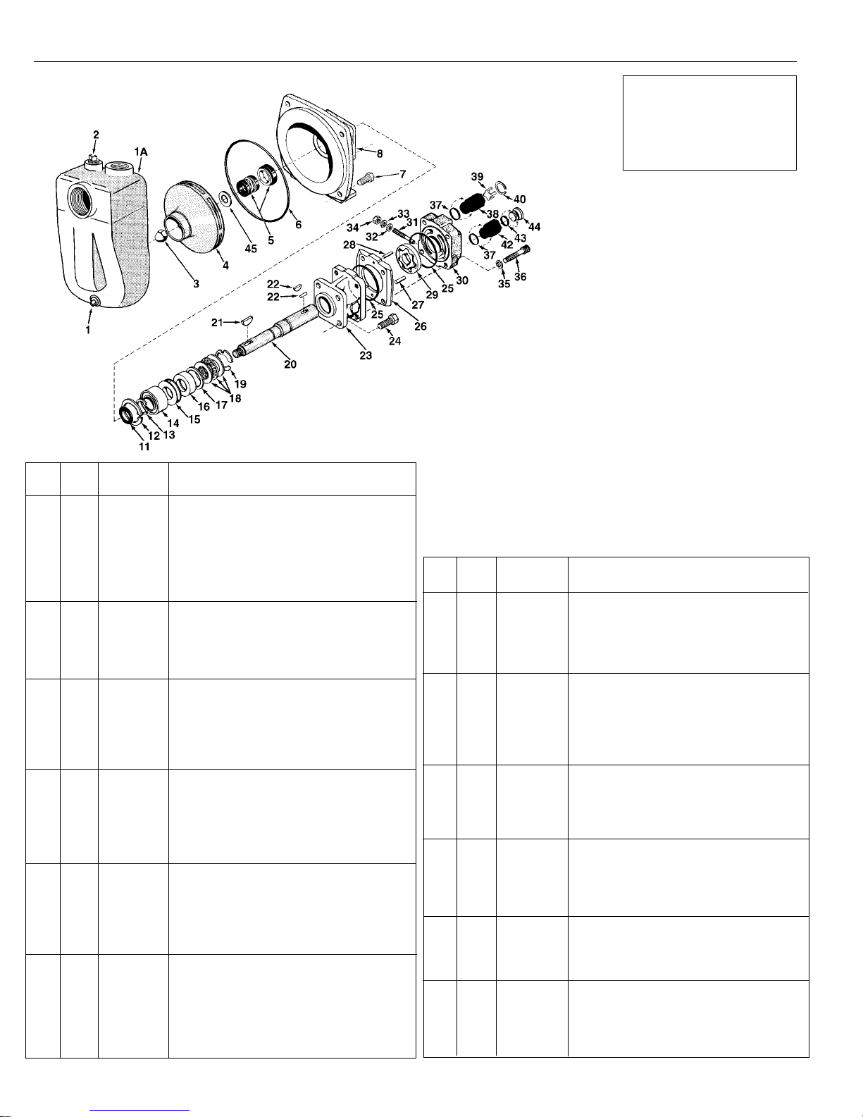
Models 9303C-HM1C-SP, 9303C-HM2C-SP, 9303C-HM3C-SP, 9303C-HM4C-SP and 9303C-HM5C-SP
Self-Priming, Hydraulically-Driven Centrifugals
Ref. Qnty. Part
No. Req'd. No. Description
1A 1 0150-9070C Pump Casing (Self Priming) (Includes a
stainless steel wear ring)
1 1 2406-0007 Drain/Vent Plug
2 1 2406-0001 Vent Plug
3 1 2253-0002 Impeller Nut
4 1 0401-9100P Impeller (Nyglass, std.)
4 1 0402-9100P Impeller (Optional Polypropylene)
5 1 2120-0008 Mechanical Seal (Buna-N) 9301 Models
5 1 2120-0009 Mechanical Seal (Viton) 9303 Models
6 1 1720-0083 O-ring
7 4 2210-0020 Hex Head Cap Screw
8 1 0750-9300C Mounting Flange
11 1 1410-0056 Slinger Ring
12 1 1820-0013 Retaining Ring
13 1 1810-0014 Snap Ring
14 1 2000-0010 Ball Bearing
15 1 1410-0073 Spacer
16 1 2104-0005 Shaft Seal
17 1 1410-0074 Seal Spacer
18 1 2029-0014 Thrust Bearing Assembly—Consists of:
(1) Thrust Bearing & (2) Thrust Brg. Races
19 1 1810-0026 Snap Ring
20 1 0509-2500 Shaft (HM2C & HM4C Models) 6 3⁄4" Long
20 1 0511-2501 Shaft (HM1C & HM5C Models) 7" Long
20 1 0510-2500 Shaft (HM3C Models) 7 1⁄2" Long
21 1 1610-0012 Woodruff Key
22 1 1610-0032 Roll Pin (HM2C & HM4C Models)
22 1 1610-0031 Roll Pin (HM1C & HM5C Models)
22 1 1610-0030 Woodruff Key (HM3C Models)
23 1 0151-2500C Motor Body (Includes Main Bearing)
24 4 2210-0005 Hex Head Cap Screw
25 2 1720-0110 O-ring
26 1 0701-2500C Gerotor Housing (HM2C Models) 1⁄4" Wide
26 1 0700-2500C Gerotor Housing (HM1C Models) 1⁄2" Wide
26 1 0703-2500C Gerotor Housing (HM4C Models) 5⁄16" Wide
26 1 0702-2500C Gerotor Housing (HM3C Models) 1" Wide
26 1 0704-2500C Gerotor Housing (HM5C Models) 5⁄8" Wide
NOTE: When ordering parts, give
QUANTITY, PART NUMBER,
DESCRIPTION, and COMPLETE
MODEL NUMBER. Reference
numbers are used ONLY to identify
parts in the drawing and are NOT to
be used as order numbers.
SP Chamber Kit No. 3430-0480SP
Contains: One chamber with wear
ring, (Ref. 1A), one o-ring (Ref. 6),
one drain/vent plug (Ref. 1) and one
vent plug (Ref. 2).
Repair Parts Kit No. 3430-0332
Contains: One mechanical seal
(Ref. 5), one o-ring (Ref. 6) and one
rubber gasket (Ref. 45).
Parts Kit No. 3430-0178
Contains: One each ball bearing
(Ref. 14), motor shaft seal (Ref.
16), thread seal gasket (Ref. 32),
and washer (Ref. 33), two each
motor housing o-rings (Ref. 25),
and port adapter o-rings (Ref. 37).
Adapter Kit No. 3430-0187
Hydraulic Motor Part #s
2500-0009C (HM1C Models)
2500-0010C (HM2C Models)
2500-0011C (HM3C Models)
2500-0012C (HM4C Models)
2500-0018C (HM5C Models)
(HM4 Models Only):
Includes one each Ref. 37, Ref.
42, and Ref. 44, three Ref. 43,
three metering orifices one
No. 3373-0020 (Size #1), one
No. 3373-0021 (Size #2) and one
No. 3373-0022 (Size #3).
Ref. Qnty. Part
No. Req'd. No. Description
27 1 1600-0045 Dowel Pin (HM2C & HM4C Models)
27 1 1600-0044 Dowel Pin (HM1C & HM5C Models)
27 1 1600-0052 Dowel Pin (HM3C Models)
28 1 1600-0042 Dowel Pin (HM2C & HM4C Models)
28 1 1600-0037 Dowel Pin (HM1C & HM5CModels)
28 1 1600-0068 Dowel Pin (HM3C Models)
29 1 3900-0023 Gerotor (HM2C Models)
29 1 3900-0022 Gerotor (HM1C Models)
29 1 3900-0024 Gerotor (HM3C Models)
29 1 3900-0025 Gerotor (HM4C Models)
29 1 3900-0048 Gerotor (HM5C Models)
30 1 0251-2500C Motor End Plate (Includes Main Bearing)
31 1 3220-0029 Bypass Adjusting Screw
32 1 1700-0047 Gasket
33 1 2270-0027 Washer
34 1 2250-0038 Lock Nut
35 4 2270-0039 Washer
36 4 2220-0045 Cap Screw (HM2C & HM4C Models)
36 4 2220-0021 Cap Screw (HM1C & HM5C Models)
36 4 2220-0044 Cap Screw (HM3C Models)
37 2 1720-0108 O-ring
38 1 3320-0016 Tank Port Adapter
39 1 3260-0039 Poppet
40 1 1820-0023 Retaining Ring
42 1 3360-0021 Pressure Port Adapter
43 1 1720-0105 Orifice O-ring (HM2C & HM4C Models Only)
44 1 3373-0020 Metering Orifice
45 1 1700-0100 Rubber Gasket
3373-0021 (HM2C & HM4C Models Only)
or 3373-0022
-20-
Page 21
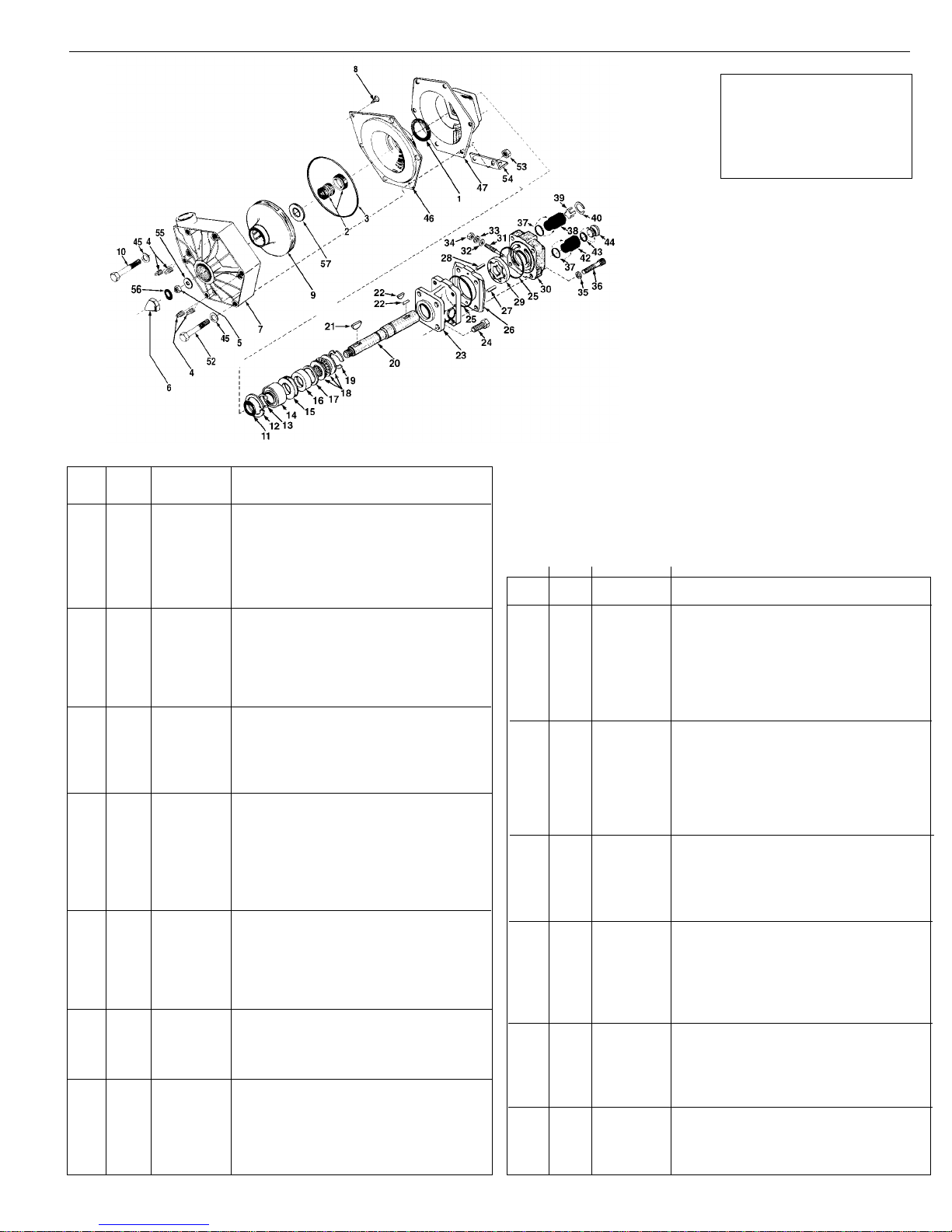
Models 9303P-HM1C, 9303P-HM3C, and 9303P-HM4C
Ref. Qnty. Part
No. Req'd. No. Description
1 1 1410-0082 Spacer
2 1 2120-0009 Mechanical Seal
3 1 1721-0083 O-Ring
4 4 2406-0020 Pipe Plug
5 1 2250-0051 Jam Nut
6 1 2250-0052 Impeller Nut
7 1 0700-9000P Pump Casing
8 1 2210-0088 Screw
9 1 0402-9100P Impeller
10 4 2210-0087 Hex Head Cap Screw
11 1 1410-0056 Slinger Ring
12 1 1820-0013 Retaining Ring
13 1 1810-0014 Snap Ring
14 1 2000-0010 Ball Bearing
15 1 1410-0073 Spacer
16 1 2104-0005 Shaft Seal
17 1 1410-0074 Seal Spacer
18 1 2029-0014 Thrust Bearing Assembly: Includes
(1) Thrust Bearing
(2) Thrust Bearing Races
19 1 1810-0026 Snap Ring
20 1 0507-2500 Shaft HM4C, 71⁄16˝ Long
20 1 0514-2500 Shaft HM3C, 713⁄16˝ Long
20 1 0506-2500 Shaft HM1C, 7 5⁄16˝ Long
21 1 1610-0012 Woodruff Key
22 1 1610-0032 Roll Pin (HM4C Model)
22 1 1610-0030 Woodruff Key (HM3C Model)
22 1 1610-0031 Roll Pin (HM1C Model)
23 1 0151-2500C Motor Body: Includes (1) Main Bearing
24 4 2210-0021 Hex Head Cap Screw
25 2 1720-0110 O-Ring
26 1 0700-2500C Gerotor Housing (HM1C Model) 1⁄2" Wide
26 1 0703-2500C Gerotor Housing (HM4C Model) 5⁄16" Wide
26 1 0702-2500C Gerotor Housing (HM3C Model) 1" Wide
27 1 1600-0045 Dowel Pin (HM4C Model)
27 1 1600-0052 Dowel Pin (HM3C Model)
27 1 1600-0044 Dowel Pin (HM1C Model)
28 1 1600-0042 Dowel Pin (HM4C Model)
28 1 1600-0068 Dowel Pin (HM3C Model)
NOTE: When ordering parts, give
QUANTITY, PART NUMBER,
DESCRIPTION, and COMPLETE
MODEL NUMBER. Reference
numbers are used ONLY to identify
parts in the drawing and are NOT to
be used as order numbers.
Repair Parts Kit No. 3430-0445
Contains: One mechanical seal
(Ref. 2), one o-ring (Ref. 3), one
washer (Ref. 55), one gasket
(Ref. 56) and one rubber gasket
(Ref. 57).
Parts Kit No. 3430-0178
Contains: One each ball bearing
(Ref. 14), motor shaft seal (Ref. 16),
thread seal gasket (Ref. 32), and
washer (Ref. 33), two each motor
housing o-rings (Ref. 25) and port
adapter o-rings (Ref. 37).
Hydraulic Motor Part #s
2500-0013C (HM3C Models)
2500-0014C (HM4C Models)
2500-0019C (HM1C Models)
Adapter Kit No. 3430-0187 (HM4 Models Only):
Includes one each Ref. 37, Ref. 42, and Ref. 44, three Ref. 43, three metering
orifices one No. 3373-0020 (Size #1), one No. 3373-0021 (Size #2) and one
No. 3373-0022 (Size #3).
Ref. Qnty. Part
No. Req'd. No. Description
28 1 1600-0037 Dowel Pin (HM1C Model)
29 1 3900-0025 Gerotor (HM4C Model)
29 1 3900-0024 Gerotor (HM3C Model)
29 1 3900-0022 Gerotor (HM1C Model)
30 1 0251-2500C Motor End Plate: Includes (1) Main Bearing
31 1 3220-0029 Valve Stem
32 1 1700-0047 Gasket
33 1 2270-0027 Washer
34 1 2250-0038 Lock Nut
35 4 2270-0039 Washer
36 4 2220-0045 Socket Head Cap Screw (HM4C Model)
36 4 2220-0044 Socket Head Cap Screw (HM3C Model)
36 4 2220-0021 Socket Head Cap Screw (HM1C Model)
37 2 1720-0108 O-ring
38 1 3320-0016 Check Valve Body
39 1 3260-0039 Poppet
40 1 1820-0023 Retaining Ring
42 1 3360-0021 Pressure Port Adapter
43 1 1720-0105 Orifice O-ring (HM4C Models Only)
44 1 3373-0020 Metering Orifice (HM4C Models Only)
3373-0021
3373-0022
45 6 2270-0041 Washer
46 1 0750-9300P Cover
47 1 0750-9006C Intermediate Flange
48 4 2250-0060 Hex Nut
50 4 2210-0021 Hex Head Cap Screw
52 2 2210-0016 Screw
53 2 2250-0008 Hex Nut
54 1 1510-0063 Mounting Foot
55 1 2270-0057 Washer
56 1 1700-0097 Gasket
57 1 1700-0100 Rubber Gasket
58 4 2250-0060 Nut (Not Shown)
-21-
Page 22
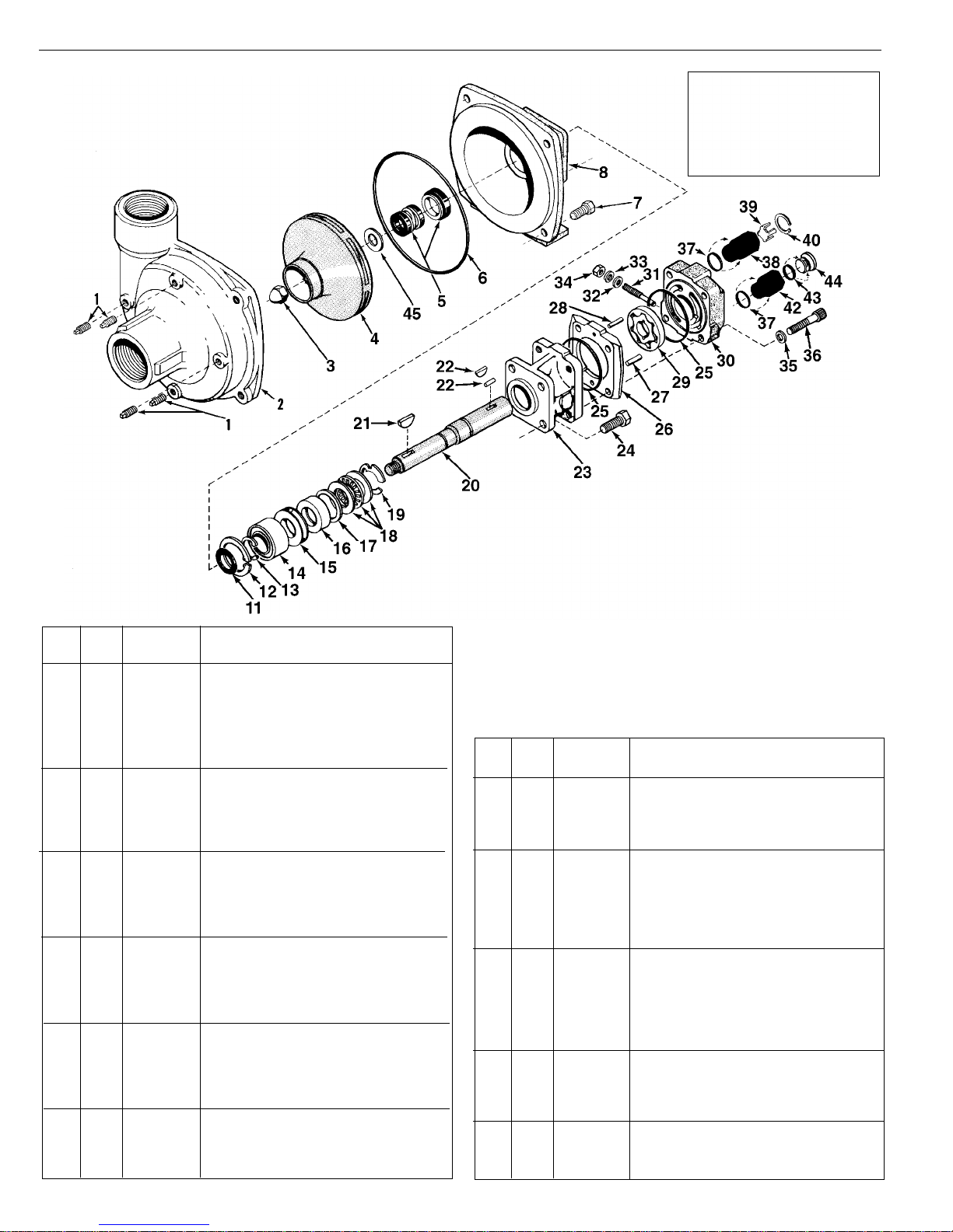
Models 9304C-HM1C, 9304C-HM3C, and 9304C-HM5C
NOTE: When ordering parts, give
QUANTITY, PART NUMBER,
DESCRIPTION, and COMPLETE
MODEL NUMBER. Reference
numbers are used ONLY to identify
parts in the drawing and are NOT to
be used as order numbers.
Ref. Qnty. Part
No. Req'd. No. Description
1 4 2406-0007 Drain/Vent Plug
2 1 0151-9200C Pump Casing (Volute) (Includes a
stainless steel wear ring)
3 1 2253-0002 Impeller Nut
4 1 0401-9200P Impeller
5 1 2120-0009 Mechanical Seal (Viton)
6 1 1720-0083 O-ring
7 4 2210-0020 Hex Head Cap Screw
8 1 0750-9300C Mounting Flange
11 1 1410-0056 Slinger Ring
12 1 1820-0013 Retaining Ring
13 1 1810-0014 Snap Ring
14 1 2000-0010 Ball Bearing
15 1 1410-0073 Spacer
16 1 2104-0005 Shaft Seal
17 1 1410-0074 Seal Spacer
18 1 2029-0014 Thrust Bearing Assembly—Consists of:
(1) Thrust Bearing & (2) Thrust Brg. Races
19 1 1810-0026 Snap Ring
20 1 0510-2500 Shaft (HM3C Model) 7 1⁄2˝ long
20 1 0511-2501 Shaft (HM1C & HM5C Models) 7˝ long
21 1 1610-0012 Woodruff Key
22 1 1610-0030 Woodruff Key (HM3C Models)
22 1 1610-0031 Roll Pin (HM1C and HM5C Models)
23 1 0151-2500C Motor Body (Includes Main Bearing)
24 4 2210-0005 Hex Head Cap Screw
25 2 1720-0110 O-ring
26 1 0700-2500C Gerotor Housing (HM1C Model) 1⁄2˝ wide
26 1 0702-2500C Gerotor Housing (HM3C Model) 1˝ wide
26 1 0704-2500C Gerotor Housing (HM5C Model) 5⁄8˝ wide
Repair Parts Kit No. 3430-0332
Contains: One mechanical seal
(Ref. 5), one o-ring (Ref. 6) and
one rubber gasket (Ref. 45).
Parts Kit No. 3430-0178
Contains: One each ball bearing
(Ref. 14), motor shaft seal (Ref.
Hydraulic Motor Part #s
2500-0011C (HM3C Models)
2500-0018C (HM5C Models)
2500-0009C (HM1C Models)
16), thread seal gasket (Ref. 32),
and washer (Ref. 33), two each
motor housing o-rings (Ref. 25),
and port adapter o-rings (Ref. 37).
Ref. Qnty. Part
No. Req'd. No. Description
27 1 1600-0052 Dowel Pin (HM3C Models)
27 1 1600-0044 Dowel Pin (HM1C and HM5C Models)
28 1 1600-0068 Dowel Pin (HM3C Model)
28 1 1600-0037 Dowel Pin (HM1C and HM5C Models)
29 1 3900-0022 Gerotor (HM1C Model)
29 1 3900-0024 Gerotor (HM3C Model)
29 1 3900-0048 Gerotor (HM5C Model)
30 1 0251-2500C Motor End Plate (Includes Main Bearing)
31 1 3220-0029 Bypass Adjusting Screw
32 1 1700-0047 Gasket
33 1 2270-0027 Washer
34 1 2250-0038 Lock Nut
35 4 2270-0039 Washer
36 4 2220-0044 Cap Screw (HM3C Models)
36 4 2220-0021 Cap Screw (HM1C)
36 4 2220-0032 Cap Screw (HM5C Models)
37 2 1720-0108 O-ring
38 1 3320-0016 Tank Port Adapter
39 1 3260-0039 Poppet
40 1 1820-0023 Retaining Ring
42 1 3360-0021 Pressure Port Adapter
45 1 1700-0100 Rubber Gasket
46 1 2270-0071 Washer (Not Shown)
-22-
Page 23
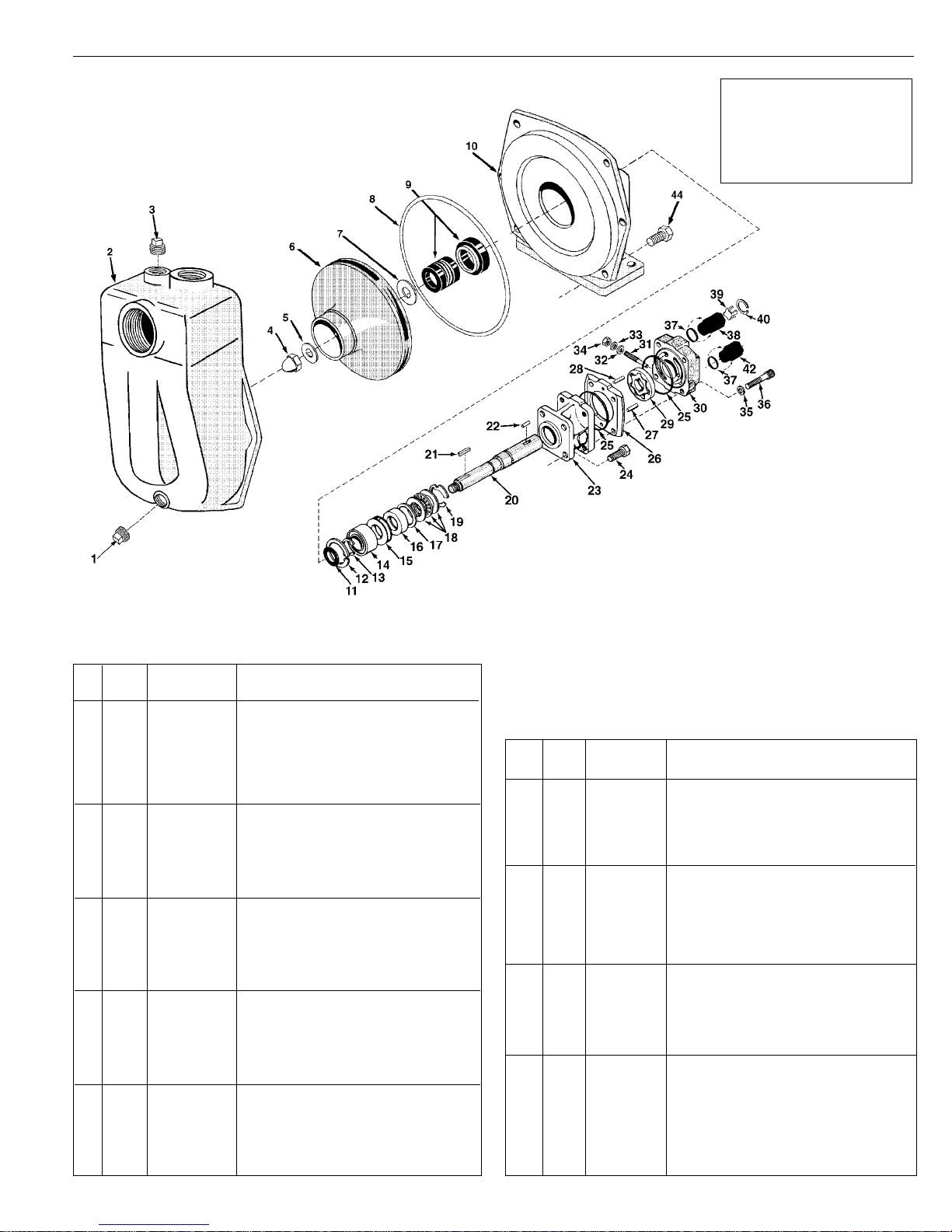
Models 9305C-HM3C-SP and 9305C-HM3C-BSP
NOTE: When ordering parts, give
QUANTITY, PART NUMBER,
DESCRIPTION, and COMPLETE
MODEL NUMBER. Reference
numbers are used ONLY to identify
parts in the drawing and are NOT to
be used as order numbers.
Ref. Qnty. Part
No. Req'd. No. Description
1 1 2406-0002 1/2" NPT Drain Plug (SP model only)
1 1 2406-0035 1/2" BSP Drain Plug (BSP model only)
2 1 0150-9075C Self-Priming Chamber (SP model only)—
(Includes a stainless steel wear ring)
2 1 0150-9075C1 Self-Priming Chamber (BSP model only)—
(Includes a stainless steel wear ring)
3 1 2406-0034 1" NPT Prime Port Plug (SP model only)
3 1 2406-0036 1" BSP Prime Port Plug (BSP model only)
4 1 2253-0002 Impeller Nut
5 1 2270-0071 Washer
6 1 0403-9200P1 Impeller
7 1 1700-0100 Rubber Gasket
8 1 1720-0180 O-ring
9 1 2120-0009 Mechanical Seal (standard Viton)
10 1 0752-9200C Mounting Flange
11 1 1410-0056 Slinger Ring
12 1 1820-0013 Retaining Ring
13 1 1810-0014 Snap Ring
14 1 2000-0010 Ball Bearing
15 1 1410-0073 Spacer
16 1 2104-0005 Shaft Seal
17 1 1410-0074 Seal Spacer
18 1 2029-0014 Thrust Bearing Assembly—Consists of:
(1) Thrust Bearing & (2) Thrust Brg. Races
19 1 1810-0026 Snap Ring
20 1 0514-2500 Shaft
Repair Parts Kit No. 3430-0500
Contains one each: mechanical seal
(Ref. 9), o-ring (Ref. 8), and rubber
gasket (Ref. 7).
Hydraulic Motor Part #s
2500-0013C
Parts Kit No. 3430-0178
Contains: One each: ball bearing
(Ref. 14), motor shaft seal (Ref.
16), thread seal gasket (Ref. 32),
and washer (Ref. 33); two each:
motor housing o-rings (Ref. 25),
and port adapter o-rings (Ref. 37).
Ref. Qnty. Part
No. Req'd. No. Description
21 1 1610-0053 Key
22 1 1610-0055 Key
23 1 0151-2500C Motor Body (Includes Main Bearing)
24 4 2210-0005 Hex Head Cap Screw
25 2 1720-0110 O-ring
26 1 0702-2500C Gerotor Housing 1" wide
27 1 1600-0052 Dowel Pin
28 1 1600-0068 Dowel Pin
29 1 3900-0024 Gerotor
30 1 0251-2500C Motor End Plate (Includes Main Bearing)
31 1 3220-0029 Bypass Adjusting Screw
32 1 1700-0047 Gasket
33 1 2270-0027 Washer
34 1 2250-0038 Lock Nut
35 4 2270-0039 Washer
36 4 2220-0044 Cap Screw
37 2 1720-0108 O-ring
38 1 3320-0016 Tank Port Adapter
39 1 3260-0039 Poppet
40 1 1820-0023 Retaining Ring
42 1 3360-0021 Pressure Port Adapter
44 6 2210-0086 Hex Head Cap Screw
-23-
Page 24
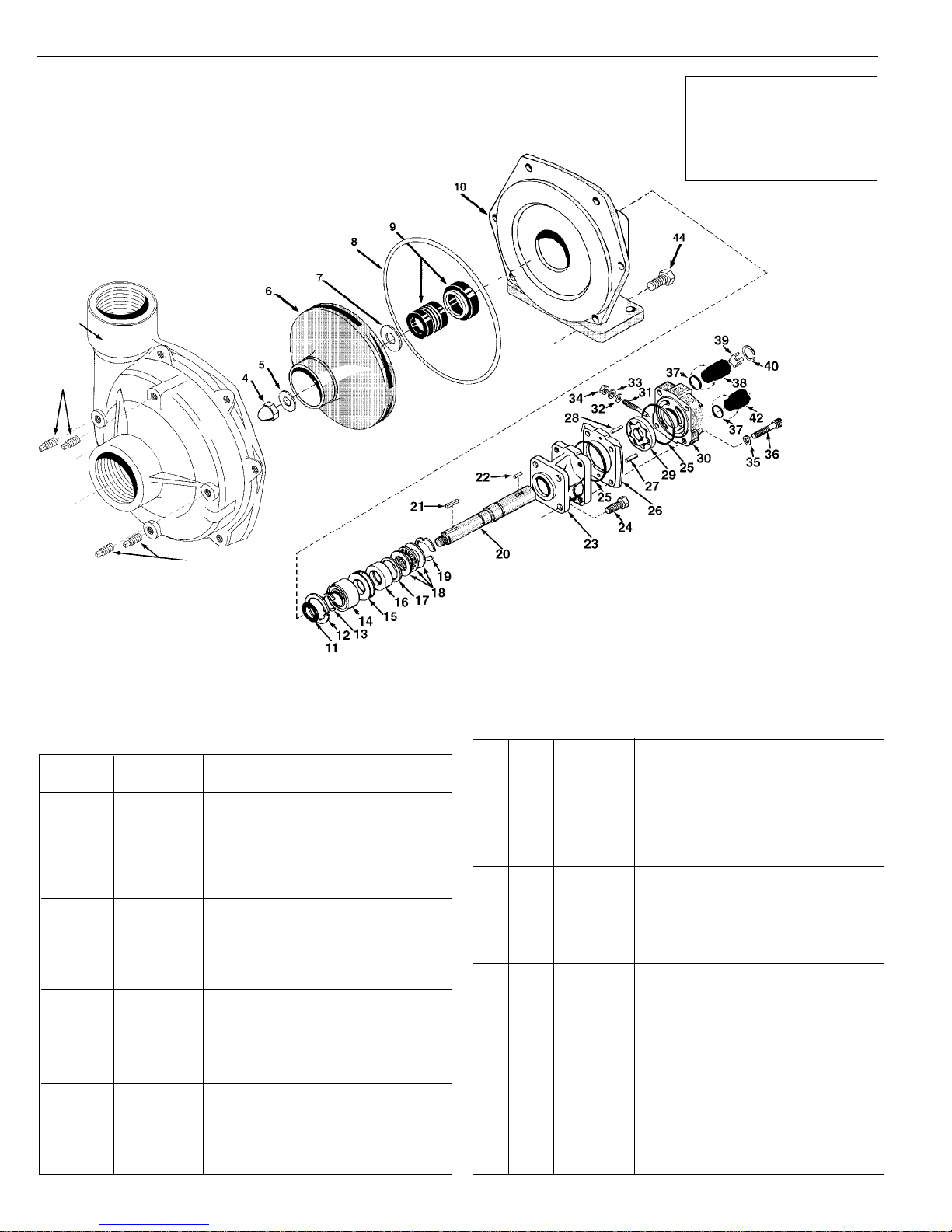
Models 9305C-HM3C
NOTE: When ordering parts, give
QUANTITY, PART NUMBER,
DESCRIPTION, and COMPLETE
MODEL NUMBER. Reference
numbers are used ONLY to identify
parts in the drawing and are NOT to
be used as order numbers.
2
1
1
Ref. Qnty. Part
No. Req'd. No. Description
1 4 2406-0007 Drain/Vent Plug
2 1 0152-9200CM Pump Casing (Includes a stainless steel
wear ring)
4 1 2253-0002 Impeller Nut
5 1 2270-0071 Washer
6 1 0403-9200P1 Impeller
7 1 1700-0100 Rubber Gasket
8 1 1720-0180 O-ring
9 1 2120-0009 Mechanical Seal (standard Viton)
10 1 0752-9200C Mounting Flange
11 1 1410-0056 Slinger Ring
12 1 1820-0013 Retaining Ring
13 1 1810-0014 Snap Ring
14 1 2000-0010 Ball Bearing
15 1 1410-0073 Spacer
16 1 2104-0005 Shaft Seal
17 1 1410-0074 Seal Spacer
18 1 2029-0014 Thrust Bearing Assembly—Consists of:
(1) Thrust Bearing & (2) Thrust Brg. Races
19 1 1810-0026 Snap Ring
20 1 0514-2500 Shaft
Repair Parts Kit No. 3430-0500
Contains one each: mechanical seal
(Ref. 9), o-ring (Ref. 8), and rubber
gasket (Ref. 7).
Hydraulic Motor Part #s
2500-0013C
Parts Kit No. 3430-0178
Contains: One each: ball bearing
(Ref. 14), motor shaft seal (Ref.
16), thread seal gasket (Ref. 32),
and washer (Ref. 33); two each:
motor housing o-rings (Ref. 25),
and port adapter o-rings (Ref. 37).
Ref. Qnty. Part
No. Req'd. No. Description
21 1 1610-0053 Key
22 1 1610-0055 Key
23 1 0151-2500C Motor Body (Includes Main Bearing)
24 4 2210-0005 Hex Head Cap Screw
25 2 1720-0110 O-ring
26 1 0702-2500C Gerotor Housing 1" wide
27 1 1600-0052 Dowel Pin
28 1 1600-0068 Dowel Pin
29 1 3900-0024 Gerotor
30 1 0251-2500C Motor End Plate (Includes Main Bearing)
31 1 3220-0029 Bypass Adjusting Screw
32 1 1700-0047 Gasket
33 1 2270-0027 Washer
34 1 2250-0038 Lock Nut
35 4 2270-0039 Washer
36 4 2220-0044 Cap Screw
37 2 1720-0108 O-ring
38 1 3320-0016 Tank Port Adapter
39 1 3260-0039 Poppet
40 1 1820-0023 Retaining Ring
42 1 3360-0021 Pressure Port Adapter
44 6 2210-0086 Hex Head Cap Screw
-24-
Page 25

Notes
-25-
Page 26

Notes
-26-
Page 27

Notes
-27-
Page 28
Limited Warranty on Hypro Pumps and Other Hypro Products
Hypro Corporation (“Hypro”) warrants to the original purchaser of its products (the “Purchaser”) that such products will be
free from defects in material and workmanship under normal use for the period of one (1) year for all products except: oil
crankcase plunger pumps will be free from defects in material and workmanship under normal use for the period of five (5)
years, and accessories will be free from defects in material and workmanship under normal use for the period of ninety
(90) days. In addition, Hypro warrants to the purchaser all forged brass pump manifolds will be free from defects in
material and workmanship under normal use and from damage resulting from environmental conditions for the life of the pump.
“Normal use” does not include use in excess of recommended maximum speeds, pressures, vacuums and temperatures,
or use requiring handling of fluids not compatible with component materials, as noted in Hypro product catalogs, technical
literature, and instructions. This warranty does not cover freight damage, freezing damage, normal wear and tear, or
damage caused by misapplication, fault, negligence, alterations, or repair that affects the performance or reliability of the
product.
THIS WARRANTY IS EXCLUSIVE. HYPRO MAKES NO OTHER WARRANTY, EXPRESS OR IMPLIED, INCLUDING
BUT NOT LIMITED TO ANY WARRANTY OF MERCHANTABILITY OR FITNESS FOR A PARTICULAR PURPOSE.
Hypro’s obligation under this warranty is, at Hypro’s option, to either repair or replace the product upon return of the entire
product to the Hypro factory in accordance with the return procedures set forth below. THIS IS THE EXCLUSIVE REM-
EDY FOR ANY BREACH OF WARRANTY.
IN NO EVENT SHALL HYPRO BE LIABLE FOR ANY INCIDENTAL OR CONSEQUENTIAL DAMAGES OF ANY KIND,
WHETHER FOR BREACH OF ANY WARRANTY, FOR NEGLIGENCE, ON THE BASIS OF STRICT LIABILITY, OR
OTHERWISE.
Return Procedures
All pumps or products
ous chemicals
must
must
be flushed of
any
chemical (ref. OSHA Section 0910.1200 (d)(e)(f)(g)(h)) and hazard-
be labeled before being shipped* to Hypro for service or warranty consideration. Hypro
reserves the right to request a Material Safety Data sheet from the Purchaser for any pump or product Hypro deems
necessary. Hypro reserves the right to “disposition as scrap” pumps or products returned which contain unknown substances, or to charge for any and all costs incurred for chemical testing and proper disposal of components containing
unknown substances. Hypro requests this in order to protect the environment and personnel from the hazards of handling
unknown substances.
For technical or application assistance, call the Hypro Technical/Application number: 1-800-445-8360.
To obtain service or warranty assistance, call the Hypro Service and Warranty number: 1-800-468-3428;
or call the Hypro Service and Warranty FAX: (651) 766-6618.
Be prepared to give Hypro full details of the problem, including the following information:
1. Model number and the date and from whom you purchased your pump.
2. A brief description of the pump problem, including the following:
• Liquid pumped. State the pH and any non-soluble • Drive type (gas engine/electric motor; direct/belt drive;
materials, and give the generic or trade name. tractor PTO) and rpm of pump.
• Temperature of the liquid and ambient environment. • Viscosity (of oil, or other than water weight liquid).
• Suction lift or vacuum (measured at the pump). • Elevation from the pump to the discharge point.
• Discharge pressure. • Size and material of inlet and outlet line.
• Size, type, and mesh of the inlet strainer. • Type of spray gun, orifice size, unloader/relief valve.
Hypro may request additional information, and may require a sketch to illustrate the problem.
Contact the factory to receive a return material authorization before sending the product. All pumps returned for warranty
work should be sent shipping charges prepaid to:
HYPRO CORPORATION
Attention: Service Department
375 Fifth Avenue NW
New Brighton, Minnesota 55112-3288
*Carriers, including U.S.P.S., airlines, UPS, ground freight, etc., require specific identification of any hazardous materials being shipped.
Failure to do so may result in a substantial fine and/or prison term. Check with your shipping company for specific instructions.
.
Conformance to 89/392/EEC (machine directive), as well as,
73/23/EEC (low voltage) and 89/336/ECC (electromagnetic
Printed in the USA
2000 Hypro Corporation
compatibility) as declared in standard EN809.
 Loading...