

Page 1
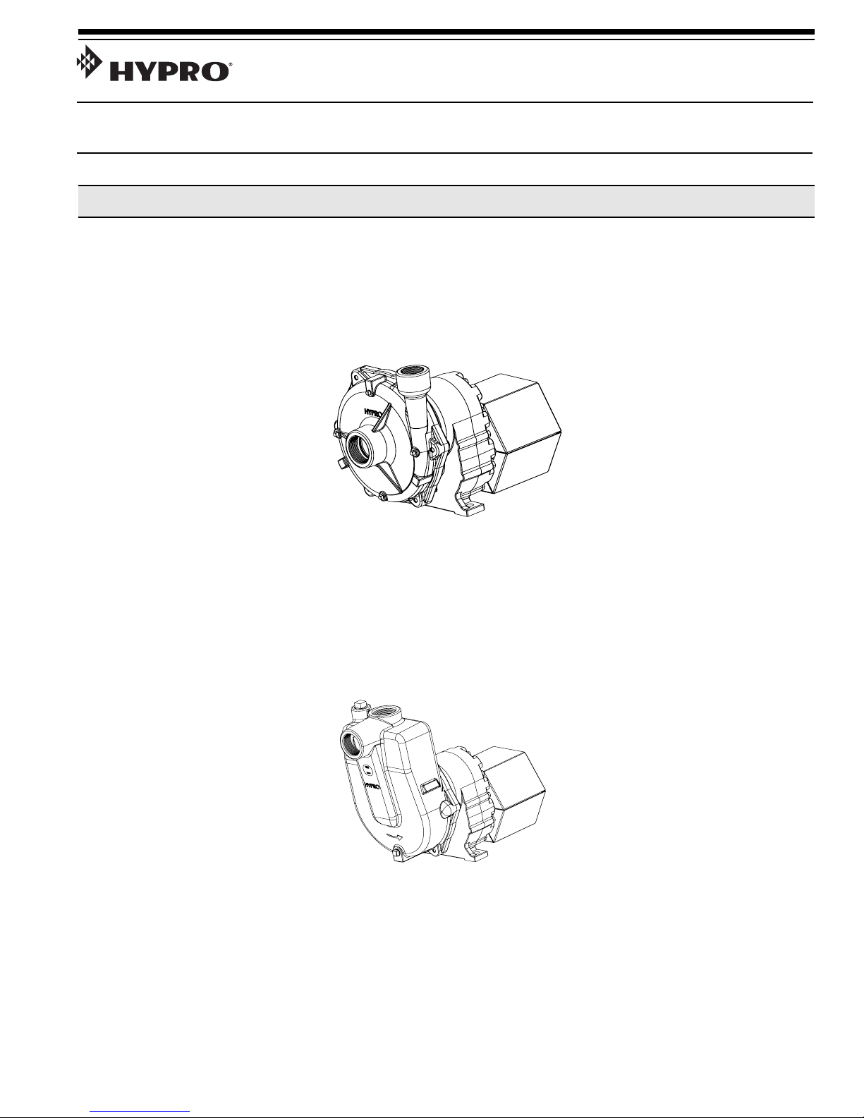
Series 9047
Gear-Driven Centrifugal Pumps
Installation, Operation, Repair and Parts Manual
Description
Form L-1529
12/11, Rev. C
Hypro Centrifugal Pumps handle big, high-capacity farm
spraying jobs with ease. Use them for spraying liquid fertilizers and other chemicals, including wettable powder
slurries for weed control. Make short work of other farm
jobs - filling nurse tanks, watering seed beds, and transferring liquids.
SERIES 9047C
Cast Iron, Gear-Driven
Centrifugal Pump
Max. Flow Rate: ..........213 gpm
Max. Pressure: ..............180 psi
Max. Speed:..................540 rpm
Ports: ....................2”" NPT inlet
Hypro gear-driven centrifugal pumps are sturdy, smooth
running units and are available in both standard and selfpriming models.
1-1/2" NPT outlet
SERIES 9047C-SP
and 9047C-BSP
Cast Iron, Gear-Driven,
Centrifugal Pump
Max. Flow Rate: ..........195 gpm
Max. Pressure: ..............170 psi
Max. Speed:..................540 rpm
Ports: ............ 2" NPT inlet (SP)
2" NPT
outlet (SP)
2” BSP inlet (BSP)
2” BSP outlet (BSP)
Page 2
General Safety Information
Notes are used to notify of installation, operation, or
maintenance information that is important but not
safety related.
Caution is used to indicate the presence of a hazard,
which will or may cause minor injury or property
damage if the notice is ignored.
Do not pump flammable or explosive fluids such as
gasoline, fuel oil, kerosene, etc. Do not use in explosive atmospheres. Components not rated for use
with Anhydrous Ammonia. The pump should only be
used with liquids compatible with the pump materials. Failure to follow this notice may result in severe
personal injury and/or property damage and will void
the product warranty.
Be sure all exposed moving parts, such as PTO
shafts and adapters, are properly shielded or guarded and that all coupling devices are securely
attached before applying power.
Warning denotes that a potential hazard exists and
indicates procedures that must be followed exactly
to either eliminate or reduce the hazard, and to avoid
serious personal injury, or prevent future safety
problems with the product.
Danger is used to indicate the presence of a hazard
that will result in severe personal injury, death, or
property damage if the notice is ignored.
• Provide adequate protection in guarding around
the moving parts such as shafts and pulleys.
Pumps mounted directly onto PTO shaft or other
power shaft must be prevented from rotating with
the power shaft. Pump must float freely on the
power shaft and must not be tied rigidly to equipment on which it is mounted.
Before servicing, disconnect all power. Make sure all
pressure in the system is relieved. Drain all liquids
from the system and flush.
• Drain all liquids from the system before servicing.
The sound pressure level of the pump may exceed
80dBA. Observe all safety precautions when operating the pump within close proximity for extended
periods by wearing hearing protectors. Extended
exposure to elevated sound levels will result in permanent loss of hearing acuteness, tinnitus, tiredness,
stress, and other effects such as loss of balance and
awareness.
• Do not pump at pressures higher than the
maximum recommended pressure.
• Operate the pump between a temperature range
• Make certain that the power source conforms to
o
of 45
freezing conditions by draining liquid and pumping rust-inhibiting antifreeze solution through the
system, coating the pump interior.
the requirements of your equipment.
to 140oF [7oto 60oC]. Protect pump from
Hazardous Substance Alert
• Secure the discharge line before starting the
pump. An unsecured discharge line may whip,
resulting in personal injury and/or property damage.
• Check all hoses for weak or worn condition before
each use. Make certain that all connections are
tight and secure.
• Periodically inspect the pump and the system
components. Perform routine maintenance as
required (See Maintenance).
• Use only pipe, hose, and hose fittings rated for
maximum rated pressure of the pump or the pressure at which the pressure relief valve is set at.
Do not use used pipe.
• Do not use these pumps for pumping water or
other liquids for human or animal consumption.
1. Always drain and flush pump before servicing or disassembling for any reason (see instructions).
2. Always drain and flush pump prior to returning unit
for repair.
3. Never store pumps containing hazardous chemicals.
L-1529 (12/11, Rev. C)
4. Before returning pump for service/repair, drain out all
liquids and flush unit with neutralizing liquid. Then,
drain the pump. Attach tag or include written notice
certifying that this has been done.
It is illegal to ship or transport any hazardous chemicals without United States Environmental Protection
Agency Licensing.
2
Page 3
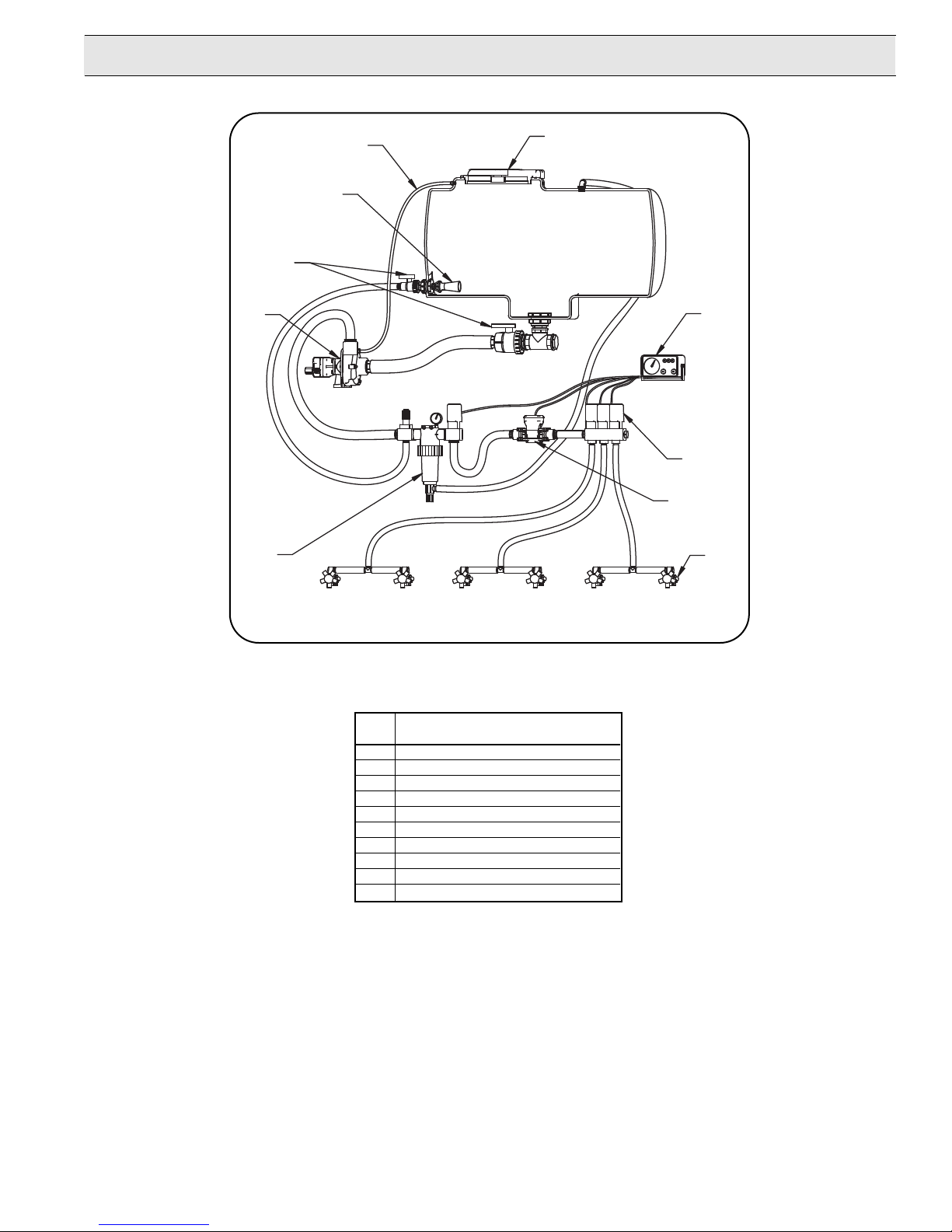
Plumbing Installation
2
3
4
5
7
1
6
8
9
10
Centrifugal Plumbing Hook-up
REF. DESCRIPTION
NO.
1 Tank Lid
2 Vent Line #3430-0456
3 Jet Agitator
4 Shut-off Ball Valves
5 Centrifugal Pump
6 Spray Control Console
7 Centrifugal Pump Control
8 Manifold Boom Valve
9 Electromagnetic Flowmeter
10 Compact Jet Turret Nozzle Body
3
L-1529 (12/11, Rev. C)
Page 4

Installation Instructions
Pump Installation:
The following are recommendations to achieve the optimal performance out of your centrifugal pump and your
spraying system.
Pump Inlet Line
To achieve full capacity from the pump, the inlet line
should be at least the same size as the inlet port on the
pump. Reducing this line size will restrict the capabilities
of the pump.
Check all fittings and connections in the suction line for
tightness. The introduction of air may affect the priming
and pumping capabilities of the pump. Use good quality
suction hose that will not be collapsed by suction.
For non-self-priming models, the centrifugal pump
should be mounted below the liquid level and as near to
the liquid source as possible to allow for the shortest
suction line practical. To achieve optimal performance,
the suction line should slope down into the pump. Avoid
rises and humps that could trap air in the line to the
pump. The suction line and pump should be filled with
liquid prior to starting the pump, and all discharge lines
should be open.
Pump Outlet Line
The recommended orientation for the outlet port is pointing straight up. This allows liquid to stay in the pump
while it is priming. The outlet line should be the same
size as the pressure port on the pump to give the opti
mal flow. The line should have as few restrictions and
elbows as possible to optimize the pump performance
and reduce pressure drop from the pump to the spray
tips.
Priming The Pump:
IMPORTANT: The pump must not be run dry.
Before starting the pump, the inlet line and pump must
be filled with liquid and all discharge lines must be open.
On self-priming models, only the pump chamber needs
to be filled with liquid. The pump must not be run unless
it is completely filled with liquid because there is a danger of damaging the mechanical seal, which depends on
the liquid for its lubrication.
Non-self-priming models should be mounted below the
level of the liquid. The suction line should slope down to
the pump and be free of dips and bends. If this cannot
be done, a foot valve should be installed in the end of
the inlet line so that the line can be completely filled with
liquid before starting the pump.
Centrifugal Pump Control
Hypro now offers many different components for spraying systems. The Hypro centrifugal pump control incorporates the electric flow control valve, a self-cleaning
line strainer
tation control valve.
The line must also be free of air leaks.
-
, a visual pressure gauge and a manual agi-
Flow Control V
A high-flow electric proportional valve allows for maximum flow control to the boom valves. It provides
smooth, rapid control that can be controlled from either
an electronic rate controller or switch box.
Strainers
The recommended placement of the strainer for a centrifugal pump is in the pump outlet line. This will eliminate any possible restriction that the strainer could create if it were installed in the inlet line. Ensure that the
proper strainer size and screen mesh are used to limit
the pressure drop and achieve the best filtration. Line
strainers can also be installed in the tank fill line to filter
liquid as it is loaded into the tank as well as in the boom
lines to further filter the solution prior to the spray tips.
Tank baskets can also be used to filter material added
through the tank lid.
Agitation
The centrifugal pump control contains a manual agitation
control valve that can be adjusted to provide the right
amount of flow to the jet agitators in the tank to ensure
proper mixing within the tank.
Flowmeter
To eliminate the mechanical problems of a turbine
flowmeter, we recommend that an electromagnetic
flowmeter be used. These flowmeters have no moving
parts to wear out and will provide a more consistent
and accurate flow reading. They can be input into just
about any electronic rate controller or switch box.
Boom Section Valves
For rapid response and reliability, we recommend electric plunger valves be used for boom control. The valves
should be sized accordingly to minimize the pressure
drop and maximize the flow rate. The boom tubing or
hose should be sized accordingly to ensure that a pressure drop in the lines does not occur, causing inconsistent pressures at the nozzles.
Nozzle Bodies
Nozzle bodies with shut-off check valves are recommended to eliminate dripping from the spray tips when
the boom valves are shut down.
alve
For further information
regarding Hypro products,
contact your local dealer
or Hypro directly at
www.hypropumps.com or by
calling 1-800-424-9776.
L-1529 (12/11, Rev. C)
4
Page 5

Operation and Maintenance
Engage the PTO clutch slowly and smoothly. Avoid
sudden starts and fast clutching that may damage
the drive section of the pump.
Controlling the Flow
Two Flow Control Valves are used - one in the agitation
line and one in the line leading to the boom or spray gun.
This permits controlling agitation flow independently of
nozzle flow.
To Adjust For Spraying
To adjust the sprayer (regardless of power source - PTO,
belt or pulley), follow these steps:
1.
Prime the pump with all valves open.
2. Close Control Valve and Agitation Line Valve; then
open the Boom Shut–Off Valve.
3. With the pump running, open the Control Valve until
the Pressure Gauge indicates desired spraying pressure.
4. Open the the Agitation Line Valve until sufficient agitation is observed. Then, if spraying pressure drops,
readjust the Control Valve to restore desired pressure.
5. Make sure flow is uniform from all nozzles.
After spraying adjustments are made, it is only necessary
to close the Boom Shut-Off Valve to discontinue spraying.
On belt-drive models, check belt tension daily or before
each use.
Flush Pump After Use
One of the most common causes for faulty pump performance is “gumming” or corrosion inside the pump. Flush the
pump and entire system with a solution that will chemically
neutralize the liquid pumped. Mix according to manufactur
er’s directions. This will dissolve most residue remaining in
the pump, leaving the inside of the pump clean for the next
use.
To Prevent Corrosion
After cleaning the pump as directed above, flush it with a
permanent-type automobile antifreeze (Prestone, Zerex,
etc.) containing a rust inhibitor
antifreeze and water. Plug the ports to keep out air during
storage. For short periods of idleness, non-corrosive liquids may be left in the pump, but air must be kept out. Plug
the ports or seal port connections.
. Use a 50/50 solution of
-
5
L-1529 (12/11, Rev. C)
Page 6
Repair Instructions
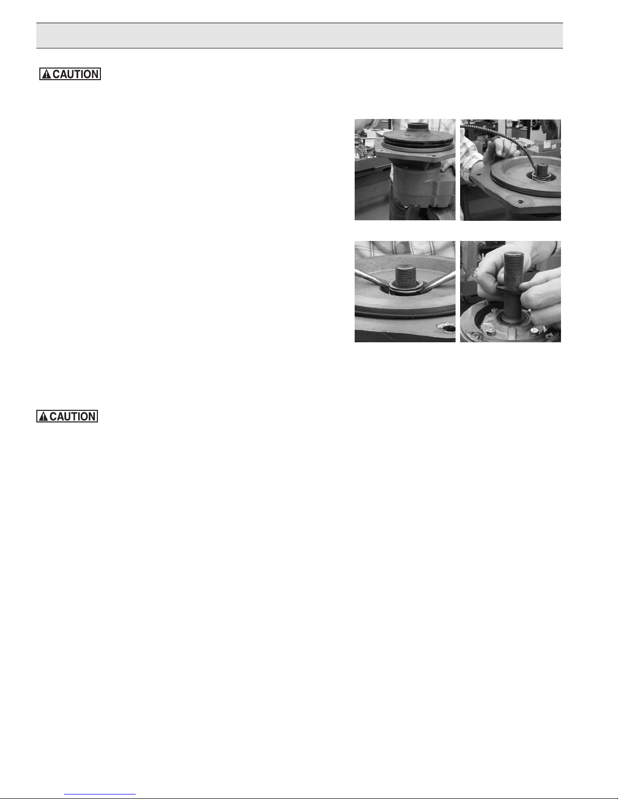
Always flush the pump with water or neutralizing agent before servicing.
Pump Housing Dissassembly
Remove the six casting cap screws with a 5/8” box wrench.
1.
Tap pump casing on discharge port with rubber hammer, if needed.
Check inside of pump casing, including suction port. If badly
eroded (or damaged), pump casting should be replaced.
2. To remove impeller, clamp the gear box shaft in vise as shown.
Take caution to protect shaft from being damaged by vise jaws.
This will prevent rotation of shaft and allow the impeller to be
unscrewed. To unscrew impeller, use a small diameter shaft or
file inserted into vanes and turn counterclockwise
Pump Seal Removal
3 Apply lubricant (WD-40 oil or detergent) to shaft and rubber boot
area of rotary seal for easier removal. Push seal down to allow
lubricant to penetrate around shaft.
4.
To remove rotary part of seal, use two screwdrivers positioned on
each side and pry up the rotary part of the seal.
Ref. 2
Ref. 3
5. Remove the four pump plate cap screws with 1/2” box
wrench. Then remove rubber slinger and stationary seat of seal
plus its o-ring seal from pump plate. It may be necessary to
destroy the stationary seal seat with a punch or chisel for removal.
Silicon carbide material is very brittle and will crack easily.
The seal will be damaged from removal. A new seal MUST be used when pump
is reassembled.
Ref. 4
Ref. 5
L-1529 (12/11, Rev. C)
6
Page 7
Repair - continued
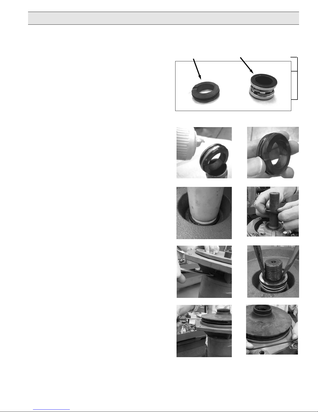
Be extremely careful with the new seal. Silicon carbide material is very hard, but also very brittle. If the seal is accidentally dropped and
hits a hard surface, the seal’s primary ring (rotary part) and mating ring (stationary seal seat) can be damaged. Also take precautions
not to introduce dirt or grit to the seal surfaces.
1. Inspect seal seat cavity to be sure it is clean and
without debris. Foreign material at the bottom of
the seal seat bore can cause the mating ring to be
slightly cocked.
Important:
Make sure seal cavity is clean and lubricated with
detergent; don’t use oil for assembly lubrication.
Mating Ring
(Stationary Part)
Primary Ring
(Rotary Part)
Head Assy.
2. Lubricate (Stationary Part) of seal and seal seat
cavity in mounting flange with detergent to aid in
smooth installation.
3. Install (Stationary Part) of seal into seat bore.
Note: The side of the mating ring with the notch
is positioned towards the bottom of the seal bore.
4. Press (Stationary Part) of seal into seal cavity bore
on pump mounting plate using a nylon or soft tool
applying uniform hand force. Seal will pop into place
and bottom out once o-ring has slipped inside the
leading edge of the seat cavity. Be sure seal is
completely seated and not cocked.
5. Install new rubber slinger onto gear box shaft over
(Rotary Part) of seal.
6. Next reassemble pump mounting plate with four
cap screws (torque to 15 ft-lbs) using 1/2 wrench
onto gear box. Index plate position to align weep
hole on plate to down position.
7. To install (Rotary Part) of seal, first lubricate shaft
and inside rubber boot of seal with one to two drops
of detergent in one cup of water only. (Note: Do
not use 100% detergent or oil for lubricant on this
part). Next install (Rotary Part) of seal onto shaft,
making sure silicon carbide end is facing down.
Lightly press (Rotary Part) of seal down shaft over
threaded area until it bottoms out on (Stationary
Part) of seal.
Life Guard Mechanical Seal
Ref. 2
Ref. 4
Ref. 1
Ref. 3
Ref. 5
Important:
Do not rotate or thread (Rotary Part) of seal down
on shaft over threaded area. This may cause cuts or
damage to inside of (Rotary Part) rubber boot.
8. Install rubber gasket (P/N 1700-0121) onto shaft
before re-installing impeller
.
9. Install impeller into shaft by hand threading
clockwise onto shaft. If you use a small diameter
shaft or file to do final tightening, do so lightly,
as too much force may damage impeller vanes.
10. Install o-ring on pump mounting plate. Replace
o-ring if worn or damaged.
11. Reassemble pump casting with six cap screws
(torque to 25 ft-lbs) using a 5/8” box wrench, and
tighten bolts evenly to compress o-ring seal.
Ref. 6
Ref. 9
7
Ref. 7
Ref. 10
L-1529 (12/11, Rev. C)
Page 8
Troubleshooting
Symptom Probable Cause(s) Corrective Action(s)
Low Discharge Pump not primed. - Remove topmost vent plug from face of pump and
run pump to expel trapped air (See Installation Instructions).
Air leaks in suction line. - Check and reseal inlet fittings.
Blocked or clogged line strainer. - Inspect strainer and clear any debris from screen.
Impeller plugged. - Inspect and clear obstruction.
Undersize suction line or collapsed hose. - Suction line should be the same diameter as inlet port of pump or
larger.
Eye of impeller rubbing on volute. - Remove volute (front cover) and inspect the impeller. If wear
detected, sand the impeller eye O.D. with emery cloth.
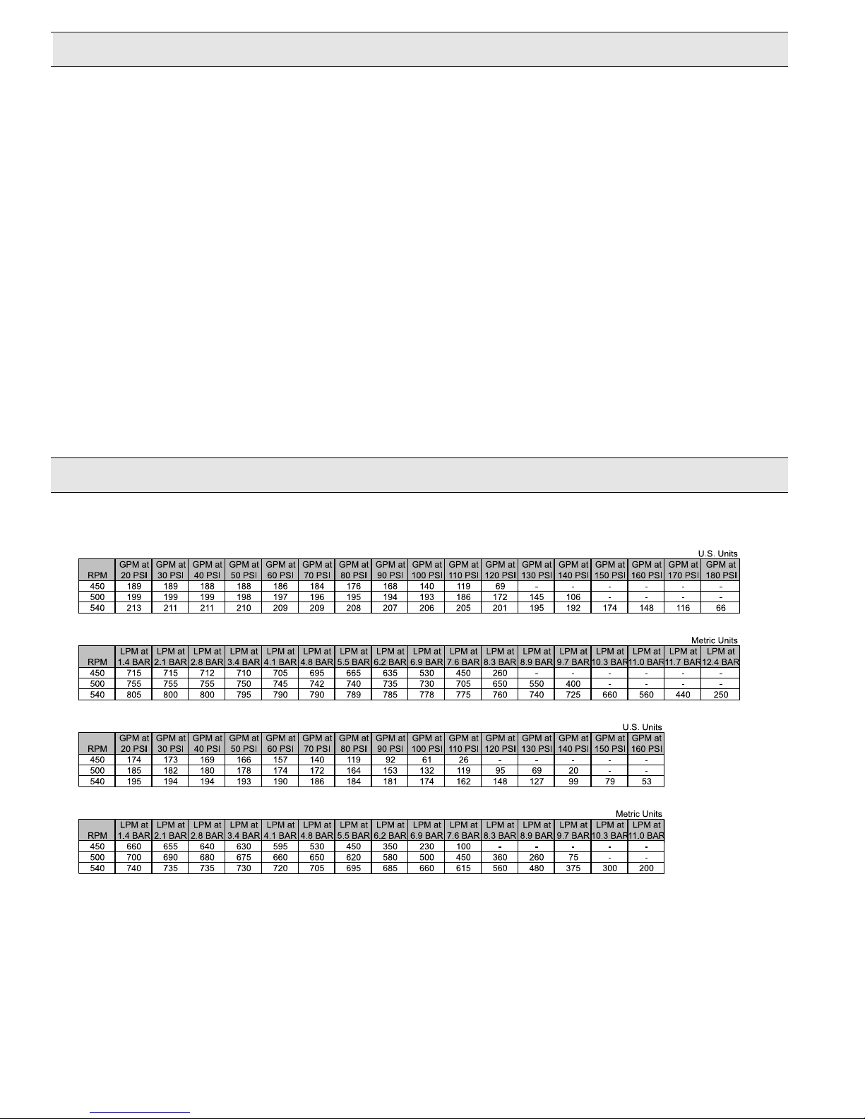
Performance-tested in Water
Model 9047C
Model 9047C
Models 9047C-SP, 9047C-BSP
Models 9047C-SP, 9047C-BSP
Performance Charts
L-1529 (12/11, Rev. C)
8
Page 9
9047 Series Pumps
10
8
9
6
3
5
11
7
4
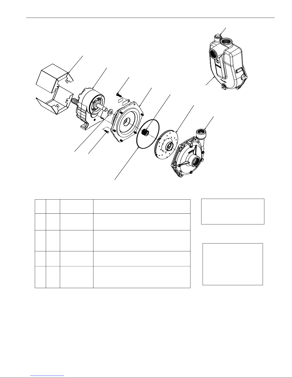
Ref. Qty. Part
No. Req'd. No. Description
1A 1 0153-9200C1 Pump Casing (with SS wear ring)
1B 1 0152-9275C2 Pump Casing (Self-Priming Model) - NPT
1C 1 0152-9275C3 Pump Casing (Self-Priming Model) - BSP
2 1 0404-9200P Impeller (CCW rotation)
3 1 0707-9200C1 Gas Engine Flange (machined)
4 1 1720-0180 O-ring
5 1 2120-0053 Mechanical Seal (Viton)
6 6 2210-0086 Hex Head Capscrew
7 4 2210-0098 Hex Head Capscrew
8 2 2840-0086 Shield, PTO Shaft
9 1 8000-0072-10 Gear Box - 10 oz. (9047C, 9047C-SP, 9047C-BSP)
9 1 8000-0072-18 Gear Box - 18 oz. (90030)
10 1 2406-0036 Pipe Plug
11 1 1410-0091 Slinger Ring
1B
1C
2
1A
Seal Kit No. 3430-0779
consists of:
(1) Ref. 4 O-ring and (1) Ref. 5
Mechanical Seal
NOTE: When ordering parts,
give QUANTITY, PART NUMBER,
DESCRIPTION, and COMPLETE
MODEL NUMBER. Reference
numbers are used ONLY to
identify parts in the drawing and
are NOT to be used as order
numbers.
9
L-1529 (12/11, Rev. C)
Page 10

Notes
L-1529 (12/11, Rev. C)
10
Page 11

Notes
11
L-1529 (12/11, Rev. C)
Page 12

Limited Warranty on Hypro/SHURflo Agricultural Pumps & Accessories
SPRAY & INJECTION TECHNOLOGIES GROUP
375 Fifth Avenue NW •New Brighton, MN 55112
Phone: (651) 766-6300
•
800-424-9776•Fax: 800-323-6496
www.hypropumps.com
Hypro/SHURflo (hereafter, “Hypro”) agricultural products are warranted to be free of defects in material and workmanship under
normal use for the time periods listed below, with proof of purchase.
- Pumps: one (1) year from the date of manufacture, or one (1) year of use. This limited warranty will not
exceed two (2) years, in any event.
- Accessories: ninety (90) days of use.
This limited warranty will not apply to products that were improperly installed, misapplied, damaged, altered, or incompatible with
fluids or components not manufactured by Hypro. All warranty considerations are governed by Hypro’s written return policy.
Hypro’s obligation under this limited warranty policy is limited to the repair or replacement of the product. All returns will be tested
per Hypro’s factory criteria. Products found not defective (under the terms of this limited warranty) are subject to charges paid by the
returnee for the testing and packaging of “tested good” non-warranty returns.
No credit or labor allowances will be given for products returned as defective. Warranty replacement will be shipped on a freight allowed
basis. Hypro reserves the right to choose the method of transportation.
This limited warranty is in lieu of all other warranties, expressed or implied, and no other person is authorized to give any other
warranty or assume obligation or liability on Hypro’s behalf. Hypro shall not be liable for any labor, damage or other expense, nor shall
Hypro be liable for any indirect, incidental or consequential damages of any kind incurred by the reason of the use or sale of
any defective product. This limited warranty covers agricultural products distributed within the United States of America. Other world
market areas should consult with the actual distributor for any deviation from this document.
Return Procedures
All products must be flushed of any chemical (ref. OSHA section 1910.1200 (d) (e) (f) (g) (h)) and hazardous chemicals must be
labeled/tagged before being shipped* to Hypro for service or warranty consideration. Hypro reserves the right to request a Material Safety
Data Sheet from the returnee for any pump/product it deems necessary. Hypro reserves the right to “disposition as scrap” products
returned which contain unknown fluids. Hypro reserves the right to charge the returnee for any and all costs incurred for chemical
testing, and proper disposal of components containing unknown fluids. Hypro requests this in order to protect the environment and
personnel from the hazards of handling unknown fluids.
Be prepared to give Hypro full details of the problem, including the model number, date of purchase, and from whom you purchased your
product. Hypro may request additional information, and may require a sketch to illustrate the problem.
Contact Hypro Service Department at 800-468-3428 to receive a Return Merchandise Authorization number (RMA#).
Returns are to be shipped with the RMA number clearly marked on the outside of the package. Hypro shall not be liable for freight
damage incurred during shipping. Please package all returns carefully
. All products returned for warranty work should be sent shipping
charges prepaid to:
HYPRO
Attention: Service Department
375 Fifth Avenue NW
New Brighton, MN 55112
For technical or application assistance, call the Hypro Technical/Application number: 800-445-8360, or send an email to:
[email protected]. T
o obtain service or warranty assistance, call the Hypro Service and Warranty number: 800-468-3428;
or send a fax to the Hypro Service and Warranty FAX: 651-766-6618.
*Carriers, including U.S.P.S., airlines, UPS, ground freight, etc., require specific identification of any hazardous material being shipped. Failure to do so
may result in a substantial fine and/or prison term. Check with your shipping company for specific instructions.
Printed in the USA
2011 Hypro
 Loading...