

Page 1
Series 5200 Big Twin® Piston Pumps
Form L-0225P
Installation, Operation, Repair and Parts Manual
10-05
Description
SERIES 5200C
Cast Iron Big Twin Piston Pump
Max. Flow Rate: ..... 6 gpm (5206) @ 600 rpm
10 gpm (5210)
Max. Pressure: ...................................400 psi
Max. Speed: ...........................800 rpm (5206)
600 rpm (5210)
Ports: ....................................... 3/4" NPT inlet
3/4" NPT outlet
Shaft: ..................................................1" solid
1-3/8" hollow shaft
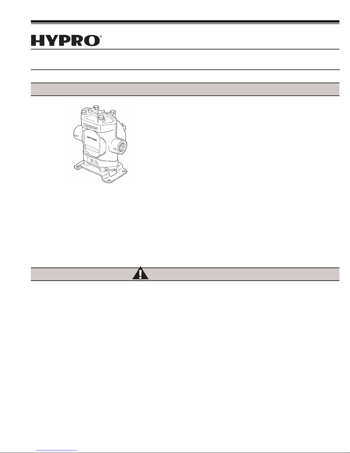
The Hypro Series 5200 Big Twin® piston pump is suitable
for applications in high pressure washers for industrial and
agricultural cleaning needs. It is also useful as a sprayer
pump to apply a wide range of chemicals.
The Series 5200 is constructed of cast iron body and
cylinder heads, unitized stainless steel valve assemblies
and double row ball bearing supported crankshaft. Three
cup materials are available to meet specific pumping needs.
They are:
Leather–for pumping aromatic solvents and other
chemicals damaging to rubber.
Fabric–for pumping most insecticides, herbicides and
fertilizers.
Buna-N Rubber–for pumping soap and detergent
solutions and some fertilizers.
Two crankshaft options are available—1" solid shaft for belt
and pulley or flexible coupling drive, or 1-3/8" hollow shaft
for direct mounting onto a 6-spline 540 rpm PTO shaft.
Safety Information
1. Warning: Do not pump flammable or explosive fluids
such as gasoline, fuel oil, kerosene, etc. Do not use
in explosive atmospheres. The pump should be used
only with liquids compatible with the pump component
materials. Failure to follow this warning can result in
personal injury and/or property damage and will void
the product warranty.
2. Be sure all exposed moving parts such as shafts,couplers
and adapters are properly shielded or guarded and that
all coupling devices are securely attached before applying
power.
3. Pumps mounted directly on to PTO shaft or other power
shaft must be prevented from rotating with the power
shaft by use of a torque arm. Pump must float freely on
the power shaft and must not be tied rigidly to equipment
on which it is mounted.
4. Do Not Exceed recommended speed, pressure and
temperature for pump and equipment being used.
5. Before Servicing, disconnect all power, make sure all
pressure in the system is relieved, drain all liquids from
the system and flush.
6. Secure the discharge lines before starting the pump. An
unsecured line may whip, causing personal injury and/or
property damage.
7. Check hose for weak or worn condition before each use.
Make certain that all connections are tight and secure.
8. Periodically inspect the pump and the system components.
Perform routine maintenance as required (see Maintenance
section).
9. Protect pump from freezing conditions by draining liquid
and pumping rust inhibiting antifreeze solution through
the system, coating the pump interior.
10. Use only pipe, hose and fittings rated for the maximum
psi rating of the pump.
11. Do not use these pumps for pumping water or other liquids
for human or animal consumption.
Page 2
Drive Source Installation
L
d
This manual will cover the installation of the basic drive
configurations available for the Hypro Big Twin Piston
pumps. Consult the manufacturer of your motor or engine
Belt/Pulley Drive Installation
Mounting Belts and Pulleys
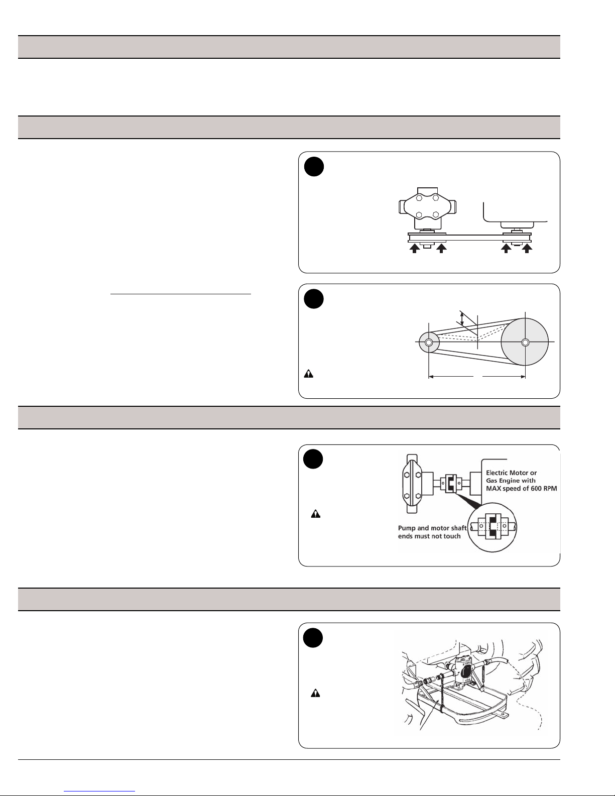
Mount pulleys as close to pump and motor engine shaft bearings
as possible. Check alignment with a straight edge as shown
in Fig. 1. Make sure that belt has proper tension. (Too much
tension will cause bearing wear; too little will cause slippage.)
See Fig. 2. Check with belt and pulley sources for specific
recommendation.
To figure proper diameter of pump pulley, multiply the
motor/engine rpm by the diameter of the motor/engine pulley
and divide that figure by desired pump speed.
Pump = Motor RPM x Motor Pulley Size
Pulley Size Desired Pump Speed
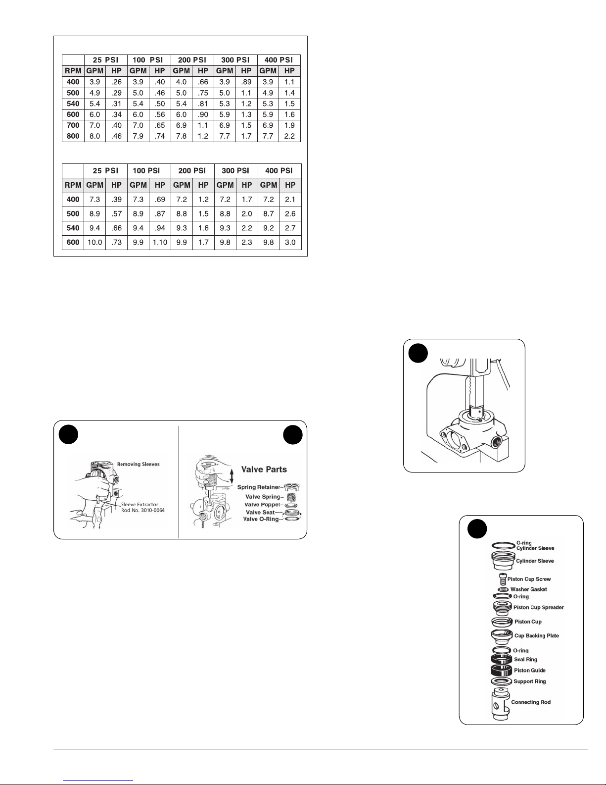
Refer to the pump performance chart on Page 5 to determine
the desired speed to obtain the desired maximum flow.
NOTE: Shaft rotation can be either clockwise or counter
clockwise.
for additional information. Read all instructions and general
safety information before attempting to install or operate the
pump.
1
Four po i n t s o f
cont a c t i n d i c a t e
alignment.
NOTE: Pump may
be mounted in other
or ien tat ion s with
respect to the motor
or engine
Push the belt midway between
2
the pulleys, check the deflection
(d) and adjust:
d = 0.016 x L
Caution:
For safety, always install a shield over
rotating shafts and belts.
Direct Drive - Flexible Coupling Installation
First, slide coupling ends onto motor/engine and pump shafts
as far as possible (Fig 3). Mount motor/engine and pump
onto base, shimming pump or power unit so that shafts are
aligned. Leave enough space between ends of shafts to
allow coupling disc to be inserted. When alignment is made,
slide coupling ends over coupling disc. Leave clearance
between coupling ends and center disc. Tighten screws in
both coupling ends. For electric motor drive, use couplings
rated at least twice the horsepower required to operate pump.
For gas engine drive, select couplings rated at three times
the required pump horsepower.
Direct Drive - Hollow Shaft Installation
Hollow shaft models may be mounted directly onto power
shaft — motor or engine shaft, truck or tractor PTO shaft.
Important: When direct mounting a hollow shaft pump,
Not rigidly mount the pump base. The pump must be allowed
to “float”. Secure a torque arm with a chain or flexible fastener
to the frame or base, directly below and in-line with the pump.
This prevents the pump from rotating with the shaft. Always
check to see if the pump will turn by hand to ensure that the
pump rotates freely. Do Not apply power to a pump where
the shaft doesn't rotate freely.
Do
3
Caution:
Fo r saf e t y, alw a ys
install a shield over
rotat ing shafts and
couplings
4
Caution:
Fo r sa f e ty, al w ays
install a shield over
rotat in g shafts and
couplings
-2-
Page 3
System Installation
Series 5200 Pump Hook-Up to
5
Boom for Chemical Spraying
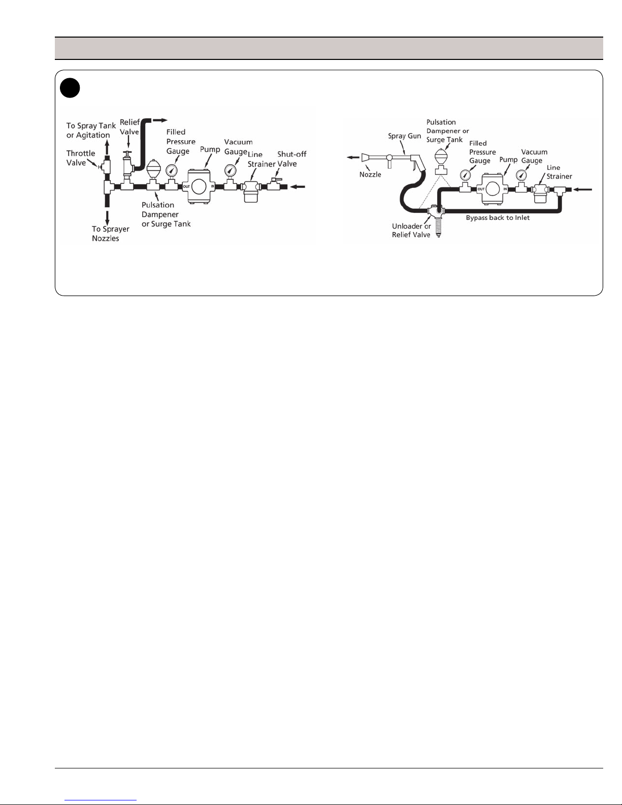
Note: A pulsation dampener such as our Model No. 3375-0017, 3375-0015 or surge tank Model No. 3375-0003 must be installed on the outlet side
for optimum performance and maximum life. For the proper operation of some unloader valves, it may be necessary to install a pulsation dampener
downstream from the unloader valve; however, for optimum system dampening, it may be installed upstream from the unloader valve provided that
the unloader valve will still function properly.
Piston Pump Installation
Accessories should be installed with solid piping and be
mounted as close to the pump as possible. Hose must be
used right after accessories. NOTE: If remaining installation is
solid piping, a two to four foot length of hose must be installed
between accessories and solid piping.
Hose
Selection of the right size and type of hose is vital to good
performance. Be sure to hook up to proper ports on pump (note
markings “IN” and “OUT” on pump castings).
Suction Hose
Always use genuine suction hose of at least the same inside
diameter as pump ports. Hose should have some elasticity, but
not overly soft so that it collapses. Use 3/4" (ID) hose or larger
for a Series 5200 pump. If suction hose is over 6 feet long on
Series 5200 use next larger size hose. Keep suction hose as
short as possible and restrictions such as elbows, check valves,
etc. at a minimum.
Discharge Hose
High pressure pumps require the use of special high pressure
discharge hose (2 rayon braid or equivalent). Use a hose rated
at least 50% greater than the highest operating pressure
required of pump. Example: If required pump pressure is 200
psi, use discharge hose rated at minimum of 300 psi working
pressure.
Unloader or Relief Valve
The unloader or relief valve has a very important safety function
in your piston pump hook-up. The valve protects the pump by
unloading or bypassing the pump’s flow when gun is shut off
or discharge is otherwise blocked.
Series 5200 Pump Hook-Up for
Pressure Washing
Strainers
Use a suction line strainer with an open screen area of at least
3 to 5 times the suction port area. For example, an area of
approximately 2-1/3 to 4 square inches for a 1" suction port. Be
sure the screen is suitable for the liquid being pumped. Keep
filter clean. A clogged strainer will cause cavitation, which usually
leads to a poor performance, wear and failure of pump parts.
Vacuum Gauge (Optional)
Pump should not be subjected to high suction line vacuums. To
check on this, install a vacuum gauge at pump inlet. Generally,
it should not read over 5 inches of mercury.
Suction Line Shut-Off
This suction line accessory allows the pump to be removed for
service without draining the tank. Be sure valve is open before
starting pump.
Surge Tank or Pulsation Dampener
This device absorbs the shock and smooths out the pump
discharge pulsations, providing smoother operation. A charge
of 50% of operating pressure is normally optimum. Note: A
surge tank or pulsation dampener is required on Series
5210 and optional on Series 5206.
Pressure Gauge/Dampener
Use gauge capable of reading double the pump working
pressure. Use a filled gauge or a gauge dampener to protect
the gauge needle against pressure surges to provide easier
reading and longer life.
Spray Gun
Use a Model No. 3381-0010 spray gun or a 3381-0013 Turbo
400 spray gun with the correct nozzle. For 5206 models use a
3385-3000 nozzle and for the 5210 models use a 3385-4000
to obtain a maximum pressure of 400 psi.
-3-
Page 4
Operation
C
H
D E
B
A
F G
Priming
If liquid is below level of pump, some means should be provided
in installation to prime pump — such as a Riser Pipe. If there is
a suction lift use a Foot Valve or Check Valve to hold prime. In
general, keep suction lift to minimum and avoid unnecessary
bends in suction line. Before starting pump, make sure air
bleeder valve or spray gun is open — or unloader/relief valve is
adjusted to its lowest pressure. After starting pump, open and
close gun several times if necessary to aid priming the pump.
If pump does not prime within a few seconds, stop motor and
inspect installation for suction line leaks or obstructions. Make
sure that strainer is not clogged. Be sure that suction line is not
obstructed, kinked or blocked.
If pump is to operate hours at a time, check frequently for:
1. Adequate liquid supply. Pump must not run dry for more
than 30 seconds.
2. Temperature rise. Overheating is harmful to bearings and
piston cups.
Care of Pump
Your pump will last longer and give best performance when
properly taken care of. Proper pump care depends a lot on the
liquid being pumped and when the pump will be used again.
Generally, after each use, flush pump with a neutralizing solution
for the liquid just pumped. Follow with a clear water rinse. This
is especially important for corrosive chemicals. Then flush out
pump with a 50% solution of automotive radiator anti-freeze
(ethylene glycol type such as Prestone, Zerex, etc.) containing
a rust inhibitor...or use a commercial rust-inhibitor such as
Fluid Film
.
While this flushing is not absolutely necessary for short periods
of idleness (as over night) it is good practice to clean the pump
after each use to prevent deposits from forming and damaging
the pump. The antifreeze not only coats the interior of the
pump with an inhibitor, but acts as a lubricant as well, keeping
the valves from sticking and protecting against any remaining
moisture freezing in cold weather.
For infrequent use and before long periods of storage, drain
pump thoroughly. Open any drain plugs, remove suction hose
from liquid and run pump “dry” from 0 to 30 seconds (not longer).
Flush with a 50% solution of anti-freeze and water. Then, plug
both ports to keep out air until pump is used again.
Lubrication
Use a small push-type grease gun to lubricate Hypro Series
5200 Piston Pumps. Do not use airpowered or hand lever
operated grease guns as they develop too much pressure
and may cause damage to the sealed cam bearing. Lubricate
a minimum every 100 hours or when bearing appears to need
grease. Use Moly-Lithium No. 2 wheel bearing grease.
Exception: In applications where FDA approval is required, use
one of these greases: Chevron FM#2, Mobile FM#2 Keystone
(Penwalt Corp.) Nevastane SP Medium.
Do not under-grease or premature bearing failure may result.
Do not grease excessively. Remove (do not WASH out) any
excess grease from pump cavity to prevent grease build-up.
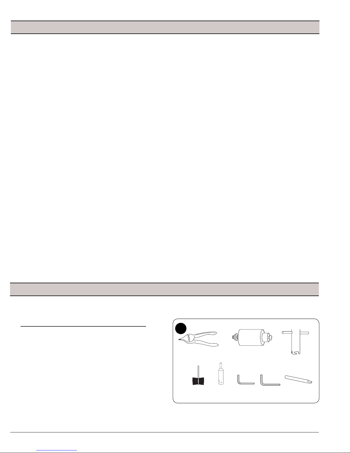
Recommended Repair Tools For Hypro Big Twin Piston Pumps
Ref. Description Part No.
A Internal External Pliers 3010-0084
B Valve Seat Extractor 3010-0130
C Valve Cage Extractor 3010-0052
D Wire Brush 3010-0066
E Wire Brush Holder 3010-0067
F Allen Wrench 3020-0009
G Allen Wrench 3020-0008
H Sleeve Extractor 3010-0064
Tool Box (Not Shown) 3010-0168
Repair Instructions
6
-4-
Page 5
Inspection of pump parts
Model 5206C Performance
Model 5210C Performance
Disassembly
1. Remove nameplate and both cylinder heads with a 9/16"
combination wrench or socket.
2. Remove both piston cap screws with 1/4" allen
wrench.
3. Remove piston cup spreader seal ring with O-ring piston
guide and support ring.
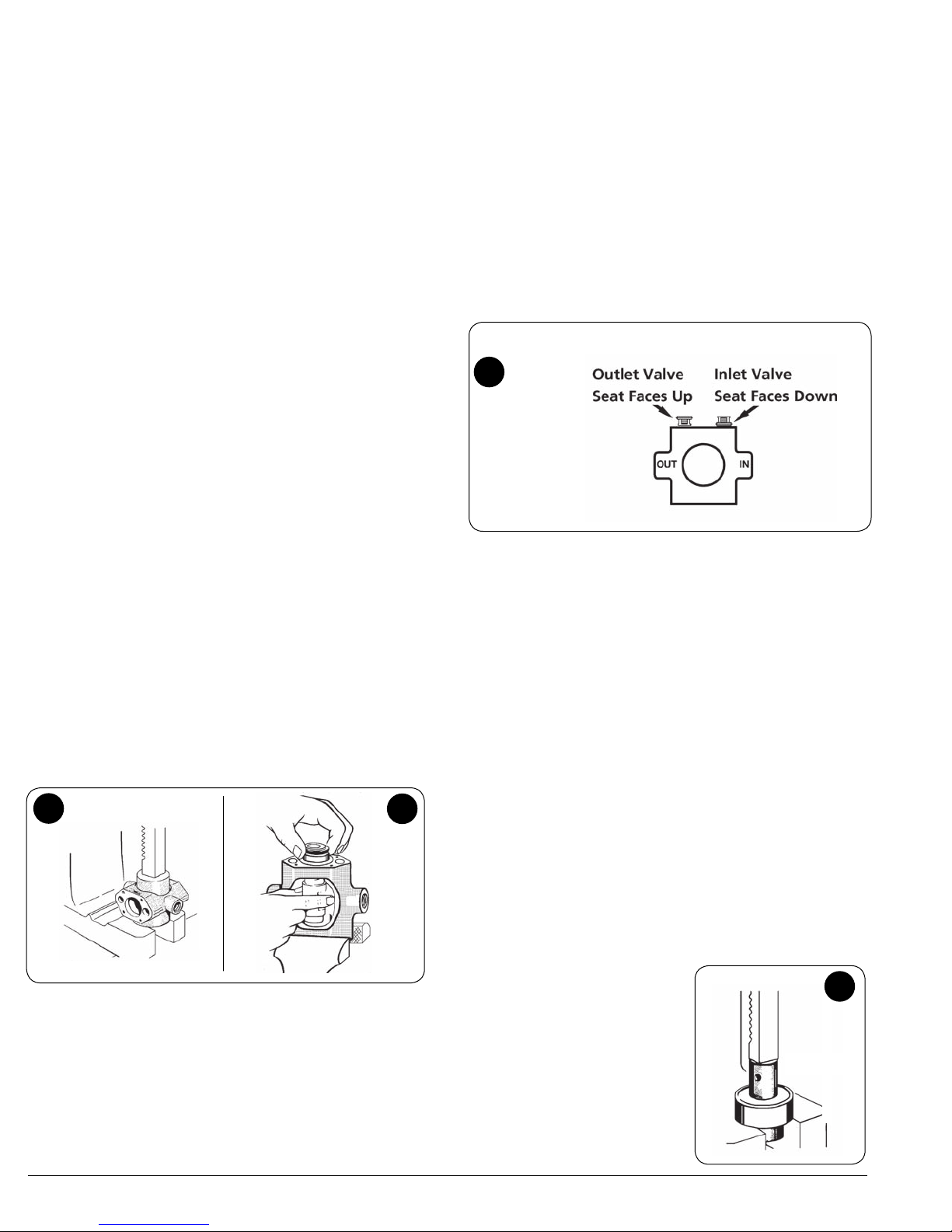
4. Place the body into a vise as shown in Fig. 7. With care,
drive out the cylinder sleeves using the sleeve extractor
tool and a hammer.
5. Remove connecting rod.
Before reassembling the pump, thoroughly inspect all parts,
with special consideration given to following points:
a. Inspect the pump body for erosion at all O-ring seal
points and in valve and sleeve holes. Check main bear
ing housing for proper bearing fit. Check for cracks at
the ports.
b. Check for excessive wear in the cylinder heads. This
can result from erosion and/or valve seat hammer.
c. Check crankshaft assembly for general wear. Rotate
main and cam bearing to check for roughness due to
moisture or lack of grease damage. If bearings do not
turn smoothly or appear to be damaged, they should
be replaced. See section on replacing bearings in this
manual.
d. Carefully inspect cylinder sleeves. Polish sleeves not
more than .008" — using No. 120 grit emery cloth. For
final finish use a fine No. 320 grit emery cloth. If at this
point all grooves have not been removed, replace the
parts.
Note: If there is some pitting only at the top of
the sleeves, they can still be used. Grooves are more
likely to be the problem here instead of pitting.
9
-
7
6. Remove the four valves, using the valve seat extractor
to pry out the seat (See Fig. 8). Use a valve cage
extractor tool to remove each spring retainer. Lift out
the other parts, using penetrating oil as necessary to
loosen parts.
7. Place the pump body onto an arbor press with the shaft
end of the pump up. Press the crankshaft and bearing
out of the pump body (See Fig. 9). The main bearing
will come out with the crankshaft.
8. Sand the body ends and cylinder heads (mating surfaces)
lightly to remove all foreign material. Use a belt sander,
flat sanding block or flat file.
9. With wire brush mounted in an electric drill, clean all
valve cavities, sleeve cavities and ports. Wash pump
body out with solvent and let dry.
8
e. Inspect the piston guides
for chips, cracks and
score marks. Compare
guides with new one,
If there is noticeable
amount of clearance
between the guide and
sleeve wall, the guide
should be replaced.
f. Check for erosion on
the underside of piston
cup screw head.
the condition of the
screws is very important
— if there is erosion or
grooves, leakage will
occur.
Note:
10
-5-
Page 6
g. Next check the connecting rod for wear. If there are
visible signs of wear or damage to the hard coating, the
connecting rod should be replaced. If there is more than
.005" of wear, the connecting rod should be replaced. A
worn connecting rod results in low volume, low pressure
and a hammering sound. If not replaced, this situation
will damage the cam bearing as well.
h. The valve seat, poppet, spring and guide in valve sets
should be carefully inspected for cracks, pitting, etc. and
replaced as necessary. Note in particular the seat and
matching poppet; replace both — as a set — if one new
part will not mate with other old part.
i. When repairing the Series 5200 pump it is usually a good
idea to replace the piston cups. Piston repair kits are
available with either leather, fabric (rubber impregnated)
or pure rubber (Buna-N) cups.
j. Inspect complete crankshaft assembly for general wear.
If the pump has had as much as 500 hours of use, it is
suggested to replace the assembly. If broken cam bearing
is found — the reason is usually that the pump has been
operating over the 400 psi maximum. Another possible
cause is that the pump has not been equipped with the
proper surge tank or pulsation dampener to smooth out
the pressure surges inherent in a large displacement
2-cylinder pump.
k. Check all fittings — make certain that all sizes are correct
for port size of the pump. Thoroughly inspect and clean
before reinstalling.
l. At this point all parts should have been inspected and
cleaned. All parts should now be oiled (particularly
the O-rings) and placed on a clean work bench for
reassembly.
Reassembly
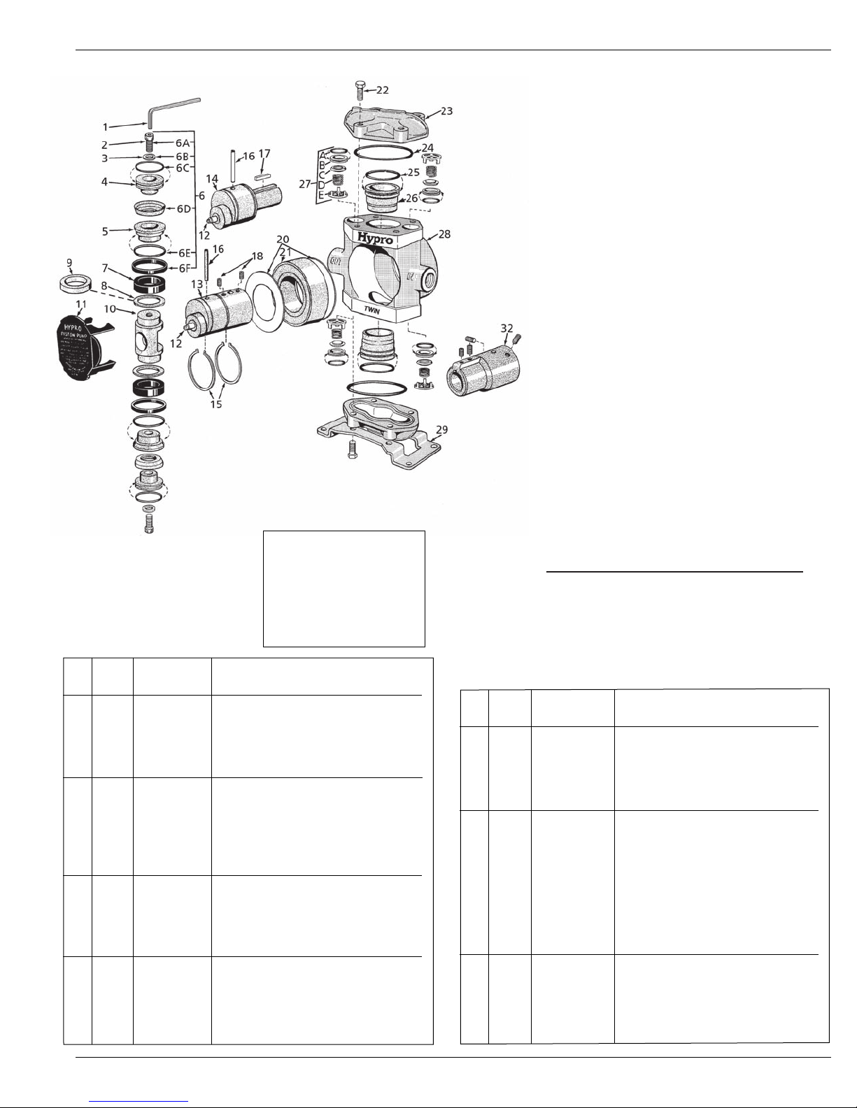
1. Using bearing seat tool, press the crankshaft assembly
into the pump body (see Fig. 11).
11
12
2. Insert connecting rod over the cam bearing.
3. Insert both cylinder sleeves with oiled O-rings in cylinder
bores.
4. Place pump in vise with ports horizontal (See Fig. 12).
Rotate crankshaft to raise connecting rod to its highest
position. Place support ring over top of connecting
rod.
5. Insert piston guide.
6. Place seal ring on top of guide.
7. Place cup backing plate with O-ring in place over seal
ring.
8. Insert piston cup.
9. Insert cup spreader with new O-ring in place. Press
into hollow of the piston cup.
10. Place a new copper washer gasket in the countersunk
screw hole of cup spreader.
11. Tighten piston cap screw securely with 1/4" allen
wrench.
12. Insert inlet and outlet valves with O-ring seals (See Fig.
13). These are identical, but in reverse positions.
13
Note:
Repeat for other
side of pump
Note the pump ports which are the “IN” and “OUT” sides.
13. Install cylinder head with a new O-ring seal and tighten
head bolts securely with a 9/16" wrench or socket.
14. Repeat steps 5 through 13 for assembling the other half
of the pump.
Note: Follow proper lubrication procedures as listed in
the Operating the Pump section of this manual
.
15. Replace the nameplate. The pump can now be tested
— pumping clear water.
Main Bearing Replacement
1. Remove set screws, bolts or keys from the shaft and
smooth off any burrs or rough spots
2. Remove retainer rings from shaft with external pliers.
For convenience, you can remove just the one closest
to the drive end of the shaft.
3. Support bearing in arbor press and press shaft out as
shown in Fig. 14.
4. New bearing is pressed on
in reverse manner. Front
retainer ring (closest to
cam bearing) should be in
place to provide a stop for
the bearing.
5. After bearing has been
pressed into place, install
the other retainer ring in
shaft groove with the ex
ternal pliers as before.
-
14
-6-
Page 7
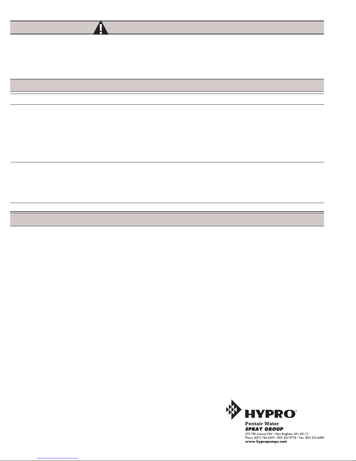
Models 5206C and 5210C
Piston Stack Parts Kits
Leather Cup Kit No. 3430-0037 (STD)
Consists of two each of the following parts: No.
2220-0013 Piston Cap Screw (Ref. 6A), No. 22700012 Washer (Ref. 6B), No. 1720-0030 O-Ring (Ref.
6C), No. 2150-0001 Leather Cup (Ref. 6D), No.
1720-0065 O-Ring (Ref. 6E) and No. 1440-0012
Seal Ring (Ref. 6F).
Fabric Cup Kit No. 3430-0039
Same as Leather Cup Kit except with two No. 21500012 Fabric Cups.
Rubber Cup Kit No. 3430-0189
Same as Leather Cup Kit except with two No. 21500042 Rubber Cups.
Crankshaft Assemblies
Sub-Assemblies
Include Grease Fitting (Ref. 12), Crankshaft with
cam bearing (Ref. 13 or 14) and Crankpin Retainer
(Ref. 16).
Complete Assemblies
Include Sub-Assembly components plus Retaining
Rings (Ref. 15), slinger rings (Ref. 20) and Bearing
(Ref. 21).
NOTE: When ordering parts,
give quantity, part number,
description, and complete
model number. Reference
numbers are used ONLY to
identify parts in the drawing and
are NOT to be used as order
numbers.
Ref. Qty. Part
No. Req'd. No. Description
1 1 3020-0008 Allen Wrench (Optional)
2 2 2220-0013 Piston Cap Screw
3 2 2270-0012 Washer
4 2 1830-0039 Piston Cup Spreader
5 2 1410-0054 Cup Backing Plate
6 1 3430-0037 Piston Stack Parts Kit with
Leather Cups (Standard)
6 1 3430-0039 Piston Stack Parts Kit with
Fabric Cups (Models 5200-F)
6 1 3430-0189 Piston Stack Parts Kit with
Buna-N Cups (Models 5200-R)
7 2 1440-0005 Piston Guide
8 2 1410-0018 Support Ring For 5210 Models Only
9 2 1410-0020 Support Ring For 5206 Models Only
10 1 0503-5200 Connecting Rod
11 1 0602-5200 Safety Cover
12 1 2405-0006 Grease Fitting Assembly
13 1 See Listing Crankshaft (Solid Shaft Models)
14 1 See Listing Crankshaft (Hollow Shaft Models)
15 2 1810-0001 Retainer Ring
16 1 1600-0013 Crankpin Retainer
Complete Pump
Sub-Assembly Assembly Model
PART NO. PART NO. Number
with 1-3/8" Hollow PTO Shaft (Ref. 13)
5503-5206 5501-5206 5206C-H
5503-5210 5501-5210 5210C-H
with 1" Solid Shaft (Ref. 14)
5003-5206 5001-5206 5206C
5003-5210 5001-5210 5210C
Ref. Qty. Part
No. Req'd. No. Description
17 1 1610-0005 Key (Solid Shaft Models)
18 2 2230-0003 Set Screw
20 2 1410-0006 Slinger Ring
21 1 2005-0002 Main Bearing
22 8 2210-0062 Cylinder Head Bolt
23 2 0203-5200CB Cylinder Head
24 2 1720-0028 O-Ring – for cylinder head
25 2 1720-0019 O-Ring – for cylinder sleeve
26 2 3550-0007 Cylinder Sleeve
27 4 3400-0038 Valve Assembly—Consists of:
O-ring (Ref. A), Valve Seat (Ref. B),
Valve Poppet (Ref. C),
Valve Spring (Ref. D)
and Valve Spring Retainer (Ref. E)
28 1 0100-5200C Body
29 1 1510-0024 Base
32 1 1320-0081 Adapter-Adapts 1
6-spline PTO hollow shaft. (Includes
set screws.)
" solid shaft to 1-3/8"
-7-
Page 8
Hazardous Substance Alert
1. Always drain and flush pump before servicing or disassembling
for any reason (see instructions).
2. Always drain and flush pumps prior to returning unit for
repair.
4. Before returning pump for service/repair, drain out all liquids
and flush unit with neutralizing liquid. Then, drain the pump.
Attach tag or include written notice certifying that this has
been done. Please note that it is illegal to ship or transport
any hazardous chemicals without United States Environmental
Protection Agency Licensing.
3. Never store pumps containing hazardous chemicals.
Troubleshooting
Symptom Probable Cause(s) Corrective Action(s)
Low Discharge Pump not primed See Priming section of this manual.
Clogged suction strainer Clear strainer screen.
Suction hose collapsed Replace suction hose with stronger wall hose.
Excessive vacuum on inlet Reduce inlet restrictions by eliminating items
such as elbows, valves or too small of inlet hose.
Pump running at wrong speed Check speed of pump and adjust accordingly.
Valves worn or hung-up Inspect valves and replace if necessary.
Low Pressure Unloader or Relief Valve set improperly Readjust unloader or relief valve.
Nozzle worn or damaged Check nozzle and replace.
Valves worn or hung-up Inspect valves and replace if necessary.
Insufficient power from gas Check performance chart to find proper HP needed
engine or electric motor for flow and pressure desired.
Liquid leaking from center of pump Seals worn Replace with new seal kit.
Limited Warranty on Hypro Pumps and Other Hypro Products
Hypro warrants to the original purchaser of its products (the “Purchaser”) that such products will be free from defects in material and workmanship under normal use for the period
of one (1) year for all products except: oil crankcase plunger pumps will be free from defects in material and workmanship under normal use for the period of five (5) years, and
accessories will be free from defects in material and workmanship under normal use for the period of ninety (90) days. In addition, Hypro warrants to the purchaser all forged
brass pump manifolds will be free from defects in material and workmanship under normal use and from damage resulting from environmental conditions for the life of the pump.
“Normal use” does not include use in excess of recommended maximum speeds, pressures, vacuums and temperatures, or use requiring handling of fluids not compatible with
component materials, as noted in Hypro product catalogs, technical literature, and instructions. This warranty does not cover freight damage, freezing damage, normal wear and
tear, or damage caused by misapplication, fault, negligence, alterations, or repair that affects the performance or reliability of the product.
This warranty is exclusive. Hypro makes no other warranty, express or implied, including but not limited to any warranty of merchantability or fitness for a particular
purpose.
Hypro’s obligation under this warranty is, at Hypro’s option, to either repair or replace the product upon return of the entire product to the Hypro factory in accordance with the
return procedures set forth below. This is the exclusive remedy for any breach of warranty.
In no event shall Hypro be liable for any incidental or consequential damages of any kind, whether for breach of any warranty, for negligence, on the basis of strict
liability, or otherwise.
Return Procedures
All pumps or products must be flushed of any chemical (ref. OSHA Section 0910.1200 (d)(e)(f)(g)(h)) and hazardous chemicals must be labeled before being shipped*
to Hypro for service or warranty consideration. Hypro reserves the right to request a Material Safety Data sheet from the Purchaser for any pump or product Hypro deems
necessary. Hypro reserves the right to “disposition as scrap” pumps or products returned which contain unknown substances, or to charge for any and all costs incurred for
chemical testing and proper disposal of components containing unknown substances. Hypro requests this in order to protect the environment and personnel from the hazards
of handling unknown substances.
For technical or application assistance, call the Hypro Technical/Application number: 1-800-445-8360.
To obtain service or warranty assistance, call the Hypro Service and Warranty number: 1-800-468-3428;
or call the Hypro Service and Warranty FAX: (651) 766-6618.
Hypro may request additional information, and may require a sketch to illustrate the problem.
Contact the factory to receive a return material authorization before sending the product. All pumps returned for warranty work should be sent shipping charges prepaid to:
HYPRO
Attention: Service Department
375 Fifth Avenue NW
New Brighton, Minnesota 55112
*Carriers, including U.S.P.S., airlines, UPS, ground freight, etc., require specific identification of any hazardous
materials being shipped. Failure to do so may result in a substantial fine and/or prison term. Check with your
shipping company for specific instructions.
Printed in the USA
2005 Hypro
-8-
 Loading...