

Page 1

Model 3300-0102 & 3300-0103 High Flow
Balanced Pressure Regulator Valves
Form L-1523
11/09
Installation & Operation Instructions
Installation
As a relief valve, this valve should be placed in an area that remains pressurized when the gun is shut off.
As a pressure regulator, the valve maintains the pressure in the system (even during flow changes). In this condition,
always use a suitable safety valve. If the bypass is directed directly into the pump, caution should be taken to avoid
excessive water temperature increases.
Operation
IMPORTANT:
The bypass port is at the bottom. The inlet port is on the side.
The bypass should be returned to a baffled tank for turbulence control.
Pressure Adjustment/Setting
As a relief valve, the adjustment has to be made in such a way that the pressure setting is not higher than the system’s
working pressure.
As a pressure regulator, adjust the valve when the system is pressurized and the gun is open. As the adjustment cap is
turned, there should be a corresponding change in pressure. To increase the pressure, turn the cap clockwise; to
decrease the pressure, turn the cap counterclockwise. Once the desired pressure is reached, tighten the ring nut to lock
the cap in place.
Specifications for 3300-0102
Max. Flow Pressure Range Max Temp. Inlet Port Bypass Port Dimensions
Standard
Metric 208 LM 18-138 BAR 85º C 3/4” NPT 1/2” NPT 159 x 50 x 38 mm
55 GPM 260-2000 PSI 185º F 3/4” NPT 1/2” NPT 6.25” x 2.00” x 1.50”
Specifications for 3300-0103
Standard 55 GPM 260-2000 PSI 185º F 1” NPT 1” NPT 6.25” x 2.90” x 1.65”
Metric 208 LM 18-138 BAR 85º C 1” NPT 1” NPT 159 x 74 x 42 mm
Order Information
Part No. Description
3300-0102 3/4” NPT Inlet x 1/2” NPT Bypass Model
3300-0103 1” NPT Inlet x 1” NPT Bypass Model
3430-0747 Piston and Seat Repair Kit
roubleshooting
T
alve is installed improperly (inlet & bypass may be reversed).
Valve chatters
Valve continually bypasses
V
V
Valve is missing its orifice washer.
alve is improperly set; repeat adjustment process.
V
Seat or piston worn; replace as needed.
alve is improperly set; repeat adjustment procedure.
Leaking out the top of valve O-ring and piston are worn or cut. Install repair kit.
Page 2
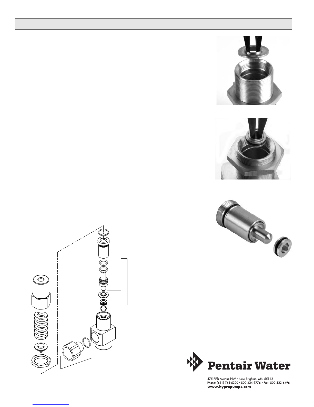
Instructions / Parts Drawing
FLOW TECHNOLOGIES GROUP
I
nstallation Instructions for Piston Seal Kit No. 3430-0747
1. Remove the adjustment cap from the top of the valve assembly.
2. Once cap is removed, the spring and spring plate can be removed.
. Using a .625 (5/8”) hex wrench, unscrew and remove the old sleeve and
3
piston assembly.
4. If the orifice washer didn’t come out with the sleeve assembly, use a valve
extractor tool (Hypro P/N 3010-0057), to reach down inside the body. Place
the extractor inside the orifice hole, expanding the tool, and then pull up,
removing the SST orifice washer as shown in Figure 1.
so do not discard it.)
5. Using the same extractor tool, reach down inside the body and remove the
seat by placing the extractor inside the seat hole, expanding the tool, and
then pulling up, removing the SST seat as shown in Figure 2.
6. Reassemble the new 3430-0747 kit in the reverse order as disassembly.
7. See Figure 2 for proper assembly direction of the new SST seat ring.
Seat must be installed with identification ring up as shown.
8. Orifice washer must be reassembled after seat and before installation of
new sleeve assembly or valve operation will be compromised.
NOTE:
(This part is re-used
Fig.1
Fig. 2
• O-rings on seat and outer sleeve should be lubricated prior to assembly to
ensure proper sealing.
• Piston and sleeve assembly should not be disassembled for any reason.
It is lubricated at the factory and should remain assembled as a unit.
Piston and Seat
Repair Kit
Part No. 3430-0747
No. 3430-0747 Kit
3300-0103 Model Only
Hypro 2009
Printed in the USA
 Loading...