

Hypro 1802C, 1803C, 1804C, 1805C, 1806C Installation, Operation, Repair And Parts Manual
...Page 1
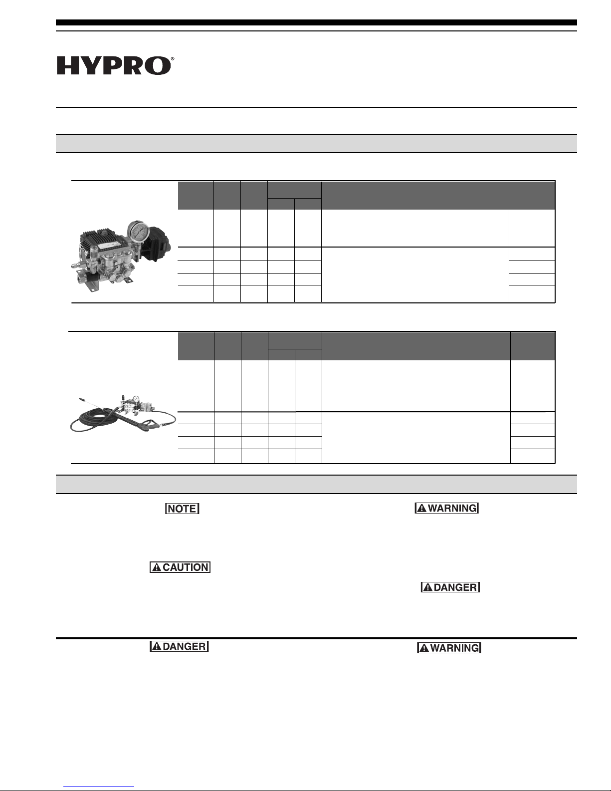
Hydraulically-Driven Pressure Washer
Models 1802C, 1803C, 1804C, 1805C, 1806C,
1807C, 1824C, 1825C, 1826C and 1827C
Form L-0560PW
Installation, Operation, Repair, and Parts Manual
Description
Hydraulically-Driven Pressure Washers
Model Max. Max. Estimated
Number GPM PSI
1803C 3.0 1000 5.0 1300 Forged Brass Head Triplex Pump with 28 lbs.
1805C 3.0 1500 8.0 1900 Forged Brass Head Triplex Pumps with 26 lbs.
1807C 3.0 2000 11.0 1300 hydraulic motor, chemical injector, 26 lbs.
1825C 4.0 1500 8.5 2000 adjustable unloader, gauge, 3⁄4" GH input, 33 lbs.
1827C 4.0 2000 8.5 2000
Hydraulic Motor
Requirements
GPM PSI
Description Weight Ea.
hydraulic motor, adjustable unloader, gauge,
1
⁄2" NPT input, 3⁄8" quick disconnect output
3
⁄8" quick disconnect output 33 lbs.
Hydraulically-Driven Pressure Washers with Hose and Gun Assembly
Model Max. Max. Estimated
Number GPM PSI
1802C 3.0 1000 5.0 1300 Forged Brass Head Triplex Pump 38 lbs.
1804C 3.0 1500 8.0 1900 Forged Brass Head Triplex Pumps with hydraulic 41 lbs.
1806C 3.0 2000 11.0 1300 motor, chemical injector, adjustable unloader, 26 lbs.
1824C 4.0 1500 8.5 2000 gauge
1826C 4.0 2000 8.5 2000 and 50 ft. hose and gun assembly 49 lbs.
Hydraulic Motor
Requirements
GPM PSI
Description Weight Ea.
with hydraulic motor, adjustable unloader,
1
gauge,
⁄2" NPT input,3⁄8" quick disconnect output,
and 50 ft. hose and gun assembly
3
⁄4" GH input, 3⁄8" quick disconnect output, 49 lbs.
2/08
0
General Safety Information
Notes are used to notify of installation, operation, or
maintenance information that is important but not
safety related.
Caution is used to indicate the presence of a hazard,
which will or can cause minor injury or property
damage if the notice is ignored.
Do not pump flammable or explosive fluids such as
gasoline, fuel oil, kerosene, etc. Do not use in
explosive atmospheres unless the Pump is
properly grounded and the proper drive is used.
The Pump should only be used with liquids
compatible with the Pump materials. Failure to
follow this notice can result in severe personal
injury and/or property damage and will void the
product warranty
.
arning denotes that a potential hazard exists and
W
indicates procedures that must be followed exactly
to either eliminate or reduce the hazard, and to
avoid serious personal injury
, or prevent future
safety problems with the product.
Danger is used to indicate the presence of a hazard
that will result in severe personal injury
, death, or
property damage if the notice is ignored.
The sound pressure level of the Pump may exceed
80dBA. Observe all safety precautions when
operating the Pump within close proximity for
extended periods by wearing hearing protectors.
Extended exposure to elevated sound levels will
result in permanent loss of hearing acuteness,
tinnitus, tiredness, stress, and other effects such as
loss of balance and awareness.
Page 2
Do not pump at pressures higher than the maximum
recommended pressure.
Operate the Pump between a temperature range of
45oto 140oF [7oto 60oC].
Make certain that the power source conforms to the
requirements of your equipment.
Provide adequate protection in guarding around the
moving parts such as shafts and pulleys.
Secure the discharge line before starting the pump.
An unsecured discharge line may whip, resulting in
ersonal injury and/or property damage.
p
heck all hoses for weak or worn condition before
C
each use. Make certain that all connections are tight
and secure.
Periodically inspect the pump and the system
components. Perform routine maintenance as
required.
Disconnect the power before servicing.
Release all pressure within the system before
servicing any component.
Drain all liquids from the system before servicing.
Hazardous Substance Alert
Always drain and flush the pump before servicing.
Always drain and flush the pump prior to returning
the Pump to Hypro for repair.
Never store a pump containing hazardous materials.
Prior to returning a pump for service or repair, drain
all liquids and flush the pump with a neutralizing
fluid; then, drain the pump again, and attach a tag or
written notice certifying that this procedure has been
done.
Use only pipe, hose, and hose fittings rated for
maximum rated pressure of the pump or the
pressure at which the pressure relief valve is set at.
Do not use used pipe.
Do not use these pumps for pumping water or other
liquids for human or animal consumption.
It is illegal to ship or transport any hazardous
chemical without United States Environmental
Protection Agency licensing.
Never use your hand to check the condition of
hydraulic lines or hoses. If hydraulic fluid penetrates
the skin, get medical help immediately. Failure to get
proper medical help may result in loss of limb or life.
The safest way to check hydraulic lines or hoses is
by holding a piece of cardboard next to the hydraulic
line or hose.
Hypro’s Hydraulically-Driven Pressure Washer can be
installed on tractors with Closed Center and Load
Sensing Hydraulic Systems, or on Custom Open Center
Hydraulic Systems.
The required inlet conditions for the water pump can vary
from the flooded suction of a water tank to pressure from
a city water supply. The water supply must be capable
of supplying more than 4.0 gpm of water flow to meet the
pump requirements.
Installation Requirements
The pump comes equipped with an unloader valve and
bypass system rated for 2000 psi. When the trigger of
the gun is in the OFF position, the unloader allows water
to recirculate back through the pump. A thermal relief
valve is included to keep the pump from overheating
when it is in the bypass mode with the gun trigger in the
OFF position. For long pump life, do not allow the pump
to run more than five minutes with the gun trigger in the
OFF position.
2
Page 3
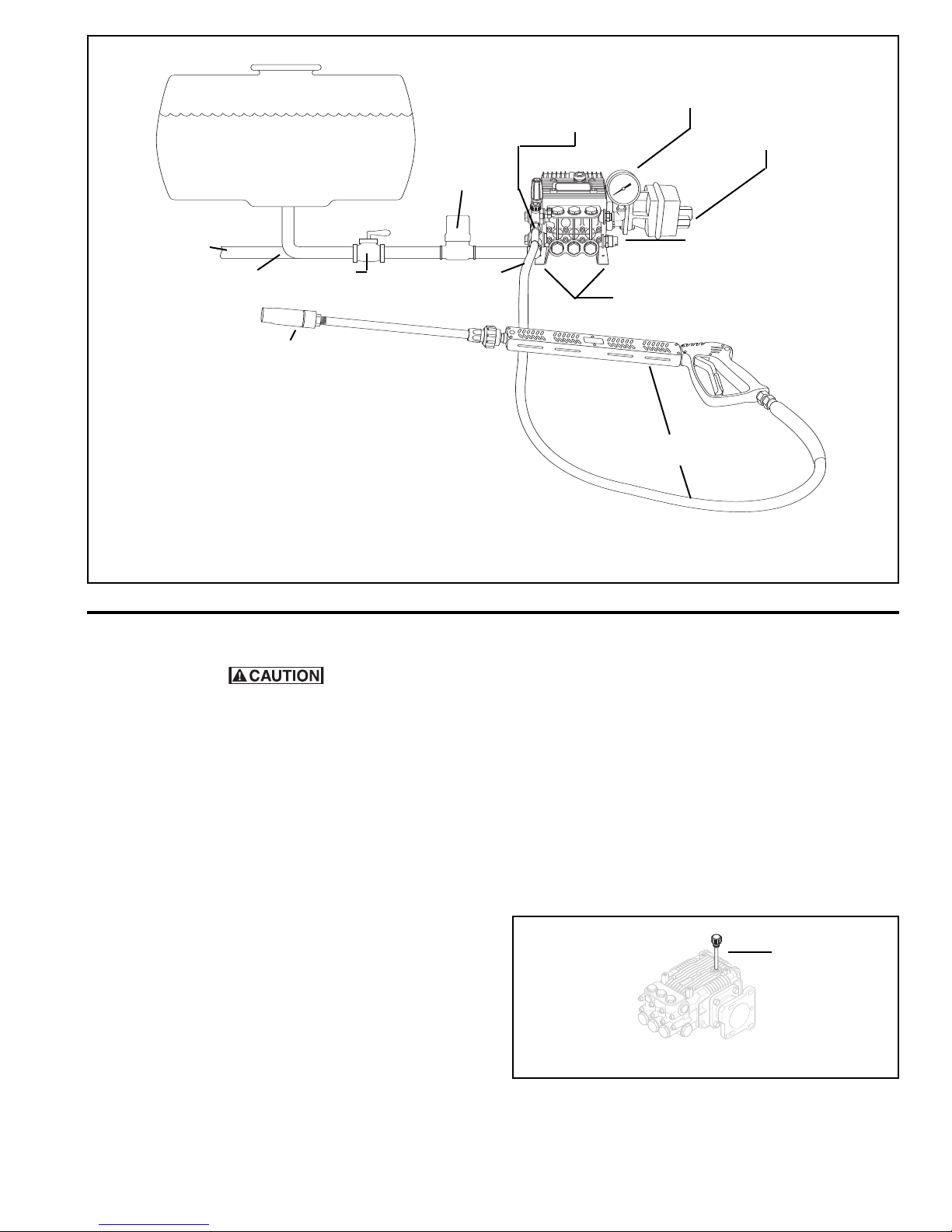
Fresh Water
Flooded Section
3/4" Strainer
80 Mesh
P/N 3350-0035,
3350-0045,
3350-0035A
or equivalent
Hydraulic Quick
Disconnect
matches
female end
on Kit 8000-0030 &
8000-0049
5,000 psi
Gauge
Hydraulic Input
1/2" NPT (F)
Municipal Water
Supply Access
3/4" Hose
• Gun, Lance, Nozzle & Hose Assembly includes 50'
pressure hose, gun, wand, nozzle, and female quick
disconnect.
• Tank is mounted even or above the pump.
Mount the tank higher if the inlet hose length is over 15 ft.
• Never run the pump dry.
• If suction inlet hose is more than four feet long, use next
larger size.
Full-Flow, 3/4"
Shut-Off Valve
Hi-Lo
Spray Nozzle
3/4" Garden Hose
Adapter
Figure 1
Hydraulically-Driven Pressure Washer Hookup
Unloader Valve Instructions
The Unloader is factory set to a maximum of 2000
psi [138 BAR]. Do not tamper with the Unloader
Valve settings or with the Locking Ring. Hydraulic
System damage may result if the Unloader is
adjusted outside the range of 2000 psi [138 BAR].
The Unloader Valve is factory tested and preset to
2000 psi [138 BAR]. Adjustment is necessary only if the
unloader is not functioning properly.
1. For priming, the Spray Gun and Hose Assembly (Kit
8000-0030) should be detached from the pump at
the Quick Disconnect (See Figure 1).
Thermal Relief Valve
Four
25/64 Dia.
Holes
Spray Gun
and Hose
5. The standard Pressure Washer is equipped with an
adjustable cleaning angle nozzle. The cleaning
angle may be varied throughout its range by rotating
the black outer body clockwise (CW) or
counterclockwise (CCW).
6. Your Pressure Washer is equipped with the optional
Detergent Injection System. The nozzle must be set
in Low Pressure Mode to activate the injector and
draw soap. For rinsing, the nozzle should be set in
High Pressure Mode. Pushing the black nozzle
body forward places the nozzle in the Low Pressure
Mode. Pulling the black nozzle body back places the
nozzle in the High Pressure Mode.
Before Starting Up
2. Start the Pump and run it until it is fully primed, with
water flowing freely out of the Quick Disconnect.
Then, stop the Pump and reattach the Spray Gun
and Hose Assembly at the Quick Disconnect (See
Figure 1).
3. Pull the Gun Trigger, restart the Pump, and observe
the pressure. The Hydraulic System and/or Bleeder
Bypass Screw may require adjustment to obtain the
proper pressure of 2,000 psi [138 BAR] (Refer
Hydraulic System Operation for further information).
4. Open and close the Pressure Wash Gun several
times to check the unloading pressure and Unloader
Valve function.
Check oil level
Figure 2
Check that the oil is at the correct level using the
Dipstick, and topping off if necessary (See Figure 2). Use
Hypro Oil (part no. 2160-0038). Hypro oil is specially
formulated, high grade, non-detergent, SAE 30 weight oil
designed to prolong Pump life.
3
Page 4
Change the oil after 40 hours of break-in operation.
hereafter, change the oil every year or 500 hours,
T
whichever comes first.
are of the Pump
C
After each use, flush the pump with a neutralizing
solution for the liquid pumped. Follow this with a clear
water rinse. For storage under freezing conditions, flush
Hydraulic System Operation
the pump with a 50/50 solution of automotive-type
ntifreeze and water.
a
Bypass Operation
uring Bypass Operation (when water is diverted back to
D
the pump inlet side) a temperature rise occurs. A
Thermal Relief Valve is provided to maintain the
maximum water temperature at 145° F [63° C].
Hydraulic Systems
There are three types of Hydraulic Systems: Open
center, Closed Center (Pressure Compensated), and
Closed Center Load Sensing (Flow and Pressure
Compensated).
Open Center Systems
In an Open Center System, the hydraulic pump puts out
a constant flow. If the Pump puts out more than the
Motor can use, a portion of the oil must be bypassed
around the Motor. The Bleeder Bypass Screw allows the
fluid to bypass around the Motor. When the oil is
bypassed around a loop and does no work, the energy
put into it by the Pump turns into heat. Therefore, this
should only be used on smaller Open Center Systems
where the amount of oil that must be bypassed is
minimal.
Closed Center (Pressure Compensated) Systems
Closed Center (Pressure Compensated) Systems have a
Variable Displacement Pump that will deliver flow at the
necessary rate to maintain a specified pressure. The
Flow Control Valve should be installed at the Motor Inlet
to control the flow according to the Model requirements.
Closed Center Load Sensing Systems (Flow and
Pressure Compensating)
The Closed Center Flow Compensated System is a
variation of the Pressure Compensated System,
designed primarily for more efficient operation and the
generation of less heat. It works on the principle of
maintaining a constant pressure drop from the pump to
the working port of the Selector Valve. Any variation in
demand at the Motor will cause a change in flow. The
system senses this change in flow due to the change in
pressure drop across the Valve and causes the pump to
compensate by varying the Pump flow
Do not bypass oil. Use a Flow Control at the Motor
Inlet to control the flow and speed of the motor.
Hydraulic Oil
The specifications for the Hydraulic-Driven Pressure
Washer where compiled using Mobil DTE-26 hydraulic
oil at a temperature of 140° F [60° C]. Using other type
of oil and different temperatures will result in different
flow requirements to replicate these Pressure Washer
performance specifications. These specifications are a
guide for initial start-up.
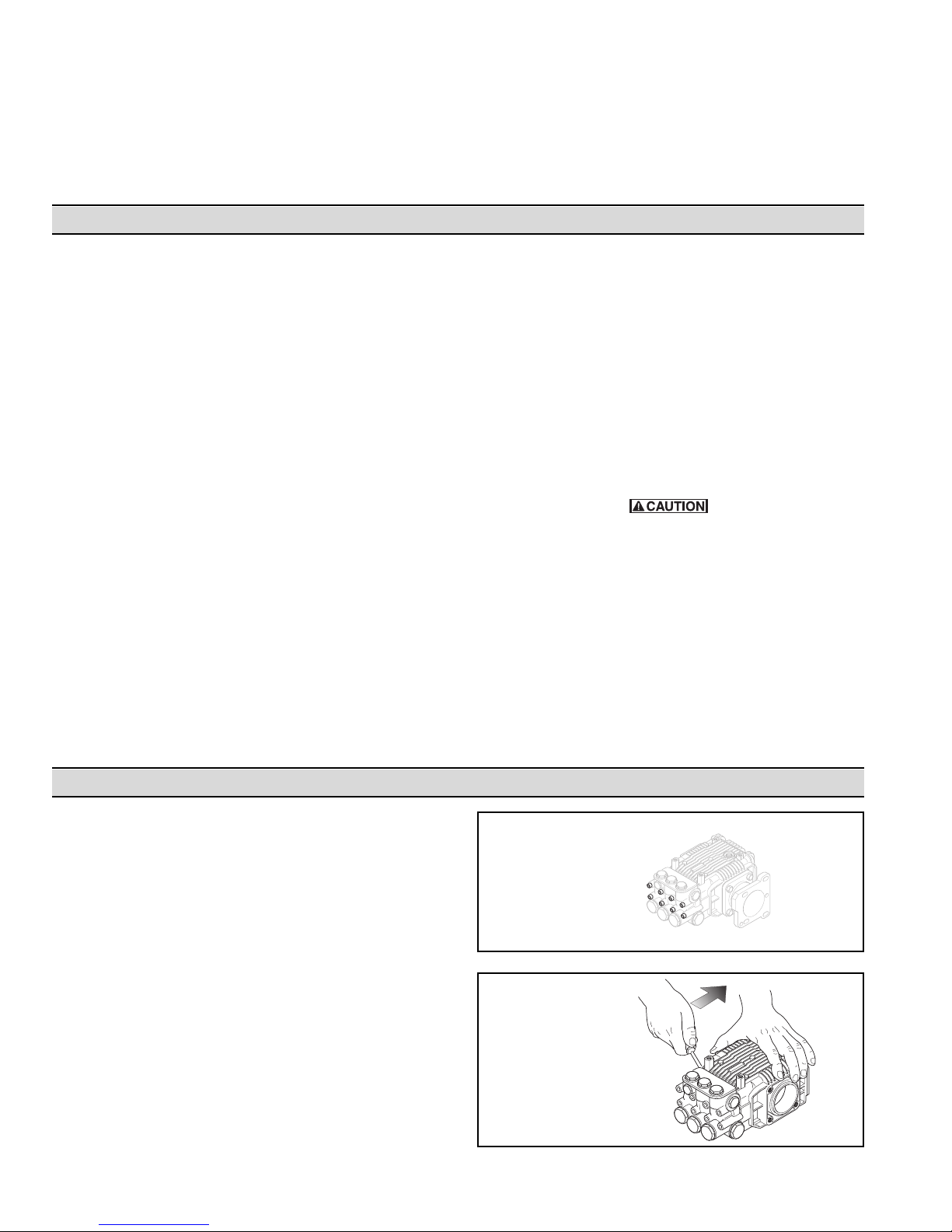
Plunger Replacement.
Using a metric allen wrench, remove the Socket
1.
Head Cap Screws securing the Pump Head to the
Pump Body (See Figure 3).
2. While turning the Crankshaft, use two screwdrivers to
carefully pry between the Pump Head and Pump
Body to remove the Pump Head (See Figure 4).
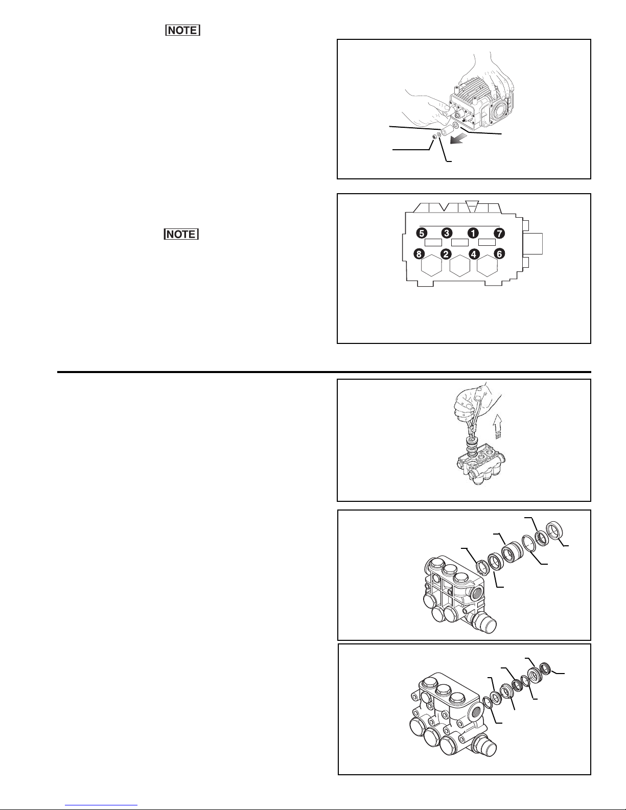
3. Remove the plunger Retaining Nut and the Plunger
Retaining Nut W
asher (See Figures 5).
4. Slide the Plungers off the Piston Guides (See
Figure 5).
5. Remove and discard the O-rings (See Figure 5).
Remove the Slinger Ring (See Figure 5).
6.
Pump Repair Instructions
Remove
Socket Head Cap
Screws
Figure 3
While turning the
crankshaft, use
screwdrivers to pry
the pump head off.
Figure 4
4
Page 5
pply a thin film of oil to the new O-rings and
A
lungers before installing them.
P
7. Inspect the Plungers for cracking and replace them if
damaged installing new O-rings and Slinger Rings at
he same time.
t
. Install the Plunger Retaining Nut Washers: then,
8
apply a drop of blue thread locking compound to the
threads of the Plunger Retaining Nuts and install
them.
9. Tighten the Plunger Retaining Nuts to 88 in. lbs.
[9.8 Nm] torque (See Figure 5).
If you are replacing the Packings, proceed with
Packing Replacement.
Plunger
Plunger Retaining
Nut
Figure 5
linger Ring
S
Plunger Retaining
Nut Washer
10. Lubricate the Plungers and install the Pump Head
onto the Plungers: then, push the Pump Head
against the Pump Body.
11. Install the Socket Head Cap Screws removed in
Step 1; then tighten them as shown in Figure 6 to 88
in. lbs. [9.8 Nm] torque.
Packing Replacement
Water leakage between the pump head and pump body
indicates the plunger packings require replacement.
1. Using a metric allen wrench, remove the socket
head Cap Screws securing the pump head to the
pump body (See Figure 3).
2. While turning the crankshaft, use two screwdrivers
to carefully pry between the pump head and pump
body to remove the pump head (See Figure 4).
3. Using Extractor Pliers, remove the Seal Retainers
and Seals (See Figure 7).
4. Using a small blade knife, remove the Seals from
the Seal Retainers.
Figure 6
Using Extractor
Pliers to remove
Seal Retainers
and Seals
Figure 7
Models
1806C & 1807C
Packing
placement
e
R
Alternately and evenly tighten the
Socket Head Cap Screws to
88 in. lbs. [9.8 Nm] torque
Seal
Piston Guide
Suppor
t Ring
Seal
Seal
O-ring
5. Lightly lubricate and install new seal kit items in the
order shown in Figures 8 and 9.
Lightly lubricate the plungers and install the pump
6.
head onto the plungers: then push the pump head
against the pump body.
7. Install the socket head Cap Screws removed in
Step
1; then tighten them as shown in Figure 6 to
88 in. lbs. [9.8 Nm] torque.
Figure 8
1826C & 1827C
e
R
Figure 9
5
Models
Packing
placement
Seal Retainer
Seal
Gasket
Seal
O-ring
Seal Retainer
O-ring
Page 6
Valve Replacement
Erratic or low-pressure operation may be the result of
debris in the Valves or Worn Poppets and/or Seats.
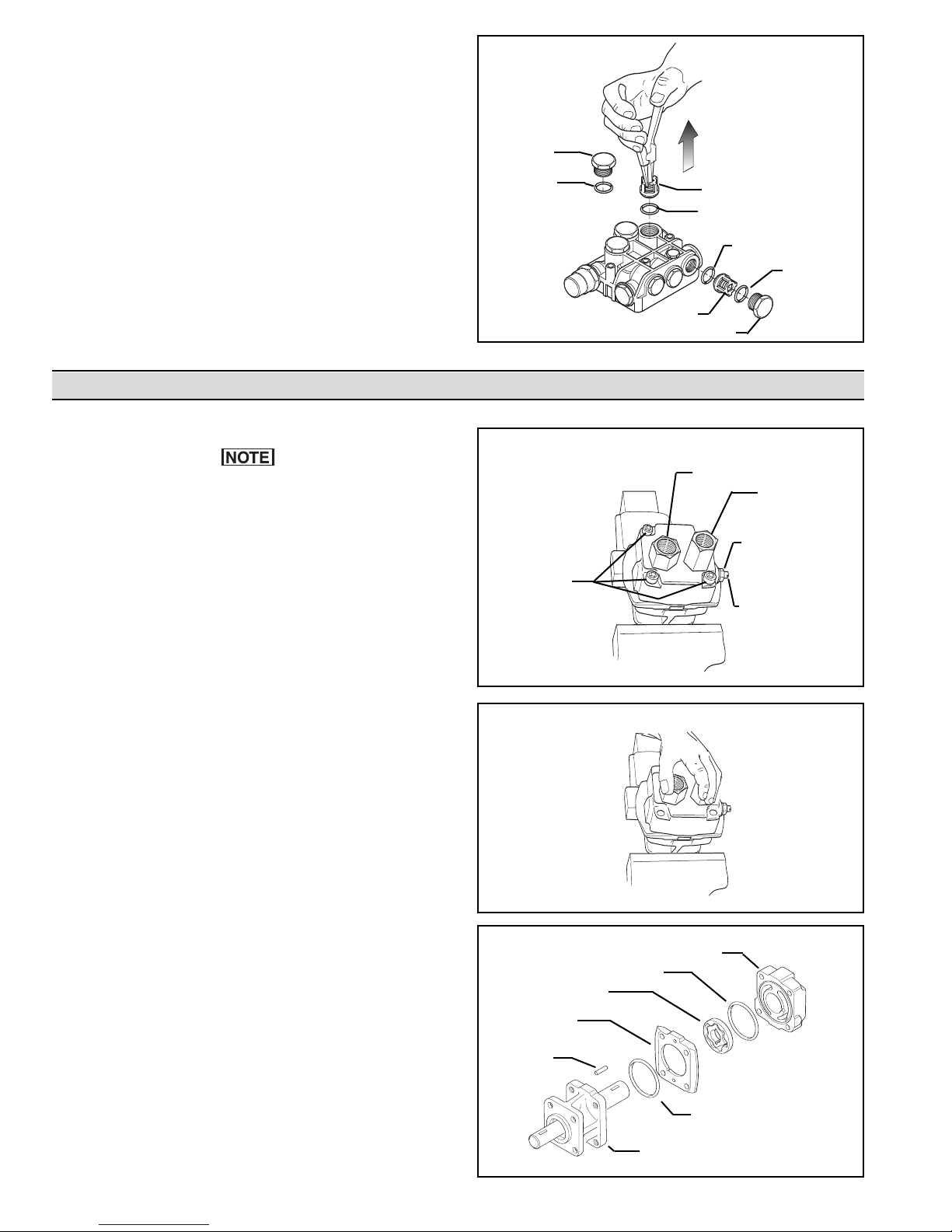
. Remove the Plugs; then using needle nosed pliers,
1
remove the Valves (See Figure 10).
2. Remove and discard the old O-ring (See Figure 10).
3. Inspect the Valves for signs of debris and/or wear. If
worn or damaged, replace the Valves and install new
O-rings (See Figure 10).
4. Install the Plugs and tighten them to 25 ft. lbs.
[33.9 Nm] torque (See Figure 10).
Hydraulic Motor Repair Instructions
Hydraulic Motor Disassembly
The work area should be kept as clean as possible to
prevent contamination of parts.
Plug
O-ring
Figure 10
Valve
O-ring
Valve
Plug
Pressure Port
Adapter
O-ring
O-ring
Tank Port
Adapter
1. Place the Hydraulic Motor in a vise (See Figure 11).
2. Using a large crescent or 1-1/16" box wrench,
loosen but do not remove the Tank Port Adapter and
Pressure Port Adapter (See Figure 11).
3. Using a 9/16" box wrench, loosen the Nut on the
Bypass Adjusting Screw (See Figure 11).
4. Using a small screwdriver, remove the Bypass
Adjusting Screw from the Hydraulic Motor. (This will
remove the Adjusting Screw, Lock Nut, Washer, and
Gasket.) (See Figure 11.)
5. Using a 1/4" allen wrench, remove the Socket Head
Cap Screws from the Motor End Plate (See
Figure 11).
6. Grasp the Motor End Plate and Gerotor Housing by
the Tank Port Adapter and Pressure Port Adapter,
and with a rocking motion, remove the Motor End
Plate and Gerotor Housing; then, remove the Tank
Port Adapter and Pressure Port Adapter (See
Figure 12).
7. Remove the Gerotor Housing and both components
of the Gerotor (See Figure 13).
8. Remove both components of the Gerotor from the
Gerotor Housing (See Figure 13).
Bypass Adjusting
Screw Nut
Socket Head
Cap Screws
Bypass Adjusting
Screw
Figure 11
Figure 12
Motor End
Plate
O-ring
Gerotor
Gerotor
Housing
Roll
Pin
Using a flat instrument, such as a knife, remove the
9.
O-ring from the Motor End Plate and Body (See
Figure 13).
6
Figure 13
O-ring
Motor
Body
Page 7
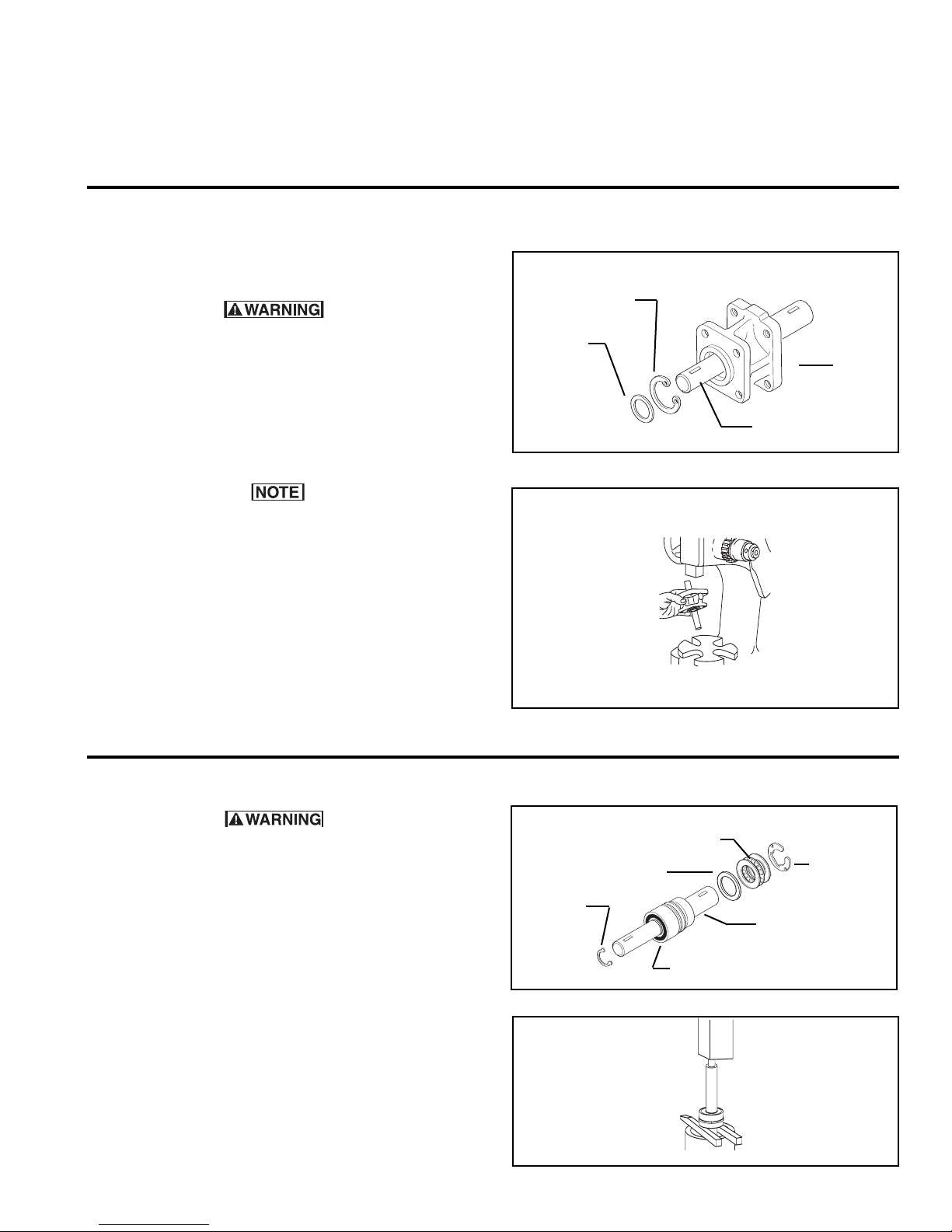
10. Remove the Roll Pin from the Shaft (See Figure 13).
11. Inspect the Motor End Plate, Body, and Gerotor
Housing for signs of wear and/or gouging. If signs of
ear or gouging are present in both the Motor End
w
Plate and Body, the Hydraulic Motor is not reparable.
If gouging has occurred in the Motor End Plate,
emoving the Shaft Assembly from the Motor Body
R
1. Remove the Rubber Slinger Ring from the Motor
Shaft (See Figure 14).
Special attention should be exercised when working
with retaining rings. Always wear safety goggles
when working with spring or tension loaded
fasteners or devices.
Body, or Gerotor Housing, the part that is worn must
be replaced. If the Gerotor Housing is damaged, the
Gerotor parts must also be replaced.
2. While the hydraulic Motor is disassembled, clean all
1
parts in a solvent bath.
Internal
Retaining
Ring
Slinger
Ring
Front
Motor
Body
2. Remove the Internal Retaining Ring securing the
Ball Bearing and Shaft Assembly to the Motor Body
(See Figure 14).
If the Ball Bearing is binding against the internal
retaining ring so that the internal retaining ring
cannot be easily removed, place the motor body on
the arbor press support fixture with the ball bearing
side up. Gently press against the shaft to relieve
pressure of the ball bearing pressing against the
internal retaining ring.
3. Place the body in the support fixture and position it
on the arbor press; then press the Shaft Assembly
out of the Motor Body (See Figure 15).
Hydraulic Motor Shaft Disassembly and Repair
Special attention should be exercised when working
with retaining rings. Always wear safety goggles
when working with spring or tension loaded fasteners
or devices.
1. Remove the Large Retaining Ring from the Shaft (See
Figure 16).
2. Remove the Thrust Bearing (Thrust Bearing and two
Thrust Bearing Races) from the Shaft (See
Figure 16).
Figure 14
Figure 15
Retaining
Ring
Figure 16
Thrust Bearing
and Races
Seal
Spacer
Shaft
Ball Bearing
Ball Bearing and
Shaft Assembly
Large
Retaining
Ring
Shaft
3. Remove the Retaining Ring next to the Shaft Ball
Bearing (See Figure 16).
4. Remove the Bearing from the Shaft by placing the
Shaft in the pipe support fixture. Place the two bars
provided in the repair kit opposite each other and
Figure 17
7
Page 8
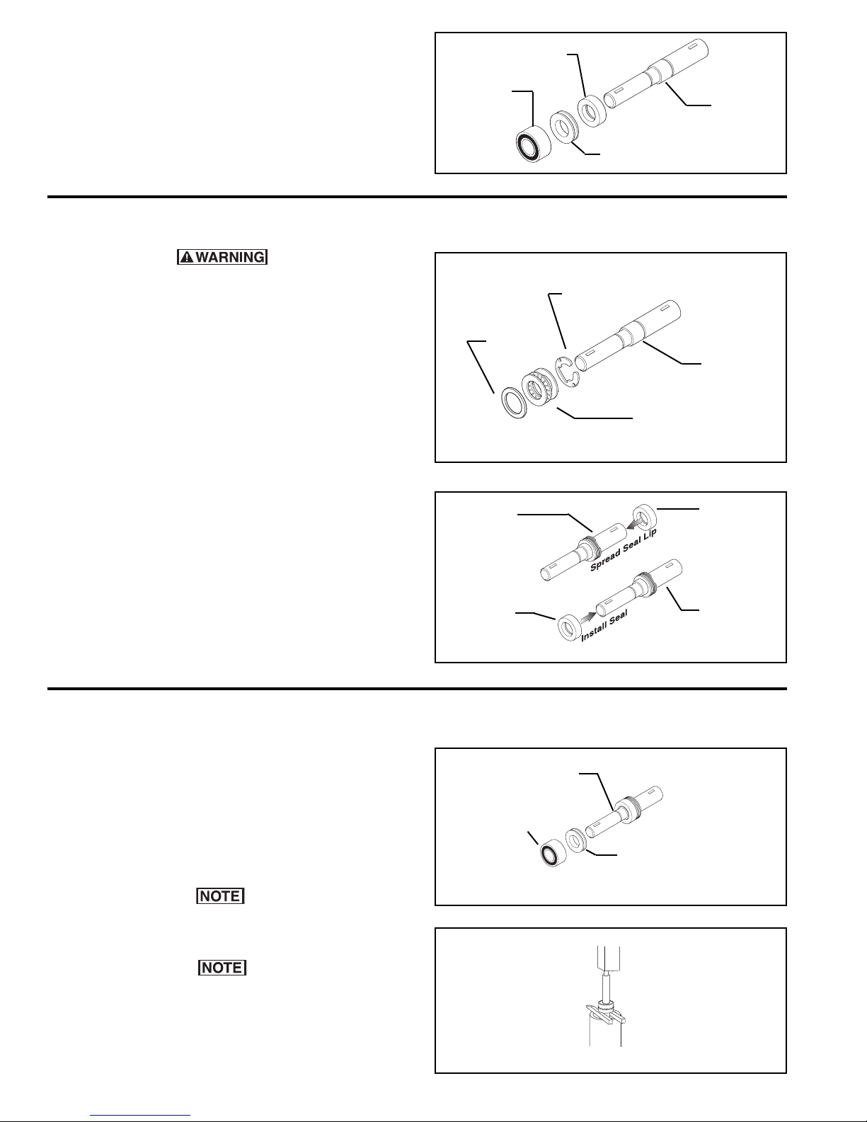
between the Seal on the Shaft and the support
fixture. Using an arbor press, press the Shaft
through the bearing, seal spacer, and seal (See
Figures 17 and 18).
5. Inspect the sealing area of the Shaft and other Shaft
Assembly components for signs of wear and replace
them if necessary.
Shaft Seal Installation
Shaft
Ball Bearing
Figure 18
Seal
Shaft
Seal Spacer
Special attention should be exercised when working
with retaining rings. Always wear safety goggles
when working with spring or tension loaded
fasteners or devices.
1. Install the Large Retaining Ring; then, slide the
Thrust Bearing and Races, and Seal Spacer onto the
Shaft (See Figure 19).
2. The sealing lips on the new Seal must be expanded
to fit on the Shaft. Press the Seal onto the large end
of the Shaft with the Seal Lip facing out. Do not
push the Seal past the keyway on the Shaft (See
Figure 20).
3. Once the Seal Lip has been expanded, remove the
Seal from the Shaft.
4. With the Seal Lip facing the large end of the Shaft,
slide the Seal over the smaller end of the Shaft, and
gently push it onto the large end of the Shaft until it
is seated against the Seal Spacer (See Figures
19 & 20).
Seal
Spacer
Figure 19
Shaft
Seal
Figure 20
Large
Retaining
Ring
Shaft
Thrust Bearing
and Races
Seal
Shaft
Shaft Bearing Installation
Install the Spacer Ring and Ball Bearing onto the
1.
Shaft (See Figure 21).
Insert the Shaft into the support fixture. Place the
2.
two support bars opposite each other and between
the Bearing and the fixture. Place them on an arbor
press and carefully press the Shaft down allowing
just enough room for the Retaining Ring next to the
Bearing to be installed (See Figure 22).
Make sure the spacer ring between the seal and the
bearing is free floating (not binding).
If the Main Needle Bearings in the Hydraulic Motor
require replacement, a new body an/or end plate,
with the main needle bearing already installed must
be used. If this occurs, check other internal parts of
the motor for damage or wear
.
Shaft
Ball Bearing
Spacer Ring
Figure 21
Figure 22
8
Page 9
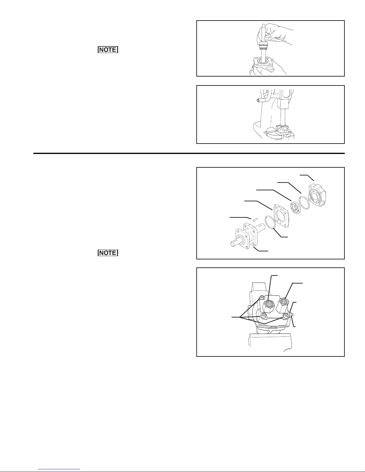
Installing the Shaft Assembly into the Motor Body
. Place the Shaft Assembly into the Motor Body
1
Bearing Bore (See Figure 23).
he Shaft Assembly and Motor Body Bearing Bore
T
must be aligned prior to pressing the Shaft
Assembly into the Motor Body Bearing Bore.
Misalignment will result in pinched Spacer Rings.
2. An unthreaded section of pipe (1" Dia X 4" long) is
needed to support the Outer Bearing Race of the
Shaft Ball Bearing. Place this pipe over the Shaft
Assembly; then, using an arbor press, press the
Shaft Assembly down until the Retaining Ring can be
installed in its groove in the bearing bore of the
Motor Body (See Figure 24).
Reassembly of the Remaining Hydraulic Motor Parts
1. Place the Motor Body in a vise with the large end of
the Shaft facing up.
2. Coat the new o-ring with a thin film of oil; then, install
the o-ring in the Motor Body (See Figure 25).
3. Install the Roll Pin on the Shaft. Place the Inner
Gear of the Gerotor onto the Shaft, making sure the
Gerotor Slot lines up with the Roll Pin in the Shaft
(See Figure 25).
The Roll Pin Key can slide up behind the inner gear
of the gerotor when the gear is installed. Make sure
the key is visible in the slot after the gear is in place.
Install the outer portion of the Gerotor
4.
, making sure
the Gerotor is centered within the O-ring groove in
the Motor Body (See Figure 25).
5. Lightly lubricate the area between the inner and
outer Gerotor and Gerotor Housing with hydraulic or
mineral oil.
Figure 23
Figure 24
Roll
Pin
Figure 25
Socket Head
Cap Screws
Gerotor
Gerotor
Housing
O-ring
Motor
Housing
Pressure Port
Motor End
Plate
O-ring
Adapter
Bypass Adjusting
Tank Port
Adapter
Bypass Adjusting
Screw Nut
Screw
6. Install the Gerotor Housing, making sure the Pins in
the Gerotor Housing line up with their respective
holes in the Motor Body
.
7. Coat the new O-ring with a thin film of oil; then,
install the O-ring on the Motor End Plate.
8. Place the End Plate on the Gerotor Housing, making
sure the holes in the End Plate line up with the Pins
in the Gerotor Housing.
9. Install the four Socket head Cap Screws in the Motor
End Plate; then, using a 1/4" allen wrench,
alternately and evenly tighten them to 15 ft. lbs. [20.3
Nm] torque (See Figure 26).
Figure 26
10. Put the Thread Seal Gasket on from the slotted end of
the Bypass Adjusting Screw leaving four threads
showing beyond the
Thread Seal Gasket (See Figure
26).
11. Install the Washer and Nut onto the Bypass
Adjusting Screw; then, install the Bypass Adjusting
Screw into the Motor Plate (See Figure 26).
a. For Closed Center Hydraulic Systems, turn the
bypass adjusting screw in until it bottoms out in
the end plate; then, using a 9/16" box wrench,
tighten the nut.
9
Page 10
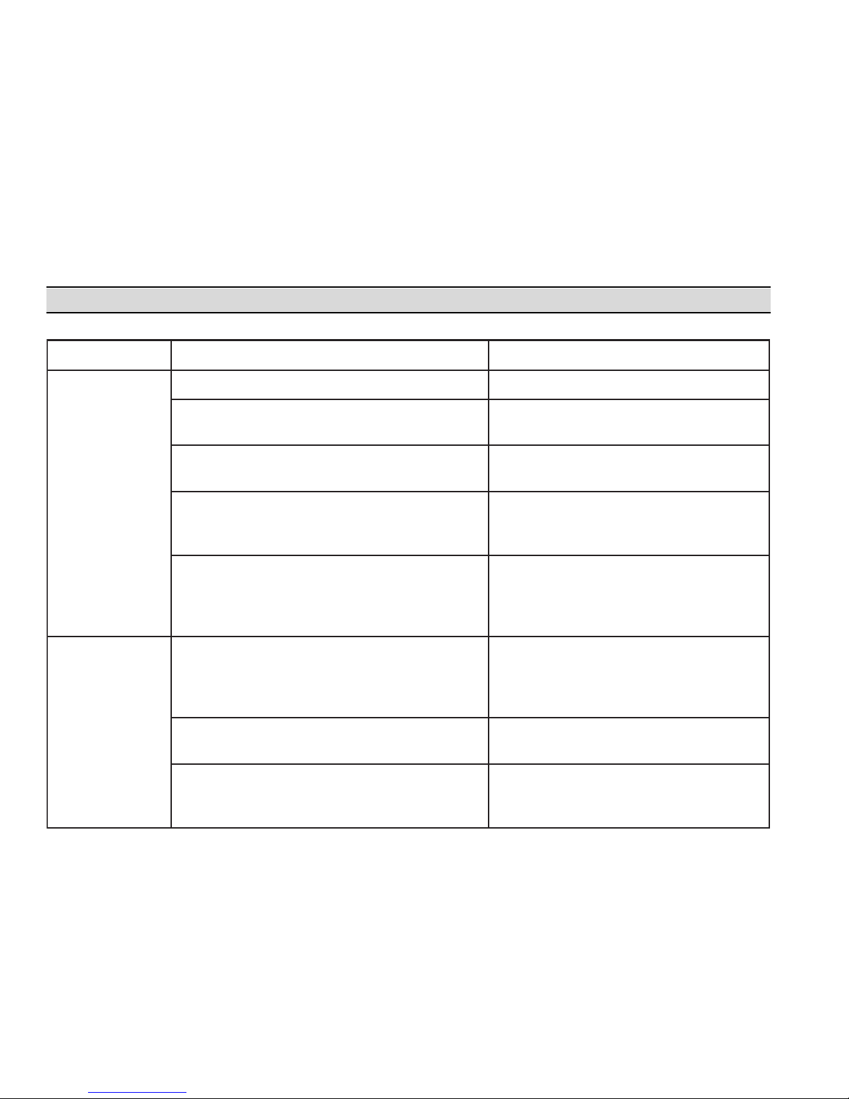
motpmySesuaCelbaborPnoitcAevitcerroC
.egrahcsidwoL
.demirptonsipmuPehTpmuPehtemirP
.eniLnoitcuSehtniskaelriA telnIehtlaeserdnaskaelriarofkcehC
.sgnittiF
.reniartSeniLdeggolcrodekcolB ynaevomerdnareniartSehttcepsnI
.neercSreniartSehtmorfsirbed
.eniLnoitcuSdespallocroezisrednU emasehtebdluohseniLnoitcuSehT
fotroPtelnIehtnahtregralroretemaid
.pmuPeht
ciluardyHehtniwercStnemtsujdAssapyB
.tesylreporptonsirotoM
wercStnemtsujdAssapyBehtnruT
ciluardyHehtfoedisehtnodetacol(
situptuoderisedehtlitnuesiwkcolc)rotoM
.deniatta
metsySciluardyH
.gnitaehrevo
ootssapybottessiwercStnemtsujdAssapyB
.liohcum
wercStnemtsujdAssapyBehtnruT
ciluardyHehtfoedisehtnodetacol(
situptuoderisedehtlitnuesiwkcolc)rotoM
.deniatta
nidellatsnineebsahecifirOgnireteMreporpmI
.troPerusserPeht
.ecifirOgnireteMezisreporpehtllatsnI
.llamsootsiezisesoHciluardyH hcni2/1tsaeltaebtsumesoHciluardyH
smetsySretneCnepOegralroF.retemaid
.retemaidhcni4/3tsaeltaebtsumti
.
b. For Open Center Hydraulic Systems, turn the
Bypass Adjusting Screw in until it bottoms out in
the End Plate; then, turn it back out 1-1/2 turns.
ighten the Nut while holding the Bypass
T
Adjusting Screw with a screwdriver; the
hydraulic Motor will then have to be readjusted
to the tractor system,
12. Replace the O-rings in both Port Adapters.
13. Install and tighten the Pressure Port Adapter; then
install and tighten the Tank Port Adapter (See
Figure 25).
Troubleshooting
14. Remove the Hydraulic Motor from the vise; then, turn
the Motor Shaft by hand to check for binding, the
Motor Shaft should turn freely.
5. Install the Slinger Ring over the Motor Shaft.
1
16. Using the four Hex Head Bolts, secure the Hydraulic
Motor to the Pump Mounting Flange.
10
Page 11
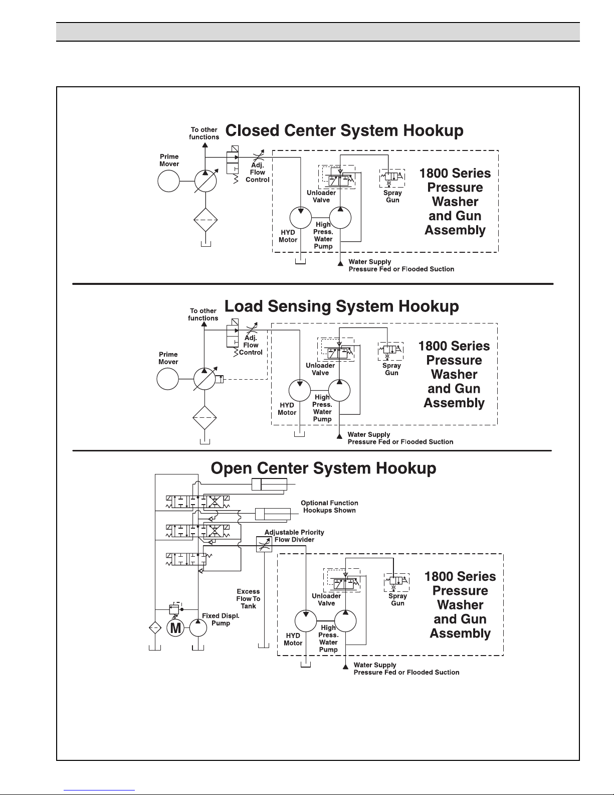
Typical Hydraulic Circuit Schematics for Hydraulic-Driven Pressure Washers
Figure 27
Typical Hydraulic Circuit Schematics for Hydraulic-Driven Pressure Washers
11
Page 12
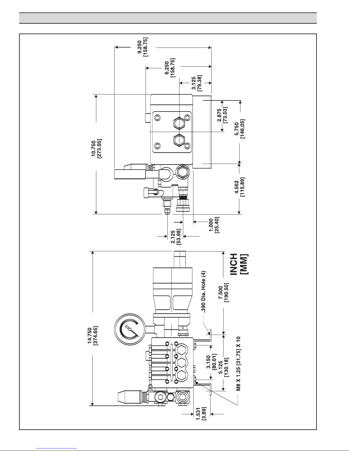
Mounting Dimensions
Figure 28
Mounting Dimensions
12
Page 13
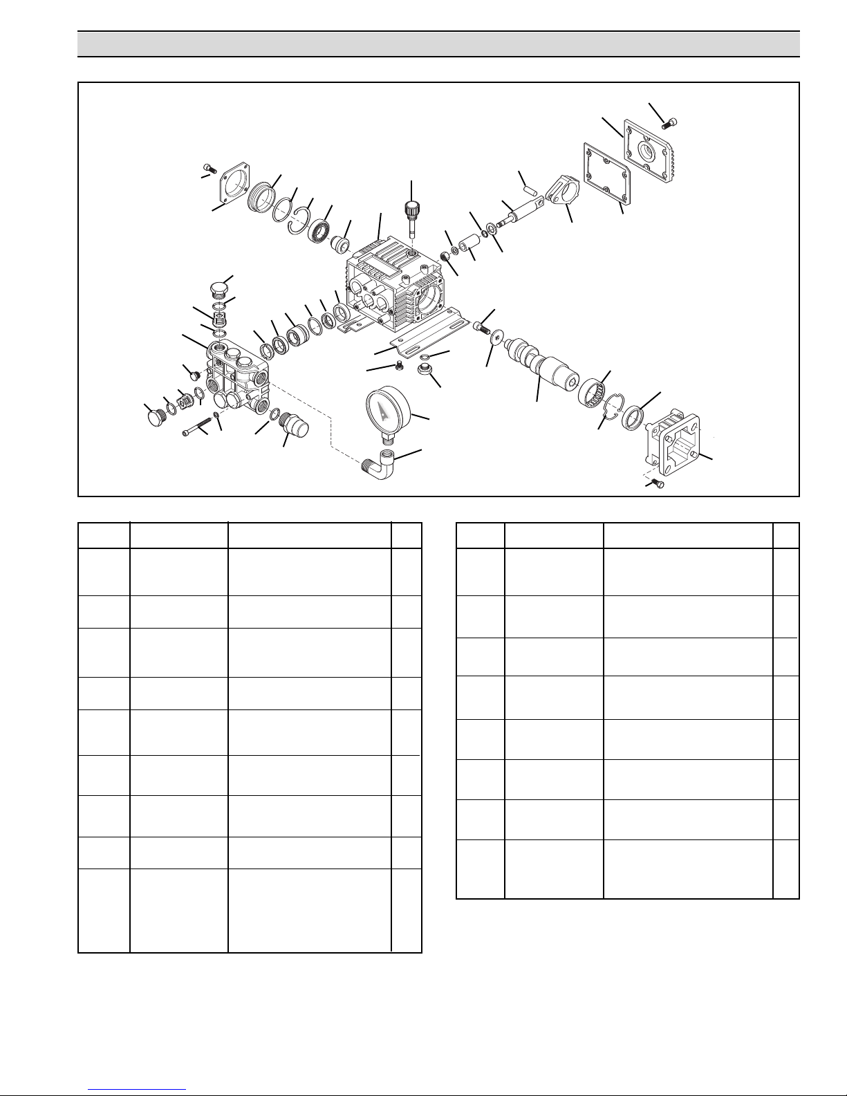
Models 1802C, 1803C, 1804C, 1805C, 1806C and 1807C Parts List
31
32
26
30
29
28
80
79
81
82
7
9
10
40
2
9
8
7
10
85
1
17
18
19
20
21
16
42
13
14
15
48
47
8
12
11
41
22
23
27
25
24
38
39
87
86
Figure 29
Models 1802C, 1803C, 1804C, 1805C, 1806C and 1807C Exploded View
Ref. No. Part No. Description Qty.
1 9910-680570 Socket Head Cap Screw 6
2 9910-620301 Plug 1
7 9910-1260162 Plug 6
1
8
9
10
11
12
13
14
15
16
17 9910-1320320 Plug 1
18 9910-1320360 O-ring 1
19
20 9910-1320370 Bearing 1
21 9910-1320330 Bushing 1
22 9910-1320010 Pump Housing 1
23 9910-880130 Oil Plug 1
24
25
26
27
28
29
30 9910-1260080 Piston Pin 3
9910-960160 O-ring 6
1
1
4
4
4
4
3
2
2
2
2
2
3400-0133 Valve 6
9910-880830 O-ring 6
1830-0138 Support Ring 3
9910-1260220 Gasket 3
1830-0139
9910-1260420
9910-1260450 Gasket 3
9910-1260460
9910-1260790 Retaining Ring (Internal) 1
9910-1260110 Nut 3
9910-1260100 Washer 3
3500-0061 Piston 3
9910-480480 O-ring 3
9910-1260091 Spacer 3
9910-1260070
Piston Guide
O-ring 3
Seal
Guiding Piston
3
3
3
Ref. No. Part No. Description Qty.
31 9910-1260760 Socket Head Cap Screw 6
32 9910-1269101 Complete Cover 1
36 9910-1260060 Connecting Rod
36 9910-1320140 Connecting Rod (Bronze) 1806C/1807C 1
3
37
38 9910-740290 O-ring 2
39 9910-1980740 Plug 2
40 0203-2250B Pump Head 1
41 9910-180101 O-ring 1
42 3312-0004 Thermal Relief Valve 1
47 9910-1260470 Screw 4
48 9910-1263890 Base 2
62
69 9910-1320050 Flange (Gas) 1
70 9910-1200430 Bolt 4
73 0551-2255 Hollow Shaft 5/8" Dia. 1
74 9910-1321190 Bearing 1
79
80 9910-780060 Socket Head Cap Screw 1
81
82 9910-1321420 Cover 1
84 9910-1321080 Snap Ring 1
85
86 2400-0048 Elbow 1
87 2640-0005 Pressure Gauge 1
9910-1260040 Gasket 1
3
9910-1381550
36
73
9910-480671
9910-780230
2220-0069
84
37
74
62
70
Seal
asher 1
W
Socket Head Cap Screw
asher
W
69
(Aluminum) 3
1
4
6
1
Denotes Valve Kit item. 9910-KIT1864
2
Denotes Piston Kit item. 9910-KIT2629
3
Denotes Oil Seal Kit item. 9910-KIT1860
4
Denotes Water Seal Kit item. 9910-KIT1874
13
Page 14
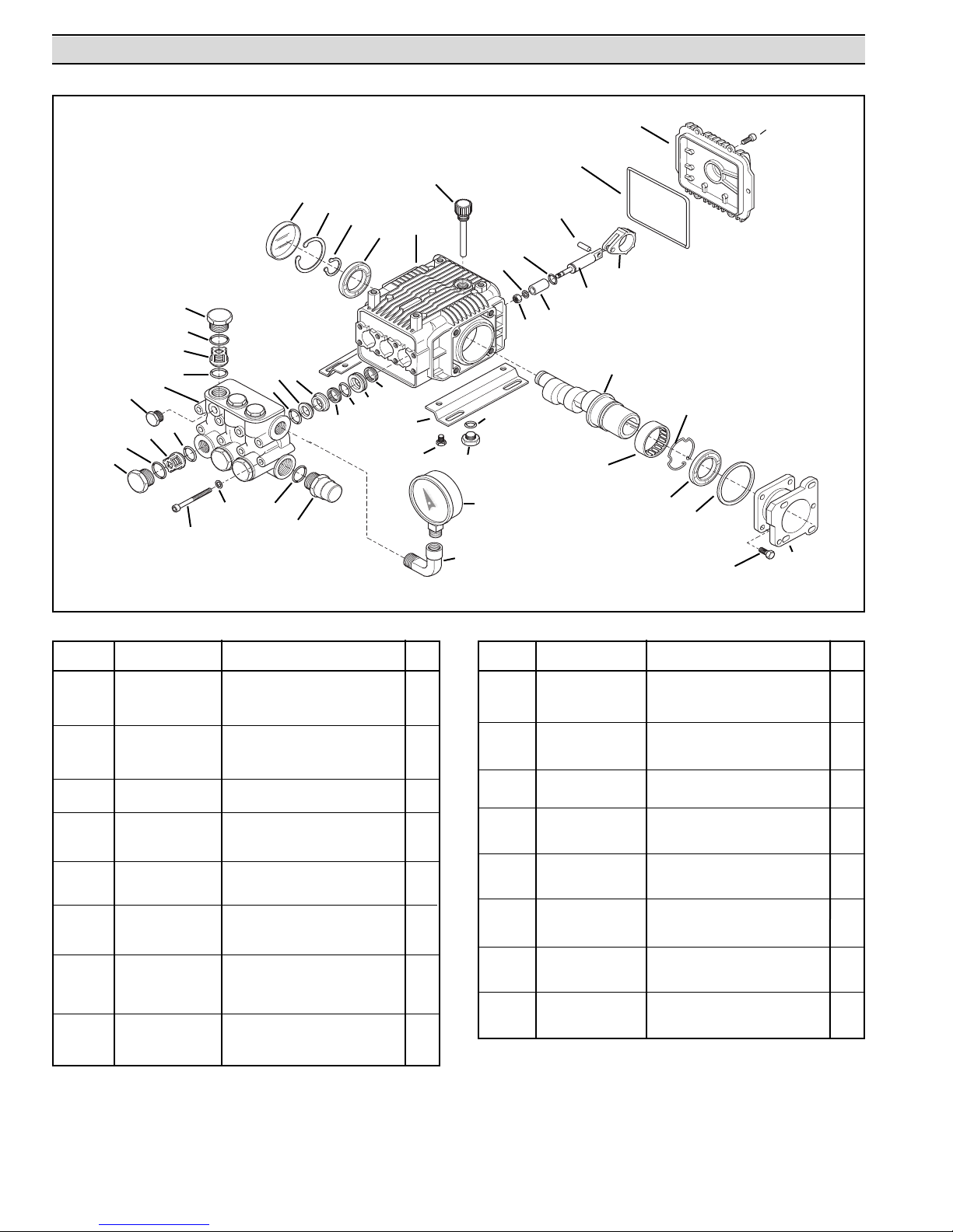
Models 1824C, 1825C, 1826C and 1827C Parts List
10
11
12
13
2
1
3
4
36
5
4
3
1
2
37
38
35
7
8
6
34
33
32
31
14
9
30
26
29
67
Figure 30
Models 1824C, 1825C, 1826C and 1827C Exploded View
28
68
27
24
21
25
15
23
16
20
40
63
19
18
42
41
62
66
17
64
Ref. No. Part No. Description Qty.
1 9910-960160 O-ring 6
2 9910-1260162 Plug 6
1
3
1
4
5 9910-620301 Plug 1
5
6
4
7
8
9 9910-1780010 Pump Body 1
3
10
1
1
12 9910-1780550 Retaining Ring (External) 1
13 9910-1780490 Bearing 1
14 9910-880130 Oil Cap 1
15
3
16
17 9910-1200430 Socket Head Cap Screw 6
18
19 9910-1780040 Connecting Rod 3
20
21
22 9910-1260091 Spacer Disc 3
2
23
24
1
Denotes Valve Kit item. 9910-KIT1864
2
Denotes Piston Kit item. 9910-KIT2746
3
Denotes Oil Seal Kit item. 9910-KIT2787
4
Denotes Water Seal Kit item. 9910-KIT2747
5
Denotes Support Ring Kit item. 9910-KIT2745
3400-0133 Valve 6
9910-880830 O-ring 6
9910-1780140 Support Ring 3
9910-1260220 Gasket 3
9910-1780110 Piston Guide 3
9910-1266740 Cap 1
9910-1260790
9910-1780050
9910-1780510
9910-1789010
9910-1780060 Guiding Piston 3
9910-480480
9910-1780080
9910-1260100
Retaining Ring (Internal)
Piston Pin
O-ring 1
Complete Cover
O-ring 3
Piston
Piston W
asher
Ref. No. Part No. Description Qty.
25 9910-1260110 Nut 3
26 9910-1380141 Base 2
27 9910-740290 O-ring 2
28 9910-1980740 Plug 2
29 9910-1260470 Screw 4
3
30
31
32
33
34 3312-0004 Thermal Relief Valve 1
1
3
1
3
3
35 9910-180101 O-ring 1
36
37 9910-1381550 Washer 8
38 9910-1322730 Socket Head Cap Screw 8
40
41
42
62 9910-1780430 Bushing 1
63
64 9910-1780980 Gas Engine Flange 1
66
67
68 2640-0005 Pressure Gauge 1
9910-1260460 Seal 3
9910-1780120
4
9910-770260 O-ring 3
4
9910-1260450
9910-1780020
9910-1321190 Bearing 1
9910-1321080
3
9910-480671 Seal 1
9910-1780990
9910-180432 Bolt 4
2400-0048
Rear Piston Guide
Gasket
Head
Snap Ring 1
Hollow Shaft
Elbow
3
3
1
1
1
14
Page 15
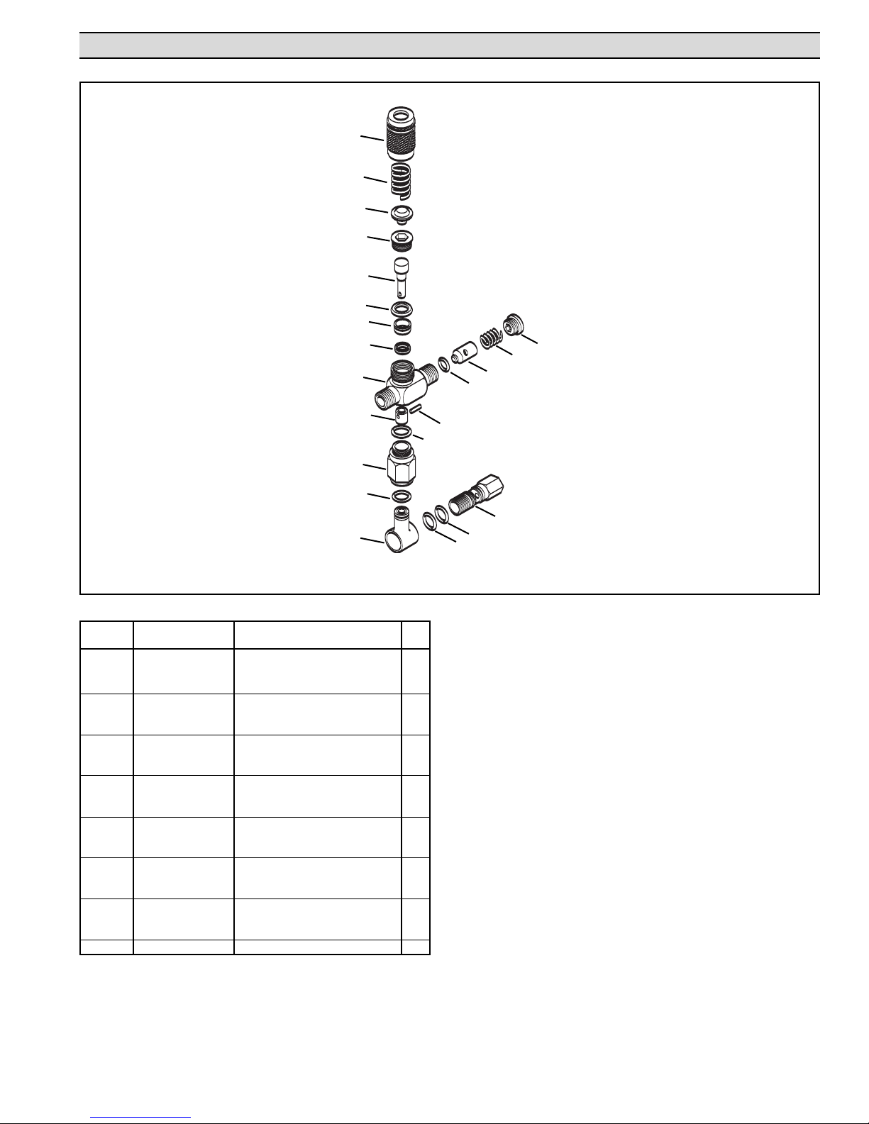
Unloader/Bypass Valve Model 3390-0086 (Models 1802C/1803C)
1
2
3
4
5
6
7
8
9
16
15
10
14
22
11
18
17
12
13
Figure 31
Injector/Unloader Seat and Seal Kit Items
Ref. No. Part No. Description Qty.
1 3220-0039 Pressure Adjustment Nut 1
2 1900-0116 Main Spring 1
3 1900-0101 Spring Button 1
4 2404-0151 Plunger Retainer 1
5 2404-0016 Plunger 1
1
6
7 1400-0020 Sleeve 1
1
8
9 0117-3390 Valve Body 1
10 3260-0037 Bypass Poppet 1
11 1830-0140 Bypass Seal/Outlet 1
12 1720-0004 O-ring 1
13 2404-0164 Bypass Adapter 1
14 1600-0041 Poppet Pin 1
1
15
16 3260-0048 Check Valve Poppet 1
17
1900-0123
18 1830-0115 Poppet Retainer 1
19 1720-0004 O-ring 1
20
21 2404-0164 Bypass Adapter 1
1
22
1
Denotes Repair Kit item. Repair Kit No. 3430-0223
1720-0064 O-ring 1
Cup 1
Cup
O-ring 1
alve Spring
Check V
O-ring
21
20
19
1
1
1
15
Page 16
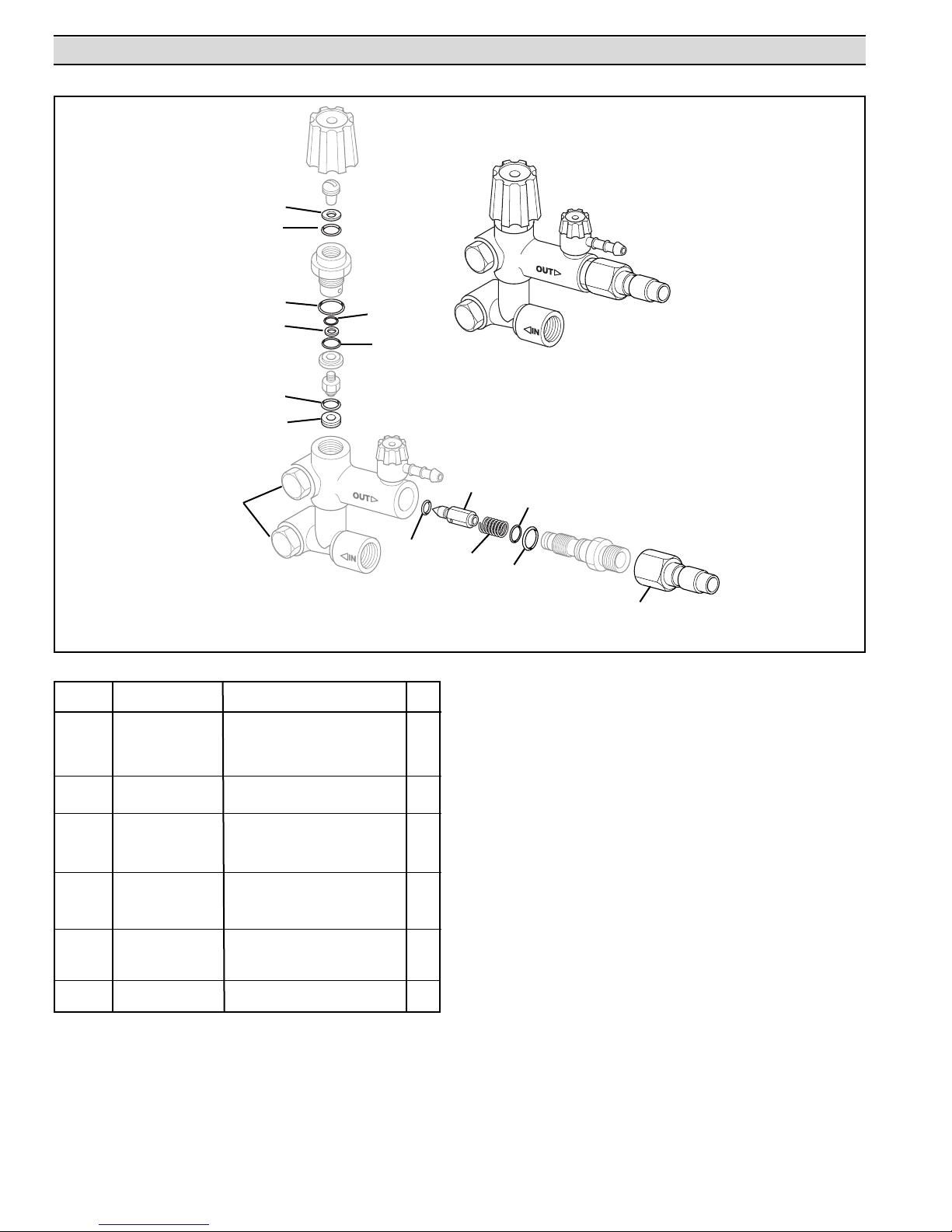
3390-0104/2B Unloader Assembly-Models 1804C/1805C, 1806C/1807C, 1824C/1825C, 1826C/1827C
1
2
3
5
7
8
15
4
6
9
Figure 32
Unloader Assembly Items
Ref. No. Part No. Description Qty.
1
1
2
3
4
5
6
7
8
9
10
11
12
13
14
15 3430-0483 Bolt Kit Assembly (NPT) 1
15 3430-0487 Bolt Kit Assembly (BSP) 1
Repair Kit Item W
1
Repair Kit Item O-ring 1
1
1
1
1
1
1
1
1
1
1
1
1720-0186 O-ring 1
Repair Kit Item O-ring 1
Repair Kit Item Washer 1
1720-0196 O-ring 1
1720-0163 O-ring 1
3210-0080
1720-0190 O-ring 1
3320-0035 Piston 1
1900-0161 Spring 1
Repair Kit Item O-ring 1
Repair Kit Item O-ring 1
9900-38FPB
Quick Disconnect (Male End)
asher 1
Valve Seat 1
1
10
12
11
13
14
1
Denotes Parts Kit items. Parts Kit No. 3430-0484
16
Page 17
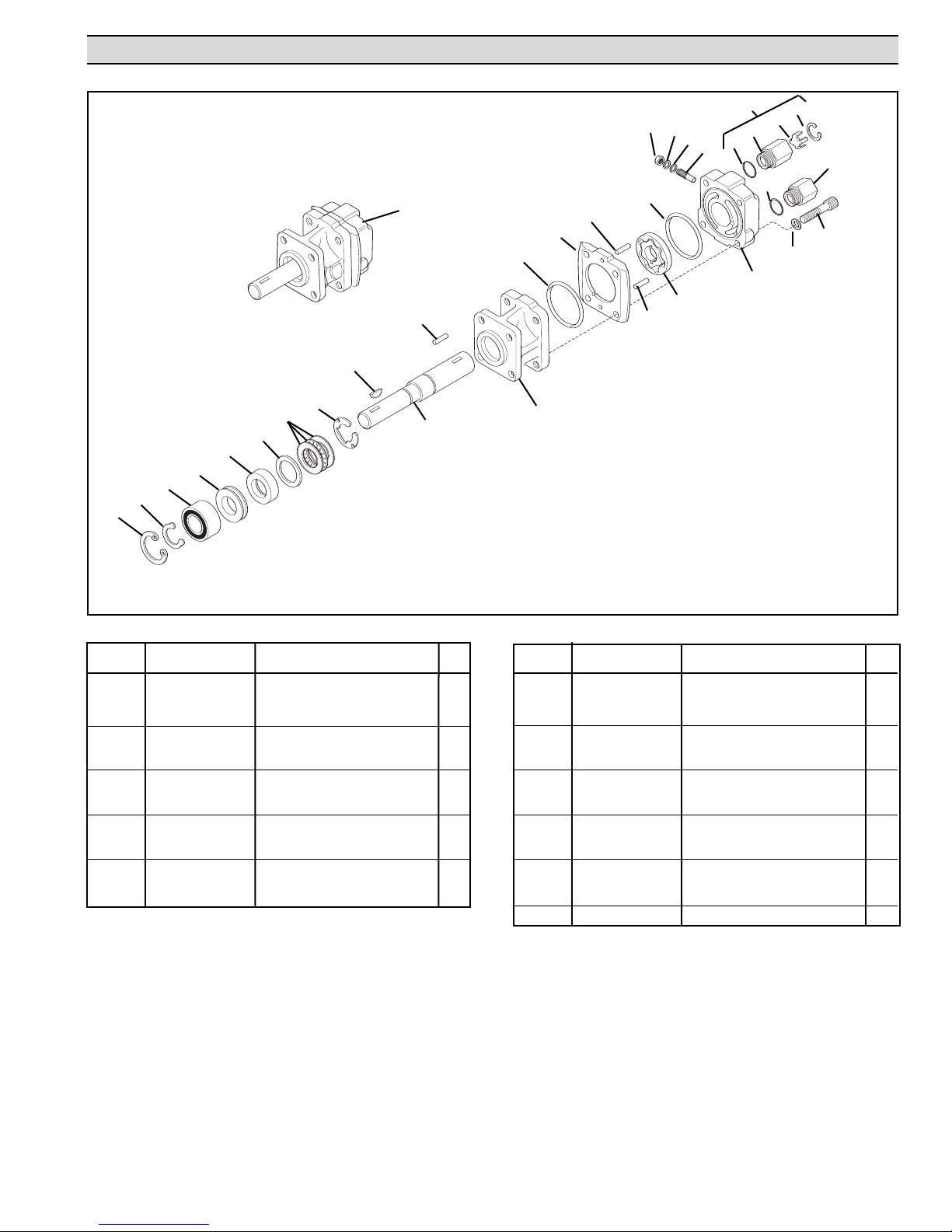
Model No. 2500-0015C Hydraulic Motor Parts List - Models 1802C/1803C, 1804C/1805C
22
21
20
19
29
25
26
27
28
30
25
31
16
14
13
13
24
23
18
17
11
15
10
8
7
6
9
2
1
5
4
3
2
1
Figure 33
Hydraulic Motor Exploded View 2500-0015C
Ref. No. Part No. Description Qty.
1 1820-0013 Retaining Ring (Internal) 1
2 1810-0014 Retaining Ring (External) 1
1
3
4 1410-0073 Spacer 1
1
5
6 1410-0074 Seal Spacer 1
7 2029-0014 Thrust Bearing Assembly 1
8
9
10 0610-0012 Key 1
11 1610-0031 Roll Pin (HM1C) 1
12 0152-2500C Motor Body & Main Bearing 1
13
14
15 1600-0044 Dowel Pin (HM1C) 1
1
Denotes Parts Kit item. Parts Kit No. 3430-0178
2000-0010 Ball Bearing 1
2104-0005
1810-0026
0512-2500
1
1720-0110 O-ring 1
0700-2500C1
Shaft Seal 1
Snap Ring
Shaft (HM1C)
Gerotor Housing (HM1C)
Ref. No. Part No. Description Qty.
16 1600-0047 Dowel Pin 1
17 3900-0022 Dowel Pin (HM1C) 1
18 0251-2500C2 Motor End Plate & Main Brg. 1
19 3220-0029 Bypass Adjusting Screw 1
1
20
1
21
22
1
1
23 2270-0039 Washer 4
24
1
25
1700-0047
2270-0027 Washer 1
2250-0038
2220-0021 Cap Screw 4
1720-0108
Gasket
Lock Nut
O-ring 2
1
1
26 3320-0016 Tank Port Adapter 1
27
3260-0039
Poppet
1
28 1820-0023 Retaining Ring (Internal) 1
1
29 3320-0015 Tank Check Valve Assy. 1
30
3360-0021
Pressure Port
Adapter 1
31 2500-0015C Complete Motor Assy. 1
17
Page 18
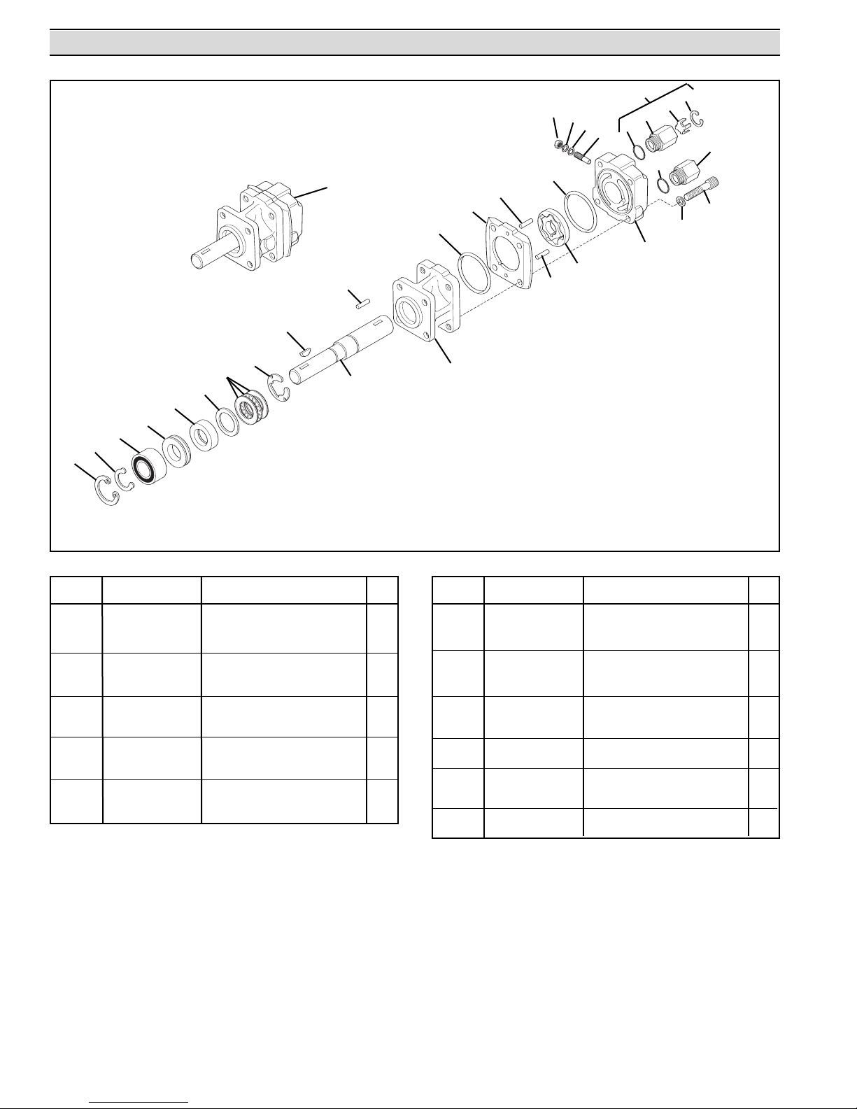
Model No. 2500-0020C Hydraulic Motor Parts List - M
odels 1806C/1807C, 1824C/1825C, 1826C/1827C
29
22
21
20
25
19
31
13
11
10
8
7
6
5
4
3
2
1
9
1
16
14
2
13
17
15
26
18
25
27
28
30
24
23
Figure 34
Hydraulic Motor Exploded View 2500-0020C
Ref. No. Part No. Description Qty.
1 1820-0013 Retaining Ring (Internal) 1
2 1810-0014 Retaining Ring (External) 1
1
3
4 1410-0073 Spacer 1
1
5
6 1410-0074 Seal Spacer 1
7 2029-0014 Thrust Bearing Assembly 1
8
9 0513-2500 Shaft 1
10 1610-0012 Key 1
1 1610-0055 Roll Pin 1
1
12 0152-2500C Motor Body & Main Bearing 1
1
13
14 0702-2500C1 Gerotor Housing (HM3C) 1
15 1600-0068 Dowel Pin 1
1
Denotes Parts Kit item. Parts Kit No. 3430-0178
2000-0010 Ball Bearing 1
2104-0005
1810-0026
10
1720-01
Shaft Seal 1
Snap Ring
O-ring 2
Ref. No. Part No. Description Qty.
16 1600-0052 Dowel Pin 1
17 3900-0024 Gerotor (HM3C) 1
18 0251-2500C2 Motor End Plate & Main Brg. 1
19 3220-0029 Bypass Adjusting Screw 1
1
20
1
21
1
22 2250-0038 Lock Nut 1
23
24 2220-0021 Cap Screw 4
1
25
26 3320-0016 Tank Port Adapter 1
27 3260-0039 Poppet 1
28
29 3320-0015 Tank Check Valve Assy. 1
30 3360-0021 Pressure Port Adapter 1
31 2500-0020C Complete Motor Assy. 1
1700-0047 Gasket 1
2270-0027 Washer 1
asher
2270-0039
1720-0108 O-ring 2
1820-0023
W
Retaining Ring (Internal) 1
4
18
Page 19
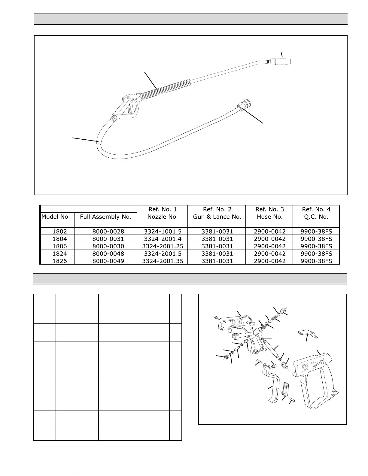
Gun, Lance, Nozzle and Hose Assembly Parts List
2
3
Figure 35
Gun, Lance, and Hose Replacement Components
1
4
Ref. No.
1 2800-0023 Case (Right and Left) 1
2
3 1610-0049 Pin 1
4 1610-0050 Trigger Pin 1
5
6 0101-3381B Body (3381-0018) 1
7 Repair Kit Item Plunger Sleeve 1
8 Repair Kit Item O-ring (Viton) 1
9 Repair Kit Item Plunger 1
10
11 Repair Kit Item Seal 1
12 Repair Kit Item Retainer 1
13
13
14 1720-0163 O-ring 1
15 Repair Kit Item Ball 1
16 Repair Kit Item Spring 1
17 Repair Kit Item O-ring 1
18
19 2270-0068 Seal (Washer) 2
20 2404-0223 Tube (Inlet) 1
21 2404-0224 Tube (Adapter) 1
22 2200-0038 Screw 7
Part No.
2825-0023
3210-0082
Repair Kit Item
3210-0081 Seat (3381-0018) 1
3210-0083
Repair Kit Item
Description Qty.
rigger
T
ear Pin 1
rigger W
T
O-ring (V
Seat (3381-0018 Std.)
iton)
Retainer
Repair Kit No. 3430-0398
Gun Parts List
22
1
12
1
1
1
Figure 36
Gun Replacement Components
10
13
15
17
18
16
14
19
20
19
5
2
2
21
3
2
1
1
6
8
7
9
1
1
4
19
Page 20

Limited Warranty on Hypro Pumps
Hypro warrants to the original purchaser of its products (the “Purchaser”) that such products will be free from defects in material and
workmanship under normal use for the period of one (1) year for all products except: oil crankcase plunger pumps will be free from
defects in material and workmanship under normal use for the period of five (5) years, and accessories will be free from defects in
aterial and workmanship under normal use for the period of ninety (90) days. In addition, Hypro warrants to the purchaser all forged
m
brass pump manifolds will be free from defects in material and workmanship under normal use and from damage resulting from
nvironmental conditions for the life of the pump.
e
“Normal use” does not include use in excess of recommended maximum speeds, pressures, vacuums and temperatures, or use
requiring handling of fluids not compatible with component materials, as noted in Hypro product catalogs, technical literature, and
nstructions. This warranty does not cover freight damage, freezing damage, normal wear and tear, or damage caused by
i
misapplication, fault, negligence, alterations, or repair that affects the performance or reliability of the product.
THIS WARRANTY IS EXCLUSIVE. HYPRO MAKES NO OTHER WARRANTY, EXPRESS OR IMPLIED, INCLUDING BUT NOT
LIMITED TO ANY WARRANTY OF MERCHANTABILITY OR FITNESS FOR A PARTICULAR PURPOSE.
Hypro’s obligation under this warranty is, at Hypro’s option, to either repair or replace the product upon return of the entire product to
the Hypro factory in accordance with the return procedures set forth below.
BREACH OF WARRANTY.
IN NO EVENT SHALL HYPRO BE LIABLE FOR ANY INCIDENTAL OR CONSEQUENTIAL DAMAGES OF ANY KIND,
WHETHER FOR BREACH OF ANY WARRANTY, FOR NEGLIGENCE, ON THE BASIS OF STRICT LIABILITY, OR OTHERWISE.
Return Procedures
All pumps or products must be flushed of any chemical (ref. OSHA Section 0910.1200 (d)(e)(f)(g)(h) and hazardous chemicals must
be labeled before being shipped* to Hypro for service or warranty consideration. Hypro reserves the right to request a Material Safety
Data sheet from the Purchaser for any pump or product Hypro deems necessary. Hypro reserves the right to “disposition as scrap”
pumps or products returned which contain unknown substances, or to charge for any and all costs incurred for chemical testing and
proper disposal of components containing unknown substances. Hypro requests this in order to protect the environment and
personnel from the hazards of handling unknown substances.
THIS IS THE EXCLUSIVE REMEDY FOR ANY
For technical or application assistance, call the Hypro Technical/Application number: 800-445-8360.
To obtain service or warranty assistance, call the Hypro Service and Warranty number: 800-468-3428; or call the Hypro Service and
Warranty FAX: (651) 766-6618.
Be prepared to give Hypro full details of the problem, including the following information:
1. Model number and the date and from whom you purchased your pump.
2. A brief description of the pump problem, including the following:
• Liquid pumped. State the pH and any non-soluble • Drive type (gas engine/electric motor; direct/belt drive;
materials, and give the generic or trade name. tractor PTO) and rpm of pump.
• Temperature of the liquid and ambient environment. • Viscosity (of oil, or other than water weight liquid).
• Suction lift or vacuum (measured at the pump). • Elevation from the pump to the discharge point.
• Discharge pressure. • Size and material of suction and discharge line.
• Size, type, and mesh of the suction strainer. • Type of spray gun, orifice size, unloader/relief valve.
Hypro may request additional information, and may require a sketch to illustrate the problem. Contact the factory to receive a return
material authorization before sending the product. All pumps returned for warranty work should be sent shipping charges prepaid to:
HYPRO
Attention: Service Department
375 Fifth Avenue NW
New Brighton, Minnesota 55112
*Carriers, including U.S.P.S., airlines, UPS, ground freight, etc., require specific identification of any hazardous materials being
shipped. Failure to do so may result in a substantial fine and/or prison term. Check with your shipping company for specific
instructions.
Hypro 2008
Printed in the USA
 Loading...