

Hypro 1500 SERIES, 9263C-C-SP, 9500P SERIES, 9203C-SP, 9203C-R-SP Installation, Operation, Repair Instructions
...Page 1
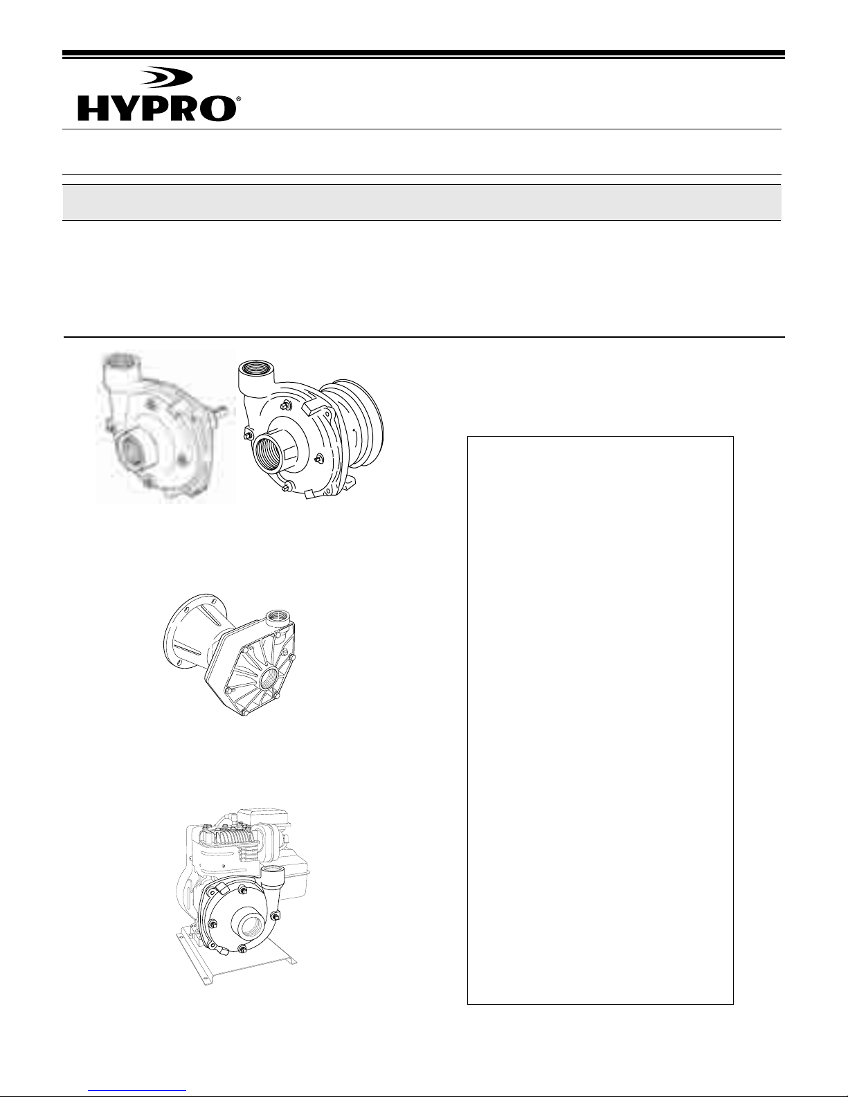
Series 9200, 9500 and 1536 through 1551
Direct and Gas Engine-Driven Centrifugal Pumps
Installation, Operation, Repair Instructions
Description
Form 300AG
2-04
Hypro Centrifugal Pumps handle big, high-capacity
farm spraying jobs with ease. Use them for spraying
liquid fertilizers and other chemicals, including wettable
powder slurries for weed control. Make short work of
other farm jobs - filling nurse tanks, watering seed
beds, and transferring liquids.
SERIES 9200
Cast Iron, Stainless Steel
Pedestal-Mount Centrifugal Pumps
Available in a variety of models, including lightweight
polypropylene (pump portion only) pumps for resistance
to corrosive liquids such as acid-based fertilizers.
This form replaces Form 300C. For individual parts
breakdowns, product outlines and performance
specifications, visit www.hypropumps.com.
See chart below for new form numbers.
Pump/Model New Form
Number Number
All 9202 Series.......................300AG-1
All 9203 Series.......................300AG-2
9203C-SP
and 9263C-C-SP....................300AG-3
9203C-R-SP,
and 9263C-CR-SP .................300AG-4
SERIES 9500P
Polypropylene
Flange-Mount Centrifugal Pumps
SERIES 1500
Close-Coupled, Gas Engine-Driven
Centrifugal Pumps
9203P-S,
and 9253P-C..........................300AG-5
9204C ....................................300AG-6
9205C ....................................300AG-7
9205C-SP
and 9205C-BSP .....................300AG-8
9206C and 9206S..................300AG-9
9510P and 9513P ................300AG-10
1536, 1537, 1538,
1539 and 1540.....................300AG-11
1536-SP, 1537-SP,
1539-SP and 1540-SP.........300AG-12
1550, 1550-SP,
1550-BSP, 1551,
1551-SP and 1551-BSP ......300AG-13
Page 2
- 2 -- 2 -
Safety Information
1. WARNING: Do Not Pump Flammable or
Explosive Fluids Such as Gasoline, Fuel Oil,
Kerosene, etc. Do Not Use in Explosive
Atmospheres. The Pump Should be Used Only
with Liquids that are Compatible with the Pump
Component Materials. Failure to Follow this
Warning Can Result in Personal Injury and/or
Property Damage and Will Void the Product
Warranty.
2. Be sure all exposed moving parts such as PTO
shafts and adapters are properly shielded or
guarded and that all coupling devices are securely
attached before applying power.
3. Pumps mounted directly onto PTO shaft or other
power shaft must be prevented from rotating with the
power shaft. Pump must float freely on the power
shaft and must not be tied rigidly to equipment on
which it is mounted.
4. DO NOT EXCEED recommended speed, pressure
and temperature (140˚ F) for pump and equipment
being used.
5. BEFORE SERVICING, disconnect all power, make
sure all pressure in the system is relieved, drain all
liquids from the system and flush. On gas enginedriven models, remove the spark plug wire from the
spark plug before servicing the pump or engine.
6. Secure the discharge lines before starting the pump.
An unsecured line may whip, causing personal injury
and/or property damage.
7. Check hose for weak or worn condition before each
use. Make certain that all connections are tight and
secure.
8. Periodically inspect the pump and the system
components. Perform routine maintenance as
required (see Maintenance section).
9. Protect pump from freezing conditions by draining
liquid and pumping rust inhibiting antifreeze solution
through the system, coating the pump interior.
10. Do not operate a gasoline engine in an enclosed
area. Be sure the area is well ventilated.
WARNING: Gasoline is a Highly Combustible Fuel.
The Improper Use, Handling, or Storage of Gasoline
Can be Dangerous. Never Touch or Fill a Hot Engine.
11. Use only pipe, hose and fittings rated for the
maximum psi rating of the pump.
12. Do not use these pumps for pumping water or other
liquids for human or animal consumption.
1. Always drain and flush pump before servicing or
disassembling for any reason (see instructions).
2. Always drain and flush pumps prior to returning unit
for repair.
3. Never store pumps containing hazardous chemicals.
4. Before returning pump for service/repair, drain out all
liquids and flush unit with neutralizing liquid. Then,
drain the pump. Attach tag or include written notice
certifying that this has been done. Please note that it
is illegal to ship or transport any hazardous
chemicals without United States Environmental
Protection Agency Licensing.
This manual will cover the installation of the basic drive configurations available for Hypro direct-drive centrifugal
pumps. Consult the manufacturer of your tractor, motor or engine for additional information. Read all instructions and
general safety information before attempting to install or operate the pump.
Hazardous Substance Alert
Drive Source Installation
Series 9200 Pedestal-Mounted
Centrifugal Pumps
Mounting Belts and Pulleys
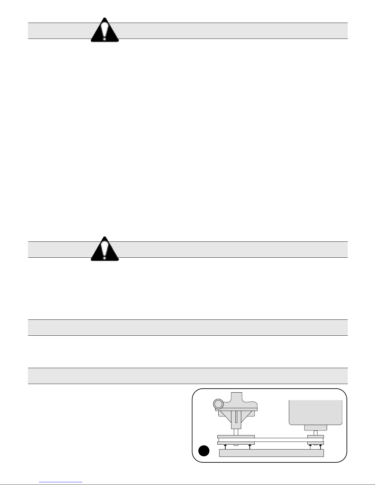
Mount pulleys as close to pump and motor engine shaft
bearings as possible. Check alignment with a straight
edge as shown in Fig. 1. Make sure that belt has proper
tension. (Too much tension will cause bearing wear; too
little will cause slippage.) See Fig. 2. Check with belt and
pulley sources for specific recommendation.
Belt/Pulley Drive Installation
Straight Edge
Electric Motor
or
Gas Engine
1
Page 3
- 3 -
Belt/Pulley Drive Installation (cont'd)
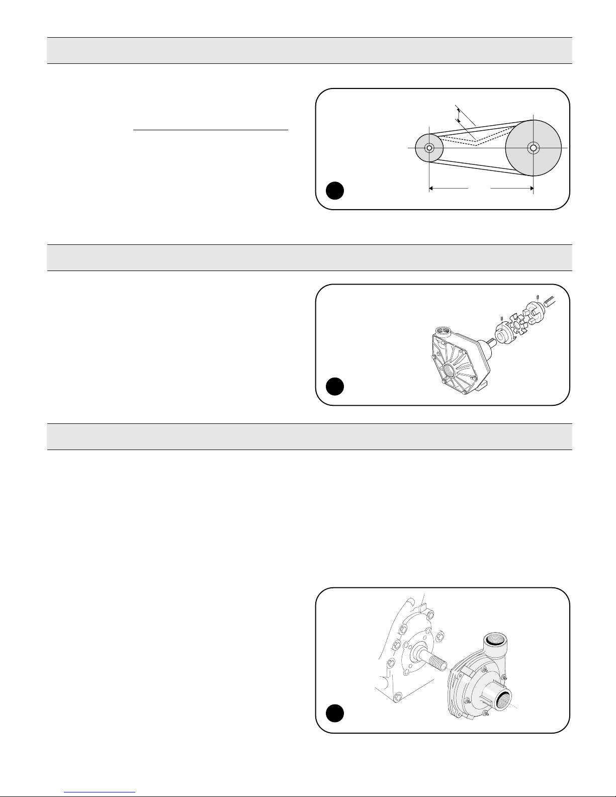
To figure proper diameter of pump pulley, multiply
motor/engine rpm by diameter of the motor/engine pulley
and divide that figure by desired pump speed.
Pump = Motor RPM x Motor Pulley Size
Pulley Size Desired Pump Speed
Refer to pump performance charts to determine desired
speed to obtain desired maximum flow.
IMPORTANT: Note that shaft rotation is counterclockwise as viewed from the shaft - opposite from
most standard centrifugals. Be sure to drive pump
in proper direction.
Series 9200 and 9500P Pedestal-Mounted
Centrifugal Pumps
To install couplings, slide coupling ends onto motor or
engine and pump shafts as far as possible. Mount
engine/motor and pump on base. Shim up pump or
power to align shafts. Leave enough room between shaft
ends to install center disc. When aligned, slide ends over
disc. Select couplings rated twice required horsepower
when using motor; three times when using gas engine.
Refer to your pump parts breakdown.
1. Lubricate the seal cavity in the flange with WD-40,
LPS or equivalent.
Be extremely careful with the new seal. Take
special care not to scratch the lapped sealing
faces of the rotary seal and stationary seat.
2. Install the stationary portion of the mechanical seal
by pushing it into the bore of the flange with the
ceramic side out.
Important: Make sure the seal “cavity” is clean
and lubricated. Never run the sealing faces dry.
3. To seat the seal in the seal cavity, use a piece of
3/4" PVC pipe (1" for 1551) 4" to 6" in length. Press
seal in firmly and squarely.
4. Install slinger ring onto gas engine shaft.
5. Install flange onto the gas engine. Make sure the
flange bore fits into the bore on the engine.
See Fig. 4.
6. Insert four bolts and four seals (four bolts only for
1551) through the flange and into the gas engine.
Tighten to 80-100 inch pounds of torque.
7. To install the rotary portion of the mechanical seal,
place it over the shaft with the carbon side facing in,
and press until it bottoms out against the stationary
seal portion.
Important: Use care in installing the seal on the
shaft. The seal can be damaged by threads on
the engine shaft.
8. Install the gasket over the shaft against the rotary
portion of the seal.
9. Install the impeller onto the shaft, and hand tighten
until it is secure.
10. Install the o-ring on the mounting flange.
11. Place the pump casing on the mounting flange;
insert the bolts and tighten evenly.
Direct Drive - Flexible Coupling Installation
Direct Drive Gas Engine Installation for Models 1538 and 1551
d
L
2
Push the belt midway
between the pulleys,
check the deflection
(d) and adjust:
d = 0.016 X L
3
NOTE: Direction
of shaft rotation, as
viewed from the shaft
side is counterclockwise
for Series 9200 and
clockwise for 9500P.
9200P is shown.
4
Page 4
- 4 -
Direct Drive - Flange Mount Installation
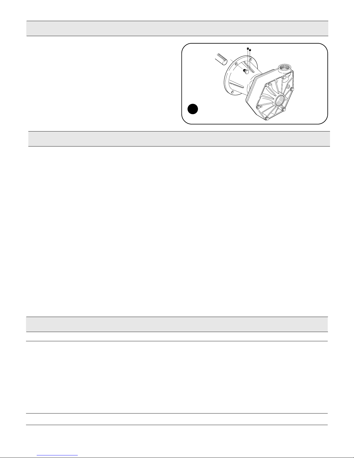
GAS ENGINE MOUNT — Models 9510P & 9513P
9510P fits most 8 hp gas engines with flange mount
and 1" shafts; 9513P fits most 5 hp gas engines with
flange mount and 3/4" shaft.
To install pump onto gas engine, first apply anti-seize
compound to gas engine shaft and to inside of pump
hollow shaft. Insert key into engine shaft. Next, slide
pump onto engine shaft and secure with four hex head
bolts. NOTE: Do not force pump onto shaft. Tighten set
screws on pump shaft through slots in flange. Check to
make sure pump rotates freely by slowly turning over the
gas engine.
Operation and Maintenance
IMPORTANT: ENGAGE PTO CLUTCH SLOWLY AND
SMOOTHLY. AVOID SUDDEN STARTS AND FAST
CLUTCHING THAT CAN DAMAGE THE DRIVE
SECTION OF THE PUMPS.
Controlling the Flow
Two flow control valves are used - one in the agitation
line and one in the line leading to the boom or spray
gun. This permits controlling agitation flow independently
of nozzle flow.
To Adjust For Spraying
To adjust sprayer (regardless of power source - PTO,
belt or pulley), follow these steps:
1. Prime pump with all valves open.
2. Close control valve and agitation line valve; open
boom shut-off valve.
3. With pump running, open the control valve until
pressure gauge indicates desired spraying pressure.
4. Open the agitation line valve until sufficient agitation
is observed. Then, if spraying pressure drops, readjust
the control valve to restore desired pressure.
5. Make sure flow is uniform from all nozzles.
After spraying adjustments are made, it is only
necessary to close boom shut-off valve to discontinue
spraying. On belt-drive models, check belt tension daily
or before each use.
Flush Pump After Use
One of the most common causes for faulty pump
performance is “gumming” or corrosion inside the pump.
Flush the pump and entire system with a solution that
will chemically neutralize the liquid pumped. Mix
according to manufacturer’s directions. This will dissolve
most residue remaining in the pump, leaving the inside
of the pump clean for the next use.
To Prevent Corrosion
After cleaning the pump as directed above, flush it with a
permanent-type automobile antifreeze (Prestone, Zerex,
etc.) containing a rust inhibitor. Use a 50% solution - that
is, half antifreeze and half water, or fill pump with FLUID
FILM and then drain it. A protective coating of FLUID
FILM will remain on the inner pump surfaces. Save the
excess FLUID FILM for the next application. Plug the
ports to keep out air during storage. For short periods of
idleness, non-corrosive liquids may be left in the pump,
BUT AIR MUST BE KEPT OUT. Plug ports or seal port
connections.
5
Troubleshooting
System Probable Cause(s) Corrective Action(s)
Low Discharge Pump not primed . . . . . . .Remove topmost vent plug from face of pump and run pump to expel trapped air
(See Installation instructions). Recommend vent line be used (KIT#3430-0456).
Air leaks in suction line . . .Check and reseal inlet fittings.
Blocked or clogged
line strainer or impeller . . .Inspect strainer and impeller to clear any debris or obstruction.
Undersize suction line or
collapsed hose . . . . . . . . .Suction line should be the same diameter as inlet port of pump or larger.
Eye of impeller rubbing
on volute . . . . . . . . . . . . .Remove volute (front cover) and inspect the impeller. If wear detected, sand
the impeller eye O.D. with emery cloth.
Liquid leaking Worn seal . . . . . . . . . . . . .Replace seal.
out weep port
Page 5
- 5 -
Always flush pump with water, or neutralizing agent,
before servicing.
Pump Housing Disassembly (All Models)
In most cases, seal replacement requires disassembly of only
the pump half of the unit.
NOTE: Instructions following in italics describe procedures for
the polypropylene centrifugal pumps, when different than the
cast iron pumps.
1. Remove the four casing cap screws with 9/16"
box end wrench. Tap pump casing on discharge port with
rubber hammer, if necessary, to break loose from mounting
flange. Check inside of pump casing including suction port.
If badly eroded [or damaged], pump casing should be
replaced. Remove o-ring and discard. o-ring should always
be replaced. [Using a 1/2" wrench, remove the six bolts from
the front. Also remove the 5/16" screw from the rear near the
outlet port.]
2. To remove the impeller nut, clamp the flange in a vise and
insert a large screwdriver or file (at least 10" long) into
impeller vanes to prevent impeller from turning when
loosening nut. Use a socket wrench (3/4" for Series 9000C
or 5/8" for Series 9200C and 9400C) to remove the impeller
nut by turning it counterclockwise (Fig. A). [Use 7/8" deep
socket wrench to remove plastic seal nut, then 9/16" deep
socket to remove metal jam nut, rubber gasket and washer.]
3. Once the nut [and washer] is removed, place a screwdriver
on each side (Fig. B) behind the impeller and pry away from
the mounting flange. Remove woodruff key from the shaft
(for Series 9000 only). Remove o-ring from the mounting
flange. NOTE: Fig. B shows 9000C gear flange. The same
general procedure applies for the other pumps.
Pump Seal Removal
1. Lightly lubricate shaft for easier removal of seal. Using two
screwdrivers positioned opposite each other, pry the rotary
portion of the seal from the shaft (Fig. C).
2. [Remove plastic back cover flange. Knock seal out from
back with a hammer and screwdriver.]
3. Remove stationary seat and boot by prying out with two
small screwdrivers in manner similar to impeller removal.
(Caution: The seal will be damaged by removal in this
manner. A new seal and rubber gasket MUST be used
when pump is reassembled.)
Clean-Up Of Pump Housing
1. Using the circular bottle-type wire brush with air or hand
drill, clean the discharge port, suction port and the sealing
areas of the o-ring on the pump casing and mounting
flange. [The last step should not be performed on the
polypropylene models.]
2. After wire brush cleaning, it is recommended that the pump
casing and mounting flange be further cleaned in a solvent
tank to remove rust and corrosion particles.
Pump Shaft and Bearing Assembly Removal and
Replacement
1. While the pump is disassembled (see the Pump Housing
Disassembly section), the driven pulley on the pump shaft
must be removed. Remove the large retainer ring in pump
bearing bore on the pulley side of housing. Press out the
shaft and bearing assembly from the pump side using an
arbor press.
2. Bearings must be pressed off each end of shaft and
replaced in the same manner. NOTE: Shaft diameter
between bearings is larger.
3. For reassembly, reverse the order of instructions.
Seal Replacement/Pump Housing Reassembly
NOTE: Reassemble if drive end is not to be repaired.
Be extremely careful with the new seal. Take special care not
to scratch the lapped sealing faces of the rotary washer and
stationary seat.
1. Lubricate seal cavity in mounting flange with WD-40, LPS
or equivalent.
2. Install the stationary portion of the mechanical seal by
sliding over the shaft with the ceramic side out.
IMPORTANT: Make sure the seal cavity is clean and
lubricated. Never run the sealing faces dry.
3. To seat the seal in the seal cavity, use a piece of 3/4" PVC
pipe 4" to 6" in length. Press it in firmly and squarely.
4. To install the rotary portion of the mechanical seal, place it
over the shaft with the carbon side facing in, and press until
it bottoms out against the stationary portion (Fig. D).
5. Insert key into shaft key slot. Place impeller on shaft. Put
[washer, jam nut and gasket] impeller nut on shaft end, and
using a large screwdriver or file in the impeller vanes for
support, tighten impeller nut securely.
6. Install o-ring on mounting flange. Replace o-ring if worn or
damaged.
7. Place pump casing on mounting flange, insert and tighten
bolts evenly.
Repair Instructions
Recommended repair tools for
use with these instructions:
C DA B
Page 6
- 6 -
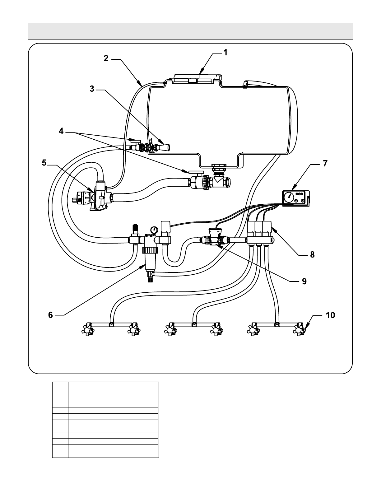
Plumbing Installation
Centrifugal Plumbing Hook-up
REF. DESCRIPTION
NO.
1 Tank Lid
2 Vent Line #3430-0456
3 Jet Agitator
4 Shut-off Ball Valves
5 Centrifugal Pump
6 Centrifugal Pump Control
7 Spray Control Console
8 Manifold Boom Valve
9 Electromagnetic Flowmeter
10 Compact Jet Turret Nozzle Body
Page 7
- 7 -
Plumbing Installation
Pump Installation:
The following are recommendations to achieve the
optimal performance out of your centrifugal pump and
your spraying system.
Pump Inlet Line
To achieve full capacity from the pump, the inlet line
should be at least the same size as the inlet port on the
pump. Reducing this line size will restrict the capabilities
of the pump. The line must also be free of air leaks.
Check all fittings and connections in the suction line for
tightness. The introduction of air may affect the priming
and pumping capabilities of the pump. Use good quality
suction hose that will not be collapsed by suction.
For non Self-Priming models, the centrifugal pump
should be mounted below the liquid level and as near to
the liquid source as possible to allow for the shortest
suction line practical. To achieve optimal performance,
the suction line should slope down into the pump. Avoid
rises and humps that could trap air in the line to the
pump. The suction line and pump should be filled with
liquid prior to starting the pump and all discharge lines
should be open.
Priming:
IMPORTANT: PUMP MUST NOT BE RUN DRY.
In addition to the proper suction plumbing, a vent line
should be installed to assist in priming. Use a Hypro
Vent Line Kit 3430-0456. The vent line will help to
prevent air locks and allows air to bleed off to the tank.
This helps ensure proper priming and helps to prevent
dry-run damage to the mechanical seal during priming.
The vent line should be installed in the top port of the
pump casing and the line routed sloping upward to the
tank, where it should be mounted above the liquid line.
Pump Outlet Line
The recommended orientation for the outlet port is
pointing straight up. This allows liquid to stay in the
pump while it is priming. The outlet line should be the
same size as the pressure port on the pump to give the
optimal flow. The line should have as few restrictions and
elbows as possible to optimize the pump performance
and reduce pressure drop from the pump to the spray
tips.
Centrifugal Pump Control
Hypro now offers many different components for
spraying systems. The Hypro centrifugal pump control
incorporates the electric flow control valve, a selfcleaning line strainer, a visual pressure gauge and
a manual agitation control valve.
Flow Control Valve
A high-flow electric proportional valve allows for
maximum flow control to the boom valves. It provides
smooth, rapid control that can be controlled from either
an electronic rate controller or switch box.
Strainers
The recommended placement of the strainer for a
centrifugal pump is in the pump outlet line. This will
eliminate any possible restriction that the strainer could
create if it were installed in the inlet line. Ensure that the
proper strainer size and screen mesh are used to limit
the pressure drop and achieve the best filtration. Line
strainers can also be installed in the tank fill line to filter
liquid as it is loaded into the tank as well as in the boom
lines to further filter the solution prior to the spray tips.
Tank baskets can also be used to filter material added
through the tank lid.
Agitation
The centrifugal pump control contains a manual agitation
control valve that can be adjusted to provide the right
amount of flow to the jet agitators in the tank to ensure
proper mixing within the tank.
Flowmeter
To eliminate the mechanical problems of a turbine
flowmeter, we recommend that an electromagnetic
flowmeter be used. These flowmeters have no moving
parts to wear out and will provide a more consistent
and accurate flow reading. They can be input into just
about any electronic rate controller or switch box.
Boom Section Valves
For rapid response and reliability, we recommend
electric plunger valves be used for boom control.
The valves should be sized accordingly to minimize
the pressure drop and maximize the flow rate.
The boom tubing or hose should be sized accordingly
to ensure that a pressure drop in the lines does not
occur, causing inconsistent pressures at the nozzles.
Nozzle Bodies
Nozzle bodies with shut-off check valves are
recommended to eliminate dripping from the spray tips
when the boom valves are shut down.
For further information
regarding Hypro products,
contact your local dealer
or Hypro directly at
www.hypropumps.com or by
calling 1-800-424-9776.
Page 8
Ref.
Qnty.
Ref.
Qnty.
No.
Req'd.
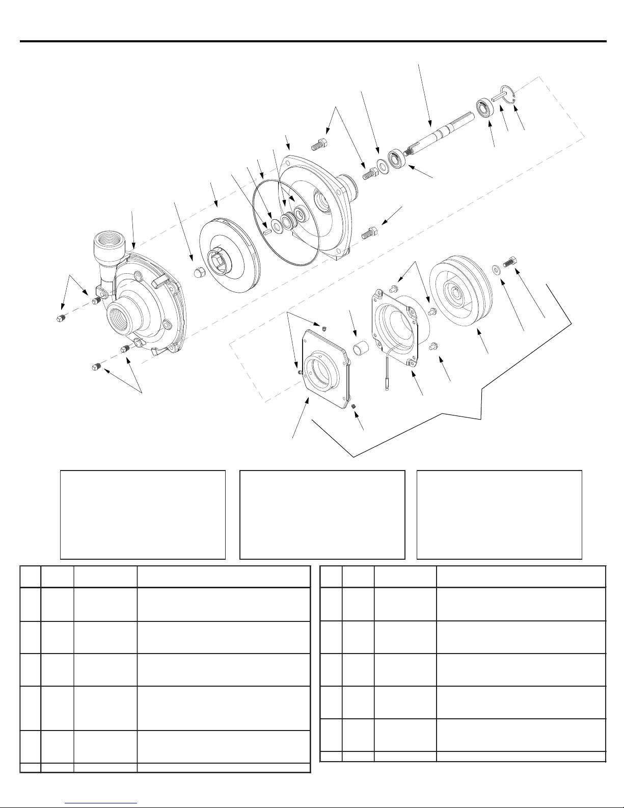
2 1 0150-9200C Pump Casing (Cast series) 13 1 1610-0015 Key (Cast series)
3 1 2253-0002 Impeller Nut 14 1 0505-9200 Pump Shaft
3 1 2253-0006 Impeller Nut ( Stainless series ) 15 1 1610-0004 Key
4 1 0401-9100P Impeller (Cast series ) ( Nylon ) 16 1 2210-0003 Bolt
4 1 0402-9100P 17 1 2270-0092 Retaining Washer
5 1 1720-0083 O-Ring 18 1 1410-0107 Spacer
6 1 3430-0589 Mech. Seal (Silicon Carbide) 21 1 1700-0100 Gasket (Cast series)
22 1 2526-0012 Clutch
9 1
0750-9200C3
9 1 0756-9200S 25 1 3430-0592 Clutch Kit
9202 Cast Iron and Stainless Steel Series
14
8
11
9
6
5
21
13
4
3
2
1
23
1
18
11
12
19
19
22
12
22
15
20
16
17
24
Seal Kit for Cast Iron series:
No. 3430-0332 consists of:
(1) Ref. 5 O-Ring
(1) Ref. 6 Mechanical seal
Seal Kit for Stainless series:
No. 3430-0589 consists of:
(1) Ref. 5 O-Ring
(1) Ref. 6 Mechanical seal
(1) Ref. 21 Gasket
Req'd. Part No. Description No.
1 4 2406-0007 Drain Plug (Cast series) 11 4 2210-0125 Bolt (Stainless series)
1 4 2406-0016 Drain Plug (316 Stainless series) 12 2 2000-0010 Ball Bearing
2 1 0156-9200S1 Pump Casing (Stainless w/plugs) 13 1 1610-0057 Key (Stainless series)
Impeller (Stainless series) ( Poly )
6 1 2120-0008 Mechanical Seal (Optional Buna-N) 19 4 N/A Bolt (part of Clutch Assy)
6 1 2120-0009 Mechanical Seal (Cast series) 20 1 1820-0013 Bearing Retainer
23
Note: When ordering parts, give
quantity, part number, description
and complete model number.
Reference numbers are used
ONLY to identify parts in the
drawing and NOT to be used
as order numbers.
Part No. Description
25
(SS series) Includes ref #5 O-Ring
8 1 1410-0056 Slinger Ring 23 3 2230-0001 Set Screw
Mounting Flange (Cast series ) 24 1 0753-9200C Mounting Bracket
Mounting Flange(Stainless series)
11 4 2210-0020 Bolt (Cast series)
Form 300AG-1 2-04
Page 9
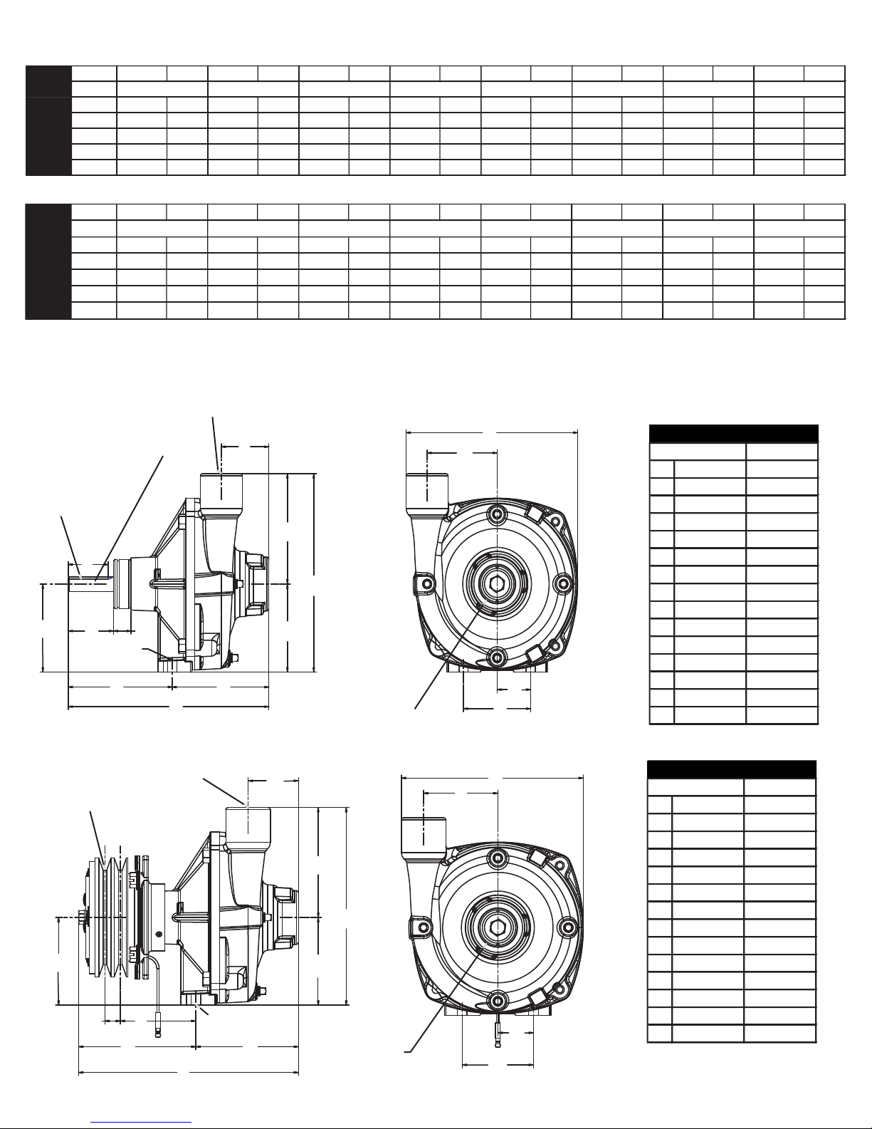
mm
A 2.13
B 1.78
C 3.69
D 2.02
E 0.78
F 4.64
G 9.01
H 4.37
I 3.69
J 8.25
K 4.56
L 7.78
M 3.06
N 3
O 1.5
Dimensions
Inches
mm
A 2.12
B 3.69
C 0.65
D 3.18
E 4.93
F 9.25
G 4.32
H 3.69
I 8.32
J 4.63
K 7.66
L 3.13
M 3
N 1.5
Dimensions
Inches
GPM at HP GPM at HP GPM at HP GPM at HP GPM at HP GPM at HP GPM at HP GPM at HP
RPM
2400 50 1.3 46 1.2
3600 67 3.7 66 3.7 62 3.5 34 2.6
4200 75 5.7 75 5.7 75 5.7 66 5.3 44 4.2
5000 88 0.3 88 9.3 88 9.3 88 9.3 77 8.6 60 7.5
6000 103 15.6 103 15.6 103 15.6 103 15.6 103 15.6 100 15.5 91 14.8 56 11.4
9202 and 9262
Series
10 PSI
20 PSI
40 PSI
60 PSI
80 PSI
100 PSI
120 PSI
140 PSI
LPM at HP LPM at HP LPM at HP LPM at HP LPM at HP LPM at HP LPM at HP LPM at HP
RPM
2400 189 1.3 174 1.2
3600 254 3.7 250 3.7 235 3.5 129 2.6
4200 284 5.7 284 5.7 284 5.7 250 5.3 167 4.2
5000 333 0.3 333 9.3 333 9.3 333 9.3 291 8.6 227 7.5
6000 390 15.6 390 15.6 390 15.6 390 15.6 390 15.6 379 15.5 344 14.8 212 11.4
5.5 BAR
6.9 BAR
8.3 BAR
9.7 BAR
0.7 BAR
1.4 BAR
2.8 BAR
4.1 BAR
9202 and 9262
Series
1"-11-1/2" NPT
OUTLET PORT
5/8" (15.88)
SHAFT
A
3/32" x 3/16"
KEYWAY
K
B
C D
.41 DIAM.
THRU HOLE (2)
E
F
H
I
G
5" DOUBLE
GROOVE A
SECTION
1"-11-1/2"
NPT OUTLET
PORT
A
PULLEY
B
C
D
E
.41 DIAM.
THRU HOLE (2)
G
F
J
1-1/4"-11-1/2"
NPT INLET
PORT
J
I
H
1-1/4"-11-1/2"
NPT INLET
PORT
M
L
9202
L
54
45
93.7
51.3
19.9
117.8
228.9
111.1
93.7
209.6
115.9
197.7
O
N
77.8
76.2
38.1
9262
K
53.8
93.7
16.5
80.7
125.3
235
109.7
93.7
211.2
117.5
194.5
79.4
76.2
N
38.1
M
Page 10
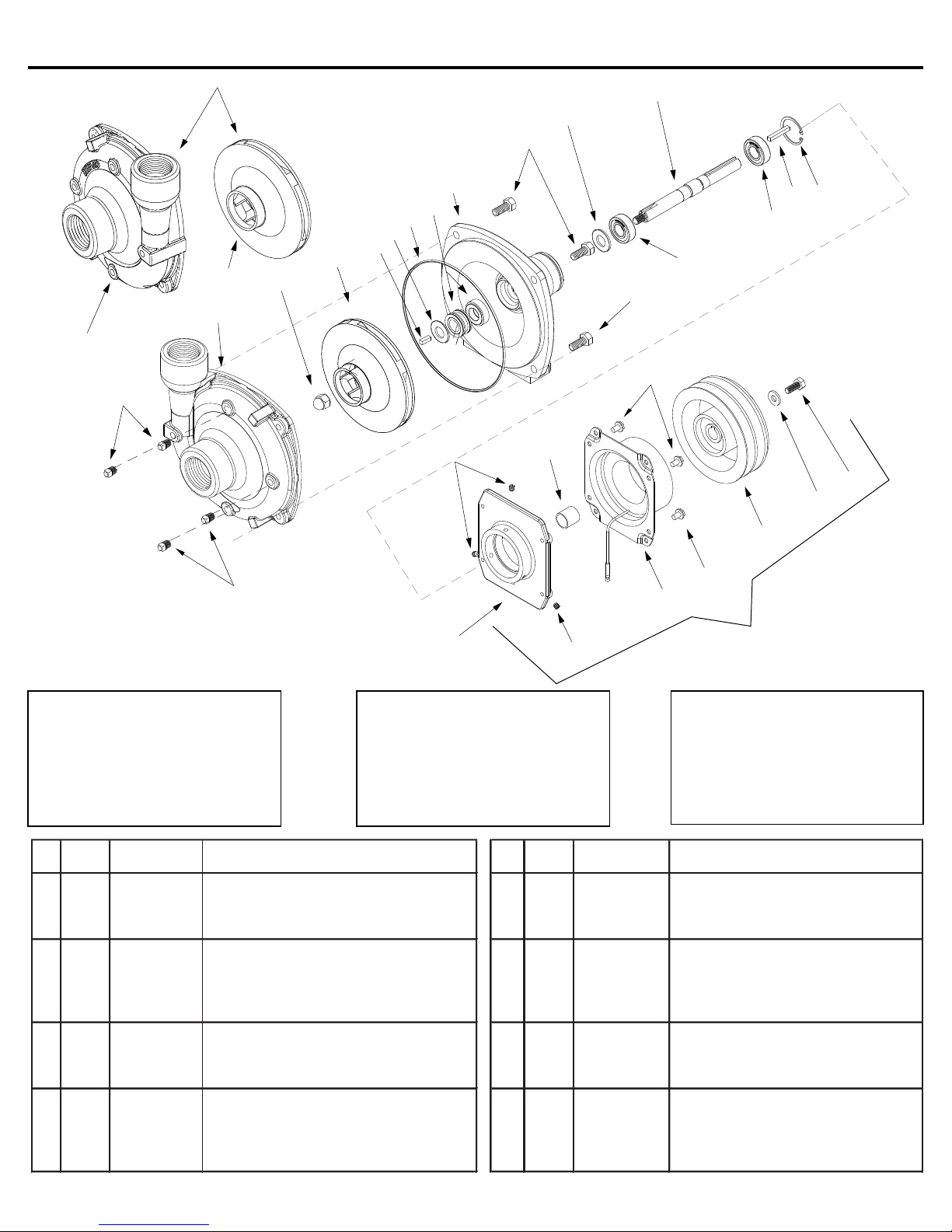
9203 Cast Iron and Stainless Steel Series
Qnty. Part Ref. Qnty. Part
No. Req'd. No. Description No. Req'd. No. Description
1 4 2406-0007 Drain Plug (Cast series) 8 1 3430-0589 Mech. Seal (Silicon Carbide)
1 4 2406-0016 Drain Plug (316 Stainless series ) (Stainless) Includes ref #5 O-Ring
2 1 0150-9000C Pump Casing (Cast series) 9 1 0750-9200C3 Mounting Flange (Cast series)
2 1 0150-9000S Pump Casing (Stainless series) 9 1 0756-9200S Mounting Flange (Stainless series)
2A 1 0152-9000C Pump Casing (Reverse)(Cast series) 10 4 2210-0020 Bolt (Cast series)
2A 1 0152-9000S Pump Casing (Reverse)(Stainless) 10 4 2210-0125 Bolt(Stainless series)
3 1 2253-0002 Impeller Nut (Cast series) 11 1 1410-0056 Slinger Ring
3 1 2253-0006 Impeller Nut (Stainless series) 12 2 2000-0010 Ball Bearing
4 1 0401-9100P Impeller ( Model 9203C ) ( Nylon ) 13 1 0505-9200 Pump Shaft
4 1 0402-9100P Impeller ( Model 9203S ) ( Poly ) 14 1 1610-0014 Key
4A 1 0404-9100P Impeller (Reverse)(Cast series) 15 1 1820-0013 Bearing Retainer
4A 1 0403-9100P Impeller (Reverse)(Stainless series) 16 1 2210-0003 Bolt
5 1 1610-0015 Key (Cast series) 17 1 2270-0092 Retaining Washer
5 1 1610-0057 Key (Stainless series) 18 1 1410-0107 Spacer
6 1 1700-0100 Gasket (Cast series) 19 4 N/A Bolt (part of clutch assy)
7 1 1720-0083 O-Ring 20 1 2526-0012 Clutch
8 1 2120-0008 Mechanical Seal (Optional Buna-N) 21 3 2230-0001 Setscrew
8 1 2120-0009 Mechanical Seal (Cast series) 22 1 3430-0592 Clutch Kit
2A
REVERSE ROTATION
4A
2
1
13
11
10
9
8
7
6
5
4
3
23
18
10
12
19
12
20
14
15
16
17
19
1
24
Seal Kit for Cast
Stainless
Series:
No. 3430-0589 consists of:
(1) Ref. 7 O-Ring
(1) Ref. 8 Mechanical seal
Seal Kit for
No. 3430-0332 consists of:
(1) Ref. 7 O-Ring
(1) Ref. 8 Mech. seal
Iron
21
Series
(1) Ref. 6 Gasket
20
22
Note: When ordering parts, give
quantity, part number, description
and complete model number.
Reference numbers are used
ONLY to identify parts in the
drawing and NOT to be used as
order numbers.
Form 300AG-2 2-04
Page 11
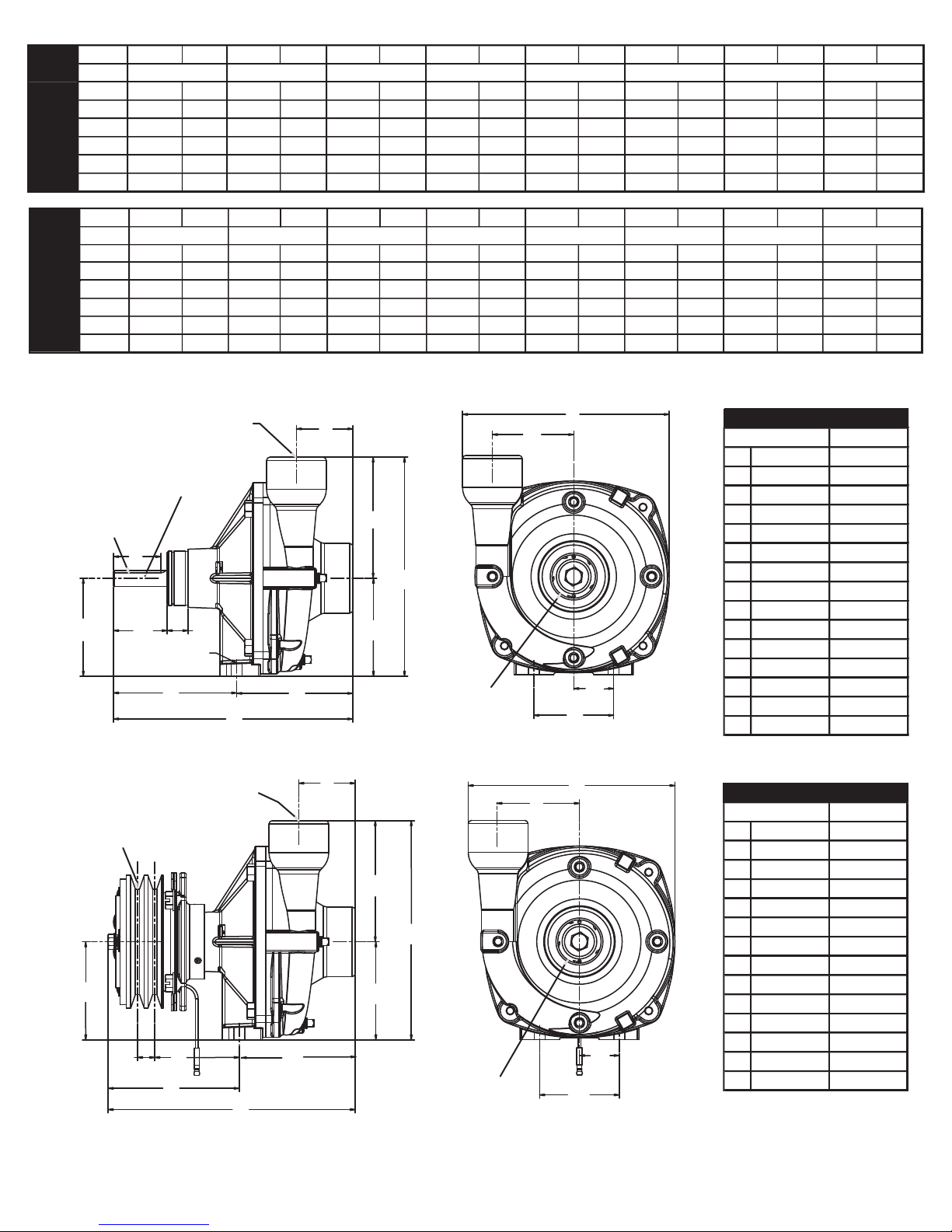
GPM at HP GPM at HP GPM at HP GPM at HP GPM at HP GPM at HP GPM at HP GPM at HP
RPM
2400 80 1.9 65 1.8 26 1.3
3600 105 5.3 105 5.3 92 5.0 50 3.7
4200 122 8.2 120 7.9 115 7.7 98 7.1 56 5.3
5000 140 12.6 140 12.6 138 12.6 130 12.2 118 11.6 88 9.9 45 7.2
5500 140 14.9 140 14.9 138 14.9 135 15.2 130 15.2 118 14.4 90 12.5 60 9.8
6000 140 17.1 140 17.1 140 17.5 140 18.0 135 18.2 130 18 125 18.2 100 16.3
10 PSI
20 PSI
60 PSI
80 PSI
100 PSI
120 PSI
40 PSI
140 PSI
LPM at HP LPM at HP LPM at HP LPM at HP LPM at HP LPM at HP LPM at HP LPM at HP
RPM
2400 303 1.9 246 1.8 98 1.3
3600 397 5.3 397 5.3 348 5.0 189 3.7
4200 462 8.2 454 7.9 435 7.7 371 7.1 212 5.3
5000 530 12.6 530 12.6 522 12.6 492 12.2 447 11.6 333 9.9 170 7.2
5500 530 14.9 530 14.9 522 14.9 511 15.2 492 15.2 447 14.4 341 12.5 227 9.8
6000 530 17.1 530 17.1 530 17.5 530 18.0 511 18.2 492 18 473 18.2 379 16.3
0.7 BAR
1.4 BAR
2.8 BAR
4.1 BAR
5.5 BAR
6.9 BAR
8.3 BAR
9.7 BAR
mm
A 2.12
B 3.69
C 0.65
D 3.18
E 4.93
F 9.31
G 4.32
H 3.69
I 8.25
J 4.56
K 7.78
L 3.11
M 3
N 1.5
Dimensions
Inches
mm
A 2.13 54
B 1.78 45.2
C 3.69 93.7
D 2.02 51.3
E 0.78 19.9
F 4.64 117.8
G 9.01 228.9
H 4.37 111.1
I 3.69 93.7
J 8.25 209.6
K 4.56 115.9
L 7.78 197.7
M 3.06 77.8
N 3 76.2
O 1.5 38.1
Dimensions
Inches
A
ALL 9203 SERIES
1-1/4"-11-1/2" NPT
OUTLET PORT
3/32" X 3/16"
KEYWAY
B
C
.41" DIAM.
THRU HOLE (2)
D
E
F
H
G
1-1/4"-11-1/2" NPT
OUTLET PORT
5" DOUBLE
GROOVE A
SECTION
PULLEY
B
C
D
E
F
G
A
A
K
J
I
1-1/2"-11-1/2" NPT
INLET PORT
J
I
H
1-1/2"-11-1/2"
NPT INLET
PORT
M
9203C
L
O
N
9263
K
L
53.8
93.7
16.5
80.7
125.3
236.4
109.7
93.7
209.6
115.9
197.7
78.9
N
76.2
38.1
M
Page 12
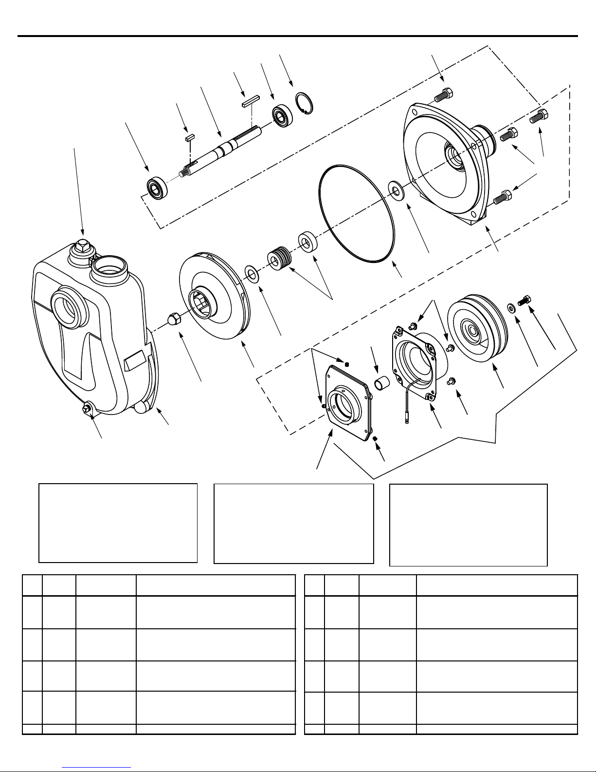
Qnty. Ref. Qnty.
No. Req'd. Part No. Description No. Req'd. Part No. Description
1 1 2406-0007 Drain Plug 12 2 2000-0010 Ball Bearing
2 1 0150-9070C Self Priming Chamber 13 1 1610-0015 Key
3 1 2253-0002 Impeller Nut 14 1 0505-9200 Pump Shaft
4 1 0401-9100P Impeller (Nylon) 15 1 1610-0004 Key
5 1 1700-0100 Gasket (use with Buna and Viton only) 16 1 1820-0013 Bearing Retainer
6 1 2120-0008 Mechanical Seal ( Optional Buna-N) 17 1 2210-0003 Bolt
6 1 2120-0009 Mechanical Seal ( Standard Viton) 18 1 2270-0092 Retaining washer
6 1 3430-0589 Mechanical Seal ( Opt. Silicon Carbide) 19 1 2526-0012 Clutch (Model 9263C-C-SP)
7 1 1720-0083 O-Ring 20 4 N/A Bolt (Part of Clutch Assy)
8 1 1410-0056 Slinger Ring 21 1 1410-0107 Spacer
9 1 0750-9200C3 Mounting Flange 22 3 2230-0001 Set Screw
10 4 2210-0020 Bolt 23 1 0753-9200C Mounting Bracket
11 1 2406-0001 Priming Port Plug 24 1 3430-0592 Complete Clutch Kit
Model 9203C-SP and 9263C-C-SP
11
12
13
14
15
12
16
10
10
8
7
20
6
9
22
5
4
3
2
1
23
Standard Seal Kit Number
No 3430-0332 consists of:
(1) Ref. 5 Gasket
(1) Ref. 6 Mech. seal (Viton)
Silicon Carbide Seal Kit
No. 3430-0589 consists of:
(1) Ref. 6 Mechanical seal
(1) Ref. 7 O-Ring
(1) Ref. 7 O-Ring
21
2020
19
24
22
Note: When ordering parts, give
quantity, part number, description
and complete model number.
Reference numbers are used
ONLY to identify parts in the
drawing and NOT to be used as
order numbers.
Form 300AG-3 9-03
17
18
1
9
Page 13
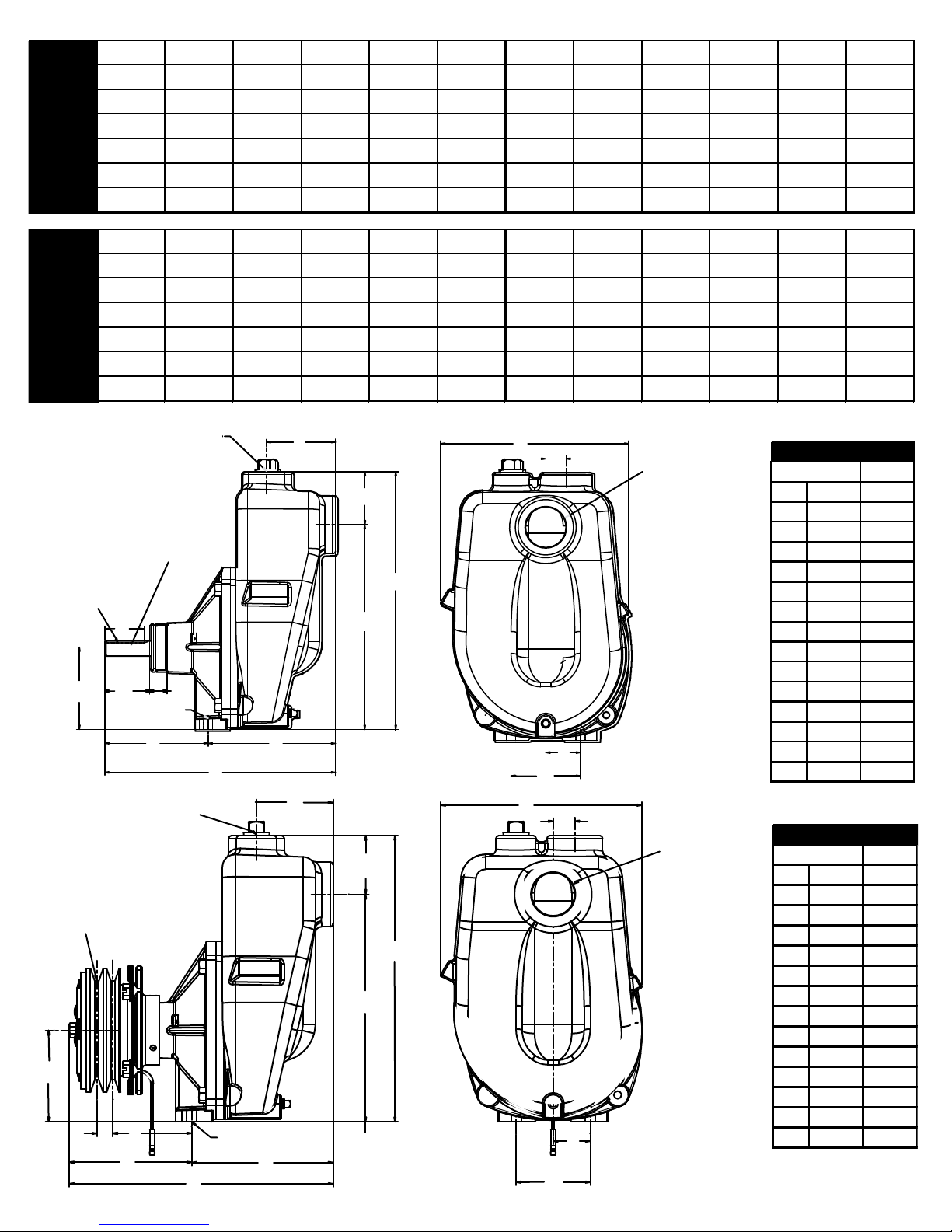
GPM at GPM at GPM at GPM at GPM at GPM at GPM at GPM at GPM at GPM at GPM at
RPM 20 PSI 30 PSI 40 PSI 50 PSI 60 PSI 70 PSI 80 PSI 90 PSI 100 PSI 110 PSI 120 PSI
3600 101 84 60 25
4200 118 112 97 79 54 23
5000 121 120 119 117 110 96 78 52 25
5500 121 120 119 118 116 115 110 96 79 53 29
6000 121 120 119 118 116 115 114 113 110 99 82
LPM at LPM at LPM at LPM at LPM at LPM at LPM at LPM at LPM at LPM at LPM at
RPM 1.4 BAR 2.1 BAR 2.8 BAR 3.4 BAR 4.1 BAR 4.8 BAR 5.5 BAR 6.2 BAR 6.9 BAR 7.6 BAR 8.3 BAR
3600 382 318 227 95
4200 447 424 367 299 204 87
5000 458 454 450 443 416 363 295 197 95
5500 458 454 450 447 439 435 416 363 299 201 110
6000 458 454 450 447 439 435 432 428 416 375 310
mm
ABC
D
E
F
GHIJK
LMN
Dimensions
Inches
mm
A
B
CDEFG
H
I
JKL
MNO
Dimensions
Inches
9203C-SP
9263C-SP
9203C-SP
9263C-SP
1-1/4"-11-1/2" NPT
OUTLET PORT
A
5/8" (15.88)
SHAFT
3/32" x 3/16"
KEYWAY
B
E
D
C
0.41" DIAM.
THRU HOLE (2)
F
H
G
1-1/4"-11-1/2" NPT
A
OUTLET PORT
5" DOUBLE
GROOVE A
SECTION
PULLEY
B
C
D
E
0.41" DIAMETER
THRU HOLE (2)
F
G
H
K
L
O
1-1/2"-11-1/2"
NPT INLET
PORT
J
I
N
M
K
L
1-1/2"-11-1/2"
NPT INLET
9203C-SP
3.09
1.78
3.69
2.02
0.78
4.66
10.36
5.72
9.19
11.57
2.38
8.12
3.00
1.50
0.88
78.5
45.2
93.7
51.3
19.8
118.4
263.1
145.3
233.4
293.9
60.5
206.2
76.2
38.1
22.4
9263C-SP
PORT
I
3.09
3.69
0.65
3.18
J
4.93
5.72
10.65
9.19
2.38
11.57
8.12
0.88
3.00
N
1.50
78.5
93.7
16.5
80.8
125.2
145.3
270.5
233.4
60.5
293.9
206.2
22.4
76.2
38.1
M
Page 14
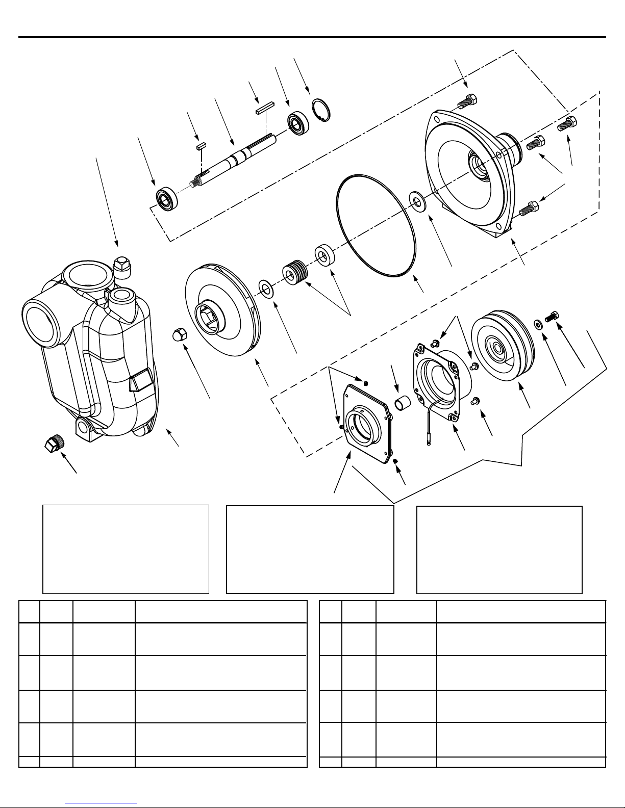
Model 9203C-R-SP and 9263C-CR-SP
11
12
13
14
15
12
16
10
10
8
7
20
6
9
22
5
4
3
2
1
23
Standard Seal Kit
No. 3430-0332 consists of:
(1) Ref. 5 Gasket
(1) Ref. 6 Mech. seal (Viton)
Silicon Carbide Seal Kit
No. 3430-0589 consists of:
(1) Ref. 6 Mechanical seal
(1) Ref. 7 O-Ring
(1) Ref. 7 O-Ring
Qnty. Ref. Qnty.
No. Req'd. Part No. Description No. Req'd. Part No. Description
1 1 2406-0002 Drain Plug
2 1 0152-9070C Self Priming Chamber
3 1 2253-0002 Impeller Nut
4 1 0403-9100P Impeller (Nylon)
5 1 1700-0100 Gasket
6 1 2120-0008 Mechanical Seal (Optional Buna-N)
6 1 2120-0009 Mechanical Seal (Standard Viton)
6 1 3430-0589 Mechanical Seal (Opt. Silicon Carbide)
7 1 1720-0083 O-Ring
8 1 1410-0056 Slinger Ring
9 1 0750-9200C3 Mounting Flange
10 4 2210-0020 Bolt
11 1 2406-0001 Priming Port Plug
12 2 2000-0010 Ball Bearing
13 1 1610-0015 Key
14 1 0505-9200 Pump Shaft
15 1 1610-0004 Key
16 1 1820-0013 Bearing Retainer
17 1 2210-0003 Bolt
18 1 2270-0092 Retaining washer
19 1 2526-0012 Clutch (Model 9263C-CR- SP)
20 4 N/A Bolt (Part of Clutch Assy)
21 1 1410-0107 Spacer
22 3 2230-0001 Set Screw
23 1 0753-9200C Mounting Bracket
24 1 3430-0592 Complete Clutch Kit
21
19
20
19
24
22
Note: When ordering parts, give
quantity, part number, description
and complete model number.
Reference numbers are used
ONLY to identify parts in the
drawing and NOT to be used as
order numbers.
Form 300AG-4 9-03
17
18
Page 15
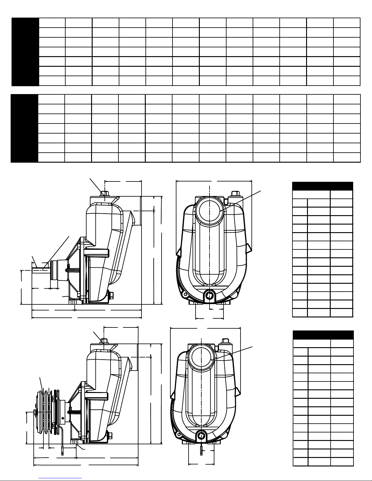
GPM at GPM at GPM at GPM at GPM at GPM at GPM at GPM at GPM at GPM at GPM at
RPM 20 PSI 30 PSI 40 PSI 50 PSI 60 PSI 70 PSI 80 PSI 90 PSI 100 PSI 110 PSI 120 PSI
3600 80 64 43 17
4200 102 90 76 59 38 16
5000 127 119 109 99 86 70 55 37 18
5500 135 131 125 118 110 98 83 71 57 40 21
6000 138 135 132 127 122 117 111 103 93 80 67
9203C-R-SP
9263C-CR-SP
LPM at LPM at LPM at LPM at LPM at LPM at LPM at LPM at LPM at LPM at LPM at
RPM 1.4 BAR 2.1 BAR 2.8 BAR 3.4 BAR 4.1 BAR 4.8 BAR 5.5 BAR 6.2 BAR 6.9 BAR 7.6 BAR 8.3 BAR
3600 303 242 163 64
4200 386 341 288 223 144 61
5000 481 450 413 375 326 265 208 140 68
5500 511 496 473 447 416 371 314 269 216 151 79
6000 522 511 500 481 462 443 420 390 352 303 254
9203C-R-SP
mm
A
B
CDE
F
G
H
I
JKLMN
Dimensions
Inches
mm
A
BCDEF
GHIJK
LMN
Dimensions
Inches
9263C-CR-SP
1 1/4"- 11 1/2 NPT
OUTLET PORT
A
5/8" SHAFT
3/32" x 3/16"
KEYWAY
B
C
.41" DIA. THRU
HOLE (2)
D
E
F
H
G
1 1/4"- 11 1/2 NPT
A
OUTLET PORT
5" DOUBLE
GROOVE
A SECTION
PULLEY
B
C
D
E
.41" DIA.
THRU HOLE (2)
F
G
H
1 1/2"- 11 1/2"
9203C-R-SP
4.00
1.78
3.69
2.02
0.78
4.64
11.89
7.25
10.13
11.69
1.56
8.20
3.00
1.50
101.6
45.2
93.7
51.3
19.8
117.9
302.0
184.2
257.3
296.9
39.6
208.3
76.2
38.1
K
L
NPT INLET
PORT
J
I
N
M
K
1 1/2"- 11 1/2"
9203C-CR-SP
NPT INLET
PORT
I
J
L
M
4.00
3.69
0.65
3.18
4.93
7.25
12.18
10.13
1.56
11.69
8.20
1.50
3.00
1.50
101.6
93.7
16.5
80.8
125.2
184.2
309.4
257.3
39.6
296.9
208.3
38.1
76.2
38.1
Page 16
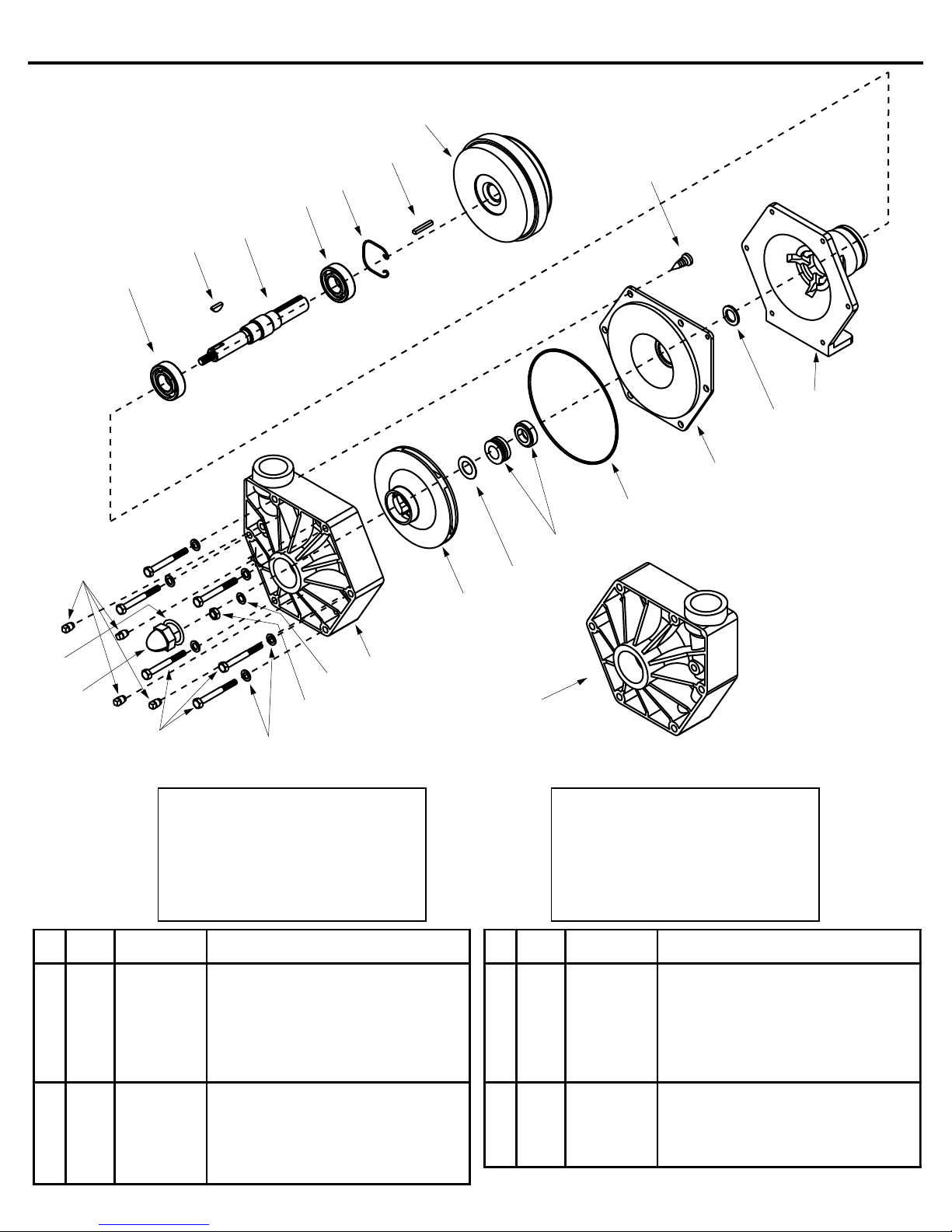
Models 9203P-S, 9253P-C, 9500P-S and 9553P-C
Qnty. Part Ref. Qnty. Part
No. Req'd. No. Description No. Req'd. No. Description
1 1 0700-9000P Pump Casing (9203P-S, 9253P-C) 11 1 0507-9200 Shaft (316 Stainless Steel)
1A 1 0701-9500P Pump Casing (9500P-S, 9553P-C) 12 1 1820-0025 Retaining Ring
2 1 0403-9000P Impeller (Polypropylene) 9203P-S, 9253P-C 13 1 1610-0004 Key
2A 1 0402-9000P Impeller (Polypropylene) 9500P-S, 9553P-C 14 1 2526-0011 Clutch (Models 9253P-C and 9553P-C only)
3 1 1700-0101 Gasket 15 4 2406-0020 Plug
4 1 2120-0011 Mechanical Seal 16 6 2210-0087 Hex head Bolt
5 1 1721-0083 17 6 2270-0041 Washer
6 1 0750-9000P Back Cover (9203P-S, 9253P-C) 18 1 2250-0051 Jam Nut
6A 1 0700-9500P Back Cover (9500P, 9553P-C) 19 1 2270-0057 Washer
7 1 1410-0083 Slinger Ring 20 1 1700-0097 Gasket
8 1 0702-9200C Flange 21 1 2250-0052 Impeller Nut
9 2 2008-0001 Bearing 22 1 2210-0088 Screw
10 1 1610-0042 Woodruff Key (Stainless Steel)
14
13
12
9
22
20
21
15
10
11
9
8
7
6
5
4
3
2
1
19
18
1A
16
SEAL KIT FOR ALL MODELS
No. 3430-0333 consists of:
(1) Ref. 3 Gasket
(1) Ref. 4 Mechanical Seal
(1) Ref. 5 O-ring
(1) Ref. 19 Washer
(1) Ref. 20 Gasket
O-ring
17
Note: When ordering parts, give
quantity, part number, description
and complete model number.
Reference numbers are used
ONLY to identify parts in the
drawing and NOT to be used as
order numbers.
Form 300AG-5 9-03
Page 17
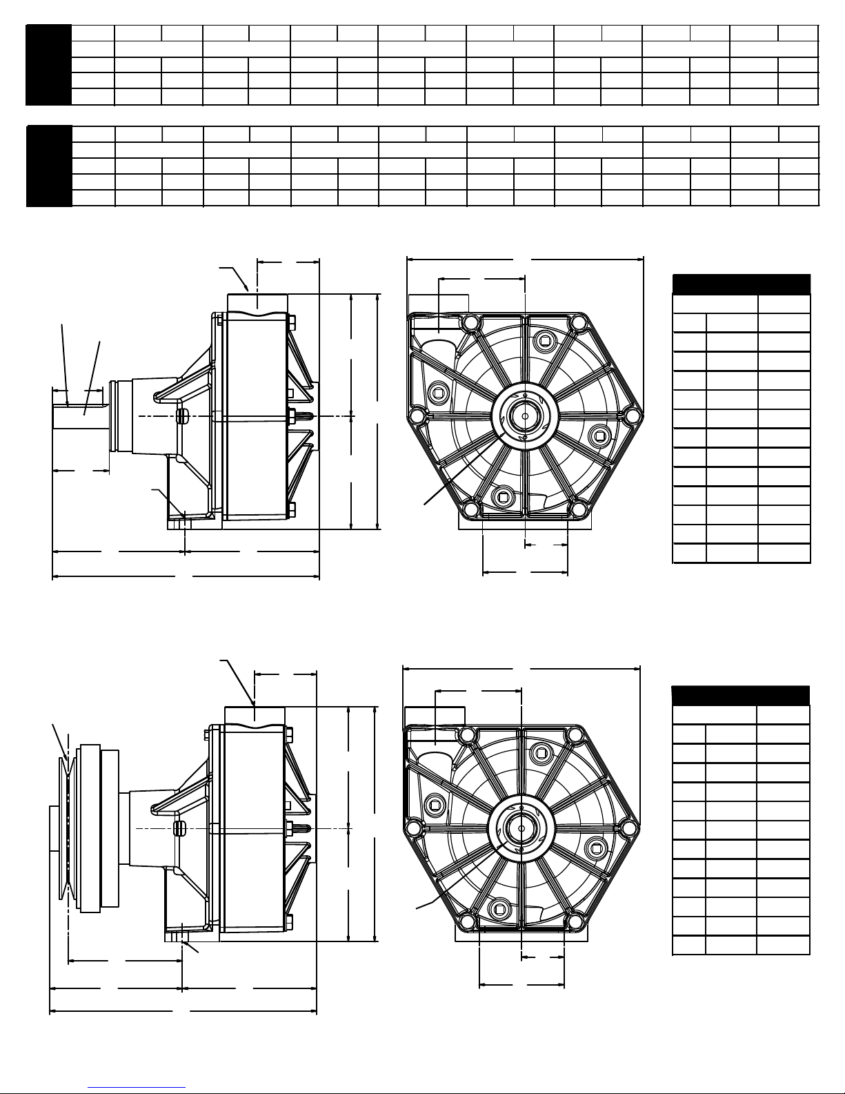
2400 63 1.5 49
LPM at HP LPM at HP LPM at H P LPM at HP LPM at HP LPM at HP LPM at HP LPM at HP
RPM
0.7 BAR
1.4 BAR
2.1 BAR
2.8 BAR
3.4 BAR
4.1 BAR
4.8 BAR
5.5 BAR
GPM at HP GPM at HP GPM at H P GPM at H P GPM at HP GPM at HP GPM at H P GPM at H P
RPM
10 PSI
20 PSI
30 PSI
40 PSI
50 PSI
60 PSI
70 PSI
80 PSI
mm
A
B
C
D
E
F
G
H
I
J
K
L
Dimensions
Inches
mm
A
BCDEFGHIJ
KLM
Dimensions
Inches
3600 91 4.4 87 4.3
9203P-S
9253P-C
4200 103 6.7 101 6.6 98 6.5 90 6.3 82
2400 238 1.5 185 1.4 110 1.1
3600 344 4.4 329 4.3 307 4.1 265 3.9
9203P-S
9253P-C
4200 390 6.7 382 6.6 371 6.5 341 6.3 310 6.0
3/32" x
3/16"
KEYWAY
B
C
0.41" DIAM.
THRU HOLE
(2)
1-1/4" - 11-1/2"
NPT OUTLET
PORT
7/8" (22.2)
SHAFT
D
E
1.4 29 1.1
81 4.1 70
A
F
G
I
H
1-1/2" 11-1/2"
NPT
INLET
PORT
3.9 58 3.6 39 3.6
6.0 71 5.7 60 5.2 42 4.5
220 3.6 148 3.1
269 5.7 227 5.2 159 4.5
J
K
M
L
9203P
2.19
1.78
2.02
4.7
9.45
4.75
4
8.31
4.31
8.38
3.06
3
1.5
55.6
45.2
51.3
119
240
121
102
211
109
213
77.7
76.2
38.1
5-1/2"
SINGLE
GROOVE A
SECTION
PULLEY
B
C
1-1/4" 11-1/2"
NPT
OUTLET
PORT
D
E
A
H
I
9253P-C
J
2.19
4.05
4.7
9.45
4.75
G
4
8.31
F
4.31
8.38
3.06
1-1/2" 11-1/2"
NPT INLET
PORT
L
K
3
1.5
55.6
103
119
240
121
102
211
109
213
77.7
76.2
38.1
Page 18
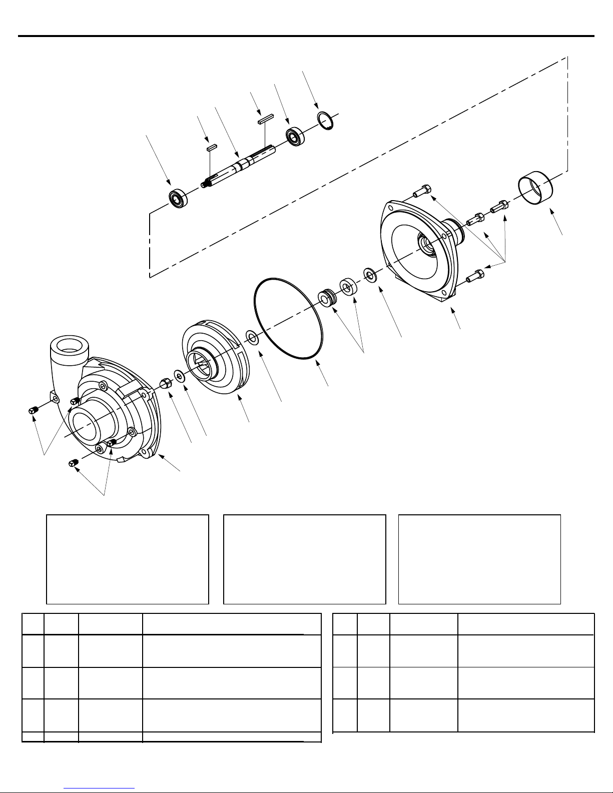
13
Ref. Qnty. Ref. Qnty.
No. Req'd. Part No. Description No. Req'd. Part No. Description
1 4 2406-0007 Drain Plug 9 1 1410-0056 Slinger Ring
2 1 0151-9200C Pump Casing (Includes SS wear ring) 10 1 0750-9200C3 Mounting Flange
3 1 2253-0002 Impeller nut 11 4 2210-0020 Bolt
4 1 2270-0071 Washer 12 1 2300-0025 Protective Cover
5 1 0401-9200P1 Impeller (Nylon) 13 2 2000-0010 Ball Bearing
6 1 1700-0100 Gasket 14 1 1610-0053 Key
7 1 1720-0083 O-Ring 15 1 0505-9200 Pump Shaft
8 1 2120-0008 Mechanical Seal (Optional Buna-N) 16 1 1610-0004 Key
8 1 2120-0009 Mechanical Seal (Standard Viton) 17 1 1820-0013 Bearing Retainer
8 1 3430-0589 Mechanical Seal (Silicon Carbide Opt.)
Model 9204C
17
13
16
15
14
12
11
1
1
Seal Kit for 9204C (STD)
No. 3430-0332 consists of:
(1) Ref. 6 Gasket
(1) Ref. 7 O-Ring
(1) Ref. 8 Mechanical seal
9
8
7
6
5
4
3
2
Seal Kit (Silicon Carbide)
No. 3430-0589 consists of:
(1) Ref. 7 O-Ring
(1) Ref. 8 Mechanical seal
Note: When ordering parts, give
quantity, part number, description
and complete model number.
Reference numbers are used
ONLY to identify parts in the
drawing and NOT to be used as
order numbers.
10
Form 300AG-6 9-03
Page 19
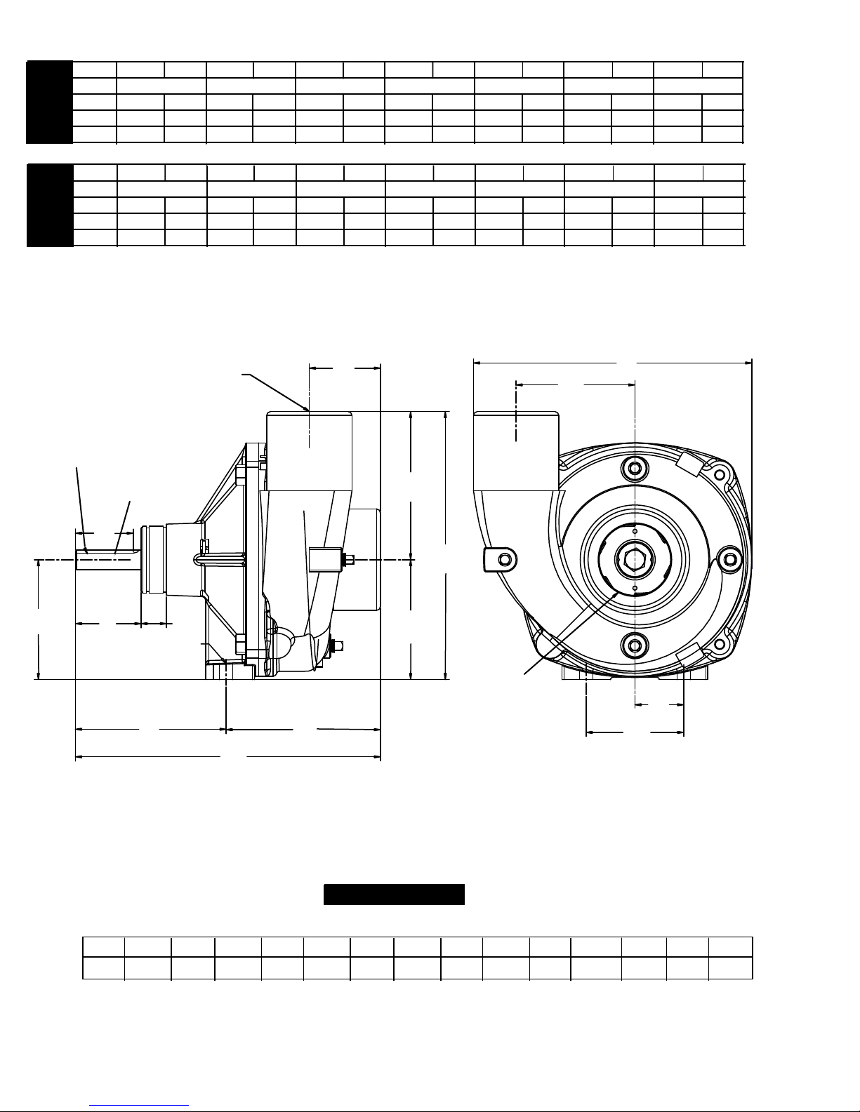
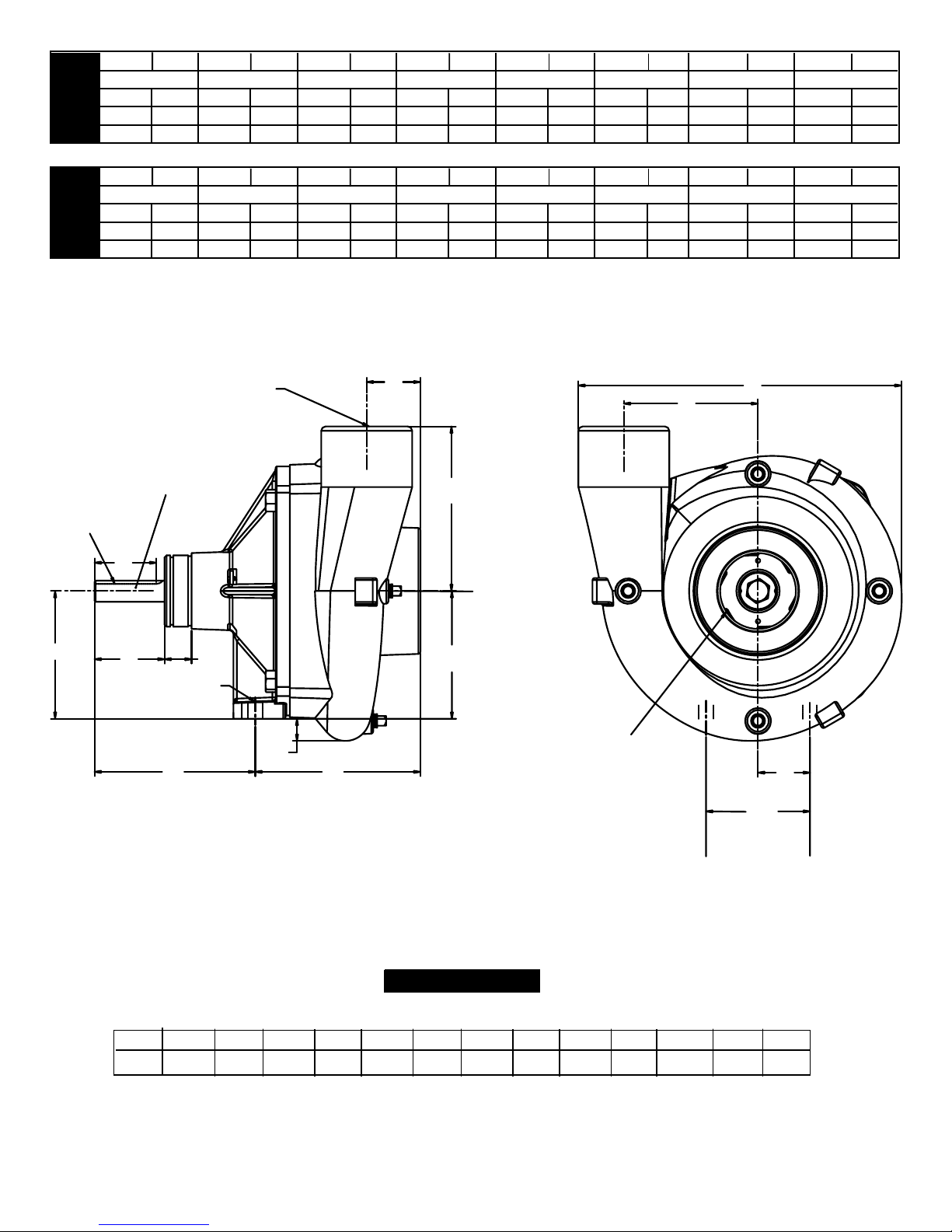
LPMat HP LPM at HP LPM at HP LPMat HP LPMat HP LPMat HP LPMat HP
RPM
0.7 BAR
1.4 BAR
2.1 BAR
2.8 BAR
3.4 BAR
4.1 BAR
4.8 BAR
GPMat HP GPM at HP GPM at HP GPMat HP GPMat HP GPM at HP GPM at HP
10 PSI
20 PSI
30 PSI
40 PSI
50 PSI
60 PSI
70 PSI
RPM
2400 155 2.5 100
3600 190 6.3 190 6.9
9204C9204C
4200 190 9.1 190 9.2 190 10.0 190 10.4 187
2400 578 2.5 379 2.2
3600 719 6.3 719 6.9 712 7.1 644 6.9
4200 719 9.1 719 9.2 719 10.0 719 10.4 708 10.5
2.2
188 7.1 170
6.9 100 5.6
1-1/2" 11-1/2"
NPT
A
OUTLET
PORT
3/32" x
3/16"
KEYWAY
5/8"
(15.88)
SHAFT
K
10.5 165 10.0 115 8.3
379 5.6
625 10.0 435 8.3
L
M
C
B
J
D
E
I
0.41" DIAM
THRU HOLE (2)
2"-11-1/2"
NPT INLET
F
H
PORT
G
9204C
Dimensions
ABCDEFGHI JKL NOM
O
N
Inches
mm
2.19 1.78 3.69 0.78 4.64 4.75 4.563.69 8.252.02 8.569.39 33.66 1.5
55.6 76.2 38.145.2 93.7 51.3 19.8 93.7 116 217210118 239 121 93
Page 20
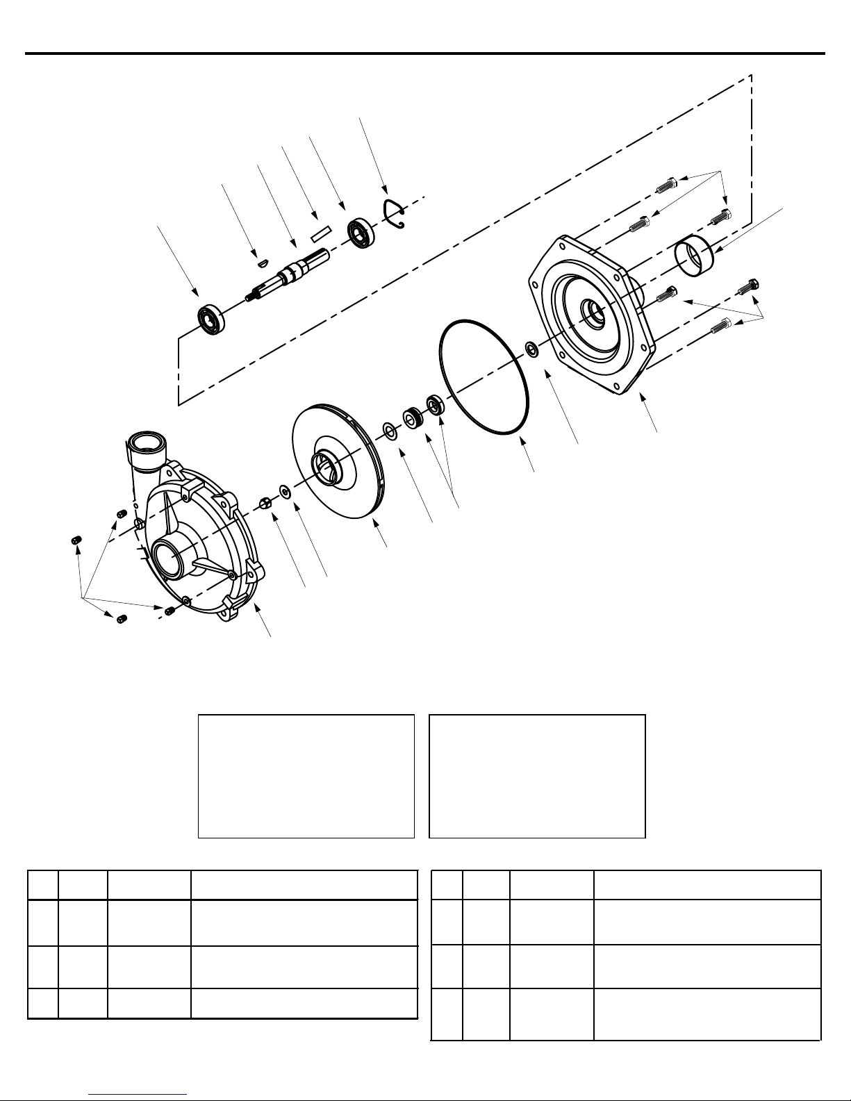
13
Ref. Qnty. Ref. Qnty.
No. Req'd. Part No. Description No. Req'd. Part No. Description
1 4 2406-0007 Drain Plug 9 1 1410-0083 Slinger Ring
2 1 0152-9200C Pump Casing 10 1 0751-9200C Mounting Flange
3 1 2253-0002 Impeller Nut 11 6 2210-0086 Bolt
4 1 2270-0071 Washer 12 1 2300-0035 Protective Cover
5 1 0403-9200P Impeller (Nylon) 13 2 2008-0001 Ball Bearing
6 1 1700-0101 Gasket 14 1 1610-0012 Key
7 1 2120-0011 Mechanical Seal (Viton) 15 1 0507-9200 Pump Shaft
8 1 1720-0180 O-Ring 16 1 1820-0025 Bearing Retainer
14
15
17
Model 9205C
16
13
11
12
11
9
8
7
6
5
4
1
Seal Kit for 9205C
No. 3430-0537 consists of:
(1) Ref. 6 Gasket
(1) Ref. 7 Mechanical seal
(1) Ref. 8 O-Ring
3
2
Note: When ordering parts, give
quantity, part number, description
and complete model number.
Reference numbers are used
ONLY to identify parts in the
drawing and NOT to be used as
order numbers.
10
17 1 1610-0004 Key
Form 300AG-7 9-03
Page 21
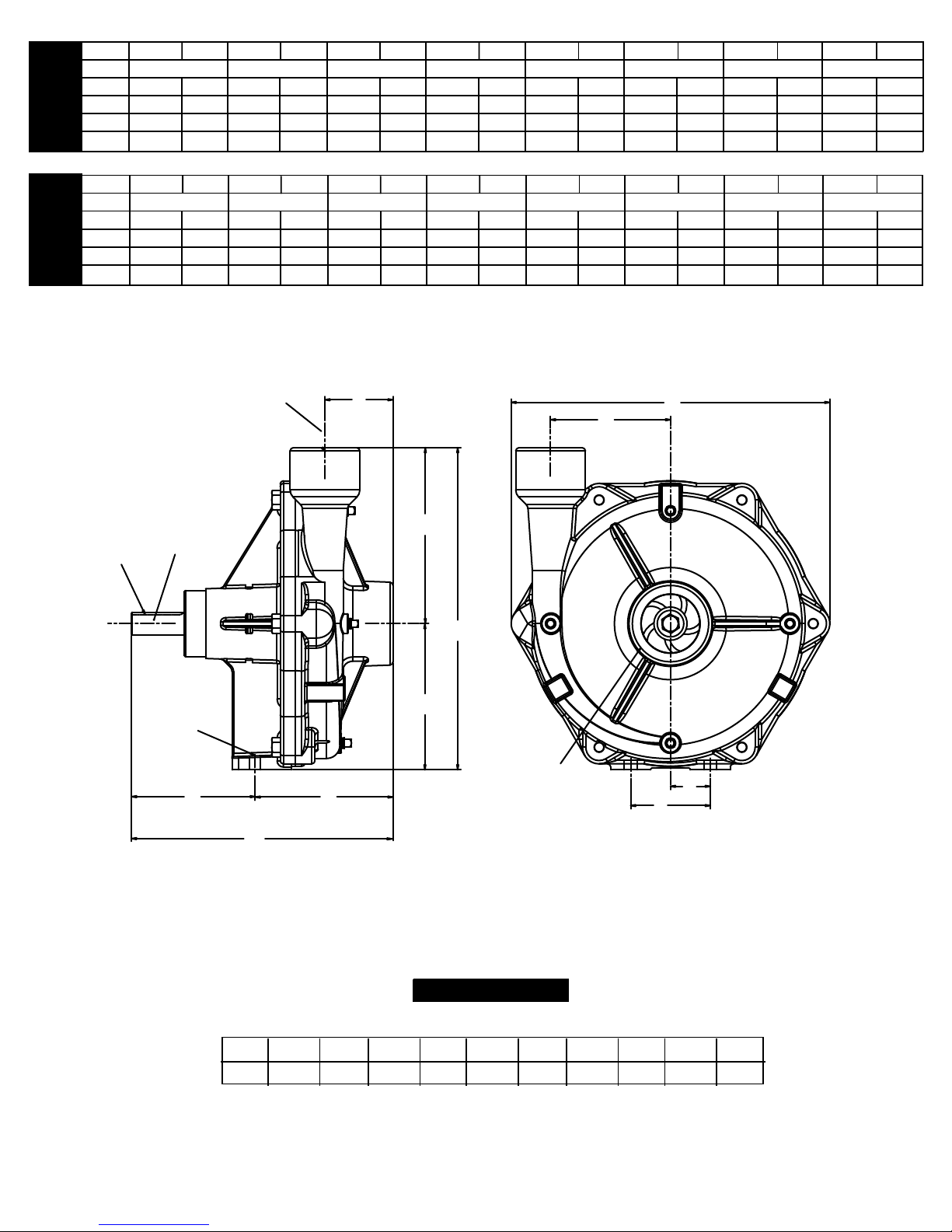
LPMat HP LPM at HP LPM at HP LPMat HP LPMat HP LPMat HP LPMat HP LPM at HP
RPM
1.4 BAR
2.8 BAR
4.1 BAR
5.5 BAR
6.9 BAR
8.3 BAR
9.7 BAR
11.0 BAR
3000 165 11.4 164
GPMat HP GPM at HP GPM at HP GPMat HP GPMat HP GPM at HP GPM at HP GPMat HP
RPM
20 PSI
40 PSI
60 PSI
80 PSI
100 PSI
120 PSI
140 PSI
160 PSI
3400 175 14.8 175 15.5
9205C
9205C
3800 180 18.2 180 18.8
4200
180 21.9 180 22.0 180
11.7
154 11.6
173 16.3
180
19.8
24.0
104
168
178 21.1 173
180 25.3 180
9.5
16.3
127 14.2
43 8.7
21.8 156 20.7
26.9 177 27.9 173 28.1 157 26.4
112 17.5
3000
3400
9205C
3800
4200
3/32" x
3/16"
KEYWAY
625 11.4 621 11.7
662 14.8 662 15.5 655 16.3
681 18.2 681 18.8 681 19.8 674 21.1 655 21.8
681 21.9 681 22.0 681 24.0 681 25.3 681 26.9
583 11.6
394 9.5
636 16.3
481 14.2
1-1/2"11-1/2"
NPT
OUTLET
A
I
PORT
7/8"
(22.2)
G
SHAFT
F
163 8.7
591 20.7 424 17.5
670 27.9 655 28.1 594 26.4
H
0.47 DIAM.
E
DRILL
THRU
HOLES (2)
B
C
D
2"-11-1/2"
NPT
INLET
PORT
K
J
9205C
Dimensions
ABCDEF GHI JK
Inches
2.56 4.66 9.84 6.63 4.525.19 12.05.5 1.5
12.1
mm
3
38.165 76.2118 250 132 140 308 168 305 115
Page 22
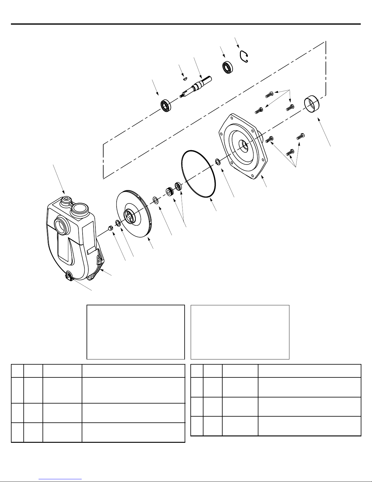
16
Ref. Qnty. Ref. Qnty .
No. Req'd. Part No. Description No. Req'd.Part No. Description
1 1 2406-0002 Drain Plug 10 1 0751-9200C Mounting Flange
2 1 0150-9075C Pump Casing (standard) 11 6 2210-0086 Bolt
2 1 0150-9075C1 Pump Casing (BSP) 12 2 2008-0001 Ball Bearing
3 1 2253-0002 Impeller Nut 13 1 1610-0012 Key
4 1 2270-0071 Washer 14 1 0507-9200 Pump Shaft
5 1 0403-9200P Impeller (Nylon) 15 1 1820-0025 Bearing Retainer
6 1 1700-0101 Gasket 16 1 2406-0034 Priming Port Plug (Standard)
7 1 2120-0011 Mechanical Seal (Standard Viton) 16 1 2406-0036 Priming Port Plug (BSP)
8 1 1720-0180 O-Ring 17 1 2300-0035 Protective Cover
9 1 1410-0083 Slinger Ring
Model 9205C-SP and 9205C-BSP
15
12
14
13
12
11
17
11
10
5
4
3
2
1
Seal and O-ring Repair Kit
No. 3430-0537 consists of:
(1) Ref. 6 Gasket
(1) Ref. 7 O-Ring
(1) Ref. 8 Mechanical seal
9
8
7
6
Note: When ordering parts, give
quantity, part number, description
and complete model number.
Reference numbers are used
ONLY to identify parts in the
drawing and NOT to be used as
order numbers.
Form 300AG-8 9-03
Page 23
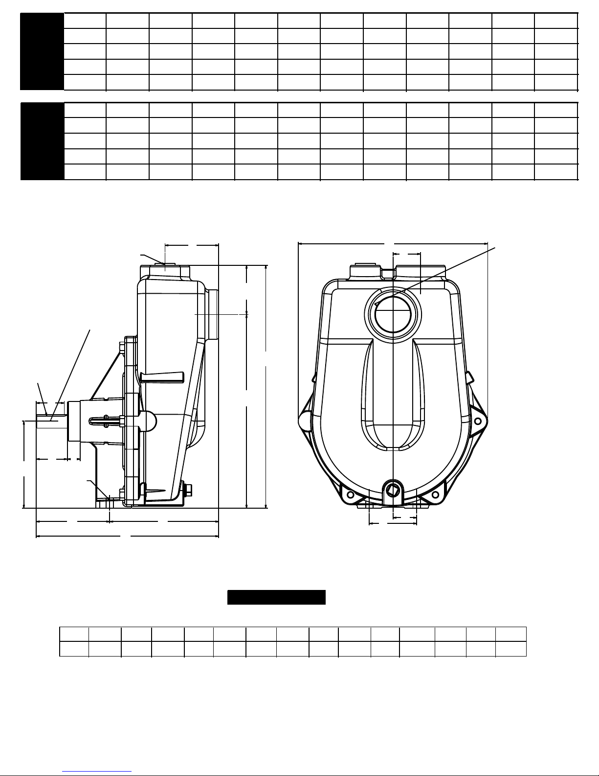
RPM 40 PSI 50 PSI 60 PSI 70 PSI 80 PSI 90 PSI 100 PSI 110 PSI 120 PSI 130 PSI 140 PSI
3400 133 132 131 130
9205C-SP
3600 135 134 133 127 114 54 20
3800 159 159 159 159 159
RPM 2.8 BAR 3.4 BAR 4.1 BAR 4.8 BAR 5.5 BAR 6.2 BAR 6.9 BAR 7.6 BAR 8.3 BAR 9.0 BAR 9.7 BAR
3400 503 500 496 492 435 356
3600 511 507 503 481 432 367
9205C-SP
3800 601 601 601 601 601 601 531 454 363 244 91
GPM at GPM at GPM at GPM at GPM at GPM at GPM at GPM at GPM at GPM at GPM at
115 35
LPM at LPM at LPM at LPM at LPM at LPM at LPM at LPM at LPM at LPM at LPM at
94
97
159
68
80
140 120 96 65 24
257
303
132
204 76
3/32"
X 3/16"
KEYWAY
B
D
C
.47" THRU
HOLE (2)
E
F
7/8"
(22.2)
SHAFT
G
H
A
K
L
O
2"-11-1/2" NPT
(9205C-SP)
2"-11" BSPP
(9205C-BSP)
INLET PORT
J
I
N
M
ABCDEF GHI JK L NOM
Inches
mm
9205C-SP
Dimensions
12. 7 5 15.38 12.0011.563.41 1.78 5.50 0.82 4.66 6.91 3.131.97 1.503.00 1.75
79.586.6 38.1 44.576.245.2 50.0 20.8 304.8390.7139.7 118.4 293.6 175.5 323 . 9
Page 24
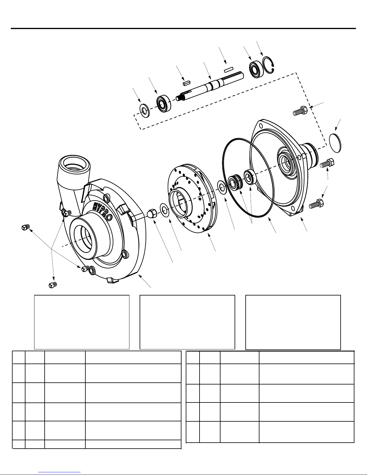
Ref. Qnty. Ref. Qnty.
No. Req'd. Part No. Description No. Req'd. Part No. Description
1 4 2406-0007 Pipe Plug 9206C
1 4 2406-0016 Pipe Plug 9206S
2 1 0154-9200C1 Cover 9206C
8 1 0756-9200S Mounting Flange 9206S
2 1 0154-9200S1 Cover 9206S
9 4 2210-0020 Screw Hex Head 9206C
3 1 2253-0002 Impeller Nut 9206C
9 4 2210-0125 Screw Hex Head 9206S
3 1 2253-0006 Impeller Nut 9206S
10 1 1410-0056 Slinger Ring
4 1 0401-9200P1 Nylon Impeller 9206C
11 2 2000-0010 Bearing
4 1 0405-9200P Poly Impeller 9206S
12 1 1610-0053 Key 9206C
5 1 1700-0100 Gasket (Cast iron only)
12 1 1610-0057 Key 9206S
6 1 2120-0009 Mech. Seal 9206C
13 1 0505-9200 Shaft
6 1 3430-0589 Silicon Carbide Seal 9206S
14 1 1820-0013 Retaining Ring
Model 9206C and 9206S
16
11
14
10
11
12
13
9
17
9
6
5
7
8
1
Seal Kit for 9206C
No. 3430-0332 consists of:
(1) Ref. 5 Gasket
(1) Ref. 6 Mechanical seal
2
Seal Kit for 9206S
No. 3430-0589 consists of:
(1) Ref. 6 Mechanical seal
(1) Ref. 7 O-Ring
5
3
(1) Ref. 7 O-Ring
7 1 1720-0083 O-Ring
8 1 0750-9200C4 Mounting Flange 9206C
15 1 2270-0071 Washer
16 1 1610-0004 Key
17 1 2300-0025 Protective Cover
4
Note: When ordering parts, give
quantity, part number, description
and complete model number.
Reference numbers are used
ONLY to identify parts in the
drawing and NOT to be used as
order numbers.
Form 300AG-9 9-03
Page 25
GPMat HP GPM at HP GPM at HP GPMat HP GPMat HP GPM at HP
10 PSI
20 PSI
30 PSI
40 PSI
50 PSI
60 PSI
0.7 BAR
1.4 BAR
2.1 BAR
2.8 BAR
3.4 BAR
4.1 BAR
171 2.3 114
226 7.0 7.5226 196 7.3 143 6.1226
9206C
9206S
226 9.2 10.7226 226 11.0 225 11.3 202 10.9226
2.0
7.1
9.4
GPMat HP
70 PSI
158 9.5 80 6.4
GPMat HP
80 PSI
LPMat HP LPMat HP LPMat HP LPMat HP LPM at HP LPMat HP
647 2.3 432
856 7.0 7.5856 742 7.3 541 6.1856
9206C
9206S
856 9.2 10.7856 856 11.0 852 11.3 765 10.9856
2.0
7.1
9.4
1-1/2" - 11-1/2"
NPT OUTLET
AK
PORT
5/8" (15.88)
3/32" x
3/16"
SHAFT
J
KEYWAY
LPMat HP
4.8 BAR
598 9.5 303 6.4
LPMat HP
L
5.5 BAR
CDBE
0.41 DIAM
DRILL THRU
TWO HOLES
F
ABCDEF GHI JKL NM
Inches
mm
1.55 1.78 3.69 0.78 4.64 4.77 9.333.69 4.752.02 3.880.64 1.53
39.4 38.145.2 93.7 51.3 19.9 93.7 237 98.4120.7117.8 16.2 121.1 76.2
G
H
I
9206
Dimensions
2"-11-1/2"
NPT INLET
PORT
N
M
MOUNTING
HOLES
Page 26
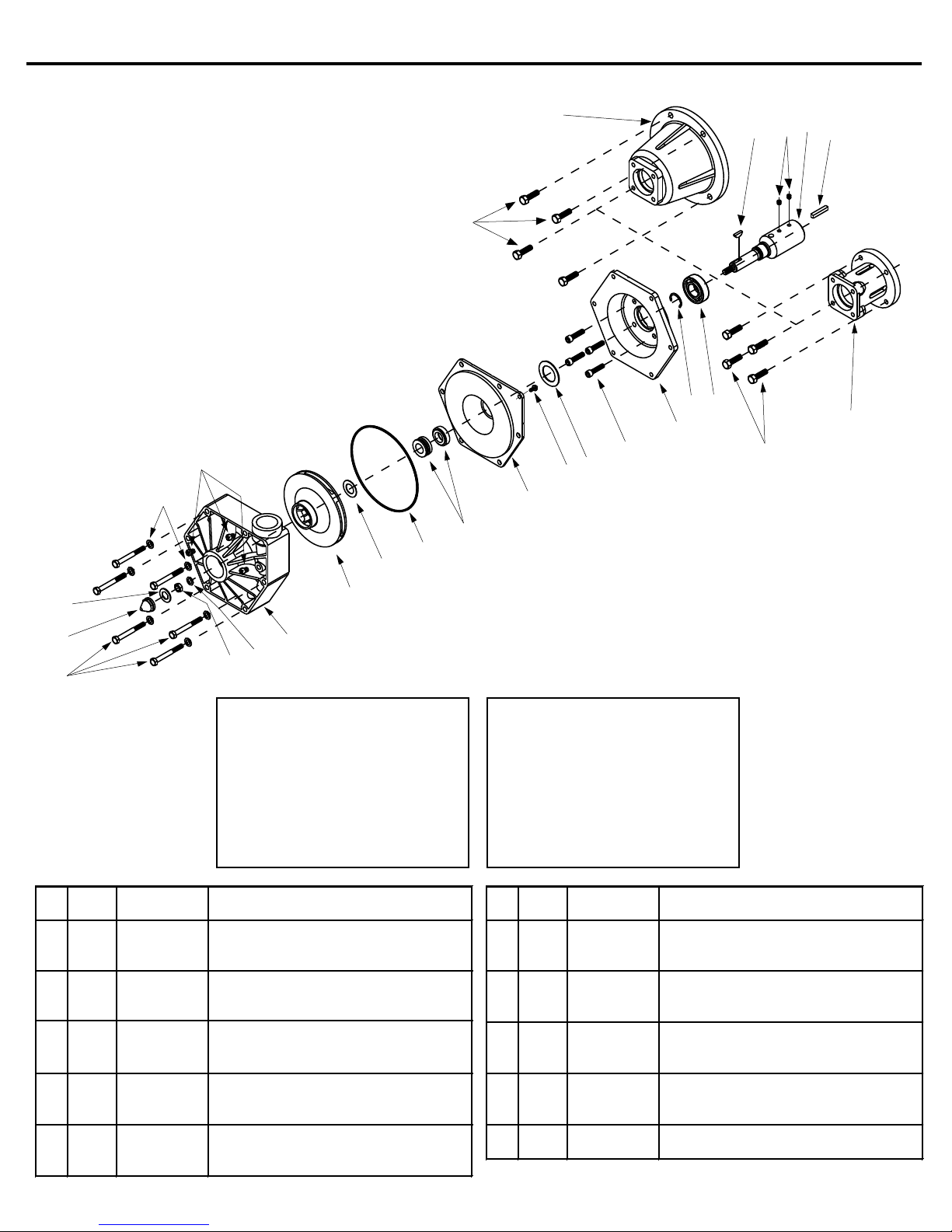
Ref. Qnty. Ref. Qnty.
No. Req'd. Part No. Description No. Req'd. Part No. Description
1 1 0701-9500P Pump Casing 15 1 1610-0004 Key (9513P)
2 1 0402-9000P Impeller (Polypropylene) 16 1 0508-9500 416 Stainess Shaft (Model 9513P)
3 1 1700-0101 Gasket 16 1 0505-9500 Shaft (Model 9510P)
4 1 1721-0083 O-Ring 17 2 2230-0017 Set Screw
5 1 2120-0011 Mechanical Seal 18 1 1610-0042 Woodruff Key (316 SS)
6 1 0700-9500P Back Cover 19 1 0703-9500C Flange (Model 9510P)
7 1 2210-0088 Screw 20 4 2210-0026 Hex head bolt
8 1 1410-0082 Spacer 21 6 2270-0041 Washer
9 4 2220-0055 Socker Head Capscrew 22 1 1700-0097 Gasket
10 1 0702-9500C Intermediate Flange 23 1 2250-0052 Impeller Nut
11 1 1810-0013 Retainer Ring 24 6 2210-0087 Hex Head Capscrew
12 2 2008-0001 Bearing 25 1 2250-0051 Jam Nut
13 4 2210-0077 Hex head bolt 26 1 2270-0057 Washer
14 1 0705-9500C Flange (Model 9513P) 27 4 2406-0020 Plug
15 1 1610-0005 Key (9510P)
Models 9510P and 9513P
(CW Rotation when viewed from shaft end)
21
27
19
18
20
12
11
10
9
8
7
6
5
4
3
13
17
16
15
14
2
Note: When ordering parts, give
quantity, part number, description
and complete model number.
Reference numbers are used
ONLY to identify parts in the
drawing and NOT to be used
as order numbers.
23
24
22
1
26
25
Seal Kit for 9510P, 9513P
No. 3430-0333 consists of:
(1) Ref. 3 Gasket
(1) Ref. 4 O-ring
(1) Ref. 5 Mechanical Seal
(1) Ref. 22 Gasket
(1) Ref. 26 Washer
Form 300AG-10 9-03
Page 27
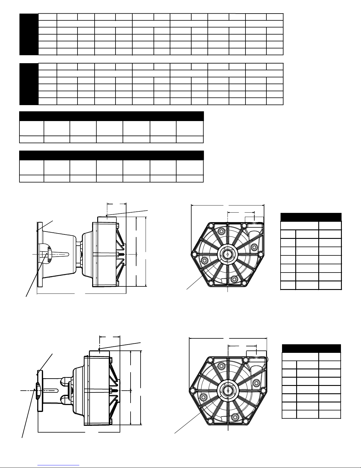
mm
A 2.19
B 8.83
C 3.68
D 7.99
E 4.31
F 8.38
G 3.06
Dimensions
Inches
mm
A
B
10.13
C
DEF
G
Dimensions
Inches
GPM at HP GPM at H P GPM at HP GPM at HP GPM at HP GPM at HP
0 PSI
10 PSI
30 PSI
40 PSI
20 PSI
0.0 BAR
0.7 BAR
2.1 BAR
2.8 BAR
1.4 BAR
RPM
2400 55 1.2 47 1.1 27 0.8
3000 69 2.3 58 2.1 43 1.8
9510P
3450
3600
LPM at H P LPM at HP LPM at HP LPM at H P LPM at HP LPM at HP
RPM
2400 208 1.2 178 1.1 103 0.8
9510P
3000
3450
3600
260 2.3 221 2.1 161 1.8
74 3.3 65 3.2 48 2.8
83 4.5 73 4.2 62 3.9 44 3.3
280 3.3 245 3.2 182 2.8
315 4.5 277 4.2 233 3.9 166 3.3
50 PSI
3.4 BAR
9513P Based on 5.5 Honda Engine
GPM at
0 PSI
92
GPM at
10 PSI
91
GPM at
20 PSI
88
GPM at
30 PSI
81
GPM at
40 PSI
9513P Based on 5.5 Honda Engine
LPM at
0.0 BAR
348
LPM at
0.7 BAR
344
LPM at
1.4 BAR
333
FLANGE MATES
TO A 8HP GAS
LPM at
2.1 BAR
307
A
LPM at
2.8 BAR
ENGINE
B
1" HOLLOW SHAFT 1/4"
SQUARE KEY
70
265
E
C
English Standard
GPM at
50 PSI
58
LPM at
3.4 BAR
220
GPM at
60 PSI
LPM at
4.1 BAR
1-1/4"11-1/2"
NPT
OUTLET
PORT
D
1-1/2"-11-1/2" NPT
OUTLET PORT
42
Metric
159
F
9510P
G
2.19
55.6
257.3
3.68
7.99
4.31
8.38
3.06
93.5
202.9
109.5
212.9
77.7
FLANGE MATES
A
TO AN 5HP GAS
ENGINE
B
3/4" HOLLOW SHAFT 3/16"
SQUARE KEY
E
C
1-1/4"11-1/2"
NPT
OUTLET
PORT
D
1-1/2"-11-1/2" NPT
INLET PORT
F
9513P
G
55.6
224.3
93.5
202.9
109.5
212.9
77.7
Page 28
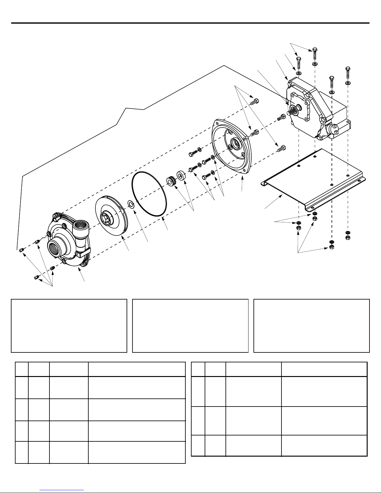
Ref. Qnty. Ref. Qnty.
No. Req'd. Part No. Part No.Description No. Req'd. Description
Models 1536, 1537, 1538, 1539 and 1540
13
14
15
16
1538
Unassembled pump kit
Pump portion only
3
17
9
8
7
6
5
4
10
11
12
2
1
Seal Kit for 1536 thru 1540 (Std.)
No. 3430-0332 consists of:
(1) Ref. 4 Gasket
(1) Ref. 5 O-Ring
(1) Ref. 6 Mechanical seal
1 4 2406-0007 Drain Plug 13 4 2210-0021 Bolt
2 1 0152-9000C Pump Casing (with SS wear ring) 14 4 2270-0040 Washer
3 1 0402-9200P Impeller (Nylon) 15 1 2541-0033 Briggs& Stratton Engine
4 1 1700-0100 Gasket (135232-0035-01)* (Model 1536 and 1539)
5 1 1720-0083 O-ring 15 1 2541-0034 Honda Engine
6 1 2120-0009 Mechanical Seal - Viton GX160K1Type-TX2* (Model1537)
7 4 2210-0098 Bolt 15 1 2541-0035 Honda Engine
8 4 1700-0119 Seal GX160KIT1C3 (Model1540)
9 1 0703-9200C Flange 16 1 1410-0088 Bearing Shield (5 HP Briggs)
10 1 1510-0083 Mounting Plate 16 1 1410-0105 Bearing Shield (5.5 HP Briggs)
11 4 2260-0002 Lock Washer 17 4 2210-0020 Bolt
12 4 2250-0003 Nut
Seal Kit for 1536 thru 1540 (Opt.)
No. 3430-0589 (Silicon carbide)
consists of:
(1) Ref. 5 O-Ring
(1) Ref. 6 Mechanical seal
Note: When ordering parts, give
quantity, part number, description
and complete model number.
Reference numbers are used
ONLY to identify parts in the
drawing and NOT to be used as
order numbers.
* Contact the engine manufacturer for this product number.
Form 300AG-11 9-03
Page 29
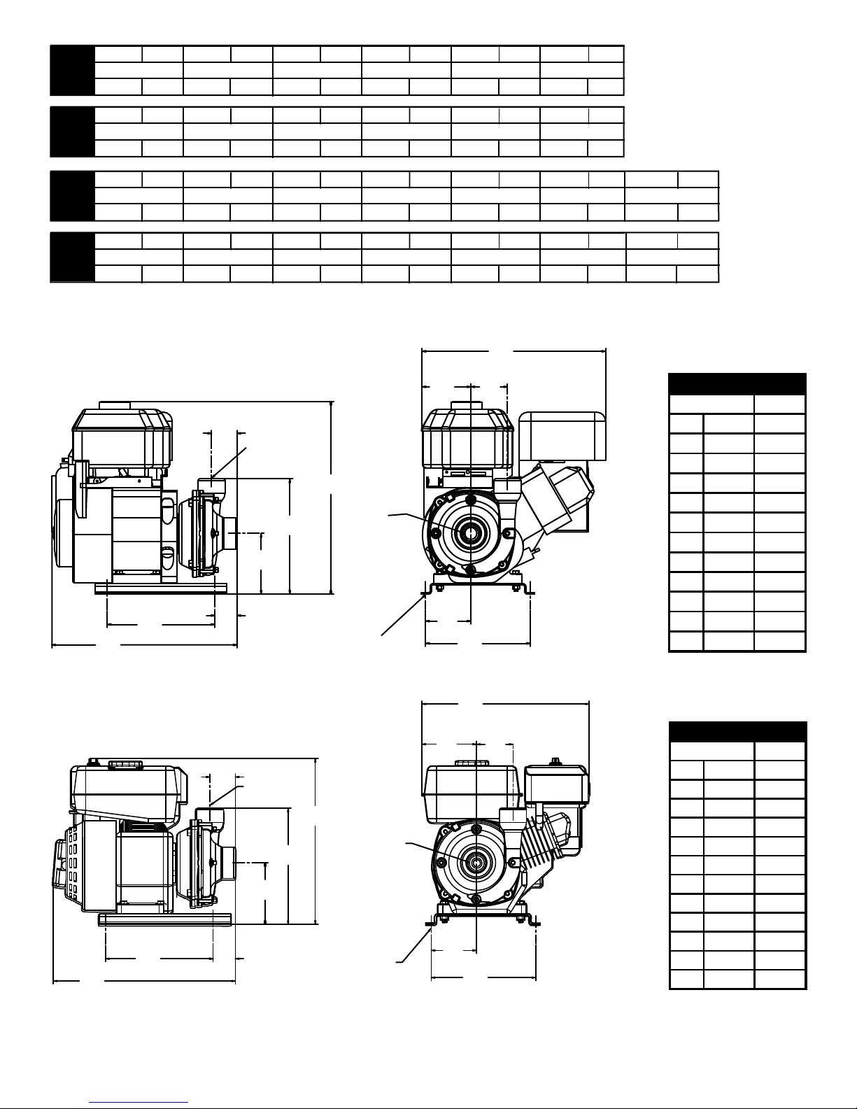
mm
A 2.13 54.1
B 15.48 393.2
C 9.00 228.6
D 1.85 47.0
E 5.08 129.0
F 9.64 244.9
G 16.12 409.4
H 15.34 389.6
I 4.07 103.4
J 3.06 77.7
K 3.78 96.0
L 8.75 222.3
Dimensions
Inches
mm
A 2.30 58.4
B 15.23 386.8
C 9.00 228.6
D 1.85 47.0
E 5.16 131.1
F 9.72 246.9
G 13.89 352.8
H 14.00 355.6
I 4.57 116.1
J 3.78 96.0
K 8.75 222.3
L 3.06 77.7
Dimensions
Inches
104 5.5 94 5.5 82 5.5 70 5.5 50 5.5100
GPMat HP GPM at HP GPM at HP GPMat HP GPMat HP GPM at HP
10 PSI
20 PSI
30 PSI
40 PSI
50 PSI
60 PSI
LPMat HP LPM at HP LPM at HP LPMat HP LPMat HP LPMat HP
0.7 BAR
1.4 BAR
2.1 BAR
2.8 BAR
3.4 BAR
4.1 BAR
GPMat HP GPM at HP GPM at HP GPMat HP GPMat HP GPM at HP
10 PSI
20 PSI
30 PSI
40 PSI
50 PSI
60 PSI
LPMat HP LPM at HP LPM at HP LPMat HP LPMat HP LPMat HP
1539153915401540
1536
5.5
394 5.5 379
1536
110 5.5 96 5.5 88 5.5 80 5.5 60 5.5106
1537
0.7 BAR 1.4 BAR 2.1 BAR 2.8 BAR 3.4 BAR 4.1 BAR 4.8 BAR
416 5.5 401
1537
5.5
5.5
5.5
A
1-1/4" NPT
OUTLET
356
363
F
5.5
5.5
310
333
G
1-1/2" NPT
INLET
5.5
5.5
265
303
5.5
5.5
H
I
J
189
227
5.5
5.5
GPMat HP
70 PSI
60 5.5
LPMat HP
114
5.5
1536
B
B
C
C
D
A
D
E
.38 (9.5) DIA
HOLES (4)
1-1/4"NPT
OUTLET
F
E
.38 (9.5) DIA
HOLES (4)
G
1-1/2" NPT
INLET
K
L
H
I
L
1537
J
K
Page 30
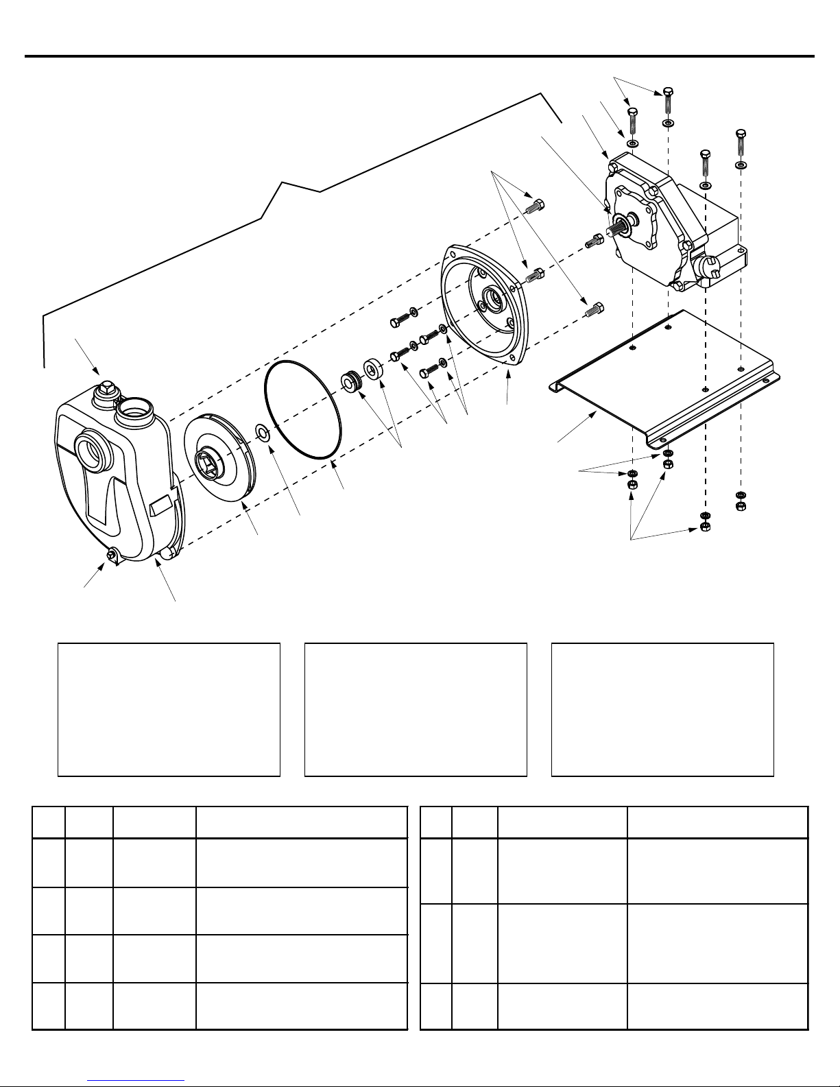
Models 1536-SP, 1537-SP, 1538-SP,1539-SP, and 1540-SP
13
14
15
16
1538-SP
Pump kit less gas engine
18
6
5
17
9
8
7
10
11
4
3
1
2
Seal Kit for 1536 thru 1540
(Std.) No. 3430-0332
consists of:
(1) Ref. 4 Gasket
(1) Ref. 5 O-ring
Seal Kit for 1536 thru 1540
(Opt.) No. 3430-0589
(silicon carbide) consists of:
(1) Ref. 5 O-ring
(1) Ref. 6 Mechanical Seal
(1) Ref. 6 Mechanical Seal
Ref. Qnty. Ref. Qnty.
No. Req'd. Part No. Description No. Req'd. Part No. Description
1 4 2406-0001 Drain Plug 13 4 2210-0021 Bolt
2 1 0152-9070C Pump Casing (with SS w ear ring) 14 4 2270-0040 Washer
3 1 0402-9200P Impeller (Nylon) 15 1 2541-0033 Briggs & Stratton Engine
4 1 1700-0100 Gasket (135232-0035-01)* (Model 1536 and 1539)
5 1 1720-0083 O-ring 15 1 2541-0034 Honda Engine
6 1 2120-0009 Mechanical Seal - Viton GX160K1 Type-TX2* (Model 1537)
7 4 2210-0098 Bolt 15 1 2541-0035 Honda Engine
8 4 1700-0119 Seal GX160KIT1C3* (Model 1540)
9 1 0703-9200C Flange 16 1 1410-0088 Bearing Shield (5 HP Briggs)
10 1 1510-0083 Mounting Plate 16 1 1410-0105 Bearing Shield (5.5 HP Briggs)
11 4 2260-0002 Lock Washer 17 4 2210-0020 Bolt
12 4 2250-0003 Nut 18 1 2406-0002 Prime Port Plug
Note: When ordering parts, give
quantity, part number, description
and complete model number.
Reference numbers are used
ONLY to identify parts in the
drawing and NOT to be used
as order numbers.
12
* CONTACT THE ENGINE MANUFACTURER FOR THIS PRODUCT NUMBER Form 300AG-12 9-03
Page 31
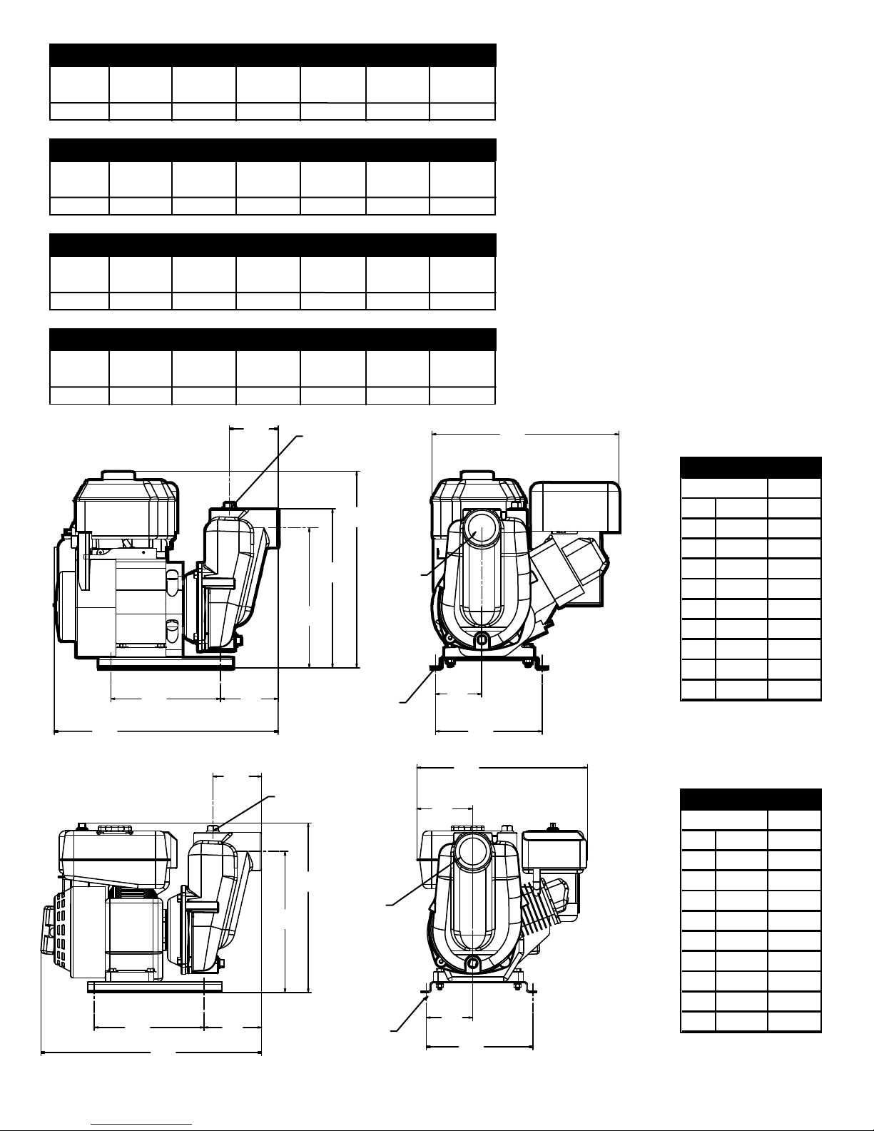
1536-SP, 1539-SP
mm
ABCDE
F
GHI
J
Dimensions
Inches
mm
ABCDE
F
GHI
J
Dimensions
Inches
GPM at
10 PSI
92
GPM at
20PSI
81
GPM at
30 PSI
5.5 HP Briggs & Stratton
GPM at
40 PSI
67
55
GPM at
50 PSI
40
English Standard
GPM at
60 PSI
15
GPM at
70 PSI
1536-SP, 1539-SP
LPM at
0.7 BAR
348
LPM at
1.4 BAR
307
2.1 BAR
1537-SP, 1540-SP
GPM at
10 PSI
98
GPM at
20 PSI
87
1537-SP, 1540-SP
LPM at
0.7 BAR
371
LPM at
1.4 BAR
329
2.1 BAR
C
B
5.5 HP Briggs & Stratton
LPM at
254
GPM at
30 PSI
73
LPM at
276
LPM at
2.8 BAR
208
5.5 HP Honda
GPM at
40 PSI
5.5 HP Honda
LPM at
2.8 BAR
227
A
D
60
LPM at
3.4 BAR
151
GPM at
50 PSI
44
LPM at
3.4 BAR
167
LPM at
4.1 BAR
57
GPM at
60 PSI
21
LPM at
4.1 BAR
79
2" NPT
OUTLET
G
2" NPT
F
INLET
E
.38 (9.5) DIA
HOLES (4)
Metric
LPM at
4.8 BAR
English Standard
GPM at
70 PSI
Metric
LPM at
4.8 BAR
I
J
H
1536-SP, 1539-SP
101.6
4.00
18.36
11.48
13.05
16.12
15.34
9.00
4.73
3.78
8.75
466.3
228.6
120.1
291.6
331.5
409.4
389.6
96.0
222.3
A
2" NPT
OUTLET
E
B
D
C
F
2" NPT
INLET
.38 (9.5) DIA
HOLES (4)
H
G
I
1537-SP, 1540-SP
4.00
9.00
18.10
4.73
11.57
13.89
14.00
4.57
3.78
8.75
101.6
228.6
459.7
120.1
293.9
352.8
355.6
116.1
96.0
222.3
J
Page 32
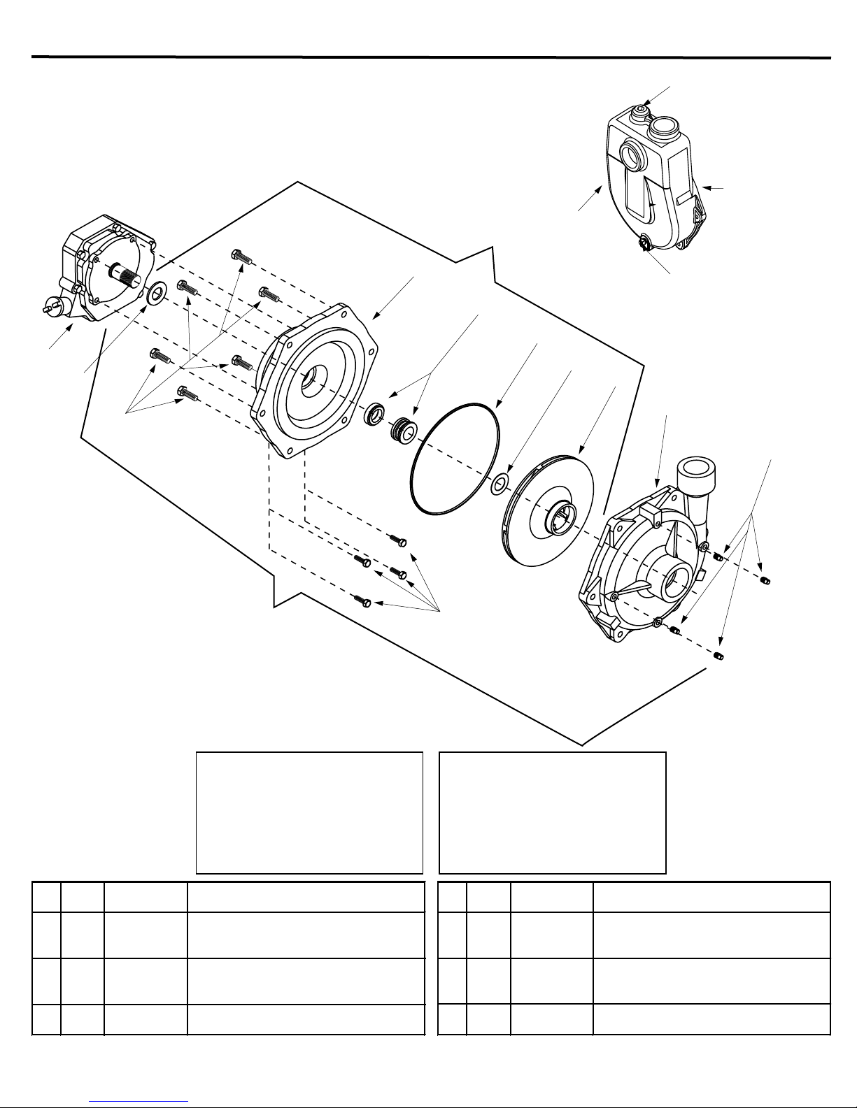
Ref. Qnty.
Ref. Qnty.
No. Req'd. Part No. Description
No. Req'd. Part No. Description
1 4 2406-0007 Drain Plug 9 1 1410-0091 Slinger Ring
2 1 0153-9200C Pump Casing (Includes SS wear ring) 10 6 2210-0086 Bolt
3 1 0404-9200P Impeller (Nylon) 11 4 2210-0098 Bolt
4 1 1700-0121 Gasket 12 1 2406-0034 Priming port plug (Standard)
5 1 1720-0180 O-Ring 12 1 2406-0036 Priming port plug (BSP)
6 1 2120-0034 Mechanical Seal - Viton 13 1 0152-9075C Pump Casing (Standard NPT)
7 1 0707-9200C Flange 13 1 0152-9075C1 Pump Casing (BSP)
8 1 2541-0037 Honda eng. (Model 1550) (GX-270PA)* 14 1 2406-0002 Drain plu g
Models 1550,1550-SP, 1550-BSP, 1551, 1551-SP, 1551-BSP
12
1551-SP,
1551-BSP
Self Priming
pump kit less
gas engine
7
6
5
8
9
10
4
3
14
2
13
1
1551
Pump kit less gas engine
Seal Kit for 1550 and 1551
No. 3430-0464 consists of:
(1) Ref. 4 Gasket
(1) Ref. 5 O-ring
(1) Ref. 6 Mechanical Seal
* CONTACT THE ENGINE MANUFACTURER FOR THIS PRODUCT NUMBER
11
Note: When ordering parts, give
quantity, part number, description
and complete model number.
Reference numbers are used
ONLY to identify parts in the
drawing and NOT to be used
as order numbers.
Form 300AG-13 9-03
Page 33
mm
A
B
C
D
EFGHI
JKL
M
N
Dimensions
Inches
mm
A
B
CDEFGHI
JKL
Dimensions
Inches
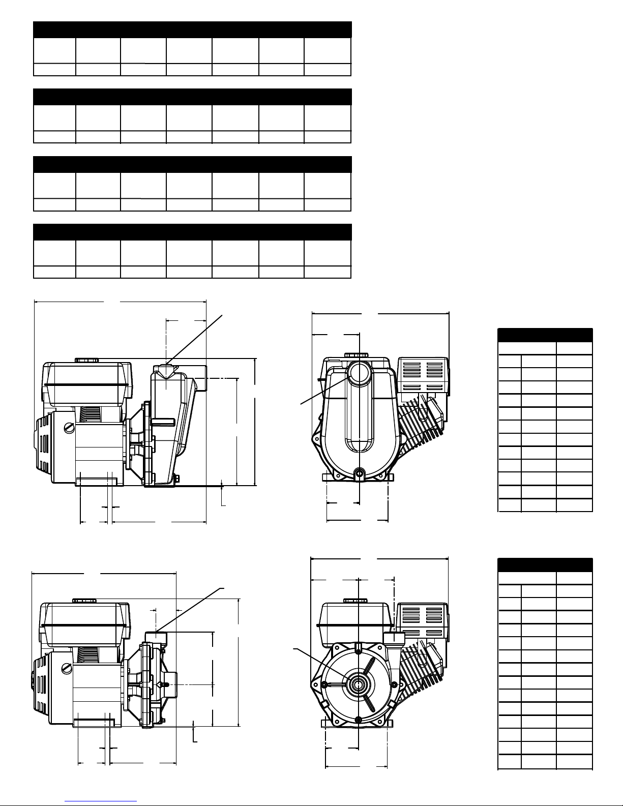
1550 Based on 9.0 HP Honda
GPM at
20 PSI
145
GPM at
40 PSI
130
GPM at
60 PSI
107
GPM at
80 PSI
87
GPM at
100 PSI
69
English Standard
GPM at
120 PSI
45
GPM at
140 PSI
16
1550 Based on 9.0 HP Honda
LPM at
1.4 BAR
549
LPM at
2.8 BAR
492
LPM at
4.1 BAR
405
LPM at
5.5 BAR
329
1550SP Based on 9.0 HP Honda
GPM at
10 PSI
145
GPM at
20 PSI
141
GPM at
40 PSI
118
GPM at
60 PSI
93
1550SP Based on 9.0 HP Honda
LPM at
0.7 BAR
549
LPM at
1.4 BAR
534
LPM at
2.1 BAR
447
LPM at
2.8 BAR
352
A
H
C
B
D
LPM at
6.9 BAR
261
GPM at
80 PSI
71
LPM at
3.4 BAR
269
2" NPT
OUTLET
F
E
LPM at
8.3 BAR
GPM at
100 PSI
LPM at
4.1 BAR
G
2" NPT
INLET
LPM at
9.7 BAR
170
English Standard
GPM at
120 PSI
49
LPM at
4.8 BAR
185
106
Metric
61
28
Metric
J
K
I
1550SP
21.69
3.41
0.59
11.87
0.13
13.56
16.05
5.06
17.30
6.00
4.14
7.75
550.9
86.6
15.0
301.5
3.3
344.4
407.7
128.5
65.0
152.4
105.2
196.9
L
A
I
G
F
E
C
B
D
1-1/2" NPT
OUTLET
H
2" NPT
INLET
K
J
1550
N
18.16
16.05
17.30
L
M
3.41
0.59
8.34
0.13
5.25
6.63
2.56
6.00
4.14
7.75
4.50
461.3
86.6
15.0
211.8
3.3
133.4
168.4
407.7
65.0
439.4
152.4
105.2
196.9
114.3
Page 34
Limited Warranty on Hypro Pumps and Other Hypro Products
Hypro warrants to the original purchaser of its products (the “Purchaser”) that such products will be free
from defects in material and workmanship under normal use for the period of one (1) year for all products except: oil crankcase
plunger pumps will be free from defects in material and workmanship under normal use for the period of five (5) years, and
accessories will be free from defects in material and workmanship under normal use for the period of ninety (90) days. In addition,
Hypro warrants to the purchaser all forged brass pump manifolds will be free from defects in material and workmanship under
normal use and from damage resulting from environmental conditions for the life of the pump.
“Normal use” does not include use in excess of recommended maximum speeds, pressures, vacuums and temperatures, or use
requiring handling of fluids not compatible with component materials, as noted in Hypro product catalogs, technical literature, and
instructions. This warranty does not cover freight damage, freezing damage, normal wear and tear, or damage caused by
misapplication, fault, negligence, alterations, or repair that affects the performance or reliability of the product.
THIS WARRANTY IS EXCLUSIVE. HYPRO MAKES NO OTHER WARRANTY, EXPRESS OR IMPLIED, INCLUDING BUT NOT
LIMITED TO ANY WARRANTY OF MERCHANTABILITY OR FITNESS FOR A PARTICULAR PURPOSE.
Hypro’s obligation under this warranty is, at Hypro’s option, to either repair or replace the product upon return of the entire product
to the Hypro factory in accordance with the return procedures set forth below. THIS IS THE EXCLUSIVE REMEDY FOR ANY
BREACH OF WARRANTY.
IN NO EVENT SHALL HYPRO BE LIABLE FOR ANY INCIDENTAL OR CONSEQUENTIAL DAMAGES OF ANY KIND,
WHETHER FOR BREACH OF ANY WARRANTY, FOR NEGLIGENCE, ON THE BASIS OF STRICT LIABILITY, OR
OTHERWISE.
Return Procedures
All pumps or products must be flushed of any chemical (ref. OSHA Section 0910.1200 (d)(e)(f)(g)(h)) and hazardous
chemicals must be labeled before being shipped* to Hypro for service or warranty consideration. Hypro reserves the right
to request a Material Safety Data sheet from the Purchaser for any pump or product Hypro deems necessary. Hypro reserves the
right to “disposition as scrap” pumps or products returned which contain unknown substances, or to charge for any and all costs
incurred for chemical testing and proper disposal of components containing unknown substances. Hypro requests this in order to
protect the environment and personnel from the hazards of handling unknown substances.
For technical or application assistance, call the Hypro Technical/Application number: 1-800-445-8360.
To obtain service or warranty assistance, call the Hypro Service and Warranty number: 1-800-468-3428;
or call the Hypro Service and Warranty FAX: (651) 766-6618.
Be prepared to give Hypro full details of the problem, including the following information:
1. Model number and the date and from whom you purchased your pump.
2. A brief description of the pump problem, including the following:
• Liquid pumped. State the pH and any non-soluble • Drive type (gas engine/electric motor; direct/belt drive;
materials, and give the generic or trade name. tractor PTO) and rpm of pump.
• Temperature of the liquid and ambient environment. • Viscosity (of oil, or other than water weight liquid).
• Suction lift or vacuum (measured at the pump). • Elevation from the pump to the discharge point.
• Discharge pressure. • Size and material of suction and discharge line.
• Size, type, and mesh of the suction strainer. • Type of spray gun, orifice size, unloader/relief valve.
Hypro may request additional information, and may require a sketch to illustrate the problem. Contact the factory to receive a
return material authorization before sending the product. All pumps returned for warranty work should be sent shipping charges
prepaid to: HYPRO
Attention: Service Department
375 Fifth Avenue NW
New Brighton, Minnesota 55112-3288
* Carriers, including U.S.P.S., airlines, UPS, ground freight, etc., require specific identification of any hazardous materials being shipped.
Failure to do so may result in a substantial fine and/or prison term. Check with your shipping company for specific instructions.
Note: This warranty does not apply to Hypro Pump Kit Model 1538,
1551, 1538-SP and 1551-SP. This is because the user could incorrectly
assemble the parts and cause the pump to work improperly.
Hypro 2004
Printed in USA
 Loading...