

Page 1

Hyper Vision
DVR-800 & 1600
8 & 16 Channels DVR
Card Kit Installation Guide
Date: Apr. 17. 2003
1
Page 2

LIST
1. DVR-800 & 1600 DVR SYSTEM REQUIREMENT.................................................................3
2. DVR-800 & 1600 CARD KIT PACKAGE CONTENTS...........................................................4
3. INST ALL THE CAPTURE CARDS ...........................................................................................5
4. INSTALL THE FLASH MODULE & HARD DISK.................................................................6
4-1 INSTALL THE FLASH MODULE ......................................................................................................6
4-2 INST ALL HARD DISK.....................................................................................................................7
5. INSTALL OTHER PARTS..........................................................................................................8
5-1 CPU.......................................................................................................................................8
5-2 DRAM...................................................................................................................................8
5-3 FLOPPY ..................................................................................................................................8
5-4 RESET BUTTON ON CASE........................................................................................................8
6. CONFIGURE BIOS PARAMETERS...............................................................................................9
6-1. FOR GIGABYTE GA-8IEX............................................................................................................10
6-2.FOR GIGABYTE GA-8SG667........................................................................................................12
6-3.FOR ASUS P4S533-E...................................................................................................................14
6-4.FOR ASUS P4PE ..........................................................................................................................17
6-5.FOR GIGABYTE GA-8PE667 PRO.................................................................................................21
7. BOOT AND TEST............................................................................................................................24
7-1 CONNECT CAMERAS ..................................................................................................................24
7-2 BOOT AND TEST .........................................................................................................................24
8. QUESTION AND ANSWER ...........................................................................................................25
8-1 SYSTEM REQUESTS TO FORMAT HARD DISK AGAIN AFTER FORMA TTING HARD DISK...................25
8-2 SYSTEM REBOOTS CONTINUOUSLY. ............................................................................................25
2
Page 3

1. DVR-800 & 1600 DVR System Requirement
Hyper Vision 8CH & 16CH DVR card kit needs to specify the combination of
“motherboard chipset ”, “VGA chip”, and “network interface chip”.
Hyper Vision DVR card kit specifies:
Motherboard Chipset Intel 845E, SiS645DX, SiS648, Intel 845PE
VGA Chip nVIDIA TNT2, GeForce2, GeForce4
Network Interface Chip Realtek 8139C
Remark: DVR-800 & 1600 also supports VGA card with TV-out function. If you
would like to install the VGA card with TV-out function, you could use the
VGA card with nVidia GeForce4 MX440 chip (eg. MSI MX440-T8X).
This document takes GigaByte GA-8IEX motherboard (Intel 845E chipset) as
an example, which has the following peripheral controllers:
GA-8IEX
Motherboard Chipset Intel 845E
VGA Chip nVIDIA TNT2
Network Interface Chip Realtek 8139C
If you could not find GigaByte GA-8IEX motherboard, you could try the other
motherboards such as Gigabyte GA-8SG667, GA-8PE667 Pro, ASUS P4S533-E,
ASUS P4PE, or motherboards with Intel 845E/ Intel 845PE/ SiS645DX/ SiS648
chipset.
3
Page 4
2. DVR-800 & 1600 Card Kit Package Contents
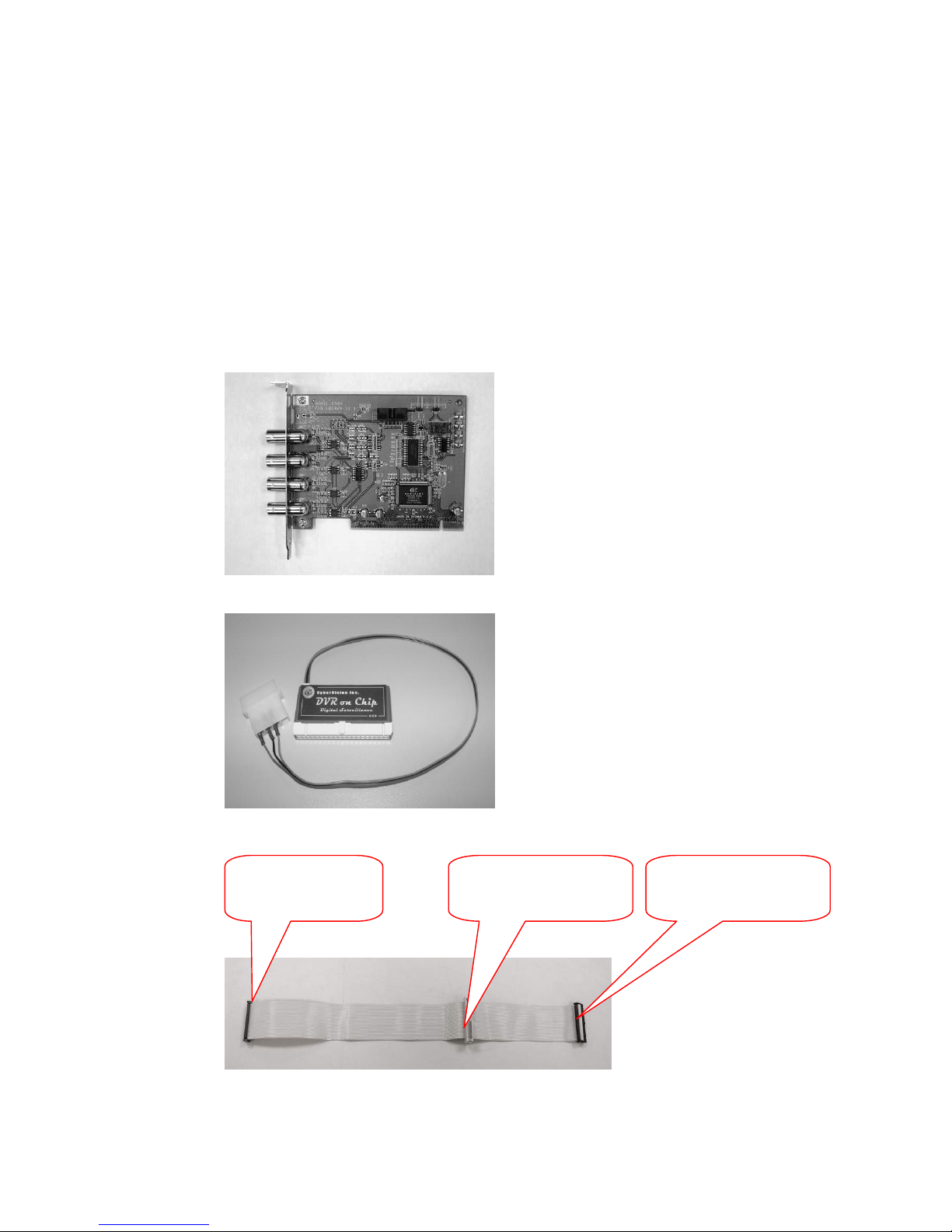
DVR-800 & 1600 card kit includes,
1. Four capture cards (Fig.2-1).
2. One system module and one power cable for this module (Fig2-2)
3. One special cable for connecting the system module and internal CD/RW. If you
use the external CD/RW (USB interface), you won’t need this cable (Fig2-3).
Fig.2-1 Capture Card
Fig.2-2 System Module
Fig.2-3 Special Cable
Plug into the
primary IDE slot
Connect to system
module
Connect to
internal CD/RW
4
Page 5

Install the Capture Cards
This section describes the installation procedures on GigaByte GA-8IEX
motherboard (w/ Intel 845E chipset) as an example.
Please install all interface cards as the photo (Fig 3-1) below:
1. Insert the display card into the AGP slot.
2. Insert 4 capture cards into 1st, 2nd, 3rd, 4th PCI slots.
3. Insert the network interface card into the last PCI slot.
4 capture cards
here
AGP slot for
display card
Network card
here
Fig 3-1 DVR-800 & 1600 capture cards installed on GA-8IEX
Remark:
The example above is the installation procedure on GA-8IEX motherboard. For
the other motherboard with Intel 845E/SiS 645DX/SiS648 chipset, the
installation procedure is similar to the above procedures.
5
Page 6
3. Install the Flash Module & Hard Disk
4-1 Install the Flash Module
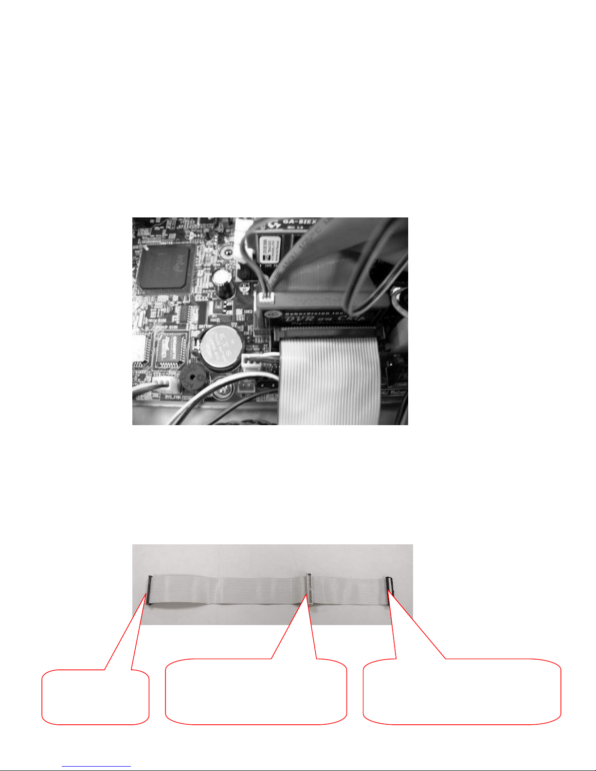
In general, there are two IDE slots, one is Primary (the red one on GA-8IEX),
and the other is Secondary. Please plug the System Module into Primary IDE slot and
set it as “Master”, then connect the D-type power line to power supply as the figure
below.
If you would like to install the internal CD/RW burner also (DVR-800 & 1600
supports the internal CD/RW and USB external CD/RW both), please use the special
cable as the figure below which is included in the shipping box to connect the system
module (set as Primary IDE Master) and the internal CD/RW (set as Primary IDE
Slave).
6
Connect to internal CD/RW burner
(Set as Primary IDE “Slave”)
Plug into the
primary IDE slot
Connect to system module
(Set as Primary IDE “Master”)
Page 7

4-2 Install Hard disk
DVR-800 & 1600 could support 2 Hard Disks. If you install one hard disk only,
please set it as Secondary IDE “Master”. If you install the 2nd hard disk, please set it
as Secondary IDE “Slave”.
First, configure the jumper of hard disk as Master (refer to manual of hard disk),
then link hard disk with 40-pins parallel cable to the Secondary IDE slot (the white
one on the GA-8IEX).
Please pay attention to the direction of the 40-pins parallel cable. Some cheap
cable without “foolproof” may cause mistake. Normally, there is a red line marked on
the 1
st
pin of the cable, which should be connected to 1st pin of hard disk and IDE slot.
7
Page 8

5. Install Other Parts
5-1 CPU
GA-8IEX has a Socket 478 for CPU. For Hyper Vision, the system recording
frame rate is depended on the CPU that system uses. If it uses the Intel P4-2.4G, the
system recording frame rate is around 100fps(Frame per Second).
5-2 DRAM
System’s minimum requirement is 256MB(DDR for GA-8IEX).
5-3 Floppy
Hyper Vision supports “Save-to-Floppy” function for single picture, so you can
connect a 3.5” 1.44MB floppy to FDD slot on motherboard for this feature.
5-4 Reset Button on Case
Please DO NOT attach the Reset Button to the reset pin of motherboard, which
means, please do not enable reset function.
If users make the mistake to trigger the reset button, it will immediately
shutdown the whole machine abnormally and loose some records. However, if user
push the “Power Button”, the system could close all the opened files, and keep the
integrity of records.
8
Page 9

6. Configure BIOS Parameters
Due to heavy traffic between IO devices and motherboard, the optimum BIOS
configuration is necessary for Digital Video Recorder system to have stable operation.
When you finish assembling Capture Cards, Flash Module, and Hard Disk,
please connect the keyboard and mouse before turning on power for setting BIOS.
After power on, you will see a flash screen of display logo followed by a POST
(power on self-test) screen with sentence “Hit DEL if you want to run SETUP”.
Press DEL to enter BIOS setup menu.
There are only few keys used in this setting: Direction keys are used to select
entities of functions. [Page Up], [Page Down], and [Tab] are used to switch options of
function.
You can select [Load Optimize Default] in the main menu to load optimum
setting, then please refer to the setting listed in the next section.
9
Page 10

6-1. for Gigabyte GA-8IEX
Please select [Load Optimize Defaults] in the main menu to load optimum
setting, then please refer to the setting listed in the next.
[Standard CMOS features]
IDE Primary Master [PQI IDE Secured Disk]
IDE Primary Slave [None]
IDE Secondary Master [your hard disk]
IDE Secondary Slave [None]
Drive A [1.44M, 3.5“]
Drive B [None]
Floppy 3 Mode Support [Disabled]
Halt on [All, But Keyboard]
[Advanced BIOS Features]
First Boot Device [HDD-0]
Second Boot Device [Disabled]
Third Boot Device [Disabled]
Boot Up Floppy Seek [Disabled]
Init Display First [AGP]
[Integrated Peripherals]
On Chip Primary Master PCI IDE [Enabled]
On Chip Secondary Slave PCI IDE [Enabled]
IDE1 Conductor Cable [Auto]
IDE2 Conductor Cable [Auto]
USB Controller [Enabled]
USB Keyboard Support
[Disabled]
USB Mouse Support [Disabled]
AC97 Audio [Disabled]
Onboard Lan Controller [Disabled]
Onboard Lan Boot Rom [Disabled]
Onboard Serial Port 1 [3F8/IRQ4](Enable for Modem)
Onboard Serial Port 2 [Disabled] (Enable for PTZ)
10
Page 11

Onboard Parallel Port [Disabled]
Game Port Address [Disabled]
Midi Port Address [Disabled]
CIR Port Address [Disabled]
[Power Management Setup]
ACPI Suspend Type [S1(POS)]
Soft-off by PWR-BTTN [Instant-Off]
PME Event Wake Up [Enabled]
ModemRingOn/WakeOnLan [Disabled]
Resume by Alarm [Disabled ]
Power On By Mouse [Disabled]
Power On By Keyboard [Disabled]
AC BACK Function [Memory]
[PnP/PCI Configurations]
PCI1/PCI5 IRQ Assignment [Auto]
PCI2/PCI6 IRQ Assignment [Auto]
PCI3 IRQ Assignment [Auto]
PCI4 IRQ Assignment [Auto]
[PC Health Status]
Reset Case Open Status [Disabled]
CPU Warning Temperature [Disabled]
CPU FAN Fail Warning [Disabled]
Power FAN Fail Warning [Disabled]
System FAN Fail Warning [Disabled]
[Frequency/Voltage Control]
CPU Host Clock Control [Disabled]
Host/DRAM Clock Ratio [Auto]
DIMM OverVoltage Control [Normal]
AGP OverVoltage Control [Normal]
CPU Voltage Control [Normal]
11
Page 12

6-2.for Gigabyte GA-8SG667
Please select [Load Optimize Defaults] in the main menu to load optimum
setting, then please refer to the setting listed in the next.
[Standard CMOS features]
IDE Primary Master [PQI IDE Secured Disk]
IDE Primary Slave [None]
IDE Secondary Master [your hard disk]
IDE Secondary Slave [None]
Drive A [1.44M, 3.5“]
Drive B [None]
Floppy 3 Mode Support [Disabled]
Halt on [All, But Keyboard]
[Advanced BIOS Features]
First Boot Device [HDD-0]
Second Boot Device [Disabled]
Third Boot Device [Disabled]
Boot Up Floppy Seek [Disabled]
Password Check [Setup]
Init Display First [AGP]
[Integrated Peripherals]
IDE1 Conductor Cable [Auto]
IDE2 Conductor Cable [Auto]
On Chip Primary PCI IDE [Enabled]
On Chip Secondary PCI IDE [Enabled]
AC97 Audio [Disabled]
USB Controller [Enabled]
USB Legacy Support
[Disabled]
Onboard Serial Port 1 [3F8/IRQ4](Enable for modem)
Onboard Serial Port 2 [2F8/IRQ3](Enable for PTZ)
Onboard Parallel Port [Disabled]
Game Port Address [Disabled]
12
Page 13

Midi Port Address [Disabled]
[Power Management Setup]
ACPI Suspend Type [S1(POS)]
Soft-off by PWR-BTTN [Off]
System After AC Back [Laststate]
IRQ [3-7,9-15]NMI [Enabled]
ModemRingOn/WakeOnLan [Enabled]
PME Event Wake Up [Enabled]
Power On By Keyboard [Disabled]
Power On By Mouse [Disabled]
Resume by Alarm [Disabled ]
Power LED in S1 State [Blinking]
[PnP/PCI Configurations]
PCI 4 IRQ Assignment [Auto]
PCI 1 IRQ Assignment [Auto]
PCI 2 IRQ Assignment [Auto]
PCI 3 IRQ Assignment [Auto]
[PC Health Status]
Reset Case Open Status [Disabled]
CPU FAN Fail Warning [Disabled]
System FAN Fail Warning [Disabled]
[Frequency/Voltage Control]
Linear Frequency Control [Disabled]
AGP/PCI Clock Control [Auto]
13
Page 14

6-3.for ASUS P4S533-E
Please select [Load Optimize Defaults] in the main menu to load optimum
setting, then please refer to the setting listed in the next.
[Main]
Legacy Diskette A [1.44M, 3.5“]
Floppy 3 Mode Support [Disabled]
Primary Master [PQI IDE Secured Disk]
Type [Auto]
Cylinders [500 ]
Head [8 ]
Sector [16 ]
Multi-sector Transfer [Maximum]
Smart Monitor [Disabled]
PIO Mode [ 2 ]
ULTRA DMA Mode [Disabled]
Primary Slave [Auto]
Boot Up Numlock Status [On]
Keyboard Auto Repeat Rate [12 /Sec]
Keyboard Auto Repeat Delay [1/4 Sec]
Secondary Master [your hard disk]
Secondary Slave [Auto]
Language [English(US)]
Supervisor Password [Disabled]
User Password [Disabled]
Halt on [All but Disk/Keyboard]
[Advanced ]
CPU Speed [1700MHz]
CPU Frequency Multiple [17x]
CPU External Frequency(MHz) [100/33]
Memory Frequency [Auto]
CPU Vcore set [Auto]
CPU Vcore [1.750B]
CPU Level 2 Cache [Enabled]
14
Page 15

BIOS Update [Disabled]
PS/2 Mouse function Control [Enabled]
USB Legacy Support [Auto]
OS/2 Onboard Memory >64M [Disabled]
Chip Configuration
SDRAM Configuration [By SPD]
SDRAM CAS Latency [2.5T]
SDRAM RAS to CAS Delay [3T]
SDRAM RAS Precharge Time [3T]
SDRAM RAS Active Time [7T]
SDRAM Commend Lead-off Time [Auto]
Graphic Aperture Size [64M]
AGP Capability [4xMode]
AGP Fast Write Capability [Enabled]
Video Memory Cached Mode [UC]
Memory Hole at 15M-16M [Disabled]
PCI 2.1 Support [Enabled]
Onboard PCI IDE Enable [Both]
IDE Bus Mater Support [Enabled]
I/O Device Configuration
Floppy Disk Access [R/W]
Onboard Serial Port 1 [3F8H/IRQ4]
Onboard Serial Port 2 [2F8H/IRQ3]
UART2 Use As [COM Port]
Onboard Parallel Port [Disabled]
Speech POST Reporter [Disabled]
PCI Configuration
Slot 1/5 IRQ [Auto]
Slot 2/6 IRQ [Auto]
Slot 3 IRQ [Auto]
Slot 4 IRQ [Auto]
PCI/VGA Palette Snoop [Disabled]
PCI Latency Timer [32]
Primary VGA BIOS [AGP VGA Card]
USB Function [Enabled]
USB 2.0 Function [Enabled]
Onboard PCI Audio Controller [Disabled]
PCI IRQ Resource Exclusion
15
Page 16

IRQ 3 Reserved [No/ICU]
IRQ 4 Reserved [No/ICU]
IRQ 5 Reserved [No/ICU]
IRQ 7 Reserved [No/ICU]
IRQ 9 Reserved [No/ICU]
IRQ 10 Reserved [No/ICU]
IRQ 11 Reserved [No/ICU]
IRQ 12 Reserved [No/ICU]
IRQ 14 Reserved [No/ICU]
IRQ 15 Reserved [No/ICU]
[Power]
Power Management [User Defined]
Video Off Option [Suspend-> Off]
Video Off Method [DPMS Off]
HDD Power Down [Disabled]
ACPI Suspend to RAM [Disabled]
Suspend Mode [Disabled]
PWR Button < 4 Secs [Soft Off]
Power Up Control
AC Power Loss Restart [Previous State]
Wake/Power Up On Ext. Mode [Disabled]
Power Up On PCI Device [Disabled]
Power Up BY PS/2 Keyboard [Disabled]
Automatic Power Up [Disabled]
Hardware Monitor
Q Fan Function Control [Disabled]
[Boot]
1. IDE Hard Driver [PQI IDE Secured Disk]
2. Removable Deice [Disabled]
3.ATAPI CD-ROM [Disabled]
4.Other Boot Device [Disabled]
Plug & Play O/S [No]
Boot Virus Detection [Disabled]
Quick Power on Self Test [Enabled]
16
Page 17

Boot Up Floppy Seek [Disabled]
Full Screen Logo [Disabled]
Interrupt Mode [APIC]
6-4.for ASUS P4PE
Please select [Load Optimize Defaults] in the main menu to load optimum
setting, then please refer to the setting listed in the next.
[Main]
Legacy Diskette A [1.44M, 3.5“]
Floppy 3 Mode Support [Disabled]
Primary Master [PQI IDE Secured Disk]
Type [Auto]
Cylinders [500 ]
Head [8 ]
Sector [16 ]
Multi-sector Transfer [Maximum]
Smart Monitor [Disabled]
PIO Mode [ 2 ]
ULTRA DMA Mode [Disabled]
Primary Slave [Auto]
Boot Up Numlock Status [On]
Keyboard Auto Repeat Rate [12 /Sec]
Keyboard Auto Repeat Delay [1/4 Sec]
Secondary Master [your hard disk]
Type [Auto]
Cylinders [1024 ]
Head [16 ]
Sector [63 ]
Multi-sector Transfer [Maximum]
Smart Monitor [Disabled]
PIO Mode [ 4 ]
ULTRA DMA Mode [5]
Secondary Slave [Auto]
Keyboard Features
Boot Up Numlock Status [Off]
17
Page 18

Keyboard Auto-Repeat Rate [ 12/Sec ]
Keyboard Auto-Repeat Delay [1/4 Sec ]
Language [English(US)]
Supervisor Password [Disabled]
User Password [Disabled]
Halt on [All but Disk/Keyboard]
[Advanced ]
CPU Speed [2400MHz]
CPU Frequency Multiple [18x]
CPU External Frequency(MHz) [133]
Memory Frequency [Auto]
AGP/PCI Frequency Setting [Auto]
CPU Vcore Setting [Auto]
CPU Vcore [1.500V]
DDR Reference Voltage [Auto]
AGP VDDQ Voltage [Auto]
CPU Level 1 Cache [Enabled]
CPU Level 2 Cache [Enabled]
BIOS Update [Enabled]
PS/2 Mouse function Control [Auto]
USB Legacy Support [Auto]
OS/2 Onboard Memory >64M [Disabled]
Chip Configuration
SDRAM Configuration [By SPD]
SDRAM CAS Latency [2.5T]
SDRAM RAS to CAS Delay [3T]
SDRAM RAS Precharge Time [3T]
SDRAM Active Precharge Delay [7T]
System Performance Mode [Auto]
SDRAM Idle Timer [Auto]
SDRAM Burst Length [Auto]
Memory Turbo Mode [Disabled]
DRAM Refresh Rate [By SPD]
Graphic Aperture Size [64MB]
AGP Capability [4x Mode]
Video Memory Cache Mode [UC]
18
Page 19

Memory Hole At 15M-16M [Disabled]
Delay Transaction [Enabled]
Onboard PCI IDE Enable [Both]
USB 2.0 HS Reference Voltage [Medium]
I/O Device Configuration
Floppy Disk Access Control [R/W]
Onboard Serial Port 1 [3F8H/IRQ4]
Onboard Serial Port 2 [2F8H/IRQ3]
UART2 Use As [COM Port]
Onboard Parallel Port [Disabled]
Onboard AC97 Audio Controller [Disabled]
Onboard Game Port [Disabled]
Onboard MI/DI IO [Disabled]
Speech POST Reporter [Enabled]
PCI Configuration
Slot 1/5 IRQ [Auto]
Slot 2 IRQ [Auto]
Slot 3 IRQ [Auto]
Slot 4 IRQ [Auto]
Slot 6IRQ [Auto]
PCI/VGA Palette Snoop [Disabled]
PCI Latency Timer [32]
USB 1.1 Controller [3 Controller]
USB 2.0 Controller [Enabled]
Primary VGA BIOS [AGP VGA Card]
Onboard LAN Controller [Disabled] =>As our
systems don’t support BroadCom net chip, please insert extra
Realtek8139 Lan Card
Onboard LAN Boot ROM [Disabled]
PCI IRQ Resource Exclusion
IRQ 3 Reserved [No/ICU]
IRQ 4 Reserved [No/ICU]
IRQ 5 Reserved [No/ICU]
IRQ 7 Reserved [No/ICU]
IRQ 9 Reserved [No/ICU]
IRQ 10 Reserved [No/ICU]
IRQ 11 Reserved [No/ICU]
IRQ 12 Reserved [No/ICU]
19
Page 20

IRQ 14 Reserved [No/ICU]
IRQ 15 Reserved [No/ICU]
[Power]
Power Management [User Defined]
Video Off Option [Suspend-> Off]
Video Off Method [DPMS Off]
HDD Power Down [Disabled]
ACPI Suspend to RAM [Disabled]
Suspend Mode [Disabled]
PWR Button < 4 Secs [Soft Off]
Power Up Control
AC Power Loss Restart [Previous State]
Wake/Power Up On Ext. Mode [Disabled]
Power Up On PCI Device [Disabled]
Power Up BY PS/2 Keyboard [Disabled]
Power Up BY PS/2 Mouse [Diabled]
Automatic Power Up [Disabled]
Hardware Monitor
Q Fan Function Control [Disabled]
[Boot]
1. Removable Deice [Disabled]
2. IDE Hard Driver [PQI IDE Secured Disk]
3.ATAPI CD-ROM [None]
4.Other Boot Device [Disabled]
Plug & Play O/S [No]
Reset Configuration Data [No]
Boot Virus Detection [Enabled]
Quick Power on Self Test [Enabled]
Boot Up Floppy Seek [Enabled]
Full Screen Logo [Disabled]
Interrupt Mode [APIC]
20
Page 21

6-5.for Gigabyte GA-8PE667 Pro
Please select [Load Optimize Defaults] in the main menu to load optimum
setting, then please refer to the setting listed in the next.
[Standard CMOS features]
IDE Primary Master [PQI IDE Secured Disk]
IDE Primary Slave [None]
IDE Secondary Master [your hard disk]
IDE Secondary Slave [None]
Drive A [1.44M, 3.5“]
Drive B [None]
Floppy 3 Mode Support [Disabled]
Halt on [All, But Keyboard]
[Advanced BIOS Features]
First Boot Device [HDD-0]
Second Boot Device [Disabled]
Third Boot Device [Disabled]
Boot Up Floppy Seek [Disabled]
Password Check [Setup]
Init Display First [AGP]
[Integrated Peripherals]
On Chip Primary PCI IDE [Enabled]
On Chip Secondary PCI IDE [Enabled]
IDE1 Conductor Cable [Auto]
IDE2 Conductor Cable [Auto]
USB Controller [Enabled]
USB Keyboard Support
[Disabled]
USB Mouse Support [Disabled]
AC97 Audio [Disabled]
Onboard H/W LAN [Enabled]
Onboard LAN Boot ROM [Disabled]
Onboard Serial Port 1 [3F8/IRQ4](Enable for modem)
21
Page 22

Onboard Serial Port 2 [2F8/IRQ3](Enable for PTZ)
Onboard Parallel Port [Disabled]
Game Port Address [Disabled]
Midi Port Address [Disabled]
CIR Port Address [Disabled]
[Power Management Setup]
ACPI Suspend Type [S1(POS)]
Power LED in S1 State [Blinking]
Soft-off by PWR-BTTN [Off]
PME Event Wake Up [Enabled]
ModemRingOn/WakeOnLan [Enabled]
Resume by Alarm [Disabled ]
Power On By Mouse [Disabled]
Power On By Keyboard [Disabled]
AC Back Function [Laststate]
[PnP/PCI Configurations]
PCI1/PCI5 IRQ Assignment [Auto]
PCI2/PCI6 IRQ Assignment [Auto]
PCI 3 IRQ Assignment [Auto]
PCI 4 IRQ Assignment [Auto]
[PC Health Status]
Reset Case Open Status [Disabled]
CPU Warning Temperature [Disabled]
CPU FAN Fail Warning [Disabled]
Power Fan Fair Warning [Disabled]
System FAN Fail Warning [Disabled]
[Frequency/Voltage Control]
CPU Host Clock Control [Disabled]
Host/DRAM Clock Ratio [Auto]
DIMM OverVoltage Control [Normal]
22
Page 23

AGP OverVoltage Control [Normal]
CPU Voltage Control [Normal]
23
Page 24
7. Boot and Test
7-1 Connect Cameras
Please put cameras at fix positions, then finish adjusting and calibrating.
Connect cameras to Capture Cards with 5C2V coaxial cables. Capture Cards use BNC
female connector. If your cameras only have F connector, you need to buy the
“BNC to F” adapters.
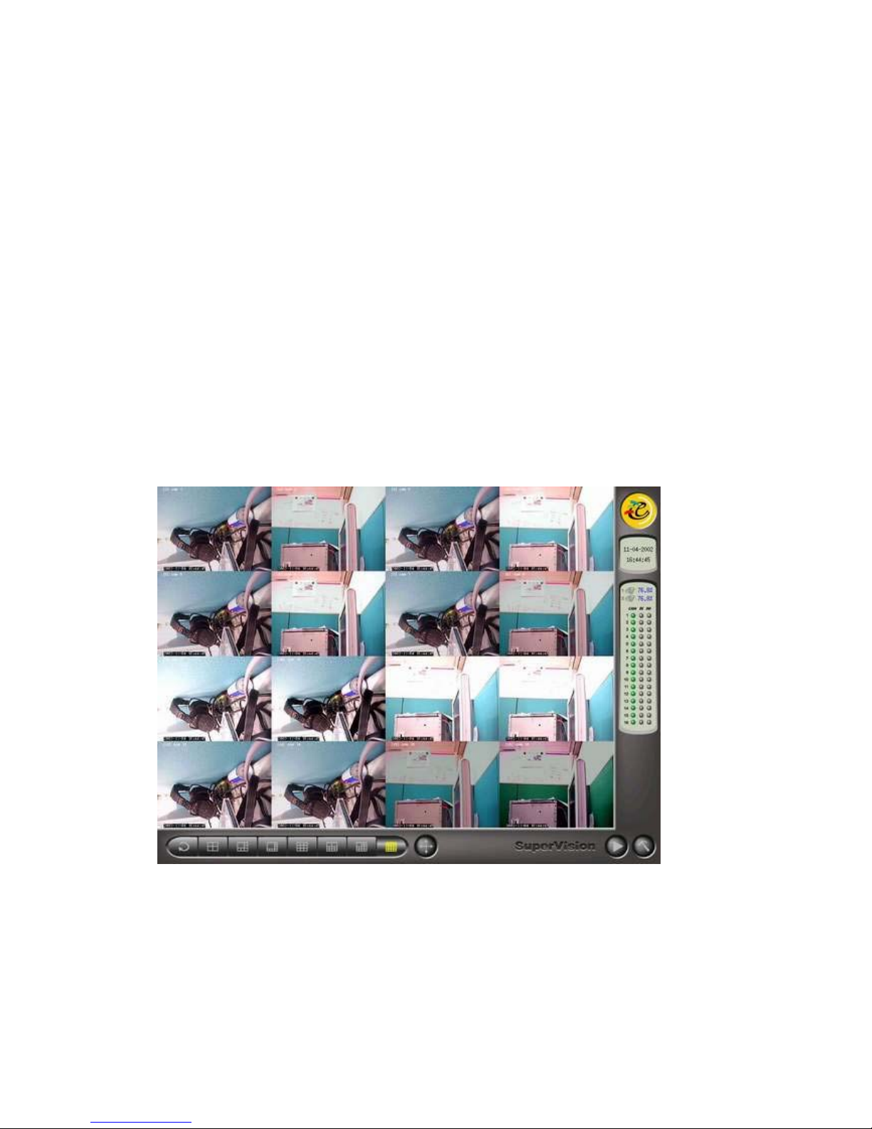
7-2 Boot and Test
When first booting, system will enter the “Disk Management” option. Please
refer to the Section 4 of the Hyper Vision 16 user manual for the related procedures
for the hard disk management. After finishing the disk management, the system will
reboot and show the main monitoring screen as follows.
After rebooting, if DVR does not appear this GUI (Graphical User Interface),
and show out the text: “Hyper Vision Login: “, it means your display card doesn’t
match, please check the Chapter 1 for the right display card again.
24
Page 25

8. Question and Answer
8-1 System requests to format Hard disk again after
formatting hard disk.
Ans: Hard disk failure.
Ans: IDE flat cable failure or with wrong connection.
8-2 System reboots continuously.
Ans: There might be the serious bad track on the hard disk. Please change a
new one
Ans: There are too many bad bits on the DRAM module. Please change a
new one.
25
 Loading...