

Page 1

Phoenix™ Software Version 9 Series
Installation and Setup Manual
806410 | Revision 11 | English
Page 2

© 2014 Hypertherm, Inc.
ArcGlide, COMMAND, EDGE Pro, EDGE Pro Ti, HPR, HSD, HyIntensity Fiber Laser, Hypernest, Hypernet, Hypertherm,
HyPrecision, MAXPRO, MicroEDGE Pro, Phoenix, Powermax, and Sensor are trademarks of Hypertherm, Inc. and may be registered
in the United States and other countries.
Microsoft, the Microsoft logo, and Windows are registered trademarks of Microsoft Corporation.
Other trademarks are the property of their respective owners.
Page 3

Phoenix Software® Version 9 Series
Installation and Setup Manual
806410
Revision 11
English
December 2014
Hypertherm Inc.
Hanover, NH 03755 USA
Page 4

Hypertherm Inc.
Etna Road, P.O. Box 5010
Hanover, NH 03755 USA
603-643-3441 Tel (Main Office)
603-643-5352 Fax (All Departments)
info@hypertherm.com (Main Office Email)
800-643-9878 Tel (Technical Service)
technical.service@hypertherm.com (Technical Service Email)
800-737-2978 Tel (Customer Service)
customer.service@hypertherm.com (Customer Service Email)
866-643-7711 Tel (Return Materials Authorization)
877-371-2876 Fax (Return Materials Authorization)
return.materials@hypertherm.com (RMA email)
Hypertherm Plasmatechnik GmbH
Technologiepark Hanau
Rodenbacher Chaussee 6
D-63457 Hanau-Wolfgang, Deutschland
49 6181 58 2100 Tel
49 6181 58 2134 Fax
49 6181 58 2123 (Technical Service)
Hypertherm (S) Pte Ltd.
82 Genting Lane
Media Centre
Annexe Block #A01-01
Singapore 349567, Republic of Singapore
65 6841 2489 Tel
65 6841 2490 Fax
65 6841 2489 (Technical Service)
Hypertherm (Shanghai) Trading Co., Ltd.
Unit 301, South Building
495 ShangZhong Road
Shanghai, 200231
PR China
86-21-60740003 Tel
86-21-60740393 Fax
Hypertherm Europe B.V.
Vaartveld 9
4704 SE
Roosendaal, Nederland
31 165 596907 Tel
31 165 596901 Fax
31 165 596908 Tel (Marketing)
31 165 596900 Tel (Technical Service)
00 800 4973 7843 Tel (Technical Service)
Hypertherm Japan Ltd.
Level 9, Edobori Center Building
2-1-1 Edobori, Nishi-ku
Osaka 550-0002 Japan
81 6 6225 1183 Tel
81 6 6225 1184 Fax
Hypertherm Brasil Ltda.
Rua Bras Cubas, 231 – Jardim Maia
Guarulhos, SP - Brasil
CEP 07115-030
55 11 2409 2636 Tel
55 11 2408 0462 Fax
Hypertherm México, S.A. de C.V.
Avenida Toluca No. 444, Anexo 1,
Colonia Olivar de los Padres
Delegación Álvaro Obregón
México, D.F. C.P. 01780
52 55 5681 8109 Tel
52 55 5683 2127 Fax
Hypertherm Korea Branch
#3904 Centum Leaders Mark B/D,
1514 Woo-dong, Haeundae-gu, Busan
Korea, 612-889
82 51 747 0358 Tel
82 51 701 0358 Fax
Page 5

Contents
Safety ....................................................................................................................................... SC-15
Recognize safety information ...............................................................................................................................................SC-15
Follow safety instructions ......................................................................................................................................................SC-15
Electrical hazards ....................................................................................................................................................................SC-15
Electric shock can kill ............................................................................................................................................................SC-16
Cutting can cause fire or explosion ....................................................................................................................................SC-17
Fire prevention .................................................................................................................................................................SC-17
Explosion prevention ......................................................................................................................................................SC-17
Toxic fumes can cause injury or death ...............................................................................................................................SC-18
Grounding safety ....................................................................................................................................................................SC-19
Static electricity can damage circuit boards ....................................................................................................................SC-19
A plasma arc can cause injury and burns .........................................................................................................................SC-20
Compressed gas equipment safety ...................................................................................................................................SC-20
Gas cylinders can explode if damaged .............................................................................................................................SC-20
Arc rays can burn eyes and skin .........................................................................................................................................SC-21
Pacemaker and hearing aid operation ...............................................................................................................................SC-22
Noise can damage hearing ...................................................................................................................................................SC-22
A plasma arc can damage frozen pipes ............................................................................................................................SC-22
Dry dust collection information ............................................................................................................................................SC-23
Laser radiation .........................................................................................................................................................................SC-24
Additional safety information ................................................................................................................................................SC-24
Warning labels ........................................................................................................................................................................SC-25
Symbols and marks ................................................................................................................................................................SC-27
Product Stewardship ...........................................................................................................SC-29
Introduction ..............................................................................................................................................................................SC-29
National and local safety regulations ..................................................................................................................................SC-29
Certification test marks .........................................................................................................................................................SC-29
Phoenix 9.76.0 Installation and Setup Manual 806410 5
Page 6

Contents
Differences in national standards .......................................................................................................................................SC-29
Safe installation and use of shape cutting equipment ...................................................................................................SC-30
Procedures for periodic inspection and testing ..............................................................................................................SC-30
Qualification of test personnel .............................................................................................................................................SC-30
Residual current devices (RCDs) .......................................................................................................................................SC-30
Higher-level systems ..............................................................................................................................................................SC-31
Environmental Stewardship .............................................................................................. SC-33
Introduction ..............................................................................................................................................................................SC-33
National and local environmental regulations ...................................................................................................................SC-33
The RoHS directive ................................................................................................................................................................SC-33
Proper disposal of Hypertherm products ..........................................................................................................................SC-33
The WEEE directive ...............................................................................................................................................................SC-33
The REACH regulation ..........................................................................................................................................................SC-34
Proper handling and safe use of chemicals .....................................................................................................................SC-34
Fumes emission and air quality ...........................................................................................................................................SC-34
Shrink-wrap License Agreement ...................................................................................... SC-35
1 System Tools ............................................................................................................................... 37
Introduction .................................................................................................................................................................................... 37
CNC performance information .................................................................................................................................................. 39
Back up the hard drive ................................................................................................................................................................ 40
Scan Hard Disk ............................................................................................................................................................................. 41
Antivirus .......................................................................................................................................................................................... 42
Defragment hard disk .................................................................................................................................................................. 43
Launch an External Program ...................................................................................................................................................... 43
Software installed on the CNC ................................................................................................................................................. 45
Phoenix software version number ..................................................................................................................................... 45
Phoenix setup files ........................................................................................................................................................................ 46
About setup files ................................................................................................................................................................... 46
Setup files from previous versions of Phoenix ............................................................................................................... 47
Save and load the setup file ............................................................................................................................................... 47
Save a setup file without using a password ........................................................................................................... 47
Save a setup file with a different name .................................................................................................................... 47
Load a setup file ............................................................................................................................................................ 48
Save and load default settings .......................................................................................................................................... 48
Save Default.ini .............................................................................................................................................................. 48
Load Default.ini .............................................................................................................................................................. 48
Reload factory settings ........................................................................................................................................................ 49
6 Phoenix 9.76.0 Installation and Setup Manual 806410
Page 7

Contents
2 Machine Setup ............................................................................................................................ 51
Axis orientation and positive motion ......................................................................................................................................... 51
About axis assignments ............................................................................................................................................................... 55
Change the axis assignments with passwords ...................................................................................................................... 55
System axis screens ..................................................................................................................................................................... 58
Machine Setups screen ...................................................................................................................................................... 58
Transverse or Rail Axis ........................................................................................................................................................ 60
Using software travel limits ................................................................................................................................................. 63
Dual Gantry Axis .................................................................................................................................................................... 64
CBH Axis ................................................................................................................................................................................ 67
Rotate Axis ............................................................................................................................................................................. 69
Tilt Axis .................................................................................................................................................................................... 71
Transverse 2 Axis .................................................................................................................................................................. 74
Laser Mapping ............................................................................................................................................................................... 78
Setting Speeds ............................................................................................................................................................................. 79
CBH Speeds ......................................................................................................................................................................... 81
THC Speeds .......................................................................................................................................................................... 81
Tilt/Rotator Speeds .............................................................................................................................................................. 82
S-curve acceleration .................................................................................................................................................................... 82
S-curve setup ........................................................................................................................................................................ 84
Torch Height Disable ................................................................................................................................................................... 85
Configuring Ports ......................................................................................................................................................................... 87
Basic Configuration .............................................................................................................................................................. 87
Phoenix Link Configuration ................................................................................................................................................. 90
Command THC Port Designation ..................................................................................................................................... 91
RS-422 Connections to Command THC with 25-pin D-type Connector ...................................................... 91
Configuring I/O ............................................................................................................................................................................. 92
Digital Input Definitions ........................................................................................................................................................ 93
Digital Output Definitions .................................................................................................................................................... 97
THC I/O ................................................................................................................................................................................ 100
Speed Pot and Joystick Setup ................................................................................................................................................ 101
3 Torch Height Control Axis Setup ......................................................................................... 103
Sensor THC axis ......................................................................................................................................................................... 103
Initial height sense .............................................................................................................................................................. 103
Entering the slide length ................................................................................................................................................... 104
Assigning the Sensor THC to an axis and selecting an analog input .................................................................... 104
Setting speeds and acceleration .................................................................................................................................... 105
Assigning the Sensor THC as a lifter ............................................................................................................................. 106
Setting servo error tolerance and stall force tolerance .............................................................................................. 106
Phoenix 9.76.0 Installation and Setup Manual 806410 7
Page 8

Contents
Sensor THC axis screen ........................................................................................................................................................... 108
Tuning the axis with gains ................................................................................................................................................. 109
Home settings for current-type drives ........................................................................................................................... 113
Tracking Mode ..................................................................................................................................................................... 113
Sensor THC I/O points ............................................................................................................................................................. 114
Watch Window setup ............................................................................................................................................................... 115
Sensor Ti axis setup ................................................................................................................................................................... 116
Machine Setups screen .................................................................................................................................................... 116
Speeds screen .................................................................................................................................................................... 116
Sensor THC Axis screen .................................................................................................................................................. 117
Station Configuration screen ........................................................................................................................................... 117
ArcGlide THC axis ..................................................................................................................................................................... 118
Gains ..................................................................................................................................................................................... 118
Speeds .................................................................................................................................................................................. 120
Mechanical ........................................................................................................................................................................... 121
Miscellaneous ...................................................................................................................................................................... 121
4 SERCOS setup ........................................................................................................................... 123
SERCOS III support .................................................................................................................................................................. 123
Drives ..................................................................................................................................................................................... 123
Bus couplers ........................................................................................................................................................................ 123
Cabling .................................................................................................................................................................................. 124
General recommendations ............................................................................................................................................... 124
Drive I/O ................................................................................................................................................................................ 124
Inline I/O bus coupler ........................................................................................................................................................ 125
Troubleshooting tips .......................................................................................................................................................... 125
SERCOS setup screen ..................................................................................................................................................... 126
SERCOS II support ................................................................................................................................................................... 127
Drives ..................................................................................................................................................................................... 127
I/O bus couplers and I/O modules ................................................................................................................................. 127
I/O bus couplers ................................................................................................................................................................. 127
I/O modules ......................................................................................................................................................................... 128
SERCSO II setup screen .................................................................................................................................................. 129
5 Station Setup ............................................................................................................................. 131
Overview ....................................................................................................................................................................................... 131
Generic and numbered I/O ...................................................................................................................................................... 131
Generic I/O .......................................................................................................................................................................... 131
Numbered I/O ...................................................................................................................................................................... 132
8 Phoenix 9.76.0 Installation and Setup Manual 806410
Page 9

Contents
Enabling station I/O ................................................................................................................................................................... 132
Auto Select and Manual Select inputs and Station Enable LED output ................................................................ 132
Basic operating sequence ................................................................................................................................................ 133
Using manual mode as an override ................................................................................................................................ 133
Summary ............................................................................................................................................................................... 133
Station configuration screen .................................................................................................................................................... 136
Guidelines for using the Station Configuration screen ...................................................................................................... 136
Conflicting process .................................................................................................................................................................... 137
Example of a conflicting process .................................................................................................................................... 138
How a tool is associated with a station ......................................................................................................................... 140
Troubleshooting a conflicting process error ......................................................................................................................... 142
The settings look correct on the screen below .................................................................................................... 142
The cause of the error ................................................................................................................................................ 143
Troubleshooting steps ............................................................................................................................................................... 144
6 Special Setups .......................................................................................................................... 145
Status/Feature List ..................................................................................................................................................................... 147
Status/Message or Wizard List ............................................................................................................................................... 148
Soft Keys ...................................................................................................................................................................................... 149
7 Plasma Setup ............................................................................................................................. 151
Plasma 1 and Plasma 2 ............................................................................................................................................................. 151
Examples using Plasma 1 and Plasma 2 ....................................................................................................................... 152
Sample settings for a multiple-torch cutting system .................................................................................................. 153
Sample settings for two-torch cutting system ............................................................................................................. 154
Plasma cut sequence ................................................................................................................................................................ 155
Setting up inputs and outputs for plasma ............................................................................................................................. 157
Summary: setting up the plasma routine ............................................................................................................................... 158
I/O and diagnostics .................................................................................................................................................................... 159
HPR diagnostics ......................................................................................................................................................................... 159
Power Supply Inputs .......................................................................................................................................................... 160
Gas Console Inputs ........................................................................................................................................................... 161
Power Supply Outputs ...................................................................................................................................................... 162
Gas Console Outputs ....................................................................................................................................................... 163
Serial communication interface ............................................................................................................................................... 164
RS-422C connections to HPR CNC interface ........................................................................................................... 164
Phoenix 9.76.0 Installation and Setup Manual 806410 9
Page 10

Contents
Powermax plasma supply ......................................................................................................................................................... 164
Selecting the Powermax in the Station Configuration screen ................................................................................. 164
Assigning the Powermax to a serial port ....................................................................................................................... 165
I/O selection for the Powermax ....................................................................................................................................... 166
Setting cut mode, gas pressure, and current from the CNC ................................................................................... 167
Powermax Diagnostic screen .......................................................................................................................................... 168
MAXPRO200 plasma supply ................................................................................................................................................... 169
Selecting the MAXPRO200 in the Station Configuration screen ........................................................................... 169
Assigning the MAXPRO200 to a serial port ................................................................................................................ 169
I/O selection for the MAXPRO200 ................................................................................................................................ 170
System error output ........................................................................................................................................................... 171
Watch Window setup for the MAXPRO200 ............................................................................................................... 172
Adjusting default cut chart settings from the CNC .................................................................................................... 173
MAXPRO200 Diagnostic screen .................................................................................................................................... 174
8 Diagnostics ................................................................................................................................. 177
Remote Help ................................................................................................................................................................................ 177
Load Additional Manuals ........................................................................................................................................................... 177
EDGE Pro Machine Interface Tests ....................................................................................................................................... 179
Serial Test ............................................................................................................................................................................. 180
USB Test .............................................................................................................................................................................. 181
I/O Test ................................................................................................................................................................................. 182
Axis Test ................................................................................................................................................................................ 184
THC Test .............................................................................................................................................................................. 186
LAN and Hypernet Tests ................................................................................................................................................... 187
Operator Interface Test ..................................................................................................................................................... 187
MicroEDGE Pro Machine Interface Tests ............................................................................................................................. 189
Serial Test ............................................................................................................................................................................. 190
USB Test .............................................................................................................................................................................. 191
I/O Test ................................................................................................................................................................................. 192
Axis Test ................................................................................................................................................................................ 194
THC Test .............................................................................................................................................................................. 195
LAN and Hypernet Tests ................................................................................................................................................... 197
Joystick and Speedpot Test ............................................................................................................................................. 197
I/O .................................................................................................................................................................................................. 199
Inputs ..................................................................................................................................................................................... 199
Outputs ................................................................................................................................................................................. 200
Expanded I/O ....................................................................................................................................................................... 201
10 Phoenix 9.76.0 Installation and Setup Manual 806410
Page 11

Contents
Analog Input Diagnostics .......................................................................................................................................................... 202
Inputs ..................................................................................................................................................................................... 202
Analog Inputs ....................................................................................................................................................................... 202
Drives and Motors ...................................................................................................................................................................... 203
SERCOS Drives and Motors Test .......................................................................................................................................... 204
Using Norton Ghost Utility ........................................................................................................................................................ 204
Creating a Ghost Recovery File ...................................................................................................................................... 205
Retrieving an Image File .................................................................................................................................................... 206
9 Motion Control .......................................................................................................................... 207
Closed Loop Servo Control ..................................................................................................................................................... 207
Typical Velocity and Position Loop System .................................................................................................................. 208
Encoders ....................................................................................................................................................................................... 209
Following Error .................................................................................................................................................................... 210
Position and Servo Error ................................................................................................................................................... 210
Encoder Counts and Maximum Machine Speed ................................................................................................................. 210
Determining Maximum Machine Speed ......................................................................................................................... 210
Gain ............................................................................................................................................................................................... 211
Proportional Gain ................................................................................................................................................................ 211
Integral Gain ......................................................................................................................................................................... 211
Derivative Gain .................................................................................................................................................................... 211
Feedforward ......................................................................................................................................................................... 211
Velocity Gain ........................................................................................................................................................................ 212
Tuning Procedures ..................................................................................................................................................................... 212
Tuning for Velocity Drives ................................................................................................................................................. 212
Tuning for Current Drives .................................................................................................................................................. 213
Motion Tuning Watch Windows ............................................................................................................................................. 214
10 Motion Compensation ............................................................................................................. 217
Hardware and Software Requirements ................................................................................................................................. 217
Overview ....................................................................................................................................................................................... 217
Calculating Compensation Data ............................................................................................................................................. 218
Calculating Backlash Compensation ............................................................................................................................. 221
Capturing and Using Motion Data in Phoenix ...................................................................................................................... 222
Map Axes ...................................................................................................................................................................................... 225
Create the Motion Compensation Data File ......................................................................................................... 228
Load the Data File ...................................................................................................................................................................... 229
Turn on Motion Compensation ................................................................................................................................................ 229
Save the Setup File .................................................................................................................................................................... 230
Phoenix 9.76.0 Installation and Setup Manual 806410 11
Page 12

Contents
11 Networking ................................................................................................................................. 231
Before You Begin ....................................................................................................................................................................... 231
Dynamic Host Configuration Protocol ........................................................................................................................... 231
Using the CNC in a Domain-based Network ............................................................................................................... 231
Administrator and User Accounts on the CNC ........................................................................................................... 232
About Network Connections ................................................................................................................................................... 232
Connecting the CNC to a Network (DHCP) ....................................................................................................................... 233
Connecting the CNC to a Network (non-DHCP) ............................................................................................................... 234
Connecting the CNC to a Workgroup .................................................................................................................................. 236
Mapping a Network Drive ......................................................................................................................................................... 238
Adding a Folder in Phoenix ...................................................................................................................................................... 240
12 Serial Ports ................................................................................................................................. 241
Control RS-232C DB-9 Pinout .............................................................................................................................................. 242
RS-232C Connections to Host PC with 9-pin D-type Connector ................................................................................ 242
RS-232C Connections to Host PC with 25-pin D-type Connector .............................................................................. 242
Control RS-422 DB-9 Pinout .................................................................................................................................................. 243
RS-422 Connections to Host PC with 9-pin D-type Connector ................................................................................... 243
RS-422 Connections to Host PC with 25-pin D-type Connector ................................................................................. 243
13 Phoenix Link .............................................................................................................................. 245
Files Menu .................................................................................................................................................................................... 246
Settings Menu ............................................................................................................................................................................. 247
Installation ..................................................................................................................................................................................... 248
Minimum System Requirements ...................................................................................................................................... 248
Software ................................................................................................................................................................................ 248
Change Master Folder ....................................................................................................................................................... 249
Operating Multiple Links ................................................................................................................................................... 251
Hardware ...................................................................................................................................................................................... 252
Operating Phoenix Link ............................................................................................................................................................. 252
Common Errors ........................................................................................................................................................................... 253
Error Messages ................................................................................................................................................................... 253
14 Aligning Plates .......................................................................................................................... 255
Notes about APA ........................................................................................................................................................................ 255
Sensing Sequence ..................................................................................................................................................................... 256
Five-Point Alignment .................................................................................................................................................................. 256
Three Point Alignment ............................................................................................................................................................... 257
Program Code ..................................................................................................................................................................... 257
Motion Path .......................................................................................................................................................................... 257
12 Phoenix 9.76.0 Installation and Setup Manual 806410
Page 13

Contents
15 Oxyfuel Application .................................................................................................................. 259
Oxyfuel overview ......................................................................................................................................................................... 260
Two-torch oxyfuel system diagram ......................................................................................................................................... 261
Low preheat fuel gas options ................................................................................................................................................... 262
Oxyfuel cut sequence ................................................................................................................................................................ 262
Oxyfuel inputs .............................................................................................................................................................................. 266
Oxyfuel outputs ........................................................................................................................................................................... 267
Setting up oxyfuel ....................................................................................................................................................................... 269
Oxyfuel cut chart ......................................................................................................................................................................... 271
Controlling proportional gas regulators with analog outputs ........................................................................................... 272
Setting up analog outputs ........................................................................................................................................................ 273
Setting gas pressures from the CNC ............................................................................................................................ 274
Staged pierce for oxyfuel cutting ............................................................................................................................................ 276
16 Waterjet Application ................................................................................................................ 279
Waterjet system overview ......................................................................................................................................................... 280
Enabling the waterjet process on the CNC .................................................................................................................. 281
Selecting the waterjet pump model ................................................................................................................................ 282
Serial communications .............................................................................................................................................................. 282
Assigning a serial port ....................................................................................................................................................... 283
Sequence of operations ............................................................................................................................................................ 283
Waterjet I/O ................................................................................................................................................................................. 286
Automatically setting abrasive delays .................................................................................................................................... 287
Waterjet height control .............................................................................................................................................................. 287
Speeds for waterjet height control ................................................................................................................................. 288
Calibration ............................................................................................................................................................................ 289
Foot Sensor Up input ......................................................................................................................................................... 289
Initial height sense (IHS) ................................................................................................................................................... 289
Performing a first IHS ........................................................................................................................................................ 290
Skip IHS ................................................................................................................................................................................ 290
Low pressure piercing ............................................................................................................................................................... 290
Cutting a part ............................................................................................................................................................................... 291
Enabling a station ............................................................................................................................................................... 291
Setting the cut height without height control ............................................................................................................... 291
Cut speed calculator ................................................................................................................................................................. 292
Waterjet system messages ...................................................................................................................................................... 292
Phoenix 9.76.0 Installation and Setup Manual 806410 13
Page 14

Contents
14 Phoenix 9.76.0 Installation and Setup Manual 806410
Page 15

Safety
RECOGNIZE SAFETY INFORMATION
The symbols shown in this section are used to identify
potential hazards. When you see a safety symbol in this
manual or on your machine, understand the potential
for personal injury, and follow the related instructions to
avoid the hazard.
FOLLOW SAFETY INSTRUCTIONS
Read carefully all safety messages in this manual and
safety labels on your machine.
• Keep the safety labels on your machine in good
condition. Replace missing or damaged labels
immediately.
• Learn how to operate the machine and how to use
the controls properly. Do not let anyone operate it
without instruction.
• Keep your machine in proper working condition.
Unauthorized modifications to the machine may
affect safety and machine service life.
DANGER WARNING CAUTION
Hypertherm uses American National Standards Institute
guidelines for safety signal words and symbols. A signal
word DANGER or WARNING is used with a safety
symbol. DANGER identifies the most serious hazards.
• DANGER and WARNING safety labels are located on
your machine near specific hazards.
• DANGER safety messages precede related
instructions in the manual that will result in serious
injury or death if not followed correctly.
• WARNING safety messages precede related
instructions in this manual that may result in injury or
death if not followed correctly.
• CAUTION safety messages precede related
instructions in this manual that may result in minor
injury or damage to equipment if not followed correctly.
ELECTRICAL HAZARDS
• Only trained and authorized personnel may open this
equipment.
• If the equipment is permanently connected, turn it off,
and lock out/tag out power before the enclosure is
opened.
• If power is supplied to the equipment with a cord,
unplug the unit before the enclosure is opened.
• Lockable disconnects or lockable plug covers must be
provided by others.
• Wait 5 minutes after removal of power before entering
the enclosure to allow stored energy to discharge.
Safety and Compliance SC-15
• If the equipment must have power when the enclosure
is open for servicing, arc flash explosion hazards may
exist. Follow ALL local requirements (NFPA 70E in the
USA) for safe work practices and for Personal
Protective Equipment when servicing energized
equipment.
• The enclosure shall be closed and the proper earth
ground continuity to the enclosure verified prior to
operating the equipment after moving, opening, or
servicing.
• Always follow these instructions for disconnecting
power before inspecting or changing torch
consumable parts.
Page 16

Safety
Touching live electrical parts can cause a fatal shock or
severe burn.
• Operating the plasma system completes an electrical
circuit between the torch and the workpiece. The
workpiece and anything touching the workpiece are
part of the electrical circuit.
• Never touch the torch body, workpiece or the water in
a water table when the plasma system is operating.
Electric shock prevention
All Hypertherm plasma systems use high voltage
in the cutting process (200 to 400 VDC are
common). Take the following precautions when
operating this system:
• Wear insulated gloves and boots, and keep your body
and clothing dry.
• Do not stand, sit or lie on – or touch – any wet surface
when using the plasma system.
• Insulate yourself from work and ground using dry
insulating mats or covers big enough to prevent any
physical contact with the work or ground. If you must
work in or near a damp area, use extreme caution.
• Provide a disconnect switch close to the power supply
with properly sized fuses. This switch allows the
operator to turn off the power supply quickly in an
emergency situation.
• When using a water table, be sure that it is correctly
connected to earth ground.
• Install and ground this equipment according to the
instruction manual and in accordance with national
and local codes.
• Inspect the input power cord frequently for damage or
cracking of the cover. Replace a damaged power cord
immediately. Bare wiring can kill.
• Inspect and replace any worn or damaged torch leads.
• Do not pick up the workpiece, including the waste
cutoff, while you cut. Leave the workpiece in place or
on the workbench with the work cable attached during
the cutting process.
• Before checking, cleaning or changing torch parts,
disconnect the main power or unplug the power
supply.
• Never bypass or shortcut the safety interlocks.
• Before removing any power supply or system
enclosure cover, disconnect electrical input power.
Wait 5 minutes after disconnecting the main power to
allow capacitors to discharge.
• Never operate the plasma system unless the power
supply covers are in place. Exposed power supply
connections present a severe electrical hazard.
• When making input connections, attach proper
grounding conductor first.
• Each Hypertherm plasma system is designed to be
used only with specific Hypertherm torches. Do not
substitute other torches which could overheat and
present a safety hazard.
ELECTRIC SHOCK CAN KILL
SC-16 Safety and Compliance
Page 17
CUTTING CAN CAUSE FIRE OR EXPLOSION
Safety
Fire prevention
• Be sure the area is safe before doing any cutting.
Keep a fire extinguisher nearby.
• Remove all flammables within 35 feet (10 m) of the
cutting area.
• Quench hot metal or allow it to cool before handling
or before letting it touch combustible materials.
• Never cut containers with potentially flammable
materials inside – they must be emptied and properly
cleaned first.
• Ventilate potentially flammable atmospheres before
cutting.
• When cutting with oxygen as the plasma gas, an
exhaust ventilation system is required.
Explosion prevention
• Do not use the plasma system if explosive dust or
vapors may be present.
• Do not cut pressurized cylinders, pipes, or any
closed container.
• Do not cut containers that have held combustible
materials.
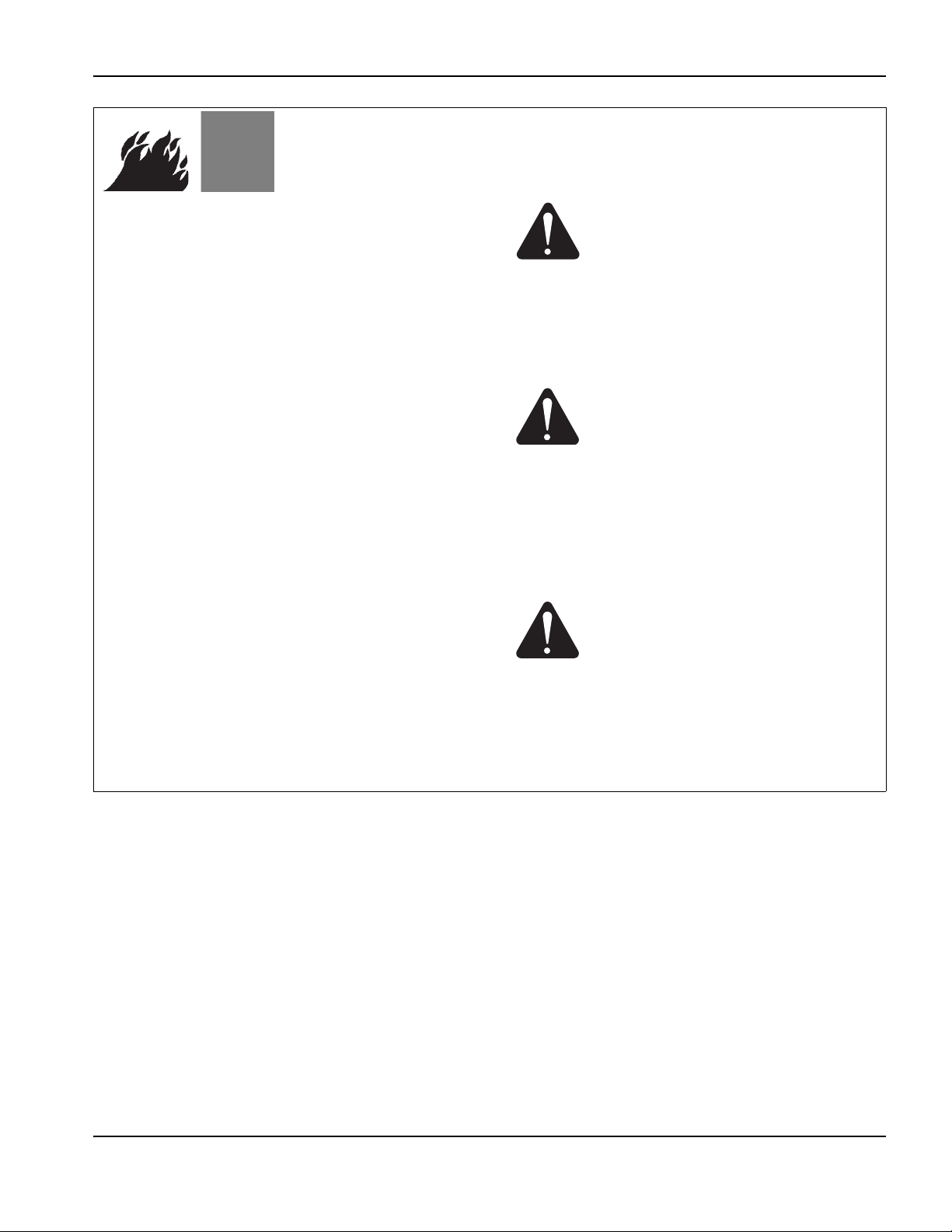
WAR N I NG
Explosion Hazard
Argon-Hydrogen and Methane
Hydrogen and methane are flammable gases that
present an explosion hazard. Keep flames away from
cylinders and hoses that contain methane or hydrogen
mixtures. Keep flames and sparks away from the torch
when using methane or argon-hydrogen plasma.
WAR N I NG
Hydrogen Detonation with
Aluminum Cutting
• Do not cut aluminum underwater or with water
touching the underside of the aluminum.
• Cutting aluminum underwater or with the water
touching the underside of the aluminum can result in
an explosive condition that can detonate during
plasma cutting operations.
WAR N I NG
Explosion Hazard
Underwater Cutting with Fuel Gases
• Do not cut under water with fuel gases containing
hydrogen.
• Cutting under water with fuel gases containing
hydrogen can result in an explosive condition that
can detonate during plasma cutting operations.
Safety and Compliance SC-17
Page 18

Safety
TOXIC FUMES CAN CAUSE INJURY OR DEATH
The plasma arc by itself is the heat source used for
cutting. Accordingly, although the plasma arc has not
been identified as a source of toxic fumes, the material
being cut can be a source of toxic fumes or gases that
deplete oxygen.
Fumes produced vary depending on the metal that is
cut. Metals that may release toxic fumes include, but are
not limited to, stainless steel, carbon steel, zinc
(galvanized), and copper.
In some cases, the metal may be coated with a
substance that could release toxic fumes. Toxic coatings
include, but are not limited to, lead (in some paints),
cadmium (in some paints and fillers), and beryllium.
Gases produced by plasma cutting vary based on the
material to be cut and the method of cutting, but may
include ozone, oxides of nitrogen, hexavalent chromium,
hydrogen, and other substances if such are contained in
or released by the material being cut.
Caution should be taken to minimize exposure to fumes
produced by any industrial process. Depending upon
the chemical composition and concentration of the
fumes (as well as other factors, such as ventilation),
there may be a risk of physical illness, such as birth
defects or cancer.
It is the responsibility of the equipment and site owner
to test the air quality in the area where the equipment is
used and to ensure that the air quality in the workplace
meets all local and national standards and regulations.
The air quality level in any relevant workplace depends
on site-specific variables such as:
• Table design (wet, dry, underwater).
• Material composition, surface finish, and composition
of coatings.
• Volume of material removed.
• Duration of cutting or gouging.
• Size, air volume, ventilation and filtration of the work
area.
• Personal protective equipment.
• Number of welding and cutting systems in operation.
• Other site processes that may produce fumes.
If the workplace must conform to national or local
regulations, only monitoring or testing done at the site
can determine whether the site is above or below
allowable levels.
To reduce the risk of exposure to fumes:
• Remove all coatings and solvents from the metal
before cutting.
• Use local exhaust ventilation to remove fumes from
the air.
• Do not inhale fumes. Wear an air-supplied respirator
when cutting any metal coated with, containing, or
suspected to contain toxic elements.
• Assure that those using welding or cutting
equipment, as well as air-supplied respiration
devices, are qualified and trained in the proper use of
such equipment.
• Never cut containers with potentially toxic materials
inside. Empty and properly clean the container first.
• Monitor or test the air quality at the site as needed.
• Consult with a local expert to implement a site plan
to ensure safe air quality.
SC-18 Safety and Compliance
Page 19
GROUNDING SAFETY
Safety
Work cable Attach the work cable securely to the
workpiece or the work table with good metal-to-metal
contact. Do not connect it to the piece that will fall away
when the cut is complete.
Work table Connect the work table to an earth
ground, in accordance with appropriate national and
local electrical codes.
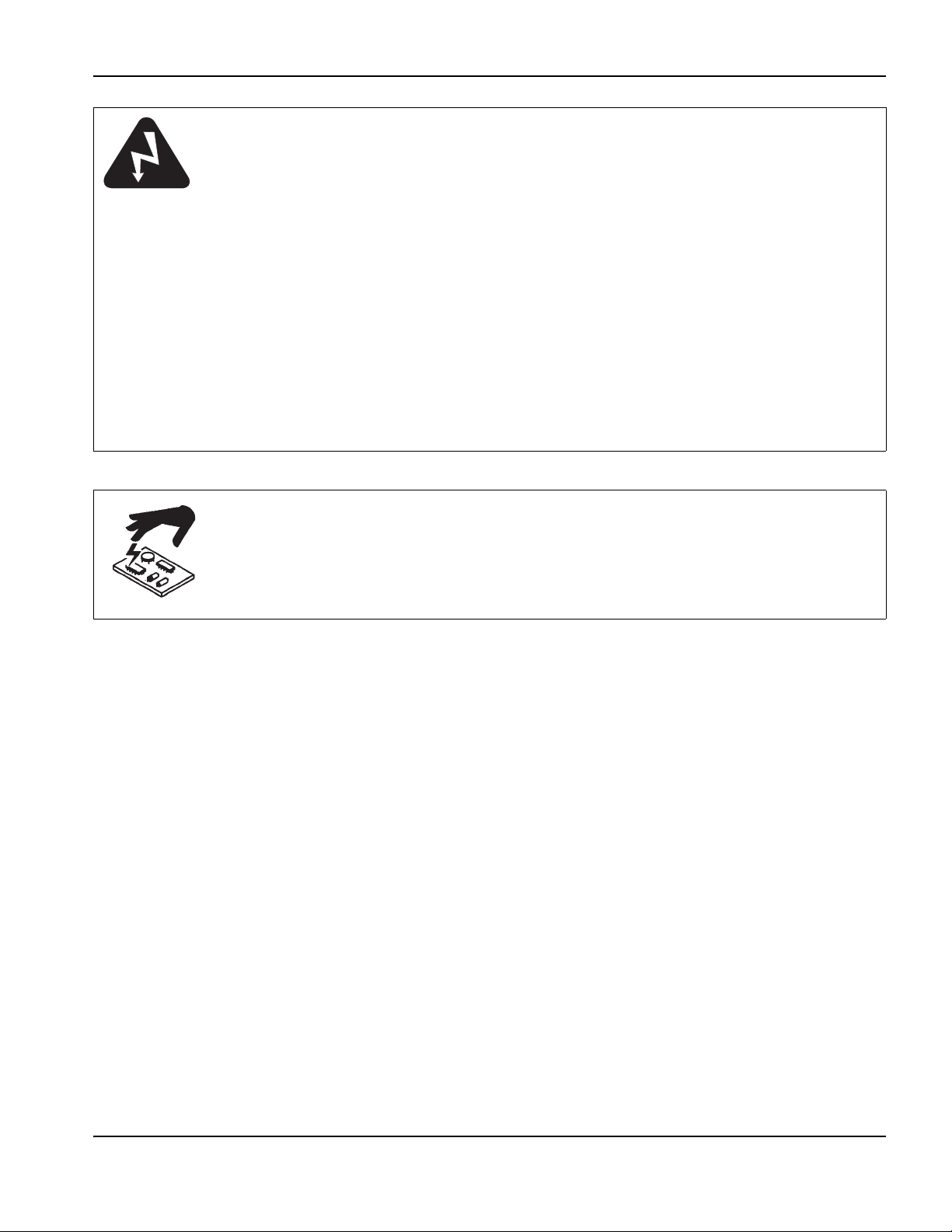
STATIC ELECTRICITY CAN DAMAGE CIRCUIT BOARDS
Use proper precautions when handling printed circuit boards:
• Store PC boards in anti-static containers.
• Wear a grounded wrist strap when handling PC boards.
Input power
• Be sure to connect the power cord ground wire to
the ground in the disconnect box.
• If installation of the plasma system involves
connecting the power cord to the power supply, be
sure to connect the power cord ground wire properly.
• Place the power cord’s ground wire on the stud first,
then place any other ground wires on top of the
power cord ground. Fasten the retaining nut tightly.
• Tighten all electrical connections to avoid excessive
heating.
Safety and Compliance SC-19
Page 20

Safety
COMPRESSED GAS EQUIPMENT SAFETY
• Never lubricate cylinder valves or regulators with oil
or grease.
• Use only correct gas cylinders, regulators, hoses and
fittings designed for the specific application.
• Maintain all compressed gas equipment and
associated parts in good condition.
• Label and color-code all gas hoses to identify the
type of gas in each hose. Consult applicable national
and local codes.
GAS CYLINDERS CAN EXPLODE IF DAMAGED
Gas cylinders contain gas under high pressure.
If damaged, a cylinder can explode.
• Handle and use compressed gas cylinders in
accordance with applicable national and local codes.
• Never use a cylinder that is not upright and secured
in place.
• Keep the protective cap in place over valve except
when the cylinder is in use or connected for use.
• Never allow electrical contact between the plasma
arc and a cylinder.
• Never expose cylinders to excessive heat, sparks,
slag or open flame.
• Never use a hammer, wrench or other tool to open a
stuck cylinder valve.
A PLASMA ARC CAN CAUSE INJURY AND BURNS
Instant-on torches
Plasma arc comes on immediately when the torch
switch is activated.
The plasma arc will cut quickly through gloves and skin.
• Keep away from the torch tip.
• Do not hold metal near the cutting path.
• Never point the torch toward yourself or others.
SC-20 Safety and Compliance
Page 21

ARC RAYS CAN BURN EYES AND SKIN
Eye protection Plasma arc rays produce intense
visible and invisible (ultraviolet and infrared) rays that
can burn eyes and skin.
• Use eye protection in accordance with applicable
national and local codes.
• Wear eye protection (safety glasses or goggles with
side shields, and a welding helmet) with appropriate
lens shading to protect your eyes from the arc’s
ultraviolet and infrared rays.
Skin protection Wear protective clothing to protect
against burns caused by ultraviolet light, sparks, and hot
metal.
• Gauntlet gloves, safety shoes and hat.
• Flame-retardant clothing to cover all exposed areas.
• Cuffless trousers to prevent entry of sparks and slag.
• Remove any combustibles, such as a butane lighter
or matches, from your pockets before cutting.
Cutting area Prepare the cutting area to reduce
reflection and transmission of ultraviolet light:
• Paint walls and other surfaces with dark colors to
reduce reflection.
• Use protective screens or barriers to protect others
from flash and glare.
• Warn others not to watch the arc. Use placards or
signs.
Safety
Minimum
Arc current
(amps)
protective shade
number
(ANSIZ49.1:2005)
Less than 40 A
41 to 60 A
61 to 80 A
81 to 125 A
126 to 150 A
151 to 175 A
176 to 250 A
251 to 300 A
301 to 400 A
401 to 800 A
5589
6689
8889
8989
89810
89811
89812
89813
912913
10 14 10 N /A
Safety and Compliance SC-21
Suggested shade
number for
comfort
OSHA 29CFR
1910.133(a)(5)
EN168:2002
(ANSI Z49.1:2005)
Europe
Page 22

Safety
PACEMAKER AND HEARING AID OPERATION
Pacemaker and hearing aid operation can be affected
by magnetic fields from high currents.
Pacemaker and hearing aid wearers should consult a
doctor before going near any plasma arc cutting and
gouging operations.
NOISE CAN DAMAGE HEARING
Cutting with a plasma arc can exceed acceptable noise
levels as defined by local codes in many applications.
Prolonged exposure to excessive noise can damage
hearing. Always wear proper ear protection when
cutting or gouging, unless sound pressure level
measurements taken at the installed site have verified
personal hearing protection is not necessary per
relevant international, regional, and local codes.
Significant noise reduction can be obtained by adding
simple engineering controls to cutting tables such as
barriers or curtains positioned between the plasma arc
and the workstation; and/or locating the workstation
away from the plasma arc. Implement administrative
controls in the workplace to restrict access, limit
operator exposure time, screen off noisy working areas
and/or take measures to reduce reverberation in
working areas by putting up noise absorbers.
To reduce magnetic field hazards:
• Keep both the work cable and the torch lead to one
side, away from your body.
• Route the torch leads as close as possible to the
work cable.
• Do not wrap or drape the torch lead or work cable
around your body.
• Keep as far away from the power supply as possible.
Use ear protectors if the noise is disruptive or if there is
a risk of hearing damage after all other engineering and
administrative controls have been implemented. If
hearing protection is required, wear only approved
personal protective devices such as ear muffs or ear
plugs with a noise reduction rating appropriate for the
situation. Warn others in the area of possible noise
hazards. In addition, ear protection can prevent hot
splatter from entering the ear.
A PLASMA ARC CAN DAMAGE FROZEN PIPES
Frozen pipes may be damaged or can burst if you attempt to thaw them with a plasma torch.
SC-22 Safety and Compliance
Page 23

DRY DUST COLLECTION INFORMATION
Safety
At some sites, dry dust can represent a potential
explosion hazard.
The U.S. National Fire Protection Association’s 2007
edition of NFPA standard 68, “Explosion Protection by
Deflagration Venting,” provides requirements for the
design, location, installation, maintenance, and use of
devices and systems to vent combustion gases and
pressures after any deflagration event. Consult with the
manufacturer or installer of any dry dust collection
system for applicable requirements before you install a
new dry dust collection system or make significant
changes in the process or materials used with an
existing dry dust collection system.
Consult your local “Authority Having Jurisdiction” (AHJ)
to determine whether any edition of NFPA 68 has been
“adopted by reference” in your local building codes.
Refer to NFPA68 for definitions and explanations of
regulatory terms such as deflagration, AHJ, adopted by
reference, the Kst value, deflagration index, and other
terms.
Note 1 – Hypertherm’s interpretation of these new
requirements is that unless a site-specific evaluation
has been completed to determine that all dust
generated is not combustible, the 2007 edition of
NFPA 68 requires the use of explosion vents designed
to the worst-case Kst value (see annex F) that could be
generated from dust so that the explosion vent size and
type can be designed. NFPA 68 does not specifically
identify plasma cutting or other thermal cutting
processes as requiring deflagration venting systems,
but it does apply these new requirements to all dry dust
collection systems.
Note 2 – Users of Hypertherm manuals should consult
and comply with all applicable federal, state, and local
laws and regulations. Hypertherm does not, by the
publication of any Hypertherm manual, intend to urge
action that is not in compliance with all applicable
regulations and standards, and this manual may never
be construed as doing so.
Safety and Compliance SC-23
Page 24

Safety
LASER RADIATION
Exposure to the laser output can result in serious eye injury. Avoid direct eye exposure.
For your convenience and safety, on Hypertherm products that use a laser, one of the following laser radiation labels
has been applied on the product near where the laser beam exits the enclosure. The maximum output (mV),
wavelength emitted (nM) and, if appropriate, the pulse duration is also provided.
Additional laser safety instructions:
• Consult with an expert on local laser regulations.
Laser safety training may be required.
• Do not allow untrained persons to operate the laser.
Lasers can be dangerous in the hands of untrained
users.
• Do not look into the laser aperture or beam at any
time.
• Position the laser as instructed to avoid unintentional
eye contact.
• Do not use the laser on reflective workpieces.
• Do not use optical tools to view or reflect the laser
beam.
• Do not disassemble or remove the laser or aperture
cover.
ADDITIONAL SAFETY INFORMATION
1. ANSI Standard Z49.1, Safety in Welding and Cutting,
American Welding Society, 550 LeJeune Road P.O. Box
351020, Miami, FL 33135
2. ANSI Standard Z49.2, Fire Prevention in the Use of Cutting
and Welding Processes, American National Standards Institute
1430 Broadway, New York, NY 10018
3. ANSI Standard Z87.1, Safe Practices for Occupation and
Educational Eye and Face Protection, American National
Standards Institute, 1430 Broadway, New York, NY 10018
4. AWS F4.1, Recommended Safe Practices for the Preparation
for Welding and Cutting of Containers and Piping That Have
Held Hazardous Substances, American Welding Society 550
LeJeune Road, P.O. Box 351040, Miami, FL 33135
5. AWS F5.2, Recommended Safe Practices for Plasma Arc
Cutting, American Welding Society 550 LeJeune Road, P.O.
Box 351040, Miami, FL 33135
• Modifying the laser or product in any way can
increase the risk of laser radiation.
• Use of adjustments or performance of procedures
other than those specified in this manual may result
in hazardous laser radiation exposure.
• Do not operate in explosive atmospheres, such as in
the presence of flammable liquids, gases, or dust.
• Use only laser parts and accessories that are
recommended or provided by the manufacturer for
your model.
• Repairs and servicing MUST be performed by
qualified personnel.
• Do not remove or deface the laser safety label.
6. CGA Pamphlet P-1, Safe Handling of Compressed Gases in
Cylinders, Compressed Gas Association 1235 Jefferson Davis
Highway, Arlington, VA 22202
7. CSA Standard W117.2, Code for Safety in Welding and
Cutting, Canadian Standards Association Standard Sales
178 Rexdale Boulevard, Rexdale, Ontario M9W 1R3, Canada
8. NFPA Standard 51B, Cutting and Welding Processes,
National Fire Protection Association 470 Atlantic Avenue,
Boston, MA 02210
9. NFPA Standard 70–1978, National Electrical Code, National
Fire Protection Association, 470 Atlantic Avenue, Boston, MA
02210
10. OSHA, Safety and Health Standards, 29FR 1910 U.S.
Government Printing Office, Washington, D.C. 20402
11. AWS Safety and Health Fact Sheets, American Welding
Society 550 LeJeune Road, P.O. Box 351040, Miami, FL
33135 www.aws.org/technical/facts/
SC-24 Safety and Compliance
Page 25
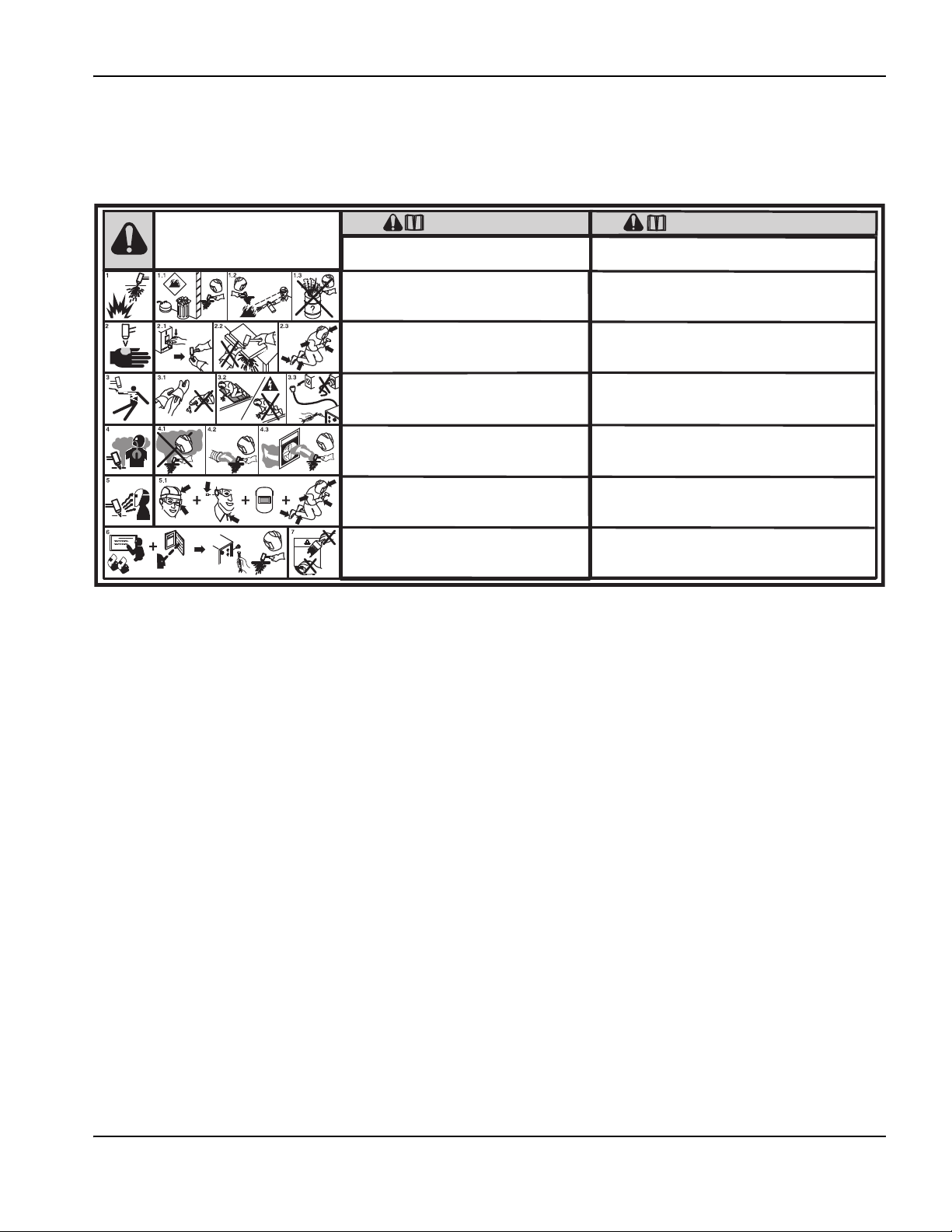
WARNING LABELS
Read and follow these instructions, employer safety
practices, and material safety data sheets. Refer to
ANS Z49.1, “Safety in Welding, Cutting and Allied
Processes” from American Welding Society
(http://www.aws.org) and OSHA Safety and Health
Standards, 29 CFR 1910 (http://www.osha.gov).
WARNING
1. Cutting sparks can cause explosion or fire.
1.1 Do not cut near flammables.
1.2 Have a fire extinguisher nearby and ready to use.
1.3 Do not use a drum or other closed container as a cutting table.
2. Plasma arc can injure and burn; point the nozzle away
from yourself. Arc starts instantly when triggered.
2.1 Turn off power before disassembling torch.
2.2 Do not grip the workpiece near the cutting path.
2.3 Wear complete body protection.
3. Hazardous voltage. Risk of electric shock or burn.
3.1 Wear insulating gloves. Replace gloves when wet or damaged.
3.2 Protect from shock by insulating yourself from work and ground.
3.3 Disconnect power before servicing. Do not touch live parts.
4. Plasma fumes can be hazardous.
4.1 Do not inhale fumes.
4.2 Use forced ventilation or local exhaust to remove the fumes.
4.3 Do not operate in closed spaces. Remove fumes with ventilation.
6. Become trained.
Only qualified personnel should operate this
equipment. Use torches specified in the manual. Keep non-qualified
personnel and children away.
5. Arc rays can burn eyes and injure skin.
5.1 Wear correct and appropriate protective equipment to protect
head, eyes, ears, hands, and body. Button shirt collar. Protect ears
from noise. Use welding helmet with the correct shade of filter.
7. Do not remove, destroy, or cover this label.
Replace if it is missing, damaged, or worn (PN 110584 Rev C).
Plasma cutting can be injurious to operator and persons
in the work area. Consult manual before operating. Failure
to follow all these safety instructions can result in death.
AVERTISSEMENT
Le coupage plasma peut être préjudiciable pour l’opérateur et les personnes qui se
trouvent sur les lieux de travail. Consulter le manuel avant de faire fonctionner. Le
non respect des ces instructions de sécurité peut entraîner la mort.
1. Les étincelles de coupage peuvent provoquer une explosion
ou un incendie.
1.1 Ne pas couper près des matières inflammables.
1.2 Un extincteur doit être à proximité et prêt à être utilisé.
1.3 Ne pas utiliser un fût ou un autre contenant fermé comme table de coupage.
2. L’arc plasma peut blesser et brûler; éloigner la buse de soi.
Il s’allume instantanément quand on l’amorce;
2.1 Couper l’alimentation avant de démonter la torche.
2.2 Ne pas saisir la pièce à couper de la trajectoire de coupage.
2.3 Se protéger entièrement le corps.
3. Tension dangereuse. Risque de choc électrique ou de brûlure.
3.1 Porter des gants isolants. Remplacer les gants quand ils sont humides ou
endommagés.
3.2 Se protéger contre les chocs en s’isolant de la pièce et de la terre.
3.3 Couper l’alimentation avant l’entretien. Ne pas toucher les pièces sous tension.
4. Les fumées plasma peuvent être dangereuses.
4.1 Ne pas inhaler les fumées
4.2 Utiliser une ventilation forcée ou un extracteur local pour dissiper les fumées.
4.3 Ne pas couper dans des espaces clos. Chasser les fumées par ventilation.
5. Les rayons d’arc peuvent brûler les yeux et blesser la peau.
5.1 Porter un bon équipement de protection pour se protéger la tête, les yeux, les
oreilles, les mains et le corps. Boutonner le col de la chemise. Protéger les oreilles
contre le bruit. Utiliser un masque de soudeur avec un filtre de nuance appropriée.
6. Suivre une formation. Seul le personnel qualifié a le droit de faire
fonctionner cet équipement. Utiliser exclusivement les torches indiquées dans le
manual. Le personnel non qualifié et les enfants doivent se tenir à l’écart.
7. Ne pas enlever, détruire ni couvrir cette étiquette.
La remplacer si elle est absente, endommagée ou usée (PN 110584 Rev C).
This warning label is affixed to some power supplies. It is important that the operator and maintenance technician
understand the intent of these warning symbols as described.
Safety
Safety and Compliance SC-25
Page 26
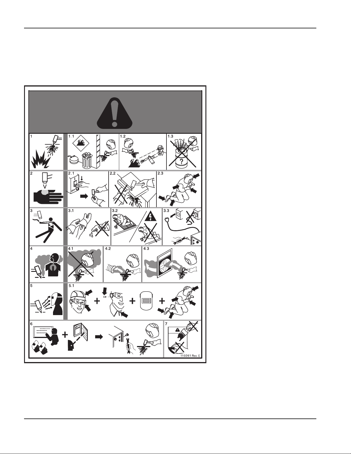
Safety
Warning labels
This warning label is affixed to some power supplies. It is important that the
operator and maintenance technician understand the intent of these
warning symbols as described. The numbered text corresponds to the
numbered boxes on the label.
1. Cutting sparks can cause explosion
or fire.
1.1 Do not cut near flammables.
1.2 Have a fire extinguisher nearby and
ready to use.
1.3 Do not use a drum or other closed
container as a cutting table.
2. Plasma arc can injure and burn; point
the nozzle away from yourself. Arc
starts instantly when triggered.
2.1 Turn off power before disassembling
torch.
2.2 Do not grip the workpiece near the
cutting path.
2.3 Wear complete body protection.
3. Hazardous voltage. Risk of electric
shock or burn.
3.1 Wear insulating gloves. Replace
gloves when wet or damaged.
3.2 Protect from shock by insulating
yourself from work and ground.
3.3 Disconnect power before servicing.
Do not touch live parts.
4. Plasma fumes can be hazardous.
4.1 Do not inhale fumes.
4.2 Use forced ventilation or local exhaust
to remove the fumes.
4.3 Do not operate in closed spaces.
Remove fumes with ventilation.
5. Arc rays can burn eyes and injure
skin.
5.1 Wear correct and appropriate
protective equipment to protect head,
eyes, ears, hands, and body. Button
shirt collar. Protect ears from noise.
Use welding helmet with the correct
shade of filter.
6. Become trained. Only qualified
personnel should operate this
equipment. Use torches specified in
the manual. Keep non-qualified
personnel and children away.
7. Do not remove, destroy, or cover this
label. Replace if it is missing,
damaged, or worn.
SC-26 Safety and Compliance
Page 27

Safety
s
Symbols and marks
Your product may have one or more of the following markings on or near the data plate. Due to differences and conflicts
in national regulations, not all marks are applied to every version of a product.
S mark
The S mark indicates that the power supply and torch are suitable for operations carried out in environments
with increased hazard of electrical shock according to IEC 60974-1.
CSA mark
Products with a CSA mark meet the United States and Canadian regulations for product safety. The products
were evaluated, tested, and certified by CSA-International. Alternatively, the product may have a mark by one
of the other Nationally Recognized Testing Laboratories (NRTL) accredited in both the United States and
Canada, such as UL or TÜV.
CE mark
The CE marking signifies the manufacturer’s declaration of conformity to applicable European directives and
standards. Only those versions of products with a CE marking located on or near the data plate have been
tested for compliance with the European Low Voltage Directive and the European Electromagnetic
Compatibility (EMC) Directive. EMC filters needed to comply with the European EMC Directive are
incorporated within versions of the product with a CE marking.
Eurasian Customs Union (CU) mark
CE versions of products that include an EAC mark of conformity meet the product safety and EMC
requirements for export to Russia, Belarus, and Kazakhstan.
GOST-TR mark
CE versions of products that include a GOST-TR mark of conformity meet the product safety and EMC
requirements for export to the Russian Federation.
C-Tick mark
CE versions of products with a C-Tick mark comply with the EMC regulations required for sale in Australia
and New Zealand.
CCC mark
The China Compulsory Certification (CCC) mark indicates that the product has been tested and found
compliant with product safety regulations required for sale in China.
UkrSEPRO mark
The CE versions of products that include a UkrSEPRO mark of conformity meet the product safety and EMC
requirements for export to the Ukraine.
Serbian AAA mark
CE versions of products that include a AAA Serbian mark meet the product safety and EMC requirements for
export to Serbia.
Safety and Compliance SC-27
Page 28

Safety
SC-28 Safety and Compliance
Page 29

Product Stewardship
Introduction
Hypertherm maintains a global Regulatory Management
System to ensure that products comply with regulatory
and environmental requirements.
National and local safety regulations
National and Local safety regulations shall take
precedence over any instructions provided with the
product. The product shall be imported, installed,
operated and disposed of in accordance with national and
local regulations applicable to the installed site.
Certification test marks
Certified products are identified by one or more
certification test marks from accredited testing
laboratories. The certification test marks are located on or
near the data plate.
Each certification test mark means that the product and its
safety-critical components conform to the relevant
national safety standards as reviewed and determined by
that testing laboratory. Hypertherm places a certification
test mark on its products only after that product is
manufactured with safety-critical components that have
been authorized by the accredited testing laboratory.
Once the product has left the Hypertherm factory, the
certification test marks are invalidated if any of the
following occurs:
Voltage Directive and the European EMC Directive. EMC
filters needed to comply with the European EMC Directive
are incorporated within versions of the power supply with
a CE Marking.
Certificates of compliance for Hypertherm products are
available from the Downloads Library on the Hypertherm
web site at https://www.hypertherm.com.
Differences in national standards
Nations may apply different performance, safety or other
standards. National differences in standards include, but
are not limited to:
•Voltages
• Plug and cord ratings
• Language requirements
• Electromagnetic compatibility requirements
These differences in national or other standards may make
it impossible or impractical for all certification test marks to
be placed on the same version of a product. For example,
the CSA versions of Hypertherm’s products do not
comply with European EMC requirements, and therefore
do not have a CE marking on the data plate.
Countries that require CE marking or have compulsory
EMC regulations must use CE versions of Hypertherm
products with the CE marking on the data plate. These
include, but are not limited to:
• The product is modified in a manner that creates a
hazard or non-conformance with the applicable
standards.
• Safety-critical components are replaced with
unauthorized spare parts.
• Any unauthorized assembly, or accessory that uses or
generates a hazardous voltage is added.
• There is any tampering with a safety circuit or other
feature that is designed into the product as part of the
certification, or otherwise.
CE marking constitutes a manufacturer’s declaration of
conformity to applicable European directives and
standards. Only those versions of Hypertherm products
with a CE Marking located on or near the data plate have
been tested for compliance with the European Low
• Australia
• New Zealand
• Countries in the European Union
•Russia
It is important that the product and its certification test
mark be suitable for the end-use installation site. When
Hypertherm products are shipped to one country for
export to another country; the product must be configured
and certified properly for the end-use site.
Safety and Compliance SC-29
Page 30

Product Stewardship
Safe installation and use of shape cutting equipment
IEC 60974-9, titled Arc Welding Equipment – Installation
and use, provides guidance in the safe installation and use
of shape cutting equipment and the safe performance of
cutting operations. The requirements of national and local
regulations shall be taken into consideration during
installation, including, but not limited to, grounding or
protective earth connections, fuses, supply disconnecting
device, and type of supply circuit. Read these instructions
before installing the equipment. The first and most
important step is the safety assessment of the installation.
The safety assessment must be performed by an expert,
and determines what steps are necessary to create a safe
environment, and what precautions should be adopted
during the actual installation and operation.
Procedures for periodic inspection and testing
Where required by local national regulations,
IEC 60974-4 specifies test procedures for periodic
inspection and after repair or maintenance, to ensure
electrical safety for plasma cutting power sources built in
conformity with IEC 60974-1. Hypertherm performs the
continuity of the protective circuit and insulation
resistance tests in the factory as non-operating tests.
The tests are performed with the power and ground
connections removed.
Hypertherm also removes some protective devices that
would cause false test results. Where required by local
national regulations, a label shall be attached to the
equipment to indicate that it has passed the tests
prescribed by IEC 60974-4. The repair report shall
indicate the results of all tests unless an indication is made
that a particular test has not been performed.
Qualification of test personnel
Electrical safety tests for shape cutting equipment can be
hazardous and shall be carried out by an expert in the field
of electrical repair, preferably someone also familiar with
welding, cutting, and allied processes. The safety risks to
personnel and equipment, when unqualified personnel are
performing these tests, may be much greater than the
benefit of periodic inspection and testing.
Residual current devices (RCDs)
In Australia and some other countries, local codes may
require the use of a Residual Current Devices (RCD)
when portable electrical equipment is used in the
workplace or at construction sites to protect operators
from electrical faults in the equipment. RCDs are
designed to safely disconnect the mains electrical supply
when an imbalance is detected between the supply and
return current (there is a leakage current to earth). RCDs
are available with both fixed and adjustable trip currents
between 6 to 40 milliamperes and a range of trip times up
to 300 milliseconds selected for the equipment
installation, application and intended use. Where RCDs
are used, the trip current and trip time on RCDs should be
selected or adjusted high enough to avoid nuisance
tripping during normal operation of the plasma cutting
equipment and low enough in the extremely unlikely event
of an electrical fault in the equipment to disconnect the
supply before the leakage current under a fault condition
can pose a life threatening electrical hazard to operators.
To verify that the RCDs continue to function properly over
time, both the trip current and the trip time should be
tested periodically. Portable electrical equipment and
RCDs used in commercial and industrial areas in Australia
and New Zealand are tested to the Australian standard
AS/NZS 3760. When you test the insulation of plasma
cutting equipment to AS/NZS 3760, measure the
insulation resistance according to Appendix B of the
standard, at 250 VDC with the power switch in the ON
position to verify proper testing and to avoid the false
failure of the leakage current test. False failures are
possible because the metal oxide varistors (MOVs) and
electromagnetic compatibility (EMC) filters, used to
reduce emissions and protect the equipment from power
surges, may conduct up to 10 milliamperes leakage
current to earth under normal conditions.
If you have any questions regarding the application or
interpretation of any IEC standards described here, you
are required to consult with an appropriate legal or other
advisor familiar with the International Electrotechnical
standards, and shall not rely on Hypertherm in any respect
regarding the interpretation or application of such
standards.
Hypertherm recommends that only visual inspection be
performed unless the electrical safety tests are specifically
required by local national regulations in the country where
the equipment is installed.
SC-30 Safety and Compliance
Page 31

Higher-level systems
When a system integrator adds additional equipment;
such as cutting tables, motor drives, motion controllers or
robots; to a Hypertherm plasma cutting system, the
combined system may be considered a higher-level
system. A higher-level system with hazardous moving
parts may constitute industrial machinery or robotic
equipment, in which case the OEM or end-use customer
may be subject to additional regulations and standards
than those relevant to the plasma cutting system as
manufactured by Hypertherm.
It is the responsibility of the end-use customer and the
OEM to perform a risk assessment for the higher-level
system, and to provide protection against hazardous
moving parts. Unless the higher-level system is certified
when the OEM incorporates Hypertherm products into it,
the installation also may be subject to approval by local
authorities. Seek advice from legal counsel and local
regulatory experts if you are uncertain about compliance.
Product Stewardship
External interconnecting cables between component parts
of the higher level system must be suitable for
contaminants and movement as required by the final end
use installation site. When the external interconnecting
cables are subject to oil, dust, water, or other
contaminants, hard usage ratings may be required.
When external interconnecting cables are subject to
continuous movement, constant flexing ratings may be
required. It is the responsibility of the end-use customer or
the OEM to ensure the cables are suitable for the
application. Since there are differences in the ratings and
costs that can be required by local regulations for higher
level systems, it is necessary to verify that any external
interconnecting cables are suitable for the end-use
installation site.
Safety and Compliance SC-31
Page 32

Product Stewardship
SC-32 Safety and Compliance
Page 33

Environmental Stewardship
Introduction
The Hypertherm Environmental Specification requires
RoHS, WEEE and REACH substance information to be
provided by Hypertherm’s suppliers.
Product environmental compliance does not address the
indoor air quality or environmental release of fumes by the
end user. Any materials that are cut by the end user are
not provided by Hypertherm with the product. The end
user is responsible for the materials being cut as well as
for safety and air quality in the workplace. The end user
must be aware of the potential health risks of the fumes
released from the materials being cut and comply with all
local regulations.
National and local environmental regulations
National and local environmental regulations shall take
precedence over any instructions contained in this
manual.
The product shall be imported, installed, operated and
disposed of in accordance with all national and local
environmental regulations applicable to the installed site.
The European Environmental regulations are discussed
later in The WEEE Directive.
“CE Marking” on the data plate of CE versions of
Powermax series units shipped since 2006. Parts
used in CSA versions of Powermax and other products
manufactured by Hypertherm that are either out of scope
or exempt from RoHS are continuously being converted to
RoHS compliance in anticipation of future requirements.
Proper disposal of Hypertherm products
Hypertherm plasma cutting systems, like all electronic
products, may contain materials or components, such
as printed circuit boards, that cannot be discarded with
ordinary waste. It is your responsibility to dispose of any
Hypertherm product or component part in an
environmentally acceptable manner according to national
and local codes.
• In the United States, check all federal, state, and local
laws.
• In the European Union, check the EU directives,
national, and local laws. For more information, visit
www.hypertherm.com/weee.
• In other countries, check national and local laws.
• Consult with legal or other compliance experts when
appropriate.
The WEEE directive
The RoHS directive
Hypertherm is committed to complying with all applicable
laws and regulations, including the European Union
Restriction of Hazardous Substances (RoHS) Directive
that restricts the use of hazardous materials in electronics
products. Hypertherm exceeds RoHS Directive
compliance obligations on a global basis.
Hypertherm continues to work toward the reduction of
RoHS materials in our products, which are subject to the
RoHS Directive, except where it is widely recognized that
there is no feasible alternative.
Declarations of RoHS Conformity have been prepared for
the current CE versions of Powermax plasma cutting
systems manufactured by Hypertherm. There is also a
“RoHS mark” on the Powermax CE versions below the
On January 27, 2003, the European Parliament and
the Council of the European Union authorized Directive
2002/96/EC or WEEE (Waste Electrical and Electronic
Equipment).
As required by the legislation, any Hypertherm product
covered by the directive and sold in the EU after August
13, 2005 is marked with the WEEE symbol. This directive
encourages and sets specific criteria for the collection,
handling, and recycling of EEE waste. Consumer and
business-to-business wastes are treated differently
(all Hypertherm products are considered
business-to-business). Disposal instructions for the
CE versions of Powermax plasma systems can be found
at www.hypertherm.com/weee.
Safety and Compliance SC-33
Page 34

Environmental Stewardship
The URL is printed on the symbol-only warning label for
each of these CE version Powermax series units shipped
since 2006. The CSA versions of Powermax and other
products manufactured by Hypertherm are either out of
scope or exempt from WEEE.
The REACH regulation
The REACH regulation (1907/2006), in force since
June1, 2007, has an impact on chemicals available to the
European market. The REACH regulation requirements for
component manufacturers states that the component shall
not contain more than 0.1% by weight of the Substances
of Very High Concern (SVHC).
Component manufacturers and other downstream users,
such as Hypertherm, are obligated to obtain assurances
from its suppliers that all chemicals used in or on
Hypertherm products will have a European Chemical
Agency (ECHA) registration number. To provide
chemical information as required by the REACH
regulation, Hypertherm requires suppliers to provide
REACH declarations and identify any known use of
REACH SVHC. Any use of SVHC in amounts exceeding
0.1% w/w of the parts has been eliminated. The MSDS
contains a full disclosure of all substances in the chemical
and can be used to verify REACH SVHC compliance.
The lubricants, sealants, coolants, adhesives, solvents,
coatings and other preparations or mixtures used by
Hypertherm in, on, for, or with its shape cutting equipment
are used in very small quantities (except the coolant) and
are commercially available with multiple sources that can
and will be replaced in the event of a supplier problem
associated with REACH Registration or REACH
Authorization (SVHCs).
Proper handling and safe use of chemicals
Chemical Regulations in the USA, Europe, and other
locations require that Material Safety Data Sheets
(MSDS) be made available for all chemicals. The list of
chemicals is provided by Hypertherm. The MSDS are for
chemicals provided with the product and other chemicals
used in or on the product. MSDS can be downloaded
from the Downloads Library on the Hypertherm web site
at https://www.hypertherm.com. On the Search screen,
insert MSDS in the document title and click on Search.
Hypertherm does not manufacture or provide the materials
that are cut and has no knowledge whether the fumes
released from materials that are cut will pose a physical
hazard or health risk. Please consult with your supplier
or other technical advisor if you need guidance
concerning the properties of the material you will cut
using a Hypertherm product.
Fumes emission and air quality
Note: The following information on air quality is intended
for general information only and should not be used as
a substitute for reviewing and implementing applicable
government regulations or legal standards in the country
where the cutting equipment will be installed and
operated.
In the USA, the National Institute for Occupational Safety
and Health (NIOSH) Manual of Analytical Methods
(NMAM) is a collection of methods for sampling and
analyzing contaminants in workplace air. Methods
published by others, such as OSHA, MSHA, EPA, ASTM,
ISO or commercial suppliers of sampling and analytical
equipment, may have advantages over NIOSH methods.
For example, ASTM Practice D 4185 is a standard
practice for the collection, dissolution, and determination
of trace metals in workplace atmospheres. The sensitivity,
detection limit, and optimum working concentrations for
23 metals are listed in ASTM D 4185. An industrial
hygienist should be used to determine the optimum
sampling protocol, considering analytical accuracy, cost,
and optimum sample number. Hypertherm uses a third
party industrial hygienist to perform and interpret air
quality testing results taken by air sampling equipment
positioned at operator stations in Hypertherm buildings
where plasma cutting tables are installed and operated.
Where applicable, Hypertherm also uses a third party
industrial hygienist to obtain air and water permits.
If you are not fully aware and up to date on all applicable
government regulations and legal standards for the
installation site, you should consult a local expert prior
to purchasing, installing, and operating the equipment.
In the USA, OSHA does not require Material Safety
Data Sheets for articles such as electrodes, swirl rings,
retaining caps, nozzles, shields, deflectors and other solid
parts of the torch.
SC-34 Safety and Compliance
Page 35

Shrink-wrap License Agreement
ENTERING INTO THE LICENSE AGREEMENT SET FORTH BELOW (THE “LICENSE AGREEMENT”) GIVES YOU
THE RIGHT TO USE THE HYPERTHERM TECHNOLOGY AND RELATED SOFTWARE AND EMBODIED THEREIN
WITH HYPERTHERM HPR XD PLASMA SYSTEMS.
PLEASE READ THE LICENSE AGREEMENT CAREFULLY BEFORE USING THE SOFTWARE.
YOUR RIGHT TO USE THE HYPERTHERM TECHNOLOGY AND RELATED SOFTWARE EMBODIED THEREIN IS
SUBJECT TO YOUR AGREEMENT TO BE BOUND BY THE TERMS AND CONDITIONS OF THE LICENSE
AGREEMENT. BY ACTIVATING YOUR CONTROL PLATFORM AND/OR RELATED SOFTWARE PLATFORM, YOU
ACKNOWLEDGE YOUR ACCEPTANCE OF THE LICENSE AGREEMENT AND REPRESENT THAT YOU ARE
AUTHORIZED TO ENTER INTO THE LICENSE AGREEMENT ON BEHALF OF LICENSEE. IF YOU DO NOT
AGREE TO THESE TERMS AND CONDITIONS, HYPERTHERM DOES NOT GRANT YOU THE RIGHT TO USE
THE HYPERTHERM TECHNOLOGY OR RELATED SOFTWARE.
1. Certain definitions: “Designated Hypertherm Patents
12/466,786, and 12/557,920, including foreign equivalents, and any patents issuing therefrom; “Hypertherm Plasma
Systems” shall mean Hypertherm HPR XD plasma systems, including 130, 260 and 400 amp systems; “Hypertherm
Technology” shall mean Hypertherm’s proprietary hole cutting technology, including know-how, specifications,
inventions, methods, procedures, algorithms, software, programs, works of authorship and other information,
documentation and materials for use in programming and operating an automated high temperature thermal cutting
system; “Controller Platform
supplied with this license; and “End User Customer(s)
Technology for such entity’s own internal business purposes and not for distribution to others.
2. The End User Customer shall be granted a non-exclusive, non-transferable, personal license, without the right to
sublicense, to use the Hypertherm Technology, for internal business purposes only, solely as incorporated within the
Controller Platform and solely for use in conjunction with Hypertherm Plasma Systems.
3. The End User Customer shall be granted a non-exclusive, non-transferable, personal, royalty-free license, without the
right to sublicense, under the Designated Hypertherm Patents solely to the extent necessary to enable the End User
Customer to exercise the rights granted under Paragraph 2, above. The License Agreement shall provide that, except
for the rights expressly granted to the End User Customer in the License Agreement, the license under the
Designated Hypertherm Patents shall not be deemed to grant any license or immunity for combining the Hypertherm
Technology with other items or for the use of such combination.
4. The licenses granted to the End User Customer under Paragraphs 2 and 3, above, shall expressly be made subject
to the following limitations and restrictions, and the End User Customer’s agrees that it shall not (and shall not permit
any third party to): (a) use or permit the use of the Hypertherm Technology in conjunction with any high temperature
thermal cutting systems other than Hypertherm Plasma Systems; (b) remove, alter or obscure any copyright,
trademark or other proprietary or restrictive notice or legend on or within the Hypertherm Technology; (c) disclose,
sublicense, distribute or otherwise make available the Hypertherm Technology to any third party or permit others to
use it; (d) provide timesharing, service bureau, data processing or other services to a third party whereby such third
party would obtain the benefits of the Hypertherm Technology for its own end-user purposes through the End User
Customer; (e) decompile, disassemble, or otherwise reverse engineer or attempt to deconstruct or discover any
source code or underlying ideas or algorithms of the Hypertherm Technology by any means whatsoever; (f) assign,
rent, lease, sell or otherwise transfer the Hypertherm Technology; or (g) modify or alter the Hypertherm Technology in
any manner whatsoever or create derivative works thereof.
5. The License Agreement shall provide that nothing therein shall be construed as granting the End User Customer any
right or license under any intellectual property right of Hypertherm or any of its licensors or suppliers by implication,
estoppel or otherwise, except as expressly set forth in the License Agreement.
” shall mean Hypertherm computer numerical controller and/or MTC software platform
” shall mean United States Patent Application Nos. 12/341,731,
” shall mean an entity licensed to use the Hypertherm
Safety and Compliance SC-35
Page 36

Shrink-wrap License Agreement
6. The License Agreement shall provide that Hypertherm shall retain sole and exclusive ownership of the Hypertherm
Technology and that the End User Customer shall obtain no rights in the Hypertherm Technology, except for those
expressly set forth in the sublicense agreement.
7. The License Agreement shall give Hypertherm the right to terminate the agreement effective immediately upon
written notice if the End User Customer breaches any provision of the License Agreement and fails to cure such
breach within five (5) days after receiving written notice thereof from Hypertherm.
8. HYPERTHERM, ITS LICENSORS AND SUPPLIERS MAKE NO REPRESENTATIONS OR WARRANTIES,
EXPRESS OR IMPLIED, WITH RESPECT TO THE HYPERTHERM TECHNOLOGY OR RELATED SOFTWARE
EMBODIED THEREIN, AND DISCLAIM ALL IMPLIED WARRANTIES, INCLUDING, WITHOUT LIMITATION,
THE IMPLIED WARRANTIES OF MERCHANTABILITY AND FITNESS FOR A PARTICULAR PURPOSE.
WITHOUT LIMITING THE FOREGOING, NEITHER HYPERTHERM NOR ANY OF ITS LICENSORS OR
SUPPLIERS MAKES ANY REPRESENTATION OR WARRANTY REGARDING THE FUNCTIONALITY,
RELIABILITY OR PERFORMANCE OF THE HYPERTHERM TECHNOLOGY OR RELATED SOFTWARE
EMBODIED THEREIN, OR THE RESULTS TO BE OBTAINED THROUGH THE USE OF THE HYPERTHERM
TECHNOLOGY OR RELATED SOFTWARE, OR THAT THE OPERATION OF SUCH HYPERTHERM
TECHNOLOGY OR RELATED SOFTWARE WILL BE UNINTERRUPTED OR ERROR-FREE.
9. TO THE MAXIMUM EXTENT PERMITTED BY APPLICABLE LAW, IN NO EVENT SHALL HYPERTHERM, ITS
LICENSORS OR SUPPLIERS BE LIABLE FOR ANY INDIRECT, EXEMPLARY, PUNITIVE, CONSEQUENTIAL,
INCIDENTAL OR SPECIAL DAMAGES, INCLUDING LOST PROFITS, ARISING OUT OF OR IN CONNECTION
WITH THE USE OF THE HYPERTHERM TECHNOLOGY OR RELATED SOFTWARE EMBODIED THEREIN,
EVEN IF SUCH PARTY HAS BEEN ADVISED OF THE POSSIBILITY OF SUCH DAMAGES. THE LIMITATION
STATED IN THIS SECTION SHALL APPLY REGARDLESS OF THE FORM OF ACTION, WHETHER THE
ASSERTED LIABILITY OR DAMAGES ARE BASED ON CONTRACT (INCLUDING, BUT NOT LIMITED TO,
BREACH OF WARRANTY), TORT (INCLUDING, BUT NOT LIMITED TO, NEGLIGENCE), STATUTE, OR ANY
OTHER LEGAL OR EQUITABLE THEORY.
SC-36 Safety and Compliance
Page 37

Section 1
System Tools
Introduction
The Phoenix software offers a suite of tools for performing system-level tasks such as backing up the CNC hard drive and
connecting the CNC to a network. To access the Phoenix system tools, choose Setups > Password > Special Setups
> System.
CAUTION
Using the System Tools requires operational knowledge of the Windows® operating system
and should only be performed by qualified personnel.
Before you begin, connect a mouse and keyboard to the CNC to use System Tools.
Phoenix 9.76.0 Installation and Setup Manual 806410 37
Page 38

1 – System Tools
Automated Backup: Select the frequency of the automatic reminder for the backup of information on the hard drive. At
the selected time, the system displays a prompt to back up the system when you turn it on.
Table Manufacturer Information: Enter the contact information for the cutting table manufacturer. This information
displays when Remote Help starts. You can also change the web server address to show your own Remote
Help server.
38 Phoenix 9.76.0 Installation and Setup Manual 806410
Page 39

CNC performance information
1 – System Tools
The CNC Performance Information parameters display information about processes within the CNC that can contribute
to unreliable motion control. Consult these parameters if the CNC takes longer than expected to load files or perform
operations than it did when it was originally installed.
Each parameter provides the valid range for a process that operates within the CNC. Time values next to each parameter
display the longest time that has been recorded for that process since the CNC was turned on. Values in blue are within
the valid range; values in red are outside the valid range.
To verify CNC performance:
1. From the Main screen, select Setups > Password > Special Setups.
2. Choose the System soft key.
If the numbers for all parameters are blue, the CNC is operating normally.
If the number for any parameter is red, restart the CNC.
3. After restarting the CNC, check the System screen again.
If any number displays in red after the restart, and other programs are running, shut down any other programs so
that Phoenix is the only program running.
If any number still displays in red after shutting down all other programs, contact Hypertherm Technical Service
for assistance.
Phoenix 9.76.0 Installation and Setup Manual 806410 39
Page 40

1 – System Tools
Back up the hard drive
1. From the Main screen, choose Setups > Password > Special Setups.
2. Choose the System soft key.
Press the Backup Hard Drive soft key to use the Norton™ Ghost Utility to save the contents of the main hard drive to a
specified location on the CNC hard drive or to a mapped drive on the network.
After using Norton Ghost, all files on Drive C: will be replaced. Make sure to reload the Phoenix.ini file (or other setup
file) for the system.
40 Phoenix 9.76.0 Installation and Setup Manual 806410
Page 41

1 – System Tools
Scan Hard Disk
To scan the hard disk for viruses or disk errors using Norton Antivirus software:
1. From the Main screen, choose Setups > Password > Special Setups.
2. Choose System > Scan Hard Disk.
3. Select Ye s on the verification popup to start the scan.
4. Select No to scan the hard drive for errors and correct them using the Windows XP CHKDSK (check disk) utility.
This task should be performed approximately every three months depending on the number of files loaded to and
removed from the CNC.
5. The Check Disk (CHKDSK) function cannot operate while the CNC software is in operation. Press “Y” (for yes) to
check the disk the next time that the CNC boots up.
Phoenix 9.76.0 Installation and Setup Manual 806410 41
Page 42

1 – System Tools
Antivirus
The Antivirus feature allows you to search files that are loaded on the CNC for known viruses.
42 Phoenix 9.76.0 Installation and Setup Manual 806410
Page 43

1 – System Tools
Defragment hard disk
The defragmentation operation scans the CNC hard disk for file locations and rearranges them for optimum performance.
This task should be performed approximately every three months.
To defragment the hard disk:
1. From the Main screen, choose Setups > Password > Special Setups.
2. Choose System > Defragment Hard Disk.
Launch an External Program
The Phoenix software provides a method for you to launch a program from a custom soft key on the Main screen. The
following steps create a soft key that launches the Notepad text editor. You can modify the key label and path to launch a
drive tuning, inventory, or other program needed in your environment.
1. Using a text (ASCII) editor such as Windows Notepad, create a file named “external.txt.” This file will contain only two
lines of text.
2. In the first line of text, enter the words that you want to appear on the soft key, in 60 characters or fewer.
3. In the second line of text, enter the path to the program on the Phoenix hard drive.
4. Save the file in the C:\Phoenix folder.
Phoenix 9.76.0 Installation and Setup Manual 806410 43
Page 44

1 – System Tools
A sample external.txt file is shown below:
Notepad
C:\windows\system32\notepad.exe
This file creates the Notepad soft key:
Notes:
Phoenix can support only one custom soft key at a time.
The path to the program must be valid or Phoenix will not display the custom soft key.
The first line cannot exceed 60 characters, including spaces.
The second line can contain spaces.
44 Phoenix 9.76.0 Installation and Setup Manual 806410
Page 45

1 – System Tools
Software installed on the CNC
Hypertherm CNCs have several software modules pre-loaded at the factory. To view the default software modules,
choose Setups > Diagnostics > Control Information. The picture below shows only a portion of the CNC information
screen.
DXF Translator: Hypertherm CNCs can convert simple DXF files into .TXT files for cutting. To learn more about the DXF
file translator, see Chapter 3 Loading Parts in the Phoenix Operator Manual.
Hypernest CNC: Hypertherm CNCs provide Manual and Automatic Nester options that allow the simple nesting of
parts. To learn more about CNC nesting, see Chapter 4 Arranging Parts in the Phoenix Operator Manual.
Neither of the Nester options can nest parts that contain advanced feature codes such
as G59 process selection codes.
MS Security: Microsoft Security Essentials is the virus protection built into the CNC. To learn more, see Antivirus on
page 42.
MS NetMon: Microsoft Network Monitor is the Ethernet monitoring tool built into the CNC. To start the Network Monitor,
choose Setups > Password > Special Setups > System > Start Network Capture.
Phoenix software version number
Follow these steps if you need the Phoenix software version number for service.
1. Choose Setups > Diagnostics > Control Information.
Phoenix 9.76.0 Installation and Setup Manual 806410 45
Page 46

1 – System Tools
2. Under Software versions, the Phoenix version number appears next to Operator Interface.
Phoenix setup files
Hypertherm CNCs save the values that you enter on each screen in the setup file named Phoenix.ini. This file is stored in
the C:\Phoenix folder. The CNC saves the file when you make a change to a value and exit a screen. The CNC also saves
a backup version of the setup file, Phoenix.bak. in the D:\Setups folder on the CNC hard drive.
Setup files can be copied to other Hypertherm CNCs. After configuring a CNC to run a particular cutting system, you can
use that setup file for the next installation of a CNC, table, and tool. When you load a setup file into a CNC, that setup file
overwrites both Phoenix.ini and Phoenix.bak.
EDGE Pro setup files should be used only on other EDGE Pro CNCs. MicroEDGE Pro and EDGE Pro Ti setup files
have the same restriction.
About setup files
The CNC stores multiple copies of the Phoenix.ini setup file.
Phoenix.ini is always the active setup file. Each time you make a change on a screen on the CNC, the changes are
saved to Phoenix.ini. In the Special Setups screen you can save a copy of Phoenix.ini with a different name for a
backup or to use on another CNC. When you load a setup file with another name, the contents of the file overwrite
the contents of Phoenix.ini and Phoenix.bak. Phoenix.ini is stored in the C:\Phoenix folder.
Phoenix.bak is an identical copy of Phoenix.ini. The CNC saves Phoenix.bak each time it saves Phoenix.ini. If
Phoenix.ini becomes corrupted, the CNC loads the settings in Phoenix.bak and creates a new Phoenix.ini.
Phoenix.bak is stored in the D:\Setups folder.
Default.ini is an important backup of Phoenix.ini and is used to restore settings if both Phoenix.ini and Phoenix.bak
become corrupted. Hypertherm recommends that you create the Default.ini when you commission a cutting system.
Default.ini is stored in the hard drive root folder (C:\).
Factory settings represent the contents of the Phoenix.ini file as it was shipped from the factory. Each CNC has
factory settings that represent the available features and axes on that CNC.
Factory settings are stored internally in Phoenix software but are not stored in a specific file. Factory settings may be
very different from the settings on a CNC when it is commissioned in a cutting system at a manufacturing site.
46 Phoenix 9.76.0 Installation and Setup Manual 806410
Page 47

1 – System Tools
Setup files from previous versions of Phoenix
New versions of Phoenix software contain new features with settings that are saved to the Phoenix.ini file. When you load
a setup file from a previous version of Phoenix, a message displays that shows you the new settings that are not in your
setup file. Phoenix loads its factory settings for those settings.
After you load a setup file from a previous version of Phoenix, make sure that you save a new version of the setup file
in the new version of Phoenix. By saving the Phoenix.ini in the new version, the you make sure that the setup file has
settings for all new features in the Phoenix software.
Save and load the setup file
Hypertherm recommends saving the setup file three times when first commissioning a cutting system:
Save the setup file to a memory stick with the name EndUserDate.ini.
Save the setup file to the HD Backup location (D:\Setups) that you select the drop-down of the save dialog box, and
name the file EndUserDateBak.ini.
Save the setup file as Default.ini on the CNC hard drive root folder C:\.
Save a setup file without using a password
The CNC can gather the Phoenix.ini, LastPart.txt, and SystemErrors.log, into a single zip file (Phoenix.zip). Use this
procedure to save the setup file or to gather files to send to Hypertherm Technical Service. Since this method does not
require a password, it provides a convenient way for an end user to save the Phoenix.ini without being exposed to
password-protected settings.
1. Insert a memory stick into a USB port on the CNC.
2. From the Main screen, choose Files > Save to Disk > Save System files to Disk.
3. Choose Save All to Zip. The CNC creates Phoenix.zip and saves it on the memory stick.
Save a setup file with a different name
When you save a setup file under a different name, the CNC continues to use Phoenix.ini and does not update your
saved setup file.
1. Choose Setups > Password > Special Setups.
2. Choose Save Setups.
3. Choose Hard Drive, HD Backups, or Memory Stick for the location.
4. Enter a file name.
5. Choose OK.
The CNC saves the file in the hard drive root folder (C:\), D:\Setups, or the memory stick root folder.
Phoenix 9.76.0 Installation and Setup Manual 806410 47
Page 48

1 – System Tools
Load a setup file
The setup file that you load becomes Phoenix.ini.
1. Choose Setups > Password > Special Setups.
2. Choose Load Setups.
3. Choose Hard Drive or Memory Stick for the location. The CNC lists only the *.ini files that are present in the root
folder of the hard drive or the memory stick.
4. Enter a file name.
5. Choose OK.
Save and load default settings
The CNC uses Default.ini to restore settings if both Phoenix.ini and Phoenix.bak become corrupted.
Save Default.ini
1. Choose Setups > Password > Special Setups.
2. Choose Save Setups.
3. Choose Hard Drive for the location.
4. Enter the Default for the file name.
5. Choose OK.
The CNC creates Default.ini in the hard drive root folder (C:\).
Load Default.ini
Default.ini must exist in C:\. If no Default.ini exists, the CNC provides an option to reload factory settings instead.
1. Choose Setups > Password > Special Setups > System.
2. Choose the Default Setups soft key.
If you haven’t saved a Default.ini file, then the soft key reads Reset Setups and allows you
to reset the CNC to factory settings instead.
48 Phoenix 9.76.0 Installation and Setup Manual 806410
Page 49

1 – System Tools
Reload factory settings
If your system is experiencing motion or other problems for which you cannot find a solution, reloading the factory settings
provides you with a known starting point for configuring the CNC to work with your cutting system.
CAUTION!
Reloading the factory settings changes the setup on the CNC. The cutting system may no longer be
capable of motion and the I/O may not work. Only use this procedure if you do not have a backup
setup file.
1. Choose Setups > Password > Special Setups > System.
2. Choose Reset Setups.
If the soft key label reads Default Setups, then the file Default.ini exists in the hard drive
root folder. Reload the default settings instead of the factory settings if possible.
Phoenix 9.76.0 Installation and Setup Manual 806410 49
Page 50

1 – System Tools
50 Phoenix 9.76.0 Installation and Setup Manual 806410
Page 51

Section 2
Y+
X+
X-
Y-
0,0
Machine Setup
Overview
Phoenix provides several screens that you use to define your cutting system. The screens are accessed with the Machine
Setups password provided to you by your table manufacturer. This section describes setting up your cutting system
including:
Defining axis orientation and positive motion
Identifying all axes on the cutting system
Setting machine speeds
Assigning I/O points
Setting up serial ports
Axis orientation and positive motion
Gantry-table cutting systems are based on the Cartesian coordinate system. Phoenix requires you to define the X axis
and positive motion relative to the table’s 0,0, or absolute home, position. In the Cartesian coordinate system, the X+ and
Y+ motion is represented like this:
Phoenix 9.76.0 Installation and Setup Manual 806410 51
Page 52

2 – Machine Setup
+X
+Y
0, 0
-X
-Y
Gantry
Rail
Rail
The X axis is the first axis Phoenix needs to know about. In a standard orientation, the X axis would be along the gantry.
Phoenix calls the axis along the gantry the Transverse axis. The Y axis is always perpendicular to the X axis. In Phoenix, the
Rail axis is perpendicular to the Transverse. In a standard orientation the Y axis would be along the rail. When a cutting
system has a second rail motor, you select the Dual Gantry axis on the Machine Setups screen in Phoenix.
The following picture shows a cutting table where X is assigned to the gantry, also called Transverse, and Y is assigned to
the Rail.
52 Phoenix 9.76.0 Installation and Setup Manual 806410
Page 53

2 – Machine Setup
+ Z
- Z
+X
+Y
0, 0
-X
+ X
+ Y
0, 0
+ Z
+A
+B
+C
- Y
- Z
- X
Most torch height controls require an axis on the CNC. The Sensor THC, integrated into many Hypertherm CNCs, is also
an axis on the CNC. The Sensor THC axis, or lifter axis, is called a Z axis. Its positive direction is always up (skyward) and
its negative direction is always down (earthward).
The X, Y, and Z axes are all linear axes. To perform angled cutting, the cutting system needs one or more rotational axes to
position the tool or torch on an angle. These axes are commonly known as A, B, and C axes. Many bevel heads provide
two axes of rotation that the CNC coordinates along with the X, Y, and Z motion to position the torch. In a standard
orientation, the A axis rotates about the X axis, the B axis rotates about the Y axis, and the C axis rotates about the Z axis.
Phoenix 9.76.0 Installation and Setup Manual 806410 53
Page 54

2 – Machine Setup
A
B
Phoenix calls this type of
bevel head a Dual Tilting
Rotator.
ABXYZ bevel head
+C
+A
Phoenix calls this type of
bevel head a Tilt-Rotator.
AC bevel head
Most bevel heads provide two axes of rotation. These are known as ABXYZ and AC bevel heads.
54 Phoenix 9.76.0 Installation and Setup Manual 806410
Page 55

2 – Machine Setup
About axis assignments
Hypertherm CNCs are hard-coded with the axis assignments. The table below shows the axis numbers that the CNC
uses for 12 axes, and common letter identifiers for the axes.
Axis Axis assignment
1 Transverse or Rail (X)
2 Rail or Transverse (Y)
3 Dual Gantry (W)
4Sensor THC 1 (Z)
5 Rotate 1 (B or C)
6Tilt 1 (A)
7 Transverse 2
8 Rotate 2
9Tilt 2
10 Sensor THC 2
11 Sensor THC 3
12 Sensor THC 4
All cutting systems require both Transverse and Rail axes, but you can assign either to X or Y.
A Dual Gantry axis is parallel to the Rail axis (think of it as a “Rail 2” axis). In a dual gantry cutting system, the second
rail axis is powered by its own motor using the same signal as the Rail axis.
Rotate and Tilt axes are used for bevel cutting.
Change the axis assignments with passwords
Using special passwords NRT and 1RT (No Rotate Tilt and 1 Rotate Tilt respectively) redirects certain axes signals to
different axis numbers. A 2-station cutting system on a 6-axis CNC requires the NRT password so that the Transverse 2
and Sensor THC 2 signals are output on axes 5 and 6 instead of 7 and 10. (Previously the Transverse 2 axis was available
only on a dual bevel-head cutting system).
Additional examples:
To enable the Transverse 2 axis for pipe or tube cutting on a CNC with 6 or fewer axes, enter the NRT password.
To set up a cutting system with both a straight torch and a bevel head, enter the 1RT password.
The following tables identify the application, password, and axis assignments for common cutting system axis
configurations. Use these tables to identify the axis number, and for SERCOS cutting systems, the drive address where
the CNC will output the axis signals.
Phoenix 9.76.0 Installation and Setup Manual 806410 55
Page 56

2 – Machine Setup
4-axis I-cutting on pipe or tube, no Dual Gantry, NRT password
Axis/drive
address
1 Transverse or Rail
2 Rail or Transverse
3 Sensor THC
4 Transverse 2
5-axis I-cutting on pipe or tube, with Dual Gantry, NRT password
Axis/drive
address
1 Transverse or Rail
2 Rail or Transverse
3 Dual Gantry
4 Sensor THC
5 Transverse 2
6-axis, 2-station, I-cutting on flat plate, with Dual Gantry, NRT password
Axis assignment
Axis assignment
Axis/drive
address
1 Transverse or Rail
2 Rail or Transverse
3 Dual Gantry
4 Sensor THC
5 Transverse 2
6 Sensor THC 2
6-axis bevel cutting on pipe or tube, no Dual Grantry, 1RT password
Axis/drive
address
1 Transverse or Rail
2 Rail or Transverse
3 Sensor THC
4 Transverse 2
5 Rotate
Axis assignment
Axis assignment
6Tilt
56 Phoenix 9.76.0 Installation and Setup Manual 806410
Page 57

7-axis bevel cutting on pipe or tube, with Dual Gantry, 1RT password
2 – Machine Setup
Axis/drive
address
1 Transverse or Rail
2 Rail or Transverse
3 Dual Gantry
4 Sensor THC
5 Rotate
6Tilt
7 Transverse 2
8-axis, 2-station, bevel and I-cutting on flat plate, 1RT password
Axis/drive
address
1 Transverse or Rail
2 Rail or Transverse
3 Dual Gantry
4 Sensor THC
Axis assignment
Axis assignment
5 Rotate
6Tilt
7 Transverse 2
8 Sensor THC 2
Phoenix 9.76.0 Installation and Setup Manual 806410 57
Page 58

2 – Machine Setup
System axis screens
Machine Setups screen
Use the Machine Setups screen to define the machine orientation, choose the axes you have on your cutting system, and
enter the number of torch height controls. To open the Machine Setups screen, choose Setups > Password > Machine
Setups.
X Axis Orientation: Specifies the X axis as the Transverse or Rail axis. The default setting is Transverse.
Up Direction: Defines the machine motion when the ↑ arrow key is pressed in manual mode.
Right Direction: Defines the machine motion when the → arrow key is pressed in manual mode.
X and Y Motor/Encoder: Select Swapped to swap the X and Y axis encoder signals internally. This feature simplifies
the installation of systems with alternative wiring configurations.
Dual Gantry Installed: Select Yes to enable the Dual Gantry axis for a second side drive. The Dual Gantry axis is always
parallel to the Rail axis.
CBH Installed: Select Yes to enable the contour bevel head axis and allow configuration of that axis.
Tilt Rotator Installed: Tilt Rotator describes an ACXYZ bevel head, which as a rotational axis (C) combined with a tilt
axis (A). Choose this option when your cutting system has this type of bevel head installed.
58 Phoenix 9.76.0 Installation and Setup Manual 806410
Page 59

2 – Machine Setup
Dual Tilt Rotator Installed: Choose this option when the cutting system has a second ACXYZ bevel head. Choosing
this option also enables a second transverse axis that can be used for a second straight torch, or for a chuck
to turn round pipe or rectangular tube stock.
Auto Home at Power Up: Determines whether the contour bevel head (CBH) and tilt or rotate axes automatically go
into the homing routine when the CNC powers up.
Follower Initially: Determines whether the CBH and rotate features are always enabled after power up or are enabled
through the part program.
Dual Tilting Rotator: Dual Tilting Rotator describes an ABXYZ bevel head which has two tilt axes (A and B). Choose
this option when your cutting system has this type of bevel head installed. The Tilt Rotator Installed option
must be selected to make Dual Tilting Rotator option available.
Dual Transverse: Enables the Transverse 2 axis for use with a second cutting station or as an axis for a chuck for
holding pipe or tube stock.
Table Size: Enter between the X overtravel switches and the Y overtravel switches. The X and Y dimensions represent
the cutting area of the table and limit the workpiece size dimensions set in the Cutting screen.
Key Press Logging: Records key press and other related information in a daily log file. Service technicians use this log
to review events before a fault. When logging is enabled, the log file is saved to the hard drive so it can be
retrieved by transfer to a USB memory stick. Usually this parameter is set to NO.
ArcGlide THCs Installed: Defines the number of ArcGlide THC axes assigned to the CNC.
Use Hypernet: Sets up the CNC to communicate with the ArcGlide over Hypernet.
Sensor THCs Installed: Defines the total number of Sensor THC axes assigned to the CNC.
THC Installed On Axis / Analog: Defines the torch height control axis. Select the THC, which axis it is installed on,
and the analog input to use for arc voltage feedback.
For more information on the setup and use of the Sensor THC, refer to the other
sections in this chapter, as well as Torch Height Controls in the Phoenix Operator’s
Manual.
Ignore Torch Collision During IHS: Allows the system to ignore input about a torch collision during the initial height
sense cycle. This may be helpful for some THC mechanics.
Command THCs Installed: Enables the Command THC serial link. For more information on this feature, refer to
Configuring Ports on page 87. Shown in Type P mode only.
Auto Torch Spacing: Select Yes to enable the automatic torch spacing feature. This feature uses embedded part
program codes and dedicated outputs to control individual torch stations to set spacing and clamping of
direct and mirrored cutting. For more information, refer to the Phoenix V9 Series Programmer’s Reference.
Phoenix 9.76.0 Installation and Setup Manual 806410 59
Page 60

2 – Machine Setup
Transverse or Rail Axis
The following screen is identical for both the traverse and rail setup.
The CNC comes with both an advanced position and velocity servo loop. The following parameters are available to help
configure the servo loops for your specific drive and mechanical system.
Speed 0 To: Enter speed ranges or breaks. You can set drive tuning parameters (gains) for each speed break. The
speed breaks can be entered here or on the Speed screen. On the Speeds screen you can enter an
Acceleration Rate for each speed break.
Proportional Gain: Proportional gain correlates to elastic stiffness in the control loop. The range of values for this field
is 1 to 500, although setting from 40 to 60 are usual.
Increase the proportional gain to increase the static stiffness, but decrease the response of the servo loop.
Under a proportional loop control, the drive system applies a restoring torque to the motor in proportion to
the position error of the axis. If proportional gain too high, the system and axis become unstable. During
cutting, the torch can overshoot the path. This is also called a “hot” control loop.
If proportional gain is too low, the system response is not precise. This can be seen in the test pattern when
the outside corners become rounded and not all the circle segments meet in the center.
Integral Gain: Integral gain improves the positioning accuracy of the control loop. Integral gain can be used to
compensate for static friction or gravity. Excessive integral gain can result in system instability. For most
shape cutting machines, this parameter should be set to zero (0).
60 Phoenix 9.76.0 Installation and Setup Manual 806410
Page 61

2 – Machine Setup
4000 counts
x
10 rev of motor
x
1 rev
=
X counts
1 revolution 1 rev of pinion 2Π inches inches
1000 line encoder multiplied
by 4 (quadrature) per 1 motor
revolution
10:1 gear ratio
Distance traveled in one
revolution of the pinion
Circumference of pinion (2 inch
diameter multiplied by pi)
Encoder counts per unit
(inches or mm)
Derivative Gain: Derivative gain helps to minimize sudden changes in velocity. The higher the derivative gain, the slower
the response time to the control loop. For most velocity loop drives, this parameter is set to zero (0).
Feedforward Gain: Feedforward gain can be used to drive the following error to zero during machine motion. In all
digital control loops there is a finite amount of error that is introduced by the velocity command. Increasing
feedforward gain can reduce this introduced error.
Velocity Gain: When you use a current loop amplifier, you can use the internal velocity loop in the CNC to provide
dampening without an external tachometer.
Use of the internal velocity loop with a current loop amplifier can result in higher static stiffness, smoother
machine motion, and less overshoot.
Servo Error Tolerance: Servo error, also called following error, is the difference between the commanded motor
position and the actual motor position. The servo error tolerance is the upper limit of the amount of following
error allowed before the CNC faults.
The amount of servo error tolerance depends on the cutting system mechanics. Setting the servo error
tolerance too low could cause the CNC to fault repeatedly. Setting it too high could cause inaccurate
motion or mechanical harm. Set the Following Error parameter in the Watch window and observe
steady-state operation of the cutting system (some following error is normal). Set the servo error tolerance to
a value slightly higher than the steady-state following error.
Encoder Counts per mm (inch): To determine the encoder counts per mm (inch), you will need to know the following
measurements for your encoders:
counts per revolution of the motor
gear ratio
distance of travel in one revolution of the pinion gear
diameter of the pinion gear when it engages the rack
An example of the equation is shown below:
Fault Ramp Time: This parameter sets the motion deceleration time after a fault occurs. At the end of Fault Ramp Time
the drives will be disabled.
Phoenix 9.76.0 Installation and Setup Manual 806410 61
Page 62

2 – Machine Setup
Drive Type: This parameter is used to tell the CNC what type of control loop to run. If you are running an external velocity
loop drive (indicated by having an integrated tachometer in the motor), select Velocity. If you are running in
torque mode (no tachometer), select Current.
DAC Polarity: This parameter allows changing of the analog output polarity to establish proper control loop feedback
without any wiring changes.
Encoder Polarity: This parameter allows changing of the encoder input polarity to establish proper counting for positive
machine motion without any wiring changes.
Encoder Decode Mode: Currently, the CNC only supports 4X encoder decode mode. This has been done to increase
positional accuracy.
Use Hardware Overtravels: Select whether the cutting system will be using hardware overtravel switches. If Hardware
overtravel switches are used, the CNC will disable feedback and display an error message if the inputs
become active. It is recommended that hardware overtravel switches be installed.
Backlash Compensation: The Backlash Compensation parameter is used to offset or compensate for any backlash in
the mechanics of the drive system. The maximum value for backlash compensation is 12.7 mm (.5 in).
Home: The Home parameter is used to activate use of the Home feature. Depending on configuration, the table may be
Homed to either a designated home switch or an overtravel switch.
The Home feature is used to set a known absolute physical position location on the cutting table that is used
for referencing future manual Go to Home and other motion commands. This is generally performed through
activation of a home switch positioned on the appropriate axis giving it a known physical location.
When you enter a homing command, the CNC moves the axis toward the home switches at the Fast Home
Speed until the switches activate. Once the switches activate, motion stops and then the axis moves in the
opposite direction off switch at the Slow Home Speed. The moment that the switch deactivates, the CNC
records the position which provides an absolute reference point for future motion commands.
Absolute Home Position: Defines the position of the axis when the Home Limit Switch or Marker Pulse is detected.
Home Offset Distance: Allows the user to set an offset distance from the Home Limit Switch.
Home Direction: Determines which direction the axes will travel during phase one of the homing sequence.
Use Marker Pulse: When enabled, the absolute home position will be assigned at the instant the marker pulse is
detected. It is recommended that the Marker Pulse be used for optimal homing repeatability.
Use Software Travel Limits: The CNC is capable of running with software travel limits that are based on position.
When enabled, this feature allows you to select Fault or Fast Decel when active. Fault operates as hardware
switches with immediate fault. Fast Decel uses the Fast Deceleration rate set on the Speeds screen to
ramp down motion.
Maximum Travel Limit: If Software Overtravels are enabled, the user is prompted for the maximum travel of the cutting
machine.
Minimum Travel Limit: If Software Overtravels are enabled, the user is prompted for the minimum travel of the cutting
machine.
Laser Compensation: Uses position readings gathered with a laser interferometer to correct the actual position of the
axes (Transverse, Dual Transverse, Rail, and Dual Gantry only).
62 Phoenix 9.76.0 Installation and Setup Manual 806410
Page 63

2 – Machine Setup
Gantry
1
2
3
4
5
Add a hard
stop to the
left of 2.
Need to
allow
enough
space to
stop
without
breaking
your hard
stop
1
Gantry distance between hardware overtravel switches
154 inches (3192 mm)
2 X- overtravel switch at 0.
3
X+ overtravel switch at154 inches (3912 mm)
4
Software minimum travel limit at 3 inches (76 mm) to stop
motion before contact with the hardware overtravel
switch.
5
Software maximum travel limit at 151 inches (3835 mm)
to stop motion before contact with the hardware
overtravel switch.
Using software travel limits
A software travel limit (also called a software overtravel) is a position on the axis that can be reached before the system
contacts a hardware limit switch or hard stop. The drawing below shows measurements from an example system with a
gantry that has 154 inches (3912 mm) of travel on the Transverse axis between the overtravel switches.
The gantry travel distance of 154 inches (3912 mm) also equals the Table Size X dimension on the Machine Setups
screen (Setups > Password > Machine Setups).
Phoenix 9.76.0 Installation and Setup Manual 806410 63
Page 64

2 – Machine Setup
Dual Gantry Axis
The following setup screen is available when you have selected Dual Gantry on the Machine Setups screen.
The Dual Gantry Axis is commanded as a separate axis on the CNC that mirrors the output of the main Rail axis.
Additionally, performance of the Dual Gantry Axis is compared to the main Rail Axis and additional output command is
given to keep the axis in position.
The definitions for the setup parameters are the same as for the Transverse/Rail Axes. However, the number of selections
are reduced because features for overtravels and homing do not apply.
Speed 0 To: This parameter allows the technician to input selected speed ranges to customize the gains for the various
speeds selected.
These speed parameters are directly tied to the Speed To field for the acceleration rates
previously noted on the Speeds setup screen. Changing these speed parameters will
replace the Speed To values entered at the Speeds setup screen.
Proportional Gain: Proportional Gain correlates to Elastic Stiffness in the control loop. Increasing the proportional gain
increases the static stiffness, but decreases response of the servo loop.
Under proportional loop control the drive system will apply a restoring torque to the motor in proportion the
position error of the axis.
64 Phoenix 9.76.0 Installation and Setup Manual 806410
Page 65

2 – Machine Setup
With a Proportional Gain too high, the system will be unstable which will result in overshoots, and a generally
“nervous” and shaky axis. This is also referred to as a “hot” control loop.
With a proportional gain too low, the system will respond in a loose or sloppy manner. This can be seen in
the test pattern when the outside corners become rounded and the circle segments do not all meet in the
center.
Integral Gain: Integral Gain improves the positioning accuracy of the control loop.
Integral gain can be used to compensate for static friction or gravity. Excessive Integral Gain can result in
system instability.
For most shape cutting machines, this parameter should be set to zero (0).
Derivative Gain: Derivative Gain helps to dampen sudden changes in velocity.
The higher the derivative gain, the slower the response time to the control loop.
For most velocity loop drives this parameter should be set to zero (0).
Feedforward Gain: Feedforward Gain can be used to drive the following error to zero during machine motion.
In all digital control loops there is a finite amount of error that is introduced by the velocity command.
Increasing Feedforward Gain can reduce this introduced error.
Velocity Gain: When using a current loop amplifier, the internal velocity loop in the CNC can be used to provide
dampening without an external tachometer.
Using the internal velocity loop with a current loop amplifier can result in higher static stiffness, smoother
machine motion, and less overshoot.
Skew Error Tolerance: If the Dual Gantry Axis is installed, the user will be prompted for Skew Error Tolerance. This is
the amount of position error allowed between the master and slave gantry drive axes prior to an error
message being displayed.
This value should match the value used for the Rail for proper operation.
Encoder Counts per mm (inch): To determine the encoder counts per mm (inch), you will need to know the following
measurements for your encoders:
counts per revolution of the motor
gear ratio
distance of travel in one revolution of the pinion gear
diameter of the pinion gear when it engages the rack
Phoenix 9.76.0 Installation and Setup Manual 806410 65
Page 66

2 – Machine Setup
4000 counts
x
10 rev of motor
x
1 rev
=
X counts
1 revolution 1 rev of pinion 2Π inches inches
1000 line encoder multiplied
by 4 (quadrature) per 1 motor
revolution
10:1 gear ratio
Distance traveled in one
revolution of the pinion
Circumference of pinion (2 inch
diameter multiplied by pi)
Encoder counts per unit
(inches or mm)
An example of the equation is shown below:
Drive Type: This parameter is used to tell the CNC what type of control loop to run. If you are running an external velocity
loop drive (indicated by having an integrated tachometer in the motor), select Velocity. If you are running in
torque mode (no tachometer), select Current.
DAC Polarity: This parameter allows changing the analog output polarity to establish proper control loop feedback
without any wiring changes.
Encoder Polarity: This parameter allows changing the encoder input polarity to establish proper counting for positive
machine motion without any wiring changes.
Encoder Decode Mode: Currently the CNC only supports 4X encoder decode mode. This has been done to increase
positional accuracy.
Use Home Limit Switch: Selecting “Yes” will enable the Home feature for the Dual Gantry Axis.
Switch Offset Distance: The Switch Offset Distance is used to specify any physical position offset between the Dual
Gantry and Rail Home Switch positions. This allows the CNC to position the two axes accurately for
operation and remove any skew of the gantry.
Backlash Compensation: The Backlash Compensation parameter is used to offset or compensate for any backlash in
the mechanics of the drive system.
Laser Compensation: Uses position readings gathered with a laser interferometer to correct the actual position of the
axes (Transverse, Dual Transverse, Rail, and Dual Gantry only).
The Z Home Switch must first be defined and mapped to an input location in the screen
to enable this feature.
66 Phoenix 9.76.0 Installation and Setup Manual 806410
Page 67

CBH Axis
The following setup screen is available if the cutting system has for a contour bevel head.
2 – Machine Setup
Proportional Gain: Proportional Gain correlates to elastic stiffness in the control loop. Increasing the proportional gain
increases the static stiffness, but decreases response of the servo loop.
Under proportional loop control, the drive system will apply a restoring torque to the motor in proportion to
the position error of the axis.
With a Proportional Gain too high, the system will be unstable which will result in overshoots and a generally
“nervous” and shaky axis. This is also referred to as a “hot” control loop.
With a proportional gain too low, the system will respond in a loose or sloppy manner. This can be seen in
the test pattern when the outside corners become rounded and the circle segments do not all meet in the
center.
Integral Gain: Integral Gain improves the positioning accuracy of the control loop.
Integral Gain can be used to compensate for static friction or gravity. Excessive Integral Gain can result in
system instability.
For most shape cutting machines, this parameter should be set to zero (0).
Derivative Gain: Derivative Gain helps to dampen sudden changes in velocity. The higher the Derivative Gain, the
slower the response time to the control loop.
Phoenix 9.76.0 Installation and Setup Manual 806410 67
Page 68

2 – Machine Setup
For most velocity loop drives, this parameter will be set to zero (0).
Feedforward Gain: Feedforward Gain can be used to drive the following error to zero during machine motion. In all
digital control loops there is a finite amount of error that is introduced by the velocity command.
Increasing Feedforward Gain can reduce this introduced error.
Velocity Gain: When using a current loop amplifier, the internal velocity loop in the CNC can be used to provide
dampening without an external tachometer.
Using the internal velocity loop with a current loop amplifier can result in higher static stiffness, smoother
machine motion, and less overshoot.
Servo Error Tolerance: Servo error, also called following error, is the difference between the commanded motor
position and the actual motor position. The servo error tolerance is the upper limit of the amount of following
error allowed before the CNC faults.
The amount of servo error tolerance depends on the cutting system mechanics. Setting the servo error
tolerance too low could cause the CNC to fault repeatedly. Setting it too high could cause inaccurate
motion or mechanical harm. Set the Following Error parameter in the Watch window and observe
steady-state operation of the cutting system (some following error is normal). Set the servo error tolerance to
a value slightly higher than the steady-state following error.
Encoder Counts per rev: Enter a value that is the number of encoder edges per revolution of the Contour Bevel Head
axis.
It is possible to enter fractional encoder units and the CNC will keep track of these fractions automatically.
Encoder Counts per rev are equal to the resolution of the encoder multiplied by the encoder revolutions per
rev.
For example, the resolution of a 4X – 1000 line encoder counts both edges (lines) of channel A and channel
B to equal 4 counts per line time multiplied by the 1000 lines per revolution would equal 4000 counts per
revolution.
Encoder Counts/Rev = 4 Counts/Line x 1000 Lines/Rev = 4000
Drive Type: This parameter is used to tell the CNC what type of control loop to run.
If you are running an external velocity loop drive (indicated by having an integrated tachometer in the motor),
select Velocity. If you are running in torque mode (no tachometer), select Current.
DAC Polarity: This parameter allows changing of the analog output polarity to establish proper control loop feedback
without any wiring changes.
Encoder Polarity: This parameter allows changing of the encoder input polarity to establish proper counting for positive
machine motion without any wiring changes.
Encoder Decode Mode: Currently the CNC only supports 4X encoder decode mode. This has been done to increase
positional accuracy.
Follower Initially: This parameter is used to determine if the CBH axis will be On when the CNC is first powered up.
Auto Home At Power Up: Determines if the contour bevel head will automatically go into the homing routine upon
powering up the CNC.
68 Phoenix 9.76.0 Installation and Setup Manual 806410
Page 69

2 – Machine Setup
Absolute Home Angle: Defines the position of the axis when the home limit switch or marker pulse is detected.
Home Offset Angle: Allows the user to set an offset angle from the home limit switch.
Use Home Limit Switch: Tells the CNC to look for a home limit switch during phase one of the homing sequence.
Home Direction: Determines which direction the axes will travel during phase one of the homing sequence.
Use Marker Pulse: When enabled, the absolute home position will be assigned at the instant the marker pulse is
detected. It is recommended that the marker pulse be used for optimal homing repeatability.
Rotate Axis
In Phoenix, a Rotate Axis is equivalent to a C axis in the standard orientation (X is Transverse and Y is rail).
Proportional Gain: Proportional Gain correlates to Elastic Stiffness in the control loop. Increasing the proportional gain
increases the static stiffness, but decreases response of the servo loop.
Under proportional loop control, the drive system will apply a restoring torque to the motor in proportion to
the position error of the axis.
With a Proportional Gain too high, the system will be unstable which will result in overshoots and a generally
“nervous” and shaky axis. This is also referred to as a “hot” control loop.
Phoenix 9.76.0 Installation and Setup Manual 806410 69
Page 70

2 – Machine Setup
With a proportional gain too low, the system will respond in a loose or sloppy manner. This can be seen in
the test pattern when the outside corners become rounded and the circle segments do not all meet in the
center.
Integral Gain: Integral Gain improves the positioning accuracy of the control loop.
Integral Gain can be used to compensate for static friction or gravity. Excessive Integral Gain can result in
system instability.
For most shape cutting machines, this parameter should be set to zero (0).
Derivative Gain: Derivative Gain helps to dampen sudden changes in velocity. The higher the Derivative Gain, the
slower the response time to the control loop.
For most velocity loop drives, this parameter will be set to zero (0).
Feedforward Gain: Feedforward Gain can be used to drive the following error to zero during machine motion. In all
digital control loops there is a finite amount of error that is introduced by the velocity command.
Increasing Feedforward Gain can reduce this introduced error.
Velocity Gain: When using a current loop amplifier, the internal velocity loop in the CNC can be used to provide
dampening without an external tachometer.
Using the internal velocity loop with a current loop amplifier can result in higher static stiffness, smoother
machine motion, and less overshoot.
Servo Error Tolerance: Servo error, also called following error, is the difference between the commanded motor
position and the actual motor position. The servo error tolerance is the upper limit of the amount of following
error allowed before the CNC faults.
The amount of servo error tolerance depends on the cutting system mechanics. Setting the servo error
tolerance too low could cause the CNC to fault repeatedly. Setting it too high could cause inaccurate
motion or mechanical harm. Set the Following Error parameter in the Watch window and observe
steady-state operation of the cutting system (some following error is normal). Set the servo error tolerance to
a value slightly higher than the steady-state following error.
Encoder Counts per rev: Enter a value that is the number of encoder edges per revolution of the Contour Bevel Head
axis.
It is possible to enter fractional encoder units and the CNC will keep track of these fractions automatically.
Encoder Counts per rev are equal to the resolution of the encoder multiplied by the encoder revolutions per
rev.
For example, the resolution of a 4X – 1000 line encoder counts both edges (lines) of channel A and channel
B to equal 4 counts per line multiplied by the 1000 lines per revolution would equal 4000 counts per
revolution.
Encoder Counts/Rev = 4 Counts/Line x 1000 Lines/Rev = 4000
Drive Type: This parameter is used to tell the CNC what type of control loop to run.
If you are running an external velocity loop drive (indicated by having an integrated tachometer in the motor),
select Velocity. If you are running in torque mode (no tachometer), select Current.
70 Phoenix 9.76.0 Installation and Setup Manual 806410
Page 71

2 – Machine Setup
DAC Polarity: This parameter allows changing the analog output polarity to establish proper control loop feedback
without any wiring changes.
Encoder Polarity: This parameter allows changing of the encoder input polarity to establish proper counting for positive
machine motion without any wiring changes.
Encoder Decode Mode: Currently the CNC only supports 4X encoder decode mode. This has been done to increase
positional accuracy.
Absolute Home Angle: Defines the position of the axis when the home limit switch or marker pulse is detected.
Home Offset Angle: Allows the user to set an offset angle from the home limit switch.
Use Home Limit Switch: Tells the CNC to look for a home limit switch during phase one of the homing sequence.
Home Direction: Determines which direction the axes will travel during phase one of the homing sequence.
Use Marker Pulse: When enabled, the absolute home position will be assigned at the instant the marker pulse is
detected. It is recommended that the marker pulse be used for optimal homing repeatability.
Tilt Axis
In the Phoenix software, the Tilt axis is equivalent to the A axis in the standard orientation (X is transverse and Y is Rail).
Phoenix 9.76.0 Installation and Setup Manual 806410 71
Page 72

2 – Machine Setup
Proportional Gain: Proportional Gain correlates to elastic stiffness in the control loop. Increasing the proportional gain
increases the static stiffness, but decreases response of the servo loop.
Under proportional loop control, the drive system will apply a restoring torque to the motor in proportion to
the position error of the axis.
With a Proportional Gain too high, the system will be unstable which will result in overshoots and a generally
“nervous” and shaky axis. This is also referred to as a “hot” control loop.
With a proportional gain too low, the system will respond in a loose or sloppy manner. This can be seen in
the test pattern when the outside corners become rounded and the circle segments do not all meet in the
center.
Integral Gain: Integral Gain improves the positioning accuracy of the control loop.
Integral Gain can be used to compensate for static friction or gravity. Excessive Integral Gain can result in
system instability.
For most shape cutting machines, this parameter should be set to zero (0).
Derivative Gain: Derivative Gain helps to dampen sudden changes in velocity. The higher the Derivative Gain, the
slower the response time to the control loop.
For most velocity loop drives, this parameter will be set to zero (0).
Feedforward Gain: Feedforward Gain can be used to drive the following error to zero during machine motion. In all
digital control loops there is a finite amount of error that is introduced by the velocity command.
Increasing Feedforward Gain can reduce this introduced error.
Velocity Gain: When using a current loop amplifier, the internal velocity loop in the CNC can be used to provide
dampening without an external tachometer.
Using the internal velocity loop with a current loop amplifier can result in higher static stiffness, smoother
machine motion, and less overshoot.
Servo Error Tolerance: Servo error, also called following error, is the difference between the commanded motor
position and the actual motor position. The servo error tolerance is the upper limit of the amount of following
error allowed before the CNC faults.
The amount of servo error tolerance depends on the cutting system mechanics. Setting the servo error
tolerance too low could cause the CNC to fault repeatedly. Setting it too high could cause inaccurate
motion or mechanical harm. Set the Following Error parameter in the Watch window and observe
steady-state operation of the cutting system (some following error is normal). Set the servo error tolerance to
a value slightly higher than the steady-state following error.
Encoder Counts per rev: Enter a value that is the number of encoder edges per revolution of the Contour Bevel Head
axis.
It is possible to enter fractional encoder units and the CNC will keep track of these fractions automatically.
Encoder Counts per rev are equal to the resolution of the encoder multiplied by the encoder revolutions per
rev.
72 Phoenix 9.76.0 Installation and Setup Manual 806410
Page 73

2 – Machine Setup
For example, the resolution of a 4X – 1000 line encoder counts both edges (lines) of channel A and channel
B to equal 4 counts per line time multiplied by the 1000 lines per revolution would equal 4000 counts per
revolution.
Encoder Counts/Rev = 4 Counts/Line x 1000 Lines/Rev = 4000
Encoder Polarity: This parameter allows changing of the encoder input polarity to establish proper counting for positive
machine motion without any wiring changes.
DAC Polarity: This parameter allows changing of the analog output polarity to establish proper control loop feedback
without any wiring changes.
Drive Type: This parameter is used to tell the CNC what type of control loop to run.
If you are running an external velocity loop drive (indicated by having an integrated tachometer in the motor),
select Velocity. If you are running in torque mode (no tachometer), select Current.
Current Limit: If you selected Current for Drive Type, set the maximum current output for operation of the lifter motor.
Encoder Decode Mode: Currently the CNC only supports 4X encoder decode mode. This has been done to increase
positional accuracy.
Use Hardware Overtravels: Select whether the cutting system will be using hardware overtravel switches. If Hardware
overtravel switches are used, the CNC will disable feedback and display an error message if the inputs
become active. It is recommended that hardware overtravel switches be installed.
Absolute Home Angle: Defines the position of the axis when the home limit switch or marker pulse is detected.
Home Offset Angle: Allows the user to set an offset angle from the home limit switch.
Homing with Overtravel Switch: Activates the Home feature and uses the Overtravel Switch as its reference.
The Home feature is used to set a known absolute physical position location for the tilt axis.
Home Direction: Determines which direction the axes will travel during phase one of the homing sequence.
Use Marker Pulse: When enabled, the absolute home position will be assigned at the instant the marker pulse is
detected. It is recommended that the marker pulse be used for optimal homing repeatability.
Use Software Travel Limits: The CNC is capable of running with software overtravel limits that are based on position.
When enabled, this feature allows you to select Fault or Fast Decel when active. Fault operates as hardware
switches with immediate fault. Fast Decel uses the fast decel value to ramp down motion.
Maximum Travel Limit: If Software Overtravels are enabled, the user is prompted for the maximum travel of the cutting
machine.
Minimum Travel Limit: If Software Overtravels are enabled, the user is prompted for the minimum travel of the cutting
machine.
Phoenix 9.76.0 Installation and Setup Manual 806410 73
Page 74

2 – Machine Setup
Transverse 2 Axis
The Transverse 2 axis is also called a Dual Transverse axis. It can be used for either a second cutting station or as an axis
that turns a chuck for pipe or rectangular tube cutting.
Speed 0 To: Specifies speed ranges and customizes the acceleration rates for these speeds. When a speed range that
is lower than the maximum speed is entered, a new range at the maximum machine speed setting is created.
You can set a maximum of 5 speed ranges.
To reduce the number of Speed To ranges, enter the maximum speed in the highest range and the additional
range fields will be removed from the screen.
Proportional Gain: Proportional Gain correlates to elastic stiffness in the control loop. Increasing the proportional gain
increases the static stiffness, but decreases response of the servo loop.
Under proportional loop control, the drive system will apply a restoring torque to the motor in proportion to
the position error of the axis.
With a Proportional Gain too high, the system will be unstable which will result in overshoots and a generally
“nervous” and shaky axis. This is also referred to as a “hot” control loop.
With a proportional gain too low, the system will respond in a loose or sloppy manner. This can be seen in
the test pattern when the outside corners become rounded and the circle segments do not all meet in the
center.
74 Phoenix 9.76.0 Installation and Setup Manual 806410
Page 75

2 – Machine Setup
Integral Gain: Integral Gain improves the positioning accuracy of the control loop.
Integral Gain can be used to compensate for static friction or gravity. Excessive Integral Gain can result in
system instability.
For most shape cutting machines, this parameter should be set to zero (0).
Derivative Gain: Derivative Gain helps to dampen sudden changes in velocity. The higher the Derivative Gain, the
slower the response time to the control loop.
For most velocity loop drives, this parameter will be set to zero (0).
Feedforward Gain: Feedforward Gain can be used to drive the following error to zero during machine motion. In all
digital control loops there is a finite amount of error that is introduced by the velocity command.
Increasing Feedforward Gain can reduce this introduced error.
Velocity Gain: When using a current loop amplifier, the internal velocity loop in the CNC can be used to provide
dampening without an external tachometer.
Using the internal velocity loop with a current loop amplifier can result in higher static stiffness, smoother
machine motion, and less overshoot.
Servo Error Tolerance: Servo error, also called following error, is the difference between the commanded motor
position and the actual motor position. The servo error tolerance is the upper limit of the amount of following
error allowed before the CNC faults.
The amount of servo error tolerance depends on the cutting system mechanics. Setting the servo error
tolerance too low could cause the CNC to fault repeatedly. Setting it too high could cause inaccurate
motion or mechanical harm. Set the Following Error parameter in the Watch window and observe
steady-state operation of the cutting system (some following error is normal). Set the servo error tolerance to
a value slightly higher than the steady-state following error.
Encoder Counts per mm (inch): To determine the encoder counts per mm (inch), you will need to know the following
measurements for your encoders:
counts per revolution of the motor
gear ratio
distance of travel in one revolution of the pinion gear
diameter of the pinion gear when it engages the rack
Phoenix 9.76.0 Installation and Setup Manual 806410 75
Page 76

2 – Machine Setup
4000 counts
x
10 rev of motor
x
1 rev
=
X counts
1 revolution 1 rev of pinion 2Π inches inches
1000 line encoder multiplied
by 4 (quadrature) per 1 motor
revolution
10:1 gear ratio
Distance traveled in one
revolution of the pinion
Circumference of pinion (2 inch
diameter multiplied by pi)
Encoder counts per unit
(inches or mm)
An example of the equation is shown below:
Fault Ramp Time: This parameter sets the motion deceleration time after a fault occurs. At the end of “Fault Ramp Time,
The drives will be disabled.
Drive Type: This parameter is used to tell the CNC what type of control loop to run.
If you are running an external velocity loop drive (indicated by having an integrated tachometer in the motor),
select Velocity. If you are running in torque mode (no tachometer), select Current.
DAC Polarity: This parameter allows changing of the analog output polarity to establish proper control loop feedback
without any wiring changes.
Encoder Polarity: This parameter allows changing of the encoder input polarity to establish proper counting for positive
machine motion without any wiring changes.
Encoder Decode Mode: Currently the CNC only supports 4X encoder decode mode. This has been done to increase
positional accuracy.
Use Hardware Overtravels: Select whether the cutting system will be using hardware overtravel switches. If Hardware
overtravel switches are used, the CNC will disable feedback and display an error message if the inputs
become active. It is recommended that hardware overtravel switches be installed.
Backlash Compensation: The Backlash Compensation parameter is used to offset or compensate for any backlash in
the mechanics of the drive system.
Minimum Head Spacing: Sets the minimum distance that is allowed between the Transverse 1 and Transverse 2 axes.
Home: The Home parameter is used to activate use of the Home feature. Depending on configuration, the table may be
Homed to either a designated Home Switch or an Overtravel Switch.
The Home feature is used to set a known absolute physical position location on the cutting table that is used
for referencing future manual Go to Home and other motion commands. This is generally performed through
activation of a home switch positioned on the appropriate axis giving it a known physical location.
76 Phoenix 9.76.0 Installation and Setup Manual 806410
Page 77

2 – Machine Setup
When you enter a homing command, the CNC moves the axis toward the home switches at the Fast Home
Speed until the switches activate. Once the switches activate, motion stops and then the axis moves in the
opposite direction off switch at the Slow Home Speed. The moment that the switch deactivates, the CNC
records the position which provides an absolute reference point for future motion commands.
Absolute Home Position: Defines the position of the axis when the Home Limit Switch or Marker Pulse is detected.
Home Offset Distance: Allows the user to set an offset distance from the Home Limit Switch.
Home Direction: Determines which direction the axes will travel during phase one of the homing sequence.
Use Marker Pulse: When enabled, the absolute home position will be assigned at the instant the marker pulse is
detected. It is recommended that the Marker Pulse be used for optimal homing repeatability.
Use Software Travel Limits: The CNC is capable of running with software Overtravel limit switches based on position.
When enabled, this feature allows the user to select the fault logic of fault or Fast Decel when active. Fault
operates as hardware switches with immediate fault. Fast Decel uses the fast Decel value to ramp down
motion.
Maximum/Minimum Travel Limit: If Software Overtravels are enabled, the user is prompted for the maximum or
minimum travel of the cutting machine.
Mirrored Marker Offsets: Allows preset tool offsets to be performed as mirrored motion for the transverse 2 axis.
Laser Compensation: Uses position readings gathered with a laser interferometer to correct the actual position of the
axes (Transverse, Dual Transverse, Rail, and Dual Gantry only).
Phoenix 9.76.0 Installation and Setup Manual 806410 77
Page 78

2 – Machine Setup
Laser Mapping
The Laser Mapping screen provides an interface for the laser interferometer. The CNC uses the parameters in the Laser
Mapping screen to generate a CNC part program that allows the laser interferometer to map the position of each drive
axis (rail, transverse, and dual gantry) at specified points (or targets).
After the parameters are set and the laser interferometer is connected to the axis, press the mapping soft key for the
appropriate axis. The CNC will automatically load and run the part program.
Rail/Transverse First Run: The direction of the first run on the Rail or Transverse axis. The selection should be based
on the direction of motion from home position.
Reversal Distance: The distance of travel in the opposite direction at the beginning and end of a run.
Use: Reverse motion removes mechanical backlash before mapping the axis.
Target Distance: Sets the distance between targets.
Use: This value should be 20 inches or more.
Number of Targets: The number of pauses on each run where the laser interferometer measures the physical position of
the axis. The part program that the CNC creates for mapping includes a pause (dwell) at each of these
targets.
Use: Enter values between 2 and 1000.
78 Phoenix 9.76.0 Installation and Setup Manual 806410
Page 79

2 – Machine Setup
Target Dwell: The amount of time that motion pauses at each target to allow the interferometer to take each
measurement and record the results.
Use: Refer to the instruction manual for your laser interferometer to determine how to set this value.
Mapping Speed: The program speed of the part program that the CNC creates for mapping.
Number of Runs: The number of runs that the interferometer makes on the axis. Set this to a minimum of 2.
Use: Set this to an even number between 2 and 1000 because the interferometer must travel to the end of
the axis and then return. The greater the number of runs, the more precise the motion compensation can be.
Setting Speeds
The Speeds setup screen is where you set the machine speeds for the operating modes.
The CNC is capable of operating over a wide range of speeds, depending on the drives, motors, gearboxes, and
mechanics of the system.
Speed 0 To: Specifies speed ranges (or breaks) and customizes the acceleration rates for these speeds. When a speed
range that is lower than the maximum speed is entered, a new range at the maximum machine speed setting
is created. You can set a maximum of 5 speed ranges.
To reduce the number of Speed To ranges, enter the maximum speed in the highest range and the additional
range fields will be removed from the screen.
Phoenix 9.76.0 Installation and Setup Manual 806410 79
Page 80

2 – Machine Setup
Acceleration Rate: Determines both the acceleration and deceleration rate for all motion.
All mechanical systems have different acceleration and deceleration rates to move the cutting device
smoothly. The higher the acceleration rate, the quicker the machine will get up to speed. The lower the
acceleration rate, the smoother the machine will position the cutting device.
Enter a value in milliGs for the desired acceleration rate. One milliG is approximately 0.384 inches per
2
second
. A recommended, initial value for this field is 10 milliGs.
Peak S Curve Acceleration displays the maximum acceleration used during the beginning of a cut and represents a
rate of acceleration that is 50% greater than the average rate of acceleration. This parameter appears when
S Curve Acceleration (at the lower left in the Speeds Screen) is set to Yes.
Fast Deceleration Rate: This parameter is activated by the Fast Stop or Torch Collision inputs and specifies in milliGs
how quickly the system will stop when the Fast Stop Input is active. Generally, this value is much higher than
the acceleration rate.
2
One milliG is approximately 0.384 inches per second
.
Maximum Machine Speed: Enter the maximum value at which the system is capable of contouring. This parameter
limits the range of all subsequent speed entries. In addition, it scales the speedometer in the Watch Window
during runtime operation.
The maximum speed at which the CNC can contour can be calculated with the following equation.
Maximum Contouring Rate (IPM) =
60 seconds
minute user edges second
x
1 inch
x
100,000 edges
For example: the CNC could command a cutting machine with 4000 edges per inch resolution at 1,500
IPM.
Limited Machine Speed: Defines maximum machine speed when the Limited Speed Input is active. This is commonly
used to set a reduced machine speed for increased safety during machine testing or maintenance.
High Jog Speed: Defines the high speed for manual motion.
Medium Jog Speed: Defines the medium speed for manual motion.
Low Jog Speed: Defines the low speed for manual motion.
Minimum Corner Speed: Defines the minimum speed to use when negotiating corners. The CNC has centripetal
velocity and acceleration contouring algorithms which provide optimal cut quality for most cut operations. In
some situations, a minimum corner speed prevents over-burning at corners. In normal operations, this
parameter should be set to zero.
Fast Home Speed: Defines the speed that the CNC uses during the first phase of the homing sequence. During the
first phase, the cutting device moves toward the home limit switches at the fast rate.
Slow Home Speed: Defines the speed that the CNC uses during the second phase of the homing sequence. During
the second phase, the cutting device moves off the home limit switch and proceeds to the marker pulse.
When the CNC detects the marker pulse, it decelerates to a stop and performs a small move in the opposite
direction to the marker pulse.
80 Phoenix 9.76.0 Installation and Setup Manual 806410
Page 81

2 – Machine Setup
Creep Speed Percentage: Defines what percentage of the machine cut speed will be used when creeping. Generally,
creep speed is 25% of the cut speed.
Torch Height Disable Speed: Specifies the percentage of the program cut speed at which the CNC disables the
height control. For example, when the cutting system is slowed to cut a part feature such as a corner, the arc
voltage increases which would cause the torch to lower into the workpiece. When the cutting system slows
down to this percentage of the cut speed, the CNC disables THC voltage tracking.
For more information, see the Torch Height Disable section in this chapter.
Distance Before THD Speed: This distance is active whenever the program cut speed drops below the Torch Height
Disable Speed, or segments intersect at an angle greater than the tangent angle. Specifies the distance
before turning a corner at which the CNCs disables the torch height control.
Distance After THD Speed: Specifies the distance after turning a corner to enable voltage tracking for torch height
control. Distance After THD Speed is active whenever the speed drops below the Torch Height Disable
Speed, or segments intersect at an angle greater than the tangent angle.
S-curve Acceleration: Select Yes to enable S-curve acceleration. Select No to use trapezoidal acceleration.
Depending on the application and table mechanics, S-curve acceleration can reduce or eliminate “jerk” that
results from trapezoidal motion. See S-Curve acceleration later in this section for more information.
CBH Speeds
The CBH speed setup parameters display only if they have been enabled.
CBH Acceleration Rate: Specifies the acceleration rate for smooth and stable movement of the contoured bevel head.
The higher the acceleration rate, the quicker the CBH reaches cutting speed. The lower the acceleration
rate, the smoother the machine will position the cutting device. Values are entered in revolutions/second
Maximum CBH Speed: Specifies the maximum speed for the CBH rotation in revolutions/minute.
CBH High Jog / Home Speed: Specifies the manual CBH jog and fast Home speed.
CBH Low Jog / Home Speed: Specifies the CBH slow home speed.
2.
THC Speeds
The THC speed setup parameters display only if a Sensor THC has been set up on the Machine Setups screen.
THC Acceleration Rate: Specifies the acceleration rate for smooth and stable movement of the Sensor THC. The
higher the acceleration rate, the quicker the THC reaches cutting speed. The lower the acceleration rate, the
smoother the machine will position the cutting device. Values are entered in milliGs.
Maximum THC Speed: Specifies the maximum speed for the Sensor THC in inches / minute.
THC Jog Speed: Specifies the THC jog speed.
THC Home/Fast IHS Speed: Specifies the speed that is used to home the torch at the top of the slide and to move the
torch from the selected IHS height until it senses the workpiece.
Phoenix 9.76.0 Installation and Setup Manual 806410 81
Page 82

2 – Machine Setup
THC Slow IHS Speed: Specifies the speed used to retract the torch after it senses the workpiece. The torch retracts at
this speed until contact sense is lost. This determines the exact distance to the workpiece regardless of any
flexing of the workpiece. A very low speed is recommended for optimal accuracy.
Tilt/Rotator Speeds
The following Speeds setup parameters are available when Tilt Rotator has been enabled.
Rotate Acceleration Rate: Specifies the acceleration rate for smooth and stable movement of the contour bevel head.
The higher the acceleration rate, the quicker the Rotate Axis reaches cutting speed. The lower the
acceleration rate, the smoother the machine will position the cutting device. Values are entered in
revolutions/second
Maximum Rotate Speed: Specifies the maximum speed for the Rotate Axis rotation in revolutions/minute.
Rotate High Jog Speed: Specifies the high speed for the rotate axis when it jogs.
Rotate Low Jog Speed: Specifies the low speed for the rotate axis when it jogs.
Tilt Acceleration Rate: Specifies the acceleration rate for smooth and stable movement of the contour bevel head. The
higher the acceleration rate, the quicker the tilt axis reaches cutting speed. The lower the acceleration rate,
the smoother the machine positions the cutting device. Values are entered in revolutions/second
2
.
2
.
Maximum Tilt Speed: Specifies the maximum speed for the tilt axis, in revolutions/minute.
Tilt High Jog Speed: Specifies the high speed for tilt axis when it jogs.
Tilt Low Jog Speed: Specifies the low speed for tilt axis when it jogs.
S-curve acceleration
S-curve motion is a feature of Hypertherm CNCs that allows smoother motion during acceleration than traditional, or
trapezoidal, motion.
During trapezoidal motion, the CNC sends a command to the drive systems to accelerate immediately to the desired
machine acceleration, as determined in the machine setups. This is the fastest way of reaching the maximum acceleration
rate and achieving the desired cut speed. However, this rapid change in acceleration produces “jerk” in the motion of the
table that can affect cut quality. Jerk is always greatest when the table is beginning to accelerate or decelerate at the
beginning or end of a cut.
During S-curve motion, the CNC sends acceleration commands to the drive system in increments until the system
reaches the maximum acceleration rate. The S-curve commands smooth out acceleration and reduce jerk for a given
acceleration rate. This may allow the table to reach higher acceleration rates if jerk was the limiting factor when using
trapezoidal motion.
82 Phoenix 9.76.0 Installation and Setup Manual 806410
Page 83

2 – Machine Setup
Velocity
Acceleration
Jerk
Time
Time
Time
Time
Time
Time
Velocity
Acceleration
Jerk
Trapezoidal
S Curve
Acceleration (mG)
Trapezoidal motion
S-curve motion
40 80 120 160 200 240
40 80 120 160 200 240
Time
(mSec)
70
60
50
40
30
20
10
The typical implementation of S-curve motion uses the same peak acceleration as trapezoidal acceleration and results in
smoother acceleration. However, this implementation takes more time to reach the desired acceleration rate and more
time to complete a specific motion.
In Hypertherm’s implementation of S-curve, the CNC uses the same average acceleration rate that was selected for
trapezoidal acceleration but uses a peak acceleration that is 50% higher than the average acceleration setting. Increasing
the peak acceleration allows S-curve acceleration to execute a segment in the same amount of time as trapezoidal
acceleration.
As an example, if 40 mG average acceleration has been selected for trapezoidal motion, when S-curve motion is turned
on, the table still accelerates at an average rate of 40 mG but the peak rate of acceleration will reach 60 mG.
Phoenix 9.76.0 Installation and Setup Manual 806410 83
Page 84

2 – Machine Setup
With a higher peak acceleration, S-curve allows the table to achieve the desired cut speed, with no jerk, in the same
amount of time as trapezoidal motion.
S-curve setup
S-curve acceleration is enabled with a single parameter on the Machine Setups > Speeds setup screen.
Caution!
The Acceleration Rate parameter determines the average rate of acceleration for both S-curve and trapezoidal motion.
When you choose S-curve, a new parameter, Peak S Curve Acceleration, displays on the screen. This parameter is for
information only, and displays the maximum acceleration used during the beginning of a cut and represents a rate of
acceleration that is 50% greater than the average rate of acceleration.
To prevent machine damage:
If the existing trapezoidal acceleration parameter value is set to the maximum
acceleration capability of the cutting table, reduce this acceleration parameter by 50%
before enabling the S-curve feature
84 Phoenix 9.76.0 Installation and Setup Manual 806410
Page 85

2 – Machine Setup
Torch Height Disable
The Torch Height Disable feature activates the Torch Height Disable output and freezes, or disables, the automatic
adjustment of the automated torch height control system to prevent diving or crashing of the torch in corners, holes, or
other part features which require the cutting system to slow down to preserve cut quality or system mechanics.
The CNC activates the Torch Height Disable output based on the values of the following parameters:
Torch Height Disable Speed
Distance before THD Speed
Distance After THD Speed
When any one of these conditions is met, the Torch Height Disable feature is implemented. The definition of a corner is
based on the tangent angle in the Special Setups screen and the value of the Torch Height Disable Speed.
Tangent Angle: Specifies the degree of the tangent angle for motion control. Segments within a part that intersect at
angles greater than the selected tangent angle will decelerate to zero or the minimum corner speed.
Segments within a part that intersect at angles less than or equal to the selected tangent angle do not
decelerate unless the next segment is a speed-limited arc.
Torch Height Disable Speed: Specifies the percentage of the program cut speed at which the CNC disables the
height control. For example, when the cutting system is slowed to cut a part feature, such as a corner, the arc
voltage increases which would cause the torch to lower into the workpiece. When the cutting system slows
down to this percentage of the cut speed, the CNC disables THC voltage tracking.
Distance Before THD Speed: This distance is active whenever the program cut speed drops below the Torch Height
Disable Speed, or segments intersect at an angle greater than the tangent angle. Specifies the distance
before turning a corner at which the CNCs disables the torch height control.
Distance After THD Speed: Specifies the distance after turning a corner to enable voltage tracking for torch height
control. Distance After THD Speed is active whenever the speed drops below the Torch Height Disable
Speed, or segments intersect at an angle greater than the tangent angle.
Phoenix 9.76.0 Installation and Setup Manual 806410 85
Page 86

2 – Machine Setup
In the following illustration, the Torch Height Disable output is activated based on the values of the setup parameters.
Parameter Value
Torch Height Disable Speed Percentage value 90%
Distance Before THC Speed value 12.7 mm (0.5 inches)
Distance After THC Speed value 12.7 mm (0.5 inches)
Tangent Angle Value 20 degrees
For these values, the Torch Height Disable output is active
each 90 degree corner. This output is also activated as the torch accelerates away from the pierce and through the arc
because the speed is below the Torch Height Disable Speed value. Finally, because the arc intersects at greater than the
20-degree tangent angle, the Torch Height Disable output is activated for 0.5 inches before and after the beginning of
the arc, and is activated for 0.5 inches before and after the end of the arc.
12.7 mm (0.5 inches) before and 2.7 mm (0.5 inches) after
86 Phoenix 9.76.0 Installation and Setup Manual 806410
Page 87

2 – Machine Setup
Configuring Ports
Two serial ports are standard features on each CNC. Depending on the model, the serial ports are set for RS-232C or
RS-422 communication. For more information about how to change the serial port setting between RS-232C and
RS-422, see Serial Ports on page 241.
The serial ports are designed with opto-isolation and filtering to minimize EMI/RFI noise problems that are common in
many cutting operations. Parameters are enabled and disabled depending on port feature selections.
The CNC can be configured to use the communication link provided on the CNC or the user can enter information to
create a custom communication link on the Link screen to communicate with a host computer. Information on how to
access the Phoenix software is provided later in this section.
A maximum of eight ports can be configured in software. Hardware provided with your CNC may support a lower number
of communication ports.
The following parameters are configure the serial ports for your specific communications package and selected
communication features.
Basic Configuration
Port Designation: Specifies which serial port is configured for link use with the following remote communication
settings. Choose Link, Messaging, or a serial-capable cutting system such as Powermax, HPR,
MAXPRO200, or HyPrecision™ waterjet.
Phoenix 9.76.0 Installation and Setup Manual 806410 87
Page 88

2 – Machine Setup
Time Out: Specifies the amount of time the CNC waits before it displays a communications error if it is not able to
establish a link with a remote device.
Baud Rate: Specifies the baud rate for the remote communication link. The available baud rates are shown. The CNC
also incorporates a unique compression utility that allows the effective baud rate to be doubled. For example,
for links configured to run at 9600 baud, the effective rate is 19.2K baud.
For serial messaging communication speeds from 1200 baud to 115200 baud are
available. See Serial Messaging in the Phoenix V9 Series Programmer’s Reference
(806420) for more information.
ESSI Program Termination: This parameter allows the operator to tell the CNC which ESSI code (0, 63, 64 99, / or
=) is used as machine stop.
Using Phoenix Link: Select Yes if you are using the Phoenix Communication link program that is supplied on the CNC.
The CNC automatically enters the appropriate ASCII codes to the communication link dialog parameters.
Parity: Specifies the parity for the remote communication link.
Data Bits: Specifies the number of data bits the remote link uses. This value is 8 for the link software included with the
CNC.
Transmit Delay: Specifies the amount of delay the CNC inserts between each character that is transmitted over the
serial port. Some communication links require a small delay to avoid missing characters that have been sent
to them.
This parameter should normally be set to 0 and should not exceed the value of the Time Out parameter.
The following parameters allow the user to create a custom communication link on the CNC by entering the ASCII code
equivalent to the character or symbol used by the host computer for dialog start.
For example: The ASCII Decimal Code 33 is equal to the ! symbol.
File Dump Mode: Select On to configure the link communication protocol to communicate with link programs that
operate in File Dump Mode. This allows the CNC to accept part programs as a single uninterrupted stream
of information, as with a tape-reader style link.
Allow M65 Auto Reload: Available when a generic link communication has been enabled and allows you to select
whether the EIA M65 code is used as an auto-reload code or is ignored.
Home before Auto Reload: Automatically homes the machine before the next auto reload (EIA M65 code), either serial
link or USB memory stick, is executed
Dialog Start: Enter the ASCII code equivalent to the character or symbol used by the host computer for dialog start.
Dialog Done: Enter the ASCII code equivalent to the character or symbol used by the host computer for dialog done.
Dialog Acknowledge: Enter the ASCII code equivalent to the character or symbol used by the host computer for dialog
acknowledgement.
End of Transmission: Enter the ASCII code equivalent to the character or symbol used by the host computer for dialog
acknowledge.
88 Phoenix 9.76.0 Installation and Setup Manual 806410
Page 89

2 – Machine Setup
Dialog Prompt: Enter the ASCII code equivalent to the character or symbol used by the host computer for dialog
prompt.
Dialog Pause: Enter the ASCII code equivalent to the character or symbol used by the host computer for dialog pause.
Rewind: This field is only enabled when Link File Dump Mode has been enabled. Enter the ASCII code equivalent to the
character or symbol used by the host computer for tape rewind at the host tape drive system. Enter 0 to
eliminate the rewind command.
The following additional parameters are available when Serial Messaging has been enabled. For more information see
Serial Messaging in the Phoenix V9 Series Programmer’s Reference (806420).
Flow control: Select None, Xon/Xoff or Hardware.
During Jog on Path: Select whether the CNC sends messages when jogging Forward or Backward on Path while at
the Pause screen.
Notes:
All messaging stops when the Stop Key has been pressed or when the Remote Pause input becomes active.
The Message Type 21 is not executed for Backup on Path.
Retry on Time Out: Select the number of times the system automatically retries Message Type 22. After the system tries
to send the message this many times it displays “Message Error” to indicate that the external device does
not respond.
Time Out: This value is used for Message Type 22 if there is no time-out value used in the command string of the
program code. For more information, refer to the Time Out/Transmit Delay parameters.
Phoenix 9.76.0 Installation and Setup Manual 806410 89
Page 90

2 – Machine Setup
Phoenix Link Configuration
Port Designation: Specifies which serial port is configured for link use with the following remote communication
settings. Choose Link, Messaging, or a serial-capable cutting system such as Powermax, HPR,
MAXPRO200, or HyPrecision™ waterjet.
Time Out: Specifies the amount of time the CNC waits before it displays a communications error if it is not able to
establish a link with a remote device.
Baud Rate: Specifies the baud rate for the remote communication link. The available baud rates are shown. The CNC
also incorporates a unique compression utility that allows the effective baud rate to be doubled. For example,
for links configured to run at 9600 baud, the effective rate is 19.2K baud.
For serial messaging communication speeds from 1200 baud to 115200 baud are
available. See Serial Messaging in the Phoenix V9 Series Programmer’s Reference
(806420) for more information.
ESSI Program Termination: This parameter allows the operator to tell the CNC which ESSI code (0, 63, 64 99,
/ or =) is used as machine stop.
Using Phoenix Link: Select Yes if you are using the Phoenix Communication link program that is supplied on the CNC.
The CNC automatically enters the appropriate ASCII codes to the communication link dialog parameters
listed previously.
90 Phoenix 9.76.0 Installation and Setup Manual 806410
Page 91

2 – Machine Setup
Show Host File Names: Select whether File Names are shown on the Download from Host screen. This is a
time-saving feature for operators who have very large part folders at the host computer and know the exact
file name of the part program they want to load.
The Using Phoenix Link parameter must be set to ON to enable this feature.
Control Monitoring: Allows the user to view CNC status at the host PC. Status for file name, position, cut mode and
cut information is displayed. This feature is only available with the Phoenix Link communication software. For
more information, see Phoenix Link on page 245.
Transmit Delay: Specifies the amount of delay the CNC inserts between each character that is transmitted over the
serial port. Some communication links require a small delay to avoid missing characters that have been sent
to them.
This parameter should normally be set to 0 and should not exceed timeout.
Auto Home before Auto Reload: Automatically homes the machine before the next auto reload (EIA M65 code), either
serial link or USB memory stick, is executed
Download Updates: Allows the operator to download CNC software updates through the link communication to the
host PC.
The “Using Phoenix Link” parameter must be set to YES. The new update file must be placed in the same
folder location as the Link software. When the Update Software soft key is pressed on the Special Password
screen, the CNC searches for the new software update through the link rather than the floppy drive.
Command THC Port Designation
WAR N I NG
Configure the port for RS-422 operation before connecting to the Command THC.
The Command THC must be selected as a lifter in the Station Configuration screen.
Refer to the Serial Ports on page 241 for additional information on configuring the serial
port for RS-422 communication.
RS-422 Connections to Command THC with 25-pin D-type Connector
Command THC CNC
Signal Name DB-9 Pin Signal Name DB-9 Pin
RxD - 1 TxD - 2
TxD - 2 RxD - 3
RxD + 20 TxD + 4
TxD + 21 RxD + 7
For improved noise immunity, cable shields for communication should be tied to ground. A ferrite bead with several wraps
on the cable can also be used.
Phoenix 9.76.0 Installation and Setup Manual 806410 91
Page 92

2 – Machine Setup
Configuring I/O
After you enter the Machine password and can view the Machine setup screen, press the I/O soft key to assign the inputs
and outputs for the cutting system.
Inputs: When more than 64 I/O have been selected, the Input field becomes a drop-down box so you can configure I/O
in the ranges of 1 to 32 and 33 to 64.
When the optional USB front panel is used, the top 128 I/O are assigned to USB I/O to
support the front panel.
Input Logic: Thirty two discrete digital inputs are standard on the CNC and are used as a mask to determine whether an
input is treated as a normally open or closed contact. Entering a numerical value here sets all the Inputs to a
predefined set of logic states for all of the inputs.
When Input Logic is set to zero (0), an active input is displayed with a green lamp in the input diagnostic
screen.
Input Logic Selection Box: Determines whether the logic state for each input is normally open or closed. To select the
logic state for an input, select the input and press the space key.
Input Selection: Defines which inputs are used by the CNC and their physical location on the CNC interface. All CNCs
are shipped with the default selection of inputs and interface locations for I/O.
92 Phoenix 9.76.0 Installation and Setup Manual 806410
Page 93

2 – Machine Setup
Torch Collision Uses: Determines the type of response that is used when the Torch Collision input is active. You can
select a Fast Stop Decel value or the Fault Ramp time that has been selected for the individual axis.
Inputs Inverted: Defines which inputs are used by the CNC and their physical location on the CNC interface. All CNCs
are shipped with the default selection of inputs and interface locations for I/O.
Analog Offset 1 – 12: The CNC constantly applies this offset to the incoming analog signal. The offset is subtracted
from the incoming voltage and the CNC displays the voltage after this offset is subtracted.
Outputs: Thirty two discrete digital outputs are standard on the CNC and are used as a mask to determine whether the
output is to be treated as a normally open or closed contact.
Outputs Logic: The Logic Selection Box allows the user to select the Logic state for each input to be either normally
open or normally closed. The logic state for the inputs can be switched by selecting the output and pressing
the space key.
Output Logic Selection Box: The Output Logic Selection box feature defines which inputs will be used by the CNC,
and their physical location on the CNC interface. All CNCs are shipped with the default selection of outputs.
Drive Enables: Determines how the CNC responds to drive faults. If you select Series, all axes must complete their
individual fault ramp times before the drives are disabled. If you select Independent, each drive is disabled as
soon as its axis fault ramp time is finished.
Initial Feedback Delay: Allows the initial feedback from the drive system to be delayed after initial power up. This
allows the drive system to become fully enabled before it enables the position loop.
Fume Extraction Delay: Enter the number of seconds after the end of a part program that the fume exhaust remains on.
Digital Input Definitions
Arc Error Counter 1 – 8: Used as part of consumable data tracking, this input triggers a counter on the Change
Consumable screen. A Plasma Enable Input must be mapped to enable this input.
Cut/Mark Sense 1 & 2: Verifies that the plasma torch or marker tool has established the arc for the selected process.
This indicates to the CNC that motion can begin. (Type “V” CNCs.)
Cut Sense: Indicates that the plasma arc has transferred to the work piece. If the Arc On Feedback setup parameter is
ON, machine motion begins at the activation of this input. (Type “M” and “P” CNCs.)
Drive Disabled: Causes the CNC to stop all motion and generate a fault message. Position information is lost.
Enable Oxy Fuel 1 – 12: Used for tracking consumable data for the specified oxy torch. This input is now supported by
the Station Select input.
Enable Plasma 1 – 8: Used for tracking consumable data for the specified plasma torch. This input is supported by the
Station Select input.
Fast Stop: Used as an urgent stop input command to the CNC. When the Fast Stop input becomes active, the CNC
decelerates motion using the Fast Deceleration Rate on the Speeds screen and forces the operator to the
Pause screen. One second after the input becomes active, the Drive Enable output from the CNC turns off
and disables motion. Position information and I/O points are maintained while the input is active. This allows
the operator to recover the last position after the input has been cleared.
Phoenix 9.76.0 Installation and Setup Manual 806410 93
Page 94

2 – Machine Setup
Fume Extraction Sense: If selected, this input confirms that an external Fume Extraction system on the cutting table is
operational before beginning the cut. An option to override is displayed if the input has not been satisfied at
the time of the cut.
Gas Control Error: Used as part of the HD3070 Automatic Gas Console communications to indicate an error from the
Auto Gas Console.
Gas Control Read Comp.: Used as part of the HD3070 Automatic Gas Console communication to confirm that
communication is complete.
Joystick (Direction): Command manual motion (up, down, left, and right) when using an external joystick.
Limit Switch: Indicates that the machine has traveled to its full positive travel of an axis. If hardware overtravels are
enabled and this input is activated, the CNC stops all motion and generates a fault message. Motion is not
re-enabled until the switch is deactivated. (Type “M” configuration only.)
Marker Select 1 & 2: Select which Marker process logic is used by the CNC. These inputs are generally run by external
switches. (Type “V” CNCs.)
Nozzle Contact Sense: Used during Sensor THC IHS to detect the location of the cut surface. This input is returned to
the CNC through the external voltage divider card.
Pierce Complete: Used for the laser cut process to confirm that the pierce is complete.
Plasma Select 1 & 2: Select which Plasma process logic is used by the CNC. These inputs are generally run by
external switches. (Type “V” CNCs.)
Power Supply OK: Used for the optional Automated Process Controller (APC). It confirms a ready condition from the
plasma power supply before beginning the cut process.
Preheat Sense: Indicates that the preheat input from the torch is active.
Program Inhibit: Forces the CNC to command the motion output to a zero (0) speed. This is generally used as a dwell
to pause motion during a tool change or as a pause from a PLC interface.
Raise /Lower 4070 1 – 2: Used as a manual raise/lower command to the selected HD4070 integrated THC through
the CNC serial power supply communication link. This input is exclusive to the HD4070 multiple power
supply configuration.
Raise/Lower Torch: Operates multiple Sensor THCs when multiple Sensor THCs are commanded by the CNC as
separate axes. The Torch Raise and Torch Lower commands can be issued with soft keys or through these
external inputs to the CNC. (Type “V” CNCs.)
Ready to Fire PS 1 – 4: Ensures that all HD4070 power supplies have completed each individual Initial Height Sense
and are ready for use. The torch ignition is held off by the Hold Ignition Input to the power supply from the
CNC. This input is exclusive to the HD4070 multiple power supply configuration.
Remote Pause: Stops all CNC motion and displays the Pause screen. No motion is allowed until this input is
deactivated.
Remote Start: Begins the selected program cycle as if the Start button on the CNC had been pressed.
Rotate +/-: Used for manual jog commands for the rotate axis.
94 Phoenix 9.76.0 Installation and Setup Manual 806410
Page 95

2 – Machine Setup
Rotate Home Switch: Indicates that the machine has traveled to its rotate axis home position. When the rotate axis is
homed, it moves in the specified home direction at the Fast Home Speed until the input is activated. The
rotate axis decelerates to a stop, moves in the opposite direction at the Slow Home Speed until the switch is
deactivated.
Sensor THC Enable: Indicates which Sensor THCs are active when multiple Sensor THCs are commanded by the
CNC as separate axes. This input is now supported by the Station Select input.
Spare: Activated through the part program. If a spare input is located in the part program, the CNC pauses the process
until the input state is detected. The spare inputs can be implemented with specific EIA “O” and “M” codes
that indicate the input number and function. For more information, refer to the Programmer’s Reference.
Speed Limit Input: Limits the machine speed for safety during machine testing and maintenance. When this input is
active, motion is limited to the user-defined Limited Machine Speed selected in the password protected
Speeds screen
Station Select Input: Indicates which Sensor THC is active when multiple Sensor THCs are commanded by the CNC
as separate axes. Also tracks consumable data for the specified plasma or oxy torch. Stations 1 – 8 are
designated for plasma; stations 9 – 20 are designated for oxyfuel.
Test Lifter: Performs a test IHS function with a Sensor THC.
THC Automatic: Used as an external input to switch the Sensor THC between automatic and manual operation.
THC Cut Sense: Verifies that the plasma torch or marker tool has established the arc for the selected Sensor THC and
indicates to the CNC that motion can begin.
THC Homing to Limit: The THC Enable Input is used during Sensor THC Homing as the Current Limit input if the
Home to Hard Stop Current Limited option is selected.
THC Homing to Switch: The Nozzle Contact Sense Input is used during Sensor THC Homing as the Home Switch
input, if the Home to Switch option is selected.
Tilt +/-: Used for manual jog commands for the tilt axis.
Tilt Home Feature: Uses the Tilt Overtravel Switch input to indicate that the machine has traveled to its tilt axis home
position. When the Tilt axis is homed, it moves in the specified home direction at the Fast Home Speed until
the input is activated. The tilt axis decelerates to a stop and moves in the opposite direction at the Slow
Home Speed until the switch is deactivated. See also Tilt Overtravel Switch.
Tilt +/- Overtravel Switch: Indicates that the machine has traveled to its full positive travel in the Tilt axis. If hardware
overtravels are enabled and this input is activated, the CNC stops all motion, generates a fault message and
only allows manual motion in the Tilt axis opposite direction. The Tilt Overtravel Input is also used for homing
the tilt axis.
Tool Cycle Active: Activated from a PLC to pause motion until the input turns off. Used when a PLC is controlling other
tool cycles such as drilling and tapping. After the input turns off, the program motion resumes.
Phoenix 9.76.0 Installation and Setup Manual 806410 95
Page 96

2 – Machine Setup
Torch Collision: Used on torch systems with breakaway mounts. If a torch makes contact with the workpiece or an
obstacle that causes the breakaway mount to release, an input for the mount is sent to the CNC indicating
that a torch collision has occurred. The Pause screen displays. While the input is active, the Cut output is
turned off and manual motion is enabled, allowing the operator to raise, lower, and move the torch position to
clear the fault.
Position information, motion command, and I/O points are maintained and allow the
operator to return to the cut path and resume cutting. This feature uses the Fast Stop
Deceleration rate. Manual raise inputs can be used.
Torch Down Sense: Indicates that the torch is in the full down position.
Torch U p Se nse: Indicates that the torch is in the full up position.
Tracer on Path: Used with the Teach Trace feature and indicates that the tracing system has detected the template line.
X Home Switch: Indicates that the machine has traveled to its X axis home position. If the X axis Use Home Limit Switch
parameter is set to YES and a homing function is performed, the X axis moves in the specified home
direction at the fast home speed until the input is activated. The X axis then decelerates to a stop and moves
in the opposite direction at the slow home speed until the switch is deactivated. After the switch is
deactivated, the X axis decelerates to a stop or, if the Use Marker Pulse parameter is set to YES, continues
until the encoder marker pulse is detected.
X Overtravel Switch: Indicates that the machine has traveled to its full positive travel of an X axis. If hardware
overtravels are enabled and this input is activated, the CNC stops all motion and generates a fault message.
Motion is not re-enabled until the switch is deactivated.
X +Overtravel Switch: Indicates that the machine has traveled to its full positive travel on the X axis. If hardware
overtravels are enabled and this input is activated, the CNC stops all motion, generates a fault message and
only allows manual motion in the X axis negative direction.
X –Overtravel Switch: Indicates that the machine has traveled to its full negative travel on the X axis. If hardware
overtravels are enabled and this input is activated, the CNC stops all motion, generates a fault message and
only allows manual motion in the X axis positive direction.
Y Home Switch: Indicates that the machine has traveled to its Y axis home position. If the Y axis Use Home Limit Switch
parameter is set to Yes and a homing function is performed, the Y axis moves in the specified home direction
at the fast home speed until the input is activated. The Y axis then decelerates to a stop and moves in the
opposite direction at the slow home speed until the switch is deactivated. After the switch is deactivated, the
Y axis decelerates to a stop or, if the Use Marker Pulse parameter is set to Yes, continues until the encoder
marker pulse is detected.
Y Overtravel Switch: Indicates that the machine has traveled to its full positive travel of a Y axis. If hardware overtravels
are enabled and this input is activated, the CNC stops all motion and generates a fault message. Motion is
not re-enabled until the switch is deactivated.
Y +Overtravel Switch: Indicates that the machine has traveled to its full positive travel on the Y axis. If hardware
overtravels are enabled and this input is activated, the CNC stops all motion, generates a fault message, and
only allows manual motion in the Y axis negative direction.
Y –Overtravel Switch: Indicates that the machine has traveled to its full negative travel on the Y axis. If hardware
overtravels are enabled and this input is activated, the CNC stops all motion, generates a fault message, and
only allows manual motion in the Y axis positive direction.
96 Phoenix 9.76.0 Installation and Setup Manual 806410
Page 97

2 – Machine Setup
Z Home Switch: Indicates that the machine has traveled to its Z axis home position. If the Z axis Use Home Limit Switch
parameter is set to Yes and a homing function is performed, the Z axis moves in the specified home direction
at the fast home speed until the input is activated. The Z axis then decelerates to a stop and moves in the
opposite direction at the slow home speed until the switch is deactivated. After the switch is deactivated, the
Z axis decelerates to a stop or, if the Use Marker Pulse parameter is set to Yes, continues until the encoder
marker pulse is detected.
Digital Output Definitions
Abrasive Control: Used exclusively with waterjet cut logic to activate the abrasive control, adding abrasive to the cut
stream while cutting, or for charging the abrasive prior to cutting.
Assist Gas: Used exclusively with the laser cut logic to activate the assist gas.
Auto OHC 1 – 20: Instructs the Sensor OHC to operate the specified station in automatic mode
Bleed Off Gas: Used by the oxyfuel cut logic to send an output to the oxy torch to purge gases at the end of a cut. This
output is on for the duration of the Bleed Off time selected in setups.
Change Consumable: Activates when a consumable data value on the Change Consumable screen has reached its
preset maximum. Generally, this output is tied to an external indicator light or audible alarm to prompt the
system operator to change the appropriate consumable. The affected consumable data must be reset on the
Change Consumable screen to clear the output.
CNC/Tracer: Controls a CNC relay. The CNC relay determines whether the CNC, tracing system, or joystick is
commanding the amplifiers. This output is always active unless the CNC is off, in Teach Trace mode, or is
disabled.
Current Set BCD: Sets the current at the plasma power supply or marker supply. These outputs are tied to the BCD
inputs. Combinations of the current values are used to attain the desired current set point.
Cut Control: Enables the cutting oxygen in oxyfuel mode or starts the plasma system in plasma mode. This output can
also be used to activate a marking device.
Digital Beam: Used exclusively with the laser cut logic to activate the digital beam.
Drill Cycle: This output is activated with an M93 code in the part program. It activates an input on a PLC that is
controlling tool cycles.
Drive Enable: Used to enable the drives during normal functions and to disable the drives during fault conditions.
Fume Extraction Control: When you assign this output, a Fume Extraction Delay timer appears on the I/O screen. The
timer allows the fume extraction equipment to run for a period of time at the end of the part program when
the CNC displays the Main screen. This output turns on at the beginning of a cut, at the start of a rip cut, or
when resuming a cutting after pausing the program. The output turns off when the timer expires either at the
end of the part program or when the operator pauses the part program.
Gas Control Write: Used as part of the HD3070 automatic gas console communications to configure the unit for
operation.
Gas Flow Set 1 – 100: Used as part of the HD3070 automatic gas console communications (BCD) to set gas flow
rates.
Phoenix 9.76.0 Installation and Setup Manual 806410 97
Page 98

2 – Machine Setup
Hold Ignition: Is part of the Sensor THC operation to hold ignition of the external Plasma Supply. This output can be
tied back to the CNC through the external voltage divider card or direct to the power supply depending on
configuration.
Ignition Control: Turns on the igniters in oxyfuel mode or ignites the plasma system in plasma mode.
Key Press Indicator: Activated whenever a key is pressed on the CNC.
Laser Start: Used exclusively with the laser cut logic to activate the laser system.
Lifter Low Speed: Operates with the manual Raise/Lower inputs from the operator console to move an Oxyfuel lifter at
a slow speed for manual jogging of the torch. This output is active during the period set by the Lifter Low
Speed timer on the Oxyfuel Process screen.
Low Preheat Control: Enables the low preheat gas when cutting in oxyfuel mode. It is activated for the “Low Preheat
Time” when initiating a cut.
Marker Control: Activates the marker tool during the marking process. Traditionally, the marker tool is activated through
the combination of Marker Enable and Cut Control outputs. All the noted options are available and can be
configured on the Marker Setup screen for the desired process timing and operational results.
Marker / Marker Enable: Activates an external marking device. It can only be activated by the appropriate “M” code in
the part program. For more information, refer to the Programmer’s Reference.
Marker Enables: Used for external logic. The appropriate output(s) is on during marking, based on the Marker Select
inputs.
Motion Indicator: Activated whenever the CNC is commanding machine motion.
Select: Used by the Optional APC to enable the use of nitrogen while cutting.
N
2
Nozzle Contact Enable: Active during Sensor THC IHS. This input is tied back to the CNC through the external
voltage divider card. This output can also be used to switch an external drive system to low output mode (if
equipped) during IHS for stall force workpiece sensing.
Peck Drill Cycle: This output is activated with an M94 code in the part program. It activates an input on a PLC that is
controlling a tool cycle.
Pierce Control: Used by the plasma and oxyfuel cut logic to send an output to the torch during the pierce. This output is
on for the duration of the Pierce Time selected in setups.
Plasma Enables: Used for external logic. The appropriate output(s) is on during plasma cutting, based on the Plasma
Select inputs.
Plasma Select: Activated whenever the CNC is in the Plasma cutting mode.
Preheat Control: Enables the high preheat gas when cutting in oxyfuel mode. It is activated for the “High Preheat Time”
when initiating a cut.
Program Running: Active any time the CNC is operating within a part program.
Reduce Current: Used with the HD4070 to switch the plasma to low current mode.
98 Phoenix 9.76.0 Installation and Setup Manual 806410
Page 99

2 – Machine Setup
Remote Air Plasma: Used as part of the HD3070 automatic gas console communications to signal the Air Plasma
output.
Remote H35/ N
Plasma: Used as part of the HD3070 automatic gas console communications to signal the H35/N2
2
output.
Remote O2 Plasma: Used as part of the HD3070 automatic gas console communications to signal the O2 Output.
Remote Test Operate: Used as part of the HD3070 automatic gas console communications to initiate the remote test.
Remote Test Preflow: Used as part of the HD3070
automatic gas console communications to test operation of preflow
gases.
Shutter Open: Used exclusively with the laser cut logic to open the laser shutter for use.
Spare: Activated through the part program. If a spare output is located in the part program, the CNC turns on the output
as directed. The Spare outputs can be implemented with specific EIA “W” and “M” codes that indicate the
output number and function. For more information, refer to the Programmer’s Reference.
Staged Pierce 1 – 4: Control oxygen regulators to increase the flow of oxygen to the flame in the torch and speed
piercing. The timing of each output is determined by the values in the Staged Pierce Time 1-3 parameters on
the Oxyfuel Process screen.
Station Clamp 1 – 19: Used as part of the Automated Torch Spacing feature. The Station Clamp is used to clamp the
selected torch station to the transverse axis for standard cutting.
Station Enable 1 – 20: Activates any function specific to a torch station and are controlled through M37T and M38T
codes within a part program. These codes generally enable a torch station for use. Usually, stations 1-8 are
configured with plasma and stations 9-20 are configured with oxyfuel or other types of fuel. However,
plasma can only be configured on stations 1-8.
Station Lock 1 – 19: Is part of the Automated Torch Spacing feature. The station lock locks the unused torch station to
the gantry or beam when the torch is not in use.
Station Mirror 1 – 19: Used as part of the Automated Torch Spacing feature. The station mirror is used to clamp the
selected torch station to the transverse axis for mirrored cutting.
Tap Cycle: This output is activated with an M95 code in the part program. It activates an input on a PLC that is
controlling a tool cycle.
Tool Change: This output is activated with an M96 code in the part program. It activates an input on a PLC that is
controlling a tool change.
Torch D o wn: Lowers the cutting torch. It is activated for the “Primary Torch Down Time” and the “Pierce Torch Down
Time” in oxyfuel mode. It is activated for the “Torch Down Time” in plasma mode.
Torch Height Disable/Dual Grid Control: Disables the automatic torch height control in plasma mode. It is activated
whenever the current axis position is within the “Plasma Distance To Corner” or the “Plasma Distance From
Corner” parameters while cutting a part. It is also active whenever the current cutting speed drops below the
result of (Programmed Cut Speed x (Plasma High/Lo Speed/100)).This output also reduces the plasma
current in a switchable current plasma system when the machine speed is less than the Plasma Hi/Lo speed
percentage.
Phoenix 9.76.0 Installation and Setup Manual 806410 99
Page 100

2 – Machine Setup
Torch U p : Raises the cutting torch. It is activated for the “Primary Torch Up Time” and the “Pierce Torch Up Time” in
oxyfuel mode. It is activated for the “Torch Up Time” in plasma mode.
Turn ON / Off Supply: Used by the Optional APC to turn on or off the plasma supply through the CNC.
Valve Select 1 – 8: Used as part of the HD3070 automatic gas console communications to select the appropriate
valves for operation.
THC I/O
Analog Offset 1 – 12: The Analog Offsets 1 through 12 are used to correct an imbalance or to make the incoming
analog voltage to the analog input card zero (0). Analog inputs are assigned to the THC Axis and the Analog
Offsets for the appropriate THC Analog input may be adjusted here. To calibrate the Analog Inputs, place a
jumper between the two pins specific to the input and view the incoming voltage at the Diagnostics Analog
I/O screen. The incoming voltage should be zero. If any voltage is displayed at the diagnostic screen, an
Offset Voltage equal to the incoming voltage being read can be entered here to make the incoming voltage
equal to zero (0).
100 Phoenix 9.76.0 Installation and Setup Manual 806410
 Loading...