

Page 1

command THC
Plasma Interface
Upgrade
Kit 128503
Kit Instructions
IM-380
(P/N 803800)
Revision 0 - January 2000
Hypertherm, Inc.
Hanover, NH USA
http://www.hypertherm.com
email: info@hypertherm.com
© Copyright 2000 Hypertherm, Inc.
All Rights Reserved
Hypertherm and Command THC are trademarks of Hypertherm, Inc. and may be
registered in the United States and/or other countries.
Page 2

command THC
Command THC
Instruction Manual
Command THC
Instruction Manual
128494 Command THC Plasma Interface Assembly
802780 X-Y Command THC Instruction Manual
8022510 Robotic Command THC Instruction Manual
081029 Real Time Microprocessor
081030 Interface Microprocessor
380.05
Plasma Interface Upgrade
128408 KIT CONTENTS
PURPOSE
To replace the plasma interface assembly or the interface PCB, the command THC must be upgraded with a
new plasma interface assembly. The upgrade requirements include installing the new plasma interface
assembly, installing 2 new control module microprocessors and recalibration of the THC system.
MAX200, HT2000 and HT2000LHF Initial Height Sensing (IHS)
Initial height sensing (IHS) for the MAX200, HT2000 and HT2000LHF systems can now be accomplished
using the new Command THC torch Ohmic Contact Sensing function. To take advantage of this
enhancement, you will need a new torch retaining cap and a THC ohmic contact wire. See the applicable
setup section of the instruction manual (802780) included with this kit for parts and installation requirements.
128503 Kit Instructions
Page 1
Page 3

command THC
INSTRUCTIONS
ELECTRIC SHOCK CAN KILL
• Turn off the power and remove the input power plug from its receptacle before
removing any access cover. If the power supply is directly connected to a line
disconnect box, switch the line disconnect to OFF (O). In the U.S., use a "lock-out
/ tag-out" procedure until the service or maintenance work is complete. In other
countries, follow appropriate national or local safety procedures.
• Do not touch live electrical parts! If power is required for servicing, use extreme
caution when working near live electrical circuits. Dangerous voltages exist inside
the THC control module that can cause serious injury or death.
STATIC ELECTRICITY CAN DAMAGE CIRCUIT BOARDS
• Put on a grounded wrist strap BEFORE handling PC boards.
Plasma Interface Upgrade
WARNING
All work must be performed by a Hypertherm Distributor or a qualified technician.
Tools Needed
Digital Volt Meter
Flat Screw Driver
#2 Phillips Screw Driver
Small, Flat Screw Driver
128503 Kit Instructions
Page 2
Page 4

command THC
Procedure
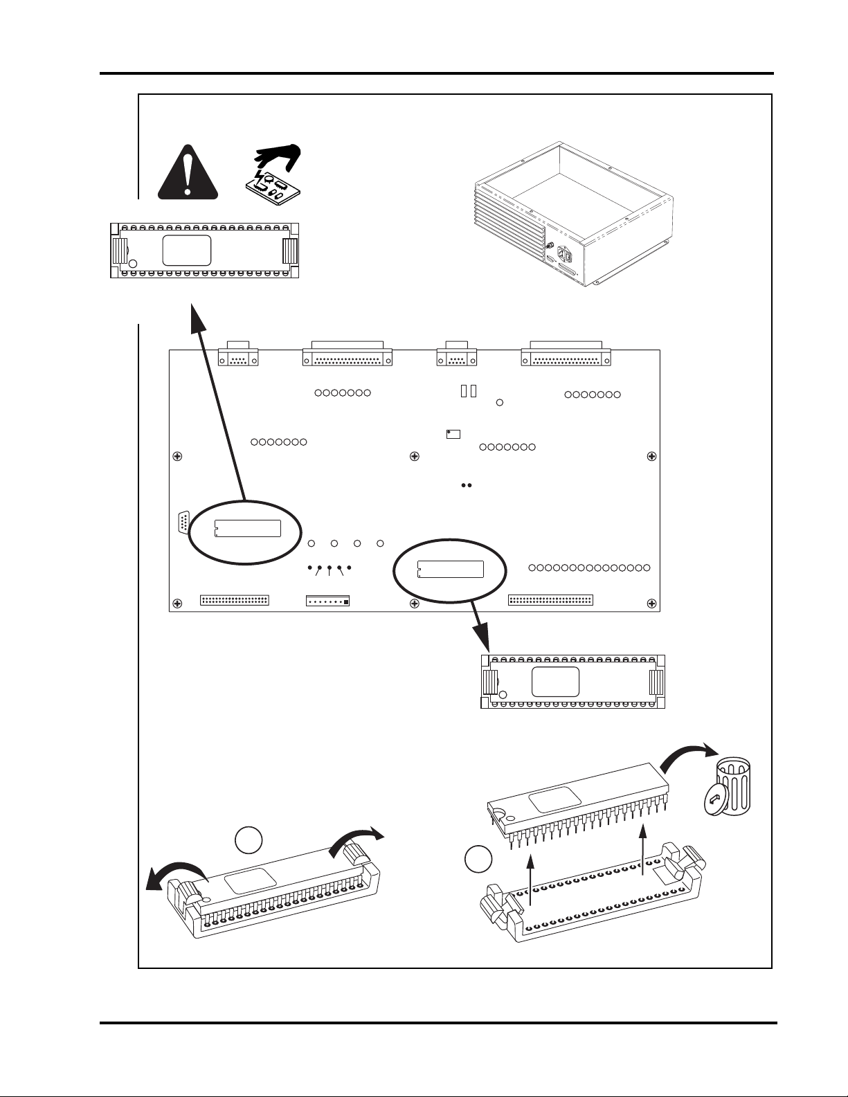
1. Turn off the power to the power supply.
2 Turn off the power to the THC system and remove power cord.
Plasma Interface Upgrade
2
1
3 Remove the THC control module cover.
3
IM380.02
128503 Kit Instructions
Page 3
Page 5
command THC
Plasma Interface Upgrade
4 Remove and discard the 2 microprocessors from the control PCB.
081030
Rev
INTERFACE MICROPROCESSOR
RS-422 MACHINE INTERFACE PENDANT PLASMA INTERFACE
P1
ARC VOLTAGE
ADJUST
J5
1
J10
J11
D16
G
PLASMA INTERFACE OUTPUTS
34 35 36 37
33
D32 38
PLASMA START OUT
HOLD IGNITION OUT
PIERCE COMPLETE OUT
EXT INTERLOCK OK
PLASMA SPARE OUT 1
J1
1
MACHINE INTERFACE OUTPUTS
27 28 29 30
26D9D25 31
RR RRRRY
MACH SPARE OUT 1
RETRACT COMPLETE
PILOT ARC OUT
THC ERROR OUT
MACH MOTION OUT
MACHINE INTERFACE INPUTS
10 11 12 13 14
CYCLE START IN
AUTO HEIGHT ON/OFF
IHS COMPLETE
ERROR #1
RESERVED 1
RESERVED 2
IHS SYNC IN
15
GGGGGGG
RESERVED 3
MACHINE CABLE
J4
1
YRRRRRR
PLASMA SPARE OUT 3
PLASMA SPARE OUT 2
ERROR #2
1
PLASMA INTERFACE INPUTS
18 19 20 21 22
D17
GG GGGGG
ALT-TORCH-IN-POS
ALT-TORCH-SEL-IN
TRANSFER IN
PILOT ARC IN
NOZZLE CONTACT IN
PLASMA SPARE IN 1
J6
23
PLASMA CABLE
J2
RS-232
DIAGNOSTIC PORT
1
1
U36
INTERFACE
MICROPROCESSOR
J3
EXPANSION PORT
1 1
GGGG
TP3
GND
TP4
+24V
J8 DC POWER IN
CONTROL PCB
D42 D43 D44D41
TP6
TP5
+12V
-12V
TP7
+5V
1
041507
+5V+12V-12V+24V
1
U48
REAL-TIME
MICROPROCESSOR
IM380.04
1
TP2
TP1
ERROR-RESOLUTION
SPEED-RESPONSE
D45 46 47 48 49 50 51 52 53 54 55 56
GGGGGGGGGGGGG
TO MOTOR DRIVE PCB
J7
081029
Rev
REAL TIME MICROPROCESSOR
2
MOTOR CURRENT CHECK
HOME POSITION SWITCH
ASYMETRIC-RESPONSE
LOWER LIMIT SWITCH
CRASH DETECT
MOTOR DRIVE INTERFACE
LIFTER SPARE IN 4
DRIVE ID 4
DRIVE ID 2
DRIVE ID 1
MOTOR DRIVE INSTALLED
LIFTER SPARE IN 5
ENCODER B
ENCODER A
58 5957
GG
128503 Kit Instructions
Page 4
Page 6

command THC
Plasma Interface Upgrade
5 Install the new microprocessors into the control PCB.
081030
Rev H
INTERFACE MICROPROCESSOR
RS-422 MACHINE INTERFACE PENDANT PLASMA INTERFACE
J1
1
MACHINE INTERFACE OUTPUTS
27 28 29 30
26D9D25 31
RR RRRRY
MACH SPARE OUT 1
RETRACT COMPLETE
PILOT ARC OUT
THC ERROR OUT
MACH MOTION OUT
MACHINE INTERFACE INPUTS
10 11 12 13 14
CYCLE START IN
AUTO HEIGHT ON/OFF
IHS COMPLETE
ERROR #1
RESERVED 1
RESERVED 2
IHS SYNC IN
15
GGGGGGG
RESERVED 3
MACHINE CABLE
J4
1
P1
ARC VOLTAGE
ADJUST
J5
1
J10
J11
D16
PLASMA INTERFACE OUTPUTS
33
D32 38
PLASMA START OUT
HOLD IGNITION OUT
EXT INTER-
G
LOCK OK
34 35 36 37
YRRRRRR
PLASMA SPARE OUT 3
PLASMA SPARE OUT 2
PIERCE COMPLETE OUT
PLASMA SPARE OUT 1
ERROR #2
1
PLASMA INTERFACE INPUTS
18 19 20 21 22
D17
GG GGGGG
TRANSFER IN
PILOT ARC IN
NOZZLE CONTACT IN
PLASMA SPARE IN 1
ALT-TORCH-IN-POS
ALT-TORCH-SEL-IN
J6
23
PLASMA CABLE
J2
RS-232
DIAGNOSTIC PORT
1
1
U36
INTERFACE
MICROPROCESSOR
J3
EXPANSION PORT
1 1
GGGG
TP3
GND
TP4
+24V
J8 DC POWER IN
IM380.01
Align the dot on the microprocessor
with the number 1 on the control PCB.
CONTROL PCB
D42 D43 D44D41
TP6
TP5
+12V
-12V
TP7
+5V
1
041507
+5V+12V-12V+24V
1
U48
REAL-TIME
TP2
MICROPROCESSOR
TP1
J7
HOME POSITION SWITCH
ASYMETRIC-RESPONSE
ERROR-RESOLUTION
SPEED-RESPONSE
CRASH DETECT
D45 46 47 48 49 50 51 52 53 54 55 56
GGGGGGGGGGGGG
MOTOR DRIVE INTERFACE
TO MOTOR DRIVE PCB
081029
Rev H
REAL TIME MICROPROCESSOR
MOTOR CURRENT CHECK
LOWER LIMIT SWITCH
LIFTER SPARE IN 4
DRIVE ID 2
DRIVE ID 1
MOTOR DRIVE INSTALLED
LIFTER SPARE IN 5
ENCODER A
DRIVE ID 4
58 5957
ENCODER B
GG
128503 Kit Instructions
Page 5
Page 7
command THC
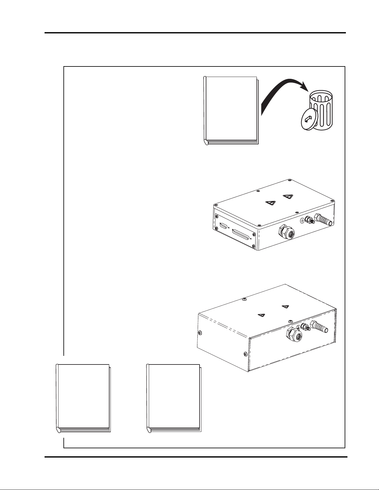
6. Before removing the old plasma interface assembly, mark all of the wire connections so that they can
be reinstalled correctly.
7 Discard your existing Command THC
Instruction Manual.
Plasma Interface Upgrade
802510
OR
802780
Command THC
Instruction Manual
Revisions 1 thru 4
8 Remove the old interface assembly.
9 Install the new interface assembly per the
revised instruction manual included with
this kit.
802780
X-Y
Command THC
Instruction Manual
- OR -
802510
Robotic
Command THC
Instruction Manual
IM308.06
128503 Kit Instructions
Page 6
Page 8
command THC
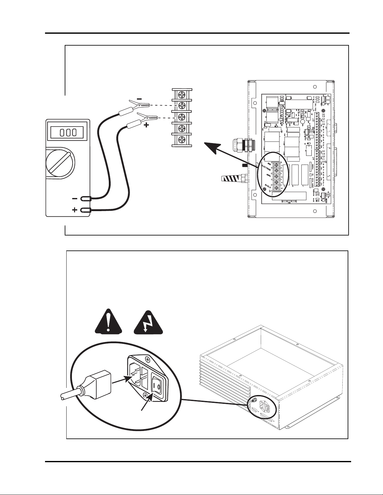
10 Attach the volt meter to measure the arc voltage between J5-2 and J5-3 in the plasma interface
assembly.
Plasma Interface Upgrade
GND
ELECTRODE
WORK
J5
11 Replace the power cord to the THC control module.
12345
THC.91
12 Turn on the power to the THC.
13 Turn on the power to the power supply.
IM380.03
128503 Kit Instructions
Page 7
Page 9

command THC
IM380.08
14. Put the Command THC in MANUAL MODE.
15. Begin a cutting process and compare the voltage displayed on the volt meter to the arc voltage
displayed on the CNC or THC pendant.
16 Adjust the potentiometer on the PC board so that the
voltage displayed on the volt meter is the same as the arc
voltage displayed on the CNC or THC pendant.
Plasma Interface Upgrade
IM380.07
17. Turn off power to power supply and to THC system.
18. Remove volt meter from the plasma interface assembly.
19 Install the access cover to the
THC plasma interface assembly
and the control module.
128503 Kit Instructions
Page 8
 Loading...