

Page 1
®
THC.14
command THC
Control PC Board
Replacement and Calibration
Kit 128407
Kit Instructions
803600 - Revision 2
Page 2

command THC
Control PC Board Replacement
and
Calibration
Kit 128407
Kit Instructions
IM-360
(P/N 803600)
Revision 2 - April 2000
Hypertherm, Inc.
Hanover, NH USA
http://www.hypertherm.com
email: info@hypertherm.com
© Copyright 2000 Hypertherm, Inc.
All Rights Reserved
Hypertherm and Command THC are trademarks of Hypertherm, Inc. and may be
registered in the United States and/or other countries.
Page 3

Hypertherm Offices Worldwide
Hypertherm, Inc.
Etna Road, P.O. Box 5010
Hanover, NH 03755 USA
Tel.: (603) 643-3441 (Main Office)
Fax: (603) 643-5352 (All Departments)
Tel.: (800) 643-9878 (Technical Service – toll-free in USA and Canada)
Tel.: (800) 737-2978 (Customer Service – toll-free in USA and Canada)
email: info@hypertherm.com (General Information)
email: service@hypertherm.com (Technical/Customer Services)
Hypertherm Plasmatechnik GmbH
Technologiepark Hanau
Rodenbacher Chaussee 6
D–63457 Hanau-Wolfgang, Germany
Tel.: 49 6181 58 2100
Fax: 49 6181 58 2134
Hypertherm (S) Pte Ltd
No. 19 Kaki Bukit Road 2
K.B. Warehouse Complex
Singapore 417847
Tel.: 65 841 2489
Fax: 65 841 2490
Hypertherm UK Ltd
9 Berkeley Court, Manor Park
Runcorn, Cheshire, England WA7 1TQ
Tel.: 44 1928 579 074
Fax: 44 1928 579 604
:
France
15 Impasse des Rosiers
95610 Eragny, France
Tel.: 33 1 30 37 15 28
Fax: 33 1 30 37 15 79
Hypertherm S.r.L.
Via Torino 2
20123 Milan, Italy
Tel.: 39 02 725 46 312 (Customer Service)
Tel.: 39 02 725 46 314 (Technical Service)
Fax: 39 02 725 46 400 (All Departments)
Hypertherm B.V.
Burg, Haverkampstraat 13
7091 CN Dinxperlo, The Netherlands
Tel.: 31 315 655 866 (Customer Service)
Fax: 31 315 655 886
European Technical Support Organization (ETSO)
Edisonstraat 12
3281 NC Numansdorp, The Netherlands
Tel.: +800 4973 7843 (+800 Hypertherm) – (toll-free Technical Service)
Tel.: 31 186 659494
Fax: 31 186 659495
Japan
Shinjuku Park Tower
30th Floor
3-7-1 Nishi-Shinjuku
Shinjuku-ku, Tokyo
163-1030, Japan
Tel.: 81 03 5326 3142
Fax: 81 03 5326 3001
3/00
Page 4

Command THC Control PC Board Calibration
In This Bulletin:
128407 KIT CONTENTS ........................................................................................................... Page 2
PURPOSE................................................................................................................................. Page 2
REQUIREMENTS ..................................................................................................................... Page 3
Tools Needed .........................................................................................................................Page 3
HD4070 PROCEDURE .............................................................................................................Page 4
HT4400 PROCEDURE ............................................................................................................. Page 6
POWERMAX, MAX100, MAX200, HD3070, HT2000,
HT2000LHF, AND HT4001 PROCEDURE............................................................................. Page 8
128407 Kit Instructions
Page 1
Page 5

Command THC Control PC Board Calibration
128407 KIT CONTENTS
041507 Control Module PC Board
803600 Instructions
PURPOSE
After installing the replacement PC board included with this kit, calibration of the THC system is required.
These instructions provide calibration procedures.
Page 2
128407 Kit Instructions
Page 6
Command THC Control PC Board Calibration
REQUIREMENTS
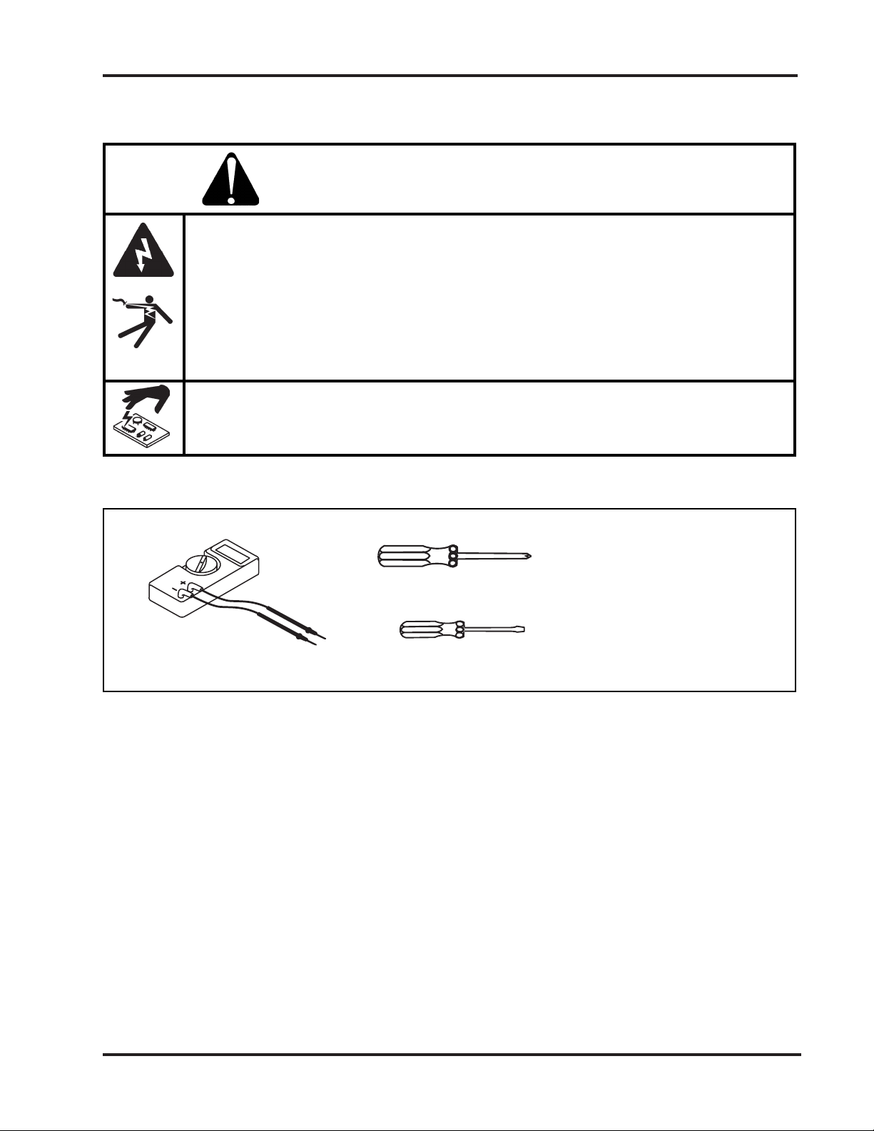
ELECTRIC SHOCK CAN KILL
• Turn off the power and remove the input power plug from its receptacle before
removing any access cover. If the power supply is directly connected to a line
disconnect box, switch the line disconnect to OFF (O). In the U.S., use a "lock-out
/ tag-out" procedure until the service or maintenance work is complete. In other
countries, follow appropriate national or local safety procedures.
• Do not touch live electrical parts! If power is required for servicing, use extreme
caution when working near live electrical circuits. Dangerous voltages exist inside
the THC control module that can cause serious injury or death.
STATIC ELECTRICITY CAN DAMAGE CIRCUIT BOARDS
• Put on a grounded wrist strap BEFORE handling PC boards.
WARNING
Tools Needed
Digital Volt Meter
#2 Phillips Screw Driver
Small, Flat Screw Driver
128407 Kit Instructions
Page 3
Page 7

THC.108
HD4070 THC Control PC Board Calibration
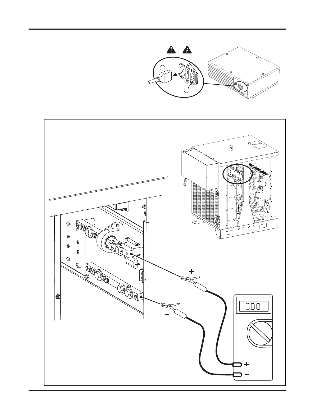
HD4070 PROCEDURE
1. Turn off the power to the power supply.
2. Install the replacement PC board in to the power supply and attach all electrical connections.
3 Attach the volt meter to measure the arc voltage between power supply I/O board bus bars as shown
below.
Page 4
Set volt meter to
measure 100-500 VDC.
128407 Kit Instructions
Page 8

HD4070 THC Control PC Board Calibration
THC.107
Torch #1
THC Control
PC Board
Torch #2
THC Control
PC Board
4. Turn on power to the power supply.
5. Put the Command THC in MANUAL MODE.
6. For 2-torch systems, select the applicable torch.
7. Begin a cutting process and compare the voltage displayed on the volt meter to the arc voltage
displayed on the CNC or power supply display.
8 Adjust the potentiometer on the control board so that the voltage displayed on the volt meter is the
same as the arc voltage displayed on the CNC or power supply display.
9. Turn off the power to the power supply.
10. Remove the volt meter from the power supply.
11. Replace the access covers to the power supply.
128407 Kit Instructions
Page 5
Page 9
HT4400 THC Control PC Board Calibration
THC.109
IM379.01
1
2
HT4400 PROCEDURE
1. Turn off the power to the THC control
module and to the power supply.
2. Install the replacement PC board in to the THC control module and attach the electrical connections.
3 Attach the volt meter to measure the arc voltage between power supply I/O board bus bars as shown
below.
Page 6
Set volt meter to
measure 100-500 VDC.
128407 Kit Instructions
Page 10

IM360.02
HT4400 THC Control PC Board Calibration
4. Turn on the power to the THC control module and to the power supply.
5. Put the Command THC in MANUAL MODE.
6. Begin a cutting process and compare the voltage displayed on the volt meter to the arc voltage
displayed on the CNC or THC pendant.
7 Adjust the potentiometer on the control board so that the voltage displayed on the volt meter is the
same as the arc voltage displayed on the CNC or THC pendant.
8. Turn off the power to the THC control module and to the power supply.
9. Remove the volt meter from the power supply.
10. Replace the access covers to the THC control module and to the power supply.
128407 Kit Instructions
Page 7
Page 11

THC.91
GND
ELECTRODE
WORK
J5
12345
IM360.01
IM379.01
1
2
Powermax, MAX100, MAX200, HD3070, HT2000,
HT2000LHF, and HT4001 THC Control PCB Calibration
POWERMAX, MAX100, MAX200,
HD3070, HT2000, HT2000LHF, AND
HT4001 PROCEDURE
1. Turn off the power to the power supply.
2. Turn off power to THC system
and remove power cord.
3 Remove access covers from the THC control
module and the THC plasma interface assembly.
4. Install the replacement PC board in to the THC control module and attach electrical connections.
5 Attach the volt meter to measure the arc voltage between J5-2 and J5-3 in the plasma interface
assembly.
Set volt meter to
measure 100-500 VDC.
Page 8
128407 Kit Instructions
Page 12

IM360.02
Powermax, MAX100, MAX200, HD3070, HT2000,
HT2000LHF, and HT4001 THC
6. Replace power cord to the THC control module.
7. Turn on power to the THC and to the power supply.
8. Put the Command THC in MANUAL MODE.
9. Begin a cutting process and compare the voltage displayed on the volt meter to the arc voltage
displayed on the CNC or THC pendant.
10 Adjust the potentiometer on the control board so that the voltage displayed on the volt meter is the
same as the arc voltage displayed on the CNC or THC pendant.
Control PCB Calibration
11. Turn off power to power supply and to THC system.
12. Remove volt meter from the plasma interface assembly.
13. Replace access covers to the THC control module and the THC plasma interface assembly.
128407 Kit Instructions
Page 9
Page 13

Blank
Page 10
128407 Kit Instructions
 Loading...