

Page 1

THC-2
Torch Height Control
Instruction Manual
800200 Rev. 6
Page 2

THC-2
Torch Height Control
Instruction Manual
P/N 800200
Revision 6 September, 2002
Hypertherm, Inc.
Hanover, NH USA
www.hypertherm.com
© Hypertherm, Inc., 2002
All Rights Reserved
HYPERTHERM is a trademark of Hypertherm, Inc. and is
registered in the United States; International registration is pending.
Page 3

Hypertherm, Inc.
Etna Road, P.O. Box 5010
Hanover, NH 03755 USA
603-643-3441 Tel (Main Office)
603-643-5352 Fax (All Departments)
800-643-9878 Tel (Technical Service)
800-737-2978 Tel (Customer Service)
Hypertherm Automation
5 Technology Drive
West Lebanon, NH 03755 USA
603-298-7970 Tel
603-298-7977 Fax
Hypertherm Plasmatechnik GmbH
Technologiepark Hanau
Rodenbacher Chaussee 6
63457 Hanau-Wolfgang, Deutschland
49 6181 58 2100 Tel
49 6181 58 2134 Fax
49 6181 58 2123 (Technical Service)
Hypertherm Singapore Pte Ltd
No. 19 Kaki Bukit Road 2
K.B. Warehouse Complex
Singapore 417847, Republic of Singapore
65 841 2489 Tel
65 841 2490 Fax
65 841 2489 (Technical Service)
Japan
1952-14 Yata-Natsumegi
Mishima City, Shizuoka Pref.
411-0801 Japan
81 0 559 75 7387 Tel
81 0 559 75 7376 Fax
Hypertherm UK Ltd
9 Berkeley Court, Manor Park
Runcorn, Cheshire, England WA7 1TQ
44 1928 579 074 Tel
44 1928 579 604 Fax
France
15 Impasse des Rosiers
95610 Eragny, France
0805 050 111 Tel
0805 050 222 Fax
Hypertherm S.r.L.
Via Torino 2
20123 Milano, Italia
39 02 725 46 312 Tel
39 02 725 46 400 Fax
39 02 725 46 314 (Technical Service)
Hypertherm B.V.
Burg. Haverkampstraat 13
7091 CN Dinxperlo, Nederland
31 315 655866 Tel
31 315 655886 Fax
Hypertherm B.V. (ETSO)
Vaartveld 9
4704 SE Roosendaal, Nederland
00 800 49 73 7843 – toll-free in Europa
31 165 596900 Tel
31 165 596901 Fax
Hypertherm Brasil Ltda.
Rua Visconde de Santa Isabel, 20 – Sala 611
Vila Isabel, RJ
Brasil CEP 20560-120
55 21 2278 6162 Tel
55 21 2578 0947 Fax
10/30/01
Page 4

ELECTROMAGNETIC COMPATIBILITY (EMC)
EMC INTRODUCTION
Hypertherm's CE-marked equipment is built
in compliance with standard EN50199. The
equipment should be installed and used in
accordance with the information below to
achieve electromagnetic compatibility.
The limits required by EN50199 may not be
adequate to completely eliminate interference when the affected equipment is in
close proximity or has a high degree of
sensitivity. In such cases it may be necessary to use other measures to further
reduce interference.
This plasma equipment is designed for use
only in an industrial environment.
INSTALLATION AND USE
The user is responsible for installing and
using the plasma equipment according to
the manufacturer's instructions. If electromagnetic disturbances are detected then it
shall be the responsibility of the user to resolve the situation with the technical assistance of the manufacturer. In some cases
this remedial action may be as simple as
earthing the cutting circuit, see Earthing of
Workpiece. In other cases it could involve
constructing an electromagnetic screen
enclosing the power source and the work
complete with associated input filters. In all
cases electromagnetic disturbances must
be reduced to the point where they are no
longer troublesome.
ASSESSMENT OF AREA
Before installing the equipment the user
shall make an assessment of potential electromagnetic problems in the surrounding
area. The following shall be taken into
account:
a. Other supply cables, control cables,
signalling and telephone cables; above,
below and adjacent to the cutting equipment.
b. Radio and television transmitters and
receivers.
c. Computer and other control equipment.
d. Safety critical equipment, for example
guarding of industrial equipment.
e. Health of the people around, for
example the use of pacemakers and hearing aids.
f. Equipment used for calibration or measurement.
g. Immunity of other equipment in the environment. User shall ensure that other
equipment being used in the environment is
compatible. This may require additional
protection measures.
h. Time of day that cutting or other activities
are to be carried out.
Earthing of Workpiece
Where the workpiece is not bonded to earth
for electrical safety, nor connected to earth
because of its size and position, for example,
ship's hull or building steelwork, a connection
bonding the workpiece to earth may reduce
emissions in some, but not all instances.
Care should be taken to prevent the earthing
of the workpiece increasing the risk of injury
to users, or damage to other electrical equipment. Where necessary, the connection of
the workpiece to earth should be made by a
direct connection to the workpiece, but in
some countries where direct connection is
not permitted, the bonding should be
achieved by suitable capacitances selected
according to national regulations.
Note. The cutting circuit may or may not be
earthed for safety reasons. Changing the
earthing arrangements should only be authorized by a person who is competent to
assess whether the changes will increase
the risk of injury, for example, by allowing
parallel cutting current return paths which
may damage the earth circuits of other
equipment. Further guidance is given in IEC
TC26 (sec)94 and IEC TC26/108A/CD Arc
Welding Equipment Installation and Use.
Screening and Shielding
Selective screening and shielding of other
cables and equipment in the surrounding
area may alleviate problems of interference.
Screening of the entire plasma cutting
installation may be considered for special
applications
The size of the surrounding area to be
considered will depend on the structure of
the building and other activities that are taking place. The surrounding area may extend
beyond the boundaries of the premises.
METHODS OF REDUCING EMISSIONS
Mains Supply
Cutting equipment must be connected to the
mains supply according to the manufacturer's recommendations. If interference
occurs, it may be necessary to take
additional precautions such as filtering of
the mains supply. Consideration should be
given to shielding the supply cable of permanently installed cutting equipment, in
metallic conduit or equivalent. Shielding
should be electrically continuous throughout
its length. The shielding should be connected to the cutting mains supply so that good
electrical contact is maintained between the
conduit and the cutting power source
enclosure
Maintenance of Cutting Equipment
The cutting equipment must be routinely
maintained according to the manufacturer's
recommendations. All access and service
doors and covers should be closed and
properly fastened when the cutting
equipment is in operation. The cutting
equipment should not be modified in any
way except for those changes and adjustments covered in the manufacturer's
instructions. In particular, the spark gaps of
arc striking and stabilizing devices should
be adjusted and maintained according to
the manufacturer's recommendations.
Cutting Cables
The cutting cables should be kept as short
as possible and should be positioned close
together, running at or close to the floor
level.
Equipotential Bonding
Bonding of all metallic components in the
cutting installation and adjacent to it should
be considered. However, metallic components bonded to the workpiece will increase
the risk that the operator could receive a
shock by touching these metallic
components and the electrode at the same
time. The operator should be insulated from
all such bonded metallic components.
Hypertherm Plasma Systems i
Page 5

WARRANTY
ii Hypertherm Plasma Systems
9-01
WARNING
Genuine Hypertherm parts are the factory-recommended
replacement parts for your Hypertherm system. Any damage
caused by the use of other than genuine Hypertherm parts may
not be covered by the Hypertherm warranty.
WARNING
You are responsible for the safe use of the Product.
Hypertherm does not and cannot make any guarantee or
warranty regarding the safe use of the Product in your
environment.
GENERAL
Hypertherm, Inc. warrants that its Products shall be free from
defects in materials and workmanship, if Hypertherm is notified
of a defect (i) with respect to the power supply within a period
of two (2) years from the date of its delivery to you, with the
exception of G3 Series power supplies, which shall be within a
period of three (3) years from the date of delivery to you, and
(ii) with respect to the torch and leads within a period of one (1)
year from its date of delivery to you. This warranty shall not
apply to any Product which has been incorrectly installed,
modified, or otherwise damaged. Hypertherm, at its sole
option, shall repair, replace, or adjust, free of charge, any
defective Products covered by this warranty which shall be
returned with Hypertherm’s prior authorization (which shall not
be unreasonably withheld), properly packed, to Hypertherm’s
place of business in Hanover, New Hampshire, or to an
authorized Hypertherm repair facility, all costs, insurance and
freight prepaid. Hypertherm shall not be liable for any repairs,
replacement, or adjustments of Products covered by this
warranty, except those made pursuant to this paragraph or with
Hypertherm’s prior written consent. The warranty above is
exclusive and is in lieu of all other warranties, express,
implied, statutory, or otherwise with respect to the
Products or as to the results which may be obtained
therefrom, and all implied warranties or conditions of
quality or of merchantability or fitness for a particular
purpose or against infringement. The foregoing shall
constitute the sole and exclusive remedy for any breach
by Hypertherm of its warranty. Distributors/OEMs may offer
different or additional warranties, but Distributors/OEMs are
not authorized to give any additional warranty protection to you
or make any representation to you purporting to be binding
upon Hypertherm.
PATENT INDEMNITY
Except only in cases of products not manufactured by
Hypertherm or manufactured by a person other than
Hypertherm not in strict conformity with Hypertherm’s
specifications and in cases of designs, processes, formulae, or
combinations not developed or purported to be developed by
Hypertherm, Hypertherm will defend or settle, at its own
expense, any suit or proceeding brought against you alleging
that the use of the Hypertherm product, alone and not in
combination with any other product not supplied by
Hypertherm, infringes any patent of any third party. You shall
notify Hypertherm promptly upon learning of any action or
threatened action in connection with any such alleged
infringement, and Hypertherm’s obligation to indemnify shall be
conditioned upon Hypertherm’s sole control of, and the
indemnified party’s cooperation and assistance in, the defense
of the claim.
LIMITATION OF LIABILITY
In no event shall Hypertherm be liable to any person or
entity for any incidental, consequential, indirect, or
punitive damages (including but not limited to lost profits)
regardless of whether such liability is based on breach of
contract, tort, strict liability, breach of warranties, failure of
essential purpose or otherwise and even if advised of the
possibility of such damages.
LIABILITY CAP
In no event shall Hypertherm’s liability, whether such
liability is based on breach of contract, tort, strict liability,
breach of warranties, failure of essential purpose or
otherwise, for any claim action suit or proceeding arising
out of or relating to the use of the Products exceed in the
aggregate the amount paid for the Products that gave rise
to such claim.
INSURANCE
At all times you will have and maintain insurance in such
quantities and types, and with coverage sufficient and
appropriate to defend and to hold Hypertherm harmless in
the event of any cause of action arising from the use of the
Products.
NATIONAL AND LOCAL CODES
National and Local codes governing plumbing and electrical
installation shall take precedent over any instructions
contained in this manual. In no event shall Hypertherm be
liable for injury to persons or property damage by reason of any
code violation or poor work practices.
TRANSFER OF RIGHTS
You may transfer any remaining rights you may have
hereunder only in connection with the sale of all or substantially
all of your assets or capital stock to a successor in interest who
agrees to be bound by all of the terms and conditions of this
Warranty.
Page 6

TABLE OF CONTENTS
DESCRIPTION AND SPECIFICATIONS .................................................................. v
SECTION 1 INSTALLATION - To Cutting Machine and Torch Lifter ..................1-1
Install the THC-2 Control Module ...........................................................................1-2
Mount the THC-2 Control Module .....................................................................1-2
Connect the THC-2 Control Module to the Cutting Machine
Computer Interface and Torch Lifter Motor .......................................................1-3
SECTION 1a INSTALLATION - MAX100 or MAX100D ...................................... 1a-1
Mount the Voltage Divider to MAX100 or MAX100D ............................................ 1a-2
Install Interconnect Cable to MAX100 or MAX100D .............................................1a-2
SECTION 1b INSTALLATION - MAX200 ...........................................................1b-1
Mount the Voltage Divider to MAX200 .................................................................1b-2
Install Interconnect Cable to MAX200 ..................................................................1b-4
SECTION 1c INSTALLATION - PAC-500 .......................................................... 1c-1
Mount the Voltage Divider to PAC-500................................................................. 1c-2
Install Interconnect Cable to PAC-500 .................................................................1c-3
SECTION 2 OPERATION ..................................................................................2-1
Description of Controls and Indicators ...................................................................2-2
Operating Instructions ............................................................................................2-3
Notes on Operation...........................................................................................2-3
SECTION 3 PARTS LIST...................................................................................3-1
THC-2 Torch Height Control Systems ....................................................................3-2
Torch Height Control System for MAX100, MAX100D, MAX200....................... 3-2
Torch Height Control System for PAC-500 .......................................................3-2
THC-2 Interconnect Cable - #023264 ....................................................................3-3
THC-2 Control Module - #053005 ..........................................................................3-5
THC-2 Torch Height Control
Page iii
Page 7

TABLE OF CONTENTS
List of Figures
Figure 1-1 THC-2 Control Module Mounting Dimensions....................................................... 1-2
Figure 1-2 THC-2 Control Module Front and Rear Views ...................................................... 1-3
Figure 1-3 Wiring Diagram -
THC-2 to Cutting Machine Interface and Lifter Motor ........................................... 1-4
Figure 1-4 Typical DC Lifter Wiring ........................................................................................ 1-5
Figure 1a-1 Connections to MAX100 or MAX100D ................................................................. 1a-3
Figure 1b-1 Voltage Divider Template Location -
MAX200 Center Wall Right Rear ........................................................................ 1b-3
Figure 1b-2 Voltage Divider Mounting Location -
MAX200 Center Wall Left Rear ........................................................................... 1b-3
Figure 1b-3 Inside Rear of MAX200 Power Supply ................................................................ 1b-4
Figure 1b-4 Wiring Diagram - THC-2 to MAX200 ................................................................... 1b-5
Figure 1c-1 PAC-500 Plasma Control Console Plumbing Compartment ................................ 1c-2
Figure 1c-2 PAC-500/500L Plasma Control Consoles ............................................................ 1c-3
Figure 1c-3 PAC-500/500L Plasma Control Consoles - 1TB Location .................................... 1c-4
Figure 1c-4 HF Compartment - PAC-500 Console .................................................................. 1c-5
Figure 1c-5 Top Rear View of THC-2 ......................................................................................1c-6
Figure 1c-6 Inside View of THC-2 ........................................................................................... 1c-7
Figure 2-1 THC-2 Front Panel ................................................................................................ 2-2
Figure 3-1 THC-2 Control Cable - MAX100/100D/200 ............................................................ 3-3
Figure 3-2 THC-2 Front and Rear Panels .............................................................................. 3-4
Figure 3-3 THC-2 Interior ....................................................................................................... 3-6
FIgure 3-4 Voltage Divider - 041007 - .................................................................................... 3-8
Page iv
THC-2 Torch Height Control
Page 8

DESCRIPTION AND SPECIFICATIONS
DESCRIPTION
he THC-2 Torch Height Control automatically controls torch height while plasma cutting. After
setting the arc voltage with the thumbwheel on the front panel, the THC-2 controls the torch
T
the workpiece. If the torch is too high from the workpiece, the actual arc voltage will be greater than
the reference voltage. The Arc Voltage Control will then activate the torch suspension motor to move
the torch downward. If the torch is too close to the workpiece, the arc voltage will be less than the
reference voltage. In this case, the Arc Voltage Control will activate the torch suspension motor to
move the torch upward.
The THC-2 comes with a voltage divider that mounts in the MAX100 , MAX100D and MAX200 power
supplies, or in the PAC-500/500L Plasma Control Console. The voltage divider reduces the arc
voltage by a ratio of 25:1.
Section 1 of this manual - Installation - describes mounting the THC-2 module and connecting it to
the cutting machine computer and the torch lifter. Sub-sections 1a, 1b etc. describe hooking the
THC-2 to Hypertherm products that utilize this type of torch-height control. Section 2 is a brief
operation section, and Section 3 is a parts list. A wiring diagram follows the parts list.
suspension motor by comparing this reference voltage with the voltage between the torch and
SPECIFICATIONS
THC-2 Control Module - #053005*
Power Input .........................................................115 VAC, 50/60 Hz
Operating Environment ....................................... 32°F (0°C) to 122°F (50°C)
Height .................................................................. 6 inches (152 mm)
Width ...................................................................8 inches (203 mm)
Depth................................................................... 17 inches (432 mm)
Weight .................................................................15 pounds (6.8 kg)
Arc Voltage Setting Range .................................. 100-250 V
Control Accuracy ................................................. +/- 2 V
* For a parts list breakdown of the THC-2 systems see Section 3 - Parts List
THC-2 Torch Height Control
Page v
Page 9

Section 1 INSTALLATION - To Cutting Machine and
Torch Lifter
In this section:
Install the THC-2 Control Module........................................................1-2
Mount the THC-2 Control Module...................................................1-2
Connect the THC-2 Control Module to the Cutting Machine
Computer Interface and Torch Lifter Motor.....................................1-3
THC-2 Torch Height Control
Page 1-1
Page 10
INSTALLATION - To Cutting Machine & Torch Lifter
INSTALL THE THC-2 CONTROL MODULE
Before installing the THC-2 system, verify the following components after unpacking:
• Voltage Divider
• THC-2 Control Module
• Interconnecting cable #023264 (Cable not available for PAC-500 systems)
Mount the THC-2 Control Module
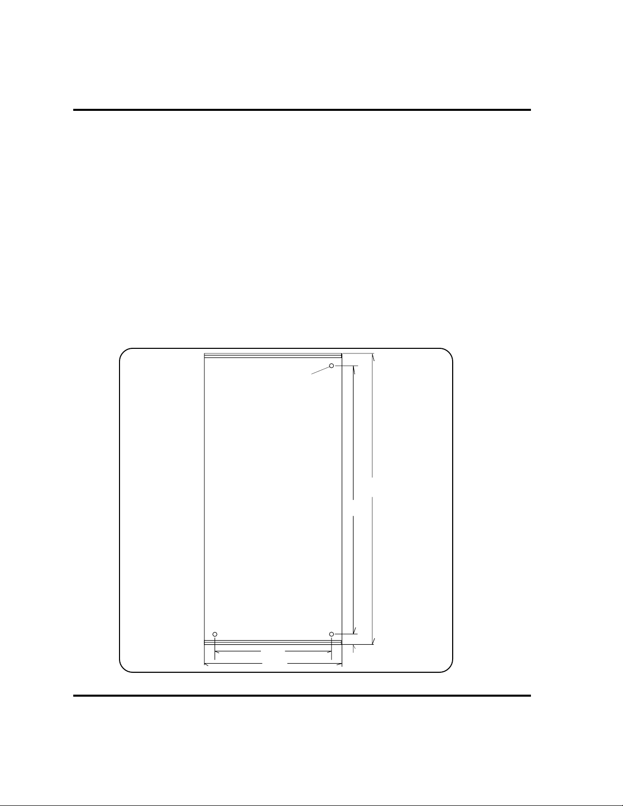
1. Mount the THC-2 Control Module in a convenient location for the operator. See Fig.1-1
for mounting dimensions. Note the length of the control cable (5 feet) that will connect
from the THC-2 to the inside of the MAX100, MAX100D, or MAX200 and make certain
that the cable will reach before mounting. Customers must supply and fabricate cables
for the PAC-500 systems.
8-32
Tapped
Hole (3)
Page 1-2
Bottom
View
FRONT
6-3/4"
8"
Figure 1-1 THC-2 Control Module Mounting Dimensions
17-3/32"
15-5/8"
5/8"
THC-2 Torch Height Control
Page 11

INSTALLATION - To Cutting Machine & Torch Lifter
2. To ensure proper grounding at the THC-2, run a #10 gauge copper cable from the ground
stud on the rear of the THC-2 (Fig. 1-2) to a common earth ground. To correctly operate
the THC-2 system, it must be grounded properly.
Connect the THC-2 Control Module to the Cutting Machine Computer Interface
and Torch Lifter Motor
A cable running from the THC-2 control module to the cutting machine interface and torch
lifter must be fabricated. Hypertherm recommends a 7-conductor 24-gauge shielded cable.
3. Remove the eight screws on the THC-2 Control Module and take off the top
panel - Fig. 1-2.
Remove Screws
Figure 1-2 THC-2 Control Module Front and Rear Views
THC-2 Torch Height Control
Remove Screws
RECP2
Ground
Stud
Strain
Reliefs
Page 1-3
Page 12

INSTALLATION - To Cutting Machine & Torch Lifter
4. Feed the cable through one of the strain reliefs located on the THC-2 rear panel (Fig.
1-2). See Figure 1-3 for cable connections. Consult your cutting machine schematics, or
call the cutting machine manufacturer for actual connections on the cutting machine
interface.
Note: The THC-2 normally operates AC lifter motors. See Figure 1-4 and refer to THC-2
schematic for DC lifter connections.
This completes installation of THC-2 to the cutting machine interface and torch lifter. For
installation of voltage divider and cable to: MAX100 or MAX100D - go to Section 1a;
MAX200 - go to Section 1b; PAC-500 - go to Section 1c.
1TB
Cutting Machine
Interface
Start*
Machine Motion**
AVC***
AC Lift Motor
UP
120
Common
DOWN
120 VAC Hot for
AC Lift Motor
Notes: * Not used for the PAC-500 system
** Dry contacts to CNC control. Closed = Motion; Open = No Motion
*** Dry contacts to CNC control. Closed = AVC allowed; Open = No AVC
127
128
129
130
131
132
133
126
119
THC-2
Figure 1-3 Wiring Diagram - THC-2 to Cutting Machine Interface and Lift Motor
Page 1-4
THC-2 Torch Height Control
Page 13
INSTALLATION - To Cutting Machine & Torch Lifter
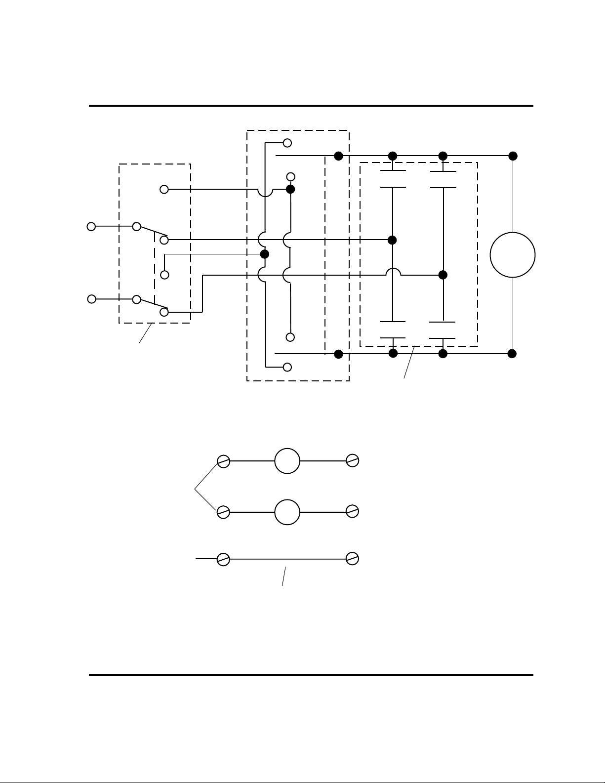
UP
DOWN
DN
MAN
+
UP
DC
Power
_
AUTO
MAN
AUTO
Double pole, single throw
toggle switch - Mount in
operator station
Jump to wire 106
on DC Power Supply
1PS in THC-2
UP
115VAC
DN
115VAC
UP
DOWN
UP
Quantity (2), 2 pole, N/O relays,
115 VAC coils - Mount in the THC-2
1TB-131
1TB-133
DN
Lifter
Motor
Jump to wire 107
on DC Power Supply
1PS in THC-2
Add jumper and relays to THC-2
Figure 1-4 Typical DC Lifter Wiring
THC-2 Torch Height Control
JUMPER
1TB-132
Page 1-5
Page 14

Section 1a INSTALLATION - MAX100 or MAX100D
In this section:
Mount the Voltage Divider to MAX100 or MAX100D ........................1a-2
Install Interconnect Cable to MAX100 or MAX100D .........................1a-2
THC-2 Torch Height Control
Page 1a-1
Page 15

INSTALLATION - MAX100 or MAX100D
MOUNT THE VOLTAGE DIVIDER TO MAX100 OR MAX100D
Be sure to complete all steps in Section 1: Installation - To Cutting Machine & Torch Lifter in addition to the following procedure for hooking the THC-2 to the MAX100 or MAX100
WARNING!
The line disconnect switch for the MAX100 / MAX100D must be in the OFF
position before proceeding with the installation of the voltage divider and
interconnect cable.
1. Remove the four screws on the rear of the voltage divider, but do not remove the cover.
2. Remove the left cover on the MAX100 or MAX100D power supply.
3. Place the voltage divider on the upper inside of the rear wall, lining up the screw holes of
the voltage divider with slots in the rear panel. (Be certain that the white wire from the
voltage divider reaches the terminal strip TB1.) Secure with the four screws.
D.
4. Connect the white wire on the voltage divider labeled "39" to wire labeled 39 on
TB1 - Fig. 1a-1.
INSTALL INTERCONNECT CABLE TO MAX100 OR MAX100D
1. Attach the connector end of the interconnect cable to the receptacle on the rear of the
THC-2 module (RECP2).
2. Feed the other end of the cable through the strain relief at the lower rear of the
MAX100 or MAX100D power supply and make connections to TB1 as in Figure 1a-1.
3. Connect a 24-gauge wire from TB1 - 70 to SIGNAL on the voltage divider - Fig. 1a-1.
Note: The 24-gauge wire is not supplied by Hypertherm.
4. Connect a 24-gauge wire from TB1 - 42 to GROUND on the voltage divider - Fig. 1a-1.
Note: The 24-gauge wire is not supplied by Hypertherm.
This completes installation of the THC-2 to the MAX100 or MAX100D. See Section 2 for
operation instructions.
Page 1a-2
THC-2 Torch Height Control
Page 16
Voltage
Divider
INSTALLATION - MAX100 or MAX100D
GROUND
SIGNAL
MAX100 or MAX100D Harness
1
2
4239
33 37 38
34
35 36
TB1
391234
42
33
Interconnect Cable
35 36 70
Figure 1a-1 Connections to MAX100 or MAX100D
THC-2 Torch Height Control
Page 1a-3
Page 17

Section 1b INSTALLATION - MAX200
In this section:
Mount the Voltage Divider to MAX200 .............................................1b-2
Install Interconnect Cable to MAX200 .............................................. 1b-4
THC-2 Torch Height Control
Page 1b-1
Page 18
INSTALLATION - MAX200
MOUNT THE VOLTAGE DIVIDER TO MAX200
Be sure to complete all steps in Section 1: Installation - To Cutting Machine & Torch Lifter in addition to the following procedure for hooking the THC-2 to the MAX200.
WARNING!
The line disconnect switch for the MAX200 must be in the OFF position
before proceeding with the installation of the voltage divider and interconnect
cable.
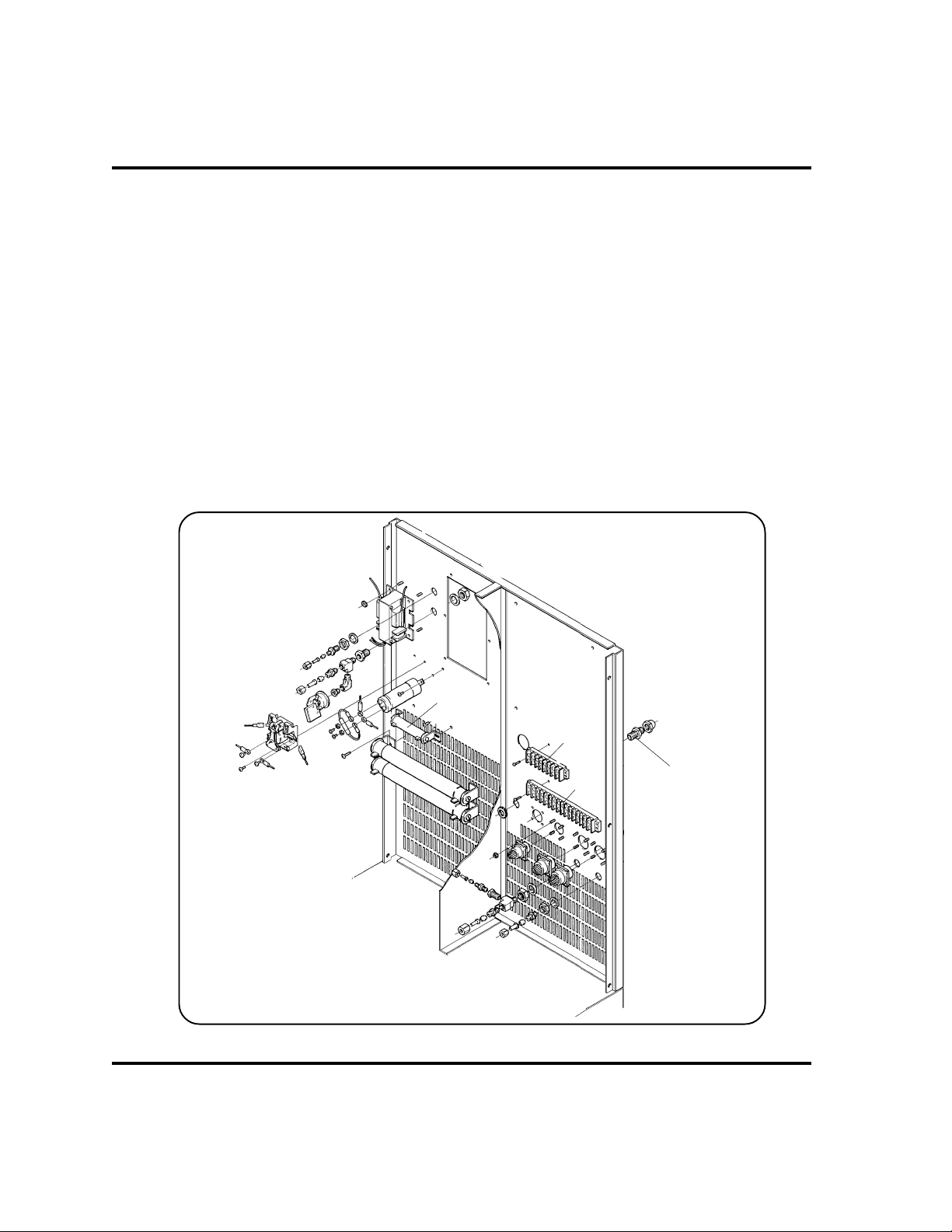
1. Remove top panel and both left and right side panels of the MAX200.
2. Remove voltage divider template from the last page of this manual and punch out the
four mounting holes. Check dimensions as provided on template.
3. Place template approximately as shown in Figure 1b-1.
4. Mark the hole locations with a pencil and remove template.
5. Protect the base of the MAX200 (especially the transformer) with a cloth, and drill the
four holes using a #29 drill bit.
6. Unscrew the 4 screws from the voltage divider.
7. Mount the voltage divider as shown in Figure 1b-2 with the white wire facing down.
Screw the voltage divider in place from the center wall right rear side (see Figure 1b-1).
8. Carefully remove protective cloth and blow out any metal shavings inside of MAX200
power supply with shop or compressed air.
Page 1b-2
THC-2 Torch Height Control
Page 19

Top of MAX200
power supply
Figure 1b-1 Voltage Divider Template Location - MAX200 Center Wall Right Rear
INSTALLATION - MAX200
Lifting eye
Voltage divider template and
screw hole locations
Cable assembly
Feed-thru
Lifting eye
Top of MAX200
Voltage divider
mounting
location
Feed-thru
White wire
Figure 1b-2 Voltage Divider Mounting Location - MAX200 Center Wall Left Rear
power supply
THC-2 Torch Height Control
Page 1b-3
Page 20
INSTALLATION - MAX200
INSTALL INTERCONNECT CABLE TO MAX200
1. Connect the interface cable to RECP2 on the THC-2 module.
2. Loosen the adjustable strain relief on the rear of the MAX200 power supply - Fig. 1b-3.
3. Thread the other end of the interface cable through this strain relief and make
connections to TB4, TB3 (Fig. 1b-3) and voltage divider as shown in the Figure 1b-4
wiring diagram. Note: Push wires labeled 42 and 70 through the center wall feed-thru to
get to voltage divider.
4. Connect the white wire from the voltage divider to location #45 on R4 which is located on
the left rear wall of the MAX200 power supply - Fig. 1b-4.
This completes installation of the THC-2 to the MAX200. See Section 2 for operation
instructions.
Page 1b-4
R4
TB4
Strain Relief
TB3
Figure 1b-3 Inside Rear of MAX200 Power Supply
THC-2 Torch Height Control
Page 21
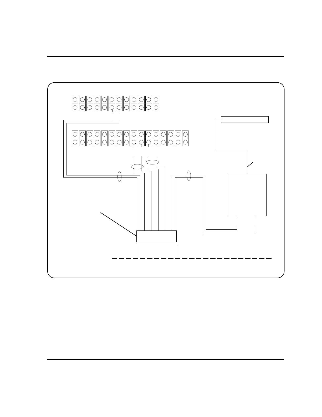
88 89
INSTALLATION - MAX200
TB4
Interconnect Cable
1 2
45
R4
82 83 84 85
TB3
33 34 35 36
White Wire
Voltage
Divider
GND SIGNAL
42 70
RECP2
THC-2
Figure 1b-4 Wiring Diagram - THC-2 to MAX200
THC-2 Torch Height Control
Page 1b-5
Page 22

Section 1c INSTALLATION - PAC-500
In this section:
Mount the Voltage Divider to PAC-500.............................................. 1c-2
Install Interconnect Cable to PAC-500 .............................................. 1c-3
THC-2 Torch Height Control
Page 1c-1
Page 23

INSTALLATION - PAC-500
MOUNT THE VOLTAGE DIVIDER TO PAC-500
Be sure to complete all steps in Section 1: Installation - To Cutting Machine & Torch Lifter in addition to the following procedure for hooking the THC-2 to the PAC-500.
WARNING!
The line disconnect switch for the PAC-500 must be in the OFF position
before proceeding with the installation of the voltage divider and interconnect
cable.
1. Open the left door of the PAC-500 plasma control console (plumbing compartment) and
place the voltage divider on the floor of the console - Fig. 1c-1.
2. Attach the white wire from the voltage divider to terminal 34 located on the cathode block
- Fig. 1c-1.
Page 1c-2
34
Approximate location
of Voltage Divider
Figure 1c-1 PAC-500 Plasma Control Console Plumbing Compartment
THC-2 Torch Height Control
Page 24

INSTALLATION - PAC-500
INSTALL THE INTERCONNECT CABLE TO PAC-500
1. The cable from the THC-2 to the PAC-500 console must be fabricated. Hypertherm
recommends using 3-pair 22-gauge shielded cable. The cable will run between the
plasma control console and the THC-2 module. Be certain to supply a cable that will
reach between these two components.
2. Strip the outer shielding away on both ends of the cable and tag individual wire ends 1
through 6. Tag both ends so that wire "1" on one end is the same wire that is marked "1"
on the other end, etc.
3. Crimp #6 terminals on all wires on one end of the cable. On the other end of the cable,
crimp #6 terminals on wires 4 and 6 and strip and tin the remaining wires.
4. Feed the cable end with all terminals attached through one of the strain reliefs of the
plasma control console - Fig. 1c-2.
Strain Reliefs
GAS OUT
WATER OUT
PAC-500
Figure 1c-2 PAC-500/500L Plasma Control Consoles
Strain Reliefs
Strain Reliefs
PAC-500L
THC-2 Torch Height Control
Page 1c-3
Page 25
INSTALLATION - PAC-500
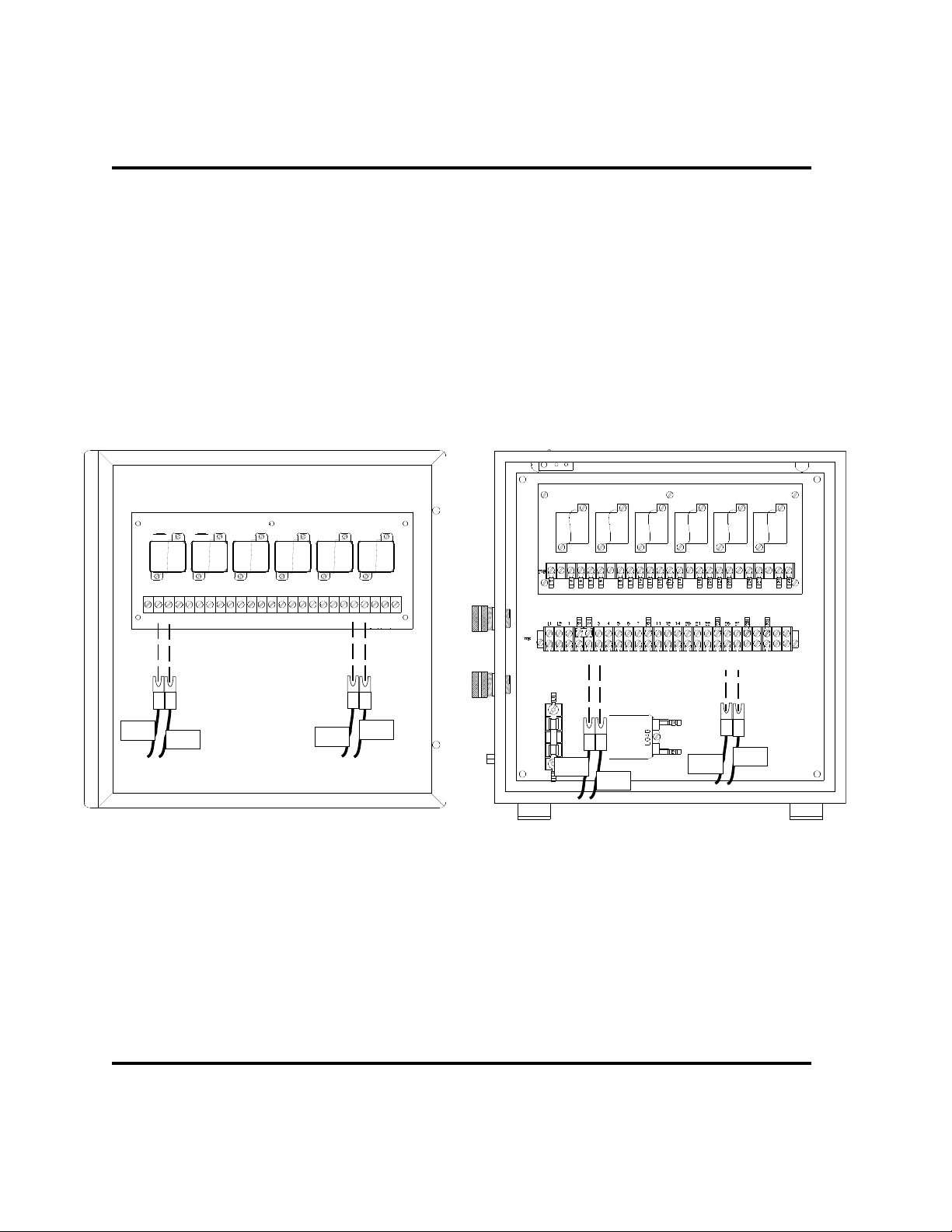
5. Make the following connections to 1TB located on the console door of the PAC-500, or
on the inside of the PAC-500L - Fig. 1c-3:
Cable wire labeled 1 to 1TB terminal labeled 3
Cable wire labeled 2 to 1TB terminal labeled 2
Cable wire labeled 3 to 1TB terminal labeled 26
Cable wire labeled 4 to 1TB terminal labeled 27
1TB
2
2 2 3
26 27
4
1
3
1TB
2
2 2 3
2 2 3
1
PAC-500
Figure 1c-3 PAC-500/500L Plasma Control Consoles - 1TB Location
PAC-500L
26 27
26 27
4
3
Page 1c-4
THC-2 Torch Height Control
Page 26

INSTALLATION - PAC-500
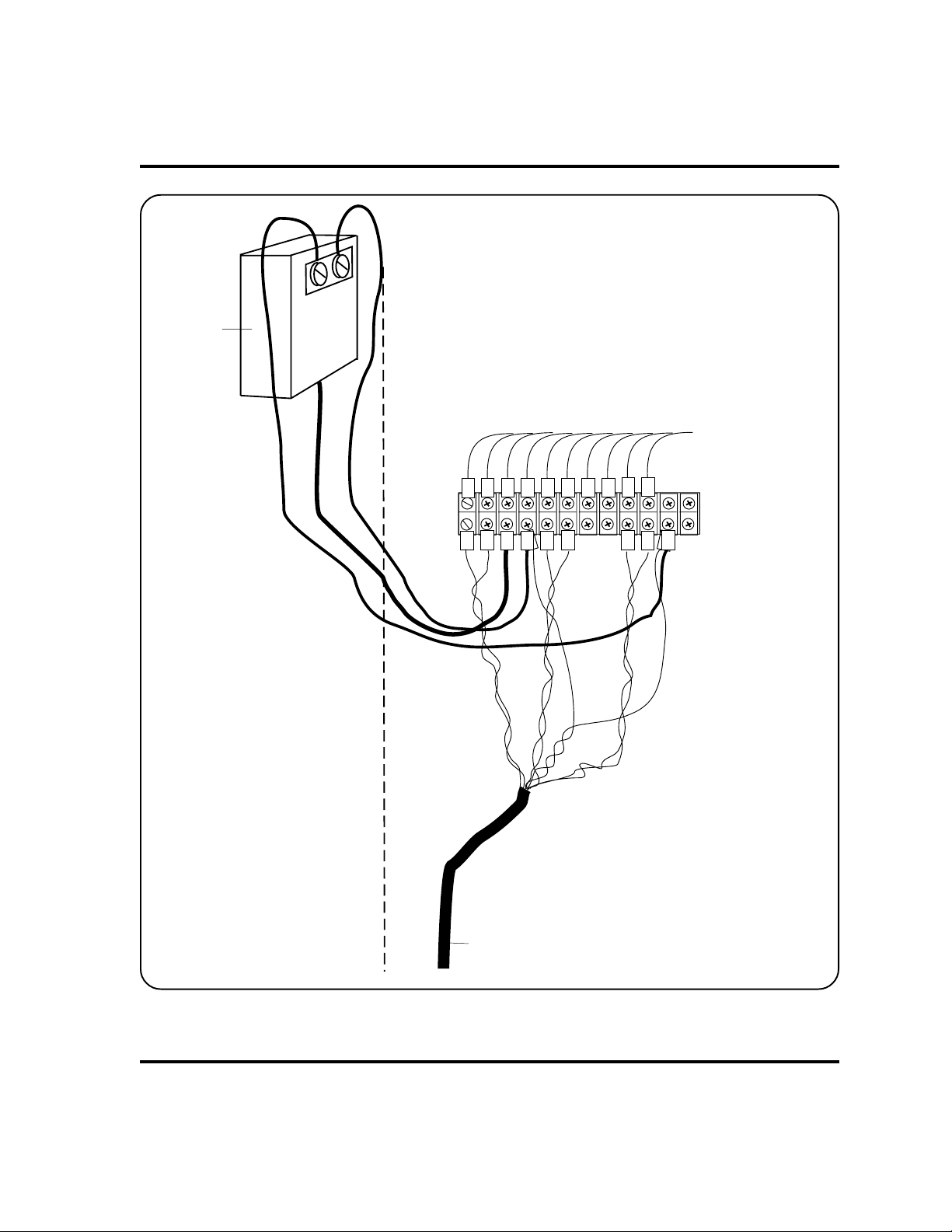
6. Run cable wires 5 and 6 through the feed hole in center wall of plasma control console
(Fig. 1c-4) and attach wire 5 to voltage divider terminal labeled
voltage divider terminal labeled GROUND.
Feed wires 5 and 6 through
to other side
SIGNAL and cable 6 to
Figure 1c-4 HF Compartment - PAC-500 Console
THC-2 Torch Height Control
Note: Internal components shown in HF
Compartment may vary from your unit
Page 1c-5
Page 27

INSTALLATION - PAC-500
7. Pass the remaining end of the interconnect cable through the strain relief on the rear of
the THC-2 module.
8. Facing the rear of the THC-2 module with the cover removed, look down inside the
module and observe where one of the wires from the THC-2 receptacle RECP2
connects to the rear-panel fuse (1FU) - Fig. 1c-5. Cut this wire and solder interconnect
cable wire labeled "1" to the end of the wire that goes to the fuse.
Figure 1c-5 Top Rear View of THC-2
Cut and solder wire "1" here
1FU
RECP2
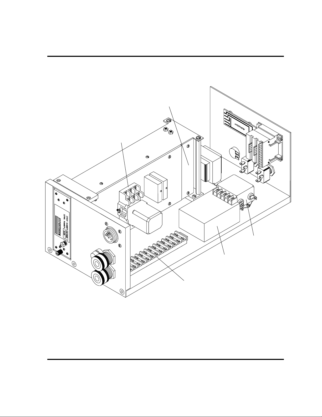
9. Find the line filter (1F) on the inside of the THC-2 module - Fig. 1c-6. Solder interconnect
10. Find the timer relay device (1TD) in the THC-2 - Fig. 1c-6. Attach interconnect cable wire
11. Find the power supply (1PS) in the THC-2 - Fig. 1c-6. Attach interconnect cable wire
12. Find the 390Ω 1/8 W resistor (R1) that THC-2 wire labeled 118 connects to - Fig. 1c-6.
13. Find the big terminal strip (1TB) in the THC-2 module - Fig. 1c-6. Attach interconnect
This completes installation of the THC-2 to the PAC-500. See Section 2 for operation
instructions.
Page 1c-6
cable wire labeled "2" to terminal that has THC-2 wire labeled 102 connected to it.
labeled "3" to timer relay terminal that has THC-2 wire labeled 108 connected to it.
labeled "4" to power supply terminal that has THC-2 wire labeled 107 connected to it.
Solder interconnect cable wire labeled "5" to the wire end of that resistor.
cable wire labeled "6" to terminal 119 (ground).
THC-2 Torch Height Control
Page 28
INSTALLATION - PAC-500
1TD
Attach wire labeled #3
to terminal labeled #108
R1 - 390
location)
Solder wire labeled #5 to
the wire end of this
resistor
Ω (approximate
Figure 1c-6 Inside View of THC-2
THC-2 Torch Height Control
1F
Solder wire labeled #2
to terminal labeled #102
1PS
Attach wire labeled #4
to terminal labeled #107
1TB
Attach wire labeled #6
to terminal labeled #119
(ground).
Page 1c-7
5
Page 29

Section 2 OPERATION
In this section:
Description of Controls and Indicators ................................................2-2
Operating Instructions .........................................................................2-3
Notes on Operation ........................................................................2-3
THC-2 Torch Height Control
Page 2-1
Page 30

OPERATION
DESCRIPTION OF CONTROLS AND INDICATORS
• VOLTAGE thumbwheel
Sets the plasma arc voltage for the AVC (Automatic Voltage Control).
• POWER ON/OFF switch
Turns power to the THC-2 on or off.
• AVC START/STOP switch
Activates or deactivates the Automatic Voltage Control.
• MACHINE DELAY knob
Sets the delay time for the motion of the cutting machine after arc transfer.
• UP/DOWN LEDs
Indicates when the THC-2 gives the cutting machine a signal to move up or down.
• POWER ON LED
Indicates that the POWER switch to the THC-2 is on.
• AVC ON LED
Indicates that the AVC START switch is on.
Page 2-2
Figure 2-1 THC-2 Front Panel
THC-2 Torch Height Control
Page 31

OPERATING INSTRUCTIONS
1. Turn POWER to the THC-2 ON.
2. Turn the AVC switch to START.
3. Find the Arc Voltage setting for the type of metal and thickness of metal you are
cutting in the
manual. Adjust the VOLTAGE thumbwheel to the recommended arc voltage setting.
4. Find the Pierce Time or Approx. Motion Delay Time for the type of metal and
thickness of metal you are cutting in the
section of your instruction manual. Adjust the MACHINE DELAY knob to the
recommended setting for Pierce Time or Approx. Motion Delay Time. (The range of
machine delay is from .1 sec to 2 sec.)
5. Find the Torch-to-Work Distance for the type and thickness of metal you are cutting
in the
Operating Data
Adjust the torch height to the proper torch-to-work distance before starting cut.
The THC-2 is now ready for operation and will be activated after the plasma START
command is given.
Operating Data
or
Cut / Gouging Chart
or
Cut / Gouging Chart
Operating Data
OPERATION
section of your instruction
or
Cut / Gouging Chart
section of your instruction manual.
Notes on Operation
• Placing the AVC switch to STOP during the cut will halt AVC control.
• In order to increase the torch height, adjust the voltage on the thumbwheel to a
higher value. In order to decrease the torch height, adjust the voltage on the
thumbwheel to a lower value.
– Each 5 volt change on the thumbwheel is approximately equal to a .050 inch
change in torch-to-work distance.
THC-2 Torch Height Control
Page 2-3
Page 32

Section 3 PARTS LIST
In this section:
THC-2 Torch Height Control Systems .................................................3-2
Torch Height Control System for MAX100, MAX100D, MAX200 ....3-2
Torch Height Control System for PAC-500 .....................................3-2
THC-2 Interconnect Cable - #023264 .................................................3-3
THC-2 Control Module - #053005 .......................................................3-5
THC-2 Torch Height Control
Page 3-1
Page 33

PARTS LIST
THC-2 TORCH HEIGHT CONTROL SYSTEMS
Torch Height Control System for MAX100, MAX100D, MAX200
Part
Number Description Qty.
052002 THC-2 Torch Height Control MAX100/200
023264* Cable:MAX100/THC2 5' 1
041007** Volt Divider THC1/THC-2 1
053005*** Control Module, THC-2 1
800200 IM20:THC-2 Torch Height Control 1
Torch Height Control System for PAC-500
Part
Number Description Qty.
052001 THC-2 Torch Height Control PAC-500
041007** Volt Divider THC1/THC-2 1
053005*** Control Module, THC-2 1
800200 IM20:THC-2 Torch Height Control 1
* See page 3-3 for detail
** See page 3-8 for picture
*** See pages 3-4 through 3-7 for detailed parts breakdown.
Page 3-2
THC-2 Torch Height Control
Page 34
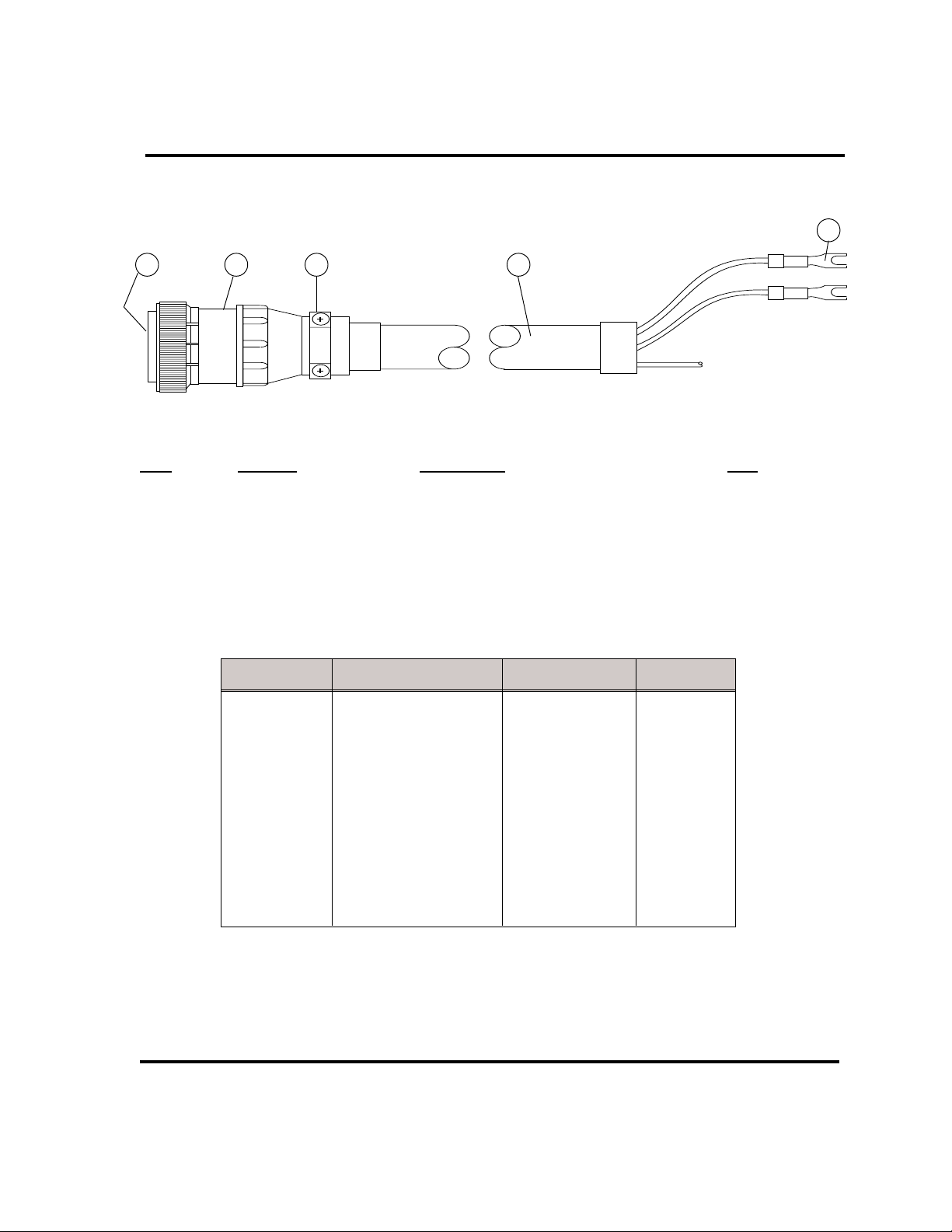
THC-2 INTERCONNECT CABLE - #023264
PARTS LIST
5
21 3 4
Part
Item Number Description Qty.
023264 Cable: MAX100 THC-2 5'
1 008186 Skt:24-20 AWG Type III 9
2 008191 Plug Shell:CPC 17-16 Std Sex 1
3 008192 Caclp:CPC Size 17 1
4 047027 Cable, 22-6 TW Pr, OA Shielded 5 ft
5 074027 Term, 22-16 #6 Lck Fork Insul 8
Terminal# Wire Function Color Code Socket#
1 120VAC neutral Black 2
2 120VAC hot White 1
1
2
etc.
33 Plasma Start White 3
34 Plasma Start Brown 4
35 Machine Motion Orange 14
36 Machine Motion White 12
42 Arc Voltage + White 8
70 Arc Voltage - Red 7
Figure 3-1 THC-2 Control Cable - MAX100/100D/200
THC-2 Torch Height Control
Page 3-3
Page 35
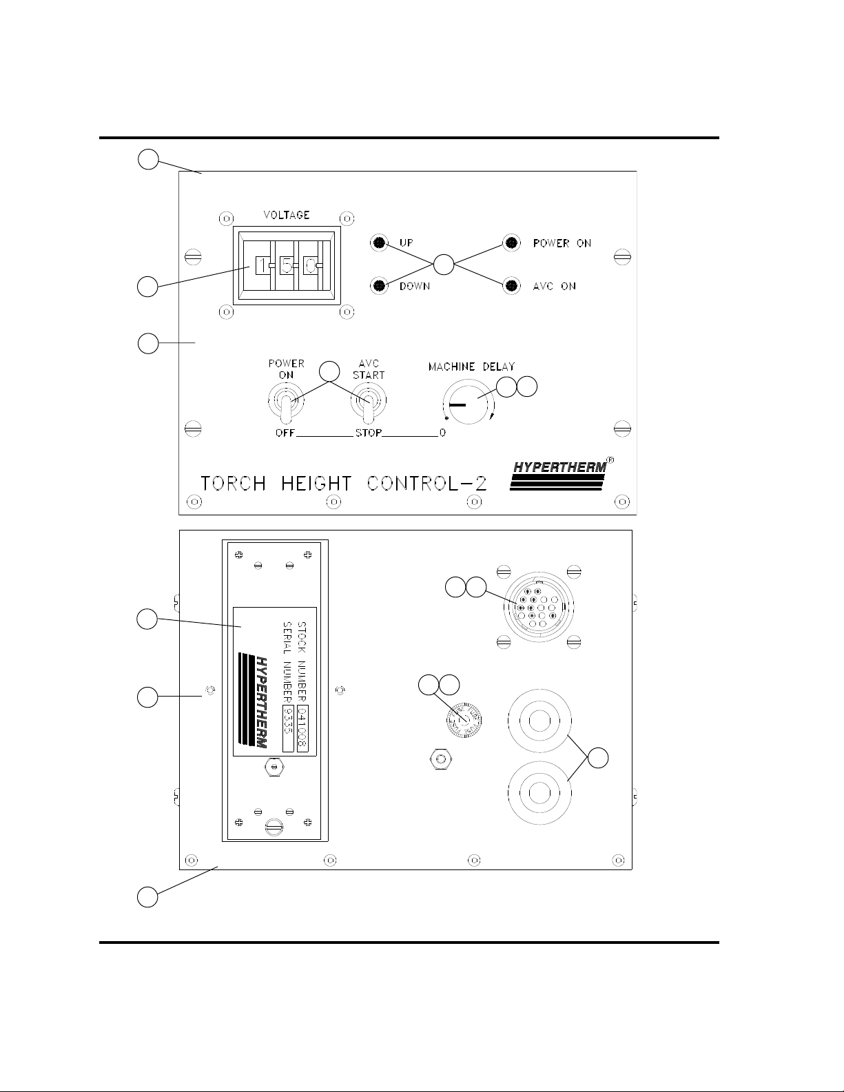
PARTS LIST
3
9
1
12
8
13
14
15
2
4
Page 3-4
1110
5 6
7
Figure 3-2 THC-2 Front and Rear Panels
THC-2 Torch Height Control
Page 36

THC-2 CONTROL MODULE - #053005
Part
Item Number Description Designator Qty.
001037 Cov:THC-2 Rear Acs 1
029019 Card Cage SA:THC2 PC 1
1 001034 Pnl:THC-2 Fr 1
2 001035 Pnl:THC-2 Rear 1
3 001057 Pnl:THC-2 Top 1
4 001058 Pnl:THC-2 Bot 1
5 008068 Fuseholder:Pnl Mt 1P 1/4 X 1-1/4 1
6 008069 Fuse:3/8A 250V 1/4 X 1-1/4 Slo 1FU 1
029024 Harn:THC-2 053005 1
7 008070 Strainrlf:1/2NPT X .312-.375 2
8 005044 Tgl Sw:SPDT Maint ON 1,2 TGS 2
9 005052 Thmbwhl Sw:Rear Mtg S1 1
10 008193 Rcpt Shell:CPC 17-16 RECP2 1
11 008176 Pin: 24-20 AWG Type III 8
12 009306 Plt Lt:Red LED T-1 3 1,2,3,4 LT 4
13 008164 Knob: .735 Dia. 1/4 Sft Blck 1
14 009442 Pot:50K-Ohm 10% 1W 1T Cerm 1 POT 1
15 041008 PC BD Assy Digital/Analog THC2 2PC 1
PARTS LIST
THC-2 Torch Height Control
Page 3-5
Page 37

PARTS LIST
10
5
6
2
13
4
3
Page 3-6
5
11
12
14
8
7
9
1
Figure 3-3 THC-2 Interior
THC-2 Torch Height Control
Page 38

THC-2 CONTROL MODULE - #053005 (cont.)
Part
Item Number Description Designator Qty.
1 009040 Filter:3A 3WT AC Elek 1F 1
2 014003 Xfmr:15VA 115V In/Out ISln 1T 1
029019 Card Cage SA:THC2 PCB 1
** 041737 Relay PCB Assembly 1
3 003040 Rly:120VAC TD IceCube 1TD 1
4 003097 Rly:250VAC Sol State I/O Conv SSR1,2 2
5* 009034 Diode:12V 210ma 10W 10% Zener Z1 1
6* 009484 Res:390-Ohm 1/4W 5% CBN CMPSN R1 1
029024 Harn:THC2 053005 1
7 008073 Terminal Board: 16-Term 1TB 1
8 008070 Strainrlf:1/2NPT X .312-.375 2
9 005044 Tgl Sw:SPDT Maint ON 1,2 TGS 2
10 005052 Thmbwhl Sw:Rear Mtg S1 1
11 008193 Rcpt Shell:CPC 17-16 RECP2 1
12 008176 Pin: 24-20 AWG Type III 8
13 009442 Pot:50K-Ohm 10% 1W 1T Cerm 1 POT 1
14 041011 Power Source, THC-1/THC-2 1PS 1
PARTS LIST
* Approximate location pointed to.
** This PCB assembly and it's associated parts can not be used in units produced before 5/2001.
THC-2 Torch Height Control
Page 3-7
6
Page 39
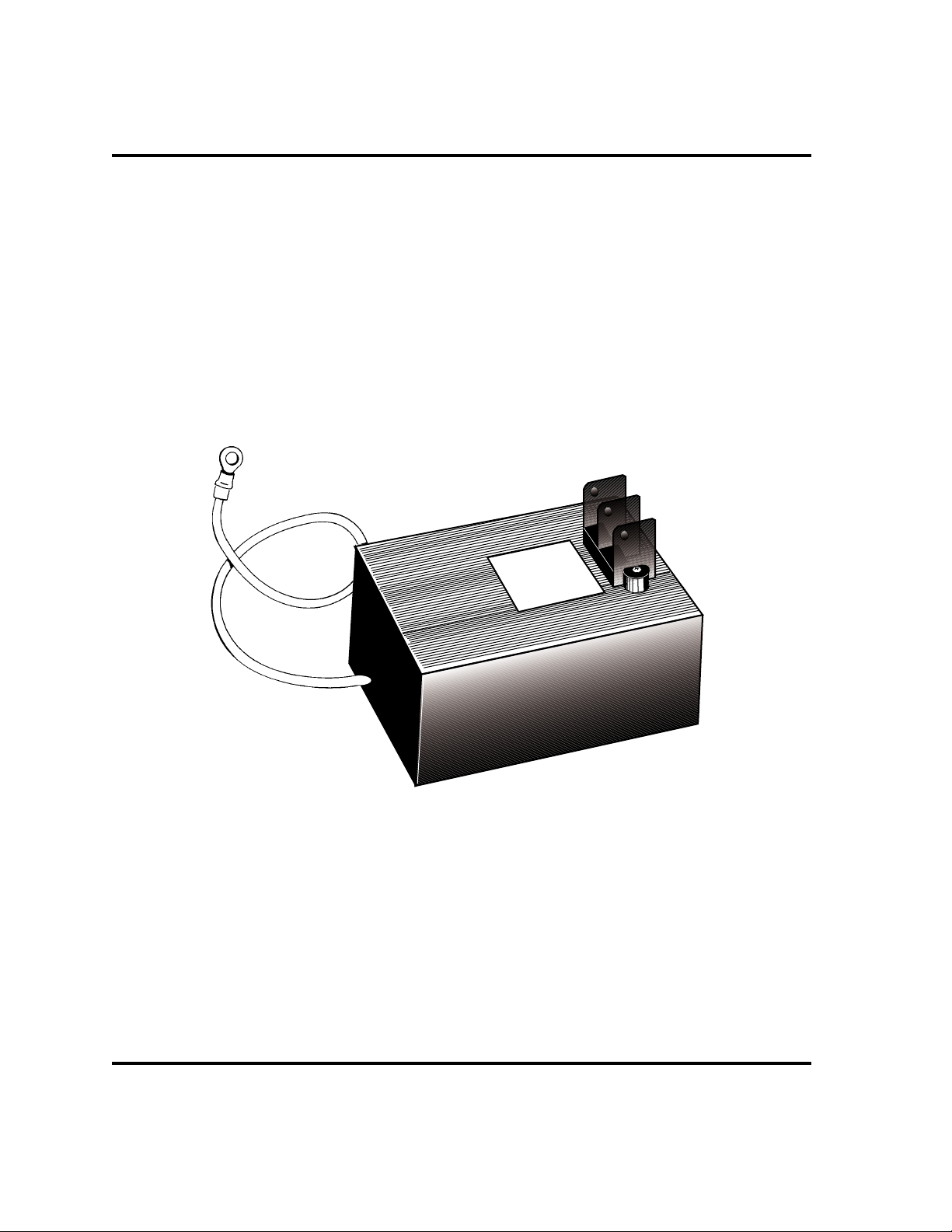
PARTS LIST
SIGNAL
GROUND
Page 3-8
Figure 3-4 Voltage Divider -041007
THC-2 Torch Height Control
Page 40
Page 41

3-7/16" (87mm)
center to center
2-5/16" (59mm)
center to center
Voltage Divider Mounting Template for MAX200
 Loading...