

Page 1
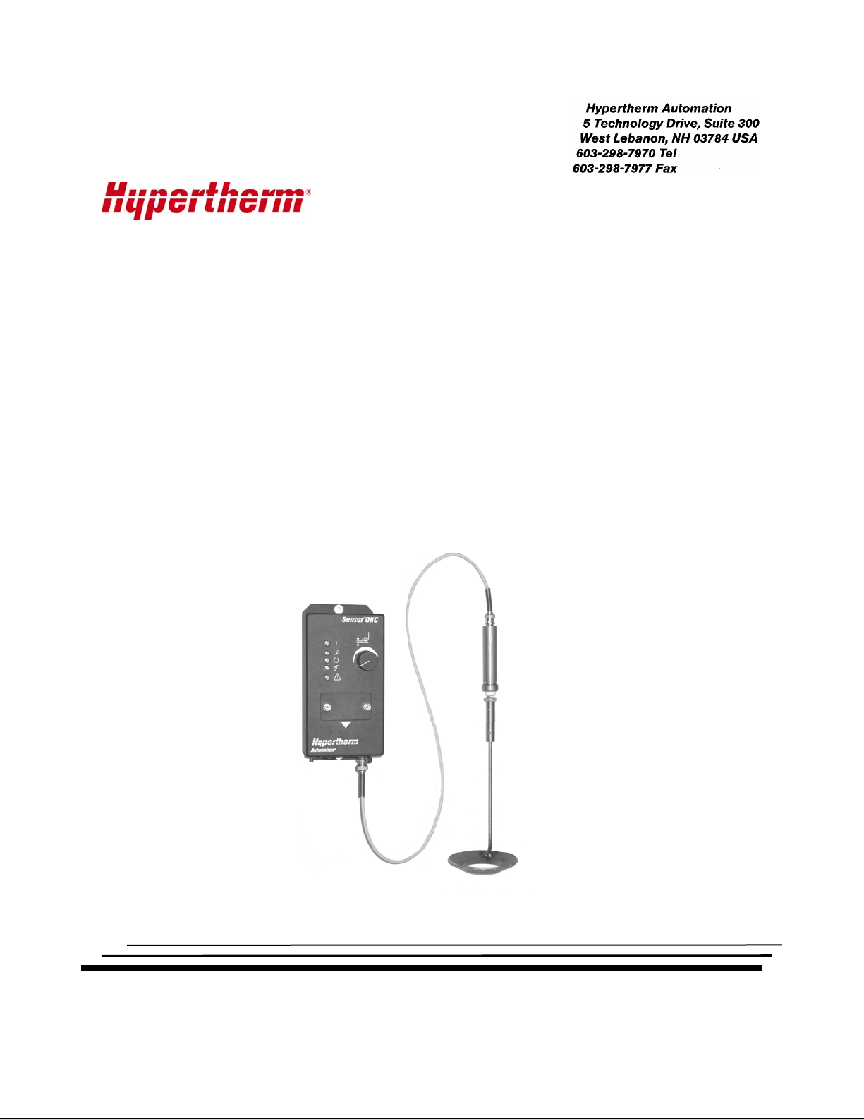
HYPERTHERM SENSOR™ OHC
A
UTOMATED OXY HEIGHT CONTROL
PERATION & SET UP GUIDE
O
Making people and machines more productive through process Automation
Page 2

D
ISCLAIMER The information in this document is subject to change without notice and should not
be construed as a commitment by Hypertherm Automation
Automation
®
assumes no responsibility for any errors that may appear.
T
RADEMARKS Hypertherm Automation is a wholly owned subsidiary of Hypertherm
®
. Hypertherm
®
, Inc.
Sensor™ is a trademark of Hypertherm Automation.
AR-300/100W Levilator Clearance Control is a trademark of CMC Burny.
C
OPYRIGHT ©2004 by Hypertherm Automation. All rights Reserved
Printed in USA
Page 3

Table of Contents
SAFETY ................................................................................................................................................ 1
Read This Manual ............................................................................................................................. 1
Dangerous Machinery ....................................................................................................................... 1
High Voltages.....................................................................................................................................1
SECTION 1: OVERVIEW .................................................................................................................. 3
Introduction ....................................................................................................................................... 3
Description and Features.................................................................................................................. 4
Hardware Specifications................................................................................................................5
Control Unit Front ............................................................................................................................6
Control Unit Bottom.......................................................................................................................... 7
Sensor and Mounting Isolator .......................................................................................................... 8
SECTION 2: OPERATION ................................................................................................................ 9
Operation Modes................................................................................................................................ 9
Automatic Operation .....................................................................................................................9
Manual Operation.......................................................................................................................... 9
Errors.............................................................................................................................................. 9
Error Conditions..............................................................................................................................10
SECTION 3: INSTALLATION AND SET UP ..............................................................................11
Installation....................................................................................................................................... 11
Sensor Mounting .......................................................................................................................... 11
Sensor Position to Torch..............................................................................................................11
Connectors....................................................................................................................................12
Power Connections....................................................................................................................... 12
Limit Switch.................................................................................................................................13
Digital I/O..................................................................................................................................... 13
Optional External Height Set Pot............................................................................................... 13
Optional External Second Height Set Pot.................................................................................. 13
Standard Wiring Installation...................................................................................................... 15
IO Interfacing ..................................................................................................................................16
IO Interfacing Examples ............................................................................................................. 16
DIP Switch Setup ............................................................................................................................17
Calibration Procedure .....................................................................................................................18
Component List ...............................................................................................................................19
Optional Sensor Cables ...............................................................................................................19
Page 4

Page 5

Safety 1
Safety
Read This Manual
Read and understand this instructional manual, the cutting machine manuals, and your
employer’s safety practices. Note: This product is not designed to be field serviceable. Please
return to an authorized repair center for any required service.
Dangerous Machinery
Operation and maintenance of automated equipment involves potential hazards. Personnel
should take precautions to avoid injury.
Injury and entanglement may occur if hands and limbs come in contact with moving machinery.
KEEP HANDS CLEAR of dangerous moving machinery. All control, including manual, can be
affected using the remote interface.
Loose fitting clothing or ties may become entangled in the machinery. These items should not be
worn while operating or servicing the machine.
High Voltages
Electric shock can kill. Be sure this equipment is safely installed in accordance with the enclosed
procedures and specifications.
Avoid contact with electrical wires and cabling while power is on.
This equipment should only be opened by trained service personnel.
Please refer to the appropriate appendix in the Installation Guide provided with your control for
details on safety certification for that product.
Page 6

2 Sensor OHC Operation and Set Up Guide
Page 7

Section 1: Overview 3
Section 1: Overview
Introduction
One of the most important parameters in Oxy Torch cutting is consistent torch tip to plate standoff
distance. The Hypertherm Sensor OHC uses a capacitive sensor to measure the torch to plate
distance. The unit will drive a DC motor on the torch lifter to automatically maintain a user
selected torch to plate distance. This automatic closed loop control of the torch height will
dramatically improve the cutting speed, quality and consistency.
The Sensor OHC includes the control unit, the capacitive sensor, sensor mounting isolator,
sensor spring style breakaway, and standard 1 meter coax cable. A connector kit is available for
the standard mating connectors. For demonstration purposes, a connector conversion kit is
available that will make the unit plug compatible with the Burny AR 300/100 “Levitator Clearance
Controller”.
It is the installer’s responsibility to provide a compatible lifter mechanism. A compatible lifter will
utilize a 24Vdc motor between 2 Amps, 50 Watts and 6 Amps 150 Watts. The full speed
operation must be geared to produce a linear full speed of between 20 in/ min (500 mm/min) and
140 in/min (3500 mm/min). The tradeoff being between a low speed extremely high accuracy lifter
and a high speed lower accuracy lifter. The lifter should have adequate rigidity and very little
backlash and moving inertia. The lifter should also have normally closed upper and lower limit
switches mounted at the extremes of travel.
The installer must also provide an appropriate mounting clamp that will attach the 20 mm
diameter sensor mounting isolator to the torch. The mounting clamp should be designed for a
center of torch to center of isolator distance of 2 inches or 50mm so that that the sensor ring will
be properly centered and positioned around the torch tip. Additionally, the mounting clamp
should provide a good electrical ground connection to the overall machine frame and to the metal
plate being sensed. Failure to provide an adequate ground connection to the plate will have a
negative effect on the height measurement and control accuracy.
Main Power Supply: 24Vac +/- 10%, 50, 60 Hz
Compatible Lifter Motors DC shunt, 24Vdc, 2 Amps to 6 Amps
Max Power Output 150 Watts
Page 8

4 Sensor OHC Operation and Set Up Guide
Description and Features
SENSOR™ OHC - Oxy Height Control is an advanced automated height control system for
oxy fuel shape cutting applications. This product utilizes advanced capacitive sensing and
microprocessor technology to automatically detect the plate and adjust torch position to a
desired set point during oxy fuel cutting operations. This reduces operator input, improves
accuracy and increases productivity.
Features
¾ Sensor OHC can be used with any CNC
¾ Easy setup & operation
¾ Both manual & automatic operation modes
¾ Microprocessor control for increased sensitivity and control
¾ High positioning speeds possible with up to 6 amps continuous current and linear
adjustment over full range
¾ Built-in diagnostic and fault detection features
¾ Auto retract on plate contact
¾ Optional second height set point input for preheat or pierce
¾ Indicator lights for operation including:
⇒ Power On
⇒ Upper Limit Switch
⇒ Lower Limit Switch
Options
¾ Five Cable Lengths from 19.7” (500mm) to 59” (1500mm)
¾ Adapter cables allowing direct replacement for existing AR-300/100W Levilator Clearance
Controls
⇒ In Position Indicator
⇒ Attention / Error indicator
System Features*
Compatible Motors DC shunt 24VDC, 2 Amps to 6 Amps ( customer supplied )
Max Power Output 150W
Control Range Linear 0.1” (2.5mm ) to 1.0” (25mm)
Motor Output Full “H” bridge PWM with current sensing
Accuracy .01” (.25mm )**
Operator controls Easy to use control set point knob and easy read indicators
Calibration Easy access calibration pot on front Panel
Measuring Technology Capacitive Ring with Coax Cable
Dimensions 8.50” (216mm ) W x 4.21” (107mm) D x 4.02” (102mm) H
Inputs/ Outputs 3 outputs and 6 inputs optically isolated on “D” connectors
Weight 2.4 lbs
Operating Environment 0 to 50C; 95% relative humidity (non-condensing)
Power 24VAC +/- 10% 50/60 Hz
*Information subject to change without notice.
** Dependent on customer supplied lifter mechanics
Page 9

Section 1: Overview 5
Hardware Specifications
Main Power Supply: 24 Vdc +/- 10%, 50/60 Hz
Compatible Lifter Motors: DC shunt motor 24Vdc, 2 Amps to 6 Amps
Operating Temperature: 0 to +50 deg C
Control Range: Linear 0.1 inch to 1.0 inch (2.5 to 25 mm)
(standard sensor & cable)
Height Measuring Technology: Capacitive Ring with Coax Cable
Accuracy: 0.01 inch (0.25 mm) w/ representative Lifter
(dependent on lifter mechanics)
HF Coax Cable: 500 mm to 1500 mm (1000 mm standard)
Standard Sensor: Stainless Steel Ring 100 mm outer & 50 mm inner
diameters. Can be calibrated for others
Dimensions:
Control Type: Digital Micro Processor based
Motor Output: Full “H” Bridge PWM with current sensing
Control Interface: Optically Isolated I/O on “D” connectors
Outputs: Digital In-Position Output
Digital Error Output
Digital Plate Contact Output
Inputs: Digital Manual/Auto Select
Digital Manual Up
Digital Manual Down
Digital Upper Limit Switch
Digital Lower Limit Switch
Digital Second Height Select
Remote Height Set-point Pot
Second Height Set-point Pot
Front Panel Indicators green Power
yellow Upper Limit Switch
green In Position
yellow Lower Limit Switch
red Attention/Error Code
8.50” (216mm) W x 4.21” (107mm) D x 4.02” (102mm) H
Page 10

6 Sensor OHC Operation and Set Up Guide
g
Control Unit Front
Power Indicator
Upper Limit Indicator
In Position Indicator
Lower Limit Indicator
Error Code Indicator
ht Set Point Adjust
Hei
Set Up & Calibration
Access Panel
Page 11

Section 1: Overview 7
Control Unit Bottom
Capacitive Sensor
Ground
Limit Switches
Power & Motor
Control Interface
6 Amp Fuse
Page 12

8 Sensor OHC Operation and Set Up Guide
Sensor and Mounting Isolator
Mounting Isolator
Spring Breakaway
Capacitive Sensor Ring
Page 13

Section 2: Operation 9
Section 2: Operation
Operation Modes
The two basic modes of operation are “Automatic” and “Manual”.
Note: The control unit must be calibrated prior to use. See calibration instructions in this guide.
Automatic Operation
“Automatic” mode is active whenever the “Manual” input on pin-3 of the 15 pin I/O connector is
open. During “Automatic” operation, the height of the torch is constantly maintained at the set
height. When the unit is operating, the green “In-Position” front panel light and corresponding I/O
output will indicate that the unit is maintaining the set height. At any time during “Automatic”
operation the set height can be changed and the unit will quickly respond and position to the new
desired height. The ‘Up/Down” switch can be used at any time to temporarily override automatic
operation and force the lifter to move in the desired direction. As soon as the Up/Down switch is
released, the unit will return to automatic operation. Activation of either limit switch will prohibit
further motion in that direction.
Manual Operation
“Manual” mode is activated by connecting the input on pin-3 of the 15 pin I/O connector to the
signal Ground on pin-2. In manual mode, the unit is controlled by using the Up/Down switch only.
The control will not respond to the “Set Height” and will stay fixed in the position that it was last
driven to using the Up/Down switch. The Up/Down switch has two speeds depending on how long
it is held active. During the first second, the control will move at low speed to allow the operator to
finely position the torch. The low speed can be maintained by pulsing the Up/Down switch. If the
Up/Down switch is maintained for more than one second, then the control will shift to full speed to
drive the lifter in the desired direction. Activation of either limit switch will prohibit further motion in
that direction.
Errors
During “Automatic” operation mode, if the sensor should come too close to the plate (less than
1/10 inch or 2.5 mm), the unit will automatically force a retract in an attempt to avoid a crash. This
error condition and others listed in the following figure will be indicated by a code number that
flashes on the red “Error” front panel light. Any error will also cause the “Error” output on the I/O
connector to become active until the error is corrected.
Page 14

10 Sensor OHC Operation and Set Up Guide
Error Conditions
Red Error LED
Error Indications
The red ERROR LED indicates abnormal conditions by flashing an error code. The error code
meanings are listed below.
1 Flash - Sensor Shorted Error
Indicates that the sensor is in contact with the plate. In Auto Height mode, this will cause a rapid
retract until the sensor no longer is in contact with the plate. This may also indicate that recalibration is required
2 Flashes - Sensor Open Error
Indicates that the sensor is not plugged in or the sensor cable has opened. In Auto Height
mode, this error will disable all motion. This may also indicate that re-calibration is required
3 Flashes - Input Voltage Low
Indicates that the 24Vac power source has dropped more than 25% below nominal. Check the
power source and all connections.
4 Flashes - Input Voltage High
Indicates that the 24Vac power source is more than 20% high and may cause damage to the
unit.
5 Flashes - Motor Drive Over Temp Warning
Suspend operation and allow unit to cool down.
6 Flashes - Invalid data in the selected cable length data table.
Set DIP switches 1 thru 3 to a valid cable length setting.
Page 15

Section 3: Installation and Set Up 11
Section 3: Installation and Set Up
Installation
Sensor Mounting
The sensor connection is thru the coax cable to the sensor mounting isolator. It is the
responsibility of the installer to provide a mounting clamp that will correctly position the sensor
ring with respect to the torch tip. The mounting clamp should be designed for a center of torch to
center of isolator distance of 2 inches or 50mm so that that the sensor ring will be properly
centered and positioned around the torch tip. Additionally, the mounting clamp should provide a
good ground electrical connection between the sensor mounting isolator and the machine frame.
Sensor Position to Torch
Page 16

12 Sensor OHC Operation and Set Up Guide
Connectors
Wire the unit as shown with reference to the following figures. A standard mating connector kit is
available which provides the mating 9 pin & 15 pin “D” type connectors and the 7 pin circular
power connector (CONN-0141). Also available for drop-in demonstration purposes is a connector
conversion kit that will adapt the unit to AR300/100 style connectors (CABL-0163). It is
recommended that you use the AR300/100 conversion kit for demonstration purposes only. Use
of the plastic housings on the AR300/100 style connectors does not allow for proper cable
shielding. Improper cable shielding can result in severe electrical interference problems.
Control Interface
Limit Switches
Power & Motor
Power Connections
All power connections are made to the 7 pin circular connector. When connecting to the motor,
ensure that the motor polarity is such that if pin 2 is positive with respect to pin 5 the slide will
move in the UP direction. The 24 Vac power source is connected between pins 3 and 6. Pin 4 is
connected internally to the grounding stud on the enclosure and the ground stud should be
connected to the machine chassis.
24VAC Input / Motor Pinout
7 Pin Amp Connector
Pin Description
3 24VAC
6 24VAC Return
4 Ground
2 Motor
5 Motor
Page 17

Section 3: Installation and Set Up 13
Limit Switch
The lifter upper and lower limit switches are connected to the 9 pin “D” connector. These switches
are normally closed switches that open when the limit is reached. The upper limit switch connects
between pins 5 & 6 and the lower limit switch connects between pins 2 & 3. This connector also
provides limited +12 Vdc on pins 1 & 4 that can be used to power either optical or hall-effect limit
switches.
Limit Switch Pinout
9 Pin D-Sub
Pin Description
2 Lower Limit ( contact closure )
3 Lower Limit ( contact closure )
5 Upper Limit ( contact closure )
6 Upper Limit ( contact closure )
Digital I/O
The digital I/O interface on the 15 pin “D” connector should include a switch to select between
manual and automatic operation. This switch connects from the input on pin 3 to the signal return
on pin 2. When this switch is closed, the unit will operate in manual mode. The digital I/O
interface also needs a three position center off momentary Up/Down switch to operate in manual
mode or manual override in automatic mode. When the input on pin 4 is connected to the signal
return, the slide will be driven up; and when the input on pin 5 is connected to signal return, the
slide will be drive down. The “Second height Select” input on pin 6 is used to select a second
height set-point from an optional external pot. The optional status output signals “In-Position”,
“Error” and “plate Contact” are available on pins 7 , 8 7 9 respectively. The outputs are transistors
connected to signal return and are capable of switching up to 30V at 100 mA each. A source of
+12V dc is available on pin 1, for use in interfacing to the output signals. Care should be taken
that the total +12 Vdc current drawn from pin 1 plus the current drawn from pins 1 & 4 of the 9 pin
“D” connector, does not exceed 50 mA.
Optional External Height Set Pot
An optional 10K pot can be connected between pins 10 & 11 to allow external setting of the
automatic height set-point. This pot will work in conjunction with the unit’s front panel height
setting pot and both will affect the height set-point. The control unit front panel set pot and the
external set pot are electrically in parallel. This will cause some non-linearity in the height set
point. Usually the front panel control is used as the coarse adjustment and the external pot will
provide a fine tuning of the set point.
Optional External Second Height Set Pot
An optional 10K pot can be connected between pins 12, 13, & 14. This pot will provide an active
height set-point whenever the digital “Second Height Select” input is switched active by
connecting the input on pin 6 to the signal return on pin 2. Unlike the external pot for normal
height set point, this pot will completely override the control front panel height set point. This
external point will provide a linear adjustment of height vs. set point
Page 18

14 Sensor OHC Operation and Set Up Guide
This second external height set point could be useful to provide an independent pierce or preheat
height. By using the digital input “Second Height Select”, it is possible to rapidly switch between
normal height and second height while in motion. Another use for the second set height would be
to effectively disable the control unit front panel height set point pot. This would allow for central
control of cutting height and eliminate the possibility of accidental errors due to the unintentional
changing of the control front panel height set point pot.
I/O and Control Pot Pin out
15 Pin D-Sub
Pin Description
1 I/O Power 12VDC at 50Ma Max
2 I/O Ground
3 Manual Select Input
4 Up Input
5 Down Input
6 Second Height Select Input
7 In Position Output
8 Error Output
9 Plate Contact Output
10 Remote Height Adjust Pot
11 Remote Height Adjust Return
12 Second Height Pot High
13 Second Height Pot Wiper
14 Second Height Pot low
15 I/O Ground
Page 19

Section 3: Installation and Set Up 15
Standard Wiring Installation
+ UP
3
67
1
45
LOWER LIMIT SW
2
J1
24V AC
Normally
Closed
BNC
Power
7 pin circ conn
24V RET
Source
POWER
HEIGHT
UPPER
LIMIT
IN
POSITION
MAX
MIN
LOWER
LIMIT
ERROR
LIFTER
MOTOR
PIN2
PIN5
PIN4
7 PIN CIRC
PIN6
PIN3
PIN3
PIN2
PIN6
9 PIN D SUB
PIN5
CALIBRATION
PANEL
BNC
PIN15
PIN14
PIN13
PIN12
PIN11
PIN10
PIN9
PIN8
PIN7
15 PIN D SUB
PIN6
PIN5
PIN4
PIN3
PIN2
PIN1
+ DWN
UPPER LIMIT SW
Normally
Closed
COAX
CAPACITIVE SENSOR
PIN15
PIN5
PIN4
PIN1
V I/O+ = 12Vdc at 50mA MAX
PIN3
PIN2
MANUAL
I/O GND
Closed = Manual
PIN6
DOWN
UP
SECOND HEIGHT SELECT
SW SPDT - moment ary - center of f
PIN9
PIN7
IN POS OUTPUT
PIN10
PIN8
ERROR OUTPUT
PLATE CONTACT OUTPUT
REMOTE HEIGHT ADJ
PIN13
PIN11
REMOTE HEIGHT RET
PIN14
PIN12
I/O GND
SECOND HEIGHT POT - LOW
SECOND HEIGHT POT - HIGH
SECOND HEIGHT POT - WIPER
REMOTE INTERFACE using "D"
type connectors for
permanent installations.
Outputs are transistors to I/O
Gnd.
If using the internal V I/O +12V
supply do not exceed 50mA of total
current load.
If using an external supply with
the outputs do not exceed max
ratings of 30V and 100mA per
output.
Page 20

16 Sensor OHC Operation and Set Up Guide
IO Interfacing
The attached figure shows the details of connecting the IO to external switches, relays,
transistors, and other circuitry. The figure shows examples using the available isolated +12V
source and using an external voltage source.
IO Interfacing Examples
Sensor OHC
Example
Outputs
External
C59
ISOLATED +12V
Circuitry
0.1
DSUB 15 Female
DSUB 15 Male
Max total +12V current draw
+5V
5
6
12
Internal Output Details
IN POS OUTPUT
SPARE OUTPUT
ERROR OUTPUT
123456789101112131415
123456789
1011121314
LED
Isolated +12V
RESISTOR
50 mA
16
15
1
2
0.1
1K
475
11
0.01
LED using Internal
15
+12V
Internal Output Details
C59
0.1
123456789101112131415
DSUB 15 Female
123456789
DSUB 15 Male
RELAY SPST
RL1
2
1
3
4
16
15
1
2
0.1
1K
+5V
475
5
6
12
11
0.01
IN POS OUTPUT
SPARE OUTPUT
ERROR OUTPUT
1011121314
DIODE
+
External +24V
15
IO Gnd
ISOLATED +12V
16
16
Transistor using
External +24V
Max output voltage 30V
Max output sink current 100 mA
16
1
1K
Internal Output Details
C59
0.1
123456789101112131415
DSUB 15 Female
123456789
DSUB 15 Male
RESISTOR
15
2
0.1
+5V
475
5
6
12
11
0.01
IN POS OUTPUT
SPARE OUTPUT
ERROR OUTPUT
16
16
1011121314
15
RESISTOR
IO Gnd
2N2907
+
External +24V
1
2
LAMP
+5V
475
5
6
12
11
0.01
Internal Output Details
IN POS OUTPUT
C59
0.1
ISOLATED +12V
16
16
DSUB 15 Female
DSUB 15 Male
SPARE OUTPUT
ERROR OUTPUT
123456789101112131415
123456789
1011121314
LED
RESISTOR
+
LED using External
+5V
16
15
1
2
0.1
1K
ISOLATED +12V
16
16
15
IO Gnd
Relay using
External +24V
External +5V
Sensor OHC
Example
Inputs
External
ISOLATED +12V
MANUAL INPUT
Internal Input Details
C59
0.1
DOWN INPUT
UP INPUT
ISOLATED +12V
Circuitry
SPARE INPUT
123456789101112131415
DSUB 15 Female
123456789
DSUB 15 Male
IO Gnd
Switch
1011121314
External switc h Manual Input
ISOLATED +12V
MANUAL INPUT
Internal Input Details
C59
0.1
DOWN INPUT
SPARE INPUT
UP INPUT
ISOLATED +12V
16
16
15
123456789101112131415
DSUB 15 Female
123456789
DSUB 15 Male
IO Gnd
RL1
1011121314
431
2
Relay
ISOLATED +12V
MANUAL INPUT
Internal Input Details
C59
0.1
DOWN INPUT
UP INPUT
ISOLATED +12V
16
16
15
RELAY SPST
SPARE INPUT
123456789101112131415
DSUB 15 Female
123456789
DSUB 15 Male
RESISTOR
1011121314
NPN
RESISTOR
Transistor
+
ISOLATED +12V
MANUAL INPUT
Internal Input Details
C59
0.1
SPARE INPUT
UP INPUT
ISOLATED +12V
16
16
15
IO Gnd
DOWN INPUT
123456789101112131415
DSUB 15 Female
123456789
DSUB 15 Male
RESISTOR
Opto
Isolator
34
12
1011121314
OPTO ISOLATOR
16
16
15
IO Gnd
Page 21

Section 3: Installation and Set Up 17
DIP Switch Setup
DIP Switches
SW1 SW2 SW3 Sensor Cable Length
on on on cable length = 500 mm
off on on cable length = 800 mm
on off on cable length = 900 mm
off off on cable length = 1000 mm *
on on off cable length = 1200 mm
off on off cable length = 1500 mm
SW4
In Position 0utput in Manual Mode
off Normal - active output near height set point*
on Forced active - always active in Manual Mode
SW5
SW6 Sensitivity & Loop Gain
off off Sensitivity lowest - Lowest Gain Most Stable / use for high speed lifters ( > 3000 mm/min )*
on off Sensitivity medium low
off on Sensitivity medium high
on on Sensitivity highest - Highest Gain Least Stable / use for low speed lifters ( < 750 mm/min )
SW7
SW8 Max Motor Current
off off Current lowest = 2.0 Amp 50W
on off Current medium low = 3.0 Amps 75W
off on Current medium high = 4.0 Amps 100W
on on Current highest = 6.0 Amps 150W*
* Indicates setting as shipped.
NOTE: The RJ45 connector under the calibration panel is not a network connection. It is a proprietary
connector and is for the use of authorized service personnel only.
Page 22

18 Sensor OHC Operation and Set Up Guide
Calibration Procedure
Calibration LED
Height Set Point
Calibration Pot
Calibration Instructions
1) Install the torch and sensor ring with torch tip aligned with the bottom edge of the sensor. Ensure that
all DIP switches are correctly set for cable length, lifter speed, and sensitivity, and max motor current
(see DIP Switch Set Up).
2) Set the unit for Manual operation and then apply power to unit.
3) Position the sensor ring above the plate. Use the UP/DOWN switch to raise the sensor ring at least
100 mm or 4 inches above the plate.
4) Remove the Calibration Panel and adjust the CALIBRATION POT. When adjusting the calibration,
check that nothing abnormal is in the vicinity of the sensor ring. This includes the person who is
performing the calibration. The CALIBRATION LED should remain flashing even when the screwdriver
is removed from the CALIBRATION POT.
If the CALIBRATION LED is OFF, then rotate the pot clockwise (CW) until the LED is flashing.
If the CALIBRATION LED is ON, then rotate the pot counter clockwise (CCW) until the LED is flashing.
5) Check the Calibration - Set the Height Set Point to MAX and place the unit into the AUTO mode. The
sensor should be stable about 1 inch or 25mm above the plate. Adjust the Height Set Point to MIN.
The sensor should now be about 1/10 inch or 2.5 mm above the plate.
NOTE: The RJ45 connector under the calibration panel is not a network connection. It is a proprietary
connector and is for the use of authorized service personnel only.
Page 23

Section 3: Installation and Set Up 19
Component List
Optional Sensor Cables
Part Number
CONN-0141 MATING CONNECTOR KIT
CABL-0163 AR-300/100 CONVERSION ADAPTER CABLE
CABL-0157 COAX CABLE, 0.5M
CABL-0158 COAX CABLE, 0.8M
CABL-0159 COAX CABLE, 1.0M
CABL-0160 COAX CABLE, 1.2M
CABL-0161 COAX CABLE, 1.5M
Description
Page 24

20 Sensor OHC Operation and Set Up Guide
Connector Kit (CONN-141) Components
Page 25

Page 26

Printed in the USA
MANU-0044
 Loading...