

Page 1

RoboTester
Troubleshooting Kit
Instruction Manual
804010 - Revision 0
Page 2

Instruction Manual
P/N 804010
Revision 0 - December 2001
© Copyright 2001 Hypertherm, Inc.
All Rights Reserved
Hypertherm and Command are trademarks of Hypertherm, Inc., and
may be registered in the United States and/or other countries
RoboTester
Hypertherm, Inc.
P.O. Box 5010
Hanover, NH USA
www.hypertherm.com
Page 3

Hypertherm, Inc.
Etna Road, P.O. Box 5010
Hanover, NH 03755 USA
603-643-3441 Tel (Main Office)
603-643-5352 Fax (All Departments)
800-643-9878 Tel (Technical Service)
800-737-2978 Tel (Customer Service)
Hypertherm Automation
5 Technology Drive
West Lebanon, NH 03755 USA
603-298-7970 Tel
603-298-7977 Fax
Hypertherm Plasmatechnik GmbH
Technologiepark Hanau
Rodenbacher Chaussee 6
63457 Hanau-Wolfgang, Deutschland
49 6181 58 2100 Tel
49 6181 58 2134 Fax
49 6181 58 2123 (Technical Service)
Hypertherm Singapore Pte Ltd
No. 19 Kaki Bukit Road 2
K.B. Warehouse Complex
Singapore 417847, Republic of Singapore
65 841 2489 Tel
65 841 2490 Fax
65 841 2489 (Technical Service)
Japan
1952-14 Yata-Natsumegi
Mishima City, Shizuoka Pref.
411-0801 Japan
81 0 559 75 7387 Tel
81 0 559 75 7376 Fax
Hypertherm UK Ltd
9 Berkeley Court, Manor Park
Runcorn, Cheshire, England WA7 1TQ
44 1928 579 074 Tel
44 1928 579 604 Fax
France
15 Impasse des Rosiers
95610 Eragny, France
0805 050 111 Tel
0805 050 222 Fax
Hypertherm S.r.L.
Via Torino 2
20123 Milano, Italia
39 02 725 46 312 Tel
39 02 725 46 400 Fax
39 02 725 46 314 (Technical Service)
Hypertherm B.V.
Burg. Haverkampstraat 13
7091 CN Dinxperlo, Nederland
31 315 655866 Tel
31 315 655886 Fax
Hypertherm B.V. (ETSO)
Vaartveld 9
4704 SE Roosendaal, Nederland
00 800 49 73 7843 – toll-free in Europa
31 165 596900 Tel
31 165 596901 Fax
Hypertherm Brasil Ltda.
Rua Visconde de Santa Isabel, 20 – Sala 611
Vila Isabel, RJ
Brasil CEP 20560-120
55 21 2278 6162 Tel
55 21 2578 0947 Fax
10/30/01
Page 4

Section 1 - Safety ....................................................................................................................................................1
Section 2 - Software Installation and overview ................................................................................................2-1
Introduction ......................................................................................................................................................2-2
Software installation ........................................................................................................................................2-3
RoboTester overview........................................................................................................................................2-4
Manipulating machines and devices................................................................................................................2-5
Executing test scripts ......................................................................................................................................2-6
Viewing script results ......................................................................................................................................2-7
Section 3 - Setup and Operation ........................................................................................................................3-1
Figure list..........................................................................................................................................................3-2
Full system set-up ............................................................................................................. ...............................3-3
Robotester startup............................................................................................................................................3-7
Stand alone gas console test ................................................................................................... .......................3-8
Stand alone torch height control (THC) test..................................................................................................3-10
Gas flow test ..................................................................................................................................................3-11
Chopper current test......................................................................................................................................3-15
Chopper voltage test ........................................................................................................... ...........................3-16
Coolant flow test ............................................................................................................................................3-20
Flow switch test..............................................................................................................................................3-21
Missing phase detect test ..............................................................................................................................3-22
Gas leak test..................................................................................................................................................3-23
Section 4 - Parts lists ..........................................................................................................................................4-1
Parts list - Items 1-16 ......................................................................................................................................4-2
Parts list - Items 17-21 ....................................................................................................................................4-3
Parts list - Items 22-33 ....................................................................................................................................4-4
Parts list - Items 34-40 ....................................................................................................................................4-5
RoboTester Instruction Manual i
TABLE OF CONTENTS
Page 5
RoboTester Instruction Manual 1-1
0
WARNING
ELECTRIC SHOCK CAN KILL
Turn off all electrical power before removing the power supply cover. Put the power
supply circuit breaker in the OFF (0) position and set the line disconnect switch to
OFF. In the U.S., use a "lock-out and tag-out" procedure until the service or
maintenance is complete. In other countries, follow appropriate local or national
safety procedures.
The RoboTester Troubleshooting Software is to be used only by qualified service personnel. It is an inherently
“expert-only” system because it provides full manual control over the plasma system, so the technician can run all
devices. This means you can create hazardous situations if you don’t know what you are doing!
Some simple rules can help prevent accidents:
– Always follow safety precautions in the instruction manual (803760) for the HD4070 system.
– Always disconnect power before touching any machine or device.
– Never let anybody near the system while you are troubleshooting it.
– Never leave a system unattended.
Section 1
SAFETY
2WRENCHES
Page 6

RoboTester Instruction Manual 2-1
0
In this section:
Introduction ............................................................................................................................................................2-2
Software installation................................................................................................................................................2-3
RoboTester overview..............................................................................................................................................2-4
Manipulating machines and devices ......................................................................................................................2-5
Executing test scripts..............................................................................................................................................2-6
Viewing script results..............................................................................................................................................2-7
Section 2
SOFTWARE INSTALLATION AND OVERVIEW
Page 7

2-2 RoboTester Instruction Manual
SOFTWARE INSTALLATION AND OVERVIEW
0
Introduction
Note: The RoboTester software is only compatible with Windows ’95, ’98 and NT.
The laptop computer being used must have a serial communication port.
The RoboTester is an effort to compensate for the trend toward more complex machines, by creating an
automated troubleshooting tool. The HD4070 is the only product supported at this time, but the RoboTester is a
testing framework that is flexible enough to accommodate other Hypertherm products. Current and future systems
may be incorporated at a later date.
Core features:
– The ability to view and modify the internal state of all machines, down to individual devices. This gives the
troubleshooter full manual control of the plasma cutting system.
– Automated tests. The troubleshooter can execute various testing scripts, see which areas are in good condition,
which ones need attention and save the results to file.
– Troubleshooting database. As more information about each specific product is gathered over its lifetime, we can
make the troubleshooting information increasingly specific, and the suggested remedies more accurate. The
RoboTester is therefore a repository of troubleshooting experience.
Additional features:
– The "Demo mode" lets you learn how to use the RoboTester, without having to connect to real machines.
– Python is the Scripting language: Python is simpler than Visual Basic, and more powerful than Java.
Experienced troubleshooters can create their own scripts.
– There is no installation program for the RoboTester, meaning it doesn't touch your Registry, and is very easy to
upgrade. Also, the scripts and troubleshooting database are all contained in plain text files, which means no
information is “locked” into a proprietary format.
Caution: Failure to use the Optical Isolator when connecting to
the laptop can cause the communication port to be
destroyed.
Page 8
RoboTester Instruction Manual 2-3
SOFTWARE INSTALLATION AND OVERVIEW
0
Note: The RoboTester software is only compatible with Windows ’95, ’98 and NT.
– Obtain the latest copy of the RoboTester software diskette (available in the RoboTester toolbox). Insert disk into
your laptop.
– The “RoboTester.zip” is just a WinZip file, so you can extract it to any location you want on your hard drive. This
also means that uninstallation and upgrades are just a matter of deleting the RoboTester folder, and unzipping a
newer version.
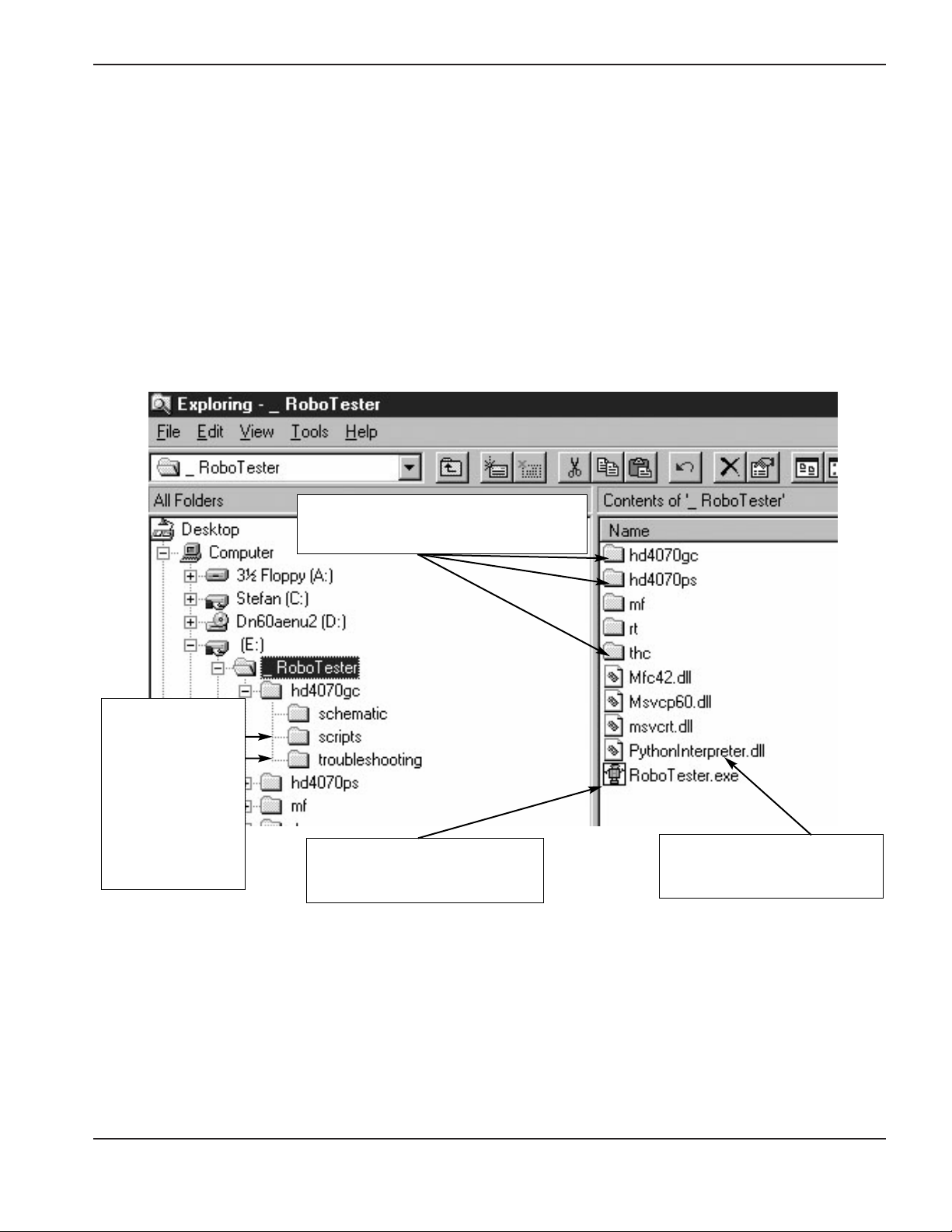
– After unzipping, you should see something like this in the Windows Explorer
Every testable machine has it’s own
folder
This is the python scripting
language engine used for test
scripts.
The actual RoboTester software.
Double click to start.
There are three
sub-folders inside
every machine
folder. The most
important ones for
the user are the
scripts and
troubleshooting
database files.
Software installation
Page 9
2-4 RoboTester Instruction Manual
SOFTWARE INSTALLATION AND OVERVIEW
0
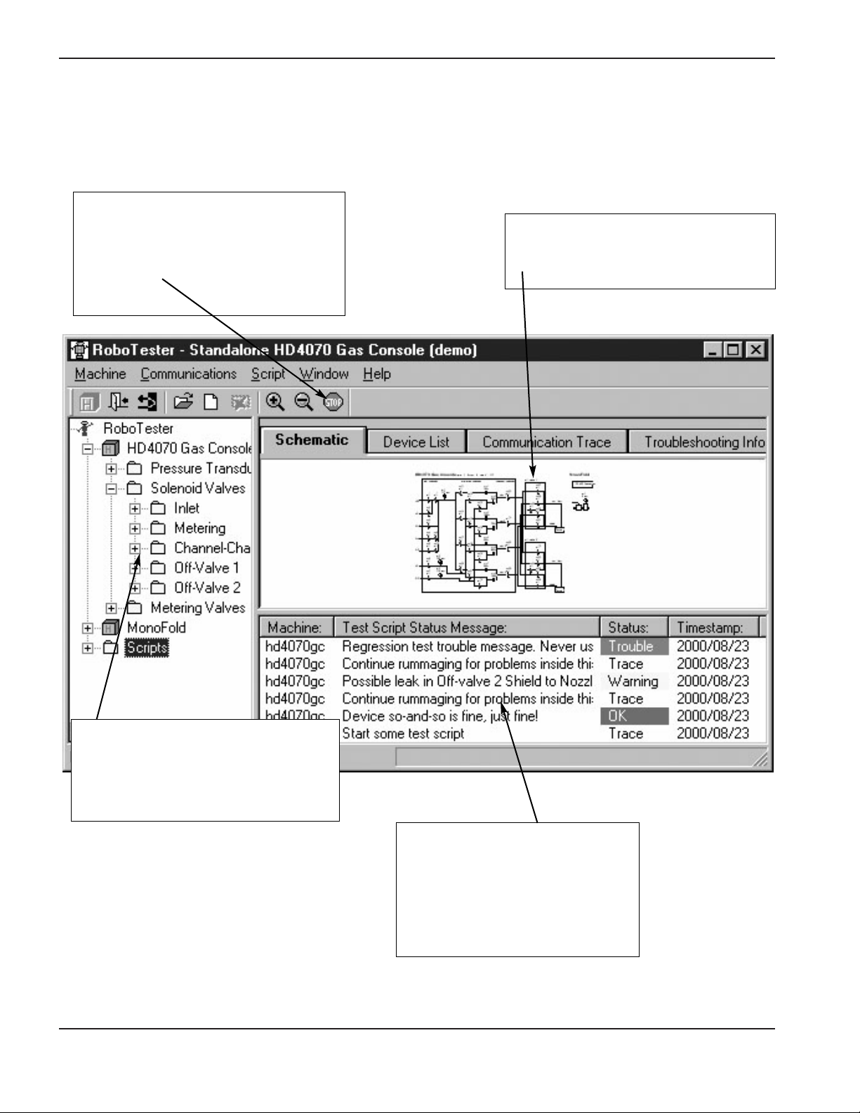
RoboTester Overview
E-Stop button
– Puts all machines in a fail-safe mode
– The “break” key (on the laptop) has the
same function
Hierarchical View
– Shows everything that is in the system:
Machines, devices, and scripts in a
“whole part” view
Trouble message view
– Shows the results of test scripts
– Lets you display troubleshooting
information, by right clicking on the
trouble message
Schematic view
– Graphically displays the most important
devices
Page 10
RoboTester Instruction Manual 2-5
SOFTWARE INSTALLATION AND OVERVIEW
0
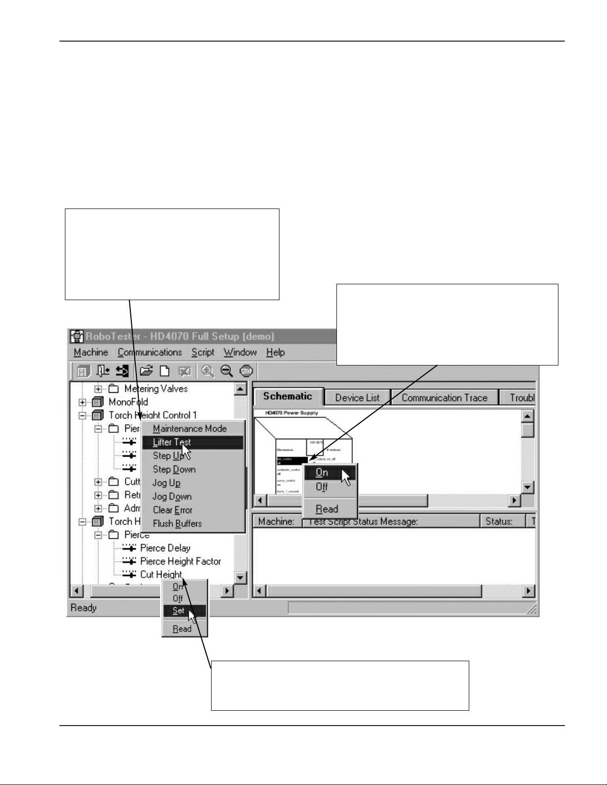
Manipulating machines and devices
In general, double-clicking or right-clicking any machine or device in the hierarchical view, the schematic view or
the device list view will let you manipulate it.
Double-clicking usually causes some “default” behavior. For an “on-off” type of device, Double-clicking will toggle it
between the on and off states.
Right click on machine in hierarchical view
– This allows you to manipulate both machines
and devices
– This can also be accomplished by right-
clicking the machine name in the schematic
view
Right-click on device in schematic view
– The fan for the power supply is shown being
turned on by the user
– The user can zoom in more to make the
devices easier to see
Right-click on device in hierarchical view
The user is setting the Cut Height. The same action can
be taken from the “device list” view
Page 11
2-6 RoboTester Instruction Manual
SOFTWARE INSTALLATION AND OVERVIEW
0
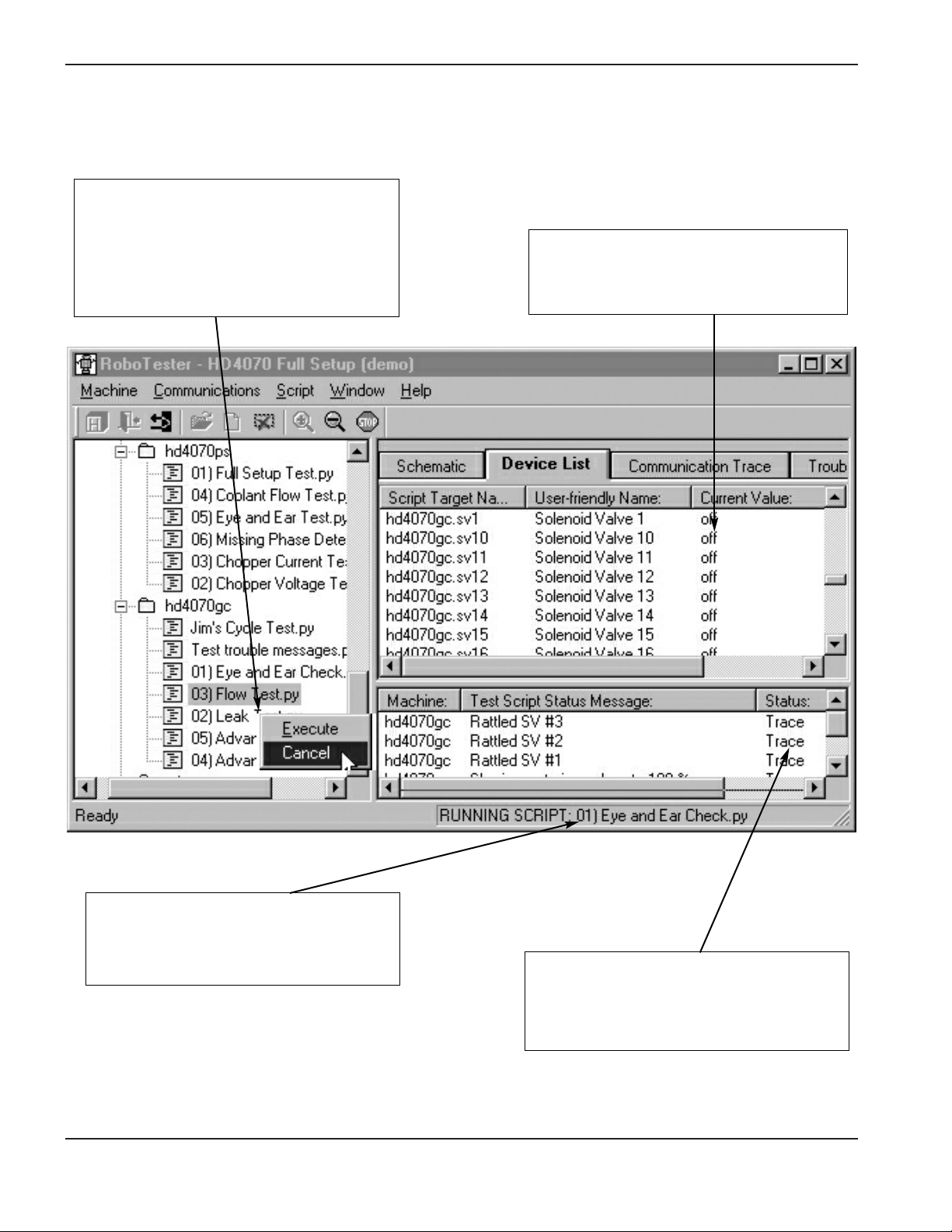
Executing test scripts
Starting and stopping a script
– Right-clicking will allow the user to turn a
script on and off. The menus or toolbar
buttons can also be used
– In the example shown: the user is stopping
the script
Viewing status changes
– The “device list” and “schematic” views will
show updated device and machine
statuses
Knowing if a script is running
– When a script is running, the status bar at
the bottom of the main window displays
it’s name
Understanding what the script is doing
– Awell written script will regularly send trace
messages to the “trouble message” view to
let the user see what it is currently doing
Page 12
RoboTester Instruction Manual 2-7
SOFTWARE INSTALLATION AND OVERVIEW
0
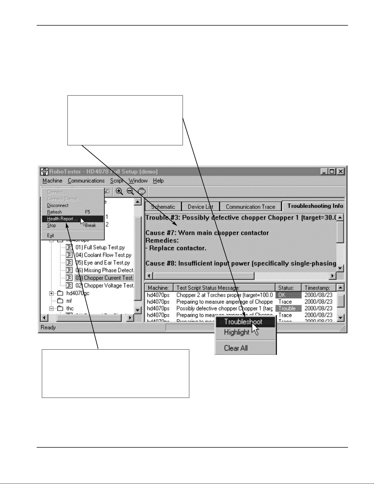
Showing troubleshooting information
– The user has right-clicked on a trouble
message, and chosen “Troubleshoot”.
The troubleshooting information is
displayed in the “troubleshooting Info”
view
Saving a “Health Report” after a script
– Choose “Health report” from the machine menu to
save the results of a script to file
– The menu item is only available if there are red,
yellow or green trouble messages available
Viewing script results
Page 13

RoboTester Instruction Manual 3-1
0
In this section:
Figure list................................................................................................................................................................3-2
System set-up ........................................................................................................................................................3-3
Robotester startup..................................................................................................................................................3-7
Stand alone gas console test ................................................................................................................................3-8
Stand alone torch height control(THC) test ..........................................................................................................3-10
Gas flow test ........................................................................................................................................................3-11
Chopper current test ............................................................................................................................................3-15
Chopper voltage test ............................................................................................................................................3-16
Coolant flow test ..................................................................................................................................................3-20
Flow switch test ....................................................................................................................................................3-21
Missing phase detect test ....................................................................................................................................3-22
Gas leak test ........................................................................................................................................................3-23
Section 3
SETUP AND OPERATION
Page 14

3-2 RoboTester Instruction Manual
SETUP AND OPERATION
0
HD4070 – Figure list
Figure 1 Satisfying interlock switches.
Figure 2 CNC dongle connection.
Figure 3 Null modem to J7 connection and disk drive location.
Figure 4 Connection of the laptop serial port to the null-modem dongle.
Figure 5 Robotester startup 1.
Figure 6 Robotester startup 2.
Figure 7 Connection of the laptop serial port to the RS-422 converter.
Figure 8 Connection of the RS-422 converter to the stand-alone gas console.
Figure 9 Connection of gas console power (VAC input).
Figure 10 Connection of the laptop serial port to the RS-422 converter.
Figure 11 Connection of the RS-422 converter to the stand-alone THC connector (J4).
Figure 12 Gas console inlet manifold connection with regulator.
Figure 13 Gas console spare I/O port for pressure transducer manifold assembly.
Figure 14 Torch slip-on cap, pressure transducer manifold assembly and calibrated orifice.
Figure 15 Torch and consumables reference for flow test.
Figure 16 Gas console with outlet manifold, pressure transducer manifold assembly and calibrated orifice.
Figure 17 I/O Board shorted out with DC short wire.
Figure 18 Chopper output (wires 39 and 48) with digital volt meter (DVM).
Figure 19 Pilot arc controller leads with DVM.
Figure 20 I/O Board with DVM.
Figure 21 Torch leads (RHF box) with DVM.
Figure 22 Torch head (electrode) with DVM.
Figure 23 Power supply with chopper fuse 1 removed.
Figure 24 Power supply with chopper fuse 2 removed.
Figure 25 Coolant return hose disconnected and placed in container for coolant flow test.
Figure 26 Connection of normal torch coolant hoses.
Figure 27 Connection of torch coolant loop-back hoses.
Figure 28 Phase loss detection board.
Figure 29 Gas console outlets for torch 1 plugged and torch 2 open.
Figure 30 Torch and torch plug for leak test.
Page 15

RoboTester Instruction Manual 3-3
SETUP AND OPERATION
0
System Set-Up: Full system or power supply only
Enables testing of the entire plasma system
Items needed: See parts list for details
#16 I/O Shunter Diskette
#25 Null Modem Dongle
#26 CNC Dongle
#29 Extension Cable
#29a optical Isolator
Set-Up
1 – Remove top and side panels from power supply.
2 – Connect the Optical Isolator to the communication port on the laptop computer.
3 – Connect Extension Cable to the Optical Isolator..
4 – Connect opposite end of Extension Cable to Null Modem Dongle.
5 – Connect Null Modem Dongle to J7 on Breakout board (PCB6).
6 – Install CNC Dongle,If no CNC cable is connected to power supply.
7 – Make sure all door switches (3) are satisfied.
8 – Insert the I/O Shunter Diskette into floppy disk drive.
9 – Turn power on HD4070 and wait until floppy disk is loaded into the HD4070 system.
WARNING
ELECTRIC SHOCK CAN KILL
Disconnect electrical power before performing any maintenance.
All work requiring removal of the power supply cover must be performed by a
qualified technician.
See Section 1 of the Operator Manual for more safety precautions.
Note: The RoboTester software is only compatible with Windows ’95, ’98 and NT.
The laptop computer being used must have a serial communication port.
Caution: Failure to use the Optical Isolator when connecting to
the laptop can cause the communication port to be
destroyed.
Page 16

3-4 RoboTester Instruction Manual
SETUP AND OPERATION
0
Satisfy the top door switch. The switch
needs to be held down flush with frame.
Satisfy the two side door switches, by
pulling them all the way out. (The second
switch is on the opposite side, not visible
in this picture)
System setup: Full system or power supply only
Figure 1 Satisfying interlock switches
Page 17

Figure 2 CNC dongle connection
RoboTester Instruction Manual 3-5
SETUP AND OPERATION
0
CNC dongle
Insert the I/O-Shunter boot diskette.
Connect null-modem cable to the J7 serial
connector, and the other end to your laptop.
System setup – continued
Figure 3 Null modem to J7 connection and disk drive location
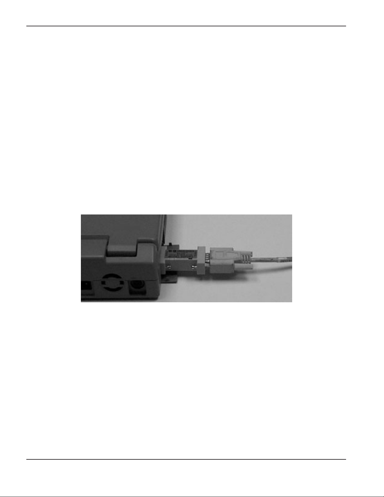
Page 18

3-6 RoboTester Instruction Manual
SETUP AND OPERATION
0
System setup – continued
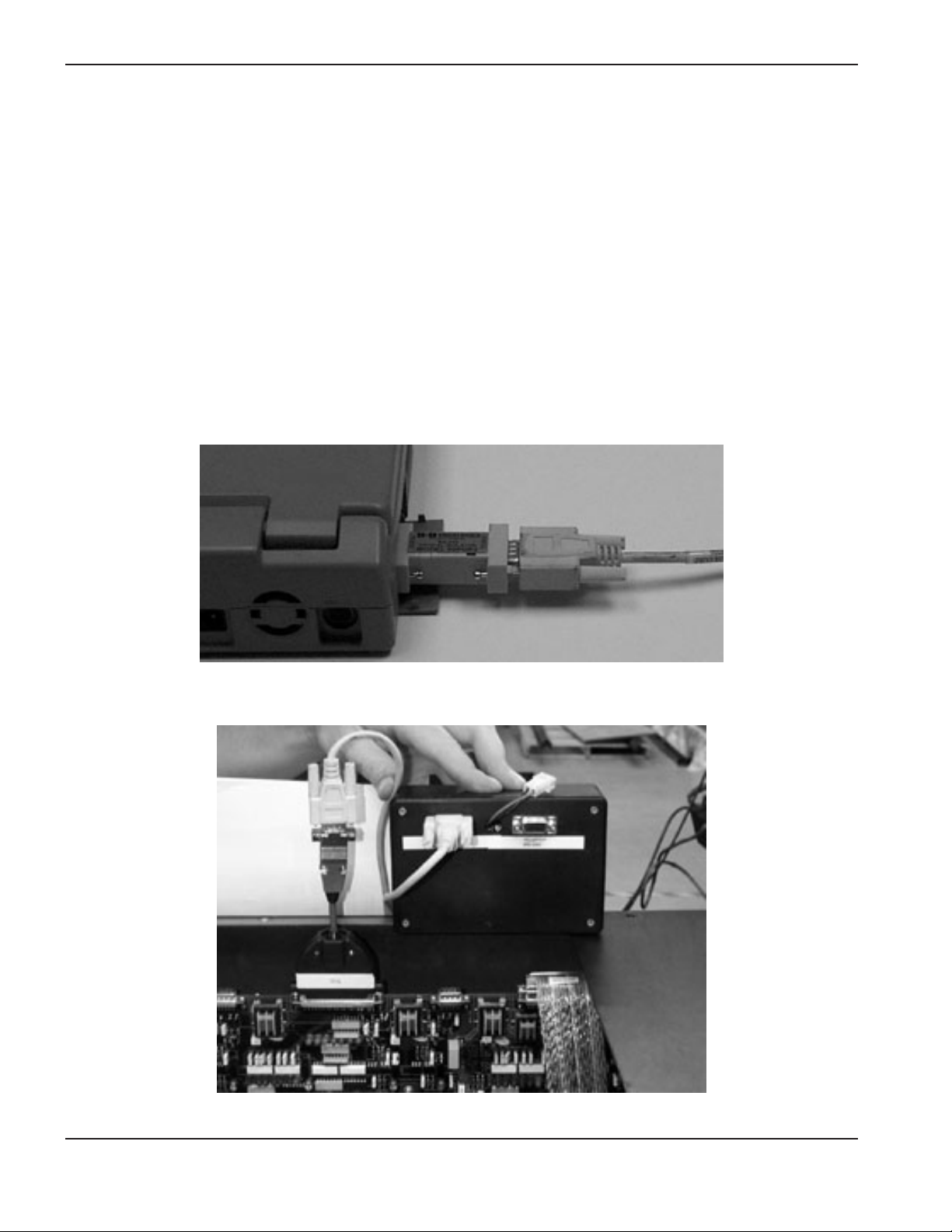
Figure 4 Connection of the laptop serial port to the null-modem dongle
Page 19
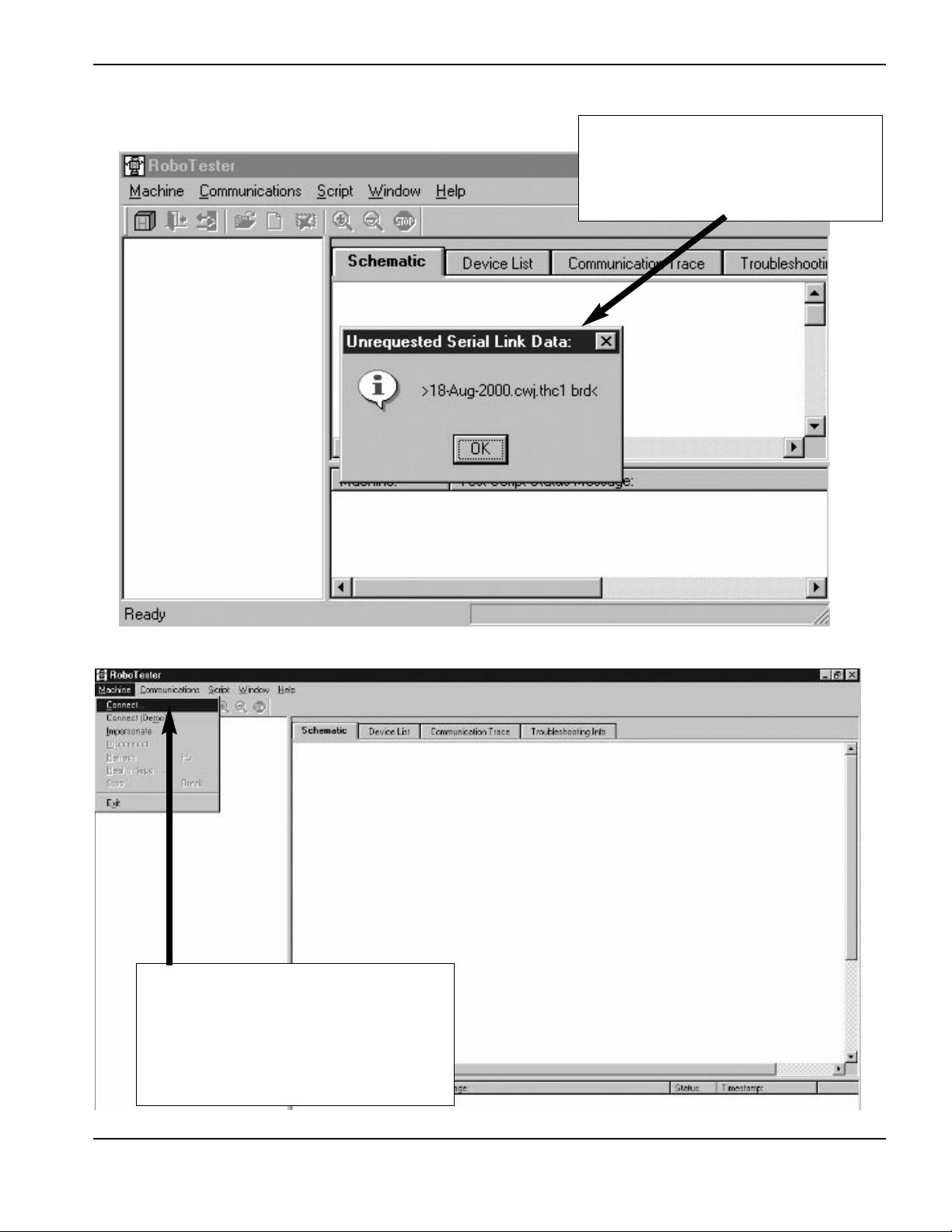
After turning the power supply ON, Wait
for the I/O-shunter to load (About 30
seconds). This message box will appear
when loading is complete.
Robotester startup
RoboTester Instruction Manual 3-7
SETUP AND OPERATION
0
Connect to “HD4070 Full Setup”. You can
now view and manipulate machines and
devices. Normally, any connection problems
will give you a red troubleshooting message.
Right click on the message for more
information.
Figure 5 Robotester startup 1
Figure 6 Robotester startup 2
Page 20
3-8 RoboTester Instruction Manual
SETUP AND OPERATION
0
Stand Alone Gas Console test
Enables testing of gas console as a stand alone unit.
Items needed: See parts list for details
#22 RS-422 Converter
#23 Gas Console Dongle
#29 Extension Cable (2)
#29a Optical Isolator
#30 Gas Console Power Cable
Set-Up
1 – Connect the Optical Isolator to the communication port on the laptop computer.
2 – Connect Extension Cable to the Optical Isolator.
3 – Connect opposite end of Extension Cable to the RS-232 port on the RS-422 Converter.
4 – Connect one end of the second Extension Cable to the RS-422 port on the RS-422 Converter.
5 – Connect opposite end of Extension Cable to Gas Console Dongle.
6 – Connect opposite end of Gas Console Dongle to 3X2 on back of Gas Console.
7 – Connect the Gas Console Power Cord to 3X1 on back of Gas Console.
Figure 7 Connection of the laptop serial port to the RS-422 converter
Page 21

RoboTester Instruction Manual 3-9
SETUP AND OPERATION
0
Figure 8 Connection of the RS-422 converter to the stand-alone gas console
Figure 9 Connection of gas console power (VAC input)
Stand alone gas console test – continued
Page 22
3-10 RoboTester Instruction Manual
SETUP AND OPERATION
0
Figure 11 Connection of the RS-422 converter to the stand-alone THC connector (J4)
Figure 10 Connection of the laptop serial port to the RS-422 converter
Stand alone THC test
Enables testing of Command THC as a stand alone unit.
Items needed: See parts list for details
#22 RS-422 Gas Console Dongle
#24 THC Dongle
#29 Extension Cable (2)
#29a Optical Isolator
Set-Up
1 – Connect the Optical Isolator to the communication port on the laptop computer.
2 – Connect Extension Cable to the Optical Isolator.
3 – Connect the other end of the extension cable to the RS-232 port on the RS-422 converter.
4 – Connect one end of the second extension cable to the RS-422 port on the RS-422 converter.
5 – Connect the other end of the second extension Cable to the THC Dongle.
6 – Connect THC Dongle to J4 on the THC Control board you want to test.
Page 23

RoboTester Instruction Manual 3-11
SETUP AND OPERATION
0
Gas flow test
Checks the gas flow from the Gas Console through the torch. Will isolate flow errors in the torch leads,
consumables, gas leads, and/or gas console.
Items Needed: See parts list for details
#3 Inert to Right Hand ‘A’ Adapter (N2)
#8 Small Orifice Assembly
#9 Large Orifice Assembly
#10 100A Mild Steel Nozzle/Shield Assembly
#1 1 100A Swirl-ring Assembly
#11a 100A Electrode
#17 Inlet Manifold Assembly
#18 Slip-on Torch Cap Assembly
#19 Regulator Assembly
#21 Pressure Transducer Manifold Assembly
#32 Right Hand ‘A’ Hose Assembly (2)
Set-Up
1 – Install Inlet manifold assembly to Inlet manifold of gas console.
2 – Connect input hose of the inlet manifold to the outlet side of the regulator assembly.
3 – Connect one of the hose assemblies to the inlet side of the regulator assembly.
4 – Connect the other end of the hose assembly to the Inert Adapter.
5 – Connect the nitrogen supply line into the inert adapter.
6 – Install the 100A consumable parts into the torch.
7 – Install the slip-on torch cap assembly to the end of the torch. Make sure thumb screws tighten into the groove
on the retaining cap.
8 – Connect hose end of the torch cap assembly to the pressure transducer manifold assembly. Make sure the
shut-off lever is in the ON position.
9 – Connect the second hose assembly to the pressure transducer manifold.
10 – Connect opposite end of the Hose Assembly to the large orifice assembly.
11 – Connect Pressure Transducer Manifold Assembly cable to J2 on the gas console board (PCB2).
12 – Set pressure at regulator assembly to 100 psi (6.9 bar). Set gas pressure at source (N2) to 120 psi (7.3 bar).
Before running the gas flow test, check the calibration of the 4 pressure transducers.
To check the calibration perform the following functions:
1 – Turn the gas shut-off lever on the pressure transducer manifold to the OFF position.
2 – Manually turn SV5, SV10, SV11, SV12, SV13, and SV23 ON.
3 – Read the pressure for PT1, PT2, PT3 and PT4.
4 – Values should be within +/- 2psi of each other.
If values are not within specification, call Hypertherm technical service for PCB2 calibration procedure.
Page 24
3-12 RoboTester Instruction Manual
SETUP AND OPERATION
0
Gas flow test – continued
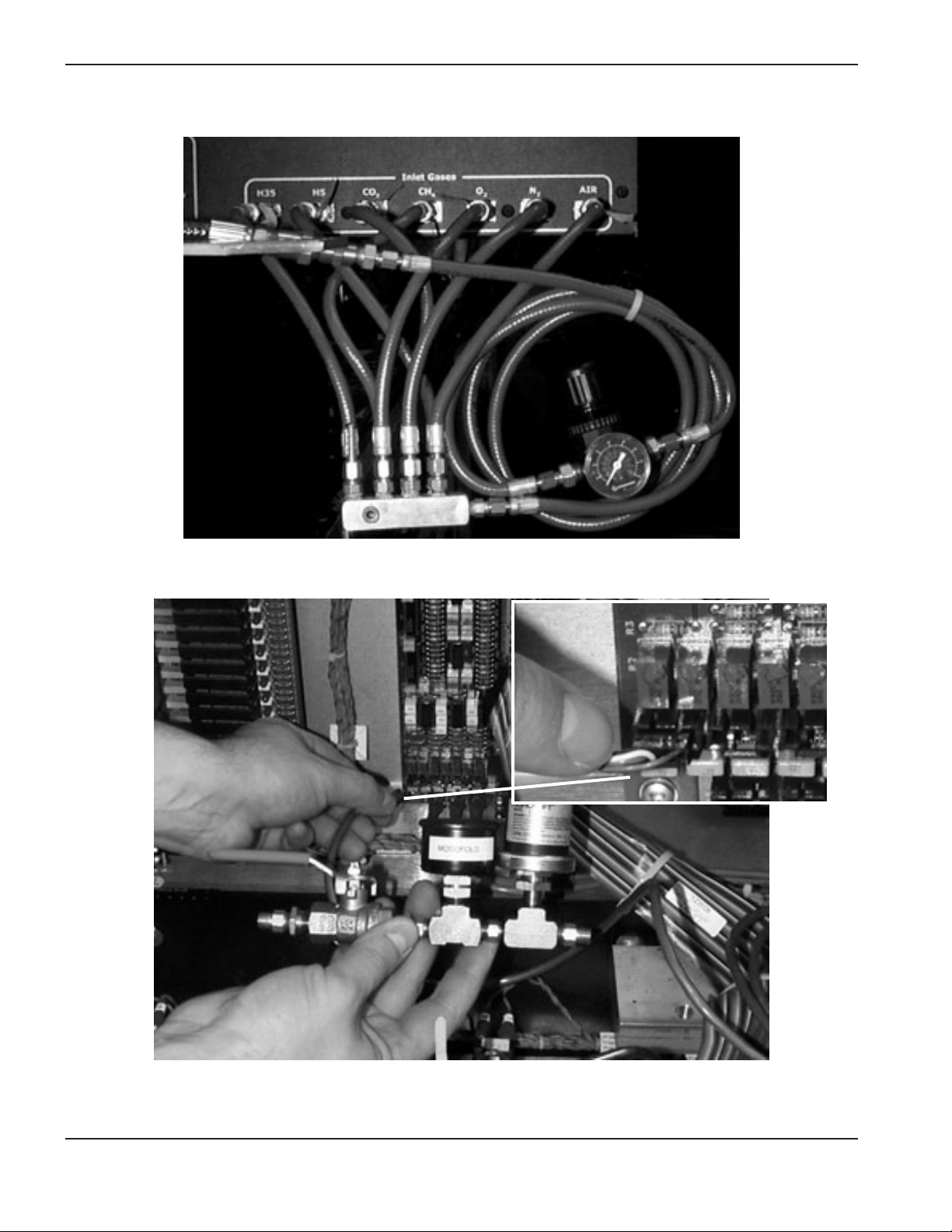
Figure 12 Gas console inlet manifold connection with regulator
Figure 13 Gas console spare I/O port for pressure transducer manifold assembly
Page 25
RoboTester Instruction Manual 3-13
SETUP AND OPERATION
0
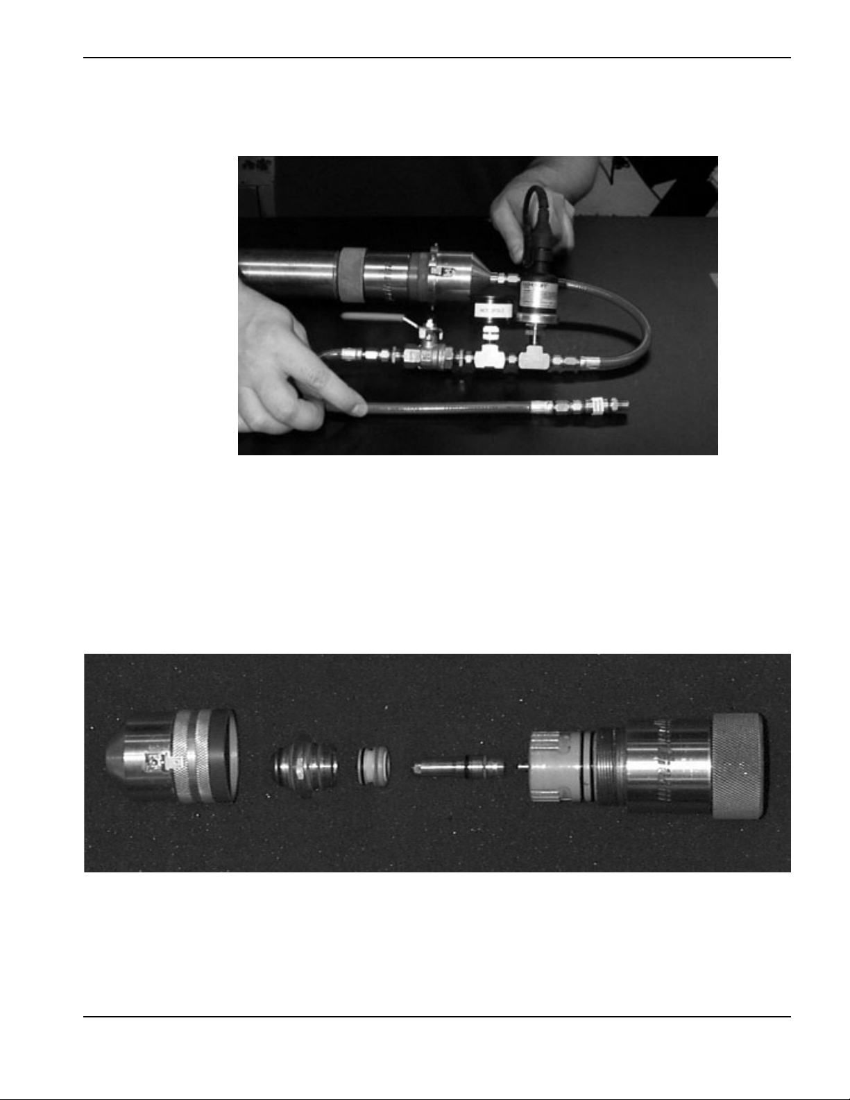
Figure 14 Torch slip-on cap, pressure transducer manifold and calibrated orifice
Figure 15 Torch and consumables reference for flow test
Gas flow test – continued
Page 26

3-14 RoboTester Instruction Manual
SETUP AND OPERATION
0
Figure 16 Gas console with outlet manifold, pressure transducer manifold assembly, and calibrated orifice
Gas flow test – continued
Page 27

RoboTester Instruction Manual 3-15
SETUP AND OPERATION
0
Figure 17 I/O Board shorted out with DC short wire
Chopper current test
Checks the current output of each chopper. Chopper 1 is tested a 30-amps and Chopper 2 is tested at 100-amps.
If proper current is detected the choppers are functioning properly.
Items Needed: See parts list for details
#1 4/O Jumper Cable
Set-Up
1 – Remove Negative and Work Lead 4/O cables from large brass bus bars inside HD4070
2 – Install 4/O Jumper Cable across buss bars in place of Negative and Work Leads
Page 28

3-16 RoboTester Instruction Manual
SETUP AND OPERATION
0
Chopper voltage test
Checks the open circuit voltage at various points in the plasma system.
Items Needed:
Digital Volt Meter – Not included in kit
Figure 18 output (wires 39 and 48) with digital volt meter (DVM)
Figure 19 Pilot arc controller leads with DVM
Page 29

RoboTester Instruction Manual 3-17
SETUP AND OPERATION
0
Figure 20 I/O Board with DVM
Figure 21 Torch leads (RHF box) with DVM
Chopper voltage test – continued
Page 30

3-18 RoboTester Instruction Manual
SETUP AND OPERATION
0
Figure 22 Torch head (electrode) with DVM
Figure 23 Power supply with chopper fuse 1 removed
Chopper voltage test – continued
Page 31

RoboTester Instruction Manual 3-19
SETUP AND OPERATION
0
Figure 24 Power supply with chopper fuse 2 removed
Chopper voltage test – continued
Page 32

3-20 RoboTester Instruction Manual
SETUP AND OPERATION
0
Figure 25 Coolant return hose disconnected and placed in container for coolant flow test
Coolant flow test
Tests total coolant flow through each torch.
Items Needed:
1 Gallon Container – Not included in kit
Figure 26 Connection of normal torch coolant hoses
Page 33
RoboTester Instruction Manual 3-21
SETUP AND OPERATION
0
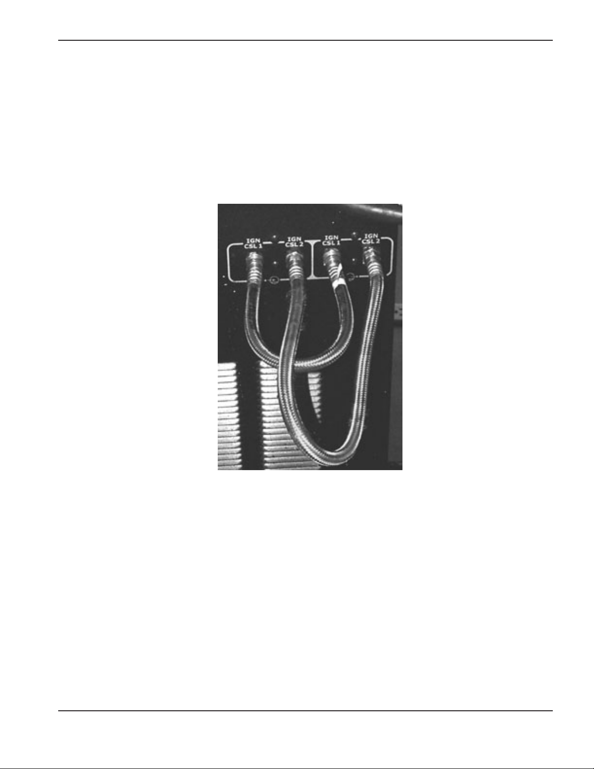
Figure 27 Connection of torch coolant loop-back hoses
Flow switch test
Tests the flow-switch by bypassing the torch and .
Items Needed: See parts list for details
#33 Coolant loop-back hose
Set-Up
1 – Install coolant loop-back hose in place of the torch coolant hoses for the torch that is being tested.
Page 34

3-22 RoboTester Instruction Manual
SETUP AND OPERATION
0
Missing phase detect test
Tests the three phases on the secondary side of the main transformer.
Items Needed:
None
Figure 28 Phase loss detection board
Page 35

RoboTester Instruction Manual 3-23
SETUP AND OPERATION
0
Gas leak test
Checks for leaks from the torch to the gas console. Test is designed to locate leaks inside the gas console, or at
the torch.
Items Needed: See parts list for details
#3 Inert to right hand ‘A’ adapter (N2)
#12 Right hand ‘A’ plug (2)
#13 Left hand ‘A’ plug (2)
#14 Torch receptacle plug
#17 Inlet manifold assembly
#19 Regulator assembly
#32 Right hand ‘A’ hose assembly
Set-Up
1 – Remove all gas supply lines from the back of the gas console.
2 – Install inlet manifold to the gas console.
3 – Install outlet of regulator assembly to inlet manifold assembly.
4 – Install one end of the hose assembly to inlet side of the pressure regulator assembly.
5 – Install the other end of the hose to the inert adapter (N2).
6 – Connect the N2supply line to the inert adapter.
7 – Set pressure at regulator assembly to 100 psi (6.9 bar). Set gas pressure at source (N2) to 120 psi (7.3 bar).
Page 36

3-24 RoboTester Instruction Manual
SETUP AND OPERATION
0
Figure 29 Gas console outlets for torch 1 plugged and torch 2 open
Figure 30 Torch and torch plug for leak test
Gas leak test – continued
Page 37

RoboTester Instruction Manual 4-1
0
In this section:
Parts list – Items 1-16...............................................................................................................................................4-2
Parts list – Items 17-21.............................................................................................................................................4-3
Parts list – Items 22-33.............................................................................................................................................4-4
Parts list – Items 34-40.............................................................................................................................................4-5
Section 4
PARTS LIST
Page 38

4-2 RoboTester Instruction Manual
PARTS LIST
0
Parts list – Items 1-16
This list of hardware is not final, but gives a good idea of what the kit should contain
10
987654321
3
Part
Item Number Description Qty
1 123624 Cable to short circuit I/O board 1
2 128584 Adapter: Left hand ‘B’ to right hand ‘A’ 3
3 128585 Adapter: Inert to right hand ’A’ 2
4 128587 Adapter: Right hand ‘B’ to right hand ‘A’ 1
5 128586 Adapter: #6 to right hand ‘A’ 1
6 128593 Adapter: Right hand ‘A’ to quick disconnect 1
7 128590 Medium (.024") orifice assembly 1
8 128591 Small (.014") orifice assembly 1
9 128592 Large (.030”) orifice assembly 1
10 120660 100A mild steel nozzle/shield assembly 1
11 120783 100A Swirl ring 1
11a 120654 100A Electrode 1
12 004918 Right hand ‘A’ plug 8
13 004917 Left hand ‘A’ plug 4
14 129671 Torch receptacle plug 1
15 081069 RoboTester software 1
16 081070 I/O shunter diskette (2 copies provided) 2
12
131416
15
11
11
a
Page 39

RoboTester Instruction Manual 4-3
PARTS LIST
0
Parts list – Items 17-21
17
21
18
19
20
Part
Item Number Description Qty
17 128597 Inlet manifold assembly 1
18 128581 Slip-on torch cap assembly 1
19 128594 Regulator assembly 1
20 128617 Outlet manifold assembly 1
21 128582 Pressure transducer manifold assembly 1
Page 40
4-4 RoboTester Instruction Manual
PARTS LIST
0
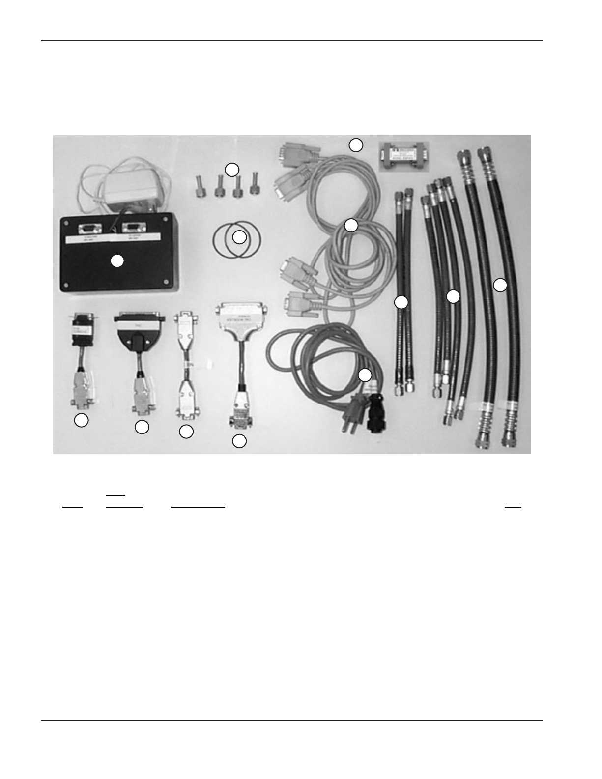
Parts list – Items 22-33
30
29
28272625232224
Part
Item Number Description Qty
22 128614 RS-422 converter 1
23 123626 Gas console dongle 1
24 123625 THC dongle 1
25 123628 Null modem dongle 1
26 123629 CNC dongle 1
27 004944 1/4" compression plugs 4
28 044548 Replacement o-rings for slip-on cap 2
29 123632 9 pin extension cable 2
29a 108258 Optical Isolator 1
30 129698 Gas console power cord 1
31 024710 Hose assembly: 3/16 inch right hand to 3/16 inch left hand 2
32 024711 Hose assembly: 3/16 inch right hand ‘A’ 6
33 024162 Coolant loop-back hose: 1/2 inch #8 2
29
a
33
31
32
Page 41

RoboTester Instruction Manual 4-5
PARTS LIST
0
Parts list – Items 34-40
Part
Item Number Description Qty
34 128588 Adapter: Left hand ‘A’ male to right hand ‘A’female 4
35 220002 Ignition testing: Cap 1
36 220003 Ignition testing: Nozzle 1
37 220004 Ignition testing: Electrode 1
38 128604 Ignition testing: Torch receptacle 1
39 804010 RoboTester instruction manual 1
40 001782 RoboTester tool box (not shown) 1
34
35
38
36
39
37
 Loading...