

Page 1

Plasma Arc
Cutting System
Service Manual
803150 - Revision 3
®
EN50199
EN50192
Page 2

Plasma Arc Cutting System
Service Manual
IM-315
(P/N 803150)
for systems beginning with serial number
900-010000
Revision 3 June, 2000
Hypertherm, Inc.
Hanover, NH
http://www.hypertherm.com
email:info@hypertherm.com
© Copyright 2000 Hypertherm, Inc.
All Rights Reserved
Hypertherm and Powermax are trademarks of Hypertherm, Inc.,
and may be registered in the United States and/or other countries
Page 3

Hypertherm Offices Worldwide
Hypertherm, Inc.
Etna Road, P.O. Box 5010
Hanover, NH 03755 USA
Tel.: (603) 643-3441 (Main Office)
Fax: (603) 643-5352 (All Departments)
Tel.: (800) 643-9878 (Technical Service – toll-free in USA and Canada)
Tel.: (800) 737-2978 (Customer Service – toll-free in USA and Canada)
email: info@hypertherm.com (General Information)
email: service@hypertherm.com (Technical/Customer Services)
Hypertherm Plasmatechnik GmbH
Technologiepark Hanau
Rodenbacher Chaussee 6
D–63457 Hanau-Wolfgang, Germany
Tel.: 49 6181 58 2100
Fax: 49 6181 58 2134
Hypertherm (S) Pte Ltd
No. 19 Kaki Bukit Road 2
K.B. Warehouse Complex
Singapore 417847
Tel.: 65 841 2489
Fax: 65 841 2490
Hypertherm UK Ltd
9 Berkeley Court, Manor Park
Runcorn, Cheshire, England WA7 1TQ
Tel.: 44 1928 579 074
Fax: 44 1928 579 604
:
France
15 Impasse des Rosiers
95610 Eragny, France
Tel.: 33 1 30 37 15 28
Fax: 33 1 30 37 15 79
Hypertherm S.r.L.
Via Torino 2
20123 Milan, Italy
Tel.: 39 02 725 46 312 (Customer Service)
Tel.: 39 02 725 46 314 (Technical Service)
Fax: 39 02 725 46 400 (All Departments)
Hypertherm B.V.
Burg, Haverkampstraat 13
7091 CN Dinxperlo, The Netherlands
Tel.: 31 315 655 866 (Customer Service)
Fax: 31 315 655 886
European Technical Support Organization (ETSO)
Edisonstraat 12
3281 NC Numansdorp, The Netherlands
Tel.: 00 800 4973 7843 (00 800 Hypertherm) – (toll-free Technical Service)
Tel.: 31 186 659494
Fax: 31 186 659495
Japan
Shinjuku Park Tower
30th Floor
3-7-1 Nishi-Shinjuku
Shinjuku-ku, Tokyo
163-1030, Japan
Tel.: 81 03 5326 3142
Fax: 81 03 5326 3001
5/00
Page 4

ELECTROMAGNETIC COMPATIBILITY
EMC INTRODUCTION
Hypertherm's CE-marked equipment is
built in compliance with standard
EN50199. The equipment should be
installed and used in accordance with the
information below to achieve
electromagnetic compatibility.
The limits required by EN50199 may not
be adequate to completely eliminate
interference when the affected equipment
is in close proximity or has a high degree
of sensitivity. In such cases it may be
necessary to use other measures to
further reduce interference.
This plasma is designed for use only in an
industrial environment.
INSTALLATION AND USE
The user is responsible for installing and
using the plasma equipment according to
the manufacturer's instructions. If
electromagnetic disturbances are
detected then it shall be the responsibility
of the user to resolve the situation with the
technical assistance of the manufacturer.
In some cases this remedial action may be
as simple as earthing the cutting circuit,
see
Earthing of Workpiece
it could involve constructing an
electromagnetic screen enclosing the
power source and the work complete with
associated input filters. In all cases
electromagnetic disturbances must be
reduced to the point where they are no
longer troublesome.
ASSESSMENT OF AREA
Before installing the equipment the user
shall make an assessment of potential
electromagnetic problems in the
surrounding area. The following shall be
taken into account:
a. Other supply cables, control cables,
signalling and telephone cables; above,
below and adjacent to the cutting
equipment.
b. Radio and television transmitters and
receivers.
c. Computer and other control equipment.
d. Safety critical equipment, for example
guarding of industrial equipment.
e. Health of the people around, for
example the use of pacemakers and
hearing aids.
f. Equipment used for calibration or
measurement.
. In other cases
g. Immunity of other equipment in the
environment. User shall ensure that
other equipment being used in the
environment is compatible. This may
require additional protection measures.
h. Time of day that cutting or other
activities are to be carried out.
The size of the surrounding area to be
considered will depend on the structure of
the building and other activities that are
taking place. The surrounding area may
extend beyond the boundaries of the
premises.
METHODS OF REDUCING
EMISSIONS
Mains Supply
Cutting equipment must be connected to
the mains supply according to the
manufacturer's recommendations. If
interference occurs, it may be necessary
to take additional precautions such as
filtering of the mains supply.
Consideration should be given to
shielding the supply cable of permanently
installed cutting equipment, in metallic
conduit or equivalent. Shielding should
be electrically continuous throughout its
length. The shielding should be
connected to the cutting mains supply so
that good electrical contact is maintained
between the conduit and the cutting
power source enclosure.
Maintenance of Cutting Equipment
The cutting equipment must be routinely
maintained according to the
manufacturer's recommendations. All
access and service doors and covers
should be closed and properly fastened
when the cutting equipment is in
operation. The cutting equipment should
not be modified in any way except for
those changes and adjustments covered
in the manufacturer's instructions. In
particular, the spark gaps of arc striking
and stabilizing devices should be
adjusted and maintained according to the
manufacturer's recommendations.
Cutting Cables
The cutting cables should be kept as
short as possible and should be
positioned close together, running at or
close to the floor level.
Equipotential Bonding
Bonding of all metallic components in the
cutting installation and adjacent to it
should be considered. However, metallic
components bonded to the workpiece will
increase the risk that the operator could
receive a shock by touching these
metallic components and the electrode at
the same time. The operator should be
insulated from all such bonded metallic
components.
Earthing of Workpiece
Where the workpiece is not bonded to
earth for electrical safety, nor connected
to earth because of its size and position,
for example, ship's hull or building
steelwork, a connection bonding the
workpiece to earth may reduce
emissions in some, but not all instances.
Care should be taken to prevent the
earthing of the workpiece increasing the
risk of injury to users, or damage to other
electrical equipment. Where necessary,
the connection of the workpiece to earth
should be made by a direct connection to
the workpiece, but in some countries
where direct connection is not permitted,
the bonding should be achieved by
suitable capacitances selected
according to national regulations.
Note: The cutting circuit may or may not
be earthed for safety reasons. Changing
the earthing arrangements should only
be authorized by a person who is
competent to assess whether the
changes will increase the risk of injury, for
example, by allowing parallel cutting
current return paths which may damage
the earth circuits of other equipment.
Further guidance is given in IEC TC26
(sec)94 and IEC TC26/108A/CD Arc
Welding Equipment Installation and Use.
Screening and Shielding
Selective screening and shielding of
other cables and equipment in the
surrounding area may alleviate problems
of interference. Screening of the entire
plasma cutting installation may be
considered for special applications.
Service Manual
i
Page 5

W
ARRANTY
WARNING
Genuine Hypertherm parts are the factory-recommended
replacement parts for your Hypertherm system. Any
damage caused by the use of other than genuine
Hypertherm parts may not be covered by the Hypertherm
warranty.
WARNING
You are responsible for the safe use of the Product.
Hypertherm does not and cannot make any guarantee or
warranty regarding the safe use of the Product in your
environment.
GENERAL
Hypertherm, Inc. warrants that its Products shall be free
from defects in materials and workmanship, if Hypertherm
is notified of a defect (i) with respect to the power supply
within a period of two (2) years from the date of its delivery
to you, and (ii) with respect to the torch and leads within a
period of one (1) year from its date of delivery to you. This
warranty shall not apply to any Product which has been
incorrectly installed, modified, or otherwise damaged.
Hypertherm, at its sole option, shall repair, replace, or
adjust, free of charge, any defective Products covered by
this warranty which shall be returned with Hypertherm’s
prior authorization (which shall not be unreasonably
withheld), properly packed, to Hypertherm’s place of
business in Hanover, New Hampshire, or to an authorized
Hypertherm repair facility, all costs, insurance and freight
prepaid. Hypertherm shall not be liable for any repairs,
replacement, or adjustments of Products covered by this
warranty, except those made pursuant to this paragraph or
with Hypertherm’s prior written consent. The warranty
above is exclusive and is in lieu of all other warranties,
express, implied, statutory, or otherwise with respect
to the Products or as to the results which may be
obtained therefrom, and all implied warranties or
conditions of quality or of merchantability or fitness for
a particular purpose or against infringement. The
foregoing shall constitute the sole and exclusive
remedy for any breach by Hypertherm of its warranty.
Distributors/OEMs may offer different or additional
warranties, but Distributors/OEMs are not authorized to
give any additional warranty protection to you or make any
representation to you purporting to be binding upon
Hypertherm.
formulae, or combinations not developed or purported to be
developed by Hypertherm, Hypertherm will defend or
settle, at its own expense, any suit or proceeding brought
against you alleging that the use of the Hypertherm
product, alone and not in combination with any other
product not supplied by Hypertherm, infringes any patent of
any third party. You shall notify Hypertherm promptly upon
learning of any action or threatened action in connection
with any such alleged infringement, and Hypertherm’s
obligation to indemnify shall be conditioned upon
Hypertherm’s sole control of, and the indemnified party’s
cooperation and assistance in, the defense of the claim.
LIMITATION OF LIABILITY
In no event shall Hypertherm be liable to any person or
entity for any incidental, consequential, indirect, or
punitive damages (including but not limited to lost
profits) regardless of whether such liability is based on
breach of contract, tort, strict liability, breach of
warranties, failure of essential purpose or otherwise
and even if advised of the possibility of such damages.
LIABILITY CAP
In no event shall Hypertherm’s liability, whether such
liability is based on breach of contract, tort, strict
liability, breach of warranties, failure of essential
purpose or otherwise, for any claim action suit or
proceeding arising out of or relating to the use of the
Products exceed in the aggregate the amount paid for
the Products that gave rise to such claim.
INSURANCE
At all times you will have and maintain insurance in such
quantities and types, and with coverage sufficient and
appropriate to defend and to hold Hypertherm harmless in
the event of any cause of action arising from the use of the
Products.
NATIONAL AND LOCAL CODES
National and Local codes governing plumbing and
electrical installation shall take precedent over any
instructions contained in this manual. In no event shall
Hypertherm be liable for injury to persons or property
damage by reason of any code violation or poor work
practices.
PATENT INDEMNITY
Except only in cases of products not manufactured by
Hypertherm or manufactured by a person other than
Hypertherm not in strict conformity with Hypertherm’s
specifications and in cases of designs, processes,
TRANSFER OF RIGHTS
You may transfer any remaining rights you may have
hereunder only in connection with the sale of all or
substantially all of your assets or capital stock to a
successor in interest who agrees to be bound by all of the
terms and conditions of this Warranty.
ii Hypertherm Warranty
5-00
Page 6

TABLE OF CONTENTS
ELECTROMAGNETIC COMPATIBILITY ............................................................................................... i
WARRANTY...........................................................................................................................................ii
Section 1 Safety ................................................................................................ 1-1
RECOGNIZE SAFETY INFORMATION ............................................................................................. 1-2
FOLLOW SAFETY INSTRUCTIONS ................................................................................................. 1-2
CUTTING CAN CAUSE FIRE OR EXPLOSION ................................................................................ 1-2
ELECTRIC SHOCK CAN KILL........................................................................................................... 1-2
CUTTING CAN PRODUCE TOXIC FUMES ......................................................................................1-3
ARC RAYS CAN BURN EYES AND SKIN......................................................................................... 1-4
COMPRESSED GAS EQUIPMENT SAFETY.................................................................................... 1-4
ADDITIONAL SAFETY INFORMATION ............................................................................................. 1-4
NOISE CAN DAMAGE HEARING ..................................................................................................... 1-4
GAS CYLINDERS CAN EXPLODE IF DAMAGED ............................................................................1-4
GROUNDING SAFETY ...................................................................................................................... 1-5
PLASMA ARC CAN CAUSE INJURY AND BURNS .......................................................................... 1-5
PACEMAKER AND HEARING AID OPERATION .............................................................................. 1-5
Section 1a Sécurité .......................................................................................... 1a-1
IDENTIFIER LES CONSIGNES DE SÉCURITÉ.............................................................................. 1a-2
SUIVRE LES INSTRUCTIONS DE SÉCURITÉ ............................................................................... 1a-2
LE COUPAGE PEUT PROVOQUER UN INCENDIE OU UNE EXPLOSION .................................. 1a-2
DANGER AVERTISSEMENT PRÉCAUTION ................................................................................ 1a-2
LE COUPAGE PEUT PRODUIRE DES VAPEURS TOXIQUES...................................................... 1a-3
LES CHOCS ÉLECTRIQUES PEUVENT ÊTRE FATALS................................................................ 1a-3
L’ARC PLASMA PEUT PROVOQUER DES BLESSURES OU DES BRÛLURES .......................... 1a-4
MISE À LA MASSE ET À LA TERRE............................................................................................... 1a-4
LES RAYONS DE L’ARC PEUVENT BRÛLER LES YEUX ET LA PEAU ........................................ 1a-4
SÉCURITÉ DES BOUTEILLES DE GAZ COMPRIMÉ .................................................................... 1a-5
LE BRUIT PEUT PROVOQUER DES PROBLÈMES AUDITIFS ..................................................... 1a-5
PACEMAKERS ET PROTHÈSES AUDITIVES................................................................................ 1a-5
LES BOUTEILLES DE GAZ COMPRIMÉ PEUVENT EXPLOSER EN CAS DE DOMMAGES ....... 1a-5
Section 2 SPECIFICATIONS............................................................................. 2-1
INTRODUCTION................................................................................................................................ 2-2
SPECIFICATIONS ............................................................................................................................. 2-3
Power Supply .............................................................................................................................. 2-3
PAC125 TORCHES ........................................................................................................................... 2-4
PAC125T Hand Torch Assembly.................................................................................................. 2-4
PAC125M Machine Torch Assembly ............................................................................................ 2-4
S MARK ........................................................................................................................................... 2-5
SETUP SPECIFICATIONS ................................................................................................................ 2-5
Power Cord Plugs........................................................................................................................ 2-5
Power Cords ................................................................................................................................ 2-5
208/240/480/600V Power Supplies ............................................................................................. 2-5
200/230/400V Power Supplies .................................................................................................... 2-5
Power Requirements ................................................................................................................... 2-6
Service Manual
iii
Page 7

TABLE OF CONTENTS
Section 3 MAINTENANCE.................................................................................... 3-1
INTRODUCTION................................................................................................................................ 3-2
ROUTINE MAINTENANCE ................................................................................................................ 3-2
Bowl Draining/Filter Element Cleaning ........................................................................................ 3-2
Removal, Cleaning and Replacement of the Cooling Air Filter.................................................... 3-3
CONTROLS AND INDICATORS ........................................................................................................ 3-4
THEORY OF OPERATION ................................................................................................................ 3-5
General ........................................................................................................................................ 3-5
Functional Description ................................................................................................................. 3-6
SEQUENCE OF OPERATION ........................................................................................................... 3-7
TROUBLESHOOTING .......................................................................................................................3-8
Test Equipment ............................................................................................................................ 3-8
Troubleshooting Procedures........................................................................................................ 3-8
Visual Inspection - External ......................................................................................................... 3-8
Visual Inspection - Internal .......................................................................................................... 3-9
Resistance Checks .................................................................................................................... 3-10
POWERMAX900 TROUBLESHOOTING GUIDE ............................................................................ 3-13
Voltage Checks.......................................................................................................................... 3-18
Power Board Test Points ........................................................................................................... 3-22
POWER BOARD .............................................................................................................................. 3-22
CONTROL BOARD .......................................................................................................................... 3-24
Control Board LEDs................................................................................................................... 3-24
PAC125T TORCH PARTS REMOVAL AND REPLACEMENT ......................................................... 3-26
Torch Main Body Removal and Replacement ........................................................................... 3-26
Torch Switch Removal and Replacement .................................................................................. 3-27
PAC125M TORCH PARTS REMOVAL AND REPLACEMENT ........................................................ 3-28
Removal .................................................................................................................................... 3-28
Replacement ............................................................................................................................. 3-28
QUICK DISCONNECT O-RING REMOVAL AND REPLACEMENT ................................................ 3-30
Section 4 PARTS LIST – 208/240/480V ............................................................. 4-1
POWER SUPPLY - 208/240/480V ..................................................................................................... 4-2
Front ............................................................................................................................................ 4-2
Top and Right Side ...................................................................................................................... 4-4
Bottom and Left Side ................................................................................................................... 4-6
Rear ............................................................................................................................................. 4-8
Powermax900 Field Upgrade Kits and Optional Parts .............................................................. 4-10
POWER SUPPLIES - 208/240/480V, 1F/3F, 60 HZ ......................................................................... 4-10
RECOMMENDED SPARE PARTS - POWERMAX900- 208/240/480V ........................................... 4-11
Section 5 PARTS LIST - 200/230/400V .............................................................. 5-1
POWER SUPPLY - 200/230/400V ..................................................................................................... 5-2
Front ............................................................................................................................................ 5-2
Top and Right Side ...................................................................................................................... 5-4
Bottom and Left Side ................................................................................................................... 5-6
Rear ............................................................................................................................................. 5-8
Powermax900 Field Upgrade Kits and Optional Parts .............................................................. 5-10
POWER SUPPLIES - 200/230/400V, 1F/3F, 50/60 HZ .................................................................... 5-10
RECOMMENDED SPARE PARTS - POWERMAX900- 200/230/400V ........................................... 5-11
iv
Service Manual
Page 8

TABLE OF CONTENTS
Section 6 PARTS LIST - 400V CE ...................................................................... 6-1
POWER SUPPLY - 400V CE ............................................................................................................. 6-2
Front ............................................................................................................................................ 6-2
Top and Right Side ...................................................................................................................... 6-4
Bottom and Left Side ................................................................................................................... 6-6
Rear ............................................................................................................................................. 6-8
Powermax900 Field Upgrade Kits and Optional Parts .............................................................. 6-10
POWER SUPPLIES - 400V CE, 3F, 50 HZ...................................................................................... 6-10
RECOMMENDED SPARE PARTS - POWERMAX900 400V CE .................................................... 6-11
Section 7 PARTS LIST - TORCHES AND CONSUMABLES ........................... 7-1
PAC125T Torch Assembly and 25 ft (7.6 m) Lead - 083066........................................................ 7-2
PAC125T Torch Assembly and 50 ft (15.2 m) Lead - 083067...................................................... 7-2
PAC125M Torch Assembly and 14 ft (4.3 m) Lead - 083069 w/pigtail, 083073 no pigtail ........... 7-3
PAC125M Torch Assembly and 25 ft (7.6 m) Lead - 083068 w/pigtail, 083072 no pigtail ........... 7-3
PAC125M Torch Assembly and 35 ft (10.6 m) Lead - 083070 w/pigtail, 083074 no pigtail ......... 7-3
PAC125M Torch Assembly and 50 ft (15.2 m) Lead - 083071 w/pigtail, 083075 no pigtail ......... 7-3
Consumable Parts Kits ................................................................................................................ 7-4
Consumable Spare Parts Kit - CE (128289) ................................................................................ 7-4
Consumable Configurations ........................................................................................................ 7-5
Section 8 Wiring Diagrams................................................................................. 8-1
Appendix a ........................................................................................................... a-1
AERATION MANIFOLD FOR PLASMA CUTTING ALUMINUM ........................................................ a-1
Introduction .................................................................................................................................. a-1
Making an Aeration Manifold - Figure a-1.................................................................................... a-1
Appendix b ...........................................................................................................b-1
STANDARDS INDEX ......................................................................................................................... b-1
Appendix c ........................................................................................................... c-1
MACHINE INTERFACE SPECIFICATIONS....................................................................................... c-1
Service Manual
v
Page 9

TABLE OF CONTENTS
vi
Service Manual
Page 10

S
AFETY
Section 1
SAFETY
In this section:
Recognize Safety Information ................................................................................1-2
Follow Safety Instructions ......................................................................................1-2
Cutting Can Cause Fire or Explosion .....................................................................1-2
Electric Shock Can Kill ...........................................................................................1-3
Cutting Can Produce Toxic Fumes .........................................................................1-3
Plasma Arc Can Cause Injury and Burns ............................................................... 1-4
Arc Rays Can Burn Eyes and Skin ........................................................................ 1-4
Grounding Safety ...................................................................................................1-4
Compressed Gas Equipment Safety ......................................................................1-5
Gas Cylinders Can Explode if Damaged................................................................ 1-5
Noise Can Damage Hearing ..................................................................................1-5
Pacemaker and Hearing Aid Operation.................................................................. 1-5
Additional Safety Information .................................................................................1-5
Hypertherm Plasma Systems
1-1
8-99
Page 11

S
AFETY
RECOGNIZE SAFETY INFORMATION
The symbols shown in this section are used to identify
potential hazards. When you see a safety symbol in
this manual or on your machine, understand the
potential for personal injury, and follow the related
instructions to avoid the hazard.
FOLLOW SAFETY INSTRUCTIONS
Read carefully all safety messages in this manual and
safety labels on your machine.
• Keep the safety labels on your machine in good
condition. Replace missing or damaged labels
immediately.
• Learn how to operate the machine and how to use
the controls properly. Do not let anyone operate it
without instruction.
• Keep your machine in proper working condition.
Unauthorized modifications to the machine may
affect safety and machine service life.
DANGER WARNING CAUTION
A signal word DANGER or WARNING is used with a
safety symbol. DANGER identifies the most serious
hazards.
• DANGER and WARNING safety labels are located
on your machine near specific hazards.
• WARNING safety messages precede related instructions in this manual that may result in injury or death
if not followed correctly.
• CAUTION safety messages precede related instructions in this manual that may result in damage to
equipment if not followed correctly.
CUTTING CAN CAUSE FIRE OR EXPLOSION
Fire Prevention
• Be sure the area is safe before doing any cutting.
Keep a fire extinguisher nearby.
• Remove all flammables within 35 feet (10 m) of the
cutting area.
• Quench hot metal or allow it to cool before handling
or before letting it touch combustible materials.
• Never cut containers with potentially flammable
materials inside – they must be emptied and
properly cleaned first.
• Ventilate potentially flammable atmospheres before
cutting.
• When cutting with oxygen as the plasma gas, an
exhaust ventilation system is required.
Explosion Prevention
• Do not use the plasma system if explosive dust or
vapors may be present.
• Do not cut pressurized cylinders, pipes, or any
closed container.
• Do not cut containers that have held combustible
materials.
WARNING
Explosion Hazard
Argon-Hydrogen and Methane
Hydrogen and methane are flammable gases that
present an explosion hazard. Keep flames away from
cylinders and hoses that contain methane or hydrogen
mixtures. Keep flames and sparks away from the torch
when using methane or argon-hydrogen plasma.
WARNING
Hydrogen Detonation with Aluminum Cutting
• When cutting aluminum underwater, or with the
water touching the underside of the aluminum, free
hydrogen gas may collect under the workpiece and
detonate during plasma cutting operations.
• Install an aeration manifold on the floor of the water
table to eliminate the possibility of hydrogen detonation. Refer to the Appendix section of this manual
for aeration manifold details.
1-2
8-99
Hypertherm Plasma Systems
Page 12

ELECTRIC SHOCK CAN KILL
S
AFETY
Touching live electrical parts can cause a fatal shock or
severe burn.
• Operating the plasma system completes an electrical
circuit between the torch and the workpiece. The
workpiece and anything touching the workpiece are
part of the electrical circuit.
• Never touch the torch body, workpiece or the water in
a water table when the plasma system is operating.
Electric Shock Prevention
All Hypertherm plasma systems use high voltage in
the cutting process (200 to 400 VDC are common).
Take the following precautions when operating this
system:
• Wear insulated gloves and boots, and keep your
body and clothing dry.
• Do not stand, sit or lie on – or touch – any wet
surface when using the plasma system.
• Insulate yourself from work and ground using dry
insulating mats or covers big enough to prevent any
physical contact with the work or ground. If you must
work in or near a damp area, use extreme caution.
• Provide a disconnect switch close to the power
supply with properly sized fuses. This switch allows
the operator to turn off the power supply quickly in an
emergency situation.
• When using a water table, be sure that it is correctly
connected to earth ground.
• Install and ground this equipment according to the
instruction manual and in accordance with national
and local codes.
• Inspect the input power cord frequently for damage
or cracking of the cover. Replace a damaged power
cord immediately. Bare wiring can kill.
• Inspect and replace any worn or damaged torch
leads.
• Do not pick up the workpiece, including the waste
cutoff, while you cut. Leave the workpiece in place or
on the workbench with the work cable attached
during the cutting process.
• Before checking, cleaning or changing torch parts,
disconnect the main power or unplug the power
supply.
• Never bypass or shortcut the safety interlocks.
• Before removing any power supply or system enclosure cover, disconnect electrical input power. Wait 5
minutes after disconnecting the main power to allow
capacitors to discharge.
• Never operate the plasma system unless the power
supply covers are in place. Exposed power supply
connections present a severe electrical hazard.
• When making input connections, attach proper
grounding conductor first.
• Each Hypertherm plasma system is designed to be
used only with specific Hypertherm torches. Do not
substitute other torches which could overheat and
present a safety hazard.
CUTTING CAN PRODUCE TOXIC FUMES
Cutting can produce toxic fumes and gases that
deplete oxygen and cause injury or death.
• Keep the cutting area well ventilated or use an
approved air-supplied respirator.
• Do not cut in locations near degreasing, cleaning or
spraying operations. The vapors from certain
chlorinated solvents decompose to form phosgene
gas when exposed to ultraviolet radiation.
• Do not cut metal coated or containing toxic materials, such as zinc (galvanized), lead, cadmium or
Hypertherm Plasma Systems
beryllium, unless the area is well ventilated and the
operator wears an air-supplied respirator. The
coatings and any metals containing these elements
can produce toxic fumes when cut.
• Never cut containers with potentially toxic materials
inside – they must be emptied and properly cleaned
first.
• This product, when used for welding or cutting,
produces fumes or gases which contain chemicals
known to the State of California to cause birth
defects and, in some cases, cancer.
1-3
8-99
Page 13

S
AFETY
PLASMA ARC CAN CAUSE INJURY AND BURNS
Instant-On Torches
Plasma arc comes on immediately when the torch
switch is activated.
ARC RAYS CAN BURN EYES AND SKIN
Eye Protection Plasma arc rays produce intense
visible and invisible (ultraviolet and infrared) rays that
can burn eyes and skin.
• Use eye protection in accordance with applicable
national or local codes.
• Wear eye protection (safety glasses or goggles with
side shields, or a welding helmet) with appropriate
lens shading to protect your eyes from the arc’s
ultraviolet and infrared rays.
Lens Shade
Arc Current AWS (USA) ISO 4850
Up to 100 A No. 8 No. 11
100-200 A No. 10 No. 11-12
200-400 A No. 12 No. 13
Over 400 A No. 14 No. 14
The plasma arc will cut quickly through gloves and
skin.
• Keep away from the torch tip.
• Do not hold metal near the cutting path.
• Never point the torch toward yourself or others.
Skin Protection Wear protective clothing to protect
against burns caused by ultraviolet light, sparks and
hot metal.
• Gauntlet gloves, safety shoes and hat.
• Flame-retardant clothing to cover all exposed areas.
• Cuffless trousers to prevent entry of sparks and
slag.
• Remove any combustibles, such as a butane lighter
or matches, from your pockets before cutting.
Cutting Area Prepare the cutting area to reduce
reflection and transmission of ultraviolet light:
• Paint walls and other surfaces with dark colors to
reduce reflection.
• Use protective screens or barriers to protect others
from flash and glare.
• Warn others not to watch the arc. Use placards or
signs.
GROUNDING SAFETY
Work Cable Attach the work cable securely to the
workpiece or the work table with good metal-to-metal
contact. Do not connect it to the piece that will fall away
when the cut is complete.
Work Table Connect the work table to an earth
ground, in accordance with appropriate national or local
electrical codes.
1-4
8-99
Input Power
• Be sure to connect the power cord ground wire to
the ground in the disconnect box.
• If installation of the plasma system involves connect-
ing the power cord to the power supply, be sure to
connect the power cord ground wire properly.
• Place the power cord's ground wire on the stud first,
then place any other ground wires on top of the
power cord ground. Fasten the retaining nut tightly.
• Tighten all electrical connections to avoid excessive
heating.
Hypertherm Plasma Systems
Page 14

S
AFETY
COMPRESSED GAS EQUIPMENT SAFETY
• Never lubricate cylinder valves or regulators with oil
or grease.
• Use only correct gas cylinders, regulators, hoses and
fittings designed for the specific application.
• Maintain all compressed gas equipment and associated parts in good condition.
• Label and color-code all gas hoses to identify the
type of gas in each hose. Consult applicable national
or local codes.
NOISE CAN DAMAGE HEARING
GAS CYLINDERS CAN EXPLODE
IF DAMAGED
Gas cylinders contain gas under high pressure. If
damaged, a cylinder can explode.
• Handle and use compressed gas cylinders in accordance with applicable national or local codes.
• Never use a cylinder that is not upright and secured
in place.
• Keep the protective cap in place over valve except
when the cylinder is in use or connected for use.
• Never allow electrical contact between the plasma
arc and a cylinder.
• Never expose cylinders to excessive heat, sparks,
slag or open flame.
• Never use a hammer, wrench or other tool to open a
stuck cylinder valve.
PACEMAKER AND HEARING
AID OPERATION
Prolonged exposure to noise from cutting or gouging
can damage hearing.
• Use approved ear protection when using plasma
system.
• Warn others nearby about the noise hazard.
ADDITIONAL SAFETY INFORMATION
1. ANSI Standard Z49.1,
Welding Society, 550 LeJeune Road
P.O. Box 351020, Miami, FL 33135
2. ANSI Standard Z49.2,
Welding Processes
1430 Broadway, New York, NY 10018
3. ANSI Standard Z87.1,
Educational Eye and Face Protection
Standards Institute, 1430 Broadway, New York, NY 10018
4. AWS F4.1,
Welding and Cutting of Containers and Piping That Have Held
Hazardous Substances
550 LeJeune Road, P.O. Box 351040, Miami, FL 33135
Recommended Safe Practices for the Preparation for
Safety in Welding and Cutting
Fire Prevention in the Use of Cutting and
, American National Standards Institute
Safe Practices for Occupation and
, American National
, American Welding Society
, American
Pacemaker and hearing aid operation can be affected
by magnetic fields from high currents.
Pacemaker and hearing aid wearers should consult a
doctor before going near any plasma arc cutting and
gouging operations.
To reduce magnetic field hazards:
• Keep both the work cable and the torch lead to one
side, away from your body.
• Route the torch leads as close as possible to the
work cable.
• Do not wrap or drape the torch lead or work cable
around your body.
• Keep as far away from the power supply as possible.
5. AWS F5.2,
Cutting
550 LeJeune Road, P.O. Box 351040, Miami, FL 33135
6. CGA Pamphlet P-1,
Cylinders
1235 Jefferson Davis Highway, Arlington, VA 22202
7. CSA Standard W117.2,
Canadian Standards Association Standard Sales
178 Rexdale Boulevard, Rexdale, Ontario M9W 1R3, Canada
8. NFPA Standard 51B,
Fire Protection Association
470 Atlantic Avenue, Boston, MA 02210
9. NFPA Standard 70–1978,
Protection Association, 470 Atlantic Avenue, Boston, MA 02210
10. OSHA,
U.S. Government Printing Office, Washington, D.C. 20402.
Recommended Safe Practices for Plasma Arc
, American Welding Society
, Compressed Gas Association
Safety and Health Standards
Safe Handling of Compressed Gases in
Code for Safety in Welding and Cutting
Cutting and Welding Processes
National Electrical Code
, 29FR 1910
, National
, National Fire
,
Hypertherm Plasma Systems
1-5
8-99
Page 15

S
AFETY
1-6
8-99
Hypertherm Plasma Systems
Page 16

S
ÉCURITÉ
Section 1a
SÉCURITÉ
Cette section comprend:
IDENTIFIER LES CONSIGNES DE SÉCURITÉ..............................................1a-2
SUIVRE LES INSTRUCTIONS DE SÉCURITÉ ...............................................1a-2
LE COUPAGE PEUT PROVOQUER UN INCENDIE OU UNE EXPLOSION ..1a-2
LES CHOCS ÉLECTRIQUES PEUVENT ÊTRE FATALS................................1a-3
LE COUPAGE PEUT PRODUIRE DES VAPEURS TOXIQUES......................1a-3
L’ARC PLASMA PEUT PROVOQUER DES BLESSURES
OU DES BRÛLURES .......................................................................................1a-4
LES RAYONS DE L’ARC PEUVENT BRÛLER LES YEUX ET LA PEAU........1a-4
MISE À LA MASSE ET À LA TERRE ...............................................................1a-4
SÉCURITÉ DES BOUTEILLES DE GAZ COMPRIMÉ ....................................1a-5
LES BOUTEILLES DE GAZ COMPRIMÉ PEUVENT EXPLOSER EN CAS DE
DOMMAGES ...............................................................................................1a-5
LE BRUIT PEUT PROVOQUER DES PROBLÈMES AUDITIFS .....................1a-5
PACEMAKERS ET PROTHÈSES AUDITIVES ................................................1a-5
HYPERTHERM Systèmes plasma 1a-1
08/99
Page 17

S
ÉCURITÉ
IDENTIFIER LES CONSIGNES
DE SÉCURITÉ
Les symboles indiqués dans cette section sont utilisés pour
identifier les risques éventuels. Si vous trouvez un symbole
de sécurité, que ce soit dans ce manuel ou sur
l’équipement, soyez conscient des risques de blessures et
suivez les instructions correspondantes afin d’éviter ces
risques.
SUIVRE LES INSTRUCTIONS
DE SÉCURITÉ
Lire attentivement toutes les consignes de sécurité dans le
présent manuel et sur les étiquettes de sécurité se trouvant
sur la machine.
• Les étiquettes de sécurité doivent rester lisibles.
Remplacer immédiatement les étiquettes manquantes ou
abîmées.
• Apprendre à faire fonctionner la machine et à utiliser
correctement les commandes. Ne laisser personne utiliser
la machine sans connaître son fonctionnement.
• Garder la machine en bon état. Des modifications non
autorisées sur la machine peuvent engendrer des
problèmes de sécurité et raccourcir la durée d’utilisation
de l’équipement.
DANGER AVERTISSEMENT PRÉCAUTION
Les signaux DANGER ou AVERTISSEMENT sont utilisés
avec un symbole de sécurité, DANGER correspondant aux
risques les plus sérieux.
• Les étiquettes de sécurité DANGER et AVERTISSEMENT sont situées sur la machine pour signaler certains
dangers spécifiques.
• Les messages d’AVERTISSEMENT précèdent les
instructions d’utilisation expliquées dans ce manuel et
signalent les risques de blessures ou de mort au cas où
ces instructions ne seraient pas suivies correctement.
• Les messages de PRÉCAUTION précèdent les
instructions d’utilisation contenues dans ce manuel et
signalent que le matériel risque d’être endommagé si les
instructions ne sont pas suivies correctement.
LE COUPAGE PEUT PROVOQUER UN INCENDIE
OU UNE EXPLOSION
Prévention des incendies
• Avant de commencer, s’assurer que la zone de coupage
ne présente aucun danger. Conserver un extincteur à
proximité.
• Éloigner toute matière inflammable à une distance d’au
moins 10 m du poste de coupage.
• Tremper le métal chaud ou le laisser refroidir avant de
le manipuler ou avant de le mettre en contact avec des
matériaux combustibles.
• Ne jamais couper des récipients pouvant contenir des
matières inflammables avant de les avoir vidés et
nettoyés correctement.
• Aérer toute atmosphère potentiellement inflammable
avant d’utiliser un système plasma.
• Lors de l’utilisation d’oxygène comme gaz plasma, un
système de ventilation par aspiration est nécessaire.
Prévention des explosions
• Ne pas couper en présence de poussière ou de vapeurs.
• Ne pas couper de bouteilles, de tuyaux ou autres
récipients fermés et pressurisés.
• Ne pas couper de récipients contenant des matières
combustibles.
AVERTISSEMENT
Risque d’explosion
Argon-hydrogène et méthane
L’hydrogène et le méthane sont des gaz inflammables et
potentiellement explosifs. Conserver à l’écart de toute
flamme les bouteilles et tuyaux contenant des mélanges à
base d’hydrogène ou de méthane. Maintenir toute flamme
et étincelle à l’écart de la torche lors de l’utilisation d’un
plasma d’argon-hydrogène ou de méthane.
AVERTISSEMENT
Détonation de l’hydrogène lors du
coupage de l’aluminium
• Lors du coupage de l’aluminium sous l’eau, ou si l’eau
touche la partie inférieure de la pièce d’aluminium, de
l’hydrogène libre peut s’accumuler sous la pièce à couper
et détonner lors du coupage plasma.
• Installer un collecteur d’aération au fond de la table à eau
afin d’éliminer les risques de détonation de l’hydrogène.
Se référer à l’annexe du manuel pour plus de
renseignements sur les collecteurs d’aération.
1a-2
08/99
HYPERTHERM Systèmes plasma
Page 18

LES CHOCS ÉLECTRIQUES PEUVENT ÊTRE FATALS
S
ÉCURITÉ
Toucher une pièce électrique sous tension peut provoquer
un choc électrique fatal ou des brûlures graves.
• La mise en fonctionnement du système plasma ferme un
circuit électrique entre la torche et la pièce à couper. La
pièce à couper et tout autre élément en contact avec cette
pièce font partie du circuit électrique.
• Ne jamais toucher le corps de la torche, la pièce à couper
ou l’eau de la table à eau pendant le fonctionnement du
système plasma.
Prévention des chocs électriques
Tous les systèmes plasma Hypertherm utilisent des hautes
tensions pour le coupage (souvent de 200 à 400 V).On doit
prendre les précautions suivantes quand on utilise le
système plasma :
• Porter des bottes et des gants isolants et garder le corps
et les vêtements au sec.
• Ne pas se tenir, s’asseoir ou se coucher sur une surface
mouillée, ni la toucher quand on utilise le système
plasma.
• S’isoler de la surface de travail et du sol en utilisant des
tapis isolants secs ou des couvertures assez grandes
pour éviter tout contact physique avec le travail ou le sol.
S’il s’avère nécessaire de travailler dans ou près d’un
endroit humide, procéder avec une extrême prudence.
• Installer un sectionneur avec fusibles appropriés, à
proximité de la source de courant. Ce dispositif permet à
l’opérateur d’arrêter rapidement la source de courant en
cas d’urgence.
• En cas d’utilisation d’une table à eau, s’assurer que cette
dernière est correctement mise à la terre.
• Installer et mettre à la terre l’équipement selon les
instructions du présent manuel et conformément aux
codes électriques locaux et nationaux.
• Inspecter fréquemment le cordon d’alimentation primaire
pour s’assurer qu’il n’est ni endommagé, ni fendu.
Remplacer immédiatement un cordon endommagé. Un
câble dénudé peut tuer.
• Inspecter et remplacer les câbles de la torche qui sont
usés ou endommagés.
• Ne pas saisir la pièce à couper ni les chutes lors du
coupage. Laisser la pièce à couper en place ou sur la
table de travail, le câble de retour connecté lors du
coupage.
• Avant de vérifier, de nettoyer ou de remplacer les pièces
de la torche, couper l’alimentation ou débrancher la prise
de courant.
• Ne jamais contourner ou court-circuiter les verrouillages
de sécurité.
• Avant d’enlever le capot du système ou de la source de
courant, couper l’alimentation électrique. Attendre ensuite
5 minutes pour que les condensateurs se déchargent.
• Ne jamais faire fonctionner le système plasma sans que
les capots de la source de courant ne soient en place.
Les raccords exposés de la source de courant sont
extrêmement dangereux.
• Lors de l’installation des connexions, attacher tout d’abord
la prise de terre appropriée.
• Chaque système plasma Hypertherm est conçu pour être
utilisé uniquement avec des torches Hypertherm
spécifiques. Ne pas utiliser des torches inappropriées qui
pourraient surchauffer et présenter des risques pour la
sécurité.
LE COUPAGE PEUT PRODUIRE DES VAPEURS TOXIQUES
Le coupage peut produire des vapeurs et des gaz toxiques
qui réduisent le niveau d’oxygène dans l’air et peuvent
provoquer des blessures, voire la mort.
• Conserver le poste de coupage bien aéré ou utiliser un
masque respiratoire homologué.
• Ne pas procéder au coupage près d’endroits où
s’effectuent le dégraissage, le nettoyage ou la
vaporisation. Certains solvants chlorés se décomposent
sous l’effet des rayons ultraviolets et forment du
phosgène.
• Ne pas couper des métaux peints ou contenant des
matières toxiques comme le zinc (galvanisé), le plomb, le
cadmium ou le béryllum, à moins que la zone de travail
soit très bien ventilée et que l’opérateur porte un masque
respiratoire. Les revêtements et métaux contenant ces
matières peuvent produire des vapeurs toxiques lors du
coupage.
• Ne jamais couper de récipients pouvant contenir des
matières inflammables avant de les avoir vidés et
nettoyés correctement.
HYPERTHERM Systèmes plasma 1a-3
08/99
Page 19

S
ÉCURITÉ
L’ARC PLASMA PEUT PROVOQUER DES BLESSURES OU DES BRÛLURES
Torches à allumage instantané
L’arc plasma s’allume immédiatement après que la torche
soit mise en marche.
LES RAYONS DE L’ARC PEUVENT BRÛLER LES YEUX ET LA PEAU
Protection des yeux Les rayons de l’arc plasma
produisent de puissants rayons visibles ou invisibles
(ultraviolets et infrarouges) qui peuvent brûler les yeux et la
peau.
• Utiliser des lunettes de sécurité conformément aux codes
locaux ou nationaux en vigueur.
• Porter des lunettes de protection (lunettes ou masque
muni d’écrans latéraux ou encore masque de soudure)
avec des verres teintés appropriés pour protéger les yeux
des rayons ultraviolets et infrarouges de l’arc.
Puissance des verres teintés
Courant de l’arc AWS (É.-U.) ISO 4850
Jusqu’à 100 A No 8N
100-200 A No 10 No 11-12
200-400 A No 12 No 13
Plus de 400 A No 14 No 14
Protection de la peau Porter des vêtements de sécurité
pour se protéger contre les brûlures que peuvent causer les
rayons ultraviolets, les étincelles et le métal brûlant :
o
11
L’arc plasma coupe facilement les gants et la peau.
• Rester éloigné de l’extrémité de la torche.
• Ne pas tenir de métal près de la trajectoire de coupe.
• Ne jamais pointer la torche vers soi ou d’autres
personnes.
• Gants à crispin, chaussures et casque de sécurité.
• Vêtements ignifuges couvrant toutes les parties exposées
du corps.
• Pantalon sans revers pour éviter que des étincelles ou
des scories puissent s’y loger.
• Avant le coupage, retirer de ses poches tout objet
combustible comme les briquets au butane ou les
allumettes.
Zone de coupage Préparer la zone de coupage afin de
réduire la réverbération et la transmission de la lumière
ultraviolette :
• Peindre les murs et autres surfaces de couleur sombre
pour réduire la réflexion de la lumière.
• Utiliser des écrans et autres dispositifs de protection afin
de protéger les autres personnes de la lumière et de la
réverbération.
• Prévenir les autres personnes de ne pas regarder l’arc.
Utiliser des affiches ou des panneaux.
MISE À LA MASSE ET À LA TERRE
Câble de retour Bien fixer le câble de retour (ou de
masse) à la pièce à couper ou à la table de travail de façon
à assurer un bon contact métal-métal. Ne pas fixer le câble
de retour à la partie de la pièce qui doit se détacher.
Table de travail Raccorder la table de travail à la terre,
conformément aux codes de sécurité locaux ou nationaux
appropriés.
1a-4
08/99
Alimentation
• S’assurer que le fil de terre du cordon d’alimentation est
connecté à la terre dans le coffret du sectionneur.
• S’il est nécessaire de brancher le cordon d’alimentation à
la source de courant lors de l’installation du système,
s’assurer que le fil de terre est correctement branché.
• Placer tout d’abord le fil de terre du cordon d’alimentation
sur le plot de mise à la terre puis placer les autres fils de
terre par-dessus. Bien serrer l’écrou de retenue.
• S’assurer que toutes les connexions sont bien serrées
pour éviter la surchauffe.
HYPERTHERM Systèmes plasma
Page 20

S
ÉCURITÉ
SÉCURITÉ DES BOUTEILLES DE GAZ
COMPRIMÉ
• Ne jamais lubrifier les robinets des bouteilles ou les
régulateurs avec de l’huile ou de la graisse.
• Utiliser uniquement les bouteilles, régulateurs, tuyaux et
accessoires appropriés et conçus pour chaque application
spécifique.
• Entretenir l’équipement et les pièces d’équipement à gaz
comprimé afin de les garder en bon état.
• Étiqueter et coder avec des couleurs tous les tuyaux de
gaz afin d’identifier le type de gaz contenu dans chaque
tuyau. Se référer aux codes locaux ou nationaux en
vigueur.
LE BRUIT PEUT PROVOQUER DES
PROBLÈMES AUDITIFS
LES BOUTEILLES DE GAZ
COMPRIMÉ PEUVENT EXPLOSER
EN CAS DE DOMMAGES
Les bouteilles de gaz contiennent du gaz à haute pression.
Si une bouteille est endommagée, elle peut exploser.
• Manipuler et utiliser les bouteilles de gaz comprimé
conformément aux codes locaux ou nationaux.
• Ne jamais utiliser une bouteille qui n’est pas placée à la
verticale et bien assujettie.
• Le capuchon de protection doit être placé sur le robinet
sauf si la bouteille est en cours d’utilisation ou connectée
pour utilisation.
• Éviter à tout prix le contact électrique entre l’arc plasma et
une bouteille.
• Ne jamais exposer des bouteilles à une chaleur
excessive, aux étincelles, aux scories ou aux flammes
nues.
• Ne jamais utiliser des marteaux, des clés ou d’autres
outils pour débloquer le robinet des bouteilles.
PACEMAKERS ET
PROTHÈSES AUDITIVES
Une exposition prolongée au bruit du coupage ou du
gougeage peut provoquer des problèmes auditifs.
• Utiliser un casque de protection homologué lors de
l’utilisation du système plasma.
• Prévenir les personnes aux alentours des risques
encourus en cas d’exposition au bruit.
Les champs magnétiques produits par les courants à haute
tension peuvent affecter le fonctionnement des prothèses
auditives et des pacemakers. Les personnes portant ce
type d’appareil doivent consulter un médecin avant de
s’approcher d’un lieu où s’effectue le coupage ou le
gougeage plasma.
Pour réduire les risques associés aux champs
magnétiques :
• Garder loin de soi et du même côté du corps le câble de
retour et le faisceau de la torche.
• Faire passer le faisceau de la torche le plus près possible
du câble de retour.
• Ne pas s’enrouler le faisceau de la torche ou le câble de
retour autour du corps.
• Se tenir le plus loin possible de la source de courant.
HYPERTHERM Systèmes plasma 1a-5
08/99
Page 21

S
ÉCURITÉ
1a-6
08/99
HYPERTHERM Systèmes plasma
Page 22

Section 2 SPECIFICATIONS
In this section:
SPECIFICATIONS
Introduction ...................................................................................................... 2-2
Specifications ................................................................................................... 2-3
Power Supply .............................................................................................. 2-3
PAC125 Torches............................................................................................... 2-4
PAC125T Hand Torch Assembly.................................................................. 2-4
PAC125M Machine Torch Assembly............................................................2-4
S Mark ........................................................................................................ 2-5
Setup Specifications......................................................................................... 2-5
Power Cord Plugs........................................................................................ 2-5
Power Cords ................................................................................................ 2-5
208/240/480/600V Power Supplies ............................................................. 2-5
200/230/400V Power Supplies .................................................................... 2-5
Power Requirements ................................................................................... 2-6
Service Manual
2-1
Page 23

SPECIFICATIONS
INTRODUCTION
The Powermax900 plasma cutting system uses an inverter power supply to provide a smooth DC output voltage,
producing excellent cut and gouge quality on mild steel, stainless steel, aluminum and other metals. The
Powermax900 power supply provides constant-current output variable from 20 to 55 amps, for optimum
performance on all thicknesses of metal up to 5/8" (16 mm) thick. At 55 amps, the Powermax900 can also cut
metals up to 7/8" (22 mm) thick and will sever metals up to 1-1/8"
(29 mm) thick.
Air is the primary plasma gas, providing low operating cost combined with high-speed performance. Cylinder air or
shop air can be used as long as it is clean, dry and oil-free. When properly set and maintained, the pressure
regulator and gas filter on the power supply ensure that the correct pressure and flow rate is supplied to the
system at the proper quantity and quality. The Powermax900 can also cut with nitrogen when extended electrode
life is a priority.
This service manual provides information for qualified service technicians to troubleshoot and repair the power
supply and torch. Sections 4, 5 and 6 contain in-depth parts lists of the Powermax900 systems. This manual also
provides a detailed list of safety practices, so that the system can be safely tested and maintained. READ THE
SAFETY SECTION (Section 1) FIRST!
The Powermax900 operator manual provides setup and daily operating instructions.
2-2
Figure 2-1 Powermax900 Hand Plasma Cutting System*
* Single-phase 208/240/480V power supply shown.
Service Manual
Page 24

SPECIFICATIONS
Power Supply
Rated Open Circuit Voltage (OCV) (U0) ........................300 VDC
Rated Output Current (I
Rated Output Voltage (U
Duty Cycle (X) @ 40°C ................................................. 50% (I2=55A, U2=120V)
Ambient temperature/duty cycle....................................Power supplies will operate between +14° and
Apparent Input Power (S1) ............................................ 12.5kVA (U1I1)
Input Voltage (U1)/Input Current (I1)
@ 6.6 kw Output ........................................................... 208V/55A; 240V/47A; 480V/28A - 1φ, 50/60 Hz
Dimensions and Weight:
Depth.............................................................................23.1" (590 mm)
Width .............................................................................10.4" (260 mm) without wheels
Height ............................................................................19.6" (500 mm) without wheels
) ..............................................20–55 amps
2
) ............................................ 120 VDC
2
100% (I2=39A, U2=120V for the 208/240/480V power
supplies) See data tag on power
supply for more information on duty cycle.
104° F (-10° and +40° C). Power supplies
operated in an ambient temperature above 86° F
(30° C) may show some decrease in duty cycle.
208V/32A; 240V/28A; 480V/15A - 3φ, 50/60 Hz
200V/57A; 230V/50A; 400V/33A - 1φ, 50/60 Hz
200V/33A; 230V/29A; 400V/18A - 3φ, 50/60 Hz
230V (CE)/29A; 400V (CE)/18A - 3φ, 50/60 Hz
600V/12A - 3φ, 60 Hz
15.3" (390 mm) with wheels
23.7" (620 mm) with wheels
27.7" (700 mm) for 600V power supply
SPECIFICATIONS
10.4"
Figure 2-2 Powermax900 Power Supply with Dimensions
23.1"
Service Manual
19.6"
2-3
10-98
Page 25

SPECIFICATIONS
Weight ...........................................................................65 pounds (30 kg) without wheels
Gas Type.......................................................................Air or Nitrogen
Gas Quality, Air .............................................................Clean, dry, oil-free
Gas Quality, Nitrogen ....................................................99.995% pure
Gas Inlet Pressure ........................................................90 psi (6.2 bar)
Gas Flow .......................................................................360 scfh/6 scfm at 90 psi (170 l/min at
Power Supply pressure regulator setting ......................70 psi (4.8 bar) flowing
PAC125 TORCHES
Maximum 55A Cutting Capacity (PAC125T) .................7/8" (22 mm) @ 50% duty cycle
Maximum 55A Cutting Capacity (PAC125M) ................1/2" (13 mm) @ 50% duty cycle
Maximum 39A Cutting Capacity (PAC125M) ................3/8" (9.5 mm) @ 100% duty cycle
Maximum current at 50% duty cycle .............................55 amps
Gouging Capability (metal removal rate).......................6.3 pounds (2.9 kg)/hr
Weight PAC125T ..........................................................4.5 pounds (2 kg) with 25 ft (7.6 m) lead
Weight PAC125M..........................................................7 pounds (3.2 kg) with 25 ft (7.6 m) lead
72 pounds (33 kg) with wheels
128 pounds (58 kg) for 600V and 230V-CE
power supplies
6.2 bar) supplied to power supply pressure
regulator
7 pounds (3.2 kg) with 50 ft (15 m) lead
9.5 pounds (4.3 kg) with 50 ft (15 m) lead
PAC125T Hand Torch Assembly
3.10"
1.00"
Figure 2-3 PAC125T Torch with Dimensions
PAC125M Machine Torch Assembly
8.72"
8.50"
PAC125T
1.58"
15.06"
1.38"1.00"
2-4
Figure 2-4 PAC125M Torch with Dimensions
Service Manual
Page 26

SPECIFICATIONS
S MARK
The Powermax900 conforms to standard EN50192. The S mark indicates that the power supply and
torch are suitable for use in environments with increased hazard of electrical shock. The hand torches must have
shielded consumable parts to maintain S mark compliance.
SETUP SPECIFICATIONS
Power Cord Plugs
All 208/240/480V power supplies are shipped with a single-phase power cord and plug. To operate as a three-
phase unit, the user must obtain a power cord and plug that is certified by national or local electrical codes. The plug
should be connected to the power cord by a licensed electrician.
All 200/230/400V and 400V CE power supplies are shipped with a three-phase power cord and no plug. The
user must obtain a plug that is certified by national or local electrical codes. The plug should be connected to the
power cord by a licensed electrician.
Power Cords
If the power cord needs to be changed, use the tables below to choose the proper wire size for the appropriate length
cord. Note that the input current used to determine the cord size is I
for single-phase, and a 4-conductor SO type cord for three-phase power supplies. In other countries, use cords that
are certified by national or local codes. Prepare the power cord wires as shown in Fig. 2-5 for non-CE power
supplies, or Fig. 2-6 for CE power supplies. Note that all 4 wires must loop through the toroid in the CE power supply.
Cap or tin the conductor leads and use a #10 terminal on the ground wire. The cord should be installed only by a
licensed electrician.
. In the U.S., use a 3-conductor SO type cord
1eff
208/240/480/600V Power Supplies
Input Phase Input Recommended Power Cord Gauge Size (AWG) Voltage
Current (I
208 VAC 1 39A 8 8 6 4 4
240 VAC 1 33A 8 8 8 6 4
480 VAC 1 19A 12 12 12 10 8
208 VAC 3 23A 8 8 8 6 4
240 VAC 3 20A 10 10 10 8 6
480 VAC 3 10A 12 12 12 12 10
600 VAC 3 8A 12 12 12 12 10
) < 10 ft 10 – 25 ft 25 – 50 ft 50 – 100 ft 100 – 150 ft
1eff
200/230/400V Power Supplies
Input Phase Input Recommended Power Cord Gauge Size (mm2)
Voltage Current (I
200 VAC 1 40A 10 10 16 25 25
230 VAC 1 35A 6 6 10 16 25
400 VAC 1 23A 4 4 4 6 10
200 VAC 3 23A 4 4 6 16 25
230 VAC 3 21A 2.5 4 6 10 16
400 VAC 3 13A 2.5 2.5 2.5 4 6
) < 3 m 3 – 7.5 m 7.5 – 15 m 15 – 30 m 30 – 45 m
1eff
Service Manual
2-5
Page 27

SPECIFICATIONS
4.5" (114 mm)
3.5" (89 mm)
L1
L2
L3
Ground
Figure 2-5 Power Cord Preparation - Non-CE
0.5" (13 mm)
#10
All wires 1 turn
through 109068 toroid.
Figure 2-6 Power Cord Preparation - CE
4.75" (120 mm)
3.75" (95 mm)
L1
L2
L3
#10
Ground
Power Requirements
Line Voltage Disconnect Box
Use a line disconnect box for each power supply. This disconnect box allows the operator to turn the
power supply off quickly in an emergency situation. The switch should be located on a wall near the
power supply, and should be easily accessible to the operator. The interrupt level of the switch must be
equal to or exceed the continuous rating of the fuses. Use slow-blow fuses according to the power
requirements listed below.
Input Input Current Recommended
Voltage Phase @ 6.6 kw Output Slow-Blow Fuse Size
200 VAC 1 57 amps 70 amp
208 VAC 1 55 amps 70 amp
230 VAC 1 50 amps 70 amp
240 VAC 1 47 amps 60 amp
400 VAC 1 33 amps 40 amp
480 VAC 1 28 amps 35 amp
200 VAC 3 33 amps 40 amp
208 VAC 3 32 amps 40 amp
230 VAC 3 29 amps 35 amp
230 VAC (CE) 3 31 amps 40 amp
240 VAC 3 28 amps 35 amp
400 VAC 3 18 amps 25 amp
400 VAC (CE) 3 18 amps 25 amp
480 VAC 3 15 amps 20 amp
600 VAC 3 12 amps 20 amp
2-6
Service Manual
Page 28

MAINTENANCE
Section 3 MAINTENANCE
In this section:
Introduction .......................................................................................... 3-2
Routine Maintenance ...........................................................................3-2
Bowl Draining/Filter Element Cleaning ............................................3-2
Removal, Cleaning and Replacement of Cooling Air Filter.............. 3-3
Controls and Indicators ........................................................................3-4
Theory of Operation .............................................................................3-5
Sequence of Operation ........................................................................3-7
Troubleshooting....................................................................................3-8
Test Equipment ................................................................................ 3-8
Troubleshooting Procedures............................................................3-8
Visual Inspection - External .............................................................3-8
Visual Inspection - Internal ..............................................................3-9
Resistance Checks ........................................................................ 3-10
Powermax900 Troubleshooting Guide ...............................................3-13
Voltage Checks.............................................................................. 3-18
Power Board ...................................................................................... 3-22
Control Board ..................................................................................... 3-24
Control Board LEDs....................................................................... 3-24
PAC125T Torch Parts Removal and Replacement ............................3-26
Torch Main Body Removal and Replacement ............................... 3-26
Torch Switch Removal and Replacement ...................................... 3-27
PAC125M Torch Parts Removal and Replacement............................ 3-28
Removal ........................................................................................ 3-28
Replacement ................................................................................. 3-28
Quick Disconnect O-Ring Removal and Replacement ...................... 3-30
Service Manual
3-1
Page 29

MAINTENANCE
INTRODUCTION
This section provides service technicians with routine maintenance, theory of operation and
troubleshooting of the power supply. Also included in this section is the sequence of operation,
power board and control board test points, and the removal and replacement procedures for the
PAC125T trigger torch and PAC125M machine torch parts.
ROUTINE MAINTENANCE
Bowl Draining/Filter Element Cleaning
Moisture coming out of the torch can cause the torch to sputter and hiss. If there is moisture, purge
the lines. If moisture builds up in the bowl of the filter at the rear of the power supply, drain the bowl
and clean the filter element:
1. Shut the gas supply off and disconnect the gas supply hose from the filter assembly
before proceeding.
2. Remove the cap at the bottom of the filter bowl and turn the knurled drain valve to the right to
release water from the bowl.
Gas supply hose
connection
Filter element
Filter Bowl
Cap
Figure 3-1 Filter Assembly
3. Unscrew the filter bowl.
4. Unscrew the filter element. See
Section 4 for part number information.
5. Clean filter element with alcohol, then blow out with air from the inside of the filter element.
Clean the bowl with household soap only.
6. Replace the filter element and filter bowl.
7. Reconnect the gas supply hose.
Powermax900 Field Upgrade Kits and Optional Parts
in
3-2
Service Manual
Page 30

MAINTENANCE
Removal, Cleaning and Replacement of the Cooling Air Filter
Powermax900 systems are normally shipped without air filters. If your Powermax900 has the air filter
option, it will need periodic cleaning. Excessively dirty or dusty environments can block the cooling
air filter (if installed) and cause the power supply to overheat and shut down.
WARNING
SHOCK HAZARD: Always turn off power and unplug cord from wall and wait 5
minutes before removing any power supply cover. If power supply is directly connected to a line disconnect switch, place line disconnect switch to OFF position. In
the U.S., use a "lock-out / tag-out" procedure until the service or maintenance work is
complete. In other countries, follow appropriate local or national safety procedures.
1. Turn the Powermax900 power switch to the OFF (0) position, unplug the power cable
from the wall receptacle and disconnect the gas supply.
2. Remove the screws that secure the power supply cover to the chassis.
3. Remove the cover, and remove the cooling air filter from the clips by sliding the filter to the
left and then up - Fig. 3-2. See
Section 4 for part number information.
Powermax900 Field Upgrade Kits and Optional Parts
in
Cooling Air Filter
Figure 3-2 Air Filter Removal
4. Clean the air filter with either soap and water or with low pressure compressed air.
5. Replace the dry filter in the power unit with the wire mesh facing the fan.
6. Replace and re-fasten the power supply cover with the existing screws.
Service Manual
3-3
Page 31

MAINTENANCE
CONTROLS AND INDICATORS
• Green POWER ON LED
When illuminated, indicates that all control circuits are activated, the torch safety interlock is
satisfied and the system is ready for operation.
• Green LINE VOLTAGE LED
When illuminated green, indicates that the AC line voltage is within proper operating limits. If
disabled, (white) or if illuminated or blinking any other color, see
Section 5 of Powermax900 Operator manual 803080.
• Yellow TEMP LED
When illuminated, indicates that the power supply temperature has exceeded operating limits.
• Green GAS PRESSURE LED
When illuminated, indicates that the gas pressure is within operating limits.
• GAS TEST Switch
When pushed in, allows the operator to view and adjust the pressure setting.
• AMPS Output Adjustment Knob
Adjusts output current between 20 and 55 amps.
Basic Troubleshooting
in
• Pressure Regulator
Regulates input gas pressure to power supply.
• Pressure Gauge
Indicates gas pressure at power supply.
• ON (I)/OFF (0) Power Switch
Activates the power supply and its control circuits.
POWER
ON
LINE
VOLTAGE
TEMP
GAS
PRESSURE
GAS
TEST
AMPS
ON (I)/OFF (0) Power Switch
3-4
9-99
Pressure Gauge Pressure Regulator
Figure 3-3 Powermax900 Controls and Indicators
Service Manual
Page 32

MAINTENANCE
THEORY OF OPERATION
General
The Powermax900 is a multi-voltage, multi-phase power supply. The two inverter inputs are linked in
parallel
The inverters are linked in
400V units. The inverter links are located in the link box, behind the rear panel at TB3. See
Figs. 3-4, 3-5, 3-6. The 400V CE power supply does not have a link box.
for 208 or 240V on the 208/240/480V units, and for 200 or 230V on the 200/230/400V units.
series
for 480V on the 208/240/480V units, and for 400V on the 200/230/
Figure 3-4 200V or 208V
Configuration
Figure 3-5 230V or 240V
Configuration
TB2
TB2
Black
White
Black
White
Red
White
Black
Red
White
Black
TB3
TB3
1φ
1φ
1φ
1φ
3φ
3φ
3φ
3φ
3φ
3φ
Figure 3-6 400V or 480V
Configuration
Service Manual
TB2
Black
White
Red
White
Black
TB3
1φ
1φ
3φ
3φ
3φ
3-5
Page 33

MAINTENANCE
Functional Description
Refer to block diagram 3-7, and the system wiring diagram. See Parts List Sections 4, 5 or 6: to
identify system components referenced in this description.
AC power enters power switch S1 from terminal block TB1. The MOV and filter capacitor block
MOV1 provides spike and noise suppression. A "soft start" is implemented via power board resistors
R1 and R2 and relay RL1, and the main contactor CR1. Once the capacitors on the power board are
charged up and incoming power is within limits, the control board turns on the main contactor. Diode
bridge D1 rectifies the AC to DC. The DC voltage is then supplied to the inverters.
Each inverter consists of several components: an isolated gate bipolar transistor (IGBT - Q1 or Q2), a
coil of the power transformer (T2), a current sense transformer (CS1 or CS2), and sections of the
power board. The inverters operate as a pulse width modulator controlled half-bridge circuit. The
inverters are capacitor fed and transformer coupled, switching at 20 KHZ. The inverter outputs are
connected in series, and are rectified by output diodes D2 and D3.
The output circuitry consists of a current sensor CS4 and transfer sensor CS3 located on the control
board, pilot arc relay CR2, and output inductor L1.
The feedback loop operates as follows: The amp adjust pot P1 is first set to the desired value.
Current sensor CS4 measures the actual output current and compares it at the error amplifier with the
user-set current setting. The error amplifier output is an analog indication of how wide the pulse width
should be to maintain the current setting. The error amplifier output is then fed to the pulse width
modulator chip PWM. The pulse width modulator sends the signal to the gate drive board
transformers, and the gate drive boards in turn drive the inverter IGBTs Q1 and Q2.
AC In
TB1
S1
MOV1
TB2
R1,R2,
RL1
Control
Xfrmr
T1
CR1
Power
PCB
Fan
M1
Power On
D1
LED
+
–
TB3
Gate Drive Xfrmr
on Q2
Control PCB
Line
Voltage
LED
Temp
LED
INVERTER 1
(Q1, CS1, T2
Power PCB)
T2
INVERTER 2
(Q2, CS2, T2
Power PCB)
T2
Gas
Pressure
LED
PWM
Gas Test
Switch
Error
Amp.
Current
Sensor
CS4
+
D2, D3
–
Gate Drive Xfrmr
on Q1
–
P1
+
L1
Control PCB
CR2
Solenoid
V1
Sensor
RC Filter
PowerPCB
Pressure
Switch PS1
Xfer
CS3
Filter/
Regulator
Work
Nozzle
Torch
Gas/Air
Supply
Torch Start
Cap Sensor
3-6
Figure 3-7 Single-Phase, 200/208/230/240 Block DIagram
Service Manual
Page 34

MAINTENANCE
• Connect torch and lead assembly
• Connect gas supply to filter-regulator on power unit
• Apply power at line voltage disconnect box.
• Set power circuit breaker S1 to ON (1).
Within five seconds, TEMP LED turns off indicating the
transformer temperature is within operating limits.
Fan M1 operates and POWER, LINE VOLTAGE, and GAS
PRESSURE LEDs illuminate indicating system is ready for
operation.
• Push and hold GAS TEST switch to
check air pressure.
Current flows to nozzle.
Gas solenoid valve V1 opens and gas flows.
SEQUENCE OF OPERATION
Shaded boxes represent operator action. Clear boxes represent results from operator action.
System off
• Connect work cable to workpiece and
position torch on workpiece.
• Depress plasma start switch on hand
torch or remote start switch for machine
torch.
Pilot arc relay CR2 closes and pilot arc
current starts.
Gas solenoid valve V1 opens to
purge system and to allow setting
of pressure.
• Release GAS TEST switch.
Gas solenoid valve V1
closes. Gas flow stops.
• Select cutting current with AMPS knob.
Power circuits ready.
Pilot arc is sensed.
Cutting arc transfers to workpiece.
Pilot arc relay CR2 opens and pilot arc stops.
• Move torch to make cut. Workpiece
falls away after cut.
Arc extinguishes when trigger
is released. Post flow
continues for 6-10 seconds.
Gas solenoid V1 closes - gas
flow stops
Service Manual
3-7
2-00
Page 35

MAINTENANCE
TROUBLESHOOTING
The troubleshooting procedures include the
Voltage Checks.
The complexity of the circuits require that service technicians have a working knowledge of inverter
power supply theory. In addition to being technically qualified, technicians must perform all testing
with safety in mind.
If questions or problems arise during servicing, call the Hypertherm Technical Services Department at
1 800 643 9878, or email Technical Services at: - service@hypertherm.com.
Troubleshooting Guide, Resistance Checks
and the
Test Equipment
• Multimeter
Troubleshooting Procedures
Maintenance of the Powermax900 power supply consists of performing visual inspection and troubleshooting procedures.
• Refer to the system wiring diagram when performing the checkout procedures.
• To locate power supply components refer to Sections 4, 5 or 6. Refer to Section 7 for torch
components.
• After the problem has been located and repaired, refer to the
diagram in this section to test the power unit for proper operation.
Sequence of Operation
Visual Inspection - External
1. Inspect the outside of the power supply for damage to the cover and external components.
2. Inspect the torch and the torch lead for damage.
flow
3-8
Service Manual
Page 36

MAINTENANCE
Visual Inspection - Internal
WARNING
SHOCK HAZARD: Always turn off power and unplug cord from wall and
wait 5 minutes before removing any cover of the power supply. If power
supply is directly connected to a line disconnect box, place line disconnect switch to OFF position. In the U.S., use a "lock-out / tag-out" procedure until the service or maintenance work is complete. In other countries, follow appropriate national or local safety procedures.
If power is required for servicing, be aware that dangerous voltages exist
within the power supply which could cause serious injury or death. If
questions or problems arise during servicing, call the Hypertherm Technical Services department at 1-800-643-9878.
WARNING
SHOCK HAZARD: Do not attempt repairs on the power board or control
board. Do not in any way cut away or remove the protective conformal
coating from either board. To do so will risk a short between the AC input
circuit to the output circuit and may cause serious injury or death.
The power supply and PC boards are subjected to dielectric and insulation resistance tests per applicable CSA and IEC standards for the safety
of the operator and service technicians.
Removal of the protective conformal coatings and other unauthorized
repairs to the PC boards will void the warranty.
If questions or problems arise during servicing, call the Hypertherm Technical Services department at 1-800-643-9878.
Service Manual
3-9
Page 37

MAINTENANCE
1. Set the Powermax900 power switch to O (off), unplug the power cord, and disconnect the
gas supply.
2. Remove the cover of the power supply by removing the securing screws.
3. Visually inspect the inside of the power supply, especially on the side with the power board
(see Figure 4-3). Look for broken or loose wiring connections, burn and char marks,
damaged components, etc. Repair or replace as necessary.
Resistance Checks
All resistance values in this section were taken with the power cord disconnected, all internal
power supply wires attached, and with the torch unplugged. Perform
Internal
before continuing in this section.
• If your resistance values are not close to the values given in this section, isolate the problem
by removing wires attached to the resistance check points or component until the problem is
found.
Visual Inspection -
• After the problem has been located and repaired, refer to the
diagram in this section to test the power unit for proper operation.
Resistance Check #1 - Fig. 3-8
• Input to Chassis
Inputs to the chassis are open (greater than 50MΩ).
• Output to Chassis
Outputs to the chassis are open (greater than 50MΩ).
> 50MΩ
> 50MΩ
Sequence of Operation
> 50MΩ
> 50MΩ
flow
> 50MΩ
3-10
Figure 3-8 Resistance Check #1 - Input to Chassis, Output to Chassis
Service Manual
Page 38

Resistance Check #2 - Fig. 3-9
• Across Input DIode Bridge
Take measurements placing the + multimeter lead to wire 14 or 13, and the – multimeter lead
to all other wires.
14
13
MAINTENANCE
8
(32 on 400V CE)
11
12
eriWmorF
)daelretem+()daelretem+(
)daelretem+()daelretem+(
)daelretem+(
41
4111 9.0-7.0
4121 9.0-7.0
31
3111 9.0-7.0
3121 9.0-7.0
Figure 3-9 Resistance Check #2 - Across Input Diode Bridge
( 23 )ECV004no
( 23 )ECV004no
eriWoT
)daelretem–()daelretem–(
)daelretem–()daelretem–(
)daelretem–(
8
8
ecnatsiseR
)smhOgeMni()smhOgeMni(
)smhOgeMni()smhOgeMni(
)smhOgeMni(
9.0-7.0
9.0-7.0
Service Manual
3-11
Page 39

MAINTENANCE
Resistance Check #3 - Fig. 3-10
• Across Output DIode Bridge
Take 2 output diode bridge measurements.
First, place the + multimeter lead on wire 29 and the – multimeter lead on wire 30.
Next, place the – multimeter lead on wire 29 and the + multimeter lead on wire 30.
Values are shown below.
29
+
3.5KΩ 1.7KΩ
30
–
29
–
30
+
Figure 3-10 Resistance Check #3 - Across Output Diode Bridge
If no problems were found during the initial resistance checks and the power supply still does not
operate correctly, follow the
Note: In the
understand the theory of operation before troubleshooting. Before purchasing a major replacement
component, check with Hypertherm's Technical Service group at 1 800 643 9878 or the nearest
Hypertherm repair facility.
Troubleshooting Guide
3-12
Troubleshooting Guide
are "best-guess" solutions. Study the system wiring diagram and
.
Service Manual
Page 40

9-99
3-13
Service Manual
motpmySmelborPelbissoPnoituloS
esolctonseodrotcatnoC.4
sdnoces01-5retfaspirtrekaerB.3noitacificepsnitonegatlovtupnI
sdnoces3-2retfaspirtrekaerB.2deifsitastontiucricrosnes-paC
yletaidemmispirtrekaerB.1%51+nahtretaergegatlovtupnI
POWERMAX900 TROUBLESHOOTING GUIDEPOWERMAX900 TROUBLESHOOTING GUIDE
eruliafrotcatnoC
noitacificepsnitonegatlovtupnI
.ydob
.snoitcennoc
.BCPlortnocehtecalper
kcehc,tneserptonsiCAV021fI.rotcatnocehtecalper,tneserp
,ytiunitnocsierehtfI.draoblortnocehtotkcabgniriwfoytiunitnoc
siCAV021fI.liocrotcatnocehtotdeilppusgniebsiCAV021yfireV3.4
reporprof5-3egapees-xobknilehtninoitarugifnocreporpyfireV2.4
.snoitcennoc
.sdaeldnahcrotehtecalper
.BCPlortnocehtecalpeR5.2
.tcerrocsiegatlovtupnitahtyfireV1.4
.tcerrocsiegatlovtupnitahtyfireV1.3
.elcatpecertcennocsidkciuqylppusrewop
.ylreporpdellatsnieraselbamusnoctahtyfireV2.2
daelehtfodnetcennocsidkciuqehtno8dna2snipneewteb
ecnatsisererusaeM.ylbmessadaeldnahcrotehttcennocsiD4.2
,ecalpniselbamusnocehthtiwtiucricneponasierehtfI.ylbmessa
reporprof5-3egapees-xobknilehtninoitarugifnocreporpyfireV2.3
ehtrofnetsiL.nethgiternehtdnapacgniniaterhcrotehtnesooL3.2
hcrotehtecalper,kcilctonseodhctiwsorcimehtfI.kcilcothctiwsorcim
.snoitcennoc
.tcerrocsiegatlovtupnitahtyfireV1.1
ehtotnidellatsniylreporpsiylbmessadaelhcrotehttahtyfireV1.2
reporprof5-3egapees-xobknilehtninoitarugifnocreporpyfireV2.1
Page 41

9-99
Service Manual
detanimulli
.dehsiugnitxe
nosiDELpmeT.7
motpmySmelborPelbissoPnoituloS
siDELerusserPsaG.6
tonsiDELnOrewoPehT.5
3-14
POWERMAX900 TROUBLESHOOTING GUIDE
eruliafnaF .8petseeS.gnitareposinafehttahterusnE2.7
egatlovylppusoN
hctiwserutarepmetytluaF
detaehrevosahmetsyS .dedeecxeneebtonsahelcycytuds'enihcamehttahterusnE1.7
hctiwserusserpytluaF
erusserpriatcerrocnI
eruliafdraoblortnoC
eruliafremrofsnartlortnoC
nwolbera2Fro/dna1FsesuF
.)s(esuf
.BCPlortnocehtecalper,tcerroc
.ecruosriaytluafrosesohykaelyna
.hctiwsecalper,neposihctiwsdnalooc
.rebmuntraphctiwserusserprof6ro5,4snoitceseeS
.deriuqerfiremrofsnartecalpeR.draob
.ecruos
simetsysfI.desolcebdluohshctiwS.hctiwsfoytiunitnockcehC3.7
hctiwserusserpta39dna29seriwneewteberiwrepmujaecalP2.6
.1SPhctiwserusserpecalper,setanimulliDELerusserpsagehtfI.1SP
ehT.)rab8.2(isp04evobasieguagerusserpriaehttahtyfireV1.6
tcerroC.ecnamrofrepmumitporof)rab8.4(isp07ebdluohserusserp
erasegatlovfI.tcerrocerasegatlovlortnoctupniehttahtyfireV4.5
.egatlovtupnireporpehtsahremrofsnartlortnocehttahtyfireV3.5
lortnocehtottupniehttatuptuoremrofsnartlortnocehtkcehcoslA
nwolbecalpeR.strohsroftiucrickcehcneht,egatlovtupnitcerroc
rofyfirev,nwolberasesuffI.2Fdna1FsesuffoytiunitnockcehC2.5
egatlovtcerrocehtotdetcennocsiylppusrewopehttahtyfireV1.5
Page 42

9-99
3-15
)ylnosledom
Service Manual
dezigrenegniebmetsys
gnitarepotonsinafehT.8
V084(spirtrekaerbtiucriC.11
desserpedsihctiwsreggirteht
erofebhcrotehtmorfswolfriA.01
ehtfosdnoces7-5nihtiwaera
morfdraehsidnuosgnizzubA.9
hctiwsFFO/NOylppusrewopeht
motpmySmelborPelbissoPnoituloS
POWERMAX900 TROUBLESHOOTING GUIDE
draob
ecnalabmiretrevnI
eruliafdionelossaG
nafotegatlovwoL
hctiwstsetsagdegamaD
lortnocehtmorftuptuoreporpmI
.evlavecalper
.sTBGIdna,BCPlortnocecalper,dnuofsmelborp
stcatnocytridrodegamaD.1RCrotcatnocecalperronaelC1.9
.rebmuntrap
.toohselbuortotenilCAV021ehtwollofdnasmargaid
rotomnafdeziesroytluaF
.rebmun
nafehttaCAV021rofkcehcdnatekcarbnafehtevomeR2.8
yfirev,stsetdraobrewopmrofrep,egamadrofsTBGItcepsnI1.11
oneraerehtfI.BCPlortnocdnasevirdetagneewtebseriwfoytiunitnoc
,seunitnocwolfriafI.decalperebdluohsdnaegatlovgnittuptuosi
.draoblortnocehtecalper,tneserptonerasnoitidnocesehtfI.1S
neponaebdluohserehT.draoblortnocehtno1ShctiwskcehC1.01
BCPlortnoc,spotswolfriafI.noitcennocegatlovtupnitcennocsiD2.01
fo3&2snipneewtebtiucricdesolcadna2&1snipneewtebtiucric
11snip4J(75&65seriwdraoblortnocmorftuptuoehttahtyfireV2.9
.draoblortnocehtecalper,4JtaCAV72onsierehtfI.CAV72si)21&
gniriwlacirtceleehtotrefer,noitcennocnafehttaCAV021t'nsierehtfI
.nafehtecalper,noitcennocnafehttaCAV021sierehtfI.noitcennoc
nafreporpehtroflaunamsihtninoitcesstrapgnidnopserrocehtkcehC
ehtkcehC.nafehtecalper,yleerfnipstonseodtifI.ecnatsiser
trapnafreporpehtroflaunamsihtninoitcesstrapgnidnopserroc
muminimhtiwyleerfnipsdluohsnafehT.dnahybnafehtetatoR1.8
Page 43

9-99
Service Manual
craontub,wolfriA.41
wolfriaoN.21
motpmySmelborPelbissoPnoituloS
riafotsrubyratnemoM.31
3-16
POWERMAX900 TROUBLESHOOTING GUIDE
pu
detrohs
eruliaftiucicrewoP
)–(edohtacdna)+(edonA
ylbmessaregnulphcrotykcitS
eruliafyalercratoliP
–ro+
hcroteht
detanimulliDELpmeT.7petseeS3.21
tonsiylppusrewopehT
.scepsfotuoegatlovtupnI.4petseeS5.21
otdetrohstratsroesnes-paC
dehsiugnitxeDELerusserP.6petseeS4.21
morflangistratsehtgniviecer
rewopnodegagnesitiucrictratS
.launam
.ylbmessahcrotecalper
.dettipronrowerastcatnocfikcehC
.yalerecalper,yalertatneserpsiegatlovfI
.yalerecalper,dettipronrowerastcatnocfI
.BCPlortnocecalper,detanimullitonsi3DELfI
.noitamrofnirebmuntraproflaunamsihtfo7noitces
ehT.dnahybregnulpehtevomdnaselbamusnocevomeR2.41
eeS.ylbmessahctiwsehthtiwydobniamhcrotehtecalper,yleerf
sihtfo3noitcesnideniltuoskcehcegatlovdnaecnatsisermrofreP4.41
rosnoitcennocriapeR.strohsroseriwtucrofdaehhcrottcepsnI3.41
evomtonseodtifI.ecnatsiserdetimilhtiwyleerfevomdluohsregnulp
.yalerehtotdeilppussiCAV021dnagnitanimullisi3DELyfirev
.ylbmessahcrotecalper
.rellortnocehtmorflangistratseht
,gnisolctonsiyalerfI.gnisolcsiyalercratolipfieesotkcehC1.41
rosnoitcennocriapeR.strohsroseriwtucrofdaehhcrottcepsnI1.31
,etanimullitonseodDELehtfI.BCPlortnocehtno6DELkcehC2.21
.BCPlortnocehtotdaehhcrotehtmorftiucrictratsfoytiunitnockcehc
evomer,metsysdezinahcemafi,roylbmessadaelhcrotehtnitrohsa
rofkool,detanimullisi6DELfI.detanimullisi6DELfieesotkcehC1.21
Page 44

9-99
3-17
Service Manual
motpmySmelborPelbissoPnoituloS
tub,stratscratoliP.51
yllamronbastucmetsyS.71
lamronnahtrewolsstucro,latem
hguorhttuctonseodcrA.61
refsnarterofebsehsiugnitxe
POWERMAX900 TROUBLESHOOTING GUIDE
detcennocsid
)ylnosledom
)diorrot(rosnestnerruC
V042(decnalabmiretrevnI
detcennocsidsitoptsujdaspmA
.noitisopesiwkcolcretnuoc
.noitisopesiwkcolcllufniseriw
.sTBGIdna,BCPlortnocecalper,dnuofsmelborp
noitcennocdabasiereht
scepsfotuosiegatlovtupnI.4petseeS1.51
,rodetcennoctonelbackroW
.eceipkrowehtfoecafrus
.ytiunitnoconsierehtfiylbmessa
:ecnatsiserehtgnirusaemybretemoitnetopehtkcehC
naelcaotdetcennocylreporpsipmalckrowehttahterusnE1.61
yfirev,stsetdraobrewopmrofrep,egamadrofsTBGItcepsnI3.61
.ylreporpdetcennocerasrosnestnerruchtobtahteesotkcehC1.71
oneraerehtfI.BCPlortnocdnasevirdetagneewtebseriwfoytiunitnoc
llufniseriwwolley&kcalbneewtebsmho0ebdluohsecnatsiseR
wolley&kcalbneewtebsmho032yletamixorppaebdluohsecnatsiseR
.BCPlortnocehtfo5Jnidetresnisirotcennocnip-3ehttahtyfireV2.61
pmalcdnaelbacehtecalpeR.ytiunitnocrofelbackrowehtkcehC
Page 45

MAINTENANCE
Voltage Checks
SHOCK HAZARD - See warnings on page 3-9
before proceeding.
Before switching on the power supply, perform
review the warnings on page 3-9.
• Verify that the torch is plugged into the power supply.
• Connect the power cord into the line voltage disconnect switch box or plug into a properly
grounded outlet.
• Switch the power supply on.
• Connect the gas supply to the pressure regulator at the rear of the power supply.
Voltage Check #1 - Figure 3-11
• Voltage at Input of Input Diode Bridge
The AC voltage between any 2 input wires will equal the line voltage on 3φ systems.
On 1φ systems, the AC voltage between the top 2 input wires will equal the line voltage.
Visual Checks - Internal, Resistance Checks
8 or 32
and also
3-18
= Line Voltage
= Line Voltage
3φ 1φ
Figure 3-11 Voltage Check #1 - Input of Input Diode Bridge
11
= Line Voltage
12
Service Manual
Page 46

Voltage Check #2 - Figure 3-12
• Voltage at Output of Input Diode Bridge
This DC voltage will approximately equal the line voltage X 1.414 - See table below.
MAINTENANCE
Line Voltage Output at Bridge
200VAC ≈ 280VDC
208VAC ≈ 290VDC
230VAC ≈ 320VDC
240VAC ≈ 340VDC
400VAC ≈ 560VDC
480VAC ≈ 680VDC
Figure 3-12 Voltage Check #2 - Output of Input Diode Bridge
Voltage Check #3 - Figure 3-13
• Voltage Across Power Board Capacitors (taken at Q1 and Q2)
See the table in Figure 3-13 to find the correct voltage readings across the power board
capacitors.
14
≈ Line Voltage
X 1.414
See Table
13
Line Voltage Voltage across Wires
21&22 and 15&16
200VAC ≈ 280VDC
208VAC ≈ 290VDC
230VAC ≈ 320VDC
240VAC ≈ 340VDC
400VAC ≈ 280VDC
480VAC ≈ 340VDC
Figure 3-13 Voltage Check #3 - Across Power Board Capacitors
Service Manual
15
See Table
16
Q1
21
See Table
22
Q2
3-19
Page 47

MAINTENANCE
Voltage Check #4 - Figure 3-14
• Output Voltage With Transferred Arc
The voltage is approximately 140VDC at the output diode bridge when the torch arc is
transferred to the workpiece. Take this reading across the two bars spanning output diodes
D2 and D3 (wires 29 and 30).
If the torch is not working, the voltage will be approximately 300VDC for 5 seconds and then
drop to 0VDC.
29
140VDC
30
3-20
Figure 3-14 Voltage Check #4 - Output Voltage with Transferred Arc
Service Manual
Page 48

Notes
MAINTENANCE
Service Manual
3-21
Page 49

MAINTENANCE
POWER BOARD
The power board contains part of a "soft start' or "in-rush" circuit, an over-voltage shut down circuit,
and the high-voltage power circuits for left and right inverters. Voltages can be taken at the rear of
the power PCB to check these functions.
WARNING
SHOCK HAZARD: The "E" terminals and J1 are accessible from the back
side of the power PCB. Use extreme caution when taking these readings.
Voltages up to 300 VDC are present at the rear of the power PCB.
The large electrolytic capacitors, (blue-cased cylinders) located on the
front side of the power PC board store large amounts of energy in the
form of electrical voltage. Even if the power is off, dangerous voltages
exist at the capacitor terminals on the PC board and on certain areas of
the PC board. Never discharge the capacitors with a screwdriver or other
implement... explosion, property damage and/or personal injury will
result.
Wait at least 5 minutes after turning the power supply off before handling
the PC board or capacitors. If questions or problems arise during
servicing, call Hypertherm Technical Services at 1-800-643-9878.
Use extreme caution when taking the voltage readings on the back of the power PCB - see warning
above. Use an isolated or "floating" digital volt meter, since high voltages are present. The following
table lists the test points, their descriptions and values. Refer also to Figure 3-15 to locate test points.
Power Board Test Points
tnioPtseT noitpircseD eulaV
3Eot1Eretrevnitfel-rewopegatlov-hgiH CDV003+
3Eot41Eretrevnitfel-rewopegatlov-hgihfoflah-enO CDV051+
5Eot4Eretrevnithgir-rewopegatlov-hgiH CDV003+
5Eot51Eretrevnithgir-rewopegatlov-hgihfoflah-enO CDV051+
lortnocybdetpeccasiegatlovgnimocniretfA.BCPlortnocmorflangis"tratstfoS"
4-1Jot5-1J
.)nworhtsi1Sretfasdnoces
4-1Jot6-1J
ENIL.draobrewopno1LRyalerotCDV21+sdnesdraoblortnoc,draob
5tuoba(etelpmocsilangistratstfoslitnudetanimulliniamerlliwDELEGATLOV
wologlliwdraobrewopnotiucricnoitcetorP.draobrewopmorflangisnwodtuhS
.egatlovrevostcetedtifiylppusrewopnwodtuhsotdraoblortnocot)CDV0=(
1Shctiws
hgihoot
sdnoces5CDV21+
rewopgniworhtretfa
.yllamronCDV21+
siegatlovfiCDV0=
3-22
Service Manual
Page 50

MAINTENANCE
WARNING
SHOCK HAZARD: Do not attempt repairs on the power board or control
board. Do not in any way cut away or remove the protective conformal
coating from either board. To do so will risk a short between the AC input
circuit to the output circuit and may cause serious injury or death.
The power supply and PC boards are subjected to dielectric and insulation resistance tests per applicable CSA and IEC standards for the safety
of the operator and service technicians.
Removal of the protective conformal coatings and other unauthorized
repairs to the PC boards will void the warranty.
If questions or problems arise during servicing, call the Hypertherm
Technical Services department at 1-800-643-9878.
6
E14 - YEL
E7
E9
E10
E15 - BLK/WHT
E12
E1
E2
E3
E4
E5
E6
J1
1
Figure 3-15 Back Side of Power Board - Test Points
Service Manual
3-23
Page 51

MAINTENANCE
CONTROL BOARD
Control Board LEDs
Control Board LEDs Visible from the Powermax900 Front Panel
• LED2 POWER ON: Illuminates when power is applied.
• LED5 LINE VOLTAGE: Illuminates different colors for different conditions.
• LED5 not illuminated (white)
Extremely low AC line voltage or micro-controller failure.
• LED5 blinking yellow
Line voltage is less than 20% below nominal. In this condition, the power supply is
disabled and the contactor is open.
• LED5 continuous yellow
Line voltage is between 15% and 20% below nominal. Machine will function, but with
some performance degradation.
Lower Limit Line Voltage Upper Limit
(LED5 continuous yellow)
170VAC 200VAC 235VAC
178VAC 208VAC 239VAC
195VAC 230VAC 270VAC
204VAC 240VAC 276VAC
340VAC 400VAC 470VAC
408VAC 480VAC 552VAC
510VAC 600VAC 690VAC
• LED5 continuous green
Line voltage is within proper operating limits (between -15% and +15% of nominal as
shown above).
• LED5 continuous red
Voltage is greater than +15% of nominal, or
Retaining cap has not engaged the cap-sensor micro-switch, or
There is an inverter imbalance, or
There is a micro-controller failure.
• LED5 blinking red
There is an internal torch failure (a short from electrode to START or CAP lines).
• LED11 OVER-TEMP LED: Remains off when temperature is within operating limits. It
Illuminates when the thermostat in the power transformer T2 opens (over 135° C (275° F)) or if
the heatsink becomes too hot (over 85° C (185° F)). Overheating can be caused by exceeding
the duty cycle rate or by operating at low line voltage.
Note: To avoid performance
deterioration of the
Powermax900, input voltage
(as measured at the input
terminals to the power supply
under load) should be within
10% of the specified system
line voltage setting.
• LED14 GAS PRESSURE: Illuminates when incoming gas pressure sensed by PS1 is within
operating limits (over 39 psi (2.7 bar)).
Control Board LEDs Visible from Inside the Powermax900
• LED1 GAS SOLENOID: Illuminates when gas solenoid is energized (when GAS TEST switch
is pressed or when plasma start is pressed).
• LED3 PILOT ARC RELAY: Illuminates when pilot arc relay CR2 is energized.
• LED4 MAIN CONTACTOR: Illuminates when contactor CR1 is energized (following "soft
start").
3-24
9-99
Service Manual
Page 52

MAINTENANCE
• LED6 PLASMA START: Illuminates when the torch start button is pushed or when start
button is activated from the machine interface.
• LED7 INVERTER ON: Illuminates when the command to turn on the inverter modulator is
given.
• LED8 CURRENT: Illuminates when current greater than 10 amps is detected in electrode
circuit.
• LED9 BLOWBACK: Illuminates when more than 25 arc volts is detected.
• LED10 ARC TRANSFER: Illuminates when arc transfers to the workpiece (when arc current
is greater than 1.5 amps).
• LED12 OVERCURRENT: Illuminates when CS1 or CS2 senses current above 70 amps.
Release the START switch to clear.
• LED13 FAULT: Illuminates when there is either an overvoltage condition, an imbalance in the
inverters, or a micro-controller failure.
The control board also controls the sequence required to generate plasma:
• Turns on the inverter approximately 1 second after the torch trigger switch is pressed
• After a short delay, turns on the gas solenoid valve V1 to blow back the electrode
• Monitors the pilot arc for arc transfer
• Ramps the current control command from the pilot arc level (22 amps) to the cut current selected by the
operator
• Turns the inverter off if the output current fails for any reason
• Turns the inverter off if the torch blow back does not occur within 2 seconds
• Turns off the power supply when the retaining cap is loose or when line voltage is too high.
LED2
LED5
LED7
LED8
LED9
LED10
LED11
LED12
LED13
LED14
LED6
R1
S1
LED1
LED3
LED4
TP5 (Gnd)
J2
J1
J4
J3
J6J5
J7
J8
Figure 3-16 Control Board LED Locations
Service Manual
3-25
9-99
Page 53

MAINTENANCE
PAC125T TORCH PARTS REMOVAL AND REPLACEMENT
Torch Main Body Removal and Replacement
To remove and replace the torch main body, order the torch main body with cap-on sensor switch
and refer to the following procedure and Figures 3-17 and 3-18.
1 Set the Powermax900 power switch to O (off), unplug the power cable, and disconnect
the gas supply. Disconnect the torch lead quick disconnect from the power supply.
2. Remove the 5 screws that secure the handle halves together and remove handles from
torch main body, torch switch and safety trigger (Fig. 3-18).
Note for step 3: Disconnect wires by pulling on terminals. Do not pull on wires.
3. Disconnect the two lead terminals (blue wire in each terminal) from the two wires of the cap
sensor microswitch (Fig. 3-17).
4. Disconnect the plunger wire from the torch main body by holding the plunger nut with a 1/4"
(6 mm) wrench or nut driver and removing the plunger screw (Fig. 3-17).
5. Disconnect the torch main body and torch lead gas fittings using 3/8" (9.5 mm) and 1/2"
(13 mm) open-end wrenches.
6. Replace the new torch main body by reversing these instructions. Note: When connecting
the plunger wire, be certain to keep the plunger wire terminal at the proper angle as shown in
the Fig. 3-17 inset. Tighten the plunger screw with 8 lb-in (9 kg-cm) of torque.
7. Install the torch main body and torch switch back into the handle (Fig. 3-18). Be certain that
the torch switch slides into position above the safety trigger, and that trigger movement
activates the switch pushbutton and then releases. While positioning the handle halves
together, be careful not to pinch any wires.
8. Replace the 5 screws to secure the handle halves together.
White Wires (8)
Torch Lead
Gas Fittings
Proper plunger
terminal mounting
angle (parallel to the
handle)
Cap Sensor
Microswitch
White Wires (2)
Plunger
Terminal
Plunger
Nut
Torch
Main Body
Blue
Wires (2)
Cap Sensor
Microswitch
Plunger
Screw
Red
Wires (2)
Plunger
Wire
3-26
Figure 3-17 PAC125T Torch Main Body Removal
Service Manual
Page 54

MAINTENANCE
Torch Switch Removal and Replacement
To remove and replace the torch switch, order the torch switch repair kit (see Section 7 for part
number) and refer to the following procedure and Figure 3-18. See Section 7 for a complete list of
torch parts.
1. Ensure the Powermax900 power switch is positioned to O (off), unplug the power
cable, and disconnect the gas supply.
2. Remove the 5 screws that secure the handle halves together.
3. Remove the torch switch from the handle.
4. Remove the torch switch by cutting the 2 splices at the torch lead (violet wires).
5. Replace the torch switch by crimping the switch wires and the violet wires from the torch lead
together with the splices.
6. Install the torch switch back into the handle. Be certain that the torch switch slides into
position above the safety trigger, and that trigger movement activates the switch pushbutton
and then releases. While positioning the handle halves together, be careful not to pinch any
wires.
7. Replace the 5 screws to secure the handle halves together.
Torch
Handle
Spring
Safety
Trigger
Switch
Splices
Violet
Wires (2)
Handle
Screw (5)
Figure 3-18 PAC125T Torch Switch Removal
Service Manual
3-27
Page 55

MAINTENANCE
PAC125M TORCH PARTS REMOVAL AND REPLACEMENT
Repair of the PAC125M machine torch normally requires replacement of the torch main body and/or
the torch lead. Order the torch main body with switch. Refer to Figure 3-19 and perform the steps
below. See Section 7 for a complete list of the machine torch parts.
Removal
1. Set the Powermax900 power switch to O (off), unplug the power cable, and
disconnect the gas supply. Disconnect the torch lead quick disconnect from the
power supply.
2. Unscrew the retaining cap and remove the remaining parts (nozzle, electrode and swirl ring).
3. Unscrew the positioning sleeve from the torch sleeve and slide it back along the lead and out
of the way.
4. Cut the plastic ties holding the high-current wire to the lead. Note the position of the ties for
reassembly.
5. Remove the heat shrink to expose the high-current pin and receptacle connection.
Disconnect the pin from the receptacle.
Note for step 6: Disconnect wires by pulling on terminals. Do not pull on wires.
6. Remove the heat shrink from the cap sensor microswitch connectors (blue wires from the
lead and white wires from the microswitch) to expose the terminals. Disconnect the
terminals.
7. Disconnect the torch main body and torch lead gas fitting using 3/8" (10 mm) and 1/2"
(13 mm) open-end wrenches.
8. Disconnect the torch main body from the torch sleeve by using snap-ring pliers to remove the
snap ring that holds the torch head to the sleeve. Remove the torch main body from the
torch sleeve.
Replacement
1. To replace the torch main body to the torch sleeve, line up the anti-rotation screw on the
torch head to the locating hole in the torch sleeve.
2. Insert the torch main body into the torch sleeve and using the snap-ring pliers, secure the
torch body to the sleeve with the snap ring.
3. Connect the torch main body to the torch lead gas fitting using 3/8" (10 mm) and 1/2"
(13 mm) open-end wrenches. Torque to 70 in-lbs.
3-28
Service Manual
Page 56

MAINTENANCE
Cap Sensor
Microswitch
Snap Ring
Retaining
Cap
Torch
Sleeve
Torch
Main Body
White
Wires (2)
High-Current Wire
Blue
Wires (2)
Torch Lead
Gas FittingTerminals
Pin Receptacle
Torch
Lead
Loop these leads next
to the torch lead when
reassembling
Positioning
Sleeve
Torch
Lead
Connector
Figure 3-19 PAC125M Torch Assembly
4. Slip 2 small pieces of heat shrink over the cap-sensor microswitch wires and connect the
white wires to the blue wire terminals on the torch lead. Slide the heat shrink over the
terminals and apply heat.
5. Slip a large piece of heat shrink over the high-current wire and connect the pin to the
receptacle. Slide the heat shrink over the pin-receptacle connection and apply heat.
6. Loop the high-current wire next to the torch lead and secure with 2 plastic ties. Be certain
that there is slack between the high-current wire and the torch lead gas fitting.
7. Slide the positioning sleeve back down over the torch lead and screw it into the torch sleeve.
Be certain not to pinch any wires when screwing sleeves together.
8. Install the proper consumables into the torch. When the retaining cap is tightened, the
microswitch will click, indicating that the torch main body has been replaced correctly.
Service Manual
3-29
Page 57

MAINTENANCE
QUICK DISCONNECT O-RING REMOVAL AND REPLACEMENT
The quick disconnect O-ring on the PAC125 torch leads provides a tight seal between the quick
disconnect plug and the power supply receptacle. This O-ring prevents plasma gas from leaking
during cutting. To remove and replace the O-ring in the event of damage or wear, proceed as follows
and refer to Figure 3-20.
1. Turn the Powermax900 power switch OFF (0).
2. Unplug the power cable or set line disconnect switch to off, and disconnect gas supply.
3. Unscrew and remove the torch lead quick disconnect plug from the receptacle on the power
supply.
4. Remove the O-ring from the quick disconnect as shown in Figure 3-20 using needle nose
pliers, tweezers, etc.
5. Replace O-ring. Ensure it seats properly.
Quick Disconnect
Power/Gas Gland
Figure 3-20 Quick Disconnect O-Ring Removal and Replacement
O-Ring (044009)
3-30
Service Manual
Page 58

PARTS LIST - 208/240/480V
Section 4 PARTS LIST – 208/240/480V
In this section:
Power Supply - 208/240/480V
Front ............................................................................................... 4-2
Top and Right Side ......................................................................... 4-4
Bottom and Left Side ...................................................................... 4-6
Rear ................................................................................................ 4-8
Powermax900 Field Upgrade Kits and Optional Parts ...................... 4-10
Power Supplies - 208/240/480V........................................................ 4-10
Recommended Spare Parts - Powermax900 - 208/240/480V .......... 4-11
Service Manual
4-1
Page 59

PARTS LIST - 208/240/480V
POWER SUPPLY - 208/240/480V
Front
Index No. Part No. Description Ref. Desig. Quantity
1 001502 Pnl:PMX800/900 Pwr Unit Plastic Front 1
2 004675 Spacer:PMX800/900 Pressure Gauge 1
3 008965 Knob:.850 Dia. 1/4 SFT Blk/Sil 1
4 023922 Cable w/Clamp:PMX800/900 Work 20' 1
129326 Manifold SA:PMX900 Pwr Unit 1
5 005112 Pressure Switch:39 Psi .013 Orifice PS1 1
6 006110 Sol. Valve:100# 1/8FPT 24VAC 3W V1 1
7 011073 Regulator:0-125 Psig 1/8FPT 1
8 022027 Press. Gauge:160# 1.5" 1/8CBM Panel 1
129356 Harness:PMX900 Power Unit 1
9 129325 Recept. SA:PMX900 Pwr Unit Quick Disc. 1
10 129389 Current Control Assy, PMX900 1
Notes: Bold part numbers and descriptions are subassemblies.
Indented normal type items are components of subassemblies
All mounting hardware in power supply drawings shown for reference only.
See also Section 5 Parts List - 200/230/400V, and Section 6 Parts List - 400V CE
to identify parts for other Powermax900 power supplies.
4-2
2-99
Service Manual
Page 60

POWER SUPPLY - 208/240/480V
Front
PARTS LIST - 208/240/480V
1
10
2
8
9
3
7
5
6
4
Figure 4-1 Powermax900 - 208/240/480V - Front
Service Manual
4-3
Page 61

PARTS LIST - 208/240/480V
POWER SUPPLY - 208/240/480V
Top and Right Side
Index No. Part No. Description Ref. Desig. Quantity
1 003078 Relay:30A NO Mag Blwt QDisc Term CR2 1
2 029674 MOV/Cap Assy:MAX42/43/70 3PH MOV1 1
029957 Heatsink SA:Powermax800/900 Power Unit 1
3 029998 IGBT Gate Drive SA:Powermax800/900 Q1 1
4 029998 IGBT Gate Drive SA:Powermax800/900 Q2 1
5 109018 Diode:600V 100A UFast Recovery Dual D2 1
6 109018 Diode:600V 100A UFast Recovery Dual D3 1
7 109019 Diode:1600V 100A 3PH Module D1 1
8 041668 PCB Assy:Pwrmx900 Micro Control 1
9 041532 PCB Assy:Powermax800/900-ZB Power 1
10 014137 Current Sense Transformer, 40A CS1 1
11 014137 Current Sense Transformer, 40A CS2 1
12 008809 Fuse:1A 600V 13/32 X 1-1/2 Slo F1,F2 2
13 029978* Heatsink SA:Powermax800/900 PA Cont PCB Q3
14 041486* PCB Assy:Powermax800/900 PA Cont
128241** Kit:Powermax900 Machine Interface 208/240/480V
15 041494** PCB Assy:Powermax800/900 Machine Interface
Notes: Bold part numbers and descriptions are subassemblies.
Indented normal type items are components of subassemblies.
All mounting hardware in power supply drawings shown for reference only.
* Available only on power supplies with the pilot arc control option
** Available only on power supplies with the machine interface option
See also Section 5 Parts List - 200/230/400V, and Section 6 Parts List - 400V CE
to identify parts for other Powermax900 power supplies.
4-4
9-99
Service Manual
Page 62

POWER SUPPLY - 208/240/480V
Top and Right Side
15
PARTS LIST - 208/240/480V
13
14
8
3
10
11
2
4
7
12
5
6
1
9
Figure 4-2 Powermax900 - 208/240/480V - Top and Right Side
Service Manual
4-5
9-99
Page 63

PARTS LIST - 208/240/480V
POWER SUPPLY - 208/240/480V
Bottom and Left Side
Index No. Part No. Description Ref. Desig. Quantity
1 014207 Xfmr:Powermax800/900 208-240-480 Control T1 1
2 014228 Xfmr:Powermax900 208-240-480 Power T2 (w/TS2) 1
3 014230 Inductor:Powermax900 0.8MH 55A L1 1
4 027080 Fan:225CFM 120VAC 50-60HZ M1 1
5 041532 PCB Assy:Powermax800/900-ZB Power 1
029978* Heatsink SA:Pwrmx800/900 PA Cont PCB Q3
6 004673* Heatsink:Powermax800/900 PA Cont
7 028908** Kit:Powermax800/900 Cooling Fan Filter
Notes: Bold part numbers and descriptions are subassemblies.
Indented normal type items are components of subassemblies
All mounting hardware in power supply drawings shown for reference only.
* Available only on power supplies with the pilot arc control option
** Available only as an option
See also Section 5 Parts List - 200/230/400V, and Section 6 Parts List - 400V CE
to identify parts for other Powermax900 power supplies.
4-6
Service Manual
Page 64
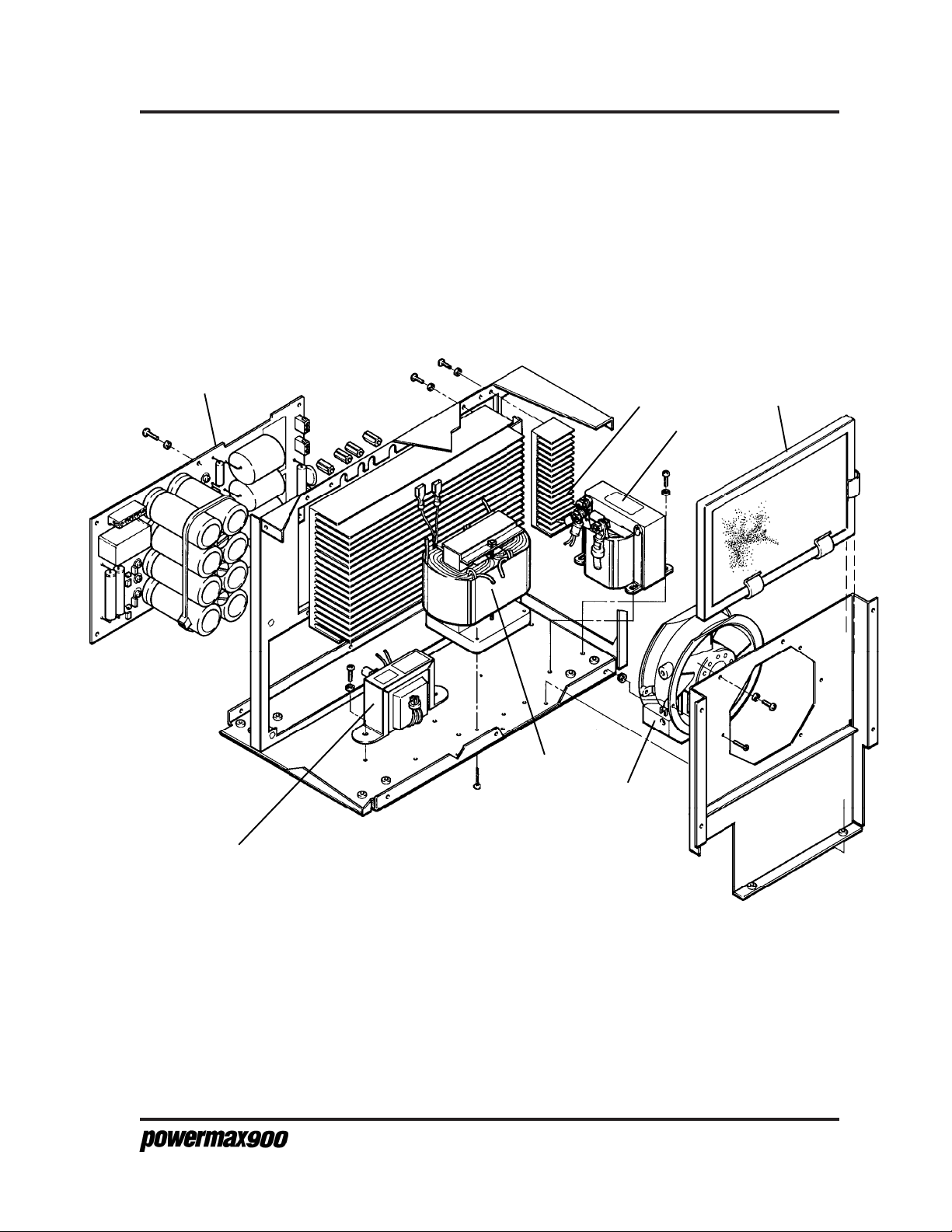
POWER SUPPLY - 208/240/480V
Bottom and Left Side
PARTS LIST - 208/240/480V
5
6
3
2
4
7
1
Figure 4-3 Powermax900 - 208/240/480V - Bottom and Left Side
Service Manual
4-7
Page 65

PARTS LIST - 208/240/480V
POWER SUPPLY - 208/240/480V
Rear
Index No. Part No. Description Ref. Desig. Quantity
1 001503 Pnl:Powermax800/900 Pwr Unit Plastic Rear 1
2 129068 Circuit Breaker SA:4Pole 480V W/TC S1 1
3 128405 Contactor Replacement:Powermax800/900 CR1 1
129300 Regulator SA:Powermax800/900 Pwr Unit 1
4 011072 Filter:20 Micron 1/8FPT 1
5 015285 Male Connector:1/8NPTX1/4Push in Tube 1
6 011079 Filter Element for 011072 Filter 1
129327 Linecord Panel SA:Powermax900 208/240/480V 1
7 001660* Panel:Powermax900 Power Cord 1
8 008228 Cord Grip:1NPT .690-.990 2Screws 1
9 129114 Power Cord SA:Powermax800/900 1
10 123099** Cable: Powermax800/900 Machine Interface
Notes: Bold part numbers and descriptions are subassemblies.
Indented normal type items are components of subassemblies
All mounting hardware in power supply drawings shown for reference only.
* Use 129332 to order power cord rear panel for 208/240/480V power supplies if you
have the machine interface option.
** Available only with the machine interface option.
See also Section 5 Parts List - 200/230/400V, and Section 6 Parts List - 400V CE
to identify parts for other Powermax900 power supplies.
4-8
5-99
Service Manual
Page 66

POWER SUPPLY - 208/240/480V
Rear
PARTS LIST - 208/240/480V
5
1
4
6
2
3
8
7
9
Figure 4-4 Powermax900 - 208/240/480V - Rear
Service Manual
10
4-9
5-99
Page 67

PARTS LIST - 208/240/480V
Powermax900 Field Upgrade Kits and Optional Parts
Part Number Description
028714 .................................. On/Off Pendant with Lead, 25 ft (7.6 m) (Also comes standard with most
machine torch system configurations. See note below.)
128061 .................................. On/Off Pendant with Lead, 50 ft (15.2 m)
128062 .................................. On/Off Pendant with Lead, 75 ft (23 m)
128316 .................................. Kit: Powermax900 Power Unit Wheels
128317 .................................. Kit: Powermax900 Pilot Arc Controller
128241 .................................. Kit: Powermax900 Machine Interface, 208/240/480V
028907 .................................. Work Cable, 50 ft (15.2 m)
028908 .................................. Kit: Powermax900, Cooling Air Filter
011079 .................................. Filter Element
129019 .................................. Jumper:Powermax900 Link Box
128312 .................................. Kit: Powermax900 600V Conversion
008809 .................................. Fuse:1A 600V 13/32 X 1-1/2 Slo
023206 .................................. Cable: Machine Interface, 25 ft (7.6 m) (Comes standard with machine torch
system configurations and with machine interface kits.)
024548 .................................. Leather Cable Covers, 25 ft (7.6 m)
POWER SUPPLIES - 208/240/480V, 1φ/3φ, 60 HZ
Part For With Pilot Arc With Machine
Number Torch Type Control Interface
083063 Hand No No
083076 Hand Yes No
083077 Machine No Yes
083078 Machine Yes Yes
Notes: Contact your distributor or call the nearest Hypertherm office for hand and machine
torch system configurations.
4-10
See also Section 5 Parts List - 200/230/400V, and Section 6 Parts List - 400V CE
to identify parts for other Powermax900 power supplies.
Service Manual
Page 68

PARTS LIST - 208/240/480V
RECOMMENDED SPARE PARTS - POWERMAX900- 208/240/480V
Part Number Description Page Reference
003078 ............................... Relay:30A NO Mag Blwt QDisc Term ........................................... 4-5
129068 ............................... Circuit Breaker SA:4Pole 480V W/TC .......................................... 4-9
128405 ............................... Contactor Replacement:Powermax800/900 ................................. 4-9
008809 ............................... Fuse:1A 600V 13/32X1-1/2Slo (2) ................................................ 4-4
014207 ............................... Xfmr:Powermax800/900 208-240-480 Control ............................. 4-7
014228 ............................... Xfmr:Powermax900 208-240-480 Power ...................................... 4-7
014230 ............................... Inductor:Powermax900 0.8MH 55A .............................................. 4-7
023922 ............................... Cable w/Clamp:PMX800/900 Work 20' ........................................ 4-3
027080 ............................... Fan:225CFM 120VAC 50-60HZ ................................................... 4-7
005112 ............................... Pressure Switch:39 Psi .013 Orifice ............................................. 4-3
006110 ............................... Sol. Valve:100# 1/8FPT 24VAC 3W ............................................. 4-3
011072 ............................... Filter:20 Micron 1/8FPT ................................................................ 4-9
011079 ............................... Filter Element for 011072 Filter .................................................... 4-9
011073 ............................... Regulator:0-125 Psig 1/8FPT ....................................................... 4-3
022027 ............................... Press. Gauge:160# 1.5" 1/8CBM Panel ....................................... 4-3
029957 ............................... Heatsink SA:Powermax800/900 Power Unit ................................ 4-5
109018/008906 .................. Diode:600V 100A UFast Recovery Dual (2)
/Thermal Pad:AL-380-100 (2) ....................................................... 4-5
109019/008904 .................. Diode:1600V 100A 3PH Module/Thermal Pad:AL-340-180 ......... 4-5
009849/008903 .................. Resistor:20-Ohm 50W 5% NON-IND (4)
/Thermal Pad: AL 197-114 (4) ...................................................... 4-5
009850/008902 .................. Resistor:20-Ohm 25W 5% NON-IND (4)
/Thermal Pad:AL 103-108 (4) ....................................................... 4-5
029998/008905 .................. IGBT Gate Drive SA:Powermax800/900 (2)
/Thermal Pad:AL-370-134 (2) ........................................................ 4-5
041668 ............................... PCB Assy:Powermax900 Micro Control ....................................... 4-5
041532 ............................... PCB Assy:Powermax800/900-ZB Power ...................................... 4-5, 4-7
129114 ............................... Cord/Plug:42 1Phase 8-3SO 3Prong 7'3" ..................................... 4-9
029674 ............................... MOV/Cap Assy:MAX42/43/70 3PH .............................................. 4-5
028908 ............................... Kit:Powermax800/900 Cooling Fan Filter ..................................... 4-7
Service Manual
4-11
9-99
Page 69

PARTS LIST - 208/240/480V
4-12
Service Manual
Page 70

PARTS LIST - 200/230/400V
Section 5 PARTS LIST - 200/230/400V
In this section:
Power Supply - 200/230/400V ............................................................ 5-2
Front ............................................................................................... 5-2
Top and Right Side ......................................................................... 5-4
Bottom and Left Side ...................................................................... 5-6
Rear ................................................................................................ 5-8
Powermax900 Field Upgrade Kits and Optional Parts ...................... 5-10
Power Supplies - 200/230/400V........................................................ 5-10
Recommended Spare Parts - Powermax900 - 200/230/400V .......... 5-11
Service Manual
5-1
Page 71

PARTS LIST - 200/230/400V
POWER SUPPLY - 200/230/400V
Front
Index No. Part No. Description Ref. Desig. Quantity
1 001502 Pnl:PMX800/900 Pwr Unit Plastic Front 1
2 004675 Spacer:PMX800/900 Pressure Gauge 1
3 008965 Knob:.850 Dia. 1/4 SFT Blk/Sil 1
4 023922 Cable w/Clamp:PMX800/900 Work 20' 1
129326 Manifold SA:PMX900 Pwr Unit 1
5 005112 Pressure Switch:39 Psi .013 Orifice PS1 1
6 006110 Sol. Valve:100# 1/8FPT 24VAC 3W V1 1
7 011073 Regulator:0-125 Psig 1/8FPT 1
8 022027 Press. Gauge:160# 1.5" 1/8CBM Panel 1
129356 Harness:PMX900 Power Unit 1
9 129325 Recept. SA:PMX900 Pwr Unit Quick Disc. 1
10 129389 Current Control Assy, PMX900 1
Notes: Bold part numbers and descriptions are subassemblies.
Indented normal type items are components of subassemblies
All mounting hardware in power supply drawings shown for reference only.
See also Section 4 Parts List - 208/240/480V, and Section 6 Parts List - 400V CE
to identify parts for other Powermax900 power supplies.
5-2
2-99
Service Manual
Page 72

POWER SUPPLY - 200/230/400V
Front
PARTS LIST - 200/230/400V
1
10
2
8
9
3
7
5
6
4
Figure 5-1 Powermax900 - 200/230/400V - Front
Service Manual
5-3
Page 73

PARTS LIST - 200/230/400V
POWER SUPPLY - 200/230/400V
Top and Right Side
Index No. Part No. Description Ref. Desig. Quantity
1 003078 Relay:30A NO Mag Blwt QDisc Term CR2 1
2 029674 MOV/Cap Assy:MAX42/43/70 3PH MOV1 1
029957 Heatsink SA:Powermax800/900 Power Unit 1
3 029998 IGBT Gate Drive SA:Powermax800/900 Q1 1
4 029998 IGBT Gate Drive SA:Powermax800/900 Q2 1
5 109018 Diode:600V 100A UFast Recovery Dual D2 1
6 109018 Diode:600V 100A UFast Recovery Dual D3 1
7 109019 Diode:1600V 100A 3PH Module D1 1
8 041668 PCB Assy:Pwrmx900 Micro Control 1
9 041532 PCB Assy:Powermax800/900-ZB Power 1
10 014137 Current Sense Transformer, 40A CS1 1
11 014137 Current Sense Transformer, 40A CS2 1
12 008958 Fuse:1A 500V 10mmX38mm Slo F1,F2 2
13 029978* Heatsink SA:Powermax800/900 PA Cont PCB Q3
14 041486* PCB Assy:Powermax800/900 PA Cont
128242** Kit:Powermax900 Machine Interface 200/230/400V
15 041494** PCB Assy:Powermax800/900 Machine Interface
Notes: Bold part numbers and descriptions are subassemblies.
Indented normal type items are components of subassemblies.
All mounting hardware in power supply drawings shown for reference only.
* Available only on power supplies with the pilot arc control option
** Available only on power supplies with the machine interface option
See also Section 4 Parts List - 208/240/480V, and Section 6 Parts List - 400V CE
to identify parts for other Powermax900 power supplies.
5-4
9-99
Service Manual
Page 74

POWER SUPPLY - 200/230/400V
Top and Right Side
15
PARTS LIST - 200/230/400V
13
14
8
3
10
11
2
4
7
12
5
6
1
9
Figure 5-2 Powermax900 - 200/230/400V - Top and Right Side
Service Manual
5-5
9-99
Page 75

PARTS LIST - 200/230/400V
POWER SUPPLY - 200/230/400V
Bottom and Left Side
Index No. Part No. Description Ref. Desig. Quantity
1 014208 Xfmr:Powermax800/900 200-230-400 Control T1 1
2 014229 Xfmr:Powermax900 200-230-400 Power T2 (w/TS2) 1
3 014230 Inductor:Powermax900 .08MH 55A L1 1
4 027443 Fan:260CDM 120VAC 50-60HZ M1 1
5 041532 PCB Assy:Powermax800/900-ZB Power 1
029978* Heatsink SA:Pwrmx800/900 PA Cont PCB Q3
6 004673* Heatsink:Powermax800/900 PA Cont
7 028908** Kit:Powermax800/900 Cooling Fan Filter
Notes: Bold part numbers and descriptions are subassemblies.
Indented normal type items are components of subassemblies
All mounting hardware in power supply drawings shown for reference only.
* Available only on power supplies with the pilot arc control option
** Available only as an option
See also Section 4 Parts List - 208/240/480V, and Section 6 Parts List - 400V CE
to identify parts for other Powermax900 power supplies.
5-6
Service Manual
Page 76

POWER SUPPLY - 200/230/400V
Bottom and Left Side
PARTS LIST - 200/230/400V
5
6
3
2
4
7
1
Figure 5-3 Powermax900 - 200/230/400V - Bottom and Left Side
Service Manual
5-7
Page 77

PARTS LIST - 200/230/400V
POWER SUPPLY - 200/230/400V
Rear
Index No. Part No. Description Ref. Desig. Quantity
1 001503 Pnl:Powermax800/900 Pwr Unit Plastic Rear 1
2 129068 Circuit Breaker SA:4Pole 480V W/TC S1 1
3 128405 Contactor Replacement:Powermax800/900 CR1 1
129300 Regulator SA:Powermax800/900 Pwr Unit 1
4 011072 Filter:20 Micron 1/8FPT 1
5 015285 Male Connector:1/8NPTX1/4Push in Tube 1
6 011079 Filter Element for 011072 Filter 1
129330 Linecord Panel SA:Powermax900 200/230/400V 1
7 001660* Panel:Powermax900 Power Cord 1
8 008228 Cord Grip:1NPT .690-.990 2Screws 1
9 129115 Power Cord SA:Powermax800/900 200V 1
10 123099** Cable: Powermax800/900 Machine Interface
Notes: Bold part numbers and descriptions are subassemblies.
Indented normal type items are components of subassemblies
All mounting hardware in power supply drawings shown for reference only.
* Use 129333 to order power cord rear panel for 200/230/400V power supplies if you
have the machine interface option.
** Available only with the machine interface option.
See also Section 4 Parts List - 208/240/480V, and Section 6 Parts List - 400V CE
to identify parts for other Powermax900 power supplies.
5-8
5-99
Service Manual
Page 78

POWER SUPPLY - 200/230/400V
Rear
PARTS LIST - 200/230/400V
5
1
4
6
2
3
8
7
9
Figure 5-4 Powermax900 - 200/230/400V - Rear
Service Manual
10
5-9
5-99
Page 79

PARTS LIST - 200/230/400V
Powermax900 Field Upgrade Kits and Optional Parts
Part Number Description
028714 .................................. On/Off Pendant with Lead, 25 ft (7.6 m) (Also comes standard with most
machine torch system configurations. See note below.)
128061 .................................. On/Off Pendant with Lead, 50 ft (15.2 m)
128062 .................................. On/Off Pendant with Lead, 75 ft (23 m)
128316 .................................. Kit: Powermax900 Power Unit Wheels
128317 .................................. Kit: Powermax900 Pilot Arc Controller
128242 .................................. Kit: Powermax900 Machine Interface, 200/230/400V
028907 .................................. Work Cable, 50 ft (15.2 m)
028908 .................................. Kit: Powermax900, Cooling Air Filter
011079 .................................. Filter Element
129019 .................................. Jumper:Powermax900 Link Box
008958 .................................. Fuse:1A 500V 10mm X 38mm Slo
023206 .................................. Cable: Machine Interface, 25 ft (7.6 m) (Comes standard with machine torch
system configurations and with machine interface kits.)
024548 .................................. Leather Cable Covers, 25 ft (7.6 m)
POWER SUPPLIES - 200/230/400V, 1φ/3φ, 50/60 HZ
Part For With Pilot Arc With Machine
Number Torch Type Control Interface
083065 Hand No No
083082 Hand Yes No
083083 Machine No Yes
083084 Machine Yes Yes
Notes: Contact your distributor or call the nearest Hypertherm office for hand and machine
torch system configurations.
See also Section 4 Parts List - 208/240/480V, and Section 6 Parts List - 400V CE
to identify parts for other Powermax900 power supplies.
5-10
Service Manual
Page 80

PARTS LIST - 200/230/400V
RECOMMENDED SPARE PARTS - POWERMAX900- 200/230/400V
Part Number Description Page Reference
003078 ............................... Relay:30A NO Mag Blwt QDisc Term ........................................... 5-5
129068 ............................... Circuit Breaker SA:4Pole 480V W/TC .......................................... 5-9
128405 ............................... Contactor Replacement:Powermax800/900 ................................. 5-9
008958 ............................... Fuse:1A 500V 10mmX38mm SLO (2) .......................................... 5-4
014208 ............................... Xfmr:Powermax800/900 200-230-400 Control ............................. 5-7
014229 ............................... Xfmr:Powermax900 200-230-400 Power ...................................... 5-7
014230 ............................... Inductor:Powermax900 0.8MH 55A .............................................. 5-7
023922 ............................... Cable w/Clamp:PMX800/900 Work 20' ........................................ 5-3
027443 ............................... Fan:260CDM 120VAC 50-60HZ ................................................... 5-7
005112 ............................... Pressure Switch:39 Psi .013 Orifice ............................................. 5-3
006110 ............................... Sol. Valve:100# 1/8FPT 24VAC 3W ............................................. 5-3
011072 ............................... Filter:20 Micron 1/8FPT ................................................................ 5-9
011079 ............................... Filter Element for 011072 Filter .................................................... 5-9
011073 ............................... Regulator:0-125 Psig 1/8FPT ....................................................... 5-3
022027 ............................... Press. Gauge:160# 1.5" 1/8CBM Panel ....................................... 5-3
029957 ............................... Heatsink SA:Powermax800/900 Power Unit ................................ 5-5
109018/008906 .................. Diode:600V 100A UFast Recovery Dual (2)
/Thermal Pad:AL-380-100 (2) ....................................................... 5-5
109019/008904 .................. Diode:1600V 100A 3PH Module/Thermal Pad:AL-340-180 ......... 5-5
009849/008903 .................. Resistor:20-Ohm 50W 5% NON-IND (4)
/Thermal Pad: AL 197-114 (4) ...................................................... 5-5
009850/008902 .................. Resistor:20-Ohm 25W 5% NON-IND (4)
/Thermal Pad:AL 103-108 (4) ....................................................... 5-5
029998/008905 .................. IGBT Gate Drive SA:Powermax800/900 (2)
/Thermal Pad:AL-370-134 (2) ....................................................... 5-5
041668 ............................... PCB Assy:Powermax900 Micro Control ....................................... 5-5
041532 ............................... PCB Assy:Powermax800/900-ZB Power ...................................... 5-5, 5-7
129115 ............................... Cord: 2.5mm PVC HD21/22 ......................................................... 5-9
029674 ............................... MOV/Cap Assy:MAX42/43/70 3PH .............................................. 5-5
028908 ............................... Kit:Powermax800/900 Cooling Fan Filter ..................................... 5-7
Service Manual
5-11
9-99
Page 81

PARTS LIST - 200/230/400V
5-12
Service Manual
Page 82

PARTS LIST - 400V CE
Section 6 PARTS LIST - 400V CE
In this section:
Power Supply - 400V CE .................................................................... 6-2
Front ............................................................................................... 6-2
Top and Right Side ......................................................................... 6-4
Bottom and Left Side ...................................................................... 6-6
Rear ................................................................................................ 6-8
Powermax900 Field Upgrade Kits and Optional Parts ...................... 6-10
Power Supplies - 400V CE................................................................ 6-10
Recommended Spare Parts - Powermax900 - 400V CE .................. 6-11
Service Manual
6-1
Page 83

PARTS LIST - 400V CE
POWER SUPPLY - 400V CE
Front
Index No. Part No. Description Ref. Desig. Quantity
1 001502 Pnl:PMX800/900 Pwr Unit Plastic Front 1
2 004675 Spacer:PMX800/900 Pressure Gauge 1
3 008965 Knob:.850 Dia. 1/4 SFT Blk/Sil 1
4 023922 Cable w/Clamp:PMX800/900 Work 20' 1
129326 Manifold SA:PMX900 Pwr Unit 1
5 005112 Pressure Switch:39 Psi .013 Orifice PS1 1
6 006110 Sol. Valve:100# 1/8FPT 24VAC 3W V1 1
7 011073 Regulator:0-125 Psig 1/8FPT 1
8 022027 Press. Gauge:160# 1.5" 1/8CBM Panel 1
129356 Harness:PMX900 Power Unit 1
9 129325 Recept. SA:PMX900 Pwr Unit Quick Disc. 1
10 129389 Current Control Assy, PMX900 1
Notes: Bold part numbers and descriptions are subassemblies.
Indented normal type items are components of subassemblies
All mounting hardware in power supply drawings shown for reference only.
See also Section 4 Parts List - 208/240/480V, and Section 5 Parts List -
200/230/400V to identify parts for other Powermax900 power supplies.
6-2
2-99
Service Manual
Page 84
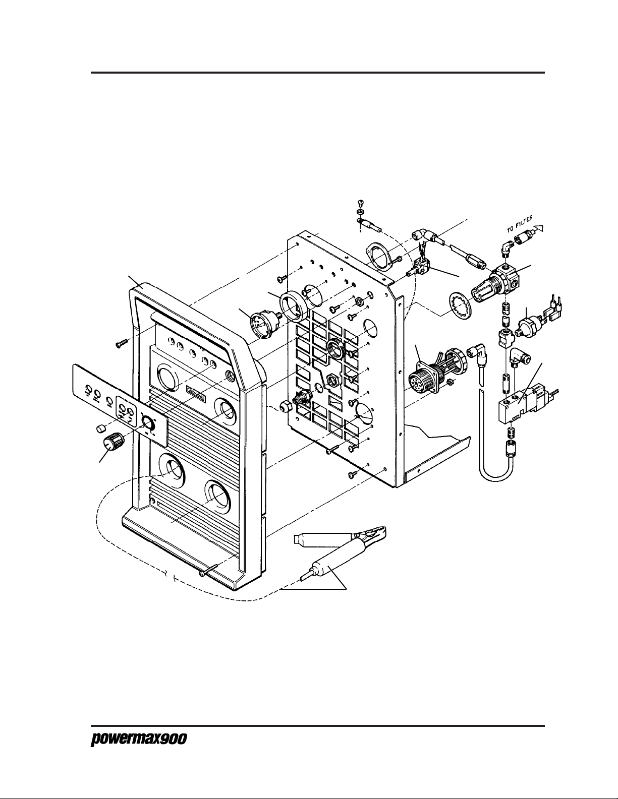
POWER SUPPLY - 400V CE
Front
PARTS LIST - 400V CE
1
10
2
8
17
9
3
7
5
6
4
Figure 6-1 Powermax900 - 400V CE - Front
Service Manual
6-3
Page 85

PARTS LIST - 400V CE
POWER SUPPLY - 400V CE
Top and Right Side
Index No. Part No. Description Ref. Desig. Quantity
1 003078 Relay:30A NO Mag Blwt QDisc Term CR2 1
129046 Heatsink SA:Powermax800/900 CE Power Unit 1
2 029998 IGBT Gate Drive SA:Powermax800/900 Q1 1
3 029998 IGBT Gate Drive SA:Powermax800/900 Q2 1
4 109018 Diode:600V 100A UFast Recovery Dual D2 1
5 109018 Diode:600V 100A UFast Recovery Dual D3 1
6 109043 Diode:1600V 30A 3PH Bridge Isol Bplr D1 1
7 041668 PCB Assy:Powermax900 Micro Control 1
8 041532 PCB Assy:Powermax800/900-ZB Power 1
9 014137 Current Sense Transformer, 40A CS1 1
10 014137 Current Sense Transformer, 40A CS2 1
11 008958 Fuse:1A 500V 10mmX38mm Slo F1, F2 2
12 008959 Fuse:20A 500V 10mmX38mm Slo 3
13 029978* Heatsink SA:Pwrmx800/900 PA Cont PCB Q3
14 041486* PCB Assy:Pwermax800/900 PA Cont
128286** Kit:Powermax900 Machine Interface 400V CE
15 041494** PCB Assy:Powermax800/900 Machine Interface
Notes: Bold part numbers and descriptions are subassemblies.
Indented normal type items are components of subassemblies.
All mounting hardware in power supply drawings shown for reference only.
* Available only on power supplies with the pilot arc control option
** Available only on power supplies with the machine interface option
See also Section 4 Parts List - 208/240/480V, and Section 5 Parts List -
200/230/400V to identify parts for other Powermax900 power supplies.
6-4
9-99
Service Manual
Page 86

POWER SUPPLY - 400V CE
Top and Right Side
15
PARTS LIST - 400V CE
13
14
7
2
12
3
11
6
4
5
10
9
1
8
Figure 6-2 Powermax900 - 400V CE - Top and Right Side
Service Manual
6-5
9-99
Page 87

PARTS LIST - 400V CE
POWER SUPPLY - 400V CE
Bottom and Left Side
Index No. Part No. Description Ref. Desig. Quantity
1 014209 Xfmr:Powermax800/900 CE 400V Control T1 1
2 014229 Xfmr:Powermax800/900 200-230-400 Power T2 (w/TS2) 1
3 014230 Inductor:Powermax900 0.8MH 55A L1 1
4 027443 Fan:260CDM 120VAC 50-60HZ M1 1
5 041532 PCB Assy:Powermax800/900-ZB Power 1
029978* Heatsink SA:Pwrmx800/900 PA Cont PCB Q3
6 004673* Heatsink:Powermax800/900 PA Cont
7 028908** Kit:Powermax800 Cooling Fan Filter
8 129100 Capacitor SA:Powermax800/900-CE 1
Notes: Bold part numbers and descriptions are subassemblies.
Indented normal type items are components of subassemblies.
All mounting hardware in power supply drawings shown for reference only.
* Available only on power supplies with the pilot arc control option
** Available only as an option
See also Section 4 Parts List - 208/240/480V, and Section 5 Parts List -
200/230/400V to identify parts for other Powermax900 power supplies.
6-6
Service Manual
Page 88

POWER SUPPLY - 400V CE
Bottom and Left Side
PARTS LIST - 400V CE
5
6
3
8
2
4
7
1
Figure 6-3 Powermax900 - 400V CE - Bottom and Left Side
Service Manual
6-7
Page 89

PARTS LIST - 400V CE
POWER SUPPLY - 400V CE
Rear
Index No. Part No. Description Ref. Desig. Quantity
1 001503 Pnl:Powermax800/900 Pwr Unit Plastic Rear 1
2 003132 Circuit Breaker SA:4Pole 480V W/TC S1 1
3 128405 Contactor Replacement:Powermax800/900 CR1 1
129300 Regulator SA:Powermax800/900 Pwr Unit 1
4 011072 Filter:20 Micron 1/8FPT 1
5 015285 Male Connector:1/8NPTX1/4Push in Tube 1
6 011079 Filter Element for 011072 Filter 1
129357 Linecord Panel SA:Powermax900 CE Pwr Unit 1
7 001571* Panel:Powermax800/900 Power Cord & EMI 1
8 008782 Strain Relief:3/4NPT .375-.500 1
109068*** Toroid:Powermax1100/900 1
9 129376 Power Cord SA:PMX900-CE/200-230- 1
10 041505 PCB Assy:Powermax800/900-CE Line Filter 1
11 123099** Cable: Powermax800 Machine Interface
Notes: Bold part numbers and descriptions are subassemblies.
Indented normal type items are components of subassemblies
All mounting hardware in power supply drawings shown for reference only.
* Use 129372 to replace power cord rear panel if you have the machine interface
option.
** Available only with the machine interface option
*** Not shown in Figure 6-4
See also Section 4 Parts List - 208/240/480V, and Section 5 Parts List -
200/230/400V to identify parts for other Powermax900 power supplies.
6-8
5-99
Service Manual
Page 90

POWER SUPPLY - 400V CE
Rear
PARTS LIST - 400V CE
5
1
4
6
2
3
10
11
9
7
8
Figure 6-4 Powermax900 - 400V CE - Rear
Service Manual
6-9
5-99
Page 91

PARTS LIST - 400V CE
Powermax900 Field Upgrade Kits and Optional Parts
Part Number Description
028714 .................................. On/Off Pendant with Lead, 25 ft (7.6 m) (Also comes standard with most
machine torch system configurations. See note below.)
128061 .................................. On/Off Pendant with Lead, 50 ft (15.2 m)
128062 .................................. On/Off Pendant with Lead, 75 ft (23 m)
128316 .................................. Kit: Powermax900 Power Unit Wheels
128317 .................................. Kit: Powermax900 Pilot Arc Controller
128286 .................................. Kit: Powermax900 Machine Interface, 400V CE
128313 .................................. Kit: Powermax900 CE 230V Conversion
028907 .................................. Work Cable, 50 ft (15.2 m)
028908 .................................. Kit: Powermax900, Cooling Air Filter
011079 .................................. Filter Element
129019 .................................. Jumper:Powermax900 Link Box
008958 .................................. Fuse:1A 500V 10mm X 38mm Slo
023206 .................................. Cable: Machine Interface, 25 ft (7.6 m) (Comes standard with machine
torch system configurations and with machine interface kits.)
024548 .................................. Leather Cable Covers, 25 ft (7.6 m)
109068 .................................. Toroid (Used only on 400V CE power supply linecord assemblies.)
POWER SUPPLIES - 400V CE, 3φ, 50 HZ
Part For With Pilot Arc With Machine
Number Torch Type Control Interface
083064 Hand No No
083079 Hand Yes No
083080 Machine No Yes
083081 Machine Yes Yes
Notes: Contact your distributor or call the nearest Hypertherm office for hand and machine torch
system configurations.
See also Section 4 Parts List - 208/240/480V, and Section 5 Parts List - 200/230/400V to
identify parts for other Powermax900 power supplies.
6-10
Service Manual
Page 92

PARTS LIST - 400V CE
RECOMMENDED SPARE PARTS - POWERMAX900 400V CE
Page
Part Number Description Reference
003078 ............................... Relay:30A NO Mag Blwt QDisc Term ................................................. 6-5
003132 ............................... Circuit Breaker SA:4Pole 480V W/TC ................................................ 6-9
128405 ............................... Contactor Replacement:Powermax800/900 ....................................... 6-9
008958 ............................... Fuse:1A 500V 10mm X 38mm GI Slo(2) ............................................ 6-5
008959 ............................... Fuse:20A 500V 10mm X 38mm GI Slo(3) .......................................... 6-5
014209 ............................... Xfmr:Powermax800/900 CE 400V Control ......................................... 6-7
014229 ............................... Xfmr:Powermax900 200/230/400 Power ............................................ 6-7
014230 ............................... Inductor:Powermax900 0.8MH 55A .................................................... 6-7
023922 ............................... Cable w/Clamp:PMX800/900 Work 20' .............................................. 6-3
027443 ............................... Fan:260CDM 120VAC 50-60HZ ......................................................... 6-7
005112 ............................... Pressure Switch:39 Psi .013 Orifice ................................................... 6-3
006110 ............................... Sol. Valve:100# 1/8FPT 24VAC 3W ................................................... 6-3
011072 ............................... Filter:20 Micron 1/8FPT ...................................................................... 6-9
011079 ............................... Filter Element for 011072 Filter .......................................................... 6-9
011073 ............................... Regulator:0-125 Psig 1/8FPT ............................................................. 6-3
022027 ............................... Press. Gauge:160# 1.5" 1/8CBM Panel ............................................. 6-3
129046 ............................... Heatsink SA:Powermax800/900 CE Power Unit ................................ 6-5
109018/008906 .................. Diode:600V 100A UFast Recovery Dual (2)
/Thermal Pad:AL-380-100 (2) ............................................................. 6-5
109043/008947 .................. Diode:1600V 30A 3PH Bridge/Thermal Pad:AL-315-114 ................... 6-5
009849/008903 .................. Resistor:20-Ohm 50W 5% NON-IND (4)
/Thermal Pad:AL-197-114 (4) ............................................................. 6-5
009850/008902 .................. Resistor:20-Ohm 25W 5% NON-IND (4)
/Thermal Pad:AL-103-108 (4) ............................................................. 6-5
029998/008905 .................. IGBT Gate Drive SA:Powermax800/.900 (2)
/Thermal Pad:AL-370-134 (2) ............................................................. 6-5
041668 ............................... PCB Assy:Powermax900 Micro Control ............................................. 6-5
041532 ............................... PCB Assy:Powermax800/900-ZB Power ..................................... 6-5, 6-7
129049 ............................... Electric Line Filter SA:Powermax800/900-CE .................................... 6-9
129376 ............................... Power Cord SA:Powermax900-CE ..................................................... 6-9
028908 ............................... Kit:Powermax800/900 Cooling Fan Filter ........................................... 5-7
Service Manual
6-11
9-99
Page 93

PARTS LIST - 400V CE
6-12
Service Manual
Page 94

PARTS LIST - TORCH AND CONSUMABLES
Section 7 PARTS LIST -
TORCHES AND CONSUMABLES
In this section:
PAC125T Torch Assembly................................................................... 7-2
PAC125M Torch Assembly .................................................................. 7-3
Consumable Parts Kits........................................................................ 7-4
Consumable Configurations ................................................................ 7-5
Service Manual
7-1
Page 95

PARTS LIST - TORCH AND CONSUMABLES
PAC125T Torch Assembly and 25 ft (7.6 m) Lead - 083066
PAC125T Torch Assembly and 50 ft (15.2 m) Lead - 083067
Part Number Description
001288 ...................................... Handle, PAC121/125T
002244 ...................................... Safety Trigger, PAC121/125T
128284 ...................................... Kit: Switch Repair
120573 ...................................... Electrode, Air
120576 ...................................... Ring, Swirl
027254 ...................................... Trigger Spring, PAC121/125T
004764 ...................................... Ring, Gutcha
075339 ...................................... Screws, P/S, # 4 X 1/2, PH, RND, S/B
120577 ...................................... Nozzle: PAC125 55A Shield
120601 ...................................... Shield: PAC121T
120600 ...................................... Cap, Retaining
120570 ...................................... Torch Main Body with Switch, PAC125T
044016 ............................................ O-Ring: BUNA 90 Duro .614X.070
129352 ...................................... Torch Lead, 25 ft (7.6 m)
129353 ...................................... Torch Lead, 50 ft (15.2 m)
044009 ............................................ Quick Disconnect O-Ring (not shown)
* Used only in 083066
** Used only in 083067
Note: See page 7-4 or 7-5 for detail of consumable parts
Torch
Handle
001288
Trigger
Spring
027254
Safety
Trigger
002244
Torch Main
Body w/ Switch
120570
O-Ring
Figure 4-5 PAC121TS Torch Assembly and Leads
044016
Pushbutton
Switch
128284
Gutcha
Ring
004764
Torch Lead
129352, 25 ft (7.63 m)
129353, 50 ft (15.25 m)
Handle
001288
Screw (5)
075339
7-2
Figure 7-1 PAC125T Torch Assembly and Leads
Service Manual
Page 96

PARTS LIST - TORCH AND CONSUMABLES
PAC125M Torch Assembly and 14 ft (4.3 m) Lead - 083069 w/pigtail, 083073 no pigtail
PAC125M Torch Assembly and 25 ft (7.6 m) Lead - 083068 w/pigtail, 083072 no pigtail
PAC125M Torch Assembly and 35 ft (10.6 m) Lead - 083070 w/pigtail, 083074 no pigtail
PAC125M Torch Assembly and 50 ft (15.2 m) Lead - 083071 w/pigtail, 083075 no pigtail
Part Number Description
120573 ............................................ Electrode, Air
120576 ............................................ Ring, Swirl
120613 ............................................ Sleeve, Machine Torch, PAC125M
020620 ............................................ Sleeve, Torch Position, PAC121/125M
129339 ............................................ Torch Lead w/pigtail, 14 ft (4.3 m)
129338 ............................................ Torch Lead w/pigtail, 25 ft (7.6 m)
129340 ............................................ Torch Lead w/pigtail, 35 ft (10.6 m)
129341 ............................................ Torch Lead w/pigtail, 50 ft (15.2 m)
129343 ............................................ Torch Lead, no pigtail, 14 ft (4.3 m)
129342 ............................................ Torch Lead, no pigtail, 25 ft (7.6 m)
129344 ............................................ Torch Lead, no pigtail, 35 ft (10.6 m)
129345 ............................................ Torch Lead, no pigtail, 50 ft (15.2 m)
044009 ................................................... Quick Disconnect O-Ring (not shown)
027599 ............................................ Snap Ring
120577 ............................................ Nozzle: PAC125 55A Shield
120602 ............................................ Shield: PAC121M Machine Torch
120600 ............................................ Cap, Retaining
120583 ............................................ Torch Main Body w/ Switch, PAC125M
044016 ................................................... O-Ring: BUNA 90 Duro .614X.070
Note: See page 7-4 for detail of consumable parts
Torch Main
Body
120583
Snap Ring
027599
Torch Sleeve
120613
On/Off Pendant (not part of machine torch assembly See
Powermax900 Field Upgrade Kits and Optional Parts
Sections 4, 5 or 6 for part numbers)
O-Ring
044016
O-Ring
044016
Torch Position
Sleeve
020620
in
Torch Lead
129339, with pigtail, 14 ft (4.3 m)
129338, with pigtail, 25 ft (7.6 m)
129340, with pigtail, 35 ft (10.6 m)
129341, with pigtail, 50 ft (15.2 m)
129343, no pigtail, 14 ft (4.3 m)
129342, no pigtail, 25 ft (7.6 m)
129344, no pigtail, 35 ft (10.6 m)
129345, no pigtail, 50 ft (15.2 m)
Pigtail
Figure 7-2 PAC125M Torch Assembly and Leads
Service Manual
7-3
Page 97

PARTS LIST - TORCH AND CONSUMABLES
Consumable Parts Kits
Hand Consumable Spare Parts Kit (128287)
Part Number Description (Quantity)
001285 ...................Box, Consumable Parts (1)
120573 ...................Electrode (3)
120574 ...................Electrode, Extended (1)
120577 ...................Nozzle, 55A, Shielded (3)
120578 ...................Nozzle, Pipe Saddle, Extended (1)
120607 ...................Nozzle, Gouging (1)
120601 ...................Shield, 55A (1)
120608 ...................Shield, Gouging (1)
120303 ...................Deflector (1)
044016 ...................O-Ring (3)
015152 ...................Nipple, 1/8 NPT,QDisc, Steel (1)
015604 ...................Reducer, 1/4 FPT X 1/8 NPT, Brass (1)
027055 ...................Lubricant, Silicone 1/4 Oz Tube (1)
Machine Consumable Spare Parts Kit (128288)
Part Number Description (Quantity)
001285 ...................Box, Consumable Parts (1)
120573 ...................Electrode (3)
120574 ...................Electrode, Extended (3)
120577 ...................Nozzle, 55A, Shielded (3)
120606 ...................Nozzle, 35A, Extended (3)
120602 ...................Shield, PAC125M Machine Torch (1)
120303 ...................Deflector (1)
044016 ...................O-Ring (3)
015152 ...................Nipple, 1/8 NPT, QDisc, Steel (1)
015604 ...................Reducer, 1/4 FPT X 1/8 NPT, Brass (1)
027055 ...................Lubricant, Silicone 1/4 Oz Tube (1)
7-4
Consumable Spare Parts Kit - CE (128289)
Part Number Description (Quantity)
001285 ...................Box, Consumable Parts (1)
120573 ...................Electrode, Air (3)
120577 ...................Nozzle, 55A, Shielded (3)
120607 ...................Nozzle, Gouging (1)
120608 ...................Shield, Gouging (1)
120601 ...................Shield, 55A (1)
044016 ...................O-Ring (3)
015152 ...................Nipple, 1/8 NPT, QDisc, Steel (1)
015301 ...................Adapter, 1/8 NPT to 1/4 Hose (1)
027055 ...................Lubricant, Silicone 1/4 Oz Tube (1)
Service Manual
Page 98

Consumable Configurations
PARTS LIST - TORCH AND CONSUMABLES
Shielded
Hand Torch
55A Cutting
Shielded
Machine Torch
55A Cutting
Shielded
55A Gouging
Shield
120601
Shield
120602
Shield
120608
Retaining Cap
120600
Retaining Cap
120600
Retaining Cap
120600
Nozzle
120577
Nozzle
120577
Nozzle
120607
Electrode
120573
Electrode
120573
Electrode
120573
Swirl Ring
120576
Swirl Ring
120576
Swirl Ring
120576
PAC125
Torch
PAC125
Torch
PAC125
Torch
Figure 7-3 Shielded Consumable Configurations
Deflector
120303
Retaining Cap
120600
Nozzle
120578 (55A)
Electrode
120574
Unshielded
55A Cutting*
Deflector
120303
Retaining Cap
120600
Nozzle
120606 (35A)
Electrode
120574
Unshielded
35A Cutting*
Figure 7-4 Unshielded Consumable Configurations
* In CE countries, use unshielded consumables only in machine-torch applications.
Swirl Ring
120576
Swirl Ring
120576
PAC125
Torch
PAC125
Torch
Service Manual
7-5
Page 99

PARTS LIST - TORCH AND CONSUMABLES
7-6
Service Manual
Page 100

WIRING DIAGRAMS
Section 8 WIRING DIAGRAMS
In this section:
Powermax900 Electrical Schematic: 208/240/480V .......................... 8-2
Powermax900 Electrical Schematic: 200/230/400V .......................... 8-3
Powermax900 Electrical Schematic: 400V–CE ................................. 8-4
Service Manual
8-1
 Loading...