

Page 1

Plasma arc cutting systems
85
Service Manual – 807120
Revision 0
Page 2

Register your new Hypertherm system
Register your product on-line at www.hypertherm.com/registration for
easier technical and warranty support. You can also receive updates on
new Hypertherm products and a free gift as a token of our appreciation.
For your records
Serial number: _____________________________________________
Purchase date: _____________________________________________
Distributor: _____________________________________________
________________________________________________________
________________________________________________________
Maintenance notes:
____________________________________________________________
____________________________________________________________
____________________________________________________________
____________________________________________________________
____________________________________________________________
____________________________________________________________
Page 3

powermax
65
powermax
Service Manual
(P/N 807120)
85
Hypertherm and Powermax are trademarks of Hypertherm, Inc.
and may be registered in the United States and/or other countries.
Revision 0 – February 2011
Hypertherm, Inc.
Hanover, NH USA
www.hypertherm.com
email: info@hypertherm.com
© Copyright 2011 Hypertherm, Inc.
All Rights Reserved
Page 4

Hypertherm, Inc.
Etna Road, P.O. Box 5010
Hanover, NH 03755 USA
603-643-3441 Tel (Main Office)
603-643-5352 Fax (All Departments)
info@hypertherm.com (Main Office Email)
800-643-9878 Tel (Technical Service)
technical.service@hypertherm.com (Technical Service Email)
800-737-2978 Tel (Customer Service)
customer.service@hypertherm.com (Customer Service Email)
Hypertherm Automation
5 Technology Drive, Suite 300
West Lebanon, NH 03784 USA
603-298-7970 Tel
603-298-7977 Fax
Hypertherm Europe B.V.
Vaartveld 9
4704 SE
Roosendaal, Nederland
31 165 596907 Tel
31 165 596901 Fax
31 165 596908 Tel (Marketing)
31 165 596900 Tel (Technical Service)
00 800 4973 7843 Tel (Technical Service)
Hypertherm Japan Ltd.
Level 9, Edobori Center Building
2-1-1 Edobori, Nishi-ku
Osaka 550-0002 Japan
81 6 6225 1183 Tel
81 6 6225 1184 Fax
Hypertherm Plasmatechnik GmbH
Technologiepark Hanau
Rodenbacher Chaussee 6
D-63457 Hanau-Wolfgang, Deutschland
49 6181 58 2100 Tel
49 6181 58 2134 Fax
49 6181 58 2123 (Technical Service)
Hypertherm (S) Pte Ltd.
82 Genting Lane
Media Centre
Annexe Block #A01-01
Singapore 349567, Republic of Singapore
65 6841 2489 Tel
65 6841 2490 Fax
65 6841 2489 (Technical Service)
Hypertherm (Shanghai) Trading Co., Ltd.
Unit A, 5th Floor, Careri Building
432 West Huai Hai Road
Shanghai, 200052
PR China
86-21 5258 3330/1 Tel
86-21 5258 3332 Fax
Hypertherm Brasil Ltda.
Avenida Doutor Renato de
Andrade Maia 350
Parque Renato Maia
CEP 07114-000
Guarulhos, SP Brasil
55 11 2409 2636 Tel
55 11 2408 0462 Fax
Hypertherm México, S.A. de C.V.
Avenida Toluca No. 444, Anexo 1,
Colonia Olivar de los Padres
Delegación Álvaro Obregón
México, D.F. C.P. 01780
52 55 5681 8109 Tel
52 55 5683 2127 Fax
12/17/09
Page 5

ELECTROMAGNETIC COMPATIBILITY EMC
Introduction
Hypertherm’s CE-marked equipment is built in
compliance with standard EN60974-10. The equipment
should be installed and used in accordance with
the information below to achieve electromagnetic
compatibility.
The limits required by EN60974-10 may not be
adequate to completely eliminate interference when the
affected equipment is in close proximity or has a high
degree of sensitivity. In such cases it may be necessary
to use other measures to further reduce interference.
This cutting equipment is designed for use only in an
industrial environment.
Installation and use
The user is responsible for installing and using the
plasma equipment according to the manufacturer’s
instructions.
If electromagnetic disturbances are detected then it shall
be the responsibility of the user to resolve the situation
with the technical assistance of the manufacturer. In
some cases this remedial action may be as simple
as earthing the cutting circuit, see Earthing of the
workpiece. In other cases, it could involve constructing
an electromagnetic screen enclosing the power source
and the work complete with associated input filters. In all
cases, electromagnetic disturbances must be reduced to
the point where they are no longer troublesome.
Assessment of area
Before installing the equipment, the user shall make an
assessment of potential electromagnetic problems in
the surrounding area. The following shall be taken into
account:
a. Other supply cables, control cables, signaling and
telephone cables; above, below and adjacent to the
cutting equipment.
b. Radio and television transmitters and receivers.
c. Computer and other control equipment.
d. Safety critical equipment, for example guarding of
industrial equipment.
e. Health of the people around, for example the use of
pacemakers and hearing aids.
f. Equipment used for calibration or measurement.
g. Immunity of other equipment in the environment. User
shall ensure that other equipment being used in the
environment is compatible. This may require additional
protection measures.
h. Time of day that cutting or other activities are to be
carried out.
The size of the surrounding area to be considered
will depend on the structure of the building and other
activities that are taking place. The surrounding area
may extend beyond the boundaries of the premises.
Methods of reducing emissions
Mains supply
Cutting equipment must be connected to the
mains supply according to the manufacturer’s
recommendations. If interference occurs, it may be
necessary to take additional precautions such as filtering
of the mains supply.
Compliance Information EMC-1
7/10
Page 6

ELECTROMAGNETIC COMPATIBILITY
Consideration should be given to shielding the supply
cable of permanently installed cutting equipment,
in metallic conduit or equivalent. Shielding should
be electrically continuous throughout its length. The
shielding should be connected to the cutting mains
supply so that good electrical contact is maintained
between the conduit and the cutting power source
enclosure.
Maintenance of cutting equipment
The cutting equipment must be routinely maintained
according to the manufacturer’s recommendations. All
access and service doors and covers should be closed
and properly fastened when the cutting equipment is in
operation. The cutting equipment should not be modified
in any way, except as set forth in and in accordance with
the manufacturer’s written instructions. For example,
the spark gaps of arc striking and stabilizing devices
should be adjusted and maintained according to the
manufacturer’s recommendations.
Cutting cables
The cutting cables should be kept as short as possible
and should be positioned close together, running at or
close to the floor level.
Earthing of the workpiece
Where the workpiece is not bonded to earth for
electrical safety, nor connected to earth because of its
size and position, for example, ship’s hull or building
steel work, a connection bonding the workpiece to earth
may reduce emissions in some, but not all instances.
Care should be taken to prevent the earthing of the
workpiece increasing the risk of injury to users, or
damage to other electrical equipment. Where necessary,
the connection of the workpiece to earth should be
made by a direct connection to the workpiece, but
in some countries where direct connection is not
permitted, the bonding should be achieved by suitable
capacitances selected according to national regulations.
Note: The cutting circuit may or may not be earthed for
safety reasons. Changing the earthing arrangements
should only be authorized by a person who is competent
to assess whether the changes will in crease the risk of
injury, for example, by allowing parallel cutting current
return paths which may damage the earth circuits of
other equipment. Further guidance is provided in
IEC 60974-9, Arc Welding Equip ment, Part 9:
Installation and Use.
Screening and shielding
Equipotential bonding
Bonding of all metallic components in the cutting
installation and adjacent to it should be considered.
However, metallic components bonded to the workpiece
will increase the risk that the operator could receive a
shock by touching these metallic components and the
electrode (nozzle for laser heads) at the same time.
The operator should be insulated from all such bonded
metallic components.
Selective screening and shielding of other cables
and equipment in the surrounding area may alleviate
problems of interference. Screening of the entire plasma
cutting installation may be considered for special
applications.
EMC-2 Compliance Information
7/10
Page 7

WARRANTY
Attention
Genuine Hypertherm parts are the factoryrecommended replacement parts for your Hypertherm
system. Any damage or injury caused by the use of other
than genuine Hypertherm parts may not be covered by
the Hypertherm warranty, and will constitute misuse of
the Hypertherm Product.
You are solely responsible for the safe use of the
Product. Hypertherm does not and cannot make any
guarantee or warranty regarding the safe use of the
product in your environment.
General
Hypertherm, Inc. warrants that its Products shall be
free from defects in materials and workmanship for the
specific periods of time set forth herein and as follows:
if Hypertherm is notified of a defect (i) with respect to
the power supply within a period of two (2) years from
the date of its delivery to you, with the exception of
Powermax brand power supplies, which shall be within
a period of three (3) years from the date of delivery to
you, and (ii) with respect to the torch and leads within
a period of one (1) year from its date of delivery to you,
and with respect to torch lifter assemblies within a
period of one (1) year from its date of delivery to you,
and with respect to laser heads within a period of one
(1) year from its date of delivery to you, and with respect
to Automation products one (1) year from its date of
delivery to you, with the exception of the EDGE Pro
CNC and ArcGlide THC, which shall be within a period
of two (2) years from the date of delivery to you.
Hypertherm provides repair, replacement or adjustment
of the Product as the sole and exclusive remedy, if
and only if the warranty set forth herein properly is
invoked and applies. Hypertherm, at its sole option,
shall repair, replace, or adjust, free of charge, any
defective Products covered by this warranty which
shall be returned with Hypertherm’s prior authorization
(which shall not be unreasonably withheld), properly
packed, to Hypertherm’s place of business in Hanover,
New Hampshire, or to an authorized Hypertherm repair
facility, all costs, insurance and freight pre paid by the
customer. Hypertherm shall not be liable for any repairs,
replacement, or adjustments of Products covered by this
warranty, except those made pursuant to this paragraph
and with Hypertherm’s prior written consent.
The warranty set forth above is exclusive and is in
lieu of all other warranties, express, implied, statutory,
or otherwise with respect to the Products or as to
the results which may be obtained therefrom, and
all implied warranties or conditions of quality or of
merchantability or fitness for a particular purpose or
against infringement. The foregoing shall constitute the
sole and exclusive remedy for any breach by Hypertherm
of its warranty.
Distributors/OEMs may offer different or additional
warranties, but Distributors/OEMs are not authorized to
give any additional warranty protection to you or make
any representation to you purporting to be binding upon
Hypertherm.
This warranty shall not apply to any Powermax brand
power supplies that have been used with phase
converters. In addition, Hypertherm does not warranty
systems that have been damaged as a result of poor
power quality, whether from phase converters or
incoming line power. This warranty shall not apply to any
Product which has been incorrectly installed, modified,
or otherwise damaged.
Compliance Information W-1
9/10
Page 8

WARRANTY
Patent indemnity
Except only in cases of products not manufactured by
Hypertherm or manufactured by a person other than
Hypertherm not in strict conformity with Hypertherm’s
specifications and in cases of designs, processes,
formulae, or combinations not developed or purported
to be developed by Hypertherm, Hypertherm will have
the right to defend or settle, at its own expense, any
suit or proceeding brought against you alleging that
the use of the Hypertherm product, alone and not in
combination with any other product not supplied by
Hypertherm, infringes any patent of any third party. You
shall notify Hypertherm promptly upon learning of any
action or threatened action in connection with any such
alleged infringement (and in any event no longer than
fourteen (14) days after learning of any action or threat
of action), and Hypertherm’s obligation to defend shall
be conditioned upon Hypertherm’s sole control of, and
the indemnified party’s cooperation and assistance in,
the defense of the claim.
Limitation of liability
In no event shall Hypertherm be liable to any
person or entity for any incidental, consequential
direct, indirect, punitive or exemplary damages
(including but not limited to lost profits)
regardless of whether such liability is based on
breach of contract, tort, strict liability, breach
of warranty, failure of essential purpose, or
otherwise, and even if advised of the possibility
of such damages.
Insurance
At all times you will have and maintain insurance in such
quantities and types, and with coverage sufficient and
appropriate to defend and to hold Hypertherm harmless
in the event of any cause of action arising from the use
of the products.
Transfer of rights
You may transfer any remaining rights you may have
hereunder only in connection with the sale of all or
substantially all of your assets or capital stock to a
successor in interest who agrees to be bound by all of
the terms and conditions of this Warranty. Within thirty
(30) days before any such transfer occurs, you agree to
notify in writing Hypertherm, which reserves the right of
approval. Should you fail timely to notify Hypertherm and
seek its approval as set forth herein, the Warranty set
forth herein shall be null and void and you will have no
further recourse against Hypertherm under the Warranty
or otherwise.
National and local codes
National and local codes governing plumbing and
electrical installation shall take precedence over any
instructions contained in this manual. In no event shall
Hypertherm be liable for injury to persons or property
damage by reason of any code violation or poor work
practices.
Liability cap
In no event shall Hypertherm’s liability, if any,
whether such liability is based on breach of
contract, tort, strict liability, breach of warranties,
failure of essential purpose or otherwise, for
any claim, action, suit or proceeding (whether
in court, arbitration, regulatory proceeding or
otherwise) arising out of or relating to the use of
the Products exceed in the aggregate the amount
paid for the Products that gave rise to such claim.
W-2 Compliance Information
9/10
Page 9

TABLE OF CONTENTS
Safety information
Before operating any Hypertherm equipment, read the separate Safety and Compliance Manual (80669C) included
with your product for important safety information.
powermax
65/85
Service Manual
v
Page 10

TABLE OF CONTENTS
vi powermax
65/85
Service Manual
Page 11

TABLE OF CONTENTS
Section 1
Specifications
Safety information ...................................................................................................................................................................................1-2
System description .................................................................................................................................................................................1-2
Where to find information .....................................................................................................................................................................1-3
Power supply dimensions ..................................................................................................................................................................... 1-4
Component weights ...............................................................................................................................................................................1-5
Powermax65 power supply ratings ....................................................................................................................................................1-6
Powermax85 power supply ratings ....................................................................................................................................................1-8
H65/H85 75° hand torch dimensions ............................................................................................................................................ 1-10
H65s/H85s 15° hand torch dimensions ........................................................................................................................................ 1-10
M65/M85 full-length machine torch dimensions .......................................................................................................................... 1-11
M65m/M85m mini-machine torch dimensions ............................................................................................................................. 1-11
Powermax65 cutting specifications ................................................................................................................................................. 1-12
Powermax85 cutting specifications ................................................................................................................................................. 1-13
Symbols and markings ........................................................................................................................................................................ 1-14
IEC symbols .......................................................................................................................................................................................... 1-15
Section 2
Power Supply Setup
Unpack the Powermax65 or Powermax85 system .........................................................................................................................2-2
Claims .............................................................................................................................................................................................2-2
Contents .........................................................................................................................................................................................2-3
Position the power supply.....................................................................................................................................................................2-4
Prepare the electrical power ................................................................................................................................................................2-4
Install a line-disconnect switch .................................................................................................................................................2-5
Requirements for grounding ......................................................................................................................................................2-5
Power connection for the Powermax65 ............................................................................................................................................2-6
Single-phase power cord (not for CE model) ..................................................................................................................................2-7
Three-phase power cord — plug installation....................................................................................................................................2-7
Power connection for the Powermax85 ............................................................................................................................................2-8
Single-phase power cord (not for CE model) ..................................................................................................................................2-9
Single-phase power cord installation ................................................................................................................................... 2-10
Three-phase power cord — plug installation................................................................................................................................. 2-11
Extension cord recommendations .................................................................................................................................................... 2-11
Extension cord specifications ................................................................................................................................................. 2-12
Engine-driven generator recommendations ........................................................................................................................ 2-13
Prepare the gas supply ....................................................................................................................................................................... 2-14
Additional gas filtration ............................................................................................................................................................. 2-14
Connect the gas supply ........................................................................................................................................................... 2-15
powermax
65/85
Service Manual
vii
Page 12

TABLE OF CONTENTS
Section 3
Torch Setup
Introduction ..............................................................................................................................................................................................3-2
Consumable life .......................................................................................................................................................................................3-2
Hand torch setup .................................................................................................................................................................................... 3-3
Choose the hand torch consumables .....................................................................................................................................3-4
Hand torch consumables ...........................................................................................................................................................3-5
Install the hand torch consumables ..........................................................................................................................................3-6
Machine torch setup...............................................................................................................................................................................3-7
Converting an M65/M85 torch to an M65m/M85m torch .................................................................................................3-8
Mount the torch .......................................................................................................................................................................... 3-10
Choose the machine torch consumables ............................................................................................................................ 3-12
Machine torch consumables ................................................................................................................................................... 3-12
Install the machine torch consumables ................................................................................................................................ 3-15
Aligning the torch ...................................................................................................................................................................... 3-15
Connecting an optional remote-start pendant ...................................................................................................................3-16
Connecting an optional machine interface cable ............................................................................................................... 3-17
Connecting the torch lead ................................................................................................................................................................. 3-22
Using the cut charts ............................................................................................................................................................................ 3-23
Estimated kerf-width compensation ...................................................................................................................................... 3-24
85 A shielded consumables ................................................................................................................................................... 3-26
65 A shielded consumables ................................................................................................................................................... 3-30
45 A shielded consumables ................................................................................................................................................... 3-34
FineCut® consumables ............................................................................................................................................................ 3-38
85 A unshielded consumables ............................................................................................................................................... 3-41
65 A unshielded consumables ............................................................................................................................................... 3-45
45 A unshielded consumables ............................................................................................................................................... 3-49
Section 4
Operation
Controls and indicators .........................................................................................................................................................................4-2
Rear controls .................................................................................................................................................................................4-2
Front controls and LEDs .............................................................................................................................................................4-2
Status screen ................................................................................................................................................................................4-4
Operating the Powermax65 or Powermax85 ...................................................................................................................................4-6
Connect the electrical power, gas supply, and torch lead .................................................................................................4-6
Attach the work lead to the power supply ..............................................................................................................................4-7
Attach the work clamp to the workpiece ................................................................................................................................4-8
Turn ON the system .....................................................................................................................................................................4-9
Set the operating mode switch .................................................................................................................................................4-9
Check the indicators ................................................................................................................................................................. 4-10
Manually adjusting the gas pressure ..................................................................................................................................... 4-10
Adjusting the current (amperage) .......................................................................................................................................... 4-11
Understanding duty-cycle limitations .................................................................................................................................... 4-12
viii powermax
65/85
Service Manual
Page 13

TABLE OF CONTENTS
Using the hand torch ........................................................................................................................................................................... 4-13
Operate the safety trigger ....................................................................................................................................................... 4-13
Hand torch cutting hints .......................................................................................................................................................... 4-14
Start a cut from the edge of the workpiece......................................................................................................................... 4-15
Pierce a workpiece .................................................................................................................................................................... 4-16
Gouge a workpiece ..................................................................................................................................................................4-17
Common hand-cutting faults .................................................................................................................................................. 4-20
Using the machine torch .................................................................................................................................................................... 4-21
Ensure the torch and table are set up correctly ................................................................................................................. 4-21
Understand and optimize cut quality ..................................................................................................................................... 4-21
To pierce a workpiece using the machine torch ................................................................................................................ 4-23
Common machine-cutting faults ............................................................................................................................................ 4-24
Section 5
Troubleshooting and System Tests
Controls and indicators .........................................................................................................................................................................5-3
Theory of operation .................................................................................................................................................................................5-4
General ...........................................................................................................................................................................................5-4
200-600 V CSA 1- or 3-phase power supply functional description ............................................................................. 5-4
380/400 V CE 3-phase power supply functional description ...........................................................................................5-5
Sequence of operation ................................................................................................................................................................5-6
Troubleshooting preparation ................................................................................................................................................................5-7
Test equipment .............................................................................................................................................................................5-7
Troubleshooting procedures and sequence ..........................................................................................................................5-7
External inspection ....................................................................................................................................................................... 5-9
Internal inspection ........................................................................................................................................................................5-9
Initial resistance check ...........................................................................................................................................................................5-9
Check the power switch .............................................................................................................................................................5-9
Hypertherm IGBT tester ..........................................................................................................................................................5-12
Indicator LEDs and device tests ............................................................................................................................................ 5-12
IGBT test preparation ............................................................................................................................................................... 5-13
IGBT device test using the Hypertherm tester ................................................................................................................... 5-14
Troubleshoot the Hypertherm IGBT tester .......................................................................................................................... 5-14
Schematic for building an IGBT tester ................................................................................................................................. 5-15
IGBT device test using a non-Hypertherm tester .............................................................................................................. 5-16
200-600V CSA power supply overview ........................................................................................................................................ 5-17
380/400V CE power supply overview............................................................................................................................................ 5-18
200-600V CSA power supply overview (power board removed) ...........................................................................................5-19
380/400V CE power supply overview (power board removed) ............................................................................................... 5-20
powermax
65/85
Service Manual
ix
Page 14

TABLE OF CONTENTS
Fault codes ............................................................................................................................................................................................ 5-21
Displaying the service screen ................................................................................................................................................. 5-21
Important fault icons ................................................................................................................................................................. 5-22
Performing a cold restart ......................................................................................................................................................... 5-22
Fault codes and solutions ........................................................................................................................................................ 5-23
Troubleshooting guide ........................................................................................................................................................................ 5-32
System tests.......................................................................................................................................................................................... 5-38
Test 1 – Voltage input .............................................................................................................................................................. 5-39
Test 2 – DC Power Buss ........................................................................................................................................................ 5-40
Test 3 – Output diodes............................................................................................................................................................ 5-42
Test 4 – Inverter and PFC temperature sensor .................................................................................................................. 5-43
Test 5 – Flyback circuit (DC minor voltages) ..................................................................................................................... 5-46
Test 6 – Torch stuck open (TSO) ......................................................................................................................................... 5-48
Test 7 – Start signal ................................................................................................................................................................. 5-50
Test 8 – Torch cap switch ...................................................................................................................................................... 5-51
Test 9 – Electronic regulator .................................................................................................................................................. 5-52
Test 10 – Pressure sensor ...................................................................................................................................................... 5-53
Test 11 – Fan ............................................................................................................................................................................. 5-54
Test 12 – AUX switch .............................................................................................................................................................. 5-55
Section 6
Component Replacement
Remove and replace the power supply cover and Mylar® barrier ..............................................................................................6-2
Remove the power supply cover and Mylar barrier .............................................................................................................. 6-2
Replace the Mylar barrier ............................................................................................................................................................6-3
Replace the power supply cover ..............................................................................................................................................6-4
Replace the power cord ........................................................................................................................................................................ 6-5
Replace the power cord (200 - 600 V 3-phase CSA, 400 V 3-phase CE) ..................................................................6-5
Replace the power cord (200 - 480 V 1-phase CSA) .................................................................................................... 6-10
Replace the work lead ........................................................................................................................................................................ 6-11
Replace the fan .................................................................................................................................................................................... 6-12
Replace the air filter element ............................................................................................................................................................. 6-14
Replace the air filter subassembly ................................................................................................................................................... 6-15
Replace the power board .................................................................................................................................................................. 6-17
Remove the DSP board ........................................................................................................................................................... 6-17
Replace the power board (380/400V CE) .........................................................................................................................6-19
Replace the power board (200-600V CSA) ...................................................................................................................... 6-22
Install the DSP board ...............................................................................................................................................................6-25
Replace the Mylar barrier and power supply cover. .......................................................................................................... 6-26
Replace the control board ................................................................................................................................................................. 6-27
Replace the heat sink components ................................................................................................................................................. 6-29
65A CSA ..................................................................................................................................................................................... 6-30
65A CE ........................................................................................................................................................................................ 6-31
85A CSA ..................................................................................................................................................................................... 6-32
85A CE ........................................................................................................................................................................................ 6-33
x powermax
65/85
Service Manual
Page 15

TABLE OF CONTENTS
Section 7
Parts
Power supply parts ................................................................................................................................................................................. 7-2
Exterior front ..................................................................................................................................................................................7-2
Exterior rear ....................................................................................................................................................................................7-3
Interior, power board side (200-600V CSA) .........................................................................................................................7-4
Interior, power board side (380/400V CE) ............................................................................................................................7-5
Interior, fan side ............................................................................................................................................................................7-6
Heat sink assembly .................................................................................................................................................................................7-8
65A CSA ........................................................................................................................................................................................7-8
65A CE ...........................................................................................................................................................................................7-9
85A CSA ..................................................................................................................................................................................... 7-10
85A CE ........................................................................................................................................................................................ 7-11
H65/H85 Hand torch replacement parts ....................................................................................................................................... 7-12
H65s/H85s Hand torch replacement parts ................................................................................................................................... 7-13
Hand torch consumables ................................................................................................................................................................... 7-14
M65/M85 Machine torch replacement parts ................................................................................................................................7-15
M65m/M85m Machine torch replacement parts .......................................................................................................................... 7-17
Machine torch consumables ............................................................................................................................................................. 7-19
Accessory parts.................................................................................................................................................................................... 7-20
Powermax65 and Powermax85 labels ............................................................................................................................................ 7-21
Safety-critical parts.............................................................................................................................................................................. 7-22
Recommended spare parts ............................................................................................................................................................... 7-24
Section 8
Wiring Diagrams
Cutting timing diagram page 1 of 2....................................................................................................................................................8-3
Cutting timing diagram page 2 of 2....................................................................................................................................................8-4
Electrical schematic diagram (CSA) ..................................................................................................................................................8-5
Electrical schematic diagram (CE) .....................................................................................................................................................8-6
powermax
65/85
Service Manual
xi
Page 16

TABLE OF CONTENTS
xii powermax
65/85
Service Manual
Page 17

Section 1
SPECIFICATIONS
In this section:
Safety information ................................................................................................................................................................................... 1-2
System description .................................................................................................................................................................................1-2
Where to find information .....................................................................................................................................................................1-3
Power supply dimensions ..................................................................................................................................................................... 1-4
Component weights ...............................................................................................................................................................................1-5
Powermax65 power supply ratings ....................................................................................................................................................1-6
Powermax85 power supply ratings ....................................................................................................................................................1-8
H65/H85 75° hand torch dimensions ............................................................................................................................................ 1-10
H65s/H85s 15° hand torch dimensions ........................................................................................................................................ 1-10
M65/M85 full-length machine torch dimensions .......................................................................................................................... 1-11
M65m/M85m mini-machine torch dimensions ............................................................................................................................. 1-11
Powermax65 cutting specifications ................................................................................................................................................. 1-12
Powermax85 cutting specifications ................................................................................................................................................. 1-13
Symbols and markings ........................................................................................................................................................................ 1-14
IEC symbols .......................................................................................................................................................................................... 1-15
1-1 powermax
65/85
Service Manual
Page 18

SPECIFICATIONS
Safety information
Before you set up and operate your Hypertherm system, read the separate Safety and Compliance Manual included
with your system for important safety information.
System description
The Powermax65 and Powermax85 are highly portable, 65-amp and 85-amp, handheld and mechanized plasma cutting
systems appropriate for a wide range of applications. The Powermax systems use air or nitrogen to cut electrically
conductive metals, such as mild steel, stainless steel, or aluminum. Smart Sense™ technology automatically adjusts the
gas pressure according to cutting mode and torch lead length for optimum cutting.
The Powermax65 can cut thicknesses up to 1 inch (25 mm) with a handheld torch and pierce thicknesses up to 5/8
inch (16 mm). The Powermax85 can cut thicknesses up to 1-1/4 inches (32 mm) and pierce thicknesses up to 3/4 inch
(19 mm). FastConnect™ provides a simple push-button torch connection to the power supply for quick torch changes.
The typical handheld Powermax system includes a Duramax™ series H65 or H85 hand torch with a complete set of the
consumables needed for cutting (shield, retaining cap, nozzle, electrode, swirl ring), a consumables box (containing
2 spare electrodes, 2 spare nozzles, 1 gouging nozzle, and 1 gouging shield), and a work cable. Reference materials
include: operator manual, quick setup card, registration card, setup DVD, and safety manual.
The typical mechanized Powermax system includes a Duramax series M65 or M85 machine torch with a complete set of
the consumables needed for cutting (shield, retaining cap, nozzle, electrode, swirl ring), a consumables box (containing
2 spare electrodes and 2 spare nozzles), work cable, and remote-start pendant. Reference materials include: operator
manual, quick setup card, registration card, setup DVD, and safety manual.
You can order additional styles of torches, consumables, and accessories – such as the plasma cutting guide – from
any Hypertherm distributor. See Section 6, Parts for a list of spare and optional parts.
Powermax65 and Powermax85 power supplies are shipped without a plug on the power cord. See Section 2 Power
Supply Setup for more information.
1-2 powermax
65/85
Service Manual
Page 19

SPECIFICATIONS
Where to find information
System specifications such as size, weight, detailed electrical specifications, and cut speeds can be found in this
section. For information on:
• Setup requirements, including power requirements, grounding, power cord configurations, extension cord
requirements, and generator recommendations — see Section 2, Power Supply Setup.
• Handheld and machine torch consumables, cut charts, and torch setup information — see Section 3, Torch
Setup.
• Information about the controls and LEDs, steps for system operation, and hints for improving cut quality — see
Section 4, Operation.
• Maintenance and repair — see Section 5, Troubleshooting and System Tests.
• Replacing components — see Section 6, Component replacement
• Part numbers and ordering information for accessories, consumables, and replacement parts — see Section 7,
Parts.
• Timing and schematic diagrams — see Section 8, Wiring diagrams
powermax
65/85
Service Manual 1-3
Page 20
SPECIFICATIONS
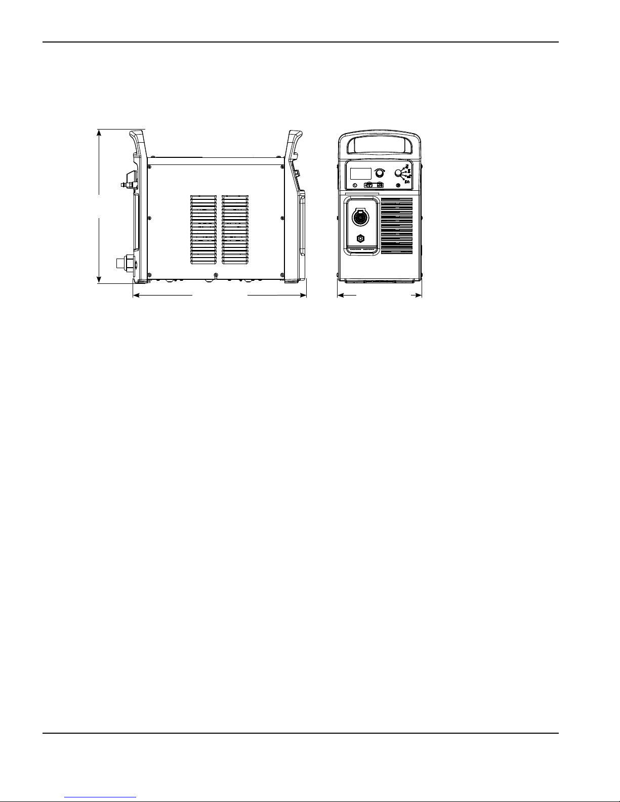
Power supply dimensions
17.0 in
(432 mm)
19.0 in
(483 mm)
9.2 in
(234 mm)
1-4 powermax
65/85
Service Manual
Page 21

Component weights
65 A CSA 65 A CE 85 A CSA 85 A CE
lbs (kg) lbs (kg) lbs (kg) lbs (kg)
Power supply 54.1 (24.5) 47.0 (21.3) 59.9 (27.2) 50.4 (22.8)
65/85 A
lbs (kg)
Hand torch 25 ft (7.6 m) 6.8 (3.1)
Hand torch 50 ft (15 m) 12.2 (5.5)
Hand torch 75 ft (23 m) 17.6 (8.0)
Machine torch 25 ft (7.6 m) 7.6 (3.4)
Machine torch 50 ft (15 m) 13.2 (6.0)
Machine torch 75 ft (23 m) 18.8 (8.5)
65 A 85 A
lbs (kg) lbs (kg)
Work lead 25 ft (7.6 m) 2.8 (1.3) 6.8 (3.1)
Work lead 50 ft (15 m) 5.0 (2.3) 7.5 (3.4)
Work lead 75 ft (23 m) 6.9 (3.1) 10.6 (4.8)
SPECIFICATIONS
powermax
65/85
Service Manual 1-5
Page 22

SPECIFICATIONS
Powermax65 power supply ratings
Rated open-circuit voltage (U0)
CSA, 1-phase, 3-phase
CE, 3-phase
Output characteristic
1
Rated output current (I2) 20 – 65 A
Rated output voltage (U2) 139 VDC
CSA 296 VDC
CE 270 VDC
Drooping
Duty cycle at 40° C (104° F)
(See data plate on power supply
for more information on duty
cycle.)
CSA
CE
50% @ 65 A, 230 – 600 V, 1/3 PH
40% @ 65 A, 200 – 208 V, 1/3 PH
100% @ 46 A, 230 – 600 V, 1/3 PH
50% @ 65 A, 380/400 V, 3 PH
100% @ 46 A, 380/400 V, 3 PH
Operating temperature 14° to 104° F (-10° to 40° C)
Storage temperature -13° to 131° F (-25° to 55° C)
Power factor
200 – 480 V CSA, 1-phase
200 – 600 V CSA, 3-phase
380/400 V CE, 3-phase
R
– Short Circuit Ratio (CE models only) U1 – Volts AC rms, 3PH R
sce
0.99 – 0.97
0.94 – 0.73
0.94
400 VAC 225.7
EMC classification CISPR 11 (CE models only)4Class A
Input voltage (U1)/ Input
current (I1) at rated output (U
, I
MAX
) (See Section 2
2 MAX
Power Supply Setup for more
information.)
2
CSA
CE
200/208/240/480 V, 1 PH, 50/60 Hz
52/50/44/22 A
200/208/240/480/600 V, 3 PH, 50/60 Hz
32/31/27/13/13 A
2,3
380/400 V, 3 PH, 50/60 Hz
15.5/15 A
Gas type Air Nitrogen
sce
Gas quality Clean, dry, oil-free per
ISO 8573-1 Class 1.2.2
Recommended gas inlet flow
rate/pressure
Cutting: 400 scfh , 6.7 scfm (190 slpm) @ 85 psi (5.9 bar)
Gouging: 450 scfh, 7.5 scfm (210 slpm) @ 70 psi (4.8 bar)
1-6 powermax
99.95% pure
65/85
Service Manual
Page 23

SPECIFICATIONS
1
Defined as a plot of output voltage versus output current.
2
Equipment complies with IEC 61000-3-12 provided that the short-circuit power Ssc is greater than or equal to 2035
KVA at the interface point between the user’s supply and the public system. It is the responsibility of the installer or
user of the equipment to ensure, by consultation with the distribution network operator if necessary, that the equipment
is connected only to a supply with a short-circuit power S
3
Equipment complies with IEC 61000-3-11 provided that the supply impedance, Zmax, is 0.201 or less. It is the
responsibility of the installer or user of the equipment to ensure, by consultation with the distribution network operator
if necessary, that the equipment is connected only to a supply with a impedance of 0.201 or less.
4
WARNING: This Class A equipment is not intended for use in residential locations where the electrical power is
provided by the public low-voltage supply system. There may be potential difficulties in ensuring electromagnetic
compatibility in those locations, due to conducted as well as radiated disturbances.
greater than or equal to 2035 KVA.
sc
powermax
65/85
Service Manual 1-7
Page 24

SPECIFICATIONS
Powermax85 power supply ratings
Rated open-circuit voltage (U0)
CSA, single-phase, 3-phase
CE, 3-phase
Output characteristic
1
Drooping
Rated output current (I2) 25 – 85 A
Rated output voltage (U2) 143 VDC
CSA
CE
305 VDC
270 VDC
Duty cycle at 40° C (104° F)
(See data plate on power supply
for more information on duty
cycle.)
CSA
60% @ 85 A, 230 – 600 V, 3 PH
60% @ 85 A, 480 V, 1 PH
50% @ 85 A, 240 V, 1 PH
50% @ 85 A 200 – 208 V, 3 PH
40% @ 85 A 200 – 208 V, 1 PH
100% @ 66 A, 230 – 600 V, 1/3 PH
CE
60% @ 85 A, 380/400 V, 3 PH
100% @ 66 A, 380/400 V, 3 PH
Operating temperature 14° to 104° F (-10° to 40° C)
Storage temperature -13° to 131° F (-25° to 55° C)
Power factor
200 – 480 V CSA, 1-phase
200 – 600 V CSA, 3-phase
380/400 V CE, 3-phase
R
– Short Circuit Ratio (CE models only) U1 – Volts AC rms, 3PH R
sce
0.99 – 0.96
0.94 – 0.76
0.94
400 VAC 225.7
EMC classification CISPR 11 (CE models only)4Class A
Input voltage (U1)/ Input
current (I1) at rated output (U
, I
MAX
) (See Section 2
2 MAX
Power Supply Setup for more
information.)
2
CSA
CE
200/208/240/480 V, 1 PH, 50/60 Hz
70/68/58/29 A
200/208/240/480/600 V, 3 PH, 50/60 Hz
42/40/35/18/17 A
2,3
380/400 V, 3 PH, 50/60 Hz
20.5/19.5 A
sce
Gas type Air Nitrogen
Gas quality Clean, dry, oil-free per
ISO 8573-1 Class 1.2.2
Recommended gas inlet flow
rate/pressure
Cutting: 400 scfh , 6.7 scfm (190 slpm) @ 85 psi (5.9 bar)
Gouging: 450 scfh, 7.5 scfm (210 slpm) @ 70 psi (4.8 bar)
1-8 powermax
99.95% pure
65/85
Service Manual
Page 25

SPECIFICATIONS
1
Defined as a plot of output voltage versus output current.
2
Equipment complies with IEC 61000-3-12 provided that the short-circuit power Ssc is greater than or equal to 2035
KVA at the interface point between the user’s supply and the public system. It is the responsibility of the installer
or user of the equipment to ensure, by consultation with the distribution network operator if necessary, that the
equipment is connected only to a supply with a short-circuit power S
3
Equipment complies with IEC 61000-3-11 provided that the supply impedance, Zmax, is 0.201 or less. It is the
responsibility of the installer or user of the equipment to ensure, by consultation with the distribution network operator
if necessary, that the equipment is connected only to a supply with a impedance of 0.201 or less.
4
WARNING: This Class A equipment is not intended for use in residential locations where the electrical power is
provided by the public low-voltage supply system. There may be potential difficulties in ensuring electromagnetic
compatibility in those locations, due to conducted as well as radiated disturbances.
greater than or equal to 2035 KVA.
sc
powermax
65/85
Service Manual 1-9
Page 26
SPECIFICATIONS
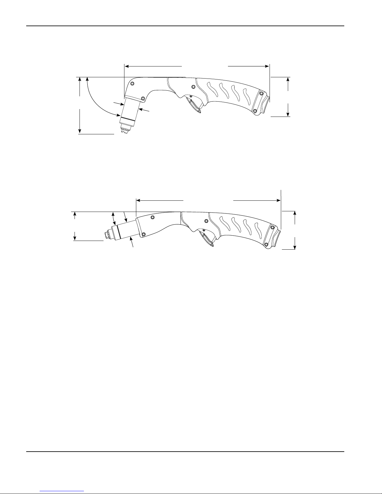
H65/H85 75° hand torch dimensions
9.9 in (25.2 cm)
75°
3.8 in
(9.8 cm)
angle
1.0 in
(2.5 cm)
H65s/H85s 15° hand torch dimensions
15°
1.9 in
(4.7 cm)
angle
1.0 in
(2.5 cm)
2.6 in
(6.6 cm)
10.2 in (25.9 cm)
2.6 in
(6.6 cm)
1-10 powermax
65/85
Service Manual
Page 27
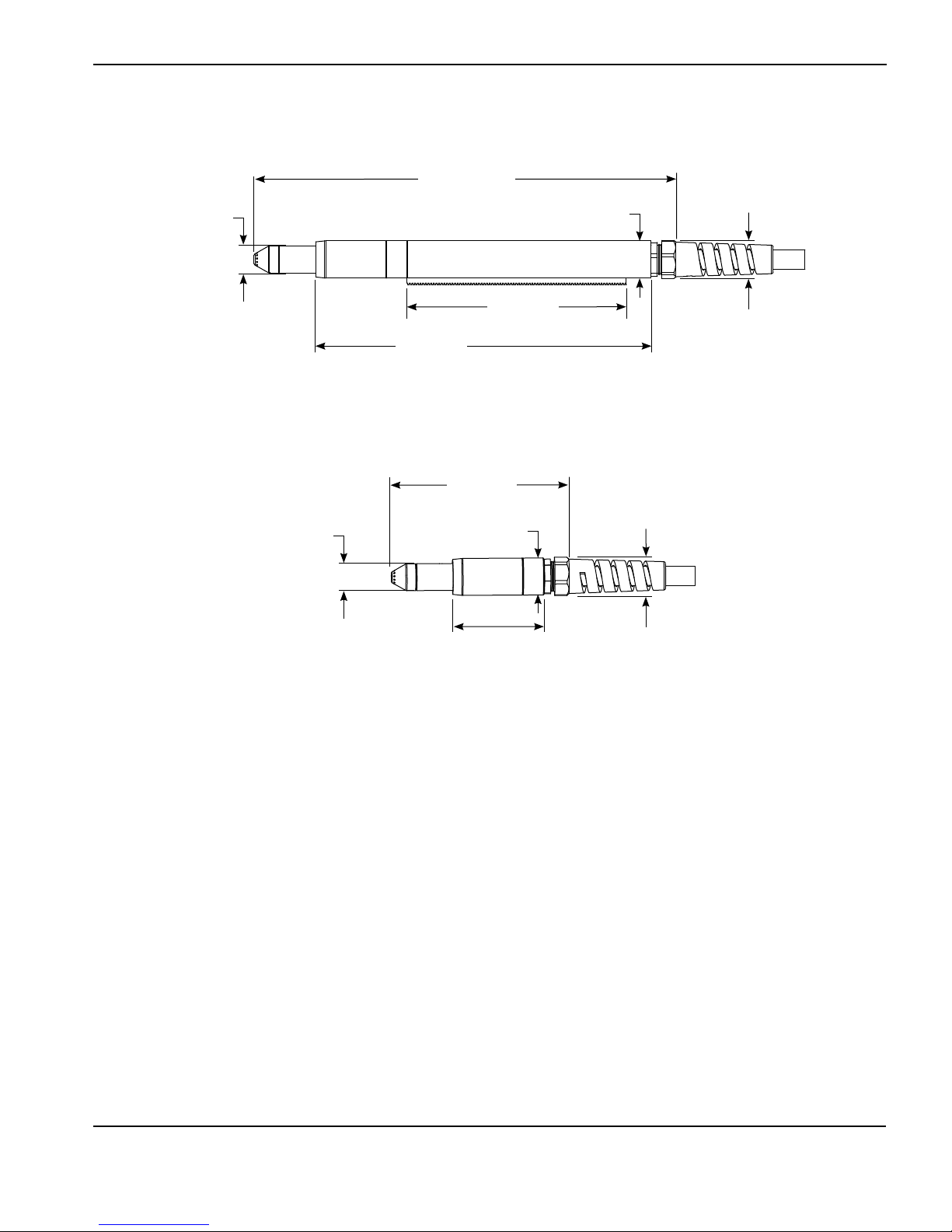
M65/M85 full-length machine torch dimensions
15.6 in
(39.6 cm)
1.0 in
(2.5 cm)
8.1 in
(20.6 cm)
12.3 in
(31.3 cm)
(3.5 cm)
M65m/M85m mini-machine torch dimensions
6.6 in
(16.8 cm)
SPECIFICATIONS
1.4 in
1.4 in (3.6 cm) outer
dimension, 1.3 in
(3.3cm) flat sides
1.0 in
(2.5 cm)
1.4 in
(3.5 cm)
3.3 in
(8.4 cm)
1.4 in (3.6 cm) outer
dimension, 1.3 in
(3.3cm) flat sides
powermax
65/85
Service Manual 1-11
Page 28

SPECIFICATIONS
Powermax65 cutting specifications
Handheld cut capacity (material thickness)
Recommended cut capacity at 20 ipm (500 mm/min)* 3/4 in (19 mm)
Recommended cut capacity at 10 ipm (250 mm/min)* 1 in (25 mm)
Severance capacity at 5 ipm (125 mm/min)* 1-1/4 in (32 mm)
Pierce capacity (material thickness)
Pierce capacity for handheld cutting, or mechanized
cutting with torch height control
Pierce capacity for mechanized cutting without torch
height control
Maximum cut speed** (mild steel)
1/4 in (6 mm) 145 ipm (4000 mm/min)
1/2 in (12 mm) 50 ipm (1400 mm/min)
3/4 in (19 mm) 24 ipm (600 mm/min)
1 in (25 mm) 12 ipm (320 mm/min)
Gouging capacity
Metal removal rate on mild steel 10.7 lbs/hr (4.8 kg/hr)
Duramax series torch weights (refer to 1-5 Component weights)
Duty cycle and voltage information (refer to 1-6 Powermax65 power supply ratings)
5/8 in (16 mm)
1/2 in (12 mm)
* Cut capacity speeds are not necessarily maximum speeds. They are the speeds that must be achieved to be rated at
that thickness.
** Maximum cut speeds are the results of Hypertherm’s laboratory testing. Actual cutting speeds may vary based on
different cutting applications.
1-12 powermax
65/85
Service Manual
Page 29

Powermax85 cutting specifications
Handheld cut capacity (material thickness)
Recommended cut capacity at 20 ipm (500 mm/min)* 1 in (25 mm)
Recommended cut capacity at 10 ipm (250 mm/min)* 1-1/4 in (32 mm)
Severance capacity at 5 ipm (125 mm/min)* 1-1/2 in (38 mm)
Pierce capacity (material thickness)
Pierce capacity for handheld cutting, or mechanized
cutting with torch height control
Pierce capacity for mechanized cutting without torch
height control
Maximum cut speed** (mild steel)
1/4 in (6 mm) 200 ipm (5500 mm/min)
1/2 in (12 mm) 70 ipm (2000 mm/min)
3/4 in (19 mm) 36 ipm (900 mm/min)
1 in (25 mm) 21 ipm (550 mm/min)
1-1/4 in (32 mm) 13 ipm (330 mm/min)
Gouging capacity
Metal removal rate on mild steel 19.5 lbs/hr (8.8 kg/hr)
Duramax series torch weights (refer to 1-5 Component weights)
Duty cycle and voltage information (refer to 1-8 Powermax85 power supply ratings)
3/4 in (19 mm)
5/8 in (16 mm)
SPECIFICATIONS
* Cut capacity speeds are not necessarily maximum speeds. They are the speeds that must be achieved to be rated at
that thickness.
** Maximum cut speeds are the results of Hypertherm’s laboratory testing. Actual cutting speeds may vary based on
different cutting applications.
powermax
65/85
Service Manual 1-13
Page 30

SPECIFICATIONS
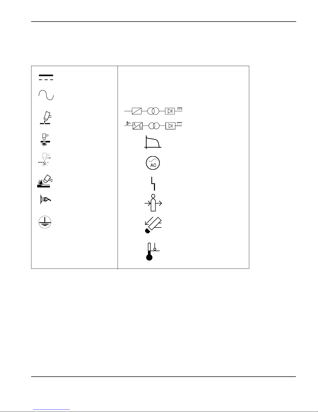
Symbols and markings
Your Hypertherm product may have one or more of the following markings on or near the data plate. Due to differences
and conflicts in national regulations, not all marks are applied to every version of a product.
S mark symbol
The S mark symbol indicates that the power supply and torch are suit able for operations carried out in en vi ron ments with increased hazard of elec tri cal shock per IEC 60974-1.
CSA mark
Hypertherm products with a CSA mark meet the United States and Canadian regulations for product safety. The products
were evaluated, tested, and certified by CSA-International. Alternatively the product may have amark by one of the other
Nationally Recognized Testing Laboratories (NRTL) accredited in both the United States and Canada, such as Underwriters
Laboratories, Incorporated (UL) or TÜV.
CE marking
The CE marking signifies the manufacturer’s declaration of conformity to applicable European directives andstandards.
Only those versions of Hypertherm products with a CE marking located on or near the dataplate have been tested for
compliance with the European Low Voltage Directive and the European Electromagnetic Compatibility (EMC) Directive.
EMC filters needed to comply with the European EMC Directive are incorporated within versions of the product with a CE
marking.
GOST-R mark
CE versions of Hypertherm products that include a GOST-R mark of conformity meet the product safety andEMC
requirements for export to the Russian Federation.
c-Tick mark
CE versions of Hypertherm products with a c-Tick mark comply with the EMC regulations required for sale inAustralia and
New Zealand.
CCC mark
The China Compulsory Certification (CCC) mark indicates that the product has been tested and found compliant with
product safety regulations required for sale in China.
1-14 powermax
65/85
Service Manual
Page 31
SPECIFICATIONS
IEC symbols
The following symbols may appear on the power supply data plate, control labels, switches, LEDs, and LCD screen.
Direct current (DC)
Alternating current
(AC)
Plasma torch cutting
Plate metal cutting
Expanded metal
cutting
Gouging
AC input power
connection
The terminal for the
external protective
(earth) conductor
l
O
1~
f
1
f
2
AC
Power is ON
Power is OFF
An inverter-based power
source, either 1-phase or
3-phase
Volt/amp curve, “drooping”
characteristic
Power is ON (LED)
System fault (LED)
Inlet gas pressure fault
(LCD)
Missing or loose
consumables (LCD)
powermax
65/85
Power supply is out of
temperature range (LCD)
Service Manual 1-15
Page 32

SPECIFICATIONS
1-16 powermax
65/85
Service Manual
Page 33

Section 2
POWER SUPPLY SETUP
In this section:
Unpack the Powermax65 or Powermax85 system .........................................................................................................................2-2
Claims .............................................................................................................................................................................................2-2
Contents .........................................................................................................................................................................................2-3
Position the power supply.....................................................................................................................................................................2-4
Prepare the electrical power ................................................................................................................................................................2-4
Install a line-disconnect switch .................................................................................................................................................2-5
Requirements for grounding ......................................................................................................................................................2-5
Power connection for the Powermax65 ............................................................................................................................................2-6
Single-phase power cord (not for CE model) ..................................................................................................................................2-7
Three-phase power cord — plug installation....................................................................................................................................2-7
Power connection for the Powermax85 ............................................................................................................................................2-8
Single-phase power cord (not for CE model) ..................................................................................................................................2-9
Single-phase power cord installation ................................................................................................................................... 2-10
Three-phase power cord — plug installation................................................................................................................................. 2-11
Extension cord recommendations .................................................................................................................................................... 2-11
Extension cord specifications ................................................................................................................................................. 2-12
Engine-driven generator recommendations ........................................................................................................................ 2-13
Prepare the gas supply ....................................................................................................................................................................... 2-14
Additional gas filtration ............................................................................................................................................................. 2-14
Connect the gas supply ........................................................................................................................................................... 2-15
2-1 powermax
65/85
Service Manual
Page 34

POWER SUPPLY SETUP
Unpack the Powermax65 or Powermax85 system
1. Verify that all items on your order have been received in good condition. Contact your distributor if any parts are
damaged or missing.
2. Inspect the power supply for damage that may have occurred during shipping. If there is evidence of damage, refer
to “Claims” below. All communications regarding this equipment must include the model number and the serial
number located on the back of the power supply.
3. Before you set up and operate this Hypertherm system, read the separate Safety and Compliance Manual included
with your system for important safety information.
Claims
• Claims for damage during shipment – If your unit was damaged during shipment, youmust file a claim
with the carrier. Hypertherm will furnish you with a copy of the bill oflading upon request. If you need additional
assistance, call the nearest Hypertherm office listed in the front of this manual.
• Claims for defective or missing merchandise – If any component is missing or defective, contact your
Hypertherm distributor. If you need additional assistance, call thenearest Hypertherm office listed in the front of
this manual.
2-2 powermax
65/85
Service Manual
Page 35

Contents
Verify the items in the box against the illustration.
Operator Manual
Quick Setup Card
Registration Card
Setup DVD
Safety Manual
Remote-start pendant (optional)
POWER SUPPLY SETUP
Or
Box with extra
consumables
(located next
to air filter)
powermax
65/85
Service Manual 2-3
Page 36

POWER SUPPLY SETUP
Position the power supply
Locate the power supply near an appropriate power receptacle for your installation: 200–480 volts (CSA 1-phase),
200–600 volts (CSA 3-phase), or 380/400 volts (3-phase CE). The power supply has a 10-foot (3 m) power cord.
Allow at least 10 inches (0.25 m) of space around the power supply for proper ventilation.
The power supply is not suitable for use in rain or snow.
To avoid toppling, do not set the power supply on an incline greater than 10 degrees.
Prepare the electrical power
Hypertherm (designated HYP on the data plate) input current ratings are used to determine conductor sizes for power
connection and installation instructions. The HYP rating is determined under maximum normal operating conditions and
the higher HYP input current value should be used for installation purposes.
The maximum output voltage will vary based on your input voltage and the circuit’s amperage. Because the current draw
varies during startup, slow-blow fuses are recommended as shown in the charts below. Slow-blow fuses can withstand
currents up to 10 times the rated value for short periods of time.
Caution: Protect the circuit with appropriately sized time-delay (slow-blow) fuses and a
line-disconnect switch.
2-4 powermax
65/85
Service Manual
Page 37

POWER SUPPLY SETUP
Install a line-disconnect switch
Use a line-disconnect switch for each power supply so that the operator can turn off the incoming power quickly in an
emergency. Locate the switch so that it is easily accessible to the operator. Installation must be performed by a licensed
electrician according to national and local codes. The interrupt level of the switch must equal or exceed the continuous
rating of the fuses. In addition, the switch should:
• Isolate the electrical equipment and disconnect all live conductors from the incoming supply voltage when in the
OFF position.
• Have one OFF and one ON position that are clearly marked with O (OFF) and I (ON).
• Have an external operating handle that can be locked in the OFF position.
• Contain a power-operated mechanism that serves as an emergency stop.
• Have appropriate slow-blow fuses installed. See 2-6 Power connection for the Powermax65 or 2-8 Power
connection for the Powermax85 for recommended fuse sizes.
Requirements for grounding
To ensure personal safety, proper operation, and to reduce electromagnetic interference (EMI), the power supply must
be properly grounded.
• The power supply must be grounded through the power cord according to national and local electrical codes.
• Single-phase service must be of the 3-wire type with a green or green/yellow wire for the protective earth
ground and must comply with national and local requirements. Do not use a 2-wire service.
• Three-phase service must be of the 4-wire type with a green or green/yellow wire for protective earth ground
and must comply with national and local requirements.
• Refer to the separate Safety and Compliance Manual included with your system for more information on
grounding.
powermax
65/85
Service Manual 2-5
Page 38

POWER SUPPLY SETUP
Power connection for the Powermax65
The Powermax65 CSA model is a universal power supply that can configure itself to operate with AC voltages from 200
to 600, 1- or 3-phase. The CE model is 380/400 V, 3-phase only. The rated output is 25 – 65A, 139 VDC.
CSA model Single-phase Three-phase
Input voltage 200-208 230-240 480 200-208 230-240 400 480 600
Input current at 9.0
kw output
Input current
during arc stretch
Fuse (slow-blow) 80 80 40 50 50 30 25 25
CE model Three-phase
Input voltage 380/400
Input current at 9.0
kw output
Input current
during arc stretch
Fuse (slow-blow) 30
52 44 22 32 27 15 13 13
74 74 38 45 45 27 23 23
15.5/15
27
2-6 powermax
65/85
Service Manual
Page 39
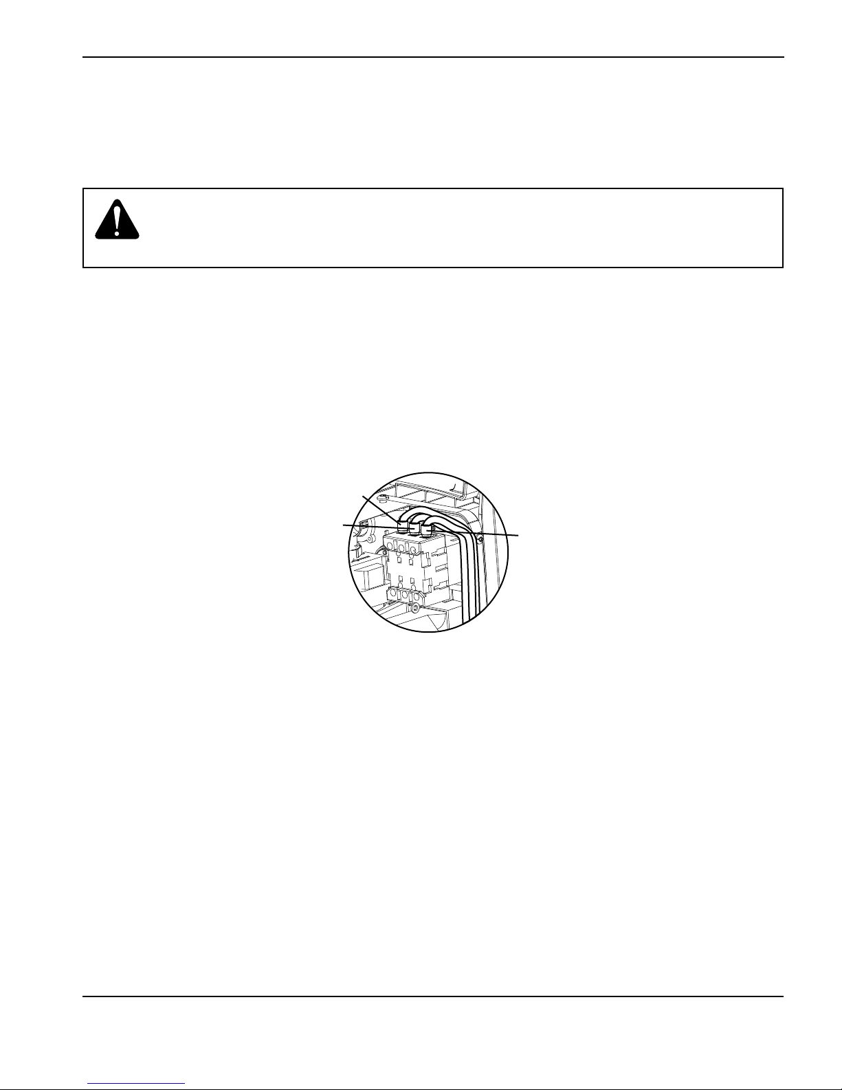
POWER SUPPLY SETUP
Single-phase power cord (not for CE model)
To operate your Powermax65 on 1-phase power, you will need to install an appropriate power cord. Refer to 2-10 Singlephase power cord installation for instructions.
Caution: When using the Powermax65 CSA model power supply (CE model is 3-phase
only) with a 1-phase power source, replace the supplied power cord with an
8 AWG (10 mm2) 3-wire power cord. The power cord must be connected by a
licensed electrician.
Three-phase power cord — plug installation
The Powermax65 power supplies are shipped with an 8 AWG 4-wire power cord on CSA models. A 2.5 mm2, 4-wire
HAR power cord is provided on CE models. To operate the Powermax65, use a plug that meets national and local
electrical codes. The plug must be connected to the power cord by a licensed electrician.
The procedure is similar to installing a single-phase power cord as shown in the section 2-10 Single-phase power cord
installation. The figure below shows the additional wire connected to L3.
L2
L1
L3
powermax
65/85
Service Manual 2-7
Page 40

POWER SUPPLY SETUP
Power connection for the Powermax85
The Powermax85 CSA model is a universal power supply that can configure itself to operate with AC voltages from 200
to 600, 1- or 3-phase. The CE model is 380/400 V, 3-phase only. The rated output is 25 – 85A, 143 VDC.
CSA model Single-phase Three-phase
Input voltage 200-208 230-240 480 200-208 230-240 400 480 600
Input current at
12.2 kw output
Input current
during arc stretch
Fuse (slow-blow) 100 100 50 60 60 40 30 30
CE model Three-phase
Input voltage 380/400
Input current at
12.2 kw output
Input current
during arc stretch
Fuse (slow-blow) 40
70 60 29 42 36 21 18 17
98 98 50 60 60 38 31 30
20.5/20
38
2-8 powermax
65/85
Service Manual
Page 41

POWER SUPPLY SETUP
Single-phase power cord (not for CE model)
To operate your Powermax85 on 1-phase power, you will need to install an appropriate power cord. Refer to 2-10 Singlephase power cord installation for instructions.
Caution: When using the Powermax85 CSA model power supply (CE model is 3-phase
only) with a 1-phase power source, replace the supplied power cord with a 6
AWG (16 mm2) 3-wire power cord. The power cord must be connected by a
licensed electrician.
powermax
65/85
Service Manual 2-9
Page 42

POWER SUPPLY SETUP
Single-phase power cord installation
Strip and prepare the power cord wires as shown below.
14.5 in (368 mm)
L1
Ground
6 in (152 mm)
L2
#10
Route lead through
strain relief and tighten
L1
L2
Power switch
Ground screw
2-10 powermax
65/85
Service Manual
Page 43

POWER SUPPLY SETUP
Three-phase power cord — plug installation
The Powermax85 power supplies are shipped with an 8 AWG 4-wire power cord on CSA models. A 4 mm2, 4-wire
HAR power cord is provided on CE models. To operate the Powermax85, use a plug that meets national and local
electrical codes. The plug must be connected to the power cord by a licensed electrician.
The procedure is similar to installing a single-phase power cord as shown in the section 2-10 Single-phase power cord
installation. The figure below shows the additional wire connected to L3.
L1
L2
L3
Extension cord recommendations
Any extension cord must have an appropriate wire size for the cord length and system voltage. Usea cord that meets
national and local codes.
The table on the next page provides the recommended gauge sizes for various lengths and input voltages. The lengths
in the tables are the length of the extension cord only; they do not include the power supply’s power cord.
powermax
65/85
Service Manual 2-11
Page 44

POWER SUPPLY SETUP
Extension cord specifications
Extension cord length
< 10 ft
(< 3 m)
10 – 25 ft
(3 – 7.5 m)
25 – 50 ft
(7.5 – 15 m)
50 – 100 ft
(15 – 30 m)
100 – 150 ft
(30 – 45 m)
65 A CSA
Input voltage
(VAC) Phase AWG (mm2) AWG (mm2) AWG (mm2) AWG (mm2) AWG (mm2)
200–240 1 8 (10) 8 (10) 8 (10) 6 (16) 4 (25)
480 1 12 (4) 12 (4) 12 (4) 10 (6) 10 (6)
200–240 3 10 (6) 10 (6) 10 (6) 8 (10) 6 (16)
400/480 3 12 (4) 12 (4) 12 (4) 12 (4) 12 (4)
600 3 12 (4) 12 (4) 12 (4) 12 (4) 12 (4)
65 A CE
Input voltage
(VAC) Phase mm
2
mm
2
mm
2
mm
2
mm
2
380 3 4 4 4 4 4
400 3 4 4 4 4 4
85 A CSA
Input voltage
(VAC) Phase AWG (mm2) AWG (mm2) AWG (mm2) AWG (mm2) AWG (mm2)
200–240 1 6 (16) 6 (16) 6 (16) 4 (25) 2 (35)
480 1 10 (6) 10 (6) 10 (6) 8 (10) 8 (10)
200–240 3 8 (10) 8 (10) 8 (10) 6 (16) 4 (25)
400/480 3 10 (6) 10 (6) 10 (6) 10 (6) 10 (6)
600 3 10 (6) 10 (6) 10 (6) 10 (6) 10 (6)
85 A CE
Input voltage
(VAC) Phase mm
2
mm
2
mm
2
mm
2
mm
380 3 6 6 6 6 6
400 3 6 6 6 6 6
2
2-12 powermax
65/85
Service Manual
Page 45

POWER SUPPLY SETUP
Engine-driven generator recommendations
Generators used with the Powermax65 or Powermax85 should satisfy the following requirements:
CSA
• 1-phase, 50/60 Hz, 230/240 VAC
• 3-phase, 50/60 Hz, 200-600 VAC (480 VAC recommended for best performance)
CE
• 3-phase, 50/60 Hz, 380/400 VAC (400 VAC recommended for best performance)
Engine drive
rating
20 kw 85 A Full
15 kw 70 A Limited
15 kw 65 A Full
12 kw 65 A Limited
12 kw 40 A Full
8 kw 40 A Limited
8 kw 30 A Full
Note: Based on the generator rating, age, and condition, adjust the cutting current as needed.
If a fault occurs while using a generator, turning the power switch quickly to OFF and then to ON again
(sometimes called a “quick reset”) may not clear the fault. Instead, turn OFF the power supply and wait 30 to
45 seconds before turning ON again.
System output
current
Performance
(arc stretch)
powermax
65/85
Service Manual 2-13
Page 46

POWER SUPPLY SETUP
Prepare the gas supply
The gas supply can be shop-compressed or cylinder-compressed. A high-pressure regulator must be used on either
type of supply and must be capable of delivering gas to the air inlet on the power supply.
If the supply quality is poor, cut speeds decrease, cut quality deteriorates, cutting thickness capability decreases, and
the life of the consumables shortens. For optimal performance, the gas should be compliant with ISO8573-1:2010,
Class 1.2.2 (that is, it should have a maximum number of solid particulate per m3 of <20,000 for particle sizes in the
range of 0.1-0.5 microns, <400 for particle sizes in the range of 0.5-1 microns, and <10 for particle sizes in the range
of 1-5 microns). The maximum water vapor dew point should be <-40° C (-40° F). The maximum oil (aerosol, liquid, and
vapor) content should be less than 0.1 mg/m3.
Additional gas filtration
When site conditions introduce moisture, oil, or other contaminants into the gas line, use a 3-stage coalescing filtration
system, such as the Eliminizer filter kit (part number 128647) available from Hypertherm distributors. A 3-stage filtering
system works as shown below toclean contaminants from the gas supply.
Water and particle filter
Gas supply
The filtering system should be installed between the gas supply and the power supply. Additional gas filtration may
increase the required minimum inlet pressure.
Oil filter Oil vapor filter
Powermax65
Powermax85
2-14 powermax
65/85
Service Manual
Page 47

POWER SUPPLY SETUP
Connect the gas supply
Connect the gas supply to the power supply using an inert-gas hose with a 3/8 inch (9.5mm) internal diameter and a
1/4NPT quick-disconnect coupler, or a 1/4 NPT x G-1/4 BSPP (CE units) quick-disconnect coupler.
The recommended inlet pressure while gas
is flowing is 85 - 135 psi (5.9 - 9.3 bar).
WARNING
Do not allow the gas supply pressure to exceed 135 psi (9.3 bar). The filter bowl may explode if this
pressure is exceeded.
powermax
65/85
Service Manual 2-15
Page 48

POWER SUPPLY SETUP
Minimum inlet pressure (while gas is flowing)
This table shows the minimum required inlet pressure when the recommended inlet pressure is not available.
Torch lead length
25 ft (7.62 m) 50 ft (15.24 m) 75 ft (22.86 m)
Cutting 75 psi (5.2 bar) 80 psi (5.5 bar) 85 psi (5.9 bar)
Gouging 60 psi (4.1 bar) 65 psi (4.5 bar) 70 psi (4.8 bar)
Gas flow rates
Cutting 400 scfh, 6.7 scfm (190 slpm) at a minimum 85 psi (5.9 bar)
Gouging 450 scfh, 7.5 scfm (210 slpm) at a minimum 70 psi (4.8 bar)
2-16 powermax
65/85
Service Manual
Page 49

Section 3
TORCH SETUP
In this section:
Introduction ..............................................................................................................................................................................................3-2
Consumable life .......................................................................................................................................................................................3-2
Hand torch setup .................................................................................................................................................................................... 3-3
Choose the hand torch consumables .....................................................................................................................................3-4
Hand torch consumables ...........................................................................................................................................................3-5
Install the hand torch consumables ..........................................................................................................................................3-6
Machine torch setup...............................................................................................................................................................................3-7
Converting an M65/M85 torch to an M65m/M85m torch .................................................................................................3-8
Mount the torch .......................................................................................................................................................................... 3-10
Choose the machine torch consumables ............................................................................................................................ 3-12
Machine torch consumables ................................................................................................................................................... 3-12
Install the machine torch consumables ................................................................................................................................ 3-15
Aligning the torch ...................................................................................................................................................................... 3-15
Connecting an optional remote-start pendant ...................................................................................................................3-16
Connecting an optional machine interface cable ............................................................................................................... 3-17
Connecting the torch lead ................................................................................................................................................................. 3-22
Using the cut charts ............................................................................................................................................................................ 3-23
Estimated kerf-width compensation ...................................................................................................................................... 3-24
85 A shielded consumables ................................................................................................................................................... 3-26
65 A shielded consumables ................................................................................................................................................... 3-30
45 A shielded consumables ................................................................................................................................................... 3-34
FineCut® consumables ............................................................................................................................................................ 3-38
85 A unshielded consumables ............................................................................................................................................... 3-41
65 A unshielded consumables ............................................................................................................................................... 3-45
45 A unshielded consumables ............................................................................................................................................... 3-49
3-1 powermax
65/85
Service Manual
Page 50

TORCH SETUP
Introduction
Duramax™ series handheld and machine torches are available for the Powermax65 and Powermax85 systems. The
FastConnectTM quick-disconnect system makes it easy to remove the torch for transport or to switch from one torch
to the other if your applications require the use of different torches. The torches are cooled by ambient air and do not
require special cooling procedures.
This section explains how to set up your torch and choose the appropriate consumables for the job.
Consumable life
How often you need to change the consumables on your Powermax65 or Powermax85 will depend on a number of
factors:
• The thickness of the metal being cut.
• The average length of the cut.
• Whether you are doing machine or hand cutting.
• The air quality (presence of oil, moisture, or other contaminants).
• Whether you are piercing the metal or starting cuts from the edge.
• Proper torch-to-work distance when gouging or cutting with unshielded consumables.
• Proper pierce height.
• Whether you are cutting in “continuous pilot arc” mode or normal mode. Cutting with a continuous pilot arc
causes more consumable wear.
Under normal conditions, the electrode will wear out first during machine cutting and the nozzle will wear out first when
hand cutting.
A general rule is that a set of consumables lasts approximately 2 to 3 hours of actual “arc on” time for hand cutting,
depending on these factors. For mechanized cutting, consumables should last about 3 to 5 hours.
You will find more information about proper cutting techniques in Section 4, Operation.
3-2 powermax
65/85
Service Manual
Page 51

Hand torch setup
H65/H85
TORCH SETUP
H65s/H85s
Consumables
Consumables
Safety trigger
Safety trigger
powermax
65/85
Service Manual 3-3
Page 52

TORCH SETUP
Choose the hand torch consumables
Powermax systems with the Duramax series H65, H85, H65s, or H85s torch are shipped with a full set of cutting
consumables pre-installed. Hypertherm also includes spare cutting electrodes and nozzles, and gouging consumables in
the consumables box.
Both styles of hand torches shown above use the same consumables.
Hand torches use shielded consumables. Therefore, you can drag the torch tip along the metal.
Consumables for hand cutting are shown on the next page. Notice that the retaining cap and electrode are the same for
cutting, gouging, and FineCut® applications. Only the shield, nozzle, and swirl ring are different.
For the best cut quality on thin materials, you may prefer to use FineCut consumables, or use a 45A nozzle and reduce
the amperage to that setting.
3-4 powermax
65/85
Service Manual
Page 53

Hand torch consumables
Drag-cutting consumables: Powermax65
220818
Shield
Drag-cutting consumables: Powermax85
220818
Shield
220854
Retaining cap
220854
Retaining cap
4
5
A
220941
Nozzle
6
5
A
220819
Nozzle
4
5
A
220941
Nozzle
6
5
A
220819
Nozzle
8
5
A
220842
Electrode
220842
Electrode
TORCH SETUP
220857
Swirl ring
220857
Swirl ring
Gouging consumables
220798
Shield
FineCut® consumables
220931
Shield
220854
Retaining cap
220854
Retaining cap
220816
Nozzle
220797
Nozzle
220930
Nozzle
220842
Electrode
220842
Electrode
220857
Swirl ring
220947
Swirl ring
powermax
65/85
Service Manual 3-5
Page 54
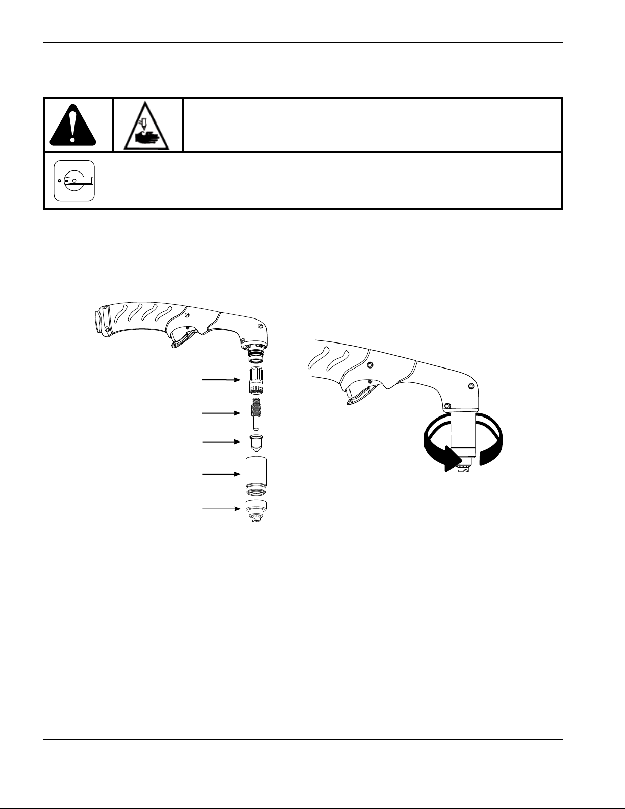
TORCH SETUP
Install the hand torch consumables
WARNING:
INSTANTON TORCHES
PLASMA ARC CAN CAUSE INJURY AND BURNS
The plasma arc comes on im me di ate ly when the torch trigger is
activated. Make sure the power is OFF before changing consumables.
To operate the hand torch, a complete set of consumable parts must be installed: shield, retaining cap, nozzle,
electrode, and swirl ring.
With the power switch in the OFF (O) position, install the torch consumables asshown below.
Swirl ring
Electrode
Nozzle
Retaining cap
Shield
3-6 powermax
65/85
Service Manual
Page 55
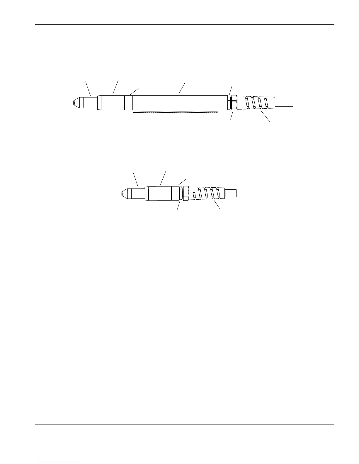
Machine torch setup
M65/M85
Mounting
Consumables
sleeve
Coupler
Positioning sleeve
Strain relief nut
TORCH SETUP
Torch lead
Gear rack Strain relief body
M65m/M85m
Mounting
Consumables
Before using either style of machine torch, you must:
• Mount the torch on your cutting table or other equipment.
• Choose and install the consumables.
• Align the torch.
• Attach the torch lead to the power supply.
• Set up the power supply for remote starting with either the remote-start pendant or a machine interface cable.
sleeve
Coupler
Strain relief nut
Main strain
relief nut
Torch lead
Strain relief body
powermax
65/85
Service Manual 3-7
Page 56

TORCH SETUP
Converting an M65/M85 torch to an M65m/M85m torch
You can convert a full-length machine torch to a mini-machine torch by removing the positioning sleeve.
Note: If you are converting a full-length machine torch to a mini-machine torch and mounting the torch at the same
time, skip this section and follow the instructions in 3-10 Mount the torch.
Refer to the figures in the section 3-7 Machine torch setup and follow these instructions.
Note: While disconnecting and reconnecting the torch parts, maintain the same orientation between the torch
head and torch lead. Twisting the torch head in relation to the torch lead can cause damage.
1. Disconnect the torch lead from the power supply and remove the consumables from the torch.
2. Unscrew the strain relief body from the strain relief nut and slide the strain relief body back along the torch lead.
3. Unscrew the strain relief nut from the positioning sleeve and slide the nut back along the torch lead.
4. Unscrew the positioning sleeve from the coupler.
5. Unscrew the coupler from the mounting sleeve.
6. Remove the three screws from the consumables end of the mounting sleeve and slide the mounting sleeve off the
front of the torch body.
3-8 powermax
65/85
Service Manual
Page 57

TORCH SETUP
Pilot wire
terminal screw
Wire connector for
Torch head
7. Disconnect the wire connector for the cap-sensor switch.
8. Use a #2 Phillips screwdriver to remove the screw that secures the torch’s pilot wire to the torch body.
9. Use 1/4-inch and 3/8-inch wrenches, or adjustable wrenches, to loosen the nut that secures the gas supply line to
the torch lead. Set the torch body aside.
Gas supply line
connection
cap-sensor switch
10. Slide the coupler and positioning sleeve off the front of the torch lead.
11. Slide the coupler over the torch lead.
12. Reconnect the gas line to the torch lead.
13. Reattach the torch’s pilot wire to the torch body using the screw.
14. Reconnect the cap-sensor switch’s wire connector.
15. Slide the mounting sleeve over the front of the torch body. Align the slot on the front of the mounting sleeve (next to
one of the three screw holes) with the cap-sensor plunger on the torch body.
16. Attach the mounting sleeve to the torch body using the three screws.
17. Screw the coupler into the mounting sleeve.
18. Screw the strain relief nut into the coupler.
19. Screw the strain relief body into the strain relief nut.
powermax
65/85
Service Manual 3-9
Page 58
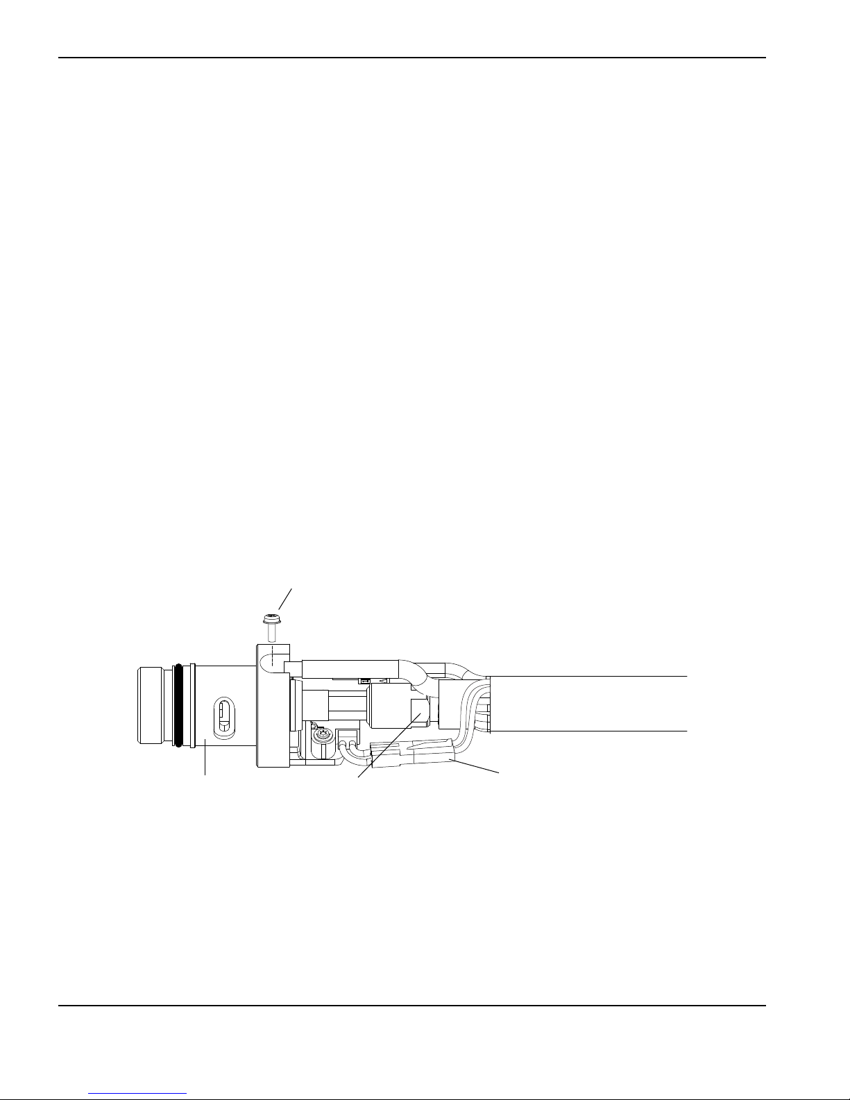
TORCH SETUP
Mount the torch
Depending on the type of cutting table you have, you may or may not need to disassemble the torch to route it through
the track and mount it. If your cutting table’s track is large enough for you to thread the torch through it without removing
the torch body from the lead, do so and then attach the torch to the lifter per the manufacturer’s instructions.
Note: The Duramax machine torches can be mounted on a wide variety of X-Y tables, track burners, pipe bevelers,
and other equipment. Install the torch per the manufacturer’s instructions and follow the instructions below
for disassembly if necessary.
If you need to disassemble and reassemble the torch, refer to the figures in the section 3-7 Machine torch setup and follow
these instructions.
Note: While disconnecting and reconnecting the torch parts, maintain the same orientation between the torch
head and torch lead. Twisting the torch head in relation to the torch lead can cause damage.
1. Disconnect the torch lead from the power supply and remove the consumables from the torch.
2. Unscrew the strain relief body from the strain relief nut and slide the strain relief body back along the torch lead.
3. Unscrew the strain relief nut from the positioning sleeve (full-length machine torch) and slide the nut back along the
torch lead.
4. Unscrew the positioning sleeve from the coupler.
5. Unscrew the coupler from the mounting sleeve.
6. Remove the three screws from the consumables end of the mounting sleeve and slide the mounting sleeve off the
front of the torch body.
Pilot wire
terminal screw
Wire connector for
Torch head
Gas supply line
connection
cap-sensor switch
3-10 powermax
65/85
Service Manual
Page 59

TORCH SETUP
7. Disconnect the wire connector for the cap-sensor switch.
8. Use a #2 Phillips screwdriver to remove the screw that secures the torch’s pilot wire to the torch body.
9. Use 1/4-inch and 3/8-inch wrenches, or adjustable wrenches, to loosen the nut that secures the gas supply line to
the torch lead. Set the torch body aside.
Note: Cover the end of the gas line on the torch lead with tape to keep dirt and other contaminants from
getting in the gas line when you route the lead through the track.
10. Slide the coupler, positioning sleeve (full-length machine torch), strain relief nut, and strain relief body off the front of
the torch lead.
11. If you do not need the gear rack on a full-length machine torch, slide the gear rack from the positioning sleeve
toward the consumables end of the sleeve.
12. Route the torch lead through the cutting table’s track.
13. Slide the strain relief body and strain relief nut over the torch lead.
14. If you are mounting a full-length machine torch, slide the positioning sleeve over the torch head.
15. Slide the coupler over the torch lead.
16. Reconnect the gas line to the torch lead.
17. Reattach the torch’s pilot wire to the torch body using the screw.
18. Reconnect the cap-sensor switch’s wire connector.
19. Slide the mounting sleeve over the front of the torch body. Align the slot on the front of the mounting sleeve (next to
one of the three screw holes) with the cap-sensor plunger on the torch body.
20. Attach the mounting sleeve to the torch body using the three screws.
21. Screw the coupler into the mounting sleeve.
22. If you are mounting a full-length machine torch, screw the positioning sleeve into the coupler.
23. Reconnect the strain relief nut and strain relief body.
24. Attach the torch to the lifter per the manufacturer’s instructions.
powermax
65/85
Service Manual 3-11
Page 60

TORCH SETUP
Choose the machine torch consumables
Powermax systems with the Duramax M65, M85, M65m, or M85m are shipped with a complete set of consumables.
Hypertherm also includes spare electrodes and nozzles. In addition, an ohmic-sensing retaining cap is available for use
with shielded consumables. With unshielded consumables, you must keep the torch a small distance, about .08 inch (2
mm), away from the metal. Unshielded consumables generally have a shorter life than shielded consumables.
Both styles of machine torches use the same consumables.
Machine torch consumables
Mechanized shielded consumables: Powermax65
4
5
A
220941
Nozzle
6
5
220817
Shield
220854
Retaining cap
A
220819
Nozzle
220842
Electrode
220857
Swirl ring
Mechanized shielded with ohmic consumables: Powermax65
4
5
A
220941
Nozzle
6
5
220817
Shield
220953
Ohmic-sensing
retaining cap
A
220819
Nozzle
220842
Electrode
220857
Swirl ring
3-12 powermax
65/85
Service Manual
Page 61

Mechanized unshielded consumables: Powermax65
4
5
A
220941
Nozzle
6
5
220955
Deflector
220854
Retaining cap
A
220819
Nozzle
Electrode
Mechanized shielded consumables: Powermax85
4
5
A
220941
Nozzle
6
5
A
220842
TORCH SETUP
220857
Swirl ring
220817
Shield
220854
Retaining cap
220819
Nozzle
8
5
A
220816
Nozzle
220842
Electrode
Mechanized shielded with ohmic consumables: Powermax85
4
5
A
220941
Nozzle
6
5
A
220817
Shield
220953
Ohmic-sensing
retaining cap
220819
Nozzle
8
5
A
220816
Nozzle
220842
Electrode
220857
Swirl ring
220857
Swirl ring
powermax
65/85
Service Manual 3-13
Page 62
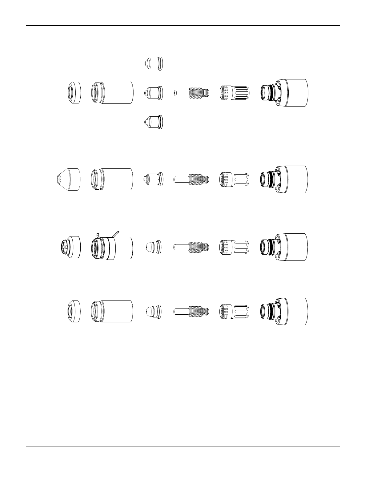
TORCH SETUP
Mechanized unshielded consumables: Powermax85
4
5
A
220941
Nozzle
6
5
A
220955
Deflector
220854
Retaining cap
Gouging consumables
220798
Shield
220854
Retaining cap
FineCut® shielded consumables
220948
Shield
220953
Retaining cap
220819
Nozzle
8
5
A
220816
Nozzle
220797
Nozzle
220930
Nozzle
220842
Electrode
220842
Electrode
220842
Electrode
220857
Swirl ring
220857
Swirl ring
220857
Swirl ring
FineCut® unshielded consumables
220955
Deflector
220854
Retaining cap
220930
Nozzle
220842
Electrode
220857
Swirl ring
3-14 powermax
65/85
Service Manual
Page 63
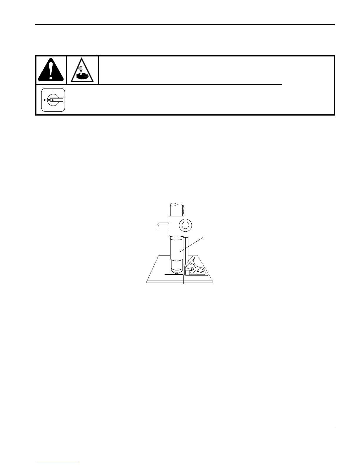
TORCH SETUP
Install the machine torch consumables
WARNING
INSTANT-ON TORCHES
PLASMA ARC CAN CAUSE INJURY AND BURNS
The plasma arc comes on im me di ate ly when the torch is activated. Make sure the
power is OFF before changing the consumables.
To operate the machine torch, a complete set of consumable parts must be installed: shield, retaining cap, nozzle,
electrode, and swirl ring.
With the power switch in the OFF (O) position, install the machine torch consumables in a manner similar to the hand
torch consumables. Refer to 3-6 Install the hand torch consumables.
Aligning the torch
Mount the machine torch perpendicular to the workpiece in order to get a vertical cut. Use a square to align the torch at
0° and 90°.
Torch
0°
90°
powermax
65/85
Service Manual 3-15
Page 64
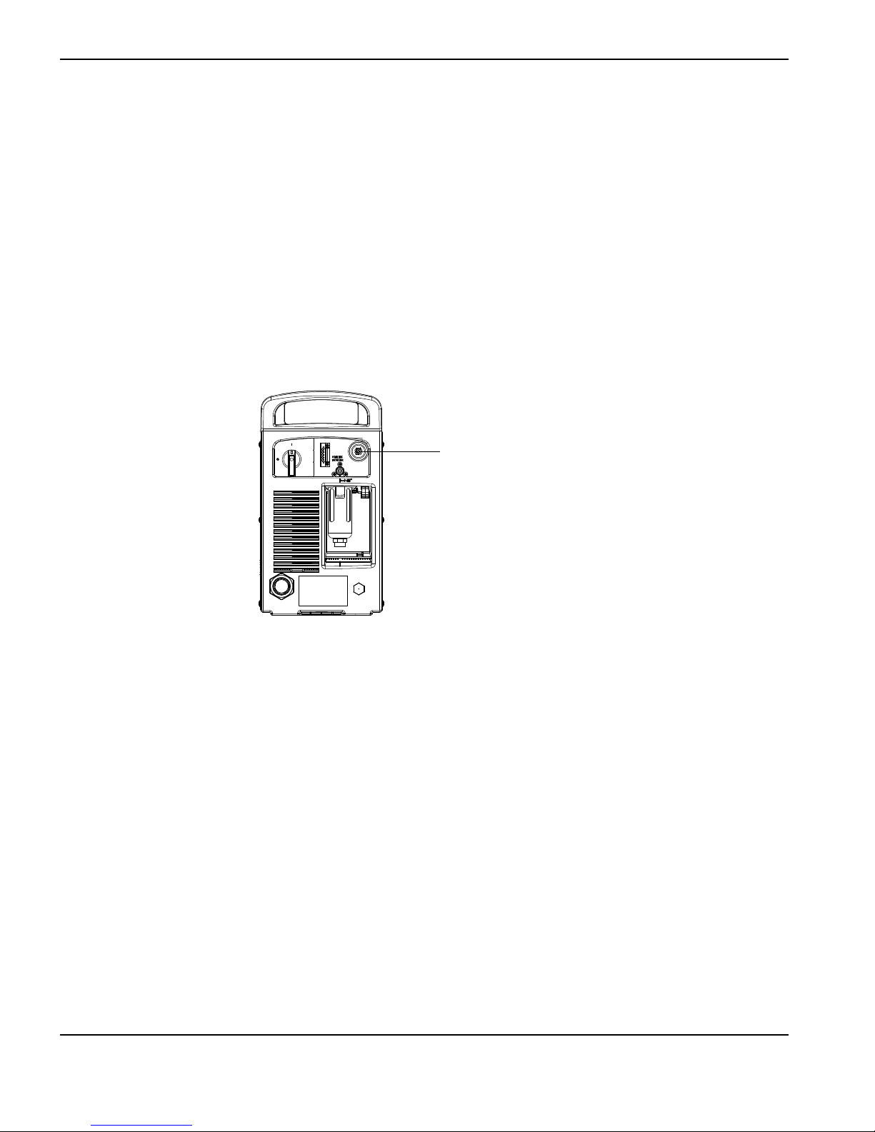
TORCH SETUP
Connecting an optional remote-start pendant
Powermax65 and Powermax85 configurations with a Duramax machine torch can include an optional remote-start
pendant.
• Part number 128650: 25 foot (7.6 m)
• Part number 128651: 50 foot (15 m)
• Part number 128652: 75 foot (23 m)
Remove the receptacle cover and plug the Hypertherm remote-start pendant into the receptacle on the rear of the
power supply.
Note: The remote-start pendant is for use only with a machine torch. It will not operate if a handheld torch is
installed.
Receptacle for the
remote-start pendant or a
machine interface cable.
3-16 powermax
65/85
Service Manual
Page 65

TORCH SETUP
Connecting an optional machine interface cable
The Powermax65 and Powermax85 power supplies are equipped with an optional, factory-installed, five-position voltage
divider that is designed to be safely connected without tools. The built-in voltage divider provides a scaled down arc
voltage of 20:1, 21.1:1, 30:1, 40:1, and 50:1 (maximum output of 18V). An optional receptacle on the rear of the power
supply provides access to the scaled down arc voltage and signals for arc transfer and plasma start.
Note: The factory presets the voltage divider to 50:1. To change the voltage divider to a different setting, refer to 3-20
Setting the five-position voltage divider.
Caution: The factory-installed internal voltage divider provides a maximum of
18 V under open circuit conditions. This is an impedance-protected functional extra low
voltage (ELV) output to prevent shock, energy, and fire under normal conditions at the
machine interface receptacle and under single fault conditions with the machine interface
wiring. The voltage divider is not fault tolerant and ELV outputs do not comply with safety
extra low voltage (SELV) requirements for direct connection to computer products.
Hypertherm offers several choices of machine interface cables for the Powermax65 and Powermax85:
• To use the built-in voltage divider that provides a scaled down arc voltage in addition to signals for arc transfer
and plasma start:
- Use part number 228350 (25 ft, 7.6 m) or 228351 (50 ft, 15 m) for wires terminated with spade
connectors.
- Use part number 123896 (50 ft, 15 m) for a cable terminated with a D-sub connector. (Compatible with
Hypertherm’s Edge Ti and Sensor PHC products.)
• To use signals for arc transfer and plasma start only, use either part number 023206
(25 ft, 7.6 m) or part number 023279 (50 ft, 15 m). These cables have spade connectors as shown below.
powermax
65/85
Service Manual 3-17
Page 66

TORCH SETUP
Note: The cover on the machine interface receptacle prevents dust and moisture from damaging the receptacle
when not in use. This cover should be replaced if damaged or lost (part number 127204).
See Section 6, Parts for more information.
Installation of the machine interface cable must be performed by a qualified service technician. To install a machine
interface cable:
1. Turn OFF the power and disconnect the power cord.
2. Remove the machine interface receptacle’s cover from the rear of the power supply.
3. Connect the Hypertherm machine interface cable to the power supply.
4. If you are using a cable with a D-sub connector on the other end, plug it into the appropriate pin connector on the
torch height controller or CNC. Secure it with the screws on the D-sub connector.
If you are using a cable with wires and spade connectors on the other end, terminate the machine interface
cable inside the electrical enclosure of listed and certified torch height controllers or CNC controllers to prevent
unauthorized access to the connections after installation. Verify that the connections are correct and that all live
parts are enclosed and protected before operating the equipment.
Note: The integration of Hypertherm equipment and customer-supplied equipment including interconnecting cords
and cables, if not listed and certified as a system, is subject to inspection by local authorities at the final
installation site.
The connector sockets for each type of signal available through the machine interface cable are shown in the figure
below. The table provides details about each signal type.
3-18 powermax
65/85
Service Manual
Page 67

TORCH SETUP
6
3
14
13
Refer to the following table when connecting the Powermax65 or Powermax85 to a torch height controller or CNC
controller with a machine interface cable.
Signal Type Notes
Start
(start
plasma)
Transfer
(start
machine
motion)
Input Normally open.
18 VDC open circuit voltage at
START terminals. Requires dry
contact closure to activate.
Output Normally open. Dry contact closure
when the arc transfers.
120 VAC/1 A maximum at the
machine interface relay or switching
device (supplied by the customer).
5
4
12
Connector
sockets
3, 4
12, 14
Cable wires
Green, black
Red, black
Ground Ground 13
Voltage
divider
powermax
Output Divided arc signal of 20:1, 21.1:1,
30:1, 40:1, 50:1 (provides a
maximum of 18 V).
65/85
Service Manual 3-19
5 (-), 6 (+)
Black (-), white (+)
Page 68

TORCH SETUP
Setting the five-position voltage divider
To change the factory preset voltage divider from 50:1 to a different setting:
1. Turn OFF the power supply and disconnect the power cord.
2. Remove the power supply cover.
3. Locate the voltage divider DIP switches on the left side of the power supply.
Note: The figure below shows the default setting (50:1) with the number 4 switch up.
4. Set the DIP switches to one of the following settings and replace the power supply cover.
20:1 21.1:1 30:1 40:1 50:1
3-20 powermax
65/85
Service Manual
Page 69

TORCH SETUP
Accessing raw arc voltage
To access divided raw arc voltage, refer to Field Service Bulletin 807060.
WARNING:
HIGH VOLTAGE AND CURRENT
Connecting directly to the plasma circuit for access to raw arc voltage increases the risk
of shock hazard, energy hazard, and fire hazard in the event of a single fault. The output
voltage and the output current of the circuit are specified on the data plate.
powermax
65/85
Service Manual 3-21
Page 70

TORCH SETUP
Connecting the torch lead
The Powermax65 and Powermax85 are equipped with FastConnectTM, a quick-disconnect system for connecting and
disconnecting handheld and machine torch leads. When connecting or disconnecting a torch, first turn OFF the system.
To connect either torch, push the connector into the receptacle on the front of the power supply.
To remove the torch, press the red button on the connector and pull the connector out of the receptacle.
Red button
3-22 powermax
65/85
Service Manual
Page 71

TORCH SETUP
Using the cut charts
The following sections provide cut charts for each set of mechanized consumables. A consumable diagram with part
numbers precedes each set of charts. For each consumable type, there are Metric and English charts for mild steel,
stainless steel, and aluminum.
Each chart contains the following information:
• Material Thickness — Thickness of the workpiece (metal plate being cut).
• Torch-to-Work Distance — For shielded consumables, the distance between the shield and the workpiece
during cutting. For unshielded consumables, the distance between the nozzle and the workpiece during cutting.
• Initial Pierce Height — Distance between the shield (shielded) or the nozzle (unshielded) and the workpiece
when the torch is triggered, prior to descending to the cut height.
• Pierce Delay Time — Length of time the triggered torch remains stationary at the pierce height before the torch
starts the cutting motion.
• Best Quality Settings (cut speed and voltage) — Settings that provide the starting point for finding the best
cut quality (best angle, least dross, best cut-surface finish). Adjust the speed for your application and table to
obtain the desired result.
• Production Settings (cut speed and voltage) — 80% of the maximum speed ratings. These speeds result in the
greatest number of cut parts, but not necessarily the best possible cut quality.
Note: The arc voltage increases as the consumables wear and the voltage setting should be increased to
maintain the correct Torch-to-Work Distance.
Each cut chart lists hot and cold air flow rates.
• Hot air flow rate — Plasma is on, the system is operating at running current, and the system is in a steady state
at the default system pressure (automatic mode).
• Cold air flow rate — Plasma is off and the system is in a steady state with air flowing through the torch at the
default system pressure.
Note: Hypertherm collected the data under laboratory test conditions using new consumables.
powermax
65/85
Service Manual 3-23
Page 72

TORCH SETUP
Estimated kerf-width compensation
The widths in the tables below are for reference. The data are obtained with the “Best Quality” settings. Differences
between installations and material composition may cause actual results to vary from those shown in the tables.
Estimated kerf-width compensation - Metric (mm)
Thickness (mm)
Process
85A Shielded 1.7 1.8 1.9 2.0 2.2 2.4 2.6
65A Shielded 1.6 1.6 1.8 1.9 2.0 2.2 2.3
45A Shielded 1.1 1.1 1.4 1.5 1.7
FineCut 0.7 0.7 1.3 1.3
85A Unshielded 1.7 1.8 1.9 2.0 2.1 2.1 2.3
65A Unshielded 1.6 1.6 1.7 1.8 1.9 2.0
45A Unshielded 0.5 0.9 1.3 1.3
85A Shielded 1.6 1.8 1.9 2.1 2.3 2.4 2.5
65A Shielded 1.4 1.5 1.8 1.9 2.0 2.2 2.4
45A Shielded 0.9 1.1 1.5 1.6 1.8
FineCut 0.6 0.6 1.4 1.5
85A Unshielded 1.7 1.7 1.8 1.9 2.1 2.2 2.4
65A Unshielded 1.6 1.6 1.8 1.8 1.9 2.0
45A Unshielded 0.5 1.0 1.3 1.5 1.5
85A Shielded 2.0 1.9 2.0 2.1 2.2 2.4 2.6
65A Shielded 1.9 1.9 1.9 2.0 2.1 2.3 2.5
45A Shielded 1.5 1.5 1.6 1.5
85A Unshielded 1.9 1.9 1.9 2.0 2.0 2.1 2.2
65A Unshielded 1.8 1.8 1.8 1.8 1.9 2.0
45A Unshielded 1.6 1.5 1.4 1.5
0.5 1 2 3 6 8 10 12 16 20
Mild Steel
Stainless Steel
Aluminum
3-24 powermax
65/85
Service Manual
Page 73

TORCH SETUP
Estimated kerf-width compensation - English (inches)
Thickness (inches)
Process
85A Shielded 0.068 0.071 0.073 0.078 0.090 0.095 0.100
65A Shielded 0.062 0.065 0.068 0.070 0.076 0.088 0.090 0.091
45A Shielded 0.035 0.054 0.055 0.061 0.065 0.066
FineCut 0.024 0.043 0.049 0.051
85A Unshielded 0.070 0.073 0.075 0.080 0.085 0.090
65A Unshielded 0.062 0.064 0.066 0.068 0.075 0.081
45A Unshielded 0.020 0.050 0.051 0.054 0.057 0.059
85A Shielded 0.080 0.078 0.075 0.080 0.090 0.095 0.100
65A Shielded 0.073 0.074 0.075 0.076 0.083 0.091 0.100
45A Shielded 0.059 0.061 0.065 0.060
85A Unshielded 0.075 0.075 0.075 0.080 0.082 0.088
65A Unshielded 0.070 0.070 0.070 0.070 0.072 0.079
45A Unshielded 0.062 0.058 0.057 0.061
22GA 18GA 14GA 10GA 3/16 1/4 3/8 1/2 5/8 3/4
Mild Steel
Stainless Steel
Aluminum
1/32 1/16 1/8 3/16 1/4 3/8 1/2 5/8 3/4
powermax
65/85
Service Manual 3-25
Page 74
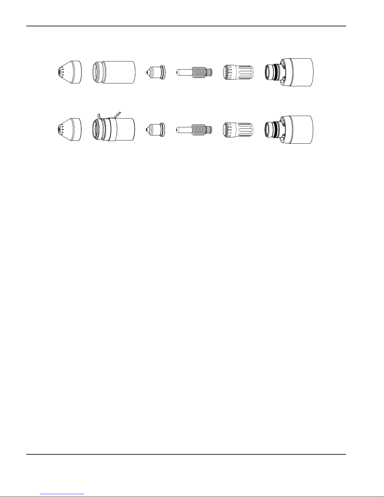
TORCH SETUP
85 A shielded consumables
8
5
A
220817
Shield
220817
Shield
220854
Retaining cap
220953
Ohmic-sensing
retaining cap
220816
Nozzle
8
5
A
220816
Nozzle
220842
Electrode
220842
Electrode
220857
Swirl ring
220857
Swirl ring
3-26 powermax
65/85
Service Manual
Page 75

TORCH SETUP
85A Shielded Air flow rate - slpm/scfh
Mild Steel
Metric
Material
Thickness
Torch-
to-Work
Distance
Initial Pierce
Height
Pierce
Delay
Time
Best Quality Settings Production Settings
Cut Speed Voltage Cut Speed Voltage
mm mm mm % seconds (mm/min) Volts (mm/min) Volts
3
0.1 6800 122 9200 120
4 0.2 5650 122 7300 122
6
8 2500 125 3100 127
10 1680 127 2070 128
12
1.5
16 1.0 870 134 930 133
3.8 250
4.5 300
3600 123 4400 125
0.5
0.7 1280 130 1600 130
20 6.0 400 1.5 570 137 680 136
25
30 200 146 300 144
Edge Start
350 142 450 141
Hot 190 / 400
Cold 235 / 500
English
Material
Thickness
Torch-
to-Work
Distance
Initial Pierce
Height
Pierce
Delay
Time
Best Quality Settings Production Settings
Cut Speed Voltage Cut Speed Voltage
in in % seconds ipm Volts ipm Volts
10GA
3/16 in 0.2 185 123 220 123
1/4 in
0.15 250
3/8 in 70 126 86 127
1/2 in
5/8 in 1.0 35 134 37 133
0.06
0.18 300
0.0 250 122 336 121
130 123 160 126
0.5
45 131 56 131
3/4 in 0.24 400 1.5 24 136 29 135
7/8 in
1 in 13 142 17 141
1-1/8 in 9 145 13 143
Edge Start
19 139 22 138
1-1/4 in 7 148 10 146
powermax
65/85
Service Manual 3-27
Page 76

TORCH SETUP
85A Shielded Air flow rate - slpm/scfh
Stainless Steel
Metric
Material
Thickness
Torch-
to-Work
Distance
Initial Pierce Height
Pierce
Delay Time
Best Quality Settings Production Settings
Cut Speed Voltage Cut Speed Voltage
mm mm mm % seconds (mm/min) Volts (mm/min) Volts
3
4 0.2 6100 122 7500 120
6
3.8 250
8 2450 124 3050 124
10
12 0.7 1100 131 1400 130
1.5
4.5 300
0.1 7500 122 9200 120
3700 122 4600 122
0.5
1550 127 1900 126
16 1.0 700 135 760 134
20
25 300 143 370 141
Edge Start
480 138 570 137
Hot 190 / 400
Cold 235 / 500
English
Material
Thickness
Torch-
to-Work
Distance
Initial Pierce Height
Pierce
Delay Time
Best Quality Settings Production Settings
Cut Speed Voltage Cut Speed Voltage
in in % seconds ipm Volts ipm Volts
10GA
3/16 in 200 122 240 121
1/4 in
0.15 250
3/8 in 65 126 80 125
1/2 in
5/8 in 1.0 28 135 30 134
0.06
0.18 300
0.2
0.5
3/4 in
7/8 in 16 140 19 139
Edge Start
275 122 336 120
130 122 164 122
36 132 48 131
20 137 24 136
1 in 11 143 14 141
3-28 powermax
65/85
Service Manual
Page 77

TORCH SETUP
85A Shielded Air flow rate - slpm/scfh
Aluminum
Metric
Material
Thickness
Torch-
to-Work
Distance
Initial Pierce
Height
Pierce
Delay Time
Best Quality Settings Production Settings
Cut Speed Voltage Cut Speed Voltage
mm mm mm % seconds (mm/min) Volts (mm/min) Volts
3
4 0.2 6500 123 8000 123
6
3.8 250
8 2650 130 3470 129
10
12 0.7 1450 134 1930 133
1.5
4.5 300
0.1 8000 122 9400 121
3800 126 4900 126
0.5
1920 132 2500 131
16 1.0 950 139 1200 137
20
25 380 146 540 144
Edge Start
600 143 880 141
Hot 190 / 400
Cold 235 / 500
English
Material
Thickness
Torch-
to-Work
Distance
Initial Pierce
Height
Pierce
Delay Time
Best Quality Settings Production Settings
Cut Speed Voltage Cut Speed Voltage
in in % seconds ipm Volts ipm Volts
1/8 in
1/4 in
0.15 250
3/8 in 80 132 104 131
1/2 in
5/8 in 1.0 38 139 48 137
0.06
0.18 300
3/4 in
7/8 in 20 144 29 142
Edge Start
0.2 300 122 360 121
130 127 172 127
0.5
50 135 68 133
25 142 37 140
1 in 14 146 20 144
powermax
65/85
Service Manual 3-29
Page 78
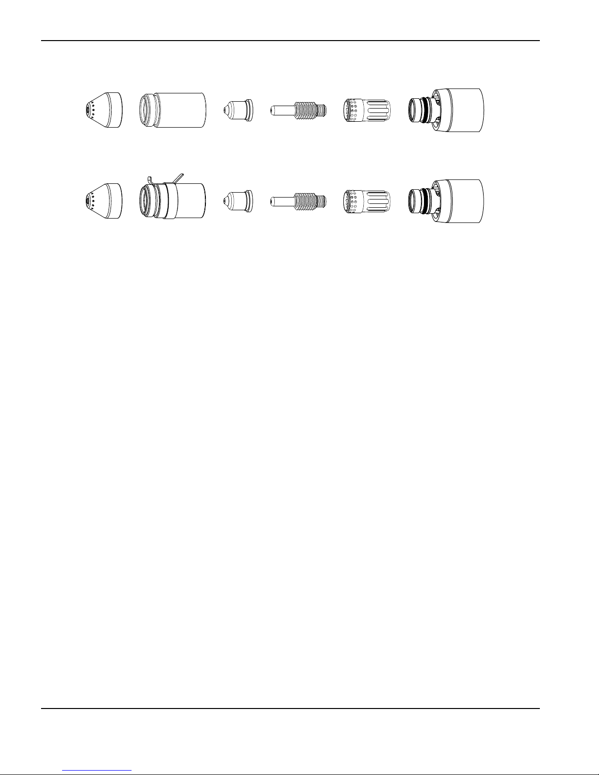
TORCH SETUP
65 A shielded consumables
6
5
A
220817
Shield
220817
Shield
220854
Retaining cap
220953
Ohmic-sensing
retaining cap
220819
Nozzle
6
5
A
220819
Nozzle
220842
Electrode
220842
Electrode
220857
Swirl ring
220857
Swirl ring
3-30 powermax
65/85
Service Manual
Page 79

TORCH SETUP
65A Shielded Air flow rate - slpm/scfh
Mild Steel
Metric
Material
Thickness
Torch-
to-Work
Distance
Initial Pierce
Height
Pierce
Delay
Time
Best Quality Settings Production Settings
Cut Speed Voltage Cut Speed Voltage
mm mm mm % seconds (mm/min) Volts (mm/min) Volts
2
0.1 6050 124 7000 121
3 0.2 5200 125 6100 123
4
6 2550 127 3240 127
8 1700 129 2230 128
1.5
10
12 1.2 850 134 1140 131
3.8 250
4.5 300
0.5
0.7 1100 131 1500 129
4250 125 5100 124
16 6.0 400 2.0 560 138 650 136
20
25 210 145 270 145
Edge Start
350 142 450 142
Hot 160 / 340
Cold 220 / 470
English
Material
Thickness
Torch-
to-Work
Distance
Initial Pierce
Height
Pierce
Delay
Time
Best Quality Settings Production Settings
Cut Speed Voltage Cut Speed Voltage
in in % seconds ipm Volts ipm Volts
16GA
10GA 190 125 224 123
3/16 in 0.2 140 126 168 125
0.15 250
0.1
260 123 294 121
1/4 in 0.5 90 127 116 127
3/8 in 0.7 45 130 62 129
1/2 in 0.18 300 1.2 30 135 40 132
0.06
5/8 in 0.24 400 2.0 23 138 26 136
3/4 in
7/8 in 12 143 14 143
Edge Start
15 141 19 141
1 in 8 145 10 145
powermax
65/85
Service Manual 3-31
Page 80

TORCH SETUP
65A Shielded Air flow rate - slpm/scfh
Stainless Steel
Metric
Material
Thickness
Torch-
to-Work
Distance
Initial Pierce
Height
Pierce
Delay Time
Best Quality Settings Production Settings
Cut Speed Voltage Cut Speed Voltage
mm mm mm % seconds (mm/min) Volts (mm/min) Volts
2
0.1 8100 125 10000 121
3 0.2 6700 125 8260 123
4
6 2450 126 2850 126
8
1.5
10
12 1.2 750 135 920 134
16
20 300 143 370 143
3.8 250
4.5 300
Edge Start
0.5
0.7
5200 125 6150 124
1500 129 1860 129
960 132 1250 132
500 139 500 139
Hot 160 / 340
Cold 220 / 470
English
Material
Thickness
Torch-
to-Work
Distance
Initial Pierce
Height
Pierce
Delay Time
Best Quality Settings Production Settings
Cut Speed Voltage Cut Speed Voltage
in in % seconds ipm Volts ipm Volts
16GA
10GA 240 125 296 123
3/16 in 0.2 155 126 168 125
1/4 in 0.5 80 126 96 126
3/8 in 0.7 40 131 52 131
0.06
0.15 250
0.1
345 124 426 121
1/2 in 0.18 300 1.2 26 136 32 135
5/8 in
3/4 in 14 142 15 142
Edge Start
20 139 20 139
3-32 powermax
65/85
Service Manual
Page 81

TORCH SETUP
65A Shielded Air flow rate - slpm/scfh
Aluminum
Metric
Material
Thickness
Torch-
to-Work
Distance
Initial Pierce
Height
Pierce Delay
Time
Best Quality Settings Production Settings
Cut Speed Voltage Cut Speed Voltage
mm mm mm % seconds (mm/min) Volts (mm/min) Volts
2
0.1 8800 121 10300 122
3 0.2 7400 124 8800 124
4
6 3200 130 4400 128
8
1.5
10
12 1.2 1000 138 1330 136
16
20 380 147 560 145
3.8 250
4.5 300
Edge Start
0.5
0.7
6000 126 7350 125
1950 133 2750 130
1200 136 1650 132
650 143 800 141
Hot 160 / 340
Cold 220 / 470
English
Material
Thickness
Torch-
to-Work
Distance
Initial Pierce
Height
Pierce Delay
Time
Best Quality Settings Production Settings
Cut Speed Voltage Cut Speed Voltage
in in % seconds ipm Volts ipm Volts
1/16 in
1/8 in 280 124 336 124
1/4 in 0.5 105 131 152 128
3/8 in 0.7 50 135 68 131
0.06
0.15 250
0.1
365 121 428 121
1/2 in 0.18 300 1.2 35 139 48 138
5/8 in
3/4 in 16 146 24 144
Edge Start
26 143 32 141
powermax
65/85
Service Manual 3-33
Page 82

TORCH SETUP
45 A shielded consumables
4
5
A
220817
Shield
220817
Shield
220854
Retaining cap
220953
Ohmic-sensing
retaining cap
220941
Nozzle
4
5
A
220941
Nozzle
220842
Electrode
220842
Electrode
220857
Swirl ring
220857
Swirl ring
3-34 powermax
65/85
Service Manual
Page 83

TORCH SETUP
45A Shielded Air flow rate - slpm/scfh
Mild Steel
Metric
Material
Thickness
Torch-
to-Work
Distance
Initial Pierce
Height
Pierce Delay
Time
Best Quality Settings Production Settings
Cut Speed Voltage Cut Speed Voltage
mm mm mm % seconds (mm/min) Volts (mm/min) Volts
0.5
1 9000 128 10800 128
0.0
9000 128 12500 126
1.5 0.1 9000 130 10200 129
2 0.3 6600 130 7800 129
3
4 2200 134 3560 131
1.5 3.8 250
0.4
3850 133 4900 131
6 0.5 1350 137 2050 132
English
Material
Thickness
Torch-
to-Work
Distance
Initial Pierce
Height
Pierce Delay
Time
Best Quality Settings Production Settings
Cut Speed Voltage Cut Speed Voltage
in in % seconds ipm Volts ipm Volts
26GA
22GA 350 128 450 128
18GA
0.02 0.08 400
16GA 350 130 400 129
14GA
12GA
10GA 100 134 164 131
0.06 0.15 250
0.0
0.1
0.2 270 130 320 129
0.4
350 128 500 128
350 129 400 128
190 133 216 131
3/16 in 0.5 70 135 108 132
1/4 in 0.6 48 137 73 132
Hot 150 / 310
Cold 210/ 450
powermax
65/85
Service Manual 3-35
Page 84

TORCH SETUP
45A Shielded Air flow rate - slpm/scfh
Stainless Steel
Metric
Material
Thickness
Torch-
to-Work
Distance
Initial Pierce
Height
Pierce
Delay Time
Best Quality Settings Production Settings
Cut Speed Voltage Cut Speed Voltage
mm mm mm % seconds (mm/min) Volts (mm/min) Volts
0.5
1 9000 130 10800 130
0.0
9000 130 12500 129
1.5 0.1 9000 130 10200 130
2 0.3 6000 132 8660 131
3
4 2000 134 2600 134
1.5 3.8 250
0.4
3100 132 4400 132
6 0.5 900 140 1020 139
English
Material
Thickness
Torch-
to-Work
Distance
Initial Pierce
Height
Pierce
Delay Time
Best Quality Settings Production Settings
Cut Speed Voltage Cut Speed Voltage
in in % seconds ipm Volts ipm Volts
26GA
22GA 350 130 450 129
18GA
0.02 0.08 400
16GA 350 130 400 130
14GA
12GA
10GA 100 133 134 134
0.06 0.15 250
0.0
0.1
0.2 250 132 360 131
0.4
350 130 500 129
350 130 400 130
140 132 206 131
3/16 in 0.5 52 135 58 135
1/4 in 0.6 30 141 35 140
Hot 150 / 310
Cold 210/ 450
3-36 powermax
65/85
Service Manual
Page 85

TORCH SETUP
45A Shielded Air flow rate - slpm/scfh
Aluminum
Metric
Material
Thickness
Torch-
to-Work
Distance
Initial Pierce
Height
Pierce
Delay Time
Best Quality Settings Production Settings
Cut Speed Voltage Cut Speed Voltage
mm mm mm % seconds (mm/min) Volts (mm/min) Volts
1
0.0 8250 136 11000 136
2 0.1 6600 136 9200 135
3 0.2 3100 139 6250 134
1.5 3.8 250
4 0.4 2200 141 4850 135
6 0.5 1500 142 2800 137
English
Material
Thickness
Torch-
to-Work
Distance
Initial Pierce
Height
Pierce
Delay Time
Best Quality Settings Production Settings
Cut Speed Voltage Cut Speed Voltage
in in % seconds ipm Volts ipm Volts
1/32 in
0.0 325 136 450 136
1/16 in 0.1 325 136 400 136
3/32 in 0.2 200 136 328 134
0.06 0.15 250
1/8 in 0.4 100 140 224 134
1/4 in 0.5 54 142 96 137
Hot 150 / 310
Cold 210/ 450
powermax
65/85
Service Manual 3-37
Page 86

TORCH SETUP
FineCut® consumables
Note: The cut charts in this section apply to both shielded and unshielded consumables.
220948
Shield
220955
Deflector
220953
Retaining cap
220854
Retaining cap
220930
Nozzle
220930
Nozzle
220842
Electrode
220842
Electrode
220857
Swirl ring
220857
Swirl ring
3-38 powermax
65/85
Service Manual
Page 87

TORCH SETUP
FineCut Air flow rate - slpm/scfh
Mild Steel
Metric
Material
Thickness
Amps
Torch-
to-Work
Distance
Initial Pierce Height
Pierce Delay
Time
Cut Speed Voltage
mm A mm mm % seconds (mm/min) Volts
0.5
0.6 8250 78
40
0.0
8250 78
0.8 0.1 8250 78
1
1.5
2 5250 82
45
1.5 3.8 250
0.2 8250 78
0.4
6400 78
3 0.5 2750 83
4 0.6 1900 84
Hot 155 / 330
Cold 215 / 460
Best Quality Settings
English
Material
Thickness
Amps
Torch-
to-Work
Distance
Initial Pierce Height
Pierce Delay
Time
Best Quality Settings
Cut Speed Voltage
A in in % seconds ipm Volts
26GA
24GA 325 78
22GA
40
20GA 325 78
18GA
0.06 0.15 250
16GA
14GA 220 82
45
12GA
10GA 95 84
0.0
0.1
0.2 325 78
0.4
0.5
325 78
325 78
250 78
120 83
powermax
65/85
Service Manual 3-39
Page 88

TORCH SETUP
FineCut Air flow rate - slpm/scfh
Stainless Steel
Metric
Material
Thickness
Amps
Torch-
to-Work
Distance
Initial Pierce Height
Pierce
Delay Time
Cut Speed Voltage
mm A mm mm % seconds (mm/min) Volts
0.5
0.6 8250 68
40
0.0
0.8 0.1 8250 68
1
1.5
2 4800 71
45
0.5 2.0 400
0.2 8250 68
0.4
3 0.5 2550 81
4 0.6 1050 84
Hot 155 / 330
Cold 215 / 460
Best Quality Settings
8250 68
6150 70
English
Material
Thickness
Amps
Torch-
to-Work
Distance
Initial Pierce Height
Pierce
Delay Time
Best Quality Settings
Cut Speed Voltage
A in in % seconds ipm Volts
26GA
24GA 325 68
22GA
40
20GA 325 68
18GA
0.02 0.08 400
16GA
14GA 200 70
45
0.0
0.1
0.2 325 68
0.4
325 68
325 68
240 70
12GA 0.5 120 80
10GA 0.6 75 83
3-40 powermax
65/85
Service Manual
Page 89

85 A unshielded consumables
TORCH SETUP
8
5
A
220955
Deflector
220854
Retaining cap
220816
Nozzle
220842
Electrode
220857
Swirl ring
powermax
65/85
Service Manual 3-41
Page 90

TORCH SETUP
85A Unshielded Air flow rate - slpm/scfh
Mild Steel
Metric
Material
Thickness
Torch-
to-Work
Distance
Initial Pierce
Height
Pierce
Delay Time
Best Quality Settings Production Settings
Cut Speed Voltage Cut Speed Voltage
mm mm mm % seconds (mm/min) Volts (mm/min) Volts
2
0.0 7150 117 10400 116
3 0.1 6240 118 9000 117
4 0.2 5250 118 7200 117
6
8 2400 121 3100 121
10 1560 123 2070 122
2.0
5.0 250
3450 120 4400 119
0.5
12 6.0 300 0.7 1200 126 1600 124
16
20 540 137 640 132
Edge Start
820 132 930 128
25 320 143 400 137
Hot 190 / 400
Cold 235 / 500
English
Material
Thickness
Torch-
to-Work
Distance
Initial Pierce
Height
Pierce
Delay Time
Best Quality Settings Production Settings
Cut Speed Voltage Cut Speed Voltage
in in % seconds ipm Volts ipm Volts
14GA
10GA
3/16 in 175 119 220 118
0.20 250
1/4 in
3/8 in 65 122 86 122
1/2 in 0.24 300 0.6 42 127 56 125
0.08
5/8 in
3/4 in 23 136 27 131
7/8 in 18 140 21 134
Edge Start
0.1 280 117 416 116
0.2
0.5
230 118 328 117
125 120 160 119
33 131 37 128
1 in 12 144 15 138
3-42 powermax
65/85
Service Manual
Page 91

TORCH SETUP
85A Unshielded Air flow rate - slpm/scfh
Stainless Steel
Metric
Material
Thickness
Torch-
to-Work
Distance
Initial Pierce
Height
Pierce Delay
Time
Best Quality Settings Production Settings
Cut Speed Voltage Cut Speed Voltage
mm mm mm % seconds (mm/min) Volts (mm/min) Volts
2
3 7000 118 9660 117
4 0.2 5600 118 7800 118
5.0 250
6
8 2250 121 2970 122
10
12 0.7 1000 129 1340 128
16
20 360 138 570 137
2.0
6.0 300
Edge Start
0.1
0.5
0.5 1430 123 1840 124
8550 117 11300 116
3400 120 4570 121
650 134 730 133
Hot 190 / 400
Cold 235 / 500
English
Material
Thickness
Torch-
to-Work
Distance
Initial Pierce
Height
Pierce Delay
Time
Best Quality Settings Production Settings
Cut Speed Voltage Cut Speed Voltage
in in % seconds ipm Volts ipm Volts
14GA
10GA
3/16 in 180 119 249 119
1/4 in
3/8 in 60 122 77 123
0.08
0.20 250
0.1 340 117 452 116
0.2
0.5
250 118 352 118
120 120 160 121
1/2 in 0.24 300 0.6 35 131 46 129
5/8 in
3/4 in 17 137 24 136
Edge Start
26 134 29 133
powermax
65/85
Service Manual 3-43
Page 92

TORCH SETUP
85A Unshielded Air flow rate - slpm/scfh
Aluminum
Metric
Material
Thickness
Torch-
to-Work
Distance
Initial Pierce
Height
Pierce
Delay Time
Best Quality Settings Production Settings
Cut Speed Voltage Cut Speed Voltage
mm mm mm % seconds (mm/min) Volts (mm/min) Volts
2
3 7350 120 9600 119
4 0.2 6000 122 8100 120
5.0 250
6
8 2350 127 3250 124
10
12 0.7 1300 133 1720 130
16
20 470 144 700 138
2.0
6.0 300
Edge Start
0.1
0.5
0.5 1800 128 2140 127
8700 118 11200 118
3300 125 4930 122
840 139 1130 134
Hot 190 / 400
Cold 235 / 500
English
Material
Thickness
Torch-
to-Work
Distance
Initial Pierce
Height
Pierce
Delay Time
Best Quality Settings Production Settings
Cut Speed Voltage Cut Speed Voltage
in in % seconds ipm Volts ipm Volts
1/8 in
3/16 in 200 123 271 120
1/4 in
3/8 in 75 127 88 126
0.08
0.20 250
0.2
0.5
280 120 368 119
110 126 172 122
1/2 in 0.24 300 0.6 45 135 62 131
5/8 in
3/4 in 22 143 32 137
Edge Start
34 139 45 134
3-44 powermax
65/85
Service Manual
Page 93

65 A unshielded consumables
TORCH SETUP
6
5
A
220955
Deflector
220854
Retaining cap
220819
Nozzle
220842
Electrode
220857
Swirl ring
powermax
65/85
Service Manual 3-45
Page 94

TORCH SETUP
65A Unshielded Air flow rate - slpm/scfh
Mild Steel
Metric
Material
Thickness
Torch-
to-Work
Distance
Initial Pierce
Height
Pierce Delay
Time
Best Quality Settings Production Settings
Cut Speed Voltage Cut Speed Voltage
mm mm mm % seconds (mm/min) Volts (mm/min) Volts
2
0.1 6050 117 7340 117
3 0.2 5200 118 6330 118
4
6 2550 120 3560 120
8 1620 123 2230 121
2.0
5.0 250
4250 118 5250 118
0.5
10 6.0 300 0.7 970 127 1500 122
12
16 500 134 650 129
Edge Start
760 129 1140 124
20 280 138 400 133
Hot 160 / 340
Cold 220 / 470
English
Material
Thickness
Torch-
to-Work
Distance
Initial Pierce
Height
Pierce Delay
Time
Best Quality Settings Production Settings
Cut Speed Voltage Cut Speed Voltage
in in % seconds ipm Volts ipm Volts
16GA
10GA 190 118 232 118
3/16 in 0.2 135 119 172 119
1/4 in 0.5 90 120 116 120
3/8 in 0.24 300 0.7 40 126 62 122
0.08
0.20 250
0.1
1/2 in
5/8 in 20 134 26 129
Edge Start
255 116 308 117
27 130 40 125
3/4 in 13 137 18 132
3-46 powermax
65/85
Service Manual
Page 95

TORCH SETUP
65A Unshielded Air flow rate - slpm/scfh
Stainless Steel
Metric
Material
Thickness
Torch-
to-Work
Distance
Initial Pierce
Height
Pierce
Delay Time
Best Quality Settings Production Settings
Cut Speed Voltage Cut Speed Voltage
mm mm mm % seconds (mm/min) Volts (mm/min) Volts
2
0.1 7950 117 10300 116
3 0.2 6600 118 8500 117
4
6 2300 121 3070 121
8 0.7 1400 123 1900 122
2.0
5.0 250
0.5
5050 119 6500 119
10 6.0 300 0.7 920 126 1250 123
12
16 430 135 500 133
Edge Start
710 130 925 127
Hot 160 / 340
Cold 220 / 470
English
Material
Thickness
Torch-
to-Work
Distance
Initial Pierce
Height
Pierce
Delay Time
Best Quality Settings Production Settings
Cut Speed Voltage Cut Speed Voltage
in in % seconds ipm Volts ipm Volts
16GA
10GA 235 118 304 118
3/16 in 0.2 150 120 194 120
1/4 in 0.5 75 121 100 121
0.08
0.20 250
0.1
340 116 437 115
3/8 in 0.24 300 0.7 38 125 52 122
1/2 in
5/8 in 17 135 20 133
Edge Start
25 132 32 129
powermax
65/85
Service Manual 3-47
Page 96

TORCH SETUP
65A Unshielded Air flow rate - slpm/scfh
Aluminum
Metric
Material
Thickness
Torch-
to-Work
Distance
Initial Pierce
Height
Pierce
Delay Time
Best Quality Settings Production Settings
Cut Speed Voltage Cut Speed Voltage
mm mm mm % seconds (mm/min) Volts (mm/min) Volts
2
0.1 7750 123 11300 122
3 0.2 6550 124 9500 123
4
6 3000 127 3900 126
8 0.7 1800 130 2460 127
2.0
5.0 250
0.5
5400 125 7640 124
10 6.0 300 0.7 1100 133 1640 129
12
16 600 139 700 136
Edge Start
900 135 1250 133
Hot 160 / 340
Cold 220 / 470
English
Material
Thickness
Torch-
to-Work
Distance
Initial Pierce
Height
Pierce
Delay Time
Best Quality Settings Production Settings
Cut Speed Voltage Cut Speed Voltage
in in % seconds ipm Volts ipm Volts
1/16 in
1/8 in 250 124 360 123
0.20 250
0.1
325 122 476 122
3/16 in 175 125 245 124
1/4 in 0.5 100 127 128 126
0.08
3/8 in 0.24 300 0.7 45 132 68 128
1/2 in
5/8 in 24 138 28 136
Edge Start
32 136 44 134
3-48 powermax
65/85
Service Manual
Page 97

45 A unshielded consumables
TORCH SETUP
4
5
A
220955
Deflector
220854
Retaining cap
220941
Nozzle
220842
Electrode
220857
Swirl ring
powermax
65/85
Service Manual 3-49
Page 98

TORCH SETUP
45A Unshielded Air flow rate - slpm/scfh
Mild Steel
Metric
Material
Thickness
Torch-
to-Work
Distance
Initial Pierce
Height
Pierce
Delay Time
Best Quality Settings Production Settings
Cut Speed Voltage Cut Speed Voltage
mm mm mm % seconds (mm/min) Volts (mm/min) Volts
0.5
1 9000 120 10800 121
0.0
9000 120 12500 120
1.5 0.1 7700 120 10200 121
2 0.3 6150 119 7800 122
3
4 2350 123 3560 124
1.5 3.8 250
0.4
3950 121 4900 123
6 0.5 1400 126 2050 124
English
Material
Thickness
Torch-
to-Work
Distance
Initial Pierce
Height
Pierce
Delay Time
Best Quality Settings Production Settings
Cut Speed Voltage Cut Speed Voltage
in in % seconds ipm Volts ipm Volts
26GA
22GA 350 120 450 120
18GA
16GA 300 121 400 121
14GA 0.2 250 119 320 122
0.06 0.15 250
12GA
10GA 100 123 164 124
0.0
0.1
0.4
350 120 500 120
350 119 400 121
200 120 216 123
3/16 in 0.5 85 122 108 124
1/4 in 0.6 48 127 73 124
Hot 147 / 310
Cold 210 / 450
3-50 powermax
65/85
Service Manual
Page 99

TORCH SETUP
45A Unshielded Air flow rate - slpm/scfh
Stainless Steel
Metric
Material
Thickness
Torch-
to-Work
Distance
Initial Pierce
Height
Pierce Delay
Time
Best Quality Settings Production Settings
Cut Speed Voltage Cut Speed Voltage
mm mm mm % seconds (mm/min) Volts (mm/min) Volts
0.5
1 9000 121 10800 119
0.0
9000 121 12500 119
1.5 0.1 9000 121 10200 120
2 0.3 6000 122 9600 120
3
4 1900 128 3000 122
1.5 3.8 250
0.4
3250 123 4750 120
6 0.5 700 130 1450 124
English
Material
Thickness
Torch-
to-Work
Distance
Initial Pierce
Height
Pierce Delay
Time
Best Quality Settings Production Settings
Cut Speed Voltage Cut Speed Voltage
in in % seconds ipm Volts ipm Volts
26GA
22GA 350 120 450 119
18GA
0.02 0.08 400
16GA 350 121 400 120
14GA
12GA
10GA 100 125 140 121
0.06 0.15 250
0.0
0.1
0.2 300 122 400 120
0.4
350 120 500 119
350 118 400 119
150 121 224 120
3/16 in 0.5 42 131 88 123
1/4 in 0.6 25 130 48 124
Hot 147 / 310
Cold 210 / 450
powermax
65/85
Service Manual 3-51
Page 100

TORCH SETUP
45A Unshielded Air flow rate - slpm/scfh
Aluminum
Metric
Material
Thickness
Torch-
to-Work
Distance
Initial Pierce
Height
Pierce
Delay Time
Best Quality Settings Production Settings
Cut Speed Voltage Cut Speed Voltage
mm mm mm % seconds (mm/min) Volts (mm/min) Volts
1
0.0 7400 126 11000 121
2 0.1 4400 127 9200 123
3 0.2 2800 129 6250 125
1.5 3.8 250
4 0.4 2100 132 4700 126
6 0.5 1050 135 2250 127
English
Material
Thickness
Torchto-Work
Distance
Initial Pierce
Height
Pierce
Delay Time
Best Quality Settings Production Settings
Cut Speed Voltage Cut Speed Voltage
in in % seconds ipm Volts ipm Volts
1/32 in
0.0 325 126 450 121
1/16 in 0.1 200 126 400 122
3/32 in 0.2 150 127 328 124
0.06 0.15 250
1/8 in 0.4 100 130 224 125
1/4 in 0.5 36 136 72 127
Hot 147 / 310
Cold 210 / 450
3-52 powermax
65/85
Service Manual
 Loading...