

Page 1
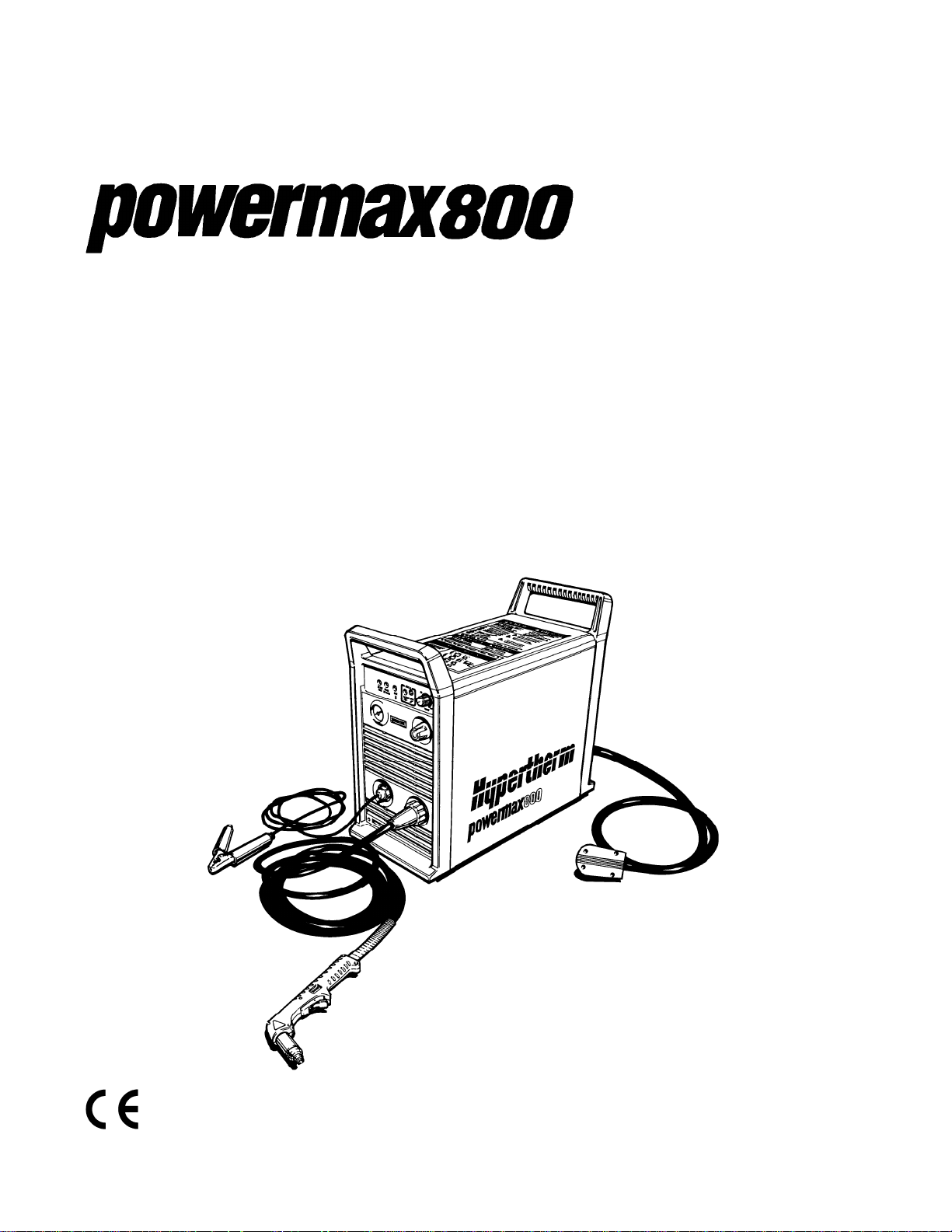
Plasma Arc
Cutting System
Service Manual
802280 - Revision 4
®
EN50199
EN50192
Page 2

Plasma Arc Cutting System
Service Manual
IM-228
(P/N 802280)
for systems beginning with serial number
800-010000
Revision 4 December, 1997
Hypertherm, Inc.
P.O. Box 5010
Hanover, New Hampshire 03755-5010
Tel.: (603) 643-3441
Fax: (603) 643-5352
© Copyright 1997 Hypertherm, Inc.
All Rights Reserved
HYPERTHERM and POWERMAX are trademarks of Hypertherm, Inc. and may be
registered in the United States and/or other countries
Page 3

Hypertherm Offices Worldwide
Hypertherm, Inc.
Etna Road, P.O. Box 5010
Hanover, NH 03755 USA
Tel.: (603) 643-3441 (Main Office)
Fax: (603) 643-5352 (All Departments)
Tel.: (800) 643-9878 (Technical Service)
Tel.: (800) 737-2978 (Customer Service)
Hypertherm Plasmatechnik GmbH
Ohmstrasse 6
D–63477 Maintal, Germany
Tel.: 49 6181 94070
Fax: 49 6181 940719
European Technical Support Organization (ETSO)
Ohmstrasse 6
D–63477 Maintal, Germany
Tel.: 49 6181 94070
Fax: 49 6181 940739
Hypertherm Singapore Pte Ltd
No. 19 Kaki Bukit Road 2
K.B. Warehouse Complex
Singapore 417847, Republic of Singapore
Tel.: 65 841 2489
Fax: 65 841 2490
:
Hypertherm U.K.
9 Berkeley Court • Manor Park
Runcorn, Cheshire, England WA7 1TQ
Tel.: 44 1928 579 074
Fax: 44 1928 579 604
Hypertherm France
10, Allée de I’lsara
F-95000 Cergy-Pontoise, France
Tel.: 33 1 34 24 03 05
Fax: 33 1 34 25 09 64
Hypertherm Italy
Via Stilicone 18
20154 Milan, Italy
Tel.: 39 2 34 53 22 11
Fax: 39 2 34 53 20 18
Page 4

ELECTROMAGNETIC COMPATIBILITY
EMC INTRODUCTION
The 400V CE power supply has been built
in compliance with standard EN50199. To
ensure that the equipment works in a
compatible manner with other radio and
electronic systems, the equipment should
be installed and used in accordance with
the information below to achieve
electromagnetic compatibility.
The limits required by EN50199 may not
be adequate to completely eliminate
interference when the affected equipment
is in close proximity or has a high degree
of sensitivity. In such cases it may be
necessary to use other measures to
further reduce interference.
This plasma equipment should be used
only in an industrial environment. It may
be difficult to ensure electromagnetic
compatibility in a domestic environment.
INSTALLATION AND USE
The user is responsible for installing and
using the plasma equipment according to
the manufacturer's instructions. If
electromagnetic disturbances are
detected then it shall be the responsibility
of the user to resolve the situation with the
technical assistance of the manufacturer.
In some cases this remedial action may be
as simple as earthing the cutting circuit,
see
Earthing of Workpiece
it could involve constructing an
electromagnetic screen enclosing the
power source and the work complete with
associated input filters. In all cases
electromagnetic disturbances must be
reduced to the point where they are no
longer troublesome.
ASSESSMENT OF AREA
Before installing the equipment the user
shall make an assessment of potential
electromagnetic problems in the
surrounding area. The following shall be
taken into account:
a. Other supply cables, control cables,
signalling and telephone cables; above,
below and adjacent to the cutting
equipment.
b. Radio and television transmitters and
receivers.
c. Computer and other control equipment.
d. Safety critical equipment, for example
guarding of industrial equipment.
e. Health of the people around, for
example the use of pacemakers and
hearing aids.
. In other cases
f. Equipment used for calibration or
measurement.
g. Immunity of other equipment in the
environment. User shall ensure that other
equipment being used in the environment
is compatible. This may require additional
protection measures.
h. Time of day that cutting or other
activities are to be carried out.
The size of the surrounding area to be
considered will depend on the structure of
the building and other activities that are
taking place. The surrounding area may
extend beyond the boundaries of the
premises.
METHODS OF REDUCING
EMISSIONS
Mains Supply
Cutting equipment should be connected
to the mains supply according to the
manufacturer's recommendations. If
interference occurs, it may be necessary
to take additional precautions such as
filtering of the mains supply.
Consideration should be given to
shielding the supply cable of permanently
installed cutting equipment, in metallic
conduit or equivalent. Shielding should be
electrically continuous throughout its
length. The shielding should be
connected to the cutting mains supply so
that good electrical contact is maintained
between the conduit and the cutting power
source enclosure
Maintenance of Cutting Equipment
The cutting equipment should be routinely
maintained according to the
manufacturer's recommendations. All
access and service doors and covers
should be closed and properly fastened
when the cutting equipment is in
operation. The cutting equipment should
not be modified in any way except for
those changes and adjustments covered
in the manufacturer's instructions. In
particular, the spark gaps of arc striking
and stabilizing devices should be adjusted
and maintained according to the
manufacturer's recommendations.
Cutting Cables
The cutting cables should be kept as short
as possible and should be positioned
close together, running at or close to the
floor level.
Equipotential Bonding
Bonding of all metallic components in the
cutting installation and adjacent to it
should be considered. However, metallic
components bonded to the workpiece will
increase the risk that the operator could
receive a shock by touching these metallic
components and the electrode at the
same time. The operator should be
insulated from all such bonded metallic
components.
Earthing of Workpiece
Where the workpiece is not bonded to
earth for electrical safety, nor connected
to earth because of its size and position,
for example, ship's hull or building
steelwork, a connection bonding the
workpiece to earth may reduce emissions
in some, but not all instances. Care should
be taken to prevent the earthing of the
workpiece increasing the risk of injury to
users, or damage to other electrical
equipment. Where necessary, the
connection of the workpiece to earth
should be made by a direct connection to
the workpiece, but in some countries
where direct connection is not permitted,
the bonding should be achieved by
suitable capacitances selected according
to national regulations.
Note. The cutting circuit may or may not be
earthed for safety reasons. Changing the
earthing arrangements should only be
authorized by a person who is competent
to assess whether the changes will
increase the risk of injury, for example, by
allowing parallel cutting current return
paths which may damage the earth
circuits of other equipment. Further
guidance is given in IEC TC26 (sec)94
and IEC TC26/108A/CD Arc Welding
Equipment Installation and Use.
Screening and Shielding
Selective screening and shielding of other
cables and equipment in the surrounding
area may alleviate problems of
interference. Screening of the entire
plasma cutting installation may be
considered for special applications.
Service Manual
i
Page 5

WARRANTY
WARNING
Genuine Hypertherm parts are the factory-recommended replacement parts for
your Hypertherm system. Any damage caused by the use of other than genuine
Hypertherm parts may not be covered by the Hypertherm warranty.
GENERAL
HYPERTHERM, Inc. warrants that Products shall be free from defects in materials and workmanship,
under proper and normal use for which such Equipment is recommended, for a period of two (2)
years, except only with respect to the Torch, for which the warranty period shall be one (1) year, from
the date of its delivery to you.
HYPERTHERM, at its sole option, shall repair, replace, or adjust, free of charge, any Products
covered by this warranty which shall be returned with HYPERTHERM's prior authorization (which
shall not be unreasonably withheld), properly packed, to HYPERTHERM's place of business in
Hanover, New Hampshire, all costs, insurance and freight prepaid, and which examination proves not
to be free from defects in materials and workmanship. HYPERTHERM shall not be liable for any
repairs, replacements, or adjustments of Products covered by this warranty, except those made
pursuant to this paragraph or with HYPERTHERM's written consent. This warranty shall not apply to
any Product which has been mishandled, incorrectly installed, modified or assembled by you or any
other person. HYPERTHERM shall be liable for breach of this warranty only if it receives written
notice of such breach within the applicable warranty period specified herein above. THE FOREGOING SHALL CONSTITUTE THE SOLE REMEDY TO DISTRIBUTORS OR THEIR CUSTOMERS
FOR ANY BREACH BY HYPERTHERM OF ITS WARRANTY.
PATENT INDEMNITY
Except only in cases of Products not manufactured by HYPERTHERM or manufactured by a person
other than HYPERTHERM not in strict conformity with HYPERTHERM's specifications, and in cases
of designs, processes, formulae or combinations not developed or purported to be developed by
HYPERTHERM, HYPERTHERM agrees to indemnify, protect and hold harmless Distributors and
their customers against any and all liability or claims in any manner imposed upon or accruing against
Distributors and their customers because of the use in or about the construction or operation of
Equipment or any design, system, formula, combination, article or material which infringes or alleges
to infringe on any patent or other right. Distributors shall notify HYPERTHERM promptly upon learning
of any action or threatened action in connection with any such alleged infringement, and each party
may appoint its own counsel for any such action or threatened action.
DISCLAIMER OF OTHER WARRANTIES
HYPERTHERM MAKES NO WARRANTIES REGARDING PRODUCTS MANUFACTURED BY IT OR
OTHERS (INCLUDING WITHOUT IMPLIED LIMITATION WARRANTIES AS TO MERCHANTABILITY
OR FITNESS FOR A PARTICULAR PURPOSE), EITHER EXPRESS OR IMPLIED, EXCEPT AS
PROVIDED HEREIN. This warranty is in lieu of any and all warranties, express or implied, by law or
otherwise; and Distributors are not authorized to give any other warranty purporting to be binding
upon HYPERTHERM upon resale of Products to their customers. IN NO EVENT shall HYPERTHERM be liable for incidental or consequential damages or injury to the person or property of
anyone by reason of any defect in any Equipment sold hereunder.
ii
Service Manual
Page 6

TABLE OF CONTENTS
SECTION 1 SAFETY ......................................................................................................................1-1
About Notes, Cautions & Warnings .................................................................................................................... 1-2
Safety Instructions .............................................................................................................................................. 1-2
Eye Protection ............................................................................................................................................. 1-2
Skin Protection ............................................................................................................................................. 1-2
Toxic Fume Prevention .................................................................................................................................1-2
Fire Prevention ............................................................................................................................................. 1-2
Electric Shock Prevention ............................................................................................................................ 1-2
Explosion Prevention ................................................................................................................................... 1-3
Noise Prevention .......................................................................................................................................... 1-4
Grounding ..................................................................................................................................................... 1-4
Safety Reminders ......................................................................................................................................... 1-4
Electronic Health Support Equipment ...........................................................................................................1-4
SECTION 1A SÉCURITÉ.............................................................................................................. 1a-1
Au sujet des Notes, Attention et avertissement ............................................................................................... 1a-1
Consignes de sécurité ..................................................................................................................................... 1a-2
Protection des yeux .................................................................................................................................. 1a-2
Protection de la peau ................................................................................................................................ 1a-2
Prévention des vapeurs toxiques .............................................................................................................. 1a-2
Prévention des incendies .......................................................................................................................... 1a-2
Prévention des chocs électriques ............................................................................................................. 1a-2
Prévention des explosions ........................................................................................................................ 1a-3
Protection contre le bruit ........................................................................................................................... 1a-4
Mise à la masse et à la terre ..................................................................................................................... 1a-4
Rappels de sécurité .................................................................................................................................. 1a-4
Prothèses électroniques ........................................................................................................................... 1a-4
SECTION 2 DESCRIPTION & SPECIFICATIONS ....................................................................... 2-1
Introduction .......................................................................................................................................................... 2-2
Specifications .......................................................................................................................................................2-3
PAC121 50A Torches .......................................................................................................................................... 2-4
IEC Symbols Used ...............................................................................................................................................2-6
SECTION 3 MAINTENANCE........................................................................................................ 3-1
Introduction .......................................................................................................................................................... 3-2
Routine Maintenance ........................................................................................................................................... 3-2
Theory of Operation ............................................................................................................................................. 3-4
Sequence of Operation ........................................................................................................................................ 3-6
Troubleshooting ................................................................................................................................................... 3-7
Power Board ...................................................................................................................................................... 3-26
Control Board .....................................................................................................................................................3-28
Torch Check ....................................................................................................................................................... 3-30
PAC121TS Torch Parts Removal and Replacement ......................................................................................... 3-32
PAC121MS Torch Parts Removal and Replacement ........................................................................................ 3-34
Quick Disconnect O-Ring Removal and Replacement ...................................................................................... 3-36
SECTION 4 PARTS LIST ............................................................................................................. 4-1
Power Supply - 208/240/480V
200/230/400V ............................................................................................................................. 4-2
PAC121TS Torch Assembly .............................................................................................................................. 4-10
PAC121MS Torch Assembly ............................................................................................................................. 4-11
Consumable Parts ............................................................................................................................................. 4-12
Powermax800 Field Upgrade Kits and Optional Parts ....................................................................................... 4-13
Power Supplies - 208/240/480V ........................................................................................................................ 4-13
Power Supplies - 200/230/400V ........................................................................................................................ 4-13
Recommended Spare Parts - Powermax800 - 208/240/480V ...........................................................................4-14
Recommended Spare Parts - Powermax800 - 200/230/400V ...........................................................................4-14
Service Manual
iii
10-96
Page 7

TABLE OF CONTENTS
SECTION 5 PARTS LIST - CE .....................................................................................................5-1
Power Supply - 400V CE ..................................................................................................................................... 5-2
PAC121TS Torch Assembly .............................................................................................................................. 5-10
PAC121MS Torch Assembly ............................................................................................................................. 5-11
Consumable Parts - CE ..................................................................................................................................... 5-12
Powermax800 Field Upgrade Kits and Optional Parts ....................................................................................... 5-13
Power Supplies - 400V CE ................................................................................................................................ 5-13
Recommended Spare Parts - Powermax800 - 400V CE ...................................................................................5-14
SECTION 6 WIRING DIAGRAMS ................................................................................................ 6-1
Powermax800 Electrical Schematic: 208/240/480V ............................................................................................ 6-2
Powermax800 Electrical Schematic: 200/230/400V ............................................................................................ 6-3
Powermax800 Electrical Schematic: 400V CE .................................................................................................... 6-4
Powermax800 Troubleshooting Schematic 1 of 2 ............................................................................................... 6-5
Powermax800 Troubleshooting Schematic 2 of 2 ............................................................................................... 6-6
Powermax800 CE Troubleshooting Schematic 1 of 2 ......................................................................................... 6-7
Powermax800 CE Troubleshooting Schematic 2 of 2 ......................................................................................... 6-8
APPENDIX A AERATION MANIFOLD FOR CUTTING ALUMINUM ............................................ a-1
APPENDIX B STANDARDS INDEX............................................................................................... a-2
ILLUSTRATIONS
Figure 2-1 Powermax800 Hand Plasma Cutting System ................................................................................ 2-2
Figure 2-2 Powermax800 Power Supply with Dimensions .............................................................................. 2-3
Figure 2-3 PAC121TS Torch with Dimensions ................................................................................................ 2-4
Figure 2-4 PAC121MS Torch with Dimensions ............................................................................................... 2-4
Figure 2-5 S Mark Label ................................................................................................................................. 2-5
Figure 3-1 Filter Assembly ............................................................................................................................... 3-2
Figure 3-2 Air Filter Removal ........................................................................................................................... 3-3
Figure 3-3 Inverter Links .................................................................................................................................. 3-4
Figure 3-4 Single-Phase, 240 or 208V Block Diagram .................................................................................... 3-5
Figure 3-5 Back Side of Power Board - Test Points ...................................................................................... 3-27
Figure 3-6 Control Board Test Points ............................................................................................................ 3-29
Figure 3-7 PAC121TS Torch Main Body Removal ........................................................................................ 3-32
Figure 3-8 PAC121TS Torch Switch Removal .............................................................................................. 3-33
Figure 3-9 PAC121MS Torch Assembly ........................................................................................................ 3-35
Figure 3-10 Quick Disconnect O-Ring Removal and Replacement ................................................................. 3-36
Figure 4-1 Powermax800 - Front ..................................................................................................................... 4-3
Figure 4-2 Powermax800 - Top and Right Side .............................................................................................. 4-5
Figure 4-3 Powermax800 - Bottom and Left Side ............................................................................................ 4-7
Figure 4-4 Powermax800 - Rear ..................................................................................................................... 4-9
Figure 4-5 PAC121TS Torch Assembly and Leads ....................................................................................... 4-10
Figure 4-6 PAC121MS Torch Assembly and Leads ...................................................................................... 4-11
Figure 4-7 Consumable Parts ........................................................................................................................4-12
Figure 5-1 Powermax800 CE - Front ............................................................................................................... 5-3
Figure 5-2 Powermax800 CE - Top and Right Side ........................................................................................ 5-5
Figure 5-3 Powermax800 CE - Bottom and Left Side ...................................................................................... 5-7
Figure 5-4 Powermax800 CE - Rear ............................................................................................................... 5-9
Figure 5-5 PAC121TS Torch Assembly and Leads ....................................................................................... 5-10
Figure 5-6 PAC121MS Torch Assembly and Leads ...................................................................................... 5-11
Figure 5-7 Consumable Parts - CE ................................................................................................................ 5-12
Figure a-1 Aeration Manifold ........................................................................................................................... a-1
iv
9-96
Service Manual
Page 8
Section 1 SAFETY
In this section:
SAFETY
About Notes< Cautions and Warnings .................... 1-1
Safety Instructions................................................... 1-2
Eye Protection .................................................. 1-2
Skin Protection ................................................. 1-2
Toxic Fume Prevention ..................................... 1-2
Fire Prevention ................................................. 1-2
Electric Shock Prevention................................. 1-2
Explosion Prevention ........................................ 1-3
Compressed Gas Cylinders .......................... 1-3
Pressure Regulators...................................... 1-3
Hoses ............................................................ 1-3
Noise Protection .................................................. 1-4
Grounding ............................................................ 1-4
Input Power ................................................... 1-4
Work Cable.................................................... 1-4
Work Table .................................................... 1-4
Safety Reminders ................................................ 1-4
Electronic Health Support Equipment .................. 1-4
Before using this plasma arc system. . . .
Each person who will operate this equipment, perform
service or maintenance, or supervise its use must read
the safety instructions and warnings in this manual and
the labels on the equipment.
About Notes, Cautions and Warnings
Notes: Throughout this manual, useful information for operating the plasma system is presented in “notes”,
such as shown in this paragraph.
Cautions: Information in bold type and surrounded by a box describes a situation that may cause
damage to the plasma system.
WARNINGS
Warnings describe situations that present a physical danger to the operator, and advice to avoid or
correct the situation. Each type of warning includes applicable danger symbols, such as a hand burn,
electrical shock, fire, explosion, etc.
WARNING — Instant-On
Torches
Instant-on torches produce a plasma
arc immediately after the torch switch
is
pushed.
Always hold a hand torch away from
your body as a precaution against
accidental torch firing. Be aware of
this hazard, which has potential for
serious bodily injury.
• Never touch the torch body, workpiece or the water in
a water table when operating the plasma system.
• When using a water table, be sure that it is correctly
connected to earth ground.
• Operating the plasma system completes an electrical
circuit between the torch and the workpiece and
anything touching the workpiece. The workpiece is part
of the electrical circuit.
WARNING — Electric Shock
HYPERTHERM Plasma Systems
1-1
10/24/96
Page 9

SAFETY
Eye Protection
• Wear dark safety glasses or goggles with side
shields, or a welding helmet, in accordance with
applicable national or local codes, to protect eyes
against the plasma arc’s ultraviolet and infrared rays.
Lens Shade
Arc Current AWS (USA) ISO-4850
Up to 100 A No. 8 No. 11
100–200 A No. 10 No. 11-12
200–400 A No. 12 No. 13
Over 400 A No. 14 No. 14
• Replace the glasses, goggles or helmet when the lens
becomes pitted or broken.
• Warn other people in the area not to look directly at
the arc unless they are wearing glasses, goggles or a
helmet.
• Prepare the cutting area in a manner that reduces the
reflection and transmission of ultraviolet light:
– Paint walls and other surfaces with dark colors to
reduce reflection.
– Install protective screens or curtains to reduce
ultraviolet transmission.
Skin Protection
• Wear protective clothing to protect against burns
caused by ultraviolet light, sparks and hot metal:
– Gauntlet gloves, safety shoes and hat.
– Flame-retardant clothing which covers all
exposed areas.
– Cuffless trousers to prevent entry of sparks and
slag.
Toxic Fume Prevention
• Keep the cutting area well ventilated.
• Remove all chlorinated solvents from the cutting area
before cutting. Certain chlorinated solvents
decompose when exposed to ultraviolet radiation to
form phosgene gas.
• Wear proper breathing mask and use proper
ventilation when cutting galvanized metal.
• Do not cut containers with toxic materials inside.
Clean containers that have held toxic materials
thoroughly before cutting.
WARNING — Toxic Fumes
Do not cut metal or painted metals
containing zinc, lead, cadmium or beryllium
unless the operator, or anyone else subjected
to the fumes, wears respiratory equipment or
an air-supplied helmet.
Fire Prevention
• Make fire extinguishers available in the
cutting area.
• Remove all combustible materials from the immediate
cutting area to a distance of at least 35 feet (10 m).
• Quench freshly cut metal or allow metal to cool
before handling it or bringing it into contact with
combustible materials.
• Never use a plasma system to cut containers with
potentially flammable materials inside. Such
containers must be thoroughly cleaned prior to
cutting.
• Ventilate potentially flammable atmospheres before
cutting with a plasma system. When cutting with
oxygen as the plasma gas, an exhaust ventilation
system is required.
• Never operate the plasma system in an atmosphere
which contains heavy concentrations of dust,
flammable gas or combustible liquid vapors unless
properly vented.
Electric Shock Prevention
All Hypertherm plasma systems use high
voltage (up to 280 VDC) to initiate the plasma
arc. Take the following precautions when
operating the plasma system:
• Wear insulated gloves and boots, and keep body and
clothing dry.
• Do not stand, sit or lie on—or touch—any wet surface
when using the plasma system.
• Maintain proper insulation against electrical shock. If
you must work in or near a damp area, use extreme
caution.
• Provide a wall-mounted disconnect switch with
properly sized fuses close to the power supply. This
switch allows the operator to turn the power supply off
quickly in an emergency situation.
• Conform to all local electrical codes for primary wiring
sizes and types.
• Inspect the primary power cord frequently for damage
or cracking of the cover. Bare wiring can kill. Do not
use a system with a damaged power cord. Replace a
damaged power cord immediately.
• Inspect the torch leads. Replace if frayed or
damaged.
• Do not pick up the workpiece, including the waste
cutoff, while you cut. Leave the workpiece in place or
on the workbench with the work cable attached during
the cutting process.
1-2
01/97
HYPERTHERM Plasma Systems
Page 10
SAFETY
Electric Shock Prevention (continued)
• Before changing the torch parts, disconnect the main
power or unplug the power supply. After changing
torch parts and replacing the retaining cap, plug in the
power supply again.
• Never bypass or shortcut the safety interlocks.
• Before removing a power supply cover for
maintenance, disconnect the main power at the wall
disconnect switch or unplug the power supply. To
avoid exposure to severe electrical hazard, wait five
minutes after disconnecting the main power to allow
capacitors to discharge.
• Never operate the plasma system unless the power
supply unit covers are in place. Exposed power
supply connections present a severe electrical
hazard.
Explosion Prevention
WARNING — Compressed Gas
The plasma system uses compressed gas.
Observe proper precautions when handling and
using compressed gas equipment and cylinders.
• Never use a cylinder that is not upright and secured
in place.
• Never move or transport a cylinder without its
protective valve cover in place.
• Never use a gas cylinder or its contents for any
purpose other than that for which it is intended.
• Never lubricate cylinder valves with oil or grease.
• Never allow electrical contact between the plasma arc
and a cylinder.
• Never expose cylinders to excessive heat, sparks,
slag or open flame.
• Never use hammers, wrenches or other tools to open
stuck cylinder valves.
Pressure Regulators
• Be certain that all pressure regulators are in proper
working condition.
• Never use a regulator for any gas other than that for
which it is intended.
• Never use a regulator that leaks, creeps excessively
or is physically damaged in any way.
• Never attempt to lubricate a regulator with oil or
grease.
• Do not use the plasma system if explosive dust or
vapors may be present.
• Do not cut pressurized cylinders or any closed
container.
WARNING —
Hydrogen Explosion Hazard
If your system uses hydrogen, remember that this
is a flammable gas that presents an explosion
hazard. Keep flames away from cylinders
containing hydrogen mixtures and hoses that
carry hydrogen mixtures. Also, keep flames and
sparks away from the torch when using argonhydrogen as the plasma gas.
Compressed Gas Cylinders
Handle and use compressed gas cylinders in accordance with safety standards published by the U.S.
Compressed Gas Association (CGA), American Welding Society (AWS), Canadian Standards Association
(CSA) or applicable national or local codes.
• Never use a cylinder that leaks or is physically
damaged.
WARNING — Hydrogen Detonation
with Aluminum Cutting
When cutting aluminum underwater, or with the
water touching the underside of the aluminum,
free hydrogen gas may collect under the
workpiece and detonate during plasma cutting
operations.
Installing an aeration manifold on the floor of the
water table is an effective way to eliminate the
possibility of hydrogen detonation when cutting
aluminum. Refer to the Appendix section of this
manual for instructions on how to fabricate an
aeration manifold.
Hoses
• Label and color-code all gas hoses in order to clearly
identify the type of gas in each hose. Consult
applicable national or local codes.
• Never use the oxygen hose for any gas other than
oxygen.
• Examine hoses at regular intervals for leaks, wear,
loose connections or other hazard.
• Replace hose that is damaged in any way.
HYPERTHERM Plasma Systems
1-3
10/24/96
Page 11

SAFETY
Hoses (continued)
• Keep hose lengths to a minimum to prevent damage,
reduce pressure drop and to prevent possible flow
restrictions.
• Prevent kinking by laying out hoses as straight as
possible between termination points.
• Coil any excess hose and place it out of the way to
prevent damage and to eliminate the danger of
tripping.
Noise Protection
The plasma cutting process can generate high
levels of noise. Depending on the arc current,
material being cut, acoustics and size of the
cutting room, distance from the torch and other factors,
acceptable noise levels as defined by national or local
codes may be exceeded by your plasma system.
• Always wear proper ear protection when cutting or
gouging with the plasma system.
Grounding
Input Power
• Be sure to connect the power cord ground wire to the
ground in the disconnect box.
• If installation of the plasma system involves
connecting the power cord to the power supply, be
sure to properly connect the power cord ground wire.
Conform to Canadian Standards Association (CSA)
standards by placing the power cord ground wire on
the stud first; then place any other ground wires on
top of the power cord ground. Fasten the retaining
nut tightly.
• Tighten all electrical connections to avoid excessive
heating.
Work Cable
• Attach the work cable securely to the workpiece or
the work table by making good metal-to-metal
contact.
Do not connect it to the piece that will fall away when
the cut is complete.
Work Table
• Connect the work table to a high-quality earth
ground, in accordance with the U.S. National
Electrical Code, Article 250, Section H, Grounding
Electrode System, or other appropriate national or
local codes.
Safety Reminders
• Never bypass or shortcut the safety interlocks on any
of the plasma system units.
• Except in Hypertherm’s largest mechanized systems,
all Hypertherm torches are designed with a safety
interlock that prevents firing of the plasma arc when
the retaining cap is loosened.
• Each Hypertherm plasma system is designed to be
used only with specific Hypertherm torches. Do not
substitute other torches which could overheat and
present a potentially dangerous situation to the
operator and any personnel in the area. Hypertherm’s
warranty does not cover problems caused by the use
of torches not made by Hypertherm.
• Use only consumable parts and replacement parts
made by Hypertherm. Hypertherm’s warranty does
not cover problems caused by the use of parts not
made by Hypertherm.
• Never operate the plasma system with any of its
covers not in place. This would be hazardous to the
operator and other people in the area, and prevents
the proper cooling of the equipment.
Electronic Health Support Equipment
Plasma arc cutting and gouging systems create electric
and magnetic fields that may interfere with the correct
operation of electronic health support equipment, such
as pacemakers or hearing aids. Any person who wears
a pacemaker or hearing aid should consult a doctor
before operating or being near any plasma system
when it is in use. To minimize exposure to EMF:
• Keep both the work cable and the torch lead on one
side of your body. Keep your body from coming in
between the torch lead and the work cable.
• Route torch leads as close as possible to work cable.
• Do not wrap the torch lead or work cable around your
body.
• Stay as far away from the power supply as possible.
1-4
10/24/96
HYPERTHERM Plasma Systems
Page 12
Section 1a SÉCURITÉ
SÉCURITÉ
IDENTIFIER LES CONSIGNES
DE SÉCURITÉ
Les symboles indiqués dans cette section sont utilisés pour
identifier les risques éventuels. Si vous trouvez un symbole
de sécurité, que ce soit dans ce manuel ou sur
l’équipement, soyez conscient des risques de blessures et
suivez les instructions correspondantes afin d’éviter ces
risques.
SUIVRE LES INSTRUCTIONS
DE SÉCURITÉ
Lire attentivement toutes les consignes de sécurité dans le
présent manuel et sur les étiquettes de sécurité se trouvant
sur la machine.
• Les étiquettes de sécurité doivent rester lisibles.
Remplacer immédiatement les étiquettes manquantes ou
abîmées.
• Apprendre à faire fonctionner la machine et à utiliser
correctement les commandes. Ne laisser personne utiliser
la machine sans connaître son fonctionnement.
• Garder la machine en bon état. Des modifications non
autorisées sur la machine peuvent engendrer des
problèmes de sécurité et raccourcir la durée d’utilisation
de l’équipement.
DANGER AVERTISSEMENT PRÉCAUTION
Les signaux DANGER ou AVERTISSEMENT sont utilisés
avec un symbole de sécurité, DANGER correspondant aux
risques les plus sérieux.
• Les étiquettes de sécurité DANGER et AVERTISSEMENT sont situées sur la machine pour signaler certains
dangers spécifiques.
• Les messages d’AVERTISSEMENT précèdent les
instructions d’utilisation expliquées dans ce manuel et
signalent les risques de blessures ou de mort au cas où
ces instructions ne seraient pas suivies correctement.
• Les messages de PRÉCAUTION précèdent les
instructions d’utilisation contenues dans ce manuel et
signalent que le matériel risque d’être endommagé si les
instructions ne sont pas suivies correctement.
LE COUPAGE PEUT PROVOQUER UN INCENDIE
OU UNE EXPLOSION
Prévention des incendies
• Avant de commencer, s’assurer que la zone de coupage
ne présente aucun danger. Conserver un extincteur à
proximité.
• Éloigner toute matière inflammable à une distance d’au
moins 10 m du poste de coupage.
• Tremper le métal chaud ou le laisser refroidir avant de
le manipuler ou avant de le mettre en contact avec des
matériaux combustibles.
• Ne jamais couper des récipients pouvant contenir des
matières inflammables avant de les avoir vidés et
nettoyés correctement.
• Aérer toute atmosphère potentiellement inflammable
avant d’utiliser un système plasma.
• Lors de l’utilisation d’oxygène comme gaz plasma, un
système de ventilation par aspiration est nécessaire.
Prévention des explosions
• Ne pas couper en présence de poussière ou de vapeurs.
• Ne pas couper de bouteilles, de tuyaux ou autres
récipients fermés et pressurisés.
• Ne pas couper de récipients contenant des matières
combustibles.
AVERTISSEMENT
Risque d’explosion
Argon-hydrogène et méthane
L’hydrogène et le méthane sont des gaz inflammables et
potentiellement explosifs. Conserver à l’écart de toute
flamme les bouteilles et tuyaux contenant des mélanges à
base d’hydrogène ou de méthane. Maintenir toute flamme
et étincelle à l’écart de la torche lors de l’utilisation d’un
plasma d’argon-hydrogène ou de méthane.
AVERTISSEMENT
Détonation de l’hydrogène lors du
coupage de l’aluminium
• Lors du coupage de l’aluminium sous l’eau, ou si l’eau
touche la partie inférieure de la pièce d’aluminium, de
l’hydrogène libre peut s’accumuler sous la pièce à couper
et détonner lors du coupage plasma.
• Installer un collecteur d’aération au fond de la table à eau
afin d’éliminer les risques de détonation de l’hydrogène.
Se référer à l’annexe du manuel pour plus de
renseignements sur les collecteurs d’aération.
HYPERTHERM Systèmes plasma 1a-1
10/6/98
Page 13

SÉCURITÉ
LES CHOCS ÉLECTRIQUES PEUVENT ÊTRE FATALS
Toucher une pièce électrique sous tension peut provoquer
un choc électrique fatal ou des brûlures graves.
• La mise en fonctionnement du système plasma ferme un
circuit électrique entre la torche et la pièce à couper. La
pièce à couper et tout autre élément en contact avec cette
pièce font partie du circuit électrique.
• Ne jamais toucher le corps de la torche, la pièce à couper
ou l’eau de la table à eau pendant le fonctionnement du
système plasma.
Prévention des chocs électriques
Tous les systèmes plasma Hypertherm utilisent des hautes
tensions pour le coupage (souvent de 200 à 400 V).On doit
prendre les précautions suivantes quand on utilise le
système plasma :
• Porter des bottes et des gants isolants et garder le corps
et les vêtements au sec.
• Ne pas se tenir, s’asseoir ou se coucher sur une surface
mouillée, ni la toucher quand on utilise le système
plasma.
• S’isoler de la surface de travail et du sol en utilisant des
tapis isolants secs ou des couvertures assez grandes
pour éviter tout contact physique avec le travail ou le sol.
S’il s’avère nécessaire de travailler dans ou près d’un
endroit humide, procéder avec une extrême prudence.
• Installer un sectionneur avec fusibles appropriés, à
proximité de la source de courant. Ce dispositif permet à
l’opérateur d’arrêter rapidement la source de courant en
cas d’urgence.
• En cas d’utilisation d’une table à eau, s’assurer que cette
dernière est correctement mise à la terre.
• Installer et mettre à la terre l’équipement selon les
• Inspecter fréquemment le cordon d’alimentation primaire
• Inspecter et remplacer les câbles de la torche qui sont
• Ne pas saisir la pièce à couper ni les chutes lors du
• Avant de vérifier, de nettoyer ou de remplacer les pièces
• Ne jamais contourner ou court-circuiter les verrouillages
• Avant d’enlever le capot du système ou de la source de
• Ne jamais faire fonctionner le système plasma sans que
• Lors de l’installation des connexions, attacher tout d’abord
• Chaque système plasma Hypertherm est conçu pour être
instructions du présent manuel et conformément aux
codes électriques locaux et nationaux.
pour s’assurer qu’il n’est ni endommagé, ni fendu.
Remplacer immédiatement un cordon endommagé. Un
câble dénudé peut tuer.
usés ou endommagés.
coupage. Laisser la pièce à couper en place ou sur la
table de travail, le câble de retour connecté lors du
coupage.
de la torche, couper l’alimentation ou débrancher la prise
de courant.
de sécurité.
courant, couper l’alimentation électrique. Attendre ensuite
5 minutes pour que les condensateurs se déchargent.
les capots de la source de courant ne soient en place.
Les raccords exposés de la source de courant sont
extrêmement dangereux.
la prise de terre appropriée.
utilisé uniquement avec des torches Hypertherm
spécifiques. Ne pas utiliser des torches inappropriées qui
pourraient surchauffer et présenter des risques pour la
sécurité.
LE COUPAGE PEUT PRODUIRE DES VAPEURS TOXIQUES
Le coupage peut produire des vapeurs et des gaz toxiques
qui réduisent le niveau d’oxygène dans l’air et peuvent
provoquer des blessures, voire la mort.
• Conserver le poste de coupage bien aéré ou utiliser un
masque respiratoire homologué.
• Ne pas procéder au coupage près d’endroits où
s’effectuent le dégraissage, le nettoyage ou la
vaporisation. Certains solvants chlorés se décomposent
sous l’effet des rayons ultraviolets et forment du
phosgène.
1a-2
5/27/99
10/6/98
• Ne pas couper des métaux peints ou contenant des
matières toxiques comme le zinc (galvanisé), le plomb, le
cadmium ou le béryllum, à moins que la zone de travail
soit très bien ventilée et que l’opérateur porte un masque
respiratoire. Les revêtements et métaux contenant ces
matières peuvent produire des vapeurs toxiques lors du
coupage.
• Ne jamais couper de récipients pouvant contenir des
matières inflammables avant de les avoir vidés et
nettoyés correctement.
HYPERTHERM Systèmes plasma
Page 14
SÉCURITÉ
L’ARC PLASMA PEUT PROVOQUER DES BLESSURES OU DES BRÛLURES
Torches à allumage instantané
L’arc plasma s’allume immédiatement après que la torche
soit mise en marche.
LES RAYONS DE L’ARC PEUVENT BRÛLER LES YEUX ET LA PEAU
Protection des yeux Les rayons de l’arc plasma
produisent de puissants rayons visibles ou invisibles
(ultraviolets et infrarouges) qui peuvent brûler les yeux et la
peau.
• Utiliser des lunettes de sécurité conformément aux codes
locaux ou nationaux en vigueur.
• Porter des lunettes de protection (lunettes ou masque
muni d’écrans latéraux ou encore masque de soudure)
avec des verres teintés appropriés pour protéger les yeux
des rayons ultraviolets et infrarouges de l’arc.
Puissance des verres teintés
Courant de l’arc AWS (É.-U.) ISO 4850
Jusqu’à 100 A No 8N
100-200 A No 10 No 11-12
200-400 A No 12 No 13
Plus de 400 A No 14 No 14
Protection de la peau Porter des vêtements de sécurité
pour se protéger contre les brûlures que peuvent causer les
rayons ultraviolets, les étincelles et le métal brûlant :
o
11
L’arc plasma coupe facilement les gants et la peau.
• Rester éloigné de l’extrémité de la torche.
• Ne pas tenir de métal près de la trajectoire de coupe.
• Ne jamais pointer la torche vers soi ou d’autres
personnes.
• Gants à crispin, chaussures et casque de sécurité.
• Vêtements ignifuges couvrant toutes les parties exposées
du corps.
• Pantalon sans revers pour éviter que des étincelles ou
des scories puissent s’y loger.
• Avant le coupage, retirer de ses poches tout objet
combustible comme les briquets au butane ou les
allumettes.
Zone de coupage Préparer la zone de coupage afin de
réduire la réverbération et la transmission de la lumière
ultraviolette :
• Peindre les murs et autres surfaces de couleur sombre
pour réduire la réflexion de la lumière.
• Utiliser des écrans et autres dispositifs de protection afin
de protéger les autres personnes de la lumière et de la
réverbération.
• Prévenir les autres personnes de ne pas regarder l’arc.
Utiliser des affiches ou des panneaux.
MISE À LA MASSE ET À LA TERRE
Câble de retour Bien fixer le câble de retour (ou de
masse) à la pièce à couper ou à la table de travail de façon
à assurer un bon contact métal-métal. Ne pas fixer le câble
de retour à la partie de la pièce qui doit se détacher.
Table de travail Raccorder la table de travail à la terre,
conformément aux codes de sécurité locaux ou nationaux
appropriés.
Alimentation
• S’assurer que le fil de terre du cordon d’alimentation est
connecté à la terre dans le coffret du sectionneur.
• S’il est nécessaire de brancher le cordon d’alimentation à
la source de courant lors de l’installation du système,
s’assurer que le fil de terre est correctement branché.
• Placer tout d’abord le fil de terre du cordon d’alimentation
sur le plot de mise à la terre puis placer les autres fils de
terre par-dessus. Bien serrer l’écrou de retenue.
• S’assurer que toutes les connexions sont bien serrées
pour éviter la surchauffe.
HYPERTHERM Systèmes plasma 1a-3
4/9/99
10/6/98
Page 15
SÉCURITÉ
SÉCURITÉ DES BOUTEILLES DE GAZ
COMPRIMÉ
• Ne jamais lubrifier les robinets des bouteilles ou les
régulateurs avec de l’huile ou de la graisse.
• Utiliser uniquement les bouteilles, régulateurs, tuyaux et
accessoires appropriés et conçus pour chaque application
spécifique.
• Entretenir l’équipement et les pièces d’équipement à gaz
comprimé afin de les garder en bon état.
• Étiqueter et coder avec des couleurs tous les tuyaux de
gaz afin d’identifier le type de gaz contenu dans chaque
tuyau. Se référer aux codes locaux ou nationaux en
vigueur.
LE BRUIT PEUT PROVOQUER DES
PROBLÈMES AUDITIFS
LES BOUTEILLES DE GAZ
COMPRIMÉ PEUVENT EXPLOSER
EN CAS DE DOMMAGES
Les bouteilles de gaz contiennent du gaz à haute pression.
Si une bouteille est endommagée, elle peut exploser.
• Manipuler et utiliser les bouteilles de gaz comprimé
conformément aux codes locaux ou nationaux.
• Ne jamais utiliser une bouteille qui n’est pas placée à la
verticale et bien assujettie.
• Le capuchon de protection doit être placé sur le robinet
sauf si la bouteille est en cours d’utilisation ou connectée
pour utilisation.
• Éviter à tout prix le contact électrique entre l’arc plasma et
une bouteille.
• Ne jamais exposer des bouteilles à une chaleur
excessive, aux étincelles, aux scories ou aux flammes
nues.
• Ne jamais utiliser des marteaux, des clés ou d’autres
outils pour débloquer le robinet des bouteilles.
PACEMAKERS ET
PROTHÈSES AUDITIVES
Une exposition prolongée au bruit du coupage ou du
gougeage peut provoquer des problèmes auditifs.
• Utiliser un casque de protection homologué lors de
l’utilisation du système plasma.
• Prévenir les personnes aux alentours des risques
encourus en cas d’exposition au bruit.
Les champs magnétiques produits par les courants à haute
tension peuvent affecter le fonctionnement des prothèses
auditives et des pacemakers. Les personnes portant ce
type d’appareil doivent consulter un médecin avant de
s’approcher d’un lieu où s’effectue le coupage ou le
gougeage plasma.
Pour réduire les risques associés aux champs
magnétiques :
• Garder loin de soi et du même côté du corps le câble de
retour et le faisceau de la torche.
• Faire passer le faisceau de la torche le plus près possible
du câble de retour.
• Ne pas s’enrouler le faisceau de la torche ou le câble de
retour autour du corps.
• Se tenir le plus loin possible de la source de courant.
1a-4
10/6/98
10/16/98
HYPERTHERM Systèmes plasma
Page 16

DESCRIPTION & SPECIFICATIONS
Section 2
DESCRIPTION & SPECIFICATIONS
In this section
INTRODUCTION..................................................................................2-2
SPECIFICATIONS................................................................................2-3
PAC121 50A Torches ...........................................................................2-4
IEC SYMBOLS USED ..........................................................................2-6
Service Manual
2-1
9-96
Page 17
DESCRIPTION & SPECIFICATIONS
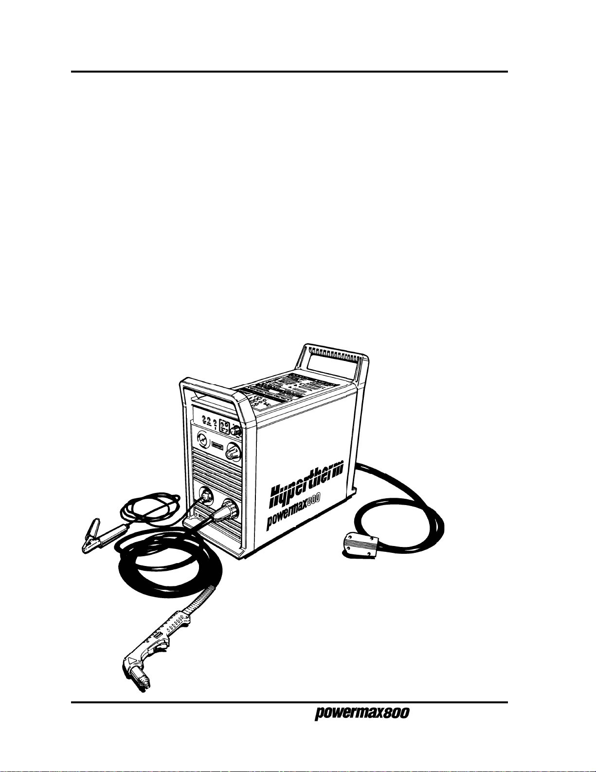
INTRODUCTION
The Powermax800 plasma cutting system uses an inverter power supply to provide a smooth DC
output voltage producing excellent cut and gouge quality on mild steel, stainless steel, aluminum and
other metals. The Powermax800 power supply provides constant-current output variable from 20 to
50 amps, for optimum performance on all thicknesses of metal up to 1/2 inch (12 mm) thick. At 50
amps, the Powermax800 can cut metals up to 3/4 inch (20 mm) thick and will sever metals up to 1
inch (25 mm) thick.
Air is the primary plasma gas, providing low operating cost combined with high-speed performance.
Cylinder air or shop air can be used as long as it is clean, dry and oil-free. When properly set and
maintained, the pressure regulator and gas filter on the power supply ensure that the correct pressure
and flow rate is supplied to the system at the proper quantity and quality. The Powermax800 can also
cut with nitrogen when extended electrode life is a priority.
This service manual provides information for qualified service technicians to troubleshoot and repair
the power supply and torch. Sections 4 and 5 contain in-depth parts lists of the Powermax800
systems. This manual also provides a detailed list of safety practices, so that the system can be
safely tested and maintained. READ THE SAFETY SECTION (Section 1) FIRST!
The Powermax800 operator manual provides setup and daily operating instructions.
2-2
7-97
Figure 2-1 Powermax800 Hand Plasma Cutting System*
* Single-phase 208/240/480V power supply shown.
See Section 5 for part numbers and descriptions of
other Powermax800 power supplies.
Service Manual
Page 18
SPECIFICATIONS
Power Supply
Rated Open Circuit Voltage (OCV) (U0) .............. 300VDC
Rated Output Current (I2) .................................... 20-50 amps
Rated Output Voltage (U2) .................................. 120VDC
Duty Cycle (X) @ 40°C ....................................... 50% (I
Ambient temperature/duty cycle.......................... Power supplies will operate between +14° and
Apparent Input Power (S
Input Voltage (U1)/Input Current (I1)
@ 6 kw Output .................................................... 208V/50A; 240V/43A; 480V/25A - 1φ, 60 Hz
Dimensions and Weight:
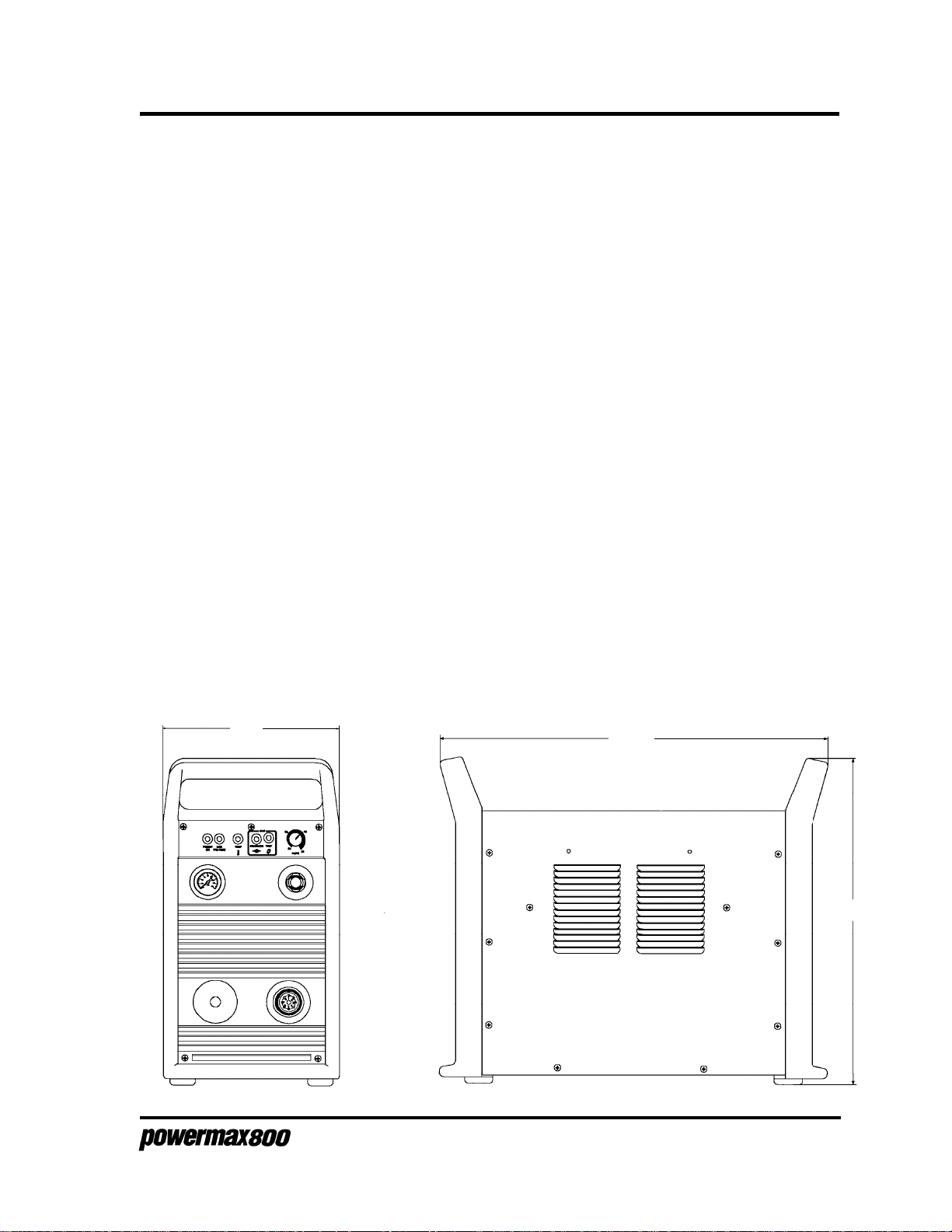
Depth................................................................... 23.1" (590 mm)
Width ...................................................................10.4" (260 mm) without wheels
Height .................................................................. 19.6" (500 mm) without wheels
10.4"
DESCRIPTION & SPECIFICATIONS
=50A, U2=120V)
2
100% (I2=44A, U2=97V) See data tag on power
supply for more information on duty cycle
104° F (-10° and +40° C). Power supplies
operated in an ambient temperature above
86° F (30° C) may show some decrease in
duty cycle.
) .................................. 10.4kVA (U1I1)
1
208V/29A; 240V/25A; 480V/13A - 3φ, 60 Hz
200V/52A; 230V/45A; 400V/30A - 1φ, 50/60 Hz
200V/30A; 230V/26A; 400V/16A - 3φ, 50/60 Hz
400V (CE)/16A - 3φ, 50/60 Hz
600V/11A - 3φ, 60 Hz
15.25" (390 mm) with wheels
23.7" (620 mm) with wheels
27.7" (700 mm) for 600V power supply
23.1"
Figure 2-2 Powermax800 Power Supply with Dimensions
Service Manual
19.6"
2-3
6-96
Page 19
DESCRIPTION & SPECIFICATIONS
Weight ...........................................................................65 pounds (30 kg) without wheels
Gas Type.......................................................................Air or Nitrogen
Gas Quality, Air .............................................................Clean, dry, oil-free
Gas Quality, Nitrogen ....................................................99.995% pure
Gas Inlet Pressure ........................................................ 90 psi (6.2 bar)
Gas Flow .......................................................................320 scfh/5.3 scfm at 90 psi (150 l/min at
Power Supply pressure regulator setting ......................70 psi (4.8 bar) flowing
PAC121 50A TORCHES
Maximum 50A Cutting Capacity (PAC121TS) ..............3/4" (20 mm) @ 50% duty cycle
Maximum 50A Cutting Capacity (PAC121MS)..............3/8" (10 mm) @ 50% duty cycle
Maximum 35A Cutting Capacity (PAC121MS)..............1/4" (6 mm) @ 100% duty cycle
Maximum current at 50% duty cycle .............................50 amps
Gas Flow .......................................................................320 scfh/5.3 scfm at 70 psi (150 l/min at
Gouging Capability (metal removal rate).......................6.3 pounds (2.9 kg)/hr
Weight PAC121TS ........................................................4.5 pounds (2 kg) with 25 ft (7.6 m) lead
Weight PAC121MS .......................................................7 pounds (3.2 kg) with 25 ft (7.6 m) lead
72 pounds (33 kg) with wheels
128 pounds (58 kg) for 600V power supply
6.2 bar) supplied to power supply
pressure regulator
4.8 bar)
7 pounds (3.2 kg) with 50 ft (15 m) lead
9.5 pounds (4.3 kg) with 50 ft (15 m) lead
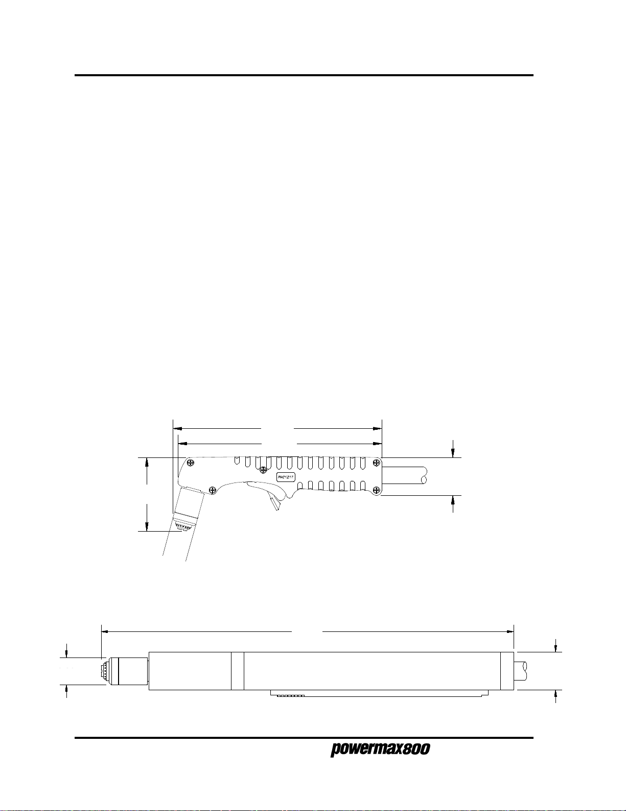
PAC121TS Hand Torch Assembly
8.72"
8.50"
3.10"
1.00"
Figure 2-3 PAC121TS Torch with Dimensions
PAC121MS Machine Torch Assembly
1.58"
15.06"
1.38"1.00"
2-4
10-96
Figure 2-4 PAC121MS Torch with Dimensions
Service Manual
Page 20
DESCRIPTION & SPECIFICATIONS
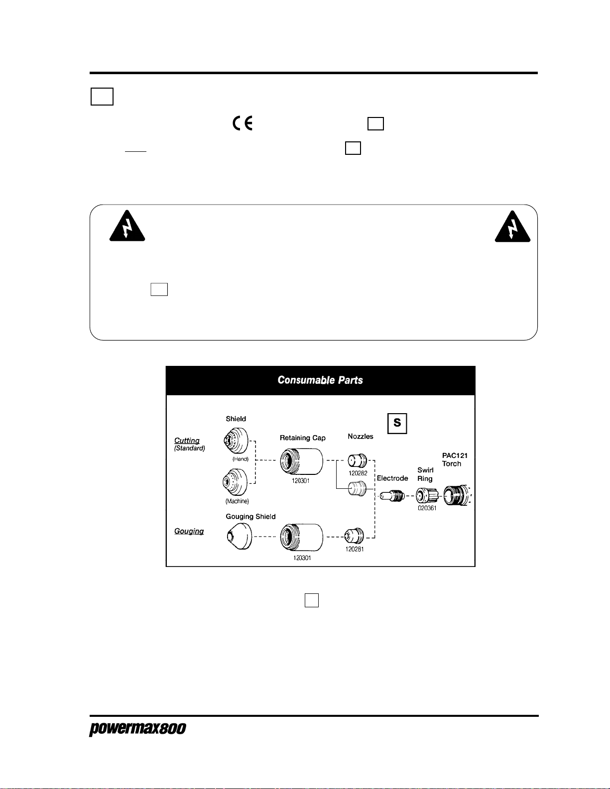
S MARK
The Powermax800 conforms to standard EN50192. The S mark indicates that the power
supply and torch are suitable for use in environments with increased hazard of electrical shock. The
torches must have shielded consumable parts to maintain S mark compliance. See warning below
and Figure 2-5.
WARNING
The voltage between the tip of the torch and the workpiece will exceed 113VDC if
shielded consumable parts are not installed in the torch. If using the 400V CE
power supply, the PAC121TS torch must be operated with shielded parts to maintain the S mark and CE low-voltage compliance for hand held applications. See
Figure 2-5 below and also Section 5:
list of CE consumable parts. This requirement does not apply to machine torch
applications.
Consumable Parts - For CE Compliance
for a
120601
120602
120608
Figure 2-5 S Mark Label.
Service Manual
120438
120573
2-5
7-99
Page 21
DESCRIPTION & SPECIFICATIONS
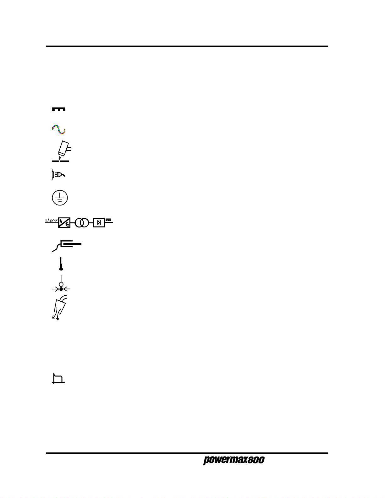
IEC SYMBOLS USED
Direct Current (DC)
Alternating current (AC)
Plasma cutting torch
AC input power connection
The terminal for the external protective (earth) conductor
An inverter-based power source
I
O
Anode (+) work clamp
Temperature switch
Pressure switch
Plasma torch in the TEST position (cooling and cutting gas exiting nozzle)
Power is on
Power is off
Volt/amp curve, "drooping" characteristic
2-6
9-96
Service Manual
Page 22

MAINTENANCE
Section 3 MAINTENANCE
In this section:
Introduction ..........................................................................................3-2
Routine Maintenance ...........................................................................3-2
Bowl Draining/Filter Element Cleaning ............................................3-2
Cooling Air Filter Removal, Cleaning and Replacement..................3-3
Theory of Operation .............................................................................3-4
Sequence of Operation ........................................................................3-6
Troubleshooting....................................................................................3-7
Test Equipment ................................................................................3-7
Troubleshooting Procedures............................................................3-7
Visual Inspection - External .............................................................3-7
Visual Inspection - Internal ..............................................................3-8
Initial Resistance Checks ................................................................ 3-9
Corrective Maintenance Checks....................................................3-17
Power Board ......................................................................................3-26
Control Board .....................................................................................3-28
Control Board LEDs.......................................................................3-28
Control Board Test Points ..............................................................3-29
Torch Check .......................................................................................3-30
Cap Sensor Circuit Check .............................................................3-30
Start Circuit Check.........................................................................3-31
PAC121TS Torch Parts Removal and Replacement ..........................3-32
Torch Main Body Removal and Replacement ............................... 3-32
Torch Switch Removal and Replacement ...................................... 3-33
PAC121MS Torch Parts Removal and Replacement .........................3-34
Removal ........................................................................................ 3-34
Replacement ................................................................................. 3-34
Quick Disconnect O-Ring Removal and Replacement ......................3-36
Service Manual
3-1
9-96
Page 23
MAINTENANCE
INTRODUCTION
This section provides service technicians with routine maintenance, theory of operation and
troubleshooting of the power supply. Also included in this section is the sequence of operation,
power board and control board test points, and the removal and replacement procedures for the
PAC121T trigger torch and PAC121M machine torch parts.
ROUTINE MAINTENANCE
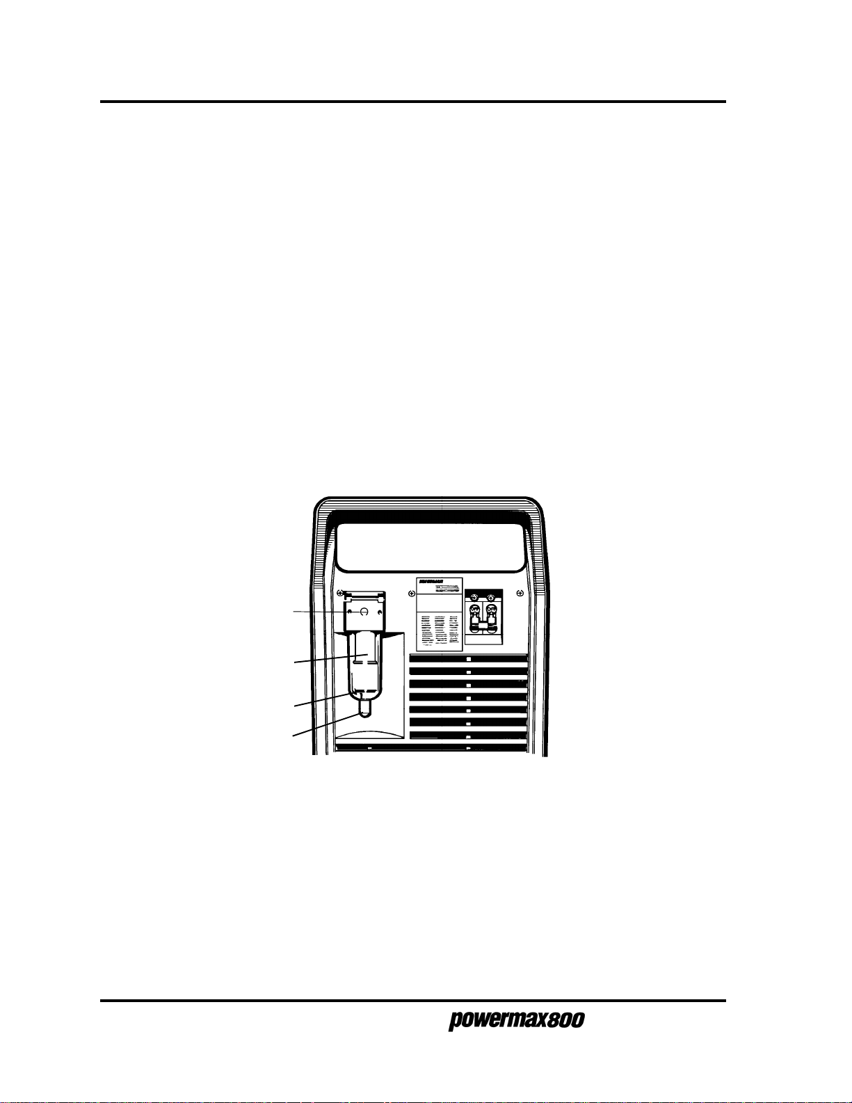
Bowl Draining/Filter Element Cleaning
Moisture coming out of the torch can cause the torch to sputter and hiss. If there is moisture, purge
the lines. If moisture builds up in the bowl of the filter at the rear of the power supply, drain the bowl
and clean the filter element:
1. Shut the gas supply off and disconnect the gas supply hose from the filter assembly
before proceeding.
2. Remove the cap at the bottom of the filter bowl and turn the knurled drain valve to the right to
release water from the bowl.
Gas supply hose
(disconnect)
Filter element
Filter Bowl
Cap
Figure 3-1 Filter Assembly
3. Unscrew the filter bowl.
4. Unscrew the filter element. See
Section 4 for part number information.
5. Clean filter element with alcohol, then blow out with air from the inside of the filter element.
Clean the bowl with household soap only.
6. Replace the filter element and filter bowl.
7. Reconnect the gas supply hose.
Powermax800 Field Upgrade Kits and Optional Parts
in
3-2
Service Manual
Page 24
MAINTENANCE
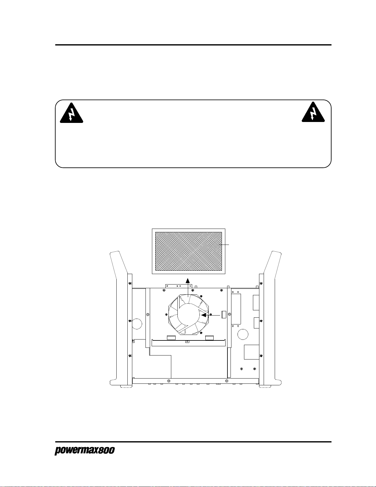
Cooling Air Filter Removal, Cleaning and Replacement
Powermax800 systems are normally shipped without air filters. If your Powermax800 has the air filter
option, it will need cleaning periodically. Excessively dirty or dusty environments can block the
cooling air filter (if installed) and cause the power supply to overheat and shut down.
WARNING
SHOCK HAZARD: Always turn off power and unplug cord from wall and wait 5
minutes before removing any cover of the power supply. If power supply is directly
connected to a line disconnect box, place line disconnect switch to OFF position. In
the U.S., use a "lock-out / tag-out" procedure until the service or maintenance work is
complete. In other countries, follow appropriate local or national safety procedures.
1. Turn the Powermax800 power switch to the OFF (0) position, unplug the power cable
from the wall receptacle and disconnect the gas supply. See warning above.
2. Remove the 22 screws that secure the power supply cover to the chassis.
3. Remove the cover, and remove the cooling air filter from the clips by sliding the filter to the
left and then up - Fig. 3-2.
Air Filter
Figure 3-2 Air Filter Removal
4. Clean the air filter with either soap and water or with low pressure compressed air.
5. Replace the dry filter in the power unit with the wire mesh facing the fan.
6. Replace and re-fasten the power supply cover with the existing screws.
Service Manual
3-3
3-96
Page 25
MAINTENANCE
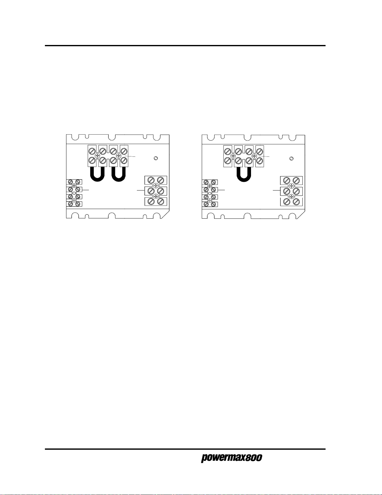
THEORY OF OPERATION
General
The Powermax800 is a multi-voltage, multi-phase power supply. The two inverter inputs are linked in
parallel
The inverters are linked in
400V units. The inverter links are located in the link box, behind the rear panel at TB3. See Fig. 3-3.
The 400V CE power supply does not have a link box.
for 208 or 240V on the 208/240/480V units, and for 200 or 230V on the 200/230/400V units.
series
for 480V on the 208/240/480V units, and for 400V on the 200/230/
TB3
TB2 TB1
208 or 240V Links on 208/240/480V units
and
200 or 230V Links on 200/230/400V units
Figure 3-3 Inverter Links
TB2 TB1
480V Link on 208/240/480V units
and
400V Link on 200/230/400V units
TB3
Functional Description
Refer to block diagram 3-4, Figure 3-3 and the system wiring diagram. See Section 4: Parts List to
identify system components referenced in this description.
AC power enters power switch S1 from terminal block TB1. The MOV and filter capacitor block
MOV1 provides spike and noise suppression. A "soft start" is implemented via power board resistors
R1 and R2 and relay RL1, and the main contactor CR1. Once the capacitors on the power board are
charged up and incoming power is within limits, the control board turns on the main contactor. Diode
bridge D1 rectifies the AC to DC. The DC voltage is then supplied to the inverters.
Each inverter consists of several components: an isolated gate bipolar transistor (IGBT - Q1 or Q2), a
coil of the power transformer (T2), a current sense transformer (CS1 or CS2), and sections of the
power board. The inverters operate as a pulse width modulator controlled half-bridge circuit. The
inverters are capacitor fed and transformer coupled, switching at 20 KHZ. The inverter outputs are
connected in series, and are rectified by output diodes D2 and D3.
The output circuitry consists of a current sensor CS4 and transfer sensor CS3 located on the control
board, pilot arc relay CR2, and output inductor L1.
The feedback loop operates as follows: The amp adjust pot P1 is first set to the desired value.
Current sensor CS4 measures the actual output current and compares it at the error amplifier with the
user-set current setting. The error amplifier output is an analog indication of how wide the pulse width
should be to maintain the current setting. The error amplifier output is then fed to the pulse width
modulator chip PWM. The pulse width modulator sends the signal to the gate drive board
transformers, and the gate drive boards in turn drive the inverter IGBTs Q1 and Q2.
3-4
3-96
Service Manual
Page 26
MAINTENANCE
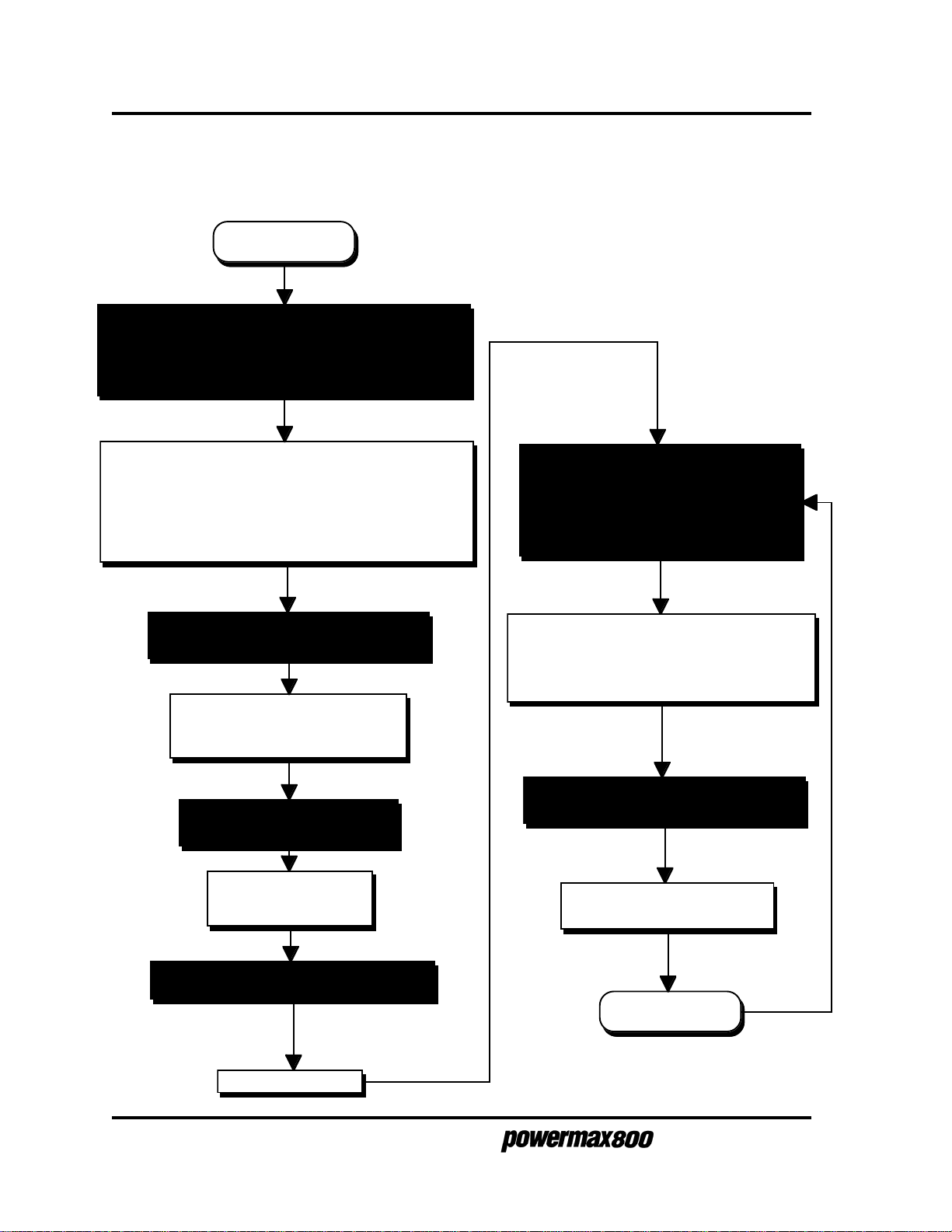
SEQUENCE OF OPERATION
Shaded boxes represent operator action. Clear boxes represent results from operator action.
System off
• Connect gas supply to filter-regulator on power unit
• Apply power at line voltage disconnect box.
• Set power circuit breaker S1 to ON (1).
After five seconds, LINE VOLTAGE and TEMP LEDs
turn off indicating line voltage and transformer
temperatures are within operating limits.
Fan M1 operates and POWER and GAS PRESSURE
LEDs light indicating system is ready for operation.
• Push and hold GAS TEST switch to
check air pressure.
Gas solenoid valve V1 opens to
purge system and to allow setting
of pressure.
• Release GAS TEST switch.
Gas solenoid valve V1
closes. Gas flow stops.
• Connect work cable to workpiece and
position torch on workpiece.
• Depress plasma start switch on hand
torch or remote start switch for machine
torch.
Gas solenoid valve V1 opens and gas flows
Pilot arc relay CR1 closes and pilot arc starts.
Cutting arc transfers to workpiece
Pilot arc relay CR1 opens and pilot arc stops.
• Move torch to make cut. Workpiece
falls away after cut.
Gas solenoid VI closes and gas
flow stops.
• Select cutting current with AMPS knob.
Power circuits ready.
3-6
Power circuits ready
Service Manual
Page 27

TROUBLESHOOTING
MAINTENANCE
The troubleshooting procedures include the
Maintenance Checks.
The complexity of the circuits require that service technicians have a working knowledge of inverter
power supply theory. In addition to being technically qualified, technicians must perform all testing
with safety in mind.
If questions or problems arise during servicing, call the Hypertherm Technical Services Department at
1 800 643 9878.
These procedures are presented in a flow diagram format.
Initial Resistance Checks
and the
Corrective
Test Equipment
• Multimeter
Troubleshooting Procedures
Maintenance of the Powermax800 power supply consists of performing visual inspection and troubleshooting procedures.
• Refer to the system wiring diagram when performing the checkout procedures.
• To locate power supply and torch components refer to Section 4 for 208/240/480V and
200/230/400V power supplies, and Section 5 for 400V CE power supplies.
• After the problem has been located and repaired, refer to the
diagram in this section to test the power unit for proper operation.
Sequence of Operation
flow
Visual Inspection - External
1. Inspect the outside of the power supply for damage to the cover and external components.
2. Inspect the torch and the torch lead for damage.
Service Manual
3-7
Page 28

MAINTENANCE
Visual Inspection - Internal
WARNING
SHOCK HAZARD: Always turn off power and unplug cord from wall and
wait 5 minutes before removing any cover of the power supply. If power
supply is directly connected to a line disconnect box, place line disconnect switch to OFF position. In the U.S., use a "lock-out / tag-out" procedure until the service or maintenance work is complete. In other countries, follow appropriate local or national safety procedures.
If power is required for servicing, be aware that dangerous voltages exist
within the power supply which could cause serious injury or death. If
questions or problems arise during servicing, call the Hypertherm Technical Services department at 1-800-643-9878.
WARNING
The aluminum heatsink on the power PC board is electrically live when the
plasma is on. In case of an electrical failure of the inverter circuit, the
heatsink may be live when the power is off.
SHOCK HAZARD: The large electrolytic capacitors, (blue-cased cylinders)
located on the power PC board store large amounts of energy in the form
of electrical voltage. Even if the power is off, dangerous voltages exist at
the capacitor terminals on the PC board and on certain areas of the
PC board. Never discharge the capacitors with a screwdriver or other
implement... explosion, property damage and/or personal injury will result.
Wait at least 5 minutes after turning the power supply off before touching
the PC board or capacitors. If questions or problems arise during
servicing, call Hypertherm Technical Services at 1-800-643-9878.
3-8
Service Manual
Page 29
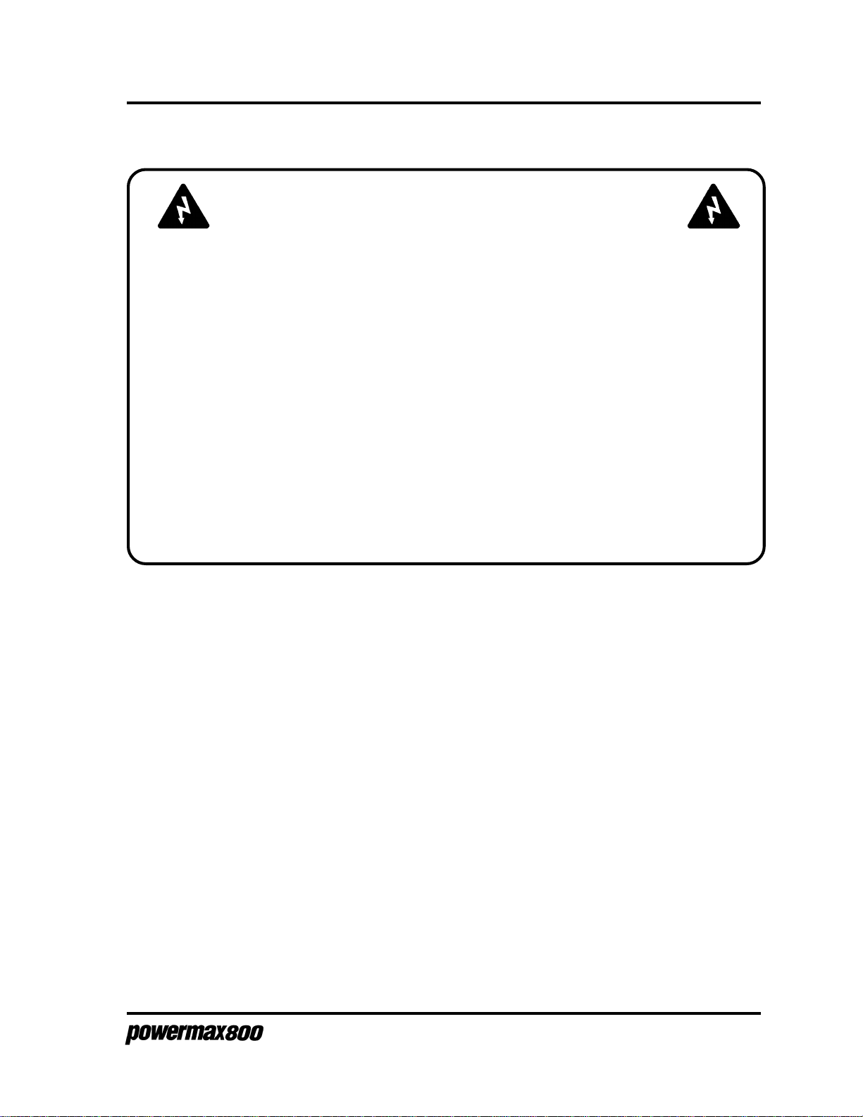
MAINTENANCE
WARNING
SHOCK HAZARD: Do not attempt repairs on the power board or control
board. Do not in any way cut away or remove the protective conformal
coating from either board. To do so will risk a short between the AC input
circuit to the output circuit and may cause serious injury or death.
The power supply and PC boards are subjected to dielectric and insulation resistance tests per applicable CSA and IEC standards for the safety
of the operator and service technicians.
Removal of the protective conformal coatings and other unauthorized
repairs to the PC boards will void the warranty.
If questions or problems arise during servicing, call the Hypertherm Technical Services department at 1-800-643-9878.
1. Set the Powermax800 power switch to O (off), unplug the power cord, and disconnect the
gas supply - see warnings.
2. Remove the cover of the power supply by removing 22 securing screws.
3. Visually inspect the inside of the power supply, especially on the side with the power board
(see Figures 4-2 and 4-3). Look for broken or loose wiring connections, burn and char
marks, damaged components, etc. Repair or replace as necessary.
Initial Resistance Checks
1. After visually inspecting the exterior and interior of the power supply, always perform the
initial resistance checks before applying power to the power supply. If these checks are not
performed prior to power up, further damage to the power supply could result.
2. Perform the initial resistance checks beginning on the following page.
3. After the problem has been located and repaired, refer to the
diagram in this section to test the power unit for proper operation.
Service Manual
Sequence of Operation
flow
3-9
Page 30

MAINTENANCE
Single-Phase
Check # 1
Set power switch S1 to OFF (0)
Measure resistance between the conductors (line and neutral) on
the plug of the power cord. Do not use the ground conductor on
the plug as a measuring point.
Set power switch S1 to ON (1). Measure resistance between the
conductors (line and neutral) on the plug of the power cord. This
reading is the resistance across the control transformer primary for
the selected input voltage.
To
page 3-13,
Check # 2
Yes
Meter
indicates an open
?
Yes
Meter indicates
18 ohms (200V)
20 ohms (208V)
22 ohms (230V)
22 ohms (240V)
56 ohms (400V)
65 ohms (480V)
?
No
Check power cord and power
switch S1. Replace faulty
component (Fig 4-4)
No
3-10
3-97
Yes
Isolate and check control
transformer T1, power switch S1,
input filter MOV1, capacitor C1,
and associated wiring for shorts.
Repair problem and repeat
check.
Indicates
low ohms or
short
?
No
Indicates
high ohms or
infinity ?
Yes
Isolate and check control
transformer T1, power switch S1,
fuses F1 and F2 and associated
wiring for opens.
Repair problem and repeat check.
Service Manual
Page 31

TB3
MAINTENANCE
Three-Phase
Check # 1
Set power switch S1 of OFF (0)
Measure resistance between the conductors
connected to link box terminal TB1-1 & TB1-2, TB1-1 &
TB1-3, and TB1-2 & TB1-3 on the plug of the power
cord. Do not use the ground pin on the plug as a
measuring point. Note: On the 400V CE power supply,
there is no link box.
TB1
TB2
TB1-3
TB1-2
TB1-1
Link Box Behind Rear Panel
To
page 3-12
L
No
Meter
indicates an
open ?
No
Yes
Set power switch S1 to ON (1). Measure resistance
between the conductors on the plug of the power cord. Do
not use the ground pin on the plug as a measuring point.
The reading between TB1-1 & TB1-2 is the resistance
across the control transformer primary for the selected
input voltage.
Meter indicates open between
TB1-1 & TB1-3, and open between
TB1-2 & TB1-3
?
Yes
Check power cord and
power switch S1. Replace
faulty component (Fig 4-4).
To
page 3-12
R
No Yes
Service Manual
TB1-1 & TB1-2 does meter indicate
Between
18 ohms (200V)
20 ohms (208V)
22 ohms (230V)
22 ohms (240V)
56 ohms (400V)
65 ohms (480V)
?
To
page 3-13
Check # 2
3-11
3-97
Page 32

MAINTENANCE
From
page 3-11
L
No
Indicates
low ohms or
short
?
No
Yes
Isolate and check control transformer T1,
power switch S1, input filter MOV1,
capacitors C1, C2 and C3,
contactor CR1 and all associated wiring
for shorts.
Repair problem and repeat check.
From
page 3-11
R
To
page 3-13
Check # 2
No
To
page 3-11
Three-Phase
Check # 1
Indicates
low ohms or short
?
Yes
Isolate and check
control transformer T1,
power switch S1,
input filter MOV1,
capacitor C1,
and associated wiring for shorts.
Repair problem and repeat check.
No
Indicates
high ohms or
infinity ?
Yes
Isolate and check
control transformer T1,
power switch S1,
fuses F1 and F2,
and associated wiring for opens.
Repair problem and repeat check.
3-12
Service Manual
Page 33

Disconnect torch lead.
Place + lead of ohm meter to upper bar spanning output diodes D2 and D3.
Place – lead of ohm meter to lower bar spanning output diodes D2 and D3.
Replace diodes D2 and D3.
Place – lead of ohm meter to upper bar spanning output diodes D2 and D3.
Place + lead of ohm meter to lower bar spanning output diodes D2 and D3.
No
MAINTENANCE
Check #2
All Power
Supplies
Meter indicates
infinity or high
Kohms
?
Yes
Upper bar spanning D2&D3
Lower bar spanning
D2&D3
Location of Bars Spanning D2 and D3
Meter indicates
1.7K ohms
?
Yes
To
page 3-14
Check # 3
No
Replace diodes D2 and D3.
Service Manual
3-13
Page 34

MAINTENANCE
Check # 3
All Power Supplies
Start
Measure resistance between the power supply
chassis and the conductors on the plug of the power
cord. Do not use the ground conductor on the plug as a
measuring point.
Yes
Meter indicates
an open ?
No
There is an internal short in the power supply.
Visually and with a meter, inspect the unit for
pinched, broken, and loose wires and wires with
damaged insulation contacting the chassis. Also
check for loose hardware such as screws, nuts and
bolts.
Problem found
and repaired ?
Yes
3-14
To
page 3-15
Check # 4
No
Continue checking out unit until
problem is found. Then repeat
check.
Service Manual
Page 35

Check # 4
All Power Supplies
Start
Measure resistance between the power
supply chassis and the work cable clamp
(Fig 4-1).
MAINTENANCE
Yes
Meter indicates
an open ?
No
There is an internal short in the power supply. Visually
and with a meter, inspect the unit for pinched, broken,
and loose wires and wires with damaged insulation
contacting the chassis. Also check for loose hardware
such as screws, nuts and bolts.
Problem found
and repaired ?
Yes
To
page 3-16
Check # 5
Continue checking out unit until
problem is found. Then repeat
check.
Service Manual
No
3-15
Page 36

MAINTENANCE
Check # 5
All Power Supplies
Start
Measure resistance between the conductors on the plug of
the power cord and the work cable clamp. Do not use the
ground conductor on the plug as a measuring point.
Yes
Meter indicates
an open ?
No
There is an internal short in the power supply. Visually and
with a meter, inspect the unit for pinched, broken, and
loose wires and wires with damaged insulation contacting
the chassis. Also check for loose hardware such as
screws, nuts and bolts.
Problem found
and repaired ?
Yes
3-16
End of
resistance checks.
To
page 3-17
No
Continue checking out unit until
problem is found. Then repeat
check.
Service Manual
Page 37

MAINTENANCE
Corrective Maintenance Checks
WARNING
SHOCK HAZARD: Always turn off power and unplug cord from wall and
wait 5 minutes before removing any cover of the power supply. If power
supply is directly connected to a line disconnect box, place line disconnect switch to OFF position. In the U.S., use a "lock-out / tag-out" procedure until the service or maintenance work is complete. In other countries, follow appropriate local or national safety procedures.
If power is required for servicing, be aware that dangerous voltages exist
within the power supply which could cause serious injury or death. If
questions or problems arise during servicing, call the Hypertherm Technical Services department at 1-800-643-9878.
WARNING
The aluminum heatsink on the power PC board is electrically live when the
plasma is on. In case of an electrical failure of the inverter circuit, the
heatsink may be live when the power is off.
SHOCK HAZARD: The large electrolytic capacitors, (blue-cased cylinders)
located on the power PC board store large amounts of energy in the form
of electrical voltage. Even if the power is off, dangerous voltages exist at
the capacitor terminals on the PC board and on certain areas of the
PC board. Never discharge the capacitors with a screwdriver or other
implement... explosion, property damage and/or personal injury will result.
Wait at least 5 minutes after turning the power supply off before touching
the PC board or capacitors. If questions or problems arise during
servicing, call Hypertherm Technical Services at 1-800-643-9878.
Service Manual
3-17
Page 38

MAINTENANCE
WARNING
SHOCK HAZARD: Do not attempt repairs on the power board or control
board. Do not in any way cut away or remove the protective conformal
coating from either board. To do so will risk a short between the AC input
circuit to the output circuit and may cause serious injury or death.
The power supply and PC boards are subjected to dielectric and insulation resistance tests per applicable CSA and IEC standards for the safety
of the operator and service technicians.
Removal of the protective conformal coatings and other unauthorized
repairs to the PC boards will void the warranty.
If questions or problems arise during servicing, call the Hypertherm Technical Services department at 1-800-643-9878.
If no problems were found during the initial resistance checks and the power supply still does not
operate correctly, perform the following corrective maintenance checks.
Note: The corrective maintenance flow charts are "best-guess" solutions. Study the system wiring
diagram and understand the theory of operation before troubleshooting. Before purchasing a major
replacement component, check with Hypertherm's Technical Service group at 1 800 643 9878 or the
nearest Hypertherm repair facility.
1. Connect the torch lead to the power supply.
2. Connect the power cord into the line voltage disconnect switch box or plug into a properly
grounded outlet.
3. Connect the gas supply to the pressure regulator at the rear of the power supply.
4. Perform the corrective maintenance checks starting on the following page.
5. After the problem has been located and repaired, refer to the
section for the normal operation of the power supply from power up to cutting.
Sequence of Operation
in this
3-18
Service Manual
Page 39

Start
MAINTENANCE
To
page 3-20
Set power switch S1 to ON (1)
No
S1 shuts OFF
?
.
Yes
LINE VOLTAGE LED
lights briefly
before shutdown
?
No
At torch, check that retaining cap is on tightly and that
consumables are properly installed. Loosen retaining cap and
listen for cap sense microswitch to open (click). Tighten
retaining cap and listen for switch to close
Replace
torch main
body and
switch.
No
Microswitch
opens & closes
?
Yes
With retaining cap tightened,
disconnect connector JP8 at
Control PCB (Fig 4-2). Measure
resistance between JP8
sockets 9&10. Ensure cap
sense microswitch is closed.
.
Replace
Power Board
Control board
replacement fix
page 3-20
No
problem
?
Yes
To
Yes
Yes
Correct voltage links. See
label in linkbox and
Powermax800 Operator
Manual (IM227) Section 3.
Note: 400V CE power supplies
have no link box
No
Power supply
linked for proper
line voltage?
Correct
supply
voltage
Yes
Is line voltage for:
200V > 235V?
208V > 239V?
230V > 270V?
240V > 276V?
400V > 470V?
480V > 552V?
600V > 690V?
No
Replace Control Board
and repeat test
Yes No
See Torch Check, Cap
Sensor Circuit later in this
section.
Service Manual
Meter
indicates 0 ohms
?
Replace torch main
body and switch or
torch lead. See also,
Torch Check, Cap
Sensor Circuit later in
this section.
Disconnect torch lead. Measure resistance
between pins 2 & 8 of torch lead plug.
No
Meter
indicates 0 ohms
?
Yes
Check connectors, wires W94 and W95
and solder joints. Repair as needed.
See also, Torch Check, Cap Sensor
Circuit later in this section.
3-19
9-96
Page 40

MAINTENANCE
From
page 3-19
POWER ON
LED On ?
No
Unplug power cord. Measure resistance
of fan M1
208/240/480V units- approx. 190 ohms
200/230/400V units- approx. 130 ohms
No
Yes
Fan M1 On
?
Yes
Resistance
correct ?
Replace M1
To
page
3-21
No
Yes
Check connectors &
wires between fan and
control board
.
connector JP2 pins 12
& 14.
No
Fan M1 On ?
Yes
No
Measure input line voltage at
power switch S1:
Single-phase units - between P1 & P2.
Three-phase units - between P1 & P2,
P2 & P3 and P1 & P3.
Voltage
correct ?
Yes
Measure input line voltage at control
board connector
JP2 pins 1 & 2 for 24VAC;
JP2 pins 6 & 7 for 27VAC;
JP2 pins 9 & 11 for 120VAC.
Yes
At control board connector JP2, check
terminals 1 & 2 for 24VAC and terminals
6 & 7 for 27VAC.
Voltages
correct?
No
Check main
No
power coming
into power
supply.
Wires and
connectors
Repair or replace
as needed
Yes
Check wiring between T1 and
control board. If wiring is OK,
replace T1.
Replace control board
OK?
No
3-20
3-96
Voltages
correct ?
Yes
Replace control board
No
Unplug power cord.
Measure resistances of
fuses F1 & F2
Meter
indicates
0 ohms ?
Yes
Check connectors & wires
between fuses and T1.
Repair as needed.
Service Manual
No
Replace F1
and/or F2.
Page 41

From
page 3-20
Yes
MAINTENANCE
LINE VOLTAGE
LED
Off?
No
Check for low input
voltage at TB1
Is line voltage for:
200V < 170V?
208V < 178V?
230V < 195V?
240V < 204V?
400V < 340V?
480V < 408V?
600V < 510V?
No
Yes
Check connectors
& wires between
fuses and T1.
Repair as needed.
Correct supply voltage
Yes
Meter
indicates
0 ohms ?
To
page 3-22
NoYes
Replace F1
and/or F2.
Check to see if D27 is
illuminated
D27
illuminated?
Yes
Replace control board
Check control board JP2:
No
24VAC at pins 1 & 2;
27VAC at pins 6 & 7
Service Manual
Unplug power cord.
Measure resistances of
fuses F1 & F2
No
Voltages
correct?
Yes
Replace control board
3-21
9-96
Page 42

MAINTENANCE
From
page 3-21
Yes
GAS PRESSURE
LED On ?
No
Yes
To
page 3-23
Check pressure regulator
gauge for 70 psi
70 psi?
Yes
Disconnect wires W92 & W93 on
pressure switch PS1. Measure
voltage.
24 VAC ?
No
Adjust pressure
regulator for 70 psi
Yes
Replace
PS1.
Yes
Pressure
corrected?
No
Check inlet gas supply pressure
to pressure regulator. It should
be a minimum of 90 psi (6.2 bar)
Inlet Pressure
Ok ?
Yes
No
Adjust inlet
pressure for 90
psi (6.2bar)
.
No
Unplug power cord. Reconnect
wires W92 & W93 to PS1.
Disconnect JP8 from control
PCB. Measure resistance
between JP8 sockets 7 & 8.
3-22
0 ohms ?
Yes
Replace control
PCB.
Check hose from supply to
regulator, pressure regulator
filter element and pressure
regulator. Replace as
required.
Check connections and
No
wiring between control board
JP8 and terminals on PS1.
Service Manual
Page 43

From
page 3-22
Yes
TEMP LED
Off ?
No
Unplug power cord. Allow
power supply to cool down to
room temperature. Plug in
power cord and turn power
supply on.
TEMP
LED remains
Off ?
Yes
Replace temperature switch TS1.
If TS1 opens again after replacement,
replace heat sink SA.
Yes
No
0 ohms?
Yes
MAINTENANCE
To
page 3-24
Disconnect temperature switch
TS2 wires W88 & W99 at power
transformer T2. Measure
resistance across wires coming
from transformer.
No
Unplug power cord. Allow power
supply to cool down to room
temperature. Disconnect JP8 from
control PCB. Measure resistance
between JP8 sockets 1 & 2 and
3 & 4.
0 ohms ?
Yes
Temperature switches are
functioning.
Problem is either with transformer
T2, heatsink SA, control board or
associated wiring.
No
Problem is either
with transformer T2,
heatsink SA, control
board or associated
wiring.
Disconnect temperature
switch TS1 wires W86 & W87
at heatsink SA. Measure
resistance across
temperature switch.
Yes
0 ohms?
No
Replace transformer
T2.
Service Manual
3-23
Page 44

MAINTENANCE
From
page 3-23
Yes
Press & hold GAS TEST switch S2.
Adjust pressure regulator for 70 psi
(4.8 bar) indication (dynamic) on
gauge.
70 psi (4.8 bar)
dynamic ?
Yes
No Yes
Indicates 0 psi
?
No
Check JP4 sockets and control
board pins 5 & 6. Check wires
W65 & W66. Check gas
solenoid V1 & pressure
regulator. If no problems are
found replace control PCB.
Ensure GAS TEST switch S2 has
been released. Press torch start
switch to fire pilot arc.
Pilot arc
fires ?
No
Yes
To
page 3-25
Check control board TP2
for 12V when torch start
switch is pressed.
12V?
Yes
Check JP4 sockets
and control board
pins 1 & 2.
Check wires W61 &
W62.
Check pilot arc relay
CR2.
Repair or replace as
needed.
No
Check regulator &
hoses for leaks.
Check regulator &
hoses for leaks.
Air coming
out of torch?
Yes
No
Relay CR2
closes when
torch start
switch is
pressed
?
Yes
Unplug power supply. Disconnect
control board connector JP8.
Measure resistance between JP8
sockets 5 & 6 while pressing torch
start switch.
No
Disconnect torch lead and check pins
6 & 7 of torch lead plug when torch
start button is pressed.
Check wiring from power
supply quick disconnect
to control board JP8.
Check
consumables and
replace nozzle, if
necessary.
0 ohms ?
No
0 ohms ?
Yes
Wiring
OK?
No
Repair wiring
as needed.
See Torch
Check Start
Circuit later in
this section.
See Torch
Check Start
Circuit later
NoYes
in this
section.
Yes
See Torch
Check Start
Circuit later
in this
section.
3-24
9-96
Service Manual
Page 45

From
page 3-24
Yes
Connect work clamp to workpiece. Set
AMPS control P1 to minimum (20 amps).
Depress torch start switch to transfer arc to
workpiece.
MAINTENANCE
Arc transfers
?
Replace
control
board
Yes
Set AMPS control to maximum (50
amps). Depress torch start switch
to transfer arc to workpiece to see
if cutting current is adjustable.
Check TP1 of
No
control board for
12V.
Yes
12V?
No
Check that work clamp is
making good
metal-to-metal contact.
Work
clamp
OK?
No
Repair or replace work
cable and clamp.
Yes
Replace
consumables.
If arc does not
transfer after
changing
consumables,
replace
control board.
Replace AMPS control
pot P1. If new pot
does not fix problem,
replace control board.
No
Cutting current
adjustable ?
Yes
Corrective maintenance
checks complete.
Service Manual
3-25
Page 46

MAINTENANCE
POWER BOARD
The power board contains part of a "soft start' or "in-rush" circuit, an over-voltage shut down circuit,
and the high-voltage power circuits for left and right inverters. Voltages can be taken at the rear of
the power PCB to check these functions.
WARNING
SHOCK HAZARD: The "E" terminals and J1 are accessible from the back
side of the power PCB. Use extreme caution when taking these readings.
Voltages up to 300 VDC are present at the rear of the power PCB.
The large electrolytic capacitors, (blue-cased cylinders) located on the
front side of the power PC board store large amounts of energy in the
form of electrical voltage. Even if the power is off, dangerous voltages
exist at the capacitor terminals on the PC board and on certain areas of
the PC board. Never discharge the capacitors with a screwdriver or other
implement... explosion, property damage and/or personal injury will
result.
Wait at least 5 minutes after turning the power supply off before handling
the PC board or capacitors. If questions or problems arise during
servicing, call Hypertherm Technical Services at 1-800-643-9878.
Use extreme caution when taking the voltage readings on the back of the power PCB - see warning
above. Use an isolated or "floating" digital volt meter, since high voltages are present. The following
table lists the test points, their descriptions and values. Refer also to Figure 3-5 to locate test points.
Power Board Test Points
Test Point Description Value
E1 to E3 High-voltage power - Left Inverter +300VDC
E14 to E3 One-half of High-voltage power - Left Inverter +150VDC
E4 to E5 High-voltage power - Right Inverter +300VDC
E15 to E5 One-half of High-voltage power - Right Inverter +150VDC
J1-5 to J1-4 "Soft start" signal from control PCB. After incoming voltage is +12VDC 5 sec. after
accepted by control board, control board sends +12VDC to relay throwing power switch
RL1 on power board. LINE VOLTAGE LED will remain lit until "soft S1.
start" signal is complete (about 5 seconds after S1 is thrown).
J1-6 to J1-4 Shut down signal from power board. Protection circuit on power +12 VDC normally.
board will go low (≈ 0 VDC) to control board to shut down power ≈ 0 VDC if voltage too
9-96 supply if it detects over voltage. high.
3-26
9-96
Service Manual
Page 47

MAINTENANCE
WARNING
SHOCK HAZARD: Do not attempt repairs on the power board or control
board. Do not in any way cut away or remove the protective conformal
coating from either board. To do so will risk a short between the AC input
circuit to the output circuit and may cause serious injury or death.
The power supply and PC boards are subjected to dielectric and insulation resistance tests per applicable CSA and IEC standards for the safety
of the operator and service technicians.
Removal of the protective conformal coatings and other unauthorized
repairs to the PC boards will void the warranty.
If questions or problems arise during servicing, call the Hypertherm
Technical Services department at 1-800-643-9878.
6
E14 - YEL
E7
E9
E10
E15 - BLK/WHT
E12
E1
E2
E3
E4
E5
E6
J1
1
Figure 3-5 Back Side of Power Board - Test Points
Service Manual
3-27
9-96
Page 48

MAINTENANCE
CONTROL BOARD
Control Board LEDs
There are 4 control board LEDs visible from the Powermax800 front panel. There are 6 more LEDs
that are visible only when the cover is removed. See Figure 3-6 for location of LEDs.
• D8 POWER ON: Illuminates when power is applied.
• D15 LINE VOLTAGE: Illuminates when the input voltage is out of limits. This LED will remain
on if the line voltage is too low, and go on briefly before the power supply shuts down if the line
voltage is too high.
Note: LINE VOLTAGE LED always remains on for about 5 seconds after the power supply is
turned on and before a "soft start" signal is sent from the control board to the power board.
The upper and lower range for line voltages are as follows:
Lower Limit Line Voltage Upper Limit
170VAC 200VAC 235VAC
178VAC 208VAC 239VAC
195VAC 230VAC 270VAC
204VAC 240VAC 276VAC
340VAC 400VAC 470VAC
408VAC 480VAC 552VAC
510VAC 600VAC 690VAC
Note: To avoid performance
deterioration of the
Powermax800, input voltage
should be within 10% of the
specified system line voltage
setting.
• D24 OVERCURRENT: Illuminates when CS1 or CS2 senses current above 70 amps.
• D25 PILOT ARC RELAY: Illuminates when pilot arc relay CR2 is energized.
• D26 GAS SOLENOID: Illuminates when gas solenoid is energized (when GAS TEST switch is
pressed or when plasma start is pressed).
• D27 MAIN CONTACTOR: Illuminates when contactor CR1 is energized (following "soft start").
• D29 TEMP LED: Remains off when temperature is within operating limits. It Illuminates when
the thermostat in the power transformer opens (over 110° C (230° F)) or if the heatsink
becomes too hot (over 85°C (185° F)). Overheating can be caused by exceeding the duty
cycle rate.
• D35 GAS PRESSURE: Illuminates when incoming gas pressure sensed by PS1 is within
operating limits (over 39 psi (2.7 bar)).
• D38 ARC TRANSFER: Illuminates when arc transfers to the workpiece.
• D42 PLASMA START: Illuminates when the torch start button is pushed or when start button is
activated from the machine interface.
The control board also controls the sequence required to generate plasma:
• Turns on the inverter when the torch switch button is pressed
• After a short delay, turns on the gas solenoid valve V1 to blow back the electrode
• Monitors the pilot arc for arc transfer
• Ramps the current control command from the pilot arc level (20 amps) to the cut current
selected by the operator
• Turns the inverter off if the arc transfer does not occur within 5 seconds
• Turns the power supply off when the retaining cap is loose or when line voltage is too high
3-28
9-96
Service Manual
Page 49

MAINTENANCE
Control Board Test Points
Test Point Description Value
TP1 Transfer signal. A logic high (12V) indicates that the arc is transferred.
TP2 Start signal. A logic high (12V) indicates that the torch start switch is on.
TP3 GND
TP4 +12V
TP5 Unregulated DC voltage. Approximately 30VDC at nominal input voltage.
TP6 +18V
TP7 INV-ON signal. A logic high (12V) indicates that the inverter is on.
TP8 Transfer latch signal. A logic high (12V) indicates that unit is in transferred mode.
TP9 Temp OK signal. A logic high (12V) indicates that all temperatures are OK.
TP10 Continuous PA threshold voltage. Set to 3.55V by P3.
TP11 7.0V
TP15 Error amplifier reference voltage. During inverter operation this signal is 1.915V at 50A current
setting and .75V at 20A current setting.
TP16 Error amplifier output voltage
TP17 Reference voltage 2.50V
TP18 Output current value signal 38.3mv/amp
TP19 Wiper voltage. 2.5V at 50A current setting and 1.00V at 20A current setting.
TP20 GND
TP21 Buffered, inverted, capacitor feed version of pulse width modulator B signal.
TP22 Buffered, inverted version of pulse width modulator A signal.
Fuses
F1,F2 Cap sensor circuit protection .5A (see Parts List for part number and specifications)
F3,F4 Start circuit protection .5A (see Parts List for part number and specifications)
D8
D15
D29
D35
TP8
TP7
TP1
TP9
D38
TP2
TP17
TP4
P3
TP18
TP10
TP3
TP5
TP6
D24
TP11
TP15
TP16
TP19
TP20
Figure 3-6 Control Board Test Points and LED Locations
TP21
D25
TP22
F1
D26
F2 F3
D27
D42
F4
Service Manual
3-29
9-96
Page 50

MAINTENANCE
TORCH CHECK
A failure of the torch cap sensor circuit will cause the Powermax800 power supply to shut down, and
a failure of the torch start circuit will prevent the torch from firing. If your Powermax800 has either of
these problems and you have followed the
proceed with the following checks.
Cap Sensor Circuit Check
If the torch retaining cap is screwed down tightly and the ON/OFF power switch shuts off, there could
be a problem with the torch cap sensor circuit.
Set the Powermax800 power switch to O (off), unplug the power cable, and disconnect
the gas supply. Always wait 5 minutes before removing any cover of the power
supply.
Corrective Maintenance Checks
WARNING
beginning on page 3-17,
1. Disconnect power and gas. See warning above.
2. Remove the power supply cover.
3. Locate fuses F1 and F2 on the control board. See Fig. 3-6.
4. Check to see if the fuses are open.
If the fuses are open, replace the torch, the torch leads and the control board fuse(s). See
Section 4: Parts List or Section 5: Parts List - CE to order new components.
If the fuses are OK, the retaining cap microswitch is working, the line voltage is OK, and the
power supply continues to shut off, replace the control board.
3-30
9-96
Service Manual
Page 51

MAINTENANCE
TORCH CHECK (cont.)
Start Circuit Check
If the torch start trigger is pressed and there is no pilot arc, there could be a problem with the torch
start circuit.
WARNING
Set the Powermax800 power switch to O (off), unplug the power cable, and disconnect
the gas supply. Always wait 5 minutes before removing any cover of the power
supply.
1. Disconnect power and gas. See warning above.
2. Remove the power supply cover.
3. Locate fuses F3 and F4 on the control board. See Fig. 3-6.
4. Check to see if the fuses are open.
If the fuses are open, replace the torch, the torch leads and the control board fuse(s). See
Section 4: Parts List or Section 5: Parts List - CE to order new components.
If the fuses are OK, the gas supply is OK, pressing the torch switch closes the connection
between JP8 sockets 5 & 6, and the torch does not start, replace the control board.
If the fuses are OK, the gas supply is OK, pressing the torch switch does not close
connection between JP8 sockets 5 & 6, and the torch does not start, replace the torch and
the torch leads.
Service Manual
3-31
9-96
Page 52

MAINTENANCE
PAC121TS TORCH PARTS REMOVAL AND REPLACEMENT
Torch Main Body Removal and Replacement
To remove and replace the torch main body, order the torch main body with cap-on sensor switch
and refer to the following procedure and Figures 3-7 and 3-8.
1 Set the Powermax800 power switch to O (off), unplug the power cable, and disconnect
the gas supply. Disconnect the torch lead quick disconnect from the power supply.
2. Remove the five screws that secure the handle halves together and remove handles from
torch main body, torch switch and safety trigger (Fig. 3-8).
3. Remove the red wires attached to the pilot arc tab (Fig. 3-7).
Note for step 4: Disconnect wires by pulling on terminals. Do not pull on wires.
4. Disconnect the two lead terminals (blue wire in each terminal) from the two white wires of
the cap sensor microswitch (Fig. 3-7).
5. Disconnect the plunger wire from the torch main body by holding the plunger nut with a 1/4"
(6mm) wrench or nut driver and removing the plunger screw (Fig. 3-7).
6. Disconnect the torch main body and torch lead gas fittings using 5/16" (8mm) and 7/16"
(11mm) open-end wrenches.
7. Replace with the new torch main body by reversing these instructions. Note: When
connecting the plunger wire, be certain to keep the plunger wire terminal at the proper angle
as shown in Fig. 3-7 inset. Tighten the plunger screw with 8 lb-in (9 kg-cm) of torque.
8. Install the torch main body and torch switch back into handle (Fig. 3-8). Be certain that torch
switch slides into position above safety trigger, and that trigger movement activates the switch
pushbutton and then releases. While positioning the handle halves together, be careful not to
pinch any wires.
9. Replace the five screws to secure the handle halves together.
White Wires (8)
Torch Lead
Proper plunger
terminal mounting
angle
Pilot Arc
Tab
Cap Sensor
Microswitch
White Wires (2)
Plunger
Terminal
Plunger
Nut
Torch
Main Body
Blue
Wires (2)
Cap Sensor
Microswitch
Plunger
Screw
Red
Wires (2)
Plunger
Wire
3-32
12-97
Figure 3-7 PAC121TS Torch Main Body Removal
Service Manual
Page 53

MAINTENANCE
Torch Switch Removal and Replacement
To remove and replace the torch switch, order the torch switch and two splices (074069) and refer to
the following procedure and Figure 3-8. See page 4-10 for a complete torch parts list.
1. Ensure the Powermax800 power switch is set to O (off), unplug the power cable, and
disconnect the gas supply.
2. Remove the five screws that secure the handle halves together.
3. Remove the torch switch from the handle.
4. Remove the torch switch by cutting the two splices at the torch lead (violet wires).
5. Replace the torch switch by crimping the switch wires and the violet wires from the torch lead
together with the splices.
6. Install the torch switch back into handle. Be certain that torch switch slides into position
above safety trigger, and that trigger movement activates the switch pushbutton and then
releases. While positioning the handle halves together, be careful not to pinch any wires.
7. Replace the five screws to secure the handle halves together.
Handle
Spring
Safety
Trigger
Torch
Switch
Splices
Figure 3-8 PAC121TS Torch Switch Removal
Violet
Wires (2)
Handle
Screw (5)
Service Manual
3-33
12-97
Page 54

MAINTENANCE
PAC121MS TORCH PARTS REMOVAL AND REPLACEMENT
Repair of the PAC121MS machine torch normally requires replacement of the torch main body and/or
the torch lead. Order the torch main body with switch. Refer to Figure 3-9 and perform the steps
below. See page 4-11 for a complete torch parts list.
Removal
1. Set the Powermax800 power switch to O (off), unplug the power cable, and
disconnect the gas supply. Disconnect the torch lead quick disconnect from the
power supply.
2. Unscrew the retaining cap and remove the remaining parts (nozzle, electrode and swirl ring).
3. Remove the O-ring from the torch main body.
4. Remove the three screws securing the torch sleeve to the torch main body.
5. Unscrew the torch position sleeve from the torch sleeve and slide it back out of the way.
6. Remove the screw securing the red wires from the torch lead to the torch main body.
Note for steps 7 and 8: Disconnect wires by pulling on terminals. Do not pull on wires.
7. Disconnect the two lead terminals (four white wires in each terminal) from the two black
plunger wire terminals of the torch main body.
8. Disconnect the two lead terminals (blue wire in each terminal) from the two white wires of the
cap sensor microswitch.
9. Disconnect the torch main body and torch lead gas fitting using the 5/16" (8 mm) and 7/16"
(11 mm) open-end wrenches.
Replacement
1. Remove the O-ring from the replacement torch main body.
Caution: Use caution when removing the O-ring, it can easily be damaged.
2. Connect the torch main body to the torch lead gas fitting using open-end wrenches.
3. Connect the two lead terminals (blue wire in each terminal) to the two white wires of the cap
sensor microswitch.
4. Connect the two lead terminals (four white wires in each terminal) to the two black plunger
wires of the torch main body.
3-34
9-96
Service Manual
Page 55

MAINTENANCE
Shield
Retaining
Cap
Torch
Main Body
Black Plunger
Wires (2)
Red
Wires (2)
Screw
White
Wires (2)
Blue
Wires (2)
White Wires
(4 ea.)
Torch Position
Sleeve
Torch Lead
O-Ring
Cap Sensor
Microswitch
Screw (3)
Torch
Sleeve
Figure 3-9 PAC121MS Torch Assembly
5. Secure the red wires from the torch lead to the torch main body with screw.
6. Position the torch sleeve onto the torch main body and secure it with the three screws.
7. Use caution when installing the O-ring onto the torch main body, it can be easily damaged.
Lightly coat with silicone.
8 Screw the torch position sleeve and the torch sleeve together.
9. When the nozzle, electrode and swirl ring are properly in place, replace the retaining cap with
shield. When the retaining cap is tightened, the microswitch will click, indicating that the torch
main body has been replaced correctly.
10. Align the connector plug key (on torch lead) with the connector receptacle key slot (on power
supply) and push it in until the pins seat.
11. Turn the connector securing ring 1/4 turn counterclockwise to ensure that the securing ring
threads and the connector receptacle threads are aligned prior to tightening. Turn the
connector securing ring clockwise to tighten.
Service Manual
3-35
9-96
Page 56

MAINTENANCE
QUICK DISCONNECT O-RING REMOVAL AND REPLACEMENT
The quick disconnect O-ring on the PAC121 torch leads provides a tight seal between the quick
disconnect plug and the power supply receptacle. This O-ring prevents plasma gas from leaking
during cutting. To remove and replace the O-ring in the event of damage or wear, proceed as follows
and refer to Figure 3-10.
1. Turn the Powermax800 power switch OFF (0).
2. Unplug the power cable or set line disconnect switch to off, and disconnect gas supply.
3. Unscrew and remove the torch lead quick disconnect plug from the receptacle on the power
supply.
4. Remove the O-ring from the quick disconnect as shown in Figure 3-10 using needle nose
pliers, tweezers, etc.
5. Replace O-ring. Ensure it seats properly.
Quick Disconnect
Power/Gas Gland
Figure 3-10 Quick Disconnect O-Ring Removal and Replacement
O-Ring (044009)
3-36
9-96
Service Manual
Page 57

PARTS LIST
Section 4 PARTS LIST
In this section:
Power Supply - 208/240/480V
200/230/400V ............................................................ 4-2
Front ............................................................................................... 4-2
Top and Right Side ......................................................................... 4-4
Bottom and Left Side ...................................................................... 4-6
Rear ................................................................................................ 4-8
PAC121TS Torch Assembly .............................................................. 4-10
PAC121MS Torch Assembly.............................................................. 4-11
Consumable Parts............................................................................. 4-12
Powermax800 Field Upgrade Kits and Optional Parts ...................... 4-13
Power Supplies - 208/240/480V........................................................ 4-13
Power Supplies - 200/230/400V........................................................ 4-13
Recommended Spare Parts - Powermax800 - 208/240/480V .......... 4-14
Recommended Spare Parts - Powermax800 - 200/230/400V .......... 4-14
Service Manual
4-1
6-96
Page 58

PARTS LIST
POWER SUPPLY - 208/240/480V
200/230/400V
Note: See Section 5 Parts List
400V CE for parts and
components of the 400V CE
Powermax800 system.
Front
Index No. Part No. Description Ref. Desig. Quantity
1 001502 Pnl:PMX800 Pwr Unit Plastic Front 1
2 001522 Chassis:PMX800 Pwr Unit 1
3 004675 Spacer:PMX800 Pressure Gauge 1
4 008965 Knob:.850 Dia. 1/4 SFT Blk/Sil 1
4A 075498 Flat washer: .257 .500 .062 Black Nylon 1
5 010917 Label:PMX800 Pwr Unit Control Panel 1
6 023922 Cable w/Clamp:PMX800 Work 20' 1
7 008279 Strain Relief:PG9 X .187-.312 Nylon 1
029955 Manifold SA:PMX800 Pwr Unit 1
8 005112 Pressure Switch:39 Psi .013 Orifice PS1 1
9 006054 Sol. Valve:100# 1/8FPT 24VAC NC V1 1
10 011073 Regulator:0-125 Psig 1/8FPT 1
11 011074 Nut:Regulator Panel Mounting 1
12 015282 Female Elbow:1/8NPTX1/4Push in tube 1
13 015283 Male Elbow:1/8NPX1/4Push in tube 1
14 015285 Male Conn.:1/8NPTX1/4Push in tube 3
15 015517 Nip:1/8 X CL Hex Brass 1
16 015540 Tee:1/8 Brass 1
17 015588 Nip:1/8 X 2"L Brass 1
18 022027 Press. Gauge:160# 1.5" 1/8CBM Panel 1
19 046077 Tubing:1/4"OD .04W Blue Nylon 2.3 ft
029956 Harness:PMX800 Power Unit 1
20 009480 Pot:250-Ohm 1W 10% 1T Cerm P1 1
21 029962 Recept. SA:PMX800 Pwr Unit Quick Disc. 1
22 004532 Locknut:42/43 Quick Disc. Recept. 1
23 008606 Socket:MS Cont 7
24 015282 Female Elbow:1/8NPTX1/4Push in tube 1
25 075362 Flat Washer:1/2 .500 1.50 .125 Nylon 1
Notes: Bold part numbers and descriptions are subassemblies.
Indented normal type items are components of subassemblies
All mounting hardware in power supply drawings shown for reference only.
4-2
7-97
Service Manual
Page 59

POWER SUPPLY - 208/240/480V
200/230/400V
2
PARTS LIST
12
13
14
19
5
4
4A
15
10
8
9
14
1
3
18
11
21
23
7
25
20
19
24
17
16
22
19
Figure 4-1 Powermax800 - Front
Service Manual
6
4-3
7-97
Page 60

PARTS LIST
POWER SUPPLY - 208/240/480V
200/230/400V
Top and Right Side
Note: See Section 5 Parts List
400V CE for parts and
components of the 400V CE
Powermax800 system.
Index No. Part No. Description Ref. Desig. Quantity
1 001521 Pnl:Powermax800 Pwr Unit Center 1
2 003078 Relay:30A NO Mag Blwt QDisc Term CR2 1
3 029674 MOV/Cap Assy:MAX42/43/70 3PH MOV1 1
029957 Heatsink SA:Powermax800 Power Unit 1
4 004721 Heatsink:Powermax800 Pwr Unit 1
5 008904 Thermal Pad:AL-340-180 1
6 008905 Thermal Pad:AL-370-134 2
7 008906 Thermal Pad:AL-380-100 2
8 009849 Resistor:20-Ohm 50W 5% NON-IND 4
9 009850 Resistor:20-Ohm 25W 5% NON-IND 4
10 009918 Capacitor:.012UF 1000WV 10% Poly 4
10A 009968 Capacitor:6800PF 1000WV 10% Poly 4
11 005178 Temp. Switch Opens 85°/Closes 75°C TS1 1
12 029998† IGBT Gate Drive SA:Powermax800 Q1 1
13 029998† IGBT Gate Drive SA:Powermax800 Q2 1
14 109018† Diode:600V 100A UFast Recovery Dual D2 1
15 109018† Diode:600V 100A UFast Recovery Dual D3 1
16 109019† Diode:1600V 100A 3PH Module D1 1
17 041472*** PCB Assy:Pwrmx800 Control - 208/240/480V 1
008989 Fuse:500ma 250V IEC 127-3 Fast F1-F4 (pcb fuse) 4
17 041517**** PCB Assy:Pwrmx800 Control - 200/230/400V 1
008989 Fuse:500ma 250V IEC 127-3 Fast F1-F4 (pcb fuse) 4
18 041532***** PCB Assy:Powermax800-ZB Power 1
19 014137 Current Sense Transformer, 40A CS1 1
20 014137 Current Sense Transformer, 40A CS2 1
21 008301 Fuse Holder:2P 30A 13/32 X 1-1/2 1
22 008809*** Fuse:1A 600V 13/32 X 1-1/2 Slo F1,F2 2
22 008958**** Fuse:1A 500V 10mmX38mm Slo F1,F2 2
029978* Heatsink SA:Powermax800 PA Cont PCB Q3
23 004673* Heatsink:Powermax800 PA Cont
24 008905* Thermal Pad:AL-370-134
25 109020†* Diode:600V 100A Fast IGBT Module
26 041486* PCB Assy:Powermax800 PA Cont
028905** Kit:Powermax800 Machine Interface 208/240/480V
128035** Kit:Powermax800 Machine Interface 200/230/400V
27 041494** PCB Assy:Powermax800 Machine Interface
4-4
9-96
Notes: Bold part numbers and descriptions are subassemblies.
Indented normal type items are components of subassemblies.
All mounting hardware in power supply drawings shown for reference only.
† Order corresponding thermal pads when ordering these items
* Available only on power supplies with the pilot arc control option
** Available only on power supplies with the machine interface option
*** Used only on 208/240/480V power supplies
**** Used only on 200/230/400V power supplies
*****For power supplies with serial numbers before 800-010000, order 128108 power board kit to
replace power board.
Service Manual
Page 61

POWER SUPPLY - 208/240/480V
200/230/400V
27
26
17
6
PARTS LIST
3
1
4
12
13
5
16
21
24
25
23
14
15
22
10A
9
10
8
11
20
19
7
2
18
Figure 4-2 Powermax800 - Top and Right Side
Service Manual
4-5
9-96
Page 62

PARTS LIST
POWER SUPPLY - 208/240/480V
200/230/400V
Note: See Section 5 Parts List
400V CE for parts and
components of the 400V CE
Powermax800 system.
Bottom and Left Side
Index No. Part No. Description Ref. Desig. Quantity
1 001521 Panel:Powermax800 Pwr Unit Center 1
2 001522 Chassis:Powermax800 Pwr Unit 1
3 004667 Bracket:Powermax800 Pwr Unit Fan 1
4 014207*** Xfmr:Powermax800 208-240-480 Control T1 1
4 014208**** Xfmr:Powermax800 200-230-400 Control T1 1
5 014210*** Xfmr:Powermax800 208-240-480 Power T2 (w/TS2) 1
5 014211**** Xfmr:Powermax800 200-230-400 Power T2 (w/TS2) 1
6 014186 Inductor:Powermax800 2MH 50A L1 1
7 027080*** Fan:225CFM 120VAC 50-60HZ M1 1
7 027443**** Fan:260CDM 120VAC 50-60HZ M1 1
029957 Heatsink SA:Powermax800 Power Unit 1
8 004721 Heatsink:Powermax800 Power Unit 1
9 041532***** PCB Assy:Powermax800-ZB Power 1
029978* Heatsink SA:Pwrmx800 PA Cont PCB Q3
10 004673* Heatsink:Powermax800 PA Cont
11 028908** Kit:Powermax800 Cooling Fan Filter
Notes: Bold part numbers and descriptions are subassemblies.
Indented normal type items are components of subassemblies
All mounting hardware in power supply drawings shown for reference only.
* Available only on power supplies with the pilot arc control option
** Available only as an option
*** Used only on 208/240/480V power supplies
**** Used only on 200/230/400V power supplies
***** For power supplies with serial numbers before 800-010000, order 128108 power
board kit to replace power board.
4-6
Service Manual
9-96
Page 63

POWER SUPPLY - 208/240/480V
200/230/400V
PARTS LIST
9
1
8
11
10
6
5
7
4
2
Figure 4-3 Powermax800 - Bottom and Left Side
Service Manual
3
4-7
9-96
Page 64

PARTS LIST
POWER SUPPLY - 208/240/480V
200/230/400V
Note: See Section 5 Parts List
400V CE for parts and
components of the 400V CE
Powermax800 system.
Rear
Index No. Part No. Description Ref. Desig. Quantity
1 001503 Pnl:Powermax800 Pwr Unit Plastic Rear 1
2 001522 Chassis:Powermax800 Pwr Unit 1
3 129068 Circuit Breaker SA:4Pole 480V W/TC S1 1
4 129151 Contactor SA:Powermax800 CR1 1
029955 Manifold SA:Powermax800 Pwr Unit 1
5 011072 Filter:20 Micron 1/8FPT 1
6 015285 Male Connector:1/8NPTX1/4Push in Tube 1
7 011079 Filter Element for 011072 Filter 1
029964 Linecord Panel SA:Powermax800 208/240/480V 1
8 001506* Panel:Powermax800 Power Cord 1
9 008228 Cord Grip:1NPT .690-.990 2Screws 1
10 129114**** Power Cord SA:Powermax800 1
129055 Linecord Panel SA:Powermax800 200/230/400V 1
8 001506** Panel:Powermax800 Power Cord 1
9 008228 Cord Grip:1NPT .690-.990 2Screws 1
10 129115***** Power Cord SA:Powermax800 200V 1
029982 Link Box SA:Powermax800 208/240/480V 1
129058 Link Box SA:Powermax800 200/230/400V
11 001500 Box:Powermax800 Pwr Cord 1
12 008900 Terminal Board:4-Terminal with protector TB3 1
13 008926 Terminal Board:4-Terminal with protector TB2 1
14 008933 Terminal Board:3-Terminal with protector TB1 1
15 008279*** Strain Relief:PG9/5X.187-.312 Nylon
16 123099*** Cable: Powermax800 Machine Interface
008201*** Receptacle Shell: 17-14 Reverse Sex
008186*** Socket:24-20 AWG Type III
Notes: Bold part numbers and descriptions are subassemblies.
Indented normal type items are components of subassemblies
All mounting hardware in power supply drawings shown for reference only.
* Use 129134 to order power cord rear panel for 208/240/480V power supplies if you
have the machine interface option.
** Use 129135 to order power cord rear panel for 200/230/400V power supplies if you
have the machine interface option.
*** Available only with the machine interface option.
**** Single-phase cord with plug used on 208/240/480V systems.
***** 200/230/400V Three-phase cord without plug (129115) not shown in Figure 4-4.
4-8
11-96
Service Manual
Page 65

POWER SUPPLY - 208/240/480V
200/230/400V
PARTS LIST
6
2
1
13
5
7
3
4
9
15
10*****
***** 200/230/400V Three-phase power cord not shown in Figure 4-4
8
Figure 4-4 Powermax800 - Rear
16
12
Service Manual
11
14
4-9
9-96
Page 66

PARTS LIST
PAC121TS Torch Assembly and 25' (7.6 m) Lead - 083003
PAC121TS Torch Assembly and 50' (15.2 m) Lead - 083004
Part Number Description
001288 ...................................... Handle, PAC121T
002244 ...................................... Safety Trigger, PAC121T
005094 ...................................... Switch, Torch Pushbutton
020351 ...................................... Electrode, Air
020361 ...................................... Ring, Swirl
027254 ...................................... Trigger Spring, PAC 121T
027466 ...................................... Ring, Gutcha
075340 ...................................... Screws, P/S, # 4 x 5/8, PH, RND, S/B
120282 ...................................... Nozzle:PAC121 50A Shield
120283 ...................................... Shield:PAC121 50A
120301 ...................................... Cap, Retaining
120556 ...................................... Torch Main Body w/Switch, PAC121T
044016 ............................................ O-Ring:BUNA 90Duro .614X.070
129001* ..................................... Torch Lead, 25 ft. (7.6 m)
129002** ................................... Torch Lead, 50 ft. (15.2 m)
044009 ............................................ Quick Disconnect O-Ring
(not shown)
* Used only in 083003
** Used only in 083004
Note: See page 4-12 for detail of consumable parts
Handle
001288
Trigger
Spring
027254
Safety
Trigger
002244
Torch Main
Body w/Switch
120556
O-Ring
044016
Torch
Pushbutton
Switch
005094
Torch Lead
129001, 25' (7.63 m)
129002, 50' (15.25 m)
Gutcha
Ring
027466
Handle
001288
Screw (5)
075340
4-10
12-97
Figure 4-5 PAC121TS Torch Assembly and Leads
Service Manual
Page 67

PARTS LIST
PAC121MS Torch Assembly and 14 ft (4.3 m) Lead - 083049 w/pigtail, 083054 no pigtail
PAC121MS Torch Assembly and 25 ft (7.6 m) Lead - 083011 w/pigtail, 083056 no pigtail
PAC121MS Torch Assembly and 35 ft (10.6 m) Lead - 083044 w/pigtail, 083057 no pigtail
PAC121MS Torch Assembly and 50 ft (15.2 m) Lead - 083012 w/pigtail, 083058 no pigtail
Part Number Description
020351 ...................................... Electrode
020361 ...................................... Ring, Swirl
020559 ...................................... Sleeve, Machine Torch, PAC121M
020620 ...................................... Sleeve, Torch Position, PAC121M
028923 ...................................... Torch Lead w/pigtail, 14 ft (4.3 m)
028918 ...................................... Torch Lead w/pigtail, 25 ft (7.6 m)
028926 ...................................... Torch Lead w/pigtail, 35 ft (10.6 m)
028919 ...................................... Torch Lead w/pigtail, 50 ft (15.2 m)
128123 ...................................... Torch Lead, no pigtail, 14 ft (4.3 m)
128125 ...................................... Torch Lead, no pigtail, 25 ft (7.6 m)
128126 ...................................... Torch Lead, no pigtail, 35 ft (10.6 m)
128127 ...................................... Torch Lead, no pigtail, 50 ft (15.2 m)
044009 ............................................ Quick Disconnect O-Ring (not shown)
075321 ...................................... Socket Cap, 4-40 X 1/2, HX, SS
075322 ...................................... M/S, 4-40 X 1/4, SL, SZ
120282 ...................................... Nozzle: PAC121 50A Shield
120326 ...................................... Shield: PAC121M Machine Torch
120301 ...................................... Cap, Retaining
120558 ...................................... Torch Main Body w/ Switch, PAC121M
044016 ............................................ O-Ring: BUNA 90 Duro .614X.070
Note: See page 4-12 for detail of consumable parts
Torch Main
Body
120558
Screw (3)
075321
Torch Sleeve
020559
O-Ring
044016
On/Off Pendant (not part of machine torch assembly See
Powermax800 Field Upgrade Kits and Optional Parts
in this section for part numbers)
Screw
075322
Figure 5-8 PAC121MS Torch Assembly and Leads
later
Torch Position
Sleeve
020620
Torch Lead
028923, with pigtail, 14 ft (4.3 m)
028918, with pigtail, 25 ft (7.6 m)
028926, with pigtail, 35 ft (10.6 m)
028919, with pigtail, 50 ft (15.2 m)
128123, no pigtail, 14 ft (4.3 m)
128125, no pigtail, 25 ft (7.6 m)
128126, no pigtail, 35 ft (10.6 m)
128127, no pigtail, 50 ft (15.2 m)
Pigtail
Service Manual
4-11
12-97
Page 68

PARTS LIST
CONSUMABLE PARTS
Shields
120601
Shielded
Nonshielded
120602
Deflector
120303
Gouging Shield
120608
Retaining Cap
120301
120301
120301
Nozzles
120282
50A
120438
40A
020395
120281
Note: See Section 5 Parts List
400V CE for parts and
components of the 400V CE
Powermax800 system.
Figure 4-7 Consumable Parts
Swirl
Electrodes
Ring
120573(Air)
020480 (N2)
020361
PAC121
Torch
Gouging
Deflector
120303
120301
Extended
Consumable Spare Parts Kit (028904)
Part Number Description (Qty.)
001285 ............... Box, Consumable Parts (1)
120573 ............... Electrode (3)
120574 ............... Electrode, Extended (1)
120282 ............... Nozzle, 50A, Shielded (3)
120281 ............... Nozzle, 50A, Gouging (1)
120305 ............... Nozzle, Pipe Saddle, Extended (1)
120601 ............... Shield, T torch, (1)
120608 ............... Shield, Gouging (1)
120303 ............... Deflector (1)
044016 ............... O-Ring (3)
015152 ............... Nipple, 1/8 NPT,QDisc, Steel (1)
015570 ............... Bushing, Reducer, 1/4 X 1/8, Brass (1)
015604 ............... Reducer, 1/4 FPT X 1/8 NPT, Brass (1)
027055 ............... Lubricant, Silicone 1/4 Oz Tube (1)
O-Ring
044016
120304
120574
120305
Mach. Consumable Spare Parts Kit (128030)
Part Number Description (Qty.)
001285 ............... Box, Consumable Parts (1)
120573 ............... Electrode, (4)
120574 ............... Electrode, Extended (2)
120282 ............... Nozzle, 50A, Shielded (2)
120438 ............... Nozzle, 40A, Shielded (2)
120305 ............... Nozzle, Pipe Saddle, Extended (2)
120602 ............... Shield, M torch (1)
120303 ............... Deflector (1)
044016 ............... O-Ring (3)
015152 ............... Nipple, 1/8 NPT,QDisc, Steel (1)
015570 ............... Bushing, Reducer, 1/4 X 1/8, Brass (1)
015604 ............... Reducer, 1/4 FPT X 1/8 NPT, Brass (1)
027055 ............... Lubricant, Silicone 1/4 Oz Tube (1)
4-12
7-99
Service Manual
Page 69

PARTS LIST
POWERMAX800 FIELD UPGRADE KITS AND OPTIONAL PARTS
Part Number Description
028714 ..................................On/Off Pendant w/Lead, 25 ft. (7.6 m) (Also comes standard with most
machine torch system configurations. See note below.)
128061 ..................................On/Off Pendant w/Lead, 50 ft. (15.2 m)
128062 ..................................On/Off Pendant w/Lead, 75 ft. (23 m)
028864 ..................................Kit: Powermax800 Pwr Unit Wheels
028898 ..................................Pilot Arc Controller Kit
028905 ..................................Machine Interface Kit, 208/240/480V
128035 ..................................Machine Interface Kit, 200/230/400V
028907 ..................................Work Cable, 50' (15.2 m)
028908 ..................................Cooling Fan Filter Kit:Powermax800
011079 ..................................Gas Filter Element
129019 ..................................Jumper:Powermax800 Link Box
128032 ..................................Kit: Powermax800 600V
008809 ..................................Fuse:1A 600V 13/32 X 1-1/2 Slo (Used on 208/240/480V power supplies)
008958 ..................................Fuse:1A 500V 10mm X 38mm Slo (Used on 200/230/400V and 400V CE
power supplies)
023206 ..................................Cable: Machine Interface, 25 ft (7.6 m) (Comes standard with machine torch
system configurations and with machine interface kits.)
POWER SUPPLIES - 208/240/480V, 1φ/3φ, 60 HZ
Part For With Pilot Arc With Machine
Number Torch Type Control Interface
083002 Hand No No
083015 Hand Yes No
083016 Machine No Yes
083017 Machine Yes Yes
POWER SUPPLIES - 200/230/400V, 1φ/3φ, 50/60 HZ
Part For With Pilot Arc With Machine
Number Torch Type Control Interface
083030 Hand No No
083033 Hand Yes No
083036 Machine No Yes
083039 Machine Yes Yes
Notes: Contact your distributor or call the nearest Hypertherm office for hand and machine
torch system configurations.
See Section 5 Parts List 400V CE for parts and components of the 400V CE Powermax800
system.
Service Manual
4-13
9-96
Page 70

PARTS LIST
RECOMMENDED SPARE PARTS - POWERMAX800- 208/240/480V
Part Number Description Page Reference
003078 ........................................... Relay:30A NO Mag Blwt QDisc Term ........................................................ 4-5
129068 ........................................... Circuit Breaker SA:4Pole 480V W/TC ........................................................ 4-9
129151 ........................................... Contactor SA:Powermax800 ...................................................................... 4-9
008809 ........................................... Fuse:1A 600V 13/32X1-1/2Slo (2) ............................................................. 4-4
014207 ........................................... Xfmr:Powermax800 208-240-480 Control .................................................. 4-7
014210 ........................................... Xfmr:Powermax800 208-240-480 Power ................................................... 4-7
014186 ........................................... Inductor:Powermax800 2MH 50A .............................................................. 4-7
023922 ........................................... Cable w/Clamp:PMX800 Work 20' ............................................................. 4-3
027080 ........................................... Fan:225CFM 120VAC 50-60HZ ................................................................. 4-7
005112 ........................................... Pressure Switch:39 Psi .013 Orifice ........................................................... 4-3
006054 ........................................... Sol. Valve:100# 1/8FPT 24VAC NC ........................................................... 4-3
011072 ........................................... Filter:20 Micron 1/8FPT .............................................................................. 4-9
011079 ........................................... Filter Element for 011072 Filter .................................................................. 4-9
011073 ........................................... Regulator:0-125 Psig 1/8FPT ..................................................................... 4-3
022027 ........................................... Press. Gauge:160# 1.5" 1/8CBM Panel ..................................................... 4-3
029957 ........................................... Heatsink SA:Powermax800 Power Unit ..................................................... 4-5
109018/008906 .............................. Diode:600V 100A UFast Recovery Dual (2)/Thermal Pad:AL-380-100 (2) 4-5
109019/008904 .............................. Diode:1600V 100A 3PH Module/Thermal Pad:AL-340-180 ....................... 4-5
005178 ........................................... Temp. Switch Opens 85°/Closes 75°C ...................................................... 4-5
009849/008903 .............................. Resistor:20-Ohm 50W 5% NON-IND (4)/Thermal Pad: AL 197-114 (4) .... 4-5
009850/008902 .............................. Resistor:20-Ohm 25W 5% NON-IND (4)/Thermal Pad:AL 103-108 (4) ..... 4-5
009918 ........................................... Capacitor:.012UF 1000WV 10% Poly (4) ................................................... 4-5
009968 ........................................... Capacitor:.6800PF 1000WV 10% Poly (4) ................................................. 4-5
029998/008905 .............................. IGBT Gate Drive SA:Powermax800 (2)/Thermal Pad:AL-370-134 (2) ....... 4-5
041472 ........................................... PCB Assy:Powermax800 Control ............................................................... 4-5
041532 ........................................... PCB Assy:Powermax800-ZB Power .......................................................... 4-5, 4-7
129114 ........................................... Cord/Plug:42 1Phase 8-3SO 3Prong 7'3" .................................................. 4-9
029674 ........................................... MOV/Cap Assy:MAX42/43/70 3PH ............................................................ 4-5
028908 ........................................... Kit:Powermax800 Cooling Fan Filter .......................................................... 4-7
RECOMMENDED SPARE PARTS - POWERMAX800- 200/230/400V
Part Number Description Page Reference
003078 ........................................... Relay:30A NO Mag Blwt QDisc Term ........................................................ 4-5
129068 ........................................... Circuit Breaker SA:4Pole 480V W/TC ........................................................ 4-9
129151 ........................................... Contactor SA:Powermax800 ...................................................................... 4-9
008958 ........................................... Fuse:1A 500V 10mmX38mm SLO (2) ........................................................ 4-4
014208 ........................................... Xfmr:Powermax800 200-230-400 Control .................................................. 4-7
014211 ........................................... Xfmr:Powermax800 200-230-400 Power ................................................... 4-7
014186 ........................................... Inductor:Powermax800 2MH 50A .............................................................. 4-7
023922 ........................................... Cable w/Clamp:PMX800 Work 20' ............................................................. 4-3
027443 ........................................... Fan:260CDM 120VAC 50-60HZ ................................................................. 4-7
005112 ........................................... Pressure Switch:39 Psi .013 Orifice ........................................................... 4-3
006054 ........................................... Sol. Valve:100# 1/8FPT 24VAC NC ........................................................... 4-3
011072 ........................................... Filter:20 Micron 1/8FPT .............................................................................. 4-9
011079 ........................................... Filter Element for 011072 Filter .................................................................. 4-9
011073 ........................................... Regulator:0-125 Psig 1/8FPT ..................................................................... 4-3
022027 ........................................... Press. Gauge:160# 1.5" 1/8CBM Panel ..................................................... 4-3
029957 ........................................... Heatsink SA:Powermax800 Power Unit ..................................................... 4-5
109018/008906 .............................. Diode:600V 100A UFast Recovery Dual (2)/Thermal Pad:AL-380-100 (2) 4-5
109019/008904 .............................. Diode:1600V 100A 3PH Module/Thermal Pad:AL-340-180 ....................... 4-5
005178 ........................................... Temp. Switch Opens 85°/Closes 75°C ...................................................... 4-5
009849/008903 .............................. Resistor:20-Ohm 50W 5% NON-IND (4)/Thermal Pad: AL 197-114 (4) .... 4-5
009850/008902 .............................. Resistor:20-Ohm 25W 5% NON-IND (4)/Thermal Pad:AL 103-108 (4) ..... 4-5
009918 ........................................... Capacitor:.012UF 1000WV 10% Poly (4) ................................................... 4-5
009968 ........................................... Capacitor:.6800PF 1000WV 10% Poly (4) ................................................. 4-5
029998/008905 .............................. IGBT Gate Drive SA:Powermax800 (2)/Thermal Pad:AL-370-134 (2) ....... 4-5
041517 ........................................... PCB Assy:Powermax800 Control ............................................................... 4-5
041532 ........................................... PCB Assy:Powermax800-ZB Power .......................................................... 4-5, 4-7
129115 ........................................... Cord: 2.5mm PVC HD21/22 ....................................................................... 4-9
029674 ........................................... MOV/Cap Assy:MAX42/43/70 3PH ............................................................ 4-5
028908 ........................................... Kit:Powermax800 Cooling Fan Filter .......................................................... 4-7
4-14
9-96
Service Manual
Note: See Section 5 Parts List 400V CE for parts and components of the 400V CE Powermax800 system.
Page 71

PARTS LIST - CE
Section 5 PARTS LIST - CE
In this section:
Power Supply - 400V CE .................................................................... 5-2
Front ............................................................................................... 5-2
Top and Right Side ......................................................................... 5-4
Bottom and Left Side ...................................................................... 5-6
Rear ................................................................................................ 5-8
PAC121TS Torch Assembly .............................................................. 5-10
PAC121MS Torch Assembly.............................................................. 5-11
Consumable Parts - CE .................................................................... 5-12
Powermax800 Field Upgrade Kits and Optional Parts ...................... 5-13
Power Supplies - 400V CE................................................................ 5-13
Recommended Spare Parts - Powermax800 400V CE .................... 5-14
Service Manual
5-1
6-96
Page 72

PARTS LIST - CE
POWER SUPPLY - 400V CE
Note: See Section 4 Parts List
for parts and components of
the non-CE Powermax800
systems.
Front
Index No. Part No. Description Ref. Desig. Quantity
1 001502 Pnl:PMX800 Pwr Unit Plastic Front 1
2 001522 Chassis:PMX800 Pwr Unit 1
3 004675 Spacer:PMX800 Pressure Gauge 1
4 008965 Knob:.850 Dia. 1/4 SFT Blk/Sil 1
4A 075498 Flat washer: .257 .500 .062 Black Nylon 1
5 010917 Label:PMX800 Pwr Unit Control Panel 1
6 023922 Cable w/Clamp:PMX800 Work 20' 1
7 008279 Strain Relief:PG9 X .187-.312 Nylon 1
029955 Manifold SA:PMX800 Pwr Unit 1
8 005112 Pressure Switch:39 Psi .013 Orifice PS1 1
9 006054 Sol. Valve:100# 1/8FPT 24VAC NC V1 1
10 011073 Regulator:0-125 Psig 1/8FPT 1
11 011074 Nut:Regulator Panel Mounting 1
12 015282 Female Elbow:1/8NPTX1/4Push in tube 1
13 015283 Male Elbow:1/8NPX1/4Push in tube 1
14 015285 Male Conn.:1/8NPTX1/4Push in tube 3
15 015517 Nip:1/8 X CL Hex Brass 1
16 015540 Tee:1/8 Brass 1
17 015588 Nip:1/8 X 2"L Brass 1
18 022027 Press. Gauge:160# 1.5" 1/8CBM Panel 1
19 046077 Tubing:1/4"OD .04W Blue Nylon 2.3 ft
029956 Harness:PMX800 Power Unit 1
20 009480 Pot:250-Ohm 1W 10% 1T Cerm P1 1
21 029962 Recept. SA:PMX800 Pwr Unit Quick Disc. 1
22 004532 Locknut:42/43 Quick Disc. Recept. 1
23 008606 Socket:MS Cont 7
24 015282 Female Elbow:1/8NPTX1/4Push in tube 1
25 075362 Flat Washer:1/2 .500 1.50 .125 Nylon 1
Notes: Bold part numbers and descriptions are subassemblies.
Indented normal type items are components of subassemblies
All mounting hardware in power supply drawings shown for reference only.
5-2
7-97
Service Manual
Page 73

POWER SUPPLY - 400V CE
PARTS LIST - CE
12
2
13
14
19
5
4
4A
15
10
8
9
14
1
3
18
11
21
23
7
25
20
19
24
17
16
22
19
Figure 5-1 Powermax800 CE - Front
Service Manual
6
5-3
7-97
Page 74

PARTS LIST - CE
POWER SUPPLY - 400V CE
Top and Right Side
Index No. Part No. Description Ref. Desig. Quantity
1 001521 Pnl:Powermax800 Pwr Unit Center 1
2 003078 Relay:30A NO Mag Blwt QDisc Term CR2 1
129046 Heatsink SA:Powermax800 CE Power Unit 1
3 004721 Heatsink:Powermax800 Pwr Unit 1
4 008947 Thermal Pad:AL-315-114 1
5 008905 Thermal Pad:AL-370-134 2
6 008906 Thermal Pad:AL-380-100 2
7 009849 Resistor:20-Ohm 50W 5% NON-IND 4
8 009850 Resistor:20-Ohm 25W 5% NON-IND 4
9 009918 Capacitor:.012µF 1000WV 10% Poly 4
9A 009968 Capacitor:6800pF 1000MV 10% Poly 4
10 005178 Temp. Switch Opens 85°/Closes 75°C TS1 1
11 029998† IGBT Gate Drive SA:Powermax800 Q1 1
12 029998† IGBT Gate Drive SA:Powermax800 Q2 1
13 109018† Diode:600V 100A UFast Recovery Dual D2 1
14 109018† Diode:600V 100A UFast Recovery Dual D3 1
15 109043† Diode:1600V 30A 3PH Bridge Isol Bplr D1 1
16 041517 PCB Assy:Powermax800 Control 1
008989 Fuse:500ma 250V IEC 127-3 Fast F1-F4 (pcb fuse) 4
17 041532*** PCB Assy:Powermax800-ZB Power 1
18 014137 Current Sense Transformer, 40A CS1 1
19 014137 Current Sense Transformer, 40A CS2 1
20 008301 Fuse Holder:2P 30A 13/32 X 1-1/2 1
21 008752 Fuse Block:3P 30A 600V 13/32X1-1/2" 1
22 008958 Fuse:1A 500V 10mmX38mm Slo F1, F2 2
23 008959 Fuse:20A 500V 10mmX38mm Slo 3
029978* Heatsink SA:Pwrmx800 PA Cont PCB Q3
24 004673* Heatsink:Powermax800 PA Cont
25 008905* Thermal Pad:AL-370-134
26 109020†* Diode:600V 100A Fast IGBT Module
27 041486* PCB Assy:Pwermax800 PA Cont
128036** Kit:Powermax800 Machine Interface
28 041494** PCB Assy:Powermax800 Machine Interface
Note: See Section 4 Parts List
for parts and components of
the non-CE Powermax800
systems.
Notes: Bold part numbers and descriptions are subassemblies.
Indented normal type items are components of subassemblies.
All mounting hardware in power supply drawings shown for reference only.
† Order corresponding thermal pads when ordering these items
* Available only on power supplies with the pilot arc control option
** Available only on power supplies with the machine interface option
*** For power supplies with serial numbers before 800-010000, order 128108 power
board kit to replace power board.
5-4
9-96
Service Manual
Page 75

POWER SUPPLY - 400V CE
28
PARTS LIST - CE
25
16
24
27
23
21
1
3
10
20
13
22
9A
14
8
12
11
5
9
15
4
7
19
18
26
6
2
17
Figure 5-2 Powermax800 CE - Top and Right Side
Service Manual
5-5
9-96
Page 76

PARTS LIST - CE
POWER SUPPLY - 400V CE
Note: See Section 4 Parts List
for parts and components of
the non-CE Powermax800
systems.
Bottom and Left Side
Index No. Part No. Description Ref. Desig. Quantity
1 001521 Panel:Powermax800 Pwr Unit Center 1
2 001522 Chassis:Powermax800 Pwr Unit 1
3 004667 Bracket:Powermax800 Pwr Unit Fan 1
4 014209 Xfmr:Powermax800 CE 400V Control T1 1
5 014211 Xfmr:Powermax800 200-230-400 Power T2 (w/TS2) 1
6 014186 Inductor:Powermax800 2MH 50A L1 1
7 027443 Fan:260CDM 120VAC 50-60HZ M1 1
129046 Heatsink SA:Powermax800 CE Power Unit 1
8 004721 Heatsink:Powermax800 Power Unit 1
9 041532*** PCB Assy:Powermax800-ZB Power 1
029978* Heatsink SA:Pwrmx800 PA Cont PCB Q3
10 004673* Heatsink:Powermax800 PA Cont
11 028908** Kit:Powermax800 Cooling Fan Filter
12 129100 Capacitor SA:Powermax800-CE 1
Notes: Bold part numbers and descriptions are subassemblies.
Indented normal type items are components of subassemblies.
All mounting hardware in power supply drawings shown for reference only.
* Available only on power supplies with the pilot arc control option
** Available only as an option
*** For power supplies with serial numbers before 800-010000, order 128108 power
board kit to replace power board.
5-6
9-96
Service Manual
Page 77

POWER SUPPLY - 400V CE
PARTS LIST - CE
10
9
1
8
12
6
5
7
11
4
2
Figure 5-3 Powermax800 CE - Bottom and Left Side
3
Service Manual
5-7
9-96
Page 78

PARTS LIST - CE
POWER SUPPLY - 400V CE
Note: See Section 4 Parts List
for parts and components of
the non-CE Powermax800
systems.
Rear
Index No. Part No. Description Ref. Desig. Quantity
1 001503 Pnl:Powermax800 Pwr Unit Plastic Rear 1
2 001522 Chassis:Powermax800 Pwr Unit 1
3 129068 Circuit Breaker SA:4Pole 480V W/TC S1 1
4 129151 Contactor SA:Powermax800 CR1 1
029955 Manifold SA:Powermax800 Pwr Unit 1
5 011072 Filter:20 Micron 1/8FPT 1
6 015285 Male Connector:1/8NPTX1/4Push in Tube 1
7 011079 Filter Element for 011072 Filter 1
129048 Linecord Panel SA:Powermax800 CE Pwr Unit 1
8 001571* Panel:Powermax800 Power Cord & EMI 1
9 008782 Strain Relief:3/4NPT .375-.500 1
10 047180 Cord:2.5mm PVC HD21/22 7'3" 1
129049 Electric Line Filter SA:Powermax800 CE 1
11 041505 PCB Assy:Powermax800-CE Line Filter 1
12 004692 Bracket:Powermax800-CE EMI 1
13 008949 Terminal Board: 3-Term 1
14 008279** Strain Relief:PG9/5X.187-.312 Nylon
15 123099** Cable: Powermax800 Machine Interface
008201** Receptacle Shell: 17-14 Reverse Sex
008186** Socket:24-20 AWG Type III
Notes: Bold part numbers and descriptions are subassemblies.
Indented normal type items are components of subassemblies
All mounting hardware in power supply drawings shown for reference only.
* Use 129136 to replace power cord rear panel if you have the machine interface
option.
** Available only with the machine interface option
5-8
11-96
Service Manual
Page 79

POWER SUPPLY - 400V CE
PARTS LIST - CE
14
2
1
5
7
6
3
4
12
10
8
9
Figure 5-4 Powermax800 CE - Rear
Service Manual
11
13
15
5-9
9-96
Page 80

PARTS LIST - CE
PAC121TS Torch Assembly and 25' (7.6 m) Lead - 083003
PAC121TS Torch Assembly and 50' (15.2 m) Lead - 083004
Part Number Description
001288 ...................................... Handle, PAC121T
002244 ...................................... Safety Trigger, PAC121T
005094 ...................................... Switch, Torch Pushbutton
020351 ...................................... Electrode, Air
020361 ...................................... Ring, Swirl
027254 ...................................... Trigger Spring, PAC 121T
027466 ...................................... Ring, Gutcha
075340 ...................................... Screws, P/S, # 4 x 5/8, PH, RND, S/B
120282 ...................................... Nozzle:PAC121 50A Shield
120283 ...................................... Shield:PAC121 50A
120301 ...................................... Cap, Retaining
120556 ...................................... Torch Main Body w/Switch, PAC121T
044016 ............................................ O-Ring:BUNA 90Duro .614X.070
129001* ..................................... Torch Lead, 25 ft. (7.6 m)
129002** ................................... Torch Lead, 50 ft. (15.2 m)
044009 ............................................ Quick Disconnect O-Ring
(not shown)
* Used only in 083003
** Used only in 083004
Note: See page 5-12 for detail of consumable parts
Torch
Handle
001288
Trigger
Spring
027254
Safety
Trigger
002244
Torch Main
Body w/Switch
120556
O-Ring
044016
Pushbutton
Switch
005094
Torch Lead
129001, 25' (7.63 m)
129002, 50' (15.25 m)
Gutcha
Ring
027466
Handle
001288
Screw (5)
075340
5-10
12-97
Figure 5-5 PAC121TS Torch Assembly and Leads
Service Manual
Page 81

PARTS LIST - CE
PAC121MS Torch Assembly and 14 ft (4.3 m) Lead - 083049 w/pigtail, 083054 no pigtail
PAC121MS Torch Assembly and 25 ft (7.6 m) Lead - 083011 w/pigtail, 083056 no pigtail
PAC121MS Torch Assembly and 35 ft (10.6 m) Lead - 083044 w/pigtail, 083057 no pigtail
PAC121MS Torch Assembly and 50 ft (15.2 m) Lead - 083012 w/pigtail, 083058 no pigtail
Part Number Description
020351 ...................................... Electrode
020361 ...................................... Ring, Swirl
020559 ...................................... Sleeve, Machine Torch, PAC121M
020620 ...................................... Sleeve, Torch Position, PAC121M
028923 ...................................... Torch Lead w/pigtail, 14 ft (4.3 m)
028918 ...................................... Torch Lead w/pigtail, 25 ft (7.6 m)
028926 ...................................... Torch Lead w/pigtail, 35 ft (10.6 m)
028919 ...................................... Torch Lead w/pigtail, 50 ft (15.2 m)
128123 ...................................... Torch Lead, no pigtail, 14 ft (4.3 m)
128125 ...................................... Torch Lead, no pigtail, 25 ft (7.6 m)
128126 ...................................... Torch Lead, no pigtail, 35 ft (10.6 m)
128127 ...................................... Torch Lead, no pigtail, 50 ft (15.2 m)
044009 ............................................ Quick Disconnect O-Ring (not shown)
075321 ...................................... Socket Cap, 4-40 X 1/2, HX, SS
075322 ...................................... M/S, 4-40 X 1/4, SL, SZ
120282 ...................................... Nozzle: PAC121 50A Shield
120326 ...................................... Shield: PAC121M Machine Torch
120301 ...................................... Cap, Retaining
120558 ...................................... Torch Main Body w/ Switch, PAC121M
044016 ............................................ O-Ring: BUNA 90 Duro .614X.070
Note: See page 5-12 for detail of consumable parts
Torch Main
Body
120558
Screw (3)
075321
Torch Sleeve
020559
O-Ring
044016
On/Off Pendant (not part of machine torch assembly -
Powermax800 Field Upgrade Kits and Optional Parts
See
in this section for part numbers)
Screw
075322
Figure 5-8 PAC121MS Torch Assembly and Leads
later
Torch Position
Sleeve
020620
Torch Lead
028923, with pigtail, 14 ft (4.3 m)
028918, with pigtail, 25 ft (7.6 m)
028926, with pigtail, 35 ft (10.6 m)
028919, with pigtail, 50 ft (15.2 m)
128123, no pigtail, 14 ft (4.3 m)
128125, no pigtail, 25 ft (7.6 m)
128126, no pigtail, 35 ft (10.6 m)
128127, no pigtail, 50 ft (15.2 m)
Pigtail
Service Manual
5-11
12-97
Page 82

PARTS LIST - CE
CONSUMABLE PARTS - CE
Shields
Shielded
Gouging
120601
120602
Gouging Shield
120608
Retaining Cap
120301
120301
Nozzles
120282
120281
Note: See Section 4 Parts List
for parts and components of
the non-CE Powermax800
systems.
Swirl
Electrode
120573
Ring
020361
O-Ring
044016
PAC121
Torch
Figure 5-7 Consumable Parts - CE
Consumable Spare Parts Kit - CE (128033)
Part Number Description (Quantity)
001285 ...................Box, Consumable Parts (1)
120573 ...................Electrode (3)
020361 ...................Swirl Ring (1)
120282 ...................Nozzle, 50A, Shielded (3)
120281 ...................Nozzle, 50A, Gouging (1)
120601 ...................Shield, T torch, (1)
120602 ...................Shield, M torch (1)
120608 ...................Shield, Gouging (1)
044016 ...................O-Ring (3)
015152 ...................Nipple, 1/8 NPT,QDisc, Steel (1)
015570 ...................Bushing, Reducer, 1/4 X 1/8, Brass (1)
015604 ...................Reducer, 1/4 FPT X 1/8 NPT, Brass (1)
027055 ...................Lubricant, Silicone 1/4 Oz Tube (1)
5-12
7-99
Service Manual
Page 83

PARTS LIST - CE
POWERMAX800 FIELD UPGRADE KITS AND OPTIONAL PARTS
Part Number Description
028714 ..................................On/Off Pendant w/Lead, 25 ft. (7.6 m) (Also comes standard with most
machine torch system configurations. See note below.)
128061 ..................................On/Off Pendant w/Lead, 50 ft. (15.2 m)
128062 ..................................On/Off Pendant w/Lead, 75 ft. (23 m)
028864 ..................................Kit: Powermax800 Pwr Unit Wheels
028898 ..................................Pilot Arc Controller Kit
128036 ..................................Machine Interface Kit, 400V CE
028907 ..................................Work Cable, 50' (15.2 m)
028908 ..................................Cooling Fan Filter Kit:Powermax800
011079 ..................................Gas Filter Element
129019 ..................................Jumper:Powermax800 Link Box
008958 ..................................Fuse:1A 500V 10mm X 38mm Slo (Used on 200/230/400V and
400V CE power supplies)
023206 ..................................Cable: Machine Interface, 25 ft (7.6 m) (Comes standard with machine
torch system configurations and with machine interface kits.)
POWER SUPPLIES - 400V CE, 3φ, 50 HZ
Part For With Pilot Arc With Machine
Number Torch Type Control Interface
083018 Hand No No
083021 Hand Yes No
083024 Machine No Yes
083027 Machine Yes Yes
Notes: Contact your distributor or call the nearest Hypertherm office for hand and machine torch
system configurations.
See Section 4 Parts List for parts and components of non-CE Powermax800 systems.
Service Manual
5-13
9-96
Page 84

PARTS LIST - CE
RECOMMENDED SPARE PARTS - POWERMAX800 400V CE
Page
Part Number Description
Reference
003078 .................................... Relay:30A NO Mag Blwt QDisc Term .............................................................. 5-5
129068 .................................... Circuit Breaker SA:4Pole 480V W/TC ............................................................. 5-9
129151 .................................... Contactor SA:Powermax800 ........................................................................... 5-9
008958 .................................... Fuse:1A 500V 10mm X 38mm GI Slo(2) ......................................................... 5-5
008959 .................................... Fuse:20A 500V 10mm X 38mm GI Slo(3) ....................................................... 5-5
014209 .................................... Xfmr:Powermax800 CE 400V Control ............................................................. 5-7
014211 .................................... Xfmr:Powermax800 200/230/400 Power ......................................................... 5-7
014186 .................................... Inductor:Powermax800 2MH 50A .................................................................... 5-7
023922 .................................... Cable w/Clamp:PMX800 Work 20' .................................................................. 5-3
027443 .................................... Fan:260CDM 120VAC 50-60HZ ...................................................................... 5-7
005112 .................................... Pressure Switch:39 Psi .013 Orifice ................................................................ 5-3
006054 .................................... Sol. Valve:100# 1/8FPT 24VAC NC ................................................................ 5-3
011072 .................................... Filter:20 Micron 1/8FPT ................................................................................... 5-9
011079 .................................... Filter Element for 011072 Filter ....................................................................... 5-9
011073 .................................... Regulator:0-125 Psig 1/8FPT .......................................................................... 5-3
022027 .................................... Press. Gauge:160# 1.5" 1/8CBM Panel .......................................................... 5-3
129046 .................................... Heatsink SA:Powermax800 CE Power Unit .................................................... 5-5
109018/008906 ....................... Diode:600V 100A UFast Recovery Dual (2)/Thermal Pad:AL-380-100 (2) ..... 5-5
109043/008947 ....................... Diode:1600V 30A 3PH Bridge/Thermal Pad:AL-315-114 ................................ 5-5
005178 .................................... Temp. Switch Opens 85°/Closes 75°C ............................................................ 5-5
009849/008903 ....................... Resistor:20-Ohm 50W 5% NON-IND (4)/Thermal Pad:AL-197-114 (4) .......... 5-5
009850/008902 ....................... Resistor:20-Ohm 25W 5% NON-IND (4)/Theral Pad:AL-103-108 (4) ............. 5-5
009918 .................................... Capacitor:.012UF 1000WV 10% Poly (4) ........................................................ 5-5
009968 .................................... Capacitor:6800pF 1000MV 10% Poly (4) ........................................................ 5-5
029998/008905 ....................... IGBT Gate Drive SA:Powermax800 (2)/Thermal Pad:AL-370-134 (2) ............ 5-5
041517 .................................... PCB Assy:Powermax800 Control .................................................................... 5-5
041532 .................................... PCB Assy:Powermax800-ZB Power ......................................................... 5-5, 5-7
129049 .................................... Electric Line Filter SA:Powermax800-CE ........................................................ 5-9
047180 .................................... Cord:2.5mm PVC HD21/22, 7'3" ..................................................................... 5-9
028908 .................................... Kit:Powermax800 Cooling Fan Filter ............................................................... 5-7
See Section 4 Parts List for parts and components of non-CE Powermax800 systems.
5-14
9-96
Service Manual
Page 85

WIRING DIAGRAMS
Section 6 WIRING DIAGRAMS
In this section:
Powermax800 Electrical Schematic: 208/240/480V .......................... 6-2
Powermax800 Electrical Schematic: 200/230/400V .......................... 6-3
Powermax800 Electrical Schematic: 400V–CE ................................. 6-4
Powermax800 Troubleshooting Schematic 1 of 2 .............................. 6-5
Powermax800 Troubleshooting Schematic 2 of 2 .............................. 6-6
Powermax800 CE Troubleshooting Schematic 1 of 2 ........................ 6-7
Powermax800 CE Troubleshooting Schematic 2 of 2 ........................ 6-8
Service Manual
6-1
Page 86

Page 87

Page 88

Page 89

Page 90

Page 91

Page 92

Page 93

APPENDIX A
AERATION MANIFOLD FOR PLASMA CUTTING ALUMINUM
Introduction
When plasma arc cutting aluminum at the water table surface or below water, free hydrogen
gas may be generated by the cutting process. The high temperature of the plasma process
causes disassociation of oxygen and hydrogen from the water in the water table. The hot
aluminum, which has a high affinity for oxygen, then combines with the oxygen leaving free
hydrogen.
An effective means of avoiding free hydrogen buildup is to install an aeration manifold on the
floor of the water table to replenish the oxygen content of the water.
Making an Aeration Manifold - Figure c-1
Make an Aeration Manifold with two-inch (50 mm) PVC tubing with one-inch (25 mm)
Distribution Lines connected to it. Drill 1/8 inch (3 mm) holes every six inches (150 mm) in
the distribution lines. Cap the ends of the distribution lines and install the lines so that
oxygen is delivered to all parts of the cutting area.
Connect the manifold to a shop air line. Set a pressure regulator to obtain a steady stream of
bubbles.
Aeration Manifold
Distribution Lines
Figure a-1 Aeration Manifold
Service Manual
Regulated air in
a-1
Page 94

APPENDIX B
STANDARDS INDEX
For further information concerning safety practices to be exercised with plasma arc cutting equipment, please
refer to the following publications:
1. ANSI Standard Z49.1,
LeJeune Road, P.O. Box 351020, Miami, FL 33135.
2. NIOSH,
dent of Documents, U.S. Government Printing Office, Washington, D.C. 20402.
3. OSHA,
Washington, D.C. 20402.
4. ANSI Standard Z87.1,
able from the American National Standards Institute, 1430 Broadway, New York, NY 10018.
5. ANSI Standard Z41.1, S
Standards Institute, 1430 Broadway, New York, NY 10018.
6. ANSI Standard Z49.2,
American National Standards Institute, 1430 Broadway, New York, NY 10018.
7. AWS Standard A6.0,
the American Welding Society, 550 LeJeune Road, P.O. Box 351040, Miami, FL 33135.
8. NFPA Standard 51,
Fire Protection Association, 470 Atlantic Avenue, Boston, MA 02210.
9. NFPA Standard 70-1978,
tion, 470 Atlantic Avenue, Boston, MA 02210.
Safety and Health in Arc Welding and Gas Welding and Cutting
Safety and Health Standards
Safety in Welding and Cutting
, 29FR 1910, obtainable from the U.S. Government Printing Office,
Safe Practices for Occupation and Educational Eye and Face Protection
tandard for Men's Safety-Toe Footwear
Fire Prevention in the Use of Cutting and Welding Processes
Welding and Cutting Containers Which Have Held Combustibles
Oxygen — Fuel Gas Systems for Welding and Cutting
National Electrical Code
, obtainable from the American Welding Society, 550
, obtainable from the Superinten-
, obtainable from the American National
, obtainable from the National
, obtainable from the National Fire Protection Associa-
, obtain-
, obtainable from the
, obtainable from
10. NFPA Standard 51B,
Association, 470 Atlantic Avenue, Boston, MA 02210.
11. CGA Pamphlet P-1,
Gas Association, 1235 Jefferson Davis Highway, Arlington, VA 22202.
12. CSA Standard W117.2,
Association Standard Sales, 178 Rexdale Boulevard, Rexdale, Ontario M9W 1R3, Canada.
13. NWSA booklet,
1900 Arch Street, Philadelphia, PA 19103.
14. American Welding Society Standard AWS F4.1,
ration for Welding and Cutting of Containers and Piping That Have Held Hazardous Substances
able from the American Welding Society, 550 LeJeune Road, P.O. Box 351040, Miami, FL 33135.
15. ANSI Standard Z88.2,
Standards Institute, 1430 Broadway, New York, NY 10018.
16. Canadian Electrical Code Part 1,
Canadian Standards Association, 178 Rexdale Boulevard, Rexdale, Ontario, Canada M9W1R3.
b-1
Cutting and Welding Processes
Safe Handling of Compressed Gases in Cylinders
Code for Safety in Welding and Cutting
Welding Safety Bibliography
Practices for Respiratory Protection
Safety Standards for Electrical Installations
, obtainable from the National Welding Supply Association,
, obtainable from the National Fire Protection
Recommended Safe Practices for the Prepa-
, obtainable from the American National
, obtainable from the Compressed
, obtainable from the Canadian Standards
, obtainable from the
Service Manual
, obtain-
 Loading...