

Page 1
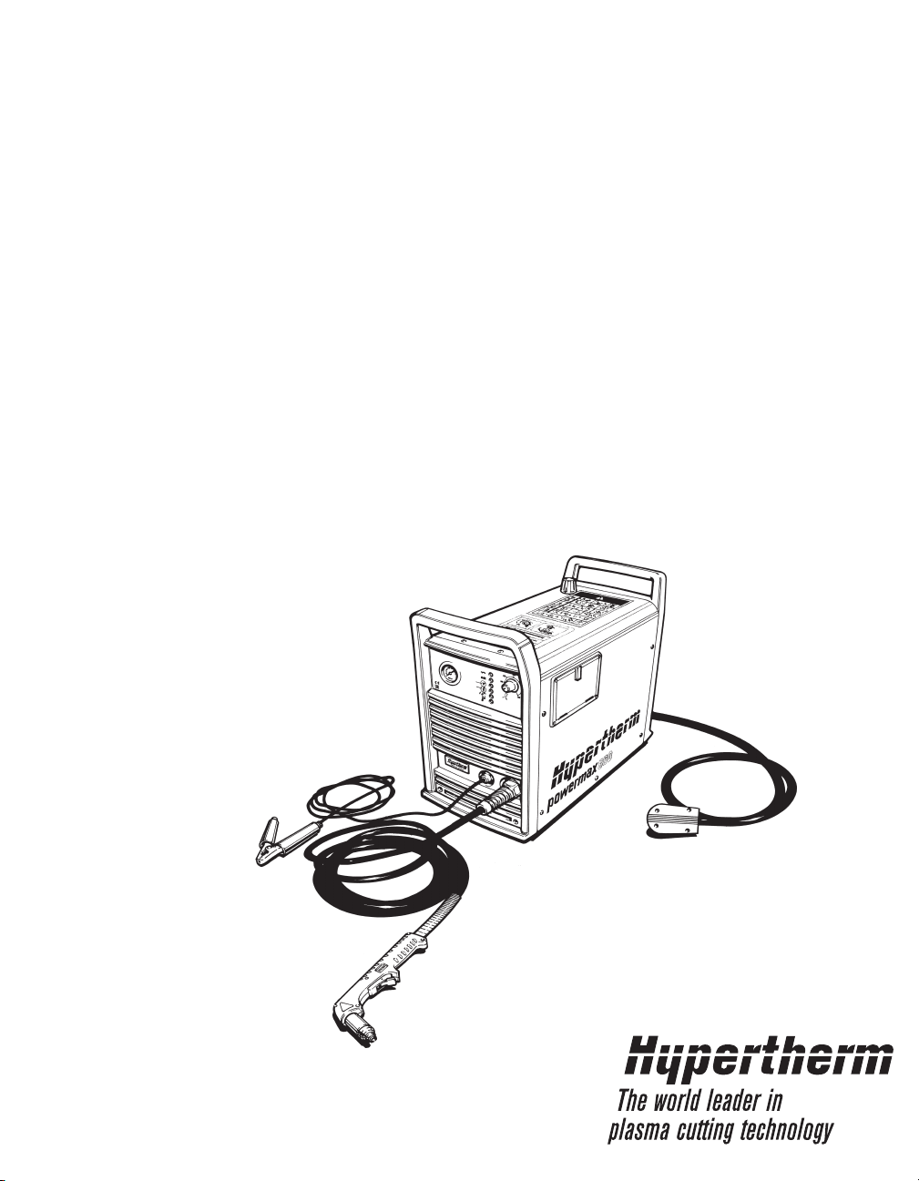
Plasma Arc
Cutting System
Operator Manual
803390 Revision 3
powermax
600
®
Page 2

Plasma Arc Cutting System
Operator Manual
IM-339
(P/N 803390)
© Copyright 2013 Hypertherm, Inc.
All Rights Reserved
Hypertherm and Powermax are trademarks of Hypertherm, Inc.
and may be registered in the United States and/or other countries.
Revision 3 November 2013
Hypertherm, Inc.
Hanover, NH USA
http://www.hypertherm.com
email:info@hypertherm.com
®
powermax600
Page 3

Hypertherm, Inc.
Etna Road, P.O. Box 5010
Hanover, NH 03755 USA
603-643-3441 Tel (Main Office)
603-643-5352 Fax (All Departments)
800-643-9878 Tel (Technical Service)
800-737-2978 Tel (Customer Service)
Hypertherm Automation, LLC
5 Technology Drive
West Lebanon, NH 03755 USA
603-298-7970 Tel
603-298-7977 Fax
Hypertherm Plasmatechnik, GmbH
Technologiepark Hanau
Rodenbacher Chaussee 6
63457 Hanau-Wolfgang, Deutschland
49 6181 58 2100 Tel
49 6181 58 2134 Fax
49 6181 58 2123 (Technical Service)
Hypertherm (S) Pte Ltd
No. 19 Kaki Bukit Road 2
K.B. Warehouse Complex
Singapore 417847, Republic of Singapore
65 6 841 2489 Tel
65 6 841 2490 Fax
65 6 841 2489 (Technical Service)
Japan
1952-14 Yata-Natsumegi
Mishima City, Shizuoka Pref.
411-0801 Japan
81 0 559 75 7387 Tel
81 0 559 75 7376 Fax
Hypertherm UK, Ltd
9 Berkeley Court, Manor Park
Runcorn, Cheshire, England WA7 1TQ
44 1928 579 074 Tel
44 1928 579 604 Fax
France
15 Impasse des Rosiers
95610 Eragny, France
00 800 3324 9737 Tel
00 800 4973 7329 Fax
Hypertherm S.r.l.
Via Torino 2
20123 Milano, Italia
39 02 725 46 312 Tel
39 02 725 46 400 Fax
39 02 725 46 314 (Technical Service)
Hypertherm Europe B.V.
Vaartveld 9
4704 SE Roosendaal, Nederland
31 165 596908 Tel
31 165 596901 Fax
Technical Service:
00 800 49 73 7843 – toll-free in Europe
31 165 596900 Tel
Hypertherm Brasil Ltda.
Rua Visconde de Santa Isabel, 20 – Sala 611
Vila Isabel, RJ
Brasil CEP 20560-120
55 21 2278 6162 Tel
55 21 2578 0947 Fax
3/27/03
Page 4

ELECTROMAGNETIC COMPATIBILITY (EMC)
EMC INTRODUCTION
Hypertherm's CE-marked equipment is built
in compliance with standard EN50199. The
equipment should be installed and used in
accordance with the information below to
achieve electromagnetic compatibility.
The limits required by EN50199 may not be
adequate to completely eliminate interference when the affected equipment is in
close proximity or has a high degree of
sensitivity. In such cases it may be necessary to use other measures to further
reduce interference.
This plasma equipment is designed for use
only in an industrial environment.
INSTALLATION AND USE
The user is responsible for installing and
using the plasma equipment according to
the manufacturer's instructions. If electromagnetic disturbances are detected then it
shall be the responsibility of the user to resolve the situation with the technical assistance of the manufacturer. In some cases
this remedial action may be as simple as
earthing the cutting circuit, see Earthing of
Workpiece. In other cases it could involve
constructing an electromagnetic screen
enclosing the power source and the work
complete with associated input filters. In all
cases electromagnetic disturbances must
be reduced to the point where they are no
longer troublesome.
ASSESSMENT OF AREA
Before installing the equipment the user
shall make an assessment of potential electromagnetic problems in the surrounding
area. The following shall be taken into
account:
a. Other supply cables, control cables,
signalling and telephone cables; above,
below and adjacent to the cutting equipment.
b. Radio and television transmitters and
receivers.
c. Computer and other control equipment.
d. Safety critical equipment, for example
guarding of industrial equipment.
e. Health of the people around, for
example the use of pacemakers and hearing aids.
f. Equipment used for calibration or measurement.
g. Immunity of other equipment in the environment. User shall ensure that other
equipment being used in the environment is
compatible. This may require additional
protection measures.
h. Time of day that cutting or other activities
are to be carried out.
Earthing of Workpiece
Where the workpiece is not bonded to earth
for electrical safety, nor connected to earth
because of its size and position, for example,
ship's hull or building steelwork, a connection
bonding the workpiece to earth may reduce
emissions in some, but not all instances.
Care should be taken to prevent the earthing
of the workpiece increasing the risk of injury
to users, or damage to other electrical equipment. Where necessary, the connection of
the workpiece to earth should be made by a
direct connection to the workpiece, but in
some countries where direct connection is
not permitted, the bonding should be
achieved by suitable capacitances selected
according to national regulations.
Note. The cutting circuit may or may not be
earthed for safety reasons. Changing the
earthing arrangements should only be authorized by a person who is competent to
assess whether the changes will increase
the risk of injury, for example, by allowing
parallel cutting current return paths which
may damage the earth circuits of other
equipment. Further guidance is given in IEC
TC26 (sec)94 and IEC TC26/108A/CD Arc
Welding Equipment Installation and Use.
Screening and Shielding
Selective screening and shielding of other
cables and equipment in the surrounding
area may alleviate problems of interference.
Screening of the entire plasma cutting
installation may be considered for special
applications
The size of the surrounding area to be
considered will depend on the structure of
the building and other activities that are taking place. The surrounding area may extend
beyond the boundaries of the premises.
METHODS OF REDUCING EMISSIONS
Mains Supply
Cutting equipment must be connected to the
mains supply according to the manufacturer's recommendations. If interference
occurs, it may be necessary to take
additional precautions such as filtering of
the mains supply. Consideration should be
given to shielding the supply cable of permanently installed cutting equipment, in
metallic conduit or equivalent. Shielding
should be electrically continuous throughout
its length. The shielding should be connected to the cutting mains supply so that good
electrical contact is maintained between the
conduit and the cutting power source
enclosure
Maintenance of Cutting Equipment
The cutting equipment must be routinely
maintained according to the manufacturer's
recommendations. All access and service
doors and covers should be closed and
properly fastened when the cutting
equipment is in operation. The cutting
equipment should not be modified in any
way except for those changes and adjustments covered in the manufacturer's
instructions. In particular, the spark gaps of
arc striking and stabilizing devices should
be adjusted and maintained according to
the manufacturer's recommendations.
Cutting Cables
The cutting cables should be kept as short
as possible and should be positioned close
together, running at or close to the floor
level.
Equipotential Bonding
Bonding of all metallic components in the
cutting installation and adjacent to it should
be considered. However, metallic components bonded to the workpiece will increase
the risk that the operator could receive a
shock by touching these metallic
components and the electrode at the same
time. The operator should be insulated from
all such bonded metallic components.
Hypertherm Plasma Systems i
Page 5

WARRANTY
ii Hypertherm Plasma Systems
9-01
WARNING
Genuine Hypertherm parts are the factory-recommended
replacement parts for your Hypertherm system. Any damage
caused by the use of other than genuine Hypertherm parts may
not be covered by the Hypertherm warranty.
WARNING
You are responsible for the safe use of the Product.
Hypertherm does not and cannot make any guarantee or
warranty regarding the safe use of the Product in your
environment.
GENERAL
Hypertherm, Inc. warrants that its Products shall be free from
defects in materials and workmanship, if Hypertherm is notified
of a defect (i) with respect to the power supply within a period
of two (2) years from the date of its delivery to you, with the
exception of G3 Series power supplies, which shall be within a
period of three (3) years from the date of delivery to you, and
(ii) with respect to the torch and leads within a period of one (1)
year from its date of delivery to you. This warranty shall not
apply to any Product which has been incorrectly installed,
modified, or otherwise damaged. Hypertherm, at its sole
option, shall repair, replace, or adjust, free of charge, any
defective Products covered by this warranty which shall be
returned with Hypertherm’s prior authorization (which shall not
be unreasonably withheld), properly packed, to Hypertherm’s
place of business in Hanover, New Hampshire, or to an
authorized Hypertherm repair facility, all costs, insurance and
freight prepaid. Hypertherm shall not be liable for any repairs,
replacement, or adjustments of Products covered by this
warranty, except those made pursuant to this paragraph or with
Hypertherm’s prior written consent. The warranty above is
exclusive and is in lieu of all other warranties, express,
implied, statutory, or otherwise with respect to the
Products or as to the results which may be obtained
therefrom, and all implied warranties or conditions of
quality or of merchantability or fitness for a particular
purpose or against infringement. The foregoing shall
constitute the sole and exclusive remedy for any breach
by Hypertherm of its warranty. Distributors/OEMs may offer
different or additional warranties, but Distributors/OEMs are
not authorized to give any additional warranty protection to you
or make any representation to you purporting to be binding
upon Hypertherm.
PATENT INDEMNITY
Except only in cases of products not manufactured by
Hypertherm or manufactured by a person other than
Hypertherm not in strict conformity with Hypertherm’s
specifications and in cases of designs, processes, formulae, or
combinations not developed or purported to be developed by
Hypertherm, Hypertherm will defend or settle, at its own
expense, any suit or proceeding brought against you alleging
that the use of the Hypertherm product, alone and not in
combination with any other product not supplied by
Hypertherm, infringes any patent of any third party. You shall
notify Hypertherm promptly upon learning of any action or
threatened action in connection with any such alleged
infringement, and Hypertherm’s obligation to indemnify shall be
conditioned upon Hypertherm’s sole control of, and the
indemnified party’s cooperation and assistance in, the defense
of the claim.
LIMITATION OF LIABILITY
In no event shall Hypertherm be liable to any person or
entity for any incidental, consequential, indirect, or
punitive damages (including but not limited to lost profits)
regardless of whether such liability is based on breach of
contract, tort, strict liability, breach of warranties, failure of
essential purpose or otherwise and even if advised of the
possibility of such damages.
LIABILITY CAP
In no event shall Hypertherm’s liability, whether such
liability is based on breach of contract, tort, strict liability,
breach of warranties, failure of essential purpose or
otherwise, for any claim action suit or proceeding arising
out of or relating to the use of the Products exceed in the
aggregate the amount paid for the Products that gave rise
to such claim.
INSURANCE
At all times you will have and maintain insurance in such
quantities and types, and with coverage sufficient and
appropriate to defend and to hold Hypertherm harmless in
the event of any cause of action arising from the use of the
Products.
NATIONAL AND LOCAL CODES
National and Local codes governing plumbing and electrical
installation shall take precedent over any instructions
contained in this manual. In no event shall Hypertherm be
liable for injury to persons or property damage by reason of any
code violation or poor work practices.
TRANSFER OF RIGHTS
You may transfer any remaining rights you may have
hereunder only in connection with the sale of all or substantially
all of your assets or capital stock to a successor in interest who
agrees to be bound by all of the terms and conditions of this
Warranty.
Page 6

TABLE OF CONTENTS
powermax600
Operator Manual iii
ELECTROMAGNETIC COMPATIBILITY ......................................................................................................................i
WARRANTY.................................................................................................................................................................ii
Section 1 Safety
Recoginize safety information...................................................................................................................................1-2
Follow safety instructions..........................................................................................................................................1-2
Cutting can cause fire or explosion...........................................................................................................................1-2
Electric shock can kill................................................................................................................................................1-3
Cutting can produce toxic fumes ..............................................................................................................................1-3
Plasma arc can cause injury and burns....................................................................................................................1-4
Arc rays can burn eyes and skin...............................................................................................................................1-4
Grounding safety ......................................................................................................................................................1-4
Compressed gas equipment safety ..........................................................................................................................1-5
Gas cylinders can exploded if damaged...................................................................................................................1-5
Noise can damage hearing.......................................................................................................................................1-5
Pacemaker and hearing aid operation......................................................................................................................1-5
Additional safety information.....................................................................................................................................1-5
Warning label............................................................................................................................................................1-6
Section 1a Sécurité
Identifier les consignes de sécurité.........................................................................................................................1a-2
Suivre les instructions de sécurité ..........................................................................................................................1a-2
Le coupage peut provoquer un incendie ou une explosion ....................................................................................1a-2
Les chocs électriques peuvent être fatals...............................................................................................................1a-3
Le coupage peut produire des vapeurs toxiques....................................................................................................1a-3
L'arc plasma peut provoquer des blessures ou des brûlures .................................................................................1a-4
Mise à la masse et à la terre...................................................................................................................................1a-4
Les rayons de l'arc peuvent brûler les yeux et la peau...........................................................................................1a-4
Sécurité des bouteilles de gaz comprimé ...............................................................................................................1a-5
Les bouteilles de gaz comprimé peuvent exploser en cas de dommages .............................................................1a-5
Le bruit peut provoquer des problèmes auditifs......................................................................................................1a-5
Pacemakers et prothéses auditives........................................................................................................................1a-5
Étiquette de sécurité ...............................................................................................................................................1a-6
Section 2 Specifications
Specifications, power supply ....................................................................................................................................2-2
Specifications, PAC123 torches................................................................................................................................2-3
Symbols and markings .............................................................................................................................................2-4
Section 3 Setup
Lifting power supply ..................................................................................................................................................3-2
Power hookup...........................................................................................................................................................3-3
Torch hookup (208-240/480 volt only) ......................................................................................................................3-5
Gas hookup ..............................................................................................................................................................3-6
PAC123 machine torch hookup ................................................................................................................................3-7
Page 7

iv powermax600 Operator Manual
TABLE OF CONTENTS
Section 4 Operation
Controls and Indicators.............................................................................................................................................4-2
Confirm torch consumables ......................................................................................................................................4-3
Installing torch consumables ....................................................................................................................................4-4
Pilot arc control switch (208-240/480 volt only) ........................................................................................................4-5
Turn on power...........................................................................................................................................................4-5
Check indicator lights................................................................................................................................................4-5
Adjust gas pressure and current setting ...................................................................................................................4-6
Hand torch operation ................................................................................................................................................4-7
Machine torch operation .........................................................................................................................................4-12
Cut chart .................................................................................................................................................................4-12
Section 5 Maintenance/Parts
Routine maintenance................................................................................................................................................5-2
Inspect consumables ................................................................................................................................................5-3
Torch lead replacement ............................................................................................................................................5-5
Work cable replacement ...........................................................................................................................................5-6
Power cord replacement...........................................................................................................................................5-7
Air filter element replacment .....................................................................................................................................5-8
Basic Troubleshooting ............................................................................................................................................5-10
Technical Questions................................................................................................................................................5-10
Parts .......................................................................................................................................................................5-14
Torch consumables.........................................................................................................................See Section 4
PAC123T hand torch assembly (No Q-disc.) .................................................................................................5-14
PAC123T hand torch assembly (With Q-disc.)...............................................................................................5-16
PAC123M machine torch assembly (No Q-disc.)...........................................................................................5-18
PAC123M machine torch assembly (With Q-disc.) ........................................................................................5-20
Power supply - filter regulator ........................................................................................................................5-22
Power supply - work cable .............................................................................................................................5-22
Power max600 labels.....................................................................................................................................5-23
Power,max600 field upgrade kits and optional parts......................................................................................5-23
Page 8

Hypertherm Plasma Systems 1-1
Section 1
SAFETY
In this section:
Recognize Safety Information ...................................................................................................................1-2
Follow Safety Instructions .........................................................................................................................1-2
Cutting Can Cause Fire or Explosion........................................................................................................1-2
Electric Shock Can Kill ..............................................................................................................................1-3
Cutting Can Produce Toxic Fumes............................................................................................................1-3
A Plasma Arc Can Cause Injury and Burns...............................................................................................1-4
Arc Rays Can Burn Eyes and Skin ...........................................................................................................1-4
Grounding Safety ......................................................................................................................................1-4
Compressed Gas Equipment Safety.........................................................................................................1-5
Gas Cylinders Can Explode If Damaged ..................................................................................................1-5
Noise Can Damage Hearing .....................................................................................................................1-5
Pacemaker and Hearing Aid Operation.....................................................................................................1-5
A Plasma Arc Can Damage Frozen Pipes ................................................................................................1-5
Additional Safety Information ....................................................................................................................1-5
Warning Label ...........................................................................................................................................1-6
Page 9

SAFETY
11-98
1-2 Hypertherm Plasma Systems
RECOGNIZE SAFETY INFORMATION
The symbols shown in this section are used to
identify potential hazards. When you see a safety
symbol in this manual or on your machine,
understand the potential for personal injury, and
follow the related instructions to avoid the hazard.
FOLLOW SAFETY INSTRUCTIONS
Read carefully all safety messages in this manual
and safety labels on your machine.
• Keep the safety labels on your machine in good
condition. Replace missing or damaged labels
immediately.
• Learn how to operate the machine and how to use
the controls properly. Do not let anyone operate it
without instruction.
• Keep your machine in proper working condition.
Unauthorized modifications to the machine may
affect safety and machine service life.
DANGER WARNING CAUTION
A signal word DANGER or WARNING is used with a
safety symbol. DANGER identifies the most serious
hazards.
• DANGER and WARNING safety labels are located
on your machine near specific hazards.
• WARNING safety messages precede related
instructions in this manual that may result in injury
or death if not followed correctly.
• CAUTION safety messages precede related
instructions in this manual that may result in
damage to equipment if not followed correctly.
Fire Prevention
• Be sure the area is safe before doing any cutting.
Keep a fire extinguisher nearby.
• Remove all flammables within 35 feet (10 m) of the
cutting area.
• Quench hot metal or allow it to cool before handling
or before letting it touch combustible materials.
• Never cut containers with potentially flammable
materials inside – they must be emptied and
properly cleaned first.
• Ventilate potentially flammable atmospheres before
cutting.
• When cutting with oxygen as the plasma gas, an
exhaust ventilation system is required.
Explosion Prevention
• Do not use the plasma system if explosive dust or
vapors may be present.
• Do not cut pressurized cylinders, pipes, or any
closed container.
• Do not cut containers that have held combustible
materials.
CUTTING CAN CAUSE FIRE OR EXPLOSION
WARNING
Explosion Hazard
Argon-Hydrogen and Methane
Hydrogen and methane are flammable gases that
present an explosion hazard. Keep flames away from
cylinders and hoses that contain methane or hydrogen
mixtures. Keep flames and sparks away from the torch
when using methane or argon-hydrogen plasma.
WARNING
Hydrogen Detonation with
Aluminum Cutting
• When cutting aluminum underwater, or with the
water touching the underside of the aluminum, free
hydrogen gas may collect under the workpiece and
detonate during plasma cutting operations.
• Install an aeration manifold on the floor of the water
table to eliminate the possibility of hydrogen
detonation. Refer to the Appendix section of this
manual for aeration manifold details.
Page 10
SAFETY
8-98
Hypertherm Plasma Systems 1-3
Touching live electrical parts can cause a fatal shock
or severe burn.
• Operating the plasma system completes an
electrical circuit between the torch and the
workpiece. The workpiece and anything touching
the workpiece are part of the electrical circuit.
• Never touch the torch body, workpiece or the water
in a water table when the plasma system is
operating.
Electric Shock Prevention
All Hypertherm plasma systems use high voltage
in the cutting process (200 to 400 VDC are
common). Take the following precautions when
operating this system:
• Wear insulated gloves and boots, and keep your
body and clothing dry.
• Do not stand, sit or lie on – or touch – any wet
surface when using the plasma system.
• Insulate yourself from work and ground using dry
insulating mats or covers big enough to prevent any
physical contact with the work or ground. If you
must work in or near a damp area, use extreme
caution.
• Provide a disconnect switch close to the power
supply with properly sized fuses. This switch allows
the operator to turn off the power supply quickly in
an emergency situation.
• When using a water table, be sure that it is correctly
connected to earth ground.
ELECTRIC SHOCK CAN KILL
• Install and ground this equipment according to the
instruction manual and in accordance with national
and local codes.
• Inspect the input power cord frequently for damage
or cracking of the cover. Replace a damaged power
cord immediately. Bare wiring can kill.
• Inspect and replace any worn or damaged torch
leads.
• Do not pick up the workpiece, including the waste
cutoff, while you cut. Leave the workpiece in place
or on the workbench with the work cable attached
during the cutting process.
• Before checking, cleaning or changing torch parts,
disconnect the main power or unplug the power
supply.
• Never bypass or shortcut the safety interlocks.
• Before removing any power supply or system
enclosure cover, disconnect electrical input power.
Wait 5 minutes after disconnecting the main power
to allow capacitors to discharge.
• Never operate the plasma system unless the power
supply covers are in place. Exposed power supply
connections present a severe electrical hazard.
• When making input connections, attach proper
grounding conductor first.
• Each Hypertherm plasma system is designed to be
used only with specific Hypertherm torches. Do not
substitute other torches which could overheat and
present a safety hazard.
Cutting can produce toxic fumes and gases that
deplete oxygen and cause injury or death.
• Keep the cutting area well ventilated or use an
approved air-supplied respirator.
• Do not cut in locations near degreasing, cleaning or
spraying operations. The vapors from certain
chlorinated solvents decompose to form phosgene
gas when exposed to ultraviolet radiation.
• Do not cut metal coated or containing toxic materials, such as zinc (galvanized), lead, cadmium or
CUTTING CAN PRODUCE TOXIC FUMES
beryllium, unless the area is well ventilated and the
operator wears an air-supplied respirator. The
coatings and any metals containing these elements
can produce toxic fumes when cut.
• Never cut containers with potentially toxic materials
inside – they must be emptied and properly cleaned
first.
• This product, when used for welding or cutting,
produces fumes or gases which contain chemicals
known to the State of California to cause birth
defects and, in some cases, cancer.
Page 11

SAFETY
5/6/02
1-4 Hypertherm Plasma Systems
Instant-On Torches
Plasma arc comes on immediately when the torch
switch is activated.
A PLASMA ARC CAN CAUSE INJURY AND BURNS
The plasma arc will cut quickly through gloves and
skin.
• Keep away from the torch tip.
• Do not hold metal near the cutting path.
• Never point the torch toward yourself or others.
Work Cable Attach the work cable securely to the
workpiece or the work table with good metal-tometal contact. Do not connect it to the piece that will
fall away when the cut is complete.
Work Table Connect the work table to an earth
ground, in accordance with appropriate national or
local electrical codes.
GROUNDING SAFETY
Input Power
• Be sure to connect the power cord ground wire to
the ground in the disconnect box.
• If installation of the plasma system involves
connecting the power cord to the power supply, be
sure to connect the power cord ground wire
properly.
• Place the power cord's ground wire on the stud
first, then place any other ground wires on top of
the power cord ground. Fasten the retaining nut
tightly.
• Tighten all electrical connections to avoid
excessive heating.
Eye Protection Plasma arc rays produce intense
visible and invisible (ultraviolet and infrared) rays
that can burn eyes and skin.
• Use eye protection in accordance with applicable
national or local codes.
• Wear eye protection (safety glasses or goggles
with side shields, and a welding helmet) with
appropriate lens shading to protect your eyes from
the arc’s ultraviolet and infrared rays.
Lens Shade
Arc Current AWS (USA) ISO 4850
Up to 100 A No. 8 No. 11
100-200 A No. 10 No. 11-12
200-400 A No. 12 No. 13
Over 400 A No. 14 No. 14
ARC RAYS CAN BURN EYES AND SKIN
Skin Protection Wear protective clothing to protect
against burns caused by ultraviolet light, sparks and
hot metal.
• Gauntlet gloves, safety shoes and hat.
• Flame-retardant clothing to cover all exposed
areas.
• Cuffless trousers to prevent entry of sparks and
slag.
• Remove any combustibles, such as a butane
lighter or matches, from your pockets before
cutting.
Cutting Area Prepare the cutting area to reduce
reflection and transmission of ultraviolet light:
• Paint walls and other surfaces with dark colors to
reduce reflection.
• Use protective screens or barriers to protect others
from flash and glare.
• Warn others not to watch the arc. Use placards or
signs.
Page 12

SAFETY
11-98
Hypertherm Plasma Systems 1-5
• Never lubricate cylinder valves or regulators with
oil or grease.
• Use only correct gas cylinders, regulators, hoses
and fittings designed for the specific application.
• Maintain all compressed gas equipment and
associated parts in good condition.
• Label and color-code all gas hoses to identify the
type of gas in each hose. Consult applicable
national or local codes.
GAS CYLINDERS CAN
EXPLODE IF DAMAGED
COMPRESSED GAS EQUIPMENT SAFETY
Gas cylinders contain gas under high pressure. If
damaged, a cylinder can explode.
• Handle and use compressed gas cylinders in
accordance with applicable national or local codes.
• Never use a cylinder that is not upright and
secured in place.
• Keep the protective cap in place over valve except
when the cylinder is in use or connected for use.
• Never allow electrical contact between the plasma
arc and a cylinder.
• Never expose cylinders to excessive heat, sparks,
slag or open flame.
• Never use a hammer, wrench or other tool to open
a stuck cylinder valve.
ADDITIONAL SAFETY INFORMATION
1. ANSI Standard Z49.1, Safety in Welding and Cutting, American
Welding Society, 550 LeJeune Road
P.O. Box 351020, Miami, FL 33135
2. ANSI Standard Z49.2, Fire Prevention in the Use of Cutting and
Welding Processes, American National Standards Institute
1430 Broadway, New York, NY 10018
3. ANSI Standard Z87.1, Safe Practices for Occupation and
Educational Eye and Face Protection, American National Standards
Institute, 1430 Broadway, New York, NY 10018
4. AWS F4.1, Recommended Safe Practices for the Preparation for
Welding and Cutting of Containers and Piping That Have Held
Hazardous Substances, American Welding Society
550 LeJeune Road, P.O. Box 351040, Miami, FL 33135
5. AWS F5.2, Recommended Safe Practices for Plasma Arc
Cutting, American Welding Society
550 LeJeune Road, P.O. Box 351040, Miami, FL 33135
6. CGA Pamphlet P-1, Safe Handling of Compressed Gases in
Cylinders, Compressed Gas Association
1235 Jefferson Davis Highway, Arlington, VA 22202
7. CSA Standard W117.2, Code for Safety in Welding and Cutting,
Canadian Standards Association Standard Sales
178 Rexdale Boulevard, Rexdale, Ontario M9W 1R3, Canada
8. NFPAStandard 51B, Cutting and Welding Processes, National Fire
Protection Association
470 Atlantic Avenue, Boston, MA 02210
9. NFPAStandard 70–1978, National Electrical Code, National Fire
Protection Association, 470 Atlantic Avenue, Boston, MA 02210
10. OSHA, Safety and Health Standards, 29FR 1910
U.S. Government Printing Office, Washington, D.C. 20402
Prolonged exposure to noise from cutting or
gouging can damage hearing.
• Use approved ear protection when using plasma
system.
• Warn others nearby about the noise hazard.
Frozen pipes may be damaged or can burst if you
attempt to thaw them with a plasma torch.
NOISE CAN DAMAGE HEARING
A PLASMA ARC CAN
DAMAGE FROZEN PIPES
Pacemaker and hearing aid operation can be
affected by magnetic fields from high currents.
Pacemaker and hearing aid wearers should
consult a doctor before going near any plasma arc
cutting and gouging operations.
To reduce magnetic field hazards:
• Keep both the work cable and the torch lead to
one side, away from your body.
• Route the torch leads as close as possible to the
work cable.
• Do not wrap or drape the torch lead or work
cable around your body.
• Keep as far away from the power supply as
possible.
PACEMAKER AND HEARING
AID OPERATION
Page 13
SAFETY
8-01
1-6 Hypertherm Plasma Systems
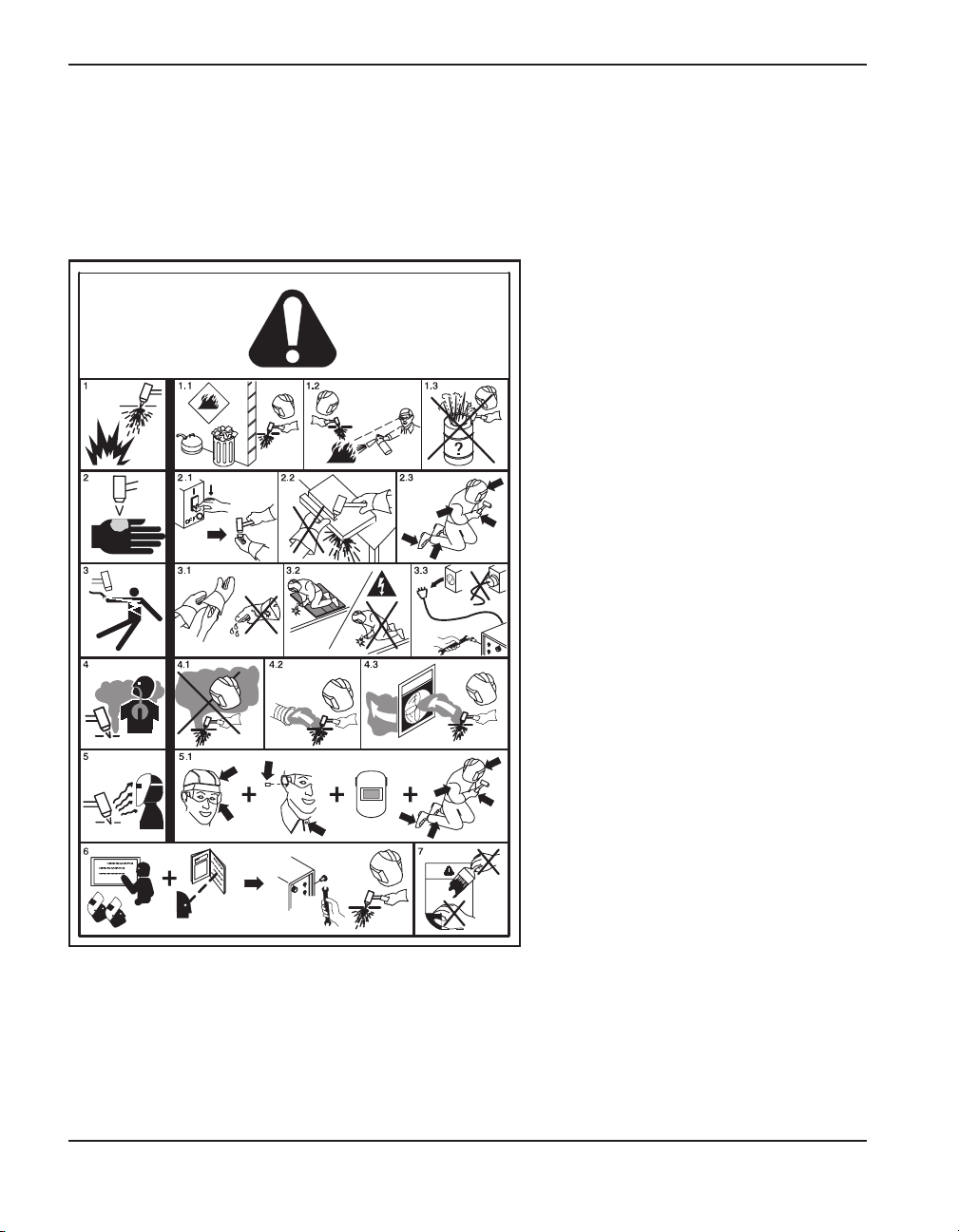
WARNING LABEL
This warning label is affixed to some power supplies. It is
important that the operator and maintenance technician
understand the intent of these warning symbols as described.
The numbered text corresponds to the numbered boxes on
the label.
1. Cutting sparks can cause explosion or
fire.
1.1 Keep flammables away from cutting.
1.2 Keep a fire extinguisher nearby, and
have a watchperson ready to use it.
1.3 Do not cut on any closed containers.
2. The plasma arc can cause injury and
burns.
2.1 Turn off power before disassembling
torch.
2.2 Do not hold the material near cutting
path.
2.3 Wear complete body protection.
3. Electric shock from torch or wiring can
kill. Protect yourself from electric shock.
3.1 Wear insulating gloves. Do not wear wet
or damaged gloves.
3.2 Insulate yourself from work and ground.
3.3 Disconnect input plug or power before
working on machine.
4. Breathing cutting fumes can be
hazardous to your health.
4.1 Keep your head out of the fumes.
4.2 Use forced ventilation or local exhaust
to remove the fumes.
4.3 Use ventilating fan to remove the fumes.
5. Arc rays can burn eyes and injure skin.
5.1 Wear hat and safety glasses. Use ear
protection and button shirt collar. Use
welding helmet with correct shade of
filter. Wear complete body protection.
6. Become trained and read the
instructions before working on the
machine or cutting.
7. Do not remove or paint over (cover)
warning labels.
1102 12
Page 14

2/12/01
Hypertherm Systèmes plasma 1a-1
Section 1a
SÉCURITÉ
Dans cette section :
Identifier les consignes de sécurité .........................................................................................................1a-2
Suivre les instructions de sécurité...........................................................................................................1a-2
Danger Avertissement Précaution.........................................................................................................1a-2
Le coupage peut provoquer un incendie ou une explosion.....................................................................1a-2
Prévention des incendies, Prévention des explosions ..................................................................1a-2
Risque d’explosion argon-hydrogène et méthane .........................................................................1a-2
Détonation de l’hydrogène lors du coupage de l’aluminium ..........................................................1a-2
Les chocs électriques peuvent être fatals ...............................................................................................1a-3
Prévention des chocs électriques..................................................................................................1a-3
Le coupage peut produire des vapeurs toxiques ....................................................................................1a-3
L’arc plasma peut provoquer des blessures ou des brûlures..................................................................1a-4
Torches à allumage instantané......................................................................................................1a-4
Les rayons de l’arc peuvent brûler les yeux et la peau ...........................................................................1a-4
Protection des yeux, Protection de la peau, Zone de coupage ...................................................1a-4
Mise à la masse et à la terre ...................................................................................................................1a-4
Câble de retour, Table de travail, Alimentation ..............................................................................1a-4
Sécurité des bouteilles de gaz comprimé ...............................................................................................1a-5
Les bouteilles de gaz comprimé peuvent exploser en cas de dommages..............................................1a-5
Le bruit peut provoquer des problèmes auditifs ......................................................................................1a-5
Pacemakers et prothèses auditives ........................................................................................................1a-5
Un arc plasma peut endommager les tuyaux gelés ................................................................................1a-5
Étiquette de sécurité ...............................................................................................................................1a-6
Page 15
SÉCURITÉ
2/12/01
1a-2 Hypertherm Systèmes plasma
IDENTIFIER LES CONSIGNES
DE SÉCURITÉ
Les symboles indiqués dans cette section sont utilisés
pour identifier les risques éventuels. Si vous trouvez un
symbole de sécurité, que ce soit dans ce manuel ou sur
l’équipement, soyez conscient des risques de blessures et
suivez les instructions correspondantes afin d’éviter ces
risques.
SUIVRE LES INSTRUCTIONS
DE SÉCURITÉ
Lire attentivement toutes les consignes de sécurité dans
le présent manuel et sur les étiquettes de sécurité se
trouvant sur la machine.
• Les étiquettes de sécurité doivent rester lisibles.
Remplacer immédiatement les étiquettes manquantes
ou abîmées.
• Apprendre à faire fonctionner la machine et à utiliser
correctement les commandes. Ne laisser personne
utiliser la machine sans connaître son fonctionnement.
• Garder la machine en bon état. Des modifications non
autorisées sur la machine peuvent engendrer des
problèmes de sécurité et raccourcir la durée d’utilisation
de l’équipement.
DANGER AVERTISSEMENT PRÉCAUTION
Les signaux DANGER ou AVERTISSEMENT sont utilisés
avec un symbole de sécurité, DANGER correspondant
aux risques les plus sérieux.
• Les étiquettes de sécurité DANGER et AVERTISSEMENT sont situées sur la machine pour signaler certains
dangers spécifiques.
• Les messages d’AVERTISSEMENT précèdent les
instructions d’utilisation expliquées dans ce manuel et
signalent les risques de blessures ou de mort au cas où
ces instructions ne seraient pas suivies correctement.
• Les messages de PRÉCAUTION précèdent les
instructions d’utilisation contenues dans ce manuel et
signalent que le matériel risque d’être endommagé si les
instructions ne sont pas suivies correctement.
Prévention des incendies
• Avant de commencer, s’assurer que la zone de coupage
ne présente aucun danger. Conserver un extincteur à
proximité.
• Éloigner toute matière inflammable à une distance d’au
moins 10 m du poste de coupage.
• Tremper le métal chaud ou le laisser refroidir avant de
le manipuler ou avant de le mettre en contact avec des
matériaux combustibles.
• Ne jamais couper des récipients pouvant contenir des
matières inflammables avant de les avoir vidés et
nettoyés correctement.
• Aérer toute atmosphère potentiellement inflammable
avant d’utiliser un système plasma.
• Lors de l’utilisation d’oxygène comme gaz plasma, un
système de ventilation par aspiration est nécessaire.
Prévention des explosions
• Ne pas couper en présence de poussière ou de
vapeurs.
• Ne pas couper de bouteilles, de tuyaux ou autres
récipients fermés et pressurisés.
• Ne pas couper de récipients contenant des matières
combustibles.
LE COUPAGE PEUT PROVOQUER UN INCENDIE
OU UNE EXPLOSION
AVERTISSEMENT
Risque d’explosion
argon-hydrogène et méthane
L’hydrogène et le méthane sont des gaz inflammables et
potentiellement explosifs. Conserver à l’écart de toute
flamme les bouteilles et tuyaux contenant des mélanges à
base d’hydrogène ou de méthane. Maintenir toute flamme
et étincelle à l’écart de la torche lors de l’utilisation d’un
plasma d’argon-hydrogène ou de méthane.
AVERTISSEMENT
Détonation de l’hydrogène lors du
coupage de l’aluminium
• Lors du coupage de l’aluminium sous l’eau, ou si l’eau
touche la partie inférieure de la pièce d’aluminium, de
l’hydrogène libre peut s’accumuler sous la pièce à
couper et détonner lors du coupage plasma.
• Installer un collecteur d’aération au fond de la table à eau
afin d’éliminer les risques de détonation de l’hydrogène.
Se référer à l’annexe du manuel pour plus de
renseignements sur les collecteurs d’aération.
Page 16
SÉCURITÉ
2/12/01
Hypertherm Systèmes plasma 1a-3
Toucher une pièce électrique sous tension peut provoquer
un choc électrique fatal ou des brûlures graves.
• La mise en fonctionnement du système plasma ferme un
circuit électrique entre la torche et la pièce à couper. La
pièce à couper et tout autre élément en contact avec cette
pièce font partie du circuit électrique.
• Ne jamais toucher le corps de la torche, la pièce à couper
ou l’eau de la table à eau pendant le fonctionnement du
système plasma.
Prévention des chocs électriques
Tous les systèmes plasma Hypertherm utilisent des
hautes tensions pour le coupage (souvent de 200 à 400
V). On doit prendre les précautions suivantes quand on
utilise le système plasma :
• Porter des bottes et des gants isolants et garder le corps
et les vêtements au sec.
• Ne pas se tenir, s’asseoir ou se coucher sur une surface
mouillée, ni la toucher quand on utilise le système plasma.
• S’isoler de la surface de travail et du sol en utilisant des
tapis isolants secs ou des couvertures assez grandes
pour éviter tout contact physique avec le travail ou le sol.
S’il s’avère nécessaire de travailler dans ou près d’un
endroit humide, procéder avec une extrême prudence.
• Installer un sectionneur avec fusibles appropriés, à
proximité de la source de courant. Ce dispositif permet à
l’opérateur d’arrêter rapidement la source de courant en
cas d’urgence.
• En cas d’utilisation d’une table à eau, s’assurer que cette
dernière est correctement mise à la terre.
LES CHOCS ÉLECTRIQUES PEUVENT ÊTRE FATALS
• Installer et mettre à la terre l’équipement selon les
instructions du présent manuel et conformément aux
codes électriques locaux et nationaux.
• Inspecter fréquemment le cordon d’alimentation primaire
pour s’assurer qu’il n’est ni endommagé, ni fendu.
Remplacer immédiatement un cordon endommagé.
Un câble dénudé peut tuer.
• Inspecter et remplacer les câbles de la torche qui sont
usés ou endommagés.
• Ne pas saisir la pièce à couper ni les chutes lors du
coupage. Laisser la pièce à couper en place ou sur la
table de travail, le câble de retour connecté lors du
coupage.
• Avant de vérifier, de nettoyer ou de remplacer les pièces
de la torche, couper l’alimentation ou débrancher la prise
de courant.
• Ne jamais contourner ou court-circuiter les verrouillages
de sécurité.
• Avant d’enlever le capot du système ou de la source de
courant, couper l’alimentation électrique. Attendre en
suite
5 minutes pour que les condensateurs se déchargent.
• Ne jamais faire fonctionner le système plasma sans que
les capots de la source de courant ne soient en place.
Les raccords exposés de la source de courant sont
extrêmement dangereux.
• Lors de l’installation des connexions, attacher tout d’abord
la prise de terre appropriée.
• Chaque système plasma Hypertherm est conçu pour être
utilisé uniquement avec des torches Hypertherm
spécifiques. Ne pas utiliser des torches inappropriées qui
pourraient surchauffer et présenter des risques pour la
sécurité.
Le coupage peut produire des vapeurs et des gaz toxiques
qui réduisent le niveau d’oxygène dans l’air et peuvent
provoquer des blessures, voire la mort.
• Conserver le poste de coupage bien aéré ou utiliser un
masque respiratoire homologué.
• Ne pas procéder au coupage près d’endroits où
s’effectuent le dégraissage, le nettoyage ou la vaporisation. Certains solvants chlorés se décomposent sous
l’effet des rayons ultraviolets et forment du phosgène.
• Ne pas couper des métaux peints ou contenant des
matières toxiques comme le zinc (galvanisé), le plomb, le
cadmium ou le béryllium, à moins que la zone de travail
LE COUPAGE PEUT PRODUIRE DES VAPEURS TOXIQUES
soit très bien ventilée et que l’opérateur porte un masque
respiratoire. Les revêtements et métaux contenant ces
matières peuvent produire des vapeurs toxiques lors du
coupage.
• Ne jamais couper de récipients pouvant contenir des
matières inflammables avant de les avoir vidés et
nettoyés correctement.
• Quand on utilise ce produit pour le soudage ou le
coupage, il dégage des fumées et des gaz qui
contiennent des produits chimiques qui, selon l’État de
Californie, provoquent des anomalies congénitales et,
dans certains cas, le cancer.
Page 17
SÉCURITÉ
5/6/02
1a-4 Hypertherm Systèmes plasma
Torches à allumage instantané
L’arc plasma s’allume immédiatement après que la torche
soit mise en marche.
L’ARC PLASMA PEUT PROVOQUER DES BLESSURES OU DES BRÛLURES
L’arc plasma coupe facilement les gants et la peau.
• Rester éloigné de l’extrémité de la torche.
• Ne pas tenir de métal près de la trajectoire de coupe.
• Ne jamais pointer la torche vers soi ou d’autres
personnes.
Câble de retour Bien fixer le câble de retour (ou de
masse) à la pièce à couper ou à la table de travail de
façon à assurer un bon contact métal-métal. Ne pas fixer
le câble de retour à la partie de la pièce qui doit se
détacher.
Table de travail Raccorder la table de travail à la terre,
conformément aux codes de sécurité locaux ou nationaux
appropriés.
MISE À LA MASSE ET À LA TERRE
Alimentation
• S’assurer que le fil de terre du cordon d’alimentation est
connecté à la terre dans le coffret du sectionneur.
• S’il est nécessaire de brancher le cordon d’alimentation
à la source de courant lors de l’installation du système,
s’assurer que le fil de terre est correctement branché.
• Placer tout d’abord le fil de terre du cordon
d’alimentation sur le plot de mise à la terre puis placer
les autres fils de terre par-dessus. Bien serrer l’écrou de
retenue.
• S’assurer que toutes les connexions sont bien serrées
pour éviter la surchauffe.
Protection des yeux Les rayons de l’arc plasma
produisent de puissants rayons visibles ou invisibles
(ultraviolets et infrarouges) qui peuvent brûler les yeux et
la peau.
• Utiliser des lunettes de sécurité conformément aux
codes locaux ou nationaux en vigueur.
• Porter des lunettes de protection (lunettes ou masque
muni d’écrans latéraux et encore masque de soudure)
avec des verres teintés appropriés pour protéger les
yeux des rayons ultraviolets et infrarouges de l’arc.
Puissance des verres teintés
Courant de l’arc AWS (É.-U.) ISO 4850
Jusqu’à 100 A N
o
8N
o
11
100-200 A N
o
10 No11-12
200-400 A N
o
12 No13
Plus de 400 A N
o
14 No14
LES RAYONS DE L’ARC PEUVENT BRÛLER LES YEUX ET LA PEAU
Protection de la peau Porter des vêtements de sécurité
pour se protéger contre les brûlures que peuvent causer
les rayons ultraviolets, les étincelles et le métal brûlant :
• Gants à crispin, chaussures et casque de sécurité.
• Vêtements ignifuges couvrant toutes les parties
exposées du corps.
• Pantalon sans revers pour éviter que des étincelles ou
des scories puissent s’y loger.
• Avant le coupage, retirer de ses poches tout objet
combustible comme les briquets au butane ou les
allumettes.
Zone de coupage Préparer la zone de coupage afin de
réduire la réverbération et la transmission de la lumière
ultraviolette :
• Peindre les murs et autres surfaces de couleur sombre
pour réduire la réflexion de la lumière.
• Utiliser des écrans et autres dispositifs de protection afin
de protéger les autres personnes de la lumière et de la
réverbération.
• Prévenir les autres personnes de ne pas regarder l’arc.
Utiliser des affiches ou des panneaux.
Page 18
SÉCURITÉ
2/12/01
Hypertherm Systèmes plasma 1a-5
• Ne jamais lubrifier les robinets des bouteilles ou les
régulateurs avec de l’huile ou de la graisse.
• Utiliser uniquement les bouteilles, régulateurs, tuyaux et
accessoires appropriés et conçus pour chaque
application spécifique.
• Entretenir l’équipement et les pièces d’équipement à gaz
comprimé afin de les garder en bon état.
• Étiqueter et coder avec des couleurs tous les tuyaux de
gaz afin d’identifier le type de gaz contenu dans chaque
tuyau. Se référer aux codes locaux ou nationaux en
vigueur.
LES BOUTEILLES DE GAZ
COMPRIMÉ PEUVENT EXPLOSER
EN CAS DE DOMMAGES
SÉCURITÉ DES BOUTEILLES DE
GAZ COMPRIMÉ
Les bouteilles de gaz contiennent du gaz à haute pression.
Si une bouteille est endommagée, elle peut exploser.
• Manipuler et utiliser les bouteilles de gaz comprimé
conformément aux codes locaux ou nationaux.
• Ne jamais utiliser une bouteille qui n’est pas placée à la
verticale et bien assujettie.
• Le capuchon de protection doit être placé sur le robinet
sauf si la bouteille est en cours d’utilisation ou connectée
pour utilisation.
• Éviter à tout prix le contact électrique entre l’arc plasma et
une bouteille.
• Ne jamais exposer des bouteilles à une chaleur
excessive, aux étincelles, aux scories ou aux flammes
nues.
• Ne jamais utiliser des marteaux, des clés ou d’autres
outils pour débloquer le robinet des bouteilles.
Une exposition prolongée au bruit du coupage ou du
gougeage peut provoquer des problèmes auditifs.
• Utiliser un casque de protection homologué lors de
l’utilisation du système plasma.
• Prévenir les personnes aux alentours des risques
encourus en cas d’exposition au bruit.
Les tuyaux gelés peuvent être endommagés ou éclater si
l'on essaie de les dégeler avec une torche plasma.
LE BRUIT PEUT PROVOQUER DES
PROBLÈMES AUDITIFS
UN ARC PLASMA
PEUT ENDOMMAGER LES
TUYAUX GELÉS
Les champs magnétiques produits par les courants à
haute tension peuvent affecter le fonctionnement des
prothèses auditives et des pacemakers. Les personnes
portant ce type d’appareil doivent consulter un médecin
avant de s’approcher d’un lieu où s’effectue le coupage
ou le gougeage plasma.
Pour réduire les risques associés aux champs
magnétiques :
• Garder loin de soi et du même côté du corps le câble
de retour et le faisceau de la torche.
• Faire passer le faisceau de la torche le plus près
possible du câble de retour.
• Ne pas s’enrouler le faisceau de la torche ou le câble
de retour autour du corps.
• Se tenir le plus loin possible de la source de courant.
PACEMAKERS ET
PROTHÈSES AUDITIVES
Page 19
SÉCURITÉ
2/12/01
1a-6 Hypertherm Systèmes plasma
Étiquette de sécurité
Cette étiquette est affichée sur la source de courant. Il est important
que l’utilisateur et le technicien de maintenance comprennent la
signification des symboles de sécurité. Les numéros de la liste
correspondent aux numéros des images.
1. Les étincelles produites par le coupage
peuvent provoquer une explosion ou un
incendie.
1.1 Pendant le coupage, éloigner toute matière
inflammable.
1.2 Conserver un extincteur à proximité et
s’assurer qu’une personne soit prête à l’utiliser.
1.3 Ne jamais couper de récipients fermés.
2. L’arc plasma peut provoquer des blessures et
des brûlures.
2.1 Couper l’alimentation avant de démonter la
torche.
2.2 Ne pas tenir la surface à couper près de la
trajectoire de coupe.
2.3 Porter des vêtements de protection couvrant
tout le corps.
3. Un choc électrique causé par la torche ou les
câbles peut être fatal. Se protéger contre les
risques de chocs électriques.
3.1 Porter des gants isolants. Ne pas porter de
gants mouillés ou abîmés.
3.2 S’isoler de la surface de travail et du sol.
3.3 Débrancher la prise ou la source de courant
avant de manipuler l’équipement.
4. L’inhalation des vapeurs produites par le
coupage peut être dangereuse pour la santé.
4.1 Garder le visage à l’écart des vapeurs.
4.2 Utiliser un système de ventilation par aspiration
ou d’échappement localisé pour dissiper les
vapeurs.
4.3 Utiliser un ventilateur pour dissiper les vapeurs.
5. Les rayons de l’arc peuvent brûler les yeux et
provoquer des lésions de la peau.
5.1 Porter un casque et des lunettes de sécurité.
Se protéger les oreilles et porter une chemise
dont le col peut être déboutonné. Porter un
casque de soudure dont la protection filtrante
est suffisante. Porter des vêtements
protecteurs couvrant la totalité du corps.
6. Se former à la technique du coupage et lire les
instructions avant de manipuler l’équipement
ou de procéder au coupage.
7. Ne pas retirer ou peindre (recouvrir) les
étiquettes de sécurité.
110212
Page 20

powermax600
Operator Manual 2-1
0
Section 2
SPECIFICATIONS
In this section:
Specifications, Power Supply ..................................................................................................................................2-2
Specifications, PAC123 Torches ..............................................................................................................................2-3
Symbols and Markings .............................................................................................................................................2-4
Page 21
2-2 powermax600 Operator Manual
SPECIFICATIONS
0
Specifications, Power Supply
Rated Open Circuit Voltage (U0) 300 VDC
Rated Output Current (I2) 20 A – 40 A
Rated Output Voltage (U2) 140 VDC
Duty Cycle at 40°C 50 % (I2=40 A, U2=140 V)
(See data tag on power supply for 100 % (I2=28 A, U2=140 V
more information on duty cycle.)
Operating temperature -10° to +40°C (+14° to 104° F)
Apparent Input Power (S1) 230/400 V = 6.7 kVA
208-240/480 V = 9.5 kVA
Input Voltage (U1)/ Input Current (I1) at 230 V/17 A – 3-phase, 50/60 Hz CE
5.6 kW Output 400 V/9,7 A – 3-phase, 50/60 Hz CE
208-240 V/40-46 A – 1-phase, 50/60 Hz CSA/NRTL
480 V/12 A – 3-phase, 50/60 Hz CSA/NRTL
Gas Type Air Nitrogen
Gas Quality Clean, dry, oil-free 99.995 % pure
Gas Inlet Pressure and Flow See Section 3, Setup
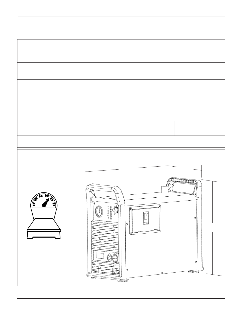
PMX600.14
Powermax600 Power Supply Dimensions and Weight
20 in
510 mm
9.5 in
240 mm
17 in
430 mm
Weight with hand torch
and 15 ft / 4.5 m lead.
47 lb
21 kg
Page 22

SPECIFICATIONS
powermax600
Operator Manual 2-3
0
Specifications PAC123 Torches
Maximum Cutting Capacity
40A PAC123T 5/8 inch / 16 mm @ 50 % duty cycle
40A PAC123M 1/4 inch / 6 mm @ 50 % duty cycle
28A PAC123M 1/8 inch / 3 mm @ 100 % duty cycle
Gouging Capability 5.6 pounds / 2.5 kg
(metal removal rate) hour
Weight
3.5 pounds / 1.6 kg with 15 ft / 4.5 m lead
PAC123T 4.5 pounds / 2 kg with 25 ft / 7.5 m lead
7 pounds / 3.2 kg with 50 ft / 15 m lead
6 pounds / 2.7 kg with 15 ft / 4.5 m lead
PAC123M 7 pounds / 3.2 kg with 25 ft / 7.5 m lead
9.5 pounds / 4.3 kg with 50 ft / 15 m lead
PAC123T Hand Torch Dimensions
PAC123M Machine Torch Dimensions
PAC123T
PAC123T.04
PAC123M.07
8.72" / 221 mm
8.5" / 216 mm
15.06"
383 mm
3.10"
79 mm
1.58"
40 mm
1.00"
25 mm
1.38"
35 mm
1.00"
25 mm
Page 23

2-4 powermax600 Operator Manual
SPECIFICATIONS
0
O
l
Symbols and Markings
S
MARK (230/400 Volt only)
The S mark indicates that the power supply and torch are suitable for use in environments with increased hazard
of electrical shock. The hand torches must have shielded consumable parts to maintain S mark compliance.
IEC Symbols Used
The following symbols may appear on the power supply data plate, control labels and switches.
Direct Current (DC)
The terminal for the external
protective (earth) conductor
AC input power connection
Plasma torch cutting
and gouging
Alternating current (AC)
An inverter-based power source
Volt/amp curve, "drooping"
characteristic
Power is off
Power is on
Plasma torch in the TEST
position (cooling and cutting
gas exiting nozzle)
Page 24

powermax600
Operator Manual 3-1
Section 3
SETUP
In this section:
Lifting Power Supply .................................................................................................................................................3-2
Power Hookup ..........................................................................................................................................................3-2
Torch Hookup (Quick Disconnect Only)....................................................................................................................3-5
Gas Hookup..............................................................................................................................................................3-5
PAC123M Machine Torch Setup...............................................................................................................................3-7
Page 25

SETUP
3-2 powermax600 Operator Manual
Lifting Power Supply
WARNING
The power supply weighs up to 54 lb / 25 kg. Do not lift the power supply by ONE handle. The
handle can break, resulting in injury and damage to the power supply.
Power Hookup
Check Required Input Voltage
Look at U1 on the data plate to check input voltage requirements.
The data plate is on the back of the power supply.
54 lb
25 kg
Hoist
Cover in place
Approved
hoisting strap.
Keep as vertical
as possible
Page 26

SETUP
powermax600
Operator Manual 3-3
Power Hookup (Continued)
Install Power Cord Plug
Use a power cord plug that is certified by national or local
electrical codes. The plug should be connected to the
power cord by a licensed electrician.
Extension Cord
Use a cord that is certified by national or local codes. The cord should be installed by a licensed electrician. Refer
to the length requirements listed below.
< 10 ft 10-25 ft 25-50 ft 50-100 ft 100-150 ft
< 3 m 3 – 7.5 m 7.5 – 15 m 15 – 30 m 30 – 45 m
InputVoltage Phase Recommended Cord Gauge Size (mm
2
)
208-240 VAC 1 10 10 10 16 16
230 VAC 3 4 6 6 10 10
400 VAC 3 2.5 2.5 4 6 6
480 VAC 3 4 4 4 4 6
Recommended Cord Gauge Size (AWG)
208-240 VAC 1 8 8 8 6 6
230 VAC 3 12 10 10 8 8
400 VAC 3 14 14 12 10 10
480 VAC 3 12 12 12 12 10
C
O
M
P
.0
1
A
PMX600.02
Page 27

SETUP
3-4 powermax600 Operator Manual
Line Voltage Disconnect Box
Use a line disconnect box for each power supply so that the operator can turn the power supply off quickly in an
emergency situation. Locate the switch near the power supply so that it is easily accessible to the operator. The
interrupt level of the switch must be equal to or exceed the continuous rating of the fuses. Use slow-blow fuses as
listed below.
Grounding Requirements
To ensure personal safety, proper operation and to reduce electromagnetic interference (EMI), the
Powermax600 must be properly grounded:
• The power supply chassis is electrically conductive and can present a shock hazard if it is not properly
grounded through the line voltage disconnect box.
• The power supply must be properly grounded through the power cord according to national or local
electrical codes.
• Three-phase service must use a 4-wire cord that includes a protective earth ground.
• Also see Grounding Safety, in Section 1 of this manual.
Generator Power
When using a generator to power the Powermax600:
• Use a generator with a minimum auxiliary output of 8 kVA.
• The generator must be dedicated to powering the plasma cutting system.
• Generator Operation:
1. Set the generator output to AC.
2. Plug the Powermax600 power cord into the auxiliary power outlet.
3. Set the generator to the appropriate output range. If the Powermax600 circuit breaker will not
stay on, reduce the generator output.
• Use unshielded consumables if you experience difficulty with thicker material cutting (non-CE
systems only).
Input Input Current Recommended
Voltage Phase @ 5.6 kw Output Slow-Blow Fuse Size
208-240 VAC 1 46-40 A 100 A
230 VAC 3 17 A 40 A
400 VAC 3 9.7 A 25 A
480 VAC 3 12 A 25 A
PMX600.03
P
M
X600.04
Page 28

SETUP
powermax600
Operator Manual 3-5
Minimum Gas Inlet Pressure 90 psi / 6.2 bar
Gas Flow 6 scfm @ 90 psi / 170 l/min @ 6.2 bar
Gas Hookup
Gas Requirements
Air must be filtered to remove all dirt, water and oil. Contaminants can damage the power supply, torch
and consummables.
The power supply will not power-up if the gas inlet pressure is below minimum.
CAUTION: Do not exceed 120 psi / 8.3 bar pressure at the power supply gas inlet.
Damage to system may result from higher pressures.
Torch Hookup (For models with quick disconnect)
Install torch lead to power supply.
PMX600.06
Key-way
Before tightening, align threads by
turning one turn counterclockwise.
Page 29

3-6
SETUP
powermax600 Operator Manual
Gas Supply Connection
•
Use an inert gas hose to connect the gas supply (air or nitrogen) to the power supply gas inlet.
• Apply liquid pipe sealant to the threads to ensure a leak-free installation.
CAUTION: Do not use PTFE tape on pipe threads. Pieces of tape
can enter the air line and damage the system.
Shipped with these
parts installed.
10-99
208-240/480V
90 psi / 6.2 bar
230/400V
90 psi / 6.2 bar
PMX600.11
Page 30

SETUP
powermax600
Operator Manual 3-7
P
A
C
123M
.06
Pigtail from Machine
Torch Lead
On/Off Pendant
PAC123M ON/OFF Pendant Connection
PAC123M Torch Alignment
Mount the machine torch perpendicular to the workpiece in order to
get a vertical cut. Use a square to align the torch at 0° and 90°.
PAC123M Machine Torch Setup
Socket A White Wire
Socket B Not Used
Socket C Black Wire
Torch
0°
90°
Page 31

SETUP
3-8 powermax600 Operator Manual
Page 32

powermax600
Operator Manual 4-1
10-99
Section 4
OPERATION
In this section:
Controls and Indicators.............................................................................................................................................4-2
Confirm Torch Consumables.....................................................................................................................................4-3
installing Torch Consumables ...................................................................................................................................4-4
Pilot Arc ControlSswitch (208-240/480 Volt Only).....................................................................................................4-5
Turn On Power..........................................................................................................................................................4-5
Check Indicator Lights ..............................................................................................................................................4-5
Adjust Gas Pressure and Current Setting.................................................................................................................4-6
Hand Torch Operation...............................................................................................................................................4-7
Machine Torch Operation........................................................................................................................................4-12
Cut Chart ................................................................................................................................................................4-12
Page 33

OPERATION
10-99
4-2 powermax600 Operator Manual
PMX600.05
ON
OFF
Controls and Indicators
Current
(Amps)
Adjustment
Knob
Indicator Lamps
Pressure
Gauge
Power Lamp
See
Section 5
Ready Lamp
ON (I)/OFF (0)
Switch
Pressure
Regulator
Pilot Arc
Control Switch
(208-240,480 V)
Page 34

OPERATION
10-99
powermax600
Operator Manual 4-3
Confirm Torch Consumables
Machine
Cutting
Unshielded *
120827 120600 120826
Deflector
120574
120303 120600 120606
Hand
Cutting
Gouging
120828 120600 120826
Shield Retaining Cap Nozzle
120573
120576
Electrode Swirl Ring
120608 120600 120831
* In CE countries, unshielded consumables may only be used in machine-torch applications.
Page 35

OPERATION
10-99
4-4 powermax600 Operator Manual
WARNING
INSTANT-ON TORCHES
PLASMA ARC CAN CAUSE INJURY AND BURNS
Plasma arc comes on immediately when the torch switch is activated.
The plasma arc will quickly cut through gloves and skin.
Make sure power is off before changing consumables.
Installing Torch Consumables
Hand tighten only.
Hand tighten only.
Page 36

OPERATION
10-99
powermax600
Operator Manual 4-5
Turn On Power
Position the power switch to ON.
Check that the POWER ON lamp is illuminated.
Check Indicator Lights
Check that the remaining indicator lamps are NOT illuminated.
See Section 5 for details.
PMX600.07A
Pilot Arc Control Switch (208-240/480 Volt Only)
Use to cut expanded metal.
Automatically reinitiates pilot.
Use to cut plate/sheet metal.
Optimum consumable life.
Check that the OK lamp is illuminated.
Page 37

OPERATION
10-99
4-6 powermax600 Operator Manual
Turn the current adjustment knob to the gas test setting.
40
Push the knob down to
lock the regulator.
• Look at the pressure gauge
and check that the correct gas
pressure is set.
• If the correct gas pressure is
set, proceed to .
• If the gas pressure requires
adjustment, proceed to .
Adjust Gas Pressure and Current Setting
Pull the regulator knob up to unlock.
Turn the regulator knob to obtain the correct pressure.
Turn the current
adjustment knob to
the desired amps
setting.
40
15 ft
4.5 m
50 ft
15 m
25 ft
7.5 m
72 psi
5.0 BAR
72 psi
5.0 BAR
78 psi
5.4 BAR
60 psi
4.2 BAR
55 psi
3.8 BAR
50 psi
3.4 BAR
PMX600.18
Lead Length
Page 38

OPERATION
10-99
powermax600
Operator Manual 4-7
Hand Torch Operation
WARNING
INSTANT-ON TORCHES
PLASMA ARC CAN CAUSE INJURY AND BURNS
Plasma arc comes on immediately when the torch switch is activated.
The plasma arc will quickly cut through gloves and skin.
• Keep away from the torch tip.
• Do not hold the workpiece, and keep your hands clear of the cutting path.
• Never point the torch toward yourself or others.
Safety Trigger Operation
Avoid firing the torch when it is
not in contact with the workpiece.
Page 39

OPERATION
10-99
4-8 powermax600 Operator Manual
Hand Torch Cutting Technique
Firing the torch unnecessarily
reduces nozzle and electrode life.
When cutting, make sure that sparks are exiting from
the bottom of the workpiece.
If sparks are spraying up from the workpiece, you are
moving the torch too fast, or without sufficient power.
Hold the torch nozzle at a vertical position and watch
the arc as it cuts along the line.
Shielded Consumables. Do not push down on the
torch when cutting. Lightly drag the torch across the
workpiece to maintain a steady cut.
• Pulling the torch through the cut is easier than pushing it.
• To cut thin material, reduce the amps until you get the best
quality cut.
• For straight-line cuts, use a straight edge as a guide. To cut
circles, use a template or a radius cutter attachment.
Unshielded Consumables. Maintain an approximate
1/16 inch / 1.5 mm torch-to-work distance.
Page 40

OPERATION
10-99
powermax600
Operator Manual 4-9
Attach the work clamp securely to the
workpiece. Remove rust, paint or other
coatings to ensure good electrical contact.
Attach the work clamp as close as possible
to the area being cut, to reduce exposure to
electromagnetic fields (EMF).
Do not attach it to the portion that will fall
away.
Starting a Cut from the
Edge of the Workpiece
Hold the torch nozzle vertical at
the edge of the workpiece.
Start cutting from the edge of the
workpiece.
Pause at the edge until the arc has
completely cut through the
workpiece.
Then, proceed with the cut.
Attach the Work Clamp
Page 41

OPERATION
10-99
4-10 powermax600 Operator Manual
WARNING
SPARKS AND HOT METAL CAN INJURE
EYES AND BURN SKIN
When firing the torch at an angle, sparks and hot metal will spray out from
the nozzle. Point the torch away from yourself and others.
Piercing
Hold the torch so that the nozzle is within 1/16 inch / 1.5 mm from the workpiece before firing the torch.
Fire the torch at an angle to the
workpiece, then slowly rotate it to an
upright position.
When sparks are exiting from the
bottom of the workpiece, the arc has
pierced through the material.
When the pierce is complete, proceed
with the cut.
Page 42

OPERATION
10-99
powermax600
Operator Manual 4-11
Gouging
Hold the torch perpendicular to the workpiece.
Pull the trigger to transfer the arc.
Rotate the torch to 45° from the workpiece.
Feed into the gouge.
WARNING
SPARKS AND HOT METAL CAN INJURE
EYES AND BURN SKIN
When firing the torch at an angle, sparks and hot metal will spray out from
the nozzle. Point the torch away from yourself and others.
Direction of travel
45°
Page 43

OPERATION
10-99
4-12 powermax600 Operator Manual
Machine Torch Operation
Cut Chart - 40 Amp Standard Consumables
• The following recommended settings are for mechanized cutting.
• Torch-to-work distance for the following cut chart is 1/16 inch / 1.5 mm for all cuts.
Shield
120827
Retaining Cap
120600
Nozzle
120826
Electrode
120573
Swirl Ring
120576
PAC123
Torch
Material Thickness Arc Arc Recommended Travel Speed Pierce
Material Current Voltage Delay
(ga. or in.) (mm) (A) (VDC) (ipm) (mm/min.) (Sec.)
26 ga. 0.5 Mild Steel 20 155 250 6850 0
16 ga. 1.5 Mild Steel 20 155 385 1780 0
16 ga. 1.5 Mild Steel 40 120 370 10150 0
1/8" 3 Mild Steel 40 120 140 4950 0.5
1/4" 6 Mild Steel 40 130 55 1680 1.0
3/8" 10 Mild Steel 40 140 27 640 †
1/2" 13 Mild Steel 40 140 19 460 †
5/8" 16 Mild Steel 40 150 10 250 †
0.020" 1 Aluminum 20 170 175 4150 0
0.060" 1.5 Aluminum 20 170 125 3330 0
16 ga. 1.5 Aluminum 40 130 420 10900 0
1/8" 3 Aluminum 40 135 140 4450 0.5
1/4" 6 Aluminum 40 140 53 1620 1.0
3/8" 10 Aluminum 40 150 25 510 †
1/2" 13 Aluminum 40 150 17 410 †
5/8" 16 Aluminum 40 160 8 200 †
26 ga. 0.5 Stainless Steel 20 160 235 5970 0
16 ga. 1.5 Stainless Steel 20 160 50 1270 0
16 ga. 1.5 Stainless Steel 40 130 400 10150 0
1/8" 3 Stainless Steel 40 140 105 4060 0.5
1/4" 6 Stainless Steel 40 140 44 1320 1,0
3/8" 10 Stainless Steel 40 140 21 510 †
1/2" 13 Stainless Steel 40 150 14 330 †
5/8" 16 Stainless Steel 40 160 7 180 †
† To cut material above 6 mm, start torch at edge of material.
Page 44

powermax600
Operator Manual 5-1
10-99
Section 5
MAINTENANCE AND PARTS
In this section:
Routine Maintenance................................................................................................................................................5-2
Inspect Consumables ...............................................................................................................................................5-3
Torch Lead Replacement..........................................................................................................................................5-5
Work Cable Replacement.........................................................................................................................................5-6
Power Cord Replacement.........................................................................................................................................5-7
Air Filter Element Replacement ................................................................................................................................5-8
Basic Troubleshooting ............................................................................................................................................5-10
Technical Questions................................................................................................................................................5-10
Parts .......................................................................................................................................................................5-14
Torch Consumables ........................................................................................................................See Section 4
PAC123T Hand Torch Assembly (No Quick Disconnect) ...............................................................................5-14
PAC123T Hand Torch Assembly (With Quick Disconnect).............................................................................5-16
PAC123M Machine Torch Assembly (No Quick Disconnect) .........................................................................5-18
PAC123M Machine Torch Assembly (With Quick Disconnect).......................................................................5-20
Power Supply - Filter Regulator .....................................................................................................................5-22
Power Supply - Work Cable ...........................................................................................................................5-22
Powermax600 Labels.....................................................................................................................................5-23
Powermax600 Field Upgrade Kits and Optional Parts...................................................................................5-23
Page 45

MAINTENANCE AND PARTS
10-99
5-2 powermax600 Operator Manual
Routine Maintenance
WARNING
ELECTRIC SHOCK CAN KILL
Disconnect electrical power before performing any maintenance.
All work requiring removal of the power supply cover must be
performed by a qualified technician.
Each Use
Check gas pressure.
Replace damaged power
cord or plug.
Replace damaged
torch lead.
Check pressure hose and
connections for leaks.
Clean the inside of the
power supply with air
pressure or vacuum.
Replace damaged labels.
Check torch cap-on safety switch: listen for
"click" when the retaining cap is loosened.
Check consumables for proper
installation and wear.
Check trigger for damage. Check torch body
for cracks and exposed conductors.
Each Week
6 Months
3 Months
Page 46

MAINTENANCE AND PARTS
10-99
powermax600
Operator Manual 5-3
Inspect Consumables
Missing
Castellation
Shield
Wear of castellations Castellations must not be
worn off.
Replace
Edge gas holes Blocked holes None Clear by pushing a pin
through blocked hole from
the inside
Center hole Round Hole must be round Replace
Signs of arcing None Replace
Nozzle tip
Nozzle
Even wear or erosion
1/32 inch /
1 mm
minimum
remaining
Replace
Side wear or erosion None Replace
Center hole Round
(View from inside)
Hole must be round Replace
Center surface
Electrode
Wear Pit not more than
1/16 inch / 1.6 mm deep
Replace
o o
Max. 1.6 mm
External surfaces
Part Check For Limit Action
Page 47

MAINTENANCE AND PARTS
10-99
5-4 powermax600 Operator Manual
Inspect Consumables (Continued)
External surfaces
Damage or debris Clean and no damage Replace
Edge gas holes Blocked holes None Replace
External surfaces
Damage or wear None Replace
Lubricated Not dry Apply a thin film of silicone
lubricant.
Part Check For Limit Action
Swirl Ring
Torch O-ring
Page 48

MAINTENANCE AND PARTS
10-99
powermax600
Operator Manual 5-5
WARNING
ELECTRIC SHOCK CAN KILL
Disconnect electrical power before performing any maintenance.
All work requiring removal of the power supply cover must be
performed by a qualified technician.
Torch Lead Replacement (For Models Without Quick Disconnect)
Disconnect electrical power and gas supply before removing the old torch lead.
Installation
CAUTION: Do not tighten the strain relief collar (4) onto the torch lead until
the gas fitting (3) is tight, or the gas connection may leak.
1. Install the strain relief (1) and secure with nut (2).
2. Connect and tighten the gas fitting (3).
3. Tighten the strain relief collar (4) onto the lead.
4. Connect the electrical connections (5), (6) and (7).
Tighten the terminal block screws to 10 in-lb /
12 kg cm of torque.
5. Install the power supply cover.
6. Reconnect electrical power and gas supply.
CAUTION: This is a high current connection.
Proper torque is critical.
Page 49

MAINTENANCE AND PARTS
10-99
5-6 powermax600 Operator Manual
Disconnect electrical power and gas supply before removing the old work cable.
Installation
1. Install the strain relief (1) to the power supply and secure with nut (2).
2. Install the work cable (3) through the strain relief.
3. Tie a knot (4) in the end of the work cable.
4. Tighten the strain relief collar (5) onto the cable.
5. Connect the work cable to the terminal block (6).
Tighten the terminal block screw to 10 in-lb / 12 kg cm of torque.
6. Install the power supply cover. Reconnect electrical power and gas supply.
Work Cable Replacement
CAUTION: This is a high current connection.
Proper torque is critical.
PMX600.15
WARNING
ELECTRIC SHOCK CAN KILL
Disconnect electrical power before performing any maintenance.
All work requiring removal of the power supply cover must be
performed by a qualified technician.
Page 50

MAINTENANCE AND PARTS
10-99
powermax600
Operator Manual 5-7
Power Cord Replacement
Disconnect electrical power and gas supply before removing the old power cord.
Installation
1. Insert the new power cord through the strain relief.
2. Pass all 4 wires through the toroid, as shown (230 and 400 volt only).
3. Install the power cord connections where shown.
4. Tighten the strain relief onto the power cord.
5. Install the power supply cover.
6. Reconnect electrical power and gas supply.
208V - 240V
230V and 400V
PMX600.12
480V
230V 400V
YELLOW
GREEN
GREEN
BROWN BLUE BLACK
BLACK WHITE
GREEN
BLACK WHITE RED
Pass all 4 wires through
the toroid 2 times.
Pass all 4 wires through
the toroid 3 times.
NOTE: Toroid must be installed for
power supply to be in compliance
with EMC standard EN50199.
WARNING
ELECTRIC SHOCK CAN KILL
Disconnect electrical power before performing any maintenance.
All work requiring removal of the power supply cover must be
performed by a qualified technician.
Page 51

MAINTENANCE AND PARTS
10-99
5-8 powermax600 Operator Manual
Air Filter Element Replacement
Compress the hose fitting collar and
pull the gas hose from the hose fitting.
Pull the drain hose from the grommet
in the floor of the power supply.
Unscrew the filter bowl. Do not
discard the O-ring.
Remove the filter element from
the filter housing.
NOTE: Do not allow the filter element to turn
when loosening the screw.
Removal
• Disconnect electrical power.
• Disconnect gas supply.
• Remove the power supply cover.
WARNING
ELECTRIC SHOCK CAN KILL
Disconnect electrical power before performing any maintenance.
All work requiring removal of the power supply cover must be
performed by a qualified technician.
Page 52

MAINTENANCE AND PARTS
10-99
powermax600
Operator Manual 5-9
Air Filter Element Replacement (continued)
Push the pressure line fully into the hose fitting.
Install the drain hose into the grommet.
• Install the power supply cover.
• Reconnect electrical power and gas supply.
Install the new filter element into the filter housing.
Secure with screw and retainer.
Install the filter bowl and O-ring into the filter housing.
Installation
Page 53

MAINTENANCE AND PARTS
10-99
5-10 powermax600 Operator Manual
Basic Troubleshooting
PMX600.05
ON
OFF
Controls and Indicator Lamps
Green POWER IS ON
When illuminated, indicates that AC voltage is supplied to the power supply and
that the ON/OFF switch is in the ON position.
Pressure
Gauge
Current
Adjustment
Knob
ON (I)/OFF (0)
Switch
Pressure
Regulator
Green SYSTEM READY
When illuminated, indicates that circuits are activated and that all fault conditions
are clear (none of the yellow lamps are illuminated).
Yellow LOW LINE VOLTAGE
When illuminated, indicates that the AC line voltage is: 1) below operating limits,
or 2) is missing 1 phase (230V and 400V systems only).
Yellow LOW GAS PRESSURE
When illuminated, indicates that the incoming gas pressure is below operating
limits.
Yellow TORCH PARTS ARE LOOSE OR REMOVED
When illuminated, indicates that the torch consumables are loose or not
installed.
Yellow HIGH TEMPERATURE
When illuminated, indicates that the power supply temperature has exceeded
operating limits.
Pilot Arc
Control Switch
(208-240,480 V)
Page 54

MAINTENANCE AND PARTS
10-99
powermax600
Operator Manual 5-11
Problem Cause / Solution
1. The ON/OFF power switch is set to I (ON),
but the fan does not operate and the
POWER ON lamp is not illuminated.
1.1 The power cord is not plugged into the power
receptacle.
Plug the power cord into the receptacle.
1.2 The disconnect power switch is not set to ON or
there is no power available to the disconnect power
switch box.
Turn on the power at the main power panel or at the
disconnect power switch box.
2. The POWER ON lamp is illuminated
and the LOW GAS PRESSURE lamp is
illuminated.
2.1 The gas supply is turned OFF or not connected to
the power supply.
Check that the gas is turned on and is connected to the
power supply.
2.2 The incoming gas pressure is too low.
Set incoming gas pressure to 90-120 psi / 6.2-8.3 bar.
Check that there are no leaks in the gas supply line.
3. The POWER ON lamp is illuminated
and the LOW LINE VOLTAGE lamp is
illuminated.
3.1 Line voltage is too low or a phase is missing.
The following table lists the operating range
of the Powermax600 power supplies. Have an electrical
technician check incoming power.
5. The POWER ON lamp is illuminated and the
HIGH TEMPerature lamp is illuminated.
5.1 One of the internal thermostat switches has opened
due to overheating.
Leave the power supply on to allow the fan
to cool the power supply.
4. The power supply shuts off after you turn it
on (208-240 or 230 volt unit only).
4.1 The line voltage is too high.
See table above. Have an electrical
technician check incoming power.
Note: To avoid performance deterioration, input
voltage should be within 10% of the
specified system line voltage.
208 Low Line Conditions: Symptoms include
difficulty maintaining pilot arc or cutting thicker
material. System performance can be improved
by reducing output setting or by using nonshielded consumables.
System
Lower Limit Line Voltage Upper Limit
180 VAC 208-240 VAC 276 VAC
189 VAC 230 VAC 270 VAC
328 VAC 400 VAC 470 VAC
408 VAC 480 VAC 552 VAC
Page 55

MAINTENANCE AND PARTS
10-99
5-12 powermax600 Operator Manual
Problem Cause / Solution
6. The POWER ON lamp is illuminated
and the SYSTEM READY lamp is not
illuminated.
6.1 The Start Lock-out is activated.
If the power supply is turned on while the torch trigger is
pressed, the system ready lamp will not illuminate and
the torch will be disabled. To clear fault, release the
torch trigger and turn off the power supply and then turn
it on.
6.2 Torch consumables are loose or removed from the
torch.
If the torch consumables become loose or are removed
while the power supply is on, the system ready lamp will
not illuminate and the torch will be disabled. To clear
fault, turn off power supply and tighten or install torch
consumables. See Installing Torch Consumables,
Section 4.
7. The POWER ON lamp is illuminated
and the TORCH PARTS LOOSE OR
REMOVED lamp is illuminated.
7.1 Torch consumables are loose or removed from the
torch.
Turn off power supply and tighten or install torch
consumables. See Installing Torch Consumables,
Section 4.
If the torch consumables become loose or were
removed while the power supply is on, turn off the power
supply, correct the problem and then turn on the power
supply to clear this fault.
8. The arc does not transfer to the workpiece. 8.1 The work clamp is not connected to the workpiece,
or the work clamp is broken.
Connect or repair the work clamp.
8.2 The work clamp is not making good metal-to-metal
contact.
Clean the area where the clamp contacts the workpiece.
8.3 The torch is too far away from the workpiece.
Move the torch head closer to the workpiece and start
the torch again.
See Torch Operation, Section 4.
Page 56

MAINTENANCE AND PARTS
10-99
powermax600
Operator Manual 5-13
Problem Cause / Solution
9. The arc blows out, but re-ignites when
the torch switch is depressed again.
9.1 The consumable parts are worn or damaged.
Inspect and change the consumable parts, if
necessary. See Inspect Consumables, in this section.
See Torch Operation, Section 4.
9.2 The gas pressure is incorrect.
Adjust the operating gas pressure. See Check and
Adjust Gas Pressure, Section 4. Check that the gas
pressure to the power supply is not less than 90 psi /
6.2 bar at a flow of 6 scfm / 170 l/m.
9.3 The gas filter element inside the power supply is
contaminated.
Replace element - See Air Filter Element
Replacement, in this section.
10. The arc sputters and hisses. 10.1 The gas filter element inside the power supply is
contaminated.
Replace element - See Air Filter Element
Replacement, in this section.
10.2 There is water in the air line.
Install or repair air filteration to power supply - See
Gas Requirements, Section 3.
11. Cut quality is not good. 11.1 Consumables are worn or the torch is being used
incorrectly .
See Inspect Consumables, in this section.
See Hand Torch Operation, Section 4.
Technical Questions
If you are unable to fix the problem by following this basic troubleshooting guide or if you need further assistance:
1. Call your Hypertherm distributor or authorized Hypertherm repair facility.
2. Call nearest Hypertherm office listed in the front of this manual.
3. See the Powermax600 Service Manual for wiring diagrams, higher-level troubleshooting and more parts list
information.
Page 57

MAINTENANCE AND PARTS
10-99
5-14 powermax600 Operator Manual
Parts
PAC123T Hand Torch Assembly (No Quick Disconnect)
Item Part Number Description Quantity
086001* PAC123T Hand Torch Assembly with 15 ft / 4.5 m Lead (No Quick Disconnect)
086002* PAC123T Hand Torch Assembly with 25 ft / 7.5 m Lead (No Quick Disconnect)
086003* PAC123T Hand Torch Assembly with 50 ft / 15 m Lead (No Quick Disconnect)
1 001288 Handle, 2 Sides 1
2 002244 Safety Trigger 1
3 128377 Replacement Start Switch (switch and wire splices) 1
4 027254 Trigger Spring 1
5 004764 Retaining Ring, Gutcha 1
6 075339 Screws, P/S, # 4 X 1/2, PH, RND, S/B 5
7 120570 Torch Main Body with Safety Switch 1
8 044016 O-Ring: BUNA 90 Duro .614X.070 1
9 129475 Replacement Torch Lead, 15 ft / 4.5 m 1
9 129476 Replacement Torch Lead, 25 ft / 7.5 m 1
9 129477 Replacement Torch Lead, 50 ft / 15 m 1
* Top assembly includes the following consumables (See page 4-3 for details of consumable parts):
120573 Electrode 1
120576 Swirl Ring 1
120600 Retaining Cap 1
120826 Nozzle 1
120828 Shield 1
Page 58

MAINTENANCE AND PARTS
10-99
powermax600
Operator Manual 5-15
PAC123T.01
* Included with replacement
assembly.
*
PAC123T Hand Torch and Lead Assembly - No Quick Disconnect
*
Page 59

MAINTENANCE AND PARTS
10-99
5-16 powermax600 Operator Manual
PAC123T Hand Torch Assembly (With Quick Disconnect)
Item Part Number Description Quantity
086023* PAC123T Hand Torch Assembly with 15 ft / 4.5 m Lead and Quick Disconnect
086024* PAC123T Hand Torch Assembly with 25 ft / 7.5 m Lead and Quick Disconnect
086025* PAC123T Hand Torch Assembly with 50 ft / 15 m Lead and Quick Disconnect
1 001288 Handle, 2 Sides 1
2 002244 Safety Trigger 1
3 128377 Replacement Start Switch (switch and wire splices) 1
4 027254 Trigger Spring 1
5 004764 Retaining Ring, Gutcha 1
6 075339 Screws, P/S, # 4 X 1/2, PH, RND, S/B 5
7 120570 Torch Main Body with Safety Switch 1
8 044016 O-Ring: BUNA 90 Duro .614X.070 1
9 129599 Replacement Torch Lead, 15 ft / 4.5 m 1
9 129600 Replacement Torch Lead, 25 ft / 7.5 m 1
9 129601 Replacement Torch Lead, 50 ft / 15 m 1
* Top assembly includes the following consumables (See page 4-3 for details of consumable parts):
120573 Electrode 1
120576 Swirl Ring 1
120600 Retaining Cap 1
120826 Nozzle 1
120828 Shield 1
Page 60

MAINTENANCE AND PARTS
10-99
powermax600
Operator Manual 5-17
PAC123T.02
* Included with replacement
lead assembly.
*
*
*
PAC123T Hand Torch and Lead Assembly - With Quick Disconnect
Page 61

MAINTENANCE AND PARTS
10-99
5-18 powermax600 Operator Manual
PAC123M Machine Torch Assembly (No Quick Disconnect)
Item Part Number Description Quantity
086004* PAC123M Machine Torch Assembly with 15 ft / 4.5 m Lead (No Quick Disconnect)
086005* PAC123M Machine Torch Assembly with 25 ft / 7.5 m Lead (No Quick Disconnect)
086006* PAC123M Machine Torch Assembly with 50 ft / 15 m Lead (No Quick Disconnect)
1 120613 Sleeve, Machine Torch 1
2 020620 Sleeve, Torch Position 1
3 128374 Replacement Torch Lead, 15 ft / 4.5 m 1
3 128375 Replacement Torch Lead, 25 ft / 7.5 m 1
3 128376 Replacement Torch Lead, 50 ft / 15 m 1
4 027599 Snap Ring 1
5 120583 Torch Main Body with Safety Switch 1
6 044016 O-Ring: BUNA 90 Duro 0.614 X 0.070 inch 1
* Top assembly includes the following consumables (See page 4-3 for details of consumable parts):
120573 Electrode 1
120576 Swirl Ring 1
120600 Retaining Cap 1
120826 Nozzle 1
120827 Shield 1
Page 62

MAINTENANCE AND PARTS
10-99
powermax600
Operator Manual 5-19
PAC123M.03
On/Off Pendant (not part of machine torch assembly See Powermax600 Field Upgrade Kits and Optional
Parts on page 5-23 for part numbers).
PAC123M Machine Torch and Lead Assembly - No Quick Disconnect
*
*
*
* Included with replacement
lead assembly.
Page 63

MAINTENANCE AND PARTS
10-99
5-20 powermax600 Operator Manual
PAC123M Machine Torch Assembly (With Quick Disconnect)
Item Part Number Description Quantity
086026* PAC123M Machine Torch Assembly with 15 ft / 4.5 m Lead and Quick Disconnect
086027* PAC123M Machine Torch Assembly with 25 ft / 7.5 m Lead and Quick Disconnect
086029* PAC123M Machine Torch Assembly with 50 ft / 15 m Lead and Quick Disconnect
1 120613 Sleeve, Machine Torch 1
2 020620 Sleeve, Torch Position 1
3 128572 Replacement Torch Lead w/Quick Disconnect, 15 ft / 4.5 m 1
3 128573 Replacement Torch Lead w/Quick Disconnect, 25 ft / 7.5 m 1
3 128574 Replacement Torch Lead w/Quick Disconnect, 50 ft / 15 m 1
4 027599 Snap Ring 1
5 120583 Torch Main Body with Safety Switch 1
6 044016 O-Ring: BUNA 90 Duro 0.614 X 0.070 inch 1
* Top assembly includes the following consumables (See page 4-3 for details of consumable parts):
120573 Electrode 1
120576 Swirl Ring 1
120600 Retaining Cap 1
120826 Nozzle 1
120827 Shield 1
Page 64

MAINTENANCE AND PARTS
10-99
powermax600
Operator Manual 5-21
M.04
PAC
123
On/Off Pendant (not part of machine torch assembly See Powermax600 Field Upgrade Kits and Optional
Parts on page 5-23 for part numbers).
PAC123M Machine Torch and Lead Assembly - With Quick Disconnect
*
*
*
* Included with replacement
lead assembly.
Page 65

MAINTENANCE AND PARTS
10-99
5-22 powermax600 Operator Manual
Part
Item Number Description Qty.
1 011086 Air filter element 1
2 011087 O-ring 1
Power Supply – Work Cable
Part
Item Number Description Qty.
1 123375 Work Cable with clamp, 15 ft / 4.6 m 1
Power Supply – Filter Regulator
Page 66

MAINTENANCE AND PARTS
10-99
powermax600
Operator Manual 5-23
Powermax600 Labels
Powermax600 Field Upgrade Kits and Optional Parts
Part Number Description
028714 On/Off Pendant with Lead, 25 ft / 7.5 m (Also comes standard with most
machine torch system configurations. See note below.)
128061 On/Off Pendant with Lead, 50 ft / 15 m
128062 On/Off Pendant with Lead, 75 ft / 23 m
128379 Work Cable Kit, 50 ft / 15 m
128378 Wheel Kit
027112 Circle Cutting Guide
027113 Stabilizer, Circle Cutting Guide
027114 Magnetic Pivot Radius Guide
024548 Leather Cable Covers, 25 ft / 7.5 m
Note: Contact your distributor or call the nearest Hypertherm office for hand and machine torch system configurations.
110996
110258 .........230V, 400V
110276 .........208-240V, 480V
110261 .........230V, 400V
010287 .........208-240V, 480V
Page 67

MAINTENANCE AND PARTS
10-99
5-24 powermax600 Operator Manual
 Loading...