


Powermax45 XP® Raw Arc Voltage Kit
Kit de tension d’arc brute Powermax45 XP
Field Service Bulletin
Bulletin de service sur le terrain
809520 | Revision 1 | December 2016
| Révision 1 | Decembre 2016

Hypertherm Inc.
Etna Road, P.O. Box 5010
Hanover, NH 03755 USA
603-643-3441 Tel (Main Office)
603-643-5352 Fax (All Departments)
info@hypertherm.com (Main Office Email)
800-643-9878 Tel (Technical Service)
technical.service@hypertherm.com (Technical Service Email)
800-737-2978 Tel (Customer Service)
customer.service@hypertherm.com (Customer Service Email)
866-643-7711 Tel (Return Materials Authorization)
877-371-2876 Fax (Return Materials Authorization)
return.materials@hypertherm.com (RMA email)
Hypertherm México, S.A. de C.V.
Avenida Toluca No. 444, Anexo 1,
Colonia Olivar de los Padres
Delegación Álvaro Obregón
México, D.F. C.P. 01780
52 55 5681 8109 Tel
52 55 5683 2127 Fax
Soporte.Tecnico@hypertherm.com (Technical Service Email)
Hypertherm Plasmatechnik GmbH
Sophie-Scholl-Platz 5
63452 Hanau
Germany
00 800 33 24 97 37 Tel
00 800 49 73 73 29 Fax
31 (0) 165 596900 Tel (Technical Service)
00 800 4973 7843 Tel (Technical Service)
technicalservice.emea@hypertherm.com (Technical Service Email)
Hypertherm (Singapore) Pte Ltd.
82 Genting Lane
Media Centre
Annexe Block #A01-01
Singapore 349567, Republic of Singapore
65 6841 2489 Tel
65 6841 2490 Fax
Marketing.asia@hypertherm.com (Marketing Email)
TechSupportAPAC@hypertherm.com (Technical Service Email)
Hypertherm Japan Ltd.
Level 9, Edobori Center Building
2-1-1 Edobori, Nishi-ku
Osaka 550-0002 Japan
81 6 6225 1183 Tel
81 6 6225 1184 Fax
HTJapan.info@hypertherm.com (Main Office Email)
TechSupportAPAC@hypertherm.com (Technical Service Email)
Hypertherm Europe B.V.
Vaartveld 9, 4704 SE
Roosendaal, Nederland
31 165 596907 Tel
31 165 596901 Fax
31 165 596908 Tel (Marketing)
31 (0) 165 596900 Tel (Technical Service)
00 800 4973 7843 Tel (Technical Service)
technicalservice.emea@hypertherm.com
(Technical Service Email)
Hypertherm (Shanghai) Trading Co., Ltd.
B301, 495 ShangZhong Road
Shanghai, 200231
PR China
86-21-80231122 Tel
86-21-80231120 Fax
86-21-80231128 Tel (Technical Service)
techsupport.china@hypertherm.com
(Technical Service Email)
South America & Central America: Hypertherm Brasil Ltda.
Rua Bras Cubas, 231 – Jardim Maia
Guarulhos, SP – Brasil
CEP 07115-030
55 11 2409 2636 Tel
tecnico.sa@hypertherm.com (Technical Service Email)
Hypertherm Korea Branch
#3904. APEC-ro 17. Heaundae-gu. Busan.
Korea 48060
82 (0)51 747 0358 Tel
82 (0)51 701 0358 Fax
Marketing.korea@hypertherm.com (Marketing Email)
TechSupportAPAC@hypertherm.com
(Technical Service Email)
Hypertherm Pty Limited
GPO Box 4836
Sydney NSW 2001, Australia
61 (0) 437 606 995 Tel
61 7 3219 9010 Fax
au.sales@Hypertherm.com (Main Office Email)
TechSupportAPAC@hypertherm.com
(Technical Service Email)
Hypertherm (India) Thermal Cutting Pvt. Ltd
A-18 / B-1 Extension,
Mohan Co-Operative Industrial Estate,
Mathura Road, New Delhi 110044, India
91-11-40521201/ 2/ 3 Tel
91-11 40521204 Fax
HTIndia.info@hypertherm.com (Main Office Email)
TechSupportAPAC@hypertherm.com
(Technical Service Email)
1/28/16
© 2016 Hypertherm Inc. All rights reserved. Tous droits réservés.
Powermax and Hypertherm are trademarks of Hypertherm Inc. and may be registered in the United States and/or other countries. All other trademarks
are the property of their respective holders.
One of Hypertherm’s long-standing core values is a focus on minimizing our impact on the environment. Doing so is critical to our, and our customers’,
success. We are always striving to become better environmental stewards; it is a process we care deeply about.
Powermax et Hypertherm sont des marques d’Hypertherm Inc. qui peuvent être déposées aux États-Unis et/ou dans d’autres pays. Toutes les autres
marques de commerce sont la propriété de leurs détenteurs respectifs.
Une des valeurs fondamentales d’Hypertherm depuis toujours est l’accent mis sur la minimisation de notre impact sur l’environnement. Cet objectif est
essentiel pour notre réussite et celle de nos clients. Nous nous efforçons de devenir de meilleurs gestionnaires environnementaux, c’est une chose qui
nous tient à cœur.
Introduction
Purpose
This field service bulletin explains how to install a customer-supplied machine interface cable that
does not use the internal 50:1 voltage divider on the Powermax45 XP.
Raw Arc Voltage Kit
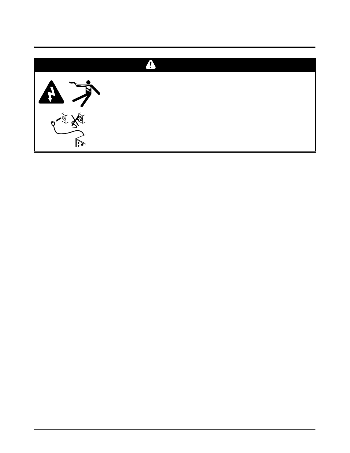
WARNING
ELECTRIC SHOCK CAN KILL
Disconnect electrical power before performing any maintenance.
All work requiring removal of the power supply cover must be performed
by a qualified technician.
See the safety information provided with your product for more safety
precautions.
Notice: Installation of the system at the installed site is subject to the approval of the Local
Inspection Authorities (LIA). Without approval of the LIA, modification of the factory installed
wiring voids the safety test marks (for example, cCSAus, CCC, CE, GOST-TR, UkrSEPRO,
RCM, EAC) applied to the product in the Hypertherm factory, and the safety certificates
provided by Hypertherm become invalid after modification.
Tools and materials needed
Wire strippers
Wire terminal crimper
Assorted Phillips
Electric drill with a 15 mm or 19/32 inch drill bit
0.75 mm
OLFLEX
M3 (#5) insulated ring terminals, quantity 2
2
or 18 AWG, 2 wire, non-shielded cable similar to
®
190 (manufacturer’s part number 601802)
428689 Kit contents
Part number Description Quantity
®
and TORX® screwdrivers
008279 Strain relief 1
075529 M3 x 10 mm machine screw with lock washer 2
Powermax45 XP Field Service Bulletin 809520 3
Raw Arc Voltage Kit
1
234
3
2
4
1
3
1
2
Install the interface cable
Connecting a cable to the power board to bypass the voltage divider board and access raw arc
voltage must be done by trained service personnel.
SHOCK HAZARD, ENERGY HAZARD, AND FIRE HAZARD
Connecting directly to the plasma circuit for access to raw arc voltage
increases the risk of shock hazard, energy hazard, and fire hazard in the
event of a single fault. The output voltage and the output current of the
circuit are specified on the data plate.
Remove cover and component barrier
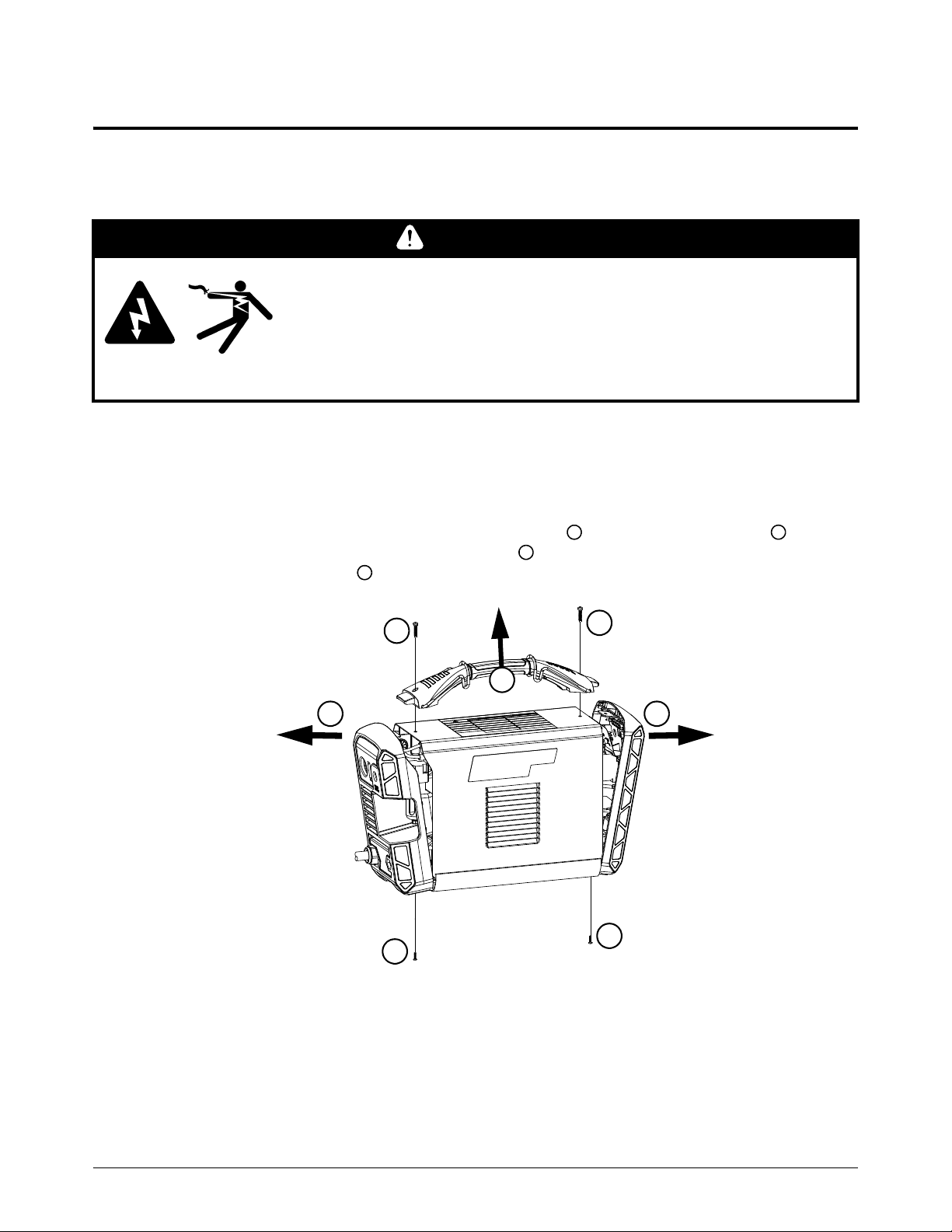
1. Turn OFF the power. Disconnect the power cord and gas supply.
WARNING
2. Remove the two screws from the power supply handle . Remove the two screws from the
bottom of the front and rear panels. Tilt the tops of the front and rear panels away from the
unit to pull the handle out .
4 809520 Field Service Bulletin Powermax45 XP
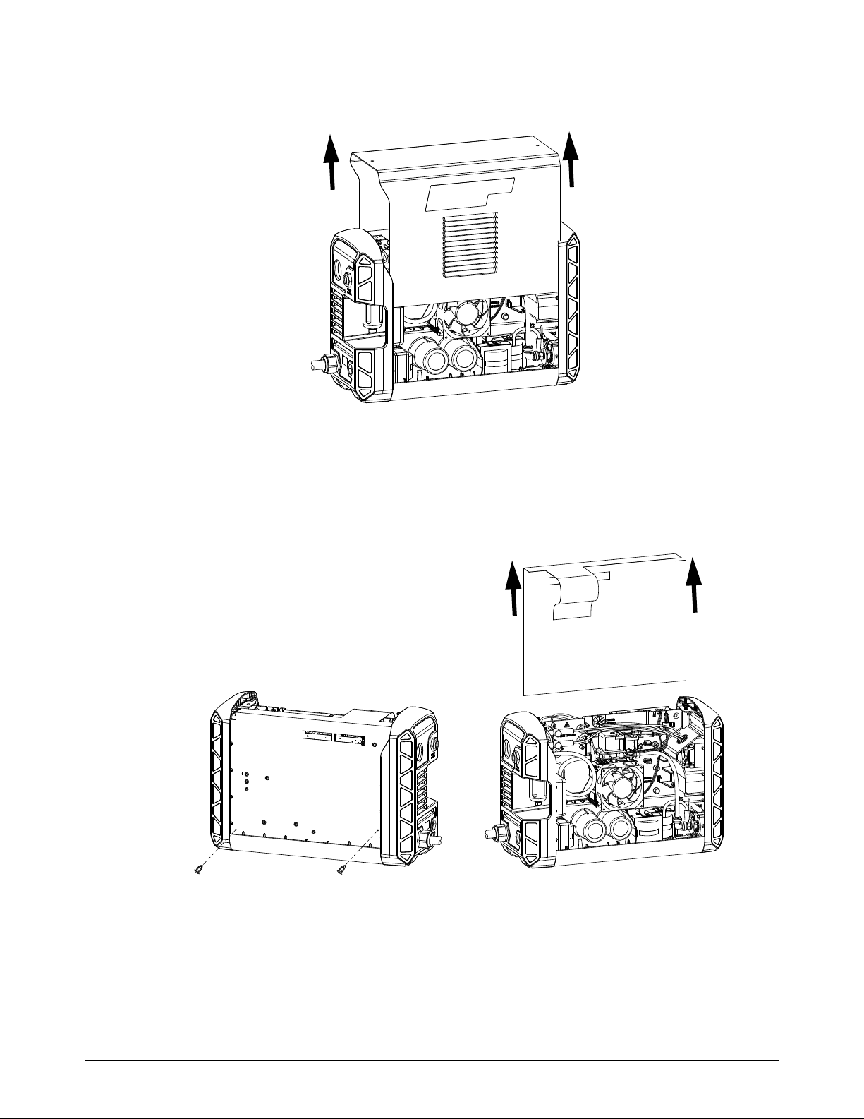
3. Slide the cover off.
Raw Arc Voltage Kit
4. Remove the two plastic pins that secure the component barrier to the main power board. Slide
the component barrier off.
Powermax45 XP Field Service Bulletin 809520 5
Raw Arc Voltage Kit
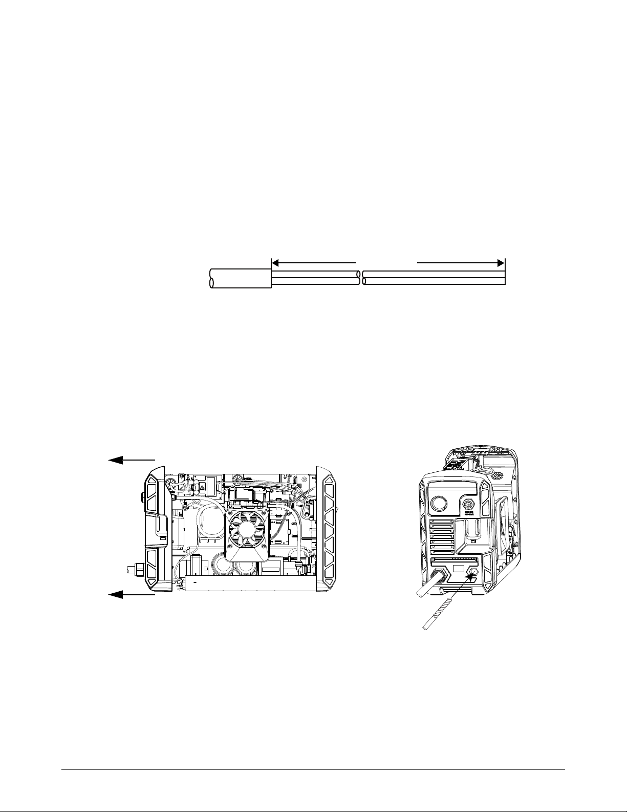
48.3 cm (19 inches)
Prepare the interface cable
1. Use 2 conductor, non-shielded 18 AWG wires to connect to the power supply. Measure the
distance needed to connect from the CNC to the power supply. Add an additional 51.5 cm
(20.25 inches) to make the connection inside the power supply.
2. Cut back the outer jacket 48.3 cm (19 inches) from one end of the cable. Make sure you do not
cut into the insulation on the two 18 AWG wires.
Do not strip the wire ends until after they have been routed through the
power supply.
Install the strain relief
1. Pull the rear panel slightly away from the unit leaving enough space to drill a hole while avoiding
any contact with internal components or wires when drilling.
2. Use a 15 mm (19/32 inch) drill to drill out the interface cable entry point on the panel. Clean the
area of any chips from drilling.
6 809520 Field Service Bulletin Powermax45 XP
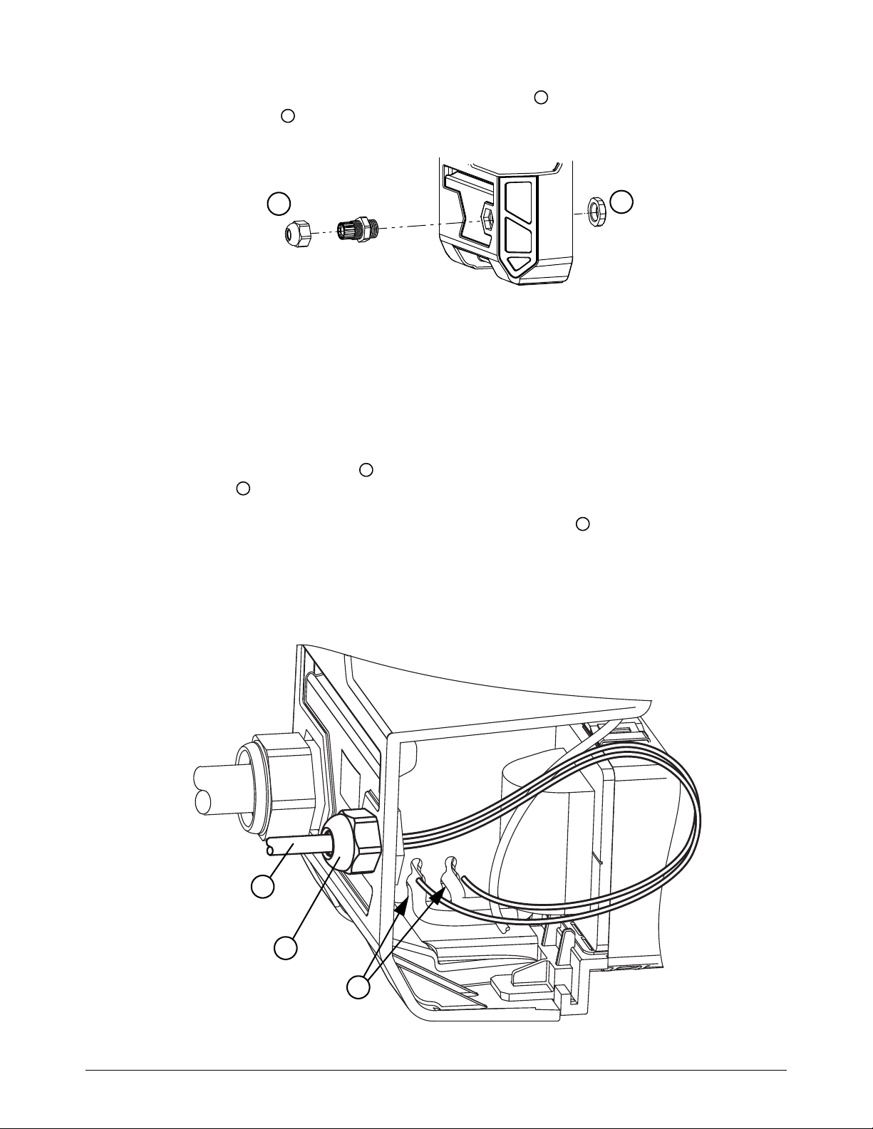
3. Attach the strain relief (008279) and tighten the inner nut to secure it to the panel. Attach the
1
2
1
2
1
2
3
3
1
2
outer retention nut but do not tighten.
Connect the interface cable
1. Pass the cable through the strain relief. The outer jacket should slightly protrude through the
back of the strain relief. Make sure the wire length is 48.3 cm (19 inches) inside the power
supply.
Raw Arc Voltage Kit
2. Tighten the outer retention nut on the strain relief. Make sure the strain relief closes on the
outer jacket of the cable and holds it securely in place.
3. Insert the interface cable wires through the pass-through holes used by the transformer to
reach the other side of the unit.
Different power supply configurations will have the transformer wires
routed differently. Use the pass-through holes that are not utilized by the
transformer.
Powermax45 XP Field Service Bulletin 809520 7

Raw Arc Voltage Kit
( + )
( - )
(-)
(+)
( + )
( - )
( + )
( - )
( + )
( - )
4. Route the wires to bring the ends to the (-) and (+) threaded inserts on the main circuit board.
5. Strip the insulation 1.27 mm (0.5 inches) from the ends of the wires.
6. Crimp an M3 insulated terminal ring connector on the end of each wire. Make sure there are no
loose wire strands.
7. Connect the positive lead to the (+) threaded insert (J22) on the power supply board. Use one
of the screws included in the kit (075529). Tighten the screw to 23.0 kg∙cm (20 inch·pounds).
Make sure the wire runs downward and the insulated part of the ring terminal is off the board.
8. Connect the negative lead to the (-) threaded insert (J9) on the power supply board. Use one of
the screws included in the kit (075529). Tighten the screw to 23.0 kg∙cm (20 inch-pounds).
Make sure the wire runs downward and the insulated part of the ring terminal is off the board.
9. Make sure to mark on the other end of the cable which wire is positive (+) and which is
negative (-).
10. Replace the component barrier and secure it to the main circuit board with the two plastic pins.
11 . Set the front and rear panels back in place.
8 809520 Field Service Bulletin Powermax45 XP

Raw Arc Voltage Kit
12. Make sure the ground clip is connected to the ground wire. The clip should be set in place to
accept the screw from the handle.
13. Slide the cover back on.
14. Tilt the front and rear panels to reattach the handle.
15. Secure the front and rear panel bottom screws.
16. Secure the front and rear panel top screws.
17. Connect the other end of the cable to the equipment according to the manufacturer’s
instructions. Remember to observe polarity.
Notice: The output of the internal voltage divider board is designed to prevent shock, energy
and fire hazards, and is intended to satisfy most codes and standards for external wiring outside
the electrical enclosure. All external wiring practices for an unprotected raw arc voltage
should be reviewed and approved by the Local Inspection Authorities (LIA) at the
time of installation prior to operation and use.
Raw arc voltage wiring terminals and connections should not be exposed to accidental
contact under normal and single fault conditions.
External wiring from an unprotected (that is, no voltage divider used in the power source)
raw arc voltage routed inside conduit between electrical enclosures will normally satisfy all
electrical codes and standards worldwide. Failure to address the hazards associated
with live contact, accessibility and single fault failures to this unprotected output
can result in death or fire.
Powermax45 XP Field Service Bulletin 809520 9

Raw Arc Voltage Kit
A voltage divider board inside the CNC protects only the CNC and does NOT protect the
external interconnecting wiring between the power source and the CNC. Over-current
protection may be required to protect the user and/or machine in fault conditions.
External wiring outside the electrical enclosure should be suitable for the installation and meet
national and local regulations (for example, NFPA 70 NEC, NFPA 79, Canadian Electrical Code,
CSA/CAN E60974-1, IEC 60204-1, BS 7671) or other codes and/or standards applicable to
the installed site where the equipment will be operated.
10 809520 Field Service Bulletin Powermax45 XP

Introduction
Objet
Kit de tension d’arc brute
AVERTISSEMENT
UN CHOC ÉLECTRIQUE PEUT ÊTRE MORTEL
Avant tout entretien, débrancher l’alimentation électrique.
Tous les travaux nécessitant le retrait du couvercle de la source
de courant doivent être effectués par un technicien qualifié.
Se reporter aux consignes de sécurité incluses avec votre produit pour
d’autres mesures de sécurité.
Le présent bulletin de service sur le terrain décrit comment installer un câble d’interface de machine
fourni par le client n’utilisant pas le diviseur de tension interne 50:1 sur le Powermax45 XP.
Avis : l’installation du système sur le site doit être approuvée par le service d’inspection local (LIA). Sans
l’approbation de la LIA, la modification du câblage fait en usine annule les sigles des essais de sécurité
(comme par exemple cCSAus, CCC, CE, GOST-TR, UkrSEPRO, RCM, EAC) apposés au produit
à l’usine Hypertherm. Les certificats de sécurité fournis par Hypertherm seront également déclarés nuls
et non avenus après ladite modification.
Outils et matériel requis
Pince à dénuder
Pinces à sertir
Tournevis Phillips
Perceuse électrique avec mèche de 15 mm (19/32 po)
0,75 mm
2
(18 AWG), câble non blindé, à 2 fils, similaire au OLFLEX®190
(numéro de référence du fabricant 601802)
Deux cosses rondes isolées M3 (nº 5)
Contenu du kit 428689
®
et TORX® assortis
Numéro de référence Description Quantité
008279 Serre-câble 1
075529 Vis mécanique M3 x 10 mm avec rondelle de blocage 2
Powermax45 XP Bulletin de service sur le terrain 809520 11

Kit de tension d’arc brute
1
2
3
4
3
2
4
1
3
1
2
Installer le câble d’interface
Le branchement d’un câble au panneau d’alimentation afin de contourner le panneau diviseur
de tension et accéder à la tension d’arc brute doit être effectué par un technicien de maintenance
qualifié.
AVERTISSEMENT
DANGER D’ÉLECTROCUTION, D’ÉNERGIE ET D’INCENDIE
Le raccordement direct au circuit plasma pour accéder à la tension
de l’arc brute augmente le danger d’électrocution, de problèmes
d’énergie et d’incendie s’il y a le moindre défaut. La tension de sortie et
le courant de sortie du circuit sont indiqués sur la plaque signalétique.
Retirer le couvercle et la barrière du composant
1. Couper l’alimentation électrique (OFF). Couper l’alimentation en électricité et en gaz.
2. Retirer les deux vis de la poignée de la source de courant . Retirer les deux vis de la partie
inférieure des panneaux avant et arrière. Écarter la partie supérieure des panneaux avant
et arrière de l’unité principale pour retirer la poignée .
12 809520 Bulletin de service sur le terrain Powermax45 XP

3. Retirer le couvercle en le faisant glisser.
Kit de tension d’arc brute
4. Retirer les deux épingles de plastique qui fixent la barrière du composant au circuit imprimé
d’alimentation principal. Retirer la barrière de composant en le faisant glisser.
Powermax45 XP Bulletin de service sur le terrain 809520 13

Kit de tension d’arc brute
48,3 cm (19 po)
Préparation du câble d’interface
1. Utiliser des fils non-blindés 18 AWG à 2 conducteurs pour effectuer le branchement
à la source de courant. Mesurer la distance requise pour effectuer la connexion entre
la commande numérique par ordinateur (CNC) et l’alimentation électrique.
Ajouter 51,5 cm (20.25 po) pour la connexion à l’intérieur de la source de courant.
2. À une extrémité du câble, retirer la gaine extérieure du fil sur une longueur
de 48,3 cm (19 po). S’assurer de ne pas endommager l’isolation des deux câbles 18 AWG.
Il est important de ne pas dégainer les extrémités des fils avant qu’ils
ne soient correctement insérés dans la source de courant.
Installation du protecteur de câble
1. Écarter légèrement le panneau arrière de l’unité afin de dégager suffisamment d’espace pour
pouvoir percer en évitant tout contact avec les composants internes ou les fils.
2. Utiliser une mèche de 15 mm (19/32 po) pour percer le trou d’accès du câble d’interface
dans le panneau arrière. Nettoyer tout débris de perçage.
14 809520 Bulletin de service sur le terrain Powermax45 XP

3. Attacher le protecteur de câble (008279) et serrer l’écrou interne pour le fixer au panneau.
1
2
1
2
1
2
3
3
1
2
Attacher l’écrou de rétention externe mais sans le serrer.
Connexion du câble d’interface
1. Insérer le câble dans le protecteur de câble. La gaine extérieure doit ressortir un peu de l’arrière
du protecteur de câble. S’assurer qu’il y a bien 48,3 cm (19 po) de fil à l’intérieur de la source
de courant.
Kit de tension d’arc brute
2. Serrer l’écrou de rétention externe au protecteur de câble. S’assurer que le protecteur
de câble ferme bien au niveau de la gaine extérieure du câble et le tienne bien en place.
3. Insérer les fils du câble d’interface dans les passe-câbles utilisés par le transformateur pour
atteindre l’autre côté de l’unité.
Les fils du transformateur emprunteront des chemins différents selon
la configuration de la source de courant. Utiliser les passe-câbles qui
ne sont pas déjà occupés par le transformateur.
Powermax45 XP Bulletin de service sur le terrain 809520 15

Kit de tension d’arc brute
( + )
( - )
(-)
(+)
( + )
( - )
( + )
( - )
( + )
( - )
4. Amener les extrémités des fils aux embouts filetés (-) et (+) du circuit imprimé.
5. Dégainer 1,27 cm (1/2 po) des extrémités des fils.
6. Sertir l’extrémité de chaque fil d’une cosse ronde terminale isolée M3. S’assurer qu’aucun
fil n’est pas connecté.
7. Brancher le brin positif à l’embout fileté (+) du circuit imprimé d’alimentation électrique (J22).
Utiliser une des vis comprises dans le kit (075529). Serrer la vis à 23 kg∙cm (20 po-lb).
S’assurer que le fil descende et que la partie isolée de la cosse ronde ne touche pas au circuit
imprimé.
8. Brancher le fil négatif à l’embout fileté (-) du circuit imprimé d’alimentation électrique (J9).
Utiliser une des vis comprises dans le kit (075529). Serrer la vis à 23 kg∙cm (20 po-lb).
S’assurer que le fil descende et que la partie isolée de la cosse ronde ne touche pas au circuit
imprimé.
9. S’assurer de marquer à l’autre extrémité du câble quel fil est positif (+) et lequel est négatif (-).
10. Replacer la barrière du composant et la fixer au circuit imprimé d’alimentation principale avec
les deux épingles en plastique.
11 . Replacer les panneaux avant et arrière.
16 809520 Bulletin de service sur le terrain Powermax45 XP

Kit de tension d’arc brute
12. S’assurer que le collier de mise à la terre est connecté au fil de mise à la terre. Le collier doit
être en place pour pouvoir insérer les vis de la poignée.
13. Glisser le couvercle en place.
14. Incliner les panneaux avant et arrière pour rattacher la poignée.
15. Fixer les vis au bas des panneaux avant et arrière.
16. Fixer les vis en haut des panneaux avant et arrière.
17. Brancher l’autre extrémité du câble à l’équipement selon les instructions du fabricant.
Ne pas oublier de respecter la polarité.
Avis : La sortie du panneau diviseur de tension interne est conçue de sorte à éviter tout risque
de choc électrique, de problème d’énergie et d’incendie et elle est conforme à la plupart des
codes et normes relatives au câblage externe hors du coffret électrique. Tout câblage externe
d’une tension d’arc brute non-protégée doit être revu et approuvé par le service
d’inspection local (LIA) au moment de l’installation et avant toute utilisation.
Les bornes de câblage et les connexions de la tension d’arc brute ne doivent pas être
exposées à un contact accidentel sous des conditions normales ou de défaut unique.
Le câblage externe d’une tension d’arc brute non protégée (aucun diviseur de tension dans
la source de courant) passé à l’intérieur de tuyaux entre les coffrets électriques respectera
généralement tous les codes et normes électriques internationaux. L’incapacité à mettre
en place des mesures préventives concernant le contact direct, l’accessibilité
et les défaillances à défaut unique de ce panneau non-protégé peut entraîner
la mort ou causer un incendie.
Powermax45 XP Bulletin de service sur le terrain 809520 17

Kit de tension d’arc brute
Un diviseur de tension à l’intérieur de la commande numérique par ordinateur (CNC) ne protège
que cette dernière et NE PROTÈGE PAS le câblage connectant l’alimentation électrique
et le CNC. Une protection de surintensité peut être nécessaire afin de protéger l’utilisateur
et/ou la machine en cas de défaillance.
Le câblage externe hors du coffret électrique doit être adapté à l’installation et être conforme
aux codes locaux et nationaux (par exemple NFPA 70 NEC, NFPA 79, le Code canadien
de l’électricité, CSA/CAN E60974-1, IEC 60204-1 et BS 7671) ou autres codes ou normes
s’appliquant au site d’installation où l'équipement est exploité.
18 809520 Bulletin de service sur le terrain Powermax45 XP
 Loading...