

Page 1

Plasma Arc
Cutting System
Service Manual
802920 Revision 1
®
EN50199
EN50192
Page 2

®
Plasma Arc Cutting System
Service Manual
IM-292
(P/N 802920)
Revision 1 July, 1998
Hypertherm, Inc.
P.O. Box 5010
Hanover, New Hampshire 03755-5010
Tel.: 603 643-3441
Fax: 603 643-5352
http://www.hypertherm.com
© Copyright 1998 Hypertherm, Inc.
All Rights Reserved
Hypertherm, HyDefinition, Powermax and LongLife are trademarks of Hypertherm, Inc.
and may be registered in the United States and/or other countries
Page 3

Hypertherm, Inc.
Etna Road, P.O. Box 5010
Hanover, NH 03755 USA
603-643-3441 Tel (Main Office)
603-643-5352 Fax (All Departments)
800-643-9 878 Tel (Technical Ser vice)
800-737-2978 Tel (Customer Service)
Hypertherm Automation
5 Technology Drive, Suite 300
West Lebanon, NH 03784 USA
603-298-7970 Tel
603-298-7977 Fax
Hypertherm Plasmatechnik GmbH
Technologiepark Hanau
Rodenbacher Chaussee 6
D-63457 Hanau-Wolfgang, Germany
49 6181 58 2100 Tel
49 6181 58 213 4 Fax
49 6181 58 212 3 (Technical Service)
Hypertherm Singapore Pte Ltd
No. 19 Kaki Bukit Road 2
K.B. Warehouse Complex
Singapore 417847, Republic of Singapore
65 841 2489 Tel
65 841 2490 Fax
65 841 24 89 (Technical Service)
Japan
Shinjuku Park Tower, 30th Floor
3-7-1 Nishi-Shinjuku, Shinjuku-ku, Tokyo,
163-1030, Japan
81 03 5326 3142 Tel
81 03 5326 3001 Fax
Hypertherm UK Ltd
9 Berkeley Court, Manor Park
Runcorn, Cheshire, England WA7 1TQ
44 1928 579 074 Tel
44 1928 579 604 Fax
France
15 Impasse des Rosiers
95610 Eragny, France
33 1 30 37 15 28 Tel
33 1 30 37 15 79 Fax
Hypertherm S.r.L.
Via Torino 2
20123 Milan, Italy
39 02 725 46 312 Tel
39 02 725 46 400 Fax
39 02 725 46 3 14 Tel (Technical Service)
Hypertherm B.V.
Burg. Haverkampstraat 13
7091 CN Dinxperlo, The Netherlands
31 315 655866 Tel
31 315 655886 Fax
Hypertherm B.V.
European Technical Service Organization (ETSO)
Edisontraat 12
3281 NC Numansdorp, The Netherlands
00 800 49 73 7843 Toll Free in Europe
31 186 659494 Tel
31 186 659495 Fax
Page 4

ELECTROMAGNETIC COMPATIBILITY (EMC)
EMC INTRODUCTION
Hypertherm's CE-marked equipment is built
in compliance with standard EN50199. The
equipment should be installed and used in
accordance with the information below to
achieve electromagnetic compatibility.
The limits required by EN50199 may not be
adequate to completely eliminate interference when the affected equipment is in
close proximity or has a high degree of sensitivity. In such cases it may be necessary to
use other measures to further reduce interference.
This plasma equipment is designed for use
only in an industrial environment.
INSTALLATION AND USE
The user is responsible for installing and
using the plasma equipment according to
the manufacturer's instructions. If electromagnetic disturbances are detected then it
shall be the responsibility of the user to resolve the situation with the technical assistance of the manufacturer. In some cases
this remedial action may be as simple as
earthing the cutting circuit, see Earthing of
Workpiece. In other cases it could involve
constructing an electromagnetic screen enclosing the power source and the work complete with associated input filters. In all
cases electromagnetic disturbances must
be reduced to the point where they are no
longer troublesome.
ASSESSMENT OF AREA
Before installing the equipment the user
shall make an assessment of potential electromagnetic problems in the surrounding
area. The following shall be taken into
account:
a. Other supply cables, control cables, signalling and telephone cables; above, below
and adjacent to the cutting equipment.
b. Radio and television transmitters and
receivers.
c. Computer and other control equipment.
d. Safety critical equipment, for example
guarding of industrial equipment.
e. Health of the people around, for
example the use of pacemakers and hearing aids.
f. Equipment used for calibration or measurement.
g. Immunity of other equipment in the environment. User shall ensure that other
equipment being used in the environment is
compatible. This may require additional protection measures.
h. Time of day that cutting or other activities
are to be carried out.
Earthing of Workpiece
Where the workpiece is not bonded to earth
for electrical safety, nor connected to earth
because of its size and position, for example,
ship's hull or building steelwork, a connection
bonding the workpiece to earth may reduce
emissions in some, but not all instances.
Care should be taken to prevent the earthing
of the workpiece increasing the risk of injury
to users, or damage to other electrical equipment. Where necessary, the connection of
the workpiece to earth should be made by a
direct connection to the workpiece, but in
some countries where direct connection is
not permitted, the bonding should be
achieved by suitable capacitances selected
according to national regulations.
Note. The cutting circuit may or may not be
earthed for safety reasons. Changing the
earthing arrangements should only be authorized by a person who is competent to
assess whether the changes will increase
the risk of injury, for example, by allowing
parallel cutting current return paths which
may damage the earth circuits of other
equipment. Further guidance is given in IEC
TC26 (sec)94 and IEC TC26/108A/CD Arc
Welding Equipment Installation and Use.
Screening and Shielding
Selective screening and shielding of other
cables and equipment in the surrounding
area may alleviate problems of interference.
Screening of the entire plasma cutting installation may be considered for special applications
The size of the surrounding area to be considered will depend on the structure of the
building and other activities that are taking
place. The surrounding area may extend
beyond the boundaries of the premises.
METHODS OF REDUCING EMISSIONS
Mains Supply
Cutting equipment must be connected to the
mains supply according to the manufacturer's recommendations. If interference occurs, it may be necessary to take additional
precautions such as filtering of the mains
supply. Consideration should be given to
shielding the supply cable of permanently
installed cutting equipment, in metallic conduit or equivalent. Shielding should be electrically continuous throughout its length.
The shielding should be connected to the
cutting mains supply so that good electrical
contact is maintained between the conduit
and the cutting power source enclosure
Maintenance of Cutting Equipment
The cutting equipment must be routinely
maintained according to the manufacturer's
recommendations. All access and service
doors and covers should be closed and
properly fastened when the cutting equipment is in operation. The cutting equipment
should not be modified in any way except for
those changes and adjustments covered in
the manufacturer's instructions. In particular, the spark gaps of arc striking and stabilizing devices should be adjusted and maintained according to the manufacturer's
recommendations.
Cutting Cables
The cutting cables should be kept as short
as possible and should be positioned close
together, running at or close to the floor
level.
Equipotential Bonding
Bonding of all metallic components in the
cutting installation and adjacent to it should
be considered. However, metallic components bonded to the workpiece will increase
the risk that the operator could receive a
shock by touching these metallic components and the electrode at the same time.
The operator should be insulated from all
such bonded metallic components.
HYPERTHERM Plasma Systems i
Page 5

WARRANTY
ii HYPERTHERM Plasma Systems
5-00
WARNING
Genuine Hypertherm parts are the factory-recommended
replacement parts for your Hypertherm system. Any damage
caused by the use of other than genuine Hypertherm parts
may not be covered by the Hypertherm warranty.
WARNING
You are responsible for the safe use of the Product.
Hypertherm does not and cannot make any guarantee or
warranty regarding the safe use of the Product in your
environment.
GENERAL
Hypertherm, Inc. warrants that its Products shall be free from
defects in materials and workmanship, if Hypertherm is
notified of a defect (i) with respect to the power supply within
a period of two (2) years from the date of its delivery to you,
and (ii) with respect to the torch and leads within a period of
one (1) year from its date of delivery to you. This warranty
shall not apply to any Product which has been incorrectly
installed, modified, or otherwise damaged. Hypertherm, at
its sole option, shall repair, replace, or adjust, free of charge,
any defective Products covered by this warranty which shall
be returned with Hypertherm’s prior authorization (which
shall not be unreasonably withheld), properly packed, to
Hypertherm’s place of business in Hanover, New Hampshire,
or to an authorized Hypertherm repair facility, all costs,
insurance and freight prepaid. Hypertherm shall not be liable
for any repairs, replacement, or adjustments of Products
covered by this warranty, except those made pursuant to
this paragraph or with Hypertherm’s prior written consent.
The warranty above is exclusive and is in lieu of all other
warranties, express, implied, statutory, or otherwise with
respect to the Products or as to the results which may
be obtained therefrom, and all implied warranties or
conditions of quality or of merchantability or fitness
for a particular purpose or against infringement. The
foregoing shall constitute the sole and exclusive remedy
for any breach by Hypertherm of its warranty.
Distributors/OEMs may offer different or additional warranties,
but Distributors/OEMs are not authorized to give any
additional warranty protection to you or make any representation to you purporting to be binding upon Hypertherm.
PATENT INDEMNITY
Except only in cases of products not manufactured by
Hypertherm or manufactured by a person other than
Hypertherm not in strict conformity with Hypertherm’s
specifications and in cases of designs, processes, formulae,
or combinations not developed or purported to be developed
by Hypertherm, Hypertherm will defend or settle, at its own
expense, any suit or proceeding brought against you alleging
that the use of the Hypertherm product, alone and not in
combination with any other product not supplied by
Hypertherm, infringes any patent of any third party. You shall
notify Hypertherm promptly upon learning of any action or
threatened action in connection with any such alleged
infringement, and Hypertherm’s obligation to indemnify shall
be conditioned upon Hypertherm’s sole control of, and the
indemnified party’s cooperation and assistance in, the
defense of the claim.
LIMITATION OF LIABILITY
In no event shall Hypertherm be liable to any person or
entity for any incidental, consequential, indirect, or
punitive damages (including but not limited to lost
profits) regardless of whether such liability is based on
breach of contract, tort, strict liability, breach of
warranties, failure of essential purpose or otherwise and
even if advised of the possibility of such damages.
LIABILITY CAP
In no event shall Hypertherm’s liability, whether such
liability is based on breach of contract, tort, strict
liability, breach of warranties, failure of essential purpose
or otherwise, for any claim action suit or proceeding
arising out of or relating to the use of the Products
exceed in the aggregate the amount paid for the
Products that gave rise to such claim.
INSURANCE
At all times you will have and maintain insurance in such
quantities and types, and with coverage sufficient and
appropriate to defend and to hold Hypertherm harmless in
the event of any cause of action arising from the use of the
Products.
NATIONAL AND LOCAL CODES
National and Local codes governing plumbing and electrical
installation shall take precedent over any instructions
contained in this manual. In no event shall Hypertherm be
liable for injury to persons or property damage by reason of
any code violation or poor work practices.
TRANSFER OF RIGHTS
You may transfer any remaining rights you may have
hereunder only in connection with the sale of all or
substantially all of your assets or capital stock to a successor
in interest who agrees to be bound by all of the terms and
conditions of this Warranty.
Page 6

TABLE OF CONTENTS
ELECTROMAGNETIC COMPATIBILITY ...............................................................................................................i
WARRANTY ..........................................................................................................................................................ii
SECTION 1 SAFETY .................................................................................................................................. 1-1
About Notes, Cautions & Warnings.................................................................................................................... 1-1
Safety Instructions.............................................................................................................................................. 1-2
Eye Protection ............................................................................................................................................. 1-2
Skin Protection ............................................................................................................................................ 1-2
Toxic Fume Protection ................................................................................................................................. 1-2
Fire Prevention ............................................................................................................................................ 1-2
Electric Shock Prevention............................................................................................................................ 1-2
Explosion Prevention ................................................................................................................................... 1-3
Noise Protection .......................................................................................................................................... 1-4
Grounding ................................................................................................................................................. 1-4
Safety Reminders ........................................................................................................................................ 1-4
Electronic Health Support Equipment.......................................................................................................... 1-4
SECTION 1A SÉCURITÉ ........................................................................................................................... 1a-1
Au sujet des Notes, Attention et avertissement................................................................................................ 1a-1
Consignes de sécurité...................................................................................................................................... 1a-2
Protection des yeux ................................................................................................................................... 1a-2
Protection de la peau................................................................................................................................. 1a-2
Prévention des vapeurs toxiques .............................................................................................................. 1a-2
Prévention des incendies .......................................................................................................................... 1a-2
Prévention des chocs électriques .............................................................................................................. 1a-2
Prévention des explosions ......................................................................................................................... 1a-3
Protection contre le bruit............................................................................................................................ 1a-4
Mise à la masse et à la terre ..................................................................................................................... 1a-4
Rappels de sécurité ................................................................................................................................... 1a-4
Prothèses électroniques ............................................................................................................................ 1a-4
SECTION 2 SPECIFICATIONS ................................................................................................................... 2-1
Introduction ........................................................................................................................................................ 2-2
Specifications ..................................................................................................................................................... 2-2
Power Supply .............................................................................................................................................. 2-2
PAC110 Torch ............................................................................................................................................. 2-3
S Mark............................................................................................................................................................. 2-4
IEC Symbols Used ............................................................................................................................................. 2-4
SECTION 3 MAINTENANCE....................................................................................................................... 3-1
Routine Maintenance ......................................................................................................................................... 3-2
Theory of Operation .......................................................................................................................................... 3-3
General ........................................................................................................................................................ 3-3
Functional Description ................................................................................................................................. 3-3
Trouble LED Indicators ...................................................................................................................................... 3-8
Troubleshooting ................................................................................................................................................. 3-9
PAC110 Torch Repair ....................................................................................................................................... 3-20
Technical Questions ......................................................................................................................................... 3-22
Service Manual
iii
Page 7

TABLE OF CONTENTS
SECTION 4 PARTS LIST ............................................................................................................................. 4-1
115/230 Volt Power Supply ................................................................................................................................ 4-2
200 Volt Power Supply ....................................................................................................................................... 4-4
PAC110 Torch Assembly and Torch Leads ....................................................................................................... 4-6
Consumable Parts.............................................................................................................................................. 4-7
ILLUSTRATIONS
Figure 2-1 Powermax350 Plasma Cutting System .................................................................................... 2-3
Figure 2-2 PAC110 Torch with Dimensions ............................................................................................... 2-3
Figure 3-1 Repositioning Input Voltage Selector Switch (115/230 volt unit only) ...................................... 3-3
Figure 3-2.1 Functional Block Diagram, 115/230 Volt Unit ........................................................................... 3-4
Figure 3-2.2 Functional Block Diagram, 200 Volt Unit.................................................................................. 3-6
Figure 3-3 Trouble LED Indicators............................................................................................................. 3-8
Figure 3-4.1 Wiring Diagram, 115/230 Volt Unit ......................................................................................... 3-12
Figure 3-4.2 Wiring Diagram, 200 Volt Unit ................................................................................................ 3-14
Figure 3-5.1 Wiring Harness Diagram, 115/230 Volt Unit ........................................................................... 3-16
Figure 3-5.2 Wiring Harness Diagram, 200 Volt Unit.................................................................................. 3-18
Figure 3-6 PAC110 Torch Repair ............................................................................................................. 3-21
Figure 4-1.1 115/230 Volt Powermax350 Power Supply .............................................................................. 4-3
Figure 4-1.2 200 Volt Powermax350 Power Supply ..................................................................................... 4-5
Figure 4-2 PAC110 Assembly and Torch Leads ....................................................................................... 4-6
Figure 4-3 Consumable Parts.................................................................................................................... 4-7
iv
Service Manual
Page 8

PARTS LIST
blank
4-8
Service Manual
Page 9

HYPERTHERM Plasma Systems 1-1
Section 1
SAFETY
In this section:
Recognize Safety Information.........................................................................................................................1-2
Follow Safety Instructions ...............................................................................................................................1-2
Cutting Can Cause Fire or Explosion..............................................................................................................1-2
Electric Shock Can Kill....................................................................................................................................1-3
Cutting Can Produce Toxic Fumes..................................................................................................................1-3
A Plasma Arc Can Cause Injury and Burns.....................................................................................................1-4
Arc Rays Can Burn Eyes and Skin .................................................................................................................1-4
Grounding Safety ............................................................................................................................................1-4
Compressed Gas Equipment Safety...............................................................................................................1-5
Gas Cylinders Can Explode If Damaged ........................................................................................................1-5
Noise Can Damage Hearing ...........................................................................................................................1-5
Pacemaker and Hearing Aid Operation...........................................................................................................1-5
A Plasma Arc Can Damage Frozen Pipes ......................................................................................................1-5
Additional Safety Information ..........................................................................................................................1-5
Warning Label.................................................................................................................................................1-6
Page 10

SAFETY
1-2 HYPERTHERM Plasma Systems
11-98
SAFETY
RECOGNIZE SAFETY INFORMATION
The symbols shown in this section are used to
identify potential hazards. When you see a safety
symbol in this manual or on your machine, understand
the potential for personal injury, and follow the related
instructions to avoid the hazard.
FOLLOW SAFETY INSTRUCTIONS
Read carefully all safety messages in this manual and
safety labels on your machine.
• Keep the safety labels on your machine in good
condition. Replace missing or damaged labels
immediately.
• Learn how to operate the machine and how to use
the controls properly. Do not let anyone operate it
without instruction.
• Keep your machine in proper working condition.
Unauthorized modifications to the machine may
affect safety and machine service life.
DANGER WARNING CAUTION
A signal word DANGER or WARNING is used with a
safety symbol. DANGER identifies the most serious
hazards.
• DANGER and WARNING safety labels are located
on your machine near specific hazards.
• WARNING safety messages precede related
instructions in this manual that may result in injury
or death if not followed correctly.
• CAUTION safety messages precede related
instructions in this manual that may result in
damage to equipment if not followed correctly.
Fire Prevention
• Be sure the area is safe before doing any cutting.
Keep a fire extinguisher nearby.
• Remove all flammables within 35 feet (10 m) of the
cutting area.
• Quench hot metal or allow it to cool before handling
or before letting it touch combustible materials.
• Never cut containers with potentially flammable
materials inside – they must be emptied and
properly cleaned first.
• Ventilate potentially flammable atmospheres before
cutting.
• When cutting with oxygen as the plasma gas, an
exhaust ventilation system is required.
Explosion Prevention
• Do not use the plasma system if explosive dust or
vapors may be present.
• Do not cut pressurized cylinders, pipes, or any
closed container.
• Do not cut containers that have held combustible
materials.
CUTTING CAN CAUSE FIRE OR EXPLOSION
WARNING
Explosion Hazard
Argon-Hydrogen and Methane
Hydrogen and methane are flammable gases that
present an explosion hazard. Keep flames away from
cylinders and hoses that contain methane or hydrogen
mixtures. Keep flames and sparks away from the torch
when using methane or argon-hydrogen plasma.
WARNING
Hydrogen Detonation with Aluminum Cutting
• When cutting aluminum underwater, or with the
water touching the underside of the aluminum, free
hydrogen gas may collect under the workpiece and
detonate during plasma cutting operations.
• Install an aeration manifold on the floor of the water
table to eliminate the possibility of hydrogen
detonation. Refer to the Appendix section of this
manual for aeration manifold details.
Page 11

Touching live electrical parts can cause a fatal shock
or severe burn.
• Operating the plasma system completes an
electrical circuit between the torch and the
workpiece. The workpiece and anything touching
the workpiece are part of the electrical circuit.
• Never touch the torch body, workpiece or the water
in a water table when the plasma system is
operating.
Electric Shock Prevention
All Hypertherm plasma systems use high voltage
in the cutting process (200 to 400 VDC are
common). Take the following precautions when
operating this system:
• Wear insulated gloves and boots, and keep your
body and clothing dry.
• Do not stand, sit or lie on – or touch – any wet
surface when using the plasma system.
• Insulate yourself from work and ground using dry
insulating mats or covers big enough to prevent any
physical contact with the work or ground. If you must
work in or near a damp area, use extreme caution.
• Provide a disconnect switch close to the power
supply with properly sized fuses. This switch allows
the operator to turn off the power supply quickly in
an emergency situation.
• When using a water table, be sure that it is correctly
connected to earth ground.
ELECTRIC SHOCK CAN KILL
• Install and ground this equipment according to the
instruction manual and in accordance with national
and local codes.
• Inspect the input power cord frequently for damage
or cracking of the cover. Replace a damaged power
cord immediately. Bare wiring can kill.
• Inspect and replace any worn or damaged torch
leads.
• Do not pick up the workpiece, including the waste
cutoff, while you cut. Leave the workpiece in place
or on the workbench with the work cable attached
during the cutting process.
• Before checking, cleaning or changing torch parts,
disconnect the main power or unplug the power
supply.
• Never bypass or shortcut the safety interlocks.
• Before removing any power supply or system
enclosure cover, disconnect electrical input power.
Wait 5 minutes after disconnecting the main power
to allow capacitors to discharge.
• Never operate the plasma system unless the power
supply covers are in place. Exposed power supply
connections present a severe electrical hazard.
• When making input connections, attach proper
grounding conductor first.
• Each Hypertherm plasma system is designed to be
used only with specific Hypertherm torches. Do not
substitute other torches which could overheat and
present a safety hazard.
Cutting can produce toxic fumes and gases that
deplete oxygen and cause injury or death.
• Keep the cutting area well ventilated or use an
approved air-supplied respirator.
• Do not cut in locations near degreasing, cleaning or
spraying operations. The vapors from certain
chlorinated solvents decompose to form phosgene
gas when exposed to ultraviolet radiation.
• Do not cut metal coated or containing toxic materials, such as zinc (galvanized), lead, cadmium or
CUTTING CAN PRODUCE TOXIC FUMES
beryllium, unless the area is well ventilated and the
operator wears an air-supplied respirator. The
coatings and any metals containing these elements
can produce toxic fumes when cut.
• Never cut containers with potentially toxic materials
inside – they must be emptied and properly cleaned
first.
• This product, when used for welding or cutting,
produces fumes or gases which contain chemicals
known to the State of California to cause birth
defects and, in some cases, cancer.
HYPERTHERM Plasma Systems 1-3
8-99
SAFETY
Page 12

SAFETY
1-4 HYPERTHERM Plasma Systems
4-99
SAFETY
Instant-On Torches
Plasma arc comes on immediately when the torch
switch is activated.
A PLASMA ARC CAN CAUSE INJURY AND BURNS
The plasma arc will cut quickly through gloves and
skin.
• Keep away from the torch tip.
• Do not hold metal near the cutting path.
• Never point the torch toward yourself or others.
Eye Protection Plasma arc rays produce intense
visible and invisible (ultraviolet and infrared) rays that
can burn eyes and skin.
• Use eye protection in accordance with applicable
national or local codes.
• Wear eye protection (safety glasses or goggles with
side shields, or a welding helmet) with appropriate
lens shading to protect your eyes from the arc’s
ultraviolet and infrared rays.
Lens Shade
Arc Current AWS (USA) ISO 4850
Up to 100 A No. 8 No. 11
100-200 A No. 10 No. 11-12
200-400 A No. 12 No. 13
Over 400 A No. 14 No. 14
ARC RAYS CAN BURN EYES AND SKIN
Skin Protection Wear protective clothing to protect
against burns caused by ultraviolet light, sparks and
hot metal.
• Gauntlet gloves, safety shoes and hat.
• Flame-retardant clothing to cover all exposed areas.
• Cuffless trousers to prevent entry of sparks and
slag.
• Remove any combustibles, such as a butane lighter
or matches, from your pockets before cutting.
Cutting Area Prepare the cutting area to reduce
reflection and transmission of ultraviolet light:
• Paint walls and other surfaces with dark colors to
reduce reflection.
• Use protective screens or barriers to protect others
from flash and glare.
• Warn others not to watch the arc. Use placards or
signs.
Work Cable Attach the work cable securely to the
workpiece or the work table with good metal-to-metal
contact. Do not connect it to the piece that will fall
away when the cut is complete.
Work Table Connect the work table to an earth
ground, in accordance with appropriate national or
local electrical codes.
GROUNDING SAFETY
Input Power
• Be sure to connect the power cord ground wire to
the ground in the disconnect box.
• If installation of the plasma system involves
connecting the power cord to the power supply, be
sure to connect the power cord ground wire
properly.
• Place the power cord's ground wire on the stud first,
then place any other ground wires on top of the
power cord ground. Fasten the retaining nut tightly.
• Tighten all electrical connections to avoid excessive
heating.
Page 13

SAFETY
HYPERTHERM Plasma Systems 1-5
11-98
SAFETY
• Never lubricate cylinder valves or regulators with oil
or grease.
• Use only correct gas cylinders, regulators, hoses
and fittings designed for the specific application.
• Maintain all compressed gas equipment and
associated parts in good condition.
• Label and color-code all gas hoses to identify the
type of gas in each hose. Consult applicable
national or local codes.
GAS CYLINDERS CAN
EXPLODE IF DAMAGED
COMPRESSED GAS EQUIPMENT SAFETY
Gas cylinders contain gas under high pressure. If
damaged, a cylinder can explode.
• Handle and use compressed gas cylinders in
accordance with applicable national or local codes.
• Never use a cylinder that is not upright and secured
in place.
• Keep the protective cap in place over valve except
when the cylinder is in use or connected for use.
• Never allow electrical contact between the plasma
arc and a cylinder.
• Never expose cylinders to excessive heat, sparks,
slag or open flame.
• Never use a hammer, wrench or other tool to open
a stuck cylinder valve.
Prolonged exposure to noise from cutting or gouging
can damage hearing.
• Use approved ear protection when using plasma
system.
• Warn others nearby about the noise hazard.
NOISE CAN DAMAGE HEARING
Pacemaker and hearing aid operation can be affected
by magnetic fields from high currents.
Pacemaker and hearing aid wearers should consult a
doctor before going near any plasma arc cutting and
gouging operations.
To reduce magnetic field hazards:
• Keep both the work cable and the torch lead to one
side, away from your body.
• Route the torch leads as close as possible to the
work cable.
• Do not wrap or drape the torch lead or work cable
around your body.
• Keep as far away from the power supply as
possible.
PACEMAKER AND HEARING
AID OPERATION
ADDITIONAL SAFETY INFORMATION
1. ANSI Standard Z49.1, Safety in Welding and Cutting, American
Welding Society, 550 LeJeune Road
P.O. Box 351020, Miami, FL 33135
2. ANSI Standard Z49.2, Fire Prevention in the Use of Cutting and
Welding Processes, American National Standards Institute
1430 Broadway, New York, NY 10018
3. ANSI Standard Z87.1, Safe Practices for Occupation and
Educational Eye and Face Protection, American National
Standards Institute, 1430 Broadway, New York, NY 10018
4. AWS F4.1, Recommended Safe Practices for the Preparation for
Welding and Cutting of Containers and Piping That Have Held
Hazardous Substances, American Welding Society
550 LeJeune Road, P.O. Box 351040, Miami, FL 33135
5. AWS F5.2, Recommended Safe Practices for Plasma Arc
Cutting, American Welding Society
550 LeJeune Road, P.O. Box 351040, Miami, FL 33135
6. CGA Pamphlet P-1, Safe Handling of Compressed Gases in
Cylinders, Compressed Gas Association
1235 Jefferson Davis Highway, Arlington, VA 22202
7. CSA Standard W117.2, Code for Safety in Welding and Cutting,
Canadian Standards Association Standard Sales
178 Rexdale Boulevard, Rexdale, Ontario M9W 1R3, Canada
8. NFPA Standard 51B, Cutting and Welding Processes, National
Fire Protection Association
470 Atlantic Avenue, Boston, MA 02210
9. NFPA Standard 70–1978, National Electrical Code, National Fire
Protection Association, 470 Atlantic Avenue, Boston, MA 02210
10. OSHA, Safety and Health Standards, 29FR 1910
U.S. Government Printing Office, Washington, D.C. 20402
A PLASMA ARC CAN
DAMAGE FROZEN PIPES
Frozen pipes may be damaged or can burst if you
attempt to thaw them with a plasma torch.
Page 14

SAFETY
1-6 HYPERTHERM Plasma Systems
8-99
SAFETY
WARNING LABEL
This warning label is affixed to some power supplies. It is
important that the operator and maintenance technician
understand the intent of these warning symbols as described.
The numbered text corresponds to the numbered boxes on
the label.
1. Cutting sparks can cause explosion or fire.
1.1 Keep flammables away from cutting.
1.2 Keep a fire extinguisher nearby, and have
a watchperson ready to use it.
1.3 Do not cut on any closed containers.
2. The plasma arc can cause injury and
burns.
2.1 Turn off power before disassembling torch.
2.2 Do not hold the material near cutting path.
2.3 Wear complete body protection.
3. Electric shock from torch or wiring can kill.
Protect yourself from electric shock.
3.1 Wear insulating gloves. Do not wear wet or
damaged gloves.
3.2 Insulate yourself from work and ground.
3.3 Disconnect input plug or power before
working on machine.
4. Breathing cutting fumes can be hazardous
to your health.
4.1 Keep your head out of the fumes.
4.2 Use forced ventilation or local exhaust to
remove the fumes.
4.3 Use ventilating fan to remove the fumes.
5. Arc rays can burn eyes and injure skin.
5.1 Wear hat and safety glasses. Use ear
protection and button shirt collar. Use
welding helmet with correct shade of filter.
Wear complete body protection.
6. Become trained and read the instructions
before working on the machine or cutting.
7. Do not remove or paint over (cover)
warning labels.
Page 15

S
ÉCURITÉ
Section 1a
SÉCURITÉ
Cette section comprend:
IDENTIFIER LES CONSIGNES DE SÉCURITÉ..............................................1a-2
SUIVRE LES INSTRUCTIONS DE SÉCURITÉ ...............................................1a-2
LE COUPAGE PEUT PROVOQUER UN INCENDIE OU UNE EXPLOSION ..1a-2
LES CHOCS ÉLECTRIQUES PEUVENT ÊTRE FATALS................................1a-3
LE COUPAGE PEUT PRODUIRE DES VAPEURS TOXIQUES......................1a-3
L’ARC PLASMA PEUT PROVOQUER DES BLESSURES
OU DES BRÛLURES .......................................................................................1a-4
LES RAYONS DE L’ARC PEUVENT BRÛLER LES YEUX ET LA PEAU ........1a-4
MISE À LA MASSE ET À LA TERRE ...............................................................1a-4
SÉCURITÉ DES BOUTEILLES DE GAZ COMPRIMÉ ....................................1a-5
LES BOUTEILLES DE GAZ COMPRIMÉ PEUVENT EXPLOSER EN CAS DE
DOMMAGES ...............................................................................................1a-5
LE BRUIT PEUT PROVOQUER DES PROBLÈMES AUDITIFS .....................1a-5
PACEMAKERS ET PROTHÈSES AUDITIVES ................................................1a-5
ÉTIQUETTE DE SÉCURITÉ ............................................................................1a-6
HYPERTHERM Systèmes plasma 1a-1
08/99
Page 16

S
ÉCURITÉ
IDENTIFIER LES CONSIGNES
DE SÉCURITÉ
Les symboles indiqués dans cette section sont utilisés pour
identifier les risques éventuels. Si vous trouvez un symbole
de sécurité, que ce soit dans ce manuel ou sur
l’équipement, soyez conscient des risques de blessures et
suivez les instructions correspondantes afin d’éviter ces
risques.
SUIVRE LES INSTRUCTIONS
DE SÉCURITÉ
Lire attentivement toutes les consignes de sécurité dans le
présent manuel et sur les étiquettes de sécurité se trouvant
sur la machine.
• Les étiquettes de sécurité doivent rester lisibles.
Remplacer immédiatement les étiquettes manquantes ou
abîmées.
• Apprendre à faire fonctionner la machine et à utiliser
correctement les commandes. Ne laisser personne utiliser
la machine sans connaître son fonctionnement.
• Garder la machine en bon état. Des modifications non
autorisées sur la machine peuvent engendrer des
problèmes de sécurité et raccourcir la durée d’utilisation
de l’équipement.
DANGER AVERTISSEMENT PRÉCAUTION
Les signaux DANGER ou AVERTISSEMENT sont utilisés
avec un symbole de sécurité, DANGER correspondant aux
risques les plus sérieux.
• Les étiquettes de sécurité DANGER et AVERTISSEMENT sont situées sur la machine pour signaler certains
dangers spécifiques.
• Les messages d’AVERTISSEMENT précèdent les
instructions d’utilisation expliquées dans ce manuel et
signalent les risques de blessures ou de mort au cas où
ces instructions ne seraient pas suivies correctement.
• Les messages de PRÉCAUTION précèdent les
instructions d’utilisation contenues dans ce manuel et
signalent que le matériel risque d’être endommagé si les
instructions ne sont pas suivies correctement.
LE COUPAGE PEUT PROVOQUER UN INCENDIE
OU UNE EXPLOSION
Prévention des incendies
• Avant de commencer, s’assurer que la zone de coupage
ne présente aucun danger. Conserver un extincteur à
proximité.
• Éloigner toute matière inflammable à une distance d’au
moins 10 m du poste de coupage.
• Tremper le métal chaud ou le laisser refroidir avant de
le manipuler ou avant de le mettre en contact avec des
matériaux combustibles.
• Ne jamais couper des récipients pouvant contenir des
matières inflammables avant de les avoir vidés et
nettoyés correctement.
• Aérer toute atmosphère potentiellement inflammable
avant d’utiliser un système plasma.
• Lors de l’utilisation d’oxygène comme gaz plasma, un
système de ventilation par aspiration est nécessaire.
Prévention des explosions
• Ne pas couper en présence de poussière ou de vapeurs.
• Ne pas couper de bouteilles, de tuyaux ou autres
récipients fermés et pressurisés.
• Ne pas couper de récipients contenant des matières
combustibles.
AVERTISSEMENT
Risque d’explosion
Argon-hydrogène et méthane
L’hydrogène et le méthane sont des gaz inflammables et
potentiellement explosifs. Conserver à l’écart de toute
flamme les bouteilles et tuyaux contenant des mélanges à
base d’hydrogène ou de méthane. Maintenir toute flamme
et étincelle à l’écart de la torche lors de l’utilisation d’un
plasma d’argon-hydrogène ou de méthane.
AVERTISSEMENT
Détonation de l’hydrogène lors du
coupage de l’aluminium
• Lors du coupage de l’aluminium sous l’eau, ou si l’eau
touche la partie inférieure de la pièce d’aluminium, de
l’hydrogène libre peut s’accumuler sous la pièce à couper
et détonner lors du coupage plasma.
• Installer un collecteur d’aération au fond de la table à eau
afin d’éliminer les risques de détonation de l’hydrogène.
Se référer à l’annexe du manuel pour plus de
renseignements sur les collecteurs d’aération.
1a-2
08/99
HYPERTHERM Systèmes plasma
Page 17

LES CHOCS ÉLECTRIQUES PEUVENT ÊTRE FATALS
S
ÉCURITÉ
Toucher une pièce électrique sous tension peut provoquer
un choc électrique fatal ou des brûlures graves.
• La mise en fonctionnement du système plasma ferme un
circuit électrique entre la torche et la pièce à couper. La
pièce à couper et tout autre élément en contact avec cette
pièce font partie du circuit électrique.
• Ne jamais toucher le corps de la torche, la pièce à couper
ou l’eau de la table à eau pendant le fonctionnement du
système plasma.
Prévention des chocs électriques
Tous les systèmes plasma Hypertherm utilisent des hautes
tensions pour le coupage (souvent de 200 à 400 V).On doit
prendre les précautions suivantes quand on utilise le
système plasma :
• Porter des bottes et des gants isolants et garder le corps
et les vêtements au sec.
• Ne pas se tenir, s’asseoir ou se coucher sur une surface
mouillée, ni la toucher quand on utilise le système
plasma.
• S’isoler de la surface de travail et du sol en utilisant des
tapis isolants secs ou des couvertures assez grandes
pour éviter tout contact physique avec le travail ou le sol.
S’il s’avère nécessaire de travailler dans ou près d’un
endroit humide, procéder avec une extrême prudence.
• Installer un sectionneur avec fusibles appropriés, à
proximité de la source de courant. Ce dispositif permet à
l’opérateur d’arrêter rapidement la source de courant en
cas d’urgence.
• En cas d’utilisation d’une table à eau, s’assurer que cette
dernière est correctement mise à la terre.
• Installer et mettre à la terre l’équipement selon les
instructions du présent manuel et conformément aux
codes électriques locaux et nationaux.
• Inspecter fréquemment le cordon d’alimentation primaire
pour s’assurer qu’il n’est ni endommagé, ni fendu.
Remplacer immédiatement un cordon endommagé. Un
câble dénudé peut tuer.
• Inspecter et remplacer les câbles de la torche qui sont
usés ou endommagés.
• Ne pas saisir la pièce à couper ni les chutes lors du
coupage. Laisser la pièce à couper en place ou sur la
table de travail, le câble de retour connecté lors du
coupage.
• Avant de vérifier, de nettoyer ou de remplacer les pièces
de la torche, couper l’alimentation ou débrancher la prise
de courant.
• Ne jamais contourner ou court-circuiter les verrouillages
de sécurité.
• Avant d’enlever le capot du système ou de la source de
courant, couper l’alimentation électrique. Attendre ensuite
5 minutes pour que les condensateurs se déchargent.
• Ne jamais faire fonctionner le système plasma sans que
les capots de la source de courant ne soient en place.
Les raccords exposés de la source de courant sont
extrêmement dangereux.
• Lors de l’installation des connexions, attacher tout d’abord
la prise de terre appropriée.
• Chaque système plasma Hypertherm est conçu pour être
utilisé uniquement avec des torches Hypertherm
spécifiques. Ne pas utiliser des torches inappropriées qui
pourraient surchauffer et présenter des risques pour la
sécurité.
LE COUPAGE PEUT PRODUIRE DES VAPEURS TOXIQUES
Le coupage peut produire des vapeurs et des gaz toxiques
qui réduisent le niveau d’oxygène dans l’air et peuvent
provoquer des blessures, voire la mort.
• Conserver le poste de coupage bien aéré ou utiliser un
masque respiratoire homologué.
• Ne pas procéder au coupage près d’endroits où
s’effectuent le dégraissage, le nettoyage ou la
vaporisation. Certains solvants chlorés se décomposent
sous l’effet des rayons ultraviolets et forment du
phosgène.
• Ne pas couper des métaux peints ou contenant des
matières toxiques comme le zinc (galvanisé), le plomb, le
cadmium ou le béryllum, à moins que la zone de travail
soit très bien ventilée et que l’opérateur porte un masque
respiratoire. Les revêtements et métaux contenant ces
matières peuvent produire des vapeurs toxiques lors du
coupage.
• Ne jamais couper de récipients pouvant contenir des
matières inflammables avant de les avoir vidés et
nettoyés correctement.
• Quand on utilise ce produit pour le soudage ou le
coupage, il dègage des fumèes et des gaz qui
contiennent des produits chimiques qui, selon l’ètat de
Californie, provoquent des anomalies congènitales et,
dans certains cas, le cancer.
HYPERTHERM Systèmes plasma 1a-3
08/99
09/99
Page 18

S
ÉCURITÉ
L’ARC PLASMA PEUT PROVOQUER DES BLESSURES OU DES BRÛLURES
Torches à allumage instantané
L’arc plasma s’allume immédiatement après que la torche
soit mise en marche.
LES RAYONS DE L’ARC PEUVENT BRÛLER LES YEUX ET LA PEAU
Protection des yeux Les rayons de l’arc plasma
produisent de puissants rayons visibles ou invisibles
(ultraviolets et infrarouges) qui peuvent brûler les yeux et la
peau.
• Utiliser des lunettes de sécurité conformément aux codes
locaux ou nationaux en vigueur.
• Porter des lunettes de protection (lunettes ou masque
muni d’écrans latéraux ou encore masque de soudure)
avec des verres teintés appropriés pour protéger les yeux
des rayons ultraviolets et infrarouges de l’arc.
Puissance des verres teintés
Courant de l’arc AWS (É.-U.) ISO 4850
Jusqu’à 100 A N
100-200 A No 10 No 11-12
200-400 A No 12 No 13
Plus de 400 A No 14 No 14
Protection de la peau Porter des vêtements de sécurité
pour se protéger contre les brûlures que peuvent causer les
rayons ultraviolets, les étincelles et le métal brûlant :
o
8N
o
11
L’arc plasma coupe facilement les gants et la peau.
• Rester éloigné de l’extrémité de la torche.
• Ne pas tenir de métal près de la trajectoire de coupe.
• Ne jamais pointer la torche vers soi ou d’autres
personnes.
• Gants à crispin, chaussures et casque de sécurité.
• Vêtements ignifuges couvrant toutes les parties exposées
du corps.
• Pantalon sans revers pour éviter que des étincelles ou
des scories puissent s’y loger.
• Avant le coupage, retirer de ses poches tout objet
combustible comme les briquets au butane ou les
allumettes.
Zone de coupage Préparer la zone de coupage afin de
réduire la réverbération et la transmission de la lumière
ultraviolette :
• Peindre les murs et autres surfaces de couleur sombre
pour réduire la réflexion de la lumière.
• Utiliser des écrans et autres dispositifs de protection afin
de protéger les autres personnes de la lumière et de la
réverbération.
• Prévenir les autres personnes de ne pas regarder l’arc.
Utiliser des affiches ou des panneaux.
MISE À LA MASSE ET À LA TERRE
Câble de retour Bien fixer le câble de retour (ou de
masse) à la pièce à couper ou à la table de travail de façon
à assurer un bon contact métal-métal. Ne pas fixer le câble
de retour à la partie de la pièce qui doit se détacher.
Table de travail Raccorder la table de travail à la terre,
conformément aux codes de sécurité locaux ou nationaux
appropriés.
1a-4
08/99
Alimentation
• S’assurer que le fil de terre du cordon d’alimentation est
connecté à la terre dans le coffret du sectionneur.
• S’il est nécessaire de brancher le cordon d’alimentation à
la source de courant lors de l’installation du système,
s’assurer que le fil de terre est correctement branché.
• Placer tout d’abord le fil de terre du cordon d’alimentation
sur le plot de mise à la terre puis placer les autres fils de
terre par-dessus. Bien serrer l’écrou de retenue.
• S’assurer que toutes les connexions sont bien serrées
pour éviter la surchauffe.
HYPERTHERM Systèmes plasma
Page 19
S
ÉCURITÉ
SÉCURITÉ DES BOUTEILLES DE GAZ
COMPRIMÉ
• Ne jamais lubrifier les robinets des bouteilles ou les
régulateurs avec de l’huile ou de la graisse.
• Utiliser uniquement les bouteilles, régulateurs, tuyaux et
accessoires appropriés et conçus pour chaque application
spécifique.
• Entretenir l’équipement et les pièces d’équipement à gaz
comprimé afin de les garder en bon état.
• Étiqueter et coder avec des couleurs tous les tuyaux de
gaz afin d’identifier le type de gaz contenu dans chaque
tuyau. Se référer aux codes locaux ou nationaux en
vigueur.
LE BRUIT PEUT PROVOQUER DES
PROBLÈMES AUDITIFS
LES BOUTEILLES DE GAZ
COMPRIMÉ PEUVENT EXPLOSER
EN CAS DE DOMMAGES
Les bouteilles de gaz contiennent du gaz à haute pression.
Si une bouteille est endommagée, elle peut exploser.
• Manipuler et utiliser les bouteilles de gaz comprimé
conformément aux codes locaux ou nationaux.
• Ne jamais utiliser une bouteille qui n’est pas placée à la
verticale et bien assujettie.
• Le capuchon de protection doit être placé sur le robinet
sauf si la bouteille est en cours d’utilisation ou connectée
pour utilisation.
• Éviter à tout prix le contact électrique entre l’arc plasma et
une bouteille.
• Ne jamais exposer des bouteilles à une chaleur
excessive, aux étincelles, aux scories ou aux flammes
nues.
• Ne jamais utiliser des marteaux, des clés ou d’autres
outils pour débloquer le robinet des bouteilles.
PACEMAKERS ET
PROTHÈSES AUDITIVES
Une exposition prolongée au bruit du coupage ou du
gougeage peut provoquer des problèmes auditifs.
• Utiliser un casque de protection homologué lors de
l’utilisation du système plasma.
• Prévenir les personnes aux alentours des risques
encourus en cas d’exposition au bruit.
Les champs magnétiques produits par les courants à haute
tension peuvent affecter le fonctionnement des prothèses
auditives et des pacemakers. Les personnes portant ce
type d’appareil doivent consulter un médecin avant de
s’approcher d’un lieu où s’effectue le coupage ou le
gougeage plasma.
Pour réduire les risques associés aux champs
magnétiques :
• Garder loin de soi et du même côté du corps le câble de
retour et le faisceau de la torche.
• Faire passer le faisceau de la torche le plus près possible
du câble de retour.
• Ne pas s’enrouler le faisceau de la torche ou le câble de
retour autour du corps.
• Se tenir le plus loin possible de la source de courant.
HYPERTHERM Systèmes plasma 1a-5
08/99
Page 20

S
ÉCURITÉ
Étiquette de sécurité
Cette étiquette est apposée sur certaines sources de courant. Il est
important que l’utilisateur et le technicien de maintenance comprenne
la signification des symboles de sécurité. Les numéros de la liste
correspondent aux numéros des images.
1. Les étincelles produites par le coupage
peuvent provoquer une explosion ou un
incendie.
1.1 Pendant le coupage, éloigner toute
matière inflammable.
1.2 Conserver un extincteur à proximité et
s’assurer qu’une personne soit prête à
l’utiliser.
1.3 Ne jamais couper de récipients fermés.
2. L’arc plasma peut provoquer des
blessures et des brûlures.
2.1 Couper l’alimentation avant de démonter
la torche.
2.2 Ne pas tenir la surface à couper près de la
trajectoire de coupe.
2.3 Porter des vêtements de protection
couvrant tout le corps.
3. Un choc électrique causé par la torche ou
les câbles peut être fatal. Se protéger
contre les risques de chocs électriques.
3.1 Porter des gants isolants. Ne pas porter de
gants mouillés ou abîmés.
3.2 S’isoler de la surface de travail et du sol.
3.3 Débrancher la prise ou la source de
courant avant de manipuler l’équipement.
4. L’inhalation des vapeurs produites par le
coupage peut être dangereuse pour la
santé.
4.1 Garder le visage à l’écart des vapeurs.
4.2 Utiliser un système de ventilation par
aspiration ou d’échappement localisé pour
dissiper les vapeurs.
4.3 Utiliser un ventilateur pour dissiper les
vapeurs.
5. Les rayons de l’arc peuvent brûler les yeux
et provoquer des lésions de la peau.
5.1 Porter un casque et des lunettes de
sécurité. Se protéger les oreilles et porter
une chemise dont le col peut être
déboutonné. Porter un casque de soudure
dont la protection filtrante est suffisante.
Porter des vêtements protecteurs couvrant
la totalité du corps.
6. Se former à la technique du coupage et
lire les instructions avant de manipuler
l’équipement ou de procéder au coupage.
7. Ne pas retirer ou peindre (recouvrir) les
étiquettes de sécurité.
1a-6
08/99
HYPERTHERM Systèmes plasma
Page 21

Section 2 SPECIFICATIONS
In this section:
SPECIFICATIONS
Introduction ...................................................................................................... 2-2
Specifications ...................................................................................................2-2
Power Supply .............................................................................................. 2-2
PAC110 Torch .............................................................................................. 2-3
S Mark ............................................................................................................. 2-4
IEC Symbols Used ...........................................................................................2-4
Service Manual
2-1
Page 22

SPECIFICATIONS
INTRODUCTION
The Powermax350 plasma cutting system uses a chopper power supply to cut mild steel, stainless steel,
aluminum and other metals. Cylinder air or shop air is used as the plasma gas. Air used for plasma cutting must
be clean, dry and oil-free.
This service manual provides information for a qualified service technician to maintain and troubleshoot the
power supply and torch. This manual also provides a detailed list of safety practices so that the system can be
safely operated and maintained. READ THE SAFETY SECTION (Section 1) FIRST!
The Powermax350 operator manual provides the setup and daily operating instructions.
SPECIFICATIONS
Power Supply
Rated Open Circuit Voltage (OCV) (U0) ........................255 VDC
Rated Output Current (I2) ..............................................17–27 amps
Full Rated Output ..........................................................27 amps at 91 VDC at 104° F (40° C)
Duty Cycle (X) at 40° C, at rated output
voltage (U2), and at rated output current (I2) .................35% (I2=27A, U2=91V)
60% (I2=21A, U2=88V)
100% (I2=17A, U2=87V) See power supply data
tag for more information on duty cycle.
Ambient Temperature and Duty Cycle ..........................Power supplies will operate between +14° and
104° F (-10° and +40° C). Power supplies
operated in an ambient temperature above
86° F (30° C) may show some decrease in
duty cycle.
Apparent Input Power (S1) ............................................3.8 kVA (U1 I1)
Input Voltage (U1)/Input Current (I1)
at 2.25 kw Output ..........................................................115/230V/33.3/17.8A 1-Phase, 60 Hz (Non CE)
115/230V/33.3/17.8A 1-Phase, 50 Hz (CE)
200V/18.5A 1-Phase, 50/60 Hz (Non CE)
Dimensions and Weight:
Depth.............................................................................15.75 inches (400 mm)
Width .............................................................................8.5 inches (216 mm)
Height ............................................................................12 inches (305 mm)
Weight ...........................................................................44 pounds (20 kg)
47 pounds (21.4 kg) with torch
Gas Requirements:
Gas Type....................................................................... Air - clean, dry, oil-free
Supplied Air Pressure and Flowrate.............................. 70 –120 psi (4.8 –8.3 bar) @ 270 scfh/4.5 scfm
(127 l/min) supplied to power supply pressure
regulator.
Power Supply Pressure Regulator Setting ....................60 psi (4.1 bar) flowing
2-2
7-98
Service Manual
Page 23
Work
Lead
SPECIFICATIONS
Power Cord
(200V & CE shipped without plug)
Powermax350
PAC110
Torch
PAC110 Torch
Recommended Cutting Capacity .................................. 1/4 inch (6 mm) @ 25A (35% duty cycle)
Maximum Cutting Capacity ...........................................3/8 inch (10 mm) @ 25A (35% duty cycle)
Severance Cutting Capacity.......................................... 1/2 inch (12 mm) @ 25A (35% duty cycle)
Gas Flow .......................................................................270 scfh/4.5 scfm at 60 psi (127 l/min at 4.1 bar)
Weight ...........................................................................3 pounds (1.4 kg)
Figure 2-1 Powermax350 Plasma Cutting System
in
in
in
in
in
Figure 2-2 PAC110 Torch with Dimensions
Service Manual
2-3
7-98
Page 24
SPECIFICATIONS
S MARK
The Powermax350 conforms to standard EN50192. The S mark indicates that the power
supply and torch are suitable for use in environments with increased hazard of electrical shock.
IEC SYMBOLS USED
Direct Current (DC).
Alternating current (AC).
Plasma cutting torch.
AC input power connection.
I
O
The terminal for the external protective (earthed) conductor.
A chopper-based power source.
Anode (+) work clamp.
Temperature switch.
Pressure switch.
Plasma torch in the TEST position (cooling and cutting gas exiting nozzle).
The power is on.
The power is off.
Volt/amp curve.
2-4
Service Manual
Page 25

MAINTENANCE
Section 3 MAINTENANCE
In this section:
Routine Maintenance ...................................................................................... 3-2
Theory of Operation ........................................................................................ 3-3
General ....................................................................................................... 3-3
Functional Description ................................................................................ 3-3
Trouble LED Indicators.................................................................................... 3-8
Pressure ..................................................................................................... 3-8
Torch Cap ................................................................................................... 3-8
Over-Temp .................................................................................................. 3-8
Troubleshooting............................................................................................... 3-9
PAC110 Torch Repair .................................................................................... 3-20
Technical Questions ...................................................................................... 3-22
Service Manual
3-1
7-98
Page 26

MAINTENANCE
ROUTINE MAINTENANCE
WARNING
SHOCK HAZARD: Always turn off the power and unplug the cord before changing consumable
parts. Do not rely on the cap-on sensor switch to remove power. It is provided strictly for safety
backup. In the U.S., use a "lock-out / tag-out" procedure until the service or maintenance work is
complete. In other countries, follow appropriate national or local safety procedures.
Under severe conditions, routine maintenance should be performed more frequently.
Before Each Use
• Check the air pressure.
• Check the torch and consumables.
Every Week
• Check the torch cap-on sensor system by listening for the micro-switch to "click" when the retaining cap is
loosened. Check the
Turn power On (I) and loosen the torch retaining cap.
If shutdown system works properly, READY LED extinguishes and TORCH CAP LED illuminates.
If the shutdown system does not work properly, turn power Off (O) and check for proper air pressure,
blocked or leaking hose, or loose torch retaining cap. Check the system by retightening the retaining cap
and resetting the power as described above.
Torch Cap Shutdown System
as follows:
3 Months
• Replace damaged or unreadable labels.
• Service the filter and pressure regulator.
• Check the air supply hose.
• Replace any cracked parts.
• Check the torch body and torch lead.
• Replace the torch lead if the insulation is broken.
6 Months
• Blow out or vacuum the inside of the power supply.
3-2
7-98
Service Manual
Page 27

MAINTENANCE
THEORY OF OPERATION
General
115/230 Volt Unit
The 115/230 volt power supplies are shipped to operate at 115 volts. To operate at 230 volts, the input voltage
selector switch must be set to the 230V position (Figure 3-1) and a 230V plug must be installed on the power
cord.
1 Input Voltage Selector Switch
2 Retaining screw
• Remove screw and position
switch to select required
voltage.
• Reinstall retaining screw
and tighten to secure switch
in place.
To use rated output (see
1
2
Figure 3-1 Repositioning Input Voltage Selector Switch
200 Volt Unit
The 200 volt power supplies operate at 200 volts only and do not include an input voltage selector switch.
specifications in section 2), an
individual branch circuit capable
of carrying 33A, 115V at 35%
duty cycle; or 18A, 230V at 35
duty cycle and protected by fuses
or circuit breakers is required.
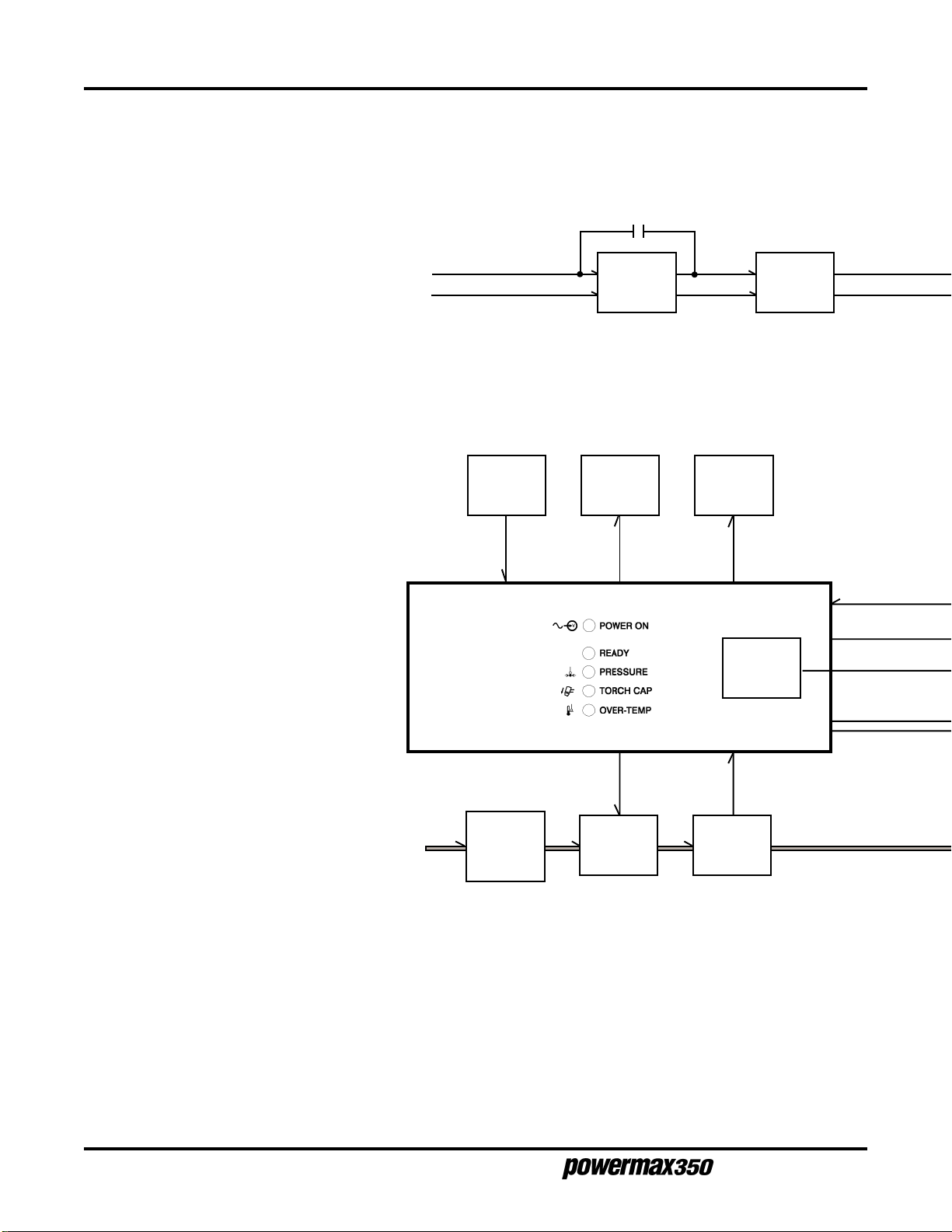
Functional Description
Refer to the functional block diagram, Figure 3-2 and the system wiring diagram Figure 3-4. Refer to Section 4,
Parts List
, to locate and identify the system components described.
Service Manual
3-3
7-98
Page 28

MAINTENANCE
1 Input Filter FL1 (CE units only)
Provides input power noise filtering.
2 Power Switch S1
Provides on/off control of power to
main transformer T1.
3 Input Voltage Selector Switch S2
Connects primary of main transformer
T1 for 115 or 230 VAC operation.
4 Fan Motor FM
Provides cooling of internal components.
5 Main Transformer T1
Supplies power to output circuit, power
control board PC1, safety control board
PC2, and fan motor FM.
6 Integrated Rectifier SR1
Changes AC output from T1 to full-wave
rectified DC.
7 Power Control Board PC1
Supplies and regulates cutting current
to torch. Also provides some timing and
control functions.
115 or 230 VAC
1 Ø Line Input
Power
1
Line Input
Filter FL1
(CE Units)
10
Thermostat
TP1
11
Resistor
11
Power-Up
Relay CR6
CR6
Input
R2
Delay
2
Power
Switch
S1
12
Contactor
Control
Relay CR7
3
Input Voltage
Selector
Switch S2
8 Safety Control Board PC2
Provides timing and control functions,
monitors safety interlocks and provides
isolation from power circuitry. Also
contains power, ready and trouble LEDs.
9 Output Control R6
Selects cutting output level.
10 Thermostat TP1
If unit overheats, TP1 opens stopping
cutting output. TP1 is located inside T1.
11 Power-Up Delay Relay CR6,
Input Resistor R2
During power-up (2-3 seconds), R2 limits
inrush current to T1. CR6 shorts out R2
after power up delay and keeps R2
shorted out while the unit is operating.
12 Contactor Control Relay CR7
Connects main transformer T1 secondary
output power to integrated rectifier SR1.
13 Air Filter/Regulator
Filters and regulates pressure of input air
supply.
14 Air Valve GS1
Allows airflow for pilot arc, cutting and
postflow.
8
Input Air Supply
70-120 psi
(4.8-8.3 bar)
Safety
Control Board
PC2
13
Air Filter/
Regulator
60 psi
(4.1bar)
14
Air
Valve
GS1
9
Output
Control
R6
15
Air Pressure
Switch
S3
15 Air Pressure Switch S3
Provides signal to PC2 to shut down unit
if air pressure is to low.
3-4
7-98
Service Manual
Page 29
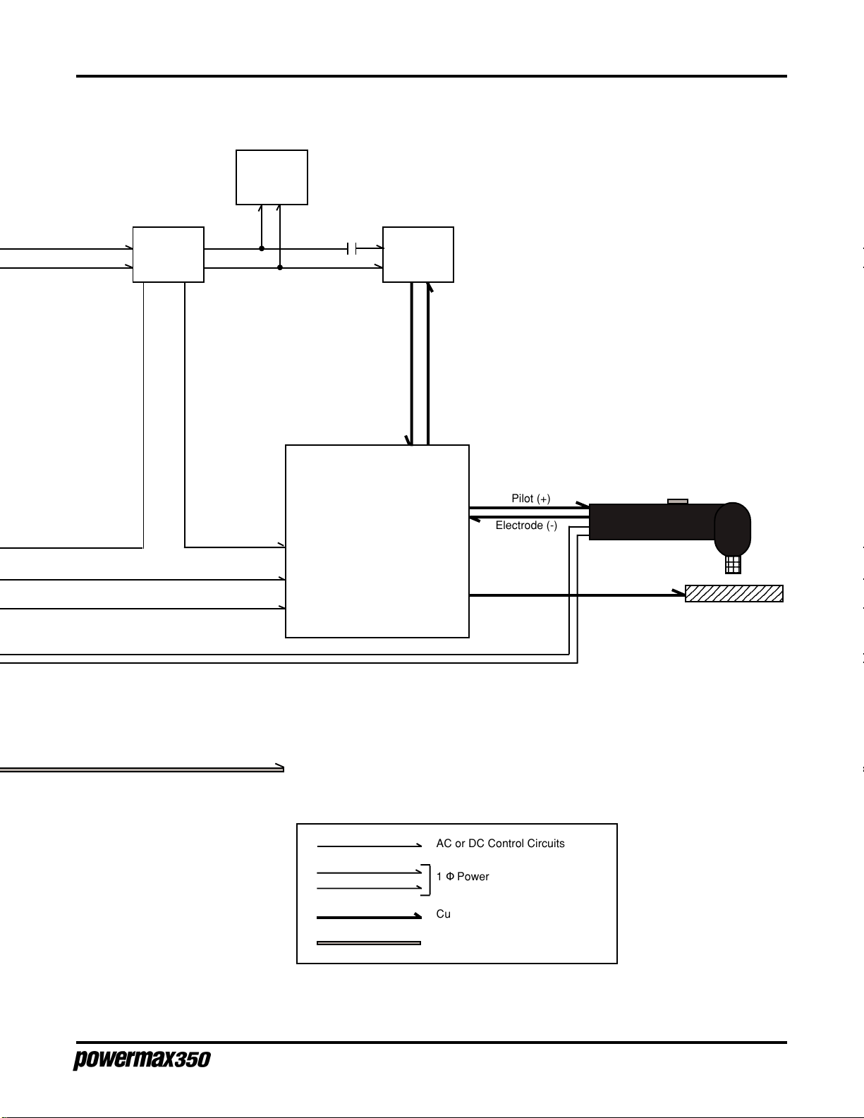
4
4
4
4
5
115
VAC
Fan
Motor
FM
115 or
230 VAC
Primary
5
Main
Transformer
T1
12
CR7
Secondary
MAINTENANCE
6
Integrated
Rectifier
SR1
Contactor Control Signal
Command Signal
Torch Trigger Circuit
Torch Cap Safety Circuit
18 and 24
VAC
36 VAC
CenterTapped
DC Power
7
Power
Control Board
PC1
Pilot (+)
Electrode (-)
Work (+)
23
23
23
2345678901234
To Torch
AC or DC Control Circuits
115 or 230 VAC 1 Φ Power
Cutting and Pilot Current Circuits
Air Supply
Figure 3-2.1 Functional Block Diagram, 115/230 Volt
Service Manual
3-5
7-98
Page 30
MAINTENANCE
1 Power Switch S1
Provides on/off control of power to
main transformer T1.
2 Main Transformer T1
Supplies power to output circuit, power
control board PC1, safety control board
PC2, and fan motor FM.
3 Fan Motor FM
Provides cooling of internal components.
4 Integrated Rectifier SR1
Changes AC output from T1 to full-wave
rectified DC.
5 Power Control Board PC1
Supplies and regulates cutting current
to torch. Also provides some timing and
control functions.
6 Safety Control Board PC2
Provides timing and control functions,
monitors safety interlocks and provides
isolation from power circuitry. Also
contains power, ready and trouble LEDs.
7 Output Control R6
Selects cutting output level.
8 Thermostat TP1
If unit overheats, TP1 opens stopping
cutting output. TP1 is located inside T1.
9 Power-Up Delay Relay CR6,
Input Resistor R2
During power-up (2-3 seconds), R2 limits
inrush current to T1. CR6 shorts out R2
after power up delay and keeps R2
shorted out while the unit is operating.
200 VAC
1 Ø Line Input
Power
6
Control Board
8
Thermostat
TP1
Safety
PC2
CR6
9
Input
Resistor
R2
9
Power-Up
Delay
Relay CR6
1
Power
Switch S1
10
Contactor
Control
Relay CR7
7
Output
Control
R6
10 Contactor Control Relay CR7
Connects main transformer T1 secondary
output power to integrated rectifier SR1.
11 Air Filter/Regulator
Filters and regulates pressure of input air
supply.
12 Air Valve GS1
Allows airflow for pilot arc, cutting and
postflow.
13 Air Pressure Switch S3
Provides signal to PC2 to shut down unit
if air pressure is to low.
3-6
7-98
Input Air Supply
70-120 psi
(4.8-8.3 bar)
11
Air Filter/
Regulator
60 psi
(4.1bar)
12
Air
Valve
GS1
13
Air Pressure
Switch
S3
Service Manual
Page 31
Primary
4
4
12345678901234
1
4
12345678901234
2
Main
Transformer
T1
3
115
VAC
Fan
Motor
FM
10
CR7
Secondary
MAINTENANCE
4
Integrated
Rectifier
SR1
18 and 24
VAC
Contactor Control Signal
Command Signal
Torch Trigger Circuit
Torch Cap Safety Circuit
36 VAC
CenterTapped
5
Power
Control Board
PC1
DC Power
Pilot (+)
Electrode (-)
Work (+)
23
23
234567890123
To Torch
AC or DC Control Circuits
1 Φ Power
Cutting and Pilot Current Circuits
Air Supply
Figure 3-2.2 Functional Block Diagram, 200 Volt
Service Manual
3-7
7-98
Page 32

MAINTENANCE
TROUBLE LED INDICATORS
If certain problems occur, the READY LED extinguishes, a trouble LED illuminates and the torch stops firing.
• PRESSURE LED - Illuminates if air pressure is below 40 psi (2.8 bar).
Turn power Off (O) and check for proper air pressure.
• TORCH CAP LED - Illuminates if the retaining cap is loose.
Turn power Off (O) and check that the retaining cap is tight. Whenever the retaining cap shutdown
system has been activated, the power must turned Off (O) and then back On (I) to reset the system.
If problems persist, complete weekly checks listed under Routine Maintenance before performing troubleshooting.
• OVER-TEMP LED - Illuminates if power supply overheats. See Duty Cycle and Overheating in the
Operation section.
3-8
7-98
Figure 3-3 Trouble LED Indicators
Service Manual
Page 33

TROUBLESHOOTING
Refer to Figure 3-4 and 3-5 to assist in the troubleshooting process.
WARNING
SHOCK HAZARD: Always turn off the power and unplug the cord or set
the line disconnect switch to Off before servicing the unit or changing
consumable parts. In the U.S., use a "lock-out / tag-out" procedure until
the service or maintenance work is complete. In other countries, follow
appropriate national or local safety procedures.
MAINTENANCE
Problem
1. No pilot arc; difficulty in establishing an arc.
Cause/Solution
1.1 Clean or replace worn consumables as
necessary.
1.2 Check for proper installation of swirl ring.
1.3 Check for damaged torch or torch lead.
1.4 Check air system for leaks.
1.5 Check coil voltage and connections of control
relay CR6. Check continuity of coil and condition
of contacts. Replace if necessary.
1.6 Check coil voltage and connections of gas valve
GS1. Check continuity of coil. Replace if
necessary.
1.7 Check integrated rectifier SR1. Replace if
necessary.
1.8 Check power control board PC1 and connections.
Replace if necessary.
2. No cutting output; POWER ON, READY,
PRESSURE, TORCH CAP and OVER-TEMP LEDs
extinguished; fan not operating.
Service Manual
1.9 Check safety control board PC2 and connections.
Replace if necessary.
2.1 Place the Power switch to On (I).
2.2 Plug in the power cord or set line disconnect
switch to On.
2.3 Check line disconnect fuses and replace if
needed or reset circuit breakers.
2.4 115/230 Volt units: Check position of input
voltage selector switch S2.
3-9
7-98
Page 34

MAINTENANCE
Problem Cause/Solution
2.5 Check resistance and connections of input
resistor R2 which is rated at 10 ohms ±10 %.
Replace if necessary.
2.6 Check coil voltage and connections of control
relay CR6. Check continuity of coil and condition
of contacts. Replace if necessary.
2.7 Check transformer T1 for signs of winding failure.
Check continuity across windings and check
connections. Check secondary voltages. Replace
if necessary.
3. No cutting output; POWER ON and READY LEDs
illuminated; PRESSURE, TORCH CAP and OVERTEMP LEDs extinguished; fan operating.
3.1 Check that the work clamp is connected.
3.2 Clean or replace worn consumables as
necessary.
3.3 Check resistance and connections of input
resistor R2 which is rated at 10 ohms ±10 %.
Replace if necessary.
3.4 Check coil voltage and connections of contactor
control relay CR7. Check continuity of coil and
condition of contacts. Replace if necessary.
3.5 Check coil voltage and connections of control
relay CR6. Check continuity of coil and condition
of contacts. Replace if necessary.
3.6 Check coil voltage and connections of gas valve
GS1. Check continuity of coil. Replace if
necessary.
3.7 Check power control board PC1 and connections.
Replace if necessary.
3.8 Check safety control board PC2 and connections.
Replace if necessary.
4. No cutting output; POWER ON LED illuminated;
READY, PRESSURE, TORCH CAP and OVER-TEMP
LEDs extinguished; fan operating.
5. No control of cutting output.
3-10
7-98
4.1 Reset power switch S1.
4.2 Check safety control board PC2 and connections.
Replace if necessary.
5.1 115/230 Volt units: Check position of input voltage
selector switch S2.
5.2 Check power control board PC1 and connections.
Replace if necessary.
5.3 Check safety control board PC2 and connections.
Replace if necessary.
Service Manual
Page 35

MAINTENANCE
Problem Cause/Solution
6. No air flow; POWER ON and READY LEDs
illuminated; PRESSURE, TORCH CAP and OVERTEMP LEDs extinguished; fan operating.
7. PRESSURE LED illuminated; READY LED
extinguished.
8. TORCH CAP LED illuminated; READY LED
extinguished.
6.1 Check air system for leaks.
6.2 Check for proper torch lead connections.
6.3 Check coil voltage and connections of gas valve
GS1. Check continuity of coil. Replace if
necessary.
6.4 Check safety control board PC2 and connections.
Replace if necessary.
7.1 Check for correct air pressure.
7.2 Check for sufficient air supply pressure.
7.3 Check air system for leaks.
7.4 Check for dirty air filter/regulator and clean, if
needed.
8.1 Check torch retaining cap to ensure it is tight.
8.2 Check for proper torch lead connections.
8.3 Check safety control board PC2 and connections.
Replace if necessary.
9. OVER-TEMP LED illuminated; READY LED
extinguished.
10. Fan not operating; POWER ON and READY LEDs
illuminated.
11. PRESSURE, TORCH CAP and OVER-TEMP
LEDs not working.
9.1 Thermostat TP1 is open (overheating). Allow the
fan to operate; the thermostat closes when the
unit has cooled.
9.2 Check transformer T1 for signs of winding failure.
Check continuity across windings and check
connections. Check secondary voltages. Replace
if necessary.
9.3 Check safety control board PC2 and connections.
Replace if necessary.
10.1 Check coil voltage and connections of fan motor
FM. Check continuity of coil. Replace if
necessary.
11.1 Check safety control board PC2 and connections.
Replace if necessary.
Service Manual
3-11
7-98
Page 36
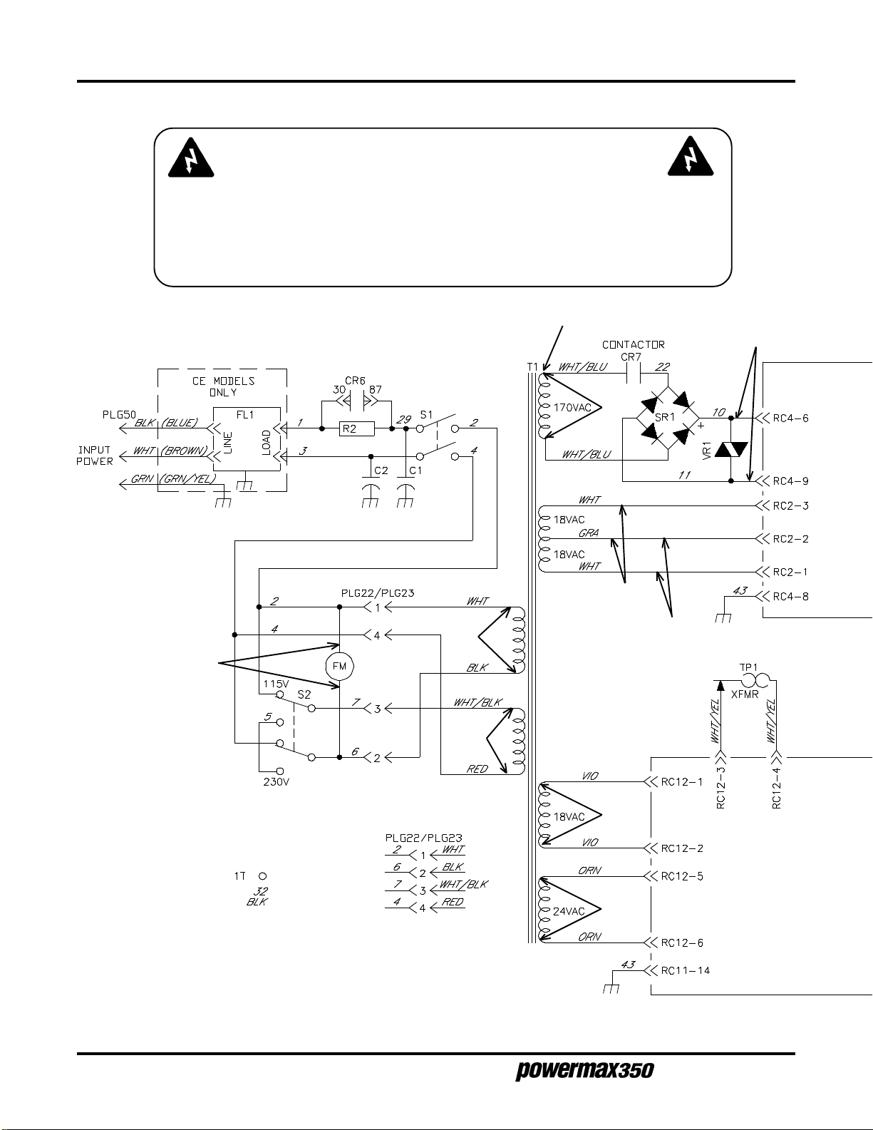
MAINTENANCE
SHOCK HAZARD: Always turn off the power and unplug the cord or set
the line disconnect switch to Off before servicing the unit or changing
consumable parts. In the U.S., use a "lock-out / tag-out" procedure until
the service or maintenance work is complete. In other countries, follow
appropriate national or local safety procedures.
WARNING
R1
V9
V4
V1
V5
V6
V2
V3
V7
V8
3-12
7-98
Service Manual
Page 37

MAINTENANCE
Resistance Values
a) Tolerance ± 10 % unless specified
b) Turn Off (O) and remove input power
plug from receptacle before checking resistance.
R1 All values for T1 are less than 1 ohm
Voltage Readings
a) Tolerance ± 10 % unless specified
b) Reference - to circuit common, lead 43 unless noted
V1, V2, V3 115 VAC
V4 170 VAC
V5, V6, V7 18 VAC
V8 24 VAC
V9 255 VDC open-circuit voltage
V10 22.5 VDC during pilot arc
V11 12 VDC
V12, V13 24 VDC
V14 255 VDC open-circuit voltage
V10
V14
Requires 40
PSI (2.8 bar)
to close S3
Power-Up
Delay Relay
V11 V12
Figure 3-4.1 Wiring Diagram, 115/230 Volt
V13
Service Manual
3-13
7-98
Page 38

MAINTENANCE
SHOCK HAZARD: Always turn off the power and unplug the cord or set
the line disconnect switch to Off before servicing the unit or changing
consumable parts. In the U.S., use a "lock-out / tag-out" procedure until
the service or maintenance work is complete. In other countries, follow
appropriate national or local safety procedures.
WARNING
V9
V4
V1
V2
V6
V5
V7
V8
R1
3-14
7-98
Service Manual
Page 39

MAINTENANCE
Resistance Values
a) Tolerance ± 10 % unless specified
b) Turn Off (O) and remove input power
plug from receptacle before checking resistance.
R1 All values for T1 are less than 1 ohm
V10
V14
Voltage Readings
a) Tolerance ± 10 % unless specified
b) Reference - to circuit common, lead 43 unless noted
V1 115 VAC
V2 200 VAC
V4 170 VAC
V5, V6, V7 18 VAC
V8 24 VAC
V9 265 VDC open-circuit voltage
V10 22.5 VDC during pilot arc
V11 12 VDC
V12, V13 24 VDC
V14 265 VDC open-circuit voltage
Requires 40
PSI (2.8 bar)
to close S3
Power-Up
Delay Relay
V11
V12
V13
Figure 3-4.2 Wiring Diagram, 200 Volt
Service Manual
3-15
7-98
Page 40

MAINTENANCE
PLG10
36A 37A
4
3
35A 38A
2A
29A
6A
6B
2
1
C1
5A 5A
4C
4B
To PC2-RC10
S1
4A
3A
C2
To
Power
Cord
3A
1A
S2
7A
2B
2C
2D
27A
2B
4A
29A
3A
To Base
Ground
2B
2C
6A
2D
5A
7A
4C
6B
4A
5A
29A
37A
38A
35A
36A
CR6
To Torch Cap
Switch
To Torch Trigger
28A
R2
43A
To Base
Ground
To T1-PLG23
1
2C
2
6A
7A
3
4C
4
2D
6B
To Fan
Motor
3-16
7-98
Service Manual
Page 41

MAINTENANCE
Figure 3-5.1 Wiring Harness Diagram, 115/230 Volt
Service Manual
3-17
7-98
Page 42
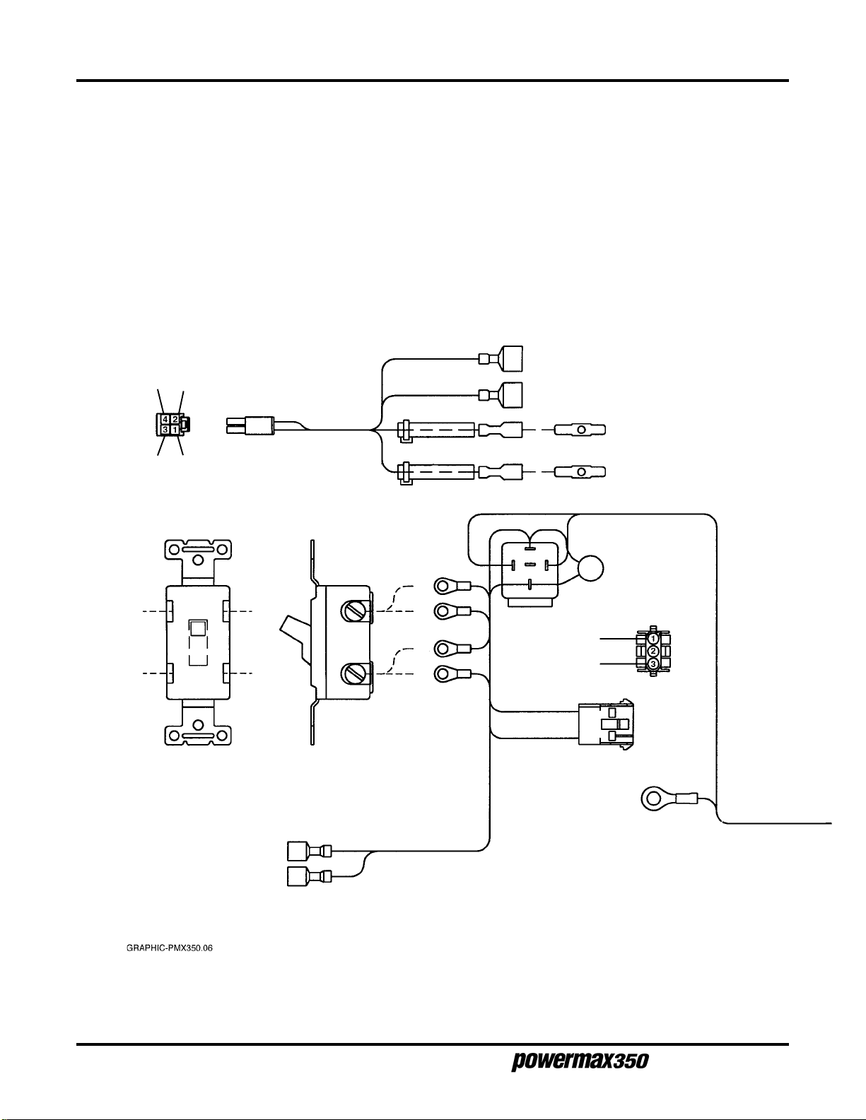
MAINTENANCE
36A 37A
35A 38A
PLG10
To PC2-RC10
38A
To Torch Cap Switch
37A
35A
To Torch Trigger
36A
2B
29A
LOAD
LINE
To
Power
Cord
4B
3A
S1
3A
1A
2B
4B
29A
3A
27A
29A
28A
R2
1A
CR6
2B
4A
PLG22
43A
To Base
Ground
3-18
7-98
Service Manual
Page 43

To R1
21A
To SR1 Pos To SR1 Neg
10A
11A
To R1
20A
23A
23B
To Torch Electrode
25A
To Torch Pilot
MAINTENANCE
25A
20A
10A
11A
21A
24A
23A
VR1
22A
To SR1 AC
32A 32B
To 1T
To S3
8A 9A
22A
To CR1
43B
To Center
Baffle Ground
To GS1
15A 14A
31A
30A
30A
17A
16A
19A
216
115
014
93
82
71
PLG1
To PC1-RC1
26A
31A
18A
32B
32A
13A
26A
28A
8A
43A
14A
12A
43B
To PC1-RC4
0201
919
818
717
616
515
414
313
212
111
PLG4
PLG6
To PC1-RC6
15A
19A
17A
18A
16A
9A
27A
Figure 3-5.2 Wiring Harness Diagram, 200 Volt
Service Manual
PLG11
To PC2-RC11
12A 13A
To CR7
3-19
7-98
Page 44

MAINTENANCE
PAC110 TORCH REPAIR
Parts and Required Tools
The PAC110 torch can be repaired in the field by removing the torch main body from the torch assembly and
installing a new torch main body and a plastic cinch strap (Tyrap). To perform the repair, the following customersupplied tools are required:
• #1 Phillips-head screwdriver
• 7/16 inch (11 mm) open-end wrench
• Wire cutters
• Crimping tool
WARNING
SHOCK HAZARD: Always turn off the power and unplug the cord or set the line disconnect
switch to Off before servicing the unit or changing consumable parts. In the U.S., use a "lockout / tag-out" procedure until the service or maintenance work is complete. In other countries,
follow appropriate national or local safety procedures.
Torch Main Body Removal and Replacement
To disassemble and repair the torch, refer to Figure 3-6 and perform the following procedure:
1. Remove the 5 screws which secure the handle halves together.
2. Remove the torch main body and torch switch from the handle halves.
3. Cut and remove the cinch strap (Tyrap).
4. Cut the 4 white wires connecting the torch lead to the plunger. Cut the wires at the butt splice.
5. Cut the 2 blue wires connecting the torch lead to the microswitch. Cut the wires at the butt splices.
6. Cut the 2 red wire connecting the torch lead to the pilot arc lead. Cut the wire at the butt splice.
7. Disconnect the torch main body and torch lead gas fitting using the 7/16 inch open-end wrench.
To install the new torch, reverse the removal procedure:
1. While holding the torch main body to keep the wires from twisting, connect the body assembly and the torch
lead gas fitting using the 7/16 inch open-end wrench.
2. Connect the 2 red wire from the torch lead to the butt splice connecting the red wire to the pilot arc fitting
using the crimping tool.
3. Connect the 2 blue wires from the torch lead to the butt splices connecting the white wires to the microswitch
using the crimping tool.
4. Connect the 4 white wires from the torch lead to the butt splice connecting the black plunger wire to the torch
main body using the crimping tool.
3-20
7-98
Service Manual
Page 45
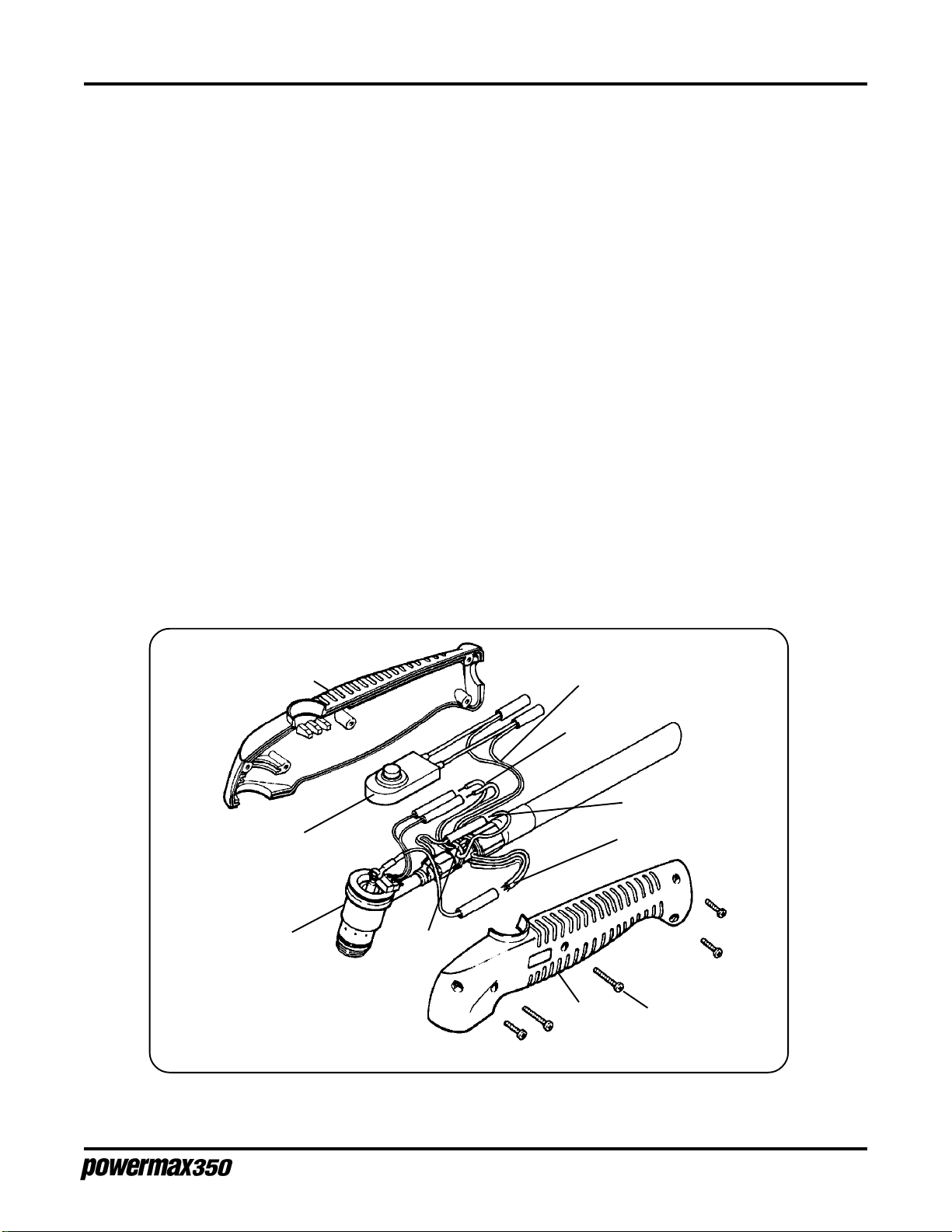
MAINTENANCE
5. Install the new cinch strap (Tyrap) as shown.
6. Install the torch main body assembly and torch switch into one of the handle halves. While positioning the
handle halves together, be careful not to pinch any wires, especially around the torch switch retainers.
7. Replace the 5 screws to secure the handle halves together. If the seams do not fit together tightly, remove
the screws and check for pinched wires.
Torch Switch Removal and Replacement
To disassemble and repair the torch, refer to Figure 3-6 and perform the following procedure.
1. Remove the 5 screws that secure the handle halves together.
2. Remove the torch switch from the handle.
3. Remove the torch switch by cutting the 2 splices at the torch lead (violet wires).
4. Replace the torch switch by crimping the switch wires and the violet wires from the torch lead together with
the splices.
5. Install the torch switch back into the handle. While positioning the handle halves together, be careful not to
pinch any wires, especially around the torch switch retainers.
6. Replace the 5 screws to secure the handle halves together.
Torch Switch
Torch Main Body
Handle
Tyrap
Violet Wires (2)
Blue
Wires (2)
Red Wires (2)
White Wires (4)
Figure 3-6 PAC110 Torch Repair
Service Manual
Handle
Screws (5)
3-21
7-98
Page 46

MAINTENANCE
TECHNICAL QUESTIONS
If you are unable to fix the problem with your Powermax350 by following this basic troubleshooting guide or if you
need further assistance:
1. Call your distributor, who will be able to help you, or refer you to an authorized Hypertherm repair facility.
2. Call Hypertherm Technical Service or the nearest Hypertherm office listed in the front of this manual.
3-22
7-98
Service Manual
Page 47

PARTS LIST
Section 4 PARTS LIST
In this section:
115/230 Volt Power Supply .............................................................................. 4-2
200 Volt Power Supply ..................................................................................... 4-4
PAC110 Torch Assembly and Leads ................................................................ 4-6
Consumable Parts............................................................................................ 4-7
Service Manual
4-1
7-98
Page 48

PARTS LIST
115/230 VOLT POWER SUPPLY
Index No. Part No. Description Ref. Desig. Quantity
1 060074 Varistor VR1 1
2 060044 Rectifier, integ 40A 800V SR1 1
3 060052 Heat Sink - 1
4 060042 Insulator, end - 2
5 060043 Bracket, resistor - 1
6 060049 Resistor, wire wound, fixed 338W 1.5 ohm R1 1
7 060015 Stand-Off Support PC card - 4
8 060065 Switch, Pressure 40 psi fixed S3 1
9 060055 Fitting, plastic qdisc elbow 1/4 NPT x 1/4 OD tubing - 2
10 060063 Fitting, pipe brass tee 1/8 NPT - 1
11 060064 Fitting, pipe brass nipple 1/8 NPT - 1
12 060062 Fitting, pipe brass elbow ST 1/4 NPT - 1
13 060066 Fitting, pipe brass nipple L 1/4 NPT x 2.5 - 1
14 060067 Fitting, pipe brass coupling 1/4 NPT - 1
15 060033 Fitting, pipe stainless qdisc M 1/4 NPT (in consum. box) - 1
060059 Fitting, pipe brass plug schnd 1/4 NPT - 1
16 015540 Gasket, neoprene - 1
17 060057 Bracket, mounting air filter/regulator - 1
18 060058 Gauge, pressure 0-160 psi 1/8 NPT - 1
19 060056 Regulator/Filter, 250 psig in 100 psig max out - 1
20 060060 Fitting, pipe brass barbed female 3/16 tbg 1/8 NPT - 1
21 060001 Baffle, center - 1
Insulator, edge trim - 1
Bushing, snap in - 1
22 060019 Stand-off, 6-32 x .437 long - 3
23 060040 Assembly, circuit card, power control PC1 1
24 060003 Handle, lifting - 1
25 060002 Cover - 1
26 060028 Box, consumable storage - 1
060027 Shelf, consumable box storage - 1
060029 Door, consumable box storage - 1
060030 Catch, consumable storage - 1
060031 Hinge, consumable storage - 1
27 060075 Switch, toggle, DPST, 40A 600V S1 1
060034 Gasket, switch - 1
28 060076 Relay, enclosed, 12 VDC SPST CR6 1
29 060000 Case Section, base/back/front - 1
30 060014 Connector, cable clamp .750 - 1
31 060012 Cable, power 10 ft. 14 gauge 3/C PLG50 1
060013 Cable, power 10 ft. 14 gauge 3/C (CE) PLG50 1
32 060006 Fan, motor 115V 50/60 Hz 3100 RPM FM 1
33 060007 Transformer, power main 115/230V T1 1
060008 Transformer, power main 115/230V (CE) T1 1
34 060004 Mount, neoprene - 6
35 060011 Bushing, strain relief .455/.629 ID x 1.115 mtg - 1
36 060009 Cable, work 15 ft. 12 gauge with clamp - 1
37 060010 Bushing, strain relief .500 ID x .455 mtg hole - 1
38 060016 Knob, pointer PowerMax - 1
39 060041 Assembly, circuit card, safety control PC2 1
40 060018 Stand-Off Support PC card - 4
41 060080 Bracket, switch - 1
42 060079 Switch, toggle DPDT 15A 125 VAC S2 1
43 060078 Thermistor, PTC 8A 250V R2 1
44 060070 Assembly, capacitor C1, C2 1
45 060053 Valve, 24 VAC 3-way 1/8 NPT 5/32 orifice 100 psi GS1 1
060024 Tubing, pneumatic .250 OD x .170 ID x 13.5 inches - 1
46 060054 Fitting, pipe brass adapter 1/8 NPT - 1
47 060005 Contactor, def prp 25A 1P 24V CR7 1
4-2
7-98
Service Manual
Page 49
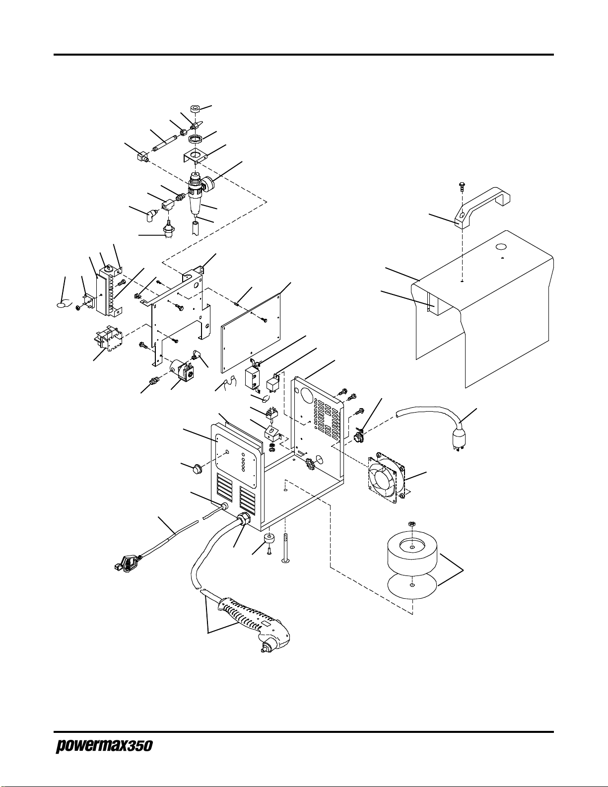
PARTS LIST
9
16
20
19
19
21
17
18
22
24
25
23
26
27
28
29
15
14
13
12
11
10
9
8
5
4
3
1
2
47
6
7
46
36
PAC110 Torch
See Figure 4-2
45
38
39
37
44
40
35
43
42
41
30
31
32
(fan mounted to
blow inward)
34
33
Figure 4-1.1 115/230 Volt Powermax350 Power Supply
Service Manual
4-3
7-98
Page 50

PARTS LIST
200 VOLT POWER SUPPLY
Index No. Part No. Description Ref. Desig. Quantity
1 060074 Varistor VR1 1
2 060044 Rectifier, integ 40A 800V SR1 1
2.1 060129 Thermostat, NC open 70C - 1
3 060052 Heat Sink - 1
4 060042 Insulator, end - 2
5 060043 Bracket, resistor - 1
6 060049 Resistor, wire wound, fixed 338W 1.5 ohm R1 1
7 060015 Stand-Off Support PC card - 4
8 060065 Switch, Pressure 40 psi fixed S3 1
9 060055 Fitting, plastic qdisc elbow 1/4 NPT x 1/4 OD tubing - 2
10 060063 Fitting, pipe brass tee 1/8 NPT - 1
11 060064 Fitting, pipe brass nipple 1/8 NPT - 1
12 060062 Fitting, pipe brass elbow ST 1/4 NPT - 1
13 060066 Fitting, pipe brass nipple L 1/4 NPT x 2.5 - 1
14 060067 Fitting, pipe brass coupling 1/4 NPT - 1
15 060033 Fitting, pipe stainless qdisc M 1/4 NPT (in consum. box) - 1
060059 Fitting, pipe brass plug schnd 1/4 NPT - 1
16 015540 Gasket, neoprene - 1
17 060057 Bracket, mounting air filter/regulator - 1
18 060058 Gauge, pressure 0-160 psi 1/8 NPT - 1
19 060056 Regulator/Filter, 250 psig in 100 psig max out - 1
20 060060 Fitting, pipe brass barbed female 3/16 tbg 1/8 NPT - 1
21 060001 Baffle, center - 1
Insulator, edge trim - 1
Bushing, snap in - 1
22 060019 Stand-off, 6-32 x .437 long - 3
23 060040 Assembly, circuit card, power control PC1 1
24 060003 Handle, lifting - 1
25 060002 Cover - 1
26 060028 Box, consumable storage - 1
060027 Shelf, consumable box storage - 1
060029 Door, consumable box storage - 1
060030 Catch, consumable storage - 1
060031 Hinge, consumable storage - 1
27 060075 Switch, toggle, DPST, 40A 600V S1 1
060034 Gasket, switch - 1
28 060076 Relay, enclosed, 12 VDC SPST CR6 1
29 060000 Case Section, base/back/front - 1
30 060014 Connector, cable clamp .750 - 1
31 060013 Cable, power 10 ft. 14 gauge 3/C PLG50 1
32 060006 Fan, motor 115V 50/60 Hz 3100 RPM FM 1
33 060125 Transformer, power main 200V T1 1
34 060004 Mount, neoprene - 6
35 060011 Bushing, strain relief .455/.629 ID x 1.115 mtg - 1
36 060009 Cable, work 15 ft. 12 gauge with clamp - 1
37 060010 Bushing, strain relief .500 ID x .455 mtg hole - 1
38 060016 Knob, pointer PowerMax - 1
39 060041 Assembly, circuit card, safety control PC2 1
40 060018 Stand-Off Support PC card - 4
41 – –
42 ––
43 060078 Thermistor, PTC 8A 250V R2 1
44 ––
45 060053 Valve, 24 VAC 3-way 1/8 NPT 5/32 orifice 100 psi GS1 1
060024 Tubing, pneumatic .250 OD x .170 ID x 13.5 inches - 1
46 060054 Fitting, pipe brass adapter 1/8 NPT - 1
47 060005 Contactor, def prp 25A 1P 24V CR7 1
4-4
7-98
Service Manual
Page 51
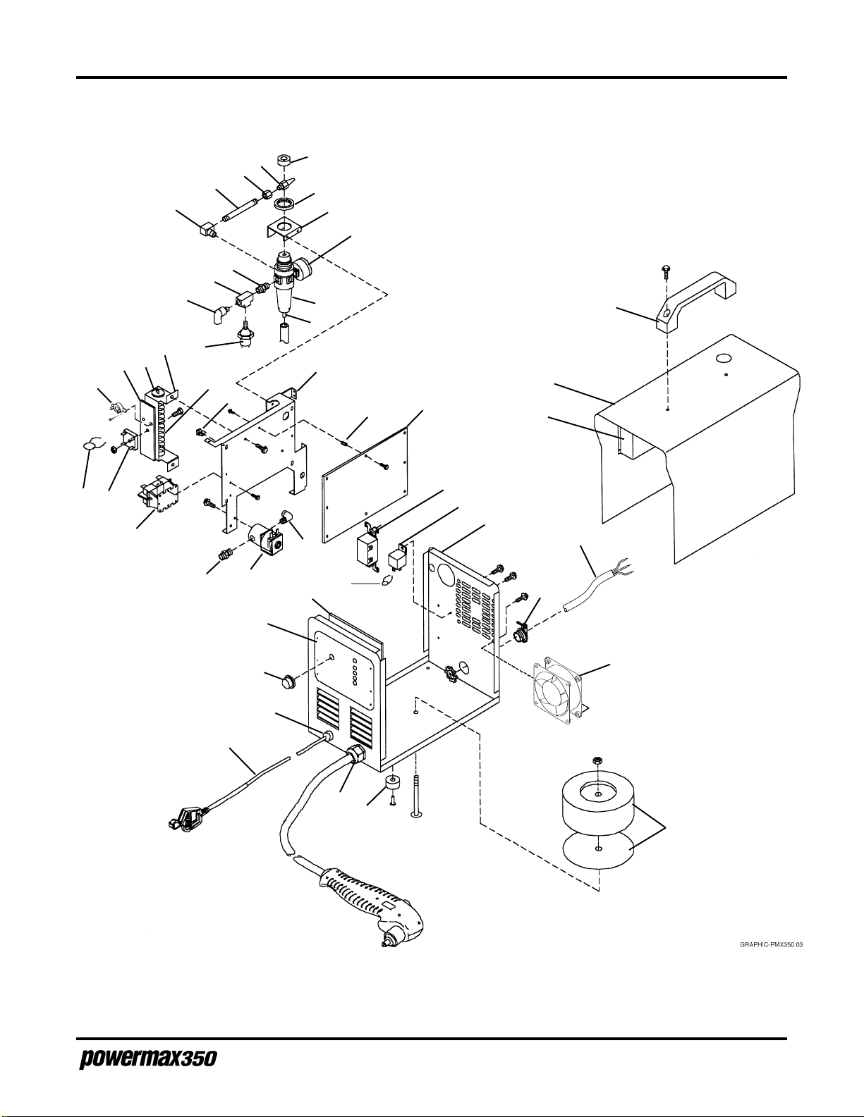
PARTS LIST
9
16
20
19
19
21
17
18
22
23
24
25
26
27
28
29
31
15
14
13
12
11
10
9
8
5
4
3
2.1
1
2
47
6
7
46
36
45
38
39
37
40
35
43
30
32
(fan mounted to
blow inward)
34
33
Figure 4-1.2 200 Volt Powermax350 Power Supply
Service Manual
4-5
7-98
Page 52

PARTS LIST
PAC110 Torch Assembly
Index No. Part No. Description Quantity
070057 Torch Assembly with 15 ft (4.5 m) Lead
070058 Torch Assembly with 25 ft (7.6 m) Lead
1 001192 Handle, PAC110 1
2 075339 Screws, P/S, # 4 X 1/2, PH, RND, S/B 3
3 075341 Screws, P/S, # 4 X 3/4, PH, RND, S/B 2
4 005094 Switch, Torch Pushbutton 1
5 020588 Torch Main Body with Micro-Switch, PAC110 1
6 044016 O-Ring: BUNA 90 Duro .614X.070 1
7 029241 Torch Lead, 15 ft (4.5 m) 1
7 029257 Torch Lead, 25 ft (7.6 m) 1
1
)
4
7
)
5
2
6
1
2
Figure 4-2 PAC110 Torch Assembly and Torch Leads
3
4-6
7-98
Service Manual
Page 53

PARTS LIST
CONSUMABLE PARTS
Index No. Part No. Description Quantity
1 020239 Ring, Swirl 1
2 020382 Electrode, Extended 1
3 120504 Nozzle, Extended, 25A 1
4 020218 Cap, Retaining 1
The consumable parts are found in a box, located in the left side of the power supply cover.
4
3
Figure 4-3 Consumable Parts
2
1
Service Manual
4-7
7-98
 Loading...