


®
Powermax30 AIR
Plasma Arc Cutting System with Integrated Air Compressor
Operator Manual
808840 | Revision 1 | English

Register your new Hypertherm system
Register your product online at www.hypertherm.com/registration for easier technical
and warranty support. You can also receive updates on new Hypertherm products and a free
gift as a token of our appreciation.
For your records
Serial number:________________________________________________________________
Purchase date: _______________________________________________________________
Distributor: __________________________________________________________________
____________________________________________________________________________
____________________________________________________________________________
Maintenance notes:
____________________________________________________________________________
____________________________________________________________________________
____________________________________________________________________________
____________________________________________________________________________
____________________________________________________________________________
____________________________________________________________________________
Powermax and Hypertherm are trademarks of Hypertherm Inc. and may be registered in the United States and other countries. All
other trademarks are the property of their respective holders.
© 2015 Hypertherm Inc.

Powermax30 AIR
Operator Manual
808840
Revision 1
English
February 2015
Hypertherm Inc.
Hanover, NH 03755 USA
www.hypertherm.com

Hypertherm Inc.
Etna Road, P.O. Box 5010
Hanover, NH 03755 USA
603-643-3441 Tel (Main Office)
603-643-5352 Fax (All Departments)
info@hypertherm.com (Main Office Email)
800-643-9878 Tel (Technical Service)
technical.service@hypertherm.com (Technical Service Email)
800-737-2978 Tel (Customer Service)
customer.service@hypertherm.com (Customer Service Email)
866-643-7711 Tel (Return Materials Authorization)
877-371-2876 Fax (Return Materials Authorization)
return.materials@hypertherm.com (RMA email)
Hypertherm Plasmatechnik GmbH
Technologiepark Hanau
Rodenbacher Chaussee 6
D-63457 Hanau-Wolfgang, Deutschland
49 6181 58 2100 Tel
49 6181 58 2134 Fax
49 6181 58 2123 (Technical Service)
Hypertherm (S) Pte Ltd.
82 Genting Lane
Media Centre
Annexe Block #A01-01
Singapore 349567, Republic of Singapore
65 6841 2489 Tel
65 6841 2490 Fax
65 6841 2489 (Technical Service)
Hypertherm (Shanghai) Trading Co., Ltd.
Unit 301, South Building
495 ShangZhong Road
Shanghai, 200231
PR China
86-21-60740003 Tel
86-21-60740393 Fax
Hypertherm Europe B.V.
Vaartveld 9
4704 SE
Roosendaal, Nederland
31 165 596907 Tel
31 165 596901 Fax
31 165 596908 Tel (Marketing)
31 165 596900 Tel (Technical Service)
00 800 4973 7843 Tel (Technical Service)
Hypertherm Japan Ltd.
Level 9, Edobori Center Building
2-1-1 Edobori, Nishi-ku
Osaka 550-0002 Japan
81 6 6225 1183 Tel
81 6 6225 1184 Fax
Hypertherm Brasil Ltda.
Rua Bras Cubas, 231 – Jardim Maia
Guarulhos, SP - Brasil
CEP 07115-030
55 11 2409 2636 Tel
55 11 2408 0462 Fax
Hypertherm México, S.A. de C.V.
Avenida Toluca No. 444, Anexo 1,
Colonia Olivar de los Padres
Delegación Álvaro Obregón
México, D.F. C.P. 01780
52 55 5681 8109 Tel
52 55 5683 2127 Fax
Hypertherm Korea Branch
#3904 Centum Leaders Mark B/D,
1514 Woo-dong, Haeundae-gu, Busan
Korea, 612-889
82 51 747 0358 Tel
82 51 701 0358 Fax
WARNING!
READ THE SAFETY INFORMATION
Before operating or maintaining any Hypertherm equipment, read the
Safety and Compliance Manual (80669C) for important safety information.
You can find the Safety and Compliance Manual in the “Downloads library”
at www.hypertherm.com
.


Contents
Electromagnetic Compatibility (EMC) ............................................................................ SC-11
Introduction ..............................................................................................................................................................................SC-11
Installation and use .................................................................................................................................................................SC-11
Assessment of area ................................................................................................................................................................SC-11
Methods of reducing emissions ..........................................................................................................................................SC-11
Mains supply ....................................................................................................................................................................SC-11
Maintenance of cutting equipment .....................................................................................................................................SC-12
Cutting cables .........................................................................................................................................................................SC-12
Equipotential bonding ....................................................................................................................................................SC-12
Earthing of the workpiece .............................................................................................................................................SC-12
Screening and shielding .......................................................................................................................................................SC-12
Warranty .................................................................................................................................. SC-13
Attention ....................................................................................................................................................................................SC-13
General .....................................................................................................................................................................................SC-13
Patent indemnity .....................................................................................................................................................................SC-14
Limitation of liability ................................................................................................................................................................SC-14
National and local codes .......................................................................................................................................................SC-14
Liability cap ..............................................................................................................................................................................SC-14
Insurance ..................................................................................................................................................................................SC-14
Transfer of rights .....................................................................................................................................................................SC-14
1 Specifications .............................................................................................................................. 15
Safety information ......................................................................................................................................................................... 15
System description ....................................................................................................................................................................... 15
Power supply dimensions ........................................................................................................................................................... 16
System weights ............................................................................................................................................................................. 16
Hypertherm system ratings ......................................................................................................................................................... 17
Powermax30 AIR Operator Manual 808840 7

Contents
Torch dimensions ......................................................................................................................................................................... 18
Torch weight .................................................................................................................................................................................. 18
Cutting specifications .................................................................................................................................................................. 19
IEC symbols ................................................................................................................................................................................... 20
Noise levels .................................................................................................................................................................................... 20
Symbols and marks ...................................................................................................................................................................... 21
2 Power Supply Setup .................................................................................................................. 23
Unpack the plasma system ........................................................................................................................................................ 23
Claims ...................................................................................................................................................................................... 23
System contents ........................................................................................................................................................................... 24
Position the plasma cutting system .......................................................................................................................................... 25
Prepare the electrical power ...................................................................................................................................................... 25
Voltage configurations ......................................................................................................................................................... 25
Requirements for grounding .............................................................................................................................................. 27
Power cord considerations ........................................................................................................................................................ 27
CSA power cords and plugs ............................................................................................................................................. 27
CE power cords .................................................................................................................................................................... 28
Install a plug on the power cord ................................................................................................................................ 28
Extension cord recommendations ..................................................................................................................................... 29
Generator recommendations ............................................................................................................................................. 29
3 Torch Setup .................................................................................................................................. 31
Introduction .................................................................................................................................................................................... 31
Hand torch components ..................................................................................................................................................... 31
Consumable life ............................................................................................................................................................................ 32
Consumable use ........................................................................................................................................................................... 33
Using the cut charts ............................................................................................................................................................. 33
Consumable set .................................................................................................................................................................... 34
240 V / 30 A cutting .................................................................................................................................................... 35
120 V / 20 A cutting .................................................................................................................................................... 37
8 Powermax30 AIR Operator Manual 808840

Contents
4 Operation ...................................................................................................................................... 39
Controls and indicators ............................................................................................................................................................... 39
Rear controls .......................................................................................................................................................................... 39
Front panel controls and indicator LED symbols ........................................................................................................... 40
Operate the plasma system ....................................................................................................................................................... 41
Step 1 – Install the consumables ..................................................................................................................................... 41
Step 2 – Connect the electrical power ........................................................................................................................... 42
Step 3 – Adjust the output current ................................................................................................................................... 43
Operating the system on a 120 V / 20 A circuit ................................................................................................... 43
Operating the system on a 240 V / 20 A circuit ................................................................................................... 43
Decrease output current for lower-rated power plugs ......................................................................................... 43
Cutting expanded metal .............................................................................................................................................. 43
Step 4 – Attach the ground clamp ................................................................................................................................... 44
Step 5 – Power ON the system ........................................................................................................................................ 44
Step 6 – Check the indicator LEDs ................................................................................................................................. 45
Step 7 – Make sure the system is ready, and start cutting ........................................................................................ 45
What to expect during and after cutting ................................................................................................................................. 45
Postflow .................................................................................................................................................................................. 45
Internal compressor and fan activity ................................................................................................................................. 45
Water under the power supply .......................................................................................................................................... 45
Understand duty-cycle limitations ............................................................................................................................................. 46
System operation guidelines ...................................................................................................................................................... 47
Hand torch operation ................................................................................................................................................................... 48
Safety catch operation ......................................................................................................................................................... 48
Hand torch cutting guidelines ............................................................................................................................................ 49
Recommendations for cutting at 120 V ................................................................................................................... 49
Edge start on a workpiece .................................................................................................................................................. 50
Pierce a workpiece ............................................................................................................................................................... 51
Common hand-cutting faults .............................................................................................................................................. 52
Minimizing dross ............................................................................................................................................................ 52
Powermax30 AIR Operator Manual 808840 9

Contents
5 Maintenance and Troubleshooting ....................................................................................... 53
Perform routine maintenance ..................................................................................................................................................... 53
Inspect the consumables ............................................................................................................................................................ 55
Basic troubleshooting .................................................................................................................................................................. 56
Power LED faults .................................................................................................................................................................. 56
Temperature LED faults ....................................................................................................................................................... 57
Internal compressor LED faults ......................................................................................................................................... 58
Torch LED faults ................................................................................................................................................................... 59
Common cutting issues ...................................................................................................................................................... 60
6 Parts ............................................................................................................................................... 61
Power supply parts ...................................................................................................................................................................... 62
Exterior, front .......................................................................................................................................................................... 62
Exterior, rear ........................................................................................................................................................................... 63
Hand torch consumables ............................................................................................................................................................ 64
Accessory parts ............................................................................................................................................................................ 65
Power supply labels ..................................................................................................................................................................... 66
Consumables label ............................................................................................................................................................... 66
CSA warning label ............................................................................................................................................................... 67
CE warning label ................................................................................................................................................................... 68
10 Powermax30 AIR Operator Manual 808840

Electromagnetic Compatibility (EMC)
Introduction
Hypertherm’s CE-marked equipment is built in compliance
with standard EN60974-10. The equipment should be
installed and used in accordance with the information
below to achieve electromagnetic compatibility.
The limits required by EN60974-10 may not be adequate
to completely eliminate interference when the affected
equipment is in close proximity or has a high degree of
sensitivity. In such cases it may be necessary to use other
measures to further reduce interference.
This cutting equipment is designed for use only in an
industrial environment.
Installation and use
The user is responsible for installing and using the plasma
equipment according to the manufacturer’s instructions.
If electromagnetic disturbances are detected then it shall
be the responsibility of the user to resolve the situation
with the technical assistance of the manufacturer. In some
cases this remedial action may be as simple as earthing
the cutting circuit, see Earthing of the work piece. In other
cases, it could involve constructing an electromagnetic
screen enclosing the power source and the work
complete with associated input filters. In all cases,
electromagnetic disturbances must be reduced to the
point where they are no longer troublesome.
Assessment of area
Before installing the equipment, the user shall make an
assessment of potential electromagnetic problems in the
surrounding area. The following shall be taken into
account:
a. Other supply cables, control cables, signaling
and telephone cables; above, below and adjacent
to the cutting equipment.
b. Radio and television transmitters and receivers.
c. Computer and other control equipment.
d. Safety critical equipment, for example guarding of
industrial equipment.
e. Health of the people around, for example the use
of pacemakers and hearing aids.
f. Equipment used for calibration or measurement.
g. Immunity of other equipment in the environment.
User shall ensure that other equipment being
used in the environment is compatible. This may
require additional protection measures.
h. Time of day that cutting or other activities are to
be carried out.
The size of the surrounding area to be considered will
depend on the structure of the building and other activities
that are taking place. The surrounding area may extend
beyond the boundaries of the premises.
Methods of reducing emissions
Mains supply
Cutting equipment must be connected to the mains
supply according to the manufacturer’s recommendations.
If interference occurs, it may be necessary to take
additional precautions such as filtering of the mains
supply.
Consideration should be given to shielding the supply
cable of permanently installed cutting equipment, in
metallic conduit or equivalent. Shielding should be
electrically continuous throughout its length. The shielding
should be connected to the cutting mains supply so that
good electrical contact is maintained between the conduit
and the cutting power source enclosure.
Safety and Compliance SC-11

Electromagnetic Compatibility (EMC)
Maintenance of cutting equipment
The cutting equipment must be routinely maintained
according to the manufacturer’s recommendations. All
access and service doors and covers should be closed
and properly fastened when the cutting equipment is in
operation. The cutting equipment should not be modified
in any way, except as set forth in and in accordance with
the manufacturer’s written instructions. For example, the
spark gaps of arc striking and stabilizing devices should
be adjusted and maintained according to the
manufacturer’s recommendations.
Cutting cables
The cutting cables should be kept as short as possible
and should be positioned close together, running at or
close to the floor level.
Equipotential bonding
Bonding of all metallic components in the cutting
installation and adjacent to it should be considered.
Earthing of the workpiece
Where the workpiece is not bonded to earth for electrical
safety, nor connected to earth because of its size and
position, for example, ship’s hull or building steel work, a
connection bonding the workpiece to earth may reduce
emissions in some, but not all instances. Care should be
taken to prevent the earthing of the workpiece increasing
the risk of injury to users, or damage to other electrical
equipment. Where necessary, the connection of the
workpiece to earth should be made by a direct connection
to the workpiece, but in some countries where direct
connection is not permitted, the bonding should be
achieved by suitable capacitances selected according to
national regulations.
Note: The cutting circuit may or may not be earthed for
safety reasons. Changing the earthing arrangements
should only be authorized by a person who is competent
to assess whether the changes will in crease the risk of
injury, for example, by allowing parallel cutting current
return paths which may damage the earth circuits of other
equipment. Further guidance is provided in IEC 60974-9,
Arc Welding Equipment, Part 9: Installation and Use.
However, metallic components bonded to the workpiece
will increase the risk that the operator could receive a
shock by touching these metallic components and the
electrode (nozzle for laser heads) at the same time.
The operator should be insulated from all such bonded
metallic components.
Screening and shielding
Selective screening and shielding of other cables and
equipment in the surrounding area may alleviate problems
of interference. Screening of the entire plasma cutting
installation may be considered for special applications.
SC-12 Safety and Compliance

Warranty
Attention
Genuine Hypertherm parts are the factory-recommended
replacement parts for your Hypertherm system. Any
damage or injury caused by the use of other than genuine
Hypertherm parts may not be covered by the Hypertherm
warranty, and will constitute misuse of the Hypertherm
Product.
You are solely responsible for the safe use of the Product.
Hypertherm does not and cannot make any guarantee or
warranty regarding the safe use of the product in your
environment.
General
Hypertherm, Inc. warrants that its Products shall be free
from defects in materials and workmanship for the specific
periods of time set forth herein and as follows: if
Hypertherm is notified of a defect (i) with respect to the
plasma power supply within a period of two (2) years from
the date of its delivery to you, with the exception of
Powermax brand power supplies, which shall be within a
period of three (3) years from the date of delivery to you,
and (ii) with respect to the torch and leads within a period
of one (1) year from its date of delivery to you, and with
respect to torch lifter assemblies within a period of one (1)
year from its date of delivery to you, and with respect to
Automation products one (1) year from its date of delivery
to you, with the exception of the EDGE Pro CNC,
EDGE Pro Ti CNC, MicroEDGE Pro CNC, and
ArcGlide THC, which shall be within a period of two (2)
years from the date of delivery to you, and (iii) with respect
to HyIntensity fiber laser components within a period of
two (2) years from the date of its delivery to you, with the
exception of laser heads and beam delivery cables, which
shall be within a period of one (1) year from its date of
delivery to you.
Hypertherm provides repair, replacement or adjustment of
the Product as the sole and exclusive remedy, if and only if
the warranty set forth herein properly is invoked and
applies. Hypertherm, at its sole option, shall repair,
replace, or adjust, free of charge, any defective Products
covered by this warranty which shall be returned with
Hypertherm’s prior authorization (which shall not be
unreasonably withheld), properly packed, to Hypertherm’s
place of business in Hanover, New Hampshire, or to an
authorized Hypertherm repair facility, all costs, insurance
and freight prepaid by the customer. Hypertherm shall not
be liable for any repairs, replacement, or adjustments of
Products covered by this warranty, except those made
pursuant to this paragraph and with Hypertherm’s prior
written consent.
The warranty set forth above is exclusive and is in lieu of all
other warranties, express, implied, statutory, or otherwise
with respect to the Products or as to the results which
may be obtained therefrom, and all implied warranties or
conditions of quality or of merchantability or fitness for a
particular purpose or against infringement. The foregoing
shall constitute the sole and exclusive remedy for any
breach by Hypertherm of its warranty.
Distributors/OEMs may offer different or additional
warranties, but Distributors/OEMs are not authorized to
give any additional warranty protection to you or make any
representation to you purporting to be binding upon
Hypertherm.
This warranty shall not apply to any Powermax brand
power supplies that have been used with phase
converters. In addition, Hypertherm does not warranty
systems that have been damaged as a result of poor
power quality, whether from phase converters or incoming
line power. This warranty shall not apply to any product
which has been incorrectly installed, modified, or
otherwise damaged.
Safety and Compliance SC-13

Warranty
Patent indemnity
Except only in cases of products not manufactured by
Hypertherm or manufactured by a person other than
Hypertherm not in strict conformity with Hypertherm’s
specifications and in cases of designs, processes,
formulae, or combinations not developed or purported to
be developed by Hypertherm, Hypertherm will have the
right to defend or settle, at its own expense, any suit or
proceeding brought against you alleging that the use of
the Hypertherm product, alone and not in combination
with any other product not supplied by Hypertherm,
infringes any patent of any third party. You shall notify
Hypertherm promptly upon learning of any action or
threatened action in connection with any such alleged
infringement (and in any event no longer than fourteen
(14) days after learning of any action or threat of action),
and Hypertherm’s obligation to defend shall be
conditioned upon Hypertherm’s sole control of, and the
indemnified party’s cooperation and assistance in, the
defense of the claim.
Limitation of liability
In no event shall Hypertherm be liable to any
person or entity for any incidental, consequential
direct, indirect, punitive or exemplary damages
(including but not limited to lost profits) regardless
of whether such liability is based on breach of
contract, tort, strict liability, breach of warranty,
failure of essential purpose, or otherwise, and even
if advised of the possibility of such damages.
National and local codes
Liability cap
In no event shall Hypertherm’s liability, if any,
whether such liability is based on breach of
contract, tort, strict liability, breach of warranties,
failure of essential purpose or otherwise, for any
claim, action, suit or proceeding (whether in court,
arbitration, regulatory proceeding or otherwise)
arising out of or relating to the use of the Products
exceed in the aggregate the amount paid for the
Products that gave rise to such claim.
Insurance
At all times you will have and maintain insurance in such
quantities and types, and with coverage sufficient and
appropriate to defend and to hold Hypertherm harmless in
the event of any cause of action arising from the use of the
products.
Transfer of rights
You may transfer any remaining rights you may have
hereunder only in connection with the sale of all or
substantially all of your assets or capital stock to a
successor in interest who agrees to be bound by all of the
terms and conditions of this Warranty. Within thirty (30)
days before any such transfer occurs, you agree to notify
in writing Hypertherm, which reserves the right of
approval. Should you fail timely to notify Hypertherm and
seek its approval as set forth herein, the Warranty set forth
herein shall be null and void and you will have no further
recourse against Hypertherm under the Warranty or
otherwise.
National and local codes governing plumbing and
electrical installation shall take precedence over any
instructions contained in this manual. In no event shall
Hypertherm be liable for injury to persons or property
damage by reason of any code violation or poor work
practices.
SC-14 Safety and Compliance

Section 1
Specifications
Safety information
Before operating any Hypertherm equipment, read the separate Safety and Compliance Manual (80669C) included with
your product for important safety information.
System description
The Powermax30 AIR is a 30 A handheld plasma cutting system that contains its own internal air compressor for
maximum portability and ease of use. With it, you can cut electrically conductive metals – such as mild steel, stainless
steel, or aluminum – of thicknesses up to 10 mm (3/8 inches). You can also pierce thicknesses up to 6 mm (1/4 inch).
The Powermax30 AIR ships in several different configurations, based on region. Typically all configurations include:
1 complete set of consumables (preinstalled on the Air T30 hand torch):
1 electrode
1 swirl ring
1 nozzle
1 retaining cap
1 deflector
1 extra nozzle
1 extra electrode
Carrying strap
Operator Manual
Safety and Compliance Manual
Quick Setup Card
Powermax30 AIR Operator Manual 808840 15
1 – Specifications
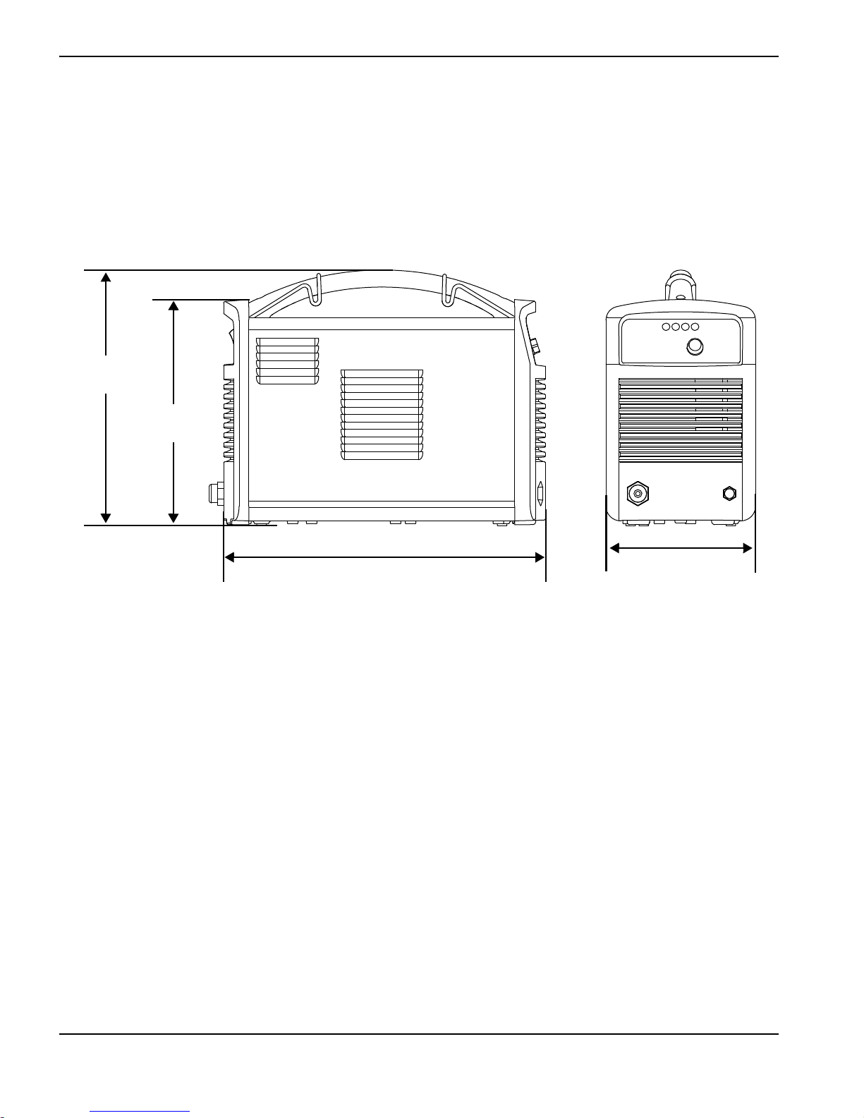
420 mm
(16.5 inches)
195 mm
(7.7 inches)
333 mm
(13.1 inches)
295 mm
(11.6 inches)
CSA units ship with a 120 V / 15 A (NEMA 5-15P) adapter and a 240 V / 20 A (NEMA 6-50P) adapter that connect to
the NEMA twist lock-style 240 V / 20 A (NEMA L6-20P) plug wired to the power supply. CE units ship without a plug on
the power cord. See Power cord considerations on page 27 for more information.
You can order additional consumables and accessories – such as a dust cover and circle cutting guides, for example –
from any Hypertherm distributor. See Parts on page 61 for a list of spare and optional parts.
Power supply dimensions
System weights
The following system weights include the hand torch with 4.6m (15foot) torch lead, a 4.6m (15foot) work lead with
ground clamp, and a 3.0 m (10 foot) power cord:
CSA systems: 13.5 kg (29.8 pounds)
CE systems: 13.4 kg (29.5 pounds)
16 Powermax30 AIR Operator Manual 808840

1 – Specifications
Hypertherm system ratings
Rated open circuit voltage (U0)256VDC
Output characteristic* Drooping
Rated output current (I
Rated output voltage (U
Rated output voltage (U
U
= 200 VAC – 240 VAC
1
Duty cycle at 40°C, U
)15A to 30A
2
) at U1= 120 VAC 83 VDC
2
) at
2
= 120 VAC
1
20% (I2=30A, U2=83V)
83 VDC
(See data plate on power supply’s rear panel for
more information on duty cycle and for
IEC ratings.)
Duty cycle at 40°C, U
= 200 VAC – 240 VAC
1
35% (I2=30A, U2=83V)
(See data plate on power supply’s rear panel for
more information on duty cycle and for
IEC ratings.)
Operating temperature -10°C to 40°C (14°F to 104°F)
Storage temperature -25°C to 55°C (-13°F to 131°F)
Power factor (120 V – 240 V) 0.99 – 0.97
EMC classification CISPR 11
Class A
(CE models only)**
Input voltage (U
output (U
2MAX
)/ Input current (I1) at rated
1
, I
)
2MAX
120 V, 1-phase, 50/60 Hz, 28.7 A
200 V – 240 V, 1-phase, 50/60 Hz, 16.7 A – 15.0 A
†
(See Voltage configurations on page 25 for
more information.)
Gas type Air
* Defined as a plot of output voltage versus output current.
** WARNING: This Class A equipment is not intended for use in residential locations where the electrical power is provided by the
public low.voltage supply system. There may be potential difficulties in ensuring electromagnetic compatibility in those locations,
due to conducted as well as radiated disturbances.
† This product meets the technical requirements of IEC 61000-3-2 and IEC 61000-3-3 and is not subject to conditional
connection.
Powermax30 AIR Operator Manual 808840 17
1 – Specifications
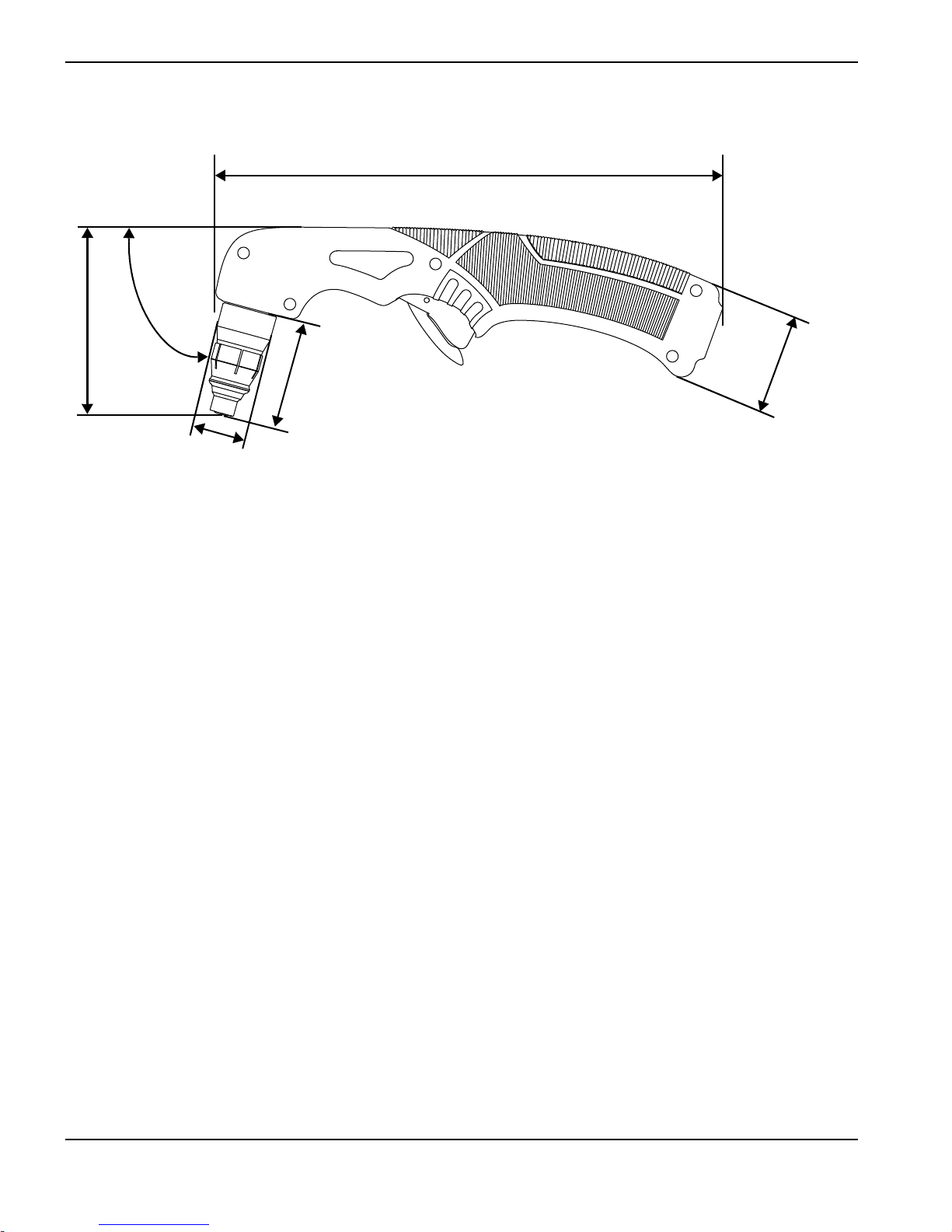
25 mm
(1.0 inch)
51 mm (2.0 inches)
230 mm (9.0 inches)
45 mm
(1.8 inches)
86 mm
(3.4 inches)
75°
Torch dimensions
Torch weight
Air T30 torch with consumables only: 0.3 kg (0.65 pounds)
Air T30 torch with consumables and 4.6 m (15 foot) lead (with strain relief): 1.0 kg (2.25 pounds)
18 Powermax30 AIR Operator Manual 808840

1 – Specifications
Cutting specifications
240 V
Recommended cut capacity* 8 mm (5/16 inch) at a minimum of 500 mm/minute (20 inches/minute)
10 mm (3/8 inch) at a minimum of 250 mm/minute (10 inches/minute)
Severance cut capacity 16 mm (5/8 inch) at a minimum of 125 mm/minute (5 inches/minute)
* When you operate this system at altitudes higher than 2,200 m (7,500 feet) above sea level, you may experience some reduction
in cutting performance due to the adverse effect that altitude has on air compressors.
120 V: When you operate the system at the maximum recommended output of 20 A, the cut capacities are:
3mm (10gauge) at 762mm/minute (30inches/minute)
6 mm (1/4 inch) at 355 mm/minute (14 inches/minute)
10 mm (3/8 inch) at 125 mm/minute (5 inches/minute)
Powermax30 AIR Operator Manual 808840 19

1 – Specifications
Direct current (DC)
Alternating current (AC)
Plasma torch cutting
AC input power connection
The terminal for the external
protective (earth) conductor
I Power is ON
O Power is OFF
An inverter-based power
source
Volt/amp curve, “drooping”
characteristic
Power is ON (LED)
Internal air compressor fault
(LED)
Missing or loose consumables
(LED)
Power supply is overheated
(LED)
f
1
f
2
1~
AC
IEC symbols
The following symbols may appear on the power supply data plate, control labels, switches, and LEDs.
Noise levels
This plasma system may exceed acceptable noise levels as defined by national and local codes. Always wear proper ear
protection when cutting. Any noise measurements taken depend on the specific environment in which the system is used.
Refer to Noise can damage hearing in the Safety and Compliance Manual (80669C) included with your system.
In addition, you can find an Acoustical Noise Data Sheet for your system in the Hypertherm downloads library at
www.hypertherm.com
:
1. Click “Downloads library.”
2. Select a product from the “Product type” menu.
3. Select “Regulatory” from the “Category” menu.
4. Select “Acoustical Noise Data Sheets” from the “Sub Category” menu.
20 Powermax30 AIR Operator Manual 808840
1 – Specifications
s
Symbols and marks
Your product may have one or more of the following markings on or near the data plate. Due to differences and conflicts
in national regulations, not all marks are applied to every version of a product.
S mark
The S mark indicates that the power supply and torch are suitable for operations carried out in environments
with increased hazard of electrical shock according to IEC 60974-1.
CSA mark
Products with a CSA mark meet the United States and Canadian regulations for product safety. The products
were evaluated, tested, and certified by CSA-International. Alternatively, the product may have a mark by one
of the other Nationally Recognized Testing Laboratories (NRTL) accredited in both the United States and
Canada, such as UL or TÜV.
CE mark
The CE marking signifies the manufacturer’s declaration of conformity to applicable European directives and
standards. Only those versions of products with a CE marking located on or near the data plate have been
tested for compliance with the European Low Voltage Directive and the European Electromagnetic
Compatibility (EMC) Directive. EMC filters needed to comply with the European EMC Directive are
incorporated within versions of the product with a CE marking.
Eurasian Customs Union (CU) mark
CE versions of products that include an EAC mark of conformity meet the product safety and EMC
requirements for export to Russia, Belarus, and Kazakhstan.
GOST-TR mark
CE versions of products that include a GOST-TR mark of conformity meet the product safety and EMC
requirements for export to the Russian Federation.
C-Tick mark
CE versions of products with a C-Tick mark comply with the EMC regulations required for sale in Australia
and New Zealand.
CCC mark
The China Compulsory Certification (CCC) mark indicates that the product has been tested and found
compliant with product safety regulations required for sale in China.
UkrSEPRO mark
The CE versions of products that include a UkrSEPRO mark of conformity meet the product safety and EMC
requirements for export to the Ukraine.
Serbian AAA mark
CE versions of products that include a AAA Serbian mark meet the product safety and EMC requirements for
export to Serbia.
Powermax30 AIR Operator Manual 808840 21

1 – Specifications
22 Powermax30 AIR Operator Manual 808840

Section 2
Power Supply Setup
Unpack the plasma system
1. Make sure that you received all items on your order in good condition. Contact your distributor if any parts are
damaged or missing. (See System contents on page 24.)
2. Inspect the system for damage that may have occurred during shipment. If you find evidence of damage, see Claims,
below. All communications regarding this equipment must include the model number and the serial number located
on the rear panel of the power supply.
3. Before you set up and operate this system, read the separate Safety and Compliance Manual (80669C) included
with your system for important safety information.
Claims
Claims for damage during shipment – If your unit was damaged during shipment, file a claim with the carrier. You
can contact Hypertherm for a copy of the bill of lading. If you need additional assistance, call the nearest Hypertherm
office listed in the front of this manual.
Claims for defective or missing merchandise – If any component is missing or defective, contact your
Hypertherm distributor. If you need additional assistance, call the nearest Hypertherm office listed in the front of this
manual.
Powermax30 AIR Operator Manual 808840 23

2 – Power Supply Setup
1
2
3
4
5
6
7
8
11
9
10
1
Operator Manual
2
Quick Setup Card
3
Registration card
4
Safety and Compliance Manual
5
Air T30 torch with lead
6
Consumable kit
7
Ground clamp and work lead
8
CE power cord (no power plug included)
9
CSA power cord with power plug adapters
10
Power supply
11
Carrying strap
System contents
The following illustration shows the components typically included with all system configurations.
The specific components included with the system are subject to change over time.
24 Powermax30 AIR Operator Manual 808840

2 – Power Supply Setup
Position the plasma cutting system
Position the plasma system near an appropriate power receptacle. The system has a 3.0 m (10 foot) power cord.
Allow at least 0.25 m (10 inches) of space around the power supply for proper ventilation.
When positioning the plasma system, be aware that excess moisture from the internal compressor exits through a
hole in the base, underneath the power supply. You may see a small puddle form under the power supply as you
operate the system.
Place the power supply on a stable, level surface before using. The power supply can tip over if set at an angle
greater than 10 degrees.
Do not place the power supply on its side. Doing so can prevent proper air circulation needed to cool internal
components. It can also divert air away from the torch and prevent it from working properly.
Be aware that when you operate this system at altitudes higher than 2,200 m (7,500 feet) above sea level, you may
experience some reduction in cutting performance due to the adverse effect that altitude has on air compressors.
Do not use the system in rain or snow.
WARNING!
Never cut under water or submerge the torch in water.
Prepare the electrical power
The system’s maximum output voltage varies based on the input voltage and the circuit’s amperage.
Additional factors must be considered when you are operating the system at an input power of 120 V, as tripped circuit
breakers can result under some conditions. For more information, see System operation guidelines on page 47 and Basic
troubleshooting on page 56.
Voltage configurations
The system automatically adjusts for proper operation at the current input voltage without requiring you to perform any
switching or rewiring. However, you must make sure that an appropriate set of consumables is properly installed in the
torch and the amperage adjustment knob is set to an appropriate output current. For more information, see
Step 1 – Install the consumables on page 41 and Step 3 – Adjust the output current on page 43.
The following tables show the maximum rated output for typical combinations of input voltage and amperage. The output
setting you need to use depends on the thickness of the metal and is limited by the input power to your system.
Hypertherm does not recommend operating this system on a 120 V / 15 A circuit.
The Hypertherm rated output is:
15 A – 30 A maximum output current
83 VDC maximum rated output voltage
2.5 kW cutting power
Powermax30 AIR Operator Manual 808840 25

2 – Power Supply Setup
Determine the plasma system’s cutting power in watts by multiplying its maximum output amperage by its maximum rated
output voltage:
30 A × 83 VDC = 2,490 W (or 2.5 kW).
CAUTION!
A circuit capable of 120V/20A or 240V/20A is required for proper operation. Protect the circuit
with appropriately sized slow-blow (time-delay) fuses or circuit breakers.
Table1 – 120V/20A
Input voltage 120 V
Input current at rated output (19A×83V=1.6kW) 19.2A
Input current at arc stretch 37.5 A
Voltage tolerance +10% / -10%
Table2 – 120V/30A
Input voltage 120 V
Input current at rated output (30 A × 83 V = 2.5 kW) 28.7 A
Input current at arc stretch 37.5 A
Voltage tolerance +10% / -10%
Table3 – 200V – 240V/16A
Input voltage 200 V – 240 V
Input current at rated output (28A×83V=2.3kW) 15.8A–13.4A
Input current at arc stretch 37.5 A
Voltage tolerance +10% / -10%
Table4 – 200V – 240V/20A
Input voltage 200 V – 240 V
Input current at rated output (30 A × 83 V = 2.5 kW) 16.7 A – 15.0 A
Input current at arc stretch 37.5 A
Voltage tolerance +10% / -10%
26 Powermax30 AIR Operator Manual 808840

2 – Power Supply Setup
Requirements for grounding
Properly ground the system as follows to ensure personal safety and proper operation, and to reduce electromagnetic
interference (EMI):
The system must be grounded through the power cord according to national and local electrical codes.
Single-phase service must be of the three-wire type with a green (CSA) or green/yellow (CE) wire for the protective
earth ground and must comply with national and local requirements. Do not use a two-wire service.
Refer to the Safety and Compliance Manual (80669C) for more information.
Power cord considerations
This system ships with a CSA or CE power cord configuration.
CSA power cords and plugs
CSA configurations include the following plug and adapters.
The power cord is equipped with a NEMA twist
lock-style plug (NEMA L6-20P) appropriate for use on
a 240 V / 20 A circuit with a NEMA twist lock-style
outlet.
To operate the system on a lower amperage circuit,
attach the female end of the 120 V / 15 A
(NEMA 5-15P) plug adapter to the power supply’s
NEMA twist lock-style plug.
Do not set the amperage adjustment knob above
20 A, or you may trip the circuit breaker. See
Step 3 – Adjust the output current on page 43.
To operate the system on a 240 V / 20 A circuit, attach
the female end of the 240 V / 20 A (NEMA 6-50P)
plug to the power supply’s NEMA twist lock-style plug.
Powermax30 AIR Operator Manual 808840 27

2 – Power Supply Setup
1
2
3
4
5
6
1
Cord grip
2
Outer shell
3
To line 1 terminal (brown)
4
230 V (CE) plug
5
To line 2 terminal (blue)
6
To ground terminal (green/yellow)
CE power cords
CE configurations ship without a plug on the power cord. To operate at 230 V (CE), obtain the correct plug for your unit
and location and have it installed by a licensed electrician.
Install a plug on the power cord
1. Strip back the cord insulation to separate wires 3, 5, and 6.
2. Remove each wire’s insulation to allow good contact with the plug terminals.
3. Make the connections.
4. Reinstall the outer shell and cord grip, and tighten the cord grip’s screws until snug. Do not overtighten.
28 Powermax30 AIR Operator Manual 808840

2 – Power Supply Setup
1
1
Extension cord recommendations
Use an extension cord of an appropriate wire gauge for the cord length and system voltage. Use a cord that meets
national and local codes.
Input voltage Phase
Recommended cord gauge size Length
120 VAC 1 4 mm
240 VAC 1 2 mm
Extension cords can cause the machine to receive less input voltage than the output of
the circuit. This can limit the operation of your system.
Generator recommendations
Generators used with this system should produce 240 VAC.
Engine drive rating
5.5kW 30A Full
4kW 25A Limited
Adjust the cutting current as needed based on the generator rating, age, and condition.
Engine drive output current
1-phase (CSA/CE)
2
(12 AWG) Up to 16 m (53 feet)
2
(14 AWG) Up to 40.5 m (133 feet)
Performance (arc stretch)
If a fault occurs while using a generator, turn OFF the system and wait approximately
60 seconds before turning it ON again. Turning the power switch quickly to OFF and
ON again (called a “quick reset”) may not clear the fault.
Powermax30 AIR Operator Manual 808840 29

2 – Power Supply Setup
30 Powermax30 AIR Operator Manual 808840

Section 3
1
2
3
4
5
6
1
Handle
2
Deflector
3
Retaining cap
4
Safety catch
5
Trigger (red )
6
Screws (5)
Torch Setup
Introduction
The Powermax30 AIR includes the Air T30 hand torch. This section explains how to set up and operate your torch. To
achieve optimal consumable life and cut quality, follow the instructions in this manual.
Hand torch components
Powermax30 AIR Operator Manual 808840 31

3 – Torch Setup
Consumable life
Consumable life varies based on the following factors:
Thickness of the metal.
Length of the average cut.
Type of cutting (piercing decreases life when compared to edge cutting).
Pierce height (stretching the arc).
Whether you are cutting solid metal or expanded metal. Cutting expanded metal wears out consumables more
quickly. For more information, see Cutting expanded metal on page 43.
Hypertherm does not recommend the use of any other consumables in the Air T30 torch
except for those listed in this section, which are designed specifically for this system. The
use of any other consumables could adversely affect system performance.
Although largely dependent on the factors listed above, as a general rule, the consumables last approximately
1 to 2 hours of actual “arc on” time. See Inspect the consumables on page 55 for information on the signs of wear to
look for in consumables.
If the consumables’ life is shorter than expected or the cut quality is poor, make sure that you are using the correct
consumables and that they are properly installed. (See the following topic, Consumable use.) Under normal conditions,
the nozzle wears out first.
For optimal cutting performance, always replace the nozzle and the electrode together.
See Hand torch operation on page 48 for more information about proper cutting techniques.
32 Powermax30 AIR Operator Manual 808840

3 – Torch Setup
I
O
Consumable use
WARNING!
INSTANT-ON TORCHES
PLASMA ARC CAN CAUSE INJURY AND BURNS
The plasma arc ignites immediately when you pull the torch trigger. Make
sure the power is OFF before changing consumables.
The hand torch ships with a complete set of consumables installed. The consumables are designed for a broad range of
cutting applications.
The amperage output setting you need to use depends on the thickness of the metal you are planning to cut and is limited
by the input power to your system. See Voltage configurations on page 25.
Do not use any other consumables in the Air T30 torch except for those listed in this
section, which are designed specifically for this system. The use of any other consumables
could adversely affect system performance.
Using the cut charts
Use the following cut charts to guide you in selecting the cutting current (amperage) based on the thickness and type of
the metal you need to cut.
The maximum cut speeds listed in the cut charts are the fastest possible speeds to cut metal without regard to cut quality.
Adjust the cutting speed for your application to obtain the desired cut quality.
Powermax30 AIR Operator Manual 808840 33

3 – Torch Setup
54321 6
1
To rc h
2
Electrode
3
Swirl ring
4
Nozzle
5
Retaining cap
6
Deflector
Consumable set
A complete set of consumables includes:
Electrode
Swirl ring
Nozzle
Retaining cap
Deflector
The following consumables are designed specifically for use with the Powermax30 AIR power supply and
Air T30 hand torch. They cannot be used with any other Powermax system or torch.
Hypertherm does not recommend operating this system on a 120 V / 15 A circuit.
34 Powermax30 AIR Operator Manual 808840

Metric
3 – Torch Setup
240V/30A cutting
Material thickness (mm) Material Arc current (A)
1
2 5,145
3 2,545
4 1,450
5 1,155
7* 570
Mild steel 30
9* 400
11* 280
13* 215
16* 125
1
2 3,290
3 1,970
4 1,260
5 980
Stainless steel 30
7* 535
9* 310
11* 215
13* 170
1
2 6,630
3 3,585
4 2,370
5 1,770
Aluminum 30
7* 575
9* 435
11* 245
13* 135
Maximum cut speed
(mm/minute)
10,16 0
10,16 0
10,16 0
†
†
†
* To cut material thicker than 6 mm (1/4 inch) at 240 V, start the torch at the edge of the workpiece.
† Maximum cut speed is limited by the test table’s maximum speed (10,160 mm/minute or 400 inches/minute).
Powermax30 AIR Operator Manual 808840 35

3 – Torch Setup
English
Material thickness
(gauge/inches)
Material Arc current (A)
Maximum cut speed
18 gauge
14 gauge 214
12 gauge 130
10 g au ge 64
1/4 30
Mild steel 30
5/16* 22
3/8* 13
1/2* 9
5/8* 5
18 gauge
14 gauge 135
10 g au ge 56
1/4 24
Stainless steel 30
3/8* 10
1/2* 7
1/32
1/16 306
1/8 111
1/4 38
Aluminum 30
3/8* 13
1/2* 6
(inches/minute)
395
370
†
400
* To cut material thicker than 6 mm (1/4 inch) at 240 V, start the torch at the edge of the workpiece.
† Maximum cut speed is limited by the test table’s maximum speed (10,160 mm/minute or 400 inches/minute).
36 Powermax30 AIR Operator Manual 808840

Metric
3 – Torch Setup
120 V / 20 A cutting
Material thickness (mm) Material Arc current (A)
1
2 2,420
3 1,245
4* 680
6* 400
8* 235
10* 90
1
2 2,140
3 1,270
4* 965
5* 660
7* 150
1
2 3,610
3 1,720
4* 1,030
5* 740
7* 165
Mild steel 20
Stainless steel 20
Aluminum 20
Maximum cut speed
(mm/minute)
6,540
3,295
5,500
* To cut material thicker than 3 mm (10 gauge) at 120 V, start the torch at the edge of the workpiece.
Powermax30 AIR Operator Manual 808840 37

3 – Torch Setup
English
Material thickness
(gauge/inches)
18 gauge
14 gauge 10 0
10 g au ge 30
1/4* 14
3/8* 5
18 gauge
14 gauge 89
12 gauge 54
1/4* 10
1/32
1/16 170
1/8 49
1/4* 14
* To cut material thicker than 3 mm (10 gauge) at 120 V, start the torch at the edge of the workpiece.
Material Arc current (A)
Mild steel 20
Stainless steel 20
Aluminum 20
Maximum cut speed
(inches/minute)
220
120
231
38 Powermax30 AIR Operator Manual 808840

Controls and indicators
O
O
Familiarize yourself with the controls and LED indicators on the system before you begin cutting.
Rear controls
Section 4
Operation
ON (I) / OFF (O) power switch
Activates the system and its control circuits.
Powermax30 AIR Operator Manual 808840 39

4 – Operation
AC
Front panel controls and indicator LED symbols
Power ON LED (green) – When illuminated, this LED indicates that the power switch has been set to ON (I)
and that the safety interlocks are satisfied.
Internal compressor LED (yellow) – When illuminated, this LED indicates a possible issue with the internal
air compressor.
Torch cap LED (yellow) – When illuminated, this LED indicates that the consumables are loose, improperly
installed, or missing.
Temperature LED (yellow) – When illuminated, this LED indicates that the system’s temperature is outside
the acceptable operating range.
Some fault conditions cause multiple LEDs to illuminate or blink at the same time. For
information on what these fault conditions are and how to clear them, see Basic
troubleshooting on page 56.
Amperage adjustment knob – Use this knob to set the output current
between 15 A and 30 A.
40 Powermax30 AIR Operator Manual 808840

Operate the plasma system
I
O
Tighten only to finger tight.
1
2
3
4
5
1
234
5
The following topics explain how to begin cutting with the plasma system.
Step 1 – Install the consumables
WARNING!
INSTANT-ON TORCHES
PLASMA ARC CAN CAUSE INJURY AND BURNS
The plasma arc ignites immediately when you pull the torch trigger. Make
sure the power is OFF (O) before changing consumables.
Before operating the plasma system
and hand torch, first make sure:
1. The power switch on the power
supply is in the OFF (O) position.
4–Operation
2. A complete set of consumables is
installed on the hand torch
as shown:
Electrode
Swirl ring
Nozzle
Retaining cap
Deflector*
* Install the deflector by snapping it
securely into place on the retaining cap.
Do not apply grease or
other lubricants to the
O-rings on the electrode
and swirl ring.
These consumables are designed specifically for the Powermax30 AIR power supply and
Air T30 hand torch. They cannot be used with any other Powermax system or torch.
Powermax30 AIR Operator Manual 808840 41

4 – Operation
Step 2 – Connect the electrical power
Plug in the power cord.
See also
For information on connecting the proper plug to the power cord, see Power cord considerations on page 27.
To understand what cutting capacity to expect based on input voltage, see Consumable use on page 33.
For information on electrical requirements for this system, see Power Supply Setup on page 23.
42 Powermax30 AIR Operator Manual 808840

4–Operation
Blue shading
Step 3 – Adjust the output current
The power ON LED illuminates when the system is powered ON and ready to operate.
If any of the other LEDs illuminate or blink, do not try to cut – a fault has occurred. Refer to Basic troubleshooting on
page 56 for a list of troubleshooting steps to follow.
When the system is ready to cut, turn the amperage knob to the desired output current based on the input voltage and
circuit size.
Operating the system on a 120 V / 20 A circuit
Set the amperage below 20 A, as indicated by the
blue shading around the knob (the thick inner ring).
Make sure nothing else is drawing power from the
circuit.
Hypertherm does not recommend operating this
system on a 120 V / 15 A circuit.
Operating the system on a 240 V / 20 A circuit
Set the amperage between 15 – 30 A.
Decrease output current for lower-rated power
plugs
If you are operating the system using a lower-rated power
plug or service, turn down the output current to avoid
tripping the circuit breaker.
For example, to operate the system on a 230 V / 16 A
circuit, set the amperage below 28 A.
See Voltage configurations on page 25 for more information.
Cutting expanded metal
Use the consumables that come with the torch to cut expanded metal. (Expanded metal has a slotted or mesh pattern.)
The system does not require a dedicated mode for cutting expanded metal.
Cutting expanded metal wears out consumables more quickly because it requires a continuous pilot arc. A pilot arc
occurs when the torch is fired but the plasma arc is not in contact with the workpiece.
For best results, operate on a higher rated circuit (240 V / 20 A).
Powermax30 AIR Operator Manual 808840 43

4 – Operation
O
O
Step 4 – Attach the ground clamp
Attach the ground clamp to the workpiece.
Make sure the ground clamp and the workpiece make good metal-to-metal contact.
Attach the ground clamp as close as possible to the area being cut to reduce exposure to electric and magnetic
fields (EMF) and to achieve the best possible cut quality.
Do not attach the ground clamp to the portion of the workpiece that you are cutting away.
Step 5 – Power ON the system
Set the ON/OFF switch to the ON (I) position.
44 Powermax30 AIR Operator Manual 808840

4–Operation
Step 6 – Check the indicator LEDs
Make sure the green power ON LED on the front
of the power supply is illuminated and that none of
the other LEDs are illuminated or blinking.
If the temperature, torch cap sensor, or internal
compressor LEDs illuminate or blink, or if the
power ON LED blinks, this indicates a fault.
Correct the fault condition before continuing. See
Basic troubleshooting on page 56 for more
information.
Step 7 – Make sure the system is ready, and start cutting
When the power ON LED illuminates, none of the other LEDs illuminate or blink, and the amperage knob is set, the
system is ready for use.
What to expect during and after cutting
Postflow
After you complete a cut and release the torch trigger, air continues to flow from the torch in order to cool the
consumables. This is referred to as postflow.
The length of postflow depends on how long the torch fired a sustained arc:
Length of time arc was sustained Length of postflow
0–5seconds 5seconds
> 5 – 21 seconds 10 seconds
> 21 – 135 seconds 15 seconds
> 135 seconds 20 seconds
Internal compressor and fan activity
The internal compressor runs while you are cutting, and it continues to run during postflow.
The fan inside the power supply runs for 7 minutes after postflow. It also runs intermittently during cutting.
Water under the power supply
When cutting, you may see a small puddle form underneath the power supply because the system automatically
purges excess moisture from the internal compressor. It expels this water through a hole in the bottom of the power
supply.
Powermax30 AIR Operator Manual 808840 45

4 – Operation
Understand duty-cycle limitations
The duty cycle is the percentage of time out of 10 minutes that a plasma arc can remain on when operating at an ambient
temperature of 40° C (104° F).
35% duty cycle at 240 V / 30 A: With input power of 240 V and the output current set to 30 A, the arc can remain
on for 3.5 minutes out of 10 minutes without causing the unit to overheat.
20% duty cycle at 120 V / 30 A*: With input power of 120 V and the output current set to 30 A, the arc can
remain on for 2.0 minutes out of 10 minutes without causing the unit to overheat.
* Although the duty cycle is rated for 30 A output, the recommended output current for 120 V circuits is 20 A or less. Operating the
system at 30 A on 120 V input can result in frequent tripped circuit breakers.
When you exceed the duty cycle and the system overheats, one of the following conditions occurs:
The temperature LED illuminates, the arc shuts off, and the cooling fan continues to run. To resume cutting, wait for
the temperature LED to extinguish.
The internal compressor LED and the temperature LED both illuminate. Allow the power supply to cool for 4 minutes
before using it again. If the problem persists, see Internal compressor LED faults on page 58 for more
troubleshooting tips.
When either condition occurs, leave the system on to allow the fan to cool the power
supply. The fan runs for 7 minutes after postflow.
Stretching the arc for prolonged periods while cutting can reduce the duty cycle. Stretching the arc requires the power
supply to generate a higher voltage output, which can cause it to run hotter and overheat more quickly.
46 Powermax30 AIR Operator Manual 808840

4–Operation
System operation guidelines
To achieve the highest level of performance:
Operate the system at an input power of 240 VAC whenever possible.
Do not operate the system on a 120 V / 15 A circuit.
Avoid using an extension cord whenever possible.
If you must use an extension cord, use a heavy conductor cord of the shortest possible
length. See Extension cord recommendations on page 29.
If you are operating your system on a 120 V / 20 A circuit, do not set the amperage higher than 20 A. See Voltage
configurations on page 25.
For best results when operating your system on a 120 V / 20 A circuit:
Do not connect anything else that will draw power from the same circuit.
Be aware that extension cords can reduce the voltage to the machine from what is output by the circuit. This
reduction in power can impair cutting performance and increase the probability of tripping the circuit breaker.
Cutting a thicker workpiece requires a higher amperage setting. It is preferable to operate on a higher rated circuit
(240 V / 30 A) when cutting thicker metal. See Voltage configurations on page 25.
Additional techniques to reduce the frequency of tripped circuit breakers include:
Turn down the amperage adjustment knob.
Avoid stretching the arc. Instead, drag the torch on the workpiece as explained in Edge start on a workpiece on
page 50.
When you operate the system at altitudes higher than 2,200 m (7,500 feet) above sea level, you may experience
some reduction in cutting performance due to the adverse effect that altitude has on the internal air compressor.
Powermax30 AIR Operator Manual 808840 47

4 – Operation
1
2
3
Hand torch operation
WARNING!
INSTANT-ON TORCHES
PLASMA ARC CAN CAUSE INJURY AND BURNS
Plasma arc ignites immediately when you pull the torch trigger. The plasma arc cuts quickly through
gloves and skin.
Keep hands, clothes, and objects away from the torch tip.
Do not hold the workpiece, and keep your hands clear of the cutting path.
Never point the torch toward yourself or others.
WARNING!
SPARKS AND HOT METAL
CAN INJURE EYES AND BURN SKIN
Always wear proper protective equipment including gloves and eye protection, and point the torch
away from yourself and others. Sparks and hot molten metal spray out from the nozzle.
Safety catch operation
The torch is equipped with a safety catch to prevent accidental firings. When you are ready to cut with the torch, flip the
safety catch forward (toward the torch head) and pull the red torch trigger.
48 Powermax30 AIR Operator Manual 808840

4–Operation
Hand torch cutting guidelines
Drag the torch tip lightly on the workpiece to maintain a steady cut speed.
With drag-cutting, it is normal to experience the torch sticking slightly to the workpiece.
While cutting, make sure that sparks exit from the bottom of the workpiece. The sparks should lag slightly behind the
torch as you cut (15°–30° angle from vertical).
If sparks spray up, you are not cutting all the way through the workpiece. Move the torch more slowly, or, if possible,
increase the output current.
Hold the torch nozzle perpendicular to the workpiece so that the nozzle is at a 90° angle to the cutting surface, and
watch the arc as it cuts along the line.
Pulling the torch toward you along the cut is easier than pushing it or moving from side-to-side.
For straight-line cuts, use a straight edge as a guide. To cut circles, use a template or a radius cutter attachment (a
circle cutting guide). See Accessory parts on page 65 for the Hypertherm plasma cutting guide part numbers for
cutting circles and making bevel cuts.
If you fire the torch unnecessarily, you shorten the life of the nozzle and electrode.
Recommendations for cutting at 120 V
Do not operate the system on a 15 A circuit.
Do not use an extension cord.
Make sure nothing else is drawing power from the circuit.
Turn down the current adjustment knob to avoid tripping the breaker.
Powermax30 AIR Operator Manual 808840 49

4 – Operation
Edge start on a workpiece
When cutting material up to 10 mm (3/8 inch) thick, start the torch at the edge of the workpiece to prolong consumable
life.
1. With the ground clamp attached to the workpiece,
hold the torch perpendicular (90°) to the workpiece
and on the edge.
2. Pull the torch trigger to start the arc. You may need
to pause at the edge until the arc has cut completely
through the workpiece.
3. Drag the torch lightly across the workpiece to
proceed with the cut. Maintain a steady, even pace.
50 Powermax30 AIR Operator Manual 808840

4–Operation
30° – 45° for rolling pierce
Pierce a workpiece
When cutting material up to 6 mm (1/4 inch) thick, use piercing to cut an interior feature. Piercing shortens the life of the
deflector and the nozzle.
The type of pierce to perform depends on the thickness of the metal:
Straight pierce – For cutting mild or stainless steel that is thinner than 3 mm (10 gauge).
Rolling pierce – For cutting mild or stainless steel that is 3 mm (10 gauge) or thicker.
1. Attach the ground clamp to the workpiece.
2. Straight pierce: Hold the torch perpendicular (90°)
to the workpiece with the torch tip just above the
workpiece.
Rolling pierce: Hold the torch at an approximate
30° – 45° angle to the workpiece with the torch tip
within 1.5 mm (1/16 inch) of it before firing the
torch.
3. Straight pierce: Pull the torch trigger to start the
arc.
Rolling pierce: Pull the torch trigger to start the arc
while still at an angle to the workpiece, then rotate
the torch to the perpendicular (90°) position.
4. Hold the torch in place while continuing to pull the
trigger. When sparks exit from the bottom of the
workpiece, the arc has pierced the metal.
5. When the pierce is complete, drag the torch lightly
along the workpiece to proceed with the cut.
Powermax30 AIR Operator Manual 808840 51

4 – Operation
Common hand-cutting faults
For more information on faults, see Basic troubleshooting on page 56.
The torch sputters and hisses, but does not produce an arc. The cause can be:
Overtightened consumables
The torch does not cut completely through the workpiece. The causes can be:
Cut speed is too fast
Worn consumables
Metal being cut is too thick for the selected amperage
Installation of the wrong consumables
Poor electrical contact between the ground clamp and the workpiece
Cut quality is poor. The causes can be:
Metal being cut is too thick for the selected amperage
Installation of the wrong consumables
Cut speed is too fast or too slow
Worn or damaged consumables
The arc sputters and consumables life is shorter than expected. The causes can be:
Incorrect installation of the consumables
Installation of the wrong consumables
Moisture in the consumables or in the air supply within the system
Minimizing dross
Dross is the molten metal that solidifies on the workpiece. Some amount of dross is always present when cutting with air
plasma. However, you can control the amount and type of dross by adjusting your system correctly for your application.
Low-speed dross forms when the torch’s cutting speed is too slow and the arc shoots ahead. It forms as a heavy, bubbly
deposit at the bottom of the cut and is usually easy to remove. Increase your speed to reduce this type of dross.
High-speed dross forms when the cutting speed is too fast and the arc lags behind. It forms as a thin, linear bead of solid
metal attached very close to the cut. It forms to the bottom of the cut and is often more difficult to remove. Decrease your
speed to reduce this type of dross.
Dross is more likely to form on warm or hot metal than on cool metal. For example, the
first cut in a series of cuts is likely to produce the least dross. As the workpiece heats up,
more dross may form on subsequent cuts.
Worn or damaged consumables may produce intermittent dross.
52 Powermax30 AIR Operator Manual 808840

Perform routine maintenance
Disconnect electrical power before performing any maintenance that
involves removing the cover from the power supply or the consumables from
the torch.
All work requiring removal of the power supply cover must be performed by
a qualified technician.
See the Safety and Compliance Manual (80669C) for more safety
precautions.
Section 5
Maintenance and Troubleshooting
WARNING!
ELECTRIC SHOCK CAN KILL
Powermax30 AIR Operator Manual 808840 53

5 – Maintenance and Troubleshooting
Every use:
Check the indicator lights and correct any fault
conditions.
Every 3 months:
Replace any damaged labels. Inspect the trigger for damage. Inspect the torch body
Inspect the power cord and plug.
Replace if damaged.
Inspect the consumables for proper installation and
wear.
for cracks and exposed wires. Replace any damaged
parts.
Inspect the torch lead. Replace if damaged.
54 Powermax30 AIR Operator Manual 808840

Inspect the consumables
Good
Worn
O-ring
Maximum 1.6 mm
(1/16 inch)
O-ring
Part Inspect Action
5 – Maintenance and Troubleshooting
Deflector
Nozzle
Electrode
The center hole for roundness.
The rounded edges of the center hole
for damage or noticeable wear.
The gap between the nozzle and the
deflector for accumulated debris.
Replace the deflector if the hole is no
longer round or if it is worn or
damaged.
Remove the deflector and clean any
material away.
The center hole for roundness. Replace if the center hole is not round.
Replace the nozzle and the electrode
together.
The center surface for wear and verify
the pit depth.
Replace if the surface is severely worn
or the pit depth is greater than 1.6 mm
(1/16 inch) deep. Replace the nozzle
and the electrode together.
Do not apply grease or other lubricants
to the O-ring on the electrode.
Swirl ring
Torch O-ring
The internal surface for damage or
wear and the gas holes for blockages.
Replace if the surface is damaged or
worn or any of the gas holes are
blocked.
Do not apply grease or other lubricants
to the O-ring on the swirl ring.
The length of the swirl ring. If the length of the swirl ring is less than
21 mm (0.83 inches), replace it.
The surface for damage, wear, or a lack
of lubrication.
If the torch O-ring is dry, apply a thin
film of silicone lubricant on the O-ring
and the threads. The O-ring should
look shiny, but there should not be any
excess or built-up lubricant.
If the O-ring is cracked or worn,
replace it.
Powermax30 AIR Operator Manual 808840 55

5 – Maintenance and Troubleshooting
AC
AC
O
AC
Basic troubleshooting
The following sections provide an overview of the most common problems that may arise when using this system and
explains how to solve them.
If you are unable to fix the problem by following this basic troubleshooting guide or if you need further assistance:
1. Call your Hypertherm distributor or authorized Hypertherm repair facility.
2. Call the nearest Hypertherm office listed in the front of this manual.
Power LED faults
The ON/OFF power switch is set to ON (I),
but the power ON LED does not illuminate.
Make sure the power cord is plugged into the receptacle.
Make sure the power is on at the main power panel or at the disconnect-power switch box.
Make sure the line voltage is not too low (more than 15% below the rated voltage).
The power ON LED blinks.
Have an electrical technician check the incoming power. The input line voltage is either too high or
too low (a variance greater than ±15% of the rated voltage). See Hypertherm system ratings on
page 17 and Prepare the electrical power on page 25.
All four LEDs blink when the system is powered ON.
A qualified service technician must service the system. Contact your distributor or use the
information in the front of this manual to contact Hypertherm Technical Service.
56 Powermax30 AIR Operator Manual 808840

5 – Maintenance and Troubleshooting
Temperature LED faults
The temperature LED illuminates while the machine is powered ON.
The system overheated. Leave the system on to allow the fan to cool the power supply.
If the system’s internal temperature approaches -30°C (-22°F), the temperature LED may
illuminate. Move the system to a warmer location.
The temperature LED blinks while the machine is powered ON.
Leave the system on to allow the fan to cool the power supply. The temperature LED blinks when
the system continuously draws too much input current for too long. Try the following to prevent this
condition:
Turn down the cutting current. See Step 3 – Adjust the output current on page 43.
Operate the system on a 240 VAC input circuit whenever possible.
Avoid stretching the arc. Drag the torch on the workpiece. See Edge start on a
workpiece on page 50.
Operate the system without using an extension cord. If you must use an extension
cord, use a heavy conductor cord of the shortest possible length. See Extension cord
recommendations on page 29.
Make sure nothing else is drawing power on the same circuit.
Powermax30 AIR Operator Manual 808840 57

5 – Maintenance and Troubleshooting
Internal compressor LED faults
The internal compressor LED and the temperature LED illuminate while
the machine is powered ON.
The internal compressor may have overheated. Allow the power supply to cool for 4 minutes before
using it again. (See Understand duty-cycle limitations on page 46.)
When the internal compressor overheats, the compressor and temperature LEDs remain
illuminated for 4 minutes.
The system does not prevent you from firing the torch before the 4 minutes
elapses. However, if you begin cutting before the compressor has time to
fully cool down, the same fault is likely to occur again.
Place the power supply right-side up on a level surface. Laying the power supply on its side can
prevent proper air circulation needed to cool internal components. It can also cause the air filter to
divert air away from the torch.
Inspect and replace the consumables if they are worn or damaged. Always replace the nozzle and
electrode together. See Inspect the consumables on page 55.
Was the system stored in temperatures below freezing? If so, ice might have formed inside the
power supply. Move the power supply to a warmer location to allow the ice to melt.
If none of these troubleshooting steps resolves the issue, a qualified service technician must
service the system. Contact your distributor or use the information in the front of this manual to
contact Hypertherm Technical Service.
The internal compressor LED and the temperature LED blink alternately
when the machine is powered ON.
Release the trigger and restart the power supply. The system automatically disables itself when the
power supply is turned on while the torch trigger is pulled.
58 Powermax30 AIR Operator Manual 808840

5 – Maintenance and Troubleshooting
AC
Torch LED faults
The torch cap LED illuminates or blinks while the machine is
powered ON.
Inspect the torch lead. If it is twisted or kinked, straighten it out and try to fire the torch again.
Turn OF F ( O) the power supply. Make sure the consumables are properly installed and tightened.
See Step 1 – Install the consumables on page 41.
If the consumables became loose or were removed while the power supply was ON, turn OFF (O)
the power supply, correct the problem, and then turn ON (I) the power supply to clear the fault.
If the consumables appear to be installed correctly, the torch may be damaged. Contact your
Hypertherm distributor or authorized repair facility.
The internal compressor, temperature, and power ON
LEDs blink, and the torch cap LED illuminates.
Install new consumables in the torch (they may be corroded or approaching end of life).
If you continue to see this error, contact your Hypertherm distributor or authorized repair facility.
Powermax30 AIR Operator Manual 808840 59

5 – Maintenance and Troubleshooting
Common cutting issues
Problem Solution
The circuit breaker trips
while you are cutting.
The cut quality is poor. • Make sure the torch is being used correctly. See Hand torch operation on
• Turn down the cutting current. See Step 3 – Adjust the output current on
page 43.
• Operate the system on a 240 VAC input circuit whenever possible.
• Avoid stretching the arc. Drag the torch on the workpiece. See Edge start
on a workpiece on page 50.
• Operate the system without using an extension cord. If you must use an
extension cord, use a heavy conductor cord of the shortest possible
length. See Extension cord recommendations on page 29.
• Make sure nothing else is drawing power on the same circuit.
page 48.
• Make sure the correct consumables are installed. See Consumable use
on page 33.
• Inspect the consumables and replace as necessary. See Inspect the
consumables on page 55.
• Loosen the consumables about 1/8th of a turn and try again.
• Make sure the work lead connection is secure and there is no damage to
the work lead.
• Operate the system without using an extension cord. If you must use an
extension cord, use a heavy conductor cord of the shortest possible
length. See Extension cord recommendations on page 29.
The torch does not cut
completely through the
workpiece.
The arc does not transfer
to the workpiece.
The arc blows out but
re-ignites when the torch
trigger is pulled again, or
the arc sputters and
hisses.
• Make sure the torch is being used correctly. See Hand torch operation on
page 48.
• Inspect the consumables and replace as necessary. See Inspect the
consumables on page 55.
• Clean the area where the ground clamp contacts the workpiece to ensure
a good metal-to-metal contact.
• Inspect the ground clamp for damage and repair it if necessary.
• Move the torch closer to the workpiece and fire the torch again. See Hand
torch operation on page 48.
• First, inspect the consumables for signs of moisture. If moisture is present,
fire the torch approximately 5 times in succession.
• If the problem persists, inspect and replace the consumable parts if they
are worn or damaged. See Inspect the consumables on page 55.
60 Powermax30 AIR Operator Manual 808840

Section 6
Parts
Use the part and kit numbers in this section to order consumables, accessories, and external replacement parts for your
power supply and hand torch.
For instructions on installing the consumables in the hand torch, see Step 1 – Install the
consumables on page 41.
This system contains no customer serviceable parts inside the power supply or inside the hand torch. For assistance with
repairing or replacing internal components:
1. Call your Hypertherm distributor or authorized Hypertherm repair facility.
2. Call the nearest Hypertherm office listed in the front of this manual.
Powermax30 AIR Operator Manual 808840 61

6 – Parts
1
2
3
Power supply parts
Exterior, front
Item Kit number Description
1 228267 Kit: Power supply handle (includes screws and shoulder strap clips)
2 428226 Kit: Current adjustment knob
3 228561 Kit: Ground clamp
62 Powermax30 AIR Operator Manual 808840

Exterior, rear
1
2
NEMA 6-50P
NEMA 5-15P
NEMA L6-20P
6 – Parts
Item Kit number Description
1 229133 CSA power cord extension: 240 V / 20 A plug adapter
2 229132 CSA power cord extension: 120 V / 15 A plug adapter
428392 Kit: Replacement bumpers (rubber “feet”) for bottom of power supply (4)
(not shown)
Powermax30 AIR Operator Manual 808840 63

6 – Parts
420133420132 420134 42013 5
Electrode Swirl ring Nozzle Retaining cap
428179
Torch O-ring Deflector
420399
428350
Hand torch consumables
To order consumables for your Air T30 torch, use the following part numbers.
You can order individual packages of nozzles and electrodes, or you can order them combined as a kit:
Use 420134 to order a package of 5 nozzles.
Use 420132 to order a package of 5 electrodes.
Use 428350 to order a kit of 2 nozzles and 2 electrodes.
These consumables are designed specifically for use with the Powermax30 AIR power
supply and Air T30 hand torch. They cannot be used with any other Powermax system or
torch.
Individual consumables
64 Powermax30 AIR Operator Manual 808840
Electrode + nozzle kit

Accessory parts
Part number Description
127102 Basic plasma (circle) cutting guide
027668 Deluxe plasma (circle) cutting guide
127144 Dust cover
024548 Leather torch lead cover, brown, 7.6 m (25 feet)
024877 Leather torch lead cover, black with Hypertherm logo, 7.6 m (25 feet)
127217 Shoulder strap
127169 Leather cutting gloves
127416 Protective glasses, shade 5 lens
6 – Parts
Powermax30 AIR Operator Manual 808840 65

6 – Parts
210347 Rev. A
420135 420134 420133 420132420399
428350
Power supply labels
Kit number Description
428408 Kit: Powermax30 AIR labels, CSA
428410 Kit: Powermax30 AIR labels, CSA, Built in America
428409 Kit: Powermax30 AIR labels, CE
The label kits include:
Consumables label
Appropriate warning labels
Front and side decals
The following illustrations show the consumables label and warning labels.
Consumables label
The consumables label is affixed to the power supply’s rear panel. It shows the correct consumables to use with this
system and torch and how to install them.
66 Powermax30 AIR Operator Manual 808840

6 – Parts
Read and follow these instructions, employer safety
practices, and material safety data sheets. Refer to
ANS Z49.1, “Safety in Welding, Cutting and Allied
Processes” from American Welding Society
(http://www.aws.org) and OSHA Safety and Health
Standards, 29 CFR 1910 (http://www.osha.gov).
WARNING
1. Cutting sparks can cause explosion or fire.
1.1 Do not cut near flammables.
1.2 Have a fire extinguisher nearby and ready to use.
1.3 Do not use a drum or other closed container as a
cutting table.
2. Plasma arc can injure and burn; point the
nozzle away from yourself. Arc starts
instantly when triggered.
2.1 Turn off power before disassembling torch.
2.2 Do not grip the workpiece near the cutting path.
2.3 Wear complete body protection.
3. Hazardous voltage. Risk of electric shock or
burn.
3.1 Wear insulating gloves. Replace gloves when wet or
damaged.
3.2 Protect from shock by insulating yourself from work and
ground.
3.3 Disconnect power before servicing. Do not touch live parts.
4. Plasma fumes can be hazardous.
4.1 Do not inhale fumes.
4.2 Use forced ventilation or local exhaust to remove the
fumes.
4.3 Do not operate in closed spaces. Remove fumes with
ventilation.
6. Become trained. Only qualified personnel should
operate this equipment. Use torches specified in the
manual. Keep non-qualified personnel and children away.
5. Arc rays can burn eyes and injure skin.
5.1 Wear correct and appropriate protective equipment to
protect head, eyes, ears, hands, and body. Button shirt
collar. Protect ears from noise. Use welding helmet with
the correct shade of filter.
7. Do not remove, destroy, or cover this label.
Replace if it is missing, damaged, or worn.
Plasma cutting can be injurious to operator and persons
in the work area. Consult manual before operating. Failure
to follow all these safety instructions can result in death.
(PN 110673 Rev D)
AVERTISSEMENT
Le coupage plasma peut être préjudiciable pour l’opérateur
et les personnes qui se trouvent sur les lieux de travail.
Consulter le manuel avant de faire fonctionner. Le non respect
des ces instructions de sécurité peut entraîner la mort.
1. Les étincelles de coupage peuvent provoquer
une explosion ou un incendie.
1.1 Ne pas couper près des matières inflammables.
1.2 Un extincteur doit être à proximité et prêt à être utilisé.
1.3 Ne pas utiliser un fût ou un autre contenant fermé comme
table de coupage.
2. L’arc plasma peut blesser et brûler; éloigner
la buse de soi. Il s’allume instantanément
quand on l’amorce.
2.1 Couper l’alimentation avant de démonter la torche.
2.2 Ne pas saisir la pièce à couper de la trajectoire de coupage.
2.3 Se protéger entièrement le corps.
3. Tension dangereuse. Risque de choc électrique
ou de brûlure.
3.1 Porter des gants isolants. Remplacer les gants quand ils sont
humides ou endommagés.
3.2 Se protéger contre les chocs en s’isolant de la pièce et de
la terre.
3.3 Couper l’alimentation avant l’entretien. Ne pas toucher
les pièces sous tension.
4. Les fumées plasma peuvent être
dangereuses.
4.1 Ne pas inhaler les fumées.
4.2 Utiliser une ventilation forcée ou un extracteur local pour
dissiper les fumées.
4.3 Ne pas couper dans des espaces clos. Chasser les fumées
par ventilation.
5. Les rayons d’arc peuvent brûler les yeux et
blesser la peau.
5.1 Porter un bon équipement de protection pour se protéger
la tête, les yeux, les oreilles, les mains et le corps. Boutonner
le col de la chemise. Protéger les oreilles contre le bruit. Utiliser
un masque de soudeur avec un filtre de nuance appropriée.
6. Suivre une formation. Seul le personnel qualifié a
le droit de faire fonctionner cet équipement. Utiliser
exclusivement les torches indiquées dans le manual. Le
personnel non qualifié et les enfants doivent se tenir à l’écart.
7. Ne pas enlever, détruire ni couvrir cette étiquette.
La remplacer si elle est absente, endommagée ou usée.
(
PN 110673 Rev D)
CSA warning label
This warning label is affixed to some power supplies. It is important that the operator and maintenance technician
understand the intent of these warning symbols as described.
Powermax30 AIR Operator Manual 808840 67

6 – Parts
CE warning label
This warning label is affixed to some power supplies. It is important that the
operator and maintenance technician understand the intent of these
warning symbols as described. The numbered text corresponds to the
numbered boxes on the label.
1. Cutting sparks can cause explosion
or fire.
1.1 Do not cut near flammables.
1.2 Have a fire extinguisher nearby and
ready to use.
1.3 Do not use a drum or other closed
container as a cutting table.
2. Plasma arc can injure and burn; point
the nozzle away from yourself. Arc
starts instantly when triggered.
2.1 Turn off power before disassembling
torch.
2.2 Do not grip the workpiece near the
cutting path.
2.3 Wear complete body protection.
3. Hazardous voltage. Risk of electric
shock or burn.
3.1 Wear insulating gloves. Replace
gloves when wet or damaged.
3.2 Protect from shock by insulating
yourself from work and ground.
3.3 Disconnect power before servicing.
Do not touch live parts.
4. Plasma fumes can be hazardous.
4.1 Do not inhale fumes.
4.2 Use forced ventilation or local exhaust
to remove the fumes.
4.3 Do not operate in closed spaces.
Remove fumes with ventilation.
5. Arc rays can burn eyes and injure
skin.
5.1 Wear correct and appropriate
protective equipment to protect head,
eyes, ears, hands, and body. Button
shirt collar. Protect ears from noise.
Use welding helmet with the correct
shade of filter.
6. Become trained. Only qualified
personnel should operate this
equipment. Use torches specified in
the manual. Keep non-qualified
personnel and children away.
7. Do not remove, destroy, or cover this
label. Replace if it is missing,
damaged, or worn.
68 Powermax30 AIR Operator Manual 808840
 Loading...