

Page 1

Powermax30®XP
Plasma Arc Cutting System
Service Manual
808150 | Revision 1 | English
Page 2

Register your new Hypertherm system
Register your product online at www.hypertherm.com/registration for easier technical
and warranty support. You can also receive updates on new Hypertherm products and a free
gift as a token of our appreciation.
For your records
Serial number:________________________________________________________________
Purchase date: _______________________________________________________________
Distributor: __________________________________________________________________
____________________________________________________________________________
____________________________________________________________________________
Maintenance notes:
____________________________________________________________________________
____________________________________________________________________________
____________________________________________________________________________
____________________________________________________________________________
____________________________________________________________________________
____________________________________________________________________________
Powermax, Duramax, FineCut, and Hypertherm are trademarks of Hypertherm Inc. and may be registered in the United States and
other countries. All other trademarks are the property of their respective holders.
© 2014 Hypertherm Inc.
Page 3

Powermax30 XP
Service Manual
808150
Revision 1
English
March 2014
Hypertherm Inc.
Hanover, NH 03755 USA
Page 4

Hypertherm Inc.
Etna Road, P.O. Box 5010
Hanover, NH 03755 USA
603-643-3441 Tel (Main Office)
603-643-5352 Fax (All Departments)
info@hypertherm.com (Main Office Email)
800-643-9878 Tel (Technical Service)
technical.service@hypertherm.com (Technical Service Email)
800-737-2978 Tel (Customer Service)
customer.service@hypertherm.com (Customer Service Email)
866-643-7711 Tel (Return Materials Authorization)
877-371-2876 Fax (Return Materials Authorization)
return.materials@hypertherm.com (RMA email)
Hypertherm Plasmatechnik GmbH
Technologiepark Hanau
Rodenbacher Chaussee 6
D-63457 Hanau-Wolfgang, Deutschland
49 6181 58 2100 Tel
49 6181 58 2134 Fax
49 6181 58 2123 (Technical Service)
Hypertherm (S) Pte Ltd.
82 Genting Lane
Media Centre
Annexe Block #A01-01
Singapore 349567, Republic of Singapore
65 6841 2489 Tel
65 6841 2490 Fax
65 6841 2489 (Technical Service)
Hypertherm (Shanghai) Trading Co., Ltd.
Unit 301, South Building
495 ShangZhong Road
Shanghai, 200231
PR China
86-21-60740003 Tel
86-21-60740393 Fax
Hypertherm Europe B.V.
Vaartveld 9
4704 SE
Roosendaal, Nederland
31 165 596907 Tel
31 165 596901 Fax
31 165 596908 Tel (Marketing)
31 165 596900 Tel (Technical Service)
00 800 4973 7843 Tel (Technical Service)
Hypertherm Japan Ltd.
Level 9, Edobori Center Building
2-1-1 Edobori, Nishi-ku
Osaka 550-0002 Japan
81 6 6225 1183 Tel
81 6 6225 1184 Fax
Hypertherm Brasil Ltda.
Rua Bras Cubas, 231 – Jardim Maia
Guarulhos, SP - Brasil
CEP 07115-030
55 11 2409 2636 Tel
55 11 2408 0462 Fax
Hypertherm México, S.A. de C.V.
Avenida Toluca No. 444, Anexo 1,
Colonia Olivar de los Padres
Delegación Álvaro Obregón
México, D.F. C.P. 01780
52 55 5681 8109 Tel
52 55 5683 2127 Fax
Hypertherm Korea Branch
#3904 Centum Leaders Mark B/D,
1514 Woo-dong, Haeundae-gu, Busan
Korea, 612-889
82 51 747 0358 Tel
82 51 701 0358 Fax
Page 5

Safety information
Before operating any Hypertherm equipment, read the separate Safety and Compliance Manual (80669C) included
with your product for important safety information.
Page 6

Page 7

Contents
Electromagnetic Compatibility (EMC) ............................................................................ SC-13
Introduction ..............................................................................................................................................................................SC-13
Installation and use .................................................................................................................................................................SC-13
Assessment of area ................................................................................................................................................................SC-13
Methods of reducing emissions ..........................................................................................................................................SC-13
Mains supply ....................................................................................................................................................................SC-13
Maintenance of cutting equipment .....................................................................................................................................SC-14
Cutting cables .........................................................................................................................................................................SC-14
Equipotential bonding ....................................................................................................................................................SC-14
Earthing of the workpiece .............................................................................................................................................SC-14
Screening and shielding .......................................................................................................................................................SC-14
Warranty .................................................................................................................................. SC-15
Attention ....................................................................................................................................................................................SC-15
General .....................................................................................................................................................................................SC-15
Patent indemnity .....................................................................................................................................................................SC-16
Limitation of liability ................................................................................................................................................................SC-16
National and local codes .......................................................................................................................................................SC-16
Liability cap ..............................................................................................................................................................................SC-16
Insurance ..................................................................................................................................................................................SC-16
Transfer of rights .....................................................................................................................................................................SC-16
1 Specifications .............................................................................................................................. 17
Safety information ......................................................................................................................................................................... 17
System description ....................................................................................................................................................................... 17
Power supply dimensions ........................................................................................................................................................... 18
System weights ............................................................................................................................................................................. 18
Hypertherm system ratings ......................................................................................................................................................... 19
Powermax30 XP Service Manual 808150 Revision 1 7
Page 8

Contents
Torch dimensions ......................................................................................................................................................................... 20
Torch weight .................................................................................................................................................................................. 20
Cutting specifications .................................................................................................................................................................. 20
Symbols and marks ...................................................................................................................................................................... 21
Noise levels ............................................................................................................................................................................ 22
IEC symbols ........................................................................................................................................................................... 22
2 Power Supply Setup .................................................................................................................. 23
Unpack the Powermax system .................................................................................................................................................. 23
Claims ...................................................................................................................................................................................... 23
System contents ........................................................................................................................................................................... 24
Position the plasma cutting system .......................................................................................................................................... 25
Prepare the electrical power ...................................................................................................................................................... 25
Voltage configurations ......................................................................................................................................................... 25
Requirements for grounding .............................................................................................................................................. 26
Power cord considerations ........................................................................................................................................................ 26
CSA power cords and plugs ............................................................................................................................................. 26
CE and CCC power cords ................................................................................................................................................ 27
Extension cord recommendations ..................................................................................................................................... 28
Generator recommendations ............................................................................................................................................. 28
Prepare the gas supply ............................................................................................................................................................... 29
Connect the gas supply ...................................................................................................................................................... 29
Additional gas filtration ........................................................................................................................................................ 30
3 Torch Setup .................................................................................................................................. 31
Introduction .................................................................................................................................................................................... 31
Hand torch components ..................................................................................................................................................... 31
Consumable life ............................................................................................................................................................................ 32
Choose the consumables ........................................................................................................................................................... 32
Using the cut charts ............................................................................................................................................................. 33
General-purpose (standard) consumables ..................................................................................................................... 34
240 V / 30 A cutting .................................................................................................................................................... 35
FineCut consumables .......................................................................................................................................................... 36
120 V / 25 A cutting .................................................................................................................................................... 37
120 V / 30 A cutting .................................................................................................................................................... 38
8 Powermax30 XP Service Manual 808150 Revision 1
Page 9

Contents
4 Operation ...................................................................................................................................... 39
Controls and indicators ............................................................................................................................................................... 39
Rear controls .......................................................................................................................................................................... 39
Front controls and LEDs ..................................................................................................................................................... 40
Operate the Powermax30 XP .................................................................................................................................................... 41
Connect the electrical power and gas supply ............................................................................................................... 41
Install the consumables ............................................................................................................................................................... 42
Attach the ground clamp ..................................................................................................................................................... 44
Power ON the system ......................................................................................................................................................... 44
Adjust the gas pressure and output current ................................................................................................................... 44
Operating the system on a 120 V, 15 A circuit ..................................................................................................... 45
Operating the system on a 120 V, 20 A circuit ..................................................................................................... 45
Operating the system on a 240 V, 20 A circuit ..................................................................................................... 45
Check the indicator LEDs ................................................................................................................................................... 46
Verify the system is ready ................................................................................................................................................... 46
Understand duty-cycle limitations ............................................................................................................................................. 46
System operation guidelines ...................................................................................................................................................... 47
Hand torch operation ................................................................................................................................................................... 48
Safety catch operation ......................................................................................................................................................... 48
Hand torch cutting guidelines ............................................................................................................................................ 49
Recommendations for cutting at 120 V ................................................................................................................... 49
Edge start on a workpiece .................................................................................................................................................. 50
Pierce a workpiece ............................................................................................................................................................... 51
Gouge a workpiece .............................................................................................................................................................. 52
Varying the gouge profile ............................................................................................................................................ 53
Common hand-cutting faults .............................................................................................................................................. 54
Minimizing dross ............................................................................................................................................................ 54
5 Troubleshooting and System Tests ....................................................................................... 55
Theory of operation ...................................................................................................................................................................... 55
Functional description ......................................................................................................................................................... 55
Sequence of operation ........................................................................................................................................................ 56
Troubleshooting preparation ...................................................................................................................................................... 57
Test equipment ...................................................................................................................................................................... 57
Troubleshooting procedures and sequence ................................................................................................................... 57
External inspection ................................................................................................................................................................ 59
Internal inspection ................................................................................................................................................................. 59
Initial resistance check ................................................................................................................................................................ 59
Check the power switch ..................................................................................................................................................... 60
Power supply overview ................................................................................................................................................................ 62
Troubleshooting guide ................................................................................................................................................................. 63
Powermax30 XP Service Manual 808150 Revision 1 9
Page 10

Contents
Control board LEDs ..................................................................................................................................................................... 69
Use the control board Error and Reset LEDs to troubleshoot ................................................................................... 70
Reset LED ...................................................................................................................................................................... 70
Error LED ........................................................................................................................................................................ 71
System tests .................................................................................................................................................................................. 71
Test 1 – voltage input .......................................................................................................................................................... 74
Test 2 – power board voltage checks ............................................................................................................................. 76
Test 3 – VBUS and voltage balance ................................................................................................................................ 78
Test 4 – solenoid valve ........................................................................................................................................................ 80
Test 5 – torch stuck open or torch stuck closed .......................................................................................................... 81
Test 6 – plasma start ........................................................................................................................................................... 82
Test 7 – torch cap-sensor .................................................................................................................................................. 84
Test 8 – fan ............................................................................................................................................................................ 85
Test 9 – pressure switch .................................................................................................................................................... 86
6 Power Supply Component Replacement ............................................................................. 87
Disconnect the power and gas supply .................................................................................................................................... 87
Replacing the power supply cover ........................................................................................................................................... 88
Replacing the component barrier ............................................................................................................................................. 90
Detaching and reattaching the front panel ............................................................................................................................. 92
Detaching and reattaching the rear panel .............................................................................................................................. 95
Replacing the power cord and strain relief ............................................................................................................................. 98
Replacing the power switch .................................................................................................................................................... 105
Replacing the control board .................................................................................................................................................... 107
Replacing the power board ...................................................................................................................................................... 109
Replacing the fan ........................................................................................................................................................................ 116
Replacing the drain hose, gas supply hoses, and 90° fitting ........................................................................................... 119
Replacing the wire group ......................................................................................................................................................... 123
Replacing the solenoid valve ................................................................................................................................................... 130
Replacing the torch lead and strain relief ............................................................................................................................. 133
Replacing the pressure switch ................................................................................................................................................ 139
Replacing the air filter/regulator and pressure switch assembly ..................................................................................... 141
Replacing the air inlet fittings .................................................................................................................................................. 146
Replacing the air filter bowl and air filter element ............................................................................................................... 148
Replacing the front panel .......................................................................................................................................................... 152
Replacing the rear panel ........................................................................................................................................................... 156
Replacing the base .................................................................................................................................................................... 160
Replacing the magnetics assembly ........................................................................................................................................ 162
Replacing the work lead and ground clamp ......................................................................................................................... 167
10 Powermax30 XP Service Manual 808150 Revision 1
Page 11

Contents
7 Torch Component Replacement .......................................................................................... 171
Disconnect the power, gas supply, and torch ..................................................................................................................... 172
Replacing the handle ................................................................................................................................................................. 173
Replacing the trigger assembly ............................................................................................................................................... 177
Replacing the torch body .......................................................................................................................................................... 178
Replacing the start switch ........................................................................................................................................................ 180
Replacing the cap-sensor switch ........................................................................................................................................... 181
Replacing the torch lead ........................................................................................................................................................... 182
8 Parts ............................................................................................................................................. 185
Power supply parts ..................................................................................................................................................................... 186
Exterior, front ........................................................................................................................................................................ 186
Exterior, rear ......................................................................................................................................................................... 187
Interior, power board side ................................................................................................................................................. 188
Control board and power switch .................................................................................................................................... 189
Interior, fan side ................................................................................................................................................................... 190
Air filter/regulator with pressure switch assembly ............................................................................................... 191
Power supply base and magnetics ................................................................................................................................. 192
Duramax LT hand torch parts ................................................................................................................................................... 193
Duramax LT hand torch consumables ................................................................................................................................... 194
General-purpose (standard) consumables ................................................................................................................... 194
FineCut consumables ........................................................................................................................................................ 194
Accessory parts .......................................................................................................................................................................... 195
Safety-critical parts .................................................................................................................................................................... 196
Recommended spare parts ...................................................................................................................................................... 197
Powermax30 XP labels ............................................................................................................................................................. 198
9 Wiring Diagrams ....................................................................................................................... 199
Powermax generic timing chart ............................................................................................................................................... 200
Powermax30 XP schematic ..................................................................................................................................................... 201
Powermax30 XP Service Manual 808150 Revision 1 11
Page 12

Contents
12 Powermax30 XP Service Manual 808150 Revision 1
Page 13

Electromagnetic Compatibility (EMC)
Introduction
Hypertherm’s CE-marked equipment is built in compliance
with standard EN60974-10. The equipment should be
installed and used in accordance with the information
below to achieve electromagnetic compatibility.
The limits required by EN60974-10 may not be adequate
to completely eliminate interference when the affected
equipment is in close proximity or has a high degree of
sensitivity. In such cases it may be necessary to use other
measures to further reduce interference.
This cutting equipment is designed for use only in an
industrial environment.
Installation and use
The user is responsible for installing and using the plasma
equipment according to the manufacturer’s instructions.
If electromagnetic disturbances are detected then it shall
be the responsibility of the user to resolve the situation
with the technical assistance of the manufacturer. In some
cases this remedial action may be as simple as earthing
the cutting circuit, see Earthing of the work piece. In other
cases, it could involve constructing an electromagnetic
screen enclosing the power source and the work
complete with associated input filters. In all cases,
electromagnetic disturbances must be reduced to the
point where they are no longer troublesome.
Assessment of area
Before installing the equipment, the user shall make an
assessment of potential electromagnetic problems in the
surrounding area. The following shall be taken into
account:
a. Other supply cables, control cables, signaling
and telephone cables; above, below and adjacent
to the cutting equipment.
b. Radio and television transmitters and receivers.
c. Computer and other control equipment.
d. Safety critical equipment, for example guarding of
industrial equipment.
e. Health of the people around, for example the use
of pacemakers and hearing aids.
f. Equipment used for calibration or measurement.
g. Immunity of other equipment in the environment.
User shall ensure that other equipment being
used in the environment is compatible. This may
require additional protection measures.
h. Time of day that cutting or other activities are to
be carried out.
The size of the surrounding area to be considered will
depend on the structure of the building and other activities
that are taking place. The surrounding area may extend
beyond the boundaries of the premises.
Methods of reducing emissions
Mains supply
Cutting equipment must be connected to the mains
supply according to the manufacturer’s recommendations.
If interference occurs, it may be necessary to take
additional precautions such as filtering of the mains
supply.
Consideration should be given to shielding the supply
cable of permanently installed cutting equipment, in
metallic conduit or equivalent. Shielding should be
electrically continuous throughout its length. The shielding
should be connected to the cutting mains supply so that
good electrical contact is maintained between the conduit
and the cutting power source enclosure.
Safety and Compliance SC-13
Page 14

Electromagnetic Compatibility (EMC)
Maintenance of cutting equipment
The cutting equipment must be routinely maintained
according to the manufacturer’s recommendations. All
access and service doors and covers should be closed
and properly fastened when the cutting equipment is in
operation. The cutting equipment should not be modified
in any way, except as set forth in and in accordance with
the manufacturer’s written instructions. For example, the
spark gaps of arc striking and stabilizing devices should
be adjusted and maintained according to the
manufacturer’s recommendations.
Cutting cables
The cutting cables should be kept as short as possible
and should be positioned close together, running at or
close to the floor level.
Equipotential bonding
Bonding of all metallic components in the cutting
installation and adjacent to it should be considered.
Earthing of the workpiece
Where the workpiece is not bonded to earth for electrical
safety, nor connected to earth because of its size and
position, for example, ship’s hull or building steel work, a
connection bonding the workpiece to earth may reduce
emissions in some, but not all instances. Care should be
taken to prevent the earthing of the workpiece increasing
the risk of injury to users, or damage to other electrical
equipment. Where necessary, the connection of the
workpiece to earth should be made by a direct connection
to the workpiece, but in some countries where direct
connection is not permitted, the bonding should be
achieved by suitable capacitances selected according to
national regulations.
Note: The cutting circuit may or may not be earthed for
safety reasons. Changing the earthing arrangements
should only be authorized by a person who is competent
to assess whether the changes will in crease the risk of
injury, for example, by allowing parallel cutting current
return paths which may damage the earth circuits of other
equipment. Further guidance is provided in IEC 60974-9,
Arc Welding Equipment, Part 9: Installation and Use.
However, metallic components bonded to the workpiece
will increase the risk that the operator could receive a
shock by touching these metallic components and the
electrode (nozzle for laser heads) at the same time.
The operator should be insulated from all such bonded
metallic components.
Screening and shielding
Selective screening and shielding of other cables and
equipment in the surrounding area may alleviate problems
of interference. Screening of the entire plasma cutting
installation may be considered for special applications.
SC-14 Safety and Compliance
Page 15

Warranty
Attention
Genuine Hypertherm parts are the factory-recommended
replacement parts for your Hypertherm system. Any
damage or injury caused by the use of other than genuine
Hypertherm parts may not be covered by the Hypertherm
warranty, and will constitute misuse of the Hypertherm
Product.
You are solely responsible for the safe use of the Product.
Hypertherm does not and cannot make any guarantee or
warranty regarding the safe use of the product in your
environment.
General
Hypertherm, Inc. warrants that its Products shall be free
from defects in materials and workmanship for the specific
periods of time set forth herein and as follows: if
Hypertherm is notified of a defect (i) with respect to the
plasma power supply within a period of two (2) years from
the date of its delivery to you, with the exception of
Powermax brand power supplies, which shall be within a
period of three (3) years from the date of delivery to you,
and (ii) with respect to the torch and leads within a period
of one (1) year from its date of delivery to you, and with
respect to torch lifter assemblies within a period of one (1)
year from its date of delivery to you, and with respect to
Automation products one (1) year from its date of delivery
to you, with the exception of the EDGE Pro CNC,
EDGE Pro Ti CNC, MicroEDGE Pro CNC, and
ArcGlide THC, which shall be within a period of two (2)
years from the date of delivery to you, and (iii) with respect
to HyIntensity fiber laser components within a period of
two (2) years from the date of its delivery to you, with the
exception of laser heads and beam delivery cables, which
shall be within a period of one (1) year from its date of
delivery to you.
Hypertherm provides repair, replacement or adjustment of
the Product as the sole and exclusive remedy, if and only if
the warranty set forth herein properly is invoked and
applies. Hypertherm, at its sole option, shall repair,
replace, or adjust, free of charge, any defective Products
covered by this warranty which shall be returned with
Hypertherm’s prior authorization (which shall not be
unreasonably withheld), properly packed, to Hypertherm’s
place of business in Hanover, New Hampshire, or to an
authorized Hypertherm repair facility, all costs, insurance
and freight pre paid by the customer. Hypertherm shall not
be liable for any repairs, replacement, or adjustments of
Products covered by this warranty, except those made
pursuant to this paragraph and with Hypertherm’s prior
written consent.
The warranty set forth above is exclusive and is in lieu of all
other warranties, express, implied, statutory, or otherwise
with respect to the Products or as to the results which
may be obtained therefrom, and all implied warranties or
conditions of quality or of merchantability or fitness for a
particular purpose or against infringement. The foregoing
shall constitute the sole and exclusive remedy for any
breach by Hypertherm of its warranty.
Distributors/OEMs may offer different or additional
warranties, but Distributors/OEMs are not authorized to
give any additional warranty protection to you or make any
representation to you purporting to be binding upon
Hypertherm.
This warranty shall not apply to any Powermax brand
power supplies that have been used with phase
converters. In addition, Hypertherm does not warranty
systems that have been damaged as a result of poor
power quality, whether from phase converters or incoming
line power. This warranty shall not apply to any product
which has been incorrectly installed, modified, or
otherwise damaged.
Safety and Compliance SC-15
Page 16

Warranty
Patent indemnity
Except only in cases of products not manufactured by
Hypertherm or manufactured by a person other than
Hypertherm not in strict conformity with Hypertherm’s
specifications and in cases of designs, processes,
formulae, or combinations not developed or purported to
be developed by Hypertherm, Hypertherm will have the
right to defend or settle, at its own expense, any suit or
proceeding brought against you alleging that the use of
the Hypertherm product, alone and not in combination
with any other product not supplied by Hypertherm,
infringes any patent of any third party. You shall notify
Hypertherm promptly upon learning of any action or
threatened action in connection with any such alleged
infringement (and in any event no longer than fourteen
(14) days after learning of any action or threat of action),
and Hypertherm’s obligation to defend shall be
conditioned upon Hypertherm’s sole control of, and the
indemnified party’s cooperation and assistance in, the
defense of the claim.
Limitation of liability
In no event shall Hypertherm be liable to any
person or entity for any incidental, consequential
direct, indirect, punitive or exemplary damages
(including but not limited to lost profits) regardless
of whether such liability is based on breach of
contract, tort, strict liability, breach of warranty,
failure of essential purpose, or otherwise, and even
if advised of the possibility of such damages.
National and local codes
Liability cap
In no event shall Hypertherm’s liability, if any,
whether such liability is based on breach of
contract, tort, strict liability, breach of warranties,
failure of essential purpose or otherwise, for any
claim, action, suit or proceeding (whether in court,
arbitration, regulatory proceeding or otherwise)
arising out of or relating to the use of the Products
exceed in the aggregate the amount paid for the
Products that gave rise to such claim.
Insurance
At all times you will have and maintain insurance in such
quantities and types, and with coverage sufficient and
appropriate to defend and to hold Hypertherm harmless in
the event of any cause of action arising from the use of the
products.
Transfer of rights
You may transfer any remaining rights you may have
hereunder only in connection with the sale of all or
substantially all of your assets or capital stock to a
successor in interest who agrees to be bound by all of the
terms and conditions of this Warranty. Within thirty (30)
days before any such transfer occurs, you agree to notify
in writing Hypertherm, which reserves the right of
approval. Should you fail timely to notify Hypertherm and
seek its approval as set forth herein, the Warranty set forth
herein shall be null and void and you will have no further
recourse against Hypertherm under the Warranty or
otherwise.
National and local codes governing plumbing and
electrical installation shall take precedence over any
instructions contained in this manual. In no event shall
Hypertherm be liable for injury to persons or property
damage by reason of any code violation or poor work
practices.
SC-16 Safety and Compliance
Page 17

Section 1
Specifications
Safety information
Before operating any Hypertherm equipment, read the separate Safety and Compliance Manual (80669C) included with
your product for important safety information.
System description
The Powermax30 XP is a highly portable, 30 A, handheld plasma cutting system appropriate for a wide range of
applications. It uses air or nitrogen to cut electrically conductive metals, such as mild steel, stainless steel, or aluminum.
With it you can cut thicknesses up to 15 mm (5/8 inches) and pierce thicknesses up to 6 mm (1/4 inch).
The Powermax30 XP ships in several different configurations, based on region. Typically all configurations include:
1 complete set of general-purpose (standard) consumables (preinstalled on the Duramax
standard cutting:
™
LT hand torch) for
1 electrode
1 swirl ring
1 nozzle
1 retaining cap
1 shield
1 extra general-purpose nozzle
1 extra electrode
FineCut
1 FineCut nozzle
1 FineCut deflector
1 region-specific air fitting:
Industrial interchange quick-disconnect nipple with 1/4 NPT threads (CSA models)
British Pipe Thread adapter G-1/4 BSPP with 1/4 NPT threads (CE and CCC models)
®
consumables for detailed cutting:
Powermax30 XP Service Manual 808150 Revision 1 17
Page 18
1 – Specifications
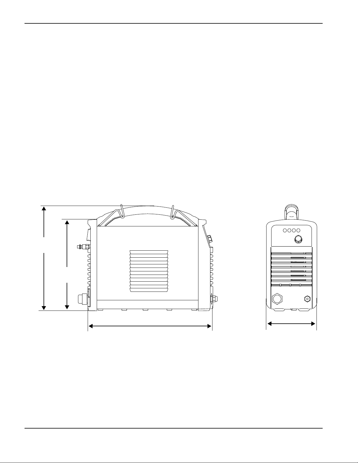
356 mm
(14 inches)
140 mm
(5.5 inches)
292 mm
(11.5 inches)
254 mm
(10 inches)
Carrying strap
Operator Manual
Safety and Compliance Manual
Quick Setup Card
For details on how to select the right set of consumables for a given cutting job, see
Choose the consumables on page 32.
Additional items may also ship with your Powermax30 XP depending on the configuration that you ordered, such as
instructional setup materials, a carrying case, leather cutting gloves, or protective glasses.
CSA units ship with a 120 V/15 A (NEMA 5-15P) adapter and a 240 V/20 A (NEMA 6-50P) adapter that connect to the
NEMA twist lock-style 240 V/20 A (NEMA L6-20P) plug wired to the power supply. CE and CCC units ship without a
plug on the power cord. See Power cord considerations on page 26 for more information.
You can order additional consumables and accessories – such as the carrying case, carrying strap, and a circle cutting
guide – from any Hypertherm distributor. See the Parts section on page 185 for a list of spare and optional parts.
Power supply dimensions
System weights
The following system weights include the hand torch with 4.6m (15foot) torch lead, a 4.6m (15foot) work lead with
ground clamp, and a 3.0 m (10 foot) power cord:
CSA systems: 9.7 kg (21.4 pounds)
CE and CCC systems: 9.5 kg (21.0 pounds)
18 Powermax30 XP Service Manual 808150 Revision 1
Page 19

1 – Specifications
Hypertherm system ratings
Rated open circuit voltage (U0)256VDC
Rated output current (I
Rated output voltage (U
Rated output voltage (U
= 200 – 240 VAC
U
1
Duty cycle at 40°C, U
(See data plate on power supply for more
information on duty cycle and for IEC ratings.)
Duty cycle at 40°C, U
(See data plate on power supply for more
information on duty cycle and for IEC ratings.)
)15A to 30A
2
) at U1= 120 VAC 83 VDC
2
) at
2
= 120 VAC
1
= 200 – 240 VAC
1
20% (I2=30A, U2=83V)
60% (I
100% (I
35% (I2=30A, U2=125V)
60% (I
100% (I
125 VDC
=17A, U2=83V)
2
=15A, U2= 83 V)
2
=23A, U2=125V)
2
=18A, U2= 125 V)
2
Operating temperature -10° to 40° C (14° to 104° F)
Storage temperature -25° to 55° C (-13° to 131° F)
Power factor (120 V – 240 V) 0.99 – 0.97
Input voltage (U
output (U
2MAX
, I
)/ Input current (I1) at rated
1
)
2MAX
200 – 240 V, 1-phase, 50/60 Hz, 22.5 – 18.8 A
120 V, 1-phase, 50/60 Hz, 25 A
(See Voltage configurations on page 25 for
more information.)
Gas type Air Nitrogen
Gas quality Clean, dry, oil-free 99.995% pure
Minimum required gas inlet flow and pressure 99.1 l/min at 4.7 bar (3.5 scfm at 68 psi)
Recommended gas inlet flow and pressure 113.3 l/min at 5.5 bar (4.0 scfm at 80 psi)
Maximum gas inlet pressure 9.3 bar (135 psi)
Powermax30 XP Service Manual 808150 Revision 1 19
Page 20
1 – Specifications
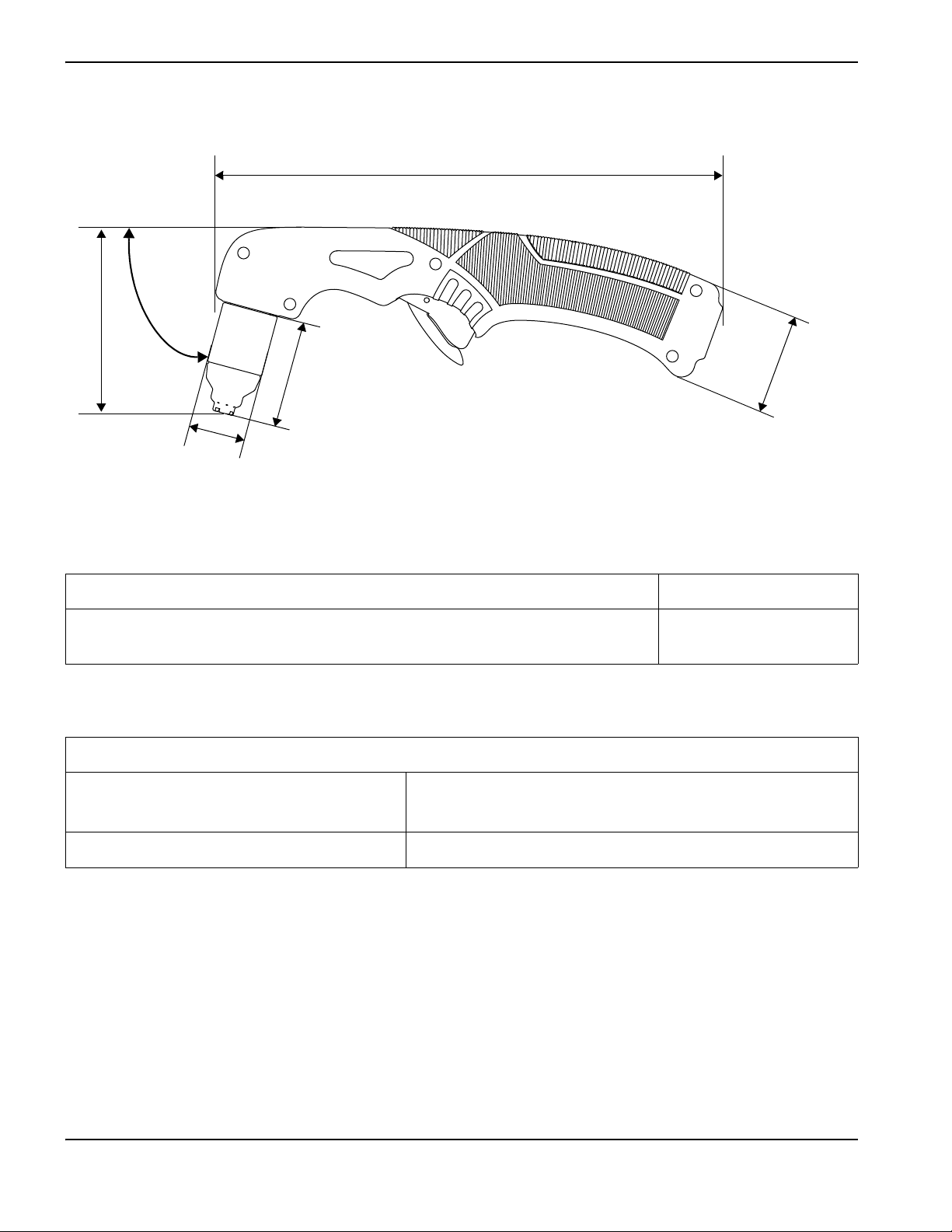
25 mm
(1.0 inch)
48 mm (1.9 inches)
230 mm (9.0 inches)
45 mm
(1.8 inches)
83 mm
(3.3 inches)
75°
Torch dimensions
Torch weight
Duramax LT torch with general-purpose (standard) consumables only 0.3 kg (0.75 pounds)
Duramax LT torch with general-purpose (standard) consumables and 4.6m (15foot)
lead (with strain relief)
1.1kg (2.35pounds)
Cutting specifications
240 V (with general-purpose [standard] consumables)
Recommended cut capacity 9 mm (3/8 inch) at 500 mm/minute (20 inches/minute)
12 mm (1/2 inch) at 250 mm/minute (10 inches/minute)
Severance cut capacity 15 mm (5/8 inch) at 125 mm/minute (5 inches/minute)
120 V: Use the FineCut nozzle and deflector for cutting on 120 V input circuits. When you operate the system at the
maximum recommended output of 25 A, the cut capacities are:
6 mm (1/4 inch) at 480 mm/minute (19 inches/minute)
9 mm (3/8 inch) at 200 mm/minute (8 inches/minute)
12 mm (1/2 inch) at 75 mm/minute (3 inches/minute)
To understand the differences between the general-purpose and FineCut consumables,
and for guidelines on selecting the right set for your cutting applications, see Choose
the consumables on page 32.
20 Powermax30 XP Service Manual 808150 Revision 1
Page 21

1 – Specifications
s
Symbols and marks
Your Hypertherm product may have one or more of the following markings on or near the data plate. Due to differences
and conflicts in national regulations, not all marks are applied to every version of a product.
S mark
The S mark indicates that the power supply and torch are suitable for operations carried out in
environments with increased hazard of electrical shock according to IEC 60974-1.
CSA mark
Hypertherm products with a CSA mark meet the United States and Canadian regulations for product
safety. The products were evaluated, tested, and certified by CSA-International. Alternatively, the product
may have a mark by one of the other Nationally Recognized Testing Laboratories (NRTL) accredited in
both the United States and Canada, such as Underwriters Laboratories, Incorporated (UL) or TÜV.
CE mark
The CE marking signifies the manufacturer’s declaration of conformity to applicable European directives
and standards. Only those versions of Hypertherm products with a CE marking located on or near the
data plate have been tested for compliance with the European Low Voltage Directive and the European
Electromagnetic Compatibility (EMC) Directive. EMC filters needed to comply with the European
EMC Directive are incorporated within versions of the product with a CE marking.
Eurasian Customs Union (CU) mark
CE versions of Hypertherm products that include an EAC mark of conformity meet the product safety and
EMC requirements for export to Russia, Belarus, and Kazakhstan.
GOST-TR mark
CE versions of Hypertherm products that include a GOST-TR mark of conformity meet the product safety
and EMC requirements for export to the Russian Federation.
C-Tick mark
CE versions of Hypertherm products with a C-Tick mark comply with the EMC regulations required for
sale in Australia and New Zealand.
CCC mark
The China Compulsory Certification (CCC) mark indicates that the product has been tested and found
compliant with product safety regulations required for sale in China.
UkrSEPRO mark
The CE versions of Hypertherm products that include a UkrSEPRO mark of conformity meet the product
safety and EMC requirements for export to the Ukraine.
Serbian AAA mark
CE versions of Hypertherm products that include a AAA Serbian mark meet the product safety and EMC
requirements for export to Serbia.
Powermax30 XP Service Manual 808150 Revision 1 21
Page 22

1 – Specifications
Direct current (DC)
Alternating current (AC)
Plasma torch cutting
AC input power connection
The terminal for the external
protective (earth) conductor
I Power is ON
O Power is OFF
An inverter-based power
source
Volt/amp curve, “drooping”
characteristic
Power is ON (LED)
Inlet gas pressure fault (LED)
Missing or loose consumables
(LED)
Power supply is overheated
(LED)
f
1
f
2
1~
AC
AC
Noise levels
This plasma system may exceed acceptable noise levels as defined by national and local codes. Always wear proper ear
protection when cutting. Any noise measurements taken depend on the specific environment in which the system is used.
Refer to Noise can damage hearing in the Safety and Compliance Manual (80669C) included with your system.
In addition, you can find an Acoustical Noise Data Sheet for your system in the Hypertherm downloads library at
https://www.hypertherm.com
:
1. Click “Downloads library.”
2. Select a product from the “Product type” menu.
3. Select “Regulatory” from the “Category” menu.
4. Select “Acoustical Noise Data Sheets” from the “Sub Category” menu.
IEC symbols
The following symbols may appear on the power supply data plate, control labels, switches, and LEDs.
22 Powermax30 XP Service Manual 808150 Revision 1
Page 23

Section 2
Power Supply Setup
Unpack the Powermax system
1. Verify that you received all items on your order in good condition. Contact your distributor if any parts are damaged or
missing. (See System contents on page 24.)
2. Inspect the system for damage that may have occurred during shipment. If you find evidence of damage, refer to
Claims. All communications regarding this equipment must include the model number and the serial number located
on the bottom of the power supply.
3. Before you set up and operate this Hypertherm system, read the separate Safety and Compliance Manual (80669C)
included with your system for important safety information.
Claims
Claims for damage during shipment – If your unit was damaged during shipment, file a claim with the carrier. You
can contact Hypertherm for a copy of the bill of lading. If you need additional assistance, call the nearest Hypertherm
office listed in the front of this manual.
Claims for defective or missing merchandise – If any component is missing or defective, contact your
Hypertherm distributor. If you need additional assistance, call the nearest Hypertherm office listed in the front of this
manual.
Powermax30 XP Service Manual 808150 Revision 1 23
Page 24
2 – Power Supply Setup
1
2
3
4
5
6
7
8
11
9
10
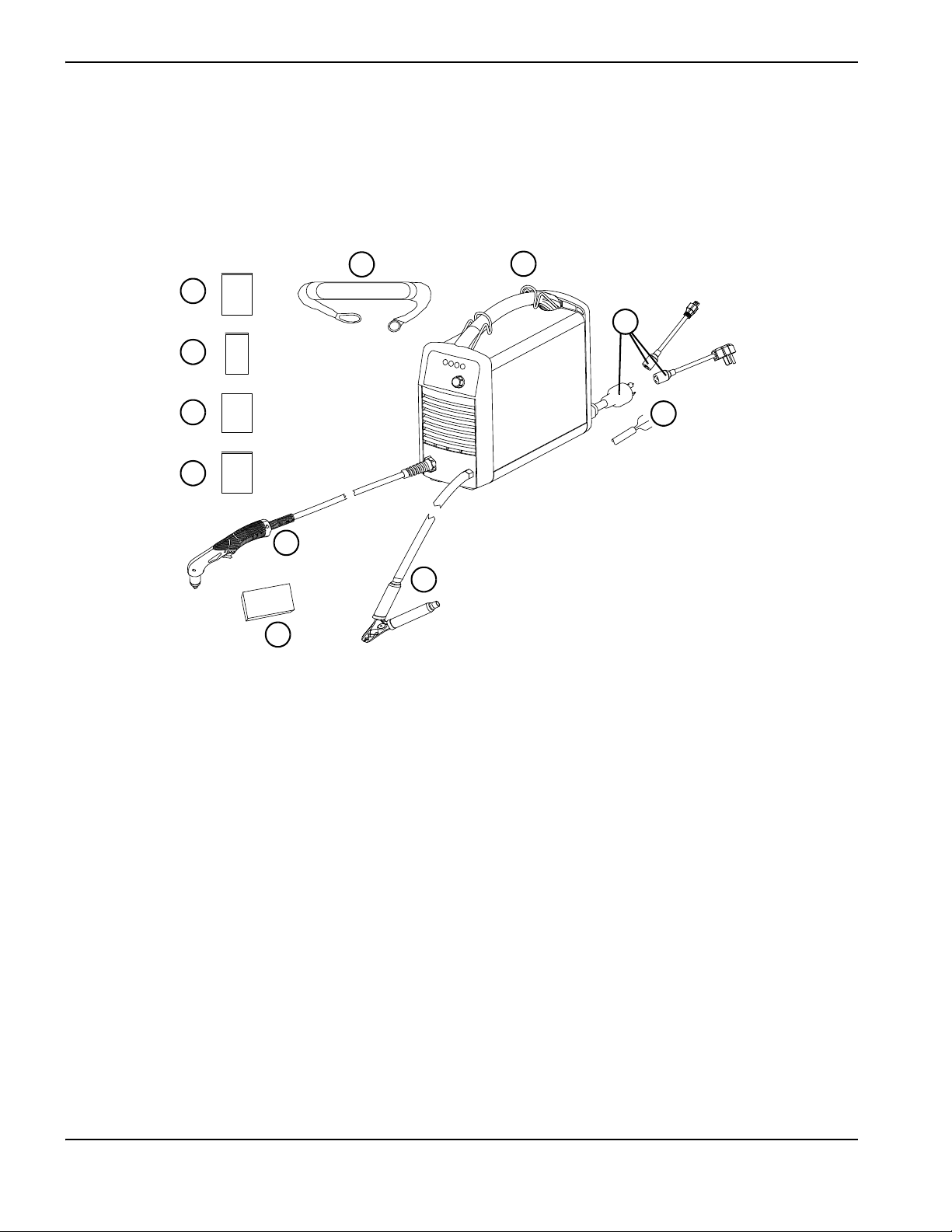
1
Operator Manual
2
Quick Setup Card
3
Registration card
4
Safety and Compliance Manual
5
Duramax LT torch with lead
6
Consumable kit
7
Ground clamp and work lead
8
CE/CCC power cord (no power plug included)
9
CSA power cord with power plug adapters
10
Power supply
11
Carrying strap
System contents
The following illustration shows the components typically included with all system configurations. Additional
components – such as setup instructions, a carrying case and protective glasses and gloves – may also be included with
your system, depending on the configuration you ordered.
The specific components included with the system are subject to change over time.
24 Powermax30 XP Service Manual 808150 Revision 1
Page 25

2 – Power Supply Setup
Position the plasma cutting system
Position the Powermax30 XP near an appropriate power receptacle. The system has a 3.0 m (10 foot) power cord.
Allow at least 0.25 m (10 inches) of space around the power supply for proper ventilation.
Place the power supply on a stable, level surface before using.
Do not use the system in rain or snow.
Prepare the electrical power
The system’s maximum output voltage varies based on the input voltage and the circuit’s amperage.
Additional factors must be considered when you are operating the system at an input power of 120 V, as tripped circuit
breakers can result under some conditions. For more information, see System operation guidelines on page 47 and
Troubleshooting guide on page 63.
Voltage configurations
The system automatically adjusts for proper operation at the current input voltage without requiring you to perform any
switching or rewiring. However, you must set the amperage adjustment knob to an appropriate output current and verify
that an appropriate set of consumables is properly installed in the torch. For more information, see Adjust the gas
pressure and output current on page 44 and Install the consumables on page 42.
The following table shows the maximum rated output for typical combinations of input voltage and amperage. The output
setting you need to use depends on the thickness of the metal and is limited by the input power to your system.
Input voltage circuit* Rated output
Input current at rated
output
kVA
Recommended
consumables
†
120 V, 15 A 20 A, 83 V 16.4 A 2.0 FineCut
120 V, 20 A 25 A, 83 V 20.5 A 2.5 FineCut
120 V, 30 A 30 A, 83 V 25 A 3.0 FineCut
200 – 240 V, 20 A 30 A, 125 V 22.5 – 18.8 A 4.5 General-purpose or FineCut
* Input voltages can be ±10% of the values in this table.
†
See Choose the consumables on page 32 for an explanation of general-purpose (standard) and FineCut consumables.
CAUTION!
A circuit capable of 20 A/120 V or 20 A/240 V is required for proper operation. Protect the circuit with
appropriately sized slow-blow (time-delay) fuses or circuit breakers.
Powermax30 XP Service Manual 808150 Revision 1 25
Page 26
2 – Power Supply Setup
Requirements for grounding
Properly ground the system as follows to ensure personal safety, proper operation, and to reduce electromagnetic
interference (EMI):
The system must be grounded through the power cord according to national and local electrical codes.
Single-phase service must be of the three-wire type with a green (CSA) or green/yellow (CE/CCC) wire for the
protective earth ground and must comply with national and local requirements. Do not use a two-wire service.
Refer to the Safety and Compliance Manual (80669C) for more information.
Power cord considerations
This system ships with a CSA, CE, or CCC power cord configuration. See Exterior, rear on page 187 for part number
information.
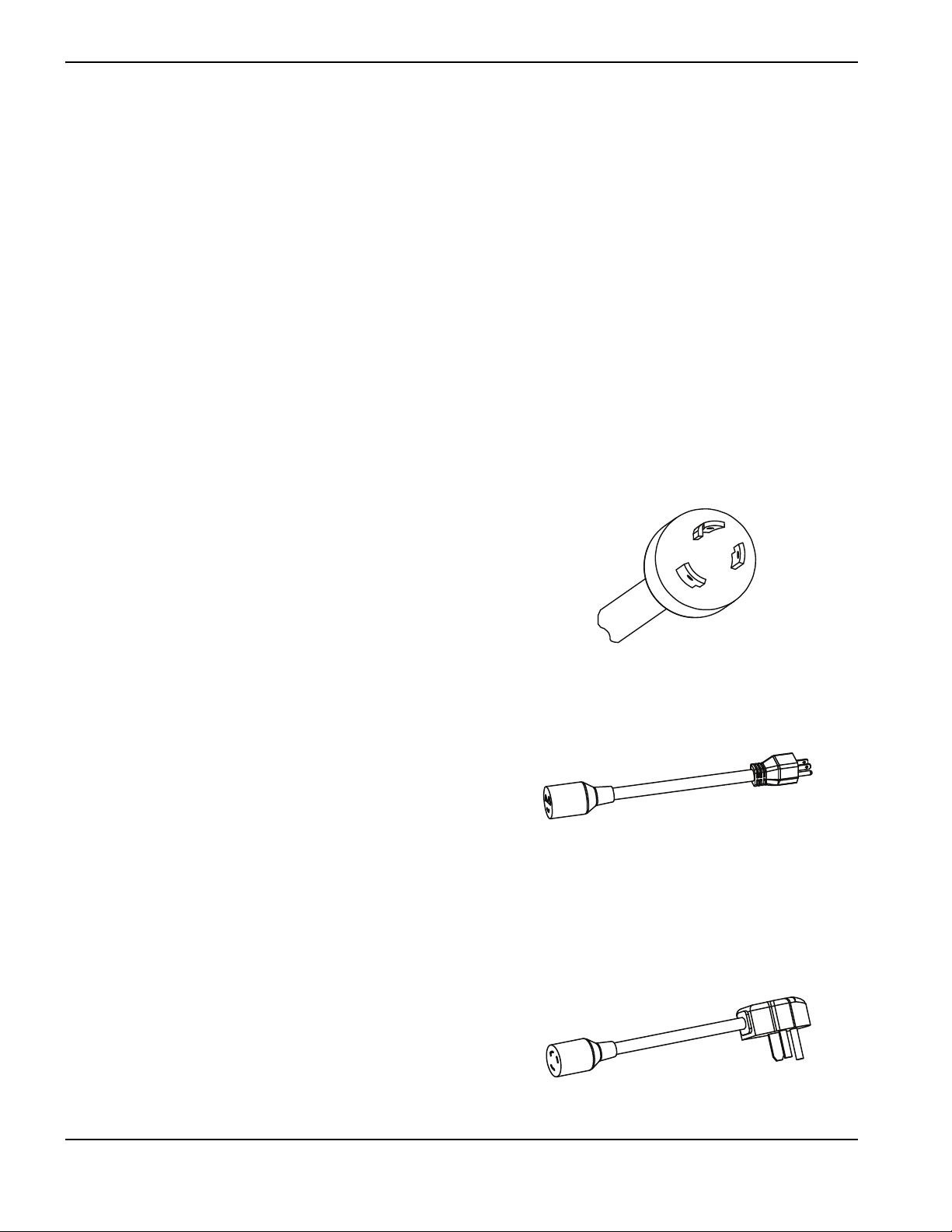
CSA power cords and plugs
CSA configurations include the following plug and adapters.
The power cord is equipped with a NEMA twist
lock-style plug (NEMA L6-20P) appropriate for
use on a 240 V/20 A circuit with a NEMA twist
lock-style outlet.
To operate the system on a lower amperage circuit,
attach the female end of the 120 V/15 A
(NEMA 5-15P) plug adapter to the power supply’s
NEMA twist lock-style plug.
Do not set the amperage adjustment knob above
20 A, or you may trip the circuit breaker. See Adjust
the gas pressure and output current on page 44.
To operate the system on a 240 V/20 A circuit,
attach the female end of the 240 V/20 A
(NEMA 6-50P) plug to the power supply’s NEMA
twist lock-style plug.
26 Powermax30 XP Service Manual 808150 Revision 1
Page 27
2 – Power Supply Setup
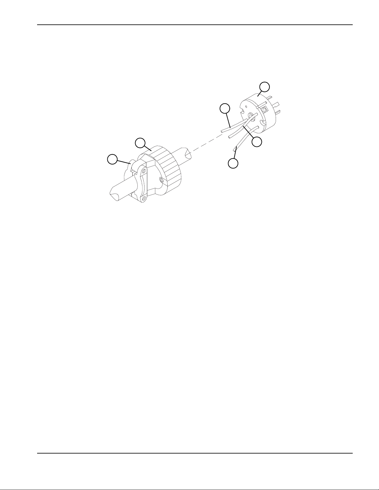
1
2
3
4
5
6
1
Cord grip
2
Outer shell
3
To line 1 terminal (brown)
4
220 V (CCC) or 230 V (CE) plug
5
To line 2 terminal (blue)
6
To ground terminal (green/yellow)
CE and CCC power cords
CE and CCC configurations ship without a plug on the power cord. To operate at 220 V (CCC) or 230 V (CE), obtain
the correct plug for your unit and location and have it installed by a licensed electrician.
1. Strip back the cord insulation to separate wires 3, 5, and 6.
2. Remove each wire’s insulation to allow good contact with the plug terminals.
3. Make the connections.
4. Reinstall the outer shell and cord grip, and tighten the cord grip’s screws until snug. Do not overtighten.
Powermax30 XP Service Manual 808150 Revision 1 27
Page 28
2 – Power Supply Setup
A
1
1
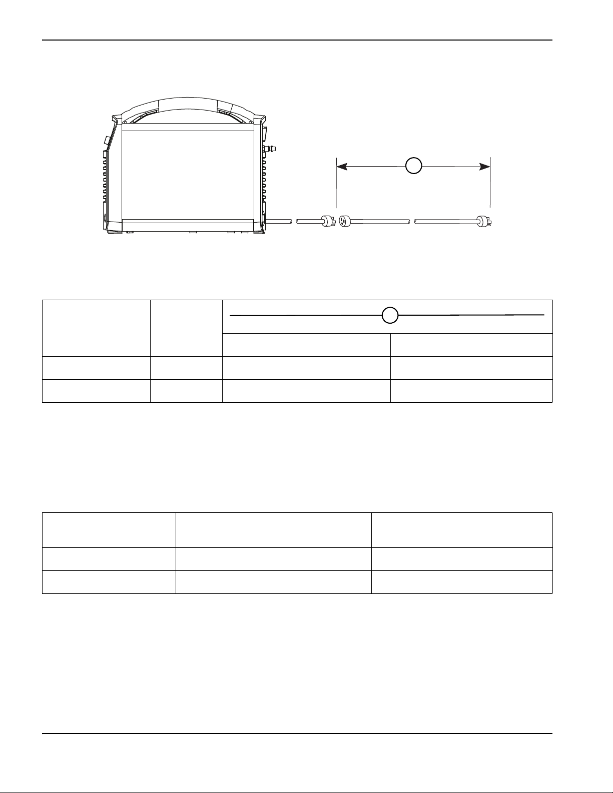
Extension cord recommendations
Use an extension cord of an appropriate wire gauge for the cord length and system voltage. Use a cord that meets
national and local codes.
Input voltage Phase
Recommended cord gauge size Length
120 VAC 1 4 mm
240 VAC 1 2 mm
Extension cords can cause the machine to receive less input voltage than the output of
the circuit. This can limit the operation of your system.
Generator recommendations
Generators used with this system should produce 240 VAC.
Engine drive rating
5.5kW 30A Full
4kW 25A Limited
Adjust the cutting current as needed based on the generator rating, age, and condition.
Engine drive output current
1-phase (CSA/CE/CCC)
2
(12 AWG) Up to 16 m (53 feet)
2
(14 AWG) Up to 40.5 m (133 feet)
Performance (arc stretch)
If a fault occurs while using a generator, turn OFF the system and wait approximately
60 seconds before turning it ON again. Turning the power switch quickly to OFF and
ON again (called a “quick reset”) may not clear the fault.
28 Powermax30 XP Service Manual 808150 Revision 1
Page 29
2 – Power Supply Setup
The recommended inlet pressure while gas is flowing is
5.5 – 6.9 bar (80 – 100 psi).
Prepare the gas supply
The gas supply can be shop-compressed or cylinder-compressed.You must use a high-pressure regulator on either type
of supply, and the regulator must deliver gas to the filter on the power supply at 99.1 l/min at 4.7 bar (3.5 scfm at 68 psi).
To ensure adequate pressure to the power supply, set the regulator between 5.5 and 6.9 bar (80 and 100 psi).
The system contains an internal filter element, but additional filtration may be required depending on the quality of the gas
supply. If gas supply quality is poor, cut speeds decrease, cut quality deteriorates, cutting thickness capability decreases,
and the life of the consumables shortens. For optimal performance, the gas should have a maximum:
Particle size of 0.1 micron at a maximum concentration of 0.1 mg/m
Dew point of -40° C (-40° F)
Oil concentration of 0.1 mg/m
3
(per ISO 8573-1 Class 1.2.2)
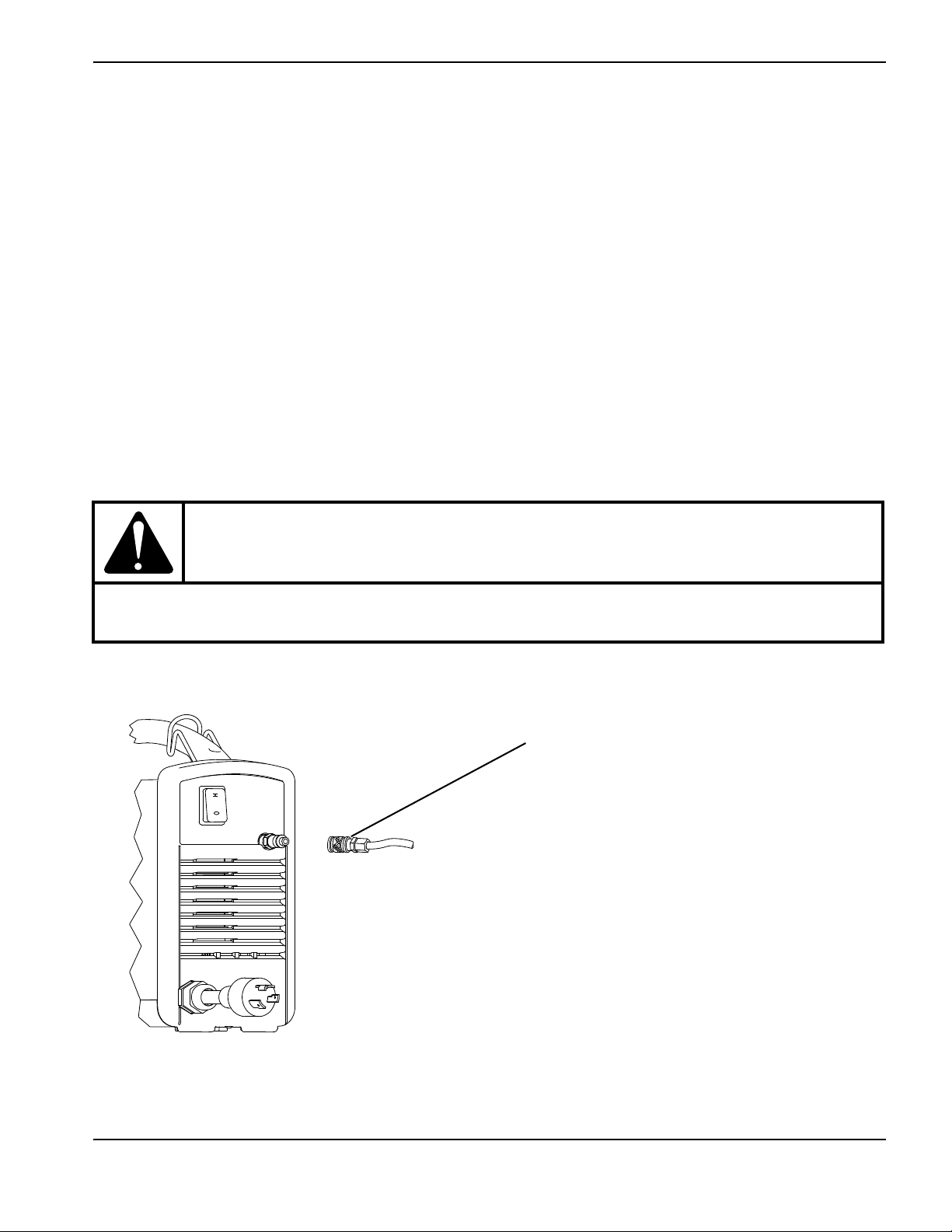
Connect the gas supply
Connect the gas supply to the power supply using an inert gas hose with a 6.3 mm (1/4 inch) or greater internal diameter
and an industrial interchange quick-disconnect coupler (for CSA models) or a G-1/4 BSPP threaded coupling (for CE
and CCC models).
3
CAUTION!
Some air compressors use synthetic lubricants containing esters that damage the polycarbonates
used in the air filter bowl.
Powermax30 XP Service Manual 808150 Revision 1 29
Page 30
2 – Power Supply Setup
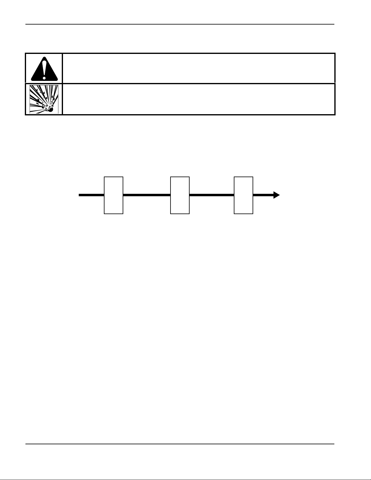
Gas supply Power supply
Oil vapor filterOil filterWater and particle filter
WARNING!
The air filter bowl may explode if the gas supply pressure exceeds 9.3 bar (135 psi).
Additional gas filtration
When site conditions introduce moisture, oil, or other contaminants into the gas line, use a three-stage coalescing
filtration system, such as the Eliminizer filter kit (128647) available from Hypertherm distributors. A three-stage filtering
system works as follows to clean contaminants from the gas supply.
Install the filtering system between the quick-disconnect coupler and the power supply.
30 Powermax30 XP Service Manual 808150 Revision 1
Page 31

Section 3
1
2
3
4
5
6
1
Handle
2
Shield (shown) or deflector
3
Retaining cap
4
Safety catch
5
Trigger (red)
6
Screws (5)
Torch Setup
Introduction
The Powermax30 XP includes the Duramax LT hand torch. This section explains how to set up and operate your torch. To
achieve optimal consumable life and cut quality, follow the instructions in this manual.
Hand torch components
Powermax30 XP Service Manual 808150 Revision 1 31
Page 32

3 – Torch Setup
I
O
Consumable life
Consumable life varies based on the following factors:
Thickness of the metal
Length of the average cut
Gas supply quality (presence of oil, moisture, or other contaminants)
Type of cutting (piercing decreases life when compared to edge cutting)
Pierce height
Consumables (FineCut or general-purpose)
Hypertherm does not recommend the use of any other consumables in the Duramax LT
torch except for those listed in this section, which are designed specifically for this system.
The use of any other consumables could adversely affect system performance.
Although largely dependent on the factors listed above, as a general rule, the consumables last approximately 1 to
2 hours of actual “arc on” time.
If the consumables’ life is shorter than expected or the cut quality is poor, verify that you are using the correct combination
of consumables. (See the following topic, Choose the consumables.) Under normal conditions, the nozzle wears out first.
For optimal cutting performance, always replace the nozzle and the electrode together.
See Hand torch operation on page 48 for more information about proper cutting techniques.
Choose the consumables
WARNING!
INSTANT-ON TORCHES
PLASMA ARC CAN CAUSE INJURY AND BURNS
The plasma arc ignites immediately when you press the torch trigger. Make
sure the power is OFF before changing consumables.
The Duramax LT hand torch ships with general-purpose (standard) consumables installed. The general-purpose
consumables are designed for a broad range of cutting applications.
Also included with your system is at least one FineCut nozzle and deflector. The FineCut consumables are designed to
achieve more finely detailed results on thin gauge metal.
The retaining cap, swirl ring, and electrode are the same for both sets of consumables.
The consumables that you choose should be determined by the:
Input power
Amperage output setting
32 Powermax30 XP Service Manual 808150 Revision 1
Page 33

3 – Torch Setup
General-purpose nozzle Shield
FineCut nozzle
Deflector
Etched rings
Etched rings
Thickness of the metal you plan to cut
The amperage output setting you need to use depends on the thickness of the metal you are planning to cut and is limited
by the input power to your system. See Voltage configurations on page 25.
Although the visual differences between the general-purpose (standard) and FineCut consumable parts
are minor, installing the wrong combination of consumables will affect the life of the parts as well as the
cut quality.
Hypertherm does not recommend the use of any other consumables in the Duramax LT
torch except for those listed in this section, which are designed specifically for this system.
The use of any other consumables could adversely affect system performance.
Figure 1 and Figure 2 illustrate the differences between the general-purpose and FineCut nozzles and between the
deflector and the shield. The FineCut consumables have rings or grooves etched onto them (as shown in Figure 2) to
help you distinguish them from the general-purpose consumables.
Figure 1 – General-purpose (standard)
Figure 2 – FineCut
Using the cut charts
The following topics provide cut charts for each set of consumables. Use these cut charts to guide you in selecting the
consumables and cutting current based on the thickness and type of the metal you need to cut.
The maximum cut speeds listed in the cut charts are the fastest possible speeds to cut metal without regard to cut quality.
Recommended cut speeds are a starting point for finding the best quality cut (best angle, least dross, and best cut
surface finish). Adjust the cutting speed for your application to obtain the desired cut quality.
When cutting thin metal – 3 mm (10 gauge) or thinner – you may achieve a higher cut quality by using the FineCut
consumables and cut charts.
Powermax30 XP Service Manual 808150 Revision 1 33
Page 34

3 – Torch Setup
5
4
3
2
1
6
1
To rc h
2
Electrode (420120)*
3
Swirl ring (420211)
4
Nozzle (420118)*
5
Retaining cap (420114)
6
Shield (420116)
General-purpose (standard) consumables
Use the general-purpose (or standard) consumables to cut thicker metals that do not require cuts that are as finely
detailed. (See Voltage configurations on page 25 and System operation guidelines on page 47.) This set includes an
electrode, swirl ring, general-purpose nozzle, retaining cap, and shield. The general-purpose nozzle must be installed only
with the shield, not the deflector.
Cutting at 120 V with the general-purpose consumables is not recommended.
Figure 3 – General-purpose (standard) consumable set
* Order the general-purpose (standard) nozzle and electrode together using kit 428243. This kit contains 2 nozzles and 2 electrodes.
Replace the nozzle and electrode at the same time.
34 Powermax30 XP Service Manual 808150 Revision 1
Page 35

240V/30A cutting
General-purpose (standard) consumables
Metric
Material thickness (mm) Material Arc current (A)
1
2 7530
3 4185
5 1835
8* 780
12* 320
16* 175
1
2 5635
3 2910
5 1245
8* 575
10* 360
13* 215
3
5 2115
8* 785
10* 425
13* 205
Mild steel 30
Stainless steel 30
Aluminum 30
3 – Torch Setup
Maximum cut speed
(mm/minute)
†
101 6 0
8355
3555
English
Material thickness
(gauge/inches)
Material Arc current (A)
18 GA
10 G A 110
1/4 40
3/8* 22
Mild steel 30
1/2* 10
5/8* 7
18 GA
10 G A 70
1/4 31
Stainless steel 30
3/8* 15
1/2* 9
1/8
1/4 45
3/8* 18
Aluminum 30
1/2* 9
* To cut material thicker than 6 mm (1/4 inch), start the torch at the edge of the workpiece.
†
Maximum cut speed is limited by the test table’s maximum speed (10160 mm/minute or 400 inches/minute).
Maximum cut speed
(inches/minute)
†
400
306
135
Powermax30 XP Service Manual 808150 Revision 1 35
Page 36

3 – Torch Setup
5
4
3
2
1
6
1
To rc h
2
Electrode (420120)*
3
Swirl ring (420211)
4
Nozzle (420117)*
5
Retaining cap (420114)
6
Deflector (420115)
FineCut consumables
Use the FineCut consumables for detailed cutting on thin gauge metal. The FineCut consumable set uses a FineCut
nozzle and a deflector with the same electrode, swirl ring, and retaining cap used in the general-purpose consumable set.
The FineCut nozzle must be installed only with the deflector, not the shield. Using the shield results in poor cut quality and
increased power demand because the torch-to-work distance is too great.
For guidelines on cutting with 120 V input, see Recommendations for cutting at 120 V on page 49.
Figure 4 – FineCut consumable set
* Order the FineCut nozzle and electrode together using kit 428244. This kit contains 2 nozzles and 2 electrodes. Replace the nozzle
and electrode at the same time.
36 Powermax30 XP Service Manual 808150 Revision 1
Page 37

120 V / 25 A cutting
FineCut consumables
Metric
Material thickness (mm) Material Arc current (A)
1
2 3570
3 1745
5 905
6 590
7
* 280
1
2 2860
3 1500
5 825
6 515
7
* 205
1
2 5130
3 2170
5 920
7
* 120
Mild steel 25
Stainless steel 25
Aluminum 25
3 – Torch Setup
Maximum cut speed
(mm/minute)
†
101 6 0
8390
†
101 6 0
English
Material thickness
(gauge/inches)
Material Arc current (A)
18 GA
16 GA 205
14 GA 150
12 GA 80
Mild steel 25
10 G A 55
1/4 19
18 GA
16 GA 160
14 GA 120
12 GA 65
Stainless steel 25
10 G A 52
1/4 16
1/25
1/16 250
1/8 65
Aluminum 25
1/4 15
* To cut material thicker than 6 mm (1/4 inch), start the torch at the edge of the workpiece.
†
Maximum cut speed is limited by the test table’s maximum speed (10160 mm/minute or 400 inches/minute).
Maximum cut speed
(inches/minute)
330
260
†
400
Powermax30 XP Service Manual 808150 Revision 1 37
Page 38

3 – Torch Setup
120 V / 30 A cutting
FineCut consumables
Metric
Material thickness (mm) Material Arc current (A)
1
2 6175
3 2420
5 1300
8
* 535
10
* 280
13
* 110
1
2 5755
3 2045
5 1135
8
* 410
10
* 170
1
2 6805
3 3285
5 1455
8
* 375
10
* 150
Mild steel 30
Stainless steel 30
Aluminum 30
Maximum cut speed
(mm/minute)
†
101 6 0
10025
†
101 6 0
English
Material thickness
(gauge/inches)
Material Arc current (A)
22 GA
18 GA 400
12 GA 112
10 G A 75
Mild steel 30
1/4 31
3/8
* 12
1/2
* 5
22 GA
18 GA 390
12 GA 90
10 G A 69
Stainless steel 30
1/4 24
3/8
* 9
1/25
1/16 325
1/8 10 5
Aluminum 30
1/4 22
3/8
* 8
* To cut material thicker than 6 mm (1/4 inch), start the torch at the edge of the workpiece.
†
Maximum cut speed is limited by the test table’s maximum speed (10160 mm/minute or 400 inches/minute).
Maximum cut speed
(inches/minute)
†
400
†
†
400
†
400
38 Powermax30 XP Service Manual 808150 Revision 1
Page 39

Section 4
I
O
I
O
Operation
Controls and indicators
Refer to the following topics to become familiar with the controls and LED indicators on the system before you begin
cutting.
Rear controls
ON (I) / OFF (O) power switch – Activates the system and its control circuits.
Powermax30 XP Service Manual 808150 Revision 1 39
Page 40

4 – Operation
20 25
AMPS
240 V
20 A
120 V
20 A
120 V
15 A
15
30
AC
AC
20 25
AMPS
240 V
20 A
120 V
20 A
120 V
15 A
15
30
Front controls and LEDs
Power ON LED (green) – When illuminated, this LED indicates that the power switch has been set to
ON (I) and that the safety interlocks are satisfied.
Gas pressure LED (yellow) – When illuminated, this LED indicates that the inlet gas pressure is below
2.8bar (40psi).
Torch cap LED (yellow) – When illuminated, this LED indicates that the consumables are loose,
improperly installed, or missing.
Temperature LED (yellow) – When illuminated, this LED indicates that the system’s temperature is
outside the acceptable operating range.
Some fault conditions cause one or more of the LEDs to blink. For
information on what these fault conditions are and how to clear them, see
Troubleshooting guide on page 63.
Amperage adjustment knob – Use this knob to set the output current
between 15 A and 30 A.
40 Powermax30 XP Service Manual 808150 Revision 1
Page 41

Operate the Powermax30 XP
1
2
1
2
The following topics explain how to begin cutting with the Powermax30 XP.
Connect the electrical power and gas supply
Plug in the power cord and connect the gas supply line .
4–Operation
For information on connecting the gas supply to the power supply, see Prepare the gas supply on page 29.
For information on connecting the proper plug to the power cord, see Power cord considerations on page 26.
To understand which consumables to use and what cutting capacity to expect based on input voltage, see Choose
the consumables on page 32.
For information on electrical requirements and gas supply requirements for this system, see Power Supply Setup on
page 23.
Powermax30 XP Service Manual 808150 Revision 1 41
Page 42

4 – Operation
I
O
Install the consumables
WARNING!
INSTANT-ON TORCHES
PLASMA ARC CAN CAUSE INJURY AND BURNS
The plasma arc ignites immediately when you press the torch trigger. Make
sure the power is OFF before changing consumables.
To operate the Duramax LT torch, first verify:
1. The power switch is in the OFF (O) position.
2. A complete set of consumables is installed as shown in Figure 5.
3. You use only the shield (420116) with the general-purpose (standard) nozzle (420118).
To understand the differences between the general-purpose and FineCut consumables,
and for guidelines on selecting the right set for your cutting applications, see Choose the
consumables on page 32.
42 Powermax30 XP Service Manual 808150 Revision 1
Page 43

Figure 5
or
or
Tighten only to finger tight.
1
2
3 4
5
6
7
1 Electrode
2 Swirl ring
3 Nozzle (general-purpose)
4 Nozzle (FineCut)
5 Retaining cap
6 Shield (general-purpose)
7 Deflector (FineCut)
4–Operation
Powermax30 XP Service Manual 808150 Revision 1 43
Page 44

4 – Operation
I
O
I
O
Attach the ground clamp
Attach the ground clamp to the workpiece.
Verify that the ground clamp and the workpiece make good metal-to-metal contact.
Attach the ground clamp as close as possible to the area being cut to reduce exposure to electric and magnetic
fields (EMF) and to achieve the best possible cut quality.
Do not attach the ground clamp to the portion of the workpiece that you are cutting away.
Power ON the system
Set the ON/OFF switch to the ON (I) position.
Adjust the gas pressure and output current
The power ON LED and the gas pressure LED illuminate when there is insufficient gas pressure to the system. Use a
high-pressure regulator that is capable of delivering gas to the filter on the power supply at 99.1 l/min at 4.7 bar
(3.5 scfm at 68 psi). For more information on attaching the gas supply, see Prepare the gas supply on page 29.
1. Set the regulator between 5.5 and 6.9 bar (80 and 100 psi).
2. Turn the amperage knob to the desired output current based on the input voltage, circuit size, and consumables.
44 Powermax30 XP Service Manual 808150 Revision 1
Page 45

Use only the FineCut consumables
120 V
420116
420118
FineCut
420115
420117
20 25
AMPS
240 V
20 A
120 V
20 A
120 V
15 A
15
30
Gray shading
20 25
AMPS
240 V
20 A
120 V
20 A
120 V
15 A
15
30
Blue shading
20 25
AMPS
240 V
20 A
120 V
20 A
120 V
15 A
15
30
when operating the system on a
120 V input circuit.
Operating the system on a 120 V, 15 A circuit
Set the amperage below 20 A, as indicated by the
gray shading around the knob (the inner ring).
Use only the FineCut nozzle (420117) and deflector
(420115); do not use the general-purpose (standard)
nozzle (420118) or shield (420116).
Verify that nothing else is drawing power from the
circuit.
4–Operation
Operating the system on a 120 V, 20 A circuit
Set the amperage below 25 A, as indicated by the
blue shading around the knob (the middle ring).
Use only the FineCut nozzle (420117) and deflector
(420115); do not use the general-purpose (standard)
nozzle (420118) or shield (420116).
Verify that nothing else is drawing power from the
circuit.
Operating the system on a 240 V, 20 A circuit
Set the amperage between 15 – 30 A.
Use either the general-purpose (standard) or the
FineCut consumables.
Do not mix the general-purpose and FineCut
consumables. Use one set or the other.
See Voltage configurations on page 25 for more
information.
Powermax30 XP Service Manual 808150 Revision 1 45
Page 46

4 – Operation
Check the indicator LEDs
Verify that the green power ON LED on the front of the power supply is illuminated and that none of the other LEDs are
illuminated or blinking.
If the temperature, torch cap sensor, or gas pressure LEDs illuminate or blink, or if the power ON LED blinks, correct the
fault condition before continuing. See Troubleshooting guide on page 63 section for more information.
Verify the system is ready
When the power ON LED illuminates, none of the other LEDs illuminate or blink, and the amperage knob is set, the
system is ready for use.
Understand duty-cycle limitations
The duty cycle is the percentage of time out of 10 minutes that a plasma arc can remain on when operating at an ambient
temperature of 40° C (104° F).
With input power of 120 V:
At 30 A, the arc can remain on for 2.0 minutes out of 10 minutes without causing the unit to overheat (20% duty
cycle).
At 17 A, the arc can remain on for 6 minutes out of 10 (60%).
At 15 A, the arc can remain on for 10 minutes out of 10 (100%).
With input power of 240 V:
At 30 A, the arc can remain on for 3.5 minutes out of 10 (35% duty cycle).
At 23 A, the arc can remain on for 6 minutes out of 10 (60%).
At 18 A, the arc can remain on for 10 minutes out of 10 (100%).
When the duty cycle is exceeded, the system overheats, the temperature LED illuminates, the arc shuts off, and the
cooling fan continues to run. To resume cutting, wait for the temperature LED to extinguish.
The fan may run during normal operation of the system.
46 Powermax30 XP Service Manual 808150 Revision 1
Page 47

4–Operation
System operation guidelines
To achieve the highest level of performance:
Operate the system at an input power of 240 VAC whenever possible.
Avoid using an extension cord whenever possible.
If you must use an extension cord, use a heavy conductor cord of the shortest possible
length. See Extension cord recommendations on page 28.
If you are operating your system on a 120 V, 15 A circuit, do not set the amperage higher than 20 A. See Voltage
configurations on page 25.
For best results when operating your system on a 120 V, 15 A circuit:
Do not connect anything else that will draw power from the same circuit.
Be aware that extension cords can reduce the voltage to the machine from what is output by the circuit. This
reduction in power can impair cutting performance and increase the probability of tripping the circuit breaker.
Cutting a thicker workpiece with the general-purpose (standard) consumables requires a higher amperage setting. It
is preferable to operate on a higher rated circuit (240 V / 30 A) when cutting thicker metal. See Voltage
configurations on page 25.
Additional techniques to reduce the frequency of tripped circuit breakers include:
Turn down the amperage adjustment knob.
Avoid stretching the arc. Instead, drag the torch on the workpiece as explained in Edge start on a workpiece on
page 50.
Powermax30 XP Service Manual 808150 Revision 1 47
Page 48

4 – Operation
1
2
3
Hand torch operation
WARNING!
INSTANT-ON TORCHES
PLASMA ARC CAN CAUSE INJURY AND BURNS
Plasma arc ignites immediately when you press the torch trigger. The plasma arc cuts quickly through
gloves and skin.
Keep hands, clothes, and objects away from the torch tip.
Do not hold the workpiece, and keep your hands clear of the cutting path.
Never point the torch toward yourself or others.
WARNING!
SPARKS AND HOT METAL
CAN INJURE EYES AND BURN SKIN
Always wear proper protective equipment including gloves and eye protection, and point the torch
away from yourself and others. Sparks and hot molten metal spray out from the nozzle.
Safety catch operation
The Duramax LT torch is equipped with a safety catch to prevent accidental firings. When you are ready to cut with the
torch, flip the safety catch forward (toward the torch head) and press the red torch trigger.
48 Powermax30 XP Service Manual 808150 Revision 1
Page 49

4–Operation
Hand torch cutting guidelines
With either set of consumables, drag the torch tip lightly on the workpiece to maintain a steady cut speed.
Sometimes the torch sticks slightly to the workpiece when you cut with the FineCut
consumables.
While cutting, make sure that sparks exit from the bottom of the workpiece. The sparks should lag slightly behind the
torch as you cut (15°–30° angle from vertical).
If sparks spray up, you are not cutting all the way through the workpiece. Move the torch more slowly, or, if possible,
increase the output current.
Hold the torch nozzle perpendicular to the workpiece so that the nozzle is at a 90° angle to the cutting surface, and
watch the arc as it cuts along the line.
Pulling the torch toward you along the cut is easier than pushing it or moving from side-to-side.
For straight-line cuts, use a straight edge as a guide. To cut circles, use a template or a radius cutter attachment (a
circle cutting guide). See Accessory parts on page 195 for the Hypertherm plasma cutting guide part numbers for
cutting circles and making bevel cuts.
If you fire the torch unnecessarily, you shorten the life of the nozzle and electrode.
Recommendations for cutting at 120 V
Use only the FineCut consumables.
Do not use an extension cord.
Verify nothing else is drawing power from the circuit.
Turn down the current adjustment knob to avoid tripping the breaker.
Powermax30 XP Service Manual 808150 Revision 1 49
Page 50

4 – Operation
Edge start on a workpiece
When cutting material thicker than 6 mm (1/4 inch), start the torch at the edge of the workpiece to prolong consumable
life.
1. With the ground clamp attached to the workpiece, hold the torch perpendicular (90°) to the workpiece and on the
edge.
2. Press the torch trigger to start the arc. You may need to pause at the edge until the arc has cut completely through
the workpiece.
3. Drag the torch lightly across the workpiece to proceed with the cut. Maintain a steady, even pace.
50 Powermax30 XP Service Manual 808150 Revision 1
Page 51

4–Operation
Pierce a workpiece
If the metal is thinner than 6 mm (1/4 inch), use piercing to cut an interior feature. Piercing shortens the life of the
consumables.
The type of pierce to perform depends on the thickness of the metal. Hypertherm recommends:
Straight pierce – For cutting metal that is thinner than 3 mm (1/8 inch).
Rolling pierce – For cutting metal that is 3 mm (1/8 inch) or thicker.
1. Attach the ground clamp to the workpiece.
2. Straight pierce: Hold the torch perpendicular (90°) to the workpiece.
Rolling pierce: Hold the torch at an approximate 30° angle to the workpiece with the torch tip within 1.5 mm
(1/16 inch) of it before firing the torch.
3. Straight pierce: Press the torch trigger to start the arc.
Rolling pierce: Press the torch trigger to start the arc while still at an angle to the workpiece, then slowly rotate the
torch to the perpendicular (90°) position.
4. Hold the torch in place while continuing to press the trigger. When sparks exit from the bottom of the workpiece, the
arc has pierced the metal.
Powermax30 XP Service Manual 808150 Revision 1 51
Page 52

4 – Operation
5. When the pierce is complete, drag the torch lightly along the workpiece to proceed with the cut.
Gouge a workpiece
You can use the Powermax30 XP with the general-purpose (standard) consumables for light gouging applications, such
as the removal of spot welds and tack welds.
The system does not require a dedicated set of consumables or a special mode setting
for gouging. However, do not use the FineCut consumables for gouging applications.
1. Hold the torch so that the torch tip is slightly above the workpiece before firing the torch.
2. Hold the torch at a 45° angle to the workpiece with a small gap between the torch tip and the workpiece. Press the
trigger to obtain a pilot arc. Transfer the arc to the workpiece.
52 Powermax30 XP Service Manual 808150 Revision 1
Page 53

4–Operation
45°
3. Maintain an approximate 45° angle to the workpiece as you feed into the gouge.
Push the plasma arc in the direction of the gouge you want to create. Keep a small distance between the torch tip
and the molten metal to avoid reducing consumable life or damaging the torch.
You can vary the gouge profile by varying the:
Speed of the torch over the workpiece
Torch-to-work standoff distance
Angle of the torch to the workpiece
System’s current output
Varying the gouge profile
Follow these recommendations to change the gouge profile as needed:
Increasing the speed of the torch will decrease width and decrease depth.
Decreasing the speed of the torch will increase width and increase depth.
Increasing the standoff of the torch will increase width and decrease depth.
Decreasing the standoff of the torch will decrease width and increase depth.
Increasing the angle of the torch (more vertical) will decrease width and increase depth.
Decreasing the angle of the torch (less vertical) will increase width and decrease depth.
Increasing the current of the power supply will increase width and increase depth.
Decreasing the current of the power supply will decrease width and decrease depth.
Powermax30 XP Service Manual 808150 Revision 1 53
Page 54

4 – Operation
Common hand-cutting faults
For more information on faults, see Troubleshooting guide on page 63.
The torch sputters and hisses, but does not produce an arc. The cause can be:
Overtightened consumables
The torch does not cut completely through the workpiece. The causes can be:
Cut speed is too fast
Worn consumables
Metal being cut is too thick for the selected amperage
Installation of the wrong consumables
Poor electrical contact between the ground clamp and the workpiece
Low gas pressure or low gas flow rate
Cut quality is poor. The causes can be:
Metal being cut is too thick for the selected amperage
Installation of the wrong consumables
Cut speed is too fast or too slow
Worn or damaged consumables
The arc sputters and consumables life is shorter than expected. The causes can be:
Moisture in the gas supply
Low gas pressure
Incorrect installation of the consumables
Installation of the wrong consumables
Minimizing dross
Dross is the molten metal that solidifies on the workpiece. Some amount of dross is always present when cutting with air
plasma. However, you can control the amount and type of dross by adjusting your system correctly for your application.
Low-speed dross forms when the torch’s cutting speed is too slow and the arc shoots ahead. It forms as a heavy, bubbly
deposit at the bottom of the cut and is usually easy to remove. Increase your speed to reduce this type of dross.
High-speed dross forms when the cutting speed is too fast and the arc lags behind. It forms as a thin, linear bead of solid
metal attached very close to the cut. It forms to the bottom of the cut and is often more difficult to remove. Decrease your
speed to reduce this type of dross.
Dross is more likely to form on warm or hot metal than on cool metal. For example, the
first cut in a series of cuts is likely to produce the least dross. As the workpiece heats up,
more dross may form on subsequent cuts.
Worn or damaged consumables may produce intermittent dross.
54 Powermax30 XP Service Manual 808150 Revision 1
Page 55

Section 5
Troubleshooting and System Tests
Theory of operation
Functional description
AC power enters the system through the power switch (S1) to the input diode bridges (D24, D30). The voltage from the
diode bridge supplies the power factor correction (PFC) boost converter, which provides a nominal 375 VDC bus
voltage. The bus voltage then supplies voltage and current to the inverter and the flyback circuit power supply (DC to DC
converter) on the power board (PCB2). The power board provides noise suppression and spike protection. A “soft start”
is implemented via the power board resistor and relay (K1).
The PFC boost converter consists of an insulated gate bipolar transistor (IGBT Q1), choke, and control circuit. It
provides a 375 VDC bus voltage when the input AC voltage is between 120 and 240 VAC.
The inverter consists of an IGBT (Q2), the power transformer, a current-sense transformer, and sections of the power
board. The inverter operates as a pulse-width, modulator-controlled bridge circuit that is rectified by the output
diode (D27).
The output circuitry consists of two current sensors located on the power board, the pilot arc IGBT (inside the
D27 module), and the output choke.
The control board’s microprocessor monitors and regulates the system’s operation and safety circuits. The amperage
adjustment knob sets the output current to the desired value between 15 A and 30 A. The system compares the
set-point to the output current by monitoring the current sensor and adjusting the pulse-width output of the inverter
IGBT (Q2).
Powermax30 XP Service Manual 808150 Revision 1 55
Page 56

5 – Troubleshooting and System Tests
Power OFF (O)
• Connect the gas supply to the gas fitting
on the power supply.
• Connect the work lead to the workpiece.
• Apply power at the line-voltage
disconnect box.
• Set the power switch (S1) to ON (I).
• The green power-ON LED illuminates,
indicating the system is ready for
operation.
• All the fault LEDs should be extinguished.
(See Troubleshooting guide on page 63.)
• Set the amperage adjustment knob to the
desired output current (between 15 A and
30 A) based on the input voltage and
circuit size.
• The power circuits are ready.
• Position the torch on the workpiece.
• Pull the plasma start trigger on the torch.
• The gas solenoid valve (V1) opens.
• The gas flow starts.
• The cutting arc starts.
• Drag the torch lightly across the
workpiece to make a cut.
• The workpiece drops after the cut.
• Release the plasma start trigger on the
torch.
• The arc extinguishes.
• Gas postflow continues for 20 seconds.
• The gas solenoid valve (V1) closes.
• The gas flow stops.
• Set the power switch (S1) to OFF (O).
Sequence of operation
56 Powermax30 XP Service Manual 808150 Revision 1
Page 57

5 – Troubleshooting and System Tests
Troubleshooting preparation
The complexity of the circuits requires that service technicians have a working knowledge of inverter power supply theory.
In addition to being technically qualified, technicians must perform all testing with safety in mind.
If questions or problems arise during servicing, call the Hypertherm Technical Services team listed in the front of this
manual.
Test equipment
Multimeter with a variety of test leads, including test hooks.
Troubleshooting procedures and sequence
When performing the troubleshooting procedures, refer to:
Safety and Compliance Manual (80669C) for detailed safety information.
Wiring Diagrams on page 199 for the system’s electrical schematic.
Power Supply Component Replacement on page 87 or Torch Component Replacement on page 171 for
replacement procedures.
Parts on page 185 for power supply components and torch components.
Power OFF (O) and disconnected
External inspection
Internal inspection
Initial resistance check
Power ON (I)
Troubleshooting guide
System tests
Powermax30 XP Service Manual 808150 Revision 1 57
Page 58

5 – Troubleshooting and System Tests
After the problem has been located and repaired, refer to Sequence of operation on page 56 to test the power supply for
proper operation.
WARNING!
ELECTRIC SHOCK CAN KILL
Turn OFF (O) the power and disconnect the electrical power before removing the cover
from the power supply. If the power supply is connected directly to a line disconnect box,
switch the line disconnect to OFF (O). In the U.S., use a “lock-out / tag-out” procedure
until the service or maintenance work is complete. In other countries, follow appropriate
national or local safety procedures.
Do not touch live electrical parts! If power is required for servicing, use extreme caution
when working near live electrical circuits. Dangerous voltages exist inside the power
supply that can cause serious injury or death.
Do not attempt to repair the power board or control board. Do not cut away or remove any
protective conformal coating from either board. To do so risks a short circuit between the
AC input circuit and the output circuit and may result in serious injury or death.
HOT PARTS CAN CAUSE SEVERE BURNS
Allow the power supply to cool before servicing.
MOVING BLADES CAN CAUSE INJURY
Keep hands away from moving parts.
STATIC ELECTRICITY CAN DAMAGE CIRCUIT BOARDS
Put on a grounded wrist strap before handling printed circuit boards.
58 Powermax30 XP Service Manual 808150 Revision 1
Page 59

5 – Troubleshooting and System Tests
External inspection
1. Inspect the exterior of the power supply for damage to the cover and external components, such as the power cord
and plug.
2. Inspect the torch and the torch lead for damage.
3. Inspect the consumables for damage or wear.
4. Repair or replace components as necessary.
Internal inspection
1. Set power switch to OFF (O), disconnect the power cord from the power source, and disconnect the gas supply.
2. Remove the power supply handle and cover. (See Remove the power supply cover on page 88.)
3. Remove the component barrier. (See Remove the component barrier on page 90.)
4. Inspect the inside of the power supply, especially the side with the power board. Look for broken or loose wiring
connections, burn and char marks, damaged components, and so on.
5. Repair or replace components as necessary.
Initial resistance check
All resistance values must be taken with the power cord disconnected and all internal power supply wires attached.
Perform the steps in Internal inspection (above) before continuing in this section.
The type of multimeter you use significantly affects the results of the tests in this section. The resistance values in this
manual are intended as a general reference point.
If resistance values indicate a problem based on the range of values provided in this section, isolate the problem by
removing wires attached to the resistance check points or component until the problem is found.
After the problem is located and repaired, see Sequence of operation on page 56 to test the power supply for proper
operation.
Powermax30 XP Service Manual 808150 Revision 1 59
Page 60

5 – Troubleshooting and System Tests
75 kΩ
Black (CSA)
Brown (CE/CCC)
Check the power switch
1. Set power switch to OFF (O), disconnect the power cord from the power source, and then set the power switch to
ON (I).
2. Check the resistance across the input leads.
Figure 6
3. Check the resistance from the input leads to ground to verify that it reads as open. For all power supplies, the
resistance from input to ground should read as > 20 MΩ.
With the electrical power disconnected and the power switch set to OFF (O), all circuits
should read as open.
The electrical value shown is ±25%. However, this range is intended only for reference. Resistance values can
vary widely depending on the type of multimeter and the polarity used to measure the readings.
4. Remove the consumables from the torch. If you do not remove the consumables, the resistance values will not read
correctly.
60 Powermax30 XP Service Manual 808150 Revision 1
Page 61

5 – Troubleshooting and System Tests
J22
WORK LEAD (BLK)
J16, red
J17, white
5. Check the output resistance for the values shown in the following table.
J16 and J17 are labeled on the component side of the power board. See Figure 7 for
locations on the back side of the power board.
Measure resistance from Approximate values
Work lead (J22) to nozzle (J16, red wire) 100 kΩ
Work lead (J22) to electrode (J17, white wire) 20 kΩ
Electrode (J17, white wire) to nozzle (J16, red wire) 120 kΩ
Work lead (J22), nozzle (J16, red wire), and electrode (J17, white wire) to
ground
>20MΩ
Figure 7
6. If you do not find any problems during the visual inspection or the initial resistance check, and the power supply is still
not operating correctly, see Troubleshooting guide on page 63.
Powermax30 XP Service Manual 808150 Revision 1 61
Page 62

5 – Troubleshooting and System Tests
1
2
4
5
6
7
8
9
10
3
1
Output diode and pilot arc IGBT module (D27)
2
Work lead connection (J22)
3
Input diode bridges (D24, D30)
4
PE (ground)
5
Power board (PCB2)
6
Power switch (S1)
7
PFC IGBT (Q1)
8
Flyback circuit
9
Inverter IGBT (Q2)
10
Control board (PCB1)
Power supply overview
Figure 8
62 Powermax30 XP Service Manual 808150 Revision 1
Page 63

5 – Troubleshooting and System Tests
AC
AC
Troubleshooting guide
This guide provides the most probable causes and solutions. Study the Powermax30 XP schematic on page 201 and
understand the Theory of operation on page 55 before troubleshooting. Before purchasing any major replacement
component, verify the problem with Hypertherm Technical Service or the nearest Hypertherm repair facility listed in the
front of this manual. See System tests on page 71 for detailed test procedures.
Problem This may mean Possible cause(s) Possible solution(s)
The power switch is set to
ON (I), but the power ON
LED is not illuminated.
The power ON LED and
the gas pressure LED
illuminate.
The power ON LED and
the temperature LED
illuminate.
• There is insufficient
voltage to the control
circuits or a
short-circuited power
component.
• There is insufficient
gas pressure to the
system.
• The system
overheated.
• The system is too
cold to operate.
• The system has no
incoming voltage or an
improper incoming
voltage.
• The power board is
faulty.
• The gas supply line is
not attached to the
system.
• The gas supply line has
a restriction.
• The air filter element is
dirty.
• The pressure switch is
not reading at least
2.8 bar (40 psi) on the
gas supply line.
• You have exceeded the
duty cycle. (See
Understand duty-cycle
limitations on
page 46.)
• The ambient
temperature is too low.
• Verify that the electrical power
is connected to an
appropriately sized circuit.
• Verify that the system did not
trip the circuit breaker.
•Perform Test 1 – voltage input
on page 74.
• Attach the gas supply.
• Inspect the gas supply line for
restrictions or damage, and
repair or replace if necessary.
• Inspect the air filter element,
and replace if necessary. (See
Replacing the air filter bowl and
air filter element on page 148.)
•Perform Test 9 – pressure
switch on page 86.
• Inspect the area around the
system to make sure that the
gas flow is not blocked.
• Let the system cool before
using it.
•Perform Te s t 8 – fan on
page 85.
• Let the system warm up before
using it.
Powermax30 XP Service Manual 808150 Revision 1 63
Page 64

5 – Troubleshooting and System Tests
AC
AC
AC
AC
Problem This may mean Possible cause(s) Possible solution(s)
The power ON LED
illuminates and the
temperature LED blinks.
•The system
overheated.
• The system is
continuously drawing
too much input current
for too long.
• You are operating the
system on a 120 VAC
input circuit while
using the
general-purpose
nozzle and shield.
• Let the system cool for
approximately 3 minutes before
using it.
• Turn down the cutting current.
See Adjust the gas pressure
and output current on page 44.
• Use only the FineCut
consumables when operating
the system on a 120 VAC input
circuit. See Choose the
consumables on page 32.
• Operate the system on a
240 VAC input circuit
whenever possible.
• Avoid stretching the arc. Drag
the torch on the workpiece. See
Edge start on a workpiece on
page 50.
• Operate the system without
using an extension cord. If you
must use an extension cord,
use a heavy conductor cord of
the shortest possible length.
See Extension cord
recommendations on page 28.
The power ON LED blinks. • The incoming voltage
is not correct.
The power ON LED and
the torch cap LED
• The cap-sensing
circuit is open.
illuminate.
The power LED illuminates
and the torch cap LED
blinks.
• The consumables are
stuck in an open or
closed position.
•The nozzle and
electrode are not
touching when the
torch trigger is pulled.
• The incoming voltage
is below 90 VAC or
above 285 VAC.
• The consumables are
loose, incorrectly
installed, or missing.
• The cap-sensor switch
is faulty.
• The consumables are
installed incorrectly,
worn, or damaged.
• The torch plunger is
stuck.
• The torch or torch lead
has a broken wire.
•Perform Test 1 – voltage input
on page 74.
• Verify that the consumables are
installed correctly.
•Perform Te s t 7 – torch
cap-sensor on page 84.
• Verify that the consumables are
installed correctly.
• Inspect the consumables for
wear, and replace if necessary.
•Perform Test 5 – torch stuck
open or torch stuck closed on
page 81.
64 Powermax30 XP Service Manual 808150 Revision 1
Page 65

5 – Troubleshooting and System Tests
AC
AC
Problem This may mean Possible cause(s) Possible solution(s)
The gas pressure and
temperature LEDs blink
when the system is
powered ON (I).
The temperature, gas
pressure, and power ON
LEDs blink, and the torch
cap LED illuminates.
All four LEDs blink when
the system is powered ON
(I).
• The system was
powered on while the
plasma start signal
was being sent.
• The inverter is
saturated.
• A major fault has
occurred in the power
supply.
• The system was
powered on with the
torch trigger being
pulled.
• The start circuit is
stuck closed.
• The inverter is in an
over-current condition.
• The torch was
repeatedly fired with
worn out consumables.
• The fan, solenoid valve,
control board, or
power board is faulty.
• Release the torch trigger and
reset the system by turning it
OFF (O), and then turn it ON (I)
again.
•Perform Test 6 – plasma start
on page 82.
• Install new consumables in the
torch (they may be corroded or
approaching end of life).
• If you continue to see this error,
replace the power board.
• The error LED on the control
board should be blinking. The
number of times it blinks
between pauses indicates
which components to test. See
Control board LEDs on
page 69.
The power-ON LED
illuminates but no fault
LEDs illuminate, and no
gas flows when you pull
the torch trigger.
Gas flows when the
system is powered ON (I).
• The start signal is not
reaching the control
board.
• The incoming gas
pressure is too high.
• The torch or torch lead
is damaged.
• The power board is
faulty.
• The control board is
faulty.
• The gas pressure from
the compressor or
cylinder is too high.
• The gas solenoid valve
is faulty.
• Inspect the torch and torch
lead, and replace if necessary.
• Verify that the control board
start LED illuminates when you
pull the trigger. If it does not,
perform Test 6 – plasma start
on page 82.
• Verify that the gas supply does
not exceed 9.3 bar (135 psi),
and reduce the pressure if
necessary.
•Perform Test 4 – solenoid valve
on page 80.
Powermax30 XP Service Manual 808150 Revision 1 65
Page 66

5 – Troubleshooting and System Tests
Problem This may mean Possible cause(s) Possible solution(s)
When you pull the torch
trigger, gas flows from the
torch, but the torch does
not fire or fires only for a
short period of time.
Arc goes out while cutting
or intermittently will not fire.
• The consumables,
torch, or torch lead
are not functioning
correctly.
• The gas pressure is
too low.
• The gas supply quality
is poor.
• There is a voltage
imbalance on the
power board.
•The work lead
connection is poor.
• The consumables are
worn or damaged.
• The torch or torch lead
is damaged.
• The gas supply line is
restricted.
• The air filter element is
dirty.
• The power board is
faulty.
• The work lead is
damaged or not
properly connected to
the workpiece.
• Inspect the consumables, torch,
and torch lead, and replace if
necessary.
• Inspect the gas supply line for
restrictions or damage.
• Inspect the air filter element,
and replace if necessary. (See
Replacing the air filter bowl and
air filter element on page 148.)
• Verify that the gas supply is
providing at least 4.5 bar
(65 psi).
•Perform Te s t 3 – V B U S a nd
voltage balance on page 78.
• Inspect for loose connections
at the ground clamp and at the
power supply, and repair if
necessary.
• Reposition the work lead on the
workpiece.
• Clean the cutting surface to
make a better connection with
the work lead.
When you pull the torch
trigger, the pilot arc starts
but then extinguishes
before the normal
5-second timeout period.
• The consumables,
torch, or torch lead is
not functioning
correctly.
• The gas pressure is
too low.
• The gas supply quality
is poor.
• There is a voltage
imbalance on the
power board.
• The consumables are
worn or damaged.
• The torch or torch lead
is damaged.
• The gas supply line is
restricted.
• The air filter element is
dirty.
• The power board is
faulty.
• Inspect the consumables, torch,
and lead, and replace if
necessary.
• Inspect the gas supply line for
restrictions or damage.
• Inspect the air filter element,
and replace if necessary. (See
Replacing the air filter bowl and
air filter element on page 148.)
• Verify that the gas supply is
providing at least 4.5 bar
(65 psi).
•Perform Te s t 3 – V B U S a nd
voltage balance on page 78.
66 Powermax30 XP Service Manual 808150 Revision 1
Page 67

5 – Troubleshooting and System Tests
Problem This may mean Possible cause(s) Possible solution(s)
The cut quality is poor, or
the cut does not sever the
metal.
The pilot arc extinguishes
when you move the plasma
arc off the workpiece while
still pulling the torch
trigger.
• The consumables are
not functioning
correctly.
• There is a poor work
lead connection.
• The output from the
power supply is too
low.
• The power board is
producing low
current.
• The extension cord is
not delivering
sufficient power to the
power supply.
• The continuous pilot
arc is not functioning
correctly.
• The consumables are
worn or damaged.
• The work lead is
damaged or not
properly connected to
the workpiece.
• The amperage
adjustment knob is set
too low.
• The power board is
faulty.
• The extension cord is
too long, is damaged,
or is not capable of
delivering sufficient
power to the power
supply.
• The power board or
the control board is
faulty.
• Inspect the consumables and
replace if necessary.
• Inspect the work lead and
replace if necessary.
• Reposition the work lead on the
workpiece.
• Clean the workpiece surface to
make a better connection with
the work lead.
• If your input circuit allows, turn
the amperage adjustment knob
to a higher setting.
• Operate the system without
using an extension cord. If you
must use an extension cord,
use a heavy conductor cord of
the shortest possible length.
See Extension cord
recommendations on page 28.
•Perform Test 2 – power board
voltage checks on page 76 and
Test 3 – VBUS and voltage
balance on page 78.
Powermax30 XP Service Manual 808150 Revision 1 67
Page 68

5 – Troubleshooting and System Tests
Problem This may mean Possible cause(s) Possible solution(s)
The circuit breaker trips
frequently while you are
cutting.
• The output from the
power supply is too
high.
•The wrong
consumables are
being used.
• The power supply is
not receiving enough
input power.
•The operator is
stretching the arc
while cutting.
• The extension cord is
not delivering
sufficient power to the
power supply.
• The amperage
adjustment knob is set
too high for the input
circuit.
• The general-purpose
nozzle and shield are
being used with an
input circuit of
120 VAC.
• The input circuit is not
delivering sufficient
power to the power
supply.
• The operator is holding
the torch too far from
the workpiece when
cutting.
• The extension cord is
too long, is damaged,
or is not capable of
delivering sufficient
power to the power
supply.
• Turn down the cutting current.
See Adjust the gas pressure
and output current on page 44.
• Use only the FineCut
consumables when operating
the system on a 120 VAC input
circuit. See Choose the
consumables on page 32.
• Operate the system on a
240 VAC input circuit
whenever possible.
• Avoid stretching the arc. Drag
the torch on the workpiece. See
Edge start on a workpiece on
page 50.
• Operate the system without
using an extension cord. If you
must use an extension cord,
use a heavy conductor cord of
the shortest possible length.
See Extension cord
recommendations on page 28.
• Verify nothing else is drawing
power on the same circuit.
68 Powermax30 XP Service Manual 808150 Revision 1
Page 69

5 – Troubleshooting and System Tests
Control board
Ribbon cable
Control board LEDs
The Powermax30 XP control board (PCB1) is located inside of the front panel.
Figure 9
The control board has four diagnostic LEDs:
Reset – This LED illuminates when a voltage reading is out of range or the Reset LED blinks.
Error – This LED illuminates when the gas pressure, torch cap, or temperature LEDs on the front of the power
supply illuminate. If all four LEDs on the front of the power supply are blinking, the Error LED also blinks. The number
of blinks between pauses indicates which component may have failed.
Transfer – This LED illuminates when there is proper arc transfer between the torch and the workpiece, and blinks
during continuous pilot arc operation (such as when cutting expanded metal or moving the arc off the plate and then
back on).
Start – This LED illuminates when the power supply receives a start signal and remains illuminated during normal
operation.
Powermax30 XP Service Manual 808150 Revision 1 69
Page 70

5 – Troubleshooting and System Tests
1
2
3
4
5
1
Reset/watchdog
2
Error
3
Transfer (XFR)
4
Start
5
Ribbon cable
Figure 10
During normal operation, the power-ON LED on the front of the power supply and the Start and Transfer LEDs on the
control board illuminate. When a problem occurs with the system, one or more of the fault LEDs on the front of the power
supply and the Error LED or the Reset LED on the control board may illuminate or blink.
Use the control board Error and Reset LEDs to troubleshoot
The Reset and Error LEDs provide information to use when troubleshooting a system failure. If the LEDs on the front of
the power supply are blinking, count the number of times the Error LED blinks. Then, look at the following table to
determine the corrective action.
Reset LED
When the control board’s Reset LED illuminates, the voltages on the power board may be incorrect. Perform the following
tests at J7 on the power board. (See Test 2 – power board voltage checks on page 76.)
Test pin 5 to ground for 3.3 VDC (±10%).
Test pin 7 to ground for 5 VDC (±10%).
Test pin 12 to ground for 2.2 VDC (±10%).
If the values you find are not within ±10% of the three values listed above, detach the control board’s ribbon cable and
perform the tests again. If you find the correct values the second time, replace the control board. (See Replacing the
control board on page 107.) Otherwise, replace the power board. (See Remove the power board on page 109.)
70 Powermax30 XP Service Manual 808150 Revision 1
Page 71

5 – Troubleshooting and System Tests
Error LED
The number of times the Error LED blinks indicates the problem detected. Each blink is a half-second long, and each
series of blinks is separated by a 2-second pause. See System tests on page 71 for detailed test procedures.
Number of
blinks
3 Faulty power board •Perform Test 3 – VBUS and voltage balance on page 78. If any of
4 Faulty fan or solenoid valve •Perform Test 4 – solenoid valve on page 80 and Te s t 8 – fan on
6 Inverter saturation • Install new consumables in the torch. If you continue to see this error
Problem Solution
the values are incorrect, replace the power board.
•Perform Test 2 – power board voltage checks on page 76. If any of
the values for pins 5, 7, or 12 are incorrect, remove the control board
and test again. If the values are correct, replace the control board.
• When performing Test 2 – power board voltage checks on page 76,
if the values for pins 5, 7, or 12 are correct, but any other values are
incorrect, replace the power board.
page 85. If the solenoid valve test and the fan test both pass,
replace the power board. If Test 4 fails, replace the solenoid valve; if
Test 8 fails, replace the fan.
code, replace the power board.
System tests
You can use either the ground clip near the top of the rear panel or the ground screw on the heatsink (marked by the
ground symbol on the power board) for any tests that require the multimeter to be attached to ground. See Figure 11 for
both grounding options.
Figure 11
Powermax30 XP Service Manual 808150 Revision 1 71
Page 72

5 – Troubleshooting and System Tests
1
2
6
9
10
11
1
5 5 5
2
7
8
12
13
3
4
1
Input diode bridges
2
Capacitors
3
J17 (white)
4
J16 (red)
5
IGBTs
6
J12 (torch-start, cap-sensor switch connector)
7
Snubber resistor
8
Ribbon cable connector (J7)
9
J6
10
J5
11
J4
12
J2
13
J1
Figure 12
72 Powermax30 XP Service Manual 808150 Revision 1
Page 73

Figure 13
WORK LEAD (BLK)
BLK
BLK
TORCH
START
AC AC
R
w
1
2
4
3
2
2
1
1
2
11
12
13
5
6
7
8
9
1
0
1
Retaining screw (3)
2
Heatsink assembly screw (4)
3
Torch start and cap-sensor (J12)
4
J13
5
J14
6
J15
7
Work lead connector (J22)
8
J21
9
J20
10
J19
11
J18
12
Input diode bridge screws (2)
13
IGBT screws (3)
5 – Troubleshooting and System Tests
Voltages of up to 50 VDC continue to be present on the DC bus for at least 30 seconds after
disconnecting the input power. Allow bus voltages to dissipate before performing any tests.
Powermax30 XP Service Manual 808150 Revision 1 73
WARNING!
Page 74

5 – Troubleshooting and System Tests
Test 1 – voltage input
Check the incoming voltage and the line voltage to the top of the power switch (S1).
1. Set power switch to OFF (O), disconnect the power cord from the power source, and disconnect the gas supply.
2. Remove the power supply handle and cover. (See Remove the power supply cover on page 88.)
3. Remove the component barrier. (See Remove the component barrier on page 90.)
4. Partially pull the power switch’s top two wires out from the tabs and attach the multimeter test leads to the tabs to
check the AC voltage.
WARNING!
ELECTRIC SHOCK CAN KILL
Use extreme caution when working near live electrical circuits. Dangerous
voltages exist inside the power supply that can cause serious injury or death.
See the WARNING! on page 58 before proceeding.
5. Once you have the test leads in place, leave the power switch set to OFF (O), and reconnect the electrical power.
The voltage should equal the line voltage of the incoming circuit, for example 120 V or 240 V.
All values can be ±15%.
74 Powermax30 XP Service Manual 808150 Revision 1
Page 75

Figure 14
N
L
PE
J1, J2 (AC)
5 – Troubleshooting and System Tests
Single phase power supplies
Designator CSA wire colors CE/CCC wire colors
L (live) Black Brown
N (neutral) White Blue
PE (ground) Green Green/yellow
6. If the AC voltage is incorrect, verify that you have power to the unit. If you do have power, inspect the power cord for
damage, and replace if necessary. (See Remove the power cord and strain relief on page 98.)
7. If the power source and power cord are functioning correctly, disconnect the power cord again and reconnect the
two wires to the power switch.
8. Reconnect the electrical power and set the power switch to ON (I).
9. Measure the AC voltage from J1 to J2 (labeled “AC” on the back of the power board). This value should be the same
as the incoming line voltage. If it is not, check the power switch and replace if necessary.
Figure 15
10. If the power-ON LED is still illuminated, perform Test 2 – power board voltage checks on page 76.
Powermax30 XP Service Manual 808150 Revision 1 75
Page 76

5 – Troubleshooting and System Tests
Test 2 – power board voltage checks
1. Set the power switch to OFF (O), disconnect the power cord from the power source, and disconnect the gas supply.
2. Remove the power supply handle and cover. (See Remove the power supply cover on page 88.)
3. Remove the component barrier. (See Remove the component barrier on page 90.)
WARNING!
ELECTRIC SHOCK CAN KILL
Use extreme caution when working near live electrical circuits. Dangerous
voltages exist inside the power supply that can cause serious injury or death.
See the WARNING! on page 58 before proceeding.
4. Reconnect the electrical power and set the power switch to ON (I).
5. Use a multimeter to verify the voltages at the J7 pins listed in the following table to verify the power board is
functioning correctly.
Figure 16
To test the values at pin 16, you must position the torch and power supply so that you can
safely pull and release the torch trigger. For ground locations, see Figure 11 on page 71.
If any of the values are incorrect, replace the power board. (See Remove the power board
on page 109.)
76 Powermax30 XP Service Manual 808150 Revision 1
Page 77

5 – Troubleshooting and System Tests
CAUTION!
Do not use -VBUS (W) as ground. Doing so could destroy the power supply. Instead ground to either
the ground wire clip on the rear panel or to the heatsink. (See Figure 11 on page 71.)
All values can be ±10%.
J7 pin number to
ground
19 VACR (rectified AC line voltage) 0.86 V at 120 line voltage
21 VBUS (DC bus voltage) 2.28 VDC at 375 VBUS
18 IPFC (input current) <0.1 VDC
20 IFB (output current) <0.1 VDC
22 ITF (transfer current) <0.1 VDC
5 3.3 VDC 3.3 VDC ±10%
7 5 VDC 5 VDC ±10%
12 24 V sense pin 2.2 VDC
16 Start signal 3.2 VDC closed
Test Expected value
1.87 V at 230 line voltage
0 VDC open
Powermax30 XP Service Manual 808150 Revision 1 77
Page 78

5 – Troubleshooting and System Tests
Test 3 – VBUS and voltage balance
Test the power board to verify that the circuits are balanced. The test points are labeled on the back of the power board,
as are the voltages and positive and negative capacitor terminals. See Figure 18 on page 79 for locations of test points.
CAUTION!
Do not use a multimeter with test leads. This can cause a short-circuit between the BUS and the
heatsink. Use test hook leads instead, and attach them to the test point loops.
1. Set the power switch to OFF (O), disconnect the power cord from the power source, and disconnect the gas supply.
2. Remove the power supply handle and cover. (See Remove the power supply cover on page 88.)
3. Remove the component barrier. (See Remove the component barrier on page 90.)
WARNING!
Use extreme caution when working near live electrical circuits. Dangerous
voltages exist inside the power supply that can cause serious injury or death.
See the WARNING! on page 58 before proceeding.
4. Reconnect the electrical power.
Carefully connect the test hooks to the edges of the holes in the power board so that the
hook makes contact with the ring on the back side of the power board.
ELECTRIC SHOCK CAN KILL
Figure 17
78 Powermax30 XP Service Manual 808150 Revision 1
Page 79

5 – Troubleshooting and System Tests
step 7
step 6
step 5
5. Measure the voltage from W to R. (See Figure 18.)
a. Position the test hooks on W and R on the power board.
b. Turn the power ON (I).
c. The multimeter should read 375 VDC.
If you get a value other than 375 VDC, multiply the reading by 0.00601 to convert it to millivolts. Test pin 21 on J7.
(See Test 2 – power board voltage checks on page 76.) If the values match, it is a normal reading.
6. Measure the voltage from W to B.
a. Turn the power OFF (O).
b. Move the test hooks to W and B.
c. Turn the power ON (I).
d. This value should be 187.5 VDC or one-half of the value found in step 5.
7. Measure the voltage from R to B.
a. Turn the power OFF (O).
b. Move the test hooks to R and B.
c. Turn the power ON (I).
d. This value should be 187.5 VDC or one-half of the value found in step 5.
8. The values found in step 6 and step 7 should be approximately equal. If they differ by more than 30 V, replace the
power board.
Figure 18
Powermax30 XP Service Manual 808150 Revision 1 79
Page 80

5 – Troubleshooting and System Tests
Test 4 – solenoid valve
This test verifies the proper operation of the solenoid valve (V1).
1. Set the power switch to OFF (O) and disconnect the power cord from the power source.
2. Remove the power supply handle and cover. (See Remove the power supply cover on page 88.)
3. Remove the component barrier. (See Remove the component barrier on page 90.)
WARNING!
ELECTRIC SHOCK CAN KILL
Use extreme caution when working near live electrical circuits. Dangerous
voltages exist inside the power supply that can cause serious injury or death.
See the WARNING! on page 58 before proceeding.
4. Reconnect the electrical power.
5. Place a jumper from pin 4 of J6 on the power board (see Figure 12 on page 72 for location) to ground (see
Figure 11 on page 71).
Figure 19
6. Turn the power ON (I). The valve should click.
7. Measure the voltage between pin 4 of J6 and ground.
8. If you do not hear the valve click and the voltage check reads 24 VDC, replace the solenoid valve. (See Replacing the
solenoid valve on page 130.)
80 Powermax30 XP Service Manual 808150 Revision 1
Page 81

5 – Troubleshooting and System Tests
White wire group
Red wire
Test 5 – torch stuck open or torch stuck closed
If the nozzle and electrode are not in contact before the torch trigger is pressed, the power supply detects a “torch stuck
open” fault. If the nozzle and electrode are in contact after the torch trigger is pressed, the power supply detects a “torch
stuck closed” fault.
Use the following test to determine if the torch is stuck in either position.
1. Set the power switch to OFF (O), disconnect the power cord from the power source, and disconnect the gas supply.
2. Remove the power supply handle and cover. (See Remove the power supply cover on page 88.)
3. Remove the component barrier. (See Remove the component barrier on page 90.)
CAUTION!
To avoid causing a short or damage to the multimeter, do not fire the torch with the multimeter
connected to the power board.
4. Measure the resistance from the torch lead’s white wire group and red wire. The resistance should read very low, a
closed circuit.
Figure 20
5. Tu rn O N (I) the power and measure the resistance between the same points. The resistance should read very high,
an open circuit.
6. If the resistance reads as open, the nozzle and electrode are not in contact, or one of the wires in the lead is broken.
7. If the resistance reads as closed, the nozzle and electrode are in contact or one of the wires in the torch lead is
broken. Make sure that the torch plunger moves freely in the torch head.
Powermax30 XP Service Manual 808150 Revision 1 81
Page 82

5 – Troubleshooting and System Tests
8. In either case, make sure that the torch plunger moves freely in the torch head.
9. If it does not, replace the torch body. (See Replacing the torch body on page 178.) If the torch parts are working
properly, replace the torch lead. (See Replacing the torch lead on page 182.)
10. Because “torch stuck open” and “torch stuck closed” failures can be intermittent, repeat the test several times.
Test 6 – plasma start
Verify that the control board LED is receiving a valid start signal.
1. Set the power switch to OFF (O) and disconnect the power cord from the power source.
2. Remove the power supply handle and cover. (See Remove the power supply cover on page 88.)
3. Remove the component barrier. (See Remove the component barrier on page 90.)
CAUTION!
While testing, avoid any contact with the tip of the torch.
WARNING!
ELECTRIC SHOCK CAN KILL
Use extreme caution when working near live electrical circuits. Dangerous
voltages exist inside the power supply that can cause serious injury or death.
See the WARNING! on page 58 before proceeding.
4. Connect the electrical power and turn the power ON (I).
5. Look at the Start LED on the control board (see Control board LEDs on page 69 for the location of the Start LED)
and pull the torch trigger. It should illuminate whenever the trigger is pulled.
6. Tu rn O F F (O) the power.
7. Check the resistance at the 2 torch-start test points on the power board.
a. With the trigger pulled, the resistance should 10 Ω or less.
b. With the trigger released, the circuit should read approximately 3 kΩ.
8. If this test fails, check the torch start-switch and the torch wires.
82 Powermax30 XP Service Manual 808150 Revision 1
Page 83

Figure 21
5 – Troubleshooting and System Tests
9. Tu rn O N (I) the power.
10. Measure pin 16 of J7 to ground. (See Test 2 – power board voltage checks on page 76.)
a. With the trigger pulled, it should measure as 0 VDC for an open circuit.
b. With the trigger released, it should measure 3.2 VDC for a closed circuit.
11 . If the values are not correct, replace the power board. (See Remove the power board on page 109.)
Powermax30 XP Service Manual 808150 Revision 1 83
Page 84

5 – Troubleshooting and System Tests
Push tab toward connector.
Test 7 – torch cap-sensor
Test the cap-sensor switch and torch leads.
1. Set the power switch to OFF (O), disconnect the power cord from the power source, and disconnect the gas supply.
2. Remove the power supply handle and cover. (See Remove the power supply cover on page 88.)
3. Remove the component barrier. (See Remove the component barrier on page 90.)
4. Detach the front panel. (See Detach the front panel on page 92.)
5. Disconnect the cap-sensor connector at J12 on the heatsink side of the power board by pushing the tab on the
connector toward the plug and pulling the plug out.
Figure 22
6. Measure the resistance from the orange wire to the blue wire. It should measure less than 10 Ω. If it measures high
resistance, the cap-sensor switch circuit is open.
7. Make sure the torch plunger moves smoothly. If it does not, replace the torch body. (See Replacing the torch body on
page 178.)
8. Make sure the consumables are correctly installed. Adjust the consumables if necessary.
9. If the torch parts mentioned in step 7 and step 8 are working properly, the cap-sensor switch is faulty or the torch
lead has a broken wire. Replace the faulty part. (See Replacing the cap-sensor switch on page 181 or Replacing the
torch lead on page 182.)
84 Powermax30 XP Service Manual 808150 Revision 1
Page 85

5 – Troubleshooting and System Tests
J5
Test 8 – fan
Test the fan (M1) for proper operation.
1. Set the power switch to OFF (O), disconnect the power cord from the power source, and disconnect the gas supply.
2. Remove the power supply handle and cover. (See Remove the power supply cover on page 88.)
3. Remove the component barrier. (See Remove the component barrier on page 90.)
4. Place a jumper from ground (see Figure 11 on page 71) to pin 3 of J5 (see Figure 12 on page 72).
WARNING!
ELECTRIC SHOCK CAN KILL
Use extreme caution when working near live electrical circuits. Dangerous
voltages exist inside the power supply that can cause serious injury or death.
See the WARNING! on page 58 before proceeding.
5. Reconnect the electrical power and set the power switch to ON (I).
6. If the fan does not operate, replace the fan. (See Replacing the fan on page 116.)
Figure 23
Because of protection features on the fan driver chip, this test can trigger a fault. You can
disregard this fault if it occurs as a result of a fan test. The purpose of the fan test is to
verify that the fan is operating properly, not to test the fan drive circuit.
Powermax30 XP Service Manual 808150 Revision 1 85
Page 86

5 – Troubleshooting and System Tests
Test 9 – pressure switch
Test the pressure switch to verify that the system is receiving the proper gas pressure.
1. Set the power switch to OFF (O), disconnect the power cord from the power source, and disconnect the gas supply.
2. Remove the power supply handle and cover. (See Remove the power supply cover on page 88.)
3. Remove the component barrier. (See Remove the component barrier on page 90.)
4. Measure the resistance between pins 1 and 2 of J4. If there is no gas pressure, it should read approximately 4.7 kΩ.
If the gas pressure is within system tolerances as outlined in the Hypertherm system ratings on page 19, the circuit
should read as closed.
5. Replace the pressure switch, if necessary. (See Replacing the pressure switch on page 139.)
The minimum acceptable gas pressure varies by torch lead length.
86 Powermax30 XP Service Manual 808150 Revision 1
Page 87

Section 6
Power Supply Component Replacement
WARNING!
ELECTRIC SHOCK CAN KILL
Disconnect electrical power before performing any maintenance.
All work requiring removal of the power supply cover must be performed by
a qualified technician.
See the Safety and Compliance Manual (80669C) for more safety
precautions.
CAUTION!
Static electricity can damage circuit boards. Use proper precautions when handling
printed circuit boards.
Store PC boards in anti-static containers.
Wear a grounded wrist strap when handling PC boards.
Disconnect the power and gas supply
1. Set the plasma power supply switch to OFF (O).
2. Disconnect the power cord from the power source.
3. Disconnect the gas supply hose from the plasma power supply.
Powermax30 XP Service Manual 808150 Revision 1 87
Page 88

6 – Power Supply Component Replacement
Replacing the power supply cover
Kit number Description
428221 Kit: Power supply cover with labels, CSA
428222 Kit: Power supply cover with labels, CSA, Built in America
428224 Kit: Power supply cover with labels, CE
428225 Kit: Power supply cover with labels, CCC
Remove the power supply cover
1. Set the power switch to OFF (O), disconnect the power cord from the power source, and disconnect the gas supply.
2. Remove the two screws from the handle on the top of the power supply. Gently pull on the panel nearest the screw
you are removing to keep pressure on the screw. When the screw is almost out, tilt the screwdriver slightly to help
pull the screw out of the recessed hole.
3. Slightly tip the front and rear panels away from the power supply so that you can get the edges of the handle out from
underneath them. Remove the handle, and set it and the two screws aside.
4. Continue to tilt the panels outward to release the fan side of the cover from its track. Then lift the cover off the power
supply.
Figure 24
88 Powermax30 XP Service Manual 808150 Revision 1
Page 89

6 – Power Supply Component Replacement
1
2
3
1
Cover slot
2
Front panel
3
Ta b
Install the power supply cover
1. Being careful not to pinch any wires, slide the cover onto the power supply. Align the bottom edges with the tracks,
and align the slot in the top of the cover with the tab on the front panel so that the louvers in the cover are in front of
the fan.
Figure 25
2. Realign the front panel with the power supply.
3. Realign the rear panel with the power supply, making sure that the hole in the ground clip is aligned with the screw
holes in both the panel and the power supply.
4. Position the handle over the holes in the top of the cover, and position the ends of the handle underneath the edges
of the panels.
5. Reinstall the two screws that attach the cover and handle with a torque setting of 23.0 kg-cm (20 inch-pounds).
6. Reconnect the gas supply and power cord, and set the power switch to ON (I).
Powermax30 XP Service Manual 808150 Revision 1 89
Page 90

6 – Power Supply Component Replacement
Component barrier
Replacing the component barrier
Kit number Description
228104 Kit: Component barrier
Remove the component barrier
1. Set the power switch to OFF (O), disconnect the power cord from the power source, and disconnect the gas supply.
2. Remove the component barrier from the power board side of the power supply. The barrier is flexible and can be bent
slightly for removal.
Figure 26
90 Powermax30 XP Service Manual 808150 Revision 1
Page 91

6 – Power Supply Component Replacement
1
2
3
5
4
1
Component barrier edge with long cutout and
two notches
2
Front panel
3
Track
4
Rear panel
5
Component barrier edge with three notches
Install the component barrier
1. Hold the component barrier so that the edge with the long cutout and the two notches is closest to the front panel,
and the edge with the three notches is closest to the rear panel.
2. A perforated line runs across the top of the barrier, about 25 mm (1 inch) below the top edge. Fold the barrier along
this perforation so that the top edge bends away from you.
3. Position the barrier so that the folded section will cover the top of the power board. The edge with the long cutout
and the two notches should align with the front panel; the edge with the three notches should align with the rear
panel.
4. Put the front-panel edge of the barrier in place first, then the rear-panel edge. The notches on each side of the barrier
should align with the ribs on the inside of the front and rear panels. As you slide the barrier into place, make sure the
bottom edge is between the wires at the bottom of the power board and the side of the plastic base.
The barrier will not fit in the same track with the power supply cover.
5. Reconnect the gas supply and power cord, and set the power switch to ON (I).
Figure 27
Powermax30 XP Service Manual 808150 Revision 1 91
Page 92

6 – Power Supply Component Replacement
3 21
4
1
Raised rib
2
Snap
3
Retaining screw
4
Front panel
Detaching and reattaching the front panel
Several repairs are easier to make if you first detach the front panel from the power supply. For instructions on replacing
an old front panel with a new one, see Replacing the front panel on page 152.
Detach the front panel
1. Set the power switch to OFF (O), disconnect the power cord from the power source, and disconnect the gas supply.
2. Loosen the strain relief nuts on the torch lead and work lead.
3. Lay the power supply on its side.
4. Remove the retaining screw from the bottom of the front panel.
Figure 28
5. Insert needle nose pliers into the opening for one of the snaps, and use the pliers to squeeze it together.
6. Place a blade screwdriver against the raised rib next to the snap, and gently turn the screwdriver to push the panel
away from the base.
92 Powermax30 XP Service Manual 808150 Revision 1
Page 93

6 – Power Supply Component Replacement
Figure 29
7. Place another screwdriver or similar object into the opening between the panel and the base to keep the first corner
of the panel from re-engaging the snaps when you release the other corner.
Figure 30
8. Repeat step 5 and step 6 on the other corner of the panel.
9. Disconnect the control panel ribbon cable from the power board by folding the latches back.
In Figure 31, the center panel is hidden in the image on the left.
10. Gently pull the panel away from the power supply.
Powermax30 XP Service Manual 808150 Revision 1 93
Page 94

6 – Power Supply Component Replacement
1
2
3
4
2
3
4
1
Latches
2
Control board
3
Ribbon cable
4
Power board
Figure 31
Reattach the front panel
94 Powermax30 XP Service Manual 808150 Revision 1
1. Push the front panel into the base of the power supply to re-engage the snaps.
2. Tighten the retaining screw with a torque setting of 8.1 kg-cm (7 inch-pounds). (See Figure 28 on page 92.)
3. Reconnect the control board’s ribbon cable to the power board.
4. Tighten the strain relief nut on the torch lead and work lead.
5. Reconnect the gas supply and power cord, and set the power switch to ON (I).
Page 95

6 – Power Supply Component Replacement
1
2 3 4
1
Rear panel
2
Snap
3
Retaining screw
4
Raised rib
Detaching and reattaching the rear panel
Several repairs are easier to make if you detach the rear panel from the power supply. For instructions on replacing an old
rear panel with a new one, see Replacing the rear panel on page 156.
Detach the rear panel
1. Set the power switch to OFF (O), disconnect the power cord from the power source, and disconnect the gas supply.
2. Loosen the power cord’s strain relief nut.
3. Lay the power supply on its side.
4. Remove the retaining screw from the bottom of the rear panel.
Figure 32
5. Insert needle nose pliers into the opening for one of the snaps and use the pliers to squeeze it together.
6. Place a blade screwdriver against the raised rib next to the snap and gently turn the screwdriver to push the panel
away from the base.
Powermax30 XP Service Manual 808150 Revision 1 95
Page 96

6 – Power Supply Component Replacement
Figure 33
7. Place another screwdriver or similar object into the opening between the panel and the base to keep the first corner
of the panel from re-engaging the snaps when you release the other corner.
Figure 34
8. Repeat step 5 and step 6 on the other corner of the panel.
9. Disconnect the ground wire from the ground wire clip near the top of the rear panel. (See Figure 35.)
10. Gently pull the panel away from the power supply.
96 Powermax30 XP Service Manual 808150 Revision 1
Page 97

6 – Power Supply Component Replacement
1
2
1
Ground wire clip
2
Rear panel
Figure 35
Reattach the rear panel
1. Push the rear panel into the base to re-engage the snaps.
2. Verify the hole in the ground wire clip is aligned with the screw holes in the rear panel and the power supply. (See
Figure 35.)
3. Tighten the retaining screw with a torque setting of 8.1 kg-cm (7 inch-pounds). (See Figure 32 on page 95.)
4. Reconnect the ground wire to the ground wire clip.
5. Tighten the strain relief nut on the power cord.
6. Reconnect the gas supply and power cord, and set the power switch to ON (I).
Powermax30 XP Service Manual 808150 Revision 1 97
Page 98

6 – Power Supply Component Replacement
N
L
PE
Replacing the power cord and strain relief
Kit number Description
228210 Kit: CSA power cord with NEMA twist lock-style 240 V / 20 A plug, 1-phase, 3.0 m
(10 feet)
228140 Kit: CE power cord, 1-phase, 3.0 m (10 feet) (plug not included)
428231 Kit: CCC power cord, 1-phase, 3.0 m (10 feet) (plug not included)
228143 Kit: Power cord strain relief
Remove the power cord and strain relief
CSA power cords
1. Complete the following procedures:
a. Set the power switch to OFF (O), disconnect the power cord from the power source, and disconnect the gas
supply.
b. See Remove the power supply cover on page 88.
c. See Remove the component barrier on page 90.
d. See Detach the rear panel on page 95.
2. Remove the black and white wires from the top of the power switch.
Figure 36
98 Powermax30 XP Service Manual 808150 Revision 1
Page 99

6 – Power Supply Component Replacement
Table 1 – Single-phase CSA power cord wires
Designator Wire color
L (live) Black
N (neutral) White
PE (ground) Green
The power cord has a black wire and a white wire that connect to the power switch and
a green ground wire that connects to the heatsink.
3. Remove the screw that holds the ground wire to the heatsink. A notch in the power board provides access to the
screw. (See Figure 37.)
Figure 37
Powermax30 XP Service Manual 808150 Revision 1 99
Page 100

6 – Power Supply Component Replacement
1
2
3
4
Outside
Inside
1
Strain relief nut (outside the power supply)
2
Strain relief
3
Rear panel
4
Retention nut (inside the power supply)
4. On the outside of the power supply, loosen the strain relief nut so that the wires move freely.
5. Are you replacing the strain relief?
If yes, use an adjustable wrench to unscrew the retention nut on the inside of the power supply.
If no, continue with the next step.
Figure 38
6. From outside of the power supply, pull the wires
through the strain relief and through the hole in the
rear panel to remove the power cord.
7. Are you replacing the strain relief?
If yes, remove the strain relief from the rear
panel.
If no, continue with Install the power cord and
strain relief on page 103.
100 Powermax30 XP Service Manual 808150 Revision 1
 Loading...