

Page 1
Maintenance
Replace the power board
Before beginning this procedure, make sure you have the correct power board for your system. The replacement kit for a
CSA power board is part number 228094. The replacement kit for a CE power board is part number 228102. Although
there are some technical differences between the power board for CSA power supplies and the power board for CE
power supplies, the procedure to replace the boards is the same.
1. Turn OFF the power, disconnect the power cord, and disconnect the gas supply.
2. Remove the 2 screws from the handle on the top of the power supply. Remove the handle and then lift the cover
off the power supply. Remove the Nomex barrier that protects the power board.
CAUTION
Static electricity can damage circuit boards. Use proper precautions when handling
printed circuit boards.
– Store PC boards in anti-static containers.
– Wear a grounded wrist strap when handling PC boards.
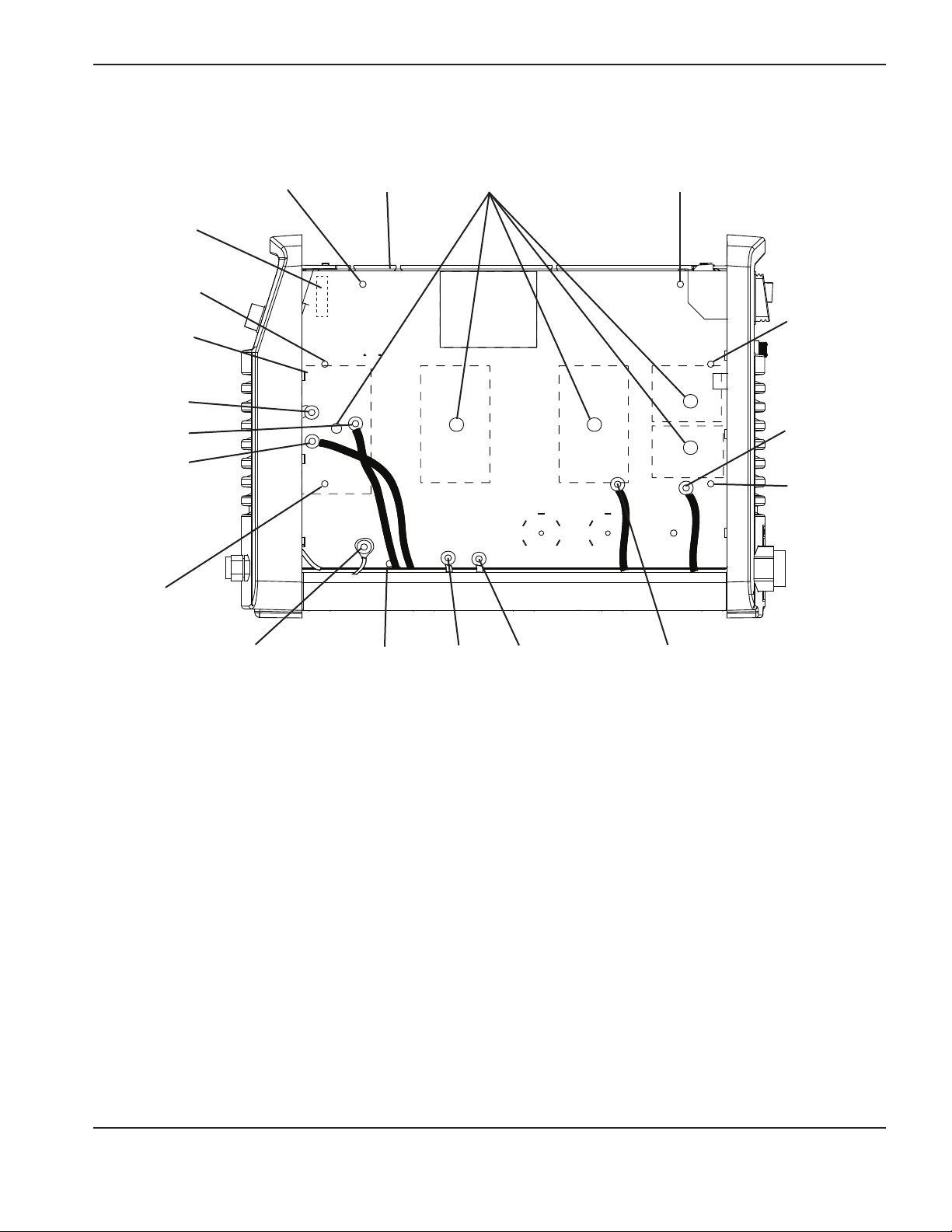
3. Detach the ribbon cable from the heatsink side of the power board. (See the illustration on the following page for
the location of the ribbon cable and the components listed in the next steps.)
4. Remove the torch start and cap sensor connector at J12 on the heatsink side of the power board.
5. Remove the connectors at J4, J5, and J6 on the heatsink side of the power board.
6. Remove the wires for the transformers and inductors at J13, J14, J15, J18, J19, J20, and J21.
7. Remove the work lead ring terminal from J22.
8. Remove the 3 retaining screws and the 4 heatsink assembly screws.
9. Remove the 5 screws that attach the IGBTs to the heatsink. There are holes in the power board to provide access
to them.
3-34 powermax
30
Service Manual
Page 2
Maintenance
Ribbon cable
Heat sink
assembly screw
Torch start and
cap sensor
(J12)
J13
J14
J15
Heat sink
assembly screw
Retaining screw
J4, J5, and J6
IGBT attachment
screws
Retaining screw
Heat sink
assembly
screw
J18
Heat sink
assembly
screw
connector (J22)
Retaining
screw
J21 J20 J19Work lead
powermax
30
Service Manual 3-35
Page 3

Maintenance
10. If you only have 1screw on the snubber resistor, go to 10a (CSAserial number30-009220 and below, CEserial
number30-009289 and below). If you have a spring clip with 2screws on the snubber resistor go to 10b
(CSAserial number30-009221 and above, CEserial number30-009290 and above).
a. Remove the 1screw from the snubber resistor on the top of the heatsink. (CSAserial number30-009220
and below, CEserial number30-009289 and below.)
Snubber
resistor screw
b. Remove the 2screws from the spring clip on the top of the heatsink and remove the spring clip. (CSAserial
number30-009221 and above, CEserial number30-009290 and above.)
Snubber resistor
Snubber
resistor screws
spring clip
11. Detach the bottom 2 wires (both are white) from the ON/OFF switch.
12. Lay the unit on its side (power board down) and use a 5/16-inch (8 mm) nut driver to remove the nuts that secure
the red and the white wires that are routed underneath the board to the studs on the fan side of the unit. The studs
are labeled “RED” and “WHT.”
13. Stand up the unit again. Tuck out of the way all the wires that you detached.
14. Pull the board straight out from the power supply.
15. Before installing a new power board, clean the heatsink with isopropyl alcohol. Gently scrub away any residual
thermal compound, being careful not to scratch the heatsink. Wipe it with a clean cloth.
3-36 powermax
30
Service Manual
Page 4

Maintenance
16. Spread a thin layer of thermal compound 2 mil thick (about the thickness of a sheet of paper) on all the IGBTs.
17. Spread a layer of thermal compound 2 mil thick on the snubber resistor, starting from the bottom and dragging
toward the top (away from the prongs). It is important to avoid getting any compound on the prongs.
18. Push the red and white wires that are attached to the new power board through from the power board side of the
power supply to the fan side of the power supply.
19. Line up the capacitors on the back of the power board with the holes in the power supply’s center panel.
20. Push the power board straight in.
21. Reconnect the 2 white wires to the ON/OFF switch.
22. Replace the 4 heatsink assembly screws and the 3 retaining screws. Torque these screws to 15 inch-pounds
(17.28 kg cm).
23. If you only have 1screw on the snubber resistor, go to 23a (CSAserial number30-009220 and below, CEserial
number30-009289 and below). If you have a spring clip and 2screws on the snubber resistor go to 23b
(CSAserial number30-009221 and above, CEserial number30-009290 and above).
a. Replace the 1screw that you removed from the snubber resistor. Tighten it to 7inch-pounds (8.06 kg-cm).
(CSAserial number30-009220 and below, CEserial number30-009289 and below.)
Note: A torque setting higher than 7inch-pounds (8.06kg-cms) can damage the resistor.
b. Replace the 2screws and spring clip that you removed from the snubber resistor. Tighten the screws to
15inch-pounds (17.28kg-cm). (CSAserial number30-009221 and above, CEserial number30-009290
and above.)
Note: A torque setting higher than 15inch-pounds (17.28kg-cm) can damage the resistor.
24. Replace the 5 screws that attach the IGBTs to the heatsink. The torque setting for these is 15 inch-pounds
(17.28kg cm).
25. Reconnect the wires to the transformers and inductors at J13, J14, J15, J18, J19, J20, and J21 and the work lead
ring terminal at J22. Torque them to 20 inch-pounds (23.04 kg cm).
26. Replace the torch start and cap sensor connector at J12 and the connectors at J4, J5, and J6.
27. Reconnect the ribbon cable from the control board to the power board.
28. Attach the red and white wires to the studs on the fan side of the board.
29. Being careful not to pinch any of the wires, replace the Nomex barrier and slide the cover back onto the power
supply. Make sure that the bottom edges are in the tracks. Position the handle over the holes in the top of the
cover, then use the 2 screws to secure the cover.
30. Reconnect the electrical power and the gas supply.
powermax
30
Service Manual 3-37
 Loading...