

Page 1

®
Powermax125
Plasma Arc Cutting System
Service Manual
808070 | Revision 1 | English
Page 2

Register your new Hypertherm system
Register your product online at www.hypertherm.com/registration for easier technical
and warranty support. You can also receive updates on new Hypertherm products and a free
gift as a token of our appreciation.
For your records
Serial number:________________________________________________________________
Purchase date: _______________________________________________________________
Distributor: __________________________________________________________________
____________________________________________________________________________
____________________________________________________________________________
Maintenance notes:
____________________________________________________________________________
____________________________________________________________________________
____________________________________________________________________________
____________________________________________________________________________
____________________________________________________________________________
____________________________________________________________________________
Powermax, Duramax, Smart Sense, FastConnect, FineCut, and Hypertherm are trademarks of Hypertherm, Inc. and may be registered
in the United States and other countries. All other trademarks are the property of their respective holders.
© 2014 Hypertherm, Inc.
Page 3

Powermax125
Service Manual
808070
Revision 1
English
April 2014
Hypertherm, Inc.
Hanover, NH 03755 USA
Page 4

Hypertherm Inc.
Etna Road, P.O. Box 5010
Hanover, NH 03755 USA
603-643-3441 Tel (Main Office)
603-643-5352 Fax (All Departments)
info@hypertherm.com (Main Office Email)
800-643-9878 Tel (Technical Service)
technical.service@hypertherm.com (Technical Service Email)
800-737-2978 Tel (Customer Service)
customer.service@hypertherm.com (Customer Service Email)
866-643-7711 Tel (Return Materials Authorization)
877-371-2876 Fax (Return Materials Authorization)
return.materials@hypertherm.com (RMA email)
Hypertherm Plasmatechnik GmbH
Technologiepark Hanau
Rodenbacher Chaussee 6
D-63457 Hanau-Wolfgang, Deutschland
49 6181 58 2100 Tel
49 6181 58 2134 Fax
49 6181 58 2123 (Technical Service)
Hypertherm (S) Pte Ltd.
82 Genting Lane
Media Centre
Annexe Block #A01-01
Singapore 349567, Republic of Singapore
65 6841 2489 Tel
65 6841 2490 Fax
65 6841 2489 (Technical Service)
Hypertherm (Shanghai) Trading Co., Ltd.
Unit 301, South Building
495 ShangZhong Road
Shanghai, 200231
PR China
86-21-60740003 Tel
86-21-60740393 Fax
Hypertherm Europe B.V.
Vaartveld 9
4704 SE
Roosendaal, Nederland
31 165 596907 Tel
31 165 596901 Fax
31 165 596908 Tel (Marketing)
31 165 596900 Tel (Technical Service)
00 800 4973 7843 Tel (Technical Service)
Hypertherm Japan Ltd.
Level 9, Edobori Center Building
2-1-1 Edobori, Nishi-ku
Osaka 550-0002 Japan
81 6 6225 1183 Tel
81 6 6225 1184 Fax
Hypertherm Brasil Ltda.
Rua Bras Cubas, 231 – Jardim Maia
Guarulhos, SP - Brasil
CEP 07115-030
55 11 2409 2636 Tel
55 11 2408 0462 Fax
Hypertherm México, S.A. de C.V.
Avenida Toluca No. 444, Anexo 1,
Colonia Olivar de los Padres
Delegación Álvaro Obregón
México, D.F. C.P. 01780
52 55 5681 8109 Tel
52 55 5683 2127 Fax
Hypertherm Korea Branch
#3904 Centum Leaders Mark B/D,
1514 Woo-dong, Haeundae-gu, Busan
Korea, 612-889
82 51 747 0358 Tel
82 51 701 0358 Fax
Page 5

Safety information
Before operating any Hypertherm equipment, read the separate Safety and Compliance Manual (80669C) included
with your product for important safety information.
Page 6

Page 7

Contents
Electromagnetic Compatibility (EMC) ............................................................................ SC-15
Introduction ..............................................................................................................................................................................SC-15
Installation and use .................................................................................................................................................................SC-15
Assessment of area ................................................................................................................................................................SC-15
Methods of reducing emissions ..........................................................................................................................................SC-15
Mains supply ....................................................................................................................................................................SC-15
Maintenance of cutting equipment .....................................................................................................................................SC-16
Cutting cables .........................................................................................................................................................................SC-16
Equipotential bonding ....................................................................................................................................................SC-16
Earthing of the workpiece .............................................................................................................................................SC-16
Screening and shielding .......................................................................................................................................................SC-16
Warranty .................................................................................................................................. SC-17
Attention ....................................................................................................................................................................................SC-17
General .....................................................................................................................................................................................SC-17
Patent indemnity .....................................................................................................................................................................SC-18
Limitation of liability ................................................................................................................................................................SC-18
National and local codes .......................................................................................................................................................SC-18
Liability cap ..............................................................................................................................................................................SC-18
Insurance ..................................................................................................................................................................................SC-18
Transfer of rights .....................................................................................................................................................................SC-18
1 Specifications .............................................................................................................................. 19
Safety information ......................................................................................................................................................................... 19
Powermax125 System description ........................................................................................................................................... 19
Power supply dimensions ........................................................................................................................................................... 20
Component weights (125 A systems) ..................................................................................................................................... 21
Hypertherm power supply ratings ............................................................................................................................................. 22
Powermax125 Service Manual 808070 7
Page 8

Contents
Duramax Hyamp 85° hand torch dimensions ......................................................................................................................... 23
Duramax Hyamp 15° hand torch dimensions ......................................................................................................................... 23
Duramax Hyamp 180° full-length machine torch dimensions ............................................................................................ 24
Duramax Hyamp 180° mini machine torch dimensions ....................................................................................................... 24
Powermax125 cutting specifications ....................................................................................................................................... 25
Symbols and markings ................................................................................................................................................................ 26
Noise levels ............................................................................................................................................................................ 27
IEC symbols ........................................................................................................................................................................... 28
2 Power Supply Setup .................................................................................................................. 29
Unpack the Powermax system .................................................................................................................................................. 29
Claims ...................................................................................................................................................................................... 29
Contents ......................................................................................................................................................................................... 30
Position the power supply .......................................................................................................................................................... 30
Prepare the electrical power ...................................................................................................................................................... 31
Install a line-disconnect switch ......................................................................................................................................... 31
Requirements for grounding .............................................................................................................................................. 31
Power connection for the Powermax125 ............................................................................................................................... 32
Three-phase power cord and plug installation .............................................................................................................. 33
Decrease output current for lower-rated power plugs ........................................................................................ 33
Extension cord recommendations ............................................................................................................................................ 35
Engine-driven generator recommendations ................................................................................................................... 35
Prepare the gas supply ............................................................................................................................................................... 36
Additional gas filtration ........................................................................................................................................................ 36
Connect the gas supply ...................................................................................................................................................... 37
Minimum inlet pressure (while gas is flowing) ........................................................................................................ 38
Gas flow rates ............................................................................................................................................................... 38
3 Basic System Operations ......................................................................................................... 39
Controls and indicators ............................................................................................................................................................... 39
Rear controls ......................................................................................................................................................................... 39
Front controls and LEDs ..................................................................................................................................................... 40
LEDs ................................................................................................................................................................................ 40
Selectors ......................................................................................................................................................................... 40
Operating mode switch ............................................................................................................................................... 41
Amperage adjustment knob ....................................................................................................................................... 41
Status screen ......................................................................................................................................................................... 41
Gas pressure indicators .............................................................................................................................................. 42
System status icons ..................................................................................................................................................... 42
Fault codes and icons .................................................................................................................................................. 42
8 Powermax125 Service Manual 808070
Page 9

Contents
Operating the Powermax ............................................................................................................................................................ 44
Connect the electrical power, gas supply, and torch lead .......................................................................................... 44
Attach the work lead to the power supply ...................................................................................................................... 45
Attach the ground clamp to the workpiece .................................................................................................................... 46
Turn on the system ............................................................................................................................................................... 46
Set the operating mode switch ......................................................................................................................................... 47
Check the indicators ............................................................................................................................................................ 47
Manually adjusting the gas pressure ................................................................................................................................ 48
Adjusting the current (amperage) ..................................................................................................................................... 48
Electrode end-of-life detection feature .................................................................................................................................... 49
Understanding duty-cycle limitations ....................................................................................................................................... 50
4 Hand Torch Setup ....................................................................................................................... 51
Introduction .................................................................................................................................................................................... 51
Consumable life ............................................................................................................................................................................ 51
Hand torch components ............................................................................................................................................................. 52
Duramax Hyamp 85° hand torch ....................................................................................................................................... 52
Duramax Hyamp 15° hand torch ....................................................................................................................................... 52
Choose the hand torch consumables ...................................................................................................................................... 52
Drag-cutting 105/125 A consumables ........................................................................................................................... 53
Drag-cutting 45 A and 65 A consumables ..................................................................................................................... 53
Gouging consumables ........................................................................................................................................................ 53
FineCut consumables .......................................................................................................................................................... 53
Install the hand torch consumables .......................................................................................................................................... 54
Connecting the torch lead .......................................................................................................................................................... 55
5 Hand Cutting ................................................................................................................................ 57
Using the hand torch ................................................................................................................................................................... 57
Operate the safety trigger ........................................................................................................................................................... 58
Hand torch cutting guidelines .................................................................................................................................................... 58
Start a cut from the edge of the workpiece ............................................................................................................................ 59
Pierce a workpiece ....................................................................................................................................................................... 60
Gouge a workpiece ...................................................................................................................................................................... 62
Gouge profile ......................................................................................................................................................................... 63
Varying the gouge profile .................................................................................................................................................... 64
125 A gouging profile chart ............................................................................................................................................... 64
Common hand-cutting faults ..................................................................................................................................................... 66
Powermax125 Service Manual 808070 9
Page 10

Contents
6 Machine Torch Setup ................................................................................................................ 67
Introduction .................................................................................................................................................................................... 67
Consumable life ............................................................................................................................................................................ 67
Machine torch components ....................................................................................................................................................... 68
Duramax Hyamp 180° machine torch .............................................................................................................................. 68
Duramax Hyamp 180° mini machine torch ..................................................................................................................... 68
Disassemble the machine torch ................................................................................................................................................ 69
Convert a full-length machine torch to a mini machine torch ............................................................................................. 71
Mount the torch ............................................................................................................................................................................. 72
Choose the machine torch consumables ............................................................................................................................... 73
Machine torch consumables ...................................................................................................................................................... 73
Mechanized shielded 105 A/125 A consumables ........................................................................................................ 73
Mechanized shielded 45 A and 65 A consumables ..................................................................................................... 73
Mechanized shielded with ohmic 105 A/125 A consumables .................................................................................. 74
Mechanized shielded with ohmic 45 A and 65 A consumables ................................................................................ 74
Gouging consumables ........................................................................................................................................................ 74
FineCut shielded consumables ......................................................................................................................................... 74
FineCut shielded with ohmic consumables .................................................................................................................... 75
Install the machine torch consumables ................................................................................................................................... 75
Aligning the torch ......................................................................................................................................................................... 75
Connecting the torch lead .......................................................................................................................................................... 76
Using the cut charts ..................................................................................................................................................................... 77
Estimated kerf-width compensation ................................................................................................................................. 78
Estimated kerf-width compensation – Metric (mm) .............................................................................................. 78
Estimated kerf-width compensation – English (inches) ...................................................................................... 79
125 A shielded consumables ............................................................................................................................................ 80
125 A shielded cutting – mild steel ................................................................................................................................. 81
125 A shielded cutting – stainless steel ......................................................................................................................... 82
125 A shielded cutting – aluminum ................................................................................................................................. 83
105 A shielded consumables ............................................................................................................................................ 84
105 A shielded cutting – mild steel ................................................................................................................................. 85
105 A shielded cutting – stainless steel ......................................................................................................................... 86
105 A shielded cutting – aluminum ................................................................................................................................. 87
65 A shielded consumables ............................................................................................................................................... 88
65 A shielded cutting – mild steel .................................................................................................................................... 89
65 A shielded cutting – stainless steel ........................................................................................................................... 90
65 A shielded cutting – aluminum .................................................................................................................................... 91
45 A shielded consumables ............................................................................................................................................... 92
45 A shielded cutting – mild steel .................................................................................................................................... 93
45 A shielded cutting – stainless steel ........................................................................................................................... 94
45 A shielded cutting – aluminum .................................................................................................................................... 95
10 Powermax125 Service Manual 808070
Page 11

Contents
FineCut consumables .......................................................................................................................................................... 96
FineCut – mild steel ............................................................................................................................................................. 97
FineCut – stainless steel ..................................................................................................................................................... 98
7 Mechanized Cutting ................................................................................................................... 99
Connecting an optional remote-start pendant ....................................................................................................................... 99
Connecting the machine interface cable .............................................................................................................................. 100
Machine interface pinout ................................................................................................................................................... 102
Setting the five-position voltage divider ........................................................................................................................ 103
Accessing raw arc voltage ....................................................................................................................................................... 104
Connecting an optional RS-485 serial interface cable ..................................................................................................... 104
Serial port cables ................................................................................................................................................................ 105
Using the machine torch ........................................................................................................................................................... 105
Setting up the torch and table ................................................................................................................................................. 105
Understand and optimize cut quality ...................................................................................................................................... 105
Cut or bevel angle .............................................................................................................................................................. 106
Dross ..................................................................................................................................................................................... 106
Piercing a workpiece using the machine torch .................................................................................................................... 107
Common machine-cutting faults ............................................................................................................................................. 107
8 Troubleshooting and System Tests ..................................................................................... 109
Controls and indicators ............................................................................................................................................................. 109
Rear panel ............................................................................................................................................................................ 109
Front panel ............................................................................................................................................................................ 110
Status screen ............................................................................................................................................................... 110
Theory of operation .................................................................................................................................................................... 111
480 V and 600 V CSA 3-phase power supply functional description .................................................................. 111
400 V CE, 380 V CCC 3-phase power supply functional description ................................................................. 111
Sequence of operation ...................................................................................................................................................... 112
Troubleshooting preparation .................................................................................................................................................... 113
Test equipment .................................................................................................................................................................... 113
Troubleshooting procedures and sequence ................................................................................................................. 113
External inspection .............................................................................................................................................................. 115
Internal inspection ............................................................................................................................................................... 115
Initial resistance check .............................................................................................................................................................. 115
Check the power switch ................................................................................................................................................... 115
Hypertherm IGBT tester .................................................................................................................................................... 118
Indicator LEDs and device tests ..................................................................................................................................... 119
IGBT test preparation ........................................................................................................................................................ 119
IGBT device test using the Hypertherm tester ............................................................................................................ 121
Troubleshoot the Hypertherm IGBT tester ................................................................................................................... 121
Powermax125 Service Manual 808070 11
Page 12

Contents
IGBT device test using a non-Hypertherm tester ............................................................................................................... 122
Fault codes ................................................................................................................................................................................... 128
Important fault icons ........................................................................................................................................................... 128
Displaying the service screen .......................................................................................................................................... 128
Run a gas test ..................................................................................................................................................................... 130
Perform a cold restart ........................................................................................................................................................ 131
Fault codes and solutions ................................................................................................................................................. 131
Fault code format – 0-00-0 ...................................................................................................................................... 131
Fault code format – 0-nn-n ...................................................................................................................................... 132
Fault code format – 1-nn-n ...................................................................................................................................... 138
Fault code format – 2-nn-n ...................................................................................................................................... 138
Fault code format – 3-nn-n ...................................................................................................................................... 139
Torch-related faults – continuity check ................................................................................................................. 142
Troubleshooting guide ............................................................................................................................................................... 143
System tests ................................................................................................................................................................................ 149
Test 1 – Voltage input ....................................................................................................................................................... 150
Test 2 – DC power bus .................................................................................................................................................... 152
Resistance check ........................................................................................................................................................ 152
Voltage check .............................................................................................................................................................. 152
Test 3 – Output diodes ..................................................................................................................................................... 154
Test 4 – Inverter temperature sensor ............................................................................................................................. 154
For operational fault codes 0-40-2 and 0-40-3 or power board faults 2-10-0 and 2-10-1 ................... 155
Test 5 – Flyback circuit (DC minor voltages) ............................................................................................................... 156
Test 6 – Torch stuck open/torch stuck closed ............................................................................................................ 158
Test 7 – Start signal ........................................................................................................................................................... 160
Test 8 – Torch cap switch ................................................................................................................................................ 161
Test 9 – Electronic regulator ........................................................................................................................................... 162
Test 10 – Pressure sensor ............................................................................................................................................... 163
Test 11 – Fan ...................................................................................................................................................................... 164
Test 12 – AUX switch ....................................................................................................................................................... 164
9 Power Supply Component Replacement ........................................................................... 165
Installing a machine interface cable for raw arc voltage .................................................................................................... 166
Disconnect the power and gas supply .................................................................................................................................. 166
Replacing the gas filter element .............................................................................................................................................. 167
Replacing the work lead connector ....................................................................................................................................... 169
Installing the optional filter kit .................................................................................................................................................. 170
Replacing the power supply cover ......................................................................................................................................... 172
Replacing the component barrier ........................................................................................................................................... 173
Replacing the end panel bracket ............................................................................................................................................ 174
12 Powermax125 Service Manual 808070
Page 13

Contents
Replacing the machine interface cable with voltage divider board ................................................................................. 176
Set the voltage divider board ........................................................................................................................................... 181
Installing the machine interface cable .................................................................................................................................... 182
Installing the RS-485 serial interface cable ......................................................................................................................... 183
Replacing the power cord and strain relief ........................................................................................................................... 190
Replacing the power switch ..................................................................................................................................................... 197
Replacing the control board ..................................................................................................................................................... 201
Replacing the DSP board ......................................................................................................................................................... 203
Replacing the power board ...................................................................................................................................................... 205
Replacing the input diode bridge ............................................................................................................................................ 209
Replacing the output diode bridge ......................................................................................................................................... 210
Replacing the pilot arc IGBT ................................................................................................................................................... 211
Replacing the inverter IGBT module ...................................................................................................................................... 212
Replacing the snubber resistor ............................................................................................................................................... 213
Replacing the thermal sensor .................................................................................................................................................. 214
Replacing the fan shroud .......................................................................................................................................................... 216
Replacing the fan ........................................................................................................................................................................ 217
Replacing the pressure transducer ........................................................................................................................................ 219
Replacing the pressure switch ................................................................................................................................................ 221
Replacing the gas filter assembly ........................................................................................................................................... 223
Replacing the solenoid valve ................................................................................................................................................... 225
Replacing the gas tubing .......................................................................................................................................................... 227
Replacing the bulk capacitors ................................................................................................................................................. 229
Replacing the torch quick disconnect receptacle .............................................................................................................. 231
Replacing the work lead receptacle ....................................................................................................................................... 236
Replacing the output inductor ................................................................................................................................................. 238
Replacing the transformer ........................................................................................................................................................ 244
Replacing the PFC inductor ..................................................................................................................................................... 249
Replacing the front panel .......................................................................................................................................................... 252
Replacing the rear panel ........................................................................................................................................................... 257
10 Torch Component Replacement .......................................................................................... 265
Disconnect the power, gas supply, and torch ..................................................................................................................... 266
Hand torches ............................................................................................................................................................................... 267
Replacing the handle ......................................................................................................................................................... 269
Replacing the trigger assembly ....................................................................................................................................... 274
Replacing the torch body .................................................................................................................................................. 276
Replacing the start switch ................................................................................................................................................ 278
Replacing the cap-sensor switch ................................................................................................................................... 280
Replacing the torch lead ................................................................................................................................................... 281
Powermax125 Service Manual 808070 13
Page 14

Contents
Machine torches ......................................................................................................................................................................... 284
Replacing the mounting sleeve ....................................................................................................................................... 285
Replacing the cap sensor switch .................................................................................................................................... 287
Replacing the torch body .................................................................................................................................................. 288
Replacing the coupler and positioning sleeve (full-length only) or adapter (mini only) ...................................... 289
Replacing the torch lead ................................................................................................................................................... 290
Replacing the quick disconnect housing .............................................................................................................................. 291
11 Parts ............................................................................................................................................. 293
Power supply parts .................................................................................................................................................................... 294
Exterior, front ........................................................................................................................................................................ 294
Exterior, rear ......................................................................................................................................................................... 295
Interior, power board side ................................................................................................................................................. 297
480 V, 600 V CSA ..................................................................................................................................................... 297
400 V CE/380 V CCC .............................................................................................................................................. 298
Interior, fan side ................................................................................................................................................................... 299
Interior, heatsink assembly ................................................................................................................................................ 300
Duramax Hyamp 85° hand torch replacement parts .......................................................................................................... 301
Duramax Hyamp 15° hand torch replacement parts .......................................................................................................... 302
Hand torch consumables .......................................................................................................................................................... 303
Drag cutting ......................................................................................................................................................................... 303
Gouging ................................................................................................................................................................................ 303
FineCut .................................................................................................................................................................................. 303
Duramax Hyamp 180° full-length machine torch replacement parts .............................................................................. 304
Duramax Hyamp 180° mini machine torch replacement parts ......................................................................................... 305
Machine torch consumables .................................................................................................................................................... 306
Shielded ................................................................................................................................................................................ 306
Gouging ................................................................................................................................................................................ 306
FineCut .................................................................................................................................................................................. 307
Accessory parts .......................................................................................................................................................................... 307
Powermax125 labels ................................................................................................................................................................. 308
Safety-critical parts .................................................................................................................................................................... 310
Power supply, power board side .................................................................................................................................... 310
Power supply, fan side ...................................................................................................................................................... 312
Recommended spare parts ...................................................................................................................................................... 313
12 Wiring Diagrams ....................................................................................................................... 315
Powermax generic timing chart ............................................................................................................................................... 316
Powermax125 schematic diagram ......................................................................................................................................... 317
14 Powermax125 Service Manual 808070
Page 15

Electromagnetic Compatibility (EMC)
Introduction
Hypertherm’s CE-marked equipment is built in compliance
with standard EN60974-10. The equipment should be
installed and used in accordance with the information
below to achieve electromagnetic compatibility.
The limits required by EN60974-10 may not be adequate
to completely eliminate interference when the affected
equipment is in close proximity or has a high degree of
sensitivity. In such cases it may be necessary to use other
measures to further reduce interference.
This cutting equipment is designed for use only in an
industrial environment.
Installation and use
The user is responsible for installing and using the plasma
equipment according to the manufacturer’s instructions.
If electromagnetic disturbances are detected then it shall
be the responsibility of the user to resolve the situation
with the technical assistance of the manufacturer. In some
cases this remedial action may be as simple as earthing
the cutting circuit, see Earthing of the work piece. In other
cases, it could involve constructing an electromagnetic
screen enclosing the power source and the work
complete with associated input filters. In all cases,
electromagnetic disturbances must be reduced to the
point where they are no longer troublesome.
Assessment of area
Before installing the equipment, the user shall make an
assessment of potential electromagnetic problems in the
surrounding area. The following shall be taken into
account:
a. Other supply cables, control cables, signaling
and telephone cables; above, below and adjacent
to the cutting equipment.
b. Radio and television transmitters and receivers.
c. Computer and other control equipment.
d. Safety critical equipment, for example guarding of
industrial equipment.
e. Health of the people around, for example the use
of pacemakers and hearing aids.
f. Equipment used for calibration or measurement.
g. Immunity of other equipment in the environment.
User shall ensure that other equipment being
used in the environment is compatible. This may
require additional protection measures.
h. Time of day that cutting or other activities are to
be carried out.
The size of the surrounding area to be considered will
depend on the structure of the building and other activities
that are taking place. The surrounding area may extend
beyond the boundaries of the premises.
Methods of reducing emissions
Mains supply
Cutting equipment must be connected to the mains
supply according to the manufacturer’s recommendations.
If interference occurs, it may be necessary to take
additional precautions such as filtering of the mains
supply.
Consideration should be given to shielding the supply
cable of permanently installed cutting equipment, in
metallic conduit or equivalent. Shielding should be
electrically continuous throughout its length. The shielding
should be connected to the cutting mains supply so that
good electrical contact is maintained between the conduit
and the cutting power source enclosure.
Safety and Compliance SC-15
Page 16

Electromagnetic Compatibility (EMC)
Maintenance of cutting equipment
The cutting equipment must be routinely maintained
according to the manufacturer’s recommendations. All
access and service doors and covers should be closed
and properly fastened when the cutting equipment is in
operation. The cutting equipment should not be modified
in any way, except as set forth in and in accordance with
the manufacturer’s written instructions. For example, the
spark gaps of arc striking and stabilizing devices should
be adjusted and maintained according to the
manufacturer’s recommendations.
Cutting cables
The cutting cables should be kept as short as possible
and should be positioned close together, running at or
close to the floor level.
Equipotential bonding
Bonding of all metallic components in the cutting
installation and adjacent to it should be considered.
Earthing of the workpiece
Where the workpiece is not bonded to earth for electrical
safety, nor connected to earth because of its size and
position, for example, ship’s hull or building steel work, a
connection bonding the workpiece to earth may reduce
emissions in some, but not all instances. Care should be
taken to prevent the earthing of the workpiece increasing
the risk of injury to users, or damage to other electrical
equipment. Where necessary, the connection of the
workpiece to earth should be made by a direct connection
to the workpiece, but in some countries where direct
connection is not permitted, the bonding should be
achieved by suitable capacitances selected according to
national regulations.
Note: The cutting circuit may or may not be earthed for
safety reasons. Changing the earthing arrangements
should only be authorized by a person who is competent
to assess whether the changes will in crease the risk of
injury, for example, by allowing parallel cutting current
return paths which may damage the earth circuits of other
equipment. Further guidance is provided in IEC 60974-9,
Arc Welding Equipment, Part 9: Installation and Use.
However, metallic components bonded to the workpiece
will increase the risk that the operator could receive a
shock by touching these metallic components and the
electrode (nozzle for laser heads) at the same time.
The operator should be insulated from all such bonded
metallic components.
Screening and shielding
Selective screening and shielding of other cables and
equipment in the surrounding area may alleviate problems
of interference. Screening of the entire plasma cutting
installation may be considered for special applications.
SC-16 Safety and Compliance
Page 17

Warranty
Attention
Genuine Hypertherm parts are the factory-recommended
replacement parts for your Hypertherm system. Any
damage or injury caused by the use of other than genuine
Hypertherm parts may not be covered by the Hypertherm
warranty, and will constitute misuse of the Hypertherm
Product.
You are solely responsible for the safe use of the Product.
Hypertherm does not and cannot make any guarantee or
warranty regarding the safe use of the product in your
environment.
General
Hypertherm, Inc. warrants that its Products shall be free
from defects in materials and workmanship for the specific
periods of time set forth herein and as follows: if
Hypertherm is notified of a defect (i) with respect to the
plasma power supply within a period of two (2) years from
the date of its delivery to you, with the exception of
Powermax brand power supplies, which shall be within a
period of three (3) years from the date of delivery to you,
and (ii) with respect to the torch and leads within a period
of one (1) year from its date of delivery to you, and with
respect to torch lifter assemblies within a period of one (1)
year from its date of delivery to you, and with respect to
Automation products one (1) year from its date of delivery
to you, with the exception of the EDGE Pro CNC,
EDGE Pro Ti CNC, MicroEDGE Pro CNC, and
ArcGlide THC, which shall be within a period of two (2)
years from the date of delivery to you, and (iii) with respect
to HyIntensity fiber laser components within a period of
two (2) years from the date of its delivery to you, with the
exception of laser heads and beam delivery cables, which
shall be within a period of one (1) year from its date of
delivery to you.
Hypertherm provides repair, replacement or adjustment of
the Product as the sole and exclusive remedy, if and only if
the warranty set forth herein properly is invoked and
applies. Hypertherm, at its sole option, shall repair,
replace, or adjust, free of charge, any defective Products
covered by this warranty which shall be returned with
Hypertherm’s prior authorization (which shall not be
unreasonably withheld), properly packed, to Hypertherm’s
place of business in Hanover, New Hampshire, or to an
authorized Hypertherm repair facility, all costs, insurance
and freight pre paid by the customer. Hypertherm shall not
be liable for any repairs, replacement, or adjustments of
Products covered by this warranty, except those made
pursuant to this paragraph and with Hypertherm’s prior
written consent.
The warranty set forth above is exclusive and is in lieu of all
other warranties, express, implied, statutory, or otherwise
with respect to the Products or as to the results which
may be obtained therefrom, and all implied warranties or
conditions of quality or of merchantability or fitness for a
particular purpose or against infringement. The foregoing
shall constitute the sole and exclusive remedy for any
breach by Hypertherm of its warranty.
Distributors/OEMs may offer different or additional
warranties, but Distributors/OEMs are not authorized to
give any additional warranty protection to you or make any
representation to you purporting to be binding upon
Hypertherm.
This warranty shall not apply to any Powermax brand
power supplies that have been used with phase
converters. In addition, Hypertherm does not warranty
systems that have been damaged as a result of poor
power quality, whether from phase converters or incoming
line power. This warranty shall not apply to any product
which has been incorrectly installed, modified, or
otherwise damaged.
Safety and Compliance SC-17
Page 18

Warranty
Patent indemnity
Except only in cases of products not manufactured by
Hypertherm or manufactured by a person other than
Hypertherm not in strict conformity with Hypertherm’s
specifications and in cases of designs, processes,
formulae, or combinations not developed or purported to
be developed by Hypertherm, Hypertherm will have the
right to defend or settle, at its own expense, any suit or
proceeding brought against you alleging that the use of
the Hypertherm product, alone and not in combination
with any other product not supplied by Hypertherm,
infringes any patent of any third party. You shall notify
Hypertherm promptly upon learning of any action or
threatened action in connection with any such alleged
infringement (and in any event no longer than fourteen
(14) days after learning of any action or threat of action),
and Hypertherm’s obligation to defend shall be
conditioned upon Hypertherm’s sole control of, and the
indemnified party’s cooperation and assistance in, the
defense of the claim.
Limitation of liability
In no event shall Hypertherm be liable to any
person or entity for any incidental, consequential
direct, indirect, punitive or exemplary damages
(including but not limited to lost profits) regardless
of whether such liability is based on breach of
contract, tort, strict liability, breach of warranty,
failure of essential purpose, or otherwise, and even
if advised of the possibility of such damages.
National and local codes
Liability cap
In no event shall Hypertherm’s liability, if any,
whether such liability is based on breach of
contract, tort, strict liability, breach of warranties,
failure of essential purpose or otherwise, for any
claim, action, suit or proceeding (whether in court,
arbitration, regulatory proceeding or otherwise)
arising out of or relating to the use of the Products
exceed in the aggregate the amount paid for the
Products that gave rise to such claim.
Insurance
At all times you will have and maintain insurance in such
quantities and types, and with coverage sufficient and
appropriate to defend and to hold Hypertherm harmless in
the event of any cause of action arising from the use of the
products.
Transfer of rights
You may transfer any remaining rights you may have
hereunder only in connection with the sale of all or
substantially all of your assets or capital stock to a
successor in interest who agrees to be bound by all of the
terms and conditions of this Warranty. Within thirty (30)
days before any such transfer occurs, you agree to notify
in writing Hypertherm, which reserves the right of
approval. Should you fail timely to notify Hypertherm and
seek its approval as set forth herein, the Warranty set forth
herein shall be null and void and you will have no further
recourse against Hypertherm under the Warranty or
otherwise.
National and local codes governing plumbing and
electrical installation shall take precedence over any
instructions contained in this manual. In no event shall
Hypertherm be liable for injury to persons or property
damage by reason of any code violation or poor work
practices.
SC-18 Safety and Compliance
Page 19

Section 1
Specifications
Safety information
Before operating any Hypertherm equipment, read the separate Safety and Compliance Manual (80669C) included with
your product for important safety information.
Powermax125 System description
The Powermax125 is a highly portable, 125 A, handheld and mechanized plasma cutting system appropriate for a wide
range of applications. The Powermax system uses air or nitrogen to cut electrically conductive metals, such as mild steel,
stainless steel, or aluminum. Smart Sense™ technology automatically adjusts the gas pressure according to cutting mode
and torch lead length for optimum cutting.
The Powermax125 is recommended for metal thicknesses up to 44 mm (1-3/4 inches), can sever up to 57 mm
(2-1/4 inches), and can pierce thicknesses up to 25 mm (1 inch). FastConnect™ provides a simple push-button torch
connection to the power supply for quick torch changes.
The typical handheld Powermax125 system includes a Duramax™ Hyamp 85° hand torch with a starter consumable kit, a
box of spare electrodes and nozzles, and a work lead cable. Reference materials include: operator manual, quick setup
card, registration card, setup DVD, and safety manual.
The typical mechanized Powermax125 system includes a Duramax Hyamp 180° full-length machine torch with a starter
consumable kit, a box of spare electrodes and nozzles, work lead cable, and remote-start pendant. Reference materials
include: operator manual, quick setup card, registration card, setup DVD, and safety manual.
See your Hypertherm distributor for other system configurations. You can order additional styles of torches, consumables,
and accessories, such as the plasma cutting guide. See Parts on page 293 for a list of spare and optional parts.
Powermax125 CSA and CE power supplies ship without a plug on the power cord. See Power Supply Setup on
page 29.
CCC certified configurations do not ship with a power cord.
Powermax125 Service Manual 808070 19
Page 20
1 – Specifications
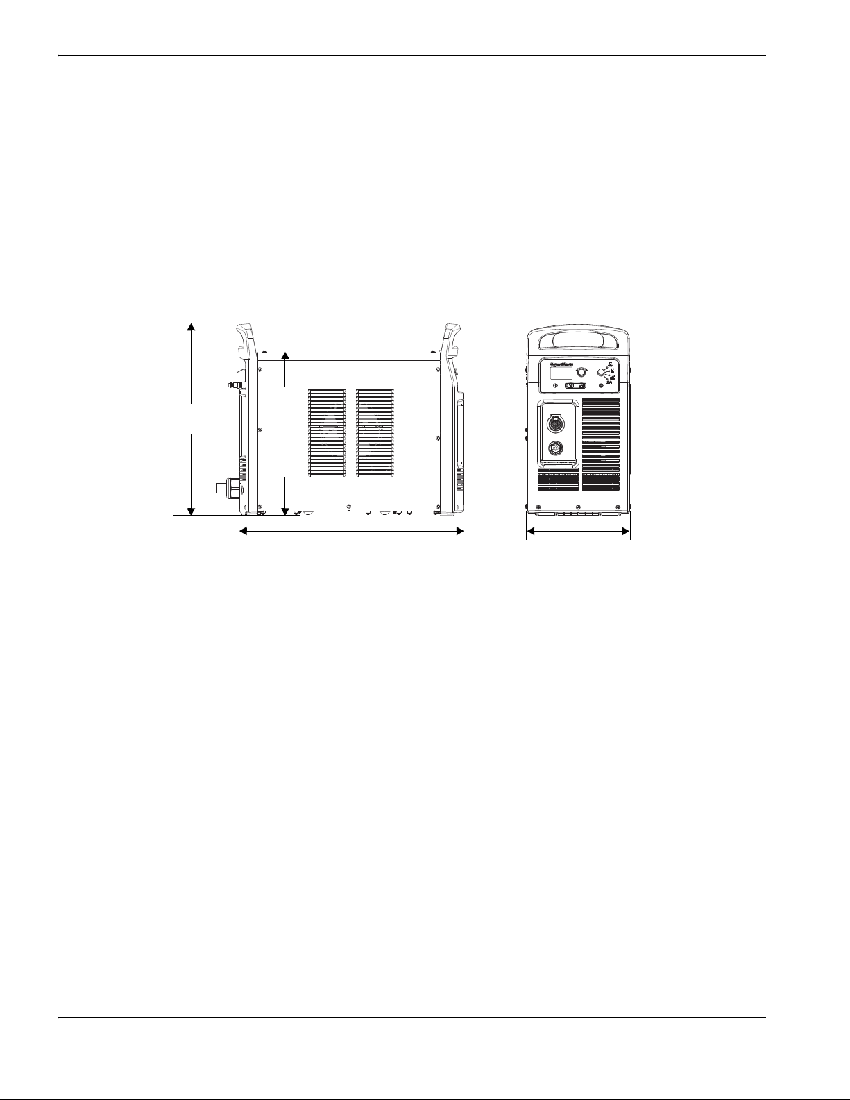
508 mm
(20.0 inches)
592 mm
(23.3 inches)
274 mm
(10.8 inches)
432 mm (17.0 inches)
Powermax125 3-phase systems include the following models:
480 V CSA (480 V only)
600 V CSA (600 V only)
400 V CE (400 V only)
380 V CCC (380 V only)
To maintain CE certification, install power cord kit 228886.
Power supply dimensions
20 Powermax125 Service Manual 808070
Page 21

Component weights (125 A systems)
Table 1 – Power supply weights
1 – Specifications
Voltage 480 V CSA 600 V CSA 400 V CE
Power supply 41 kg
(90 pounds)
With 7.6 m (25 foot) hand
torch and 7.6 m (25 foot)
work lead
48 kg
(106 pounds)
40 kg
(89 pounds)
48 kg
(105 pounds)
42 kg
(92 pounds)
49 kg
(108 pounds)
Table 2 – Torch weights
Hand torch 7.6 m (25 feet) 3.5 kg (7.7 pounds)
Hand torch 15 m (50 feet) 6.2 kg (13.7 pounds)
Hand torch 23 m (75 feet) 8.8 kg (19.5 pounds)
Machine torch 7.6 m (25 feet) 3.7 kg (8.2 pounds)
Machine torch 11 m (35 feet) 4.8 kg (10.6 pounds)
Machine torch 15 m (50 feet) 6.4 kg (14.2 pounds)
380 V CCC
(no power cord)
38 kg
(84 pounds)
45 kg
(100 pounds)
Machine torch 23 m (75 feet) 9.2 kg (20.3 pounds)
Table 3 – Work lead weights
Work lead 7.6 m (25 feet) 3.6 kg (8 pounds)
Work lead 15 m (50 feet) 6.6 kg (14.6 pounds)
Work lead 23 m (75 feet) 9.6 kg (21.2 pounds)
Powermax125 Service Manual 808070 21
Page 22

1 – Specifications
Hypertherm power supply ratings
Rated open-circuit voltage (U0)480/600V CSA
400 V CE
380 V CCC
Output characteristic
Rated output current (I
Rated output voltage (U
1
) 30 – 125 A
2
)175VDC
2
Duty cycle at 40° C (104° F) 480/600 V CSA
400 V CE
380 VCCC
320 VDC
305 VDC
290 VDC
Drooping
100% at 125 A, 480/600 V, 3-PH
100% at 125 A, 400 V, 3-PH
100% at 125 A, 380 V, 3-PH
Operating temperature -10° to 40° C (14° to 104° F)
Storage temperature -25° to 55° C (-13° to 131° F)
Power factor 0.94
– Short Circuit Ratio (CE models
R
sce
only)
EMC emissions classification
CISPR 11 (CE models only)
Input voltage (U
rated output (U
)/ Input current (I1) at
1
2 MAX I2 MAX
2
)
U1 – Volts AC rms, 3-PH R
400 V CE 250
Class A
480/600 V CSA 480/600 V, 3-PH, 50/60 Hz, 31/24 A
400 V CE
3,4
400V, 3-PH, 50/60Hz, 36A
sce
(See Power Supply Setup on
page 29.)
380 V CC 380 V, 3-PH, 50/60 Hz, 38 A
Gas type Air Nitrogen
Gas quality Clean, dry, oil-free per ISO 8573-1
99.95% pure
Class 1.2.2
Recommended gas inlet flow
rate/pressure
Cutting: 260 slpm (550 scfh, 9.2 scfm) at:
• 5.9 bar (85 psi) for 7.6 m (25 foot) and 15 m (50 foot) torches
• 6.6 bar (95 psi) for 23 m (75 foot) torches
Gouging: 212 slpm (450 scfh, 7.5 scfm) at 4.1 bar (60 psi)
1
Defined as a plot of output voltage versus output current.
2
This Class A equipment is not intended for use in residential locations where the electrical power is provided by the public
low-voltage supply system. There may be potential difficulties in ensuring electromagnetic compatibility in those locations due to
conducted or radiated disturbances.
3
This product meets the technical requirements of IEC 61000-3-3 and is not subject to conditional connection.
4
Equipment complies with IEC 61000-3-12 provided that the short-circuit power Ssc is greater than or equal to 5363 KVA at the
interface point between the user’s supply and the public system. It is the responsibility of the installer or user of the equipment to
ensure, by consultation with the distribution network operator if necessary, that the equipment is connected only to a supply with
a short-circuit power S
greater than or equal to 5363 KVA.
sc
22 Powermax125 Service Manual 808070
Page 23
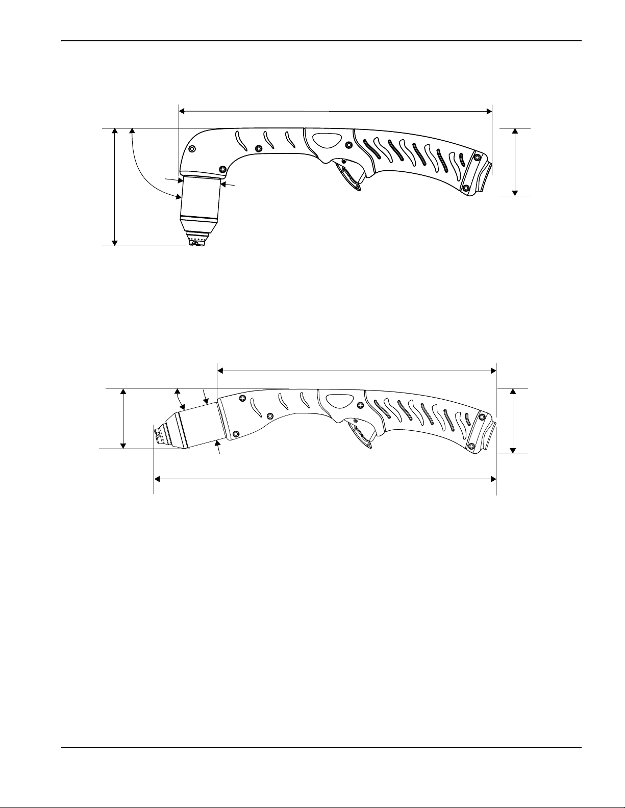
Duramax Hyamp 85° hand torch dimensions
31.2 cm (12.3 inches)
3.5 cm
(1.375 inch)
11.4 cm
(4.5 inches)
85°
6.8 cm
(2.68 inches)
29.5 cm (11.6 inches)
6.8 cm
(2.68 inches)
5.85 cm
(2.3 inches)
15°
3.5 cm (1.375 inch)
35.3 cm (13.9 inches)
Duramax Hyamp 15° hand torch dimensions
1 – Specifications
Powermax125 Service Manual 808070 23
Page 24
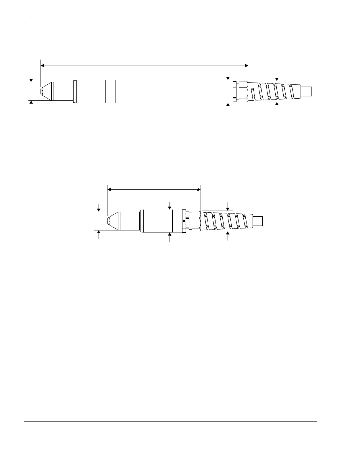
1 – Specifications
3.5 cm (1.375 inches)
40.6 cm (16.0 inches)
4.4 cm (1.75 inches)
4.2 cm (1.6 inch) outer dimension,
3.6 cm (1.4 inch) flat sides
3.5 cm (1.375 inch)
18.3 cm (7.2 inches)
4.4 cm (1.75 inches)
4.2 cm (1.6 inch) outer dimension,
3.6 cm (1.4 inch) flat sides
Duramax Hyamp 180° full-length machine torch dimensions
Duramax Hyamp 180° mini machine torch dimensions
24 Powermax125 Service Manual 808070
Page 25

Powermax125 cutting specifications
Handheld cut capacity (material thickness)
1 – Specifications
Recommended cut capacity at 457 mm/min (18 ipm)
Recommended cut capacity at 250 mm/min (10 ipm)
Severance capacity at 125 mm/min (5 ipm)
1
1
1
38 mm (1-1/2 inches)
44 mm (1-3/4 inches)
57 mm (2-1/4 inches)
Pierce capacity (material thickness)
Pierce capacity for handheld cutting, or mechanized cutting with
25 mm (1 inch)
programmable torch height control
Pierce capacity for mechanized cutting without programmable torch height
22 mm (7/8 inch)
control
Maximum cut speed2 (mild steel)
6mm (1/4inch) 7160 mm/min (282 ipm)
10 mm (3/8 inch) 4390 mm/min (173 ipm)
12 mm (1/2 inch) 2950 mm/min (116 ipm)
16 mm (5/8 inch) 2110 mm/min (83 ipm)
20 mm (3/4 inch) 1470 mm/min (58 ipm)
22 mm (7/8 inch) 1170 mm/min (46 ipm)
25 mm (1 inch) 940 mm/min (37 ipm)
32 mm (1-1/4 inches) 610 mm/min (24 ipm)
38 mm (1-1/2 inches) 457 mm/min (18 ipm)
Gouging capacity
Metal removal rate on mild steel (125 A) 12.5 kg/hour (27 pounds/hour)
Duramax Hyamp series torch weights (refer to Component weights (125 A systems) on page 21)
Duty cycle and voltage information (refer to Hypertherm power supply ratings on page 22)
1
Cut capacity speeds are not necessarily maximum speeds. They are the speeds that must be achieved to be rated at that
thickness.
2
Maximum cut speeds are the results of Hypertherm’s laboratory testing. Actual cutting speeds may vary based on different cutting
applications.
Powermax125 Service Manual 808070 25
Page 26

1 – Specifications
s
Symbols and markings
Your Hypertherm product may have one or more of the following markings on or near the data plate. Due to differences
and conflicts in national regulations, not all marks are applied to every version of a product.
S mark
The S mark indicates that the power supply and torch are suitable for operations carried out in
environments with increased hazard of electrical shock according to IEC 60974-1.
CSA mark
Hypertherm products with a CSA mark meet the United States and Canadian regulations for product
safety. The products were evaluated, tested, and certified by CSA-International. Alternatively, the product
may have a mark by one of the other Nationally Recognized Testing Laboratories (NRTL) accredited in
both the United States and Canada, such as Underwriters Laboratories, Incorporated (UL) or TÜV.
CE mark
The CE marking signifies the manufacturer’s declaration of conformity to applicable European directives
and standards. Only those versions of Hypertherm products with a CE marking located on or near the
data plate have been tested for compliance with the European Low Voltage Directive and the European
Electromagnetic Compatibility (EMC) Directive. EMC filters needed to comply with the European
EMC Directive are incorporated within versions of the product with a CE marking.
Eurasian Customs Union (CU) mark
CE versions of Hypertherm products that include an EAC mark of conformity meet the product safety and
EMC requirements for export to Russia, Belarus, and Kazakhstan.
GOST-TR mark
CE versions of Hypertherm products that include a GOST-TR mark of conformity meet the product safety
and EMC requirements for export to the Russian Federation.
C-Tick mark
CE versions of Hypertherm products with a C-Tick mark comply with the EMC regulations required for
sale in Australia and New Zealand.
CCC mark
The China Compulsory Certification (CCC) mark indicates that the product has been tested and found
compliant with product safety regulations required for sale in China.
UkrSEPRO mark
The CE versions of Hypertherm products that include a UkrSEPRO mark of conformity meet the product
safety and EMC requirements for export to the Ukraine.
Serbian AAA mark
CE versions of Hypertherm products that include a AAA Serbian mark meet the product safety and EMC
requirements for export to Serbia.
26 Powermax125 Service Manual 808070
Page 27

1 – Specifications
Noise levels
This plasma system may exceed acceptable noise levels as defined by national and local codes. Always wear proper ear
protection when cutting or gouging. Any noise measurements taken depend on the specific environment in which the
system is used. Refer to Noise can damage hearing in the Safety and Compliance Manual (80669C) included with your
system.
In addition, you can find an Acoustical Noise Data Sheet for your system in the Hypertherm downloads library at
https://www.hypertherm.com
1. Click “Downloads library.”
2. Select a product from the “Product type” menu.
3. Select “Regulatory” from the “Category” menu.
4. Select “Acoustical Noise Data Sheets” from the “Sub Category” menu.
:
Powermax125 Service Manual 808070 27
Page 28
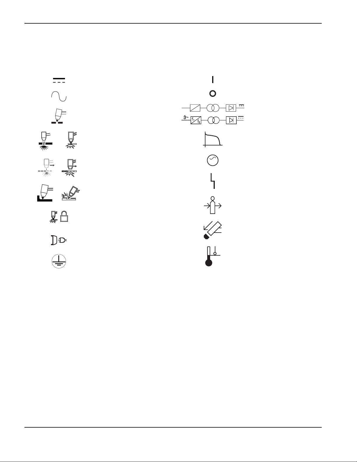
1 – Specifications
Direct current (DC)
Alternating current (AC)
Plasma torch cutting
Plate metal cutting
Expanded metal cutting
Gouging
Torc h l ock
AC input power connection
The terminal for the external
protective (earth) conductor
Power is ON
Power is OFF
An inverter-based power
source, either 1-phase or
3-phase
Volt/amperage curve,
“drooping” characteristic
Power is ON (LED)
System fault (LED)
Inlet gas pressure fault (LCD)
Missing or loose
consumables (LCD)
Power supply is out of
temperature range (LCD)
f
1
f
2
1~
AC
AC
IEC symbols
The following symbols may appear on the power supply data plate, control labels, switches, LEDs, and LCD screen.
28 Powermax125 Service Manual 808070
Page 29

Section 2
Power Supply Setup
Unpack the Powermax system
1. Verify that all items on your order have been received in good condition. Contact your distributor if any parts are
damaged or missing.
2. Inspect the power supply for damage that may have occurred during shipping. If there is evidence of damage, refer to
Claims. All communications regarding this equipment must include the model number and the serial number located
on the back of the power supply.
3. Before you set up and operate this Hypertherm system, read the separate Safety and Compliance Manual (80669C)
included with your system for important safety information.
Claims
Claims for damage during shipment – If your unit was damaged during shipment, you must file a claim with the
carrier. Hypertherm will furnish you with a copy of the bill of lading upon request. If you need additional assistance,
call the nearest Hypertherm office listed in the front of this manual.
Claims for defective or missing merchandise – If any component is missing or defective, contact your
Hypertherm distributor. If you need additional assistance, call the nearest Hypertherm office listed in the front of this
manual.
Powermax125 Service Manual 808070 29
Page 30
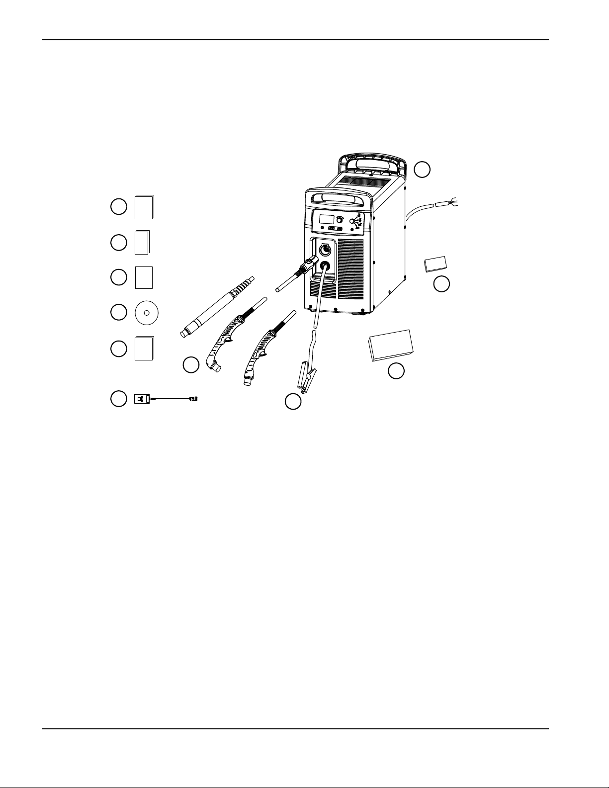
2 – Power Supply Setup
or
or
1
2
3
4
5
6
7
8
9
10
11
1
Operator Manual
2
Quick Setup Card
3
Registration card
4
Setup DVD
5
Safety and Compliance Manual
6
Remote-start pendant (optional)
7
Torches
8
Ground clamp and work lead
9
Starter consumable kit
10
Box with extra consumables (located next to air
filter)
11
Power supply
Contents
The following illustration shows typical system components. A vinyl cap is installed on torches that ship with new
systems. Consumables are included in the starter consumable kit, and the small consumables box next to the air filter
contains spare electrodes and nozzles.
Position the power supply
Locate the power supply near an appropriate power receptacle for your installation:
480 V (3-phase, CSA certified)
600 V (3-phase, CSA certified)
400 V (3-phase, CE certified)
380 V (3-phase, CCC certified)
CSA and CE certified power supplies include a 3 m (10 foot) power cord (depending on the model). CCC certified
power supplies do not ship with a power cord. To maintain CE certification, install power cord kit 228886.
30 Powermax125 Service Manual 808070
Page 31

2 – Power Supply Setup
Allow at least 0.25 m (10 inches) of space around the power supply for proper ventilation.
The power supply is not suitable for use in rain or snow.
To avoid toppling, do not set the power supply on an incline greater than 10 degrees.
Prepare the electrical power
Hypertherm (designated HYP on the data plate) input current ratings are used to determine conductor sizes for power
connection and installation instructions. The HYP rating is determined under maximum normal operating conditions, and
the higher HYP input current value should be used for installation purposes.
CAUTION!
Protect the circuit with appropriately sized time-delay (slow-blow) fuses and a line-disconnect switch.
The maximum output voltage will vary based on your input voltage and the circuit’s amperage. Because the current draw
varies during startup, slow-blow fuses are recommended as shown in Power connection for the Powermax125 on
page 32. Slow-blow fuses can withstand currents up to ten times the rated value for short periods of time.
Install a line-disconnect switch
Use a line-disconnect switch for each power supply so that the operator can turn off the incoming power quickly in an
emergency. Locate the switch so that it is easily accessible to the operator. Installation must be performed by a licensed
electrician according to national and local codes. The interrupt level of the switch must equal or exceed the continuous
rating of the fuses. In addition, the switch should:
Isolate the electrical equipment and disconnect all live conductors from the incoming supply voltage when in the OFF
position.
Have one OFF and one ON position that are clearly marked with O (OFF) and I (ON).
Have an external operating handle that can be locked in the OFF position.
Contain a power-operated mechanism that serves as an emergency stop.
Have appropriate slow-blow fuses installed. See Power connection for the Powermax125 on page 32 for
recommended fuse sizes.
Requirements for grounding
To ensure personal safety, proper operation, and to reduce electromagnetic interference (EMI), the power supply must be
properly grounded.
The power supply must be grounded through the power cord according to national and local electrical codes.
Three-phase service must be of the 4-wire type with a green or green/yellow wire for protective earth ground and
must comply with national and local requirements.
Refer to the separate Safety and Compliance Manual included with your system for more information on grounding.
Powermax125 Service Manual 808070 31
Page 32

2 – Power Supply Setup
Power connection for the Powermax125
Powermax125 3-phase systems are available in the following fixed-voltage configurations:
480 V CSA
600 V CSA
400 V CE
380 V CCC
To maintain CE certification, install power cord kit 228886.
The Hypertherm rated output is 30 – 125 A, 175 VDC.
Table 4 – 480 V CSA
Input voltage (V) 480
Input current (A) at rated output (21.9 kW) 31
Input current (A) at arc stretch 50
Fuse, slow-blow (A) 50
Voltage tolerance +20% / -15%
Table5 – 600V CSA
Input voltage (V) 600
Input current (A) at rated output (21.9 kW) 24
Input current (A) at arc stretch 38
Fuse, slow-blow (A) 40
Voltage tolerance +10% / -15%
Table6 – 400V CE
Input voltage (V) 400
Input current (A) at rated output (21.9 kW) 36
Input current (A) at arc stretch 55
Fuse, slow-blow (A) 60
Voltage tolerance +20% / -15%
32 Powermax125 Service Manual 808070
Page 33

2 – Power Supply Setup
Table 7 – 380 V CCC
Input voltage (V) 380
Input current (A) at rated output (21.9 kW) 38
Input current (A) at arc stretch 55
Fuse, slow-blow (A) 60
Voltage tolerance +20% / -15%
Three-phase power cord and plug installation
Powermax125 power supplies ship with the following power cords:
CSA models: 8 AWG 4-wire power cord (no power plug included)
CE models: 10 mm
CCC certified configurations do not ship with a power cord. To maintain CE certification, install power cord kit 228886.
2
4-wire HAR power cord (no power plug included)
If you need to install a different power cord on the system, the cable you use must have a diameter within one of the
following ranges to ensure a proper fit in the power cord strain relief:
CSA and CCC models: 15.0 – 25.4 mm (0.59 – 1.00 inches)
CE models: 20.0 – 25.9 mm (0.79 – 1.02 inches)
To operate the Powermax, use a plug that meets national and local electrical codes. The plug must be connected to the
power cord by a licensed electrician.
Decrease output current for lower-rated power plugs
To operate the power supply at full output and 100% duty cycle as rated, you must size your electrical service
accordingly. To operate the power supply using a lower-rated power plug or service, you must turn down the current
(amperage setting).
For more information on setting the current, see Adjusting the current (amperage) on
page 48.
Example: Tab le 8 shows the recommended output current for operating a 400 V CE power supply installed with a 32 A
power plug. To operate at 400 V in this scenario, run the power supply at 109 A to maintain 100% duty cycle.
Table 8 – Recommended ratings for operating 400 V CE unit on 32 A power plug
Input voltage Phase Recommended output current to maintain 100% duty cycle
380 V 3 104 A
400 V 3 109 A
415 V 3 114 A
Powermax125 Service Manual 808070 33
Page 34

2 – Power Supply Setup
L1
L2
L3
L1
L2
L3
Ground
419 mm (16.5 inches)
203 mm
(8 inches)
6mm (0.25inch)
Route lead through strain relief
and tighten
CSA/CCC power cords
(no ferrite cores)
CE power cord
(ferrite cores on power
wires and ground wire)
Strip and prepare the power cord wires as shown in the following figure. For CE units, ferrite cores are installed around
the three power wires and around the ground wire; CSA and CCC models do not have ferrite cores on the power cord
wires.
CCC models do not ship with a power cord. To maintain CE certification, install power
cord kit 228886.
34 Powermax125 Service Manual 808070
Page 35

2 – Power Supply Setup
Extension cord recommendations
Any extension cord must have an appropriate wire size for the cord length and system voltage. Use a cord that meets
national and local codes.
For all Powermax125 configurations, the recommended gauge size for any three-phase extension cord between
3 – 45 m (10 – 150 feet) is 10 mm
2
(8 AWG).
Engine-driven generator recommendations
Generators used with the Powermax125 should satisfy the voltage requirements in the following table and in Hypertherm
power supply ratings on page 22.
Engine drive rating System output current Performance (arc stretch)
40 kW 125 A Full
30 kW 125 A Limited
30 kW 10 0 A Full
25 kW 100 A Limited
22.5 kW 75 A Full
20 kW 75 A Limited
20 kW 60 A Full
15 kW 60 A Limited
12 kW 40 A Full
10 kW 40 A Limited
10 kW 30 A Full
8 kW 30 A Limited
Based on the generator rating, age, and condition, adjust the cutting current as needed.
If a fault occurs while using a generator, turning the power switch quickly to OFF and then
to ON again (sometimes called a “quick reset”) may not clear the fault. Instead, turn OFF
the power supply and wait 60 to 70 seconds before turning it ON again.
Powermax125 Service Manual 808070 35
Page 36

2 – Power Supply Setup
Water and particle
filter
Oil filter Oil vapor filter
Gas supply Powermax
Prepare the gas supply
The air can be supplied by a compressor or from high-pressure cylinders. A high-pressure regulator must be used on
either type of supply and must be capable of delivering gas to the air inlet on the power supply.
CAUTION!
Synthetic lubricants containing esters that are used in some air compressors will damage
polycarbonates used in the air regulator bowl.
The system contains a built-in filter element, but additional filtration may be required depending on the quality of the gas
supply. If the supply quality is poor, cut speeds decrease, cut quality deteriorates, cutting thickness capability decreases,
and the life of the consumables shortens. For optimal performance, the gas should be compliant with ISO8573-1:2010,
Class 1.2.2 (that is, it should have a maximum number of solid particulate per meter cubed of 20,000 for particle sizes in
the range of 0.1 – 0.5 microns, a maximum of 400 for particle sizes in the range of 0.5 – 1 microns, and a maximum of 10
for particle sizes in the range of 1 – 5 microns). The maximum water vapor dew point should be -40° C (-40° F). The
maximum oil (aerosol, liquid, and vapor) content should be 0.1 mg/m
3
.
Additional gas filtration
When site conditions introduce moisture, oil, or other contaminants into the gas line, use a 3-stage coalescing filtration
system, such as the Eliminizer filter kit (228890) available from Hypertherm distributors. A 3-stage filtering system works
as follows to clean contaminants from the gas supply.
The filtering system should be installed between the gas supply and the power supply. Additional gas filtration may
require higher pressure from the source.
36 Powermax125 Service Manual 808070
Page 37

2 – Power Supply Setup
The recommended inlet pressure while gas is
flowing is 5.9–9.3bar (85–135psi).
Connect the gas supply
Connect the gas supply to the power supply using an inert-gas hose with a 9.5 mm (3/8 inch) internal diameter and a
1/4 NPT quick-disconnect coupler (CSA units) or a 1/4 NPT x G-1/4 BSPP (CE/CCC units) quick-disconnect coupler.
WARNING!
Do not allow the gas supply pressure to exceed 9.3 bar (135 psi). The filter bowl may explode if this
pressure is exceeded.
Powermax125 Service Manual 808070 37
Page 38

2 – Power Supply Setup
Minimum inlet pressure (while gas is flowing)
This table shows the minimum required inlet pressure when the recommended inlet pressure is not available.
Torch lead length 7.6 m (25 feet) 15.2 m (50 feet) 22.9 m (75 feet)
Process Minimum inlet pressure
Cutting 5.9 bar (85 psi) 5.9 bar (85 psi) 6.6 bar (95 psi)
Gouging 4.1 bar (60 psi) 4.1 bar (60 psi) 4.1 bar (60 psi)
Gas flow rates
Process Gas flow rate
Cutting 260 slpm (550 scfh, 9.2 scfm) at a minimum:
• 5.9 bar (85 psi) for 7.6 m (25 foot) and 15 m (50 foot) torches
• 6.6 bar (95 psi) for 23 m (75 foot) torches
Gouging 212 slpm (450 scfh, 7.5 scfm) at a minimum 4.1 bar (60 psi)
38 Powermax125 Service Manual 808070
Page 39

Section 3
Basic System Operations
Controls and indicators
Powermax power supplies have the following controls and indicators: ON/OFF switch, adjustment knob,
automatic/manual pressure setting mode selector, current/gas selector, operating mode switch, indicator LEDs, and a
status screen. These controls and indicators are described on the following pages.
Rear controls
ON (I)/OFF (O) power switch – Activates the power supply and its control circuits.
Powermax125 Service Manual 808070 39
Page 40

3 – Basic System Operations
Adjustment knob
Operating mode switch
Status screen
Fault LED (yellow)
Automatic/manual pressure
setting mode selector
Current/gas
selector
Power ON LED
(green)
Modes
AC
Front controls and LEDs
LEDs
Selectors
Power ON LED (green) – When illuminated, this LED indicates that the power switch has been set to
I (ON) and that the safety interlocks are satisfied. When blinking, the power supply has a fault.
Fault LED (yellow) – When illuminated, this LED indicates that there is a fault with the power supply.
Automatic/manual pressure setting mode selector – The selector switches between
automatic and manual mode. In automatic mode, the power supply automatically sets the gas
pressure based on the torch type and lead length, and the adjustment knob sets only the
amperage. In manual mode, the adjustment knob sets either the gas pressure or the amperage.
This LED is illuminated in manual mode.
Manual mode should be used by experienced users who need to
optimize the gas setting (override the automatic gas setting) for a
specific cutting application.
When you switch from manual mode to automatic mode, the power supply automatically sets the
gas pressure, and the amperage setting is unchanged. When you switch from automatic mode to
manual mode, the power supply remembers the previous manual gas pressure setting, and the
amperage setting is unchanged.
When you reset the power, the power supply remembers the previous mode, gas pressure, and
amperage settings.
40 Powermax125 Service Manual 808070
Current/gas selector – When in manual mode, this selector toggles between amperage and
gas pressure for manual adjustments using the adjustment knob.
Page 41

3 – Basic System Operations
1
2
3
4
5 6
7
8
9
1011
1 Torch is cutting
2 Torch start
3 Fault icon
4 Fault code
5 Visual pressure setting
6 Pressure setting
7 Pressure selection cursor
8 Current selection cursor
9 Current setting (amperage)
10 Electrode end of life detection manually disabled
11 Remote connected
Operating mode switch
For more information on these modes, see Set the operating mode switch on page 47.
The operating mode switch can be set in one of four positions:
Continuous pilot arc. Cuts expanded metal or grate.
Non-continuous pilot arc. Cuts or pierces metal plate. This is the standard
setting for normal drag-cutting.
Gouge. Gouges metal plate.
Torch lock. Same as the non-continuous pilot arc mode except the torch is
locked in the ON position when you release the trigger during a cut. The torch
goes out when the transfer is lost or the torch is retriggered.
Amperage adjustment knob
Status screen
This knob adjusts the amperage. When operating in manual mode, you can also use this knob
to adjust the gas pressure, overriding the automatic setting for optimized applications.
Powermax125 Service Manual 808070 41
Page 42

3 – Basic System Operations
Gas pressure indicators
In manual mode, the gas pressure is displayed in measurements of bar and psi. The gas pressure bar is also a visual
indicator of the gas pressure.
Gas pressure bar – When the arrow is centered in the vertical bar (the reference pressure of the
automatic pressure setting), the gas pressure is set to the preset (factory-defined) value. If the pressure is
higher than the preset value, the arrow appears above the mid-point of the bar. If the pressure is lower
than the preset value, the arrow appears below the mid-point of the bar.
In automatic mode, the power supply adjusts the pressure to the preset
value. You can use manual mode to adjust the pressure to satisfy the
needs of a particular cutting job. See Manually adjusting the gas pressure
on page 48.
System status icons
The screen displays icons to indicate the system’s status.
Torch star t ed – Indicates that the torch has received a start signal.
Torch is cutting – Indicates that the cutting arc has transferred to the metal, and the torch is cutting.
Remote control – Indicates that a remote control or CNC is controlling the power supply using serial
communications. All local controls are disabled.
Electrode end-of-life detection manually disabled – Indicates that the electrode end-of-life
detection feature is manually disabled.
Fault codes and icons
When a power supply or torch fault occurs, the system displays a fault code in the lower-left corner of the status screen
and displays a corresponding fault icon above the code.
Fault code – The first digit is always zero. The other two digits identify the problem. Fault code
information is included later in this manual.
Only one fault code is displayed. If more than one fault occurs at the
same time, only the fault code with the highest priority is displayed.
Fault icon – The fault icons that appear on the left side of the status screen are described below. A
fault code also appears to identify the fault. Refer to the troubleshooting information later in this manual.
Warning – The system continues to run.
42 Powermax125 Service Manual 808070
Page 43

3 – Basic System Operations
Fault – The system stops cutting. If you cannot correct the problem and restart the system,
contact your distributor or Hypertherm Technical Service.
Error – The system requires service. Contact your distributor or Hypertherm Technical Service.
Torch cap sensor – Indicates that the consumables are loose, improperly installed, or missing.
Turn OFF the power, properly install the consumables, and turn ON the system again to reset the
power supply.
Temperature – Indicates that the temperature of the power supply power module is outside the
acceptable operating range.
Gas – Indicates that the gas is disconnected from the rear of the power supply or there is a
problem with the gas supply.
Internal Serial Communications Interface – Indicates a problem with communications
between the control board and the DSP board.
Powermax125 Service Manual 808070 43
Page 44

3 – Basic System Operations
Torch l ea d
Work lead
Power cord (does not
ship with plug)
Gas supply line
Operating the Powermax
Follow the steps below to begin cutting or gouging with the system.
This section provides basic operating instructions. Before operating your system in a
production environment, refer to Hand Torch Setup on page 51 or Machine Torch Setup
on page 67.
Connect the electrical power, gas supply, and torch lead
For information on connecting the proper plug to the power cord, refer to Power Supply Setup on page 29.
Plug in the power cord and connect the gas supply line. For more information about the electrical requirements and the
gas supply requirements of the Powermax, see Power Supply Setup on page 29. To connect the torch, push the
FastConnect connector into the receptacle on the front of the power supply. You will attach the work lead in the next step.
CCC units do not ship with a power cord. To maintain CE certification, install power cord
kit 228886.
44 Powermax125 Service Manual 808070
Page 45

3 – Basic System Operations
Work lead receptacle
on power supply
Keyed opening at
top of receptacle
Attach the work lead to the power supply
CAUTION!
Make sure you use a work lead that is appropriate for your power supply. Use a 125 A work lead with
the Powermax125. The amperage is marked near the rubber boot of the work lead connector.
1. Insert the work lead connector into the receptacle on the front of the power supply.
The receptacle is keyed. Align the key on the work lead connector with the opening at the
top of the receptacle on the power supply.
2. Push the work lead connector all the way into the receptacle on the power supply and turn clockwise, approximately
1/4 turn, until the connector is fully seated against the stop in order to achieve an optimal electrical connection.
A loose connection will overheat the connector. Frequently check the work lead for a
reliable electrical connection.
CAUTION!
Make sure the work lead is fully seated in the receptacle to prevent overheating.
Powermax125 Service Manual 808070 45
Page 46

3 – Basic System Operations
Ground clamp
OFF
ON
Attach the ground clamp to the workpiece
The ground clamp must be connected to the workpiece while you are cutting. If you are using the Powermax with a
cutting table, you can connect the work lead directly to the table instead of attaching the ground clamp to the workpiece.
See your table manufacturer’s instructions.
Make sure that the ground clamp and the workpiece make good metal-to-metal contact.
Remove rust, dirt, paint, coatings, and other debris to ensure the work lead makes proper
contact with the workpiece.
For the best cut quality, attach the ground clamp as close as possible to the area being
cut.
CAUTION!
Do not attach the ground clamp to the portion of the workpiece to be cut away.
Turn on the system
Set the ON/OFF switch to the ON (I) position.
46 Powermax125 Service Manual 808070
Page 47

3 – Basic System Operations
Set the operating mode switch
Use the operating mode switch to select the type of work you want to perform.
In automatic gas mode, Smart Sense technology automatically adjusts the gas pressure according to the selected cutting
mode and torch lead length for optimum cutting.
For cutting expanded metal, grates, metal containing holes, or any job that
requires a continuous pilot arc. Using this mode to cut standard metal plate
reduces consumable life.
For cutting or piercing metal. This is the standard setting for normal drag-cutting.
For gouging metal.
Using this mode while cutting results in poor cut
quality.
For locking the torch in the ON (fire) position. With this option selected, press the
trigger to fire the torch. The trigger will remain on when you release the trigger.
The arc will go out when transfer is lost or you press the trigger again.
Check the indicators
Verify the following:
The green power ON LED on the front of the power supply is illuminated.
The Fault LED is not illuminated.
No error icons appear in the status screen.
If a fault icon appears in the status screen, or the Fault LED is illuminated, or the power ON LED is blinking, correct the
fault condition before continuing. More troubleshooting information is included later in this manual.
Powermax125 Service Manual 808070 47
Page 48

3 – Basic System Operations
Manually adjusting the gas pressure
For normal operations, the power supply automatically adjusts the gas pressure. If you need to adjust the gas pressure for
a specific application, you can use manual mode to do so.
Manual mode should be used by experienced users who need to optimize the gas setting
(override the automatic gas setting) for a specific cutting application.
When you switch from manual mode to automatic mode, the power supply automatically sets the gas pressure, and the
amperage setting is unchanged. When you switch from automatic mode to manual mode, the power supply remembers
the previous manual gas pressure setting, and the amperage setting is unchanged.
When you reset the power, the power supply remembers the previous mode, gas pressure, and amperage settings.
To adjust the pressure:
1. Press the automatic/manual pressure setting mode selector so that the LED next to the selector illuminates. Refer to
Front controls and LEDs on page 40.
2. Press the current/gas selector until the selection cursor is opposite the gas pressure setting in the status screen.
3. Turn the adjustment knob to adjust the gas pressure to the desired level. Watch the arrow in the pressure bar as you
adjust the pressure. (See Gas pressure indicators on page 42.)
Adjusting the current (amperage)
Turn the adjustment knob to adjust the current for your particular cutting application.
If the system is in manual mode, do the following to adjust the amperage:
1. Press the current/gas selector until the selection cursor is opposite the amperage setting in the status screen.
2. Turn the adjustment knob to change the amperage.
3. If you wish to exit manual mode, press the automatic/manual pressure setting mode selector. The LED goes off.
When you exit manual mode, the gas pressure resets to the factory-optimized value.
When you switch between manual mode and automatic mode, the power supply retains the amperage setting. When you
reset the power, the power supply returns to the previous mode (automatic mode or manual mode) and remembers the
previous amperage setting.
48 Powermax125 Service Manual 808070
Page 49

3 – Basic System Operations
Electrode end-of-life detection manually disabled
Current/gas selector
Electrode end-of-life detection feature
The electrode end-of-life detection feature on the system protects the torch and workpiece from damage by automatically
stopping power to the torch when the electrode reaches its end of life. Fault code 0-32 also displays on the front panel
status screen. If you have the current set below 55 A, this feature is automatically disabled without displaying the icon on
the status screen.
To manually disable the feature:
1. Set the system to auto mode.
2. Press the current/gas selector button (see Figure 1) 5 times in quick succession, less than one second apart.
The icon (see Figure 1) displays on the status screen.
3. To re-enable the feature, press the current/gas selector button 5 times again in quick succession, less than one
second apart.
The icon disappears.
Figure 1 – Front panel controls
Powermax125 Service Manual 808070 49
Page 50

3 – Basic System Operations
Understanding duty-cycle limitations
The duty cycle is a percentage of time out of 10 minutes that a plasma arc will remain on when operating at an ambient
temperature of 40° C (104° F). For example, if the system runs for 6 minutes before overheating and cools off enough to
produce an arc in less than 4 minutes, it has a 60% duty cycle.
If the power supply overheats, the temperature fault icon appears in the status screen, the arc shuts off, and the cooling
fan continues to run. You cannot resume cutting until the temperature fault icon disappears and the fault LED goes off.
The fan may run during normal operation of the system.
With a Powermax125:
At 125 A (480/600 V CSA, 400 V CE, 380 V CCC), the arc can remain on for 10 minutes out of 10 minutes without
causing the unit to overheat (100% duty cycle).
If you are operating the power supply using a lower-rated power plug or service, turn
down the current (amperage setting). See Decrease output current for lower-rated power
plugs on page 33.
50 Powermax125 Service Manual 808070
Page 51

Section 4
Hand Torch Setup
Introduction
Duramax Hyamp series hand torches are available for Powermax125 systems. The FastConnect quick-disconnect system
makes it easy to remove the torch for transport or to switch from one torch to the other if your applications require the use
of different torches. The torches are cooled by ambient air and do not require special cooling procedures.
This section explains how to set up your hand torch and choose the appropriate consumables for the job.
Consumable life
How often you need to change the consumables on your torch will depend on a number of factors:
The thickness of the metal being cut.
The average length of the cut.
The air quality (presence of oil, moisture, or other contaminants).
Whether you are piercing the metal or starting cuts from the edge.
Proper torch-to-work distance when gouging.
Proper pierce height.
Whether you are cutting in “continuous pilot arc” mode or normal mode. Cutting with a continuous pilot arc causes
more consumable wear.
Under normal conditions, the nozzle will wear out first when hand cutting. As general rule, a set of consumables lasts
approximately 1 to 3 hours of actual “arc on” time for 125 A hand cutting. Cutting at lower amperages may yield longer
consumable life.
You will find more information about proper cutting techniques in Hand Cutting on page 57.
Powermax125 Service Manual 808070 51
Page 52

4 – Hand Torch Setup
Consumables
Safety trigger
Consumables
Safety trigger
Hand torch components
The hand torches ship without consumables installed.
Duramax Hyamp 85° hand torch
Duramax Hyamp 15° hand torch
Choose the hand torch consumables
Hypertherm includes a starter consumable kit and a box of spare electrodes and nozzles with your system. Both styles of
hand torches shown above use the same consumables.
Hand torches use shielded consumables. Therefore, you can drag the torch tip along the metal.
Consumables for hand cutting are shown below. Notice that the retaining cap and electrode are the same for cutting,
gouging, and FineCut
®
applications. Only the shield, nozzle, and swirl ring are different.
For the best cut quality on thin materials (approximately 4 mm/10 GA or less), you may prefer to use FineCut
consumables, or use a 45 A nozzle and reduce the amperage to that setting.
52 Powermax125 Service Manual 808070
Page 53
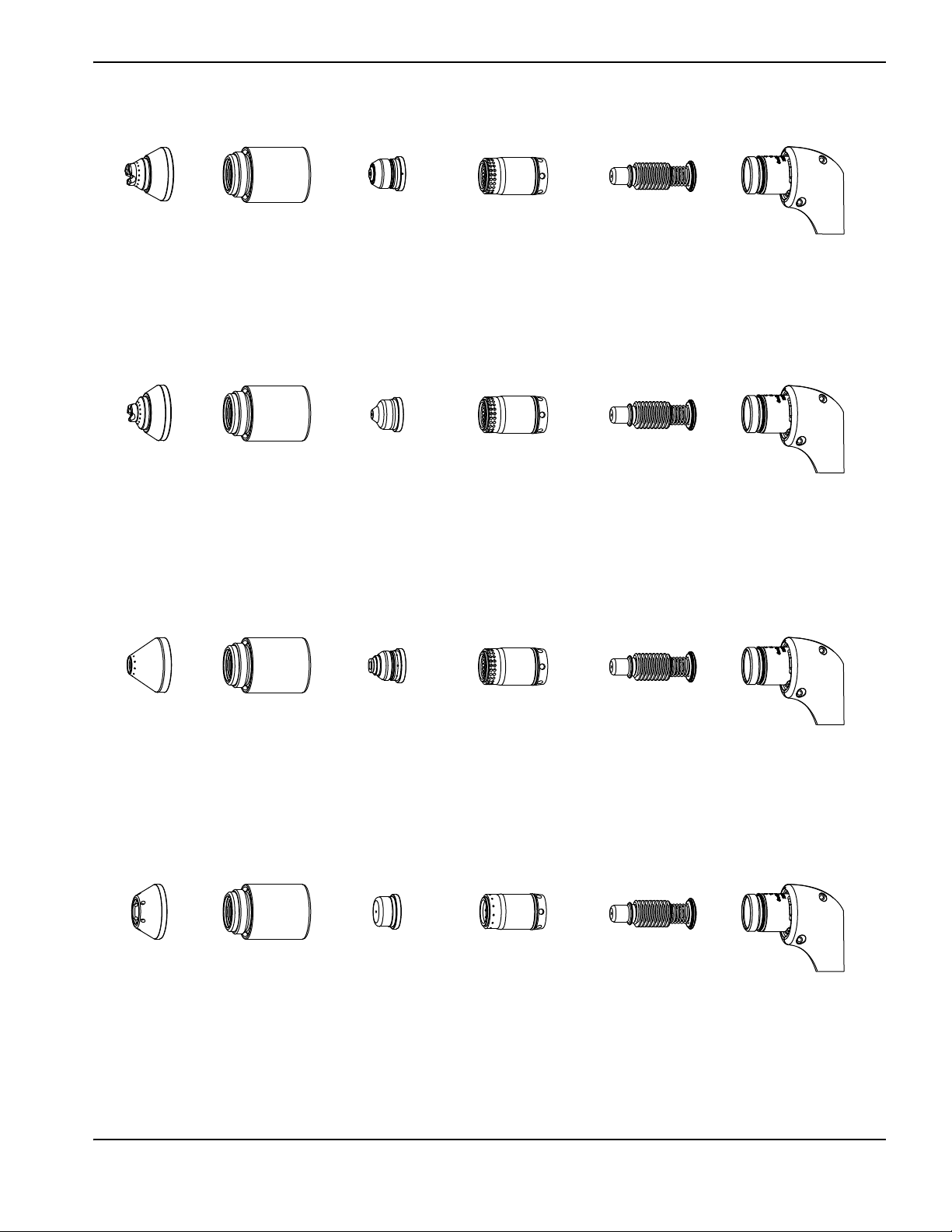
Drag-cutting 105/125 A consumables
420000
Shield
220977
Retaining cap
220975
Nozzle
220997
Swirl ring
220971
Electrode
420172
Shield
220977
Retaining cap
420158 (45 A)
420169 (65 A)
Nozzle
220997
Swirl ring
220971
Electrode
420112
Shield
220977
Retaining cap
420001
Nozzle
220997
Swirl ring
220971
Electrode
420152
Shield
220977
Retaining cap
420151
Nozzle
420159
Swirl ring
220971
Electrode
Drag-cutting 45 A and 65 A consumables
4 – Hand Torch Setup
Gouging consumables
FineCut consumables
Powermax125 Service Manual 808070 53
Page 54

4 – Hand Torch Setup
Shield
Retaining cap
Nozzle
Electrode
Swirl ring
Install the hand torch consumables
WARNING!
INSTANT-ON TORCHES
PLASMA ARC CAN CAUSE INJURY AND BURNS
The plasma arc comes on immediately when the torch trigger is activated. Make sure the
power is OFF before changing consumables.
To operate the hand torch, a complete set of consumable parts must be installed: shield, retaining cap, nozzle, electrode,
and swirl ring. Torches ship without consumables installed. Pull off the vinyl cap before installing your consumables.
With the power switch in the OFF (O) position, install the Powermax125 torch consumables as shown.
54 Powermax125 Service Manual 808070
Page 55

4 – Hand Torch Setup
Red button
Connecting the torch lead
The system is equipped with FastConnect, a quick-disconnect system for connecting and disconnecting handheld and
machine torch leads. When connecting or disconnecting a torch, first turn OFF the system. To connect the torch, push
the connector into the receptacle on the front of the power supply.
To remove the torch, press the red button on the connector and pull the connector out of the receptacle.
Powermax125 Service Manual 808070 55
Page 56

4 – Hand Torch Setup
56 Powermax125 Service Manual 808070
Page 57
Section 5
Hand Cutting
Using the hand torch
WARNING!
INSTANT-ON TORCHES
PLASMA ARC CAN CAUSE INJURY AND BURNS
Plasma arc comes on immediately when the torch trigger is activated. The plasma arc will cut quickly
through gloves and skin.
Wear correct and appropriate protective equipment.
Keep hands, clothing, and objects away from the torch tip.
Do not hold the workpiece and keep your hands clear of the cutting path.
Never point the torch toward yourself or others.
Powermax125 Service Manual 808070 57
Page 58

5 – Hand Cutting
1
2
3
90°
Operate the safety trigger
The hand torches are equipped with a safety trigger to prevent accidental firings. When you are ready to use the torch,
flip the trigger’s safety cover forward (toward the torch head) and press the red torch trigger.
Hand torch cutting guidelines
Drag the torch tip lightly along the workpiece to maintain a steady cut.
While cutting, make sure that sparks exit from the bottom of the workpiece. The sparks should lag slightly behind the
torch as you cut (15 – 30° angle from vertical).
If sparks spray up from the workpiece, move the torch more slowly, or set the output current higher.
With either hand torch, hold the torch nozzle perpendicular to the workpiece so that the nozzle is at a 90° angle to the
cutting surface. Observe the cutting arc as the torch cuts.
58 Powermax125 Service Manual 808070
Page 59

5 – Hand Cutting
If you fire the torch unnecessarily, you will shorten the life of the nozzle and electrode.
Pulling, or dragging, the torch along the cut is easier than pushing it.
For straight-line cuts, use a straight edge as a guide. To cut circles, use a template or a radius cutter attachment (a
circle cutting guide).
Start a cut from the edge of the workpiece
1. With the ground clamp attached to the workpiece, hold the torch nozzle perpendicular (90°) to the edge of the
workpiece.
2. Press the torch’s trigger to start the arc. Pause at the edge until the arc has cut completely through the workpiece.
Powermax125 Service Manual 808070 59
Page 60

5 – Hand Cutting
3. Drag the torch tip lightly across the workpiece to proceed with the cut. Maintain a steady, even pace.
Pierce a workpiece
WARNING!
SPARKS AND HOT METAL CAN INJURE EYES AND BURN SKIN
When firing the torch at an angle, sparks and hot metal will spray out from the nozzle. Point the torch
away from yourself and others. Always wear proper protective equipment including gloves and eye
protection.
1. With the ground clamp attached to the workpiece, hold the torch at an approximate 30° angle to the workpiece with
the torch tip within 1.5 mm (1/16 inch) of the workpiece before firing the torch.
60 Powermax125 Service Manual 808070
Page 61

5 – Hand Cutting
2. Fire the torch while still at an angle to the workpiece. Slowly rotate the torch to a perpendicular (90°) position.
3. Hold the torch in place while continuing to press the trigger. When sparks exit below the workpiece, the arc has
pierced the material.
4. When the pierce is complete, drag the nozzle lightly along the workpiece to proceed with the cut.
Powermax125 Service Manual 808070 61
Page 62

5 – Hand Cutting
30–45°
Direction of
travel
Gouge a workpiece
WARNING!
SPARKS AND HOT METAL CAN INJURE EYES AND BURN SKIN
When firing the torch at an angle, sparks and hot metal will spray out from the nozzle. Point the torch
away from yourself and others. Always wear proper protective equipment including gloves and eye
protection.
1. Hold the torch so that the torch tip is slightly above the workpiece before firing the torch.
2. Hold the torch at a 30 – 45° angle to the workpiece, with a small gap between the torch tip and the workpiece. Press
the trigger to obtain a pilot arc. Transfer the arc to the workpiece.
3. Change the torch’s angle as needed to achieve the desired dimensions for the gouge. Refer to Varying the gouge
profile on page 64 and 125 A gouging profile chart on page 64.
4. Maintain the same angle to the workpiece as you feed into the gouge. Push the plasma arc in the direction of the
gouge you want to create. Keep a small distance between the torch tip and the molten metal to avoid reducing
consumable life or damaging the torch.
62 Powermax125 Service Manual 808070
Page 63

Gouge profile
Speed
Standoff
Angle
Operating parameters
Speed
508 – 1270 mm/min (20 – 50 ipm)
Standoff
6.4 – 10.2 mm (1/4 – 2/5 inch)
Angle
30 – 35°
Width
10 mm (0.4 inch)
Depth
7. 6 m m ( 0 .3 i nc h)
You can vary the gouge profile by varying the:
Speed of the torch over the workpiece
Torch-to-work standoff distance
Angle of the torch to the workpiece
Current output of the power supply
5 – Hand Cutting
Typical gouging profile
125 A
Metal removal rate on mild steel 12.5 kg/hour
(27 pounds/hour)
Powermax125 Service Manual 808070 63
Page 64

5 – Hand Cutting
Varying the gouge profile
Follow these recommendations to change the gouge profile as needed:
Increasing the speed of the torch will decrease width and decrease depth.
Decreasing the speed of the torch will increase width and increase depth.
Increasing the standoff of the torch will increase width and decrease depth.
Decreasing the standoff of the torch will decrease width and increase depth.
Increasing the angle of the torch (more vertical) will decrease width and increase depth.
Decreasing the angle of the torch (less vertical) will increase width and decrease depth.
Increasing the current of the power supply will increase width and increase depth.
Decreasing the current of the power supply will decrease width and decrease depth.
125 A gouging profile chart
The following tables show the 125 A gouging profile at 30° and 35° on mild steel. These settings are intended to serve as
a starting point to help you determine the best gouging profile for a given cutting job. Adjust these settings as needed for
your application and table to obtain the desired result.
Table 9 – Metric
Torch angle
30°
35°
Standoff
(mm)
6.3
10. 1
6.3
Speed
(mm/min)
Depth
(mm)
Width
(mm)
Width/depth
508 7.9 8.4 1.06
762 6.6 7.6 1.16
1016 5.5 6.6 1.21
1270 4.4 6.1 1.38
508 7.6 9.8 1.30
762 6.1 8.7 1.43
1016 4.8 7.3 1.50
1270 4.2 7.0 1.66
508 7.5 6.8 0.92
762 5.7 6.5 1.13
1016 4.5 5.7 1.26
1270 4.2 5.2 1.24
508 7.3 8.1 1.12
ratio
10. 1
762 5.7 7.5 1.30
1016 5.7 6.4 1.12
1270 4.4 6.0 1.35
64 Powermax125 Service Manual 808070
Page 65

Table 10 – English
5 – Hand Cutting
Torch angle
30°
35°
Standoff
(inches)
0.25
0.40
0.25
0.40
Speed
(ipm)
20 0.31 0.33 1.06
30 0.26 0.30 1.16
40 0.22 0.26 1.21
50 0.17 0.24 1.38
20 0.30 0.39 1.30
30 0.24 0.34 1.43
40 0.19 0.29 1.50
50 0.17 0.28 1.66
20 0.30 0.27 0.92
30 0.23 0.26 1.13
40 0.18 0.22 1.26
50 0.17 0.21 1.24
20 0.29 0.32 1.12
30 0.23 0.30 1.30
40 0.23 0.25 1.12
Depth
(inches)
Width
(inches)
Width/depth
ratio
50 0.18 0.24 1.35
Powermax125 Service Manual 808070 65
Page 66

5 – Hand Cutting
Common hand-cutting faults
The torch does not cut completely through the workpiece. The causes can be:
The cut speed is too fast.
The consumables are worn.
The metal being cut is too thick for the selected amperage.
Gouging consumables are installed instead of drag-cutting consumables.
The ground clamp is not attached properly to the workpiece.
The gas pressure or gas flow rate is too low.
Gouging mode is selected on the power supply.
Cut quality is poor. The causes can be:
The metal being cut is too thick for the amperage.
The wrong consumables are being used (gouging consumables are installed instead of drag-cutting consumables,
for example).
The torch is moving too quickly or too slowly.
The arc sputters and consumable life is shorter than expected. The causes can be:
Moisture in the gas supply.
Incorrect gas pressure.
Consumables incorrectly installed.
The consumables are worn.
66 Powermax125 Service Manual 808070
Page 67

Section 6
Machine Torch Setup
Introduction
Duramax Hyamp series machine torches are available for this system. The FastConnect quick-disconnect system makes it
easy to remove the torch for transport or to switch from one torch to the other if your applications require the use of
different torches. The torches are cooled by ambient air and do not require special cooling procedures.
This section explains how to set up your machine torch and choose the appropriate consumables for the job.
Consumable life
How often you need to change the consumables on your torch will depend on a number of factors:
The thickness of the metal being cut.
The average length of the cut.
The air quality (presence of oil, moisture, or other contaminants).
Whether you are piercing the metal or starting cuts from the edge.
Proper torch-to-work distance when gouging.
Proper pierce height.
Whether you are cutting in “continuous pilot arc” mode or normal mode. Cutting with a continuous pilot arc causes
more consumable wear.
Under normal conditions, the electrode will wear out first during machine cutting. As general rule, a set of consumables
should last about 1 to 3 hours for 125 A mechanized cutting, depending on the job. Cutting at lower amperages may
yield longer consumable life.
You will find more information about proper cutting techniques in Mechanized Cutting on page 99.
Powermax125 Service Manual 808070 67
Page 68

6 – Machine Torch Setup
1
2
3
4
6
8
7
1
4
5
8
3
7
2
1 Consumables
2 Strain relief
3 Strain relief nut
4 Torc h l ead
5 Adapter (not used in the full-length machine torch)
6 Positioning sleeve (not used in the mini machine
torch)
7 Coupler
8 Mounting sleeve
Machine torch components
Duramax Hyamp 180° machine torch
See the following callout table.
Duramax Hyamp 180° mini machine torch
Before using either style of machine torch, you must:
Mount the torch on your cutting table or other equipment.
Choose and install the consumables.
Align the torch square to the plate.
Attach the torch lead to the power supply.
Set up the power supply for remote starting with either the remote-start pendant or a machine interface cable.
68 Powermax125 Service Manual 808070
Page 69

6 – Machine Torch Setup
6
1
4
2
5
3
9
8
7
10
11
1 Mounting sleeve screws
2 Mounting sleeve
3 Cap-sensor switch and screw
4 Torch body
5 Coupler
6 Positioning sleeve (full-length machine torch only)
7 Adapter (mini machine torch only)
8 Pilot arc wire and screw
9 Torc h l ead
10 Strain relief
11 Strain relief nut
Disassemble the machine torch
You may need to disassemble the machine torch in order to mount it on a cutting table (see Mount the torch on page 72).
Another reason to disassemble the machine torch is to convert it from the full-length machine torch to a mini machine
torch (see Convert a full-length machine torch to a mini machine torch on page 71).
While disconnecting and reconnecting the torch parts, maintain the same orientation
between the torch head and torch lead. Twisting the torch head in relation to the torch
lead can cause damage to the torch wires.
1. Disconnect the torch lead from the power supply, and remove the consumables from the torch.
2. Unscrew the strain relief nut from the strain relief, and slide the nut back along the torch lead.
3. If you are disassembling the full-length machine torch, unscrew the strain relief from the positioning sleeve. If you are
disassembling the mini machine torch, unscrew the strain relief from the adapter. Slide the strain relief back along the
torch lead.
Powermax125 Service Manual 808070 69
Page 70

6 – Machine Torch Setup
4. If you are disassembling the full-length machine torch, unscrew the positioning sleeve from the coupler. If you are
disassembling the mini machine torch, unscrew the adapter from the coupler.
5. Unscrew the coupler from the mounting sleeve.
6. Remove the three screws from the consumables end of the mounting sleeve, and slide the mounting sleeve off the
front of the torch body.
7. Disconnect the wire connector for the cap-sensor switch.
8. Remove the screw that secures the torch’s pilot wire to the torch body.
9. Use 5/16-inch and 1/2-inch wrenches, or adjustable wrenches, to loosen the nut that secures the gas supply line to
the torch lead. Set the torch body aside.
10. Slide the coupler off the front of the torch lead.
11. If you are disassembling a full-length machine torch, slide the positioning sleeve off the front of the torch lead. If you
are disassembling a mini machine torch, slide the adapter off the front of the torch lead.
70 Powermax125 Service Manual 808070
Page 71

6 – Machine Torch Setup
6
1
4
2
5
3
7
9
8
10
1 Mounting sleeve screws
2 Mounting sleeve
3 Cap-sensor switch and screw
4 Torch body
5 Coupler
6 Adapter (428146)
7 Pilot arc wire and screw
8 Torc h l ead
9 Strain relief
10 Strain relief nut
Convert a full-length machine torch to a mini machine torch
You will need the mini machine torch adapter kit (428146) to complete the following procedure. This kit enables you to
convert a full-length machine torch to a mini machine torch by removing the positioning sleeve and installing a small
adapter ring in its place.
If you are converting a full-length machine torch to a mini machine torch and mounting the
torch at the same time, skip this procedure and follow the instructions in Mount the torch
on page 72.
1. Follow the instructions in Disassemble the machine torch on page 69.
2. Slide the adapter over the torch lead.
3. Slide the coupler over the torch lead.
4. Screw the adapter onto the coupler.
5. Reconnect the gas supply line to the torch lead.
6. Reattach the torch’s pilot wire to the torch body using the screw.
7. Reconnect the cap-sensor switch’s wire connector.
Powermax125 Service Manual 808070 71
Page 72

6 – Machine Torch Setup
8. Slide the mounting sleeve over the front of the torch body. Align the slot on the front of the mounting sleeve (next to
one of the three screw holes) with the cap-sensor plunger on the torch body.
9. Attach the mounting sleeve to the torch body using the three screws.
10. Screw the coupler onto the mounting sleeve.
11. Screw the strain relief onto the adapter.
12. Screw the strain relief nut onto the strain relief.
13. Reinstall the consumables in the torch, and reconnect the torch lead to the power supply.
Mount the torch
The machine torches can be mounted on a wide variety of X-Y tables, track burners, pipe bevelers, and other equipment.
Install the torch per the manufacturer’s instructions. Use the following procedure to disassemble and reassemble the
torch if you need to do so in order to route the torch through the cutting table’s track or other mounting system.
If your cutting table’s track is large enough for you to route the torch through it without removing the torch body from the
lead, do so and then attach the torch to the lifter per the manufacturer’s instructions.
While disconnecting and reconnecting the torch parts, maintain the same orientation
between the torch head and torch lead. Twisting the torch head in relation to the torch
lead can cause damage to the torch wires.
1. Follow the instructions in Disassemble the machine torch on page 69.
Cover the end of the gas line on the torch lead with tape to keep dirt and other
contaminants from getting in the gas line when you route the lead through the track.
2. Route the torch lead through the mounting system for the cutting table. Slide the strain relief and strain relief nut
along the torch lead as needed to move them out of the way as you route the torch lead through the track.
3. If you are mounting a full-length machine torch, slide the positioning sleeve over the torch lead. If you are mounting a
mini machine torch, slide the adapter over the torch lead.
4. Slide the coupler over the torch lead.
5. Reconnect the gas supply line to the torch lead.
6. Reattach the torch’s pilot wire to the torch body using the screw.
7. Reconnect the cap-sensor switch’s wire connector.
8. Slide the mounting sleeve over the front of the torch body. Align the slot on the front of the mounting sleeve (next to
one of the three screw holes) with the cap-sensor plunger on the torch body.
9. Attach the mounting sleeve to the torch body using the three screws.
10. Screw the coupler into the mounting sleeve.
72 Powermax125 Service Manual 808070
Page 73
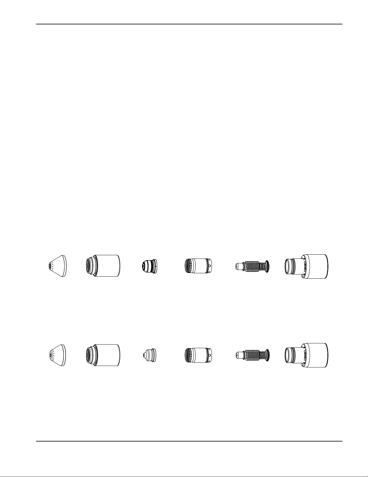
6 – Machine Torch Setup
220976
Shield
220975
Nozzle
220971
Electrode
220997
Swirl ring
220977
Retaining cap
420168
Shield
220977
Retaining cap
420158 (45 A)
420169 (65 A)
Nozzle
220971
Electrode
220997
Swirl ring
11. If you are mounting a full-length machine torch, screw the positioning sleeve into the coupler. If you are mounting a
mini machine torch, screw the adapter into the coupler.
12. Screw the strain relief into the positioning sleeve (for a full-length machine torch) or the adapter (for a mini machine
torch).
13. Screw the strain relief nut into the strain relief.
14. Attach the torch to the lifter per the manufacturer’s instructions.
15. Reinstall the consumables in the torch.
Choose the machine torch consumables
Systems with the Duramax Hyamp 180° full-length machine torch or Duramax Hyamp 180° mini machine torch ship with
a starter consumable kit as well as a box of spare electrodes and nozzles. There are two starter mechanized consumable
kits. One includes the standard retaining cap, and one includes the ohmic retaining cap. Notice that the retaining cap,
electrode, and swirl ring are the same for cutting, gouging, and FineCut applications. Only the shield and nozzle are
different.
Both styles of machine torches use the same consumables. Mechanized consumables are shielded. Therefore, if the torch
touches the workpiece it will not damage the nozzle.
Machine torch consumables
Mechanized shielded 105 A/125 A consumables
Mechanized shielded 45 A and 65 A consumables
Powermax125 Service Manual 808070 73
Page 74

6 – Machine Torch Setup
220976
Shield
420156
Ohmic-sensing
retaining cap
220975
Nozzle
220971
Electrode
220997
Swirl ring
420168
Shield
420156
Ohmic-sensing
retaining cap
420158 (45 A)
420169 (65 A)
Nozzle
220971
Electrode
220997
Swirl ring
420112
Shield
220977
Retaining cap
420001
Nozzle
220971
Electrode
220997
Swirl ring
420152
Shield
420151
Nozzle
220971
Electrode
220997
Swirl ring
220977
Retaining cap
Mechanized shielded with ohmic 105 A/125 A consumables
Mechanized shielded with ohmic 45 A and 65 A consumables
Gouging consumables
FineCut shielded consumables
74 Powermax125 Service Manual 808070
Page 75

FineCut shielded with ohmic consumables
420152
Shield
420156
Ohmic-sensing
retaining cap
420151
Nozzle
220971
Electrode
220997
Swirl ring
Mounting bracket
Install the machine torch consumables
PLASMA ARC CAN CAUSE INJURY AND BURNS
The plasma arc comes on immediately when the torch trigger is activated. Make sure the
power is OFF before changing consumables.
6 – Machine Torch Setup
WARNING!
INSTANT-ON TORCHES
To operate the machine torch, a complete set of consumable parts must be installed: shield, retaining cap, nozzle,
electrode, and swirl ring.
With the power switch in the OFF (O) position, install the machine torch consumables in a manner similar to the hand
torch consumables. See Hand Torch Setup on page 51.
Aligning the torch
Mount the machine torch perpendicular to the workpiece in order to get a vertical cut. Use a square to align the torch at
right angles to the workpiece.
Position the mounting bracket as low on the torch as possible to minimize vibration at the
tip of the torch.
Powermax125 Service Manual 808070 75
Page 76

6 – Machine Torch Setup
Red button
Connecting the torch lead
This system is equipped with FastConnect, a quick-disconnect system for connecting and disconnecting handheld and
machine torch leads. When connecting or disconnecting a torch, first turn OFF the system. To connect the torch, push
the connector into the receptacle on the front of the power supply.
To remove the torch, press the red button on the connector and pull the connector out of the receptacle.
76 Powermax125 Service Manual 808070
Page 77

6 – Machine Torch Setup
Using the cut charts
The following tables provide cut charts for each set of mechanized consumables. For each consumable type, there are
metric and English charts for mild steel, stainless steel, and aluminum. A consumable diagram with part numbers
precedes each set of cut charts.
Each cut chart contains the following information:
Amperage setting – The amperage setting at the top left side of the page applies to all the settings given on that
page. In FineCut charts, the amperage setting for each thickness is included in the cut chart.
Material Thickness – Thickness of the workpiece (metal plate being cut).
Torch-to-Work Distance – Distance between the shield and the workpiece during cutting. This may also be known
as cut height.
Initial Pierce Height – Distance between the shield and the workpiece when the torch is triggered, prior to
descending to the cut height.
Pierce Delay Time – Length of time the triggered torch remains stationary at the pierce height before the torch
starts the cutting motion.
Best Quality Settings (cut speed and voltage) – Settings that provide the starting point for finding the best cut
quality (best angle, least dross, best cut-surface finish). Adjust the speed for your application and table to obtain the
desired result.
Production Settings (cut speed and voltage) – 70% to 80% of the maximum speed ratings. These speeds result in
the greatest number of cut parts, but not necessarily the best possible cut quality.
The arc voltage increases as the consumables wear, so the voltage setting may need to
be increased to maintain the correct torch-to-work distance. Some CNCs monitor the arc
voltage and adjust the torch lifter automatically.
Each cut chart lists hot and cold air flow rates.
Hot air flow rate – Plasma is on, the system is operating at running current, and the system is in a steady state at
the default system pressure (automatic mode).
Cold air flow rate – Plasma is off and the system is in a steady state with air flowing through the torch at the default
system pressure.
Hypertherm collected the cut chart data under laboratory test conditions using new
consumables.
Powermax125 Service Manual 808070 77
Page 78

78 Powermax125 Service Manual 808070
Estimated kerf-width compensation
6 – Machine Torch Setup
The widths in the following tables are for reference. The data are obtained with the “Best Quality” settings. Differences between installations and material
composition may cause actual results to vary from those shown in the tables.
Estimated kerf-width compensation – Metric (mm)
Process
0.5 1 2 3 6 8 10 12 16 20 25 30 32 35 40
Thickness (mm)
Mild steel
125A shielded 2.22.32.42.42.62.83.13.63.83.94.1
105 A shielded 2 2.1 2.2 2.3 2.4 2.5 2.7 3 3.2
65 A shielded 1.6 1.6 1.8 1.9 2.0 2.2 2.7 3.2 3.7
45 A shielded 1.6 1.4 1.3 1.5 1.6
FineCut 1.3 1.2 1.2 1.2
Stainless steel
125 A shielded 1.9 2.2 2.4 2.6 2.6 2.7 3.1 3 3 3.2 3.6
105 A shielded 1.6 1.9 2.2 2.3 2.4 2.5 2.9 2.9 2.9
65 A shielded 1.4 1.5 1.8 1.8 1.9 1.9 2.1 2.3
45 A shielded 1.4 1.2 1.2 1.5 1.7
FineCut 1.2 1.2 1.0 1.0
Aluminum
125 A shielded 2.3 2.5 2.6 2.6 2.8 2.9 2.8 2.9 3 3.3 3.7
105 A shielded 1.9 2.0 2.2 2.2 2.1 2.1 2.5 2.5 2.5
65 A shielded 1.9 1.9 1.9 1.9 2.0 2.0 2.1 2.2
45 A shielded 1.5 1.4 1.6 1.8
Page 79

Powermax125 Service Manual 808070 79
Estimated kerf-width compensation – English (inches)
Process
22 GA 18 GA 14 GA 10 GA 3/16 1/4 3/8 1/2 5/8 3/4 7/8 1 1-1/4 1-1/2
Thickness (inches)
Mild steel
125 A shielded 0.089 0.094 0.095 0.103 0.108 0.109 0.123 0.150 0.158
105 A shielded 0.080 0.088 0.091 0.094 0.099 0.103 0.107 0.125
65 A shielded 0.062 0.065 0.067 0.070 0.079 0.088 0.104 0.120 0.134 0.147
45 A shielded 0.062 0.048 0.052 0.061 0.062 0.064
FineCut 0.049 0.047 0.048 0.048
Stainless steel
125 A shielded 0.078 0.094 0.103 0.103 0.103 0.112 0.123 0.116 0.137
105 A shielded 0.067 0.085 0.091 0.094 0.093 0.111 0.116 0.116
65 A shielded 0.054 0.060 0.065 0.071 0.074 0.076 0.083 0.090
45 A shielded 0.056 0.042 0.048 0.062 0.065 0.068
FineCut 0.045 0.044 0.039 0.042
Aluminum
1/32 1/16 1/8 1/4 3/8 1/2 5/8 3/4 7/8 1 1-1/4 1-1/2
125 A shielded 0.091 0.103 0.104 0.110 0.119 0.101 0.112 0.116 0.140
105 A shielded 0.075 0.086 0.085 0.083 0.083 0.087 0.101 0.100
65 A shielded 0.074 0.074 0.075 0.077 0.079 0.082 0.085
45 A shielded 0.060 0.052 0.062 0.070
6 – Machine Torch Setup
Page 80

6 – Machine Torch Setup
220976
Shield
220975
Nozzle
220977
Retaining cap
220997
Swirl ring
220971
Electrode
220976
Shield
420156
Ohmic-sensing
retaining cap
220975
Nozzle
220997
Swirl ring
220971
Electrode
125 A shielded consumables
80 Powermax125 Service Manual 808070
Page 81

6 – Machine Torch Setup
125 A shielded cutting – mild steel
Air flow rate – slpm/scfh
Hot 260 / 550
Cold 345 / 730
Metric
Material
Thickness
Torch-to-Work
Distance
Initial Pierce Height
Pierce
Delay Time
mm mm mm % seconds mm/min volts mm/min volts
6
8 0.3 3800 158 4570 157
10 0.4 2750 158 3330 158
9.2 200
0.2 4980 158 5960 155
12 0.5 2050 157 2510 157
16
20 2.0 980 165 1140 164
4.6
11.5 250
0.6 1260 162 1660 164
25 3.5 610 169 780 167
30
32 400 174 500 172
35 340 177 430 175
Edge Start* 1.0
40 240 180 310 178
Best Quality Settings Production Settings
Cut Speed Voltage Cut Speed Voltage
580 169 510 167
English
Material
Thickness
Torch-to-Work
Distance
Initial Pierce Height
Pierce
Delay Time
Best Quality Settings Production Settings
Cut Speed Voltage Cut Speed Voltage
inches inches inches % seconds ipm volts ipm volts
1/4
3/8 0.4 114 158 138 158
0.36 200
0.2 188 158 225 155
1/2 0.5 75 158 93 158
5/8
3/4 0.8 42 164 48 163
7/8 2.0 31 168 37 166
0.18
0.45 250
0.6 50 162 66 164
1 3.5 23 169 30 167
1-1/4
1-1/2 11 179 14 177
* You can pierce thicknesses up to 32 mm (1-1/4 inch) if your CNC software and torch height control system enable you to
temporarily raise the torch in order to clear the puddle of dross that can form during the pierce. In Hypertherm’s Phoenix CNC
software, for example, this function is referred to as the “puddle jump height.” Using this piercing function may affect consumable
life.
Edge Start* 1.0
16 174 20 172
Powermax125 Service Manual 808070 81
Page 82

6 – Machine Torch Setup
125 A shielded cutting – stainless steel
Air flow rate – slpm/scfh
Hot 260 / 550
Cold 345 / 730
Metric
Material
Thickness
Torch-to-Work
Distance
Initial Pierce Height
Pierce
Delay Time
mm mm mm % seconds mm/min volts mm/min volts
6
8 4060 157 5550 157
10 2540 159 3700 157
9.2 200 0.5
12 2170 163 2710 157
16
20 1.2 940 167 1030 163
4.6
11.5 250
25
0.7 1140 165 1460 162
1.0
30 510 173 610 166
32 1.1 400 177 600 169
35
Edge Start
1.2
40 180 185 210 179
Best Quality Settings Production Settings
Cut Speed Voltage Cut Speed Voltage
5910 156 7690 157
540 172 760 166
320 180 450 173
English
Material
Thickness
Torch-to-Work
Distance
Initial Pierce Height
Pierce
Delay Time
Best Quality Settings Production Settings
Cut Speed Voltage Cut Speed Voltage
inches inches inches % seconds ipm volts ipm volts
1/4
3/8 104 158 154 157
0.36 200 0.5
220 156 288 157
1/2 78 163 98 158
5/8
3/4 1.2 40 167 43 163
0.18
0.45 250
7/8
1 1.0 20 173 29 166
1-1/4 1.1 16 177 24 169
Edge Start
0.7 45 165 58 162
0.8 30 168 35 164
1-1/2 1.2 9 183 12 177
82 Powermax125 Service Manual 808070
Page 83

6 – Machine Torch Setup
125 A shielded cutting – aluminum
Air flow rate – slpm/scfh
Hot 260 / 550
Cold 345 / 730
Metric
Material
Thickness
Torch-to-Work
Distance
Initial Pierce Height
Pierce
Delay Time
mm mm mm % seconds mm/min volts mm/min volts
6
8 0.3 5100 161 6100 157
10 0.4 2980 163 4020 159
9.2 200
0.2 7660 159 8560 156
12 0.5 2140 165 3070 162
16
20 2.0 1260 170 1500 167
4.6
11.5 250
0.6 1540 169 2090 163
25 3.5 850 174 1050 167
30
1.0 810 175 760 167
32 1.1 430 182 750 174
35
Edge Start
1.2
40 270 185 300 179
Best Quality Settings Production Settings
Cut Speed Voltage Cut Speed Voltage
370 183 580 176
English
Material
Thickness
Torch-to-Work
Distance
Initial Pierce Height
Pierce
Delay Time
Best Quality Settings Production Settings
Cut Speed Voltage Cut Speed Voltage
inches inches inches % seconds ipm volts ipm volts
1/4
3/8 0.4 124 163 166 158
0.36 200
0.2 284 159 320 156
1/2 0.5 80 166 114 162
5/8
3/4 0.8 52 170 62 167
7/8 2.0 44 171 52 167
0.18
0.45 250
0.6 61 169 83 163
13.53217540167
1-1/4
1-1/2 12 184 16 178
Edge Start 1.0
17 182 30 174
Powermax125 Service Manual 808070 83
Page 84

6 – Machine Torch Setup
220976
Shield
220975
Nozzle
220977
Retaining cap
220997
Swirl ring
220971
Electrode
220976
Shield
420156
Ohmic-sensing
retaining cap
220975
Nozzle
220997
Swirl ring
220971
Electrode
105 A shielded consumables
84 Powermax125 Service Manual 808070
Page 85

6 – Machine Torch Setup
105 A shielded cutting – mild steel
Air flow rate – slpm/scfh
Hot 283 / 600
Cold 345 / 730
Metric
Material
Thickness
Torch-to-Work
Distance
Initial Pierce Height
Pierce
Delay Time
mm mm mm % seconds mm/min volts mm/min volts
6
0.5 4110 158 4920 146
8 0.6 3220 158 3770 150
10 0.8 2410 159 2730 153
9.2 200
12 0.7 1810 163 1980 156
16
20 1.3 780 168 850 157
4.6
11.5 250
25
30 420 176 440 168
Edge Start
1.0 1050 165 1230 155
1.0
32 1.2 370 177 400 170
Best Quality Settings Production Settings
Cut Speed Voltage Cut Speed Voltage
540 174 580 162
English
Material
Thickness
Torch-to-Work
Distance
Initial Pierce Height
Pierce
Delay Time
Best Quality Settings Production Settings
Cut Speed Voltage Cut Speed Voltage
inches inches inches % seconds ipm volts ipm volts
1/4
3/8 0.75 100 158 114 152
0.36 200
0.5 156 158 186 147
1/2 0.75 66 163 73 156
5/8
3/4 1.0 33 168 35 156
0.18
0.45 250
1.0 42 165 49 155
7/8 2.0 26 169 30 158
1
Edge Start
1.0 21 175 22 163
1-1/4 1.2 15 177 16 170
Powermax125 Service Manual 808070 85
Page 86

6 – Machine Torch Setup
105 A shielded cutting – stainless steel
Air flow rate – slpm/scfh
Hot 283 / 600
Cold 345 / 730
Metric
Material
Thickness
Torch-to-Work
Distance
Initial Pierce Height
Pierce
Delay Time
mm mm mm % seconds mm/min volts mm/min volts
6
8 3650 159 3940 148
10 2230 160 2420 151
9.2 200 0.5
12 1460 162 1980 154
16
20 2.5 660 169 730 158
4.6
11.5 250
25
30 330 176 450 167
Edge Start
1.0 1050 166 950 156
1.0
32 1.2 290 177 420 169
Best Quality Settings Production Settings
Cut Speed Voltage Cut Speed Voltage
5320 158 5780 144
440 174 520 162
English
Material
Thickness
Torch-to-Work
Distance
Initial Pierce Height
Pierce
Delay Time
Best Quality Settings Production Settings
Cut Speed Voltage Cut Speed Voltage
inches inches inches % seconds ipm volts ipm volts
1/4
3/8 94 160 100 150
0.36 200 0.5
198 158 224 145
1/2 55 163 71 154
5/8
0.18
0.45 250
1.0 42 166 38 156
3/4 2.5 28 168 30 157
7/8
1 17 174 20 163
Edge Start
1.0
22 172 26 159
1-1/4 1.2 12 177 17 169
86 Powermax125 Service Manual 808070
Page 87

6 – Machine Torch Setup
105 A shielded cutting – aluminum
Air flow rate – slpm/scfh
Hot 283 / 600
Cold 345 / 730
Metric
Material
Thickness
Torch-to-Work
Distance
Initial Pierce Height
Pierce
Delay Time
mm mm mm % seconds mm/min volts mm/min volts
6
0.5 6340 158 6390 154
8 0.6 4330 162 4690 154
10 0.8 2660 164 3250 155
9.2 200
12 0.7 2020 167 2590 159
16
20 1.3 970 172 1020 161
4.6
11.5 250
25
30 460 180 580 174
Edge Start
1.0 1350 169 1550 157
1.0
32 1.2 390 182 490 176
Best Quality Settings Production Settings
Cut Speed Voltage Cut Speed Voltage
660 176 800 167
English
Material
Thickness
Torch-to-Work
Distance
Initial Pierce Height
Pierce
Delay Time
Best Quality Settings Production Settings
Cut Speed Voltage Cut Speed Voltage
inches inches inches % seconds ipm volts ipm volts
1/4
3/8
0.36 200
1/2 75 167 95 159
5/8
3/4 40 171 42 160
0.18
0.45 250
0.5 236 159 240 154
110 164 134 154
0.75
1.0
54 169 62 157
7/8 2.0 34 173 37 164
1
Edge Start
1.0 25 176 31 167
1-1/4 1.2 16 182 20 176
Powermax125 Service Manual 808070 87
Page 88

6 – Machine Torch Setup
220997
Swirl ring
220971
Electrode
420168
Shield
220977
Retaining cap
420169
Nozzle
420168
Shield
420156
Ohmic-sensing
retaining cap
420169
Nozzle
220997
Swirl ring
220971
Electrode
65 A shielded consumables
88 Powermax125 Service Manual 808070
Page 89

6 – Machine Torch Setup
65 A shielded cutting – mild steel
Air flow rate – slpm/scfh
Hot 222 / 470
Cold 250 / 530
Metric
Material
Thickness
Torch-to-Work
Distance
Initial Pierce Height
Pierce
Delay Time
mm mm mm % seconds mm/min volts mm/min volts
2
0.1 5930 122 7015 123
3 0.2 5150 123 6080 123
4
6 2815 125 3275 124
3.8 250
0.5
8 2080 127 2235 126
10
1.5
4.5 300
0.7 1520 129 1490 128
12 1.2 960 131 1140 130
16 6 400 2.0 656 136 740 135
20
Edge start
25 215 146 270 146
Best Quality Settings Production Settings
Cut Speed Voltage Cut Speed Voltage
4370 123 5145 123
355 141 450 140
English
Material
Thickness
Torch-to-Work
Distance
Initial Pierce Height
Pierce
Delay Time
Best Quality Settings Production Settings
Cut Speed Voltage Cut Speed Voltage
inches inches inches % seconds ipm volts ipm volts
16 GA
10 GA 190 123 224 123
3/16 0.2 149 124 174 123
0.15 250
0.1
248 122 294 122
1/4 0.5 100 125 116 124
3/8 0.7 65 129 62 128
1/2 0.18 300 1.2 30 132 40 131
0.06
5/8 0.24 400 2.0 23 136 30 135
3/4
7/8 12 143 15 143
Edge Start
15 140 19 139
1814610146
Powermax125 Service Manual 808070 89
Page 90

6 – Machine Torch Setup
65 A shielded cutting – stainless steel
Air flow rate – slpm/scfh
Hot 222 / 470
Cold 250 / 530
Metric
Material
Thickness
Torch-to-Work
Distance
Initial Pierce Height
Pierce
Delay Time
mm mm mm % seconds mm/min volts mm/min volts
2
0.1 7405 119 9970 121
3 0.2 6120 120 8240 122
4
3.8 250
0.5
6 2275 125 2840 125
8
10
1.5
0.7
4.5 300
12 1.2 720 133 925 130
16
20 320 141 345 141
Edge Start
Best Quality Settings Production Settings
Cut Speed Voltage Cut Speed Voltage
4840 122 6110 123
1505 127 1860 127
1115 130 1245 128
465 137 505 136
English
Material
Thickness
Torch-to-Work
Distance
Initial Pierce Height
Pierce
Delay Time
Best Quality Settings Production Settings
Cut Speed Voltage Cut Speed Voltage
inches inches inches % seconds ipm volts ipm volts
16 GA
10 GA 220 121 296 122
3/16 0.2 152 123 168 123
1/4 0.5 72 125 96 125
0.06
0.15 250
0.1
316 118 425 120
3/8 0.7 48 130 52 128
1/2 0.18 300 1.2 23 134 32 131
5/8
Edge Start
19 137 20 136
3/4 14 140 15 140
90 Powermax125 Service Manual 808070
Page 91

6 – Machine Torch Setup
65 A shielded cutting – aluminum
Air flow rate – slpm/scfh
Hot 222 / 470
Cold 250 / 530
Metric
Material
Thickness
Torch-to-Work
Distance
Initial Pierce Height
Pierce
Delay Time
mm mm mm % seconds mm/min volts mm/min volts
2
0.1 7805 123 10265 122
3 0.2 6565 125 8790 123
4
3.8 250
0.5
6 2845 129 4375 126
8
10
1.5
0.7
4.5 300
12 1.2 1055 139 1330 135
16
20 335 146 550 144
Edge Start
Best Quality Settings Production Settings
Cut Speed Voltage Cut Speed Voltage
5320 126 7320 124
2015 133 2750 129
1535 136 1650 132
640 143 805 140
English
Material
Thickness
Torch-to-Work
Distance
Initial Pierce Height
Pierce
Delay Time
Best Quality Settings Production Settings
Cut Speed Voltage Cut Speed Voltage
inches inches inches % seconds ipm volts ipm volts
1/16
1/8 250 125 336 123
1/4 0.5 95 130 152 126
3/8 0.7 65 135 68 131
0.06
0.15 250
0.1
328 123 428 122
1/2 0.18 300 1.2 35 140 48 136
5/8
3/4 16 145 24 143
Edge Start
26 143 32 140
Powermax125 Service Manual 808070 91
Page 92

6 – Machine Torch Setup
420168
Shield
220977
Retaining cap
420158
Nozzle
220997
Swirl ring
220971
Electrode
420168
Shield
420156
Ohmic-sensing
retaining cap
420158
Nozzle
220997
Swirl ring
220971
Electrode
45 A shielded consumables
92 Powermax125 Service Manual 808070
Page 93

6 – Machine Torch Setup
45 A shielded cutting – mild steel
Air flow rate – slpm/scfh
Hot 217 / 460
Cold 241 / 510
Metric
Material
Thickness
Torch-to-Work
Distance
Initial Pierce Height
Pierce
Delay Time
mm mm mm % seconds mm/min volts mm/min volts
0.5
1 8890 119 10760 120
0.5 2.0 400
0.0
1.5 0.1 8040 123 10160 123
2
0.3 6565 128 7770 125
3
4 2250 130 3550 130
1.5 3.8 250
0.4
6 0.5 1265 132 2050 130
Best Quality Settings Production Settings
Cut Speed Voltage Cut Speed Voltage
8890 118 12510 120
3725 129 4890 128
English
Material
Thickness
Torch-to-Work
Distance
Initial Pierce Height
Pierce
Delay Time
Best Quality Settings Production Settings
Cut Speed Voltage Cut Speed Voltage
inches inches inches % seconds ipm volts ipm volts
26 GA
22 GA 350 118 450 120
0.02 0.08 400
18 GA
16 GA 314 123 400 123
14 GA
12 GA
10 G A 100 1 30 1 64 1 30
0.06 0.15 250
0.0
0.1
0.2 270 128 320 125
0.4
350 118 500 120
350 119 400 120
185 129 216 127
3/16 0.5 74 131 108 130
1/4 0.6 43 132 73 130
Powermax125 Service Manual 808070 93
Page 94

6 – Machine Torch Setup
45 A shielded cutting – stainless steel
Air flow rate – slpm/scfh
Hot 217 / 460
Cold 241 / 510
Metric
Material
Thickness
Torch-to-Work
Distance
Initial Pierce Height
Pierce
Delay Time
mm mm mm % seconds mm/min volts mm/min volts
0.5
1 8890 113 10760 120
0.5 2.0 400
0.0
1.5 0.1 7825 117 10160 120
2
0.3 6095 122 8615 122
3
4 2185 126 2565 126
1.5 3.8 250
0.4
6 0.5 975 132 1020 132
Best Quality Settings Production Settings
Cut Speed Voltage Cut Speed Voltage
8890 113 12510 120
3585 123 4405 123
English
Material
Thickness
Torch-to-Work
Distance
Initial Pierce Height
Pierce
Delay Time
Best Quality Settings Production Settings
Cut Speed Voltage Cut Speed Voltage
inches inches inches % seconds ipm volts ipm volts
26 GA
22 GA 350 113 450 120
0.02 0.08 400
18 GA
16 GA 305 117 400 120
14 GA
12 GA
10 GA 100 124 134 124
0.06 0.15 250
0.0
0.1
0.2 250 122 360 122
0.4
350 113 500 120
350 113 400 120
175 123 206 123
3/16 0.5 68 128 58 128
1/4 0.6 30 133 35 133
94 Powermax125 Service Manual 808070
Page 95

6 – Machine Torch Setup
45 A shielded cutting – aluminum
Air flow rate – slpm/scfh
Hot 217 / 460
Cold 241 / 510
Metric
Material
Thickness
Torch-to-Work
Distance
Initial Pierce Height
Pierce
Delay Time
mm mm mm % seconds mm/min volts mm/min volts
1
0.0 9145 126 11100 124
2 0.1 7470 125 9210 124
3 0.2 4675 125 6190 125
1.5 3.8 250
4 0.4 3700 129 4845 127
6 0.5 1740 135 2795 132
English
Material
Thickness
Torch-to-Work
Distance
Initial Pierce Height
Pierce
Delay Time
inches inches inches % seconds ipm volts ipm volts
1/32
0.0 360 126 450 124
1/16 0.1 360 126 400 124
3/32 0.2 233 124 328 124
0.06 0.15 250
1/8 0.4 177 126 224 125
1/4 0.5 55 136 96 133
Best Quality Settings Production Settings
Cut Speed Voltage Cut Speed Voltage
Best Quality Settings Production Settings
Cut Speed Voltage Cut Speed Voltage
Powermax125 Service Manual 808070 95
Page 96

6 – Machine Torch Setup
420152
Shield
420151
Nozzle
220977
Retaining cap
220997
Swirl ring
220971
Electrode
420152
Shield
420156
Ohmic-sensing
retaining cap
420151
Nozzle
220997
Swirl ring
220971
Electrode
FineCut consumables
96 Powermax125 Service Manual 808070
Page 97

6 – Machine Torch Setup
FineCut – mild steel
Air flow rate – slpm/scfh
Hot 217/ 460
Cold 226 / 480
Metric
Material
Thickness
Current
Torch-to-Work
Distance
Initial Pierce Height
Pierce Delay
Time
mm A mm mm % seconds mm/min volts
0.5
0.6 4080 85
30
0.0
0.8 0.1 4065 85
1
1.5
40
1.5 2.25 150
2
3
45
4 1270 80
0.2 4825 81
0.4
0.5
Recommended
Cut Speed Voltage
4330 83
4825 79
4740 78
3445 80
English
Material
Thickness
Current
Torch-to-Work
Distance
Initial Pierce Height
Pierce Delay
Time
Recommended
Cut Speed Voltage
inches A inches inches % seconds ipm volts
26 GA
24 GA 160 85
22 GA
30
20 GA 160 85
18 GA
40
0.06 0.09 150
16 GA
14 GA
12 GA
45
0.0
0.1
0.2 190 80
0.4
0.5
175 82
160 85
190 79
190 78
165 80
10 G A 100 8 0
Powermax125 Service Manual 808070 97
Page 98

6 – Machine Torch Setup
FineCut – stainless steel
Metric
Material
Thickness
mm A mm mm % seconds mm/min volts
0.5
0.6 4825 77
0.8 0.1 4825 73
1
1.5
2
3
4 995 72
Current
30
40
45
Torch-to-Work
Distance
Initial Pierce Height
0.02 0.08 400
Air flow rate – slpm/scfh
Hot 217/ 460
Cold 226 / 480
Pierce Delay
Time
0.0
Recommended
Cut Speed Voltage
4825 77
0.2 4825 86
4825 72
0.4
0.5
4550 72
2335 70
English
Material
Thickness
Current
Torch-to-Work
Distance
Initial Pierce Height
Pierce Delay
Time
Recommended
Cut Speed Voltage
inches A inches inches % seconds ipm volts
26 GA
24 GA 190 77
22 GA
30
20 GA 190 72
18 GA
40
0.02 0.08 400
16 GA
14 GA
12 GA
45
0.0
0.1
0.2 190 80
0.4
0.5
190 77
190 74
190 72
190 72
110 70
10 G A 70 71
98 Powermax125 Service Manual 808070
Page 99

Section 7
Receptacle for the remote-start
pendant or a machine interface cable.
Mechanized Cutting
Connecting an optional remote-start pendant
Powermax125 configurations with a Duramax Hyamp machine torch can include an optional remote-start pendant.
Part number 128650: 7.6 m (25 feet)
Part number 128651: 15 m (50 feet)
Part number 128652: 23 m (75 feet)
Remove the machine interface receptacle cover on the rear of the power supply, and plug the Hypertherm remote-start
pendant into the receptacle.
The remote-start pendant is for use only with a machine torch. It will not operate if a
handheld torch is installed.
Powermax125 Service Manual 808070 99
Page 100

7 – Mechanized Cutting
Connecting the machine interface cable
The Powermax125 is equipped with a factory-installed five-position voltage divider board. The built-in voltage divider
provides a scaled down arc voltage of 20:1, 21.1:1, 30:1, 40:1, or 50:1 (maximum output of 16 V). A receptacle on the
rear of the power supply (see the previous illustration) provides access to the scaled down arc voltage and signals for arc
transfer and plasma start.
The factory presets the voltage divider to 50:1. To change the voltage divider to a different
setting, refer to Setting the five-position voltage divider on page 103.
CAUTION
The factory-installed internal voltage divider provides a maximum of 16 V under open circuit
conditions. This is an impedance-protected functional extra low voltage (ELV) output to prevent
shock, energy, and fire under normal conditions at the machine interface receptacle and under single
fault conditions with the machine interface wiring. The voltage divider is not fault tolerant, and ELV
outputs do not comply with safety extra low voltage (SELV) requirements for direct connection to
computer products.
Hypertherm offers several choices of machine interface cables:
To use the built-in voltage divider that provides a scaled down arc voltage in addition to signals for arc transfer and
plasma start:
Use part number 228350 (7.6 m, 25 feet) or 228351 (15 m, 50 feet) for wires terminated with spade
connectors.
Use one of the following part numbers for a cable terminated with a D-sub connector. (Compatible with
Hypertherm products, such as EDGE
223354 (3.0 m, 10 feet)
223355 (6.1 m, 20 feet)
223048 (7.6 m, 25 feet)
223356 (10.7 m, 35 feet)
123896 (15 m, 50 feet)
To use signals for arc transfer and plasma start only, use either part number 023206 (7.6 m, 25 feet) or part
®
Pro Ti and Sensor™PHC.)
number 023279 (15 m, 50 feet). These cables have spade connectors as follows:
100 Powermax125 Service Manual 808070
 Loading...