


Powermax65/85/105 SYNC® Cut Charts Guide


810500MU - REVISION 2
MULTILINGUAL

Powermax, SYNC, SmartSYNC, and Hypertherm are trademarks of Hypertherm, Inc. and may be registered in the United States and other countries. All other trademarks are the property of their respective holders.
Environmental stewardship is one of Hypertherm's core values, and it is critical to our success and our customers' success. We are striving to reduce the environmental impact of everything we do. For more information: www.hypertherm.com/environment.
Powermax65/85/105 SYNC
Cut Charts Guide
810500MU REVISION 2
MULTILINGUAL Multilingual instructions
March 2022
Hypertherm, Inc. Hanover, NH 03755 USA www.hypertherm.com
Hypertherm, Inc.
21 Great Hollow Road, P.O. Box 5010 Hanover, NH 03755 USA 603-643-3441 Tel (Main Office) 603-643-5352 Fax (All Departments) info@hypertherm.com (Main Office)
800-643-9878 Tel (Technical Service)
technical.service@hypertherm.com (Technical Service)
800-737-2978 Tel (Customer Service) customer.service@hypertherm.com (Customer Service)
Hypertherm México, S.A. de C.V.
52 55 5681 8109 Tel 52 55 5681 7978 Tel soporte.tecnico@hypertherm.com (Technical Service)
Hypertherm Plasmatechnik GmbH
Sophie-Scholl-Platz 5 63452 Hanau Germany 00 800 33 24 97 37 Tel 00 800 49 73 73 29 Fax
31 (0) 165 596900 Tel (Technical Service) 00 800 4973 7843 Tel (Technical Service)
technicalservice.emeia@hvpertherm.com (Technical Service)
Hypertherm (Singapore) Pte Ltd.
Solaris @ Kallang 164 164 Kallang Way #03-13 Singapore 349248, Republic of Singapore 65 6841 2489 Tel 65 6841 2490 Fax marketing.asia@hypertherm.com (Marketing) techsupportapac@hypertherm.com (Technical Service)
Hypertherm Japan Ltd.
Level 9, Edobori Center Building 2-1-1 Edobori, Nishi-ku Osaka 550-0002 Japan 81 6 6225 1183 Tel 81 6 6225 1184 Fax htjapan.info@hypertherm.com (Main Office) techsupportapac@hypertherm.com (Technical Service)
Hypertherm Europe B.V.
Vaartveld 9, 4704 SE Roosendaal, Nederland 31 165 596907 Tel 31 165 596901 Fax 31 165 596908 Tel (Marketing) 31 (0) 165 596900 Tel (Technical Service) 00 800 4973 7843 Tel (Technical Service) technicalservice.emeia@hypertherm.com (Technical Service)
Hypertherm (Shanghai) Trading Co., Ltd.
B301, 495 ShangZhong Road Shanghai, 200231 PR China 86-21-80231122 Tel 86-21-80231120 Fax 86-21-80231128 Tel (Technical Service)
techsupport.china@hypertherm.com (Technical Service)
South America & Central America: Hypertherm Brasil Ltda.
Rua Bras Cubas, 231 – Jardim Maia Guarulhos, SP – Brasil CEP 07115-030 55 11 2409 2636 Tel tecnico.sa@hypertherm.com (Technical Service)
Hypertherm Korea Branch
#3904. APEC-ro 17. Heaundae-gu. Busan. Korea 48060 82 (0)51 747 0358 Tel 82 (0)51 701 0358 Fax marketing.korea@hypertherm.com (Marketing) techsupportapac@hypertherm.com (Technical Service)
Hypertherm Pty Limited
GPO Box 4836 Sydney NSW 2001, Australia 61 7 3103 1695 Tel 61 7 3219 9010 Fax au.sales@hypertherm.com (Main Office) techsupportapac@hypertherm.com (Technical Service)
Hypertherm (India) Thermal Cutting Pvt. Ltd
A-18 / B-1 Extension, Mohan Co-Operative Industrial Estate, Mathura Road, New Delhi 110044, India 91-11-40521201/ 2/ 3 Tel 91-11 40521204 Fax htindia.info@hypertherm.com (Main Office) technicalservice.emeia@hypertherm.com (Technical Service)

For training and education resources, go to the Hypertherm Cutting Institute (HCI) online at www.hypertherm.com/hci.
Contents
| Using the Cut Charts (English) | . 7 |
|---|---|
| 使用切割表 (简体中文/ Simplified Chinese) | . 9 |
| 使用切割表 (繁體中文/ Traditional Chinese) | 11 |
| Používání tabulek parametrů (Česky/Czech) | 13 |
| Utilisation des tableaux de coupe (Français/French) | 15 |
| Verwendung der Schneidtabellen (Deutsch/German) | 17 |
| Menggunakan Bagan Pemotongan (Bahasa Indonesia/Indonesian) | 19 |
| Utilizzo delle tabelle di taglio (Italiano/Italian) | 21 |
| 切断条件表の使用法 (日本語/ Japanese) | 23 |
| 절단 도표 사용(한국어/Korean) | 25 |
| Korzystanie z wykresów cięcia (Polski/Polish) | 27 |
| Como usar as tabelas de corte (Português/Portuguese) | 29 |
| Использование технологических карт резки (Русский/Russian) | 31 |
| Cómo utilizar las tablas de corte (Español/Spanish) | 33 |
| การใช้แผนภูมิการตัด (ภาษาไทย/Thai) | 35 |
| Kesim Tablolarının Kullanılması (Türkçe/Turkish) | 37 |
| Sử dụng Biểu đồ Cắt (Tiếng Việt/Vietnamese) | 39 |
| Cut charts | 41 |
|---|---|
| Mild Steel – 105 A – Air | 41 |
| Stainless Steel – 105 A – Air | 42 |
| Aluminum – 105 A – Air | 43 |
| Mild Steel – 85 A – Air | 44 |
| Stainless Steel – 85 A – Air | 45 |
| Aluminum – 85 A – Air | 46 |
| Mild Steel – 65 A – Air | 47 |
| Stainless Steel – 65 A – Air | 48 |
| Aluminum – 65 A – Air | 49 |
| Mild Steel – 45 A – Air | 50 |
| Stainless Steel – 45 A – Air | 51 |
| Aluminum – 45 A – Air | 52 |
| Mild Steel – FineCut High Speed – Air | 53 |
| Stainless Steel – FineCut High Speed – Air | 54 |
| Mild Steel – FineCut Low Speed – Air | 55 |
| Stainless Steel – FineCut Low Speed – Air | 56 |
| Stainless Steel – 105 A – F5 | 57 |
| Stainless Steel – 85 A – F5 | 58 |
| Stainless Steel – 65 A – F5 | 59 |
| Stainless Steel – 45 A – F5 | 60 |
Using the Cut Charts (English)
EXPLOSION HAZARD – CUTTING WITH ALUMINUM NEAR WATER
Underwater cutting with fuel gases or aluminum can cause an explosion hazard.
- Do NOT cut under water with fuel gases that contain hydrogen.
- Do NOT cut aluminum alloys under water or on a water table, unless you can prevent the accumulation of hydrogen gas.
Doing so can cause an explosion during cutting system operation. Refer to the Safety and Compliance Manual (80669C) for more information.
A WARNING
EXPLOSION HAZARD – CUTTING WITH FLAMMABLE OR OXIDIZING GASES
Do not use flammable or oxidizing gases with Powermax systems. These gases can cause explosive conditions during plasma cutting operations.
An example of an oxidizing gas is oxygen. Examples of flammable gases are acetylene, propylene, methane, and pure hydrogen. Refer to the Safety and Compliance Manual (80669C) for more information.
For more information
- For information about integrating your Powermax® system with a mechanized cutting setup, refer to the Powermax65/85/105 SYNC Mechanized Cutting Guide (810480).
- For additional information about your system refer to the Powermax65/85/105 SYNC Operator Manual (810470).
Download these documents at www.hypertherm.com/docs.
About the cut charts
The cut charts in this guide are a good starting point. Adjust the variables in the cut charts as needed to get optimal results for your cutting equipment and environment.
Cut charts are included for the following:
- Cutting mild steel, stainless steel, and aluminum at 45 A 105 A with air using standard cutting cartridges
- Cutting mild steel and stainless steel with air using FineCut cartridges (Hypertherm does not recommend cutting aluminum with FineCut cartridges)
-
Cutting stainless steel at 45 A 105 A with F5 using standard cutting cartridges (Hypertherm does not recommend cutting with F5 using FineCut cartridges)
- Hypertherm collected the cut chart data using new cartridges and obeying all requirements for electric supply, gas supply, and site conditions.
Select the best cartridge for the material you want to cut

| Eng | lish mat | erial thi | ickness | (in.) | |||||||
|---|---|---|---|---|---|---|---|---|---|---|---|
| 0.02 | 0.06 | 1/8 | 1/4 | 3/8 | 1/2 | 5/8 | 3/4 | 1 | 1-1/4 | 1-1/2 | |
| FineCut | |||||||||||
| 45 A | |||||||||||
| 65 A | |||||||||||
| 85 A | |||||||||||
| 105 A |
Cut chart elements
The following illustration identifies the elements that are on each cut chart.

Sample


428895 ohmic sensing ring
2
| Metric | ||||||||||||||||||
|---|---|---|---|---|---|---|---|---|---|---|---|---|---|---|---|---|---|---|
| Material | Cut | Ini | Initial | Best ( | Quality | Highest P | roduction | Kerf | ||||||||||
| Thickness | Height | Pierce | Height | Delay | Cut Speed | Arc Voltage | Cut Speed | Arc Voltage | Width | |||||||||
| mm | mm | mm | % | seconds | mm/min | volts | mm/min | volts | mm | |||||||||
| 6 | 6.4 | 000 | 0.5 | 3960 | 143 | 4880 | 143 | 2.2 | ||||||||||
| 20 | 3.2 | 0.4 | 200 | 1.0 | 790 | 153 | 940 | 152 | 2.8 | |||||||||
| 40 | E | dge st | tart | 200 | 172 | 250 | 170 | 5.1 | ||||||||||
| 2 | _ | |||||||||||||||||
| English | ||||||||||||||||||
| Material | Cut | Init | tial | Pierce | Best I | Quality | Highest P | roduction | Kerf | |||||||||
| Thickness | Height | Pierce | Height | Delay | Cut Speed | Arc Voltage | Cut Speed | Arc Voltage | Width | |||||||||
| inches | inches | inches | % | seconds | in/min | volts | in/min | volts | inches | |||||||||
| 1/4 | 0.05 | 000 | 0.5 | 156 | 143 | 192 | 143 | 0.086 | ||||||||||
| 3/4 | 0.125 | 0.25 | 200 | 200 | 200 | 200 | 200 | 200 | 200 | 200 | 200 | 1.0 | 33 | 152 | 40 | 151 | 0.108 | |
4
Gas flow rate - slpm / scfh
| 236 / 500 | Hot (cutflow) |
|---|---|
| 311 / 660 | Cold (postflow) |
Type of metal:
- Mild Steel
- Stainless Steel
- Aluminum
Cut process:
• A = Amperage. The amperage applies to all the settings on that page.
In FineCut charts, the amperage for each thickness is included in the cut chart. This guide includes high-speed and low-speed charts. High-speed settings can give better cut quality and less dross at some thicknesses, if the cutting table lets you cut at those settings.
Type of gas:
- Air (or nitrogen)
- F5
Use an ohmic sensing ring to connect a mechanized cartridge to a torch height control (THC) system. Install it on the cartridge as shown. The 428895 kit includes 3 ohmic sensing rings (420580).

English = English measurements
Material Thickness = Thickness of the workpiece (metal plate being cut).
Cut Height = Distance between the tip of the cartridge and the workpiece during cutting.
- Initial Pierce Height = Distance between the tip of the cartridge and the workpiece when the torch is fired, prior to descending to the cut height.
- Pierce Delay = Length of time the plasma arc remains stationary at the pierce height while it cuts through the workpiece.
- Best Quality (Cut Speed and Arc Voltage*) = Settings that provide the starting point for finding the best cut quality (best angle, least dross, best cut-surface finish). Adjust the speed for your application and cutting system to get the desired result.
- Highest Production (Cut Speed and Arc Voltage*) = Settings that increase cut speeds 20% 30%. These speeds give an increased number of cut parts but not necessarily the best possible cut quality.
- Kerf Width = Width of material removed by the cutting process. The kerf widths are for reference only. Hypertherm got them using the "Best Quality" settings. Differences between installations and material composition can cause actual results to vary from those shown in the tables.
- * For information on how to use arc voltage to control cut height, refer to the Powermax65/85/105 SYNC Mechanized Cutting Guide (810480).

- mm = millimeters
- % = percentage
- seconds
- mm/min = millimeters per minute
- volts
- inches
- in/min = inches per minute
- A = amperage (FineCut charts)
Edge start = Start the cut from the edge of the workpiece.
-
Each cut chart lists hot and cold gas flow rates.
- slpm = Standard liter per minute
- scfh = Standard cubic feet per hour
- Hot (cutflow) = Plasma arc is on, and there is a steady flow of gas while cutting.
- Cold (postflow) = Plasma arc is off, and there is a steady flow of gas for several seconds after the cut completes. This flow rate also applies for gas test mode.
使用切割表(简体中文/Simplified Chinese)

▲ 警告
爆炸危险 — 用易燃或氢化气体进行切割
不要在 Powermax 系统中使用易燃或氧化气体。在等离子切割作业期间, 这些气体可能会形成 爆炸条件。
氧气便是氧化气体之一。易燃气体的例子包括乙炔、丙烯、甲烷和纯氢气。有关详细信息, 请参阅 Safety and Compliance Manual 《安全和法规遵守手册》 (80669C)。
安 取详细信自
- 如需了解如何将 Powermax® 系统与机用切割环境进行整合, 请参阅 Powermax65/85/105 SYNC Mechanized Cutting Guide《机田切割指南》(810480)。
- 有关您的系统的更多详情. 请参阅 Powermax65/85/105 SYNC Operator Manual 《操作手册》(810470)。
可访问 www.hypertherm.com/docs 下载这些文档。
关于切割表
本指南中的切割表可以作为良好的初始设置。您可以根据需要调整切割表中的变量,以便让您的切割设备和环境 实现最优的效果。
包括话用于以下情况的切割表:
- 在 45 A ~ 105 A 下结合使用空气和标准切割筒切割低碳钢、不锈钢和铝材
- 结合使用空气和 FineCut 切割筒切割低碳钢和不锈钢 (海宝 不 建议使用 FineCut 蓮板切割一体式快换割嘴 来切割铝材)
-
使用标准的切割用一体式快换割嘴搭配 F5 在 45 A ~ 105 A 的设置下切割不锈钢 (海宝不建议使用 FineCut 蓮板切割一体式快換割階搭配 F5 进行切割)
- Ð 海宝 通过新切割筒收集切割表数据,并且在收集过程中遵循有关供电、供气和站点条件的 所有要求。
选择最适合待切割材料的喷头


切割表组成部分
下方示意图列出了每张切割表上均有的组成部分。

Gas flow rate - slpm / scfh
| • | |
|---|---|
| 236 / 500 | Hot (cutflow) |
| 311 / 660 | Cold (postflow) |
- 材料类型:
- 低碳钢
- 不锈钢
- 铝
- 切割工艺:
- A = 安培数。安培数设定适用于该页的所有设定。
- 在 FineCut 表中,列出了切割表中每种厚度对应的安培数。本指南包含高速和 低速切割表。在切割某些厚度的材料时,如果切割床允许在这些设置下进行切 割,高速设置可提高切割质量并减少熔渣。
气体类型:
- 空气(或氮气)
- F5
使用 欧姆感应环 来将机用喷头连接到割炬调高控制器 (THC) 系统。如图所示,将其安装到喷头上。428895 套件包含 3 个 欧姆感应环 (420580)。
2 Metric = 公制
English = 英制
Material Thickness = 工件 (待切割的金属板)的厚度。
Cut Height = 切割期间切割筒尖部与工件之间的距离。
- Initial Pierce Height = 在割炬点火时,在下降到切割高度之前, 切割筒尖部与工件之间的距离。
- Pierce Delay = 在切穿工件的过程中,等离子弧在穿孔高度位置保持静止状态的 时间。
- Best Quality (Cut Speed 和 Arc Voltage*) = 可获得最佳切割质量 (最佳角度、最少熔渣、最佳切割表面光洁度)的起步设定。 请根据您的用途和切割系统调整速度,以达到所希望的切割质量。
- Highest Production (Cut Speed 和 Arc Voltage*) = 可将切割速度提高 20% ~ 30% 的设定。这些速度条件下,切割的零件数量会增加,但切割的 质量未必最佳。
- Kerf Width = 由切割工艺去除的材料宽度。割缝宽度仅供参考。海宝 通过使用 Best Quality (最佳质量)设定得出这些结果。切割设备和切割材料成分的差 异可能导致实际结果与表中结果有所不同。
- * 如需了解如何使用弧压来控制切割高度,请参阅 Powermax65/85/105 SYNC Mechanized Cutting Guide 《机用切割指南》 (810480)。
3 测量单位:
- mm = 毫米 % = 百分比
- % 百万元 • seconds = 秒
- seconds = 秒 mm/min = 毫米 / 分钟
- volts = 伏特
- inches = 英寸
- in/min = 英寸 / 分钟
- ▲ = 安培数 (FineCut 表)
- Edge start = 从工件边缘开始切割。
-
④ 每张切割表均列出了冷热气体流量。
- slpm = 每分钟标准升数
- scfh = 每小时标准立方英尺
- Hot (cutflow) = 等离子弧已开启,并且切割时有稳定气流。
- Cold (postflow) = 等离子弧已关闭,并且切割完成后的几 秒钟内有稳定气流。此流量同样适用于气体测试模式。
使用切割表 (繁體中文 / Traditional Chinese)

▲ 警告
暴炸危險 – 使用易燃或氧化氣體切割
操作 Powermax 系統時,請勿使用易燃或氧化氣體。這些氣體可能在等離子切割操作中 引起爆炸。
例如,氧氣屬於氧化氣體的一種。易燃氣體包括乙炔、丙烯、甲烷,及純氫氣。請參閱 Safety and Compliance Manual (安全和法規遵循手冊)(80669C),瞭解更多資訊。
查詢詳情
- 若要查詢更多關於將 Powermax® 系統整合至機用切割設定詳情,請詳閱 Powermax65/85/105 SYNC Mechanized Cutting Guide (機用切割指南) (810480)。
-
若要查詢更多關於系統的詳情,請參閱 Powermax65/85/105 SYNC Operator Manual (操作手冊) (810470)。
- 計在此網站∶www.hypertherm.com/docs 下載這些文件。
關於切割表
為了能熟悉此項作業,請先詳閱本指南中的切割表。視需要調整切割表中的變數,可為切割設備及環境達到最佳 化的結果。
以下項目中皆包含切割表:
- 以 45 A 105 A 電源,使用標準切割割炬以空氣切割低碳鋼、不銹鋼和鋁
- 使用 FineCut 割炬以空氣切割低碳鋼及不鏽鋼(Hypertherm 不 建議使用 FineCut 切割夾頭切割鋁材)
-
以 45A 105A 電源 ,使用標準切割夾頭以 F5 切割不銹鋼(Hypertherm
不
建議使用 FineCut 切割夾頭以 F5 進行切割)
- Hypertherm使用新割炬收集切割表數據,並遵守電力供應、供氣和現場條件的所有要求。
為您要切割的材料選擇最佳的割炬


切割表元件
下圖顯示在每張切割表上的元件。

Gas flow rate - slpm / scfh
| - | |
|---|---|
| 236 / 500 | Hot (cutflow) |
| 311 / 660 | Cold (postflow) |

氣體種類:
- 空氣(或氮氣)
- F5
使用 歐姆感應環 將機械式割炬連線至火炬高度控制器 (THC) 系統。如圖所示,將其安裝在割炬上。428895 套件含有 3 個歐 姆感應環 (420580)。
2 Metric = 公制測量單位
English = 英制測量單位
- Material Thickness = 工件厚度 (被切割的金屬板料)。
- Cut Height = 切割中的割炬頂端與工件之間的距離。
- Initial Pierce Height = 當火炬起弧 (在降低至切割高度前)時, 割炬頂端與工件之間的距離。
- Pierce Delay = 在切穿工件的過程中,等離子弧維持在穿孔高度保持靜止的時間長 度。
- Best Quality (Cut Speed 和 Arc Voltage*) = 尋找最佳切割品質起始點的設定 (最佳角度、最少熔渣、最佳切割表面處理)。可針對您的運用及切割系統進 行調整,以達到最需要的效果。
- Highest Production (Cut Speed 和 Arc Voltage*) = 增加 20% 30% 切割速度 的設定。這些速度可增加切割零件的數目,但是並不代表最佳切割品質。
- Kerf Width = 被切割程序刪除的材料寬度。割縫寬度僅供參考。Hypertherm 根據 「Best Quality (最佳品質)」設定計算得出。安裝及材料成分之間的差異, 可造成實際結果異於表格所示。
- * 關於如何使用電弧電壓控制切割高度的資訊,請參閱 Powermax65/85/105 SYNC Mechanized Cutting Guide (Powermax65/85/105 SYNC 機械化切割指南) (810480)。
3 測量單位:
- mm = 毫米
- % = 百分比 seconds = 秒
- seconds = 秒 mm/min = 每分鐘毫米數
- mm/min = 母力理宅木 volts = 伏特
- VOIts =
- ・ inches = 英吋
- in/min = 每分鐘英吋數
- A = 安培(FineCut 表)
- Edge start = 從工件邊緣開始切割。
-
每張切割表皆列出冷熱氣流量。
- slpm = 每分鐘標準公升
- scfh = 每小時標準立方英呎
- Hot (cutflow) = 等離子弧開啟,切割過程中有穩定的切割氣 流。
- Cold (postflow) = 等離子等離子弧關閉,切割結束後有數秒 鐘的穩定氣流。此氣流流量也適用於氣體測試模式。
Používání tabulek parametrů (Českv/Czech)

(2008008)
ΝΕΒΕΖΡΕČΙ VÝBUCHU - ŘΕΖΔΝΙ S ΗΟŘΙΔΥΥΜΙ ΡΙΥΝΥ ΝΕΒΟ ΟΧΙΟΙΙΙΙCΙΜΙ PLYNY
Se systémy Powermax nepoužíveite hořlavé plyny ani oxidující plyny. Tyto plyny mohou při operacích plazmového řezání vytvořit výbušné prostředí.
Příkladem oxidujícího plynu je kyslík. Příkladem hořlavých plynů je acetylen, propylen. metan a čistý vodík. Podrobné informace viz Safety and Compliance Manual (Manuál pro bezpečnost a dodržování předpisů) (80669C).
Pokud potřebujete více informací
- Více informací o tom, jak lze integrovat váš systém Powermax® s nastavením mechanizovaného řezání, naleznete v Powermax65/85/105 SYNC Mechanized Cutting Guide (Průvodce mechanizovaným řezáním) (810480)
-
Další informace o Vašem systému naleznete v Powermax65/85/105 SYNC Operator Manual (Pracovním manuálu) (810470).
- Dokumenty můžete stáhnout na adrese www.hypertherm.com/docs.
O tabulkách parametrů
Tabulky parametrů v tomto průvodci isou dobrým výchozím bodem. Nastavte proměnné v tabulkách parametrů tak. jak je potřeba k docílení optimálního výsledku řezacího zařízení a životního prostředí.
Tabulky parametrů jsou uvedeny pro:
- řezání nelegované oceli, nerezové oceli a hliníku při 45 A 105 A se vzduchem při použití standardních řezacích nánlní
- řezání nelegované oceli a nerezové oceli a se vzduchem při použití náplní FineCut (Hypertherm nedoporučuje řezání hliníku pomocí patron FineCut).
-
Řezání korozivzdorné oceli při 45 A 105 A s F5 pomocí standardních řezacích patron (Hypertherm
nedoporučuje
řezání s E5 pomocí patron FineCut).
- Ξ٩ Společnost Hvpertherm shromáždila tabulky parametrů s použitím nových náplní a při dodržení všech požadavků na elektrické napájení, zdroj plynu a podmínky na pracovišti.
Zvolte nejlepší náplň pro typ materiálu, který chcete řezat


Prvky tabulek parametrů
Následující stránka názorně představuje prvky, které naleznete v každé tabulce parametrů.
Ukázka


428895 ohmic sensing ring
2
| Metric | ||||||||||
|---|---|---|---|---|---|---|---|---|---|---|
| Material | Cut | Init | tial | Pierce | Best ( | Quality | Highest P | roduction | Kerf | |
| Thickness | Height | Pierce | Height | Delay | Cut Speed | Arc Voltage | Cut Speed | Arc Voltage | Width | |
| mm | mm | mm | % | seconds | mm/min | volts | mm/min | volts | mm | |
| 6 | 6.4 | 000 | 0.5 | 3960 | 143 | 4880 | 143 | 2.2 | ||
| 20 | 3.2 | 0.4 | 200 | 1.0 | 790 | 153 | 940 | 152 | 2.8 | |
| 40 | E | dge st | art | 200 | 172 | 250 | 170 | 5.1 | ||
| 2 | _ | |||||||||
| English | ||||||||||
| Material | Cut | Init | tial | Pierce | Best ( | Quality | Highest P | roduction | Kerf | |
| Thickness | Height | Pierce | Height | Delay | Cut Speed | Arc Voltage | Cut Speed | Arc Voltage | Width | |
| inches | inches | inches | % | seconds | in/min | volts | in/min | volts | inches | |
| 1/4 | 0.05 | 000 | 0.5 | 156 | 143 | 192 | 143 | 0.086 | ||
| 3/4 | 4 0.125 | 0.20 | 200 | 1.0 | 33 | 152 | 40 | 151 | 0.108 | |
| 1-1/2 | E | dge st | art | 9 | 170 | 10 | 168 | 0.183 |
4
Gas flow rate - slpm / scfh
| 236 / 500 | Hot (cutflow) |
|---|---|
| 311 / 660 | Cold (postflow) |
Typ kovu:
- Nelegovaná (uhlíková) ocel
- Nerezová ocel
- Hliník
Řezací proces:
- A = Proudová intenzita. Proudová intenzita platí pro všechna nastavení uvedená na této stránce.
- V tabulkách parametrů FineCut je zahrnuta proudová intenzita pro jednotlivé tloušťky. Tento průvodce obsahuje tabulky pro vysoké rychlosti a nízké rychlosti. Vysokorychlostní nastavení může při některých tloušťkách poskytnout lepší kvalitu řezu a méně otřepů, pokud vám řezací stůl umožňuje řezat s těmito nastaveními.
Typ plynu:
- Vzduch (nebo dusík)
- F5
Ohmický snímací kroužek použijte pro připojení mechanizované náplně na systém řízení výšky hořáku (THC). Nasaďte ho na náplň dle zobrazení. Sada 428895 obsahuje 3 ohmické snímací kroužky (420580).

English = Imperiální jednotky
Material Thickness = Tloušťka obrobku (řezaná kovová deska).
Cut Height = Vzdálenost mezi hrotem ochranné krytky a obrobkem během řezání.
- Initial Pierce Height = Vzdálenost mezi ochrannou krytkou (stíněná) nebo tryskou (nestíněná) a obrobkem při zapálení hořáku před poklesem na řezací výšku.
- Pierce Delay = Časový úsek, během něhož je plazmový oblouk nehybný v propalovací výšce, zatímco řeže skrz obrobek.
- Best Quality (Cut Speed a Arc Voltage*) = Nastavení sloužící jako výchozí bod pro nalezení nejlepší kvality řezu (nejlepší úhel, nejméně otřepů a nejlepší provedení řezaného povrchu). Pro dosažení požadovaného výsledku seřiďte rychlost v závislosti na aplikaci a řezacím systému.
- Highest Production (Cut Speed a Arc Voltage*) = Nastavení, která zvýší řeznou rychlost o 20 % 30 %. Tyto rychlosti přinesou vyšší počet vyříznutých dílů, ale nutně neznamenají neilepší možnou kvalitu řezu.
- Kerf Width = Šířka materiálu, který je při řezání odstraněn. Uvedené šířky jsou pouze informační. Společnost Hypertherm je získala při použití nastavení "Nejlepší kvalita". Rozdíly mezi jednotlivými instalacemi a složením jednotlivých materiálů mohou způsobit odlišnost skutečných výsledků od hodnot uvedených v tabulkách.
- * Informace o tom, jak využít napětí na oblouku k řízení výšky řezu, viz Powermax65/85/105 SYNC Mechanized Cutting Guide (Průvodce mechanizovaným řezáním) (810480).

- mm = milimetry
- % = procentuální hodnota
- seconds = sekundy
- mm/min = milimetry za minutu
- volts = volty
- inches = palce
- in/min = palce za minutu
- A = proudová intenzita (tabulky FineCut)
Edge start = Začátek řezu od okraje obrobku.
-
Každá tabulka parametrů řezání uvádí průtoky horkého a studeného vzduchu.
- slpm = standardní litr za minutu
- scfh = standardní krychlová stopa za minutu
- Hot (cutflow) = Plazmový oblouk je zapnutý a při řezání plyn proudí konstantně.
- Cold (postflow) = Plazmový oblouk je vypnutý a plyn proudí konstantně po dobu několika sekund po dokončení řezu. Toto průtočné množství platí i pro zkušební režim plynu.
Utilisation des tableaux de coupe (Français/French)
RISQUE D'EXPLOSION – COUPE AVEC DE L'ALUMINIUM À PROXIMITÉ D'UNE SOURCE D'EAU
La coupe sous l'eau avec des gaz combustibles ou de l'aluminium peut comporter des risques d'explosion.
- Ne PAS procéder à une coupe sous l'eau avec des gaz combustibles contenant de l'hydrogène.
- Ne PAS couper d'alliages d'aluminium sous l'eau ou sur une table à eau, à moins de pouvoir éviter une accumulation d'hydrogène.
Cela pourrait causer une explosion pendant le fonctionnement du système de coupe. Consulter le Safety and Compliance Manual (Manuel de sécurité et de conformité) (80669C) pour en savoir plus.
RISQUE D'EXPLOSION – COUPE AVEC DES GAZ INFLAMMABLES OU OXYDANTS
Ne pas utiliser de gaz inflammables ou oxydants avec les systèmes Powermax. Ces gaz peuvent créer des conditions d'explosion lors des activités de coupage plasma.
L'oxygène est un exemple de gaz oxydant. L'acétylène, le propylène, le méthane et l'hydrogène pur sont des exemples de gaz inflammables. Consulter le Safety and Compliance Manual (Manuel de conformité et de sécurité) (80669C) pour en savoir plus.
Pour obtenir de plus amples renseignements
- Pour en savoir plus sur l'intégration du système Powermax® dans une configuration de coupe mécanique, se reporter au Powermax65/85/105 SYNC Mechanized Cutting Guide (Guide de la coupe mécanique) (810480).
- Pour obtenir des renseignements supplémentaires sur votre système, reportez-vous au Powermax65/85/105 SYNC Operator Manual (Manuel de l'opérateur) (810470).
Téléchargez ces documents au www.hypertherm.com/docs.
À propos des tableaux de coupe
Les tableaux de coupe de ce guide représentent un bon point de départ. Adaptez les variables des tableaux de coupe au besoin pour obtenir des résultats optimaux relativement à votre équipement et à votre environnement de coupe.
Des tableaux de coupe sont inclus pour ce qui suit :
- La coupe d'acier doux, d'acier inoxydable et d'aluminium de 45 A à 105 A avec de l'air à l'aide de cartouches de coupe standard
- La coupe d'acier doux et d'acier inoxydable avec de l'air à l'aide de cartouches FineCut (Hypertherm ne recommande pas la coupe d'aluminium avec une cartouche FineCut)
-
Coupe d'acier inoxydable à une intensité de 45 A à 105 A avec du gaz F5 à l'aide d'une cartouche de coupe standard (Hypertherm ne recommande pas la coupe au gaz F5 avec une cartouche FineCut)
- Hypertherm a recueilli les données des tableaux de coupe en utilisant de nouvelles cartouches et en respectant toutes les exigences en matière d'alimentation en électricité et en gaz ainsi que les conditions du site.
Sélectionner la cartouche qui convient le mieux compte tenu du matériau à couper


Éléments des tableaux de coupe
L'illustration suivante indique les éléments qui se trouvent dans chaque tableau de coupe.
Échantillon


428895 ohmic sensing ring
2
| Metric | ||||||||||
|---|---|---|---|---|---|---|---|---|---|---|
| Material | Cut | Ini | tial | Pierce | Best ( | Quality | Highest P | roduction | Kerf | |
| Thickness | Height | Pierce | Height | Delay | Cut Speed | Arc Voltage | Cut Speed | Arc Voltage | Width | |
| mm | mm | mm | % | seconds | mm/min | volts | mm/min | volts | mm | |
| L | 6 | 61 | 200 | 0.5 | 3960 | 143 | 4880 | 143 | 2.2 | |
| 20 | 3.2 | 0.4 | 200 | 1.0 | 790 | 153 | 940 | 152 | 2.8 | |
| 40 | E | dge st | art | 200 | 172 | 250 | 170 | 5.1 | ||
| 2 | ||||||||||
| English | ||||||||||
| Material | Cut | Ini | tial | Pierce | Best ( | Quality | Highest P | roduction | Kerf | |
| Thickness | Height | Pierce | Height | Delay | Cut Speed | Arc Voltage | Cut Speed | Arc Voltage | Width | |
| inches | inches | inches | % | seconds | in/min | volts | in/min | volts | inches | |
| Į |
inches
1/4 |
inches | inches | % |
seconds
0.5 |
in/min
156 |
volts
143 |
in/min
192 |
volts
143 |
inches 0.086 |
| l |
inches
1/4 3/4 |
inches
0.125 |
inches
0.25 |
%
200 |
seconds
0.5 1.0 |
in/min
156 33 |
volts
143 152 |
in/min
192 40 |
volts
143 151 |
inches
0.086 0.108 |
4
Gas flow rate - slpm / scfh
| 236 / 500 | Hot (cutflow) |
|---|---|
| 311 / 660 | Cold (postflow) |
Type de métal :
- Acier doux
- Acier inoxydable
- Aluminium
Procédé de coupe :
- A = Intensité de courant. L'intensité de courant s'applique à tous les réglages fournis sur cette page.
- Dans les tableaux FineCut, l'intensité de courant pour chaque épaisseur est incluse dans le tableau de coupe. Ce guide comprend les tableaux pour les vitesses élevées et les vitesses réduites. Les réglages de vitesses élevées peuvent produire des coupes de meilleure qualité et moins de scories à certaines épaisseurs, si la table de coupe permet de couper à ces réglages.
Type de gaz :
• Air (ou azote)
• F5
Utiliser une bague de détection ohmique afin de connecter une cartouche mécanisée à un système de dispositif de réglage en hauteur de la torche (THC). L'installer sur la cartouche comme illustré. Le kit 428895 comprend trois bagues de détection ohmique (420580).
2 Metric = Mesures métriques
English = Mesures impériales
Material Thickness = Épaisseur de la pièce à couper (la plaque de métal à couper).
Cut Height = Distance entre l'extrémité de la cartouche et la pièce à couper durant la coupe.
- Initial Pierce Height = Distance entre l'extrémité de la cartouche et la pièce à couper lorsque la torche est activée, avant de descendre à la hauteur de coupe.
- Pierce Delay = Temps durant lequel l'arc plasma demeure stationnaire à la hauteur de perçage pendant qu'il coupe la pièce à couper.
- Best Quality (Cut Speed et Arc Voltage*) = Réglages qui constituent le point de départ permettant d'obtenir une coupe de la meilleure qualité possible (meilleur angle, minimum de bavures, meilleur fini de la surface de coupe). Ajuster la vitesse en fonction de l'application et du système de coupe pour obtenir le résultat désiré.
- Highest Production (Cut Speed et Arc Voltage*) = Réglages augmentant les vitesses de coupe de 20 % à 30 %. Ces vitesses donnent un plus grand nombre de pièces coupées sans qu'elles soient nécessairement de la meilleure qualité possible.
- Kerf Width = Largeur de matériau enlevé par le procédé de coupe. Les largeurs de saignées sont indiquées à titre de référence uniquement. Hypertherm les a obtenues avec les réglages « Best quality (meilleure qualité) ». Les résultats réels peuvent différer de ceux indiqués dans les tableaux en raison de différences inhérentes aux installations et à la composition des matériaux.
- * Pour obtenir des renseignements sur la manière d'utiliser la tension de l'arc pour contrôler la hauteur de coupe, consulter le Powermax65/85/105 SYNC Mechanized Cutting Guide ( Guide de la coupe mécanique ) (810480).
Unités de mesure : mm = millimètres
- % = pourcentage
- seconds = secondes
- mm/min = millimètres par minute
- volts = volts
- inches = pouces
- in/min = pouces par minute
- A = intensité (tableaux FineCut)
Edge start = Amorçage de la coupe à partir du bord de la pièce à couper.
-
Chaque tableau de coupe indique les débits de gaz chaud et froid.
- slpm = litres standard par minute
- scfh = pieds cube standard par heure
- Hot (cutflow) = L'arc plasma est activé et le débit de gaz est stable pendant la coupe.
- Cold (postflow) = L'arc plasma est désactivé et le débit de gaz est stable pendant plusieurs secondes une fois la coupe terminée. Ce débit s'applique également au mode de test des gaz.
Verwendung der Schneidtabellen (Deutsch/German)
🛦 WARNUNG
EXPLOSIONSGEFAHR – SCHNEIDEN MIT ALUMINIUM IN DER NÄHE VON WASSER
Beim Unterwasserschneiden mit Brenngasen oder Aluminium besteht u. U. Explosionsgefahr.
- NICHT unter Wasser mit Brenngasen schneiden, die Wasserstoff enthalten.
- Schneiden Sie Aluminiumlegierungen NUR DANN unter Wasser oder auf einem Wassertisch, wenn Sie die Ansammlung von Wasserstoffgas verhindern können.
Andernfalls kann dies beim Schneidbetrieb des Geräts zu einer Explosion führen. Weitere Informationen finden Sie im Safety and Compliance Manual (Handbuch für Sicherheit und Übereinstimmung) (80669C).

EXPLOSIONSGEFAHR – UNTERWASSERSCHNEIDEN MIT BRENNBAREN ODER OXIDIERENDEN GASEN
Verwenden Sie keine brennbaren oder oxidierenden Gase mit Powermax-Geräten. Diese Gase können zu explosiven Bedingungen während des Plasmaschneidens führen.
Ein Beispiel für ein oxidierendes Gas ist Sauerstoff. Beispiele brennbarer Gase sind Acetylen, Propylen, Methan und reiner Wasserstoff. Weitere Informationen finden Sie im Safety and Compliance Manual (Handbuch für Sicherheit und Übereinstimmung) (80669C).
Weiterführende Informationen
- Weitere Informationen zur Integration Ihres Powermax®-Geräts in eine mechanisierte Schneidkonfiguration finden Sie in der Powermax65/85/105 SYNC Mechanized Cutting Guide (Anleitung Mechanisiertes Schneiden) (810480).
- Weitere Informationen zu Ihrem System finden Sie in der Powermax65/85/105 SYNC Operator Manual (Betriebsanleitung) (810470).
Sie können diese Dokumente hier downloaden www.hypertherm.com/docs.
Über die Schneidtabellen
Die Schneidtabellen in dieser Anleitung sollen als Richtwert dienen. Die Variablen in den Schneidtabellen können bedarfsgemäß angepasst werden, um optimale Ergebnisse für das Schneidgerät und die Schneidumgebung zu erzielen.
Es gibt Schneidtabellen für Folgendes:
- Schneiden von unlegiertem Stahl, legiertem Stahl und Aluminium mit 45–105 A, Luft und standardm
- Schneiden von unlegiertem Stahl und legiertem Stahl mit Luft und FineCut-Kartuschen (Hypertherm empfiehlt nicht, Aluminium mit FineCut-Einsätzen zu schneiden)
-
Schneiden von legiertem Stahl mit 45–105A, mit F5 und standardm
- Hypertherm hat diese Schneidtabellendaten mit neuen Kartuschen ermittelt und alle
- Anforderungen hinsichtlich Stromversorgung, Gasversorgung und Standortbedingungen eingehalten.
Wählen Sie den besten Einsatz für das Material aus, das Sie schneiden wollen


Schneidtabellen-Elemente
Die folgende Abbildung zeigt die Elemente, die sich in jeder Schneidtabelle befinden.
Reispiel Mild Steel – 105 A – Air 428895 ohmic 100006 sensina rina 2 Metri Hinhost P mm 0// 1880 20 2.8 172 250 0/6 170
4
Gas flow rate - slpm / scfh
| 236 / 500 | Hot (cutflow) |
|---|---|
| 311 / 660 | Cold (postflow) |
Metallart: • Unlegierter Stahl
Legierter Stahl
- Aluminium
- Aluminun
Schneidverfahren:
- A = Stromstärke. Die Stromstärkeeinstellung gilt für alle Einstellungen auf dieser Seite.
- Bei den Angaben für FineCut ist die Stromstärkeeinstellung für jede Stärke in der Schneidtabelle enthalten. Dieser Leitfaden enthält Tabellen für hohe und niedrige Geschwindigkeiten. Einstellungen mit hoher Geschwindigkeit können bei manchen Stärken eine bessere Schnittqualität und eine geringere Bartbildung erzielen, wenn das Schneiden mit diesen Einstellungen mit dem Schneidtisch möglich ist.
Gasart:
- Luft (oder Stickstoff)
- F5
Verwenden Sie einen ohmschen Sensorring , um einen mechanisierten Einsatz an eine Brennerhöhensteuerung (THC) anzuschließen. Montieren Sie den Einsatz wie in der Abbildung gezeigt. Das Set 428895 enthält 3 ohmsche Sensorringe (420580).
Metric = Metrische Maße
English = Englische Maße
Material Thickness = Stärke des Werkstücks (der zu schneidenden Metallplatte).
- Cut Height = Abstand zwischen der Spitze der Kartusche und dem Werkstück während des Schneidens.
- Initial Pierce Height = Abstand zwischen der Spitze der Kartusche und dem Werkstück, wenn der Brenner gezündet wird, bevor er auf die Schneidhöhe abgesenkt wird.
- Pierce Delay = Verweildauer des Plasmalichtbogens auf der Lochstechhöhe, bevor er das Werkstück durchschneidet.
- Best Quality (Cut Speed und Arc Voltage*) = Einstellungen, die den Anfangspunkt für die beste Schnittqualität (bester Winkel und beste Oberflächenschnittgüte bei gleichzeitig der geringsten Bartbildung) liefern. Zur Erzielung des gewünschten Ergebnisses müssen Sie die Geschwindigkeit für Ihre Anwendung und Ihre Schneidanlage anpassen.
- Highest Production (Cut Speed und Arc Voltage*) = Einstellungen, die die Schnittgeschwindigkeit um 20–30 % erhöhen. Diese Geschwindigkeiten führen zwar zur größten Anzahl von Schneidteilen, aber nicht unbedingt mit der besten Schnittgualität.
- Kerf Width = Breite des Zwischenraums, der durch das Entfernen von Material durch den Schneidprozess entsteht. Die Schnittfugen-Breiten dienen als Bezugswerte. Hypertherm hat sie mit den "Best Quality (Qualitätsoptimierungs)"-Einstellungen erhalten. Unterschiede bei den Installationen und in der Materialzusammensetzung können dazu führen, dass die tatsächlichen Ergebnisse von den in den Tabellen gezeigten Werten abweichen.
- * Weitere Informationen zur Verwendung der Lichtbogen-Spannung zur Steuerung der Schneidhöhe finden Sie in der Powermax65/85/105 SYNC Mechanized Cutting Guide ( Anleitung Mechanisiertes Schneiden ) (810480).
Maßeinheiten: mm = Millimeter
- % = Prozentwert
- seconds = Sekunden
- mm/min = Millimeter pro Minute
- volts = Volt
- inches = Zoll
- in/min = Zoll pro Minute
- A = Stromstärke (FineCut-Tabellen)
Edge start = Startet den Schnitt an der Kante des Werkstücks.
-
In jeder Schneidtabelle sind die Durchflussmengen für heiße und kalte Gase angegeben.
- slpm = Standard Liter pro Minute
- scfh = Standardkubikfuß pro Stunde
- Hot (cutflow) = Der Plasmalichtbogen ist eingeschaltet, und während des Schneidvorgangs fließt ein konstanter Gasstrom.
- Cold (postflow) = Der Plasmalichtbogen ist ausgeschaltet, und nachdem der Schneidevorgang abgeschlossen ist, fließt einige Sekunden lang ein konstanter Gasstrom. Diese Durchflussmenge gilt auch für den Gastestmodus.

Menggunakan Bagan Pemotongan (Bahasa Indonesia/Indonesian)
BAHAYA LEDAKAN – MEMOTONG DENGAN ALUMINIUM DI DEKAT AIR
Pemotongan di dalam air dengan gas bahan bakar atau aluminium dapat menimbulkan bahaya ledakan.
- JANGAN memotong di dalam air dengan gas bahan bakar yang mengandung hidrogen.
- JANGAN memotong logam campuran aluminium di dalam air atau di atas meja air, kecuali jika Anda dapat mencegah akumulasi gas hidrogen.
Melakukan hal tersebut dapat menyebabkan ledakan selama pengoperasian sistem pemotongan. Silakan merujuk Safety and Compliance Manual (Petunjuk Keselamatan dan Kepatuhan) (80669C) untuk informasi selengkapnya.
BAHAYA LEDAKAN – MEMOTONG DENGAN GAS MUDAH TERBAKAR ATAU BEROKSIDASI
Jangan menggunakan gas mudah terbakar atau beroksidasi dalam sistem Powermax. Gas jenis ini dapat menyebabkan kondisi mudah meledak selama pengoperasian pemotongan plasma.
Contoh dari gas yang beroksidasi adalah oksigen. Contoh gas-gas yang mudah terbakar adalah asetilena, propilena, metana, dan hidrogen murni. Silakan merujuk pada Safety and Compliance Manual (Petunjuk Keselamatan dan Kepatuhan) (80669C) untuk informasi selengkapnya.
Untuk informasi selengkapnya
- Untuk memperoleh informasi tentang cara memadukan sistem Powermax® Anda dengan setelan pemotongan mekanis, harap merujuk Powermax65/85/105 SYNC Mechanized Cutting Guide ( Panduan Pemotongan Mekanis Powermax65/85/105 SYNC ) (810480).
- Untuk informasi selanjutnya tentang sistem yang Anda miliki, harap merujuk Powermax65/85/105 SYNC Operator Manual (Powermax65/85/105 SYNC Manual untuk Operator) (810470).
Silakan unduh dokumennya di www.hypertherm.com/docs.
Tentang bagan pemotongan
Bagan pemotongan dalam panduan ini merupakan permulaan yang baik. Sesuaikan variabel dalam bagan pemotongan sebagaimana diperlukan untuk mendapat hasil yang optimal untuk peralatan dan lingkungan pemotongan Anda.
Bagan pemotongan digunakan untuk kondisi berikut ini:
- Memotong baja lunak, baja nirkarat, dan aluminium pada 45 A 105 A dengan menggunakan udara dan kartrij potongan standar
- Memotong baja lunak dan baja nirkarat dengan menggunakan udara dan kartrid FineCut (Hypertherm tidak menyarankan untuk pemotongan aluminium dengan kartrid FineCut)
-
Memotong baja nirkarat pada 45A 105A dengan menggunakan F5 dan kartrid potongan standar (Hypertherm tidak menyarankan pemotongan dengan F5 menggunakan kartrij FineCut)
- Hypertherm mengumpulkan data bagan pemotongan menggunakan kartrid baru dan mematuhi semua persyaratan untuk pasokan listrik, pasokan gas, dan kondisi pabrik.
Pilih kartrid terbaik untuk material yang akan Anda potong


Bagian-bagian pada bagan pemotongan
Ilustrasi berikut ini menjelaskan bagian apa saja yang ada pada setiap bagan pemotongan.
Sampel


428936
2
| WIGUIG | ||||||||||
|---|---|---|---|---|---|---|---|---|---|---|
| Material | Cut | Ini | tial | Pierce | Best ( | Quality | Highest P | roduction | Kerf | |
| Thickness | Height | Pierce | Height | Delay | Cut Speed | Arc Voltage | Cut Speed | Arc Voltage | Width | |
| mm | mm | mm | % | seconds | mm/min | volts | mm/min | volts | mm | |
| 6 | 6.4 | 000 | 0.5 | 3960 | 143 | 4880 | 143 | 2.2 | ||
| 20 | 3.2 | 0.4 | 200 | 1.0 | 790 | 153 | 940 | 152 | 2.8 | |
| 40 | E | dge st | art | 200 | 172 | 250 | 170 | 5.1 | ||
| E | _ | |||||||||
| English | ||||||||||
| Material | Cut | Ini | tial | Pierce | Best ( | Quality | Highest P | roduction | Kerf | |
| Thickness | Height | Pierce | Height | Delay | Cut Speed | Arc Voltage | Cut Speed | Arc Voltage | Width | |
| inches | inches | inches | % | seconds | in/min | volts | in/min | volts | inches | |
| 1/4 | 0.05 | 000 | 0.5 | 156 | 143 | 192 | 143 | 0.086 | ||
| 3/4 | 0.125 | 0.25 | 200 | 1.0 | 33 | 152 | 40 | 151 | 0.108 | |
| 1 1/0 | _ | dae d | ort | ٥ | 170 | 10 | 168 | 0 183 |
4
Gas flow rate - slpm / scfh
| 236 / 500 | Hot (cutflow) |
|---|---|
| 311 / 660 | Cold (postflow) |
Jenis logam:
- Baja Lunak
- Baja Nirkarat
- Aluminium
Proses pemotongan:
- A = Kuat Arus dalam Ampere. Kuat arus dalam ampere ini berlaku untuk semua pengaturan pada halaman tersebut.
- Dalam bagan FineCut, kuat arus untuk setiap ketebalan disertakan dalam bagan pemotongan. Pedoman ini meliputi bagan untuk kecepatan tinggi dan kecepatan rendah. Pengaturan untuk kecepatan tinggi dapat menghasilkan kualitas pemotongan yang lebih baik dan terak yang lebih sedikit pada sejumlah ketebalan, jika meja pemotongan dapat digunakan sesuai pengaturan tersebut.
Jenis gas:
- Udara (atau nitrogen)
- F5
Gunakan cincin sensor ohmik untuk menyambung kartrid mekanis ke kendali ketinggian kepala las/torch height control (THC). Pasang cincin tersebut di kartrid seperti ditampilkan. Kit 428895 meliputi 3 cincin sensor ohmik (420580).
2 Metric = Ukuran dalam satuan metrik
- English = Ukuran dalam satuan Inggris
- Material Thickness = Ketebalan bahan (pelat metal yang akan dipotong)
- Cut Height = Jarak antara ujung kartrid dengan bahan yang dipotong selama pemotongan.
- Initial Pierce Height = Jarak antara ujung kartrid dengan bahan yang dipotong saat kepala las dinyalakan, sebelum diturunkan ke ketinggian pemotongan.
- Pierce Delay = Lamanya busur plasma berada di ketinggian penembusan tanpa digerakkan sementara memotong tembus bahan.
- Best Quality (Cut Speed dan Arc Voltage*) = Pengaturan yang menghasilkan titik permulaan untuk kualitas pemotongan terbaik (sudut terbaik, limbah paling sedikit, hasil permukaan potongan terbaik). Sesuaikan kecepatan untuk aplikasi dan sistem pemotongan Anda agar mencapai hasil yang diinginkan.
- Highest Production (Cut Speed dan Arc Voltage*) = Pengaturan yang dapat meningkatkan kecepatan pemotongan sebesar 20% – 30%. Kecepatan semacam ini menghasilkan lebih banyak potongan, namun kualitasnya mungkin bukan yang terbaik.
- Kerf Width = Lebar bahan yang disingkirkan melalui proses pemotongan. Lebar goresan (kerf width) hanya digunakan sebagai referensi. Hypertherm mampu menghasilkannya dengan menggunakan pengaturan "Best Quality (Kualitas Terbaik)". Perbedaan antara pemasangan dan komposisi bahan
dapat menimbulkan hasil riil yang berbeda dari yang ditampilkan di tabel.
* Untuk mendapatkan informasi tentang cara menggunakan tegangan busur untuk mengontrol ketinggian pemotongan, harap merujuk Powermax65/85/105 SYNC Mechanized Cutting Guide ( Panduan Pemotongan Mekanik ) (810480).
3 Satuan ukuran:mm = milimeter
- % = persentase
- seconds = detik
- mm/min = milimeter per menit
- volts = volt
- inches = inci
- in/min = inci/menit
- A = Kuat Arus dalam Ampere (tabel FineCut)
- Edge start = Memulai pemotongan dari ujung bahan yang akan dipotong.
-
Setiap bagan pemotongan menampilkan kecepatan aliran gas panas dan dingin.
- slpm = Liter per menit standar
- scfh = Kaki kubik per jam standar
- Hot (cutflow) = Busur plasma menyala, dan terdapat aliran gas yang konsisten saat melakukan pemotongan.
- Cold (postflow) = Busur plasma mati, dan terdapat aliran gas yang konsisten selama beberapa detik setelah pemotongan selesai. Kecepatan aliran ini juga berlaku untuk mode pengujian gas.

Utilizzo delle tabelle di taglio (Italiano/Italian)

PERICOLO DI ESPLOSIONE – TAGLIO CON GAS COMBUSTIBILI OD OSSIDANTI
Non utilizzare gas infiammabili od ossidanti con sistemi Powermax. Questi gas possono comportare condizioni esplosive durante le operazioni di taglio plasma.
Un esempio di gas ossidante è l'ossigeno. Esempi di gas infiammabili sono acetilene. propilene, metano e idrogeno puro. Per ulteriori informazioni, fare riferimento al Safety and Compliance Manual (Manuale di sicurezza e conformità) (80669C).
Per ulteriori informazioni
- Per informazioni sull'integrazione del sistema Powermax® in uso con una configurazione di taglio automatizzato, vedere la Powermax65/85/105 SYNC Mechanized Cutting Guide (Guida al taglio meccanizzato) (810480).
-
Per ulteriori informazioni sul sistema, vedere il Powermax65/85/105 SYNC Operator Manual (Manuale dell'operatore) (810470).
- Scaricare questi documenti all'indirizzo www.hypertherm.com/docs.
Informazioni sulle tabelle di taglio
Le tabelle di taglio in questa guida servono a fornire un buon punto di partenza. Adattare le variabili nelle tabelle di taglio in base alle esigenze per ottenere risultati ottimali per l'ambiente e le apparecchiature da taglio.
Sono incluse tabelle di taglio per:
- Taglio di acciaio al carbonio, acciaio inox e alluminio a 45 A 105 A con aria utilizzando cartucce di taglio standard
- Taglio di acciaio al carbonio e acciaio inox con aria utilizzando cartucce EineCut (Hypertherm non raccomanda il taglio dell'alluminio con cartucce FineCut)
-
Taglio di acciaio inox a 45 A 105 A con gas F5 utilizzando cartucce di taglio standard (Hypertherm
non
raccomanda il taglio con gas E5 utilizzando cartucce FineCut)
- Ξ٩ Hypertherm ha raccolto i dati della tabella di taglio utilizzando nuove cartucce e rispettando tutti i requisiti per l'alimentazione elettrica, l'alimentazione del gas e le condizioni del sito.
Selezionare la cartuccia più appropriata per il materiale che si desidera tagliare


Elementi della tabella di taglio
La seguente illustrazione identifica gli elementi che si trovano su ciascuna tabella di taglio.
Campione


428895 ohmic sensing ring
428936
2
| wetric | ||||||||||
|---|---|---|---|---|---|---|---|---|---|---|
| Material | Cut | Initial | Pierce | Best ( | Quality | Highest P | Kerf | |||
| _ | Thickness | ickness Height Pierce Height | Height | Delay | Cut Speed | Arc Voltage | Cut Speed | Arc Voltage | Width | |
| mm | mm | mm | % | seconds | mm/min | volts | mm/min | volts | mm | |
| L | 6 | 6.4 | 000 | 0.5 | 3960 | 143 | 4880 | 143 | 2.2 | |
| 20 | 3.2 | 0.4 | 200 | 1.0 | 790 | 153 | 940 | 152 | 2.8 | |
| 40 | E | dge st | tart | 200 | 172 | 250 | 170 | 5.1 | ||
| 2 | 1 | |||||||||
| English | ||||||||||
| Material | Cut | Init | tial | Pierce | Best ( | Quality | Highest P | roduction | Kerf | |
| _ | Thickness | Height | Pierce | Height | Delay | Cut Speed | Arc Voltage | Cut Speed | Arc Voltage | Width |
| inches | inches | inches | % | seconds | in/min | volts | in/min | volts | inches | |
| L | 1/4 | 0.05 | 000 | 0.5 | 156 | 143 | 192 | 143 | 0.086 | |
| 3/4 | 0.125 | 0.25 | 200 | 1.0 | 33 | 152 | 40 | 151 | 0.108 | |
| 1-1/2 | E | dae s | tart | 9 | 170 | 10 | 168 | 0.183 | ||
4
Gas flow rate - slpm / scfh
| 236 / 500 | Hot (cutflow) |
|---|---|
| 311 / 660 | Cold (postflow) |
1 Tipo di metallo:
- Acciaio al carbonio
- Acciaio inox
- Alluminio
Processo di taglio:
- A = Amperaggio. L'amperaggio si applica a tutte le impostazioni indicate in quella pagina.
- Nelle tabelle FineCut, l'amperaggio per ciascuno spessore è incluso nella tabella di taglio. Questa guida include tabelle di velocità elevata e velocità ridotta. Le impostazioni di velocità elevata possono offrire una qualità di taglio migliore e meno bava ad alcuni spessori, se la tabella di taglio consente di tagliare utilizzando quelle impostazioni.
Tipo di gas:
- Aria (o azoto)
- F5
Utilizzare un anello di rilevamento ohmico per collegare una cartuccia meccanizzata a un sistema di controllo di altezza torcia (THC). Installarlo sulla cartuccia come mostrato. Il kit 428895 include 3 anelli di rilevamento ohmico (420580).


- % = percentuale
- seconds = secondi
- mm/min = millimetri al minuto
- volts = volt
- inches = pollici
- in/min = pollici al minuto
- A = amperaggio (tabelle FineCut)
- Edge start = Iniziare il taglio partendo dal bordo del pezzo in lavorazione.
- Ogni tabella di taglio elenca le portate (di flusso) di gas caldo e freddo.
- slpm = litro standard al minuto
- scfh = piedi cubi standard all'ora
- Hot (cutflow) = L'arco plasma è attivato e durante il taglio c'è un flusso costante di gas.
- Cold (postflow) = L'arco plasma è disattivato e al termine del taglio c'è un flusso costante di gas per diversi secondi. Questa portata di flusso si applica anche per la modalità di verifica gas.
Metric = Misurazioni con il sistema metrico
- English = Misurazioni con il sistema imperiale
- Material Thickness = Spessore del pezzo in lavorazione (la piastra di metallo da tagliare).
- Cut Height = Distanza tra la punta della cartuccia e il pezzo in lavorazione durante il taglio.
- Initial Pierce Height = Distanza tra la punta della cartuccia e il pezzo in lavorazione guando la torcia è attivata, prima di scendere all'altezza di taglio.
- Pierce Delay = Periodo di tempo in cui l'arco plasma rimane fermo all'altezza di sfondamento mentre taglia il pezzo in lavorazione.
- Best Quality (Cut Speed e Arc Voltage*) = Impostazioni che forniscono il punto di partenza per identificare la migliore qualità di taglio (migliore angolo, meno bava, migliore finitura di taglio superficie). Regolare la velocità dell'applicazione e del sistema di taglio per ottenere il risultato desiderato.
- Highest Production (Cut Speed e Arc Voltage*) = Impostazioni che aumentano le velocità di taglio del 20% – 30%. Queste velocità offrono il maggior numero di pezzi tagliati, ma non necessariamente la migliore gualità di taglio.
- Kerf Width = Larghezza del materiale rimosso dal processo di taglio. Le larghezze kerf servono solo come riferimento. Hypertherm le ha ottenute utilizzando le impostazioni di "Best Quality (migliore qualità)". A causa delle differenze tra le varie installazioni e della diversa composizione dei materiali, i valori ottenuti possono variare rispetto a quelli riportati nelle tabelle.
- * Per informazioni su come usare la tensione d'arco per controllare l'altezza di taglio, vedere la Powermax65/85/105 SYNC Mechanized Cutting Guide (Guida al taglio meccanizzato) (810480).
切断条件表の使用法 (日本語 / Japanese)

▲ 警告
爆発の危険 – 可燃性ガスまたは酸化ガスを使用して切断しないこと
可燃性ガスや酸化ガスを Powermax システムで使用しないでください。このような ガスは、プラズマ切断操作中に爆発の危険性のある状態をもたらすことがあります。 酸化ガスの例は酸素です。可燃性ガスの例としては、アセチレン、プロピレン、 メタン、および純水素が挙げられます。詳細については、Safety and Compliance Manual「安全とコンプライアンスマニュアル」(80669C)をお読みください。
詳細について
- Powermax® システムと自動切断設定との統合に関する詳細については、Powermax65/85/105 SYNC Mechanized Cutting Guide「機械式切断ガイド」(810480) をご覧ください。
-
お使いのシステムの詳細については、Powermax65/85/105 SYNC Operator Manual 「取扱説明書」 (810470)をご覧ください。
- これらのドキュメントは www.hypertherm.com/docs からダウンロード可能です。
切断条件表について
このガイドの切断条件表は出発点としてご利用いただけます。お使いの切断装置と環境で最適な結果が得られ るように、必要に応じて切断条件表の変数を調整してください。
切断条件表は以下を対象としています。
- 軟鋼、ステンレス、アルミを 45 A ~ 105 A で標準切断カートリッジを使用してエアで切断する
- 軟鋼とステンレスを FineCut カートリッジを使用してエアで切断する (Hypertherm は、FineCut カートリッジを使用してアルミを切断することは推奨しません)
-
ステンレスを 45 A ~ 105 A で標準切断カートリッジを使用して F5 ガスで切断する (Hypertherm は、FineCut カートリッジを使用して F5 によって切断することは推奨しません)
- Bypertherm は新しいカートリッジを使用して、電力供給、ガス供給、および設置場所の 条件に関するすべての要件を満たした状態で切断条件表のデータを収集しました。
切断したい材料に対して最適なカートリッジを選択します。
| メー | トル法: | 材料厚 | (mm) | |||||||||
|---|---|---|---|---|---|---|---|---|---|---|---|---|
| 0.5 | 1 | 2 | 3 | 5 | 8 | 10 | 12 | 15 | 20 | 25 | 30 | |
| FineCut | ||||||||||||
| 45 A | ||||||||||||
| 65 A | ||||||||||||
| 85 A | ||||||||||||
| 105 A | I |


切断条件表の各要素
以下の図は、各切断条件表に記載されている各要素を示しています。

Gas flow rate - slom / soft
| - | |
|---|---|
| 236 / 500 | Hot (cutflow) |
| 311 / 660 | Cold (postflow) |
-
材料の種類 A
- ステンレス
- A = アンペア数。アンペア数はその頁の全設定に適用されます。
- FineCut の表では、各板厚向けのアンペア数は切断条件表に含まれています。 このガイドには、高速と低速のチャートが含まれます。高速設定は切断品質が 高く、切断機テーブルでその設定による切断が可能でれば、ある程度の厚さを 少ないドロスで切断できます。
エア (または窒素)
機械式カートリッジをトーチ高さコントロール (THC) シス テムに取り付けるには、オームセンシングリングを使用しま す。画像のようにカートリッジを取り付けます。428895キッ トには オームセンシングリング 3 個が含まれています。

- mm = ミリメートル ■ % = パーセント
- seconds = 秒
- mm/min = ミリメートル/分
- volts = ボルト
- inches = インチ
- in/min = インチ/分
- A = アンペア数(FineCut の表)
- Edge start = ワークピース端面からの切断スタート。
-
Metric = メートル法表記の測定値
- English = 英国法(インチ)表記の測定値
- Material Thickness = ワークピース(切断される金属板材)の厚さ。
- Cut Height = 切断時のカートリッジの先端からワークピースまでの距離。
- Initial Pierce Height = 切断高さまで下降する前にトーチが点火した時の、カートリッジ の先端からワークピースまでの距離。
- Pierce Delay = ワークピースを切断する間、プラズマアークがピアス高さで静止してい る時間の長さ。
- Best Quality (Cut Speed および Arc Voltage*) = 最高切断品質(最善の角度、最小ドロ ス、最善の切断面仕上げ)を見つけるための出発点となる設定。希望する結果を得 るには、作業内容や切断機に合わせて速度を調整してください。
- Highest Production (Cut Speed および Arc Voltage*) = 切断速度を 20% ~ 30% 上げ る設定。これらの速度は切断部品の数を増加させますが、必ずしも最良の品質を提 供するわけではありません。
- Kerf Width = 切断プロセスで除去される材料の幅。カーフ幅は参考用です。Hypertherm は、「Best Quality(最高切断品質)」設定を使用してこのような結果を得ました。設 備との材料構成の違いによって、実際の結果は表に示されているものとは異なる場 合があります。
- * アーク電圧を使用して切断高さを制御する方法に関しては、Powermax65/85/105 SYNC Mechanized Cutting Guide「機械式切断ガイド」(810480)をご覧ください。
-
それぞれの切断条件表は熱気および冷気のガス流量率を列挙して います。
- slpm = 1 分間当たりの標準リットル数
- scfh = 1 時間当たりの標準立方フィート数
- Hot (cutflow) = プラズマアークがオンで、切断中に一定したガ . スの流れがあります。
- Cold (postflow) = プラズマアークがオフで、切断の完了後数秒 間にわたって一定したガスの流れがあります。この流量は ガステストモードにも適用されます。
절단 도표 사용(한국어/Korean)

🛕 경고
폭발 위험 – 절단 시 인화성 또는 산화 가스를 사용하는 경우
Powermax 시스템에 가연성 또는 산화 가스를 사용하지 마십시오. 이러한 가스들은 플라즈마 절단 작업을 수행하는 동안 폭발할 수 있는 상황을 만들 수 있습니다.
산화 가스의 한 예는 산소입니다. 가연성 가스의 종류에는 아세틸렌, 프로판, 메탄, 순수 산소가 있습니다. 자세한 내용은 Safety and Compliance Manual(안전 및 규정 준수 설명서) (80669C)을 참조하십시오.
자세한 정보
- Powermax® 시스템을 자동 절단 설정과 통합하는 것에 관한 자세한 정보는 Powermax65/85/105 SYNC Mechanized Cutting Guide(자동 절단 가이드) (810480)를 참조하십시오.
-
시스템에 대한 보다 자세한 정보는
Powermax65/85/105 SYNC Operator Manual (작업자 설명서)
(810470)를 참조하십시오.
- 이러한 문서는 www.hypertherm.com/docs에서 다운로드하십시오
절단 도표 정보
이 가이드의 절단 도표는 좋은 출발점입니다. 필요에 따라 절단 도표의 변수들을 조절하여 절단 장비와 환경에 맞는 최적의 결과를 얻습니다.
절단 도표는 다음을 위해 포함되어 있습니다:
- 표준 절단 카트리지를 사용하여 공기로 45A-105A에서 연강, 스테인리스강, 알루미늄을 절단
- FineCut 카트리지를 사용하여 공기로 연강과 스테인리스강을 절단(Hypertherm은 FineCut 카트리지로 알루미늄을 절단하는 것을 권장하지 않습니다)
-
표준 절단 카트리지를 사용하여 F5로 45A–105A로 스테인리스 스틸 절단(Hypertherm은 FineCut 카트리지를 사용하여 F5로 절단하는 것을 권장하지 않습니다)
- ➡ Hypertherm은 새 카트리지와 전력 공급, 가스 공급, 현장 상황의 모든 요건을 충족하여 절단 도표 데이터를 수집했습니다.
절단하는 소재에 가장 적합한 카트리지를 선택하십시오.


절단 도표 요소
다음 그림은 각 절단 도표에 있는 요소들입니다.
덥다 도표 사용(한국어/Ko

4
Gas flow rate - slom / soft
| 236 / 500 | Hot (cutflow) |
|---|---|
| 311 / 660 | Cold (postflow) |
금속 종류 연강 • 스테이리스 스틱 • 알루미늄 저다 자어· • A = 암페어수, 암페어수는 해당 페이지의 모든 설정에 적용됩니다. • FineCut 도표에서 각 두께에 대한 암페어수는 절단 도표에 포함되어 있습니다. 본 가이드에는 고속 및 저속 차트가 있습니다. 절단 테이블에서 고속 설정으로 절단하는 것이 가능하다면 고속 설정은 일부 두께에서 절단 품질을 향상시키고 드로스를 감소시킬 수 있습니다.
기ㅅ 조르·
A
- 공기(또는 질소)
- F5
음 감지용 링을 사용하여 자동화 카트리지를 토치 높이 조절(THC) 시스템에 연결하십시오. 이것을 그림과 같이 카트리지에 설치하십시오. 428895 키트에는 옴 감지용 링(420580)이 3개 포함되어 있습니다.

측정 단위: 8
- mm = 밀리미터
- % = 퍼센트
- seconds = 초
- mm/min = 분당 밀리미터
- volts = 복트
- inches = 인치
- in/min = 분당 인치
- A = 암페어수(FineCut 도표)
Edge start = 가공물의 에지에서 절단 시작
Metric = 미터법
English = 야드법
- terial Thickness = 가공물(절단할 금속판)의 두께
- Cut Height = 절단 시 카트리지의 끝과 가공물 간의 거리.
- Initial Pierce Height = 절단 높이로 내려가기 전 토치가 점화될 때 카트리지 끝과 가공물 간이 거리
- Pierce Delay = 플라즈마 아크가 가공물을 절단할 때 피어싱 높이에서 플라즈마 아크가 멈추어 있는 시간
- Best Quality(Cut Speed와 Arc Voltage*) = 최상의 절단 품질(최상의 각도, 최소 드로스, 최상의 절단 표면 마무리)을 찾기에 적절한 시작점을 제공하는 설정. 원하는 결과를 얻을 수 있도록 용도와 절단 시스템에 맞게 속도를 조정하십시오.
Highest Production(Cut Speed와 Arc Voltage*) = 절단 속도를
- 20%-30% 높여주는 설정. 이러한 속도는 절단 파트 수를 늘려주지만, 반드시 절단 품질이 최고인 것은 아닙니다.
- Kerf Width = 절단 프로세스에서 제거된 소재의 너비. 커프 너비는 참고용입니다. Hypertherm은 "Best Quality(최고 품질)" 설정으로 이 수치를 얻었습니다. 설치와 절단물의 물질 구성비 간 차이에 따라 실제 결과가 도표에 표시된 것과 다를 수 있습니다.
- * 절단 높이를 조절하기 위해 아크 전압을 사용하는 더 자세한 정보는 Powermax65/85/105 SYNC Mechanized Cutting Guide (자동 적단 가이드)(810480)를 참조하십시오
-
▲ 각 절단 도표에는 뜨거운 가스 유량과 차가운 가스 유량이 나와 있습니다
- slom = 분당 표준 리터
- scfh = 시간당 표준 입방 피트
- Hot (cutflow) = 플라즈마 아크가 켜져 있으며, 절단 시 가스가 꾸준히 흐릅니다.
- Cold (postflow) = 플라즈마 아크가 꺼져 있으며. 절단 완료 후 몇 초 동안 가스가 꾸준히 흐릅니다. 이 유량도 가스 테스트 모드에 적용됩니다.
Korzystanie z wykresów cięcia (Polski/Polish)

A OSTRZEŻENIE
NIEBEZPIECZEŃSTWO EKSPLOZJI – CIĘCIE Z GAZAMI PALNYMI LUB UTLENIAJĄCYMI
Z systemami Powermax nie wolno stosować gazów palnych ani utleniających. Mogą one wytworzyć warunki zagrożenia eksplozją podczas operacji cięcia plazmowego.
Przykładem gazu utleniającego jest tlen. Przykłady gazów palnych to acetylen, propylen, metan i czysty wodór. Więcej informacji znajduje się w dokumencie Safety and Compliance Manual (Podrecznik bezpieczeństwa i zgodności) (80669C).
Dodatkowe informacje
- Informacje na temat integracji systemu Powermax® z funkcją ustawienia cięcia zmechanizowanego można znaleźć w dokumencie Powermax65/85/105 SYNC Mechanized Cutting Guide (Podręcznik cięcia zmechanizowanego do systemu Powermax65/85/105 SYNC) (810480).
-
Dodatkowe informacje o systemie można znaleźć w dokumencie Powermax65/85/105 SYNC Operator Manual (Podręcznik operatora systemu Powermax65/85/105 SYNC) (810470).
- Dokumenty można pobrać pod adresem www.hypertherm.com/docs.
O wykresach cięcia
Przedstawione w tym przewodniku wykresy cięcia umożliwiają odpowiednie zaplanowanie operacji cięcia. Aby uzyskać optymalne efekty przy użyciu posiadanego sprzętu cięcia i bieżącego środowiska roboczego, przedstawione tutaj wartości można modyfikować.
Przedstawione wykresy cięcia dotyczą następujących procesów:
- Cięcie stali miękkiej, stali nierdzewnej i aluminium z natężeniem prądu 45–105 A i z powietrzem za pomocą standardowych wkładów do cięcia
- Cięcie stali miękkiej i stali nierdzewnej powietrzem za pomocą wkładów FineCut (Hypertherm nie zaleca cięcia aluminium wkładami FineCut)
-
Cięcie stali nierdzewnej z natężeniem prądu 45–105 A i gazem F5 za pomocą standardowych wkładów do cięcia (Hypertherm nie zaleca cięcia wkładami FineCut z zastosowaniem gazu F5)
- Firma Hypertherm zgromadziła poniższe dane cięcia za pomocą nowych wkładów, spełniając wszystkie wymagania dotyczące zasilania elektrycznego, zasilania gazem i warunków w miejscu eksploatacji.
Wybierz wkład najlepiej dopasowany do ciętego materiału


Elementy wykresu cięcia
Poniższa ilustracja przedstawia elementy znajdujące się na każdym wykresie cięcia.
Przykład


428895 ohmic sensing ring
2
| Wetric | ||||||||||
|---|---|---|---|---|---|---|---|---|---|---|
| Material | Cut | Cut Initial | Pierce | Best ( | Quality | Highest P | roduction | Kerf | ||
| Thickness | Height | Pierce | erce Height C | Cut Speed | Arc Voltage | Cut Speed | Arc Voltage | Width | ||
| mm | mm | mm | % | seconds | mm/min | volts | mm/min | volts | mm | |
| 6 | 6.4 | 000 | 0.5 | 3960 | 143 | 4880 | 143 | 2.2 | ||
| 20 | 3.2 | 0.4 | 200 | 1.0 | 790 | 153 | 940 | 152 | 2.8 | |
| 40 | E | dge st | tart | 200 | 172 | 250 | 170 | 5.1 | ||
| 2 | ||||||||||
| English | ||||||||||
| Material | Cut | Init | tial | Pierce | Best ( | Quality | Highest P | roduction | Kerf | |
| Thickness | Height | Pierce | Height | Delay | Cut Speed | Arc Voltage | Cut Speed | Arc Voltage | Width | |
| inches | inches | inches | % | seconds | in/min | volts | in/min | volts | inches | |
| 1/4 | 0.05 | 000 | 0.5 | 156 | 143 | 192 | 143 | 0.086 | ||
| 3/4 | 0.125 | 0.25 200 | 1.0 | 33 | 152 | 40 | 151 | 0.108 | ||
| 1-1/2 | Edge st | tart | 9 | 170 | 10 | 168 | 0.183 | |||
4
Gas flow rate - slpm / scfh
| 236 / 500 | Hot (cutflow) |
|---|---|
| 311 / 660 | Cold (postflow) |
1 Typ metalu:
- Stal miękka
- Stal nierdzewna
- Aluminium
Proces cięcia:
- A = Natężenie prądu. Ustawienie natężenia prądu dotyczy wszystkich ustawień podanych na tej stronie.
- W zastosowaniach FineCut w tabelach danych cięcia jest dostępne ustawienie natężenia prądu odpowiadające poszczególnym grubościom. Ten przewodnik zawiera tabele dotyczące dużych i małych szybkości. Ustawienia dużej szybkości mogą zapewnić lepszą jakość cięcia i mniejszą ilość żużlu przy niektórych grubościach, jeśli tylko stół cięcia umożliwia cięcie przy takich ustawieniach.
Typy gazu:
- Powietrze (lub azot)
- F5
Aby połączyć wkład do obróbki zmechanizowanej z kontrolerem wysokości palnika (THC), należy użyć pierścienia do wykrywania omowego . Należy go zamontować na wkładzie, jak przedstawiono na rysunku. Zestaw 428895 zawiera 3 pierścienie do wykrywania omowego (420580).

, English = Anglosaskie jednostki miar
2
Material Thickness = Grubość elementu obrabianego (cietej metalowej płyty).
Cut Height = Odległość od końcówki wkładu do elementu obrabianego podczas cięcia.
- Initial Pierce Height = Odległość od końcówki wkładu do elementu obrabianego podczas aktywacji palnika, przed jego obniżeniem na wysokość cięcia.
- Pierce Delay = Czas, przez jaki łuk plazmowy pozostaje w bezruchu na wysokości przebijania przed rozpoczęciem cięcia elementu obrabianego.
- Best Quality (Cut Speed i Arc Voltage*) = Ustawienia zapewniające punkt początkowy do wyznaczenia najlepszej jakości cięcia (najlepszy kąt, najmniejsza ilość żużlu, najlepsze wykończenie ciętej powierzchni). Aby uzyskać oczekiwaną jakość cięcia, szybkość należy dostosować do warunków cięcia i systemu cięcia.
- Highest Production (Cut Speed i Arc Voltage*) = Ustawienia, które zwiększają szybkości cięcia o 20–30%. Wybranie takich szybkości zapewnia większą liczbę ciętych części, ale niekoniecznie najlepszą możliwą jakość cięcia.
- Kerf Width = Szerokość materiału usuniętego podczas cięcia. Szerokości szczelin służą jedynie jako odniesienie. Firma Hypertherm uzyskała je za pomocą ustawień "Najlepsza jakość". Różnice między poszczególnymi instalacjami i składem materiału mogą powodować, że rzeczywiste wyniki będą się różnić od przedstawionych w tabelach.
- Informacje na temat używania napięcia łuku do kontrolowania wysokości cięcia można znaleźć w dokumencie Powermax65/85/105 SYNC Mechanized Cutting Guide (Podręcznik cięcia zmechanizowanego) (810480).
3 Jednostki miary:
- mm = milimetry
- % = procenty
- seconds = sekundy
- mm/min = milimetry na minutę
- volts = wolty
- inches = cale
- in/min = cale na minutę
- A = Ampery (wykresy FineCut)
Edge start = Rozpoczynanie cięcia od krawędzi elementu obrabianego.
-
Na każdym wykresie cięcia znajdują się szybkości przepływu dotyczące gorącego i zimnego gazu.
- slpm = standardowy litr na minutę
- scfh = standardowe stopy sześcienne na godzinę
- Hot (cutflow) = Łuk plazmowy jest włączony, a podczas cięcia występuje ciągły przepływ gazu.
- Cold (postflow) = Łuk plazmowy jest wyłączony i przez kilka sekund po zakończeniu cięcia utrzymuje się stały przepływ gazu. Szybkość przepływu dotyczy również trybu testowania gazu.
Como usar as tabelas de corte (Português/Portuguese)
RISCOS DE EXPLOSÃO - CORTE COM ALLIMÍNIO PRÓXIMO À ÁGUA
Cortes subaguáticos com gases combustíveis ou alumínio podem causar risco de explosão.
- NÃO corte sob a água com gases combustíveis que contenham hidrogênio.
- NÃO corte ligas de alumínio sob a água ou em mesas de água, a não ser que consiga evitar o acúmulo de hidrogênio.
Fazer isso pode causar uma explosão durante a operação do sistema de corte. Consulte o Safety and Compliance Manual (Manual de Seguranca e de Conformidade) (80669C) para obter mais informações.
RISCO DE EXPLOSÃO - CORTE COM GASES INFLAMÁVEIS OU GASES OXIDANTES
Não use gases inflamáveis ou gases oxidantes com os sistemas Powermax. Esses gases podem causar condições explosivas durante as operações de corte a plasma.
Um exemplo de gás oxidante é o oxigênio. Exemplos de gases inflamáveis: acetileno. propileno, metano e hidrogênio puro. Consulte o Safety and Compliance Manual (Manual de Seguranca e de Conformidade) (80669C) para obter mais informações.
Para obter mais informações
- Para obter mais informações sobre como integrar seu sistema Powermax® com uma configuração de corte mecanizado, consulte o Powermax65/85/105 SYNC Mechanized Cutting Guide (Guia de corte mecanizado) (810480).
- Para obter mais informações sobre o sistema, consulte o Powermax65/85/105 SYNC Operator Manual (Manual do Operador) (810470).
Faca o download desses documentos em www.hypertherm.com/docs.
Sobre as tabelas de corte
As tabelas de corte nesse quia são um bom ponto de partida. Aiuste as variáveis nas tabelas de corte conforme necessário para obter os resultados ideais para o seu equipamento de corte e ambiente.
As tabelas de corte estão incluídas para:
- Corte de aço-carbono, aço inoxidável e alumínio a 45 A-105 A com ar usando refis de corte padrão
- Corte de aco-carbono e aco inoxidável com ar usando refis FineCut (a Hypertherm não recomenda cortar alumínio com cartuchos FineCut)
-
Corte de aco inoxidável a 45 A−105 A com F5 usando cartuchos de corte padrão (a Hypertherm
não
recomenda cortar com F5 usando cartuchos FineCut)
- A Hypertherm coletou os dados da tabela de corte usando refis novos e obedecendo a todos os requisitos de alimentação elétrica, suprimento de gás e condições do local.
Selecione o cartucho que melhor se adequa ao material que deseia cortar


Elementos da tabela de corte
A ilustração a seguir identifica os elementos presentes em cada tabela de corte.
Amostra Mild Steel – 105 A – Air 428895 ohmic 100006 sensina rina 2 Metri Hinhost P mm 0// 1880 20 172 250 170 0/6 170
4
Gas flow rate - slpm / scfh
| 236 / 500 | Hot (cutflow) |
|---|---|
| 311 / 660 | Cold (postflow) |
Tipo de metal:
- Aço-carbono
- Aço inoxidável
- Alumínio
Processo de corte:
- A = corrente. A corrente se aplica a todos os ajustes apresentados na página em questão.
- Nas tabelas FineCut, a corrente para cada espessura está incluída na tabela de corte. Esse guia inclui tabelas para alta velocidade e baixa velocidade. Configurações de alta velocidade podem proporcionar melhor qualidade de corte e menos escória em algumas espessuras, se a mesa de corte permitir o corte nessa configuração.
Tipos de gás:
- Ar (ou nitrogênio)
- F5
Use um anel de sensoriamento ôhmico para conectar um
cartucho mecanizado a um sistema de controle de altura da tocha (THC). Instale-o no cartucho, conforme mostrado. O kit 428895 inclui 3 anéis de sensoriamento ôhmico (420580).


2.8
English = Medida imperial
Material Thickness = Espessura da peça de trabalho (metal que está sendo cortado).
Cut Height = Distância entre a ponta do refil e a peça de trabalho durante o corte.
- Initial Pierce Height = Distância entre a ponta do refil e a peça de trabalho quando a tocha é disparada, antes da descida até a altura de corte.
- Pierce Delay = Tempo em que o arco plasma permanece parado na altura de perfuração enquanto corta a peça de trabalho.
- Best Quality (Cut Speed e Arc Voltage*) = Configurações que fornecem o ponto de partida para alcançar a melhor qualidade de corte (melhor ângulo, mínimo de escória, melhor acabamento da superfície de corte). Ajuste a velocidade de sua aplicação e do sistema de corte para obter o resultado desejado.
- Highest Production (Cut Speed e Arc Voltage*) = Configurações que aumentam as velocidades de corte em 20%-30%. Essas velocidades geram um maior número de peças cortadas, mas não necessariamente com a melhor qualidade de corte possível.
- Kerf Width = Largura do material removido pelo processo de corte. As larguras de kerf servem somente para referência. A Hypertherm as obtém por meio das configurações de "Best Quality (melhor qualidade)". As diferenças entre instalações e composição do material podem causar resultados reais diferentes dos resultados apresentados nas tabelas.
- * Para informações sobre como usar a tensão do arco para controlar a altura de corte, consulte o Powermax65/85/105 SYNC Mechanized Cutting Guide (Guia de Corte Mecanizado) (810480).
3 Unidades de medida:
- mm = milímetros % = porcentagem
- seconds = segundos
- mm/min = milímetros por minuto
- volts = volts
- inches = polegadas
- in/min = polegadas por minuto
- A = corrente (tabelas FineCut)
Edge start = Iniciar o corte pela borda da peça de trabalho.
-
Cada tabela de corte relaciona as taxas de fluxo de gás quente e frio.
- slpm = litros por minuto padrão
- scfh = pés cúbicos por hora padrão
- Hot (cutflow) = O arco plasma está ativo e há uma vazão constante de gás durante o corte.
- Cold (postflow) = O arco plasma está desativado e há uma vazão constante de gás por vários segundos após o término do corte. Essa faixa de fluxo também se aplica ao modo de teste de gás.
Использование технологических карт резки (Pyccкий/Russian)
🔒 БЕРЕГИСЬ!
ОПАСНОСТЬ ВЗРЫВА: РЕЗКА АЛЮМИНИЯ ВОЗЛЕ ВОДЫ
Подводная резка с применением горючих газов или резка алюминия может привести к возникновению опасности взрыва.
- ЗАПРЕЩАЕТСЯ выполнять подводную резку с применением горючих газов, содержащих водород.
- При невозможности не допустить скопления водорода ЗАПРЕЩАЕТСЯ проводить резку алюминиевых сплавов под водой или на водяном столе.
Это может привести к взрыву при работе системы резки. Дополнительные сведения см. в документе Safety and Compliance Manual (Руководство по безопасности и соответствию) (80669C).
БЕРЕГИСЬ!
ОПАСНОСТЬ ВЗРЫВА: РЕЗКА С ПРИМЕНЕНИЕМ ГОРЮЧИХ ИЛИ ОКИСЛЯЮЩИХ ГАЗОВ
С системами Powermax запрещается использовать горючие или окисляющие газы. Использование этих газов может привести к взрывоопасному состоянию при выполнении операций плазменной резки.
В качестве примера окисляющего газа можно привести кислород. К горючим газам относятся, в частности, ацетилен, пропилен, метан и чистый водород. Дополнительные сведения см. в документе Safety and Compliance Manual (Руководство по безопасности и соответствию) (80669С).
Дополнительные сведения
- Дополнительные сведения об использовании системы Powermax® в составе установки механизированной резки см. в документе Powermax65/85/105 SYNC Mechanized Cutting Guide (Руководство по механизированной резке) (810480).
-
Дополнительные сведения о Вашей системе см. в документе Powermax65/85/105 SYNC Operator Manual (Руководство оператора) (810470).
- Указанные документы можно загрузить с веб-сайта Hypertherm по адресу: www.hypertherm.com/docs.
О технологических картах резки
Технологические карты резки, приведенные в настоящем руководстве, могут быть использованы в качестве хорошей отправной точки для настройки параметров работы с системами. Для получения оптимальных результатов с учетом используемого оборудования и среды резки есть возможность корректировать приведенные в картах значения.
Предоставлены технологические карты резки для следующих процессов:
- Резка низкоуглеродистой стали, нержавеющей стали и алюминия воздухом при силе тока 45–105 А с использованием стандартных наборов расходных деталей для резки
- Резка низкоуглеродистой стали и нержавеющей стали воздухом с использованием наборов расходных деталей FineCut (Hypertherm не рекомендует использовать неразъемно-комплектные наборы расходных деталей FineCut для резки алюминия)
-
Резка нержавеющей стали газом F5 при силе тока 45–105А с использованием стандартных неразъемно-комплектных наборов расходных деталей для резки (Hypertherm не рекомендует выполнять резку газом F5 с использованием неразъемно-комплектных наборов расходных деталей FineCut)
- Данные, указанные в технологических картах резки, получены компанией Hypertherm при использовании новых наборов расходных деталей и соблюдении всех требований к подаче электропитания, подаче газа и условиям на месте проведения работ.
Выбор наиболее подходящего неразъемно-комплектного набора расходных деталей для нужного материала


Элементы технологической карты резки
На рисунке ниже показаны элементы, которые есть в каждой технологической карте резки.

4
Gas flow rate - slpm / scfh
| 236 / 500 | Hot (cutflow) |
|---|---|
| 311 / 660 | Cold (postflow) |
Вид металла:
- низкоуглеродистая сталь
- нержавеющая сталь
- алюминий
Процесс резки:
• А = сила тока. Значение силы тока действительно для всех настроек на данной странице.
В технологических картах резки для деталей FineCut указаны значения силы тока для всех возможных значений толщины обрабатываемого материала. Это руководство включает в себя технологические карты резки как для высоких, так и для низких скоростей. Высокая скорость резки может обеспечить более высокое качество резки и меньшее образование окалины для материалов определенной толщины (если стол для резки позволяет использовать настройки высокой скорости).
Вид газа:
• воздух (или азот)
• F5
Кольцо омического контакта используется для подсоединения набора расходных деталей для механизированной резки к системе регулировки высоты резака. Установите кольцо на набор, как показано на рисунке. В комплект 428895 входит 3 кольца омического контакта (420580).

English = Значения в британской системе
Material Thickness = Толщина заготовки (разрезаемого листа металла).
- Cut Height = Расстояние между наконечником набора расходных деталей и заготовкой в процессе резки.
- Initial Pierce Height = Расстояние между наконечником набора расходных деталей и заготовкой в момент зажигания резака до опускания резака на высоту резки.
- Pierce Delay = Время, в течение которого при разрезании заготовки плазменная дуга остается на высоте прожига.
- Best Quality (Cut Speed и Arc Voltage*) = Настройки, которые можно использовать в качестве отправной точки для определения опытным путем в процессе дальнейшей работы наилучшего качества резки (наилучший угол, минимальное образование окалины, наилучшее качество поверхности резки). Для получения требуемого результата необходимо откорректировать значение скорости с учетом процесса и применяемой системы.
- Highest Production (Cut Speed и Arc Voltage*) = Настройки, которые позволяют повысить скорость резки на 20–30 %. Повышение скорости резки позволяет увеличить количество вырезаемых деталей, но не всегда позволяет получить самое лучшее качество резки.
- Kerf Width = Ширина материала, удаляемого в процессе резки. Значения ширины разреза в технологических картах резки указаны исключительно в справочных целях. Они были получены в Hypertherm при использовании настроек «Наилучшее качество». В зависимости от конфигурации системы и состава материалов фактические результаты могут отличаться от указанных в таблицах.
- * Сведения о том, каким образом можно управлять высотой резки посредством дугового напряжения, см. в документе Powermax65/85/105 SYNC Mechanized Cutting Guide (Руководство по механизированной резке с использованием систем) (810480).

- mm = миллиметры
- % = процентное значение
- seconds = секунды
- mm/min = миллиметры в минуту
- volts = вольты
- inches = дюймы
- in/min = дюймы в минуту
- A = сила тока (технологические карты резки FineCut)
Edge start = запуск резки на краю заготовки.
-
На каждой технологической карте резки приведены данные по скорости потоков горячего и хололного газа.
- slpm = Стандартные литры в минуту
- scfh = Стандартные кубические футы в час
- Hot (cutflow) = Плазменная дуга включена, при резке подается стабильный поток газа.
- Cold (postflow) = Плазменная дуга выключена, по окончании резки стабильный поток газа подается в течение нескольких секунд. Указанное значение скорости потока также применяется в режиме проверки газа.
Cómo utilizar las tablas de corte (Español/Spanish)
PELIGRO DE EXPLOSIÓN – CORTE CON ALUMINIO CERCA DEL AGUA
El corte bajo agua con gases combustibles o aluminio puede provocar un peligro de explosión.
- NO corte bajo agua con gases combustibles que tengan hidrógeno.
- NO corte aleaciones de aluminio bajo agua o sobre una mesa de agua, a menos que pueda evitar la acumulación de gas de hidrógeno.
De hacerlo, puede generarse una explosión durante la operación del sistema de corte. Para más información, ver el Safety and Compliance Manual (Manual de Seguridad y Cumplimiento) (80669C).
PELIGRO DE EXPLOSIÓN – CORTE CON GASES INFLAMABLES U OXIDANTES
No use gases inflamables u oxidantes con los sistemas Powermax. Estos gases pueden generar una explosión durante operaciones de corte por plasma.
El oxígeno es un ejemplo de un gas oxidante. Algunos ejemplos de gases inflamables son acetileno, propileno, metano e hidrógeno puro. Para más información, refiérase al Safety and Compliance Manual (Manual de Seguridad y Cumplimiento) (80669C).
Para más información
- Para obtener más información sobre cómo integrar su sistema Powermax® con un ajuste de corte mecanizado, refiérase a la Powermax65/85/105 SYNC Mechanized Cutting Guide (Guía de corte mecanizado) (810480).
- Para más información sobre su sistema, refiérase al Powermax65/85/105 SYNC Operator Manual (Manual del operador) (810470).
Descargue estos documentos en www.hypertherm.com/docs.
Acerca de las tablas de corte
Las tablas de corte de esta sección son un buen punto de partida. Ajuste las variables de las tablas de corte según se requiera para obtener resultados óptimos para su equipo de corte y ambiente.
Se incluyen tablas de corte para lo siguiente:
- Cortar acero al carbono, acero inoxidable y aluminio a 45 A-105 A con aire usando cartuchos estándar de corte
- Cortar acero al carbono y acero inoxidable con aire usando cartuchos FineCut (Hypertherm no recomienda el corte de aluminio con cartuchos FineCut)
-
Cortar acero inoxidable a 45 A-105 A con F5 usando cartuchos estándar de corte (Hypertherm no recomienda cortar con F5 usando cartuchos FineCut)
- Hypertherm recopiló los datos de la tabla de corte utilizando cartuchos nuevos y cumpliendo con todos los requisitos de suministro eléctrico, alimentación de gas y condiciones del lugar de trabajo.
Seleccione el mejor cartucho para el material que desea cortar


Elementos de la tabla de corte
La siguiente ilustración identifica los elementos que conforman la tabla de corte.
Ejemplo


428895 ohmic sensing ring
ic 428936
2
| WIGUIG | |||||||||||
|---|---|---|---|---|---|---|---|---|---|---|---|
| Material | Cut | Init | tial | Pierce | Best ( | Quality | Highest P | roduction | Kerf | ||
| Thickness | Height Pierce Height | Delay | Cut Speed | Arc Voltage | Cut Speed | Arc Voltage | Width | ||||
| mm | mm | mm | % | seconds | mm/min | volts | mm/min | volts | mm | ||
| 6 | 6.4 | 200 | 0.5 | 3960 | 143 | 4880 | 143 | 2.2 | |||
| 20 | 3.2 | .2 | 200 | 1.0 | 790 | 153 | 940 | 152 | 2.8 | ||
| 40 | E | dge st | tart | 200 | 172 | 250 | 170 | 5.1 | |||
| 2 | - | ||||||||||
| English | |||||||||||
| Material | Cut | Initial | Pierce | Best ( | Quality | Highest P | Kerf | ||||
| Thickness | Height | Pierce | Height | Delay | Cut Speed | Arc Voltage | Cut Speed | Arc Voltage | Width | ||
| inches | inches | inches | % | seconds | in/min | volts | in/min | volts | inches | ||
| 1/4 | 0.125 | 0.5 | 156 | 143 | 192 | 143 | 0.086 | ||||
| 3/4 | 0.125 | 10 | 33 | 152 | 40 | 151 | 0.108 | ||||
| 1.0 | 102 | ||||||||||
4
Gas flow rate - slpm / scfh
| 236 | / 500 | Hot (cutflow) |
|---|---|---|
| 311 | / 660 | Cold (postflow) |
1 Tipo de metal:
- Acero al carbono
- Acero inoxidable
- Aluminio
Proceso de corte:
- A = amperaje. El amperaje aplica a todos los ajustes de esa página.
- En las tablas FineCut, el valor de amperaje de cada espesor aparece en la tabla de corte. Esta guía incluye tablas de alta y baja velocidad. Los ajustes de alta velocidad pueden lograr mejor calidad de corte y menos escoria en algunos espesores, si es que la mesa de corte permite cortar con esos ajustes.
Tipo de gas:
- Aire (o nitrógeno)
- F5
Use un anillo de sensado óhmico para conectar
un cartucho mecanizado a un sistema de control de altura de la antorcha (THC). Se debe instalar en el cartucho, tal y como se muestra. El juego 428895 incluye 3 anillos de sensado óhmico (420580).

English = unidades anglosajonas
Material Thickness = espesor de la pieza a cortar (placa de metal a cortar).
- Cut Height = distancia entre la punta del cartucho y la pieza a cortar durante el corte.
- Initial Pierce Height = distancia entre la punta del cartucho y la pieza a cortar en el momento en que se enciende la antorcha, antes de descender a la altura de corte.
- Pierce Delay = intervalo de tiempo que el arco de plasma se queda inmóvil a la altura de perforación mientras corta la pieza a cortar.
- Best Quality (Cut Speed y Arc Voltage*) = ajustes que dan el punto de partida para lograr la mejor calidad de corte (mejor ángulo, menos escoria, mejor acabado de la superficie de corte). Ajuste la velocidad según su aplicación y sistema de corte a fin de obtener el resultado buscado.
- Highest Production (Cut Speed y Arc Voltage*) = ajustes que aumentan las velocidades de corte en un 20%-30%. Estas velocidades otorgan una mayor cantidad de piezas a cortar, pero no necesariamente la mejor calidad de corte posible.
- Kerf Width = ancho de material que se quita por el proceso de corte. Los anchos de sangría se dan solo como referencia. Hypertherm los obtuvo utilizando los ajustes de "Best Quality (mejor calidad)". Es posible que los resultados específicos de distintas instalaciones y composición de materiales difieran de los que se muestran en las tablas.
- * Para obtener más información sobre cómo usar el voltaje del arco para controlar la altura de corte, refiérase a Powermax65/85/105 SYNC Mechanized Cutting Guide ( Guía de corte mecanizado ) (810480).

- mm = milímetros
- % = porcentaje
- seconds = segundos
- mm/min = milímetros por minuto
- volts = voltios
- inches = pulgadas
- in/min = pulgadas por minuto
- A = amperaje (tablas FineCut)
- Edge start = empieza el corte desde el borde de la pieza a cortar.
-
Cada tabla de corte relaciona los rangos de flujo de gas frío y caliente.
- slpm = litros estándar por minuto
- scfh = pies cúbicos estándar por hora
- Hot (cutflow) = el arco de plasma está encendido y hay un flujo continuo de gas durante el corte.
- Cold (postflow) = el arco de plasma está apagado y hay un flujo continuo de gas durante varios segundos después de que se completa el corte. Este rango de flujo también se aplica al modo de prueba de gas.
การใช้แผนภูมิการตัด (ภาษาไทย/Thai)

🛕 คำเตือน
อันตรายจากการระเบิด – การตัดด้วยอลูมิเนียมใกล้น้ำ
การตัดใต้น้ำโดยใช้แก๊สหรืออลูมิเนียมสามารถก่อให้เกิดอันตรายจากการระเบิดได้
- อย่าตัดใต้น้ำโดยใช้แก๊สที่มีไฮโดรเจนเป็นเชื้อเพลิง
- อย่าตัดอลูมิเนียมผสมใต้น้ำหรือโต๊ะน้ำหล่อ ยกเว้นในกรณีที่สามารถป้องกันการสะสม ของแก๊สไฮโดรเจน
การตัดดังกล่าวสามารถก่อให้เกิดการระเบิดระหว่างการดำเนินงานของระบบการตัด สำหรับ ข้อมูลเพิ่มเติม โปรดอ่าน Safety and Compliance Manual (คู่มือด้านความปลอดภัยและการ ปฏิบัติตามกฏ) (80669C)
🔒 คำเตือน
อันตรายจากการระเบิด – การตัดด้วยแก๊สไวไฟหรือแก๊สออกซิไดซ์
อย่าใช้แก๊สไวไฟหรือแก๊สออกซิไดซ์กับระบบ Powermax แก๊สเหล่านี้สามารถก่อให้เกิด สภาพที่อาจทำให้เกิดการระเบิดระหว่างการตัดพลาสม่า
ตัวอย่างของแก๊สออกซิไดซ์ได้แก่ ออกซิเจน ตัวอย่างของแก๊สที่เผาไหม้ได้คือ อะเซทิลีน โพรพิลีน มีเทน และไฮโดรเจนบริสุทธิ์ สำหรับข้อมูลเพิ่มเติม โปรดอ่าน Safety and Compliance Manual (คู่มือด้านความปลอดภัยและการปฏิบัติตามกฏ) (80669C)
ข้อมูลเพิ่มเติม
- สำหรับข้อมูลเพิ่มเติมเกี่ยวกับการผสานระบบ Powermax® เข้ากับการตั้งค่าการตัดแบบควบคุมด้วยเครื่องจักร โปรดดูข้อมูลใน Powermax65/85/105 SYNC Mechanized Cutting Guide (คู่มือการตัดโดยใช้เครื่องจักร) (810480)
-
สำหรับข้อมูลเพิ่มเติมเกี่ยวกับระบบที่คุณใช้งานอยู่ โปรดอ่าน Powermax65/85/105 SYNC Operator Manual (คู่มือสำหรับผู้ปฏิบัติงาน) (810470)
- 🖹 ดาวน์โหลดเอกสารเหล่านี้ได้ที่ www.hypertherm.com/docs
เกี่ยวกับแผนภูมิการตัด
แผนภูมิการตัดในคู่มือนี้เป็นจุดเริ่มต้นที่ดีสำหรับการใช้งาน ปรับค่าตัวแปรในแผนภูมิการตัดตามต้องการเพื่อให้ได้ผลลัพธ์ที่ เหมาะสมที่สุดสำหรับอุปกรณ์ที่ใช้งานและสิ่งแวดล้อม
ข้อมูลต่อไปนี้มีรวมอยู่ในแผนภูมิการตัด
- การตัดเหล็กเหนียว เหล็กสแตนเลส และอลูมิเนียมที่ 45 A-105 A ด้วยลมโดยใช้คาร์ทริดจ์การตัดแบบมาตรฐาน
- การตัดเหล็กเหนียวและเหล็กสแตนเลสด้วยลมโดยใช้คาร์ทริดจ์ FineCut (Hypertherm ไม่แนะนำการตัดอลูมิเนียมด้วยคาร์ทริดจ์ FineCut)
-
การตัดเหล็กสแตนเลสที่ 45A–105A ด้วยแก๊ส F5 โดยใช้คาร์ทริดจ์การตัดแบบมาตรฐาน (Hypertherm ไม่แนะนำการตัดด้วยแก๊ส F5 โดยใช้คาร์ทริดจ์ FineCut)
- Hypertherm เก็บรวบรวมข้อมูลแผนภูมิการตัดโดยใช้คาร์ทริดจ์ใหม่และปฏิบัติตามข้อกำหนด ของการจ่ายไฟ การใช้แก๊ส และสภาพของสถานที่ปฏิบัติงาน
การเลือกคาร์ทริดจ์ที่เหมาะสมที่สุดสำหรับตัดวัสดุที่ต้องการ
| ความห | หนาของ | ງ ວັ สดุต . | ามระบา | บเมตริก | າ (ມມ.) | คุณภาพการตัดที่มีประ | |||||||
|---|---|---|---|---|---|---|---|---|---|---|---|---|---|
| 0.5 | 1 | 2 | 3 | 5 | 8 | 10 | 12 | 15 | 20 | 25 | 30 | ์ สิทธิภาพสูงสุด | |
|
FineCut
(ไฟน์คัท) |
คุณภาพการตัด ที่ใกล้ | ||||||||||||
| 45 A |
เคียงกับการมีประสิทธิ
ถาพสะสุด |
||||||||||||
| 65 A | ม เพ ย ิกยุ่งเ | ||||||||||||
| 85 A | คุณุภาพ หรือความเร็ว | ||||||||||||
| 105 A | เนการตดลดลง |

องค์ประกอบของแผนภูมิการตัด
ภาพประกอบต่อไปนี้แสดงองค์ประกอบที่อยู่ในแผนภูมิการตัดแต่ละประเภท
ตัวอย่าง


428895 ohmic sensing ring
| Metric | ||||||||||
|---|---|---|---|---|---|---|---|---|---|---|
| Material | laterial Cut Initial | tial | Pierce | Best ( | Quality | Highest P | Kerf | |||
| Thickness | Height | Pierce | ierce Height I | Cut Speed | Arc Voltage | Cut Speed | Arc Voltage | Width | ||
| mm | mm | mm | % | seconds | mm/min | volts | mm/min | volts | mm | |
| 6 | 6.4 | 000 | 0.5 | 3960 | 143 | 4880 | 143 | 2.2 | ||
| 20 | 3.2 | 0.4 | 200 | 1.0 | 790 | 153 | 940 | 152 | 2.8 | |
| 40 | E | dge start | 200 | 172 | 250 | 170 | 5.1 | |||
| 2 | ||||||||||
| English | ||||||||||
| Material | Cut | Ini | tial | Pierce | Best ( | Quality | Highest P | Kerf | ||
| Thickness | ickness Height Pierce Heigh | Height | Delay | Cut Speed | Arc Voltage | Cut Speed | Arc Voltage | Width | ||
| inches | inches | inches | % | seconds | in/min | volts | in/min | volts | inches | |
| 1/4 | 0.05 | 200 | 0.5 | 156 | 143 | 192 | 143 | 0.086 | ||
| 3/4 | 0.125 | 0.25 | 200 | 1.0 | 33 | 152 | 40 | 151 | 0.108 | |
4
Edge start
Gas flow rate - slpm / scfh
| 236 / 500 | Hot (cutflow) |
|---|---|
| 311 / 660 | Cold (postflow) |
170 10 168 0.183
- ประเภทของโลหะ
- เหล็กเหนียว
- เหล็กสแตนเลส
- อลูมิเนียม
กระบวนการตัด
- A = จำนวนแอมแปร์ จำนวนแอมแปร์ที่ระบุจะใช้กับการตั้งค่าทั้งหมดในหน้าเอกสาร ดังกล่าว
- ในแผนภูมิ FineCut
จำนวนแอมแปร์สำหรับความหนาแต่ละแบบมีรวมอยู่ในแผนภูมิการตัด คู่มือนี้ประกอบ ด้วยแผนภูมิของความเร็วสูงและความเร็วต่ำ หากโต๊ะตัดที่ใช้งานอยู่สามารถใช้กับ การตั้งค่าเหล่านี้ได้การตั้งค่าความเร็วสูงสามารถทำให้การตัดมีคุณภาพดีขึ้นและมีกาก ของเสียจากการตัดในปริมาณที่น้อยลงสำหรับการตัดวัสดุที่ความหนาบางระดับ
ประเภทของแก๊ส:
- อากาศ (หรือในโตรเจน)
- F5
ใช้ วงแหวนตรวจจับแบบโอห์มิก เพื่อเชื่อมต่อคาร์ทริดจ์สำหรับ เครื่องจักรเข้ากับระบบควบคุมความสูงของหัวตัด (THC) ติดตั้งวง แหวนตรวจจับแบบโอห์มิกบนคาร์ทริดจ์ ตามที่แสดงไว้ชุด 428895 ประกอบด้วย วงแหวนตรวจจับแบบโอห์มิก 3 ชิ้น (420580)

-
Metric = การวัดระบบเมตริก
- English = การวัดระบบอังกฤษ
Material Thickness = ความหนาของวัสดุที่จะตัด (แผ่นโลหะที่จะตัด)
- Cut Height = ระยะห่างระหว่างปลายคาร์ทริดจ์กับวัสดุที่จะตัดขณะทำการตัด
- Initial Pierce Height = ระยะห่างระหว่างปลายคาร์ทริดจ์กับวัสดุที่จะตัดเมื่อหัวพ่นพ่นไฟ ออกมา ก่อนจะลดลงไปอยู่ที่ความสูงของการตัด
- Pierce Delay = ระยะเวลาที่อาร์กของพลาสม่าหยุดนิ่งอยู่ที่ความสูงของการเจาะขณะตัด ผ่านชิ้นงาน
- Best Quality (Cut Speed และ Arc Voltage*) = การตั้งค่าที่กำหนดจุดเริ่มต้นเพื่อค้น หาคุณภาพการตัดที่ดีที่สุด (มุมที่ดีที่สุด เกิดกากของเสียน้อยที่สุด ได้พื้นผิวการตัดที่ ดีที่สุด) ปรับความเร็วในการใช้งานและระบบการตัดเพื่อให้ได้ผลงานที่ต้องการ
- Highest Production (Cut Speed และ Arc Voltage*) = การตั้งค่าที่เพิ่มความเร็วใน การตัด 20% – 30% ความเร็วเหล่านี้เพิ่มจำนวนชิ้นงานในการตัดแต่อาจไม่ได้ให้ คุณภาพในการตัดที่ดีที่สุด
- Kerf Width = ความกว้างของวัสดุที่กระบวนการตัดได้ตัดออก ความกว้างนี้ใช้สำหรับการ อ้างอิงเท่านั้น Hypertherm ใช้การตั้งค่าเพื่อให้ได้ "Best Quality (คุณภาพที่ดีที่สุด)" ความแตกต่างระหว่างการติดตั้งและ องค์ประกอบของวัสดุอาจทำให้ผลงานตัดที่ได้จริงแตกต่างไปจากข้อมู ลที่แสดงอยู่ในตาราง
- * สำหรับข้อมูลเกี่ยวกับวิธีใช้แรงดันไฟฟ้าของอาร์กเพื่อควบคุมความสูงของการตัด โปรดอ่าน Powermax65/85/105 SYNC Mechanized Cutting Guide (คู่มือการตัดโดยใช้เครื่องจักรคู่มือการตัด) (810480)

- % = เปอร์เซ็นต์
- seconds = วินาที
- mm/min = มิลลิเมตรต่อนาที
- volts = โวลต์
- inches = นิ้ว
- in/min = นิ้วต่อนาที
- A = จำนวนแอมแปร์ (แผนภูมิ FineCut)
- Edge start = การเริ่มต้นการดัดจากขอบของชิ้นงาน
-
แผนภูมิการตัดแต่ละแบบระบุอัตราการใหลของแก๊สแบบร้อนและ
เย็น
- slpm = ลิตรมาตรฐานต่อนาที
- scfh = ลูกบาศก์ฟุตมาตรฐานต่อชั่วโมง
- Hot (cutflow) = อาร์กของพลาสม่าเปิดใช้งานอยู่ และมีการไหล ของแก๊สในระดับคงที่ขณะตัด
- Cold (postflow) = อาร์กของพลาสม่าปิดอยู่ และมีการไหลของ แก๊สในระดับคงที่เป็นเวลาหลายวินาทิหลังตัดเสร็จ อัตรา การไหลนี้จะใช้กับโหมดการทดสอบแก๊สด้วย
Kesim Tablolarının Kullanılması (Türkçe/Turkish)
🛕 UYARI
PATLAMA TEHLİKESİ - SU YAKININDA ALÜMİNYUM İLE KESİM
Yanıcı gazlar veya alüminyumla su altında kesme işlemi patlama tehlikesine neden olabilir.
- Hidrojen içeren yanıcı gazlarla su altında kesim YAPMAYIN.
- Hidrojen gazı birikimini önleyemediğiniz takdirde alüminyum alaşımlarını su altında veya bir sulu sehpada KESMEYİN.
Aksi takdirde, kesme sistemi çalıştırılırken patlama meydana gelebilir. Daha fazla bilgi için Safety and Compliance Manual (Güvenlik ve Uyumluluk Kılavuzu)'na (80669C) bakın.
🛕 UYARI
PATLAMA TEHLİKESİ - YANICI VEYA OKSİTLEYİCİ GAZLARLA KESME
Powermax sistemleriyle yanıcı veya oksitleyici gazları kullanmayın. Bu gazlar plazma kesme işlemleri sırasında patlama meydana gelmesine neden olabilir.
Oksitleyici gaza örnek olarak oksijen verilebilir. Yanıcı gazlara örnek olarak asetilen, propilen, metan ve saf hidrojen verilebilir. Daha fazla bilgi için, bkz. Safety and Compliance Manual (Güvenlik ve Uyumluluk Kılavuzu) 'na (80669C) bakın.
Daha fazla bilgi için
- Powermax® sisteminizi bir mekanize kesim kurulumu ile entegre etmekle ilgili daha fazla bilgi almak için Powermax65/85/105 SYNC Mechanized Cutting Guide (Mekanize Kesim Rehberi)'ne (810480) bakın.
- Sisteminiz hakkında ek bilgi almak için Powermax65/85/105 SYNC Operator Manual (Operatör Kullanma Kılavuzu)'na (810470) bakın.
Bu belgeleri www.hypertherm.com/docs adresinden indirebilirsiniz.
Kesim tabloları hakkında
Bu rehberdeki kesim tabloları, iyi bir başlangıç noktasıdır. Kesim ekipmanınız ve ortamınızdan en iyi sonuçları almak için kesim tablolarındaki değişkenleri gerektiği gibi ayarlayın.
Kesim tabloları aşağıdakiler için verilir:
- 45 A-105 A'da standart kesme kartuşları ve hava ile siyah sac, paslanmaz çelik ve alüminyum kesimi
- FineCut kartuşlar ve hava ile siyah sac ve paslanmaz çelik kesimi (Hypertherm, FineCut kartuşlarla alüminyum kesmeyi önermez)
-
45A-105A'da standart kesme kartuşları kullanarak F5 ile paslanmaz çelik kesimi (Hypertherm, FineCut kartuşlar kullanarak F5 ile kesmeyi önermez)
- Hypertherm kesim tablosu verilerini yeni kartuşları kullanarak ve elektrik kaynağı, gaz kaynağı ve tesis koşulları açısından tüm gerekliliklere uyarak toplamıştır.
Kesmek istediğiniz malzemeye en uygun kartuşu seçin


Kesim tablosu ögeleri
Aşağıdaki şemada her kesim tablosunda yer alan ögeler tanımlanmaktadır.
Örnek


428895 ohmic sensing ring
2
| Material | Cut | Ini | tial | Pierce | Best ( | Quality | Highest P | roduction | Kerf | |
|---|---|---|---|---|---|---|---|---|---|---|
| - | Thickness | Height | Pierce | Height | Delay | Cut Speed | Arc Voltage | Cut Speed | Arc Voltage | Width |
| mm | mm | mm | % | seconds | mm/min | volts | mm/min | volts | mm | |
| - | 6 | 6.4 | 200 | 0.5 | 3960 | 143 | 4880 | 143 | 2.2 | |
| 20 | 3.2 | 0.4 | 200 | 1.0 | 790 | 153 | 940 | 152 | 2.8 | |
| 40 | E | dge st | tart | 200 | 172 | 250 | 170 | 5.1 | ||
| 6 | - | |||||||||
| . 4 | ||||||||||
| ٢ | English | |||||||||
| 4 |
English
Material |
Cut | Init | tial | Pierce | Best ( | Quality | Highest P | Production | Kerf |
| 2 |
English
Material Thickness |
Cut
Height |
Ini
†
Pierce |
tial
Height |
Pierce
Delay |
Best (
Cut Speed |
Quality
Arc Voltage |
Highest P
Cut Speed |
Production
Arc Voltage |
Kerf
Width |
|
English
Material Thickness inches |
Cut
Height inches |
Init
Pierce inches |
tial
Height % |
Pierce
Delay seconds |
Best (
Cut Speed in/min |
Quality
Arc Voltage volts |
Highest P
Cut Speed in/min |
Production
Arc Voltage volts |
Kerf
Width inches |
|
| [ |
English
Material Thickness inches 1/4 |
Cut
Height inches |
Init
Pierce inches |
tial
Height |
Pierce
Delay seconds 0.5 |
Best (
Cut Speed in/min 156 |
Quality
Arc Voltage volts 143 |
Highest P
Cut Speed in/min 192 |
Production
Arc Voltage volts 143 |
Kerf
Width inches 0.086 |
| [ |
English
Material Thickness inches 1/4 3/4 |
Cut
Height inches |
Init
Pierce inches 0.25 |
tial
Height % 200 |
Pierce
Delay seconds 0.5 1.0 |
Best (
Cut Speed in/min 156 33 |
Quality
Arc Voltage volts 143 152 |
Highest F
Cut Speed in/min 192 40 |
roduction
Arc Voltage volts 143 151 |
Kerf
Width inches 0.086 0.108 |
4
Gas flow rate - slpm / scfh
| 236 / 500 | Hot (cutflow) |
|---|---|
| 311 / 660 | Cold (postflow) |
Metal tipi:
- Siyah Sac
- Paslanmaz Çelik
- Aluminyum
Kesme işlemi:
- A = Amperaj. Amperaj ayarı, bu sayfada verilen tüm ayarlar için geçerlidir.
- FineCut tablolarında, her bir kalınlık için amperaj ayarı kesim tablosuna dâhil edilmiştir. Bu rehber yüksek hız ve düşük hız tablolarını içerir. Kesim sehpası bu ayarlarda kesmenize izin veriyorsa yüksek hız ayarları bazı kalınlıklarda daha iyi kesim kalitesi ve daha az capak üretebilir.
Gaz tipi:
- Hava (veya nitrojen)
- F5
Mekanize kartuşu torç yükseklik kontrolü (THC) sistemine bağlamak için bir ohmik algılama halkası kullanın. Kartuşu gösterildiği gibi takın. 428895 takımı 3 ohmik algılama halkası (420580) içerir.
2 Metric = Metrik ölçümler
English = İngiliz ölçümler
Material Thickness = Çalışma parçasının (kesilen metal plaka) kalınlığı.
Cut Height = Kesme sırasında kartuş ile çalışma parçası arasındaki mesafe.
- Initial Pierce Height = Torç kesme yüksekliğine inmeden önce, ateşlendiğinde kartuş ucu ile çalışma parçası arasındaki mesafe.
- Pierce Delay = Plazma arkının çalışma parçasını keserken delme yüksekliğinde sabit kaldığı süre.
- Best Quality (Cut Speed ve Arc Voltage*) = En iyi kesim kalitesini bulmak için başlangıç noktasını sağlayan ayarlar (en iyi açı, en az çapak, en iyi kesim yüzeyi bitirme). İstenilen sonucu elde etmek için hızı uygulamanıza ve kesme sisteminize göre ayarlayın.
- Highest Production (Cut Speed ve Arc Voltage*) = Kesim hızlarını %20 %30 oranında artıran ayarlar. Bu hızlarda daha fazla sayıda kesim parçası elde edilir ancak mümkün olan en iyi kesim kalitesi beklenmez.
- Kerf Width = Kesme işlemiyle kaldırılan malzemenin genişliği. Kerf genişlikleri sadece referans içindir. Hypertherm bunları "En İyi Kalite" ayarlarını kullanarak elde etmiştir. Kurulumlar ve malzeme kompozisyonları arasındaki farklılıklar, gerçek sonuçların tablolarda gösterilenlerden farklı olmasına neden olabilir.
- * Kesme yüksekliğinin kontrol edilmesi için ark geriliminin nasıl kullanılacağı hakkında bilgi almak için Powermax65/85/105 SYNC Mechanized Cutting Guide (Mekanize Kesim Rehberi) 'ne (810480) bakın.

- mm = milimetre
- % = yüzde
- seconds = saniye
- mm/min = dakika başına milimetre
- volts = volt
- inches = inç
- in/min = dakika başına inç
- A = amperaj (FineCut tablolari)
- Edge start = Çalışma parçasının kenarından kesime başlanması.
-
Her kesim tablosu sıcak ve soğuk gaz akışı oranlarını listeler.
- slpm = Dakika başına standart litre
- scfh = Saat başına standart kübik fit
- Hot (cutflow) = Plazma arkı açık ve kesim sırasında sabit gaz akışı gerçekleşiyor.
- Cold (postflow) = Plazma arkı kapalı ve kesim tamamlanmadan önce birkaç saniye için sabit gaz akışı gerçekleşiyor. Bu akış hızı, gaz testi modu için de geçerlidir.
Sử dụng Biểu đồ Cắt (Tiếng Việt/Vietnamese)


NGUY HIỂM PHÁT NỔ – CẮT BẰNG NHÔM GẦN NƯỚC
Cắt dưới nước bằng khí nhiên liệu hoặc nhôm có thể gây nguy hiểm phát nổ.
- KHÔNG cắt dưới nước bằng khí nhiên liêu có chứa hydro.
- KHÔNG cắt hợp kim nhôm dưới nước hoặc trên bàn nước, trừ khi bạn có thể ngăn chặn sự tích tụ khí hydro.
Làm như vậy có thể gây nổ trong quá trình vận hành hệ thống cắt. Tham khảo Safety and Compliance Manual (Sổ tay An toàn và Tuân thủ) (80669C) để biết thêm thông tin.
🛕 CẢNH BÁO

Không sử dụng khí dễ cháy hoặc khí ô xy hóa với hệ thống Powermax. Những khí này có thể gây ra điều kiện phát nổ trong quá trình cắt plasma.
Ví dụ về khí ô xy hóa là khí ô xy. Ví dụ về các loại khí dễ cháy bao gồm acetylen, propylen, mê-tan và hydro tinh khiết. Tham khảo Safety and Compliance Manual (Sổ tay An toàn và Tuân thủ) (80669C) để biết thêm thông tin.
Để biết thêm thông tin
- Để biết thông tin về tích hợp hệ thống Powermax® với thiết lập cắt máy tự động của bạn, hãy tham khảo Powermax65/85/105 SYNC Mechanized Cutting Guide (Hướng dẫn Cắt Máy tự động) (810480).
- Để biết thêm thông tin về hệ thống của bạn, hãy tham khảo Powermax65/85/105 SYNC Operator Manual (Sổ tay Vận hành) (810470).
Tải về các tài liêu này tai www.hypertherm.com/docs.
Giới thiệu về biểu đồ cắt
Các biểu đồ cắt trong hướng dẫn này là một điểm khởi đầu tốt. Hãy điều chỉnh các biến số trong biểu đồ cắt khi cần để có kết quả tối ưu cho thiết bị và môi trường cắt.
Biểu đồ cắt được đi kèm cho các công việc sau:
- Cắt thép non, thép không gỉ và nhôm tại 45 A-105 A bằng không khí sử dụng các hộp cắt tiêu chuẩn
- Cắt thép non và thép không gỉ bằng không khí sử dụng hộp FineCut (Hypertherm không khuyến nghị cắt nhôm bằng lõi phun FineCut)
-
Cắt thép không gỉ tại 45A-105A bằng khí F5 sử dụng lõi phun cắt tiêu chuẩn (Hypertherm không khuyến nghị cắt bằng khí F5 sử dụng lõi phun FineCut)
- Hypertherm đã thu thập dữ liệu biểu đồ cắt bằng cách sử dụng các hộp mới và tuân thủ.
Chọn lõi phun tốt nhất cho vật liệu bạn muốn cắt


Thành phần biểu đồ cắt
Hình minh họa sau đây chỉ rõ các thành phần trên mỗi biểu đồ cắt.

Gas flow rate – slom / soft
| 236 / 500 | Hot (cutflow) | |
|---|---|---|
| 311 / 660 | Cold (postflow) |
Dang kim loai: Thép non
- Thép khôna a
- Nhôm
Quy trình cắt
- A = Cường đô dòng điện. Cường độ dòng điện áp dụng cho tất cả các cài đặt trên trang đó.
- Trong biểu đồ FineCut, cường đô dòng điên cho từng đô dày được đưa vào biểu đồ cắt. Hướng dẫn này bao gồm các biểu đồ tốc độ cao và tốc độ thấp. Cài đặt tốc độ cao có thể đem đến chất lượng cắt tốt hơn và ít xỉ cắt hơn ở một số độ dày. nếu bàn cắt cho phép ban cắt ở các cài đặt đó.
Loai khí đốt:
- Không khí (hoặc khí nitơ)
- F5
Dùng vòng cảm biến thuần trở để kết nối lõi phun cắt máy tư đông với hệ thống kiểm soát độ cao mỏ cắt (THC). Lắp vòng cảm biến thuần trở vào lõi phụn như được hiển thị. Bộ dụng cu 428895 gồm 3 vòng cảm biến thuần trở (420580).
• inches = inch
• volts = vôn
Đơn vi đo:
• mm = milimét
• % = phần trăm
• seconds = giâv
• mm/min = milimét mỗi phút
ß
- in/min = inch mõi phút
- A = cường đô dòng điên (biểu đồ FineCut)
Edge start = Bắt đầu cắt từ canh của phôi gia công.
-
Mỗi biểu đồ cắt đều có liệt kệ lưu lượng dòng khí nóng và lạnh.
- slpm = Lít tiêu chuẩn mỗi phút
- scfh = Feet khối tiêu chuẩn mỗi giờ
- Hot (cutflow) = Hồ guang Plasma đang bât và có một luồng khí ổn đinh trong khi cắt.
- Cold (postflow) = Hồ quang Plasma đang tắt và có một luồng khí ổn định trong vài giây sau khi quá trình cắt hoàn thành. Lưu lương này cũng áp dụng cho chế đô thử khí.
Metric = Đơn vi đo hê Mét
English = Đơn vi đo của nước Anh
aterial Thickness = Độ dày của phội gia cộng (tấm kim loại đang cắt).
Cut Height = Khoảng cách giữa đầu của hộp cắt và phối gia công trong quá trình cắt.
- Initial Pierce Height = Khoảng cách giữa đầu của hôp cắt và phôi gia công khi mỏ cắt hoat đông, trước khi ha xuống đô cao cắt.
- Pierce Delay = Khoảng thời gian hồ quang plasma vẫn đứng yên ở độ cao xuyên qua trong khi cắt xuyên qua phôi gia công.
- Best Quality (Cut Speed và Arc Voltage*) = Các cài đặt cung cấp điểm bắt đầu để đạt được chất lượng cắt tốt nhất (góc tốt nhất, ít xỉ nhất, bề mặt cắt tốt nhất). Điều chỉnh tốc độ cho ứng dụng và hệ thống cắt của bạn để có được kết quả mong muốn
- Highest Production (Cut Speed và Arc Voltage*) = Cài đặt giúp tăng tốc độ cắt thêm 20%-30% Những tốc đô này làm tăng số lượng bộ phân cắt được nhưng không nhất thiết là phải có chất lượng cắt tốt nhất có thể.
- Kerf Width = Chiều rông của vật liệu loại bỏ bởi quá trình cắt. Đô rông kerf chỉ mạng tính tham khảo. Hypertherm có được chúng bằng cách sử dụng cài đặt "Best Quality (Chất lượng Tốt nhất)". Sự khác biệt giữa cài đặt và thành phần vật liệu có thể khiến kết quả thực tế thay đổi so với kết quả được hiển thi trong bảng.
- * Để biết thông tin về cách sử dụng điện áp hồ quang để kiểm soát đô cao cắt, hãy tham khảo Powermax65/85/105 SYNC Mechanized Cutting Guide (Hướng dẫn Cắt bằng Máy) (810480).
Mild Steel – 105 A – Air


428936
| • | ||
|---|---|---|
| - 11/1 | n t | *** |
| IV | ||
| Material Thickness | Cut Hoight | Initial Diaroo Haight | Diaraa Dalay | Best Quality | Highest Production | Korf Width | |||
|---|---|---|---|---|---|---|---|---|---|
| Waterial Inickness | out neight | erce nergint | FIELCE Delay | Cut Speed | Arc Voltage | Cut Speed | Arc Voltage | ||
| mm | mm | mm | % | seconds | mm/min | volts | mm/min | volts | mm |
| 6 | 0.5 | 3960 | 143 | 4880 | 143 | 2.2 | |||
| 8 | 0.5 | 3020 | 144 | 3730 | 144 | 2.3 | |||
| 10 | 6.4 | 200 | ^ 0 | 2240 | 145 | 2740 | 145 | 2.4 | |
| 12 | 6.4 | 200 | 0.8 | 1700 | 146 | 2080 | 146 | 2.5 | |
| 16 | 1.0 | 1090 | 149 | 1320 | 149 | 2.7 | |||
| 20 | 3.2 | 1.0 | 790 | 153 | 940 | 152 | 2.8 | ||
| 25 | ÷ | 530 | 157 | 580 | 156 | 2.9 | |||
| 30 | 380 | 162 | 410 | 161 | 3.3 | ||||
| 32 | Edge Start | 330 | 164 | 360 | 163 | 3.6 | |||
| 35 | 167 | 300 | 166 | 4.0 | |||||
| 40 | 200 | 172 | 250 | 170 | 5.1 | ||||
English
| Matarial Thioknoop | Cut Hoight | Initial Diargo Haight | Diaraa Dalay | Best Quality | Highest Production | Korf Width | |||
|---|---|---|---|---|---|---|---|---|---|
| Waterial Thickness | Gut neight | IIIIuai Fie | ice neight | FIEICE Delay | Cut Speed | Arc Voltage | Cut Speed | Arc Voltage | |
| inches | inches | inches | % | seconds | in/min | volts | in/min | volts | inches |
| 1/4 | 0.5 | 156 | 143 | 192 | 143 | 0.086 | |||
| 3/8 | ^ 0 | 94 | 145 | 116 | 145 | 0.095 | |||
| 1/2 | 0.050 | 000 | 0.0 | 61 | 147 | 75 | 146 | 0.101 | |
| 5/8 | 0.250 | 200 | 1.0 | 43 | 149 | 53 | 149 | 0.105 | |
| 3/4 | 0 1 0 5 | 33 | 152 | 40 | 151 | 0.108 | |||
| 7/8 | 0.125 | 1.3 | 26 | 155 | 30 | 154 | 0.111 | ||
| 1 | 20 | 158 | 22 | 157 | 0.117 | ||||
| 1-1/8 | Edao S | tout | 16 | 161 | 18 | 160 | 0.126 | ||
| 1-1/4 | Edge Sta | 13 | 164 | 14 | 163 | 0.139 | |||
| 1-1/2 | 9 | 170 | 10 | 168 | 0.183 | ||||
| 236 / 500 | Hot (cutflow) |
|---|---|
| 311 / 660 | Cold (postflow) |
Stainless Steel – 105 A – Air


428936
ohmic sensing ring
Metric
| Material Thickness | Cut Hoight | Initial Pierce Height | Pierce Delay | Best Quality | Highest Production | Korf Width | |||
|---|---|---|---|---|---|---|---|---|---|
| Waterial Inickness | Gut neight | Cut Speed | Arc Voltage | Cut Speed | Arc Voltage | ||||
| mm | mm | mm | % | seconds | mm/min | volts | mm/min | volts | mm |
| 6 | 4700 | 139 | 5690 | 139 | 1.9 | ||||
| 8 | 64 | 200 | 0.5 | 3250 | 142 | 3890 | 142 | 2.1 | |
| 10 | 0.4 | 200 | 0.5 | 2180 | 144 | 2620 | 144 | 2.2 | |
| 12 | 1550 | 147 | 1880 | 146 | 2.4 | ||||
| 16 | 3.2 | 70 | 250 | 0.8 | 940 | 151 | 1120 | 150 | 2.6 |
| 20 | 7.9 | 1.3 | 660 | 155 | 790 | 154 | 2.8 | ||
| 25 | 460 | 159 | 530 | 158 | 2.9 | ||||
| 30 | Edge St | tart | 330 | 162 | 360 | 162 | 2.8 | ||
| 32 | 300 | 163 | 330 | 163 | 2.8 | ||||
English
| Material Thickness | Cut Hoight | Initial Pierce Height | Pierce Delay | Best Quality | Highest Production | Korf Width | |||
|---|---|---|---|---|---|---|---|---|---|
| out neight | Cut Speed | Arc Voltage | Cut Speed | Arc Voltage | |||||
| inches | inches | inches | % | seconds | in/min | volts | in/min | volts | inches |
| 1/4 | 185 | 140 | 224 | 140 | 0.075 | ||||
| 3/8 | 0.050 | 200 | 0.5 | 94 | 144 | 112 | 143 | 0.086 | |
| 1/2 | 0.250 | 200 | 55 | 148 | 67 | 147 | 0.096 | ||
| 5/8 | 0.8 | 37 | 151 | 45 | 150 | 0.103 | |||
| 3/4 | 0.125 | 0.310 | 250 | 1.3 | 28 | 154 | 34 | 153 | 0.109 |
| 7/8 | 157 | 27 | 156 | 0.113 | |||||
| 1 | Edge Start | 17 | 160 | 20 | 159 | 0.114 | |||
| 1-1/8 | 14 | 161 | 16 | 161 | 0.113 | ||||
| 1-1/4 | 12 | 163 | 13 | 163 | 0.110 | ||||
| 236 / 500 | Hot (cutflow) |
|---|---|
| 311 / 660 | Cold (postflow) |
Aluminum – 105 A – Air


428936
| Metric | - | - | ||||
|---|---|---|---|---|---|---|
| V | e | t | r | C |
| Material Thickness | Cut Height | Initial Diaroo Hoight | Dioroo Dolay | Best Quality | Highest Production | Korf Width | |||
|---|---|---|---|---|---|---|---|---|---|
| Walchai Thickness | out neight | ice neight | FICILE Delay | Cut Speed | Arc Voltage | Cut Speed | Arc Voltage | ||
| mm | mm | mm | % | seconds | mm/min | volts | mm/min | volts | mm |
| 6 | 0.5 | 5660 | 146 | 6730 | 146 | 2.3 | |||
| 8 | 0.5 | 3760 | 148 | 4500 | 147 | 2.4 | |||
| 10 | 6.4 | 200 | 0.0 | 2590 | 149 | 3230 | 148 | 2.4 | |
| 12 | 0.4 | 0.0 | 1930 | 151 | 2490 | 149 | 2.5 | ||
| 16 | 3.2 | 1.0 | 1320 | 156 | 1650 | 153 | 2.5 | ||
| 20 | 1.3 | 1020 | 160 | 1190 | 157 | 2.6 | |||
| 25 | 660 | 166 | 810 | 163 | 2.7 | ||||
| 30 | Edge Start | 430 | 172 | 560 | 168 | 3.0 | |||
| 32 | 380 | 174 | 510 | 170 | 3.1 | ||||
English
| Matorial Thioknood | Material Thickness Cut Height Initial Pierce Height | Pierce Nelav | Best Quality | Highest Production | Kerf Width | ||||
|---|---|---|---|---|---|---|---|---|---|
| Watenai Tillekiiess | out neight | initial i lefte fleight | FICICE Delay | Cut Speed | Arc Voltage | Cut Speed | Arc Voltage | ||
| inches | inches | inches | % | seconds | in/min | volts | in/min | volts | inches |
| 1/4 | 0.5 | 223 | 146 | 265 | 146 | 0.093 | |||
| 3/8 | 0.8 | 110 | 149 | 136 | 148 | 0.096 | |||
| 1/2 | 0.250 | 200 | 1.0 | 70 | 152 | 91 | 150 | 0.098 | |
| 5/8 | 52 | 155 | 66 | 153 | 0.100 | ||||
| 3/4 | 0.125 | 1.3 | 43 | 159 | 50 | 156 | 0.102 | ||
| 7/8 | · | 34 | 162 | 40 | 159 | 0.105 | |||
| 1 | 26 | 166 | 31 | 163 | 0.109 | ||||
| 1-1/8 | Edge Start | lari | 19 | 170 | 24 | 167 | 0.114 | ||
| 1-1/4 | 15 | 174 | 20 | 170 | 0.122 | ||||
| 236 / 500 | Hot (cutflow) |
|---|---|
| 311 / 660 | Cold (postflow) |
Mild Steel – 85 A – Air


| - | • | |
|---|---|---|
| - 11/ | Int | ri o |
| IV | ||
| Material Thickness | Cut Voight | Initial Diaroa Unight | Diaraa Dalay | Best Quality | Highest Production | Korf Width | |||
|---|---|---|---|---|---|---|---|---|---|
| Waterial Inickness | out neight | IIIIUdi Fie | ice neight | FIELCE Delay | Cut Speed | Arc Voltage | Cut Speed | Arc Voltage | |
| mm | mm | mm | % | seconds | mm/min | volts | mm/min | volts | mm |
| 3 | 0.0 | 6930 | 134 | 9580 | 131 | 1.5 | |||
| 4 | 20 | 100 | 0.0 | 5560 | 134 | 7140 | 132 | 1.7 | |
| 6 | 3.0 | 120 | 0.2 | 3560 | 135 | 4220 | 134 | 1.9 | |
| 8 | 2360 | 136 | 2820 | 135 | 2.1 | ||||
| 10 | 2.0 | 0.5 | 1630 | 137 | 2030 | 137 | 2.3 | ||
| 12 | 3.2 | 4.8 | 150 | 1240 | 138 | 1520 | 138 | 2.4 | |
| 16 | 1.0 | 840 | 142 | 970 | 142 | 2.6 | |||
| 20 | 6.4 | 200 | 1.5 | 580 | 147 | 660 | 145 | 2.8 | |
| 25 | Edge S | tort | 360 | 153 | 430 | 150 | 3.0 | ||
| 30 | Euge S | lail | 200 | 159 | 300 | 155 | 3.4 | ||
Enalish
| Material Thickness | Cut Usight | Initial Dia | roo Uoight | Diaraa Dalay | Best Quality | Highest P | roduction | Karf Width | |
|---|---|---|---|---|---|---|---|---|---|
| out neight | ice neight | Fierce Delay | Cut Speed | Arc Voltage | Cut Speed | Arc Voltage | |||
| inches | inches | inches | % | seconds | in/min | volts | in/min | volts | inches |
| 10 GA | 0.0 | 250 | 134 | 334 | 132 | 0.063 | |||
| 3/16 | 0 1 5 0 | 100 | 0.2 | 185 | 134 | 226 | 133 | 0.070 | |
| 1/4 | 0.150 | 120 | 130 | 135 | 153 | 134 | 0.077 | ||
| 3/8 | 0.5 | 70 | 136 | 86 | 136 | 0.088 | |||
| 1/2 | 0 1 9 9 | 150 | 46 | 139 | 55 | 139 | 0.096 | ||
| 5/8 | 0.125 | 0.100 | 1.0 | 34 | 142 | 39 | 142 | 0.103 | |
| 3/4 | 0.250 | 200 | 1.5 | 25 | 146 | 28 | 144 | 0.108 | |
| 7/8 | 19 | 150 | 22 | 147 | 0.114 | ||||
| 1 | Edao S | tart | 13 | 153 | 17 | 150 | 0.120 | ||
| 1-1/8 | ⊏uge S | lari | 9 | 157 | 13 | 153 | 0.128 | ||
| 1-1/4 | 6 | 161 | 10 | 157 | 0.139 | ||||
| 212 / 450 | Hot (cutflow) |
|---|---|
| 264 / 560 | Cold (postflow) |
Stainless Steel – 85 A – Air


ohmic sensing ring
| _ | ||
|---|---|---|
| - 11/1 | OT: | ~ |
| Material Thickness | Cut Voight | Initial Dia | roo Hojaht | Diaraa Dalay | Best Quality | Highest Production | Korf Width | ||
|---|---|---|---|---|---|---|---|---|---|
| Walchai Thickness | out neight | ice neight | FICILE Delay | Cut Speed | Arc Voltage | Cut Speed | Arc Voltage | ||
| mm | mm | mm | % | seconds | mm/min | volts | mm/min | volts | mm |
| 3 | 8100 | 132 | 9860 | 131 | 1.3 | ||||
| 4 | 20 | 100 | 0.2 | 6220 | 133 | 7570 | 132 | 1.6 | |
| 6 | 3.0 | 120 | 3630 | 135 | 4470 | 134 | 2.0 | ||
| 8 | 0.5 | 2260 | 137 | 2790 | 136 | 2.3 | |||
| 10 | 3.2 | 1500 | 139 | 1880 | 138 | 2.4 | |||
| 12 | 4.8 | 150 | 1040 | 142 | 1350 | 140 | 2.5 | ||
| 16 | 1.0 | 690 | 147 | 790 | 144 | 2.5 | |||
| 20 | Edgo S | tort | 480 | 151 | 530 | 148 | 2.7 | ||
| 25 | Luge 3 | lail | 300 | 155 | 380 | 152 | 3.5 | ||
English
| Matorial Thickness | Cut Voight | Initial Diaroo Hoight | Diaroo Dolay | Best Quality | Highest Production | Korf Width | |||
|---|---|---|---|---|---|---|---|---|---|
| Watenai Tilickiiess | ourneight | ice neight | FICILE Delay | Cut Speed | Arc Voltage | Cut Speed | Arc Voltage | ||
| inches | inches | inches | % | seconds | in/min | volts | in/min | volts | inches |
| 10 GA | 0.0 | 275 | 133 | 335 | 131 | 0.060 | |||
| 3/16 | 0 1 5 0 | 100 | 0.2 | 199 | 134 | 243 | 133 | 0.071 | |
| 1/4 | 0.150 | 120 | 0.5 | 131 | 135 | 161 | 134 | 0.082 | |
| 3/8 | 65 | 139 | 81 | 137 | 0.094 | ||||
| 1/2 | 0.125 | 0 1 0 0 | 150 | 36 | 142 | 47 | 141 | 0.098 | |
| 5/8 | 0.100 | 1.0 | 27 | 146 | 32 | 144 | 0.098 | ||
| 3/4 | 21 | 150 | 23 | 147 | 0.102 | ||||
| 7/8 | Edge S | tart | 16 | 153 | 18 | 150 | 0.114 | ||
| 1 | 11 | 155 | 15 | 152 | 0.141 | ||||
| 212 / 450 | Hot (cutflow) |
|---|---|
| 264 / 560 | Cold (postflow) |
Aluminum – 85 A – Air


| - IVI | ۵t | rı | r |
| 111 | σι | u |
| Material Thickness | Cut Hoight | Initial Diaroo Hoight | Diaraa Dalay | Best Quality | Highest Production | Korf Width | |||
|---|---|---|---|---|---|---|---|---|---|
| Waterial Inickness | out neight | IIIIuai Fie | ice neigini | FIELCE Delay | Cut Speed | Arc Voltage | Cut Speed | Arc Voltage | |
| mm | mm | mm | % | seconds | mm/min | volts | mm/min | volts | mm |
| 3 | 7980 | 137 | 9520 | 135 | 1.9 | ||||
| 4 | 20 | 100 | 0.2 | 6050 | 138 | 7470 | 136 | 2.0 | |
| 6 | 3.0 | 120 | 3630 | 140 | 4750 | 138 | 2.2 | ||
| 8 | 0.5 | 2440 | 142 | 3250 | 141 | 2.4 | |||
| 10 | 3.2 | 1780 | 145 | 2390 | 143 | 2.5 | |||
| 12 | 4.8 | 150 | 1400 | 148 | 1850 | 146 | 2.6 | ||
| 16 | 1.0 | 940 | 154 | 1190 | 150 | 2.7 | |||
| 20 | Edge S | 158 | 890 | 155 | 2.8 | ||||
| 25 | Luge 3 | lail | 380 | 162 | 530 | 159 | 3.0 | ||
English
| Material Thickness | Cut Voight | Initial Pierce Height | Diaraa Dalay | Best Quality | Highest Production | Korf Width | |||
|---|---|---|---|---|---|---|---|---|---|
| Waterial Inickness | out neight | FIELCE Delay | Cut Speed | Arc Voltage | Cut Speed | Arc Voltage | |||
| inches | inches | inches | % | seconds | in/min | volts | in/min | volts | inches |
| 1/8 | 0.2 | 300 | 137 | 360 | 136 | 0.076 | |||
| 1/4 | 0.150 | 120 | 133 | 140 | 174 | 139 | 0.089 | ||
| 3/8 | 0.5 | 75 | 144 | 101 | 143 | 0.097 | |||
| 1/2 | 0 1 0 5 | 0 1 0 0 | 150 | 51 | 149 | 68 | 146 | 0.102 | |
| 5/8 | 0.125 | 0.188 | 1.0 | 38 | 153 | 48 | 150 | 0.106 | |
| 3/4 | 26 | 157 | 37 | 154 | 0.109 | ||||
| 7/8 | Edge S | tart | 19 | 160 | 29 | 157 | 0.113 | ||
| 1 | 15 | 162 | 20 | 159 | 0.119 | ||||
| 212 / 450 | Hot (cutflow) |
|---|---|
| 264 / 560 | Cold (postflow) |
Mild Steel – 65 A – Air


.......................................
| - | ||||||
|---|---|---|---|---|---|---|
| • | ^ | ٠ | - | - | ||
| w | ш | • | ||||
| - | • | • | - | |||
| Material Thickness | Cut Hoight | Initial Dia | roo Unight | Diaraa Dalay | Best Quality | Highest Production | Korf Width | ||
|---|---|---|---|---|---|---|---|---|---|
| Watenai Thickness | out neight | IIIIudi Fie | ice neight | FIELCE Delay | Cut Speed | Arc Voltage | Cut Speed | Arc Voltage | |
| mm | mm | mm | % | seconds | mm/min | volts | mm/min | volts | mm |
| 3 | 0.1 | 5330 | 133 | 6250 | 132 | 1.3 | |||
| 4 | 0.1 | 4220 | 133 | 5000 | 131 | 1.4 | |||
| 6 | 20 | 120 | 0.2 | 2570 | 133 | 3200 | 132 | 1.5 | |
| 8 | 3.0 | 0.5 | 1550 | 135 | 2130 | 133 | 1.7 | ||
| 10 | 3.2 | 0.7 | 1040 | 137 | 1500 | 135 | 1.9 | ||
| 12 | 1.2 | 840 | 139 | 1120 | 137 | 2.0 | |||
| 16 | 6.4 | 200 | 2.0 | 560 | 145 | 660 | 143 | 2.3 | |
| 20 | 380 | 151 | 430 | 148 | 2.5 | ||||
| 25 | Luge 3 | lail | 200 | 155 | 280 | 153 | 2.8 | ||
English
| Material Thickness | Cut Hoight | Initial Pierce Height | Dioroo Dolay | Best Quality | Highest Production | Korf Width | |||
|---|---|---|---|---|---|---|---|---|---|
| Waterial Inickness | out neight | FICILE DEIAY | Cut Speed | Arc Voltage | Cut Speed | Arc Voltage | |||
| inches | inches | inches | % | seconds | in/min | volts | in/min | volts | inches |
| 10 GA | 0.1 | 191 | 133 | 225 | 132 | 0.053 | |||
| 3/16 | 150 120 | 0.2 | 138 | 133 | 166 | 131 | 0.057 | ||
| 1/4 | 0.150 | 0.5 | 93 | 133 | 117 | 132 | 0.062 | ||
| 3/8 | 0.7 | 44 | 136 | 64 | 134 | 0.072 | |||
| 1/2 | 0.125 | 1.2 | 30 | 140 | 40 | 138 | 0.081 | ||
| 5/8 | 0.250 | 200 | 2.0 | 22 | 145 | 27 | 143 | 0.089 | |
| 3/4 | 16 | 150 | 19 | 147 | 0.097 | ||||
| 7/8 | Edge S | tart | 11 | 153 | 14 | 151 | 0.104 | ||
| 1 | 8 | 155 | 10 | 153 | 0.110 | ||||
| 193 / 410 | Hot (cutflow) |
|---|---|
| 243 / 515 | Cold (postflow) |
Stainless Steel – 65 A – Air


Metric
| Matorial Thickness | Cut Hoight | Initial Pierce Height | Dioroo Dolay | Best ( | Quality | Highest Production | Korf Width | ||
|---|---|---|---|---|---|---|---|---|---|
| Gut neight | FICILE Delay | Cut Speed | Arc Voltage | Cut Speed | Arc Voltage | ||||
| mm | mm | mm | % | seconds | mm/min | volts | mm/min | volts | mm |
| 2 | 8760 | 132 | 10820 | 131 | 0.8 | ||||
| 3 | 0.1 | 7650 | 132 | 9730 | 131 | 1.1 | |||
| 4 | 3.8 | 120 | 5160 | 133 | 6120 | 131 | 1.3 | ||
| 6 | 0.2 | 2440 | 133 | 2720 | 132 | 1.6 | |||
| 8 | 3.2 | 0.5 | 1350 | 135 | 1550 | 134 | 1.8 | ||
| 10 | 10 | 150 | 0.7 | 940 | 137 | 1120 | 136 | 2.0 | |
| 12 | 4.8 | 150 | 1.2 | 740 | 139 | 890 | 138 | 2.1 | |
| 16 | Edge S | tort | 480 | 144 | 510 | 143 | 2.2 | ||
| 20 | Luge 3 | lail | 330 | 149 | 360 | 148 | 2.5 | ||
English
| Matarial Thioknose Cut Hoight | Initial Dia | Initial Diargo Haight | Best Quality | Highest Production | Korf Width | ||||
|---|---|---|---|---|---|---|---|---|---|
| out neight | IIIIuai Fie | ice neight | FIELCE Delay | Cut Speed | Arc Voltage | Cut Speed | Arc Voltage | ||
| inches | inches | inches | % | seconds | in/min | volts | in/min | volts | inches |
| 10 GA | 0.1 | 241 | 132 | 295 | 131 | 0.047 | |||
| 3/16 | 0 1 5 0 | 120 | 0.2 | 150 | 133 | 171 | 132 | 0.055 | |
| 1/4 | 0.150 | 0.5 | 86 | 134 | 95 | 133 | 0.064 | ||
| 3/8 | 0.125 | 0.7 | 40 | 136 | 47 | 135 | 0.075 | ||
| 1/2 | 0.188 | 150 | 1.2 | 27 | 140 | 31 | 139 | 0.082 | |
| 5/8 | Edua Otaut | 19 | 144 | 21 | 143 | 0.087 | |||
| 3/4 | Euge S | lail | 14 | 148 | 15 | 147 | 0.096 | ||
| 193 / 410 | Hot (cutflow) |
|---|---|
| 243 / 515 | Cold (postflow) |
Aluminum – 65 A – Air


| 4 | 2 | 8 | 9 | З | 0 |
|---|---|---|---|---|---|
| • | _ | - | - | - | - |
| - | • | ^ | ||
|---|---|---|---|---|
| ш |
|
|||
|
|
||||
| - | ٠ | - |
٠ |
|
| Material Thickness Cut Height | Initial Pierce Height | Dioroo Dolay | Best Quality | Highest Production | Korf Width | ||||
|---|---|---|---|---|---|---|---|---|---|
| FICILE Delay | Cut Speed | Arc Voltage | Cut Speed | Arc Voltage | |||||
| mm | mm | mm | % | seconds | mm/min | volts | mm/min | volts | mm |
| 2 | 9270 | 134 | 10800 | 133 | 1.4 | ||||
| 3 | 120 | 0.1 | 7540 | 134 | 8920 | 133 | 1.5 | ||
| 4 | 3.8 | 5380 | 135 | 6880 | 133 | 1.5 | |||
| 6 | 0.2 | 2900 | 137 | 4110 | 135 | 1.6 | |||
| 8 | 3.2 | 0.5 | 1780 | 139 | 2590 | 137 | 1.7 | ||
| 10 | 10 | 150 | 0.7 | 1220 | 142 | 1750 | 139 | 1.8 | |
| 12 | 4.8 | 150 | 1.2 | 940 | 145 | 1320 | 142 | 1.9 | |
| 16 | Edgo S | tort | 610 | 151 | 810 | 148 | 2.1 | ||
| 20 | Luge 3 | lail | 380 | 157 | 530 | 153 | 2.4 | ||
English
| Material Thickness Cut Height | Initial Pierce Height | Pierce Delay | Best Quality | Highest Production | Korf Width | ||||
|---|---|---|---|---|---|---|---|---|---|
| Cut Speed | Arc Voltage | Cut Speed | Arc Voltage | ||||||
| inches | inches | inches | % | seconds | in/min | volts | in/min | volts | inches |
| 1/16 | 0.1 | 365 | 134 | 428 | 133 | 0.056 | |||
| 1/8 | 0 1 5 0 | 120 | 0.1 | 280 | 134 | 337 | 133 | 0.059 | |
| 1/4 | 0.150 | 0.5 | 104 | 137 | 149 | 135 | 0.064 | ||
| 3/8 | 0.125 | 0.7 | 52 | 141 | 75 | 138 | 0.069 | ||
| 1/2 | 0.188 | 150 | 1.2 | 34 | 146 | 48 | 143 | 0.076 | |
| 5/8 | 25 | 151 | 33 | 147 | 0.083 | ||||
| 3/4 | Euge S | lart | 17 | 155 | 23 | 152 | 0.092 | ||
| 193 / 410 | Hot (cutflow) |
|---|---|
| 243 / 515 | Cold (postflow) |
Mild Steel – 45 A – Air


428925
Metric
| Matorial Thioknose | Cut Hoight | Initial Diaroo Haight | Dioroo Dolov | Best Quality | Highest Production | Korf Width | |||
|---|---|---|---|---|---|---|---|---|---|
| Material Infokticss Out ficigit | initial l'ierce neight | I ICIGE Delay | Cut Speed | Arc Voltage | Cut Speed | Arc Voltage | |||
| mm | mm | mm | % | seconds | mm/min | volts | mm/min | volts | mm |
| 0.5 | 0.0 | 8890 | 137 | 12500 | 135 | 1.1 | |||
| 1 | 0.1 | 8890 | 138 | 10670 | 138 | 1.4 | |||
| 1.5 | 120 | 8890 | 138 | 10190 | 139 | 1.5 | |||
| 2 | 3.2 | 3.8 120 | 0.2 | 6600 | 139 | 7620 | 140 | 1.7 | |
| 3 | 0.4 | 3630 | 141 | 4830 | 139 | 1.8 | |||
| 4 | 0.4 | 2260 | 142 | 3400 | 138 | 1.9 | |||
| 6 | 0.6 | 1240 | 141 | 2010 | 140 | 1.9 | |||
English
| Matarial Thioknose Cut Hoight | Initial Dia | roo Uoight | Diaraa Dalay | Best | Quality | Highest Production | Karf Width | ||
|---|---|---|---|---|---|---|---|---|---|
| GUL HEIYIIL | ice neight | Fierce Delay | Cut Speed | Arc Voltage | Cut Speed | Arc Voltage | |||
| inches | inches | inches | % | seconds | in/min | volts | in/min | volts | inches |
| 26 GA | 0.0 | 350 | 137 | 501 | 135 | 0.044 | |||
| 22 GA | 120 | 0.0 | 350 | 137 | 445 | 137 | 0.049 | ||
| 18 GA | 0.150 | 0.1 | 350 | 138 | 408 | 138 | 0.057 | ||
| 16 GA | 350 | 138 | 398 | 139 | 0.061 | ||||
| 14 GA | 0.125 | 0.2 | 278 | 139 | 318 | 140 | 0.065 | ||
| 12 GA | 0.4 | 173 | 140 | 219 | 140 | 0.071 | |||
| 10 GA | 0.4 | 115 | 141 | 162 | 139 | 0.073 | |||
| 3/16 | 0.5 | 68 | 142 | 107 | 138 | 0.074 | |||
| 1/4 | 0.6 | 46 | 141 | 74 | 141 | 0.075 | |||
| 182 / 385 | Hot (cutflow) |
|---|---|
| 217 / 460 | Cold (postflow) |
Stainless Steel – 45 A – Air


ohmic sensing ring
| _ | |||
|---|---|---|---|
| N | et | r | C |
| N | et | r | C |
| Matorial Thioknose | Cut Voight | Initial Dia | roo Hojaht | Diaraa Dalay | Best Quality | Highest Production | Korf Width | ||
|---|---|---|---|---|---|---|---|---|---|
| Watenai Inickiiess | out neight | ice neight | FICILE Delay | Cut Speed | Arc Voltage | Cut Speed | Arc Voltage | ||
| mm | mm | mm | % | seconds | mm/min | volts | mm/min | volts | mm |
| 0.5 | 0.0 | 8890 | 127 | 12700 | 125 | 1.1 | |||
| 1 | 0.1 | 8890 | 134 | 10770 | 132 | 0.8 | |||
| 1.5 | 0.1 | 8890 | 138 | 101 10 | 137 | 0.7 | |||
| 2 | 3.2 | 3.8 | 120 | 0.2 | 6220 | 140 | 8990 | 139 | 0.8 |
| 3 | 0.4 | 3230 | 141 | 4620 | 140 | 1.4 | |||
| 4 | 0.5 | 1960 | 140 | 2410 | 139 | 2.2 | |||
| 6 | 0.6 | 860 | 142 | 970 | 141 | 2.4 | |||
Enalish
| Matarial Thickness | Cut Voight | Initial Dia | roo Unight | ca Haight Diarca Dalay | Best Quality | Highest Production | |||
|---|---|---|---|---|---|---|---|---|---|
| Widteridi Tilickiless | Gut neight | IIIIuai Fie | ice neight | FIELCE Delay | Cut Speed | Arc Voltage | Cut Speed | Arc Voltage | |
| inches | inches | inches | % | seconds | in/min | volts | in/min | volts | inches |
| 26 GA | 0.0 | 350 | 127 | 501 | 125 | 0.045 | |||
| 22 GA | 0.0 | 350 | 131 | 445 | 130 | 0.035 | |||
| 18 GA | 0.1 | 350 | 136 | 408 | 135 | 0.027 | |||
| 16 GA | 350 | 138 | 401 | 137 | 0.026 | ||||
| 14 GA | 0.125 | 0.150 | 120 | 0.2 | 248 | 140 | 357 | 139 | 0.030 |
| 12 GA | 0.4 | 145 | 141 | 214 | 140 | 0.048 | |||
| 10 GA | 0.4 | 94 | 141 | 124 | 140 | 0.072 | |||
| 3/16 | 0.5 | 55 | 139 | 63 | 138 | 0.102 | |||
| 1/4 | 0.6 | 30 | 144 | 35 | 144 | 0.082 | |||
| 182 / 385 | Hot (cutflow) |
|---|---|
| 217 / 460 | Cold (postflow) |
Aluminum – 45 A – Air


ohmic sensing ring
428925
Metric
| Material Thickness | Cut Hoight | Initial Dia | roo Unight | Diaraa Dalay | Best Quality | Highest Production | Korf Width | ||
|---|---|---|---|---|---|---|---|---|---|
| Waterial Inickness | Gut neight | IIIIuai Fie | ice neight | FIELCE Delay | Cut Speed | Arc Voltage | Cut Speed | Arc Voltage | |
| mm | mm | mm | % | seconds | mm/min | volts | mm/min | volts | mm |
| 1 | 0.0 | 8260 | 131 | 11400 | 128 | 1.6 | |||
| 2 | 5970 | 140 | 9040 | 137 | 1.8 | ||||
| 3 | 3.2 | 3.8 | 120 | 0.1 | 3350 | 146 | 6400 | 143 | 1.9 |
| 4 | 2210 | 150 | 4600 | 146 | 1.9 | ||||
| 6 | 0.2 | 1240 | 151 | 2570 | 145 | 2.0 | |||
English
| Matorial Thioknose | Cut Hoight | Initial Dia | roo Hoight | Diaraa Dalay | Best Quality | Highest Production | Kerf Width | ||
|---|---|---|---|---|---|---|---|---|---|
| Waterial Inickliess | Gut neight | ice neight | FICILE Delay | Cut Speed | Arc Voltage | Cut Speed | Arc Voltage | ||
| inches | inches | inches | % | seconds | in/min | volts | in/min | volts | inches |
| 1/32 | 0.0 | 325 | 129 | 449 | 126 | 0.062 | |||
| 1/16 | 0.0 | 325 | 137 | 406 | 134 | 0.069 | |||
| 3/32 | 0.125 | 0.150 | 120 | 0.4 | 183 | 143 | 312 | 140 | 0.073 |
| 1/8 | 0.1 | 121 | 147 | 238 | 144 | 0.074 | |||
| 1/4 | 0.2 | 46 | 150 | 93 | 143 | 0.081 | |||
| 182 / 385 | Hot (cutflow) |
|---|---|
| 217 / 460 | Cold (postflow) |
Mild Steel - FineCut High Speed - Air

| 11 | ||
|---|---|---|
| 4 | 289 | 26 |
ohmic sensing ring
| Matorial Thickness | torial Thickness Ourrent | Initial Dia | Initial Diargo Hainht | Best Quality | Korf Width | |||
|---|---|---|---|---|---|---|---|---|
| Guilent | out neight | IIIIIdi Fie | ice neight | Arc Voltage | ||||
| mm | A | mm | mm | % | seconds | mm/min | volts | mm |
| 0.5 | 8900 | 90 | 0.8 | |||||
| 0.6 | 40 | 0.0 | 8900 | 90 | 0.8 | |||
| 0.8 | 40 | 10.0 | 0.0 | 8900 | 90 | 0.6 | ||
| 1 | 0 F | 0.5 | 8890 | 90 | 0.6 | |||
| 1.5 | 3.5 | 3.0 | 100 | 0.2 | 6550 | 88 | 0.5 | |
| 2 | 45 | 0.3 | 5260 | 88 | 0.5 | |||
| 3 | 40 | 0.4 | 2750 | 90 | 0.8 | |||
| 4 | 0.6 | 2250 | 88 | 0.8 | ||||
English
Metric
| Matorial Thioknose | nickness Current Cut Height Initial Pierce Height Pierce Delay | Diaroa Dalay | Best Quality | Korf Width | ||||
|---|---|---|---|---|---|---|---|---|
| Waterial Inickiess | GUITEIIL | our neight | ice neight | FICILE Delay | Cut Speed | Arc Voltage | ||
| inches | A | inches | inches | % | seconds | in/min | volts | inches |
| 26 GA | 350 | 90 | 0.033 | |||||
| 24 GA | 40 | 0.0 | 350 | 90 | 0.032 | |||
| 22 GA | 40 | 0.0 | 350 | 90 | 0.026 | |||
| 20 GA | 350 | 90 | 0.024 | |||||
| 18 GA | 0.14 | 0.14 | 100 | 0.1 | 350 | 89 | 0.020 | |
| 16 GA | 0.2 | 250 | 88 | 0.021 | ||||
| 14 GA | 45 | 0.3 | 220 | 88 | 0.021 | |||
| 12 GA | 0.4 | 115 | 91 | 0.032 | ||||
| 10 GA | 0.5 | 100 | 89 | 0.031 | ||||
| 162 / 343 | Hot (cutflow) |
|---|---|
| 180 / 382 | Cold (postflow) |
Stainless Steel – FineCut High Speed – Air


428926
Metric
| Matorial Thioknoss | Matarial Thickness Current | Initial Diaroo Haight | Diargo Dalay | Best Quality | Korf Width | |||
|---|---|---|---|---|---|---|---|---|
| Waterial Inickness | Guilent | GUL HEIGHL | IIIIIdi Fit | ice neight | Fierce Delay | Cut Speed | Arc Voltage | |
| mm | A | mm | mm | % | seconds | mm/min | volts | mm |
| 0.5 | 8900 | 64 | 0.7 | |||||
| 0.6 | 40 | 3.5 | 700 | 0.0 | 8900 | 65 | 0.6 | |
| 0.8 | 40 | 8900 | 65 | 0.5 | ||||
| 1 | 0.5 | 0.1 | 8890 | 64 | 0.4 | |||
| 1.5 | 0.5 | 0.3 | 6320 | 64 | 0.4 | |||
| 2 | 45 | 0.4 | 4830 | 65 | 0.4 | |||
| 3 | 40 | 0.5 | 2550 | 71 | 0.6 | |||
| 4 | 0.7 | 1050 | 71 | 0.5 | ||||
English
| Material Thickness | Current Cut Height Initial Pierce Height | Pierce Delay | Best Quality | Korf Width | ||||
|---|---|---|---|---|---|---|---|---|
| Waterial Inickness | Guilein | Gut neight | ice neight | Fielde Delay | Cut Speed | Arc Voltage | ||
| inches | A | inches | inches | % | seconds | in/min | volts | inches |
| 26 GA | 350 | 64 | 0.028 | |||||
| 24 GA | 40 | 0.0 | 350 | 65 | 0.024 | |||
| 22 GA | 40 | 350 | 65 | 0.020 | ||||
| 20 GA | 0.1 | 350 | 65 | 0.016 | ||||
| 18 GA | 0.02 | 0.14 | 700 | 0.2 | 350 | 62 | 0.012 | |
| 16 GA | 0.3 | 240 | 64 | 0.017 | ||||
| 14 GA | 45 | 0.4 | 200 | 65 | 0.017 | |||
| 12 GA | 0.5 | 120 | 71 | 0.026 | ||||
| 10 GA | 0.6 | 75 | 71 | 0.023 | ||||
| 162 / 343 | Hot (cutflow) |
|---|---|
| 180 / 382 | Cold (postflow) |
Mild Steel - FineCut Low Speed - Air


Metric
| Material Thickness | Curront | Cut Hoight | Initial Dia | raa Uainht | Dioroo Dolov | Best Quality | Korf Width | |
|---|---|---|---|---|---|---|---|---|
| Waterial Thickness | Guilent | Gut neight | IIIIIdi Fie | ice neight | Fierce Delay | Cut Speed | Arc Voltage | |
| mm | A | mm | mm | % | seconds | mm/min | volts | mm |
| 0.5 | 20 | 3800 | 98 | 1.0 | ||||
| 0.6 | 30 | 3.5 | 100 - | 0.0 | 3800 | 97 | 1.0 | |
| 0.8 | 25 | 3.5 | 0.0 | 3800 | 95 | 1.0 | ||
| 1 | 30 | 3800 | 95 | 0.9 | ||||
| 1.5 | 40 | 0.2 | 3800 | 94 | 1.0 | |||
| 2 | 40 | 0.3 | 2370 | 93 | 1.1 | |||
| 3 | 45 | 45 | 0.4 | 2750 | 90 | 0.8 | ||
| 4 | 40 | 0.6 | 2250 | 88 | 0.8 | |||
English
| Matorial Thioknose | Current Cut Height | Initial Dia | roo Woight | Diaroo Dalay | Best ( | Quality | Korf Width | ||||
|---|---|---|---|---|---|---|---|---|---|---|---|
| Waterial Thickness | Guireill | out neight | ice neight | Fielde Delay | Cut Speed | Arc Voltage | |||||
| inches | A | inches | inches | % | seconds | in/min | volts | inches | |||
| 26 GA | 20 | 150 | 98 | 0.042 | |||||||
| 24 GA | 30 | 0.0 | 150 | 97 | 0.039 | ||||||
| 22 GA | 150 | 95 | 0.040 | ||||||||
| 20 GA | 35 | 35 | 35 | 35 | 150 | 95 | 0.038 | ||||
| 18 GA | 0.14 | 0.14 | 100 | 0.1 | 150 | 94 | 0.035 | ||||
| 16 GA | 40 | 0.2 | 150 | 94 | 0.038 | ||||||
| 14 GA | 40 | 0.3 | 90 | 93 | 0.042 | ||||||
| 12 GA | 45 | 0.4 | 115 | 91 | 0.032 | ||||||
| 10 GA | 40 | 0.5 | 100 | 89 | 0.031 | ||||||
| 162 / 343 | Hot (cutflow) |
|---|---|
| 180 / 382 | Cold (postflow) |
Stainless Steel – FineCut Low Speed – Air


ohmic sensing ring
Metric
| Matorial Thioknose | Current Cut Height | Initial Dia | roo Hojaht | Dioroo Dolay | Best Quality | Korf Width | ||
|---|---|---|---|---|---|---|---|---|
| Watenai Inickiiess | GUITEIIL | Gut neight | Fierce Delay | Cut Speed | Arc Voltage | |||
| mm | A | mm | mm | % | seconds | mm/min | volts | mm |
| 0.5 | 3800 | 74 | 0.9 | |||||
| 0.6 | 30 | 700 | 0.0 | 3800 | 73 | 0.8 | ||
| 0.8 | 3.5 | 3800 | 71 | 0.7 | ||||
| 1 | 0.5 | 0.1 | 3770 | 71 | 0.7 | |||
| 1.5 | 40 | 0.5 | 0.3 | 3570 | 71 | 0.6 | ||
| 2 | 0.4 | 2830 | 71 | 0.7 | ||||
| 3 | 45 | - | 0.5 | 2550 | 71 | 0.6 | ||
| 4 | 40 | 0.7 | 1050 | 71 | 0.5 | |||
English
| Material Thickness | Current | Cut Hoight | Initial Dia | roo Unight | Dioroo Dolov | Best Quality | Korf Width | |
|---|---|---|---|---|---|---|---|---|
| Waterial Inickness | Guilein | ice neight | Fielde Delay | Cut Speed | Arc Voltage | |||
| inches | A | inches | inches | % | seconds | in/min | volts | inches |
| 26 GA | 150 | 74 | 0.035 | |||||
| 24 GA | 20 | 0.0 | 150 | 73 | 0.033 | |||
| 22 GA | 30 | 150 | 71 | 0.030 | ||||
| 20 GA | 0.14 | 700 | 0.1 | 150 | 71 | 0.026 | ||
| 18 GA | 0.02 | 0.2 | 145 | 71 | 0.026 | |||
| 16 GA | 40 | 0.3 | 140 | 71 | 0.025 | |||
| 14 GA | 0.4 | 1 10 | 71 | 0.028 | ||||
| 12 GA | 45 | - | 0.5 | 120 | 71 | 0.026 | ||
| 10 GA | 40 | 0.6 | 75 | 71 | 0.023 | |||
| 162 / 343 | Hot (cutflow) |
|---|---|
| 180 / 382 | Cold (postflow) |
Stainless Steel – 105 A – F5


ohmic sensing ring
428936
| • | ||
|---|---|---|
| - 11/1 | nt | rın |
| 171 | ||
| ••• |
| Material Thickness Cut Height | Initial Diaroa Haight | Diaraa Dalay | Best Quality | Highest Production | Korf Width | ||||
|---|---|---|---|---|---|---|---|---|---|
| ice neight | FICILE Delay | Cut Speed | Arc Voltage | Cut Speed | Arc Voltage | ||||
| mm | mm | mm | % | seconds | mm/min | volts | mm/min | volts | mm |
| 6 | 0.5 | 2800 | 155 | 3600 | 153 | ||||
| 8 | 6.4 | 200 | 0.0 | 2300 | 157 | 3100 | 155 | 1.2 | |
| 10 | 2.0 | 0.4 | 0.7 | 1500 | 159 | 2300 | 157 | ||
| 12 | 3.2 | 0.8 | 1100 | 162 | 1500 | 159 | 1.3 | ||
| 16 | 8.0 | 250 | 1.3 | 700 | 165 | 1000 | 161 | 1.5 | |
| 20 | Edge sta | tort | 500 | 173 | 700 | 168 | 1.8 | ||
| 25 | 4.4 | lari | 400 | 181 | 500 | 172 | 2.2 | ||
English
| Matorial Thioknose Cut Ho | Cut Voight | Initial Dia | roo Unight | Diargo Dalay | Best ( | Best Quality | Highest Production | ||
|---|---|---|---|---|---|---|---|---|---|
| out neight | IIIIuai rie | initial Flerce neight | Cut Speed | Arc Voltage | Cut Speed | Arc Voltage | |||
| inches | inches | inches | % | seconds | in/min | volts | in/min | volts | inches |
| 1/4 | 117 | 155 | 150 | 153 | 0.047 | ||||
| 3/8 | 0.050 | 200 | 0.5 | 65 | 158 | 99 | 156 | 0.045 | |
| 1/2 | 0 1 0 5 | 0.250 | 36 | 163 | 48 | 160 | 0.053 | ||
| 5/8 | 0.125 | 0.8 | 28 | 165 | 38 | 161 | 0.047 | ||
| 3/4 | 0.310 | 250 | 1.3 | 20 | 174 | 28 | 167 | 0.067 | |
| 7/8 | tort | 21 | 171 | 23 | 169 | 0.054 | |||
| 1 | 0.175 | Edge sta | lari | 15 | 183 | 18 | 172 | 0.090 | |
| 246 / 522 | Hot (cutflow) |
|---|---|
| 332 / 705 | Cold (postflow) |
Stainless Steel – 85 A – F5


Metric
| Matorial Thioknose | Cut Voight | Initial Diaroa Haight | Diaraa Dalay | Best Quality | Highest Production | Korf Width | |||
|---|---|---|---|---|---|---|---|---|---|
| Waterial Inickness | out neight | IIIIUdi Fie | ice neight | FIELCE Delay | Cut Speed | Arc Voltage | Cut Speed | Arc Voltage | |
| mm | mm | mm | % | seconds | mm/min | volts | mm/min | volts | mm |
| 4 | 0.0 | 4100 | 137 | 5400 | 142 | 1.8 | |||
| 6 | 20 | 120 | 0.2 | 2200 | 142 | 2900 | 141 | 1.1 | |
| 8 | 3.0 | 0.5 | 1600 | 146 | 2100 | 142 | 1.3 | ||
| 10 | 3.2 | 1300 | 149 | 1700 | 143 | 1.4 | |||
| 12 | 4.8 | 150 | 0.8 | 1000 | 152 | 1200 | 146 | 1.4 | |
| 16 | 6.4 | 200 | 1.0 | 600 | 156 | 800 | 150 | 1.5 | |
| 20 | Edge s | tart | 300 | 157 | 400 | 156 | 1.9 | ||
English
| Matorial Thioknose | Cut Hoight | Initial Dia | roo Unight | Diargo Dalay | Best | Best Quality | Highest Production | ||
|---|---|---|---|---|---|---|---|---|---|
| Widteridi Thickness | out neight | ice neight | te neight Theree Delay | Arc Voltage | Cut Speed | Arc Voltage | |||
| inches | inches | inches | % | seconds | in/min | volts | in/min | volts | inches |
| 10 GA | 0.2 | 183 | 136 | 238 | 142 | 0.073 | |||
| 1/4 | 0.150 | 120 | 0.5 | 74 | 143 | 98 | 141 | 0.045 | |
| 3/8 | 0 1 0 5 | 54 | 148 | 70 | 142 | 0.054 | |||
| 1/2 | 0.125 | 0.188 | 150 | 0.8 | 33 | 153 | 42 | 147 | 0.056 |
| 5/8 | 0.250 | 200 | 1.0 | 25 | 156 | 31 | 150 | 0.060 | |
| 3/4 | Edge s | tart | 17 | 157 | 20 | 155 | 0.071 | ||
| 205 / 434 | Hot (cutflow) |
|---|---|
| 277 / 586 | Cold (postflow) |
Stainless Steel – 65 A – F5


ohmic sensing ring
428930
Metric
| Matorial Thiskness | Cut Voight | Initial Dia | roo Unight | Diaraa Dalay | Best | Quality | Highest Production | Korf Width | |
|---|---|---|---|---|---|---|---|---|---|
| IIIIuai Fie | ice neight | FIELCE Delay | Cut Speed | Arc Voltage | Cut Speed | Arc Voltage | |||
| mm | mm | mm | % | seconds | mm/min | volts | mm/min | volts | mm |
| 4 | 120 | 0.1 | 3200 | 142 | 4200 | 143 | 0.8 | ||
| 6 | 2.0 | 2.0 | 0.2 | 1800 | 144 | 2400 | 145 | 1.0 | |
| 8 | 3.2 | 3.8 | 0.5 | 1100 | 148 | 1500 | 148 | 1.1 | |
| 10 | 0.7 | 700 | 153 | 900 | 152 | 1.3 | |||
| 12 | 5.0 | 6.0 | 1.2 | 500 | 157 | 700 | 154 | 1.5 | |
English
| Matorial Thioknose | Cut Hoight | Initial Pierce Height | Pierce Delay | Best Quality | Highest Production | Korf Width | |||
|---|---|---|---|---|---|---|---|---|---|
| Waterial Inickliess | out neight | Cut Speed | Arc Voltage | Cut Speed | Arc Voltage | ||||
| inches | inches | inches | % | seconds | in/min | volts | in/min | volts | inches |
| 10 GA | 50 120 | 0.2 | 142 | 142 | 185 | 143 | 0.029 | ||
| 1/4 | 0.125 | 0.150 | 0.5 | 60 | 144 | 80 | 145 | 0.040 | |
| 3/8 | 0.7 | 30 | 152 | 38 | 151 | 0.048 | |||
| 1/2 | 0.200 | 0.240 | 1.2 | 19 | 159 | 26 | 155 | 0.062 | |
| 193 / 408 | Hot (cutflow) |
|---|---|
| 254 / 538 | Cold (postflow) |
Stainless Steel – 45 A – F5


Metric
| Matorial Thioknoss | Cut Hoight | Initial Pierce Height | Pierce Delay | Best Quality | Highest Production | Korf Width | ||||
|---|---|---|---|---|---|---|---|---|---|---|
| out neight | Cut Speed | Arc Voltage | Cut Speed | Arc Voltage | ||||||
| mm | mm | mm | % | seconds | mm/min | volts | mm/min | volts | mm | |
| 6 | 3.2 | 20 40 | 4.0 | 19 150 | 0.6 | 1200 | 154 19 | 1200 | 154 | 0.0 |
| 7 | 2 4.8 | 150 | 0.6 | 1100 | 104 | 1100 | 104 | 0.0 | ||
English
| Matorial Thioknoss | Cut Voight | Initial Diaroa Haight | Dieroe Delev | Best Quality | Highest Production | Korf Width | |||
|---|---|---|---|---|---|---|---|---|---|
| Gut neight | ice neight | FICILE DEIAY | Cut Speed | Arc Voltage | Cut Speed | Arc Voltage | |||
| inches | inches | inches | % | seconds | in/min | volts | in/min | volts | inches |
| 1/4 | 0.125 | 0.18 | 150 | 0.6 | 46 | 154 | 46 | 154 | 0.030 |
| 176 / 374 | Hot (cutflow) |
|---|---|
| 222 / 470 | Cold (postflow) |


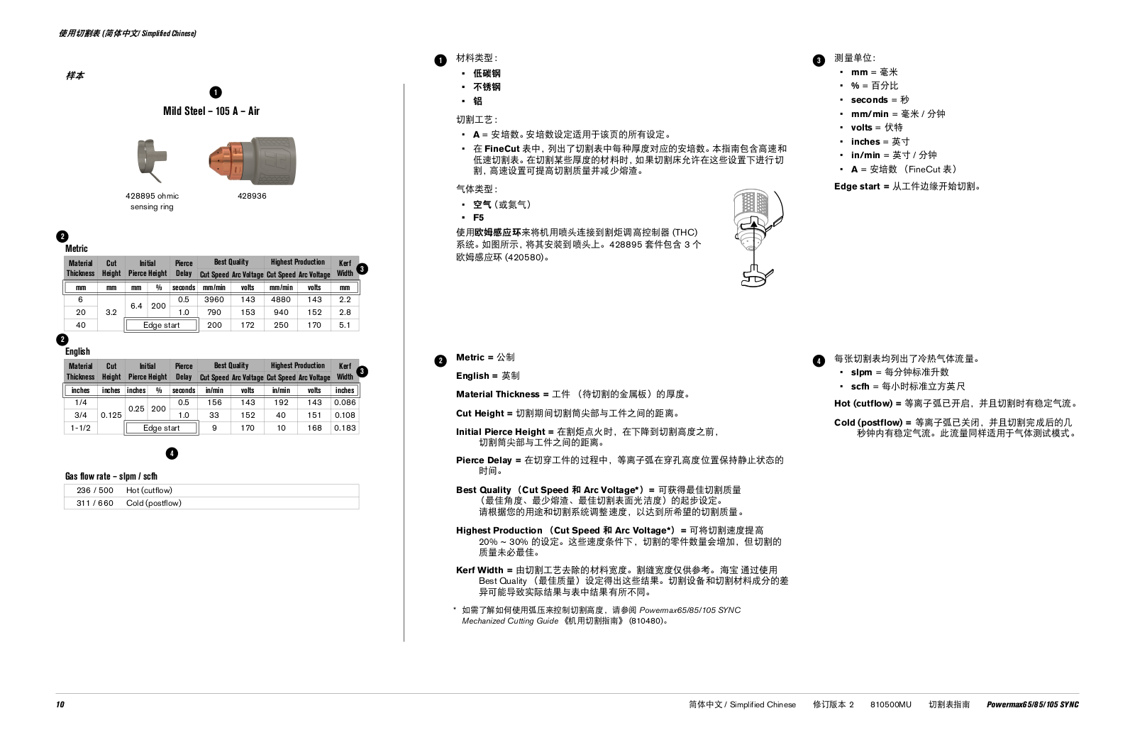


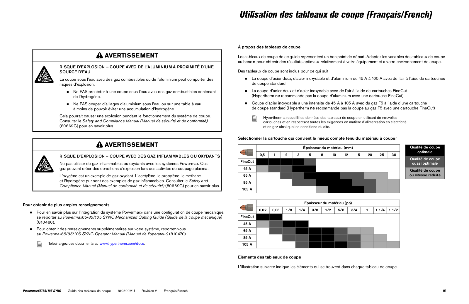


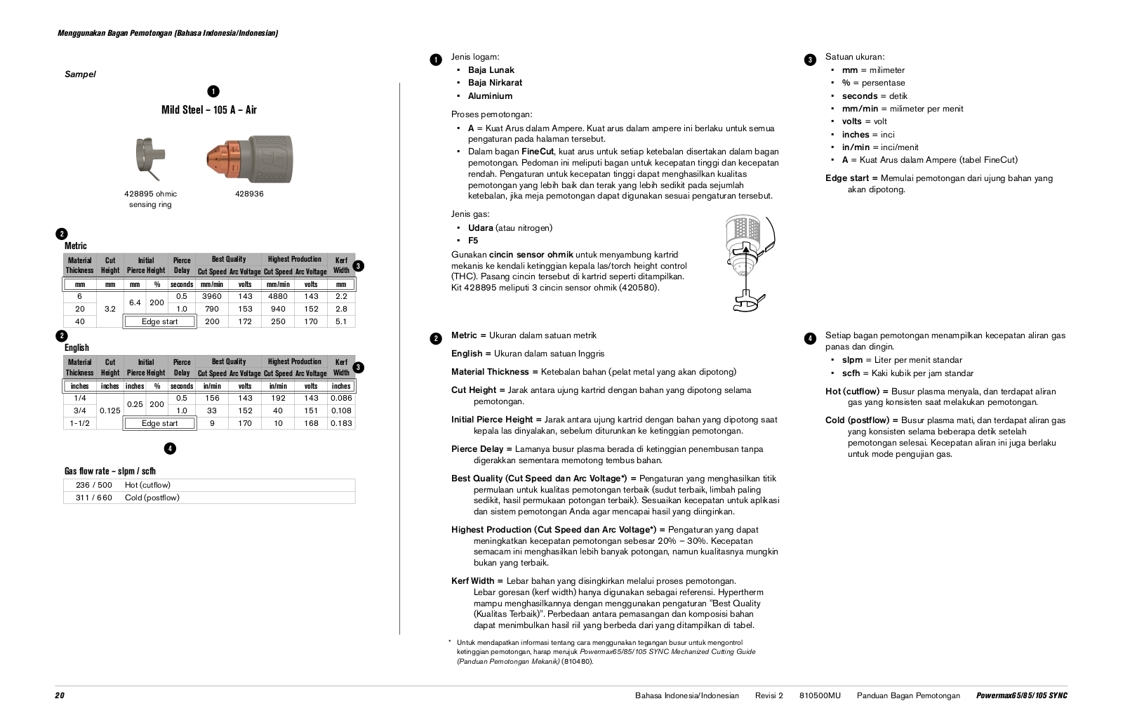


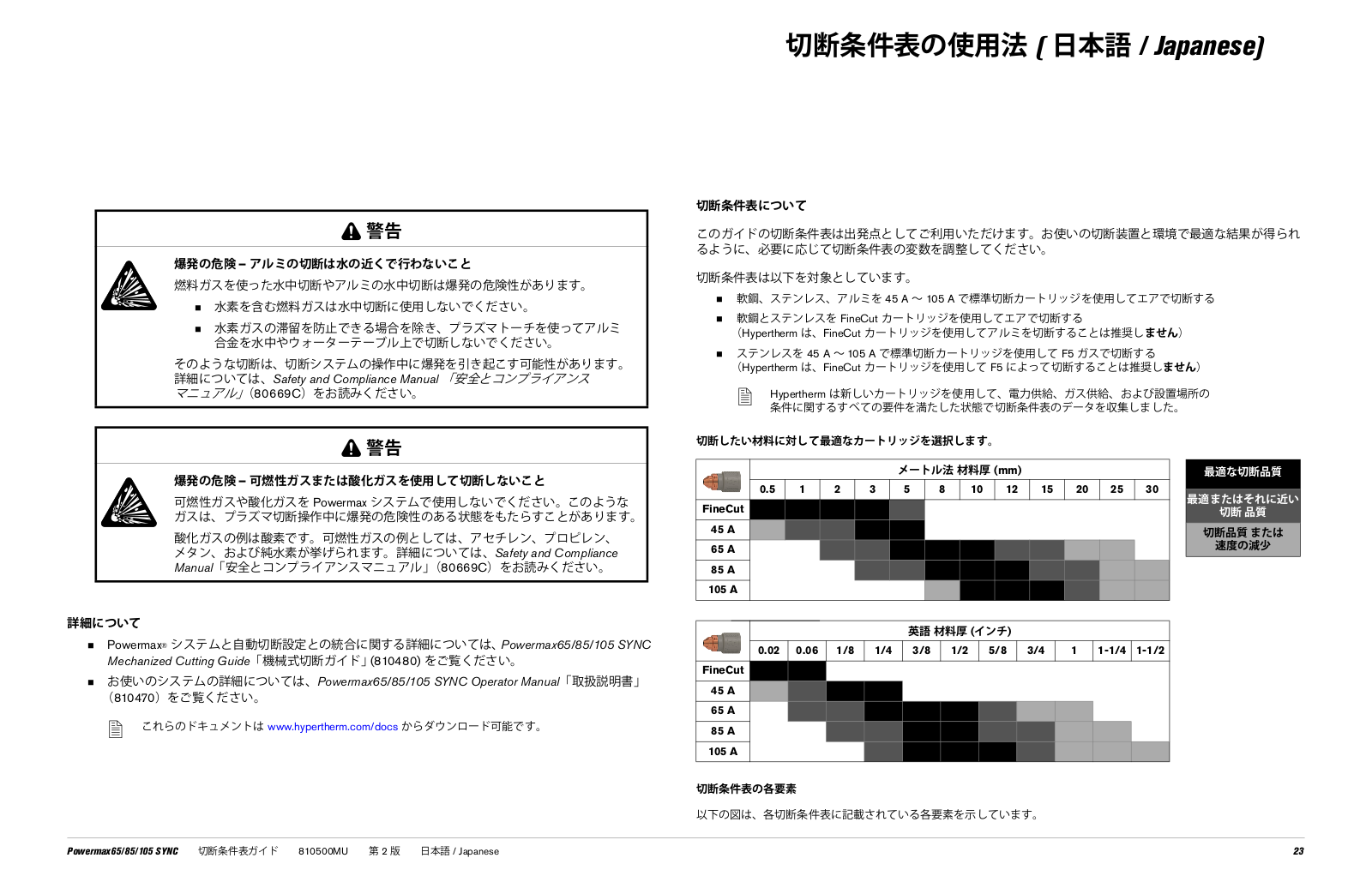


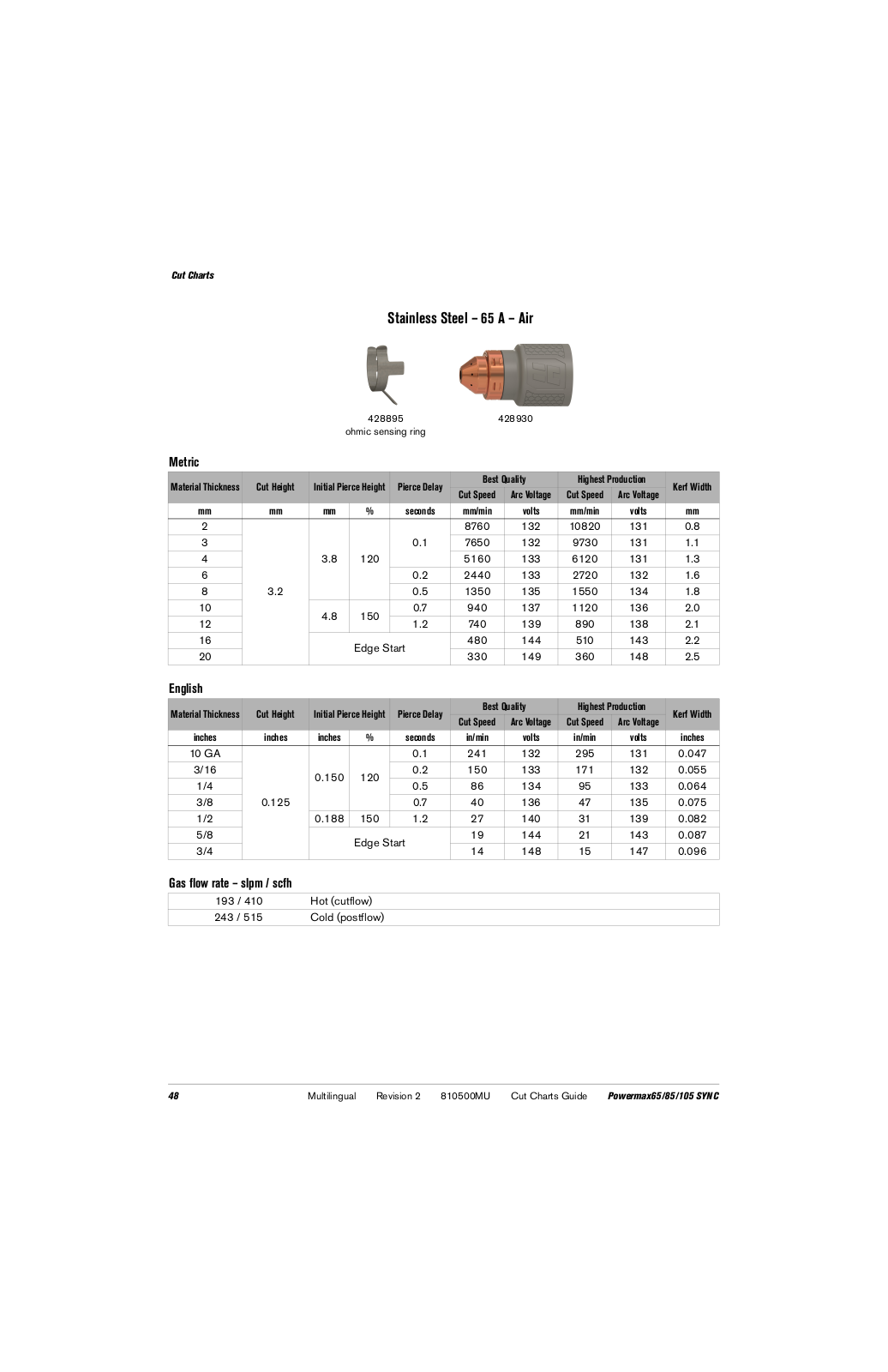


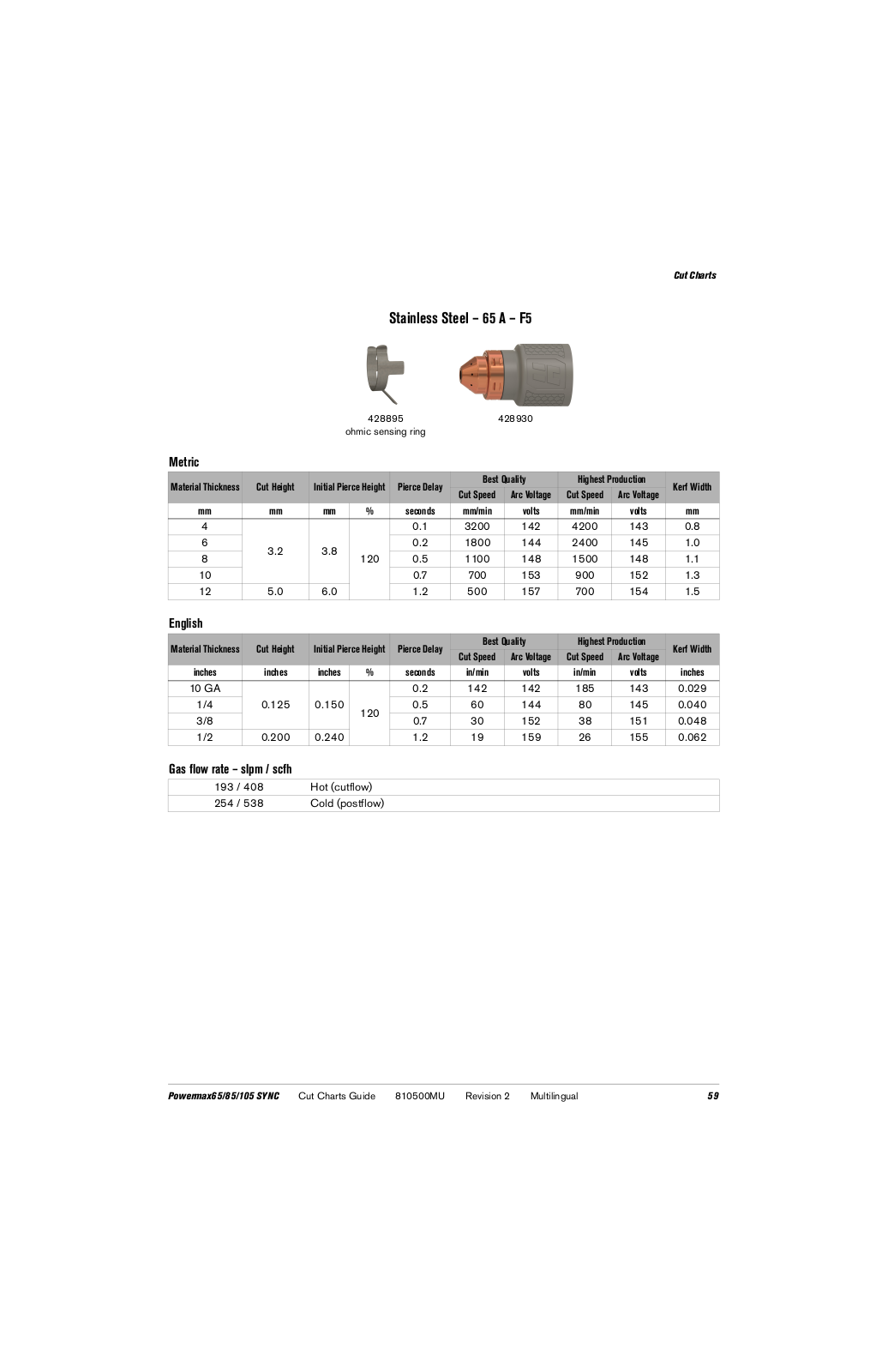

 Loading...