

Page 1

Automation
Hypertherm Automation
5 Technology Drive, Suite 300
W. Lebanon, NH 03784 USA
Phone: 603-298-7970
Fax: 603-298-7977
HYPERTHERM SHAPE CUTTING CONTROL
OPERATOR AND INSTALLATION MANUAL
Software Version 8.0 for Touch Screen CNCs
July 2008
Page 2

D
ISCLAIMER The information in this document is subject to change without notice and should not be
construed as a commitment by Hypertherm Automation. Hypertherm Automation
assumes no responsibility for any errors that appear.
T
RADEMARKS Hypertherm Automation is a wholly owned subsidiary of Hypertherm, Inc.
Command, HT 4400, HD3070 HyDefinition Plasma and HD4070 HyDefinition Plasma
are registered trademarks of Hypertherm, Inc.
FASTLaser is a trademark of Hypertherm, Inc.
EDGE, HyperCAD, HyperNet, HyperNest, Phoenix, and ShapeWizard are registered
trademarks of Hypertherm Automation.
Align, APC, CutPro, Gemini, HPR130, HPR260 HyPerformance Plasma, Mariner,
Nester, Remote Help, Sensor, and Voyager are trademarks of Hypertherm Automation.
HASP is a registered trademark of Aladdin Knowledge Systems Ltd.
Indramat is a trademark of Bosch Rexroth.
Pacific Scientific is a trademark of Danaher Motion.
Pentium and Celeron are registered trademarks of Intel Corporation.
Virus Scan is a registered trademark of McAfee Associates, Inc.
Microsoft, the Microsoft logo, and Windows are registered trademarks of Microsoft
Corporation.
NJWIN is a registered trademark of NJStar Software Corporation.
SERCOS Interface is a trademark of SERCOS North America.
Norton AntiVirus and Norton Ghost are trademarks of Symantec Corporation.
Other trademarks are the property of their respective holders.
C
OPYRIGHT 2008 by Hypertherm Automation. All rights Reserved
Printed in USA
ii
Page 3

Contents
Safety ............................................................................................................................................ 1
Overview ...................................................................................................................................... 9
CutPro Wizard ........................................................................................................................ 9
Align Wizard ........................................................................................................................... 9
Remote Help ........................................................................................................................... 9
ShapeWizard ........................................................................................................................... 9
Teach/Trace ............................................................................................................................. 9
Shape Libraries ..................................................................................................................... 10
Program Upload and Download............................................................................................ 10
SoftMotion ............................................................................................................................ 10
Cutting Options ..................................................................................................................... 10
Programming Features .......................................................................................................... 11
Performance Features............................................................................................................ 12
Installation and Setup Features ............................................................................................. 12
Hardware Specifications ....................................................................................................... 13
Model Numbering System .................................................................................................... 13
Front Panel Layout ................................................................................................................ 14
PC Keyboard Layout ............................................................................................................. 17
Key and Menu Functions ...................................................................................................... 20
Numeric Keypad ................................................................................................................... 22
Help Screen ........................................................................................................................... 22
Main Screen .......................................................................................................................... 23
Shape Manager Screen .......................................................................................................... 26
Files ....................................................................................................................................... 28
Setups Screen ........................................................................................................................ 30
Change Consumable ............................................................................................................. 31
Remote Help .............................................................................................................................. 33
Install Shared View ............................................................................................................... 33
Use Remote Help .................................................................................................................. 34
Setups ......................................................................................................................................... 37
Cutting................................................................................................................................... 37
Process .................................................................................................................................. 43
Oxy Fuel................................................................................................................................ 44
Plasma ................................................................................................................................... 52
HD3070 Auto Gas Interface ................................................................................................. 56
HD4070 and HPR Overview ................................................................................................ 59
FineLine Overview ............................................................................................................... 65
Marker ................................................................................................................................... 71
Laser Overview ..................................................................................................................... 75
Laser Cut Chart Screen ......................................................................................................... 81
Water Jet ............................................................................................................................... 87
Watch .................................................................................................................................... 89
iii
Page 4

Shape Manager.......................................................................................................................... 93
Shape Library ........................................................................................................................ 93
Text Editor ............................................................................................................................ 94
Shape Wizard ........................................................................................................................ 95
Teach Trace ........................................................................................................................... 97
Nester .................................................................................................................................. 102
Manual Nesting ................................................................................................................... 103
Nester Setup ........................................................................................................................ 105
Using Nester........................................................................................................................ 106
HyperNest – CNC Automatic Nesting Software ................................................................ 109
Automatic Nesting Setup .................................................................................................... 110
Using HyperNest – CNC .................................................................................................... 112
HyperCAD .......................................................................................................................... 119
HyperNEST......................................................................................................................... 121
Files........................................................................................................................................... 123
Load from
Disk ................................................................................................................... 123
Resume Last Part Features .................................................................................................. 125
Save to Disk ........................................................................................................................ 126
Download from Host ........................................................................................................... 129
Upload to Host .................................................................................................................... 131
Loading Invalid Files .......................................................................................................... 132
Library Shapes ........................................................................................................................ 135
Rectangle............................................................................................................................. 136
Circle ................................................................................................................................... 138
Triangle ............................................................................................................................... 140
L-Bracket ............................................................................................................................ 142
Trapezoid ............................................................................................................................ 144
Slant Rectangle ................................................................................................................... 146
Gambrel Rectangle .............................................................................................................. 148
Roofed Rectangle ................................................................................................................ 150
4-Sided Polygon .................................................................................................................. 152
5-Sided Polygon .................................................................................................................. 154
Oval ..................................................................................................................................... 156
Circle with Flat Side ........................................................................................................... 158
Circle Slice .......................................................................................................................... 160
Straight Slots ....................................................................................................................... 162
Angled Slots ........................................................................................................................ 164
Horizontal Rip ..................................................................................................................... 166
Vertical Rip ......................................................................................................................... 168
Flange .................................................................................................................................. 170
Circle with Rectangular Hole .............................................................................................. 172
Gusset .................................................................................................................................. 174
8-Sided ................................................................................................................................ 176
Rectangle with Convex Corners ......................................................................................... 178
Rectangle with Concave Corners ........................................................................................ 180
L-Bracket with Elbow Radii ............................................................................................... 182
iv
Page 5

Slant L-Bracket with Elbow Radii ...................................................................................... 184
Flange Slice ......................................................................................................................... 188
Elbow .................................................................................................................................. 190
Flange Repair Ring ............................................................................................................. 192
Rectangle with Rectangular Hole ....................................................................................... 194
Rectangle with Circular Hole .............................................................................................. 196
Rectangle with Circular Hole and Convex Corners ............................................................ 198
Rectangle with Tab ............................................................................................................. 200
Rectangle with Convex Tab ................................................................................................ 202
Rectangle with Notch .......................................................................................................... 204
Concave Rectangle .............................................................................................................. 212
Triangle with Concave Side ................................................................................................ 214
Polygon with Concave Side ................................................................................................ 216
Slant Rectangle with Radius ............................................................................................... 218
Slant Rectangle with Circular Hole .................................................................................... 220
Slant Rectangle with Beveled Corners ............................................................................... 222
Cross ................................................................................................................................... 224
Cross with Circular Hole and Concave Inside Corners ...................................................... 226
4 Sided Convex Rectangle .................................................................................................. 228
4 Sided Concave Rectangle ................................................................................................ 230
Pipe Mount .......................................................................................................................... 232
Bolt Hole Circle .................................................................................................................. 234
Bolt Hole Flange ................................................................................................................. 236
Bolt Hole Rectangle ............................................................................................................ 238
Bolt Hole Rectangle with Convex Corners ......................................................................... 240
Bolt Hole Rectangle with Center Hole ............................................................................... 242
Bolt Hole Rectangle with Center Hole and Convex Corners ............................................. 244
Rounded L-Bracket ............................................................................................................. 246
Horseshoe ............................................................................................................................ 248
Convex Roof Trapezoid with Hole ..................................................................................... 250
Convex Roof Polygon with Hole ........................................................................................ 252
Convex Roof Polygon with Oval Hole and Concave Bottom ............................................ 254
Pulley Cover........................................................................................................................ 256
Paddle Blind ........................................................................................................................ 258
Water Pump Gasket ............................................................................................................ 260
Frame .................................................................................................................................. 262
Pulley .................................................................................................................................. 264
Sprocket .............................................................................................................................. 266
Text ..................................................................................................................................... 268
Test Pattern ......................................................................................................................... 270
Part Options ............................................................................................................................ 271
Repeat ................................................................................................................................. 273
Align ................................................................................................................................... 276
Align Wizard ....................................................................................................................... 276
Manual Part Alignment ....................................................................................................... 277
Automatic Plate Alignment (APA) ..................................................................................... 278
v
Page 6

Cut Operations ........................................................................................................................ 283
CutPro Wizard .................................................................................................................... 283
Cutting in Manual Mode ..................................................................................................... 283
Multitasking ........................................................................................................................ 287
Pause......................................................................................................................................... 289
Change Consumable ........................................................................................................... 295
Manual ..................................................................................................................................... 297
Manual Options ................................................................................................................... 303
Home Axes.......................................................................................................................... 305
Diagnostics ............................................................................................................................... 307
Control Information ............................................................................................................ 307
I/O ....................................................................................................................................... 309
Analog Input Diagnostics ................................................................................................... 312
Serial Port............................................................................................................................ 313
Drives and Motors............................................................................................................... 315
SERCOS Drives and Motors .............................................................................................. 317
Error Messages.................................................................................................................... 320
Norton Ghost Utility ........................................................................................................... 325
Password Setups ...................................................................................................................... 329
Machine............................................................................................................................... 330
SERCOS ............................................................................................................................. 333
Speeds ................................................................................................................................. 336
CBH Speed Setups .............................................................................................................. 339
THC Speed Setups .............................................................................................................. 339
Torch Height Disable .......................................................................................................... 341
Ports .................................................................................................................................... 343
I/O ....................................................................................................................................... 348
Speed Pot and Joystick Overview ....................................................................................... 350
Axes – Transverse or Rail ................................................................................................... 364
Axes -- Dual Gantry ............................................................................................................ 369
Axes -- CBH ....................................................................................................................... 372
Axes -- Rotate ..................................................................................................................... 375
Axes -- Tilt .......................................................................................................................... 376
Axes -- Transverse 2 ........................................................................................................... 377
Station Configuration .......................................................................................................... 378
Special ................................................................................................................................. 385
System Tools – Windows XP ............................................................................................. 391
Phoenix Link............................................................................................................................ 399
Overview ............................................................................................................................. 399
Files ..................................................................................................................................... 400
Settings ................................................................................................................................ 402
Installation........................................................................................................................... 403
Software .............................................................................................................................. 403
Hardware ............................................................................................................................. 407
Operating Phoenix Link ...................................................................................................... 408
Common Errors ................................................................................................................... 408
vi
Page 7

Error Messages.................................................................................................................... 409
Sensor THC ............................................................................................................................. 411
Overview ............................................................................................................................. 411
Cut Setups ........................................................................................................................... 412
Plasma Setups ..................................................................................................................... 413
Marker Setups ..................................................................................................................... 417
Process Watch ..................................................................................................................... 419
Main Cut Screen ................................................................................................................. 420
Sensor THC Setups ............................................................................................................. 421
Sensor THC Axis Setups .................................................................................................... 422
THC Speeds ........................................................................................................................ 424
THC I/O .............................................................................................................................. 425
Command THC ....................................................................................................................... 429
Main Cut Screen ................................................................................................................. 433
Diagnostics .......................................................................................................................... 435
Machine Interface ............................................................................................................... 435
Motion Overview ..................................................................................................................... 437
Closed Loop Servo Control ................................................................................................ 437
Encoders .............................................................................................................................. 438
Encoder Counts and Maximum Machine Speed ................................................................. 440
Motion Tuning Watch Windows ........................................................................................ 445
SERCOS Interface Overview ............................................................................................. 447
ASCII Codes ............................................................................................................................ 449
0BProgram Codes ........................................................................................................................ 451
1BEIA RS-274D ...................................................................................................................... 451
2B2BESSI .................................................................................................................................... 459
3B3BAdvanced Feature Codes ................................................................................................... 463
4BStation Selects ..................................................................................................................... 464
5BAutomatic Torch Spacing ................................................................................................... 465
6BSensor THC Part Program Support ..................................................................................... 468
7BSubparts............................................................................................................................... 469
8BMarker Font Generator ....................................................................................................... 471
9BSerial Messaging ................................................................................................................. 475
Automated Plasma Interface ................................................................................................. 485
HPR and HD4070 Interface ................................................................................................ 485
Cut Charts ........................................................................................................................... 486
Custom Cut Charts .............................................................................................................. 490
Change Consumable ........................................................................................................... 493
HD4070 Diagnostics ........................................................................................................... 494
HPR Diagnostics ................................................................................................................. 495
HD3070 Auto Gas Interface ............................................................................................... 504
FineLine Overview ............................................................................................................. 507
Serial Ports .............................................................................................................................. 515
Control RS-232C DB-9 Pinout ........................................................................................... 515
RS-232C Connections to Host PC with 9-pin D-type connector ........................................ 516
RS-232C Connections to Host PC with 25-pin D-type connector ...................................... 516
vii
Page 8

Automatic DXF Import .......................................................................................................... 517
Overview ............................................................................................................................. 517
Load DXF Files................................................................................................................... 517
Raw DXF Files ................................................................................................................... 518
Prepared DXF Files............................................................................................................. 520
Networking .............................................................................................................................. 523
Network Operating System ................................................................................................. 523
Configuring the Network Interface Card ............................................................................ 523
Connecting the CNC to a Network ..................................................................................... 524
Mapping a Connection to a Network Share ........................................................................ 524
Connecting the CNC to a Workgroup ................................................................................. 527
Hardware Considerations .................................................................................................... 529
MicroEdge ............................................................................................................................... 535
Overview ............................................................................................................................. 535
Keyboard Layout ................................................................................................................ 536
System Requirements.......................................................................................................... 536
Machine Interface ............................................................................................................... 537
I/O Configuration ................................................................................................................ 538
I/O Interface ........................................................................................................................ 539
THC and Joystick Interface ................................................................................................ 544
Calibration........................................................................................................................... 548
Edge Ti ..................................................................................................................................... 549
Overview ............................................................................................................................. 549
Machine Interface ............................................................................................................... 550
I/O Configuration ................................................................................................................ 551
I/O Interface ........................................................................................................................ 552
Lifter Interface .................................................................................................................... 555
Plasma Interface .................................................................................................................. 556
External Interlock................................................................................................................ 557
Voyager III .............................................................................................................................. 561
Overview ............................................................................................................................. 561
Setups .................................................................................................................................. 563
Common Status Messages .................................................................................................. 564
Machine Interface ............................................................................................................... 565
SERCOS to Analog Conversion Card ................................................................................ 570
Mariner .................................................................................................................................... 573
Overview ............................................................................................................................. 573
Touch Screen ...................................................................................................................... 573
THC, Joystick and Speedpots ............................................................................................. 573
AC Input Pinout .................................................................................................................. 574
E-Stop ................................................................................................................................. 574
Diagram Location Din-02 ................................................................................................... 574
SERCOS Motion and I/O.................................................................................................... 574
viii
Page 9

Safety
Product Listings
MicroEdge and Voyager III
Note: This product has been designed and manufactured in accordance with CE and UL Safety
Standards.
UL has successfully tested and listed these products in accordance with the applicable U.S. and
Canadian Safety Standards. File number E178333. Note: Suitable for pollution degree 2
environment only.
This appliance has been successfully tested and listed by CE under the following standards; EN
500081-2 1994, EN 61000-6-2 1999, and EN 55011:1998. Certificate number: Retlif R-3909N
Edge TI
Note: This product has been designed and manufactured in accordance with CE and UL Safety
Standards.
UL has successfully tested and listed these products in accordance with the applicable U.S. and
Canadian Safety Standards. File number E307226.
Additional markings:
1. Use minimum 75° C copper wire only.
2. Use copper conductors only.
3. Suitable for use on a circuit capable of delivering not more than 5000rms symmetrical
amperes, 230 volts maximum.
4. Solid state motor overload protection is not provided on this device.
5. Integral solid state short circuit protection does not provide branch circuit protection.
Branch circuit protection provided by integral LISTED branch circuit protection fuse.
This appliance has been successfully tested and listed by CE under the following standards; EN 5000812 1994, EN 61000-6-2 1999, and EN 55011:1998. Certificate number: Retlif R-3909N
Please contact Hypertherm Automation for further safety listing information.
1
Page 10

2 Safety
RECOGNIZE SAFETY INFORMATION
The symbols shown in this section are used to
identify potential hazards. When you see a safety
symbol in this manual or on your machine, understand
the potential for personal injury, and follow the related
instructions to avoid the hazard.
FOLLOW SAFETY INSTRUCTIONS
Read carefully all safety messages in this manual and
safety labels on your machine.
• Keep the safety labels on your machine in good
condition. Replace missing or damaged labels
immediately.
• Learn how to operate the machine and how to use
the controls properly. Do not let anyone operate it
without instruction.
• Keep your machine in proper working condition.
Unauthorized modifications to the machine may
affect safety and machine service life.
DANGER WARNING CAUTION
A signal word DANGER or WARNING is used with a
safety symbol. DANGER identifies the most serious
hazards.
• DANGER and WARNING safety labels are located
on your machine near specific hazards.
• WARNING safety messages precede related
instruc tions in this manual that may result in injury
or death if not followed correctly.
• CAUTION safety messages precede related
instructions in this manual that may result in
damage to equipment if not followed correctly.
Fire Prevention
• Be sure the area is safe before doing any cutting.
Keep a fire extinguisher nearby.
• Remove all flammables within 35 feet (10 m) of the
cutting area.
• Quench hot metal or allow it to cool before handling
or before letting it touch combustible materials.
• Never cut containers with potentially flammable
materials inside – they must be emptied and
properly cleaned first.
• Ventilate potentially flammable atmospheres before
cutting.
• When cutting with oxygen as the plasma gas, an
exhaust ventilation system is required.
Explosion Prevention
• Do not use the plasma system if explosive dust or
vapors may be present.
• Do not cut pressurized cylinders, pipes, or any
closed container.
• Do not cut containers that have held combustible
materials.
CUTTING CAN CAUSE FIRE OR EXPLOSION
WARNING
Explosion Hazard
Argon-Hydrogen and Methane
Hydrogen and methane are flammable gases that
present an explosion hazard. Keep flames away from
cylinders and hoses that contain methane or hydrogen
mixtures. Keep flames and sparks away from the torch
when using methane or argon-hydrogen plasma.
WARNING
Hydrogen Detonation with Aluminum Cutting
• When cutting aluminum underwater, or with the
water touching the underside of the aluminum, free
hydrogen gas may collect under the workpiece and
detonate during plasma cutting operations.
• Install an aeration manifold on the floor of the water
table to eliminate the possibility of hydrogen
detonation. Refer to the Appendix section of this
manual for aeration manifold details.
Page 11

Safety 3
Touching live electrical parts can cause a fatal shock
or severe burn.
• Operating the plasma system completes an
electrical circuit between the torch and the
workpiece. The workpiece and anything touching
the workpiece are part of the electrical circuit.
• Never touch the torch body, workpiece or the water
in a water table when the plasma system is
operating.
Electric Shock Prevention
All Hypertherm plasma systems use high voltage
in the cutting process (200 to 400 VDC are
common). Take the following precautions when
operating this system:
• Wear insulated gloves and boots, and keep your
body and clothing dry.
• Do not stand, sit or lie on – or touch – any wet
surface when using the plasma system.
• Insulate yourself from work and ground using dry
insulating mats or covers big enough to prevent any
physical contact with the work or ground. If you must
work in or near a damp area, use extreme caution.
• Provide a disconnect switch close to the power
supply with properly sized fuses. This switch allows
the operator to turn off the power supply quickly in
an emergency situation.
• When using a water table, be sure that it is correctly
connected to earth ground.
ELECTRIC SHOCK CAN KILL
• Install and ground this equipment according to the
instruction manual and in accordance with national
and local codes.
• Inspect the input power cord frequently for damage
or cracking of the cover. Replace a damaged power
cord immediately. Bare wiring can kill.
• Inspect and replace any worn or damaged torch
leads.
• Do not pick up the workpiece, including the waste
cutoff, while you cut. Leave the workpiece in place
or on the workbench with the work cable attached
during the cutting process.
• Before checking, cleaning or changing torch parts,
disconnect the main power or unplug the power
supply.
• Never bypass or shortcut the safety interlocks.
• Before removing any power supply or system
enclosure cover, disconnect electrical input power.
Wait 5 minutes after disconnecting the main power
to allow capacitors to discharge.
• Never operate the plasma system unless the power
supply covers are in place. Exposed power supply
connections present a severe electrical hazard.
• When making input connections, attach proper
grounding conductor first.
• Each Hypertherm plasma system is designed to be
used only with specific Hypertherm torches. Do not
substitute other torches which could overheat and
present a safety hazard.
Use proper precautions when handling printed
circuit boards.
STATIC ELECTRICITY CAN DAMAGE CIRCUIT BOARDS
• Store PC boards in anti-static containers.
• Wear a grounded wrist strap when handling
PC boards.
Page 12

4 Safety
The plasma arc by itself is the heat source used for
cutting. Accordingly, although the plasma arc has not
been identified as a source of toxic fumes, the
material being cut can be a source of toxic fumes or
gases that deplete oxygen.
Fumes produced vary depending on the metal that is
cut. Metals that may release toxic fumes include, but
are not limited to, stainless steel, carbon steel, zinc
(galvanized), and copper.
In some cases, the metal may be coated with a
substance that could release toxic fumes. Toxic
coatings include, but are not limited to, lead (in some
paints), cadmium (in some paints and fillers), and
beryllium.
Gases produced by plasma cutting vary based on the
material to be cut and the method of cutting, but may
include ozone, oxides of nitrogen, hexavalent
chromium, hydrogen, and other substances if such
are contained in or released by the material being cut.
Caution should be taken to minimize exposure to
fumes produced by any industrial process. Depending
upon the chemical composition and concentration of
the fumes (as well as other factors, such as
ventilation), there may be a risk of physical illness,
such as birth defects or cancer.
It is the responsibility of the equipment and site owner
to test the air quality in the area where the equipment
is used and to ensure that the air quality in the
workplace meets all local and national standards
and regulations.
TOXIC FUMES CAN CAUSE INJURY OR DEATH
The air quality level in any relevant workplace
depends on site-specific variables such as:
• Table design (wet, dry, underwater).
• Material composition, surface finish, and
composition of coatings.
• Volume of material removed.
• Duration of cutting or gouging.
• Size, air volume, ventilation and filtration of the
work area.
• Personal protective equipment.
• Number of welding and cutting systems in
operation.
• Other site processes that may produce fumes.
If the workplace must conform to national or local
regulations, only monitoring or testing done at the site
can determine whether the site is above or below
allowable levels.
To reduce the risk of exposure to fumes:
• Remove all coatings and solvents from the metal
before cutting.
• Use local exhaust ventilation to remove fumes from
the air.
• Do not inhale fumes. Wear an air-supplied
respirator when cutting any metal coated with,
containing, or suspected to contain toxic elements.
• Assure that those using welding or cutting
equipment, as well as air-supplied respiration
devices, are qualified and trained in the proper use
of such equipment.
• Never cut containers with potentially toxic materials
inside. Empty and properly clean the container first.
• Monitor or test the air quality at the site as needed.
• Consult with a local expert to implement a site plan
to ensure safe air quality.
Page 13

Safety 5
Instant-On Torches
Plasma arc comes on immediately when the torch
switch is activated.
A PLASMA ARC CAN CAUSE INJURY AND BURNS
The plasma arc will cut quickly through gloves and
skin.
• Keep away from the torch tip.
• Do not hold metal near the cutting path.
• Never point the torch toward yourself or others.
Eye Protection Plasma arc rays produce intense
visible and invisible (ultraviolet and infrared) rays that
can burn eyes and skin.
• Use eye protection in accordance with applicable
national or local codes.
• Wear eye protection (safety glasses or goggles with
side shields, and a welding helmet) with appropriate
lens shading to protect your eyes from the arcʼs
ultraviolet and infrared rays.
Lens Shade
Arc Current AWS (USA) ISO 4850
Up to 100 A No. 8 No. 11
100-200 A No. 10 No. 11-12
200-400 A No. 12 No. 13
Over 400 A No. 14 No. 14
ARC RAYS CAN BURN EYES AND SKIN
Skin Protection Wear protective clothing to protect
against burns caused by ultraviolet light, sparks and
hot metal.
• Gauntlet gloves, safety shoes and hat.
• Flame-retardant clothing to cover all exposed areas.
• Cuffless trousers to prevent entry of sparks and
slag.
• Remove any combustibles, such as a butane lighter
or matches, from your pockets before cutting.
Cutting Area Prepare the cutting area to reduce
reflection and transmission of ultraviolet light:
• Paint walls and other surfaces with dark colors to
reduce reflection.
• Use protective screens or barriers to protect others
from flash and glare.
• Warn others not to watch the arc. Use placards or
signs.
Work Cable Attach the work cable securely to the
workpiece or the work table with good metal-to-metal
contact. Do not connect it to the piece that will fall
away when the cut is complete.
Work Table Connect the work table to an earth
ground, in accordance with appropriate national or
local electrical codes.
GROUNDING SAFETY
Input Power
• Be sure to connect the power cord ground wire to
the ground in the disconnect box.
• If installation of the plasma system involves
connecting the power cord to the power supply, be
sure to connect the power cord ground wire
properly.
• Place the power cord's ground wire on the stud first,
then place any other ground wires on top of the
power cord ground. Fasten the retaining nut tightly.
• Tighten all electrical connections to avoid excessive
heating.
Page 14

6 Safety
ADDITIONAL SAFETY INFORMATION
1. ANSI Standard Z49.1,
Safety in Welding and Cutting,
American
Welding Society, 550 LeJeune Road
P.O. Box 351020, Miami, FL 33135
2. ANSI Standard Z49.2,
Fire Prevention in the Use of Cutting and
Welding Processes,
American National Standards Institute
1430 Broadway, New York, NY 10018
3. ANSI Standard Z87.1,
Safe Practices for Occupation and
Educational Eye and Face Protection,
American National
Standards Institute, 1430 Broadway, New York, NY 10018
4. AWS F4.1,
Recommended Safe Practices for the Preparation for
Welding and Cutting of Containers and Piping That Have Held
Hazardous Substances,
American Welding Society
550 LeJeune Road, P.O. Box 351040, Miami, FL 33135
5. AWS F5.2,
Recommended Safe Practices for Plasma Arc
Cutting,
American Welding Society
550 LeJeune Road, P.O. Box 351040, Miami, FL 33135
6. CGA Pamphlet P-1,
Safe Handling of Compressed Gases in
Cylinders,
Compressed Gas Association
1235 Jefferson Davis Highway, Arlington, VA 22202
7. CSA Standard W117.2,
Code for Safety in Welding and Cutting,
Canadian Standards Association Standard Sales
178 Rexdale Boulevard, Rexdale, Ontario M9W 1R3, Canada
8. NFPA Standard 51B,
Cutting and Welding Processes,
National
Fire Protection Association
470 Atlantic Avenue, Boston, MA 02210
9. NFPA Standard 70–1978,
National Electrical Code,
National Fire
Protection Association, 470 Atlantic Avenue, Boston, MA 02210
10. OSHA,
Safety and Health Standards,
29FR 1910
U.S. Government Printing Office, Washington, D.C. 20402
• Never lubricate cylinder valves or regulators with oil
or grease.
• Use only correct gas cylinders, regulators, hoses
and fittings designed for the specific application.
• Maintain all compressed gas equipment and
associated parts in good condition.
• Label and color-code all gas hoses to identify the
type of gas in each hose. Consult applicable
national or local codes.
GAS CYLINDERS CAN
EXPLODE IF DAMAGED
COMPRESSED GAS EQUIPMENT SAFETY
Gas cylinders contain gas under high pressure. If
damaged, a cylinder can explode.
• Handle and use compressed gas cylinders in
accordance with applicable national or local codes.
• Never use a cylinder that is not upright and secured
in place.
• Keep the protective cap in place over valve except
when the cylinder is in use or connected for use.
• Never allow electrical contact between the plasma
arc and a cylinder.
• Never expose cylinders to excessive heat, sparks,
slag or open flame.
• Never use a hammer, wrench or other tool to open
a stuck cylinder valve.
Prolonged exposure to noise from cutting or gouging
can damage hearing.
• Use approved ear protection when using plasma
system.
• Warn others nearby about the noise hazard.
NOISE CAN DAMAGE HEARING
Pacemaker and hearing aid operation can be affected
by magnetic fields from high currents.
Pacemaker and hearing aid wearers should consult a
doctor before going near any plasma arc cutting and
gouging operations.
To reduce magnetic field hazards:
• Keep both the work cable and the torch lead to one
side, away from your body.
• Route the torch leads as close as possible to the
work cable.
• Do not wrap or drape the torch lead or work cable
around your body.
• Keep as far away from the power supply as
possible.
PACEMAKER AND HEARING
AID OPERATION
A PLASMA ARC CAN
DAMAGE FROZEN PIPES
Frozen pipes may be damaged or can burst if you
attempt to thaw them with a plasma torch.
Page 15

Safety 7
WARNING LABEL
This warning label is affixed to some power supplies. It is
important that the operator and maintenance technician
understand the intent of these warning symbols as described.
The numbered text corresponds to the numbered boxes on
the label.
1. Cutting sparks can cause explosion or fire.
1.1 Keep flammables away from cutting.
1.2 Keep a fire extinguisher nearby, and have
a watchperson ready to use it.
1.3 Do not cut on any closed containers.
2. The plasma arc can cause injury and
burns.
2.1 Turn off power before disassembling torch.
2.2 Do not hold the material near cutting path.
2.3 Wear complete body protection.
3. Electric shock from torch or wiring can kill.
Protect yourself from electric shock.
3.1 Wear insulating gloves. Do not wear wet or
damaged gloves.
3.2 Insulate yourself from work and ground.
3.3 Disconnect input plug or power before
working on machine.
4. Breathing cutting fumes can be hazardous
to your health.
4.1 Keep your head out of the fumes.
4.2 Use forced ventilation or local exhaust to
remove the fumes.
4.3 Use ventilating fan to remove the fumes.
5. Arc rays can burn eyes and injure skin.
5.1 Wear hat and safety glasses. Use ear
protection and button shirt collar. Use
welding helmet with correct shade of filter.
Wear complete body protection.
6. Become trained and read the instructions
before working on the machine or cutting.
7. Do not remove or paint over (cover)
warning labels.
www.hypertherm.com/weee
110647 Rev. A
Page 16

8 Safety
Page 17

Overview
The following sections highlight the features of the Hypertherm Automation CNC and version
8.0 of the Phoenix® software.
CutPro Wizard
The CutPro™ wizard is an interactive tool that simplifies the steps of cutting a part. The CutPro
wizard helps you:
• Load a part program
• Select a cut process
• Align a plate and adjust for skew
• Set scrap clearance
• Select cut mode
• Start the cut directly from the wizard or by pressing the green Start button on the console
The wizard opens automatically from the Main screen after 10 seconds. Automatic activation
can be disabled on the Special password setup screen. However, the wizard is always
accessible by pressing the CutPro Wizard soft key on the Main screen.
Align Wizard
The Align™ wizard is an interactive tool that guides you through the process of aligning a plate
and adjusting for a skewed plate. This wizard can be accessed from the CutPro Wizard or from
the Align screen.
Remote Help
The Remote Help™ facility is an easy-to-use and reliable means of remotely connecting the
Hypertherm Automation CNC to up to 15 users for:
• Observing an operator at the machine
• Reviewing settings and software configurations
• Transferring setup files, part programs, software updates, etc.
• Performing HPR diagnostics
• Training users
ShapeWizard
The ShapeWizard
on the internal hard disk present in the control.
®
tool allows you to graphically create simple part programs and store them
Teach/Trace
9
Page 18

Overview
If your system is configured with a tracing head, you can use the control to digitize almost any
pattern, store it on the internal hard disk, and further customize the program with ShapeWizard.
The control has both smart-arc and smart-line translators to provide you with optimum program
resolution.
Shape Libraries
Graphically select the desired shape from the parts library. Then you simply add the dimensions
you want, and the scaled part, with your entered dimensions, will be displayed. There is even a
Help Icon to step you through the data entry.
Program Upload and Download
Communication is an integral part of today’s fabricating shop. All part programs that have
been entered in the control can be uploaded to a remote computer or file server with an
integrated RS-232C/ RS-422 communications link. CAD generated programs can be
downloaded at baud rates of up to 115K baud and visually previewed on the color LCD display.
Visual representation of part programs, along with full alpha-numeric file name support, gives
you the flexibility to manage your data as you see fit. Use of the optional Network Card allows
us to bring the latest in communication technology for increased speed and productivity to your
shape cutting controller. Additionally, built-in Control monitoring features allow current
operational status to be displayed at the host Link screen.
SoftMotion
SoftMotion is a proprietary data buffer and interrupt structure that allows the control to generate
all of its motion control algorithms from the main Pentium® Processor. This architecture allows
SoftMotion to tightly couple the motion control and I/O logic to the operator interface.
Cutting Options
Flexibility in your cutting operation is the key to success. The control comes standard with the
following cutting functions to help you optimize material and plate usage. These functions
work on any program. After selecting one of these functions, the new part will be graphically
displayed.
Mirror function
The mirror function can be used to create a mirror image of the part along either the X or Yaxis.
Rotate function
The rotate function can be used to rotate the current part.
Scale function
The scale function can be used to increase or decrease the current part by a programmed ratio.
Repeat function
10
Page 19

Overview
The repeat function duplicates the part shape in either a straight, staggered or nested grid
patterns.
Programming Features
• English and metric operation for worldwide use. Each axis can have its own encoder-to-
unit edge rate.
• Dynamic kerf compensation with programmable kerf value.
• Automatic corner and plate alignment with programmable scrap clearance.
• Shape Repeat with three grid patterns (straight, stagger, and nested) allows fast cutting of
multiple pieces.
• Part mirroring in both X and Y axes.
• Part rotation.
• Scaling allows quick part resizing to original size.
• Virtually no limit to the number of program names or work file folders that can be stored on
the internal hard disk drive.
• Punch or powder marker control with twelve programmable offsets.
• Choice of industry-standard EIA RS-274D or ISO 6582 ESSI part programming languages.
Manual Data Input (MDI)
• Full screen ASCII text editor.
• Allows writing, editing, and graphical review of part programs at the machine.
Communications Link
• Preview Mode allows machine operator to graphically review and select programs for
download.
• Download part programs from CAD system, remote host computer, or other storage device
via built-in RS-232C/ RS-422 port.
• Can accept EIA RS-274D or ESSI part programs.
• Baud Rates of up to 115K Baud. Communication baud rates of 230K are obtainable using
the communication link software provided with the control.
• Optional network card for connecting directly to a PC Network for part file allocation.
Graphical program display
• Visually display any part program.
• Display of real-time position and I/O information.
• Display of actual cut path while cutting.
Built-in Parametric Shape Library
• Contains 68 commonly used shapes.
• Simple Graphical prompts for entering all part dimensions.
11
Page 20

Overview
Teach/Trace
• Smart-arc and Smart-Line algorithms for optimum program size and contouring
smoothness.
• Converts your existing optical tracer templates to EIA RS-274D programs, and stored on
the internal hard disk drive.
• Automatic part closure detection.
• Allows multiple pierce points, lead-ins, lead-outs, and rapid traverse segments.
• Upload taught part programs to CAD system, remote host computer, or other storage
device.
• Requires a separate optical tracer control system.
Performance Features
• Digital servo positioning control for any cutting machine. An optional SERCOS Interface
allows expansion of motion axes and distributed I/O.
• Control dynamic accuracy of 0.002 inch (0.051 mm) with 1000 edge/inch encoders.
• Programmable cut speeds up to 3000 IPM (76,200 mmpm).
• Variable segment length look-ahead for optimum contouring performance.
• Automatic corner slowdown and torch height disable for clean, sharp corners.
• Speed Increase/Decrease buttons for optimizing machine cut speed.
• Automatic Plate and Corner Alignment corrects for skewed plates.
• Complete cut-loss recovery with backup and forward along path, off-path re-pierce and
return-to-path, and move pattern functions.
• Rip Mode for straight-line cutting. Jog control cutting.
• Punch, powder or Plasma marker capability.
• Manual jog control with position read-out for positioning torches.
• Nester™ and optional HyperNest
productivity and increased plate utilization.
• Automated Torch Spacing feature to position torch station spacing automatically through
the part program for standard and mirrored multi-torch cutting.
• Rush Job Interrupt and Automated Power Loss Recovery features.
®
– CNC Automatic Nesting features for increased
Installation and Setup Features
• Selectable axis orientation for compatibility with all cutting machines.
• Built in oxy-fuel interface with programmable pre-heat time, ignition, and creep speed.
• Built in plasma interface with programmable purge time, ignition time, arc-off delay time,
and arc-transferred feedback.
• Built in Laser interface with programmable shutter time, power ramp time and pierce time.
• Built in Water Jet interface with programmable abrasive output and pierce time.
12
Page 21

Overview
• Programmable servo gains, speeds, Watch Window, machine parameters, and com-
munication parameters for flexible application.
• Interfaces easily to most optical tracing systems for integrated control.
• Complete built-in diagnostics for checkout and test.
Hardware Specifications
• 15” TFT Touch Screen with 1024 x 768 resolution.
• ≥60Gbyte hard disk
• ≥1.3 GHz Processor.
• 512 Mbytes of RAM.
• Up to 96 lines of interface signals for cutting and motion logic (gas control, tracing system,
markers, homing, etc.) depending on I/O configuration. An optional SERCOS Interface™
allows expansion of I/O configuration.
• Industrial grade enclosure and keypad designed to minimize RFI/EMI interference.
• Surface mount printed circuit board technology.
• Two axes optically isolated ±10VDC drive outputs and incremental encoder inputs which
are expandable to 6 axes of motion. Up to twelve axes of motion and 1024 I/O available
with optional SERCOS Interface. Optional axes available for dual gantry, dual transverse,
contoured bevel head, two rotate, two tilt angle and eight Sensor™ THC applications..
• +5VDC single ended or differential encoder inputs.
• Optically isolated serial ports with programmable baud rates to 115 K baud.
Communication baud rates of 230K are obtainable using the communication link software
provided with the control. Optional Network Card for connecting directly to a PC Network.
• Universal power input (100-240 VAC; 47-63Hz). Individual models may vary. Refer to
machine interface information for details.
• Operating environment: 0 to 50°C (32 to 122°F); 95% relative humidity (non-condensing).
• An optional Chiller for Mariner style controls is available.
Model Numbering System
The control is available with the following hardware and software configurations. Features and
control configuration options in software are based on the I/O configuration of the control.
Generally, the information presented in this guide is based on the I/O configuration as outlined
below. Please refer to your control I/O configuration for available features and product
information. The specific configuration is determined by the Model Number, as shown below:
13
Page 22

Overview
H
Axis Configuration
2 = 2 Servo Axes
3 = 3 Servo Axes
4 = 4 Servo Axes
5 = 5 Servo Axes
6 = 6 Servo Axes
7 = 7 Servo Axes
8 = 8 Servo Axes
9 = 9 Servo Axes
A = 10 Servo Axes
B = 11 Servo Axes
C = 12 Servo Axes
S = Sercos
I / O Configuration
B = Burny 3 / 5
M = MicroPath
P = PicoPath
V = Voyager
S = Sercos
D = Edge Ti - DC amps
Power Supplies
0 = Standard Logic Supply
2 = Standard Logic Supply &
Auxiliary Supply with
+5, +/-12 & +24 vdc
Pointing Device
0 = None
1 = Industrial Mouse
LCD Type
X = None
0 = 10.4" Dual Scan DSTN
1 = 10.4" Active Matrix TFT
2 = 15" Active Matrix TFT
3 = 15" Touch Screen
4 = 12.1" Active Matrix TFT
-
Memory
0 = 16 MBytes
1 = 32 MBytes
2 = 64 MBytes
3 = 128 MBytes
4 = 256 MBytes
5 = 512 MBytes
--
Operating System
0 = Windows 95 / 98
1 = Windows NT
2 = Windows XP
APC
0 = None
1 = Laser
2 = Plasma
THC
0 = None
1 = 1 THC
2 = 2 THC's
Speed Pots
0 = None
1 = 1 Speed Pot
2 = 2 Speed Pots
Joystick
0 = None
1 = Joystick
Backup Hard Drive
0 = None
1 = Installed
Processor
0 = 166 MHz
1 = 200 MHz
2 = 266 MHz
3 = 433 MHz
4 = 566 MHz
5 = 1.2 GHz
6 = 2.4 GHz
7 = 3.06 GHz
8 = 1.3 GHz M
Front Panel Layout
This software is designed specifically for 15” TFT Touch Screen operation with 1024 x 768 or
higher resolution and is used on all CNC models. Individual man machine interface (MMI) and
front panels may vary.
Power Switch
Hypertherm Automation controls are equipped with a momentary contact power switch. Press
briefly and release for controlled power on and power off the control. Pressing the power
switch for 10 seconds will force a hard system shutdown of Windows and the control.
Generally, a hard shutdown is not recommended.
Touch Screen
14
Page 23

Overview
The touch screen software interface allows direct key input on the screen through the use of
check boxes, radial boxes, drop down selections and data input. Data input boxes will
automatically display a numeric or alphanumeric keypad depending on data type.
Front Panel (selected models)
ICON Legend
Emergency Stop
Start
Stop
Forward and Backward on Path
Torch Up / Down
Manual
Speed Pot (Manual Feedrate)
Front Panel Keypad (Voyager III model)
The yellow key labeled with a question mark (?) is for online documentation and help. Simply
press this key at any time and this document will be displayed.
The keys to the lower right of the front panel comprise the alpha numeric keypad, which is used
for entering data. To the far left are keys which control manual motion and cursor location
during data input. These include the MANUAL key (for Manual Mode jogs) and the eight
arrow keys (for jog and cursor direction).
The two keys in the center of the keypad are for program start and stop.
15
Page 24

Overview
The two keys to the right of the yellow help key are for Forward on Path and Backup on Path
while in the Pause screen.
Key Functions
The alpha–numeric keypad is used to enter numeric data or
text. To enter a number, simply press the key. To enter a
word, press and hold the matching colored shift key (up arrow)
while pressing the desired letter key. The + (plus) and –
(minus) keys are used to add and delete features at selection
and check boxes.
An alternate (ALT) soft key indicates that more
soft keys and features are available by pressing
this soft key on screen.
When the alternate soft key is displayed, the
purple shift can also be used to view additional
soft keys.
These keys activate jogging using the arrow keys when in the manual
mode. Manual key functions (indicated in green) are available at the
Manual, Pause and Align Screens. This keypad is also used for
navigating through a multi-variable dialog box (indicated in yellow).
The Prev/Next buttons are used to move through the field boxes, Page
Up/Down is used to scroll and the arrow keys are used to select items
in a dialog box.
16
Page 25

Pressing the space key inserts a space into the current data entry field. The space key is also
used to toggle between fixed logic settings ( i.e. setups - preheat sense input open/closed ).
The space key may also be used to add and delete features at selection and check boxes.
Deletes the current character in the data entry field and backs up one position in the field.
Located above the Back Space key are the * and ? characters which are used as wild cards
to search for files.
Can be pressed at any time (except during cut) to return to the previous menu without
saving any changes. Located above the Cancel key are the \ and : characters which are
used for mapping network drives.
Causes the last number entered/toggled to be accepted. Located above the enter key are
the < and > characters which are used for mapping network drives.
PC Keyboard Layout
Overview
Available as standard on selected models but may be added to all controls.
17
Page 26

Overview
Keyboard Functions
Function Keys F1-F8 are equivalent to the soft keys on the display screen.
Function Key F9 is equivalent to the START key.
Function Key F10 and Pause Key are equivalent to the STOP key.
Function Key F11 is equivalent to the MANUAL MODE key.
Function Key F12 is equivalent to the HELP key.
Arrow direction keys are used for manual motion.
The HOME key is equivalent to the PREV field key.
The END key is equivalent to the NEXT field key.
The [ key is equivalent to the purple arrow shift key.
The ] key is equivalent to the blue arrow shift key.
The Esc key is equivalent to the CANCEL key.
To exit the control software press Alt F4. Warning: This will terminate the current application.
To switch between applications press Alt Tab. Warning: The selected application window to be
on top of the desktop and may cover or hide the control software application window.
Operation Summary
The programming and operation of the control is menu-driven. The following diagram shows
the Screen Hierarchy for the menu structure.
The menu that appears in the display when the unit is first turned on is referred to throughout
this manual as the Main Menu. All other menus and functions are accessed at some level under
Main Menu, or else appear as part of a special operational sequence, such as when the cutting
process is interrupted during the middle of a part.
18
Page 27

Overview
The OK and CANCEL keys have special functions in relation to the menu structure. The OK
soft key returns to the menu from which the present selection was entered and retains any
changes that were made. The CANCEL key returns to the menu from which it was entered and
deletes/discards any changes that were made. There are, however, some operations during
which CANCEL is not active.
Screen Hierarchy
Main Screen
Cut Chart
Load from Disk
Save to Disk
Save Log to Disk
Download from Host
Upload to Host
Setups
Cut Types Password 1Diagnostics
Oxy Fuel
Timing Diagram
Water Jet
Timing Diagram
Plasma
Timing Diagram
Cut Chart
Marker
Timing Diagram
Cut Chart
Laser
Timing Diagram
Cut Chart
Process Monitoring
Change Consumable
Manual
Control Information
I / O
Oscilloscope
Serial Port
Drives and Motors
Plasma System
Manual Options
Manual Options
Home Axes
Inputs
Outputs
Analog Inputs
Inputs
Outputs
Supply Information
Part OptionsFiles
Repeat
Align
Manual Options
Speeds
Link
I/O
Sercos
Axes
Transverse
Rail
Dual Gantry
CBH
Tilt
Rotate
THC
Lens
Cut
Pause
Change Consumable
Manual Options
Cutting
WatchMachine
Password 3
Station Configuration
Password 2
System Tools
Backup Hard Drive
Scan Hard Disk
Defrag Hard Disk
Format Floppy Disk
Network Tools
Remote Assistant
Shape Manager
Shape Library
Simple Shape
View Text
Part Options
Repeat
Align
Manual Options
Nester
Nester Setups
Load from Disk
Download from Host
Shape Library
Simple Shape
Shape Wizard
Part Options
Repeat
Align
Manual Options
19
Text Editor
Teach Trace
HyperCAD
HyperNest
Page 28

Overview
Key and Menu Functions
The following is a short form description of all menu functions in the control. This is only a
brief description of each function. Please consult the subsequent manual sections for more
complete information on operational usage of specific keys. Note: Screens and features will
vary depending on interface selection of Beginner, Intermediate or Advanced. For
convenience, information provided here is in Advanced Mode showing all options.
Screen Navigation
The eight keys located directly at the bottom of the display act as programmable soft keys. Soft
keys allow many different functions to be included without an excessive number of separate
keys. It also provides complete flexibility for future software features and enhancements.
Soft keys to accept (OK) and reject (Cancel) changes.
The touch screen software interface allows direct key input on the screen through the use of
check boxes, radio boxes, dropdown lists and data input.
20
Page 29

Overview
Dropdown List
Press the arrow in the dropdown list to view options.
Radio Buttons
Press the round button to select the corresponding option.
Check Box
Press the square box to enable the corresponding option.
Data Input
Data input boxes automatically displays a numeric or alphanumeric keypad depending on data
type. Double click on the field to enter data.
Alpha Numeric Keypad
21
Page 30

Overview
Numeric Keypad
Help Screen
This controller is equipped with an easy to follow help screen function. To access the internal
help screens press the Help soft key. Help information for the screen currently being accessed
will be displayed. Pressing the OK soft key will exit the help screens and return you to the last
control screen accessed.
22
Page 31

Overview
Show Bookmarks
Press the Show Bookmarks soft key on the Help screen to view the list of Help topics. Click on
a topic for additional information.
Main Screen
This is the top screen and the first available screen at power up.
Preview Window
This window displays the current part in memory with the overall dimensions for that part.
Watch Window
This is the right part of the screen where such things as the speedometer, positions, cut mode
and time are displayed. This part of the screen is configurable through the setups. Up to 10
different Watch Windows are available for viewing during use.
Shape Manager
This soft key takes you to the Shape Manager screen where you can load a simple shape, edit a
part using the text editor or shape wizard or teach trace a part.
Files
This soft key takes you to the Files screen where you can load, save, download or upload part
files.
23
Page 32

Overview
Part Options
This soft key takes you to the Part Options screen where the current part can be scaled, rotated,
mirrored and/or repeated.
Setups
This soft key takes you to the setup screens.
View Part/View Sheet
View Part allows the viewing of the entire current part in the Preview Window.
View Sheet allows the viewing of a part as it would appear on the plate. After pressing the
View Sheet soft key, the display window zooms out to show the part in relationship to the
entire plate.
Zoom +/- soft keys are available to change zoom level.
After zooming out, the display can be zoomed in again by pressing the + key, which causes
horizontal and vertical scroll bars to be displayed. Pressing the - key will zoom back out.
24
Page 33

Overview
While the scroll bars are displayed and the control is not cutting, the view of the plate can be
shifted horizontally and vertically by pressing and moving the scroll bar or by holding down a
shift key and pressing the arrow keys on the keypad. While the control is cutting, the view will
automatically be shifted as the cut path reaches one of the edges of the view. This mode is
useful in normal cutting to closely follow the cut-path while in zoom.
View Sheet is more useful when proper Plate Size values have been entered in Cutting Setups.
Change Cut Mode
Allows selection of trial, oxy fuel, plasma, water jet and laser cutting modes, depending on the
setup configuration.
Change Consumable
This soft key takes you to the Change Consumable screen.
Zero Positions
This soft key zeros the current positions on the Transverse and Rail axes as well as the Dual
Gantry axis if used.
25
Page 34

Overview
Shape Manager Screen
The Shape Manager screen is used to retrieve a part from the Shape Library and edit part files
Shape Library
Displays the built-in library of 68 simple shapes.
Text Editor
Displays the full-screen ASCII text editor. The current part in memory is loaded, allowing
direct editing of the selected part program.
Shape Wizard
Displays the ShapeWizard® a graphical editor window. ShapeWizard allows direct editing of
the selected part program using an easy to use graphical interface to view changes as they are
made.
Teach Trace
Enters the trace-teach menu, where with an optional tracing system, you can digitize a template.
26
Page 35

Overview
Nester
Nester is a proprietary part nesting program which allows the operator to manually group or
nest selected parts together as one part program to conserve raw materials and maximize
machine utilization.
An optional Automatic Nesting feature is available as an add-on item to Nester. This true
shape, single station, automatic nesting package allows quick and simple nesting of profiles on
to selected material sizes. This feature is offered as a limited use trial version. Please contact
your control vendor for information on adding this feature.
HyperCAD
The optional HyperCAD® feature is an easy to use 2D drawing application specifically
designed for shape cutting. The software’s powerful CAD utilities let users import DXF and
CNC files or draw from scratch. Files can be converted to graphical parts for editing and
saving or go directly to cutting.
HyperNEST
The optional HyperNEST feature is a full featured, automatic true shape application designed to
allow quick and simple nesting of profiles onto standard material sizes. With its advanced
Graphical User Interface, HyperNEST greatly improves the output of any shape cutting
operation.
Evaluation Timer
Trail version software will prompt the user with a notification of the number of “uses” left at
each launch. To enable unlimited use, a password would be provided by the control vendor.
To launch the trial software, select the Evaluation Version.
27
Page 36

Overview
Files
From the Files screen the user may load or save parts on the control or an external location.
Load from Disk
Allows programs to be loaded from the internal disk drives, USB memory stick or external
mapped drives (network option) into working memory.
Save to Disk
Allows the current program in memory to be saved to the internal disk drives or external
mapped drives (network option). This also accesses the Save Key Logging File screen.
Download from Host
Allows programs to be downloaded from a host computer to the internal disk drives over the
selected RS-232C/ RS-422 serial port.
Upload to Host
Allows programs from the internal disk drives to be uploaded to a host computer via the
selected RS-232C/RS-422 serial port.
Resume Last Part
The Resume Last Part soft key will be visible when the Rush Job Interrupt or Automated Power
Loss Recovery feature is in use. These features allow the user to pause the current part program
28
Page 37

Overview
and retain the part and current position information. This then allows the user to load and
execute another part program and return to the original part using the Resume Last Part soft
key.
Note: Controllers with SERCOS interface will save position information every minute to the
hard drive. Some motion on path may be required for power or position loss recovery.
Show Certain Files
This soft key allows the operator to show only certain files from the selected directory. Both
the asterisk and question mark may be used in defining the files to show.
Keypad operation: The asterisk is generated by holding down the left shift key and pressing the
backspace key. The question mark is generated by holding down the right shift key and
pressing the backspace key.
Show All Files
This soft key allows the operator to undo the Show Certain Files from above.
Note: An optional Network Card for connecting directly to a PC Network for part file
allocation is available.
Setups Screen
The Setups Screen is used to configure the control.
Cutting
Allows programming of the different cutting parameters and dwell times.
Process
Enters the cut type menu, which allows editing of gas control sequencing variables for oxy-fuel
and plasma cutting.
Disable Control
Pressing the Disable Control soft key disables the motion command from the control to the
drive system. While disabled, I/O points and encoder feedback are still active.
Watch
Allows programming of the user definable Watch Window.
Password
Enter a password to get to the supervisor password protected setup menu.
Diagnostics
Opens the diagnostics menu.
Change to Metric Units/English Units
Changes all parameters over to metric units or English units.
29
Page 38

Overview
Change Consumable
The Change Consumable Screen is used to track and record consumable life in a database. If
the New Torch Tip or New Electrode soft key is pressed every time a torch tip or electrode is
changed, the last information for the corresponding consumable will be added to a database.
This database will show the date a consumable was changed and how long it lasted in minutes,
pierces, inches / mm of travel and Arc Errors. Torch Tip and Electrode data can be recorded for
up to twelve Oxy torches and up to eight plasma torches. A special feature allows the user to
add an additional wear factor (in minutes) to compensate the database for the additional wear
during piercing. Additionally, a Change Consumable Output will be activated when the
specified limit has been reached. This output may be tied to an indicator lamp or alarm to
prompt the operator to change the consumable.
New Torch Tip
This soft key tells the control that a new torch tip had been installed on the cutting machine.
New Nozzle
This soft key tells the control that a new nozzle had been installed on the cutting machine.
New Electrode
This soft key tells the control that a new electrode had been installed on the cutting machine.
Reset Database
This soft key is used to reset the database on the control to have no torch tip or electrode
information.
Setups
Press this key to access the control setups for adjustment of the cut process.
Upload Database
30
Page 39

Overview
This soft key is used to upload the current database to a host computer running our link.
Save Database
This soft key is used to save the current database to the Diskette or USB memory stick.
31
Page 40

Remote Help
Remote Help allows up to 15 computers or CNCs to be connected in a single internet
session, in which local touch screen, mouse, and keyboard control, as well as screens,
files, and chat information can be passed between all 15 members.
Remote Help insures system security by using a secure connection to the central
SharedView service. If firewall protections require it, SharedView can also use secure
https. In addition, only screen data is shared so viruses cannot be transmitted during
sessions. However, if a session takes advantage of the Handouts feature to share files,
virus protection software should be installed on the CNC.
Some applications for Remote Help are:
• Observe an operator using the machine
• Review settings and setups
• Transmit setup files, part programs, software updates, etc.
• Perform HPR diagnostics
• Train operators on new features
• Use a chat window to discuss features or issues
System Requirements for Remote Help:
• Phoenix Version 6.00.6, 7.50.3, 8.00.0, or higher
• Microsoft SharedView on the user CNC and OEM PC
• Internet connection to the CNC at the end-user site
• Internet connection at OEM remote helper site
• Microsoft SharedView on the user CNC and OEM PC
Install Shared View
To install SharedView on a CNC:
1. Press Remote Help.
2. Press Yes to indicate that you want Remote Help.
3. Press Yes to download SharedView.
4. On the Microsoft website, press the Shared View download field.
5. Press Run on the Free Download popup window.
6. Press Run on the Internet Explorer Security Warning popup.
7. Select Accept on the SharedView Service Agreement and press Next.
8. Remove all checks from the boxes on the SharedView setup window and press
Install.
9. Press Finish after the setup is complete.
10. Close the Internet Explorer window after SharedView is intalled.
33
Page 41

Remote Help
To install SharedView on a PC:
1. Enter the following URL in your browser’s Address field:
http://www.sharedview.com.
2. On the Microsoft website, press the Shared View download field.
3. Press Run on the Free Download popup window.
4. Press Run on the Internet Explorer Security Warning popup.
5. Select Accept on the SharedView Service Agreement and press Next.
6. Remove all checks from the boxes on the SharedView setup window and press
Install.
7. Press Finish after the setup is complete.
Use Remote Help
Before you launch Remote Help, send an email to the remote helper to request a Remote
Help session. Include the email address of all participants.
To use Remote Help from the console or PC:
Step Operator Remote Helper
1 At the CNC, press the Remote Help
button on the Main screen.
At a PC, launch SharedView using
Windows.
2 Click or press Yes on the message
popup that asks if you need Remote
Help
3 Click or press Yes to use the on-screen
keyboard. This is helpful for users at a
CNC who have no keyboard.
4 Insert your Windows Live ID email and
5 Click on Start a new session.
6 Send the session name and the
7 Press or click Join a session.
8 Enter the session name and password
from the Remote Helper.
9 When the session is created, click or
press Join Now.
10 Click Share.
11 Click Share Entire Desktop to share the
CNC with the Remote Helper.
password. Click Sign In.
Tip: Set up a few hotmail email
accounts to use with Remote Help.
password to all participants (up to 15).
Click Start.
34
Page 42

Remote Help
Note:
If a participant’s CNC or PC
does not have the latest version of
SharedView, an upgrade message pops
up and the user can upgrade.
12 Click Request Control.
13 Click or press Allow on the message
popup.
Note: If the user clicks anywhere on
the screen after this step, the Remote
Helper loses control and must request it
again.
14 Click or press the message field at the top of the SharedView screen to enter text
messages to other participants.
15 To share files, click or press on Handouts and add or download a handout.
Note: This is the only way a virus can be transmitted during a Remote Help
session. Install virus protection on the CNC if you plan to transmit files using the
Handouts feature.
16 To end a session, click Close this
Notes:
• The remote helper is not allowed to perform control motion unless the control is in
forced simulation mode or is a demo version of software running on a desktop.
However, the remote helper can view motion that is controlled by the user.
• If a user loses the on-screen keyboard:
1. Press Remote Help.
2. Press Yes to use the same session.
3. Press Yes to use the on-screen keyboard.
session.
35
Page 43

Remote Help
36
Page 44
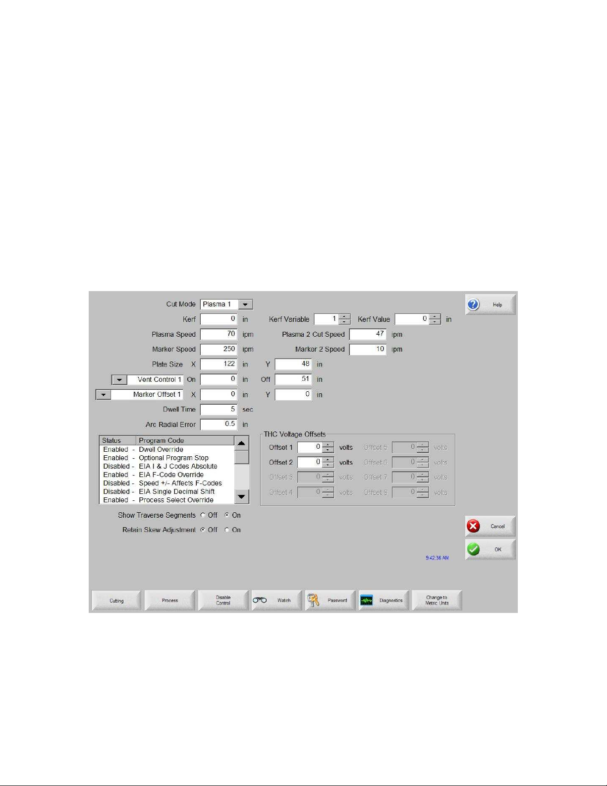
Setups
On the Setup screen, you make the selections that determine how you are going to cut.
Cutting
If you press the Cutting soft key, you can adjust the parameters for the cut mode you
want to use. The available modes are:
• Trial (no cutting)
• Oxy-Fuel
• Plasma
• Laser
• Water jet
Cut Mode
Specifies the current cut mode. Trial mode allows the operator to dry-run the current part
program without cutting.
37
Page 45

Setups
Kerf
Specifies the amount of kerf that will be applied to the current part program. Care should
be taken when selecting a kerf value as this parameter can cause invalid geometries to be
generated. For example, adding a kerf of 0.5” to an arc with a radius of 0.25”. After
entering a kerf value, the kerf compensated cut path can be viewed by pressing the Kerf
soft key under the Part Options menu.
Kerf Variable / Kerf Value
Creates a kerf variable table that assigns a variable to a Kerf value. Up to 200 variables
can be entered to create a reference table.
This kerf variable can be used within a part program to define the kerf value and as torch
parts wear, the kerf value changes. If the kerf variable value is updated as the
consumable wears and changes, the new value will be called by the kerf variable
command with all programs loaded that use the variable.
The EIA-274D part code for left kerf variable is the G43 code.
Example: G43 D1 X0.06
Kerf Variable Setting
Kerf Variable
A number from 1-200 can be used
Kerf Data
The selected kerf value
Trial/Cut Speed
Specifies the speed for the current cut mode. These speeds are saved independently for
trialing and cutting. Both speeds are limited to the maximum machine speed. Cut and
trial speeds can be executed at the embedded F-code speed within a part program.
Marker 1 / Marker 2 Speed
Specifies the speed for the selected marker. These speeds are saved independently for
each marker and are executed through the marker tool selection within a part program.
Marker 1 is activated by EIA RS-274D M09 and M10, or an ESSI 9 and 10. Marker 2 is
activated by EIA RS-274D M013 and M14, or an ESSI 13 and 14.
Plate Size
Specifies the dimensions of the current plate. This dimension is used when loading a part
to determine if it will fit on the plate. It is also used for viewing the part in screen view.
Vent Controls 1 - 50
Enter values for up to fifty programmable zones for fume extraction damper control.
Based on the machine position, the vent control outputs to activate dampers at the
selected zone for increased performance.
38
Page 46

Setups
Marker Offsets 1 - 12
Enter values for up to twelve programmable marker offsets. The machine is offset by this
amount at maximum speed when the appropriate marker code is detected.
Dwell Time
Specifies the amount of dwell (delay) that is inserted into the current part program when
an appropriate RS-274D program block is reached. This time can be overridden in the
part program. For example, in EIA programming a G04 X3 causes a three second dwell
to be inserted at the current program block. A G04 with no X-code inserts a dwell with
the current Dwell Time parameter.
Arc Radial Error
Specifies the arc error tolerance to be used when checking the current segment for
dimensional accuracy. All ESSI or EIA programs are comprised of lines, arcs, and
circles. Arc Radial Error is used to make sure that the starting and ending radial vectors
are within tolerance to describe a valid geometry.
Dwell Override
When this parameter is enabled, embedded dwell G04 X value codes in an RS-274D
program override the operator-entered dwell time.
Optional Program Stop
Allows overriding of the optional program stop code M01 in the current part program. If
enabled, an M01 code operates identically to M00. If disabled, the M01 code is ignored.
EIA I & J Codes
Selects absolute or incremental RS-274D programming mode. In incremental mode, all
offsets for X, Y, I and J are relative to the current block. In absolute mode, all offsets for
X, Y, I and J are relative to an absolute reference point unless they are changed by using
a G92 (set axis presets) program code.
EIA F-Code Override
When this parameter is enabled, embedded F-codes in an RS-274D program override any
operator-entered cut speed.
Speed +/- Affects F-Codes
When this parameter is enabled, the control applies the speed increase/decrease
percentage to all embedded F-codes that are encountered in the part program.
EIA Decimal Shift
Some programming styles are structured so that the decimal point in the EIA positioning
affecting part sizing is assumed. The EIA decimal shift parameter allows the operator to
select the location of the decimal point when translating parts by selecting normal or
single for the correct translation. The selection should be set to Normal unless your part
programs have only a single digit to the right of the decimal point.
39
Page 47

Setups
Process Select Override
When enabled, this feature allows the part program to override the process select input.
Station Select Override
When enabled, this feature allows the part program to override the currently selected
station select input.
Auto Torch Spacing Override
When enabled, this feature allows the part program to override the manually selected
torch spacing inputs.
G97 Loop Count Prompt
When enabled, this feature will post a message on the screen to enter the number of loops
or repeats to be selected when an EIA G97 code without a “T” value is encountered in the
part program.
ESAB Multi Torch Support
When enabled, this feature allows ESAB style ESSI part programs to map codes to
specific station selects.
Mapped
ESSI Code EIA Code Description
7 M37 T1 Select station 1
8 M38 T1 Deselect station 1
13 M37 T2 Select station 2
14 M37 T2 Deselect station 2
15 M37 T3 Select station 3
16 M38 T3 Deselect station 3
Force G40 Kerf Disable
In a part program, kerf is enabled and disabled using EIA G41/ G42 and G40 codes.
Standard operation is to disable kerf at the cut off even if the G40 kerf disable is not in a
program. With this parameter, you can turn off the “forced” G40 kerf disable if no G40
is used in the program by disabling the parameter.
G40 Used in Simple Shapes
This parameter is used with the Force Kerf Disable parameter to allow the G40 code that
is normally inserted in to a simple shape from the shape library to be omitted by disabling
the parameter.
Auto Start after APA
This parameter is used with the Automatic Plate Alignment feature to allow cutting to
begin automatically after completion of the automatic plate alignment.
EIA Code 2 Decimal Shift
Some programming styles are structured so that the decimal point in the EIA positioning
affecting part sizing is assumed. The EIA Code 2 Decimal Shift parameter allows the
operator to select the location of the decimal point when translating parts by selecting
40
Page 48

Setups
normal or single for correct translation. The selection should be set to Normal unless
your part programs require two decimal shift to the right of the decimal point.
M17, M18 Used as Cut Codes
This allows the EIA-274D M17 and M18 codes to be used for cut on and off commands
when enabled.
M76 Rotary Shortest Path
When enabled, this disables tilt and rotate software overtravels for dual tilt-style bevellers
and allows the EIA-274D M76 Rotate go to Home command to select shortest path.
When disabled it allows motion by longest path when homing. This is advantageous for
some bevel head designs.
Stop on Single Arc Lost
If this setting is enabled, any cut sense input that is lost for longer than the arc off time
during the cut pauses the part program or nest with a Cut Sense Lost message.
Show Traverse Segments
Allows traverse segment lines (displayed in yellow) to be turned OFF or ON during all
part preview displays.
Retain Skew Adjustment
Retains the last calculated plate skew for all subsequent parts that are loaded. If disabled,
any new part that is loaded will remove any previously calculated plate skew.
THC Voltage Offset
The THC Voltage Offset parameter is used to offset the individual Sensor THC arc
voltages from the master set arc voltage. This allows the individual THCs to be adjusted
to compensate for consumable wear and obtain optimum cut quality.
41
Page 49

Setups
Reenable All Power Supplies
Press this soft key to re-enable any disabled HD4070 or HPR power supply with auto gas.
This key is enabled only if a power supply has been disabled.
42
Page 50

Setups
Process
Your CNC comes standard with several styles of built-in cut process logic which allows
the cut process timing to be configured for optimum performance. Selection will vary
due to control configuration.
Example:
In the Plasma Cut Type example provided above, various process timing adjustments
may be made to tune the process to the Plasma System and material being cut for the
desired performance. Pressing the Timing Diagram soft key or the space key on a
keyboard allows the user to view a graphical diagram of the process logic
Additionally, each cut type has the ability to save and load the process setups in a file on
the hard drive or to a floppy Diskette or USB memory stick. Pressing the ALT key
allows the Save Data and Load Data functions to be available.
43
Page 51

Setups
Oxy Fuel
The system supports configurations with both the Sensor OHC and other OHC lifters. In
such a mixed configuration, stations must be defined and using stations selects, auto/all
selects or manual selects. Although the system allows both types of OHC lifters, only
one type can be used at a time.
The CNC comes with the following built-in control logic for Oxy Fuel cutting. When
oxy fuel is selected, the following parameters are available to customize the logic for the
metal being cut. As these parameters are changed, the timing diagram below changes to
show the new timing parameters. This screen is located under the Cut Types soft key in
the Setups.
Note: Press the Start key twice to bypass all timers and begin the cut.
44
Page 52
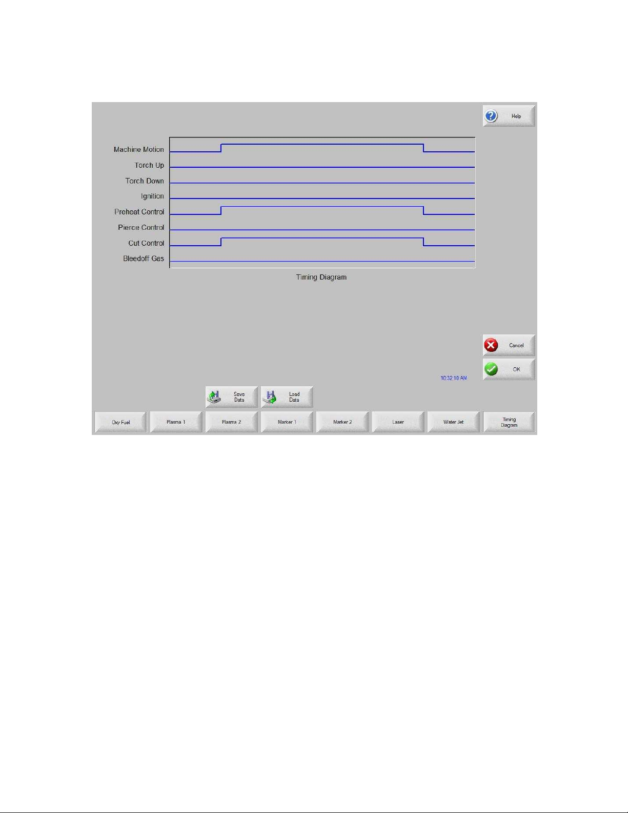
Press the Timing Diagram soft key to view the timing diagram from setups.
Setups
Ignition Time
Specifies the length of time that the oxy fuel igniter is held on at each ignition of the
flame.
Low Preheat
For those cutting systems that are equipped with a Low Preheat feature, this parameter
allows the operator to input a timing delay to activate the Low Preheat output prior to the
High Preheat.
High Preheat
Specifies the length of time to wait at each pierce position for preheating the piece prior
to piercing. During the run-time, the operator may use the SET, EXTEND, or RELEASE
soft keys to customize the preheat length for the particular metal being cut.
Pierce Time
Specifies the amount of delay after the cutting gas is turned on before lowering the torch
to the cut position.
45
Page 53

Setups
Moving Pierce Time
The Moving Pierce Time parameter specifies the amount of time that the Pierce Output
remains on while piercing with motion.
Creep Time
Specifies the amount of time after piercing the part that the torch travels at creep speed.
Creep Speed is determined by a setup parameter at the Speeds setup screen and is a
percentage of the programmed cut speed. After the Creep Time is completed, the control
accelerates to full cut speed. This parameter is helpful in allowing the operator to bring
the cutting surface up to temperature and completely pierce the metal before cutting at
full speed.
Note: Depending on the performance of the plasma system, a creep time may be
required to allow for ramp up of the cut voltage after a pierce.
Primary Torch Up Time
Specifies the amount of time used for torch lift after completing each cut. This is
normally used to provide torch head clearance and return the torch to its predefined rest
position.
Primary Torch Down Time
Specifies the amount of time used to lower the torch at the beginning of each new cut.
This is usually longer than the Pierce Torch Down Time as it involves lowering the torch
from its predefined rest position.
Pierce Torch Up Time
Specifies the amount of time used for torch lift during piercing. This parameter is used to
provide distance between the torch tip and metal surface for cutting.
Pierce Torch Down Time
Specifies the amount of time used for torch lowering during piercing.
Cut Off Time
The Cut Off delay parameter species the amount of time the cut on output will remain on
at the end of a cut.
Bleedoff Time
Specifies the amount of time that the cut torch will pause to purge the oxygen at the end
of a cut segment before traversing to the next cut segment.
Igniters
When “No” is selected, this feature will turn the Preheat on between cut segments. This
is to keep the torch lit for those cutting systems that do not have automatic torch igniters.
For those cutting systems which have automatic torch igniters or that control the torch
gases outside of the control, set this parameter to “Yes”. This tells the control not to turn
on the Preheat between cut segments.
46
Page 54

Preheat During Cut
Specifies whether the Preheat will be left on while cutting.
Staged Pierce
This unique feature works with selected outputs to perform the pierce in a staged
progression of gas pressures.
To enable this setting, select one of the three modes and set the three staged pierce
values:
Setups
47
Page 55

Setups
Controlling Oxy Fuel with Analog Outputs
You can select analog outputs on the I/O screen to control oxygen fuel pressures.
48
Page 56

To select the analog signals that are used for oxygen valve pressure control:
1. On the Machine Setups password screen, press the I/O button.
Setups
2. Select each control and assign an analog output for it.
The controls are listed in groups. All items in each group should be selected and
matched with an analog output:
• Cut Oxygen
• Preheat Oxygen
• Preheat Fuel
• Cut Oxygen TBT 2
• Preheat Oxygen TBT 2
• Preheat Fuel TBT 2
• Cut Oxygen TBT 3
• Preheat Oxygen TBT 3
• Preheat Fuel TBT 3
• Preheat Oxygen TBPT
• Preheat Fuel TBPT
49
Page 57

Setups
3. When you finish selecting controls and assigning outputs, press or click OK.
When you return to the Oxy Fuel screen, the parameters for the control you selected
are added to the screen.
4. Edit the values for the parameters to meet the needs of your process.
Oxy Torch Pressures
Select the type of oxy fuel torch for the process.
Oxy Cut Pressure
Enter the pressure, in pounds per square inch, of the oxy fuel during cutting.
Oxy Ramp Up Time
Enter the time, in seconds, that the oxy fuel takes to reach cutting pressure.
Preheat Low Pressure
Enter the pressure, in pounds per square inch, of the oxy fuel at low pressure during
preheat.
Preheat High Pressure
Enter the pressure, in pounds per square inch, of the oxy fuel at high pressure during
preheat.
Preheat Pressure
Enter the preheat pressure, in pounds per square inch, for the triple bevel head.
Preheat Ramp Up Time
Enter the number of seconds that the process takes to move from low to high pressure
during preheat.
Preheat Ramp Down Time
Enter the number of second that the process takes to move from high to low pressure
during preheat.
Fuel Low Pressure
Enter the pressure, in pounds per square inch, of the oxy fuel at low pressure during
cutting.
Fuel High Pressure
Enter the pressure, in pounds per square inch, of the oxy fuel at high pressure during
cutting.
Fuel Pressure
Enter the fuel pressure, in pounds per square inch, for the triple bevel head.
Fuel Ramp Up Time
50
Page 58

Setups
Enter the number of seconds that the process takes to move from low to high pressure
during cutting.
Fuel Ramp Down Time
Enter the number of second that the process takes to move from high to low pressure
during cutting.
51
Page 59

Setups
Plasma
The control comes with the following built in control logic for Plasma cutting. When
Plasma is selected, the following parameters are available to customize the logic for the
particular metal being cut. As these parameters are changed, the timing diagram below
will change to show the new timing parameters.
52
Page 60
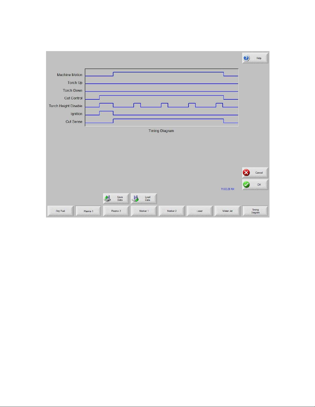
Press the Timing Diagram soft key to view the timing diagram from setups.
Setups
Purge Time
Specifies the time delay from torch ignition until motion is enabled if Arc On Feedback is
off. Purge Time should be set to zero if Arc On Feedback is on.
Pierce Time
Specifies the time delay from when the torch completes lowering until motion is initiated
at Creep Speed. Used to allow the plasma torch to completely pierce the material before
moving.
Creep Time
Specifies the amount of time after piercing the part that the torch travels at Creep Speed.
Creep Speed is determined by a setup parameter at the Speeds setup screen and is a
percentage of the programmed cut speed. After the Creep Time is completed, the control
accelerates to full cut speed.
Cut Off Time
The Cut Off delay parameter species the amount of time the cut on output will remain on
at the end of a cut. A negative Cut Off time up to one second may be used to terminate
the cut output prior to the end of the cut segment. This is used to compensate for response
53
Page 61

Setups
delays of the cut gases that will maintain the cut arc and widen the cut path at the end of
the cut segment.
Full Torch Up Time
Specifies the length of time to raise the torch at the beginning and end of each cut to
provide clearance over the cut pieces. If you are using an automatic height control
system, set Torch Up Time to zero.
Partial Torch Up Time
Specifies the length of time for a partial raise of the torch at the beginning and end of
each cut to provide clearance over the cut pieces. If you are using an automatic height
control system, set Torch Up Time to zero. Note: The Partial Raise parameter must be
enabled.
Torch Down Time
Specifies the length of time to lower the torch at the beginning of each cutting cycle. If
you are using an automatic height control system, set Torch Down Time to zero.
Arc Off Time
Specifies the amount of delay to allow prior to indicating a lost cut signal. This can be
useful in helping to minimize nuisance trips when traveling over previously cut paths in
complex nested parts.
Stop Time
Specifies the amount of time that X/Y motion will pause at the end of a cut. This pause is
advantageous for allowing the torch to completely raise and clear any cut irregularities
before continuing to the next cut segment.
Retract Delay
Retract Delay specifies the amount of time X/Y and lifter motion will pause at the end of
a cut. This allows the cut process to finish before lifting the torch and moving to the next
pierce.
Set Arc Current
The Set Arc Current feature allows the user to set the arc current at the plasma supply.
This feature uses the “Set Current BCD” output from the control to activate the BCD
inputs at the plasma supply. The Set Arc Current parameter is also available for the
HD4070 via the serial link. EIA RS-274D part program code G59 Vvalue Fvalue for
setting current is supported.
Corner Current Percent
The Corner Current Percent feature allows the operator to select a reduced current setting
to be executed when cutting corners to improve cut quality. This value is a percentage of
the Set Current (above) and is active when the Torch Height Disable Output is on. The
Corner Current parameter is also available for the HD4070 via the serial link.
54
Page 62

Setups
Retry On Transfer Fail
The Retry On Transfer Fail feature is used to specify the number of times the control will
attempt to fire the torch in the event that the torch fails to ignite.
Transfer Time
The Transfer Time parameter specifies the amount of time used to attempt ignition of the
torch. The ignition is confirmed by the Arc Sense Input (Arc on Feedback) to the control.
Arc on Feedback
Specifies whether an arc-on (also called Plasma Go, Current Sense, Arc Transferred)
signal from the plasma system to the control is used. With Arc On Feedback on, the
control waits for Cut Sense input to activate before initiating machine motion.
Ignition
Enables use of the Ignition output for use in igniting the plasma torch. If your plasma
system requires a separate ignition signal, toggle Ignition to ON. If not, leave Ignition
OFF.
Dual Grid/THC
The Dual Grid parameter enables use of the Torch Height Disable output. This output is
used to disable an automatic torch height sensor or reduce the plasma current in a
switchable current plasma system when machine speed is less than Plasma Hi/Lo Speed.
Dual Grid/THC Start
If Dual Grid is ON, the start mode can be configured to start (HI) or (LOW) at ignition
time. For switchable plasma systems, this usually means that in low mode the plasma
system will only deliver 50% of the maximum output power.
Partial Raise
Enabling the Partial Raise feature will execute a tool raise at the end of the cut segment
within a nest for the time specified in the Partial Up Time parameter. Full raise will be
executed at the end of the final cut segment.
Torch Down During Cut
Turning on the Torch Down During Cut feature forces the torch down output to remain
on throughout the cut process. This is advantageous for pneumatic style torch lifters that
require a constant output.
Torch Down Between Cuts
Turning on the Torch Down Between Cuts feature forces the Torch Down Output to
remain on while traversing between cut segments.
55
Page 63

Setups
HD3070 Auto Gas Interface
This section provides information on the Hypertherm HD3070® Auto Gas Interface. The
Auto Gas screen is available from the Cut Types screen.
Note: The Auto Gas feature must first be enabled at the Special Password screen and is
designed for use with the six valve autogas console only
The top of the Auto Gas screen lists the valve parameter settings for the HD3070. Valve
settings for the 3070 Auto Gas console are documented in the HD3070 manual. When
the values are set, these become the current setting and the operator can choose to save
the file to the diskette, USB memory stick or hard drive.
The settings at the supply are updated at control power up, whenever the settings are
changed at this screen or through commands in a part program Supply settings are also
updated if power is lost and re-enabled at the power supply. There may be a brief delay
as these power supply settings are communicated from the control to the power supply.
Save Data
Pressing the Save Data soft key will allow the operator to save the current Auto Gas
setting to diskette, USB memory stick or hard drive for future use.
56
Page 64

Setups
Load Data
Pressing the Load Data soft key will allow the operator to Load stored Auto Gas settings
from diskette, USB memory stick or hard drive for use.
If you save the data, a file is created with G59 codes with the selected valve settings.
Here is an example of the data file where all percentages are set to zero.
G59 V65 B0
G59 V66 B0
G59 V67 B0
G59 V68 B0
G59 V69 B0
G59 V70 B0
G59 V71 B0
Test Cutting Gases
Pressing the Test Cutting Gases soft key allows the operator to test the HD3070 Cut
Gases.
Test Preflow Gases
Pressing the Test Preflow Gases soft key allows the operator to test the HD3070 Preflow
Gases.
57
Page 65

Setups
HD3070 Auto Gas I/O
The Interface to the HD3070 Auto Gas console is made through of Single Ended and
BCD (Binary Coded Decimal) inputs. The BCD style of interface allows for exact
settings by use of multiple inputs being active at any time. The active BCD inputs values
are summed together to obtain the exact set point.
These I/O points are wired in the same fashion as our other Single Ended I/O points. The
following I/O points are supplied for use of the HD3070 Auto Gas Console
Inputs
Gas Control Read Complete
Gas Control Error
Outputs
Gas Control Write
Remote Test Operate
Remote Test Preflow
Remote Air Plasma
Remote H35/ N2 Plasma
Remote O2 Plasma
Gas Flow Set 1-100 (BCD)
Valve Select 1-8 (BCD)
58
Page 66

Setups
HD4070 and HPR Overview
The Mariner ™ and Voyager™ III controls offer the additional option of connecting
directly to the Hypertherm HD4070 HyDefinition®, HPR130™ and HPR260™ plasma
supplies for setup. This feature has the ability to improve power supply setup and
operational accuracy while having the flexibility to fine tune the process specific to the
operator’s needs.
When using this advanced feature, all necessary power supply settings are transmitted
from the control directly to the Plasma Supply configuring it for use via serial
communications. The Plasma Supply setup is performed through the use of a Cut Chart
(cut process parameter database) which is based on eight process variables. The
combination of these eight process variables are tied to the settings for the cut process
parameters (e.g. arc voltage, pierce delay, etc.) that are transmitted to the supply. For
additional convenience, consumable part numbers for the Plasma supply are displayed at
the Change Consumable screen.
This database allows the user to select factory recommended settings or amend the
database for personalized settings. The Cut Chart information may be saved or loaded
via the hard drive or floppy drive. The Cut Chart files containing the factory
recommended settings are available from Hypertherm.
Access to the Cut Chart data is available from the Plasma Cut Types or Marker Cut
Types screen using the shift key, as indicated below. The Plasma Supply parameters
must first be enabled in the password protected Station Configuration setups to allow the
Cut Chart Information for the Plasma Supply to be available for use.
Note: Screen information will vary depending on THC selection.
59
Page 67

Setups
Cut Chart
The Cut Chart Database (cut process parameters) transmitted to the power supply is
based on the following eight process variables.
Material Type
The Material Type, such as Mild Steel, Stainless Steel or Aluminum, may be selected.
Current Settings
The appropriate current setting for the material thickness and material type may be
selected.
Plasma / Shield Gases
The appropriate Plasma / Shield gases for the desired process may be selected.
Material Thickness
The desired material thickness may be selected.
60
Page 68

Setups
The following are the Cut Process parameters within the database which are used to
configure the process. Appropriate parameter information is transmitted to the power
supply.
Cut Speed
Specifies the speed for the selected process variables.
Kerf
Specifies the amount of kerf that is applied to the current part program.
Set Arc Voltage
The operator may input the desired Arc Voltage for the material being cut.
Cut Height
The Cut Height setup parameter is used to select the desired cut distance from the plate.
Pierce Height
The Pierce Height setup parameter is used to select the desired Pierce Height. This may
be entered as a multiplication factor that is calculated times the Cut Height or an actual
Pierce Height distance.
Preflow Setting
The appropriate Plasma / Shield Preflow percentages for the desired process may be
selected.
Cutflow Settings
The appropriate Plasma / Shield Cutflow percentages for the desired process may be
selected.
Preflow Time
Specifies the amount of time the Preflow gases are on.
Purge Time
Specifies the time delay from torch ignition until motion is enabled.
Pierce Time
Specifies the time delay from when torch completes lowering until motion is initiated at
Creep Speed. This parameter allows the plasma torch to completely pierce the material
before moving.
Creep Time
Specifies the amount of time after piercing the part that the torch travels at Creep Speed.
Creep Speed is determined by a setup parameter at the Speeds setup screen and is a
percentage of the programmed cut speed. After the Creep Time is completed, the control
accelerates to full cut speed.
61
Page 69

Setups
Save Process
Pressing the Save Process soft key allows the user to save the current process settings to
the hard drive and create a custom user database based on the eight process variables
selected.
Reset Process
Pressing the Reset Process soft key allows the user to reset the current settings to factory
recommend factory defaults based on the eight process variables selected.
Save Cut Charts
Pressing the Save Cut Charts soft key allows the user to save the current User and
Factory databases to Diskette or USB memory stick. User files are designated with a .usr
file extension and the factory files are designated with a .fac file extension
Examples of user and factory file names:
Mild Steel-HT4400-HD4070.usr
Mild Steel-HT4400-HD4070.fac
Load Cut Charts
Pressing the load Cut Charts soft key allows the user to load the factory default database
files which are supplied by Hypertherm in a Text file (.txt), user files (.usr) or factory
files (.fac) from Diskette or USB memory stick.
Factory text file names:
Mild Steel Cut Chart Data mschart.txt
Aluminum Cut Chart Data alchart.txt
Stainless Steel Cut Chart Data sschart.txt
It is recommended that the Database be updated through the control rather than the Power
Supply if the serial communications link is enabled.
Test Preflow
Pressing the Test Preflow soft key performs the Test Preflow Gases feature at the Plasma
supply.
Test Cutflow
Pressing the Test Cutflow soft key performs the Test Cutflow Gases feature at the Plasma
supply.
Notes:
• Refer to the power supply operator’s manual for complete information on the
operation and setup of the plasma supply.
• A serial communication port for the plasma supply must first be selected at the port
configuration screen to be enable the feature for use.
62
Page 70

Setups
• The Plasma supply parameters must first be enabled in the password protected Station
Configuration screen to allow the cut chart information for the plasma supply to be
available for use.
• Power Supplies equipped with the integrated Command® THC can be used with the
control setups. The Command THC must first be enabled for use in the password
protected Station Configuration Screen.
63
Page 71

Setups
Change Consumable
When the power supply link feature has been enabled, consumable data information may
be viewed at the Change Consumable screen.
64
Page 72

Setups
FineLine Overview
The “Type V” control offers the additional option of interfacing directly to InnerLogic’s
FineLine Power Supply for setup via a user selected RS-422 serial port. This advanced
feature transmits all necessary power supply settings from the control directly to the
FineLine power supply configuring it for use.
The power supply setup is performed through the use of a Cut Chart (cut process
parameter database) which is based on eight process variables. The combination of these
eight process variables are tied to the settings for the cut process parameters (e.g. arc
voltage, pierce delay, etc.) that are transmitted to the supply. For additional convenience,
consumable part numbers for the FineLine are displayed at the Change Consumable
screen.
This database allows the user to select factory recommended settings or amend the
database for personalized settings. The Cut Chart information may be saved or loaded
via the hard drive or floppy drive. Specialized Cut Chart files containing the factory
recommended settings are available from the control vendor.
The Power Supply parameter must first be enabled in the password protected Station
Configuration setups to allow the Cut Chart Information for the feature to be enabled for
use. Once selected at the Station Configurations screen, the port must then be selected
for communications on the Ports setup screen and the selected port must then be
configured as RS-422. For more information on configuration of the port, refer to the
Ports information section of this guide.
65
Page 73

Setups
Station Configuration (example)
Access to the FineLine Cut Chart data is available from the Plasma Cut Types or Marker
Cut Types screen using the shift key, as indicated below.
Note: Screen information will vary depending on THC selection.
66
Page 74

Cut Chart
Setups
The Cut Chart Database (cut process parameters) transmitted to the power supply is
based on the following eight process variables.
Material Type
The Material Type, such as Mild Steel, Stainless Steel or Aluminum, may be selected.
Current Settings
The appropriate current setting for the material thickness and material type may be
selected.
Plasma / Shield Gases
The appropriate Plasma / Shield gases for the desired process may be selected.
Material Thickness
The desired material thickness may be selected.
67
Page 75

Setups
The following are the Cut Process parameters within the database which are used to
configure the power supply. Appropriate parameter information is transmitted to the
power supply.
1. Material Type – Mild Steel, Stainless Steel, Aluminum, or Mild Steel (Cold Rolled).
2. Thickness
3. Set Current
4. Pierce Delay
5. Set Preflow Pressure
6. Set Plasma Gas type
7. Set Plasma Pressure
8. Set Shield Gas Type
9. Set Shield Pressure
10. Set Process (Cut/Mark)
The following items are stored in the Cut Chart Data file and will be automatically
updated on the control.
Cut Speed
Specifies the speed for the selected process variables.
Kerf
Specifies the amount of kerf that will be applied to the current part program.
Preflow Time
Specifies the amount of time the Preflow gases are on.
Purge Time
Specifies the time delay from torch ignition until motion is enabled.
Pierce Time
Specifies the time delay from when torch completes lowering until motion is initiated at
Creep Speed. This parameter allows the plasma torch to completely pierce the material
before moving.
Creep Time
Specifies the amount of time after piercing the part that the torch travels at Creep Speed.
Creep Speed is determined by a setup parameter at the Speeds setup screen and is a
percentage of the programmed cut speed. After the Creep Time is completed, the control
accelerates to full cut speed.
68
Page 76

Setups
Database Features
Save Process
Pressing the Save Process soft key allows the user to save the current process settings to
the hard drive creating a custom user database based on the eight process variables
selected.
Reset Process
Pressing the Reset Process soft key allows the user to reset the current settings to factory
recommend factory defaults based on the eight process variables selected.
Save Cut Charts
Pressing the Save Cut Charts soft key allows the user to save the current User and
Factory databases to Diskette or USB memory stick. User files are designated with a .usr
file extension and the factory files are designated with a .fac file extension
Examples of user and factory file names.
Mild Steel-Fineline200-Fineline200.usr
Mild Steel- Fineline200-Fineline200.fac
Load Cut Charts
Pressing the load Cut Charts soft key allows the user to the factory default database files
which are supplied by Hypertherm as a user files (.usr) or factory files (.fac) from
Diskette or USB memory stick.
It is recommended that the Database be updated through the control rather than the Power
Supply if the serial communications link is enabled.
Test Preflow
Pressing the Test Preflow soft key performs the Test Preflow Gases feature at the
HD4070 power supply.
Test Cutflow
Pressing the Test Cutflow soft key performs the Test Cutflow Gases feature at the
HD4070 power supply.
Notes:
• Please refer to the power supply operators manual for complete information on the
operation and setup of the FineLine Power Supply.
• The FineLine Power Supply parameters must first be enabled in the password
protected Station Configuration Screen to allow the Cut Chart Information for the
FineLine to be available for use.
• Serial communications for the FineLine Power supply are established on the user
select communication port. The port must be configured for RS-422 operation.
69
Page 77

Setups
Change Consumable
When the FineLine feature has been enabled, consumable data information may be
viewed at the Change Consumable screen.
70
Page 78

Setups
Marker
The control comes with the following built in marker control logic for marking. When
marking is selected, the following parameters are available to customize the logic for the
particular metal being marked. As these parameters are changed, the timing diagram
below will change to show the new timing parameters. This screen is located under the
Cut Types soft key in Setups.
Marker Interface
The Marking feature from the control is operated through the use of existing I/O points
for cutting torches on the control I/O connector. These I/O points may be switched from
the cutting torch to the marking tool by use of an external relay(s) activated by the
Marker Output or the Marker Output may be used to activate the marking tool.
Please refer to the Machine Interface section of this guide for exact I/O pinout
information.
71
Page 79

Setups
Press the Timing Diagram soft key to view the timing diagram from setups.
Ignition Time
(Ignition Output) Specifies the length of time that the ignition output is held on at each
ignition point.
Marker On Time
(Time Delay) This parameter allows the operator to insert a time delay, which allows the
marker to prepare for operation prior to the start of Marker motion.
Marker Off Time
(Time Delay) This parameter allows the operator to insert a time delay, which allows the
marker to prepare for operation prior to the end of Marker motion.
Marker Up Time
(Torch Up Output) Specifies the length of time to raise the marker at the beginning and
end of each mark.
Marker Partial Up Time
(Torch Up Output) Specifies the length of time for partial raise of the marker at the
beginning and end of each mark. Note: The Partial Raise parameter must be enabled.
72
Page 80

Setups
Marker Down Time
(Torch Down Output) Specifies the length of time to lower the marker at the beginning
of each marking cycle.
73
Page 81

Setups
Set Arc Current
The Set Arc Current feature allows the user to set the arc current at the Plasma Marking
supply. This feature uses the “Set Current BCD” output from the control to activate the
BCD inputs at the Plasma Marking supply. EIA RS-274D part program code G59 Vvalue
Fvalue for setting current is supported.
Corner Current Percent
The Corner Current Percent feature allows the operator to select a reduced current setting
to be executed when cutting corners to improve marking quality. This value is a
percentage of the Set Current (above) and is active when the Torch Height Disable
Output is on.
Ignition
(Ignition Output Enable) The Ignition Off/On selection allows the operator to use the
Ignition Output when marking if set to On.
Cut Control Used for Marking
This parameter is used to determine if the Cut Control output is to be used for activating
the Marking tool. If set to no, the Marking Output would be used.
Marker Down/Up With Each Marker On/Off
The Marker Down/Up With Each Marker On/Off will command the send the appropriate
Up/Down Output commands at each Mark On/ Off.
Arc On Feedback
Specifies whether an arc-on signal from a plasma marking system to the control is used.
With Arc On Feedback ON, the control waits for Cut/Mark Sense input to activate before
initiating machine motion.
Partial Raise
Enabling the Partial Raise feature will execute a tool raise at the end of the Mark within a
nest for the time specified in the Partial Up Time parameter. Full raise will be executed
at the end of the final Mark segment.
Down On During Mark
Turning on the Down On During Mark feature forces the torch down output to remain on
throughout the marking process. This is advantageous for pneumatic style torch lifters
that require a constant output.
Down On Between Marks
Turn on the Down On Between Marks feature to force the Torch Down Output to remain
on while traversing between marking segments.
Note: Please refer to the Program Codes section of this guide for information on the
Marker Font Generator feature.
74
Page 82

Setups
Laser Overview
The Mariner CNC offers a unique Laser process screen directly integrates to the
Hypertherm FAST Laser™ head. This feature has the ability to improve Laser setup and
operational accuracy while having the flexibility to fine tune the process specific to the
operator’s needs.
FAST Laser uses an innovative patent-pending design to create a dual flow zone allowing
significantly higher oxygen assist gas pressures in the tightly defined cut zone established
by the beam geometry, without the uncontrolled burning in the surrounding zone
normally induced by increased assist gas pressures. This accelerated high-velocity
oxygen flow along the beam path not only increases cut speed by fueling the exothermic
reaction, but also reduces sensitivity to common plate fabricating conditions and
variables, most notably plate chemistry and condition.
With this technology, Hypertherm has introduced a line of laser cutting heads that utilize
the FAST Laser process to deliver up to a 20% increase in cut speed over standard CO2
laser heads on plate steel while also significantly expanding the capacity and quality
range of plate laser cutting systems. These combined benefits produce substantial gains in
productivity and unattended operation potential for dedicated plate lasers (4 to 6 kW) –
whether integrated or retrofitted – while also offering expanded capacity range and cost
performance for shared-duty systems (2 to 3 kW). The Hypertherm LH2100 head offers
two different focal lengths: 7.5 and 10.0 inches; the LH2125 adds a 12.5-inch focal
length option for thicker plate. The Hypertherm LH2125/2100 series is used on laser
systems with 1.5” or 2.0” optics. The Hypertherm LH1575 head offers two different focal
lengths: 5.0 and 7.5 inches for 1.5 inch optics.
Integrated with Hypertherm Automation’s Mariner CNC, on-board FAST Laser process
intelligence coupled to process monitoring optics standard on LH-series cutting heads,
achieves improved overall control of the cutting process with fewer system faults and
reduced operator involvement. Dynamic Pierce Control senses and initiates each cut once
the pierce is complete. These combined capabilities maximize uptime while minimizing
total cycle time.
Note: Refer to Laser Information provided with the FAST Laser head for proper
operation.
75
Page 83

Setups
Laser Cut Types Screen
The Alt soft key at the left edge of the soft keys indicates additional soft keys are
available. This allows for test lifter function to be available.
Test Lifter
Pressing the Test Lifter soft key will command the laser head THC1 lifter to lower to the
plate, sense the plate and retract to the pierce height.
76
Page 84

Press the Timing Diagram soft key to view the timing diagram from setups.
Setups
Purge Time
Specifies the time delay for cutting gas purge before start of the laser cut motion is
enabled.
New Gas Purge Time
Specifies the Gas Purge Time for switching from one cutting gas to another cutting gas.
Shutter Time
The Shutter Time parameter is used to specify the amount of time to open the shutter
prior to the laser beam on.
Power Ramp Time
The Power Ramp Time parameter is used to specify the amount of time to ramp up the
laser power prior to the laser pierce.
Pierce Time
Specifies the time delay from when laser head completes lowering until motion is
initiated at creep speed for cutting.
When Manual Pierce Control is selected, this is the total pierce time allowed.
77
Page 85

Setups
With Automatic Pierce Control is selected, this time is an additional delay after pierce is
complete.
Pulse On Time
When Automatic Pulse Mode is selected for pierce control the user can select Pulse On
and Off Time to adjust duty cycle response of the sensor pulses from the laser cutting
head.
Pulse Off Time
When Automatic Pulse Mode is selected for pierce control the user can select Pulse On
and Off Time to adjust duty cycle response of the sensor pulses from the laser cutting
head.
Creep Time
Specifies the amount of time after piercing the material that the laser head travels at
Creep Speed for cutting. Creep Speed is determined by a setup parameter in the Speed
Setup Screen and is a percentage of the programmed cut speed. After the Creep Time is
completed, the control accelerates to full cut speed.
Beam Off Time
The Beam Off Time parameter specifies the amount of time the beam output will be
turned off prior to he stop of motion. This feature can be used to tab parts for attachment
to the skeleton.
Postflow Time
Specifies the amount of time that the cutting gas remains on after the cut is complete.
Cut Height
The Cut Height setup parameter is used to select the desired cut distance above the plate.
This will set the initial cut height before the laser cut motion is activated. Cut Height is
derived from the CHS signal and the calibration curve and represents cut distance from
nozzle tip to the plate.
Pierce Height
The Pierce Height setup parameter is used to select the desired Pierce Height above the
plate. This can be entered as a multiplication factor that is calculated times the Cut
Height or an actual Pierce Height distance.
Lens Cut Position
Sets the focal lens position in the laser head for cutting.
Lens Pierce Position
Sets the focal lens pierce position in the laser head for cutting.
Pulse Laser Time
Sets the Laser Pulse Time duration for a one shot beam alignment.
78
Page 86

Setups
Pulse Laser Power
Sets the Laser Pulse Power for a one shot beam alignment.
Height Control Manual/Automatic
Allows the user to either select a Manual or Automatic Height control for the laser head.
IHS in Manual
The IHS in Manual setup parameter allows the operator to select whether or not to use the
Initial Height Sense feature when operating the Z axis lifter (THC1) in manual mode.
Retract Full/Partial
Selects the retract distance to be set at Full or Partial. In the Full retract mode, the laser
head will retract to the Z-Axis Home position. In Partial retract mode, the laser head will
retract to the set retract distance.
Partial Retract Distance
This setup parameter is used to select the THC 1 Retract Distance when configured for
partial retract mode.
Start IHS Distance
The Start IHS Distance specifies the distance of travel for the THC 1 to move the laser
head at high speed before switching to low speed and beginning Initial Height Sense.
Caution should be taken when selecting this distance so that the laser head does not crash
into the plate.
Preflow During IHS
Selecting ON will activate Preflow gases during the IHS cycle.
Nozzle Contact IHS
This parameter would be set to ON to select the THC 1 to use Contact Sense to detect the
plate during the IHS cycle.
Nozzle Contact During Cut
Nozzle Contact During Cut allows the CNC to detect contact with the plate and generates
a fault if this condition occurs.
Pierce Control Manual/Automatic
Allows the user to select manual or automatic pierce control. Automatic control uses
sensors in the Laser head to detect when the pierce is complete. Manual mode uses a
preset pierce time and preset laser program. Automatic mode dynamically controls laser
duty cycle.
Pierce Mode Pulse/Blast
When Automatic Pierce is selected the user can select to use a definable pulse output or a
single Blast.
79
Page 87

Setups
Pierce Complete
The Automatic Pierce monitors the voltage of sensors in the laser head and compares
them to the value set by this parameter to detect the completion of the pierce.
Next Pulse
Based on sensors in the laser head, the system can determine when the next Laser Pulse is
delivered during Automatic Pierce control. The voltage is derived from the feedback of
the sensors in the laser cutting head.
Cut Chart
A cut chart database allows the user to select factory recommended settings or amend the
database for personalized settings. The Cut Chart information can be saved or loaded via
the hard drive, floppy drive or USB memory stick. The Cut Chart files contain the
factory recommended settings that are available from Hypertherm.
Notes:
• Refer to the FAST Laser operator’s manual for complete information on the operation
and setup of the FAST Laser head.
• The FAST Laser Laser parameters must first be enabled in the password protected
Station Configuration screen to allow use of the Cut Chart Information
• Specific Material, Process Power, Assist Gases, Material Thickness, Focal Length
and Nozzle data fields allow new values to be added. Double click on the field to
enter an new value or press the Plus key “+” to add or “-“ to delete on the keypad.
80
Page 88

Laser Cut Chart Screen
Setups
The Cut Chart Database (cut process parameters) transmitted to configure the laser head
are based on the following process variables. All values are user definable.
Material Type
The Material Type, such as Mild Steel, Stainless Steel or Aluminum, may be selected.
Specific Material
This is a user defined value to allow the user to create a custom database based on unique
characteristics of the material type. Double click on the field or press the Plus key “+” to
enter an new material name or “-“ to delete on the keypad.
Process Power
The appropriate process power (Wattage) for the material thickness and material type for
the desired process.
Assist Gas
The appropriate Assist Gas for the desired process.
Material Thickness
The material thickness for the selected material type.
81
Page 89

Setups
Focal Length
Specific Focal Length lens that needs to be installed in the laser head for the desired
process.
Nozzle
Diameter and type of nozzle that needs to be installed for the desired process.
Test Gas
Pressing the Test Gas soft key performs the Test Gas feature of the cutting assist gas
delivery system.
The following parameters are the Cut Process parameters within the database, which are
then available to configure the specific process.
Set Power
The Set Power parameter allows the user set the power (watts) to be used during the cut
process. This value can be less than the process power.
Cut Speed
Specifies the Cut Speed for the selected material process.
Kerf
Specifies the amount of kerf that will be applied to the current part program.
Cut Height
The Cut Height setup parameter is used to select the desired cut distance from the nozzle
tip to the plate. Cut Height is derived from the CHS signal and the calibration curve.
Pierce Height
The Pierce Height setup parameter is used to select the desired Pierce Height. This may
be entered as a multiple factor that is calculated value of the Cut Height or an actual
Pierce Height distance.
Lens Cut Position
Sets the focal lens position in the laser head for cutting.
Lens Pierce Position
Sets the focal lens pierce position in the laser head for cutting.
Resonator On Time
During automated power up this allows a specific time for the resonator to power up.
Purge Time
Specifies the time delay from switching from one cutting gas type to another cutting gas
type.
82
Page 90

Setups
Pierce Time
Specifies the time delay from when laser head completes lowering until motion is
initiated at creep speed for cutting.
When Manual Pierce Control is selected, this is the total pierce time allowed.
With Automatic Pierce Control is selected, this time is an additional delay after pierce is
complete.
Pulse On Time
When Automatic Pulse Mode is selected for pierce control the user can select Pulse on
time to adjust the pulse.
Pulse Off Time
When Automatic Pulse Mode is selected for pierce control the user can select Pulse on
and off time to adjust the pulse. The Off Time starts when the sensor signal falls below
the next pulse threshold.
Creep Time
Specifies the period after pierce complete that the laser head travels at Creep Speed.
Creep Speed is determined by a setup parameter in the Speeds setup screen and is a
percentage of the programmed cut speed. After Creep Time is complete, the control
accelerates to full cut speed.
Pierce Complete
The Automatic Pierce monitors voltage of sensors in the laser head to detect completion
of the pierce. This is used in conjunction with Pulse On Time, Pulse Off Time and next
pulse.
Next Pulse
Based on sensors in the laser head, the system can determine when the next pulse occurs.
The Next Pulse will be delivered when the voltage drops below the Next Pulse setting.
Start Corner Power
The Start Corner Power allows the user to define a speed where the corner power analog
signal will be used to start to decrease laser power. This is defined as a percentage of cut
speed.
See Corner Power graph, where the example shows this set to 80%.
Minimum Corner Power
This parameter defines the minimum laser resonator power to switch when the cut speed
reduces to zero in a corner. This is defined as a percentage of selected power (watts). See
Corner Power graph, where the example shows 30%.
83
Page 91

Setups
Example of Corner Power Graph
Save Process
Press the Save Process soft key to save the current process settings to the hard drive and
create a custom user database based on the eight process variables selected.
Rest Process
Pressing the Reset Process soft key allows the user to reset the current settings to factory
recommend factory defaults based on the eight process variables selected.
Save Cut Charts
Pressing the Save Cut Charts soft key allows the user to save the current User and
Factory databases to Diskette or USB memory stick. User files are designated with a .usr
file extension and the factory files are designated with a .fac file extension
Load Cut Charts
Pressing the load Cut Charts soft key allows the user to the factory default database files
which are supplied by Hypertherm in a Text file (.txt), user files (.usr) or factory files
(.fac) from Diskette or USB memory stick.
Pulse Laser Time
Sets the Laser Pulse Time duration for a one shot beam alignment.
Pulse Laser Power
Sets the Laser Pulse Power for a one shot beam alignment.
Height Control Manual/Automatic
Allows the user to select a manual or automatic height control for the laser head.
84
Page 92

Setups
IHS in Manual
The IHS in Manual setup parameter allows the operator to select whether or not to use the
Initial Height Sense feature when operating the Z axis lifter (THC1) in manual mode.
Retract Full/Partial
Selects the retract distance to be set at Full or Partial. In the Full retract mode, the laser
head will retract to the Z-Axis Home position. In Partial retract mode, the laser head will
retract to the set retract distance.
Partial Retract Distance
This setup parameter is used to select the THC Retract Distance when configured for
partial retract mode.
Start IHS Distance
The Start IHS Distance specifies the distance of travel for the THC to move the laser
head at high speed before switching to low speed and beginning Initial Height Sense.
Caution should be taken when selecting this distance so that the laser head does not crash
into the plate.
Preflow During IHS
Select ON to activate Preflow gas during the IHS cycle.
Nozzle Contact IHS
This parameter would be set to ON to select the THC to use Contact Sense to detect the
plate during the IHS cycle.
Nozzle Contact During Cut
Nozzle Contact During Cut allows the CNC to detect contact with the plate and fault.
Pierce Control Manual/Automatic
Allows the user to select manual or automatic pierce control. Automatic control uses
sensors in the Laser head to detect when the pierce is complete.
Pierce Mode Pulse/Blast
When Automatic Pierce is selected the user can select to use a definable pulse output or a
single Blast.
Pierce Complete
The Automatic Pierce monitors voltage of sensors in the laser head to detect completion
of the pierce.
Next Pulse
Based on sensors in the laser head, the system can determine when the next Pulse Pierce
occurs during Automatic Pierce control. The voltage is derived from the feedback of the
sensors.
85
Page 93

Setups
Cut Chart
A cut chart database allows the user to select factory recommended settings or amend the
database for personalized settings. The Cut Chart information can be saved or loaded via
the hard drive, floppy drive or USB memory stick. The Cut Chart files contain the
factory recommended settings that are available from Hypertherm.
Notes:
• Refer to the FAST Laser operator’s manual for complete information on the operation
and setup of the FAST Laser head.
• The FAST Laser Laser parameters must first be enabled in the password protected
Station Configuration screen to allow use of the Cut Chart Information
• Specific Material, Process Power, Assist Gases, Material Thickness, Focal Length
and Nozzle data fields allow new values to be added. Double click on the field to
enter an new value or press the Plus key “+” to add or “-“ to delete on the keypad.
86
Page 94

Water Jet
Setups
Press the Timing Diagram soft key to view the timing diagram from setups.
87
Page 95

Setups
Purge Time
Specifies the time delay from torch ignition until motion is enabled.
Pierce Time
Specifies the time delay from when cutting tool completes lowering until motion is
initiated at Creep Speed. Used to allow the cutting tool to completely pierce the material
before moving.
Creep Time
Specifies the amount of time after piercing the part that the torch travels at Creep Speed.
Creep Speed is determined by a setup parameter at the Speeds setup screen and is a
percentage of the programmed cut speed. After the Creep Time is completed, the control
accelerates to full cut speed.
Abrasive Off Time
The Abrasive Off delay parameter species the amount of time the abrasive will remain on
at the end of a cut.
Abrasive Charging
When selected, the Abrasive Charging feature will charge or fill the abrasive into the
cutting system for use while cutting.
88
Page 96
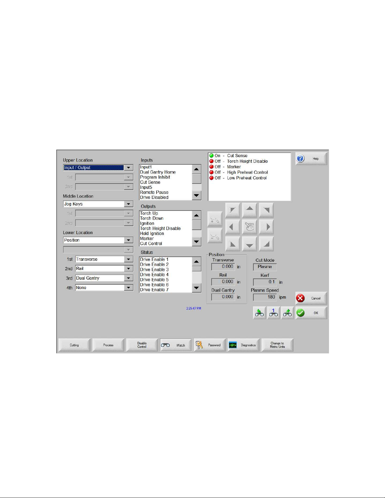
Setups
Watch
The control comes with a unique function for watching critical process related parameters
during cutting. The Watch window allows the operator to customize a certain portion of
the screen to display functions that are critical for your particular cutting operation.
Whether it is Current Speed, Position, I/O status, or torch consumable life, you now have
the flexibility to display the information that you want to see.
As these parameters are turned on or off, the Watch window will be updated with the new
graphical widget. Widget is a GUI programmer’s term for defining icons which
graphically display information.
Several options are available to personalize the Watch window and not all options can be
viewed at one time. The options are grouped into two sizes of widgets or icons. Large
widgets may be placed into the upper position at the top of the Watch window or in the
middle of the Watch window. Small widgets are positioned in the lower left corner of the
Watch Window next to the cut information and clock. The cut information and clock at
the lower right may not be edited.
Selections in the Watch window will change slightly based on the control I/O
configuration and machine option selections that have been enabled.
The Watch positions will allow for the following selections.
89
Page 97

Setups
None
Selecting None leaves the selected position blank.
Input/Output
Allows current state of selected Input, Outputs or Status information to be displayed
during cutting. This can be especially useful in debugging gas control sequencing
problems. To add or delete a desired Input, Output or Status point to the Input/Output list
box, double-click an item or highlight an item and + (add) or – (delete) keys on the alphanumeric keypad.
Position
Allows the position for the selected axis to be displayed. Only two axes may be displayed
at the Upper or Middle locations. The Lower location will allow up to four axes to be
displayed.
Following Error
Allows the Following Error to be displayed. Following Error is the distance between the
position the control has calculated and the actual position of the torch. A large Following
Error may indicate that the cut speed selected may be beyond the capability of the cutting
system. Only two axes may be displayed at the Upper or Middle locations. The Lower
location will allow up to four axes to be displayed.
Command Voltage
Allows the user to view directional motion command voltage being sent to the amplifier
for velocity type drives. This displayed voltage also equates to current being commanded
for motion in current type drives. Peak voltage can be displayed for a specified amount
of time.
Temperature
Selecting to add the Temperature information to the Watch window will display the
current temperature inside the control in Fahrenheit or Celsius (selected at the Special
Setups screen).
Note: Specific control hardware is required.
Speedometer
Allows cut speed, maximum machine speed and current machine speed to be graphically
displayed while cutting.
Oxy Fuel Torch Tip
Allows the selected oxy fuel torch tip (1- 12) consumable life to be graphically displayed
while cutting. This is especially useful in helping to determine when the torch tip should
be replaced and keeping track of torch tip data for statistical process control (SPC).
90
Page 98

Setups
Plasma Torch Tip
Allows the selected plasma torch tip (1- 8) consumable life to be graphically displayed
while cutting. This is especially useful in helping to determine when the torch tip should
be replaced and keeping track of torch tip data for statistical process control (SPC).
Plasma Electrode
Allows the selected plasma electrode (1- 8) consumable life to be graphically displayed
while cutting. This is especially useful in helping to determine when the electrode should
be replaced and keeping track of electrode data for statistical process control (SPC).
Jog Keys
Selecting the jog keys option allows a directional keypad to be added to the watch
window for manual motion directly from the touch screen. The operator can press the
hand ICON in the middle of the navigation pad to enable manual mode. Select the
desired move speed and press the corresponding arrow for manual motion in the desired
direction.
Process Data
The Process Data option allows the user to view up to four selected items for a selected
cut or marking process. Process timers and status items for Oxy Fuel, Plasma, Marker,
Water jet and Laser may be selected. Note: The process data will only be displayed
during the current cut process. Example: Plasma 1 process parameters will only be
displayed in the Watch window at the main cut screen while cutting in Plasma 1 Mode.
Laser Nozzle
Laser Nozzle consumable life to be graphically displayed while cutting. This is
especially useful in helping to determine when the nozzle should be replaced and keeping
track of nozzle data for statistical process control (SPC).
HPR Power Supply
Allows the user to view status for inputs, outputs and gas pressures for the HPR autogas
console. Up to four power supplies may be monitored. This is generally used for
service diagnostics only.
Multiple Watch Windows
Up to ten different Watch windows may be configured on the control for quick selection
and viewing of the Watch icons.
To configure different Watch windows for viewing, first access the Watch setup screen.
Press the number ICON to enter a number or the Left/Right arrows to move up and down
through the selections. The different Watch windows can be selected and viewed during
operation using the same selection process.
91
Page 99

Setups
Example
92
Page 100

Shape Manager
Shape Library
The CNC contains a built-in Shape Library with more than 68 commonly used shapes.
These shapes are parametric. Parametric shapes are shapes whose size or geometry you
can edit. The shapes in the library are color-coded from easiest (green) to hardest
(black).
To select a simple shape:
1. On the Main screen, press Shape Library
2. Double click a shape.
3. Press OK.
4. If the selection is incorrect, press Cancel and select the shape again.
Keypad operation:
1. Use the arrow keys to navigate to a shape.
2. Press Enter.
The shape is displayed with the default parameters or the parameters from the last time
this shape was edited. For more information on the available shapes, see Files.
93
 Loading...