

Page 1

®
MicroEDGE
Pro
HyPath
Picopath
SERCOS II
SERCOS III
Shape cutting control
Instruction manual
807290 – Revision 2
Page 2

Page 3

MicroEDGE Pro
®
Shape cutting control
Instruction Manual
(P/N 807290)
Revision 2 – December, 2013
Hypertherm, Inc.
Hanover, NH USA
www.hypertherm.com
© Copyright 2013 Hypertherm, Inc.
All Rights Reserved
ArcGlide, EDGE, HPR, Hypertherm, MicroEDGE, Phoenix, and Sensor are trademarks of Hypertherm, Inc.
and may be registered in the United States and/or other countries
Page 4

Hypertherm Inc.
Etna Road, P.O. Box 5010
Hanover, NH 03755 USA
603-643-3441 Tel (Main Office)
603-643-5352 Fax (All Departments)
info@hypertherm.com (Main Office Email)
800-643-9878 Tel (Technical Service)
technical.service@hypertherm.com (Technical Service Email)
800-737-2978 Tel (Customer Service)
customer.service@hypertherm.com (Customer Service Email)
866-643-7711 Tel (Return Materials Authorization)
877-371-2876 Fax (Return Materials Authorization)
return.materials@hypertherm.com (RMA email)
Hypertherm Plasmatechnik GmbH
Technologiepark Hanau
Rodenbacher Chaussee 6
D-63457 Hanau-Wolfgang, Deutschland
49 6181 58 2100 Tel
49 6181 58 2134 Fax
49 6181 58 2123 (Technical Service)
Hypertherm (S) Pte Ltd.
82 Genting Lane
Media Centre
Annexe Block #A01-01
Singapore 349567, Republic of Singapore
65 6841 2489 Tel
65 6841 2490 Fax
65 6841 2489 (Technical Service)
Hypertherm (Shanghai) Trading Co., Ltd.
Unit 301, South Building
495 ShangZhong Road
Shanghai, 200231
PR China
86-21-60740003 Tel
86-21-60740393 Fax
Hypertherm Europe B.V.
Vaartveld 9
4704 SE
Roosendaal, Nederland
31 165 596907 Tel
31 165 596901 Fax
31 165 596908 Tel (Marketing)
31 165 596900 Tel (Technical Service)
00 800 4973 7843 Tel (Technical Service)
Hypertherm Japan Ltd.
Level 9, Edobori Center Building
2-1-1 Edobori, Nishi-ku
Osaka 550-0002 Japan
81 6 6225 1183 Tel
81 6 6225 1184 Fax
Hypertherm Brasil Ltda.
Rua Bras Cubas, 231 – Jardim Maia
Guarulhos, SP - Brasil
CEP 07115-030
55 11 2409 2636 Tel
55 11 2408 0462 Fax
Hypertherm México, S.A. de C.V.
Avenida Toluca No. 444, Anexo 1,
Colonia Olivar de los Padres
Delegación Álvaro Obregón
México, D.F. C.P. 01780
52 55 5681 8109 Tel
52 55 5683 2127 Fax
Hypertherm Korea Branch
#3904 Centum Leaders Mark B/D,
1514 Woo-dong, Haeundae-gu, Busan
Korea, 612-889
82 51 747 0358 Tel
82 51 701 0358 Fax
12/2/13
Page 5

CONTENTS
Contents ........................................................................................................................................................................................ i
Safety ........................................................................................................................................................................................ S-1
Recognize safety information ................................................................................................................................................................. S-2
Follow safety instructions ........................................................................................................................................................................ S-2
Electrical hazards ...................................................................................................................................................................................... S-2
Electric shock can kill ............................................................................................................................................................................... S-3
Cutting can cause fire or explosion ...................................................................................................................................................... S-4
Toxic fumes can cause injury or death ................................................................................................................................................. S-5
Static electricity can damage circuit boards ...................................................................................................................................... S-6
Compressed gas equipment safety ...................................................................................................................................................... S-6
Grounding safety....................................................................................................................................................................................... S-6
Gas cylinders can explode if damaged ................................................................................................................................................ S-6
A plasma arc can cause injury and burns ............................................................................................................................................ S-7
Arc rays can burn eyes and skin ............................................................................................................................................................ S-7
Noise can damage hearing ..................................................................................................................................................................... S-8
Pacemaker and hearingaid operation ................................................................................................................................................. S-8
A plasma arc can damage frozen pipes .............................................................................................................................................. S-8
Dry dust collection information .............................................................................................................................................................. S-9
Laser radiation .........................................................................................................................................................................................S-10
Additional safety information ................................................................................................................................................................S-11
Warning labels .........................................................................................................................................................................................S-11
Symbols and Marks ................................................................................................................................................................................S-13
Product Stewardship ......................................................................................................................................................... PS-1
Environmental Stewardship ............................................................................................................................................. ES-1
Electromagnetic Compatibility (EMC) ......................................................................................................................EMC-1
Warranty .................................................................................................................................................................................. W-1
Specifications ..........................................................................................................................................................................1-1
MicroEDGE Pro Instruction Manual 807290 i
Page 6

Table of ConTenTs
Main features of an automated cutting system ...................................................................................................................................1-2
CNC ...................................................................................................................................................................................................1-3
Cutting table .....................................................................................................................................................................................1-3
Plasma arc cutting (PAC) system ................................................................................................................................................1-3
Control box .......................................................................................................................................................................................1-4
Drive system .....................................................................................................................................................................................1-4
Torch height control (THC) ...........................................................................................................................................................1-4
Oxyfuel torch ....................................................................................................................................................................................1-4
Marker ................................................................................................................................................................................................1-4
Overview of MicroEDGE Pro ..................................................................................................................................................................1-5
Common features ............................................................................................................................................................................1-5
System options ................................................................................................................................................................................1-5
Rear panel .........................................................................................................................................................................................1-6
System specifications ...............................................................................................................................................................................1-7
Machine interface configurations ...........................................................................................................................................................1-8
HyPath configuration ......................................................................................................................................................................1-8
Picopath configuration ...................................................................................................................................................................1-9
SERCOS II configuration ...........................................................................................................................................................1-10
SERCOS III configuration ..........................................................................................................................................................1-11
Integrated Sensor THC ...............................................................................................................................................................1-12
Secondary enclosure requirements .................................................................................................................................................... 1-13
Interior temperature ......................................................................................................................................................................1-13
Air circulation ................................................................................................................................................................................. 1-13
AC input..........................................................................................................................................................................................1-13
Installation ................................................................................................................................................................................2-1
Upon receipt ...............................................................................................................................................................................................2-3
Claims ...........................................................................................................................................................................................................2-3
Installation requirements...........................................................................................................................................................................2-3
Placement of system components .........................................................................................................................................................2-3
Mounting the CNC ....................................................................................................................................................................................2-4
Mounting hole patterns on the bottom of the CNC ................................................................................................................2-4
X and Y axis configuration .......................................................................................................................................................................2-5
AC power .....................................................................................................................................................................................................2-6
Power cable ......................................................................................................................................................................................2-6
Chassis grounding .....................................................................................................................................................................................2-7
Interface ports .............................................................................................................................................................................................2-8
Hypernet interface ...........................................................................................................................................................................2-8
LAN interface ....................................................................................................................................................................................2-8
USB interface (5) ............................................................................................................................................................................2-8
ii MicroEDGE Pro Instruction Manual 807290
Page 7

Table of ConTenTs
Serial ports (4) .................................................................................................................................................................................2-8
VGA Port 1 .......................................................................................................................................................................................2-8
Picopath connections ...............................................................................................................................................................................2-9
Picopath I/O connections ..............................................................................................................................................................2-9
Picopath I/O connector ..............................................................................................................................................................2-10
Picopath I/O circuit examples .................................................................................................................................................. 2-11
Picopath drive/encoder connectors ......................................................................................................................................... 2-12
Picopath pin-outs for servo drive connectors .................................................................................................................2-13
Encoder voltage options on the Picopath interface ........................................................................................................................ 2-14
Encoder jumper options ..............................................................................................................................................................2-14
HyPath connections ............................................................................................................................................................................... 2-17
HyPath I/O .....................................................................................................................................................................................2-17
HyPath inputs ................................................................................................................................................................................ 2-18
HyPath input circuit examples .............................................................................................................................................. 2-18
HyPath outputs .............................................................................................................................................................................2-20
HyPath output circuit examples ........................................................................................................................................... 2-20
HyPath I/O connectors ...............................................................................................................................................................2-23
HyPath I/O pin-outs ................................................................................................................................................................2-24
HyPath 4-axis servo connectors ............................................................................................................................................... 2-25
HyPath servo connector ........................................................................................................................................................ 2-25
Analog connections ................................................................................................................................................................................2-27
Sensor THC connector ............................................................................................................................................................... 2-27
Pin-outs for Integrated Sensor THC 1 and 2 connectors ............................................................................................. 2-27
THC cable specifications ........................................................................................................................................................... 2-28
Pin-outs for voltage divider board 3 (VDC3) connectors .............................................................................................. 2-28
Pin-out for the cable between J2 on VDC3 and THC 1 on the CNC ........................................................................ 2-28
Joystick and speedpot connector ............................................................................................................................................. 2-29
Pin-outs for joystick and speedpot connector .................................................................................................................2-29
Joystick and speedpot cable adapter for MicroEDGE CNC (223252) .......................................................................... 2-30
SERCOS II I/O configuration ...............................................................................................................................................................2-31
SERCOS III I/O configuration ..............................................................................................................................................................2-32
SERCOS III Cable ....................................................................................................................................................................... 2-32
Serial port configuration ........................................................................................................................................................................ 2-33
Serial ports 1 and 2 ..................................................................................................................................................................... 2-33
Serial ports 3 and 4 ..................................................................................................................................................................... 2-33
Remote on/off cable ............................................................................................................................................................................... 2-35
Wireless network card ........................................................................................................................................................................... 2-36
Preparing to install the antenna .................................................................................................................................................2-36
Installing the antenna ................................................................................................................................................................... 2-36
Checking the wireless network in Windows .......................................................................................................................... 2-37
Mapping a network drive ............................................................................................................................................................2-38
MicroEDGE Pro Instruction Manual 807290 iii
Page 8

Table of ConTenTs
Adding a folder in Phoenix .........................................................................................................................................................2-39
Operation ..................................................................................................................................................................................3-1
Operating the CNC ...................................................................................................................................................................................3-2
Operator console ............................................................................................................................................................................3-2
Touch screen LCD ..........................................................................................................................................................................3-2
LCD display ......................................................................................................................................................................................3-2
Screen navigation ............................................................................................................................................................................3-3
Help ....................................................................................................................................................................................................3-4
View additional manuals ................................................................................................................................................................3-4
Show bookmarks .............................................................................................................................................................................3-5
Automated operations...............................................................................................................................................................................3-5
Align Wizard .....................................................................................................................................................................................3-5
CutPro Wizard .................................................................................................................................................................................3-6
Using Phoenix without a touch screen ..................................................................................................................................................3-6
PC keyboard .....................................................................................................................................................................................3-6
Updating Phoenix software ......................................................................................................................................................................3-7
Updating the software ....................................................................................................................................................................3-7
Updating the Help ...........................................................................................................................................................................3-7
Updating the cut charts .................................................................................................................................................................3-8
Maintenance and Diagnostics ............................................................................................................................................4-1
Introduction .................................................................................................................................................................................................4-3
Diagnostic tests..........................................................................................................................................................................................4-4
Serial test ..........................................................................................................................................................................................4-6
USB test ............................................................................................................................................................................................4-7
I/O test ...............................................................................................................................................................................................4-8
Axis test ..........................................................................................................................................................................................4-10
THC test ......................................................................................................................................................................................... 4-11
LAN and Hypernet tests .............................................................................................................................................................4-12
Joystick and speedpot test .........................................................................................................................................................4-13
Troubleshooting.......................................................................................................................................................................................4-14
Introduction .................................................................................................................................................................................... 4-14
MicroEDGE Pro troubleshooting tables ..................................................................................................................................4-15
Power up ................................................................................................................................................................................... 4-15
Display ....................................................................................................................................................................................... 4-15
Field power failure ................................................................................................................................................................... 4-15
Input failure ............................................................................................................................................................................... 4-16
Output failure ...........................................................................................................................................................................4-16
Hypernet .................................................................................................................................................................................... 4-17
LAN connection ....................................................................................................................................................................... 4-17
iv MicroEDGE Pro Instruction Manual 807290
Page 9

Table of ConTenTs
Motion issues ........................................................................................................................................................................... 4-18
THC ............................................................................................................................................................................................ 4-20
Serial communication issues ................................................................................................................................................ 4-21
USB issues ............................................................................................................................................................................... 4-21
Cut quality ................................................................................................................................................................................. 4-21
CNC temperature ...................................................................................................................................................................4-22
CNC is slow ............................................................................................................................................................................. 4-22
Wireless troubleshooting ...................................................................................................................................................................... 4-23
Component locations and information ............................................................................................................................................... 4-24
HyPath 24 I/O board (141070) ................................................................................................................................................ 4-25
Motherboard (141110) ............................................................................................................................................................... 4-27
SERCOS II master board (141116) ........................................................................................................................................4-28
SERCOS III master board (141310) .......................................................................................................................................4-29
Picopath 4-axis servo board (141122) ................................................................................................................................... 4-30
Analog board (141125) .............................................................................................................................................................. 4-34
Power distribution board (141153) ......................................................................................................................................... 4-36
SERCOS II and SERCOS III serial isolation and utility board (141194/141307) ....................................................... 4-38
HyPath 4-axis servo board (141197) ...................................................................................................................................... 4-40
CPC analog breakout board (141210) ..................................................................................................................................4-42
HyPath and Picopath 4-axis MCC, utility, and serial isolation board (141222) ............................................................ 4-44
Picopath 2-axis servo board (141254) ................................................................................................................................... 4-47
Picopath 2-axis MCC, utility, and serial isolation board (141256) ...................................................................................4-50
Parts List ...................................................................................................................................................................................5-1
Common MicroEDGE Pro parts .............................................................................................................................................................5-2
Picopath MicroEDGE Pro parts .............................................................................................................................................................5-4
HyPath MicroEDGE Pro parts ................................................................................................................................................................5-5
SERCOS II and SERCOS III MicroEDGE Pro parts .........................................................................................................................5-6
Common test plugs ...................................................................................................................................................................................5-7
Picopath test plugs ....................................................................................................................................................................................5-8
HyPath test plugs.......................................................................................................................................................................................5-9
Cable connector kits .............................................................................................................................................................................. 5-10
Wiring Diagrams .....................................................................................................................................................................6-1
Introduction .................................................................................................................................................................................................6-1
Wiring diagram symbols ...........................................................................................................................................................................6-1
MicroEDGE Pro Instruction Manual 807290 v
Page 10

Table of ConTenTs
vi MicroEDGE Pro Instruction Manual 807290
Page 11

Safety
In this section:
Recognize safety information ................................................................................................................................................................. S-2
Follow safety instructions ........................................................................................................................................................................ S-2
Electrical hazards ...................................................................................................................................................................................... S-2
Electric shock can kill ...............................................................................................................................................................................S-3
Cutting can cause fire or explosion ...................................................................................................................................................... S-4
Toxic fumes can cause injury or death ................................................................................................................................................. S-5
Static electricity can damage circuit boards ...................................................................................................................................... S-6
Compressed gas equipment safety ...................................................................................................................................................... S-6
Grounding safety ...................................................................................................................................................................................... S-6
Gas cylinders can explode if damaged ................................................................................................................................................ S-6
A plasma arc can cause injury and burns ............................................................................................................................................ S-7
Arc rays can burn eyes and skin ............................................................................................................................................................ S-7
Noise can damage hearing ..................................................................................................................................................................... S-8
Pacemaker and hearingaid operation ................................................................................................................................................. S-8
A plasma arc can damage frozen pipes .............................................................................................................................................. S-8
Dry dust collection information .............................................................................................................................................................. S-9
Laser radiation ......................................................................................................................................................................................... S-10
Additional safety information ................................................................................................................................................................S-11
Warning labels .........................................................................................................................................................................................S-11
Symbols and Marks ................................................................................................................................................................................S-13
Hypertherm S-1
03/10
Page 12

Safety
RECOGNIZE SAFETY INFORMATION
The symbols shown in this section are used to identify
potential hazards. When you see a safety symbol in this
manual or on your machine, understand the potential
for personal injury, and follow the related instructions
toavoid the hazard.
FOLLOW SAFETY INSTRUCTIONS
Read carefully all safety messages in this manual and
safety labels on your machine.
• Keep the safety labels on your machine in good
condition. Replace missing or damaged labels
immediately.
• Learn how to operate the machine and how to use
thecontrols properly. Do not let anyone operate it
without instruction.
• Keep your machine in proper working condition.
Unauthorized modifications to the machine may affect
safety and machine service life.
DANGER WARNING CAUTION
Hypertherm uses American National Standards Institute
guidelines for safety signal words and symbols. A signal
word DANGER or WARNING is used with a safety
symbol. DANGER identifies the most serious hazards.
• DANGER and WARNING safety labels are located
onyour machine near specific hazards.
• DANGER safety messages precede related
instructions in the manual that will result in serious
injury or death if not followed correctly.
• WARNING safety messages precede related
instructions in this manual that may result in injury
ordeath if not followed correctly.
• CAUTION safety messages precede related
instructions in this manual that may result in
minor injury or damage to equipment if not
followedcorrectly.
ELECTRICAL HAZARDS
• Only trained and authorized personnel may open this
equipment.
• If the equipment is permanently connected, turn it off,
and lock out/tag out power before the enclosure is
opened.
• If power is supplied to the equipment with a cord,
unplug the unit before the enclosure is opened.
• Lockable disconnects or lockable plug covers must
be provided by others.
• Wait 5 minutes after removal of power before
entering the enclosure to allow stored energy to
discharge.
• If the equipment must have power when the
enclosure is open for servicing, arc flash explosion
hazards may exist. Follow ALL local requirements
(NFPA 70E in the USA) for safe work practices and
for Personal Protective Equipment when servicing
energized equipment.
• The enclosure shall be closed and the proper earth
ground continuity to the enclosure verified prior to
operating the equipment after moving, opening, or
servicing.
• Always follow these instructions for disconnecting
power before inspecting or changing torch
consumable parts.
S-2 Hypertherm
03/10
Page 13

ELECTRIC SHOCK CAN KILL
Safety
Touching live electrical parts can cause a fatal shock or
severe burn.
• Operating the plasma system completes an electrical
circuit between the torch and the workpiece. The
workpiece and anything touching the workpiece are
part of the electrical circuit.
• Never touch the torch body, workpiece or the waterin
awater table when the plasma system isoperating.
Electric shock prevention
All Hypertherm plasma systems use high voltage
in the cutting process (200 to 400 VDC are
common). Take the following precautions when
operating this system:
• Wear insulated gloves and boots, and keep your body
and clothing dry.
• Do not stand, sit or lie on – or touch – any wet
surface when using the plasma system.
• Insulate yourself from work and ground using dry
insulating mats or covers big enough to prevent any
physical contact with the work or ground. If you must
work in or near a damp area, use extreme caution.
• Provide a disconnect switch close to the power
supply with properly sized fuses. This switch allows
the operator to turn off the power supply quickly in
anemergency situation.
• When using a water table, be sure that it is correctly
connected to earth ground.
• Install and ground this equipment according to the
instruction manual and in accordance with national
and local codes.
• Inspect the input power cord frequently for damage
or cracking of the cover. Replace a damaged power
cord immediately. Bare wiring can kill.
• Inspect and replace any worn or damaged torch
leads.
• Do not pick up the workpiece, including the waste
cutoff, while you cut. Leave the workpiece in place
or on the workbench with the work cable attached
during the cutting process.
• Before checking, cleaning or changing torch parts,
disconnect the main power or unplug the power
supply.
• Never bypass or shortcut the safety interlocks.
• Before removing any power supply or system
enclosure cover, disconnect electrical input power.
Wait 5 minutes after disconnecting the main power
toallow capacitors to discharge.
• Never operate the plasma system unless the power
supply covers are in place. Exposed power supply
connections present a severe electrical hazard.
• When making input connections, attach proper
grounding conductor first.
• Each Hypertherm plasma system is designed to be
used only with specific Hypertherm torches. Do not
substitute other torches which could overheat and
present a safety hazard.
Hypertherm S-3
03/10
Page 14

Safety
CUTTING CAN CAUSE FIRE OR EXPLOSION
Fire prevention
• Be sure the area is safe before doing any cutting.
Keep a fire extinguisher nearby.
• Remove all flammables within 35 feet (10 m) of the
cutting area.
• Quench hot metal or allow it to cool before handling
orbefore letting it touch combustible materials.
• Never cut containers with potentially flammable
materials inside – they must be emptied and
properlycleaned first.
• Ventilate potentially flammable atmospheres
beforecutting.
• When cutting with oxygen as the plasma gas, an
exhaust ventilation system is required.
Explosion prevention
• Do not use the plasma system if explosive dust or
vapors may be present.
• Do not cut pressurized cylinders, pipes, or any
closedcontainer.
• Do not cut containers that have held combustible
materials.
WARNING
Explosion Hazard
Argon-Hydrogen and Methane
Hydrogen and methane are flammable gases that
present an explosion hazard. Keep flames away from
cylinders and hoses that contain methane or hydrogen
mixtures. Keep flames and sparks away from the torch
when using methane or argon-hydrogen plasma.
WARNING
Hydrogen Detonation with
Aluminum Cutting
• Do not cut aluminum underwater or with water
touching the underside of the aluminum.
• Cutting aluminum underwater or with the water
touching the underside of the aluminum can result
in an explosive condition that can detonate during
plasma cutting operations.
WARNING
Explosion Hazard
Underwater Cutting with Fuel Gases
• Do not cut under water with fuel gases containing
hydrogen.
• Cutting under water with fuel gases containing
hydrogen can result in an explosive condition that
candetonate during plasma cutting operations.
S-4 Hypertherm
03/10
Page 15

TOXIC FUMES CAN CAUSE INJURY OR DEATH
Safety
The plasma arc by itself is the heat source used for
cutting. Accordingly, although the plasma arc has not
been identified as a source of toxic fumes, the material
being cut can be a source of toxic fumes or gases that
deplete oxygen.
Fumes produced vary depending on the metal that is
cut. Metals that may release toxic fumes include, but
arenot limited to, stainless steel, carbon steel, zinc
(galvanized), and copper.
In some cases, the metal may be coated with a
substance that could release toxic fumes. Toxic
coatingsinclude, but are not limited to, lead (in some
paints), cadmium (insome paints and fillers), and
beryllium.
Gases produced by plasma cutting vary based on the
material to be cut and the method of cutting, but may
include ozone, oxides of nitrogen, hexavalent chromium,
hydrogen, and other substances if such are contained
inor released by the material being cut.
Caution should be taken to minimize exposure to fumes
produced by any industrial process. Depending upon
the chemical composition and concentration of the
fumes (as well as other factors, such as ventilation),
there may be a risk of physical illness, such as birth
defects or cancer.
It is the responsibility of the equipment and site owner
totest the air quality in the area where the equipment is
used and to ensure that the air quality in the workplace
meets all local and national standards andregulations.
• Volume of material removed.
• Duration of cutting or gouging.
• Size, air volume, ventilation and filtration of the
workarea.
• Personal protective equipment.
• Number of welding and cutting systems in operation.
• Other site processes that may produce fumes.
If the workplace must conform to national or local
regulations, only monitoring or testing done at the
site can determine whether the site is above or below
allowable levels.
To reduce the risk of exposure to fumes:
• Remove all coatings and solvents from the metal
before cutting.
• Use local exhaust ventilation to remove fumes from
theair.
• Do not inhale fumes. Wear an air-supplied respirator
when cutting any metal coated with, containing, or
suspected to contain toxic elements.
• Assure that those using welding or cutting equipment,
as well as air-supplied respiration devices, are
qualified and trained in the proper use of such
equipment.
• Never cut containers with potentially toxic materials
inside. Empty and properly clean the container first.
• Monitor or test the air quality at the site as needed.
• Consult with a local expert to implement a site plan
toensure safe air quality.
The air quality level in any relevant workplace depends
on site-specific variables such as:
• Table design (wet, dry, underwater).
• Material composition, surface finish, and composition
of coatings.
Hypertherm S-5
03/10
Page 16

Safety
GROUNDING SAFETY
Work cable Attach the work cable securely to the
workpiece or the work table with good metal-to-metal
contact. Do not connect it to the piece that will fall
away when the cut is complete.
Work table Connect the work table to an earth
ground, in accordance with appropriate national and
local electrical codes.
STATIC ELECTRICITY CAN DAMAGE CIRCUIT BOARDS
Use proper precautions when handling printed circuit boards:
• Store PC boards in anti-static containers.
• Wear a grounded wrist strap when handling PCboards.
Input power
• Be sure to connect the power cord ground wire to the
ground in the disconnect box.
• If installation of the plasma system involves connecting
the power cord to the power supply, be sure to
connect the power cord ground wire properly.
• Place the power cord’s ground wire on the stud first,
then place any other ground wires on top of the power
cord ground. Fasten the retaining nut tightly.
• Tighten all electrical connections to avoid excessive
heating.
COMPRESSED GAS EQUIPMENT SAFETY
• Never lubricate cylinder valves or regulators with oil
orgrease.
• Use only correct gas cylinders, regulators, hoses and
fittings designed for the specific application.
• Maintain all compressed gas equipment and
associated parts in good condition.
• Label and color-code all gas hoses to identify the type
of gas in each hose. Consult applicable national and
local codes.
GAS CYLINDERS CAN EXPLODE IF DAMAGED
Gas cylinders contain gas under high pressure.
Ifdamaged, a cylinder can explode.
• Handle and use compressed gas cylinders in
accordance with applicable national and local codes.
• Never use a cylinder that is not upright and secured
inplace.
• Keep the protective cap in place over valve except
when the cylinder is in use or connected for use.
• Never allow electrical contact between the plasma arc
and a cylinder.
• Never expose cylinders to excessive heat, sparks, slag
or open flame.
• Never use a hammer, wrench or other tool to open a
stuck cylinder valve.
S-6 Hypertherm
03/10
Page 17

A PLASMA ARC CAN CAUSE INJURY AND BURNS
Safety
Instant-on torches
Plasma arc comes on immediately when the torch
switch is activated.
ARC RAYS CAN BURN EYES AND SKIN
Eye protection Plasma arc rays produce intense
visible and invisible (ultraviolet and infrared) rays that
can burneyes and skin.
• Use eye protection in accordance with applicable
national and local codes.
• Wear eye protection (safety glasses or goggles with
side shields, and a welding helmet) with appropriate
lensshading to protect your eyes from the arc’s
ultraviolet and infrared rays.
Skin protection Wear protective clothing to protect
against burns caused by ultraviolet light, sparks, and
hotmetal.
• Gauntlet gloves, safety shoes and hat.
The plasma arc will cut quickly through gloves andskin.
• Keep away from the torch tip.
• Do not hold metal near the cutting path.
• Never point the torch toward yourself or others.
• Flame-retardant clothing to cover all exposed areas.
• Cuffless trousers to prevent entry of sparks and slag.
• Remove any combustibles, such as a butane lighter or
matches, from your pockets before cutting.
Cutting area Prepare the cutting area to reduce
reflection and transmission of ultraviolet light:
• Paint walls and other surfaces with dark colors to
reduce reflection.
• Use protective screens or barriers to protect others
from flash and glare.
• Warn others not to watch the arc. Use placards
orsigns.
Arc current
(amps)
Less than 40 A 5 5 8 9
41 to 60 A 6 6 8 9
61 to 80 A 8 8 8 9
81 to 125 A 8 9 8 9
126 to 150 A 8 9 8 10
151 to 175 A 8 9 8 11
176 to 250 A 8 9 8 12
251 to 300 A 8 9 8 13
301 to 400 A 9 12 9 13
401 to 800 A 10 14 10 N/A
Minimum protective
shade number
(ANSIZ49.1:2005)
Suggested shade
number for comfort
(ANSI Z49.1:2005)
OSHA 29CFR
1910.133(a)(5)
Europe
EN168:2002
Hypertherm S-7
03/10
Page 18

Safety
PACEMAKER AND HEARINGAID OPERATION
Pacemaker and hearing aid operation can be affected
bymagnetic fields from high currents.
Pacemaker and hearing aid wearers should consult a
doctor before going near any plasma arc cutting and
gouging operations.
NOISE CAN DAMAGE HEARING
Cutting with a plasma arc can exceed acceptable noise
levels as defined by local codes in many applications.
Prolonged exposure to excessive noise can damage
hearing. Always wear proper ear protection when
cutting or gouging, unless sound pressure level
measurements taken at the installed site have verified
personal hearing protection is not necessary per
relevant international, regional, and local codes.
Significant noise reduction can be obtained by adding
simple engineering controls to cutting tables such as
barriers or curtains positioned between the plasma arc
and the workstation; and/or locating the workstation
away from the plasma arc. Implement administrative
controls in the workplace to restrict access, limit
operator exposure time, screen off noisy working
To reduce magnetic field hazards:
• Keep both the work cable and the torch lead to one
side, away from your body.
• Route the torch leads as close as possible to the
workcable.
• Do not wrap or drape the torch lead or work cable
around your body.
• Keep as far away from the power supply as possible.
areas and/or take measures to reduce reverberation
inworking areas by putting up noise absorbers.
Use ear protectors if the noise is disruptive or if there
is a risk of hearing damage after all other engineering
and administrative controls have been implemented.
If hearing protection is required, wear only approved
personal protective devices such as ear muffs or ear
plugs with a noise reduction rating appropriate for the
situation. Warn others in the area of possible noise
hazards. In addition, ear protection can prevent hot
splatter from entering the ear.
A PLASMA ARC CAN DAMAGE FROZEN PIPES
Frozen pipes may be damaged or can burst if you attempt to thaw them with a plasma torch.
S-8 Hypertherm
03/10
Page 19

DRY DUST COLLECTION INFORMATION
Safety
At some sites, dry dust can represent a potential
explosion hazard.
The U.S. National Fire Protection Association’s 2007
edition of NFPA standard 68, “Explosion Protection by
Deflagration Venting,” provides requirements for the
design, location, installation, maintenance, and use of
devices and systems to vent combustion gases and
pressures after any deflagration event. Consult with
the manufacturer or installer of any dry dust collection
system for applicable requirements before you install
a new dry dust collection system or make significant
changes in the process or materials used with an
existing dry dust collection system.
Consult your local “Authority Having Jurisdiction” (AHJ)
to determine whether any edition of NFPA 68 has been
“adopted by reference” in your local building codes.
Refer to NFPA68 for definitions and explanations of
regulatory terms such as deflagration, AHJ, adopted by
reference, the Kst value, deflagration index, and other
terms.
Note 1 – Hypertherm’s interpretation of these new
requirements is that unless a site-specific evaluation
has been completed to determine that all dust
generated is not combustible, the 2007 edition of
NFPA 68 requires the use of explosion vents designed
to the worst-case Kst value (see annex F) that could be
generated from dust so that the explosion vent size and
type can be designed. NFPA 68 does not specifically
identify plasma cutting or other thermal cutting
processes as requiring deflagration venting systems,
but it does apply these new requirements to all dry dust
collection systems.
Note 2 – Users of Hypertherm manuals should consult
and comply with all applicable federal, state, and local
laws and regulations. Hypertherm does not, by the
publication of any Hypertherm manual, intend to urge
action that is not in compliance with all applicable
regulations and standards, and this manual may never
be construed as doing so.
Hypertherm S-9
03/10
Page 20

Safety
LASER RADIATION
Exposure to the laser output can result in serious eye injury. Avoid direct eye exposure.
For your convenience and safety, on Hypertherm products that use a laser, one of the following laser radiation
labels has been applied on the product near where the laser beam exits the enclosure. The maximum output (mV),
wavelength emitted (nM) and, if appropriate, the pulse duration is also provided.
Additional laser safety instructions:
• Consult with an expert on local laser regulations. Laser
safety training may be required.
• Do not allow untrained persons to operate the laser.
Lasers can be dangerous in the hands of untrained
users.
• Do not look into the laser aperture or beam at any
time.
• Position the laser as instructed to avoid unintentional
eye contact.
• Do not use the laser on reflective workpieces.
• Do not use optical tools to view or reflect the laser
beam.
• Do not disassemble or remove the laser or aperture
cover.
• Modifying the laser or product in any way can increase
the risk of laser radiation.
• Use of adjustments or performance of procedures
other than those specified in this manual may result in
hazardous laser radiation exposure.
• Do not operate in explosive atmospheres, such as in
the presence of flammable liquids, gases, or dust.
• Use only laser parts and accessories that are
recommended or provided by the manufacturer for
your model.
• Repairs and servicing MUST be performed by
qualified personnel.
• Do not remove or deface the laser safety label.
S-10 Hypertherm
03/10
Page 21

ADDITIONAL SAFETY INFORMATION
Safety
1. ANSI Standard Z49.1, Safety in Welding and Cutting, American
Welding Society, 550 LeJeune Road, P.O. Box 351020, Miami, FL
33135
2. ANSI Standard Z49.2, Fire Prevention in the Use of Cutting and
Welding Processes, American National Standards Institute
1430 Broadway, New York, NY 10018
3. ANSI Standard Z87.1, Safe Practices for Occupation and
Educational Eye and Face Protection, American National Standards
Institute, 1430 Broadway, New York, NY 10018
4. AWS F4.1, Recommended Safe Practices for the Preparation for
Welding and Cutting of Containers and Piping That Have Held
Hazardous Substances, American Welding Society
550 LeJeune Road, P.O. Box 351040, Miami, FL 33135
5. AWS F5.2, Recommended Safe Practices for Plasma Arc Cutting,
American Welding Society, 550 LeJeune Road, P.O. Box 351040,
Miami, FL 33135
6. CGA Pamphlet P-1, Safe Handling of Compressed Gases
inCylinders, Compressed Gas Association
1235 Jefferson Davis Highway, Arlington, VA 22202
7. CSA Standard W117.2, Code for Safety in Welding and Cutting,
Canadian Standards Association Standard Sales
178 Rexdale Boulevard, Rexdale, Ontario M9W 1R3, Canada
8. NFPA Standard 51B, Cutting and Welding Processes, National Fire
Protection Association, 470 Atlantic Avenue, Boston, MA 02210
9. NFPA Standard 70–1978, National Electrical Code, National Fire
Protection Association, 470 Atlantic Avenue, Boston, MA 02210
10. OSHA, Safety and Health Standards, 29FR 1910
U.S. Government Printing Office, Washington, D.C. 20402
11. AWS Safety and Health Fact Sheets, American Welding Society
550 LeJeune Road, P.O. Box 351040, Miami, FL 33135
www.aws.org/technical/facts/
WARNING LABELS
This warning label is affixed to some power supplies. It is important that the operator and maintenance technician
understand the intent of these warning symbols as described.
Read and follow these instructions, employer safety
practices, and material safety data sheets. Refer to
ANS Z49.1, “Safety in Welding, Cutting and Allied
Processes” from American Welding Society
(http://www.aws.org) and OSHA Safety and Health
Standards, 29 CFR 1910 (http://www. osha.gov).
WARNING
Plasma cutting can be injurious to operator and persons
in the work area. Consult manual before operating. Failure
to follow all these safety instructions can result in death.
1. Cutting sparks can cause explosion or fire.
1.1 Do not cut near flammables.
1.2 Have a fire extinguisher nearby and ready to use.
1.3 Do not use a drum or other closed container as a cutting table.
2. Plasma arc can injure and burn; point the nozzle away
from yourself. Arc starts instantly when triggered.
2.1 Turn off power before disassembling torch.
2.2 Do not grip the workpiece near the cutting path.
2.3 Wear complete body protection.
3. Hazardous voltage. Risk of electric shock or burn.
3.1 Wear insulating gloves. Replace gloves when wet or damaged.
3.2 Protect from shock by insulating yourself from work and ground.
3.3 Disconnect power before servicing. Do not touch live parts.
4. Plasma fumes can be hazardous.
4.1 Do not inhale fumes.
4.2 Use forced ventilation or local exhaust to remove the fumes.
4.3 Do not operate in closed spaces. Remove fumes with ventilation.
5. Arc rays can burn eyes and injure skin.
5.1 Wear correct and appropriate protective equipment to protect
head, eyes, ears, hands, and body. Button shirt collar. Protect ears
from noise. Use welding helmet with the correct shade of filter.
6. Become trained.
equipment. Use torches specified in the manual. Keep non-qualified
personnel and children away.
7. Do not remove, destroy, or cover this label.
Replace if it is missing, damaged, or worn (PN 110584 Rev C).
Only qualified personnel should operate this
AVERTISSEMENT
Le coupage plasma peut être préjudiciable pour l’opérateur et les personnes qui se
trouvent sur les lieux de travail. Consulter le manuel avant de faire fonctionner. Le
non respect des ces instructions de sécurité peut entraîner la mort.
1. Les étincelles de coupage peuvent provoquer une explosion
ou un incendie.
1.1 Ne pas couper près des matières inflammables.
1.2 Un extincteur doit être à proximité et prêt à être utilisé.
1.3 Ne pas utiliser un fût ou un autre contenant fermé comme table de coupage.
2. L’arc plasma peut blesser et brûler; éloigner la buse de soi.
Il s’allume instantanément quand on l’amorce;
2.1 Couper l’alimentation avant de démonter la torche.
2.2 Ne pas saisir la pièce à couper de la trajectoire de coupage.
2.3 Se protéger entièrement le corps.
3. Tension dangereuse. Risque de choc électrique ou de brûlure.
3.1 Porter des gants isolants. Remplacer les gants quand ils sont humides ou
endommagés.
3.2 Se protéger contre les chocs en s’isolant de la pièce et de la terre.
3.3 Couper l’alimentation avant l’entretien. Ne pas toucher les pièces sous tension.
4. Les fumées plasma peuvent être dangereuses.
4.1 Ne pas inhaler les fumées
4.2 Utiliser une ventilation forcée ou un extracteur local pour dissiper les fumées.
4.3 Ne pas couper dans des espaces clos. Chasser les fumées par ventilation.
5. Les rayons d’arc peuvent brûler les yeux et blesser la peau.
5.1 Porter un bon équipement de protection pour se protéger la tête, les yeux, les
oreilles, les mains et le corps. Boutonner le col de la chemise. Protéger les oreilles
contre le bruit. Utiliser un masque de soudeur avec un filtre de nuance appropriée.
6. Suivre une formation. Seul le personnel qualifié a le droit de faire
fonctionner cet équipement. Utiliser exclusivement les torches indiquées dans le
manual. Le personnel non qualifié et les enfants doivent se tenir à l’écart.
7. Ne pas enlever, détruire ni couvrir cette étiquette.
La remplacer si elle est absente, endommagée ou usée (PN 110584 Rev C).
Hypertherm S-11
03/10
Page 22

SAFETY
WARNING LABELS
This warning label is affixed to some power supplies. It is important
that the operator and maintenance technician understand the intent of
these warning symbols as described. The numbered text corresponds
to the numbered boxes on the label.
1. Cutting sparks can cause explosion
orfire.
1.1 Do not cut near flammables.
1.2 Have a fire extinguisher nearby and
ready to use.
1.3 Do not use a drum or other closed
container as a cutting table.
2. Plasma arc can injure and burn; point
the nozzle away from yourself. Arc starts
instantly when triggered.
2.1 Turn off power before disassembling
torch.
2.2 Do not grip the workpiece near the
cutting path.
2.3 Wear complete body protection.
3. Hazardous voltage. Risk of electric
shock or burn.
3.1 Wear insulating gloves. Replace gloves
when wet or damaged.
3.2 Protect from shock by insulating yourself
from work and ground.
3.3 Disconnect power before servicing.
Donot touch live parts.
4. Plasma fumes can be hazardous.
4.1 Do not inhale fumes.
4.2 Use forced ventilation or local exhaust to
remove the fumes.
4.3 Do not operate in closed spaces.
Remove fumes with ventilation.
5. Arc rays can burn eyes and injure skin.
5.1 Wear correct and appropriate protective
equipment to protect head, eyes, ears,
hands, and body. Button shirt collar.
Protect ears from noise. Use welding
helmet with the correct shade of filter.
6. Become trained. Only qualified
personnel should operate this
equipment. Use torches specified in the
manual. Keep non-qualified personnel
and children away.
7. Do not remove, destroy, or cover this
label. Replace if it is missing, damaged,
or worn.
S-12 Hypertherm
03/10
English
Page 23

Safety
Symbols and Marks
Your Hypertherm product may have one or more of the following markings on or near the data plate. Due to differences
and conflicts in national regulations, not all marks are applied to every version of a product.
S mark
The S mark indicates that the power supply and torch are suitable for operations carried out in environments
with increased hazard of electrical shock according to IEC 60974-1.
CSA mark
Hypertherm products with a CSA mark meet the United States and Canadian regulations for product safety.
The products were evaluated, tested, and certified by CSA-International. Alternatively, the product may have a
mark by one of the other Nationally Recognized Testing Laboratories (NRTL) accredited in both the United
States and Canada, such as Underwriters Laboratories, Incorporated (UL) or TÜV.
CE mark
The CE marking signifies the manufacturer’s declaration of conformity to applicable European directives and
standards. Only those versions of Hypertherm products with a CE marking located on or near the data plate
have been tested for compliance with the European Low Voltage Directive and the European Electromagnetic
Compatibility (EMC) Directive. EMC filters needed to comply with the European EMC Directive are
incorporated within versions of the product with a CE marking.
Eurasian Customs Union (CU) mark
CE versions of Hypertherm products that include an EAC mark of conformity meet the product safety and
EMC requirements for export to Russia, Belarus, and Kazakhstan.
GOST-TR mark
CE versions of Hypertherm products that include a GOST-TR mark of conformity meet the product safety and
EMC requirements for export to the Russian Federation.
C-Tick mark
CE versions of Hypertherm products with a C-Tick mark comply with the EMC regulations required for sale in
Australia and New Zealand.
CCC mark
s
The China Compulsory Certification (CCC) mark indicates that the product has been tested and found
compliant with product safety regulations required for sale in China.
UkrSEPRO mark
The CE versions of Hypertherm products that include a UkrSEPRO mark of conformity meet the product
safety and EMC requirements for export to the Ukraine.
Serbian AAA mark
CE versions of Hypertherm products that include a AAA Serbian mark meet the product safety and
EMC requirements for export to Serbia.
Hypertherm S-13
03/10
Page 24

Page 25

Product Stewardship
Introduction
Hypertherm maintains a global Regulatory Management
System to ensure that products comply with regulatory
and environmental requirements.
National and local safety regulations
National and Local safety regulations shall take
precedence over any instructions provided with the
product. The product shall be imported, installed, operated
and disposed of in accordance with national and local
regulations applicable to the installed site.
Certification test marks
Certified products are identified by one or more
certification test marks from accredited testing
laboratories. The certification test marks are located on or
near the data plate.
Each certification test mark means that the product and
its safety-critical components conform to the relevant
national safety standards as reviewed and determined by
that testing laboratory. Hypertherm places a certification
test mark on its products only after that product is
manufactured with safety-critical components that have
been authorized by the accredited testing laboratory.
Once the product has left the Hypertherm factory, the
certification test marks are invalidated if any of the
following occurs:
• The product is modified in a manner that creates
a hazard or non-conformance with the applicable
standards.
• Safety-critical components are replaced with
unauthorized spare parts.
• Any unauthorized assembly, or accessory that uses or
generates a hazardous voltage is added.
• There is any tampering with a safety circuit or other
feature that is designed into the product as part of the
certification, or otherwise.
are incorporated within versions of the power supply with
a CE Marking.
Certificates of compliance for Hypertherm products are
available fromthe Downloads Library on the Hypertherm
web site at
https://www.hypertherm.com.
Differences in national standards
Nations may apply different performance, safety or other
standards. National differences in standards include, but
are not limited to:
• Voltages
• Plug and cord ratings
• Language requirements
• Electromagnetic compatibility requirements
These differences in national or other standards may make
it impossible or impractical for all certification test marks to
be placed on the same version of a product. For example,
the CSA versions of Hypertherm’s products do not comply
with European EMC requirements, and therefore do not
have a CE marking on the data plate.
Countries that require CE marking or have compulsory
EMC regulations must use CE versions of Hypertherm
products with the CE marking on the data plate. These
include, but are not limited to:
• Australia
• New Zealand
• Countries in the European Union
• Russia
It is important that the product and its certification test
mark be suitable for the end-use installation site. When
Hypertherm products are shipped to one country for
export to another country; the product must be configured
and certified properly for the end-use site.
CE marking constitutes a manufacturer’s declaration
of conformity to applicable European directives and
standards. Only those versions of Hypertherm products
with a CE Marking located on or near the data plate
have been tested for compliance with the European Low
Voltage Directive and the European EMC Directive. EMC
filters needed to comply with the European EMC Directive
Product Stewardship PS-1
EnglishEnglish
Page 26

PRODUCT sTewaRDshiP
PRODUCT STEWARDSHIP
Safe installation and use of shape cutting
equipment
IEC 60974-9, titled Arc Welding Equipment – Installation
and use, provides guidance in the safe installation and
use of shape cutting equipment and the safe performance
of cutting operations. The requirements of national and
local regulations shall be taken into consideration during
installation, including, but not limited to, grounding or
protective earth connections, fuses, supply disconnecting
device, and type of supply circuit. Read these instructions
before installing the equipment. The first and most
important step is the safety assessment of the installation.
The safety assessment must be performed by an expert,
and determines what steps are necessary to create a safe
environment, and what precautions should be adopted
during the actual installation and operation.
Procedures for periodic inspection and
testing
Where required by local national regulations, IEC60974-4
specifies test procedures for periodic inspection and
after repair or maintenance, to ensure electrical safety
for plasma cutting power sources built in conformity with
IEC 60974-1. Hypertherm performs the continuity of the
protective circuit and insulation resistance tests in the
factory as non-operating tests. The tests are performed
with the power and ground connections removed.
Hypertherm also removes some protective devices
that would cause false test results. Where required by
local national regulations, a label shall be attached to
the equipment to indicate that it has passed the tests
prescribed by IEC60974-4. The repair report shall indicate
the results of all tests unless an indication is made that a
particular test has not been performed.
Residual current devices (RCDs)
In Australia and some other countries, local codes may
require the use of a Residual Current Devices (RCD)
when portable electrical equipment is used in the
workplace or at construction sites to protect operators
from electrical faults in the equipment. RCDs are designed
to safely disconnect the mains electrical supply when
an imbalance is detected between the supply and return
current (there is a leakage current to earth). RCDs are
available with both fixed and adjustable trip currents
between 6to 40 milliamperes and a range of trip times
up to 300milliseconds selected for the equipment
installation, application and intended use. Where RCDs
are used, the trip current and trip time on RCDs should
be selected or adjusted high enough to avoid nuisance
tripping during normal operation of the plasma cutting
equipment and low enough in the extremely unlikely event
of an electrical fault in the equipment to disconnect the
supply before the leakage current under a fault condition
can pose a life threatening electrical hazard to operators.
To verify that the RCDs continue to function properly
over time, both the trip current and the trip time should
be tested periodically. Portable electrical equipment
and RCDs used in commercial and industrial areas in
Australia and New Zealand are tested to the Australian
standard AS/NZS3760. When you test the insulation
of plasma cutting equipment to AS/NZS 3760, measure
the insulation resistance according to Appendix B of
the standard, at 250VDC with the power switch in the
ON position to verify proper testing and to avoid the
false failure of the leakage current test. False failures
are possible because the metal oxide varistors (MOVs)
and electromagnetic compatibility (EMC) filters, used to
reduce emissions and protect the equipment from power
surges, may conduct up to 10milliamperes leakage
current to earth under normal conditions.
Qualification of test personnel
Electrical safety tests for shape cutting equipment can be
hazardous and shall be carried out by an expert in the field
of electrical repair, preferably someone also familiar with
welding, cutting, and allied processes. The safety risks
to personnel and equipment, when unqualified personnel
are performing these tests, may be much greater than the
benefit of periodic inspection and testing.
Hypertherm recommends that only visual inspection be
performed unless the electrical safety tests are specifically
required by local national regulations in the country where
the equipment is installed.
If you have any questions regarding the application or
interpretation of any IEC standards described here, you
are required to consult with an appropriate legal or other
advisor familiar with the International Electrotechnical
standards, and shall not rely on Hypertherm in any
respect regarding the interpretation or application of such
standards.
PS-2 Product Stewardship
English
English
Page 27

Higher-level systems
When a system integrator adds additional equipment;
such as cutting tables, motor drives, motion
controllers or robots; to a Hypertherm plasma cutting
system, the combined system may be considered
a higher-level system. A higher-level system with
hazardous moving parts may constitute industrial
machinery or robotic equipment, in which case
the OEM or end-use customer may be subject to
additional regulations and standards than those
relevant to the plasma cutting system as manufactured
by Hypertherm.
It is the responsibility of the end-use customer and the
OEM to perform a risk assessment for the higher-level
system, and to provide protection against hazardous
moving parts. Unless the higher-level system is
certified when the OEM incorporates Hypertherm
products into it, the installation also may be subject
to approval by local authorities. Seek advice from
legal counsel and local regulatory experts if you are
uncertain about compliance.
PRODUCT sTewaRDshiP
External interconnecting cables between component
parts of the higher level system must be suitable
for contaminants and movement as required by the
final end use installation site. When the external
interconnecting cables are subject to oil, dust, water,
or other contaminants, hard usage ratings may be
required.
When external interconnecting cables are subject
to continuous movement, constant flexing ratings
may be required. It is the responsibility of the enduse customer or the OEM to ensure the cables
are suitable for the application. Since there are
differences in the ratings and costs that can
be required by local regulations for higher level
systems, it is necessary to verify that any external
interconnecting cables are suitable for the end-use
installation site.
Product Stewardship PS-3
English
Page 28

PRODUCT sTewaRDshiP
PS-4 Product Stewardship
English
Page 29

Environmental Stewardship
Introduction
The Hypertherm Environmental Specification requires
RoHS, WEEE and REACH substance information to be
provided by Hypertherm’s suppliers.
Product environmental compliance does not address the
indoor air quality or environmental release of fumes by the
end user. Any materials that are cut by the end user are
not provided by Hypertherm with the product. The end
user is responsible for the materials being cut as well as
for safety and air quality in the workplace. The end user
must be aware of the potential health risks of the fumes
released from the materials being cut and comply with all
local regulations.
National and local environmental
regulations
National and local environmental regulations shall take
precedence over any instructions contained in this
manual.
The product shall be imported, installed, operated and
disposed of in accordance with all national and local
environmental regulations applicable to the installed site.
of Powermax series units shipped since 2006. Parts
used in CSA versions of Powermax and other products
manufactured by Hypertherm that are either out of
scope or exempt from RoHS are continuously being
converted to RoHS compliance in anticipation of future
requirements.
Proper disposal of Hypertherm products
Hypertherm plasma cutting systems, like all electronic
products, may contain materials or components, such
as printed circuit boards, that cannot be discarded
with ordinary waste. It is your responsibility to dispose
of any Hypertherm product or component part in an
environmentally acceptable manner according to national
and localcodes.
• In the United States, check all federal, state, and local
laws.
• In the European Union, check the EU directives,
national, and local laws. For more information, visit www.
hypertherm.com/weee.
• In other countries, check national and local laws.
The European Environmental regulations are discussed
later in TheWEEE Directive.
The RoHS directive
Hypertherm is committed to complying with all applicable
laws and regulations, including the European Union
Restriction of Hazardous Substances (RoHS) Directive
that restricts the use of hazardous materials in electronics
products. Hypertherm exceeds RoHS Directive
compliance obligations on a global basis.
Hypertherm continues to work toward the reduction of
RoHS materials in our products, which are subject to the
RoHS Directive, except where it is widely recognized that
there is no feasible alternative.
Declarations of RoHS Conformity have been prepared
for the current CE versions of Powermax plasma cutting
systems manufactured by Hypertherm. There is also
a “RoHS mark” on the Powermax CE versions below
the “CE Marking” on the data plate of CE versions
• Consult with legal or other compliance experts when
appropriate.
The WEEE directive
On January 27, 2003, the European Parliament and
the Council of the European Union authorized Directive
2002/96/EC or WEEE (Waste Electrical and Electronic
Equipment).
As required by the legislation, any Hypertherm product
covered by the directive and sold in the EU after August
13, 2005 is marked with the WEEE symbol. This directive
encourages and sets specific criteria for the collection,
handling, and recycling of EEE waste. Consumer and
business-to-business wastes are treated differently
(all Hypertherm products are considered business-tobusiness). Disposal instructions for the CE versions of
Powermax plasma systems can be found at
www.hypertherm.com/weee.
Environmental Stewardship ES-1
English
Page 30

EnvironmEntal stEwardship
The URL is printed on the symbol-only warning label for
each of these CE version Powermax series units shipped
since 2006. The CSA versions of Powermax and other
products manufactured by Hypertherm are either out of
scope or exempt from WEEE.
The REACH regulation
The REACH regulation (1907/2006), in force since
June1, 2007, has an impact on chemicals available to the
European market. The REACH regulation requirements
for component manufacturers states that the component
shall not contain more than 0.1% by weight of the
Substances of Very High Concern (SVHC).
Component manufacturers and other downstream
users, such as Hypertherm, are obligated to obtain
assurances from its suppliers that all chemicals used
in or on Hypertherm products will have a European
Chemical Agency (ECHA) registration number. To
provide chemical information as required by the REACH
regulation, Hypertherm requires suppliers to provide
REACH declarations and identify any known use of
REACH SVHC. Any use of SVHC in amounts exceeding
0.1% w/w of the parts has been eliminated. The MSDS
contains a full disclosure of all substances in the chemical
and can be used to verify REACH SVHC compliance.
The lubricants, sealants, coolants, adhesives, solvents,
coatings and other preparations or mixtures used by
Hypertherm in, on, for, or with its shape cutting equipment
are used in very small quantities (except the coolant)
and are commercially available with multiple sources
that can and will be replaced in the event of a supplier
problem associated with REACH Registration or REACH
Authorization (SVHCs).
Proper handling and safe use of
chemicals
Chemical Regulations in the USA, Europe, and other
locations require that Material Safety Data Sheets
(MSDS) be made available for all chemicals. The list of
chemicals is provided by Hypertherm. The MSDS are for
chemicals provided with the product and other chemicals
used in or on the product. MSDS can be downloaded
from the Downloads Library on the Hypertherm web site
at https://www.hypertherm.com. On the Search screen,
insert MSDS in the document title and click on Search.
In the USA, OSHA does not require Material Safety
Data Sheets for articles such as electrodes, swirl rings,
retaining caps, nozzles, shields, deflectors and other
solid parts of the torch.
Hypertherm does not manufacture or provide the
materials that are cut and has no knowledge whether
the fumes released from materials that are cut will pose
a physical hazard or health risk. Please consult with your
supplier or other technical advisor if you need guidance
concerning the properties of the material you will cut
using a Hypertherm product.
Fumes emission and air quality
Note: The following information on air quality is intended
for general information only and should not be used as
a substitute for reviewing and implementing applicable
government regulations or legal standards in the country
where the cutting equipment will be installed and
operated.
In the USA, the National Institute for Occupational
Safety and Health (NIOSH) Manual of Analytical
Methods (NMAM) is a collection of methods for
sampling and analyzing contaminants in workplace air.
Methods published by others, such as OSHA, MSHA,
EPA, ASTM, ISO or commercial suppliers of sampling
and analytical equipment, may have advantages over
NIOSH methods.
For example, ASTM Practice D 4185 is a standard
practice for the collection, dissolution, and determination
of trace metals in workplace atmospheres. The
sensitivity, detection limit, and optimum working
concentrations for 23 metals are listed in
ASTMD4185. An industrial hygienist should be used to
determine the optimum sampling protocol, considering
analytical accuracy, cost, and optimum sample number.
Hypertherm uses a third party industrial hygienist to
perform and interpret air quality testing results taken by
air sampling equipment positioned at operator stations
in Hypertherm buildings where plasma cutting tables are
installed and operated.
Where applicable, Hypertherm also uses a third party
industrial hygienist to obtain air and water permits.
If you are not fully aware and up to date on all applicable
government regulations and legal standards for the
installation site, you should consult a local expert prior to
purchasing, installing, and operating theequipment.
ES-2 Environmental Stewardship
English
English
Page 31

ELECTROMAGNETIC COMPATIBILITY EMC
Introduction
Hypertherm’s CE-marked equipment is built in compliance
with standard EN60974-10. The equipment should be
installed and used in accordance with the information
below to achieve electromagnetic compatibility.
The limits required by EN60974-10 may not be adequate
to completely eliminate interference when the affected
equipment is in close proximity or has a high degree of
sensitivity. In such cases it may be necessary to use other
measures to further reduce interference.
This cutting equipment is designed for use only in an
industrial environment.
Installation and use
The user is responsible for installing and using the plasma
equipment according to the manufacturer’s instructions.
If electromagnetic disturbances are detected then it shall
be the responsibility of the user to resolve the situation
with the technical assistance of the manufacturer. In some
cases this remedial action may be as simple as earthing
the cutting circuit, see Earthing of the workpiece. In other
cases, it could involve constructing an electromagnetic
screen enclosing the power source and the work
complete with associated input filters. In all cases,
electromagnetic disturbances must be reduced to the
point where they are no longer troublesome.
Assessment of area
Before installing the equipment, the user shall make an
assessment of potential electromagnetic problems in
the surrounding area. The following shall be taken into
account:
a. Other supply cables, control cables, signaling and
telephone cables; above, below and adjacent to the
cutting equipment.
b. Radio and television transmitters and receivers.
c. Computer and other control equipment.
d. Safety critical equipment, for example guarding
ofindustrial equipment.
e. Health of the people around, for example the use
ofpacemakers and hearing aids.
f. Equipment used for calibration or measurement.
g. Immunity of other equipment in the environment. User
shall ensure that other equipment being used in the
environment is compatible. This may require additional
protection measures.
h. Time of day that cutting or other activities are to be
carried out.
The size of the surrounding area to be considered
will depend on the structure of the building and other
activities that are taking place. The surrounding area may
extend beyond the boundaries of the premises.
Methods of reducing emissions
Mains supply
Cutting equipment must be connected to the mains
supply according to the manufacturer’s recommendations.
If interference occurs, it may be necessary to take
additional precautions such as filtering of the mains
supply.
Compliance Information EMC-1
7/ 10
Page 32

ELECTROMAGNETIC COMPATIBILITY
Consideration should be given to shielding the supply
cable of permanently installed cutting equipment,
in metallic conduit or equivalent. Shielding should
be electrically continuous throughout its length. The
shielding should be connected to the cutting mains
supply so that good electrical contact is maintained
between the conduit and the cutting power source
enclosure.
Maintenance of cutting equipment
The cutting equipment must be routinely maintained
according to the manufacturer’s recommendations. All
access and service doors and covers should be closed
and properly fastened when the cutting equipment is in
operation. The cutting equipment should not be modified
in any way, except as set forth in and in accordance with
the manufacturer’s written instructions. For example,
the spark gaps of arc striking and stabilizing devices
should be adjusted and maintained according to the
manufacturer’s recommendations.
Cutting cables
The cutting cables should be kept as short as possible
and should be positioned close together, running at or
close to the floor level.
Earthing of the workpiece
Where the workpiece is not bonded to earth for
electrical safety, nor connected to earth because of its
size and position, for example, ship’s hull or building
steel work, a connection bonding the workpiece to earth
may reduce emissions in some, but not all instances.
Care should be taken to prevent the earthing of the
workpiece increasing the risk of injury to users, or
damage to other electrical equipment. Where necessary,
the connection of the workpiece to earth should be
made by a direct connection to the workpiece, but
in some countries where direct connection is not
permitted, the bonding should be achieved by suitable
capacitances selected according to national regulations.
Note: The cutting circuit may or may not be earthed for
safety reasons. Changing the earthing arrangements
should only be authorized by a person who is competent
to assess whether the changes will in crease the risk of
injury, for example, by allowing parallel cutting current
return paths which may damage the earth circuits
of other equipment. Further guidance is provided
in IEC60974-9, Arc Welding Equip ment, Part 9:
Installation and Use.
Screening and shielding
Equipotential bonding
Bonding of all metallic components in the cutting
installation and adjacent to it should be considered.
However, metallic components bonded to the workpiece
will increase the risk that the operator could receive a
shock by touching these metallic components and the
electrode (nozzle for laser heads) at the same time.
The operator should be insulated from all such bonded
metallic components.
Selective screening and shielding of other cables
and equipment in the surrounding area may alleviate
problems of interference. Screening of the entire plasma
cutting installation may be considered for special
applications.
EMC-2 Compliance Information
7/ 10
Page 33

WARRANTY
Attention
Genuine Hypertherm parts are the factoryrecommended replacement parts for your Hypertherm
system. Any damage or injury caused by the use of other
than genuine Hypertherm parts may not be covered by
the Hypertherm warranty, and will constitute misuse of
the Hypertherm Product.
You are solely responsible for the safe use of the
Product. Hypertherm does not and cannot make any
guarantee or warranty regarding the safe use of the
product in your environment.
General
Hypertherm, Inc. warrants that its Products shall be
free from defects in materials and workmanship for the
specific periods of time set forth herein and as follows: if
Hypertherm is notified of a defect (i)with respect to the
plasma power supply within a period of two (2) years
from the date of its delivery to you, with the exception of
Powermax brand power supplies, which shall be within
a period of three (3) years from the date of delivery
to you, and (ii)with respect to the torch and leads
within a period of one (1) year from its date of delivery
to you, and with respect to torch lifter assemblies
within a period of one (1) year from its date of delivery
to you, and with respect to Automation products
one (1) year from its date of delivery to you, with the
exception of the EDGEProCNC, EDGEProTiCNC,
MicroEDGEProCNC and ArcGlideTHC, which shall
be within a period of two (2) years from the date of
delivery to you, and (iii)with respect to HyIntensity fiber
laser components within a period of two (2) years from
the date of its delivery to you, with the exception of laser
heads and beam delivery cables, which shall be within a
period of one (1) year from its date of delivery to you.
or otherwise damaged.
Hypertherm provides repair, replacement or adjustment
of the Product as the sole and exclusive remedy, if
and only if the warranty set forth herein properly is
invoked and applies. Hypertherm, at its sole option,
shall repair, replace, or adjust, free of charge, any
defective Products covered by this warranty which
shall be returned with Hypertherm’s prior authorization
(which shall not be unreasonably withheld), properly
packed, to Hypertherm’s place of business in Hanover,
New Hampshire, or to an authorized Hypertherm repair
facility, all costs, insurance and freight pre paid by the
customer. Hypertherm shall not be liable for any repairs,
replacement, or adjustments of Products covered by this
warranty, except those made pursuant to this paragraph
and with Hypertherm’s prior written consent.
The warranty set forth above is exclusive and is in
lieu of all other warranties, express, implied, statutory,
or otherwise with respect to the Products or as to
the results which may be obtained therefrom, and
all implied warranties or conditions of quality or of
merchantability or fitness for a particular purpose or
against infringement. The foregoing shall constitute the
sole and exclusive remedy for any breach by Hypertherm
of its warranty.
Distributors/OEMs may offer different or additional
warranties, but Distributors/OEMs are not authorized
togive any additional warranty protection to you or make
any representation to you purporting to be binding upon
Hypertherm.
This warranty shall not apply to any Powermax brand
power supplies that have been used with phase
converters. In addition, Hypertherm does not warranty
systems that have been damaged as a result of poor
power quality, whether from phase converters or
incoming line power. This warranty shall not apply to any
product which has been incorrectly installed, modified,
Compliance Information W-1
9/10
Page 34

WARRANTY
Patent indemnity
Except only in cases of products not manufactured by
Hypertherm or manufactured by a person other than
Hypertherm not in strict conformity with Hypertherm’s
specifications and in cases of designs, processes,
formulae, or combinations not developed or purported
to be developed by Hypertherm, Hypertherm will have
the right to defend or settle, at its own expense, any
suit or proceeding brought against you alleging that
the use of the Hypertherm product, alone and not in
combination with any other product not supplied by
Hypertherm, infringes any patent of any third party. You
shall notify Hypertherm promptly upon learning of any
action or threatened action in connection with any such
alleged infringement (and in any event no longer than
fourteen (14) days after learning of any action or threat
of action), and Hypertherm’s obligation to defend shall
be conditioned upon Hypertherm’s sole control of, and
the indemnified party’s cooperation and assistance in,
the defense of the claim.
Limitation of liability
In no event shall Hypertherm be liable to any
person or entity for any incidental, consequential
direct, indirect, punitive or exemplary damages
(including but not limited to lost profits)
regardless of whether such liability is based on
breach of contract, tort, strict liability, breach
of warranty, failure of essential purpose, or
otherwise, and even if advised of the possibility
of such damages.
Liability cap
In no event shall Hypertherm’s liability, if any,
whether such liability is based on breach of
contract, tort, strict liability, breach of warranties,
failure of essential purpose or otherwise, for
any claim, action, suit or proceeding (whether
in court, arbitration, regulatory proceeding or
otherwise) arising out of or relating to the use of
the Products exceed in the aggregate the amount
paid for the Products that gave rise to such claim.
Insurance
At all times you will have and maintain insurance in such
quantities and types, and with coverage sufficient and
appropriate to defend and to hold Hypertherm harmless
in the event of any cause of action arising from the use
of the products.
Transfer of rights
You may transfer any remaining rights you may have
hereunder only in connection with the sale of all or
substantially all of your assets or capital stock to a
successor in interest who agrees to be bound by all of
the terms and conditions of this Warranty. Within thirty
(30) days before any such transfer occurs, you agree to
notify in writing Hypertherm, which reserves the right of
approval. Should you fail timely to notify Hypertherm and
seek its approval as set forth herein, the Warranty set
forth herein shall be null and void and you will have no
further recourse against Hypertherm under the Warranty
or otherwise.
National and local codes
National and local codes governing plumbing and
electrical installation shall take precedence over any
instructions contained in this manual. In no event shall
Hypertherm be liable for injury to persons or property
damage by reason of any code violation or poor work
practices.
W-2 Compliance Information
9/10
Page 35

Section 1
SPECIFICATIONS
In this section:
Main features of an automated cutting system ...................................................................................................................................1-2
CNC ...................................................................................................................................................................................................1-3
Cutting table .....................................................................................................................................................................................1-3
Plasma arc cutting (PAC) system ................................................................................................................................................1-3
Control box .......................................................................................................................................................................................1-4
Drive system .....................................................................................................................................................................................1-4
Torch height control (THC) ...........................................................................................................................................................1-4
Oxyfuel torch ....................................................................................................................................................................................1-4
Marker ................................................................................................................................................................................................1-4
Overview of MicroEDGE Pro ..................................................................................................................................................................1-5
Common features ............................................................................................................................................................................1-5
System options ................................................................................................................................................................................1-5
Rear panel .........................................................................................................................................................................................1-6
System specifications ...............................................................................................................................................................................1-7
Machine interface configurations ...........................................................................................................................................................1-8
HyPath configuration ......................................................................................................................................................................1-8
Picopath configuration ...................................................................................................................................................................1-9
SERCOS II configuration ...........................................................................................................................................................1-10
SERCOS III configuration ..........................................................................................................................................................1-11
Integrated Sensor THC ...............................................................................................................................................................1-12
Secondary enclosure requirements .................................................................................................................................................... 1-13
Interior temperature ......................................................................................................................................................................1-13
Air circulation ................................................................................................................................................................................. 1-13
AC input..........................................................................................................................................................................................1-13
MicroEDGE Pro Instruction Manual 807290 1-1
Page 36

SpecificationS
Main features of an automated cutting system
The following diagram illustrates the relationship between the components of an automated cutting system. The
following sections describe these components and their relationships more fully.
Operator console
Cutting table and
drive system
Control box
Oxyfuel cutting
system
Products available from
Hypertherm
CNC
Components of an Automated Cutting System
THC
Plasma cutting
system
Torch Height
Controller
Display and
operator console
MicroEDGE Pro
Rail
Plasma arc
cutting (PAC)
system
Gantry
Rail
Cutting table
Shape cutting system configured with an MicroEDGE Pro CNC
1-2 MicroEDGE Pro Instruction Manual 807290
Page 37

SpecificationS
CNC
The computerized numerical control (CNC) reads part programs and communicates with the other components of the
shape cutting system. It controls what parts (shapes) are cut from the material.
Refer to the sections in this manual for more detailed information about the hardware features of the MicroEDGE Pro
CNC. Refer to the following Phoenix® software manuals for detailed information on the software that operates on the
MicroEDGE Pro CNC:
• Installation and Setup Manual (806410)
• Operator’s Manual (806400)
• Programmer’s Reference (806240)
Cutting table
The cutting table is the frame that supports the plate of material from which parts are cut. A typical cutting table has
two rails that run the length of the table on either side and form the track for the gantry. The gantry rides along these
rails and spans the width of the table. A torch height controller (THC) is attached to the gantry and provides the vertical
movement of the cutting torch.
The horizontal motion of the gantry and torch station, and the vertical motion of the torch on the THC provide the three
axes that are necessary for controlling the torch’s position on the plate. Additional equipment can be added to the
cutting table to permit beveling and other types of cutting.
Hypertherm does not manufacture cutting tables. For more information on the cutting table in your system, refer to the
manual that the table manufacturer supplied.
Plasma arc cutting (PAC) system
The cutting tool is the heart of any cutting system and may be a plasma, oxyfuel, laser, or waterjet system. The cutting
system controls key parameters, such as the plasma gas and assist gases, and controls how they are mixed.
Your cutting system may include a Hypertherm plasma system. Refer to the appropriate manual for additional
information. Electronic (PDF) versions of many Hypertherm manuals are available on the CNC.
If your plasma supply or cutting system is manufactured by another company, refer to the appropriate manual.
MicroEDGE Pro Instruction Manual 807290 1-3
Page 38

SpecificationS
Control box
The control box (supplied by the table manufacturer) contains terminal blocks that route power and control signals to the
subsystems of the cutting system. The control box may also contain the drive amplifiers that amplify control signals from
the CNC to the motors for motion.
Drive system
The speed, smoothness, and accuracy of the cuts are determined by the combination of the CNC, encoders, drive
amplifiers, THC, gears, rails, servo motors, and how well they are integrated (tuned) by the table manufacturer. The
MicroEDGE Pro is typically used with drives and motors selected by the table manufacturer.
For more information on the drive system for your cutting system, refer to the manual supplied by the table manufacturer.
Torch height control (THC)
The THC controls the distance between the torch and the workpiece (plate), also know as the standoff. This standoff is
usually defined by height or voltage.
If a Hypertherm THC has been configured as part of your system, consult one of the following manuals for more
information about installing and using it:
• Sensor™ PHC (806150)
• Sensor™ THC (806400, 806410, and 806420)
• Command® THC (802780)
• ArcGlide® THC (806450)
If your THC is manufactured by another company, refer to the manual supplied by the table manufacturer.
Oxyfuel torch
Automated cutting systems can also be configured with oxyfuel torches by adding an oxygen height control (OHC).
If the Hypertherm Sensor OHC is configured in your system, refer to the Sensor OHC manual (MANU-0044) for
information about installation and operation. For other devices, refer to the appropriate manual.
Refer to the manual supplied by the table manufacturer for more information about an oxyfuel torch.
Marker
A marker can be any device or process that marks a plate rather than piercing or cutting it. If the Hypertherm ArcWriter
is configured in your system, refer to the ArcWriter manual (802520) for information about installation and operation.
Any HPR plasma system can also be used for marking. See the appropriate HPR manual for more information.
For other devices or processes, refer to the appropriate manual.
1-4 MicroEDGE Pro Instruction Manual 807290
Page 39
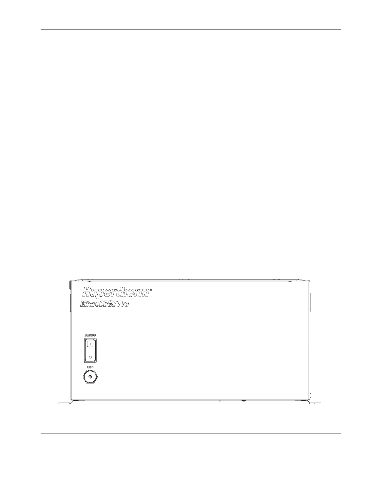
SpecificationS
Overview of MicroEDGE Pro
The controller is a PC-based CNC that uses Hypertherm’s Phoenix software to control one or more cutting or marking
systems.
Common features
The HyPath, Picopath, and SERCOS II and SERCOS III models of the MicroEDGE Pro CNC are configured with the
following types of communication ports:
• Serial ( 2 RS-232 and 2 RS-422)
• Ethernet (1)
• Hypernet (1)
• USB (5)
• Networking for part program download or remote diagnostic utilities
• Remote on/off interface
For more information about MicroEDGE Pro features, see System Specifications, in this section.
System options
MicroEDGE Pro features can be expanded with the addition of the following options that are available from Hypertherm
or your system integrator:
• LCD touchscreen monitor (with 1024 x 768 resolution and 4:3 aspect ratio) and 2 m (6 ft) cables for power, USB,
and VGA
• Touchscreen extension cable of up to 50 m (160 ft) for keyboard, video, and mouse
• Multiple drive axes
• Sensor THC or ArcGlide THC interface
• Analog joystick and speedpot interface
• Wireless card for Ethernet LAN
Front View of the MicroEDGE Pro CNC (all models)
MicroEDGE Pro Instruction Manual 807290 1-5
Page 40
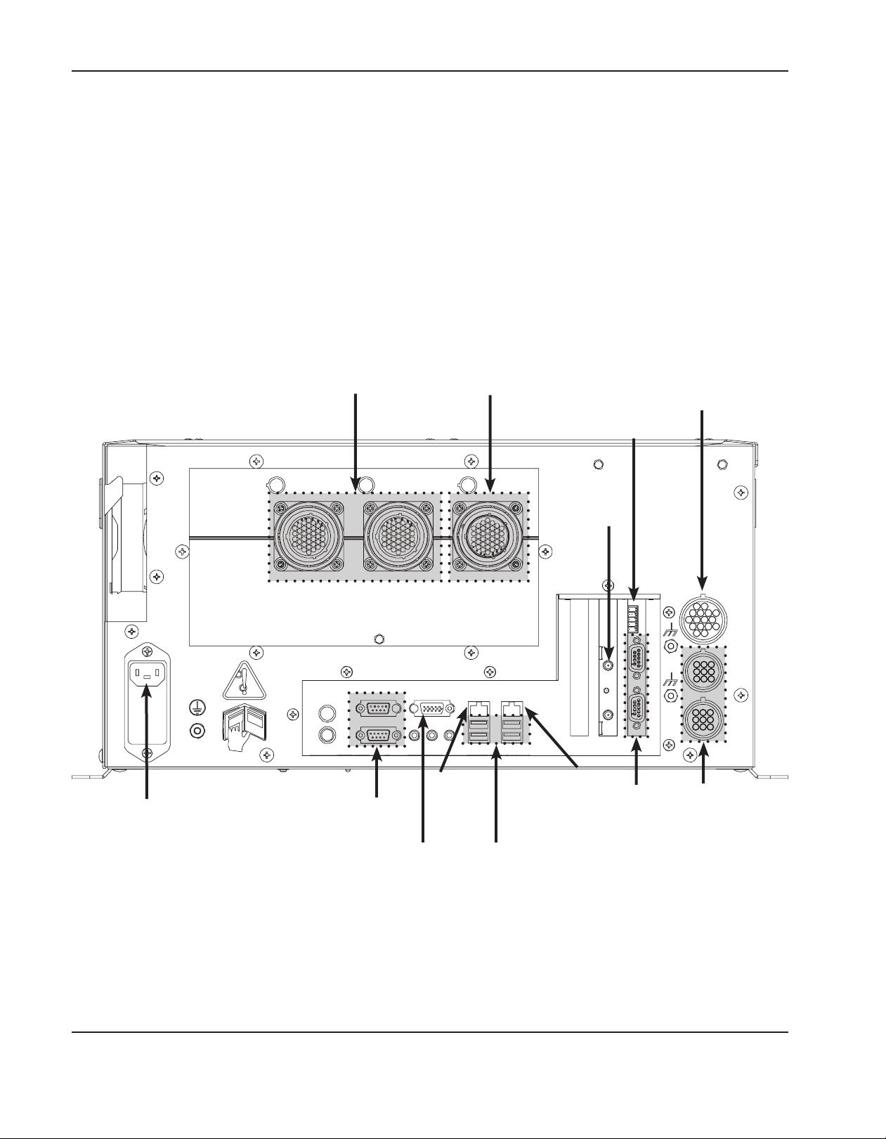
SpecificationS
Rear panel
The rear panel of the CNC has cable connectors for power, motion control feedback, I/O, and communication ports.
These connectors are clearly labeled with their function. There are four configurations available: HyPath, Picopath,
SERCOS II, and SERCOS III.
For more information about the electrical installation of the MicroEDGE Pro CNC, see Section 3, Installation.
Note: The rear panel shown below is for reference only. The rear panel on individual CNC units depends on which
configuration is ordered.
AC
power
input
Drive/encoder ports
Serial
ports on the
mother board
(RS-232)
VGA
port
LAN
port
I/O port
USB
ports
Remote On/Off
Antenna ports
for optional
wireless I/O
Hypernet
port
ports on the
serial isolation
(RS-422 or
RS-232)
Optional joystick and
speedpot port
Serial
board
Optional
SensorTHC
ports (2)
Rear panel of the Picopath MicroEDGE Pro CNC
1-6 MicroEDGE Pro Instruction Manual 807290
Page 41

System specifications
System Features
Processor Intel® Processor
Operating system Windows XPe
Software Phoenix version 9.7.1 or later
LAN ports 1 Ethernet port for general use
Hypernet Port 1 for communication with Hypernet-enabled systems
USB ports 5 USB 2.0 ports
SpecificationS
Serial ports
VGA port 1 standard 15-pin port for monitor
Onboard monitoring
devices
Hard drive SATA drive
THC support 2 Sensor THCs or 4 ArcGlide THCs (over Hypernet or discrete connections)
Certification cCSAus, CE, GOST-TR, c-Tick, UkrSEPRO
Configuration HyPath Picopath SERCOS II SERCOS III
Number of I/O 24/24 12/12 512/512 512/512
I/O Type
Axes available 2-4 2-4 2-12 2-12
Power
AC Input
Slow blow fuse 2 amp, 250 VAC
4 (2 RS-232 and 2 isolated RS-232/RS-422 configurable ports) with D-sub 9-pin
connectors
Hardware monitoring, including fan, CPU temperature, voltages, POST display
Input: positive logic
Output: contact
closure
• Voltage: 100 VAC to 240 VAC
• Current: 1.3 amps at 100 VAC / 0.6 amp at 240 VAC
• Frequency: 50/60 Hz
Input and output:
Negative logic
Fiber optic ring Ethernet
HyPath Picopath SERCOS II SERCOS III
DC available for I/O 24 V at 1.5 Amps 24 V at 1.5 Amps
Environmental
Temperature 0º C to 40º C (32º F to 104º F)
Humidity 50% relative humidity at 40º C, 90% relative humidity at 20º
Ingress Protection IP2X according to IEC 60529. Protect the equipment from exposure to excessive moisture.
Mechanical
Height 238 mm (9.38 in.)
Width 463 mm (18.22 in.)
Depth 332 mm (13.08 in.)
Weight 15.9 kg (35 lbs)
MicroEDGE Pro Instruction Manual 807290 1-7
Page 42

SpecificationS
Machine interface configurations
The CNC machine interface is the connection from the CNC to devices on the cutting table to achieve command motion
and to send or receive operational signals (I/O). The selection of a machine interface is based on the total number of
axes (motors) and I/O that you need for your application and that are supported by the CNC software. In addition to the
number of I/O signals required, the style of I/O should be considered to understand what devices and ratings you need
to operate external devices on the table, such as a Cut On signal or lifter station.
HyPath configuration
The HyPath interface is available in multiple configurations. The basic system offers 2 to 4 axes with 24inputs and
24outputs. The following table lists configuration options.
Part
Number
090118 2 24/24 No Yes No
090119 3 24/24 No Yes No
090120 4 24/24 No Yes No
090121 2 24/24 2 Yes Yes
090122 3 24/24 2 Yes Yes
090123 4 24/24 2 Yes Yes
Number
ofAxes
Number
of I/O
Integrated
Sensor THC
Wireless Analog
Rear panel of 090123
1-8 MicroEDGE Pro Instruction Manual 807290
Page 43

SpecificationS
Picopath configuration
The Picopath Interface offers 2 to 4 axes of motion control with 12 inputs and 12 outputs. This interface can be used to
retrofit an existing system with a compatible Picopath interface.
The Picopath interface can be configured to supply encoder power at 5 VDC, 12 VDC, or to supply externally
supplied (standalone) voltage encoders. See the circuit example in the Installation section that shows the Picopath I/O
connections.
Part
Number
090124 2 12/12 No No No
090125 2 12/12 2 No Yes
090126 2 12/12 No Yes No
090127 2 12/12 2 Yes Yes
090128 3 12/12 No No No
090129 3 12/12 2 No Yes
090130 3 12/12 No Yes No
090131 3 12/12 2 Yes Yes
090132 4 12/12 No No No
090133 4 12/12 2 No Yes
090134 4 12/12 No Yes No
090135 4 12/12 2 Yes Yes
Number
ofAxes
Number
of I/O
Integrated
Sensor THC
Wireless Analog
Rear panel of 090135
MicroEDGE Pro Instruction Manual 807290 1-9
Page 44

SpecificationS
SERCOS II configuration
SERCOS (SErial Real time COmmunication System) servo drive interface communicates with the drive amplifiers using
a fiber optic ring. SERCOS II replaces the traditional +/- 10 VDC analog output motion control card (MCC) with a fiber
optic driver card. This configuration allows you to expand your system and accommodate 12 axes and 512 I/O.
Notes:
• Multiple THC connections are available, as a function of SERCOS II.
• SERCOS II compatible (digital) drives must be used with this configuration.
• All SERCOS II MicroEDGE Pro configurations offer 512 I/O and wireless networking.
Part
Number
090107 2 Yes
090108 3 Yes
090109 4 Yes
090110 5 Yes
090111 6 Yes
090112 7 Yes
090113 8 Yes
090114 9 Yes
090115 10 Yes
090116 11 Yes
090117 12 Yes
Number
ofAxes
Wireless
Rear panel for all SERCOS II models
1-10 MicroEDGE Pro Instruction Manual 807290
Page 45

SpecificationS
SERCOS III configuration
SERCOS stands for SErial Real time COmmunication System servo drive interface. This approach to communication
with the drive amplifiers uses Ethernet and replaces the traditional +/- 10 VDC analog output motion control card
(MCC) with a driver card that manages SERCOS III, real-time transmissions and allows you to expand your system to
accommodate up to 12 axes and 512 I/O.
Notes:
• Multiple THC connections are available, as a function of SERCOS III.
• SERCOS III compatible (digital) drives must be used with this configuration.
• All SERCOS III MicroEDGE Pro configurations offer 512 I/O and wireless networking.
Part
Number
090172 2 Yes
090173 3 Yes
090174 4 Yes
090175 5 Yes
090176 6 Yes
090177 7 Yes
090178 8 Yes
090179 9 Yes
090180 10 Yes
090181 11 Yes
090182 12 Yes
Number
ofAxes
Wireless
Rear panel for all SERCOS III models
MicroEDGE Pro Instruction Manual 807290 1-11
Page 46

SpecificationS
Integrated Sensor THC
If your MicroEDGE Pro configuration includes the optional integrated Sensor THC, the CNC includes an analog input
for the HyPath and Picopath configuration and the following printed circuit boards (PCBs):
• Analog PCB (141125) for 1 to 2 Sensor THCs
• Breakout PCB (141210) for 1 to 2 Sensor THCs, 1 joystick, and 1 to 2 speedpots
• VDC3 PCB (141201) for 1 Sensor THC
For more information, see Installation.
Refer to the following Phoenix® software manuals for detailed information on the software that operates on the
MicroEDGE Pro CNC:
• Installation and Setup Manual (806410)
• Operator’s Manual (806400)
• Programmer’s Reference (806420)
THC1
THC2
1-12 MicroEDGE Pro Instruction Manual 807290
Page 47

SpecificationS
Secondary enclosure requirements
If the MicroEDGE Pro CNC is installed in a secondary enclosure, the secondary enclosure must maintain the
environmental specifications for operation that are listed in System specifications in this section. In particular, the
temperature within the primary MicroEDGE Pro enclosure must not exceed 60° C (140° F).
The addition of auxiliary cooling may be required to insure that the internal temperature of the MicroEDGE Pro enclosure
remains within the system specification.
Interior temperature
During operation, the temperature of the utility PCB (141194, 141222, 141256, 141307) within the enclosure must
remain below 60° C (140° F).
The temperature of the utility PCB is reported on the Control Information screen in Phoenix software. The utility PCB
temperature can also be displayed in the Watch Window. To add this temperature monitor to the Watch Window:
1. From the Main screen, choose Setups > Watch.
2. Select Temperature from the Lower Location dropdown list.
3. Choose OK.
Air circulation
A space of 5 cm (2 in) must be maintained on the top and on all sides between the primary and secondary enclosures to
allow air to circulate adequately around the MicroEDGE Pro chassis.
AC input
The range for AC power entering the enclosure must be maintained within 50/60 Hz, 100 – 240 VAC.
MicroEDGE Pro Instruction Manual 807290 1-13
Page 48

SpecificationS
1-14 MicroEDGE Pro Instruction Manual 807290
Page 49

Section 2
INSTALLATION
In this section:
Upon receipt ...............................................................................................................................................................................................2-3
Claims ...........................................................................................................................................................................................................2-3
Installation requirements...........................................................................................................................................................................2-3
Placement of system components .........................................................................................................................................................2-3
Mounting the CNC ....................................................................................................................................................................................2-4
Mounting hole patterns on the bottom of the CNC ................................................................................................................2-4
X and Y axis configuration .......................................................................................................................................................................2-5
AC power .....................................................................................................................................................................................................2-6
Power cable ......................................................................................................................................................................................2-6
Chassis grounding .....................................................................................................................................................................................2-7
Interface ports .............................................................................................................................................................................................2-8
Hypernet interface ...........................................................................................................................................................................2-8
LAN interface ....................................................................................................................................................................................2-8
USB interface (5) ............................................................................................................................................................................2-8
Serial ports (4) .................................................................................................................................................................................2-8
VGA Port 1 .......................................................................................................................................................................................2-8
Picopath connections ...............................................................................................................................................................................2-9
Picopath I/O connections ..............................................................................................................................................................2-9
Picopath I/O connector ..............................................................................................................................................................2-10
Picopath I/O circuit examples .................................................................................................................................................. 2-11
Picopath drive/encoder connectors ......................................................................................................................................... 2-12
Encoder voltage options on the Picopath interface ........................................................................................................................ 2-14
Encoder jumper options ..............................................................................................................................................................2-14
HyPath connections ............................................................................................................................................................................... 2-17
HyPath I/O .....................................................................................................................................................................................2-17
HyPath inputs ................................................................................................................................................................................ 2-18
HyPath outputs .............................................................................................................................................................................2-20
HyPath I/O connectors ...............................................................................................................................................................2-23
HyPath 4-axis servo connectors ............................................................................................................................................... 2-25
MicroEDGE Pro Instruction Manual 807290 2-1
Page 50

InstallatIon
Analog connections ................................................................................................................................................................................2-27
Sensor THC connector ............................................................................................................................................................... 2-27
THC cable specifications ........................................................................................................................................................... 2-28
Joystick and speedpot connector ............................................................................................................................................. 2-29
Joystick and speedpot cable adapter for MicroEDGE CNC (223252) .......................................................................... 2-30
SERCOS II I/O configuration ...............................................................................................................................................................2-31
SERCOS III I/O configuration ..............................................................................................................................................................2-32
SERCOS III Cable ....................................................................................................................................................................... 2-32
Serial port configuration ........................................................................................................................................................................ 2-33
Serial ports 1 and 2 ..................................................................................................................................................................... 2-33
Serial ports 3 and 4 ..................................................................................................................................................................... 2-33
Remote on/off cable ............................................................................................................................................................................... 2-35
Wireless network card ........................................................................................................................................................................... 2-36
Preparing to install the antenna .................................................................................................................................................2-36
Installing the antenna ................................................................................................................................................................... 2-36
Checking the wireless network in Windows .......................................................................................................................... 2-37
Mapping a network drive ............................................................................................................................................................2-38
Adding a folder in Phoenix .........................................................................................................................................................2-39
2-2 MicroEDGE Pro Instruction Manual 807290
Page 51

InstallatIon
Upon receipt
1. Verify that all the system components on your order have been received. Contact your supplier if any items are
missing.
• MicroEDGE Pro CNC
• AC power input cable (North America)
• AC power input cable connector (all other regions)
• Joystick and speedpot adapter cable for analog option
• MicroEDGE Pro CNC instruction manual
• Phoenix software instruction manuals (3)
2. Inspect the system components for any physical damage that may have occurred during shipping. If there is
evidence of damage, refer to Claims. All communications regarding claims must include the model number and
serial number located on the back of the CNC.
Claims
Claims for damage during shipment – If your unit was damaged during shipment, you must file a claim with the
carrier. Hypertherm will furnish you with a copy of the bill of lading upon request. If you need additional assistance, call
Customer Service listed in the front of this manual, or your authorized Hypertherm distributor.
Claims for defective or missing merchandise – If any of the merchandise is defective or missing, contact your
supplier. If you need additional assistance, call Hypertherm Customer Service (listed in the front of this manual) or your
authorized Hypertherm distributor.
Installation requirements
All installation and service of electrical systems must conform to national and local electrical codes. This work should be
performed only by qualified personnel.
Direct any technical questions to your authorized Hypertherm distributor or the nearest Hypertherm Technical Service
Department (listed in the front of this manual).
Placement of system components
• Place all system components in position prior to making electrical and interface connections.
• Ground all system components to earth. See Recommended grounding and shielding practices in this section for
details.
• Insure that the forced air ventilation opening is not blocked.
• Do not restrict operator access to the AC power connector for connection and disconnection of the power cord.
The AC power connector is the primary means for disconnection of power to the equipment.
MicroEDGE Pro Instruction Manual 807290 2-3
Page 52
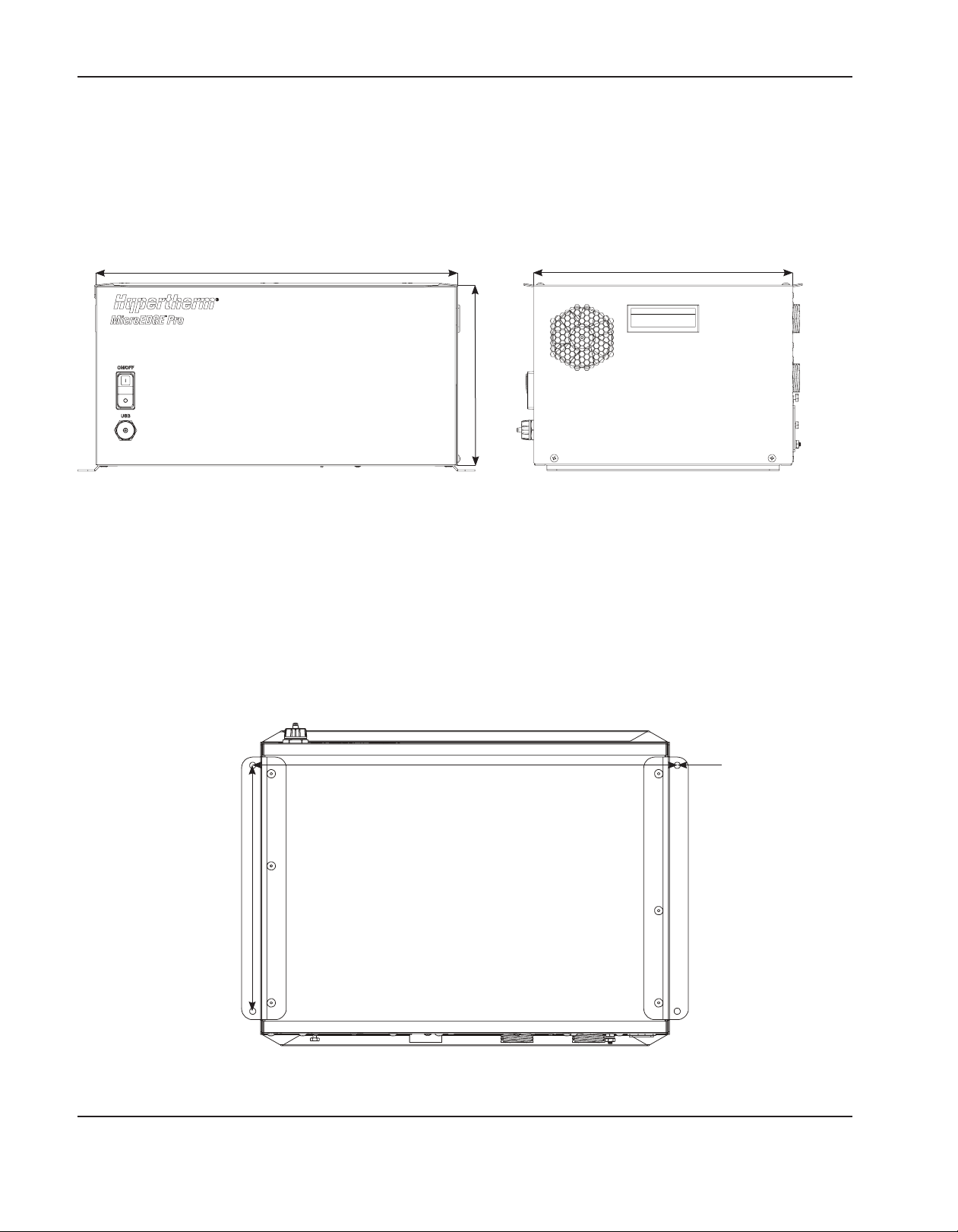
InstallatIon
Mounting the CNC
Before you configure the MicroEDGE Pro CNC, mount all system components using the appropriate instructions.
Do not allow the system components to lie unsecured on top of cabinets or on the floor.
463 mm
(18.22 in)
238 mm
9.38 in
332 mm
(13.08 in)
Front and Side Views of the MicroEDGE Pro CNC
Mounting hole patterns on the bottom of the CNC
If you are upgrading from a MicroEDGE CNC to a MicroEDGE Pro, the mounting bolt patterns are the same on both
systems.
483 mm
(19 in)
279 mm
(11 in)
.281 in. diameter for
1/4 in. or
6 mm bolts
MicroEDGE Pro mounting pattern
2-4 MicroEDGE Pro Instruction Manual 807290
Page 53

InstallatIon
X and Y axis configuration
To configure the X and Y axes, first decide which axis on the table will be the X axis and where the home position will be.
Next, define the X/Y orientation and home position in Phoenix software to match the configuration you want on the table.
The definition of the axes orientation and home position in software and on the table must agree so the system can
execute the part programs as expected.
X+
Y+
Y–
X–
Typical table origin and
Home position (0,0)
Example of a shape cutting system configured with an MicroEDGE Pro CNC
MicroEDGE Pro Instruction Manual 807290 2-5
Page 54

InstallatIon
AC power
Fuse size – 2 Amp, 250 V slow-blow
Ground nut and lock
AC Power
connector
Power cable
An AC power cable is standard equipment for North America, and is shipped with the MicroEDGE Pro CNC. For other
regions, the CNC is shipped with a power connector only to allow you to create a connector and cable combination that
meet the requirements of local code and power connections.
To create a power cable, use the plug (108842) that ships with the MicroEDGE Pro CNC and connect a 3-wire cable
for line, neutral, and ground signals according to local electrical codes. For more electrical specifications, see the Power
section of the System Specifications table in the Specifications section. Also see the drawings below for examples.
washer
#10-32
Note: The fuse block is universal and holds 1 fuse to comply with local electrical codes
Customer-supplied power
(without neutral)
L1 – line
L2 – line
PE ground
MicroEDGE Pro CNC
(as shipped)
Power entry
module
1 fuse: 2 amp,
5 x 20 mm or
0.25" x 1.25"
Customer-supplied power
(with neutral)
L1 – line
Neutral
PE ground
VAC input wiring examples
MicroEDGE Pro CNC
(as shipped)
Power entry
module
1 fuse: 2 amp,
5 x 20 mm or
0.25" x 1.25"
2-6 MicroEDGE Pro Instruction Manual 807290
Page 55
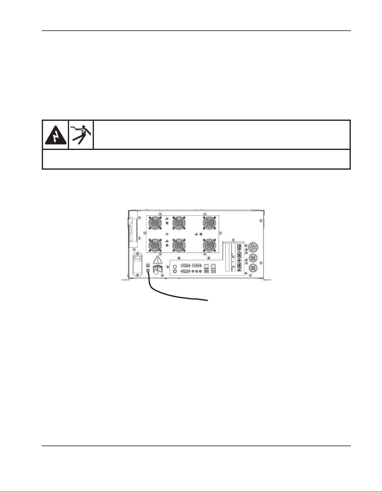
InstallatIon
Chassis grounding
The CNC must be properly grounded according to national and local electrical codes for safe operation. Use a
number6 AWG (16 mm2) wire between the ground stud on the rear of the CNC to the cutting table as shown below.
WARNING
ELECTRICAL SHOCK CAN KILL
This ground connection must be wired to insure safe and reliable operation.
To the star ground on the cutting table
Ground cable on the CNC
MicroEDGE Pro Instruction Manual 807290 2-7
Page 56

InstallatIon
Interface ports
Hypernet interface
The Hypernet interface allows a Hypernet connection to a Hypernet-enabled system, such as the ArcGlide THC.
LAN interface
The RJ-45 Ethernet interface allows the MicroEDGE Pro to connect to a local area network (LAN) for downloading
parts and using Remote Help.
For more information on LAN setup, see the Phoenix Software Installation and Setup Manual.
USB interface (5)
The USB 2.0 ports can be used to load programs or connect a USB keyboard, mouse, or touchscreen.
Serial ports (4)
The MicroEDGE Pro has 4 serial ports that use D-sub 9-pin connectors.
Two RS-232 serial ports (COM 1 and COM 2) are located on the motherboard.
Two more serial ports (COM 3 and COM 4) are located on all versions of the serial isolation board:
• 141222 for 4-axis HyPath and Picopath
• 141256 for 2-axis Picopath
• 141194/141307 for SERCOSII and SERCOS III
Transmission rate is up to 115K Baud. Both ports are preset with RS-422 as the default but both can be configured
for RS-232. For more information, see Serial port configuration in this section and in the Maintenance and Diagnostics
section.
VGA Port 1
The VGA port allows connection of an video monitor (touchscreen, LCD, or CRT).
2-8 MicroEDGE Pro Instruction Manual 807290
Page 57

InstallatIon
Picopath connections
Picopath I/O connections
I/O assignments are made in the Phoenix software on the Machine Setups > I/O screen. For more information, see the
Phoenix Software Installation and Setup Manual.
Rear view of the MicroEDGE Pro CNC with Picopath I/O configuration
Picopath I/O offers:
• 12 negative logic inputs rated at 24 VDC
• 12 negative logic outputs, rated at 24 VDC for up to 1 A loads
• 24 VDC field power supply on the Picopath PCB with a total usage of 1.5 A
MicroEDGE Pro Instruction Manual 807290 2-9
Page 58

InstallatIon
Picopath I/O connector
Use the following information to create Picopath I/O cables.
The Picopath I/O mating connector is a 37-pin circular connector:
• Cable connector AMP #208470-1
• Sockets contacts: AMP 66101-3 (16–18 ga), AMP 66105-3 (20–24 ga)
• Hypertherm kit: 228490
Pin no. Signal
1 Input 1
2 Input 2
3 Input 3
4 Input 4
6 Input 6
8 Input 8
9 Input 9
10 Input 10
11 Input 11
12 Input 12
13 N/C
14 +24 VDC
15 +24 VDC
16 N/C
17 24 V Common
18 24 V Common
19 N/C
20 N/C
21 Output 1
22 Output 2
23 Output 3
24 Output 4
25 Output 5
26 Output 6
27 Output 7
28 Output 8
29 Output 9
30 Output 10
31 Output 11
32 Output 12
33 I/O Shield
34 +24 VDC
35 +24 VDC
36 24 V Common
37 24 V Common
16
10
5
1
4
9
15
23
28
29
33
34
37
22
Picopath I/O connector J8
Z/W AXIS
DRV/ENC
Picopath I/O connector
X/Y AXIS
DRV/ENC
I/O
2-10 MicroEDGE Pro Instruction Manual 807290
Page 59

Picopath I/O circuit examples
+5 VDC
+24 VDC
Input
Common
Shield
InstallatIon
Switch
(normally open)
37
Customer supplied cable
FET
+24 VDC
MicroEDGE Pro
Input
Common
Shield
37
Customer circuit
Input – CNC sinking
24 VDC coil
with diode
Customer supplied cable
MicroEDGE Pro
Customer circuit
Output, 24 VDC coil – CNC sinking
MicroEDGE Pro Instruction Manual 807290 2-11
Page 60

InstallatIon
Picopath drive/encoder connectors
Picopath axis assignments are made in Phoenix software on the Machine Setups > Axis screen. For more information,
see the Phoenix Software Installation and Setup Manual.
Use the following information to create Picopath drive/encoder cables.
The Picopath drive/encoder mating connector is a 37-pin, circular connector:
• Cable connector: AMP #208472-1
• Pin contacts AMP 66099-3 (16–18 ga), AMP 66103-3 (20–24 ga)
• Cabling: Belden # 9504 or equivalent for encoder signals
• Cabling: Belden # 9501 or equivalent for drive signals
• Hypertherm kit: 228489
Notes:
• Enable individual drives for each axis for proper operation.
• Connect cable shields to the metal shell of the connector for optimum noise immunity and to keep signal commons
separate from the ground.
16
22
23
28
29
33
34
37
10
5
1
4
9
15
Picopath drive/encoder
connector J6 and J7
J6
Z/W AXIS
DRV/ENC
Picopath drive/encoder connectors
J7
X/Y AXIS
DRV/ENC
I/O
2-12 MicroEDGE Pro Instruction Manual 807290
Page 61

Picopath pin-outs for servo drive connectors
Connector J6
Pin no. for
Z Axis
2 2 +5 VDC or +12 VDC sourced for encoder power
3 3 Encoder power common
4 1 Encoder power output (available if needed)
7 7 Encoder power shield
8 6 Encoder power common (available if needed)
9 5 Encoder channel A input
14 11 Encoder channel /A Input
15 10 Encoder channel B Input
21 17 Encoder channel /B Input
22 16 Encoder channel Z Input
28 23 Encoder channel /Z Input
13 12 Encoder shields
24 26 Drive enable in (relay contact closure)
25 27 Drive enable out (relay contact closure)
37 34 Drive power input (+12 VDC or +15 VDC)
33 29 Servo output (± 10 VDC)
32 30 Drive power common
36 35 Drive power input (–12 VDC or –15 VDC)
20 18 Servo output common
19 31 Drive/servo shield
Pin no. for
W Axis
Signal
InstallatIon
Connector J7
Pin no. for
X Axis
2 2 +5 VDC or +12 VDC sourced for encoder power
3 3 Encoder power common
4 1 Encoder power output (available if needed)
7 7 Encoder power shield
8 6 Encoder power common (available if needed)
9 5 Encoder channel A input
14 11 Encoder channel /A Input
15 10 Encoder channel B Input
21 17 Encoder channel /B Input
22 16 Encoder channel Z Input
28 23 Encoder channel /Z Input
13 12 Encoder Shields
24 26 Drive enable in (relay contact closure)
25 27 Drive enable out (relay contact closure)
37 34 Drive power input (+12 VDC or +15 VDC)
33 29 Servo output (± 10 VDC)
32 30 Drive power common
36 35 Drive power input (–12 VDC or –15 VDC)
20 18 Servo output common
19 31 Drive/servo shield
Pin no. for
Y Axis
Signal
Note: See the jumpers on the Picopath
4-axis backdoor interface board to select
one of the following:
• 5 VDC sourced encoder power
(default).
• 12 VDC sourced encoder power.
• Customer supplied encoder and field
power.
For more information, see Maintenance
and Diagnostics.
MicroEDGE Pro Instruction Manual 807290 2-13
Page 62

InstallatIon
Encoder voltage options on the Picopath interface
The Picopath interface in the MicroEDGE Pro is similar to and compatible with the Picopath interface in an EDGE or
MicroEDGE CNC except that the MicroEDGE Pro Picopath interface provides jumper settings that allow the user to
select how the field power supply voltages are routed on the board.
The jumper is set to 5 VDC sourced encoder power in the factory and uses the MicroEDGE Pro internal field power
supply to power the encoder, analog, and 24 I/O circuits.
The drive/encoder and I/O connections on the back of the Picopath interface provide voltages that you can use to
power an external encoder, provide analog power to a drive, or provide DC power for the cutting system’s I/O.
Encoder power is frequently used in DC drive systems because the motors’ encoder is usually wired directly to the
drive/encoder connector of the CNC. Most modern encoders use 5 VDC for power while older cutting systems use
12VDC for encoder power. The jumper blocks on the MicroEDGE Pro Picopath interface allow you to replace an older
CNC with the MicroEDGE Pro CNC without having to replace encoders or to rewire the drive circuit of the cutting
system.
Encoder jumper options
The encoder jumper blocks allow you to chose between 5 V encoders, 12 V encoders, or to supply external voltages to
the MicroEDGE Pro. The jumper must be installed on one of these encoder jumper blocks.
5 V sourced encoders use the MicroEDGE Pro internal field power supply to provide 5 VDC on pin 2 of each
drive/ encoder connector to power an external encoder. It also puts 5 VDC on the pull-up resistor for each encoder input
signal. This voltage should match the signal voltage of the encoder channels.
12 V sourced encoders use the MicroEDGE Pro internal field power supply to provide 12 VDC on pin 2 of each
drive/ encoder connector to power an external encoder. It also puts 12 VDC on the pull-up resistor for each encoder
input signal. This voltage should match the switching voltage of the motor’s encoder.
External encoder voltage provides the MicroEDGE Pro with field power to supply encoder power (5 VDC or 12 VDC),
voltage on the pull-up resistor on the encoder channel, drive analog power (+/- 12 VDC), and I/O power (24 VDC) to
the Picopath interface. This option is common when a MicroEDGE Pro CNC is replacing a CNC that did not have an
internal field power supply (D80).
2-14 MicroEDGE Pro Instruction Manual 807290
Page 63

J13
!
12 V encoder
power (out)
InstallatIon
J12
J12
5 V encoder
power (out)
+5Vf
J14
External encoder, drive
and I/O voltage
J3
Encoder jumper blocks on the Picopath interface
+Ve +Va -Va
+12Vf -12Vf +24Vf
1
3
5
J12
5 V encoder power (out)
Default setting, shown with
jumper
+24Vf
7
/AXISWDOG_HDR
/AXISWDOG
9
J13
J13
12 V
encoder
power (out)
J14
J14
External
encoder,
drive, and I/O
voltage
MicroEDGE Pro Instruction Manual 807290 2-15
+12Vf
Encoder power (in)
2
1
2
4
3
4
6
5
6
8
7
8
10
9
10
1
2
+ Drive power (in)
3
4
5
6
- Drive power (in)
Circuit layout of the jumper blocks
7
8
I/O power (in)
9
10
Page 64

InstallatIon
The following illustration shows an encoder circuit in which the jumper setting puts voltage on Ve which supplies voltage
to the pull-up resistor on the encoder channels. The Ve voltage should equal the voltage on the encoder channel.
Refer to the instruction manual for your encoder to verify the encoder channel voltage or contact your table supplier.
Ve
From drive/encoder connectors
Encod e r Chan ne l A
Encoder channel A
Encod e r Chan ne l /A
Encoder channel /A
1
2 7
8
Ve
1 2
Ve
1 2
+5Vf
4
3
+
6
-
1
+5Vf
Encod e r Chan ne l B
Encoder channel B
Encod e r Chan ne l // B
Encoder channel /B
3 6
Ve
1 2
4 5
11
13
1 2
Encoder circuit with jumper settings for voltage on encoder channels
10
+
8
-
2-16 MicroEDGE Pro Instruction Manual 807290
Page 65

InstallatIon
HyPath connections
HyPath I/O
The HyPath I/O PCB provides 24 inputs and 24 outputs through four circular plastic connectors (CPCs), each
containing 6 inputs and 6 outputs.
HyPath I/O assignments are made in Phoenix software, on the I/O Setup screen. For more information, see the Phoenix
Software Installation and Setup Manual.
View of the MicroEDGE Pro CNC with HyPath 24 I/O, 4-axis servo configuration and 2 Sensor THCs
MicroEDGE Pro Instruction Manual 807290 2-17
Page 66
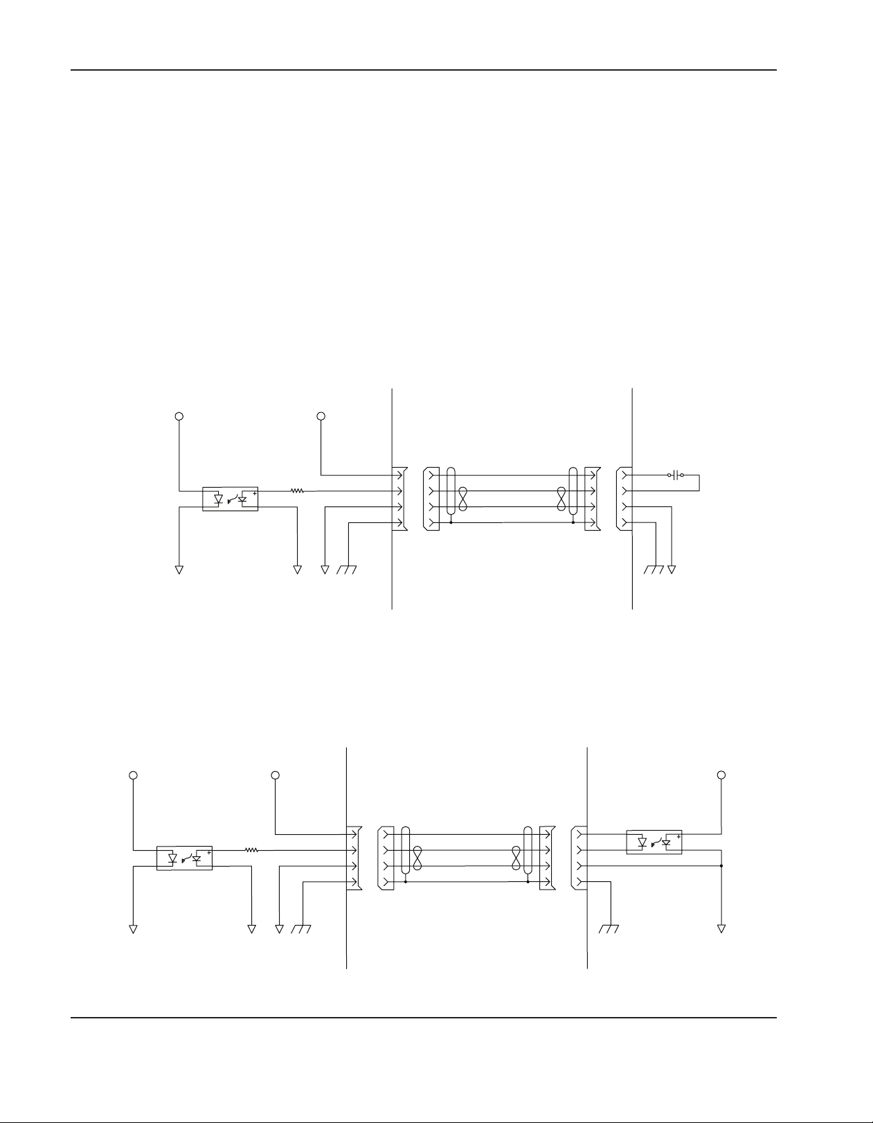
InstallatIon
HyPath inputs
• Use positive logic that requires a positive voltage to activate the input.
• Are opto-coupled and have a range of +4.7 V minimum to +32 V maximum. Internal series resistor = 4.7 K Ohm.
• +24 VDC field power supply on the HyPath and 4-axis servo PCB with a total external usage of 1.5 A.
HyPath input circuit examples
• Connection to a limit switch, a push-button switch, a home switch, a station select switch (toggle switch), a relay
contact, or an emergency-stop button
+5 VDC +24 VDC
4.7 k
MicroEDGE Pro
Input
Common
Shield
37
Customer supplied cable
Customer-supplied, normally open switch
• Connection to a opto-isolator, typically found in a THC and a plasma supply.
+5 VDC +24 VDC
4.7 k
Input
Common
Shield
37
Customer supplied cable
Customer circuit
VDC
MicroEDGE Pro
Customer circuit
Customer-supplied opto-isolator switch
2-18 MicroEDGE Pro Instruction Manual 807290
Page 67
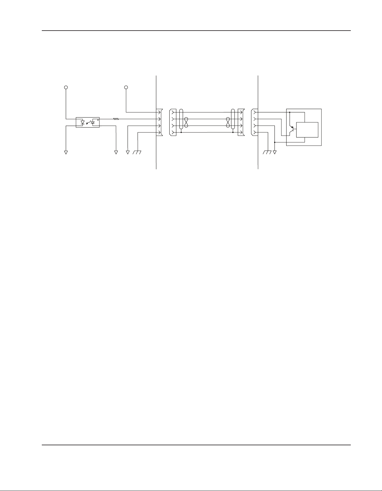
• Typical connection to a PNP-style proximity sensor input (PNP)
+5 VDC +24 VDC
InstallatIon
4.7 k
MicroEDGE Pro
Customer supplied proximity switch – PNP sourced
Input
Common
Shield
37
Control
circuit
Customer supplied cable
Customer circuit
MicroEDGE Pro Instruction Manual 807290 2-19
Page 68

InstallatIon
HyPath outputs
• Use relay contact closure (003179). The relay outputs are normally open contacts. Outputs can be set to normally
closed by setting the output logic in the I/O screen in the Phoenix software.
• 5 V to 32 V switching voltage; 5 A continuous-resistive load; 2 A continuous-inductive load.
HyPath output circuit examples
Connection to a relay coil (1a, 1b, and 1c). Notice that the commons are connected together and a diode (supplied by
the customer) is used between DC coil connections.
1a.
+24 VDC
1b.
Relay
003179
Relay
003179
MicroEDGE Pro
+24 VDC
Output A
Output B
Common
Output A
Output B
Common
Shield
Shield
VAC
AC coil
37
Customer supplied cable
Customer circuit
AC coil – supplied by customer
24 VDC coil, with
diode
37
Customer supplied cable
MicroEDGE Pro
Customer circuit
24 VDC coil – CNC sourced
2-20 MicroEDGE Pro Instruction Manual 807290
Page 69
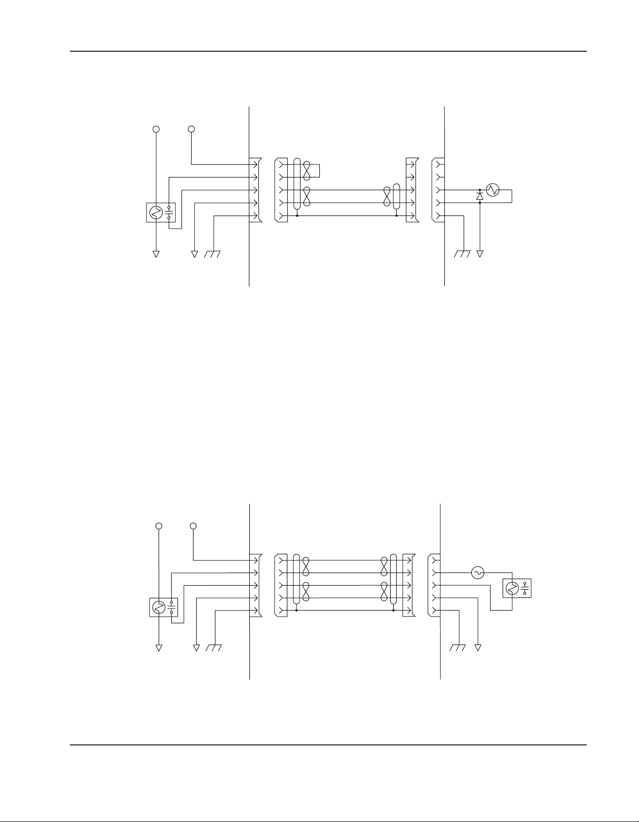
1c.
InstallatIon
+24 VDC
Output A
Output B
Relay
003179
MicroEDGE Pro
Common
Shield
37
Customer supplied cable
24 VDC coil – CNC sourced
Connection to a relay coil (2a and 2b). The field voltage is supplied by the customer.
24 VDC coil,
with diode
Customer circuit
2a.
+24 VDC
VAC
AC relay
Customer circuit
Relay
003179
Output A
Output B
Common
MicroEDGE Pro
Shield
37
Customer supplied cable
AC relay – supplied by customer
MicroEDGE Pro Instruction Manual 807290 2-21
Page 70
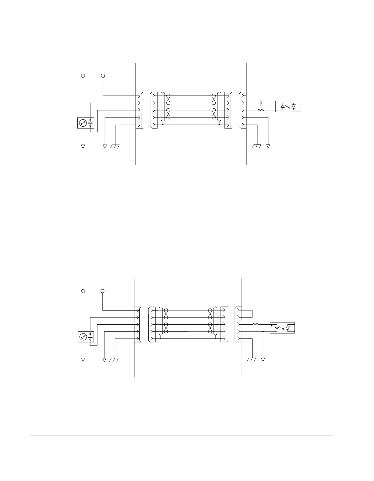
InstallatIon
2b.
+24 VDC
Output A
Output B
Relay
003179
MicroEDGE Pro
Common
Shield
37
Customer supplied cable
Opto-relay – supplied by customer
3. Typical connection to an opto-isolator. The input is typical for a THC or PAC System.
VDC
Opto-relay
Customer circuit
+24 VDC
VDC
Opto-relay
Customer circuit
Relay
003179
Output A
Output B
Common
MicroEDGE Pro
Shield
37
Customer supplied cable
Opto-relay – CNC sourced
2-22 MicroEDGE Pro Instruction Manual 807290
Page 71
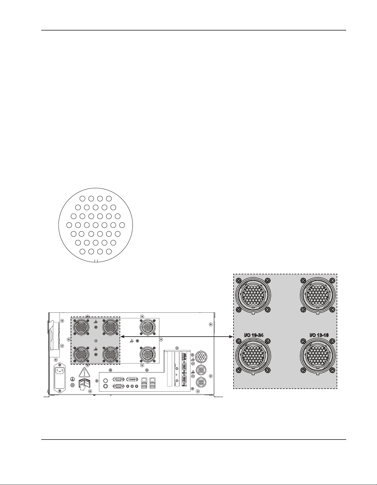
InstallatIon
HyPath I/O connectors
Notes:
• Isolate all external commons from the chassis ground.
• If external voltage is used to activate I/O, connect the external source’s common to the internal +24 V common.
• HyPath systems have the I/O for each connector printed above the connectors.
Use the following information to create HyPath I/O cables.
The HyPath I/O mating connector is a 37-pin, circular connector:
• Cable connector: AMP 206305-1
• Pin contacts: AMP 66098 (16–18 AWG), AMP 66331 (20–24 AWG)
• Hypertherm kit: 228492
The following pages provide additional specifications and pinout information for the HyPath interface boards.
34
29
23
16
10
5
1
HyPath I/O connector
37
33
28
22
15
9
4
J6 I/O 7-12 J7 I/O 1-6
J5 I/O 13-18J4 I/O 19-24
HyPath I/O connectors
Location of the I/O connectors
MicroEDGE Pro Instruction Manual 807290 2-23
Page 72

InstallatIon
HyPath I/O pin-outs
Connector J7 – I/O 1 to 6
Pin no. Inputs Pin no. Outputs
1 +24 VDC Source 19 +24 VDC Source
2 Input 1 20 Output 1A
3 Common 21 Output 1B
4 +24 VDC Source 22 +24 V Field
5 Input 2 23 Output 2A
6 Common 24 Output 2B
7 +24 VDC Source 25 +24 V Field
8 Input 3 26 Output 3A
9 Common 27 Output 3B
10 +24 VDC Source 28 +24 V Field
11 Input 4 29 Output 4A
12 Common 30 Output 4B
13 +24 VDC Source 31 +24 V Field
14 Input 5 32 Output 5A
15 Common 33 Output 5B
16 +24 VDC Source 34 +24 V Field
17 Input 6 35 Output 6A
18 Common 36 Output 6B
37 Shield
Connector J6 – I/O 7 to 12
Pin no. Inputs Pin no. Outputs
1 +24 VDC Source 19 +24 VDC Source
2 Input 7 20 Output 7A
3 Common 21 Output 7B
4 +24 VDC Source 22 +24 V Field
5 Input 8 23 Output 8A
6 Common 24 Output 8B
7 +24 VDC Source 25 +24 V Field
8 Input 9 26 Output 9A
9 Common 27 Output 9B
10 +24 VDC Source 28 +24 V Field
11 Input 10 29 Output 10A
12 Common 30 Output 10B
13 +24 VDC Source 31 +24 V Field
14 Input 11 32 Output 11A
15 Common 33 Output 11B
16 +24 VDC Source 34 +24 V Field
17 Input 12 35 Output 12A
18 Common 36 Output 12B
37 Shield
Connector J5 – I/O 13 to 18
Pin no. Inputs Pin no. Outputs
1 +24 VDC Source 19 +24 VDC Source
2 Input 13 20 Output 13A
3 Common 21 Output 13B
4 +24 VDC Source 22 +24 V Field
5 Input 14 23 Output 14A
6 Common 24 Output 14B
7 +24 VDC Source 25 +24 V Field
8 Input 15 26 Output 15A
9 Common 27 Output 15B
10 +24 VDC Source 28 +24 V Field
11 Input 16 29 Output 16A
12 Common 30 Output 16B
13 +24 VDC Source 31 +24 V Field
14 Input 17 32 Output 17A
15 Common 33 Output 17B
16 +24 VDC Source 34 +24 V Field
17 Input 18 35 Output 18A
18 Common 36 Output 18B
37 Shield
Connector J4 – I/O 19 to 24
Pin no. Inputs Pin no. Outputs
1 +24 VDC Source 19 +24 VDC Source
2 Input 19 20 Output 19A
3 Common 21 Output 19B
4 +24 VDC Source 22 +24 V Field
5 Input 20 23 Output 20A
6 Common 24 Output 20B
7 +24 VDC Source 25 +24 V Field
8 Input 21 26 Output 21A
9 Common 27 Output 21B
10 +24 VDC Source 28 +24 V Field
11 Input 22 29 Output 22A
12 Common 30 Output 22B
13 +24 VDC Source 31 +24 V Field
14 Input 23 32 Output 23A
15 Common 33 Output 23B
16 +24 VDC Source 34 +24 V Field
17 Input 24 35 Output 24A
18 Common 36 Output 24B
37 Shield
2-24 MicroEDGE Pro Instruction Manual 807290
Page 73

InstallatIon
HyPath 4-axis servo connectors
The HyPath 4-axis servo PCB provides the drive and encoder connections for up to 4 independent servo axes.
The board provides two circular connectors. Each connector provides connections for two independent servo axes.
Axis assignments are made in Phoenix software on the Axes screen. For more information, see the Phoenix Software
Installation and Setup Manual.
HyPath servo connector
Use the following information to create HyPath servo cables.
The HyPath servo connector is a 37-pin, circular connector:
• Cable connector: AMP 206150-1
• Socket contacts: AMP 164164 (16–18 AWG), AMP 164163 (20–24 AWG)
• Hypertherm kit: 228491
J3 Axes 1-2
J4 Axes 3-4
Location of the 4-axis servo connectors
HyPath servo
connectors
MicroEDGE Pro Instruction Manual 807290 2-25
Page 74

InstallatIon
Drive/Encoder pin-outs
Notes:
• Z Channel is the marker pulse channel which is 1 pulse/revolution.
• Not all axes may be available. Verify how many axes are available on your CNC in the
Diagnostics > Control Information screen in Phoenix software.
HyPath servo connectors J3, J4
22
15
28
33
37
34
29
23
16
9
4
10
5
1
Connector J3 (Axes 1 and 2)
Pin no.
for Axis 1
Pin no.
for Axis 2
Signal
1 20 Axis shield
2 21 Encoder +5 V out
3 22 Encoder common
4 23 Encoder +12 V out
5 24 Encoder common
6 25 Encoder +24 V out
7 26 Encoder common
8 27 Encoder Axis A
9 28 Encoder Axis A\
10 29 Encoder Axis B
11 30 Encoder Axis B\
12 31 Encoder Axis Z
13 32 Encoder Axis Z\
14 33 Axis enable A
15 34 Axis enable B
16 35 Axis servo output
17 36 Analog common
18 37 Axis shield
19 Shield
Connector J4 (Axes 3 and 4)
Pin no.
for Axis 3
Pin no.
for Axis 4
Signal
1 20 Axis shield
2 21 Encoder +5 V out
3 22 Encoder common
4 23 Encoder +12 V out
5 24 Encoder common
6 25 Encoder +24 V out
7 26 Encoder common
8 27 Encoder Axis A
9 28 Encoder Axis A\
10 29 Encoder Axis B
11 30 Encoder Axis B\
12 31 Encoder Axis Z
13 32 Encoder Axis Z\
14 33 Axis enable A
15 34 Axis enable B
16 35 Axis servo output
17 36 Analog common
18 37 Axis shield
19 Shield
The following illustration shows the axis-enable relay contacts for each axis on the 4-axis servo board.
A
Customer
4
B
3
1
CNC
2
Relay SPST
HyPath 4-axis servo – axis enable output relay contacts
2-26 MicroEDGE Pro Instruction Manual 807290
Page 75

InstallatIon
Analog connections
The MicroEDGE Pro CNC includes connectors for the Sensor THC, as well as a joystick and speedpot so that a table
manufacturer can add these features.
Sensor THC connector
In configurations with integrated Sensor THCs, the MicroEDGE Pro has dedicated connectors for THC 1, and THC 2.
Notes:
• Analog inputs for the speed pots are rated at 0 to +10 VDC.
• Connect cable shields to the external PE studs for optimum noise
immunity.
• The Series 1 PCI analog card is named PCI-AIC Rev X on the CNC
3
7
11 12 13 14
15
Information Diagnostic screen in the Phoenix software
THC connector:
• Cable connector: AMP 206708-1
• Pin contacts: AMP 65105-3
1
4
7
• Cabling: Belden # 9540 or equivalent for encoder signals
• Hypertherm kit: 228495
1 2
4
7
Pin-outs for Integrated Sensor THC 1 and 2 connectors
Pin no. CNC I/O configuration Signal
1 Common Common
2 Input + Nozzle Contact Sense + ( relay contact )
3 Input - Nozzle Contact Sense - ( relay contact )
4 Output + Nozzle Contact Enable + ( relay contact )
5 Output - Nozzle Contact Enable - ( relay contact )
6 Analog input + THC +
7 Analog input - THC 8 Output + Hold Ignition ( relay contact )
9 Output - Hold Ignition ( relay contact )
Connector ground Shield
2
1
4
6
5
8
9
10
Joystick and speedpot
interface
16
2
3
5 6
8
5
8
9
3
6
9
THC 1 interface
THC 2 interface
MicroEDGE Pro Instruction Manual 807290 2-27
Page 76

InstallatIon
THC cable specifications
The following tables provide the pin-out details for the connectors on the Sensor THC amplifier, the MicroEDGE Pro
CNC, and the voltage divider board (VDC3). Use these tables to manufacture the cables that connect these devices in
your configuration.
Pin-outs for voltage divider board 3 (VDC3) connectors
J1 Power connector on VDC3
Pin no. Signal
1 120 VAC line
2 120 VAC neutral
J3 Field connector on VDC3 (black terminal strip)
Pin no. Signal
1 EMI Ground
2 Electrode (connection to negative connection inside plasma system)
3 Work (connection to the positive connection inside the plasma system)
4 No connection
6 Ohmic contact wire connection
Pin-out for the cable between J2 on VDC3 and THC 1 on the CNC
J2 I/O Connector on VDC3 THC1 Connector on the CNC
Pin no. Signal Pin no. Outputs
1 24 VDC common (out) 1 24 VDC Common (in)
2 +24 VDC (out) 2 Nozzle Contact Sense +
3 Nozzle contact sense (output) 3 Nozzle Contact Sense 4 Nozzle contact enable (input) 4 Nozzle Contact Enable +
5 24 VDC common (out) 5 Nozzle Contact Enable 6 + Analog out 6 + Analog in
7 - Analog out 7 - Analog in
8 Chassis ground (cable shield)
8 Hold +
9 Hold -
J1
J2
J3
Voltage divider board (141201)
2-28 MicroEDGE Pro Instruction Manual 807290
Page 77

Joystick and speedpot connector
• Cable connector: AMP 206037-1
• Pin contacts AMP 65105-3
• Cabling: Belden # 8308 or equivalent for encoder signals
• Hypertherm kit: 228837
Pin-outs for joystick and speedpot connector
Pin no. Signal
1 Joystick up
2 Joystick down
3 Joystick left
4 Joystick right
5 Common
6 10 V reference
7 Speed pot 1+
8 Speed pot 1-
9 Common
10 10 V reference
11 Speed pot 2+
12 Speed pot 2-
13 Common
14 Common
15 Common
16 Common
InstallatIon
MicroEDGE Pro Instruction Manual 807290 2-29
Page 78

InstallatIon
Joystick and speedpot cable adapter for MicroEDGE CNC (223252)
If the MicroEDGE Pro CNC is replacing a Hypertherm MicroEDGE CNC, an adapter cable is required to allow the cable
for the MicroEDGE joystick and speedpot to connect to the MicroEDGE Pro.
Side A
Connect to the MicroEDGE joystick and
speedpot cable
1 3
2
64
5
7 9
8
Side A Pin no. Wire color Signal Side B Pin no.*
1 Black Joystick up 1
2 White Joystick down 2
3 Red Joystick left 3
4 Green Joystick right 4
5 Brown Common 5
6 Blue Speed pot 1+ 7
7 Orange Speed pot 1- 8
8 Yellow Speed pot 2+ 11
9 Purple Speed pot 2- 12
Side B
Connect to the MicroEDGE Pro joystick and
speedpot connector
2 1
4
12
3
7
8
11
5
*On Side B, there are no connections on pins 6,10 and 13 to 16.
2-30 MicroEDGE Pro Instruction Manual 807290
Page 79

InstallatIon
SERCOS II I/O configuration
The MicroEDGE Pro SERCOS II I/O configuration conforms to the SERCOS II standard. The full details of this
specification cannot be addressed in this manual. For complete of SERCOS technology and specifications, refer to:
http://www.sercos.com.
Rear view of the SERCOS II MicroEDGE Pro CNC
MicroEDGE Pro Instruction Manual 807290 2-31
Page 80
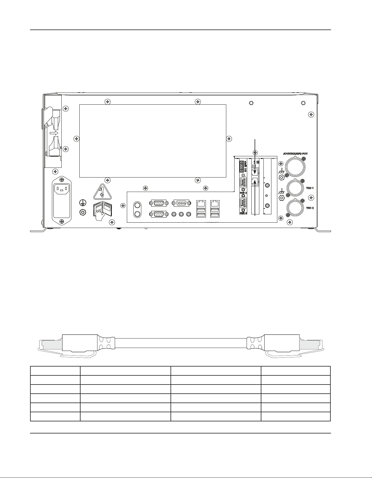
InstallatIon
SERCOS III I/O configuration
The MicroEDGE Pro SERCOS III I/O configuration conforms to the SERCOS III standard. The full details of this
specification cannot be addressed in this manual. Refer to the Phoenix Software V9 Series Installation and Setup
Guide (806410) for instructions about how to set up your EDGE Pro SERCOS III CNC. For complete information about
SERCOS technology and specifications, refer to: http://www.sercos.com.
Port 1
Port 2
Rear view of the SERCOS III MicroEDGE Pro CNC
SERCOS III Cable
A shielded Cat-5e Ethernet cable connects the SERCOS III I/O interface on the rear of the CNC enclosure to the
drive amplifier cabinet. A minimum of one cable is required for this connection to create a single SERCOS III line that
connects Port 1 (P1) on the CNC and all the SERCOS III drives in the drive amplifier cabinet.
To create a SERCOS III ring that will provide communication redundancy and security, connect a second cable
between Port 2 (P2) on the CNC and the drive amplifier cabinet.
Part number Length Part number Length
223212 3.0 m (10 ft) 223099 23.0 m (75 ft)
223222 6.0 m (20 ft) 223100 30.5 m (100 ft)
223119 7.5 m (25 ft) 223101 45.5 m (150 ft)
223223 10.5 m (35 ft) 223102 61.0 m (200 ft)
223008 15.0 m (50 ft)
2-32 MicroEDGE Pro Instruction Manual 807290
Page 81

InstallatIon
Serial port configuration
The serial ports in the MicroEDGE Pro are designed to operate with a standard 9-pin serial port connector. The
following list provides specifications for these ports. For more information, see the Phoenix Software Installation and
Setup manual.
Serial isolation specifications (see Machine Setups > Ports In Phoenix software)
Channel Type Optically isolated RS-422 or RS-232
Information Code ASCII
Baud Rate User-selectable up to 115.2K baud
Number of Start Bits 1
Number or Stop Bits 1
Word Length User-selectable 7 or 8 bits
Parity User-selectable none, even or odd
Data Synchronization XON (Control-Q) / XOFF (Ctrl/S)
Time Out User-selectable in one-second increments
Transmit Delay User-selectable in 0.01-second increments
Rear Panel Connector IBM-PC/AT compatible 9-pin D-type female
Serial ports 1 and 2
The default configuration for serial ports 1 and 2 on the motherboard is RS-232. These ports cannot be reconfigured.
Serial ports 3 and 4
Both serial ports on the following boards are shipped in the RS-422 wiring configuration:
• HyPath and Picopath 4-axis MCC, utility, and serial isolation board (141222)
• Picopath 2-axis MCC, utility, and serial isolation board (141256)
• SERCOS II and SERCOS III utility and serial isolation board
(141194/141307)
To change either port to an RS-232 configuration, you must find the jumper
for the appropriate port and move the jumper from the RS-422 position to the
RS-232 position. These positions are clearly marked on the board.
Configure the port for RS-232 operation before connecting RS-232 compatible
devices.
Serial port
3
Serial port
4
RS-422
RS-232
Jumpers in
RS-422 position
RS-422
RS-232RS-232
MicroEDGE Pro Instruction Manual 807290 2-33
Page 82

InstallatIon
CNC RS-422 DB-9 Pin-out
Pin no. Signal Name Description
1 Shield Chassis ground
2 TxD- Transmit data - to external device
3 RxD- Receive data - from external device
4 TxD+ Transmit data + to external device
5 Common Ground
6 No connection
7 RxD+ Receive data + from external device
8 No connection
9 No connection
CNC RS-232 DB-9 Pin-out (reference only)
Pin
Signal Name Description
no.
1 Shield Chassis ground
2 TxD Transmit data to external device
3 RxD Receive data from external device
4 No connection
5 Common Ground
6 No connection
7 No connection
8 No connection
9 No connection
2-34 MicroEDGE Pro Instruction Manual 807290
Page 83
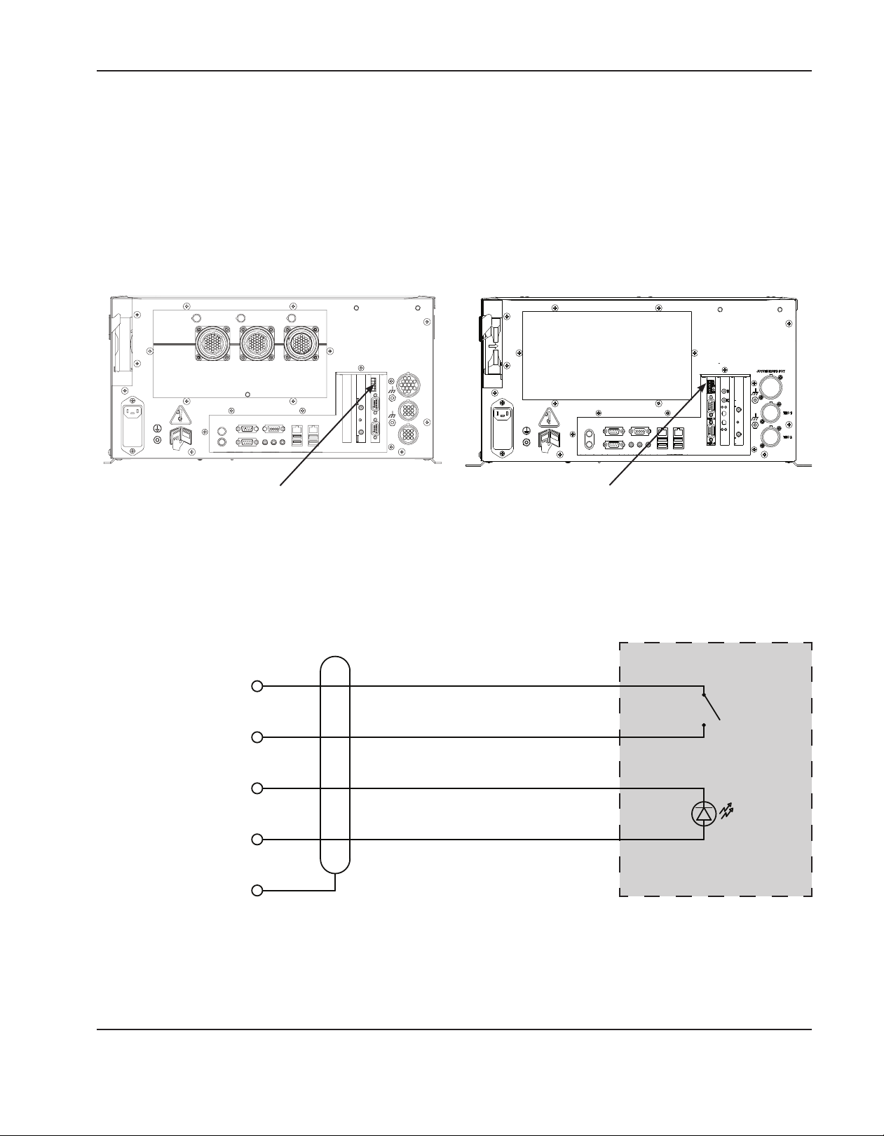
InstallatIon
Remote on/off cable
Hypertherm does not supply a cable that connects to the remote on/off connector on the following boards:
• 141222 for 4-axis HyPath and Picopath
• 141256 for 2-axis Picopath
• 141194/141307 for SERCOSII and SERCOS III
However, Hypertherm provides the cable connector which shipped with the system in the remote on/off port, as shown
in the following illustrations. You can use this connector to terminate a custom-built cable of the appropriate length.
Picopath and HyPath SERCOS II and SERCOS III
Location of the remote on/off connector on the MicroEDGEPro
To build the remote on/off cable, remove the connector from the port and attach purchased wires, a switch, and an LED.
Use the circuit diagram below for details.
1
Remote on/off +
2
Remote on/off -
Customer supplied wiring, switch
and LED
On/Off
3
Common
LED
4
+12 V
5
Shield
Circuit diagram for the remote on/off cable
MicroEDGE Pro Instruction Manual 807290 2-35
Page 84

InstallatIon
Wireless network card
The MicroEDGE Pro supports an optional wireless network card for part downloads, Remote Help, and other network
tasks. The wireless network card is installed in PCI slot 2 on the motherboard. Two antennas extend from the card on
the back of the MicroEDGE Pro. Unfold and adjust the antennas to a 45 degree angle.
When the MicroEDGE Pro is installed within a secondary enclosure, the antennas may be extended up to 3 m (10 ft)
from the wireless network card. When using the 3 m antenna extension cables (223251), only 2.4 GHz frequency can
be used at the router or access point.
Preparing to install the antenna
Follow these guidelines before mounting the antennas on a secondary CNC enclosure:
• The antennas must exit to room air, preferably without metallic obstructions blocking signal transmission (such as
equipment cabinets, circuit breaker panels, transformers, etc).
• Antennas should not be located near the floor.
• Use a plastic protective barrier if necessary to prevent accidental bumping of antenna orientation.
• When mounting the antennas on a secondary CNC enclosure, you will need to drill two holes to accommodate the
threaded, bulkhead-mount antenna connectors. Be sure the connectors make contact with the metal on the enclosure, or use a lock washer to penetrate any coating on the enclosure. Metal-to-metal contact ensures that the
antennas are grounded to the chassis.
• The antenna connections are not waterproof.
Installing the antenna
Before you begin the antenna installation:
• Make sure not to twist or kink the extension cables.
• The extension cables should reside entirely inside the enclosure. Only the antenna itself should be on the outside of
the enclosure.
• Route the cable away from noise generating sources such as power supplies, motor amplifiers, and AC circuits.
• Use a service loop of at least 10 cm (4 in) diameter to coil excess coaxial antenna cable.
2-36 MicroEDGE Pro Instruction Manual 807290
Page 85

InstallatIon
1. After selecting a suitable antenna mounting location, drill two 6.35 mm (.25 in) holes into the secondary CNC
enclosure as shown below (drawing not to scale). Remove any burrs inside and outside.
6.35 mm (.25 in)
diameter
36 mm (1.4 in)
2. Thread each bulkhead-mount antenna base through a hole and secure with a lock washer and nut. Be sure the
antenna base makes contact with unpainted metal on the enclosure to ensure proper grounding.
3. Connect the antennas to the bases and point them skyward.
4. Connect the cables to the coaxial connectors on the wireless network card. Be sure to avoid twisting or kinking
the cables. The entire extension cable should be within the CNC enclosure. Only the antennas are mounted on the
outside of the enclosure.
5. Restore AC power to the CNC.
Checking the wireless network in Windows
The MicroEDGE Pro comes from the factory with the wireless network card drivers installed. To check the wireless
network in Windows:
1. Turn on the MicroEDGE Pro.
2. Choose Setups>Password and enter the Special Setups password.
3. Choose System>Network Tools. The Network Connections dialog opens showing all network connections.
MicroEDGE Pro Instruction Manual 807290 2-37
Page 86
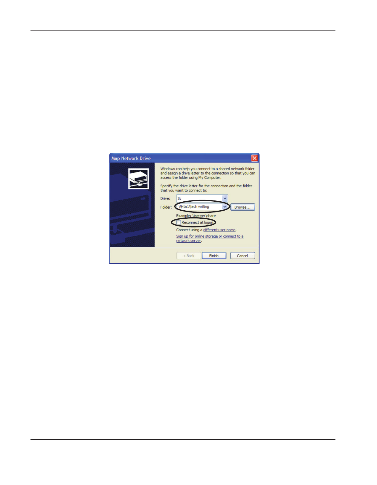
InstallatIon
Mapping a network drive
Phoenix requires a network drive to be defined in Windows. After you define the network drive, you can add it as a folder
in Phoenix.
Before you begin, connect a USB keyboard to the MicroEDGE Pro.
1. Press Alt+F4 to exit the Phoenix software.
2. Choose Start Menu>Windows Explorer>Tools>Map Network Drive.
3. Choose a drive letter, then the folder. Make note of the folder path. When you connect to the folder in Phoenix, you
will need to enter the folder path.
4. Choose Reconnect at Logon.
5. Choose Finish to save the mapped network drive.
2-38 MicroEDGE Pro Instruction Manual 807290
Page 87
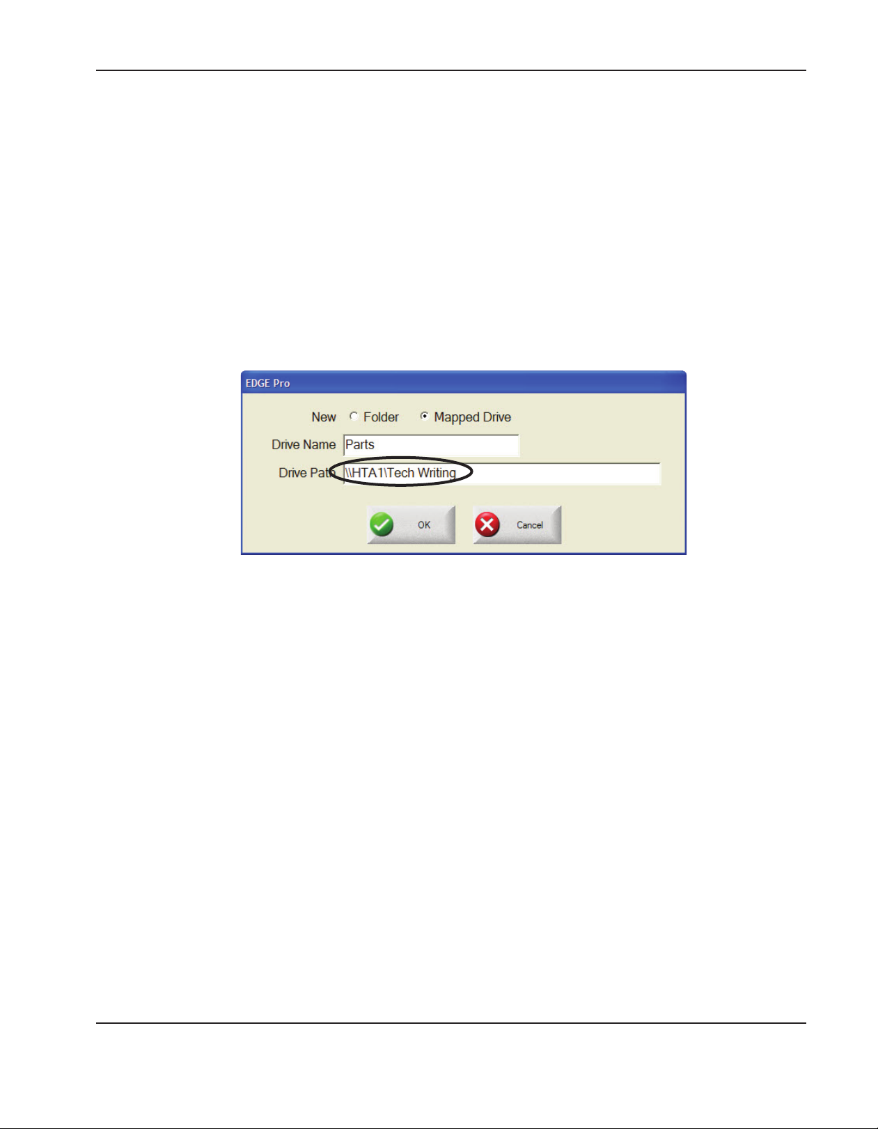
InstallatIon
Adding a folder in Phoenix
Note: The Add Folders feature must be enabled in the Special Setups screen before you can perform these steps.
1. Restart the Phoenix software.
2. From the Main Screen, choose the Files soft key.
3. Double-click the blue message to add a folder.
4. In the dialog, choose Mapped Drive.
5. Enter a Drive Name. This is the name that appears in the Load Files list.
6. Enter the actual path to the drive, not a drive letter. The drive path is formatted \\servername\foldername.
7. Choose OK.
MicroEDGE Pro Instruction Manual 807290 2-39
Page 88

InstallatIon
2-40 MicroEDGE Pro Instruction Manual 807290
Page 89

Section 3
OPERATION
In this section:
Operating the CNC ...................................................................................................................................................................................3-2
Operator console ............................................................................................................................................................................3-2
Touch screen LCD ..........................................................................................................................................................................3-2
LCD display ......................................................................................................................................................................................3-2
Screen navigation ............................................................................................................................................................................3-3
Help ....................................................................................................................................................................................................3-4
View additional manuals ................................................................................................................................................................3-4
Show bookmarks .............................................................................................................................................................................3-5
Automated operations...............................................................................................................................................................................3-5
Align Wizard .....................................................................................................................................................................................3-5
CutPro Wizard .................................................................................................................................................................................3-6
Using Phoenix without a touch screen ..................................................................................................................................................3-6
PC keyboard .....................................................................................................................................................................................3-6
Updating Phoenix software ......................................................................................................................................................................3-7
Updating the software ....................................................................................................................................................................3-7
Updating the Help ...........................................................................................................................................................................3-7
Updating the cut charts .................................................................................................................................................................3-8
MicroEDGE Pro Instruction Manual 807290 3-1
Page 90

OperatiOn
Operating the CNC
Phoenix software runs on the Hypertherm computer numerical controls (CNCs) including the EDGE® Pro and
MicroEDGE® Pro. Phoenix supports either a touch screen or LCD display with a USB-connected keyboard and mouse
for entering information and navigating the software. For more information, see the Phoenix Software Operator’s Manual.
For more information about the components of your cutting system that are supplied by your table manufacturer, refer to
the manuals supplied by the manufacturer
Operator console
An optional operator console provided by an OEM or a system integrator powers up the CNC and controls machine
motion such as station selection, raising or lowering the cutting tool, and positioning the cutting tool before starting a
part program.
Touch screen LCD
The Phoenix software is designed for touch screens with 1024 x 768 resolution and a 4:3 aspect ratio. When your CNC
is equipped with a touch screen, you can enter data into the software by touching the window controls and fields. Any
field that requires data input automatically displays an onscreen keypad when you touch it.
LCD display
The MicroEDGE Pro can support an LCD display and requires 1024 x 768 resolution with a 4:3 aspect ratio.
3-2 MicroEDGE Pro Instruction Manual 807290
Page 91
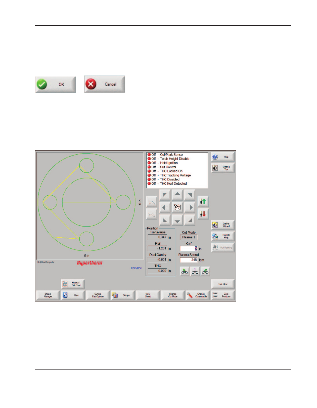
OperatiOn
Screen navigation
The keys located at the bottom of the screen in the software are called soft keys. The soft keys correspond to function
keys on a PC keyboard. OK and Cancel soft keys let you save or cancel changes that you make in a screen.
Refer to the Phoenix Software Operator’s Manual for more details.
Note: The features shown on each screen vary depending on the user level (Beginner, Intermediate, or Advanced) and
the features enabled on the Special Setups and Station Configuration screens. This manual assumes the CNC
is in Advanced Mode and shows all features with an example machine configuration.
Phoenix Main screen
MicroEDGE Pro Instruction Manual 807290 3-3
Page 92

OperatiOn
Help
Choose the Help soft key to display information about each screen.
Choose the OK soft key to exit the Help screen and return to the control screen.
The Show Bookmarks soft key opens the navigation pane. On a keyboard, press Ctrl+F to use full text search.
View additional manuals
The Help screen may also display buttons for other types of information, for example:
• Manuals for the Hypertherm equipment installed with your CNC, such as plasma systems or torch height controls.
• Manuals for equipment provided by your table manufacturer.
Choose any of these buttons to view this additional information.
3-4 MicroEDGE Pro Instruction Manual 807290
Page 93

OperatiOn
Show bookmarks
Choose the Show Bookmarks soft key on the Help screen to view the list of Help topics. Click on a topic in the list to
view it.
Note: If you are operating the MicroEDGE Pro with a keyboard, use the Page Up/Page Down keys to scroll through
the document on screen.
Automated operations
The Phoenix software includes two wizards that automate plate alignment and part cutting operations.
Align Wizard
The Align Wizard automates several tasks including aligning a nest on a plate, adjusting for a skewed plate, and
positioning the torch at the program start location.
To start the Align Wizard, choose Shape Library on the Main screen, then choose Shape Wizard, Shape Options, Align.
The Align Wizard may launch automatically. If not, choose the Align Wizard soft key.
For more information, see Align Wizard in the Arranging Parts chapter of the Phoenix Software Operator’s Manual.
MicroEDGE Pro Instruction Manual 807290 3-5
Page 94

OperatiOn
CutPro Wizard
The CutPro Wizard automates common cutting tasks including loading a part or nest, selecting the cutting process,
aligning the part or nest on the plate, and starting the program.
The CutPro Wizard may launch automatically when you start the CNC. If not, choose the CutPro Wizard soft key on the
Main screen to start the wizard. For more information on the CutPro wizard see the Cutting Parts chapter.
Using Phoenix without a touch screen
Phoenix software supports using a built-in keypad or a USB, PC keyboard to perform functions and data entry in the
Phoenix software.
PC keyboard
Hypertherm CNCs can support a USB, PC keyboard. You can use a keyboard to perform functions and data entry in the
Phoenix software.
A label (210047) is included with the MicroEDGE Pro to modify a PC keyboard to use with Phoenix software, as shown
in the following illustration.
3-6 MicroEDGE Pro Instruction Manual 807290
Page 95

OperatiOn
Updating Phoenix software
Hypertherm provides regular updates to the Phoenix software. You can download the most current software from the
website www.hypertherm.com. Choose Products > Controls for Automation > Software to open the Phoenix Software
Update Downloads page. On this page you can download:
• Phoenix software update (update.exe)
• Phoenix Help file (Help.exe)
• Cut charts (CutChart.exe)
Follow the instructions on the web page to download the updates in your language.
Before you update the Phoenix software, follow these guidelines:
• Back up your system files: On the Main screen, choose Files > Save to Disk > Save System Files to Disk. See the
section Saving System Files in Chapter 11 Diagnostics and Troubleshooting for more information.
• Copy the files that you download from Hypertherm.com to the root folder of a USB memory stick.
• Be prepared to restart the CNC after you have updated the software.
Updating the software
1. At the CNC, plug the memory stick that contains the file update.exe into a USB port.
Note: Verify that update.exe resides in the root folder of the memory stick.
2. On the Main screen, choose Setups > Password. If you are not using a keyboard, double-tap the screen to display
an onscreen keyboard.
3. Enter updatesoftware (all lower case, one word) and choose Enter. The Phoenix software automatically reads the
memory stick and installs the new software.
Updating the Help
1. At the CNC, plug the memory stick that contains the file Help.exe into a USB port.
Note: Verify that Help.exe resides in the root folder of the memory stick.
2. On the Main screen, choose Setups >Password. If you are not using a keyboard, double-tap the screen to display
an onscreen keyboard.
3. Enter updatehelp (all lower case, one word) and choose Enter. The Phoenix software automatically reads the
memory stick and installs the new help file.
MicroEDGE Pro Instruction Manual 807290 3-7
Page 96

OperatiOn
Updating the cut charts
Hypertherm provides cut charts in two different file types: .fac and .usr. The .fac files are the factory-default cut charts.
These cut charts cannot be changed. The .usr cut charts contain any changes you have made to a cut chart and saved
with the Save Process soft key.
The cut chart update file (CutChart.exe) contains both .fac and .usr cut chart files. The update automatically overwrites
all of .usr cut charts. Before installing the update, back up your modified cut charts.
Hypertherm recommends saving modified cut charts as custom cut charts. When you create a custom cut chart,
Phoenix creates a .usr file with a unique name. This prevents the custom cut charts from being overwritten by the .usr
files in CutChart.exe. See the Phoenix Software Operator’s Manual for instructions.
To back up modified cut charts:
1. At the CNC, plug a memory stick into a USB port.
2. On the Main screen, choose one of the cut chart soft keys, such as Plasma 1 Cut Chart.
3. Choose the Save Cut Charts soft key. Phoenix copies all the cut charts associated with the Plasma 1 Torch Type
onto the memory stick.
To update the cut charts:
1. At the CNC, plug the memory stick that contains the file CutChart.exe into a USB port.
Note: Verify that CutChart.exe resides in the root folder of the memory stick.
2. On the Main screen, choose Process, and choose one of the cut chart soft keys such as Plasma 1 Cut Chart.
3. Choose the Load Cut Charts soft key, then choose Yes when prompted to load cut charts from the memory stick.
Phoenix extracts the cut charts and copies them to the hard drive.
4. If you have modified cut charts to copy back onto the hard drive, you will need to exit Phoenix and use Windows®
Explorer to copy your .usr files back onto the hard drive. The cut chart folder is c:\Phoenix\CutCharts.
3-8 MicroEDGE Pro Instruction Manual 807290
Page 97

Section 4
MAINTENANCE AND DIAGNOSTICS
In this section:
Introduction .................................................................................................................................................................................................4-3
Diagnostic tests..........................................................................................................................................................................................4-4
Serial test ..........................................................................................................................................................................................4-6
USB test ............................................................................................................................................................................................4-7
I/O test ...............................................................................................................................................................................................4-8
Axis test ..........................................................................................................................................................................................4-10
THC test ......................................................................................................................................................................................... 4-11
LAN and Hypernet tests .............................................................................................................................................................4-12
Joystick and speedpot test .........................................................................................................................................................4-13
Troubleshooting.......................................................................................................................................................................................4-14
Introduction .................................................................................................................................................................................... 4-14
MicroEDGE Pro troubleshooting tables ..................................................................................................................................4-15
Power up ................................................................................................................................................................................... 4-15
Display ....................................................................................................................................................................................... 4-15
Field power failure ................................................................................................................................................................... 4-15
Input failure ............................................................................................................................................................................... 4-16
Output failure ...........................................................................................................................................................................4-16
Hypernet .................................................................................................................................................................................... 4-17
LAN connection ....................................................................................................................................................................... 4-17
Motion issues ........................................................................................................................................................................... 4-18
THC ............................................................................................................................................................................................ 4-20
Serial communication issues ................................................................................................................................................ 4-21
USB issues ............................................................................................................................................................................... 4-21
Cut quality ................................................................................................................................................................................. 4-21
CNC temperature ...................................................................................................................................................................4-22
CNC is slow ............................................................................................................................................................................. 4-22
Wireless troubleshooting ...................................................................................................................................................................... 4-23
MicroEDGE Pro Instruction Manual 807290 4-1
Page 98

Maintenance and diagnostics
Component locations and information ............................................................................................................................................... 4-24
HyPath 24 I/O board (141070) ................................................................................................................................................ 4-25
Motherboard (141110) ............................................................................................................................................................... 4-27
SERCOS II master board (141116) ........................................................................................................................................4-28
SERCOS III master board (141310) .......................................................................................................................................4-29
Picopath 4-axis servo board (141122) ................................................................................................................................... 4-30
Analog board (141125) .............................................................................................................................................................. 4-34
Power distribution board (141153) ......................................................................................................................................... 4-36
SERCOS II and SERCOS III serial isolation and utility board (141194/141307) ....................................................... 4-38
HyPath 4-axis servo board (141197) ...................................................................................................................................... 4-40
CPC analog breakout board (141210) ..................................................................................................................................4-42
HyPath and Picopath 4-axis MCC, utility, and serial isolation board (141222) ............................................................ 4-44
Picopath 2-axis servo board (141254) ................................................................................................................................... 4-47
Picopath 2-axis MCC, utility, and serial isolation board (141256) ...................................................................................4-50
4-2 MicroEDGE Pro Instruction Manual 807290
Page 99

Maintenance and diagnostics
DANGER
ELECTRIC SHOCK CAN KILL
Disconnect electrical power before performing any maintenance.
See the Safety section in this manual for more safety precautions.
Introduction
Hypertherm assumes that the service personnel who perform troubleshooting testing are high-level
electronic service technicians who have worked with high-voltage electro-mechanical systems. Knowledge
of final isolation troubleshooting techniques is also assumed.
In addition to being technically qualified, maintenance personnel must perform all testing with safety in mind. For more
information, refer to the Safety section for operating precautions and warning formats.
MicroEDGE Pro Instruction Manual 807290 4-3
Page 100

Maintenance and diagnostics
Diagnostic tests
Note: Test kits are required to perform the following diagnostic tests.
Machine interface tests
If you are using a MicroEDGE Pro CNC, you can perform diagnostic tests with the following connectors and Phoenix
software to test the interface ports on the CNC (228831):
• Serial interface RS-232 on the motherboard
• Serial interface RS-422 on the serial isolation board
• Ethernet and Hypernet
• USB
Note: This is the only kit needed for SERCOS II and SERCOS III systems and it is included in the HyPath and
Picopath kits.
The HyPath version of the MicroEDGE Pro CNC offers the following, additional testers (228832):
• I/O (2)
• Axes
• THC
• Joystick and speedpot
The Picopath version of the MicroEDGE Pro CNC offers the following, additional testers (228833):
• I/O (2)
• Axes
• THC
• Joystick and speedpot
Machine interface test screen
4-4 MicroEDGE Pro Instruction Manual 807290
 Loading...