


Plasma Arc
Cutting System
Instruction Manual
801310 – Revision 4
(200/220/240V, 1-Ph,
50/60 Hz)
MAX20
®
EN50199
EN60974-1

MAX20
(200/220/240 Volt, 1-Ph, 50/60 Hz)
Instruction Manual
(P/N 801310)
Revision 4 – November 2001
© Copyright 2001 Hypertherm, Inc.
All Rights Reserved
Hypertherm, and MAX are trademarks of Hypertherm, Inc.
and may be registered in the United States and/or other countries
Hypertherm, Inc.
Hanover, NH USA
www.hypertherm.com

Hypertherm, Inc.
Etna Road, P.O. Box 5010
Hanover, NH 03755 USA
603-643-3441 Tel (Main Office)
603-643-5352 Fax (All Departments)
800-643-9878 Tel (Technical Service)
800-737-2978 Tel (Customer Service)
Hypertherm Automation, LLC
5 Technology Drive
West Lebanon, NH 03755 USA
603-298-7970 Tel
603-298-7977 Fax
Hypertherm Plasmatechnik, GmbH
Technologiepark Hanau
Rodenbacher Chaussee 6
63457 Hanau-Wolfgang, Deutschland
49 6181 58 2100 Tel
49 6181 58 2134 Fax
49 6181 58 2123 (Technical Service)
Hypertherm (S) Pte Ltd
No. 19 Kaki Bukit Road 2
K.B. Warehouse Complex
Singapore 417847, Republic of Singapore
65 6 841 2489 Tel
65 6 841 2490 Fax
65 6 841 2489 (Technical Service)
Japan
1952-14 Yata-Natsumegi
Mishima City, Shizuoka Pref.
411-0801 Japan
81 0 559 75 7387 Tel
81 0 559 75 7376 Fax
Hypertherm UK, Ltd
9 Berkeley Court, Manor Park
Runcorn, Cheshire, England WA7 1TQ
44 1928 579 074 Tel
44 1928 579 604 Fax
France
15 Impasse des Rosiers
95610 Eragny, France
00 800 3324 9737 Tel
00 800 4973 7329 Fax
Hypertherm S.r.l.
Via Torino 2
20123 Milano, Italia
39 02 725 46 312 Tel
39 02 725 46 400 Fax
39 02 725 46 314 (Technical Service)
Hypertherm Europe B.V.
Vaartveld 9
4704 SE Roosendaal, Nederland
31 165 596908 Tel
31 165 596901 Fax
Technical Service:
00 800 49 73 7843 – toll-free in Europe
31 165 596900 Tel
Hypertherm Brasil Ltda.
Rua Visconde de Santa Isabel, 20 – Sala 611
Vila Isabel, RJ
Brasil CEP 20560-120
55 21 2278 6162 Tel
55 21 2578 0947 Fax
3/27/03

ELECTROMAGNETIC COMPATIBILITY (EMC)
EMC INTRODUCTION
Hypertherm's CE-marked equipment is built
in compliance with standard EN50199. The
equipment should be installed and used in
accordance with the information below to
achieve electromagnetic compatibility.
The limits required by EN50199 may not be
adequate to completely eliminate interference when the affected equipment is in
close proximity or has a high degree of
sensitivity. In such cases it may be necessary to use other measures to further
reduce interference.
This plasma equipment is designed for use
only in an industrial environment.
INSTALLATION AND USE
The user is responsible for installing and
using the plasma equipment according to
the manufacturer's instructions. If electromagnetic disturbances are detected then it
shall be the responsibility of the user to resolve the situation with the technical assistance of the manufacturer. In some cases
this remedial action may be as simple as
earthing the cutting circuit, see Earthing of
Workpiece. In other cases it could involve
constructing an electromagnetic screen
enclosing the power source and the work
complete with associated input filters. In all
cases electromagnetic disturbances must
be reduced to the point where they are no
longer troublesome.
ASSESSMENT OF AREA
Before installing the equipment the user
shall make an assessment of potential electromagnetic problems in the surrounding
area. The following shall be taken into
account:
a. Other supply cables, control cables,
signalling and telephone cables; above,
below and adjacent to the cutting equipment.
b. Radio and television transmitters and
receivers.
c. Computer and other control equipment.
d. Safety critical equipment, for example
guarding of industrial equipment.
e. Health of the people around, for
example the use of pacemakers and hearing aids.
f. Equipment used for calibration or measurement.
g. Immunity of other equipment in the environment. User shall ensure that other
equipment being used in the environment is
compatible. This may require additional
protection measures.
h. Time of day that cutting or other activities
are to be carried out.
Earthing of Workpiece
Where the workpiece is not bonded to earth
for electrical safety, nor connected to earth
because of its size and position, for example,
ship's hull or building steelwork, a connection
bonding the workpiece to earth may reduce
emissions in some, but not all instances.
Care should be taken to prevent the earthing
of the workpiece increasing the risk of injury
to users, or damage to other electrical equipment. Where necessary, the connection of
the workpiece to earth should be made by a
direct connection to the workpiece, but in
some countries where direct connection is
not permitted, the bonding should be
achieved by suitable capacitances selected
according to national regulations.
Note. The cutting circuit may or may not be
earthed for safety reasons. Changing the
earthing arrangements should only be authorized by a person who is competent to
assess whether the changes will increase
the risk of injury, for example, by allowing
parallel cutting current return paths which
may damage the earth circuits of other
equipment. Further guidance is given in IEC
TC26 (sec)94 and IEC TC26/108A/CD Arc
Welding Equipment Installation and Use.
Screening and Shielding
Selective screening and shielding of other
cables and equipment in the surrounding
area may alleviate problems of interference.
Screening of the entire plasma cutting
installation may be considered for special
applications
The size of the surrounding area to be
considered will depend on the structure of
the building and other activities that are taking place. The surrounding area may extend
beyond the boundaries of the premises.
METHODS OF REDUCING EMISSIONS
Mains Supply
Cutting equipment must be connected to the
mains supply according to the manufacturer's recommendations. If interference
occurs, it may be necessary to take
additional precautions such as filtering of
the mains supply. Consideration should be
given to shielding the supply cable of permanently installed cutting equipment, in
metallic conduit or equivalent. Shielding
should be electrically continuous throughout
its length. The shielding should be connected to the cutting mains supply so that good
electrical contact is maintained between the
conduit and the cutting power source
enclosure
Maintenance of Cutting Equipment
The cutting equipment must be routinely
maintained according to the manufacturer's
recommendations. All access and service
doors and covers should be closed and
properly fastened when the cutting
equipment is in operation. The cutting
equipment should not be modified in any
way except for those changes and adjustments covered in the manufacturer's
instructions. In particular, the spark gaps of
arc striking and stabilizing devices should
be adjusted and maintained according to
the manufacturer's recommendations.
Cutting Cables
The cutting cables should be kept as short
as possible and should be positioned close
together, running at or close to the floor
level.
Equipotential Bonding
Bonding of all metallic components in the
cutting installation and adjacent to it should
be considered. However, metallic components bonded to the workpiece will increase
the risk that the operator could receive a
shock by touching these metallic
components and the electrode at the same
time. The operator should be insulated from
all such bonded metallic components.
Hypertherm Plasma Systems i

WARRANTY
ii Hypertherm Plasma Systems
9-01
WARNING
Genuine Hypertherm parts are the factory-recommended
replacement parts for your Hypertherm system. Any damage
caused by the use of other than genuine Hypertherm parts may
not be covered by the Hypertherm warranty.
WARNING
You are responsible for the safe use of the Product.
Hypertherm does not and cannot make any guarantee or
warranty regarding the safe use of the Product in your
environment.
GENERAL
Hypertherm, Inc. warrants that its Products shall be free from
defects in materials and workmanship, if Hypertherm is notified
of a defect (i) with respect to the power supply within a period
of two (2) years from the date of its delivery to you, with the
exception of G3 Series power supplies, which shall be within a
period of three (3) years from the date of delivery to you, and
(ii) with respect to the torch and leads within a period of one (1)
year from its date of delivery to you. This warranty shall not
apply to any Product which has been incorrectly installed,
modified, or otherwise damaged. Hypertherm, at its sole
option, shall repair, replace, or adjust, free of charge, any
defective Products covered by this warranty which shall be
returned with Hypertherm’s prior authorization (which shall not
be unreasonably withheld), properly packed, to Hypertherm’s
place of business in Hanover, New Hampshire, or to an
authorized Hypertherm repair facility, all costs, insurance and
freight prepaid. Hypertherm shall not be liable for any repairs,
replacement, or adjustments of Products covered by this
warranty, except those made pursuant to this paragraph or with
Hypertherm’s prior written consent. The warranty above is
exclusive and is in lieu of all other warranties, express,
implied, statutory, or otherwise with respect to the
Products or as to the results which may be obtained
therefrom, and all implied warranties or conditions of
quality or of merchantability or fitness for a particular
purpose or against infringement. The foregoing shall
constitute the sole and exclusive remedy for any breach
by Hypertherm of its warranty. Distributors/OEMs may offer
different or additional warranties, but Distributors/OEMs are
not authorized to give any additional warranty protection to you
or make any representation to you purporting to be binding
upon Hypertherm.
PATENT INDEMNITY
Except only in cases of products not manufactured by
Hypertherm or manufactured by a person other than
Hypertherm not in strict conformity with Hypertherm’s
specifications and in cases of designs, processes, formulae, or
combinations not developed or purported to be developed by
Hypertherm, Hypertherm will defend or settle, at its own
expense, any suit or proceeding brought against you alleging
that the use of the Hypertherm product, alone and not in
combination with any other product not supplied by
Hypertherm, infringes any patent of any third party. You shall
notify Hypertherm promptly upon learning of any action or
threatened action in connection with any such alleged
infringement, and Hypertherm’s obligation to indemnify shall be
conditioned upon Hypertherm’s sole control of, and the
indemnified party’s cooperation and assistance in, the defense
of the claim.
LIMITATION OF LIABILITY
In no event shall Hypertherm be liable to any person or
entity for any incidental, consequential, indirect, or
punitive damages (including but not limited to lost profits)
regardless of whether such liability is based on breach of
contract, tort, strict liability, breach of warranties, failure of
essential purpose or otherwise and even if advised of the
possibility of such damages.
LIABILITY CAP
In no event shall Hypertherm’s liability, whether such
liability is based on breach of contract, tort, strict liability,
breach of warranties, failure of essential purpose or
otherwise, for any claim action suit or proceeding arising
out of or relating to the use of the Products exceed in the
aggregate the amount paid for the Products that gave rise
to such claim.
INSURANCE
At all times you will have and maintain insurance in such
quantities and types, and with coverage sufficient and
appropriate to defend and to hold Hypertherm harmless in
the event of any cause of action arising from the use of the
Products.
NATIONAL AND LOCAL CODES
National and Local codes governing plumbing and electrical
installation shall take precedent over any instructions
contained in this manual. In no event shall Hypertherm be
liable for injury to persons or property damage by reason of any
code violation or poor work practices.
TRANSFER OF RIGHTS
You may transfer any remaining rights you may have
hereunder only in connection with the sale of all or substantially
all of your assets or capital stock to a successor in interest who
agrees to be bound by all of the terms and conditions of this
Warranty.

MAX20 Instruction Manual iii
4
Electromagnetic Compatibility (EMC).......................................................................................................................i
Warranty .....................................................................................................................................................................ii
Section 1 SAFETY..................................................................................................................................................1-1
Recognize Safety Information...................................................................................................................................1-2
Follow Safety Instructions.........................................................................................................................................1-2
Cutting Can Cause Fire or Explosion .......................................................................................................................1-2
Electric Shock Can Kill..............................................................................................................................................1-3
Cutting Can Produce Toxic Fumes...........................................................................................................................1-3
A Plasma Arc Can Cause Injury and Burns..............................................................................................................1-4
Arc Rays Can Burn Eyes and Skin ...........................................................................................................................1-4
Grounding Safety......................................................................................................................................................1-4
Compressed Gas Equipment Safety ........................................................................................................................1-5
Gas Cylinders Can Explode If Damaged ..................................................................................................................1-5
Noise Can Damage Hearing.....................................................................................................................................1-5
Pacemaker and Hearing Aid Operation ....................................................................................................................1-5
A Plasma Arc Can Damage Frozen Pipes................................................................................................................1-5
Additional Safety Information....................................................................................................................................1-5
Warning Label...........................................................................................................................................................1-6
Section 1a SÉCURITÉ........................................................................................................................................1a-1
Identifier les consignes de sécurité.........................................................................................................................1a-2
Suivre les instructions de sécurité ..........................................................................................................................1a-2
Le coupage peut provoquer un incendie ou une explosion ....................................................................................1a-2
Les chocs électriques peuvent être fatals...............................................................................................................1a-3
Le coupage peut produire des vapeurs toxiques....................................................................................................1a-3
L'arc plasma peut provoquer des blessures ou des brûlures .................................................................................1a-4
Mise à la masse et à la terre...................................................................................................................................1a-4
Les rayons de l'arc peuvent brûler les yeux et la peau...........................................................................................1a-4
Sécurité des bouteilles de gaz comprimé ...............................................................................................................1a-5
Les bouteilles de gaz comprimé peuvent exploser en cas de dommages .............................................................1a-5
Le bruit peut provoquer des problèmes auditifs......................................................................................................1a-5
Pacemakers et prothéses auditives........................................................................................................................1a-5
Étiquette de sécurité ...............................................................................................................................................1a-6
Section 2 SPECIFICATIONS................................................................................................................................2-1
General .....................................................................................................................................................................2-2
Product Specifications ..............................................................................................................................................2-3
MAX20 CE Power Supply ................................................................................................................................2-3
PAC110 Torch..................................................................................................................................................2-3
IEC Symbols Used....................................................................................................................................................2-4
Section 3 SETUP..................................................................................................................................................3-1
Upon Receipt ............................................................................................................................................................3-2
Primary Connection ..................................................................................................................................................3-2
Line Voltage and Frequency Selection .....................................................................................................................3-5
Grounding .................................................................................................................................................................3-6
Air Supply .................................................................................................................................................................3-6

TABLE OF CONTENTS
iv MAX20 Instruction Manual
4
Section 4 OPERATION ........................................................................................................................................4-1
Front Panel Controls.................................................................................................................................................4-2
Operating Instructions...............................................................................................................................................4-3
Operating Tips ..........................................................................................................................................................4-4
Changing Consumable Parts ...........................................................................................................................4-4
Adjusting Output Power ...................................................................................................................................4-5
Cutting..............................................................................................................................................................4-6
Piercing ............................................................................................................................................................4-7
Common Cutting Faults ...................................................................................................................................4-8
Duty Cycle........................................................................................................................................................4-8
Gas Pressure ...................................................................................................................................................4-9
Torch Heat .......................................................................................................................................................4-9
Claims and Technical Questions ............................................................................................................................4-10
Section 5 MAINTENANCE ...................................................................................................................................5-1
Troubleshooting ........................................................................................................................................................5-2
Problems: Causes and Solutions .....................................................................................................................5-3
System Illustrations ..........................................................................................................................................5-7
Torch Repair .............................................................................................................................................................5-9
Repair Kit & Customer-Supplied Tools ............................................................................................................5-9
Remove the Defective Torch............................................................................................................................5-9
Install the New Torch .......................................................................................................................................5-9
Section 6 PARTS LIST.........................................................................................................................................6-1
PAC110 Torch Assembly and Leads........................................................................................................................6-2
MAX20 CE Power Supply.........................................................................................................................................6-3
System Descriptions ........................................................................................................................................6-3
MAX20 CE Parts .............................................................................................................................................6-3
Section 7 WIRING DIAGRAMS............................................................................................................................7-1
Wiring Diagram .........................................................................................................................................................7-3

Hypertherm Plasma Systems 1-1
Section 1
SAFETY
In this section:
Recognize Safety Information.........................................................................................................................1-2
Follow Safety Instructions ...............................................................................................................................1-2
Cutting Can Cause Fire or Explosion..............................................................................................................1-2
Electric Shock Can Kill....................................................................................................................................1-3
Cutting Can Produce Toxic Fumes..................................................................................................................1-3
A Plasma Arc Can Cause Injury and Burns.....................................................................................................1-4
Arc Rays Can Burn Eyes and Skin .................................................................................................................1-4
Grounding Safety ............................................................................................................................................1-4
Compressed Gas Equipment Safety...............................................................................................................1-5
Gas Cylinders Can Explode If Damaged ........................................................................................................1-5
Noise Can Damage Hearing ...........................................................................................................................1-5
Pacemaker and Hearing Aid Operation...........................................................................................................1-5
A Plasma Arc Can Damage Frozen Pipes ......................................................................................................1-5
Additional Safety Information ..........................................................................................................................1-5
Warning Label.................................................................................................................................................1-6

SAFETY
1-2 Hypertherm Plasma Systems
11-98
SAFETY
RECOGNIZE SAFETY INFORMATION
The symbols shown in this section are used to identify
potential hazards. When you see a safety symbol in this
manual or on your machine, understand the potential
for personal injury, and follow the related instructions to
avoid the hazard.
FOLLOW SAFETY INSTRUCTIONS
Read carefully all safety messages in this manual and
safety labels on your machine.
• Keep the safety labels on your machine in good
condition. Replace missing or damaged labels
immediately.
• Learn how to operate the machine and how to use
the controls properly. Do not let anyone operate it
without instruction.
• Keep your machine in proper working condition.
Unauthorized modifications to the machine may
affect safety and machine service life.
DANGER WARNING CAUTION
A signal word DANGER or WARNING is used with a
safety symbol. DANGER identifies the most serious
hazards.
• DANGER and WARNING safety labels are located
on your machine near specific hazards.
• WARNING safety messages precede related
instructions in this manual that may result in injury
or death if not followed correctly.
• CAUTION safety messages precede related
instructions in this manual that may result in
damage to equipment if not followed correctly.
Fire Prevention
• Be sure the area is safe before doing any cutting.
Keep a fire extinguisher nearby.
• Remove all flammables within 35 feet (10 m) of the
cutting area.
• Quench hot metal or allow it to cool before handling
or before letting it touch combustible materials.
• Never cut containers with potentially flammable
materials inside – they must be emptied and
properly cleaned first.
• Ventilate potentially flammable atmospheres before
cutting.
• When cutting with oxygen as the plasma gas, an
exhaust ventilation system is required.
Explosion Prevention
• Do not use the plasma system if explosive dust or
vapors may be present.
• Do not cut pressurized cylinders, pipes, or any
closed container.
• Do not cut containers that have held combustible
materials.
CUTTING CAN CAUSE FIRE OR EXPLOSION
WARNING
Explosion Hazard
Argon-Hydrogen and Methane
Hydrogen and methane are flammable gases that
present an explosion hazard. Keep flames away from
cylinders and hoses that contain methane or hydrogen
mixtures. Keep flames and sparks away from the torch
when using methane or argon-hydrogen plasma.
WARNING
Hydrogen Detonation with Aluminum Cutting
• When cutting aluminum underwater, or with the
water touching the underside of the aluminum, free
hydrogen gas may collect under the workpiece and
detonate during plasma cutting operations.
• Install an aeration manifold on the floor of the water
table to eliminate the possibility of hydrogen
detonation. Refer to the Appendix section of this
manual for aeration manifold details.

Touching live electrical parts can cause a fatal shock
or severe burn.
• Operating the plasma system completes an
electrical circuit between the torch and the
workpiece. The workpiece and anything touching
the workpiece are part of the electrical circuit.
• Never touch the torch body, workpiece or the water
in a water table when the plasma system is
operating.
Electric Shock Prevention
All Hypertherm plasma systems use high voltage
in the cutting process (200 to 400 VDC are
common). Take the following precautions when
operating this system:
• Wear insulated gloves and boots, and keep your
body and clothing dry.
• Do not stand, sit or lie on – or touch – any wet
surface when using the plasma system.
• Insulate yourself from work and ground using dry
insulating mats or covers big enough to prevent any
physical contact with the work or ground. If you must
work in or near a damp area, use extreme caution.
• Provide a disconnect switch close to the power
supply with properly sized fuses. This switch allows
the operator to turn off the power supply quickly in
an emergency situation.
• When using a water table, be sure that it is correctly
connected to earth ground.
ELECTRIC SHOCK CAN KILL
• Install and ground this equipment according to the
instruction manual and in accordance with national
and local codes.
• Inspect the input power cord frequently for damage
or cracking of the cover. Replace a damaged power
cord immediately. Bare wiring can kill.
• Inspect and replace any worn or damaged torch
leads.
• Do not pick up the workpiece, including the waste
cutoff, while you cut. Leave the workpiece in place
or on the workbench with the work cable attached
during the cutting process.
• Before checking, cleaning or changing torch parts,
disconnect the main power or unplug the power
supply.
• Never bypass or shortcut the safety interlocks.
• Before removing any power supply or system
enclosure cover, disconnect electrical input power.
Wait 5 minutes after disconnecting the main power
to allow capacitors to discharge.
• Never operate the plasma system unless the power
supply covers are in place. Exposed power supply
connections present a severe electrical hazard.
• When making input connections, attach proper
grounding conductor first.
• Each Hypertherm plasma system is designed to be
used only with specific Hypertherm torches. Do not
substitute other torches which could overheat and
present a safety hazard.
Cutting can produce toxic fumes and gases that
deplete oxygen and cause injury or death.
• Keep the cutting area well ventilated or use an
approved air-supplied respirator.
• Do not cut in locations near degreasing, cleaning or
spraying operations. The vapors from certain
chlorinated solvents decompose to form phosgene
gas when exposed to ultraviolet radiation.
• Do not cut metal coated or containing toxic materials, such as zinc (galvanized), lead, cadmium or
CUTTING CAN PRODUCE TOXIC FUMES
beryllium, unless the area is well ventilated and the
operator wears an air-supplied respirator. The
coatings and any metals containing these elements
can produce toxic fumes when cut.
• Never cut containers with potentially toxic materials
inside – they must be emptied and properly cleaned
first.
• This product, when used for welding or cutting,
produces fumes or gases which contain chemicals
known to the State of California to cause birth
defects and, in some cases, cancer.
Hypertherm Plasma Systems 1-3
8-99
SAFETY

SAFETY
1-4 Hypertherm Plasma Systems
4-99
SAFETY
Instant-On Torches
Plasma arc comes on immediately when the torch
switch is activated.
A PLASMAARC CAN CAUSE INJURYAND BURNS
The plasma arc will cut quickly through gloves and
skin.
• Keep away from the torch tip.
• Do not hold metal near the cutting path.
• Never point the torch toward yourself or others.
Eye Protection Plasma arc rays produce intense
visible and invisible (ultraviolet and infrared) rays that
can burn eyes and skin.
• Use eye protection in accordance with applicable
national or local codes.
• Wear eye protection (safety glasses or goggles with
side shields, or a welding helmet) with appropriate
lens shading to protect your eyes from the arc’s
ultraviolet and infrared rays.
Lens Shade
Arc Current AWS (USA) ISO 4850
Up to 100 A No. 8 No. 11
100-200 A No. 10 No. 11-12
200-400 A No. 12 No. 13
Over 400 A No. 14 No. 14
ARC RAYS CAN BURN EYES AND SKIN
Skin Protection Wear protective clothing to protect
against burns caused by ultraviolet light, sparks and
hot metal.
• Gauntlet gloves, safety shoes and hat.
• Flame-retardant clothing to cover all exposed areas.
• Cuffless trousers to prevent entry of sparks and
slag.
• Remove any combustibles, such as a butane lighter
or matches, from your pockets before cutting.
Cutting Area Prepare the cutting area to reduce
reflection and transmission of ultraviolet light:
• Paint walls and other surfaces with dark colors to
reduce reflection.
• Use protective screens or barriers to protect others
from flash and glare.
• Warn others not to watch the arc. Use placards or
signs.
Work Cable Attach the work cable securely to the
workpiece or the work table with good metal-to-metal
contact. Do not connect it to the piece that will fall
away when the cut is complete.
Work Table Connect the work table to an earth
ground, in accordance with appropriate national or
local electrical codes.
GROUNDING SAFETY
Input Power
• Be sure to connect the power cord ground wire to
the ground in the disconnect box.
• If installation of the plasma system involves
connecting the power cord to the power supply, be
sure to connect the power cord ground wire
properly.
• Place the power cord's ground wire on the stud first,
then place any other ground wires on top of the
power cord ground. Fasten the retaining nut tightly.
• Tighten all electrical connections to avoid excessive
heating.

SAFETY
Hypertherm Plasma Systems 1-5
11-98
SAFETY
• Never lubricate cylinder valves or regulators with oil
or grease.
• Use only correct gas cylinders, regulators, hoses
and fittings designed for the specific application.
• Maintain all compressed gas equipment and
associated parts in good condition.
• Label and color-code all gas hoses to identify the
type of gas in each hose. Consult applicable
national or local codes.
GAS CYLINDERS CAN
EXPLODE IF DAMAGED
COMPRESSED GAS EQUIPMENT SAFETY
Gas cylinders contain gas under high pressure. If
damaged, a cylinder can explode.
• Handle and use compressed gas cylinders in
accordance with applicable national or local codes.
• Never use a cylinder that is not upright and secured
in place.
• Keep the protective cap in place over valve except
when the cylinder is in use or connected for use.
• Never allow electrical contact between the plasma
arc and a cylinder.
• Never expose cylinders to excessive heat, sparks,
slag or open flame.
• Never use a hammer, wrench or other tool to open
a stuck cylinder valve.
Prolonged exposure to noise from cutting or gouging
can damage hearing.
• Use approved ear protection when using plasma
system.
• Warn others nearby about the noise hazard.
NOISE CAN DAMAGE HEARING
Pacemaker and hearing aid operation can be affected
by magnetic fields from high currents.
Pacemaker and hearing aid wearers should consult a
doctor before going near any plasma arc cutting and
gouging operations.
To reduce magnetic field hazards:
• Keep both the work cable and the torch lead to one
side, away from your body.
• Route the torch leads as close as possible to the
work cable.
• Do not wrap or drape the torch lead or work cable
around your body.
• Keep as far away from the power supply as
possible.
P ACEMAKER AND HEARING
AID OPERATION
ADDITIONAL SAFETY INFORMATION
1. ANSI Standard Z49.1, Safety in Welding and Cutting, American
Welding Society, 550 LeJeune Road
P.O. Box 351020, Miami, FL 33135
2. ANSI Standard Z49.2, Fire Prevention in the Use of Cutting and
Welding Processes, American National Standards Institute
1430 Broadway, New York, NY 10018
3. ANSI Standard Z87.1, Safe Practices for Occupation and
Educational Eye and Face Protection, American National
Standards Institute, 1430 Broadway, New York, NY 10018
4. AWS F4.1, Recommended Safe Practices for the Preparation for
Welding and Cutting of Containers and Piping That Have Held
Hazardous Substances, American Welding Society
550 LeJeune Road, P.O. Box 351040, Miami, FL 33135
5. AWS F5.2, Recommended Safe Practices for Plasma Arc
Cutting, American Welding Society
550 LeJeune Road, P.O. Box 351040, Miami, FL 33135
6. CGA Pamphlet P-1, Safe Handling of Compressed Gases in
Cylinders, Compressed Gas Association
1235 Jefferson Davis Highway, Arlington, VA 22202
7. CSA Standard W117.2, Code for Safety in Welding and Cutting,
Canadian Standards Association Standard Sales
178 Rexdale Boulevard, Rexdale, Ontario M9W 1R3, Canada
8. NFPA Standard 51B, Cutting and Welding Processes, National
Fire Protection Association
470 Atlantic Avenue, Boston, MA 02210
9. NFPA Standard 70–1978, National Electrical Code, National Fire
Protection Association, 470 Atlantic Avenue, Boston, MA 02210
10. OSHA, Safety and Health Standards, 29FR 1910
U.S. Government Printing Office, Washington, D.C. 20402
A PLASMAARC CAN
DAMAGE FROZEN PIPES
Frozen pipes may be damaged or can burst if you
attempt to thaw them with a plasma torch.

SAFETY
1-6 Hypertherm Plasma Systems
8-99
SAFETY
WARNING LABEL
This warning label is affixed to some power supplies. It is
important that the operator and maintenance technician
understand the intent of these warning symbols as described.
The numbered text corresponds to the numbered boxes on
the label.
1. Cutting sparks can cause explosion or fire.
1.1 Keep flammables away from cutting.
1.2 Keep a fire extinguisher nearby, and have
a watchperson ready to use it.
1.3 Do not cut on any closed containers.
2. The plasma arc can cause injury and
burns.
2.1 Turn off power before disassembling torch.
2.2 Do not hold the material near cutting path.
2.3 Wear complete body protection.
3. Electric shock from torch or wiring can kill.
Protect yourself from electric shock.
3.1 Wear insulating gloves. Do not wear wet or
damaged gloves.
3.2 Insulate yourself from work and ground.
3.3 Disconnect input plug or power before
working on machine.
4. Breathing cutting fumes can be hazardous
to your health.
4.1 Keep your head out of the fumes.
4.2 Use forced ventilation or local exhaust to
remove the fumes.
4.3 Use ventilating fan to remove the fumes.
5. Arc rays can burn eyes and injure skin.
5.1 Wear hat and safety glasses. Use ear
protection and button shirt collar. Use
welding helmet with correct shade of filter.
Wear complete body protection.
6. Become trained and read the instructions
before working on the machine or cutting.
7. Do not remove or paint over (cover)
warning labels.

Hypertherm Systèmes plasma 1a-1
2/12/01
Section 1
SÉCURITÉ
Dans cette section :
Identifier les consignes de sécurité.................................................................................................................1-2
Suivre les instructions de sécurité...................................................................................................................1-2
Danger Avertissement Précaution.................................................................................................................1-2
Le coupage peut provoquer un incendie ou une explosion.............................................................................1-2
Prévention des incendies, Prévention des explosions ...........................................................................1-2
Risque d’explosion argon-hydrogène et méthane..................................................................................1-2
Détonation de l’hydrogène lors du coupage de l’aluminium...................................................................1-2
Les chocs électriques peuvent être fatals.......................................................................................................1-3
Prévention des chocs électriques...........................................................................................................1-3
Le coupage peut produire des vapeurs toxiques ............................................................................................1-3
L’arc plasma peut provoquer des blessures ou des brûlures..........................................................................1-4
Torches à allumage instantané...............................................................................................................1-4
Les rayons de l’arc peuvent brûler les yeux et la peau...................................................................................1-4
Protection des yeux, Protection de la peau, Zone de coupage ............................................................1-4
Mise à la masse et à la terre...........................................................................................................................1-4
Câble de retour, Table de travail, Alimentation .......................................................................................1-4
Sécurité des bouteilles de gaz comprimé .......................................................................................................1-5
Les bouteilles de gaz comprimé peuvent exploser en cas de dommages......................................................1-5
Le bruit peut provoquer des problèmes auditifs..............................................................................................1-5
Pacemakers et prothèses auditives ................................................................................................................1-5
Un arc plasma peut endommager les tuyaux gelés........................................................................................1-5
Étiquette de sécurité .......................................................................................................................................1-6

SÉCURITÉ
1a-2 Hypertherm Systèmes plasma
2/12/01
IDENTIFIER LES CONSIGNES
DE SÉCURITÉ
Les symboles indiqués dans cette section sont utilisés pour
identifier les risques éventuels. Si vous trouvez un symbole
de sécurité, que ce soit dans ce manuel ou sur
l’équipement, soyez conscient des risques de blessures et
suivez les instructions correspondantes afin d’éviter ces
risques.
SUIVRE LES INSTRUCTIONS
DE SÉCURITÉ
Lire attentivement toutes les consignes de sécurité dans le
présent manuel et sur les étiquettes de sécurité se trouvant
sur la machine.
• Les étiquettes de sécurité doivent rester lisibles.
Remplacer immédiatement les étiquettes manquantes ou
abîmées.
• Apprendre à faire fonctionner la machine et à utiliser
correctement les commandes. Ne laisser personne utiliser
la machine sans connaître son fonctionnement.
• Garder la machine en bon état. Des modifications non
autorisées sur la machine peuvent engendrer des
problèmes de sécurité et raccourcir la durée d’utilisation
de l’équipement.
DANGER AVERTISSEMENT PRÉCAUTION
Les signaux DANGER ou AVERTISSEMENT sont utilisés
avec un symbole de sécurité, DANGER correspondant aux
risques les plus sérieux.
• Les étiquettes de sécurité DANGER et AVERTISSEMENT
sont situées sur la machine pour signaler certains
dangers spécifiques.
• Les messages d’AVERTISSEMENT précèdent les
instructions d’utilisation expliquées dans ce manuel et
signalent les risques de blessures ou de mort au cas où
ces instructions ne seraient pas suivies correctement.
• Les messages de PRÉCAUTION précèdent les
instructions d’utilisation contenues dans ce manuel et
signalent que le matériel risque d’être endommagé si les
instructions ne sont pas suivies correctement.
Prévention des incendies
• Avant de commencer, s’assurer que la zone de coupage
ne présente aucun danger. Conserver un extincteur à
proximité.
• Éloigner toute matière inflammable à une distance d’au
moins 10 m du poste de coupage.
• Tremper le métal chaud ou le laisser refroidir avant de
le manipuler ou avant de le mettre en contact avec des
matériaux combustibles.
• Ne jamais couper des récipients pouvant contenir des
matières inflammables avant de les avoir vidés et
nettoyés correctement.
• Aérer toute atmosphère potentiellement inflammable
avant d’utiliser un système plasma.
• Lors de l’utilisation d’oxygène comme gaz plasma, un
système de ventilation par aspiration est nécessaire.
Prévention des explosions
• Ne pas couper en présence de poussière ou de vapeurs.
• Ne pas couper de bouteilles, de tuyaux ou autres
récipients fermés et pressurisés.
• Ne pas couper de récipients contenant des matières
combustibles.
LE COUPAGE PEUT PROVOQUER UN INCENDIE
OU UNE EXPLOSION
AVERTISSEMENT
Risque d’explosion
argon-hydrogène et méthane
L’hydrogène et le méthane sont des gaz inflammables et
potentiellement explosifs. Conserver à l’écart de toute
flamme les bouteilles et tuyaux contenant des mélanges à
base d’hydrogène ou de méthane. Maintenir toute flamme
et étincelle à l’écart de la torche lors de l’utilisation d’un
plasma d’argon-hydrogène ou de méthane.
AVERTISSEMENT
Détonation de l’hydrogène lors du
coupage de l’aluminium
• Lors du coupage de l’aluminium sous l’eau, ou si l’eau
touche la partie inférieure de la pièce d’aluminium, de
l’hydrogène libre peut s’accumuler sous la pièce à couper
et détonner lors du coupage plasma.
• Installer un collecteur d’aération au fond de la table à eau
afin d’éliminer les risques de détonation de l’hydrogène.
Se référer à l’annexe du manuel pour plus de
renseignements sur les collecteurs d’aération.

SÉCURITÉ
Hypertherm Systèmes plasma 1a-3
2/12/01
Toucher une pièce électrique sous tension peut provoquer
un choc électrique fatal ou des brûlures graves.
• La mise en fonctionnement du système plasma ferme un
circuit électrique entre la torche et la pièce à couper. La
pièce à couper et tout autre élément en contact avec cette
pièce font partie du circuit électrique.
• Ne jamais toucher le corps de la torche, la pièce à couper
ou l’eau de la table à eau pendant le fonctionnement du
système plasma.
Prévention des chocs électriques
Tous les systèmes plasma Hypertherm utilisent des hautes
tensions pour le coupage (souvent de 200 à 400 V). On
doit prendre les précautions suivantes quand on utilise le
système plasma :
• Porter des bottes et des gants isolants et garder le corps
et les vêtements au sec.
• Ne pas se tenir, s’asseoir ou se coucher sur une surface
mouillée, ni la toucher quand on utilise le système plasma.
• S’isoler de la surface de travail et du sol en utilisant des
tapis isolants secs ou des couvertures assez grandes
pour éviter tout contact physique avec le travail ou le sol.
S’il s’avère nécessaire de travailler dans ou près d’un
endroit humide, procéder avec une extrême prudence.
• Installer un sectionneur avec fusibles appropriés, à
proximité de la source de courant. Ce dispositif permet à
l’opérateur d’arrêter rapidement la source de courant en
cas d’urgence.
• En cas d’utilisation d’une table à eau, s’assurer que cette
dernière est correctement mise à la terre.
LES CHOCS ÉLECTRIQUES PEUVENT ÊTRE FATALS
• Installer et mettre à la terre l’équipement selon les
instructions du présent manuel et conformément aux
codes électriques locaux et nationaux.
• Inspecter fréquemment le cordon d’alimentation primaire
pour s’assurer qu’il n’est ni endommagé, ni fendu.
Remplacer immédiatement un cordon endommagé.
Un câble dénudé peut tuer.
• Inspecter et remplacer les câbles de la torche qui sont
usés ou endommagés.
• Ne pas saisir la pièce à couper ni les chutes lors du
coupage. Laisser la pièce à couper en place ou sur la
table de travail, le câble de retour connecté lors du
coupage.
• Avant de vérifier, de nettoyer ou de remplacer les pièces
de la torche, couper l’alimentation ou débrancher la prise
de courant.
• Ne jamais contourner ou court-circuiter les verrouillages
de sécurité.
• Avant d’enlever le capot du système ou de la source de
courant, couper l’alimentation électrique. Attendre en
suite
5 minutes pour que les condensateurs se déchargent.
• Ne jamais faire fonctionner le système plasma sans que
les capots de la source de courant ne soient en place.
Les raccords exposés de la source de courant sont
extrêmement dangereux.
• Lors de l’installation des connexions, attacher tout d’abord
la prise de terre appropriée.
• Chaque système plasma Hypertherm est conçu pour être
utilisé uniquement avec des torches Hypertherm
spécifiques. Ne pas utiliser des torches inappropriées qui
pourraient surchauffer et présenter des risques pour la
sécurité.
Le coupage peut produire des vapeurs et des gaz toxiques
qui réduisent le niveau d’oxygène dans l’air et peuvent
provoquer des blessures, voire la mort.
• Conserver le poste de coupage bien aéré ou utiliser un
masque respiratoire homologué.
• Ne pas procéder au coupage près d’endroits où
s’effectuent le dégraissage, le nettoyage ou la vaporisation. Certains solvants chlorés se décomposent sous
l’effet des rayons ultraviolets et forment du phosgène.
• Ne pas couper des métaux peints ou contenant des
matières toxiques comme le zinc (galvanisé), le plomb, le
cadmium ou le béryllium, à moins que la zone de travail
LE COUPAGE PEUT PRODUIRE DES VAPEURS TOXIQUES
soit très bien ventilée et que l’opérateur porte un masque
respiratoire. Les revêtements et métaux contenant ces
matières peuvent produire des vapeurs toxiques lors du
coupage.
• Ne jamais couper de récipients pouvant contenir des
matières inflammables avant de les avoir vidés et
nettoyés correctement.
• Quand on utilise ce produit pour le soudage ou le
coupage, il dégage des fumées et des gaz qui
contiennent des produits chimiques qui, selon l’État de
Californie, provoquent des anomalies congénitales et,
dans certains cas, le cancer.

SÉCURITÉ
1a-4 Hypertherm Systèmes plasma
2/12/01
Torches à allumage instantané
L’arc plasma s’allume immédiatement après que la torche
soit mise en marche.
L’ARC PLASMA PEUT PROVOQUER DES BLESSURES OU DES BRÛLURES
L’arc plasma coupe facilement les gants et la peau.
• Rester éloigné de l’extrémité de la torche.
• Ne pas tenir de métal près de la trajectoire de coupe.
• Ne jamais pointer la torche vers soi ou d’autres
personnes.
Protection des yeux Les rayons de l’arc plasma
produisent de puissants rayons visibles ou invisibles
(ultraviolets et infrarouges) qui peuvent brûler les yeux et la
peau.
• Utiliser des lunettes de sécurité conformément aux codes
locaux ou nationaux en vigueur.
• Porter des lunettes de protection (lunettes ou masque
muni d’écrans latéraux ou encore masque de soudure)
avec des verres teintés appropriés pour protéger les yeux
des rayons ultraviolets et infrarouges de l’arc.
Puissance des verres teintés
Courant de l’arc AWS (É.-U.) ISO 4850
Jusqu’à 100 A No8N
o
11
100-200 A No10 No11-12
200-400 A No12 No13
Plus de 400 A No14 No14
Protection de la peau Porter des vêtements de sécurité
pour se protéger contre les brûlures que peuvent causer les
rayons ultraviolets, les étincelles et le métal brûlant :
LES RAYONS DE L’ARC PEUVENT BRÛLER LES YEUX ET LA PEAU
• Gants à crispin, chaussures et casque de sécurité.
• Vêtements ignifuges couvrant toutes les parties exposées
du corps.
• Pantalon sans revers pour éviter que des étincelles ou
des scories puissent s’y loger.
• Avant le coupage, retirer de ses poches tout objet
combustible comme les briquets au butane ou les
allumettes.
Zone de coupage Préparer la zone de coupage afin de
réduire la réverbération et la transmission de la lumière
ultraviolette :
• Peindre les murs et autres surfaces de couleur sombre
pour réduire la réflexion de la lumière.
• Utiliser des écrans et autres dispositifs de protection afin
de protéger les autres personnes de la lumière et de la
réverbération.
• Prévenir les autres personnes de ne pas regarder l’arc.
Utiliser des affiches ou des panneaux.
Câble de retour Bien fixer le câble de retour (ou de
masse) à la pièce à couper ou à la table de travail de façon
à assurer un bon contact métal-métal. Ne pas fixer le câble
de retour à la partie de la pièce qui doit se détacher.
Table de travail Raccorder la table de travail à la terre,
conformément aux codes de sécurité locaux ou nationaux
appropriés.
MISE À LA MASSE ET À LA TERRE
Alimentation
• S’assurer que le fil de terre du cordon d’alimentation est
connecté à la terre dans le coffret du sectionneur.
• S’il est nécessaire de brancher le cordon d’alimentation à
la source de courant lors de l’installation du système,
s’assurer que le fil de terre est correctement branché.
• Placer tout d’abord le fil de terre du cordon d’alimentation
sur le plot de mise à la terre puis placer les autres fils de
terre par-dessus. Bien serrer l’écrou de retenue.
• S’assurer que toutes les connexions sont bien serrées
pour éviter la surchauffe.

SÉCURITÉ
Hypertherm Systèmes plasma 1a-5
2/12/01
• Ne jamais lubrifier les robinets des bouteilles ou les
régulateurs avec de l’huile ou de la graisse.
• Utiliser uniquement les bouteilles, régulateurs, tuyaux et
accessoires appropriés et conçus pour chaque application
spécifique.
• Entretenir l’équipement et les pièces d’équipement à gaz
comprimé afin de les garder en bon état.
• Étiqueter et coder avec des couleurs tous les tuyaux de
gaz afin d’identifier le type de gaz contenu dans chaque
tuyau. Se référer aux codes locaux ou nationaux en
vigueur.
LES BOUTEILLES DE GAZ
COMPRIMÉ PEUVENT EXPLOSER
EN CAS DE DOMMAGES
SÉCURITÉ DES BOUTEILLES DE
GAZ COMPRIMÉ
Les bouteilles de gaz contiennent du gaz à haute pression.
Si une bouteille est endommagée, elle peut exploser.
• Manipuler et utiliser les bouteilles de gaz comprimé
conformément aux codes locaux ou nationaux.
• Ne jamais utiliser une bouteille qui n’est pas placée à la
verticale et bien assujettie.
• Le capuchon de protection doit être placé sur le robinet
sauf si la bouteille est en cours d’utilisation ou connectée
pour utilisation.
• Éviter à tout prix le contact électrique entre l’arc plasma et
une bouteille.
• Ne jamais exposer des bouteilles à une chaleur
excessive, aux étincelles, aux scories ou aux flammes
nues.
• Ne jamais utiliser des marteaux, des clés ou d’autres
outils pour débloquer le robinet des bouteilles.
Une exposition prolongée au bruit du coupage ou du
gougeage peut provoquer des problèmes auditifs.
• Utiliser un casque de protection homologué lors de
l’utilisation du système plasma.
• Prévenir les personnes aux alentours des risques
encourus en cas d’exposition au bruit.
LE BRUIT PEUT PROVOQUER DES
PROBLÈMES AUDITIFS
Les champs magnétiques produits par les courants à haute
tension peuvent affecter le fonctionnement des prothèses
auditives et des pacemakers. Les personnes portant ce
type d’appareil doivent consulter un médecin avant de
s’approcher d’un lieu où s’effectue le coupage ou le
gougeage plasma.
Pour réduire les risques associés aux champs magnétiques :
• Garder loin de soi et du même côté du corps le câble de
retour et le faisceau de la torche.
• Faire passer le faisceau de la torche le plus près possible
du câble de retour.
• Ne pas s’enrouler le faisceau de la torche ou le câble de
retour autour du corps.
• Se tenir le plus loin possible de la source de courant.
PACEMAKERS ET
PROTHÈSES AUDITIVES
Les tuyaux gelés peuvent être endommagés ou éclater
si l'on essaie de les dégeler avec une torche plasma.
UN ARC PLASMA
PEUT ENDOMMAGER
LES TUYAUX GELÉS

SÉCURITÉ
1a-6 Hypertherm Systèmes plasma
2/12/01
Étiquette de sécurité
Cette étiquette est affichée sur la source de courant. Il est important
que l’utilisateur et le technicien de maintenance comprennent la
signification des symboles de sécurité. Les numéros de la liste
correspondent aux numéros des images.
1. Les étincelles produites par le coupage
peuvent provoquer une explosion ou un
incendie.
1.1 Pendant le coupage, éloigner toute matière
inflammable.
1.2 Conserver un extincteur à proximité et
s’assurer qu’une personne soit prête à
l’utiliser.
1.3 Ne jamais couper de récipients fermés.
2. L’arc plasma peut provoquer des blessures
et des brûlures.
2.1 Couper l’alimentation avant de démonter la
torche.
2.2 Ne pas tenir la surface à couper près de la
trajectoire de coupe.
2.3 Porter des vêtements de protection
couvrant tout le corps.
3. Un choc électrique causé par la torche ou
les câbles peut être fatal. Se protéger
contre les risques de chocs électriques.
3.1 Porter des gants isolants. Ne pas porter de
gants mouillés ou abîmés.
3.2 S’isoler de la surface de travail et du sol.
3.3 Débrancher la prise ou la source de
courant avant de manipuler l’équipement.
4. L’inhalation des vapeurs produites par le
coupage peut être dangereuse pour la
santé.
4.1 Garder le visage à l’écart des vapeurs.
4.2 Utiliser un système de ventilation par
aspiration ou d’échappement localisé pour
dissiper les vapeurs.
4.3 Utiliser un ventilateur pour dissiper les
vapeurs.
5. Les rayons de l’arc peuvent brûler les yeux
et provoquer des lésions de la peau.
5.1 Porter un casque et des lunettes de
sécurité. Se protéger les oreilles et porter
une chemise dont le col peut être
déboutonné. Porter un casque de soudure
dont la protection filtrante est suffisante.
Porter des vêtements protecteurs couvrant
la totalité du corps.
6. Se former à la technique du coupage et lire
les instructions avant de manipuler
l’équipement ou de procéder au coupage.
7. Ne pas retirer ou peindre (recouvrir) les
étiquettes de sécurité.

MAX20 Instruction Manual 2-1
4
Section 2
SPECIFICATIONS
In this section:
General .....................................................................................................................................................................2-2
Product Specifications ..............................................................................................................................................2-3
MAX20 CE Power Supply ................................................................................................................................2-3
PAC110 Torch...................................................................................................................................................2-3
IEC Symbols Used....................................................................................................................................................2-4

2-2 MAX20 Instruction Manual
4
SPECIFICATIONS
General
• Hypertherm’s MAX20 CE air plasma cutting system is designed for hand cutting of most metals up to 6 mm
(1/4 inch) in thickness.
• The MAX20 provides continuously variable current output from 10 to 20 amps to provide excellent cutting
performance on all thicknesses within its range.
• The MAX20 power supply uses 200/220/240-volt, single-phase, 50/60 hertz power and incorporates advanced
transistor technology. It offers the following benefits:
– It weighs only 20 kg (44 pounds), offering maximum portability.
– The pilot arc ignition pierces coated, painted or rusted metals.
– The solid-state design allows a steady cutting arc between the torch and the workpiece.
– The transistorized design performs best while lightly dragging the torch nozzle on the workpiece. This makes
the torch extremely easy to use.
– The continuous pilot arc makes it easy to cut grate material or other perforated metals. The pilot arc transfers
to the workpiece when the torch is within 3 mm (1/8 inch) of the cutting surface.
– The nearly ripple-free output provides a smooth cutting arc, ensuring high-quality cuts across a wide variety of
materials and thicknesses.
• The MAX20 uses compressed air as the plasma gas. A cylinder of compressed air or an air compressor may be
used. The air supply must be free of moisture, oil or other contaminants. An air pressure regulator and air filter
are provided. The air pressure regulator is preset to deliver the correct air flow and pressure.
• The variable amperage output (OUTPUT POWER) potentiometer mounted on the front panel adjusts the cutting
current of the torch and varies the AC line draw of the system to conform with the fuse size at the primary power
line.

MAX20 Instruction Manual 2-3
4
SPECIFICATIONS
Product Specifications
MAX20 CE Power Supply
The MAX20 CE (070049) is a constant current chopper power supply providing continuously variable
amperage from 10 amps to 20 amps. It conforms to the following specifications:
Rated OCV (U
0
) ...................................................240 VDC at rated input voltage
Output Current (I2)................................................10 amps minimum to 20 amps maximum
Output Voltage (U2) .............................................84 VDC @ 10 amps; 88 VDC @ 20 amps
Duty Cycle Rating (X) ..........................................25% duty cycle (20 amps, 88 VDC);
100% duty cycle 10 amps.)
Input Voltage (V1).................................................200-220-240V, 1PH, 50/60 Hz, jumper selectable
Input Current (I1) ..................................................13.0 amps @ 1.8 kw out (200-volt input)
11.8 amps @ 1.8 kw out (220-volt input)
10.8 amps @ 1.8 kw out (240-volt input)
Dimensions
Width ....................................................................200 mm (8 inches)
Height...................................................................298 mm (11.75 inches)
Length ..................................................................432 mm (17 inches)
Weight ..................................................................20 kg (44 U.S. pounds)
Gas Supply
Type .....................................................................Air
Quality ..................................................................Clean, Dry, Oil-Free
Air Flow ................................................................127 liters/minute (4.5 scfm)
Air Pressure Setting .............................................4.1 bar (60 psi) for 4.5 meter (15-foot) lead set
4.5 bar (65 psi) for 7.5 meter (25-foot) lead set
Air Requirements .................................................4.8-8.6 bar (70-125 psi)
PAC110 Torch
The PAC110 torch conforms to the following specifications:
Maximum cutting thickness range........................ Up to 6 mm (1/4 inch)
Maximum current at 50% duty cycle ....................20 Amps
Maximum current at 100% duty cycle ..................10 Amps
Gas Flow ..............................................................127 liters/minute (4.5 scfm)
Weight ..................................................................1.4 kg (3 U.S. pounds)

2-4 MAX20 Instruction Manual
4
SPECIFICATIONS
IEC Symbols Used
Direct Current (DC).
Alternating current (AC).
Plasma cutting torch.
AC input power connection.
The terminal for the external protective (earthed) conductor.
A chopper-based power source.
Anode (+) work clamp.
Temperature switch.
Pressure switch.
Plasma torch in the TEST position (cooling and cutting gas exiting nozzle).
The power is on.
The power is off.
Volt/amp curve.

MAX20 Instruction Manual 3-1
4
Section 3
SETUP
In this section:
Upon Receipt ............................................................................................................................................................3-2
Primary Connection ..................................................................................................................................................3-2
Line Voltage and Frequency Selection .....................................................................................................................3-5
Grounding .................................................................................................................................................................3-6
Air Supply .................................................................................................................................................................3-6

3-2 MAX20 Instruction Manual
4
SETUP
Upon Receipt
1. Remove the unit and save the carton. The carton is reusable and provides an impact-resistant box for
transporting or storing the unit.
The carton should include:
• MAX20 CE Power Supply
• PAC110 Torch and Leads 4.5 meter (15 ft.) or 7.5 meter (25 ft.)
• Spare Parts Kit
• Instruction Manual
2. Verify that all components are present. Alert your distributor if any parts are missing.
3. Inspect the power supply for any physical damage that may have occurred during shipping. If there is evidence
of damage, see the Claims section for instructions.
Before operating the MAX20, read the Safety and Operation sections of this manual.
Primary Connections
To make or change the primary (line) power cord connection:
1. Use rugged line cordage certified by your local or national electrical codes and sized for 16-amp service. For
example, in Europe use IEC “harmonized” line cordage sized at 1.5mm
2
such as HO5VVF3G.150 (vinyl
cordage) or H05RRF3G1.50 (rubber cordage). In North America, use 3-conductor UL/CSA certified cordage for
rugged service such as Belden #19354 (type SJT-3, 300 V-60°C, 14 AWG–IEC), or Belden #8479 (type SJ-3,
300 V-60°C, 14 AWG). The International and North American color codes are shown below:
2. If the unit has a cord attached, unplug the unit and move the I/O switch to the O (off) position.
Conductors North American International
Line Black Brown
Neutral White Blue
Ground Green Green/yellow

MAX20 Instruction Manual 3-3
4
SETUP
3. Wait five minutes to allow the capacitor to discharge. Remove the cover.
4. Loosen the cable grip with a wrench and remove the old cord.
5. Carefully strip back the outer jacket of the new cord 5 cm (2 inches) and strip back the individual wires 10 mm
(3/8 inch).
6. For best results, crimp wire-tip ferrules onto the bare wires. Select the correct ferrule according to the following
table. Otherwise, twist the bare copper wires of each conductor into a tight bundle.
14 AWG (1.95mm2)-N. American 15mm2-International
Ferrule H2.5/15 (blue cap, 15 mm long) H1.5/14 (red cap, 14 mm long)
7. Feed the cord through the cable grip, insert twisted or ferruled wires to the terminal block (1TB) and tighten the
retaining screws with a screwdriver as follows:
Wire Terminal
Brown (black) ~
Blue (white) ~N.
Green/yellow (green)
WARNING
The aluminum heatsink (the U-shaped piece of aluminum) is electrically live when the plasma is
on. In case of an electronic failure of the chopper circuit, the heatsink may be live when the
power is on.
SHOCK HAZARD: The large electrolytic capacitor (blue-cased cylinder located behind the front
panel) stores large amounts of energy in the form of electric voltage. Even if the power is off,
dangerous voltages exist at the capacitor terminals, on the PC board, and on certain areas of
the PC board. Discharge time to 40 volts is 90 seconds. Never discharge the capacitor with a
screwdriver or other implement…explosion, property damage and/or personal injury will result.
Wait at least five minutes after turning the power supply off before touching the PC board or the
capacitor.
See Figure 3-1. In situations where there is no neutral conductor, either phase may be connected to the terminal
marked ~N.

3-4 MAX20 Instruction Manual
4
SETUP
8. Use a wrench to tighten the strain relief. The IEC cord should be able to withstand a 60-newton (30 lb. force)
pull without movement of the cord. The North American cord should be able to withstand a 220-newton (50 lb.
force) pull without movement of the cord.
9. If necessary, attach a plug (16-amp) which is certified by your local or national electric code. Follow the
manufacturer's instructions.
10. Replace the cover and plug the unit in.
Figure 3-1 Primary Connections
International
Brown
(Brun)
Blue
(Bleu)
Yellow
(Jaune)
North American
Black
(Noir)
White
(Blanc)
Green
(Vert)

MAX20 Instruction Manual 3-5
4
SETUP
Line Voltage and Frequency Selection
Select the correct primary line voltage (U1) and frequency (Hz) by moving the “link” wires at the voltage/frequency
selection terminal block as follows:
1. Move the I/O switch to the O (off) position. Unplug the unit.
2. Wait five minutes to allow the capacitor to discharge. Remove the cover.
3. Use a screwdriver to remove the cover plate over the terminal block (2TB).
4. Use a screwdriver to move the voltage (U1) wire to the position indicating the primary line voltage.
See Figure 3-2.
5. Use a screwdriver to move the frequency (Hz) link to the position indicating the primary line frequency.
6. Replace the link cover plate.
7. Replace the power supply cover and plug the unit back in.
When using the unit in the shop, use the 200, 220 or 240-volt incoming line in accordance with the following
schedule:
Fuse Size Duty Cycle
16 Amps Operates within duty cycle rating at full output.
10 Amps Operates at 60% duty cycle at 13 amps.
Operates at 100% duty cycle at 10 amps.
WARNING
The aluminum heatsink (the U-shaped piece of aluminum) is electrically live when the plasma is
on. In case of an electronic failure of the chopper circuit, the heatsink may be live when the
power is on.
SHOCK HAZARD: The large electrolytic capacitor (blue-cased cylinder located behind the front
panel) stores large amounts of energy in the form of electric voltage. Even if the power is off,
dangerous voltages exist at the capacitor terminals, on the PC board, and on certain areas of
the PC board. Discharge time to 40 volts is 90 seconds. Never discharge the capacitor with a
screwdriver or other implement…explosion, property damage and/or personal injury will result.
Wait at least five minutes after turning the power supply off before touching the PC board or the
capacitor.

3-6 MAX20 Instruction Manual
4
SETUP
When operating in the field, check the fuse or circuit breaker size on the incoming line before cutting and adjust
the system accordingly. If an extension cord is necessary, use one that is properly rated. Reducing the current
enables you to cut with a longer extension cord.
For safety and performance, always minimize the length of the extension cord.
Grounding
The power supply must be properly grounded through the power cable according to your local electric power
company requirements. The 200/220/240 VAC MAX20 cabinet is electrically conductive and can present a shock
hazard if it is not properly grounded through the wall outlet. The service must be of the 3-wire type with a
green/yellow wire protective “Earth Ground.” It must comply with local electrical requirements. See Grounding in
the Safety section.
DO NOT USE A 2-WIRE SERVICE!
The work clamp must make good metal-to-metal contact on the workpiece. Do not attach the work clamp to the
portion of the workpiece being cut away. (See Fig. 3-3 for proper connection.)
Air Supply
The air supply must provide 127 liters/minute (4.5 scfm) at a pressure greater than 4.1 bar (60 psi) for a minimum
of a 35% duty cycle.
Figure 3-2 Linkboard Connections

MAX20 Instruction Manual 3-7
4
SETUP
The air supply must be clean, dry and free of oil or dirt. Air pressure greater than 4.1 bar (60 psi) within a range of
4.8 - 8.6 bar (70-125 psi) should be applied to the air filter unit located on the back panel of the unit. Pressure
must not exceed 8.6 bar (125 psi). The air pressure regulator is preset at the factory and regulated to 4.1 bar
(60 psi) pressure when the gas flow is on.* To adjust the pressure regulator, refer to the adjustment procedure in
Troubleshooting.
*The pressure is set to 4.5 bar (65 ± 2 psi) when a 7.5 meter (25-foot) lead is used.
Figure 3-4 Air Supply
Figure 3-3 Proper Work Clamp Connection

3-8 MAX20 Instruction Manual
4
SETUP

MAX20 Instruction Manual 4-1
4
Section 4
OPERATION
In this section:
Front Panel Controls.................................................................................................................................................4-2
Operating Instructions...............................................................................................................................................4-3
Operating Tips ..........................................................................................................................................................4-4
Changing Consumable Parts ...........................................................................................................................4-4
Adjusting Output Power ...................................................................................................................................4-5
Cutting..............................................................................................................................................................4-6
Piercing ............................................................................................................................................................4-7
Common Cutting Faults ...................................................................................................................................4-8
Duty Cycle........................................................................................................................................................4-8
Gas Pressure ...................................................................................................................................................4-9
Torch Heat........................................................................................................................................................4-9
Claims and Technical Questions.............................................................................................................................4-10

4-2 MAX20 Instruction Manual
4
OPERATION
Front Panel Controls
• ON (1)/OFF (0) power switch
Applies input power to the power supply.
• POWER ON LED
Illuminates when the main power is on.
• TEMP/PRESSURE LED
Remains extinguished when the temperature and pressure are within operating limits. It illuminates if:
– The incoming air pressure is too low.
– The duty cycle rating of the system has been exceeded and the thermal overload circuit has opened and
disabled the power supply. The thermal overload switch remains open to allow the power supply to cool down.
• OUTPUT POWER adjustment knob
Adjusts both the output cutting current and the AC line draw from your 200, 220 or 240-volt AC power supply.
The table above the adjustment knob lists the information you need to adjust the power to avoid blowing the
circuit breaker. The label also tells you the approximate amount of time that you will be able to cut (duty cycle)
before the MAX20 overheats.
Before using your MAX20, you need to know the amperage of your 200, 220 or 240-volt AC circuit service and
the rating of your circuit breaker (see page 3-5). You can then adjust the OUTPUT POWER setting to the
maximum indicated on the label and cut for the time indicated without blowing the breaker. For cutting
instructions, see Operating Tips.
Figure 4-1 Front Panel Controls

MAX20 Instruction Manual 4-3
4
OPERATION
• RUN/TEST switch
Permits you to see if the pressure is set correctly at 4.1 bar (60 psi – 65 psi) if you use a 7.5 meter (25 ft.) lead.
To adjust the pressure, follow the adjustment procedure described in Troubleshooting. If the gauge reads 5 psi
more or less than the recommended pressure, an adjustment may be needed.
10. The unit is now ready to operate. When you are ready to cut, place the torch on the workpiece. Push the start
button on top of the torch handle.
11. The arc transfers from the torch to the workpiece. Move the torch in the desired direction, at a speed which
gives good cut quality.
12. When the cut is finished, release the torch button to stop the arc.
Operating Instructions
1. Ensure that the work environment and your clothing meet the safety requirements outlined in the Safety
section.
2. Place the power supply in an area where the air flow is not blocked or impeded.
3. Plug the unit into a 200, 220 or 240-volt, 50/60 Hz, grounded outlet. Be sure that the line voltage and
frequency are correct for the links selected in the MAX20.
4. Using a quick connect air fitting, attach the compressed air to the male fitting on the air filter.
5. Check the filter bowl for water. If necessary, empty it by loosening the brass knob at the bottom of the bowl.
Retighten the knob when the bowl is empty.
6. Move the power I/O switch to the I position. The POWER ON LED should illuminate indicating the unit is “on.”
The TEMP/PRESSURE LED should remain extinguished indicating the temperature and air pressure are
within the range of operation.
7. Place the RUN/TEST switch in the TEST position. Check the air pressure setting to ensure the pressure is set
correctly.
8. Attach the work clamp securely to the workpiece. Do not attach the clamp to the section of the workpiece that
will fall away.
9. Place the RUN/TEST switch in the RUN position. The pilot arc starts immediately (no preflow) when the torch
switch is pressed.
WARNING
The pilot arc starts immediately (no preflow) when the torch switch is pressed.

4-4 MAX20 Instruction Manual
4
OPERATION
Operating Tips
Changing Consumable Parts
WARNING
Always unplug the power supply before inspecting or changing the torch parts.
Inspect the nozzle for damage or wear. If the hole in the nozzle is worn or oval shaped, it is time to change it.
Inspect the electrode. If the center of the electrode has a pit more than 2.0 mm (1/16") deep, replace it.
Changing the consumable parts requires no tools. Unscrew the retaining cap and the remaining parts will come
apart easily. When you unscrew the retaining cap, you'll hear a click. This click is a microswitch disabling the torch
so that the torch cannot accidentally be activated. Replace the parts as illustrated in Figure 4-2. Each part fits in
only one direction, so you cannot put the parts in backwards. Also, the torch will not fire if the parts are improperly
assembled.
When the nozzle, electrode and swirl ring are properly in place, replace the retaining cap. When the retaining cap is
tightened, the microswitch will click, indicating that the torch is operable again.
Figure 4-2 Consumable Parts
Retaining
Cap
020218
Nozzle
020381
Electrode
020382
Nozzle
020299
Swirl Ring
220013
Electrode
020220

MAX20 Instruction Manual 4-5
4
OPERATION
Figure 4-3 Output Power Adjustment
Adjusting the Output Power
Hypertherm recommends that you use a 16-amp service and the proper breaker for your service, and that you cut
at the lowest power setting which will give you good cut quality.
For this example, assume that you have a 10-amp service and circuit breaker. You will be able to cut with the
OUTPUT POWER setting in the following ranges:
– Blue range (10-11 amp output)
– Light green range (11-13 amp output)
– Green range (13-17 amp output)
In these ranges, you will be able to cut for up to five minutes at a time without concern that you will blow your circuit
breaker. If you want to cut longer than five minutes, adjust the OUTPUT POWER into the light green or blue
ranges. In the light green range (11-13 amps), you will be able to cut continuously for eight minutes. In the blue
range (10-11 amps), you will be able to cut continuously. Pick the lowest range you can without sacrificing cut
quality.
If you need more cut power, adjust the OUTPUT POWER setting into the red range (17-20 amps). You need a
16-amp service and breaker to be able to cut for 3-1/2 minutes continuously. You can cut with the setting in the red
range (17-20 amps) for short periods of time (under a minute usually), but you will blow your circuit breaker during
longer cuts.

4-6 MAX20 Instruction Manual
4
OPERATION
Cutting
• Do not fire the pilot arc into the air needlessly – doing so causes a drastic reduction of the nozzle and electrode
life.
• Start cutting from the edge of the workpiece (Fig. 4-4) unless you must pierce. For tips on piercing, see Piercing.
• When cutting, make sure that the sparks are coming out of the bottom of the workpiece. If sparks are spraying on
top of the workpiece, you are moving the torch too fast, or you do not have sufficient power to fully penetrate the
workpiece.
• Hold the torch lightly on the metal or just off the metal. Holding the torch firmly to the workpiece causes the
nozzle to stick and makes smooth cutting difficult. The arc transfers once the torch is within 3 mm (1/8 inch) of
the workpiece.
• To cut perfect circles for spin fittings, use a template or a radius cutter attachment (Fig. 4-5).
• Pull the torch through the cut. Pulling it is easier than pushing it.
Figure 4-4 Starting a Cut
Figure 4-5 Cutting a Circle

MAX20 Instruction Manual 4-7
4
OPERATION
Figure 4-6 Dragging the Torch
Figure 4-7 Piercing
• Hold the torch nozzle at a vertical position and watch the arc as it cuts along the line (Fig. 4-6). By lightly
dragging the nozzle on the workpiece, you can maintain a steady cut. For straight-line cuts, use any straight edge
as a guide.
• When cutting thin material, reduce the amps until you get the best quality cut.
Piercing
• Hold the torch so that the nozzle is approximately 1.5 mm
(1/16 inch) away from the workpiece before pushing the
start button. This method maximizes the life of the nozzle.
• Hold the torch at an angle to the workpiece away from
yourself, then slowly roll it to a vertical position. (This is
particularly important when cutting thicker material.)
Make sure that the torch is pointed away from you and
the people around you to avoid any danger from sparks
and hot metal.
• Start the cut at an angle rather than in an upright position.
This method permits the hot metal to escape to one side
rather than splashing back against the nozzle, protecting
the operator from the sparks and extending the nozzle life
(Fig. 4-7).
• When the pierce is complete, proceed with the cut.
2. Rotate the torch to an upright position
1. Tilt the torch and push the start button.

4-8 MAX20 Instruction Manual
4
OPERATION
Common Cutting Faults
• The workpiece is not totally penetrated. Causes can be:
– The current is too low.
– The cut speed is too high.
– The torch parts are worn.
– The metal being cut is too thick.
• Dross forms on the bottom of the cut. Causes can be:
– The cutting speed is too slow.
– The torch parts are worn.
Duty Cycle
The duty cycle (X), or the amount of time the pilot or plasma arc can remain “on” in minutes within a 10-minute
period, is affected by many factors. When the current is set at 20 amps, the MAX20 has a 35% duty cycle. During
normal operation, the plasma arc can remain on 3-1/2 minutes out of every 10 minutes without causing the
temperature sensors to disable the unit. The duty cycle increases to 60% when the current is set at 13 amps, and
100% at 10 amps. The duty cycle for different amperages are listed on the front panel as shown:
The duty cycle is reduced if:
• The work clamp is not connected to the workpiece. This causes the power supply heatsink to overheat rapidly
causing the temperature sensor on the heatsink to shut the machine off.
• The pilot arc is fired when the nozzle is more than 3 mm (1/8) inch from the workpiece.
• The work clamp is not making good electrical contact to the workpiece due to paint, rust, etc.
Figure 4-8 Duty Cycle
OUTPUT POWER AVERAGE CUT
IN AMPS TIME IN MINUTES
(I2)(X
1
DUTY CYCLE)
10 – 11
CONSTANT ON
(100%)
11 – 13
8 ON – 2 OFF
(80%)
13 – 17
5 ON – 5 OFF
(50%)
17 – 20
3.5 ON – 6.5 OFF
(35%)

MAX20 Instruction Manual 4-9
4
OPERATION
Gas Pressure
Compressed air must be available at a flow rate of 127 liters /minute (4.5 scfm) and a minimum pressure of 4.1 bar
(60 psi). If the pressure is below 2.8 bar (40 psi), the torch goes out.
Do not exceed 8.6 bar (125 psi). The plastic filter bowl is rated for 10.3 bar (150 psi) and may explode if this
pressure is exceeded. See the warning label on the filter bowl for other safety warnings.
Torch Heat
After several minutes of running, the torch retaining cap may become hot. To cool it, put the RUN/TEST switch in
the TEST position.
Claims and Technical Questions
Claims for damage during shipment – If your unit was damaged during shipment, you must file a claim with the
carrier. Hypertherm will furnish you with a copy of the bill of lading upon request.
Claims for defective merchandise – All units shipped from Hypertherm undergo rigorous quality control testing.
However, if your unit does not function correctly:
1. Read the Troubleshooting section of this manual. You may find the problem is quite easy to fix, such as a loose
connection.
2. If you are unable to solve the problem, call your distributor. He will be able to help you, or refer you to an
authorized Hypertherm repair facility.
3. If you need additional assistance, call Customer Service at 1-800-643-0030 or Technical Service at
1-800-643-9878.

4-10 MAX20 Instruction Manual
4
OPERATION

MAX20 Instruction Manual 5-1
4
Section 5
MAINTENANCE
In this section:
Troubleshooting ........................................................................................................................................................5-2
Problems: Causes and Solutions .....................................................................................................................5-3
System Illustrations ..........................................................................................................................................5-7
Torch Repair .............................................................................................................................................................5-9
Repair Kit & Customer-Supplied Tools .............................................................................................................5-9
Remove the Defective Torch ............................................................................................................................5-9
Install the New Torch ........................................................................................................................................5-9

5-2 MAX20 Instruction Manual
4
MAINTENANCE
WARNING
The aluminum heatsink (the U-shaped piece of aluminum) is electrically live when the plasma is
on. In case of an electronic failure of the chopper circuit, the heatsink may be live when the
power is on.
SHOCK HAZARD: The large electrolytic capacitor (blue-cased cylinder located behind the front
panel) stores large amounts of energy in the form of electric voltage. Even if the power is off,
dangerous voltages exist at the capacitor terminals, on the PC board, and on certain areas of
the PC board. Discharge time to 40 volts is 90 seconds. Never discharge the capacitor with a
screwdriver or other implement…explosion, property damage and/or personal injury will result.
Wait at least five minutes after turning the power supply off before touching the PC board or the
capacitor.

MAX20 Instruction Manual 5-3
4
MAINTENANCE
Troubleshooting
Problem Cause / Solution
1. The machine is switched on, but
the green POWER ON LED does
not light up.
1.1 Power is not present in the power line, or the primary
fuse is not operative.
Turn the power on. Check the line fuse; replace if defective.
1.2 The resistors on 2PCB have failed.
Replace 2PCB.
3. The circuit breaker on the
incoming 200, 220 or 240V line
fails occasionally when the unit is
turned on.
3.1 There is a “weak” circuit breaker.
Replace the breaker.
3.2 The 2PCB/3CR circuit failed.
Check 3CR and 2PCB and replace them if necessary.
2. The machine is switched on, but
the TEMP/PRESSURE LED
illuminates.
2.1 The air pressure is low.
Check the air filter for blockage. (Remove the air supply
before changing the filter element.)
Increase the air pressure to the unit. Verify that the air
supply can provide 127 liters/minute (4.5 scfm). Check the
lines for blockage.
2.2 The unit is still overheated. The unit cools down faster
with the fan on.
Turn the unit on. Let it cool for 7 minutes before operating
the torch.
2.3 The 1FU fuse on the circuit board may be blown.
Check the fuse. Replace if defective.
2.4 The thermal overload switches are defective.
Call the Hypertherm Service Department.
4. The circuit breaker on the
incoming 200, 220 or 240V line
fails during cutting.
4.1 The power supply has exceeded the capacity of the
breaker.
Decrease the cutting current by reducing the amperage
setting on the front panel, or decrease the time of the cut.
Reduce the length of the extension cord, or increase the
gauge of the extension cord.
4.2 Other equipment is being operated on the same circuit.
Do not operate any other equipment on the same circuit as
the MAX20.

5-4 MAX20 Instruction Manual
4
MAINTENANCE
6. There is a very loud buzzing in the
power supply during cutting.
6.1 Relay 1CR may have filings or dirt in it.
Clean out the relay with compressed air.
6.2 The air pressure is low.
Increase the air pressure. Ensure that the air supply can
provide 127 liters/minute (4.5 scfm).
7. There is no plasma arc, or the arc
fails during cutting and does not
re-ignite.
7.1 There is scale build-up on the consumable parts.
Change the parts, or lightly scour away oxides using steel
wool.
7.2 The consumable parts may be worn out.
Check the consumables, and replace if necessary. See
Figure 4-2 for correct installation.
7.3 The retaining cap has been overtightened.
Loosen the retaining cap.
7.4 The system has overheated.
Check the TEMP/PRESSURE LED on the front panel. If it is
illuminated, wait for the unit to cool down.
7.5 There is insufficient air pressure.
Check the TEMP/PRESSURE LED on the front panel.
If it is illuminated, check the gauge on the back of the unit.
Increase the air pressure to the unit.
Check the air filter. If it is clogged, remove the air supply and
change the filter element.
Troubleshooting (continued)
Problem Cause / Solution
5.1 The retaining cap is not screwed on correctly.
Gently tighten the cap.
5.2 The consumables are not installed correctly.
Check the consumables for correct installation. (See Figure
4-2.)
5.3 The cap sensing circuit is inoperative, but the unit still
won’t turn on.
Check the continuity between the blue wires from the torch
cable.
Call Hypertherm Technical Service at 1-800-643-9878.
5. The POWER switch will not stay in
the I (on) position.

MAX20 Instruction Manual 5-5
4
MAINTENANCE
7.6 The wire leads inside the torch are broken.
Replace the torch assembly.
7.7 There is low primary line voltage.
Check the incoming primary service. If you are using an
extension cord, ensure that the gauge of the cord meets
specifications. If possible, avoid using an extension cord
and plug the unit directly into the wall.
7.8 Relay 2CR has failed. The chopper fails to receive a
signal from the relay.
Replace 2CR.
7.9 Relay 1CR has failed.
Replace 1CR.
7.10 1SOL has failed, and the pilot arc does not ignite.
Replace 1SOL.
7.11 The circuit fuse failed.
Replace 1FU.
If all the above checks are satisfactory, the chopper may
have failed. In this event, the chopper module needs to be
replaced. Contact your field service representative or the
factory for proper instructions.
8. The arc blows out, but re-ignites
when the torch button is
depressed.
8.1 There are faulty consumable parts.
Inspect and change the consumable parts if necessary.
8.2 There is low incoming line voltage, improperly sized or
too lengthy an extension cord, or too many other users
on the same power circuit.
Check the incoming line voltage and, where possible, gain
access to proper line voltage. Or, reduce the power output to
14 amps and try again.
8.3 The air pressure is incorrect.
Adjust the air pressure using the following procedure:
1. Apply air supply at 5.2 – 8.6 bar (75-125 psi) with at least
127 liters/minute (4.5 scfm) flow capacity.
2. Using a Philips screwdriver, unlock the screw at the top of
the air pressure regulator cap.
Troubleshooting (continued)
Problem Cause / Solution

5-6 MAX20 Instruction Manual
4
MAINTENANCE
Troubleshooting (continued)
Problem Cause / Solution
3. Adjust the air pressure downward (“relieve the regulator”)
by turning the knob in the direction shown on the
regulator cap (“–” is counterclockwise). Adjust the
pressure below 2.8 bar (40 psi) using the gauge on the
back of the unit.
4. Slowly increase the air pressure by turning the knob
clockwise until 4.1 bar (60 psi, or 4.5 bar (65 psi) if you
are using a 7.5 meter (25-foot) lead is reached. STOP!
DO NOT BACK OFF ADJUSTMENT. IF YOU DO, YOU
MUST RETURN TO STEP 4.
5. Using the Philips screwdriver, and being careful not to
change the pressure adjustment, lock the screw at the
top of the air regulator cap.
6. Replace the cover before plugging the unit back in.
Typically, when the unit is operated in TEST mode, the
no-flow (static) pressure is 4.1 – 4.5 bar (60-65 psi) and
the pressure with flow (dynamic) is 3.8 bar (55 psi). If
consistent pressure cannot be maintained, the pressure
gauge is probably faulty and/or the pressure regulator
may be faulty.

MAX20 Instruction Manual 5-7
4
MAINTENANCE
Figure 5-1 Torch Lead Connections
Top View
PILOT ARC (RED)
(-)
CATHODE (BLACK PAIR)
Side View
(-) CATHODE (BLACK PAIR)
CAP ON (BLUE/BLUE)
PLASMA START (VIOLET/VIOLET)
PLASMA START (VIOLET/VIOLET)
CAP ON (BLUE/BLUE)

5-8 MAX20 Instruction Manual
4
MAINTENANCE
Figure 5-2 Component Locater
TEMP-PRESSURE
2LT
AC LINE
AC LOAD
1CAP
1LT POWER
BRN
BRN
REAR VIEW OF FRONT PANEL
RED/WHT
BLU
1TGS
VIO
RED
BLU
COIL
1POT
2TGS
1-4D
1TAS
1-4RES
CHOPPER MODULE
NO USER REPLACEABLE PARTS
EXCEPT 1FU (3A/250V)
2TB
200V
U1 Hz
220V
240V
60Hz
50Hz
1PC
1FU
1PL
1X
2TB
1X
BENEATH
2TB
1TB
1PS
1FAN
24V
173V
0
220
240
200
BLU
U1 Hz
200V
220V
240V
60Hz 50Hz
220
BRN
(BRN)
INSIDE VIEW OF BACK PANEL
1T
2TAS
2CR
1CR
2PCS
5RES, 6RES
3CR
1SOL
PRESSURE REGULATOR
(LOCKING SCREW)
60
40
psi
80
20
GAUGE
100
REAR VIEW OF BACK PANEL

MAX20 Instruction Manual 5-9
4
MAINTENANCE
Torch Repair
Repair Kit and Customer-Supplied Tools
The PAC110/100 torch can be repaired in the field by removing the torch main body from the torch assembly and
replacing it with a torch repair kit. The repair kit, part # 028482, includes:
• Torch main body assembly, part # 020588
• Tyrap (1), # 074005
To perform the repair, you need the following customer-supplied tools:
• #1 Phillip's-head screwdriver
• 7/16" open-end wrench
• Wire cutters
• Sta-kon crimping tool
Remove the Defective Torch
To disassemble and repair the torch, refer to Figure 5-3 and perform the following procedure:
1. Remove the five screws which secure the handle halves together.
2. Remove the torch main body and torch switch from the handle halves.
3. Disconnect the Tyrap.
4. Cut the two black wires connecting the torch lead to the plunger. Cut the wires at the butt splice.
5. Cut the two blue wires connecting the torch lead to the microswitch. Cut the wires at the butt splices.
6. Cut the red wire connecting the torch lead to the pilot arc lead. Cut the wire at the butt splice.
7. Disconnect the torch main body and torch lead gas fitting using the 7/16" open-end wrench.
Install the New Torch
To install the new torch, reverse the removal procedure:
1. While holding the torch main body to keep the wires from twisting, connect the body assembly and the torch
lead gas fitting using the 7/16" open-end wrench.
2. Connect the red wire from the torch lead to the butt splice connecting the red wire to the pilot arc fitting using the
Sta-kon crimping tool.
3. Connect the two blue wires from the torch lead to the butt splices connecting the white wires to the microswitch
using the Sta-kon crimping tool.
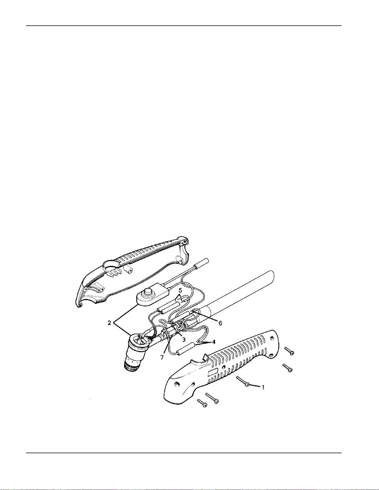
5-10 MAX20 Instruction Manual
4
MAINTENANCE
4. Connect the two black wires from the torch lead to the butt splice connecting the black plunger wire to the torch
main body using the Sta-kon crimping tool.
5. Connect the Tyrap as shown.
6. Install the torch main body assembly and torch switch into one of the handle halves. While positioning the
handle halves together, be careful not to pinch any wires. Be especially careful around the torch switch
retainers.
7. Replace the five screws to secure the handle halves together. If the seams do not fit together tightly, remove the
screws and check for pinched wires.
Figure 5-3 PAC100/110 Torch Repair Kit Installation

MAX20 Instruction Manual 6-1
4
Section 6
PARTS LIST
In this section:
PAC110 Torch Assembly and Leads .........................................................................................................................6-2
MAX20 CE Power Supply.........................................................................................................................................6-3
System Descriptions ........................................................................................................................................6-3
MAX20 CE Parts .............................................................................................................................................6-3

6-2 MAX20 Instruction Manual
4
PARTS LIST
PAC110 Torch Assembly and Leads
Part Number Description
070003 PAC110 Torch Assembly w/4.5 meter (15 ft. lead)
070014 PAC110 Torch Assembly w/7.5 meter (25 ft. lead)
020218 Retaining Cap
220013 Swirl Ring
020382 Electrode, Extended
020220 Electrode
020381 Nozzle, Extended
020299 Nozzle
026016 O-Ring
028349 Spare Parts Kit
220013 Swirl Ring (1)
020382 Electrode, Extended (3)
020381 Nozzle, Extended (5)
026016 O-Ring (2)
Figure 6-1 PAC110 Torch

MAX20 Instruction Manual 6-3
4
PARTS LIST
MAX20 CE Power Supply – (070049)
System Descriptions
070045 MAX20 CE System, PAC110 Torch, 200/220/240-Volt, 1 PH, 50/60 Hz, 4.5 meter (15-ft) Torch Leads,
3 meter (9-ft) Primary Cable
070046 MAX20 CE System, PAC110 Torch, 200/220/240-volt, 1 PH, 50/60 Hz, 7.5 meter (25-ft) Torch Leads,
3 meter (9-ft) Primary Cable
MAX20 CE Parts
Indicated below are the MAX20 CE components and subassemblies (see Figure 6-2).
Part
Item Qty Number Description
1 129045 Cover, SA MAX20 CE
1 1 001562 Cover, MAX20 CE
2 1 001197 Handle, 20/42R
3 1 029515 Gas supply, subassembly, MAX20E
4 1 011039 Filter, regulator, 5 Micron, 120 psi
1 011054* Filter element (used with 011039)
5 1 022019 Gauge, pressure, 0-100 psig, 1-1/2"
6 1 027106 Finger guard for 027103, 027116
7 1 008513 Hole plug
8 1 027116 Fan, TX, 220/230 VAC 50/60 Hz 34 SCFH
9 1 008412 Cord grip, 14-3 cord
10 3 074123 Wire tip, 14 AWG x .323 insulated
11 1 023293 Line cord, 20A, 220-240
12 2 074015 Terminal, 16-14 .250 QC , insulated, female
13 1 074067 Terminal, 22-18, .25 MAL QC insulated
14 2 008408 Standoff, 6-32 x 5/8"
15 1 008411 Terminal block, 6-pos
16 1 002196 Linkboard, 20A, 200-220-240V
17 2 004454 Spacer, 8-32 x 3.20" AL HX
18 1 004309 Link, 20A, 220-240V, 50/60 Hz
19 1 029516 Linkboard subassembly, 20A, 200-220-240V, 50-60 Hz
20 2 027038 Nut, pem KFS2-632
21 1 002172 Shield, safety, linkboard, 20A
22 1 014086 Inductor, 6 MHY, 20A CLS H UL/CSA- 1X
23 4 008379 Bumper, rubber molded in washer
24 1 003079 Relay, solder tab, DPDT 24 VAC
25 4 001219 Shield, 3-term 20A 200/220/240
26 1 008413 Terminal strip, 3-pos
27 2 009476 Resistor, 1 ohm, 20W, 5%
28 2 008398 Standoff, 6-32 x 1/2", nylon
1 129043 Relay SA, soft start MAX20 CE
29 1 041141 PC board assembly, In-rush, 20A, 220V
30 1 041140 PC board only, in-rush 20A, 220V
31 1 003084 Relay, 30A, SPST 220-240VAC, 50-60 Hz
32 1 005044 Switch, toggle SPDT SC TM MNT ON/ON

6-4 MAX20 Instruction Manual
4
PARTS LIST
33 1 005112 Switch, pressure 39 psi, .013 BAF
34 1 015540 Tee, 1/8
35 2 015517 Nipple, 1/8 x CL, hex
36 1 006055 Valve, solenoid, 24VAC, 70 psi
37 1 015151 Adapter, st, 1/8 NPT x 3/16 tube
1 129110 Switch SA, MAX20 CE
38 1 003180 Circuit breaker, 3P 240V/Rocker QDisc
38A 2 009951 Capacitor, .01 µf 500 VAC ceramic
38B 1 009966 Capacitor, .1 µf 300 X1-type metallized paper
39 1 004293 Plate, antirotation
40 1 008246 Bushing, 1.000 hole x 3/4" ID
41 1 001600 Base, MAX20 CE
42 1 009382 Light, pilot green LED 24 VAC .187 QDisc
43 1 009375 Light, pilot yellow LED 24 VAC .187 QDisc
44 1 008381 Strain relief, Anode Lead
45 1 008965 Knob, .850 diameter BLK/NAT 1/4" SFT
46 1 008382 Clamp, anode lead, copper, 40A
47 1 023269 Lead, anode, 4.5 meter (15 Ft.)
48 1 014196 Transformer, CE 3KVA 50 Hz, 200-220-240/50
49 1 129112 Chopper SA, 20A 250 OCV, MAX20 CE
50 1 004291 Spacer, chopper SA, MAX20
51 1 003078 Relay, 30A No mag blowout AC TM
* Filter element 011054 can also be obtained by contacting the local Hypertherm distributor.
MAX20 CE Parts (continued)
Part
Item Qty Number Description

MAX20 Instruction Manual 6-5
4
PARTS LIST
7
40
49
2
1
4
3
5
6
25
22
10
11
9
8
20
14
19
17
16
21
18
15
31
26
24
23
34
29
35
36
30
37
32
33
27
28
39
38
45
41
47
46
48
13
12
Figure 6-2 MAX20 – Exploded View
38A
38B
42
43
44
51
50

6-6 MAX20 Instruction Manual
4
PARTS LIST

MAX20 Instruction Manual 7-1
4
Section 7
WIRING DIAGRAMS
In this section:
Wiring Diagram .........................................................................................................................................................7-3

7-2 MAX20 Instruction Manual
4
WIRING DIAGRAMS

MAX20 Instruction Manual 7-3
4
WIRING DIAGRAMS
TORCH
CATHODE-BLK
BLK
ORN
19
1CR
AMPS
1POT
WHT BLU
+
-
BLKBLK
AC
CHOPPER SA
1T
240
220
BRN
BRN
BLU
240V
~
3CR
1FAN
BLK
BRN
BLK
1-4D
AC
200
0
173V
~
+
1CAP
RED
+
1TAS
GRY
2TAS-1T
YEL
2RES
1RES
3RES
4RES
CRE
18
BLK
RED
BLU
ANODE-BLK
22
2CR
WHT/ORN
PILOT ARC-RED
BLK
CAP ON
N.O. TO
CLOSE
PLASMA
START
23
BLU
21
VIO
GRY
17
16
WHT
24V
~
~
1415
WHT
BLU/WHT
WHT/RED
G
111213
WHT
REDWHT/RED
3A
G
7
89
WHT
RED
WHT
1CR
10
BLU
4
RED/WHT
N.O.
VIO
5
6
N.C.
RED
VIO
20
VIO
1
1PL
YELYEL/BLK
23
1TG
S
COIL
TEST
2TGS
RUN
1SOL
GAS
2CR
2LT
TEMP/
1PS
PRESSURE
1LT
POWER
1XBLK
1PL-21PL-1
(N)
BLU
1PH
220V
50-60HZ
200V
BRN
1TB 1TGS
BRN
3CRBRN
5RES
2PCB
6RES
50
60
200
220
240

7-4 MAX20 Instruction Manual
4
WIRING DIAGRAMS
 Loading...