

Page 1

Remote
Switch
MAX40 & HT40C,
MAX100, MAX200
Installation Manual
800820 - Revision 2
Page 2

Page 3

®
Remote Switch
MAX40 & HT40C, MAX100, MAX200
P/N 028328
Installation Manual
IM-82
(P/N 800820)
Revision 2 July, 1999
Hypertherm, Inc.
Hanover, NH
http://www.hypertherm.com
email:info@hypertherm.com
© Copyright 1999 Hypertherm, Inc.
All Rights Reserved
Hypertherm, HyDefinition, HT, HyLife, LongLife, MAX, PAC and Powermax are trademarks of Hypertherm, Inc.,
and may be registered in the United States and/or other countries
Page 4

Hypertherm Offices Worldwide:
Hypertherm, Inc.
Etna Road, P.O. Box 5010
Hanover, NH 03755 USA
Tel.: (603) 643-3441 (Main Office)
Fax: (603) 643-5352 (All Departments)
Tel.: (800) 643-9878 (Technical Service)
Tel.: (800) 737-2978 (Customer Service)
email: info@hypertherm.com (General Information)
email: service@hypertherm.com (Technical/Customer Services)
Hypertherm Plasmatechnik GmbH
Technologiepark Hanau
Rodenbacher Chaussee 6
D–63457 Hanau-Wolfgang, Germany
Tel.: 49 6181 58 2100
Fax: 49 6181 58 2134
European Technical Support Organization (ETSO)
Technologiepark Hanau
Rodenbacher Chaussee 6
D–63457 Hanau-Wolfgang, Germany
Tel.: 49 6181 58 2100
Fax: 49 6181 58 2134
Hypertherm Singapore Pte Ltd
No. 19 Kaki Bukit Road 2
K.B. Warehouse Complex
Singapore 417847, Republic of Singapore
Tel.: 65 841 2489
Fax: 65 841 2490
Hypertherm U.K.
9 Berkeley Court • Manor Park
Runcorn, Cheshire, England WA7 1TQ
Tel.: 44 1928 579 074
Fax: 44 1928 579 604
France
10, Allée de I’lsara
F-95000 Cergy-Pontoise, France
Tel.: 33 1 34 24 03 05
Fax: 33 1 34 25 09 64
Italy
Via Torino 2
20123 Milan, Italy
Tel.: 39 02 725 46 312
Fax: 39 02 725 46 400
Page 5

INSTALLATION
INSTALLATION
In this manual:
Remote Switch Installation - MAX40 & HT40C .................................2
Remote Switch Installation - MAX100 ..................................................3
Remote Switch Installation - MAX200 ..................................................4
Remote Switch Assembly and Schematic ............................................5
Remote Switch Installation Manual
Page 5
Page 6
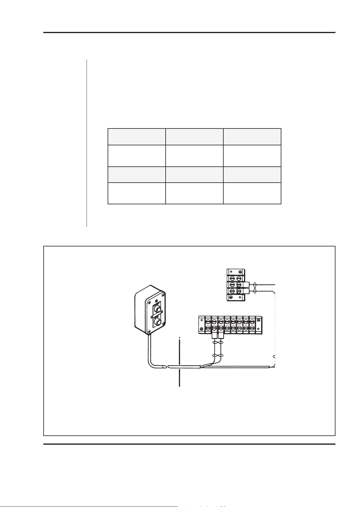
Remote Switch Installation - MAX40 & HT40C
To install the remote switch on the MAX40 or HT40C plasma system, perform the following
procedure and see Figure 1. See Figure 4 for additional information.
1. Remove the rear cover of the power supply.
2. Feed the remote switch cable through the torch lead hole at the rear of the power
supply. Locate terminal strips 1TB and 2TB on the right side of the center panel.
Connect the remote switch wire pairs to 2TB and 1TB as follows:
riaPeriW BT2 emaNlangiS
INSTALLATION
)43(kcalB
)33(deR
43
33
riaPeriW BT1 emaNlangiS
)83(kcalB
)73(etihW
3. Replace and secure the rear cover.
1TB
1
2
2TB
33 33
34 34
1 1 2 2 2 3 4
4
tratSamsalP
tratSamsalP
toHCAV42
tueNCAV42
RED
BLK
Figure 1 Remote Switch Installation - MAX40 & HT40C
Remote Switch Installation Manual
1
38 37
BLK
WHT
2 2 3 4 4
Page 6
Page 7
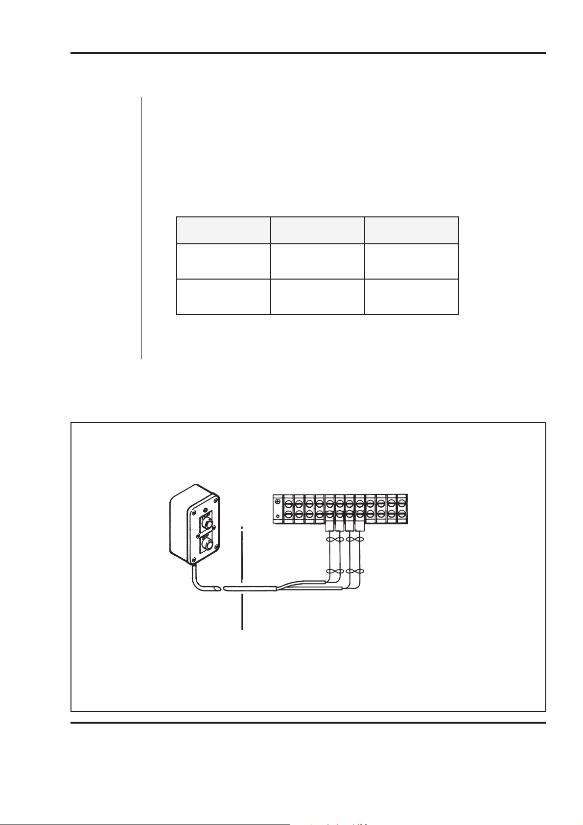
Remote Switch Installation - MAX100
sriaPeriW BT1 emaNlangiS
)43(kcalB
)33(deR
43
33
tratSamsalP
tratSamsalP
)83(kcalB
)73(etihW
83
73
toHCAV42
tueNCAV42
To install the remote switch on the MAX100 plasma system, perform the following procedure
and see Figure 2. See Figure 4 for additional information.
1. Remove the left side cover of the power supply.
2. Feed the remote switch cable through the strain relief at the rear of the power supply. Locate terminal strip 1TB on the rear center panel, left side. Connect the
remote switch wire pairs to 1TB as follows:
INSTALLATION
3. Replace and secure the left side cover.
1 2 39 42 34 33 37 38 35 36
1TB
38
373334
BLK
RED
WHT
BLK
Figure 2 Remote Switch Installation - MAX100
Remote Switch Installation Manual
Page 7
Page 8

Remote Switch Installation - MAX200
To install the remote switch on the MAX200 plasma system, perform the following procedure
and see Figure 3. See Figure 4 for additional information.
1. Remove the right side cover of the power supply.
2. Feed the remote switch cable through the feed-through at the rear of the power
supply. Locate terminal strips TB3 and TB4 on the inside rear panel, right side.
Connect the remote switch wire pairs to TB3 and TB4 as follows:
riaPeriW 3BT emaNlangiS
INSTALLATION
)43(kcalB
)33(deR
28
38
riaPeriW 4BT emaNlangiS
)83(kcalB
)73(etihW
3. Replace and secure the right side cover.
TB4
67
77
BLK
WHT
34 35
34 35 76 77 88 89
61 60 78 79 80 81 82 83 84 85 86 87
38
37
tratSamsalP
tratSamsalP
toHCAV42
tueNCAV42
88 89
TB3
Figure 3 Remote Switch Installation - MAX200
Remote Switch Installation Manual
61 60 78 79 80
81
34 33
84 85 86 87
BLK
RED
Page 8
Page 9

INSTALLATION
010350 LABEL010350 LABEL
OF TABOF TAB
NOTE ORIENTATIONNOTE ORIENTATION
(REF)(REF)
3333
3434
3737
3838
LABEL AS SHOWNLABEL AS SHOWN
LABEL AS SHOWNLABEL AS SHOWN
PENDANT ENDPENDANT END
ADD STRAIN RELIEF BEFORE TERMINATINGADD STRAIN RELIEF BEFORE TERMINATING
INSULATION, 1" FROM END.INSULATION, 1" FROM END.
ADD LARGE TYRAP AROUND CABLEADD LARGE TYRAP AROUND CABLE
008643008643
008070008070
002162 (REF)002162 (REF)
2 PLACES. 1" REF. FROM END OF WIRES.2 PLACES. 1" REF. FROM END OF WIRES.
ADD 1/8 SHRINKTUBE 1/2"LG OVER TWISTED WIRESADD 1/8 SHRINKTUBE 1/2"LG OVER TWISTED WIRES
074027 TERM.074027 TERM.
047055 CABLE 18-2 TWPR UNSH047055 CABLE 18-2 TWPR UNSH
074067 TERM.074067 TERM.
074016 TERM074016 TERM
002162 ENCLOSURE002162 ENCLOSURE
WHTWHT
REDRED
WHTWHT
3737
LT1LT1
1PB1PB
2PB2PB
MACHINE ENDMACHINE END
PENDANT ENDPENDANT END
3333
3434
3737
3838
4 PLACES4 PLACES
RA2217RA2217
074111074111
RA25177RA25177
BLKBLK
WHTWHT
BLKBLK
REDRED
REDRED
BLKBLK
WHTWHT
BLKBLK
BELDEN 9156BELDEN 9156
REAR VIEWREAR VIEW
COVERCOVER
CABLE DETAILCABLE DETAIL
SCHEMATICSCHEMATIC
WHTWHT
3737
STARTSTART
1PB1PB
3 53 5
1CR1CR
STOPSTOP
WHTWHT
2PB2PB
44
66
1CR1CR
REDRED
BLKBLK
3434
3333
3838
REDRED
AA BB
1LT1LT
RR
1CR1CR
010098 "STOP" PLATE010098 "STOP" PLATE
005122 RED PB.005122 RED PB.
010097 "START" PLATE010097 "START" PLATE
005121 GRN PB.005121 GRN PB.
005107 PILOT LIGHT-RED005107 PILOT LIGHT-RED
Remote Switch Installation Manual
Figure 4 Remote Switch Assembly and Schematic
Page 9
2-01
 Loading...