


Powermax105 SYNC™
Service Parts and Procedures Guide
810450 – REVISION 0
ENGLISH

Powermax, SYNC, SmartSYNC, and Hypertherm are trademarks of Hypertherm, Inc. and may be registered in the United States
and other countries. All other trademarks are the property of their respective holders.
Environmental stewardship is one of Hypertherm’s core values, and it is critical to our success and our customers’ success. We
are striving to reduce the environmental impact of everything we do. For more information:www.hypertherm.com/environment.
© 2021 Hypertherm, Inc.
100% Associate-owned

Powermax105 SYNC
Service Parts and Procedures Guide
810450
REVISION 0
ENGLISH
Original instructions
October 2021
Hypertherm, Inc.
Hanover, NH 03755 USA
www.hypertherm.com

Hypertherm, Inc.
21 Great Hollow Road, P.O. Box 5010
Hanover, NH 03755 USA
603-643-3441 Tel (Main Office)
603-643-5352 Fax (All Departments)
info@hypertherm.com (Main Office)
800-643-9878 Tel (Technical Service)
technical.service@hypertherm.com (Technical Service)
800-737-2978 Tel (Customer Service)
customer.service@hypertherm.com (Customer Service)
Hypertherm México, S.A. de C.V.
52 55 5681 8109 Tel
52 55 5681 7978 Tel
soporte.tecnico@hypertherm.com (Technical Service)
Hypertherm Plasmatechnik GmbH
Sophie-Scholl-Platz 5
63452 Hanau
Germany
00 800 33 24 97 37 Tel
00 800 49 73 73 29 Fax
31 (0) 165 596900 Tel (Technical Service)
00 800 4973 7843 Tel (Technical Service)
technicalservice.emeia@hypertherm.com (Technical Service)
Hypertherm (Singapore) Pte Ltd.
Solaris @ Kallang 164
164 Kallang Way #03-13
Singapore 349248, Republic of Singapore
65 6841 2489 Tel
65 6841 2490 Fax
marketing.asia@hypertherm.com (Marketing)
techsupportapac@hypertherm.com (Technical Service)
Hypertherm Japan Ltd.
Level 9, Edobori Center Building
2-1-1 Edobori, Nishi-ku
Osaka 550-0002 Japan
81 6 6225 1183 Tel
81 6 6225 1184 Fax
htjapan.info@hypertherm.com (Main Office)
techsupportapac@hypertherm.com (Technical Service)
Hypertherm Europe B.V.
Vaartveld 9, 4704 SE
Roosendaal, Nederland
31 165 596907 Tel
31 165 596901 Fax
31 165 596908 Tel (Marketing)
31 (0) 165 596900 Tel (Technical Service)
00 800 4973 7843 Tel (Technical Service)
technicalservice.emeia@hypertherm.com (Technical Service)
Hypertherm (Shanghai) Trading Co., Ltd.
B301, 495 ShangZhong Road
Shanghai, 200231
PR China
86-21-80231122 Tel
86-21-80231120 Fax
86-21-80231128 Tel (Technical Service)
techsupport.china@hypertherm.com (Technical Service)
South America & Central America: Hypertherm Brasil Ltda.
Rua Bras Cubas, 231 – Jardim Maia
Guarulhos, SP – Brasil
CEP 07115-030
55 11 2409 2636 Tel
tecnico.sa@hypertherm.com (Technical Service)
Hypertherm Korea Branch
#3904. APEC-ro 17. Heaundae-gu. Busan.
Korea 48060
82 (0)51 747 0358 Tel
82 (0)51 701 0358 Fax
marketing.korea@hypertherm.com (Marketing)
techsupportapac@hypertherm.com (Technical Service)
Hypertherm Pty Limited
GPO Box 4836
Sydney NSW 2001, Australia
61 7 3103 1695 Tel
61 7 3219 9010 Fax
au.sales@hypertherm.com (Main Office)
techsupportapac@hypertherm.com (Technical Service)
Hypertherm (India) Thermal Cutting Pvt. Ltd
A-18 / B-1 Extension,
Mohan Co-Operative Industrial Estate,
Mathura Road, New Delhi 110044, India
91-11-40521201/ 2/ 3 Tel
91-11 40521204 Fax
htindia.info@hypertherm.com (Main Office)
technicalservice.emeia@hypertherm.com (Technical Service)
For training and education resources, go to the Hypertherm Cutting Institute (HCI) online at
www.hypertherm.com/hci.

ENGLISH
WARNING! Before operating any Hypertherm equipment, read the safety
instructions in your product’s manual, the Safety and Compliance Manual (80669C),
Waterjet Safety and Compliance Manual (80943C), and Radio Frequency Warning
Manual (80945C). Failure to follow safety instructions can result in personal injury
or in damage to equipment.
Copies of the manuals can come with the product in electronic and printed formats.
Electronic copies are also on our website. Many manuals are available in multiple
languages at www.hypertherm.com/docs.
FR (FRANÇAIS/FRENCH)
AVERTISSEMENT! Avant d’utiliser tout équipement Hypertherm, lire les consignes
de sécurité dumanuel de votre produit, duManuel de sécurité et de conformité
(80669C), du Manuel de sécurité et de conformité du jet d’eau (80943C)
et du Manuel d'avertissement relatif aux radiofréqunces (80945C).
Les exemplaires des manuels qui accompagnent le produit peuvent être sous forme
électronique ou papier. Les manuels sous forme électronique se trouvent également
sur notre site Internet. Plusieurs manuels sont offerts en plusieurs langues
à www.hypertherm.com/docs.
BG (БЪЛГAPCКИ/BULGARIAN)
ПРЕДУПРЕЖДЕНИЕ! Преди да работите с което и да е оборудване
Hypertherm, прочетете инструкциите за безопасност в ръководството на вашия
продукт, „Инструкция за безопасност и съответствие“ (80669C), „Инструкция
за безопасност и съответствие на Waterjet“ (80943С) и „Инструкция
за предупреждение за радиочестота“ (80945С).
Продуктът може да е съпроводен от копия на ръководствата в електронен
и в печатен формат. Тези в електронен формат са достъпни също на уебсайта
ни. Много ръководства са налице на няколко езика
на адрес www.hypertherm.com/docs.
CS (ČESKY/CZECH)
VAROVÁNÍ! Před uvedením jakéhokoli zařízení Hypertherm do provozu si přečtěte
bezpečnostní pokyny v příručce k produktu a v Manuálu pro bezpečnost
a dodržování předpisů (80669C), Manuálu pro bezpečnost a dodržování
předpisů při řezání vodním paprskem (80943C) a Manuálu varování ohledně
rádiových frekvencí (80945C).
Kopie příruček mohou být součástí dodávky produktu, a to v elektronické i tištěné
formě. Elektronické kopie jsou k dispozici i na našich webových stránkách. Mnoho
příruček je k dispozici v různých jazycích na stránce www.hypertherm.com/docs.
DA (DANSK/DANISH)
ADVARSEL! Inden Hypertherm udstyr tages i brug skal sikkerhedsinstruktionerne
i produktets manual og i Manual om sikkerhed og overholdelse af krav (80669C),
Manual om sikkerhed og overholdelse af krav for vandstråleskæring (80943C),
og Manual om radiofrekvensadvarsel (80945C), gennemlæses.
Kopier af manualerne kan leveres med produktet i elektronisk og trykt format.
Elektroniske kopier findes også på vores hjemmeside. Mange manualer
er tilgængelige på flere sprog på www.hypertherm.com/docs.
DE (DEUTSCH/GERMAN)
WARNUNG! Bevor Sie ein Hypertherm-Gerät in Betrieb nehmen, lesen Sie bitte die
Sicherheitsanweisungen in Ihrer Bedienungsanleitung, das Handbuch für Sicherheit
und Übereinstimmung (80669C), das Handbuch für Sicherheit und Compliance bei
Wasserstrahl-Schneidanlagen (80943C) und das Handbuch für HochfrequenzWarnung (80945C).
Bedienungsanleitungen und Handbücher können dem Gerät in elektronischer Form
oder als Druckversion beiliegen. In elektronischer Form liegen sie auch auf unserer
Website vor. Viele Handbücher stehen in verschiedenen Sprachen auf
www.hypertherm.com/docs zur Verfügung.
ES (ESPAÑOL/SPANISH)
¡ADVERTENCIA! Antes de operar cualquier equipo Hypertherm, lea las
instrucciones de seguridad del manual de su producto, del Manual de seguridad
y cumplimiento (80669C), del Manual de seguridad y cumplimiento en corte con
chorro de agua (80943C) y del Manual de advertencias de radiofrecuencia
(80945C).
El producto puede incluir copias de los manuales en formato digital e impreso.
Las copias digitales también están en nuestra página web. Hay diversos manuales
disponibles en varios idiomas en www.hypertherm.com/docs.
ET (EESTI/ESTONIAN)
HOIATUS! Enne Hyperthermi mis tahes seadme kasutamist lugege läbi toote
kasutusjuhendis olevad ohutusjuhised ning Ohutus- ja vastavusjuhend (80669C),
Veejoa ohutuse ja vastavuse juhend (80943C) ja Raadiosageduse hoiatusjuhend
(80945C). Ohutusjuhiste eiramine võib põhjustada vigastusi ja kahjustada
seadmeid.
Juhiste koopiad võivad tootega kaasas olla elektrooniliselt või trükituna.
Elektroonilised koopiad on saadaval ka meie veebilehel. Paljud kasutusjuhendid
on erinevates keeltes saadaval veebilehel www.hypertherm.com/docs.
FI (SUOMI/FINNISH)
VAROITUS! Ennen minkään Hypertherm-laitteen käyttöä lue tuotteen
käyttöoppaassa olevat turvallisuusohjeet, turvallisuuden ja vaatimustenmukaisuuden
käsikirja (80669C), vesileikkauksen turvallisuuden ja vaatimustenmukaisuuden
käsikirja (80943C) ja radiotaajuusvaroitusten käsikirja (80945C).
Käyttöoppaiden kopiot voivat olla tuotteen mukana sähköisessä ja tulostetussa
muodossa. Sähköiset kopiot ovat myös verkkosivustollamme. Monet käyttöoppaat
ovat myös saatavissa useilla kielillä www.hypertherm.com/docs.
GR (ΕΛΛΗΝΙΚΆ/GREEK)
ΠΡΟΕΙΟΠΟΙΗΣΗ! Πριν θέσετε σε λειτουργία οποιονδήποτε εξοπλισό της
Hypertherm, διαβάστε τις οδηγίες ασφαλείας στο εγχειρίδιο του προϊόντος και στο
εγχειρίδιο ασφάλειας και συμμόρφωσης (80669C), στο εγχειρίδιο ασφάλειας και
συμμόρφωσης του waterjet (80943C) και στο εγχειρίδιο προειδοποιήσεων για τις
ραδιοσυχνότητες (80945C).
Το προϊόν πορεί να συνοδεύεται από αντίγραφα των εγχειριδίων σε ηλεκτρονική
και έντυπη ορφή. Τα ηλεκτρονικά αντίγραφα υπάρχουν επίσης στον ιστότοπό ας.
Πολλά εγχειρίδια είναι διαθέσια σε διάφορες γλώσσες στο
www.hypertherm.com/docs.
HU (MAGYAR/HUNGARIAN)
VIGYÁZAT! Mielőtt bármilyen Hypertherm berendezést üzemeltetne,
olvassa el a biztonsági információkat a termék kézikönyvében, a Biztonsági
és szabálykövetési kézikönyvben (80669C), a Vízsugaras biztonsági
és szabálykövetési kézikönyvben (80943C) és a Rádiófrekvenciás
figyelmeztetéseket tartalmazó kézikönyvben (80945C).
A termékhez a kézikönyv példányai elektronikus és nyomtatott formában is mellékelve
lehetnek. Az elektronikus példányok webhelyünkön is megtalálhatók. Számos
kézikönyv áll rendelkezésre több nyelven a www.hypertherm.com/docs weboldalon.
ID (BAHASA INDONESIA/INDONESIAN)
PERINGATAN! Sebelum mengoperasikan peralatan Hypertherm, bacalah petunjuk
keselamatan dalam manual produk Anda, Manual Keselamatan dan Kepatuhan
(80669C), Manual Keselamatan dan Kepatuhan Jet Air (80943C), dan Manual
Peringatan Frekuensi Radio (80945C). Kegagalan mengikuti petunjuk keselamatan
dapat menyebabkan cedera pribadi atau kerusakan pada peralatan.
Produk mungkin disertai salinan manual atau petunjuk dalam format elektronik
maupun cetak. Salinan elektronik juga tersedia di situs web kami. Berbagai manual
tersedia dalam beberapa bahasa di www.hypertherm.com/docs.
IT (ITALIANO/ITALIAN)
AVVERTENZA! Prima di usare un’attrezzatura Hypertherm, leggere le istruzioni sulla
sicurezza nel manuale del prodotto, nel Manuale sulla sicurezza e la conformità
(80669C), nel Manuale sulla sicurezza e la conformità Waterjet (80943C) e nel
Manuale di avvertenze sulla radiofrequenza(80945C).
Copie del manuale possono accompagnare il prodotto in formato cartaceo
o elettronico. Le copie elettroniche sono disponibili anche sul nostro sito web. Molti
manuali sono disponibili in diverse lingue all’indirizzo www.hypertherm.com/docs.
JA (日本語/JAPANESE)
警告 ! Hypertherm 機器を操作する前に、この製品説明書にある安全情報、「安全
とコンプライアンスマニュアル」 (80669C) 、「ウォータージェットの安全とコ
ンプライアンス」 (80943C)、「高周波警告」 (80945C) をお読みください。
説明書のコピーは、電子フォーマット、または印刷物として製品に同梱されて
います。電子コピーは当社ウェブサイトにも掲載されています。説明書の多く
は www.hypertherm.com/docs にて複数の言語でご用意しています。
KO (한국어 /KOREAN)
경고! Hypertherm 장비를 사용하기 전에 제품 설명서와 안전 및 규정 준수
설명서(80669C), 워터젯 안전 및 규정 준수 설명서(80943C) 그리고 무선 주파수
경고 설명서(80945C)에 나와 있는 안전 지침을 읽으십시오.
전자 형식과 인쇄된 형식으로 설명서 사본이 제품과 함께 제공될 수 있습니다.
전자 사본도 Hypertherm 웹사이트에서 보실 수 있으며 설명서 사본은
www.hypertherm.com/docs 에서 여러 언어로 제공됩니다.
NE (NEDERLANDS/DUTCH)
WAARSCHUWING! Lees voordat u Hypertherm-apparatuur gebruikt
de veiligheidsinstructies in de producthandleiding, in de Veiligheids-
en nalevingshandleiding (80669C) in de Veiligheids- en nalevingshandleiding
voor waterstralen (80943C) en in de Waarschuwingshandleiding radiofrequentie
(80945C).
De handleidingen kunnen in elektronische en gedrukte vorm met het product worden
meegeleverd. Elektronische versies zijn ook beschikbaar op onze website. Veel
handleidingen zijn in meerdere talen beschikbaar via www.hypertherm.com/docs.

NO (NORSK/NORWEGIAN)
ADVARSEL! Før du bruker noe Hypertherm-utstyr, må du lese
sikkerhetsinstruksjonene i produktets håndbok, håndboken om sikkerhet og
samsvar (80669C), håndboken om vannjet sikkerhet og samsvar (80943C),
og håndboken om radiofrekvensadvarsler (80945C).
Eksemplarer av håndbøkene kan følge med produktet i elektronisk og trykt form.
Elektroniske eksemplarer finnes også på nettstedet vårt. Mange håndbøker
er tilgjengelig i flere språk på www.hypertherm.com/docs.
SV (SVENSKA/SWEDISH)
VARNING! Läs häftet säkerhetsinformationen i din produkts säkerhets- och
efterlevnadsmanual (80669C), säkerhets- och efterlevnadsmanualen för Waterjet
(80943C) och varningsmanualen för radiofrekvenser (80945C) för viktig
säkerhetsinformation innan du använder eller underhåller Hypertherm-utrustning.
Kopior av manualerna kan medfölja produkten i elektroniskt och tryckt format.
Elektroniska kopior finns också på vår webbplats. Många manualer finns på flera
språk på www.hypertherm.com/docs.
PL (POLSKI/POLISH)
OSTRZEŻENIE! Przed rozpoczęciem obsługi jakiegokolwiek systemu
firmy Hypertherm należy się zapoznać z instrukcjami bezpieczeństwa zamieszczonymi
w podręczniku produktu, w podręczniku bezpieczeństwa i zgodności (80669C),
podręczniku bezpieczeństwa i zgodności systemów strumienia wody (80943C)
oraz podręczniku z ostrzeżeniem o częstotliwości radiowej (80945C).
Do produktu mogą być dołączone podręczniki użytkownika wformie elektronicznej
idrukowanej. Kopie elektroniczne znajdują się również wnaszej witrynie internetowej.
Wiele podręczników jest dostępnych wróżnych językach pod adresem
www.hypertherm.com/docs.
PT (PORTUGUÊS/PORTUGUESE)
ADVERTÊNCIA! Antes de operar qualquer equipamento Hypertherm,
leia as instruções de segurança no manual do seu produto, no Manual
de Segurança e de Conformidade (80669C), no Manual de Segurança
e de Conformidade do Waterjet (80943C) e no Manual de Advertência
de radiofrequência (80945C).
Cópias dos manuais podem vir com o produto nos formatos eletrônico e impresso.
Cópias eletrônicas também são encontradas em nosso website. Muitos manuais
estão disponíveis em vários idiomas em www.hypertherm.com/docs.
RO (ROMÂNĂ/ROMANIAN)
AVERTIZARE! Înainte de utilizarea oricărui echipament Hypertherm, citii
instruciunile de sigurană din manualul produsului, manualul de siguranță
și conformitate (80669C), manualul de siguranță și conformitate Waterjet (80943C)
și din manualul de avertizare privind radiofrecvența (80945C).
Produsul poate fi însoit de copii ale manualelor în format tipărit și electronic.
Exemplarele electronice sunt disponibile și pe site-ul nostru web.
Numeroase manuale sunt disponibile în mai mult limbi la adresa:
www.hypertherm.com/docs.
RU (PУССКИЙ/RUSSIAN)
БЕРЕГИСЬ! Перед работой с любым оборудованием Hypertherm ознакомьтесь
с инструкциями по безопасности, представленными в руководстве, которое
поставляется вместе с продуктом, в Руководстве по безопасности и
соответствию (80669С), в Руководстве по безопасности и соответствию для
водоструйной резки (80943C) и Руководстве по предупреждению о
радиочастотном излучении (80945С).
Копии руководств, которые поставляются вместе с продуктом, могут быть
представлены в электронном и бумажном виде. Электронные копии также
доступны на нашем веб-сайте. Целый ряд руководств доступны на нескольких
языках по ссылке www.hypertherm.com/docs.
SK (S LOVENČINA/SLOVAK)
VÝSTRAHA! Pred použitím akéhokoľvek zariadenia od spoločnosti Hypertherm si
prečítajte bezpečnostné pokyny v návode na obsluhu vášho zariadenia a v Manuáli
o bezpečnosti a súlade s normami (80669C), Manuáli o bezpečnosti a súlade
snormami pre systém rezania vodou (80943C) avManuáli sinformáciami
orádiofrekvencii (80945C).
Návod na obsluhu sa dodáva spolu sproduktom velektronickej atlačenej podobe.
Jeho elektronický formát je dostupný aj na našej webovej stránke. Mnohé znávodov
na obsluhu sú dostupné vo viacjazyčnej mutácii na stránke
www.hypertherm.com/docs.
TH (ภาษาไทย/THAI)
คําเตือน! กอนการใชงานอุปกรณของ Hypertherm ทั้งหมด โปรดอานคําแนะนําดานความ
ปลอดภัยในคูมือการใชสินคา คูมือดานความปลอดภัยและการปฏิบัติตาม (80669C), คูมือ
ดานความปลอดภัยและการปฏิบัติตามสําหรับการใชหัวตัดระบบวอเตอรเจ็ต (80943C)
และ คูมือคําเตือนเกี่ยวกับความถี่วิทยุ (80945C) การไมปฏิบัติตามคําแนะนําดานความ
ปลอดภัยอาจสงผลใหเกิดการบาดเจ็บหรือเกิดความเสียหายตออุปกรณ
สําเนาคูมือทั้งในรูปแบบอิเล็กทรอนิกสและแบบสิ่งพิมพจะถูกแนบมาพรอมกับ
ผลิตภัณฑ สําเนาคูมือในรูปแบบอิเล็กทรอนิกสของผลิตภัณฑและสําเนาคูมือตาง
ๆ ในหลากหลายภาษานั้นยังมีใหบริการบนเว็บไซต www.hypertherm.com/docs
ของเราอีกดวย
TR (TÜRKÇE/TURKISH)
UYARI! Bir Hypertherm ekipmanını çalıştırmadan önce, ürününüzün kullanım
kılavuzunda, Güvenlik ve Uyumluluk Kılavuzu’nda (80669C), Su Jeti Güvenlik
ve Uyumluluk Kılavuzu’nda (80943C) ve Radyo Frekansı Uyarısı Kılavuzu’nda
(80945C) yer alan güvenlik talimatlarını okuyun.
Kılavuzların kopyaları, elektronik ve basılı formatta ürünle birlikte verilebilir. Elektronik
kopyalar web sitemizde de yer alır. Kılavuzların birçoğu www.hypertherm.com/docs
adresinde birçok dilde mevcuttur.
VI (TIẾNG VIỆT/VIETNAMESE)
CẢNH BÁO! Trước khi vận hành bất kỳ thiết bị Hypertherm nào, hãy đọc các
hướng dẫn an toàn trong hướng dẫn sử dụng sản phẩm của bạn,
và Tuân thủ
dẫn Cảnh báo Tần số Vô tuyến
có thể dẫn đến thương tích cá nhân hoặc hư hỏng thiết bị.
Bản sao của sổ tay có thể đi kèm với sản phẩm ở định dạng điện tử và in. Bản
điện tử cũng có trên trang web của chúng tôi. Nhiều sổ tay có sẵn bằng nhiều
ngôn ngữ tại www.hypertherm.com/docs.
ZH-CN (简 体中文 /CHINESE SIMPLIFIED)
警告! 在操作任何海宝设备之前,请阅读产品手册、《安全和法规遵守手册》
(80669C)、《水射流安全和法规遵守手册》 (80943C) 以及 《射频警告手册》
(80945C) 中的安全操作说明。
随产品提供的手册可提供电子版和印刷版两种格式。电子版本同时也在我们的网
站上提供。很多手册有多种语言版本,详见 www.hypertherm.com/docs.
ZH-TW (繁 體中文/CHINESE TRADITIONAL)
警告!在操作任何Hypertherm設備前,請先閱讀您產品手冊內的安全指示,
包括 《安全和法規遵從手冊》(80669C)、《水刀安全和法規遵從手冊》
(80943C),以及 《無線電頻率警示訊號手冊》(80945C)。
電子版和印刷版手冊複本可能隨產品附上。您也可以前往我們的網站下載電子版
手冊。我們的網站上還以多種語言形式提供多種手冊,請造訪
www.hypertherm.com/docs。
(80669C),
Sổ tay An toàn và Tuân thủ Tia nước
(80945C). Không tuân thủ các hướng dẫn an toàn
Sổ tay An toàn
(80943C), và
Hướng
SL (S LOVENŠČINA/SLOVENIAN)
OPOZORILO! Pred uporabo katerekoli Hyperthermove opreme preberite varnostna
navodila v priročniku vašega izdelka, v Priročniku za varnost in skladnost (80669C),
v Priročniku za varnost in skladnost sistemov rezanja z vodnim curkom (80943C)
in v Priročniku Opozorilo o radijskih frekvencah (80945C).
Izvodi priročnikov so lahko izdelku priloženi v elektronski in tiskani obliki. Elektronski
izvodi so na voljo tudi na našem spletnem mestu. Številni priročniki so na voljo
v različnih jezikih na naslovu www.hypertherm.com/docs.
SR (SRPSKI/SERBIAN)
UPOZORENJE! Pre rukovanja bilo kojom Hyperthermovom opremom pročitajte
uputstva o bezbednosti u svom priručniku za proizvod, Priručniku o bezbednosti
i usaglašenosti (80669C), Priručniku o bezbednosti i usaglašenosti Waterjet
tehnologije (80943C) i Priručniku sa upozorenjem o radio-frekvenciji (80945C).
Уз производ се испоручују копије приручника у електронском или штампаном
формату. Електронске копије су такође доступне на нашем веб-сајту. Многи
приручници су доступни на више језика на адреси www.hypertherm.com/docs.

Contents
1 Before You Begin....................................................................................................................... 11
2 Service Parts ............................................................................................................................. 13
Plasma power supply exterior, front................................................................................................................ 14
Work leads................................................................................................................................................ 15
Powermax105 SYNC ................................................................................................................. 15
Plasma power supply exterior, rear................................................................................................................. 16
Power cord and strain relief.................................................................................................................. 17
Rear panel................................................................................................................................................. 18
Plasma power supply interior, rear.................................................................................................................. 19
Plasma power supply interior, fan side........................................................................................................... 20
Fan and fan shroud................................................................................................................................. 22
Plasma power supply interior, front................................................................................................................. 23
Front panel................................................................................................................................................ 24
Plasma power supply interior, power PCB side .......................................................................................... 25
Capacitors and DSP PCB.................................................................................................................... 26
Plasma power supply interior, heatsink.......................................................................................................... 27
105 A heatsink diode bridges .............................................................................................................. 27
105 A heatsink IGBTs and thermal sensor ....................................................................................... 28
IGBT tester............................................................................................................................................... 29
105 A heatsink resistors........................................................................................................................ 30
Power supply interior, magnetics..................................................................................................................... 31
Powermax105 SYNC Service Parts and Procedures 810450 7

Contents
Machine interface and RS-485 serial interface upgrade kits ................................................................... 32
External cables for machine interface receptacle and RS-485 serial interface receptacle .. 33
Machine interface cables ......................................................................................................... 33
RS-485 serial interface cables................................................................................................ 34
Powermax65/85/105 SYNC labels ................................................................................................................ 35
Cartridge labels ....................................................................................................................................... 35
CSA warning label.................................................................................................................................. 36
Descriptions of warning label icons.................................................................................................... 37
Parts necessary for safety................................................................................................................................. 38
Recommended spare parts .............................................................................................................................. 39
Find replacement parts by part number......................................................................................................... 40
3 Service Procedures for the Cover, Panels, and Connectors ............................................. 43
Tools necessary for this section....................................................................................................................... 44
More tools necessary for some procedures ..................................................................................... 44
Replace the plasma power supply cover and component barrier ........................................................... 45
Remove the plasma power supply cover and component barrier................................................ 45
Install the component barrier and plasma power supply cover.................................................... 47
Replace the end panel bracket........................................................................................................................ 49
Remove the end panel bracket ............................................................................................................ 49
Install the end panel bracket................................................................................................................. 50
Loosen and attach the front panel .................................................................................................................. 51
Loosen the front panel ........................................................................................................................... 51
Attach the front panel............................................................................................................................. 52
Loosen and attach the rear panel.................................................................................................................... 53
Loosen the rear panel ............................................................................................................................ 53
Attach the rear panel of the plasma power supply.......................................................................... 54
Replace the front panel...................................................................................................................................... 55
Remove the front panel.......................................................................................................................... 55
Install the front panel .............................................................................................................................. 55
Replace the rear panel....................................................................................................................................... 56
Remove the rear panel........................................................................................................................... 56
Install the rear panel ............................................................................................................................... 59
Replace the work lead connector ................................................................................................................... 63
Remove the work lead connector........................................................................................................ 63
Install the work lead connector............................................................................................................ 63
Replace the work lead receptacle .................................................................................................................. 65
Remove the work lead receptacle....................................................................................................... 65
Install the work lead receptacle ........................................................................................................... 66
Replace the torch quick-disconnect receptacle.......................................................................................... 67
Remove the torch quick-disconnect receptacle.............................................................................. 67
Install the torch quick-disconnect receptacle .................................................................................. 69
8 810450 Service Parts and Procedures Powermax105 SYNC

Contents
Replace the power switch................................................................................................................................. 71
Remove the power switch..................................................................................................................... 71
Install the power switch ......................................................................................................................... 72
4 Service Procedures for the Gas Line..................................................................................... 75
Tools necessary for this section....................................................................................................................... 76
More tools necessary for some procedures ..................................................................................... 76
Replace the air filter bowl and filter element................................................................................................. 77
Remove the air filter bowl and filter element..................................................................................... 77
Replace the air filter bowl, O-ring, and filter element ..................................................................... 78
Install the air filter bowl and filter element ......................................................................................... 79
Replace the air filter assembly ......................................................................................................................... 79
Remove the air filter assembly ............................................................................................................. 79
Install the air filter assembly.................................................................................................................. 80
Replace the fan and fan shroud....................................................................................................................... 81
Remove the fan and fan shroud........................................................................................................... 81
Install the fan and fan shroud ............................................................................................................... 83
Replace the solenoid valve ............................................................................................................................... 84
Remove the solenoid valve ................................................................................................................... 84
Install the solenoid valve........................................................................................................................ 85
Replace the gas tubes....................................................................................................................................... 87
Remove the gas tubes ........................................................................................................................... 87
Install the gas tubes................................................................................................................................ 87
Replace the 90° gas tube fitting...................................................................................................................... 88
5 Service Procedures for the PCBs and Related Components........................................... 89
Tools necessary for this section....................................................................................................................... 90
More tools necessary to for some procedures ................................................................................ 90
Replace the DSP PCB...................................................................................................................................... 91
Replace the control PCB and the ribbon cable........................................................................................... 92
Remove the control PCB and the ribbon cable............................................................................... 92
Install the control PCB and the ribbon cable................................................................................... 93
Replace the power PCB ................................................................................................................................... 94
Remove the power PCB ....................................................................................................................... 94
Install the power PCB............................................................................................................................ 98
Replace the heatsink components................................................................................................................ 102
Replace the output diode bridge....................................................................................................... 103
Replace the input diode bridge ......................................................................................................... 105
Replace the pilot arc IGBT................................................................................................................ 106
Replace the inverter IGBT and the thermal sensor...................................................................... 108
Powermax105 SYNC Service Parts and Procedures 810450 9

Contents
Replace the PFC IGBT ....................................................................................................................... 110
Replace the snubber resistors and the damper resistor............................................................. 112
How to clean the heatsink and apply thermal grease to the heatsink components ......................... 114
Remove the grease from the heatsink............................................................................................. 114
Apply the grease to the heatsink component................................................................................ 114
Replace the power PCB capacitors............................................................................................................ 115
Replace the bulk capacitors.......................................................................................................................... 117
Remove the bulk capacitors .............................................................................................................. 117
Install the bulk capacitors................................................................................................................... 120
6 Service Procedures for the Magnetics............................................................................... 121
Tools necessary for this section.................................................................................................................... 122
Replace the output inductor.......................................................................................................................... 123
Remove the output inductor .............................................................................................................. 123
Install the output inductor................................................................................................................... 124
Replace the transformer................................................................................................................................. 126
Remove the transformer ..................................................................................................................... 126
Install the transformer.......................................................................................................................... 127
Replace the PFC inductor ............................................................................................................................. 130
Remove the PFC inductor.................................................................................................................. 130
Install the PFC ...................................................................................................................................... 131
10 810450 Service Parts and Procedures Powermax105 SYNC

Before You Begin
This manual has service parts and procedures for the plasma power supply only. For torch service
parts and procedures, refer to SmartSYNC™ Service Parts and Procedures Guide (810460).
This manual helps you do the following:
Install replacement parts that you already have
Refer to Service Procedures for the Cover, Panels, and Connectors on page 43.
Refer to Service Procedures for the Gas Line on page 75.
Refer to Service Procedures for the PCBs and Related Components on page 89.
Refer to Service Procedures for the Magnetics on page 121.
Find the part number that you need to order
Refer to Service Parts on page 13.
Refer to Find replacement parts by part number on page 40.
For assistance with repairing or replacing internal components, do the following:
1. Get the serial number for your system from the data plate that is on the rear panel of the plasma
power supply.
2. Contact your Hypertherm distributor or authorized repair facility.
3. Contact the nearest Hypertherm office shown in the front of this manual.
Powermax105 SYNC Service Parts and Procedures 810450 11

Before You Begin
1
For related information, refer to the following documents:
Powermax65/85/105 SYNC Troubleshooting Guide (810430)
SmartSYNC™ Service Parts and Procedures Guide (810460) (hand torches and
mechanized torches for Powermax SYNC)
The most recent revisions of technical documentation are available at www.hypertherm.com/docs.
Technical documentation is current as of the date of its release.
Subsequent revisions are possible.
12 810450 Service Parts and Procedures Powermax105 SYNC

Service Parts
NOTICE
Genuine Hypertherm parts are factory-recommended parts for your Hypertherm system. Any damage
caused by the use of parts that are not from Hypertherm may not be covered by the Hypertherm
warranty.
This section gives a list of service parts for the plasma power supply. Many parts come as a kit that
contains 2 or more items.
To find part numbers with kit contents, by location, refer to the following:
Plasma power supply exterior, front on page 14
Plasma power supply exterior, rear on page 16
Plasma power supply interior, rear on page 19
Plasma power supply interior, fan side on page 20
Plasma power supply interior, front on page 23
Plasma power supply interior, power PCB side on page 25
Plasma power supply interior, heatsink on page 27
Power supply interior, magnetics on page 31
Machine interface and RS-485 serial interface upgrade kits on page 32
Powermax65/85/105 SYNC labels on page 35
To see a list of parts in order by part number, refer to Find replacement parts by part number on
page 40.
Powermax105 SYNC Service Parts and Procedures 810450 13
Service Parts
2
1
2
3
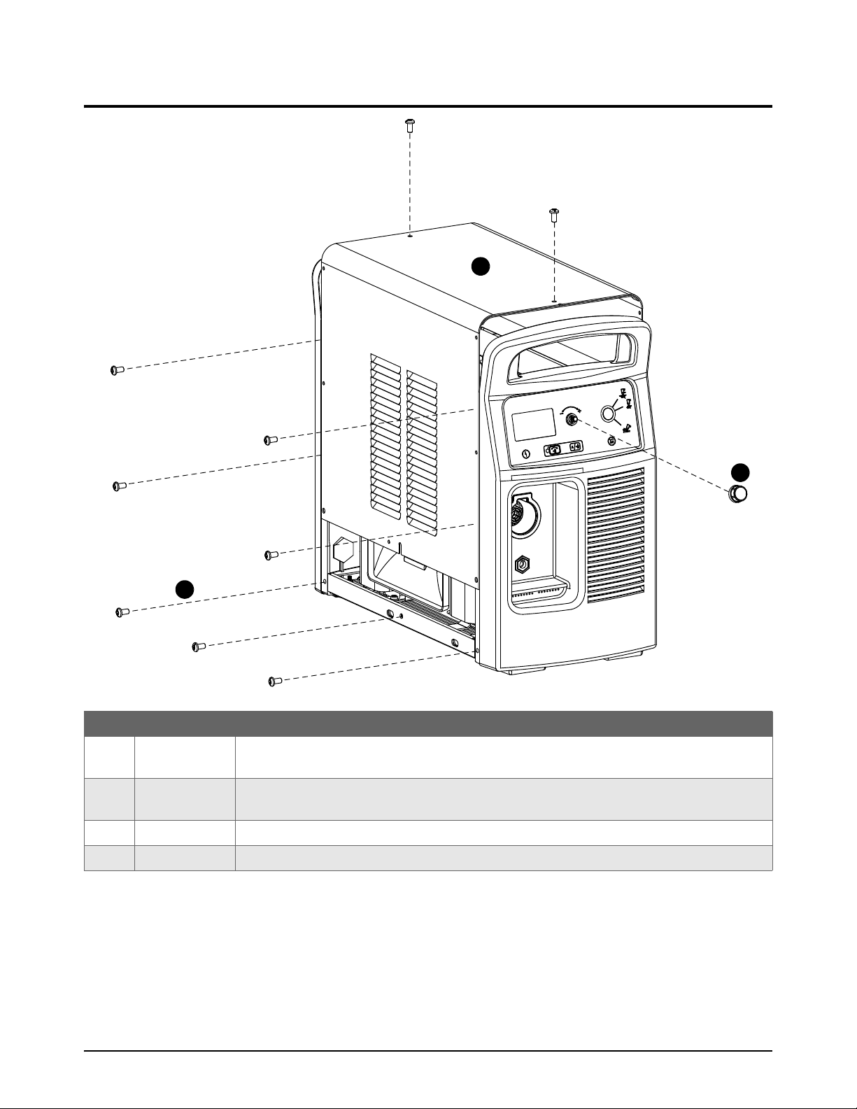
Plasma power supply exterior, front
Item Part number Description
1 528013 Kit: Powermax105 SYNC plasma power supply cover with labels, CSA (no screws
included)
1 528014 Kit: Powermax105 SYNC plasma power supply cover with labels, CE/CCC (no screws
included)
2 428143 Kit: Adjustment knob only
3 428141 Kit: Replacement screws (16) for plasma power supply cover
For replacement procedures, refer to Replace the plasma power supply cover and component
barrier on page 45.
14 810450 Service Parts and Procedures Powermax105 SYNC

Service Parts
2
Hand clamp C-style clamp Ring terminal
1
2 3
4
Work leads
NOTICE
Work leads are approved for specific amperages, lengths, and connectors. Make sure that you use a
work lead that is approved for your plasma power supply. The amperage of a work lead is identified
near the rubber boot of the work lead connector.
Powermax105 SYNC
Item Part number Description
1 223254 105 A work lead with hand clamp, 7.6 m (25 foot)
1 223255 105 A work lead with hand clamp, 15 m (50 foot)
1 223294 105 A / 125 A work lead with hand clamp, 23 m (75 foot)
2 223298 105 A / 125 A work lead with C-style clamp, 7.6 m (25 foot)
2 223299 105 A / 125 A work lead with C-style clamp, 15 m (50 foot)
2 223300 105 A / 125 A work lead with C-style clamp, 23 m (75 foot)
3 223284 105 A work lead with ring terminal, 7.6 m (25 foot)
3 223285 105 A work lead with ring terminal, 15 m (50 foot)
3 223297 105 A / 125 A work lead with ring terminal, 23 m (75 foot)
4 008337 Ground hand clamp: 300 A
228891 Kit: Work lead connector
You can make a work lead by installing the 008337 hand clamp on the
approved amperage ring terminal work lead from Hypertherm. Make sure
that you use a work lead that is the correct amperage for your plasma
power supply.
For replacement procedures, refer to Replace the work lead connector on page 63.
Powermax105 SYNC Service Parts and Procedures 810450 15

Service Parts
2
1
2
4
5
7
9
3
6
8
Plasma power supply exterior, rear
Item
Part
number
1 428352 Kit: Air filter bowl, polycarbonate (comes with plasma power supply, includes the O-ring but not
2* 428415 Kit: Air filter bowl, nylon (optional – for work sites with oily air) (includes the O-ring but not the
3 228695 Kit: Air filter element and O-ring (compatible with both filter bowl types)
4 428685 Kit: Gas inlet fittings
027055 Silicone lubricant, 0.25 ounces
* The polycarbonate filter bowl that comes with the plasma power supply is compatible with most gas supply
systems, but it is important to keep the gas line clean. Organic solvents, chemicals, cutting oil, synthetic oil, alkali,
and thread lock solutions can cause damage to the polycarbonate filter bowl over time. You can use the optional
nylon bowl (428415) if conditions at your work site make it difficult to prevent harsh chemicals from getting into the
gas line.
Description and kit contents
the filter element)
011124 Air filter bowl, polycarbonate
filter element)
011128 Air filter bowl, nylon
011093 Air filter element
011125 O-ring
015145 British Pipe Thread adapter G-1/4 BSPP with 1/4 NPT threads
015337 Industrial interchange quick-disconnect nipple with 1/4 NPT threads
For replacement procedures, refer to Replace the air filter bowl and filter element on page 77.
16 810450 Service Parts and Procedures Powermax105 SYNC
2
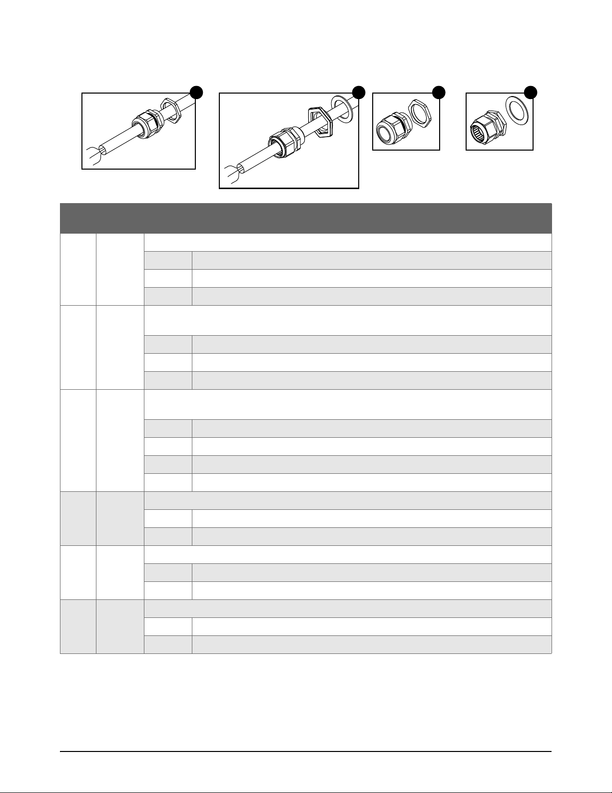
Power cord and strain relief
5
6
7
8
Service Parts
Item
Part
number
5 228885 Kit: Powermax105 SYNC power cord with strain relief, CSA models, 3 m (10 foot)
5 228886 Kit: Powermax105 SYNC power cord with strain relief, 230 V – 400 V CE models, 3 m
6 428949 Kit: Powermax105 SYNC power cord with strain relief, 380 V CCC / 400 V CE models, 3 m
7 228915 Kit: Strain relief for Powermax105 SYNC power cords, CSA models
Description and kit contents
229443 Power cord assembly 105 A CSA
108697 Strain relief
10 467 5 Aluminum locknut
(10 foot)
229449 Power cord assembly 105 A, 230 V – 400 V CE
108691 Strain relief
10 467 5 Aluminum locknut
(10 foot)
429052 Power cord assembly 105 A, 380 V CCC / 400 V CE
108795 Strain relief
104629 Strain relief adapter
075819 Aluminum washer
108697 Strain relief
10 467 5 Aluminum locknut
7 228913 Kit: Strain relief for Powermax105 SYNC power cords, 230 V – 400 V CE models
10 8691 Strain relief
104675 Aluminum locknut
8 228914 Kit: Strain relief for Powermax105 SYNC power cords, 380 V CCC / 400 V CE models
108795 Strain relief
075819 Aluminum washer
Powermax105 SYNC Service Parts and Procedures 810450 17
Service Parts
2
9
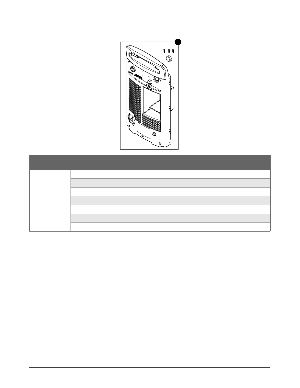
Rear panel
Item
Part
number
9 528006 Kit: Powermax105 SYNC plasma power supply rear panel with screws and CPC port cover
Description and kit contents
010586 Label: Protect earth
075807 Screw: M5 X 16, flat head (3)
101197 Plasma power supply rear panel
1088 67 CPC port c o v er
210008 Label: Power switch 105 A
CSA, CE, or CCC data plate for Powermax105 SYNC (preapplied)
For replacement procedures, refer to Replace the rear panel on page 56.
18 810450 Service Parts and Procedures Powermax105 SYNC
2
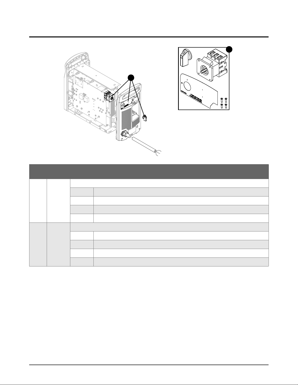
Plasma power supply interior, rear
1
1
Service Parts
Item
Part
number
1 228879 Kit: Powermax105 SYNC power switch CSA and CE 230 V – 400 V
1 228880 Kit: Powermax105SYNC power switch CE400V/CCC 380V
Description and kit contents
003206 Power switch
075760 Screw: #8 X 1/2, flat head (4)
10 885 8 Power switch handle
210008 Label: Power switch 105 A
005257 Power switch
075760 Screw: #8 X 1/2, flat head (4)
108858 Power switch handle
210008 Label: Power switch 105 A
For replacement procedures, refer to Replace the power switch on page 71.
Powermax105 SYNC Service Parts and Procedures 810450 19

Service Parts
2
1
4
2
3
5
4
6
1
4
2
3
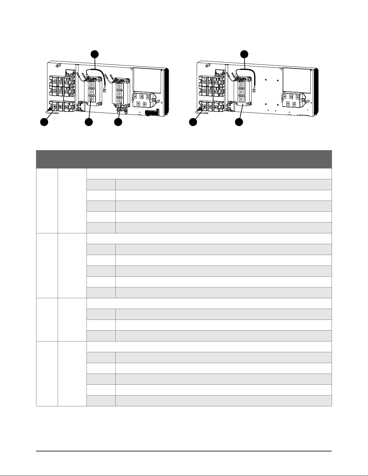
Plasma power supply interior, fan side
Item
1
Part
number
428942 Kit: Air filter assembly (includes air filter, air filter bowl, air filter element, and O-ring)
Description and kit contents
429017 Air filter assembly
104990 Tubing: 8 mm outer diameter X 1.75 inches
10 4487 Tubing: 8 mm outer diameter X 3.3 inches (optional – not shown)
20 810450 Service Parts and Procedures Powermax105 SYNC

Service Parts
2
Item
2
3
4
Part
number
Description and kit contents
528053 Kit: Solenoid valve (includes gas tubes and screws)
429061 Solenoid valve
101508 Bracket
104488 Tubing: 5/16 inch outer diameter X 7.75 inches
104632 Tubing: 5/16 inch outer diameter X 12 inches
104990 Tubing: 8 mm outer diameter X 1.75 inches
075711 Screw: M4 X 12, pan head
528017 Kit: 90° gas tube fitting
015921 90° gas tube fitting
528065 Kit: Powermax65/85/105 SYNC Gas tubes
104487 Tubing: 8 mm outer diameter X 3.3 inches (optional – not shown)
104488 Tubing: 5/16 inch outer diameter X 7.75 inches
104632 Tubing: 5/16 inch outer diameter X 12 inches
104990 Tubing: 8 mm outer diameter X 1.75 inches
For replacement procedures, refer to the following:
Replace the air filter assembly on page 79
Replace the solenoid valve on page 84
Replace the 90° gas tube fitting on page 88
Replace the gas tubes on page 87
Powermax105 SYNC Service Parts and Procedures 810450 21
Service Parts
2
5
6
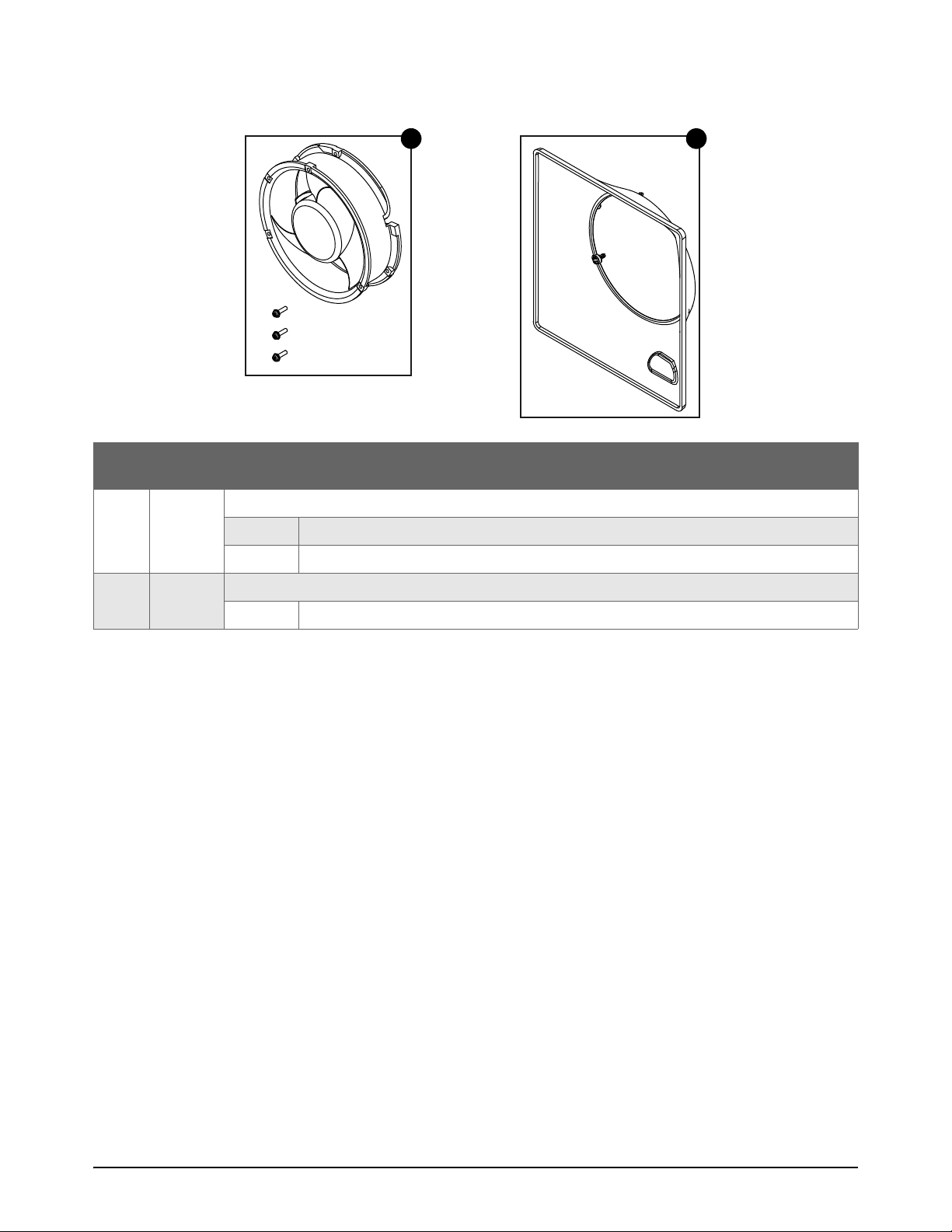
Fan and fan shroud
Item
5 428992 Kit: Powermax105 SYNC Fan assembly
6 228910 Kit: Powermax105 SYNC Fan shroud
Part
number
Description and kit contents
429072 Fan assembly
075650 Screw: M4 X 0.7 X 16-9, pan head (3)
101199 Fan shroud
For replacement procedures, refer to Replace the fan and fan shroud on page 81.
22 810450 Service Parts and Procedures Powermax105 SYNC

2
Plasma power supply interior, front
3
1
1
4
2
3
5
2
4
Service Parts
Item
1 528026 Kit: Control PCB and adjustment knob
2 428068 Kit: Ribbon cable for control PCB, 14 cm (5.5 inches)
3 228912 Kit: Powermax105 SYNC work lead receptacle
4 528025 Kit: Powermax105 SYNC torch quick-disconnect receptacle
Part
number
Description and kit contents
141472 Control PCB
108797 Adjustment knob
075418 Screw: #4 X 1/4, pan head (3)
223024 Ribbon cable that connects the control PCB to the DSP PCB
228800 Work lead receptacle
229885 Torch quick-disconnect receptacle housing
015920 Torch quick-disconnect receptacle
075899 Retention nut
075693 Screw: #6 X 1/2, pan head(4)
10 8076 Grommet
For replacement procedures, refer to the following:
Replace the control PCB and the ribbon cable on page 92
Replace the work lead receptacle on page 65
Replace the torch quick-disconnect receptacle on page 67
Powermax105 SYNC Service Parts and Procedures 810450 23

Service Parts
2
5
Front panel
Item
5 528005 Kit: Powermax105 SYNC plasma power supply front panel with screws
Part
number
Description and kit contents
002540 Gasket: LCD 65 A/85 A
075807 Screw: M5 X 16, flat head (2)
1010 6 3 Panel: Lens 65 A/85 A/105 A/125 A
101459 Panel: Plasma power supply front
210570 Label: Display panel 105 A
210596 Label: Hypertherm logo
For replacement procedures, refer to Replace the front panel on page 55.
24 810450 Service Parts and Procedures Powermax105 SYNC

2
Plasma power supply interior, power PCB side
1
2
3
4
5
2
Service Parts
Item
1 228895 Kit: Powermax105 SYNC component barrier
2 528033 Kit: Powermax105 SYNC power PCB CSA
2 528034 Kit: Powermax105 SYNC power PCB CE 230 V – 400 V
2 528035 Kit: Powermax105 SYNC power PCB CE 400 V / CCC 380 V
Part
number
Description and kit contents
075534 Screw: #6 X 5/16, pan head (4)
141458 Power PCB 105 A CSA
075534 Screw: #6 X 5/16, pan head (4)
141409 Power PCB 105 A CE 230 V – 400 V
075534 Screw: #6 X 5/16, pan head (4)
141460 Power PCB 105 A CE 400 V / CCC 380 V
For replacement procedures, refer to the following:
Replace the plasma power supply cover and component barrier on page 45
Replace the power PCB on page 94
Powermax105 SYNC Service Parts and Procedures 810450 25

Service Parts
2
3
4
5
Capacitors and DSP PCB
Item
3 428066 Kit: Power PCB capacitor
4 528028 Kit: DSP PCB
5 228888 Kit: Powermax105 SYNC bulk capacitors CSA and CE 230 V – 400 V
5 228889 Kit: Powermax105 SYNC bulk capacitors CE 400 V / CCC 380 V
Part
number
Description and kit contents
075569 Screw: M6 X 14-12.5, pan head (2)
075570 Screw: M5 X 14-12, pan head (2)
10 993 0 Capacitor: 3uF, 850 VDC
075766 Screw: M3 X 16, pan head (2)
108855 2-pin jumper (preinstalled on PCB)
141421 DSP PCB
210775 Label: “Save system data before you install this part” (not shown)
075567 Screw: M6 X 16-12.5, pan head (4)
209016 Capacitor: 3300uF, 500 VDC (2)
075567 Screw: M6 X 16-12, pan head (4)
209017 Capacitor: 5200uF, 400 VDC (2)
For replacement procedures, refer to the following:
Replace the power PCB capacitors on page 115
Replace the DSP PCB on page 91
Replace the bulk capacitors on page 117
26 810450 Service Parts and Procedures Powermax105 SYNC

2
Plasma power supply interior, heatsink
105A 400V CE/380V CCC105A CSA/230V–400V CE
1
2
1
2
You can purchase thermal grease separately.
Part number Description
128836 Thermal grease, 0.125 ounce
For replacement procedures, refer to How to clean the heatsink and apply thermal grease to the
heatsink components on page 114.
105 A heatsink diode bridges
Service Parts
Item
Part
number
1 228902 Kit: Powermax105 SYNC output diode bridge
2 528048 Kit: Powermax105 SYNC input diode bridge
Description and kit contents
209027 Output diode bridge (2)
075569 Screw: M6 X 14-12.5, pan head (6)
075851 M6 X 18.5±0.5-12.5, pan head (4)
128836 Thermal grease, 0.125 ounce
209174 Input diode bridge
075567 Screw: M6 X 16-12.5, pan head (2)
For replacement procedures, refer to the following:
Replace the output diode bridge on page 103
Replace the input diode bridge on page 105
Powermax105 SYNC Service Parts and Procedures 810450 27
Service Parts
2
105A 400V CE/380V CCC105A CSA/230V–400V CE
6
4
3
4
3
5 5
105 A heatsink IGBTs and thermal sensor
Item
Part
number
3 528044 Kit: Powermax105 SYNC pilot arc IGBT
4 528046 Kit: Powermax105 SYNC inverter IGBT
5 428990 Kit: Thermal sensor (switch)
Description and kit contents
109319 Pilot arc IGBT
223739 Pilot arc cable
075570 Screw: M5 X 14-12, pan head (2)
075851 Screw: M6 X 18.5±0.5-12.5, pan head (2)
128836 Thermal grease, 0.125 ounce
209445 Pilot arc IGBT
223738 PFC IGBT cable (2)
075569 Screw: M6 X 14-12.5, pan head (3)
075851 Screw: M6 X 18.5±0.5 12.5, pan head (4)
128836 Thermal grease, 0.125 ounce
209569 Transducer
075524 Screw: M5 X 16, pan head
075851 Screw: M6 X 18.5±0.5 12.5, pan head
6 528047 Kit: Powermax105 SYNC PFC IGBT, CSA and CE 230 V – 400 V
10 9802 PFC IGBT
223738 PFC IGBT cable (2)
28 810450 Service Parts and Procedures Powermax105 SYNC
075567 Screw: M6 X 16-12.5, pan head (4)
075569 Screw: M6 X 14-12.5, pan head (3)
128836 Thermal grease, 0.125 ounce

2
For replacement procedures, refer to the following:
Replace the pilot arc IGBT on page 106
Replace the inverter IGBT and the thermal sensor on page 108
Replace the PFC IGBT on page 110
IGBT tester
You can purchase the IGBT tester separately for troubleshooting.
Part number Description
128883 IGBT tester
Service Parts
Powermax105 SYNC Service Parts and Procedures 810450 29

Service Parts
2
105A 400V CE/380V CCC105A CSA/230V–400V CE
7
8
9
7
1
0
1
0
105 A heatsink resistors
Item
Part
number
7 228898 Kit: Powermax105 SYNC snubber resistor, 15 , 200 W
8 228693 Kit: Snubber resistor, 5 , 120 W, CSA and CE 230 V – 400 V
9 228894 Kit: Damper resistor, CSA and CE 230 V – 400 V
10 228897 Kit: Powermax105 SYNC snubber resistor, 5 , 200 W
Description and kit contents
209045 Snubber resistor, 15 , 200 W
108868 Standoff (2)
075526 Screw: M4 X 10, pan head (2)
128836 Thermal grease, 0.125 ounce
109799 Snubber resistor, 5 , 120 W
108868 Standoff (2)
075526 Screw: M4 X 10, pan head (2)
128836 Thermal grease, 0.125 ounce
229458 Damper resistor
075529 Screw: M3 X 10, pan head (2)
128836 Thermal grease, 0.125 ounce
209044 Snubber resistor, 5 , 200W
108868 Standoff (2)
075526 Screw: M4 X 10, pan head (2)
128836 Thermal grease, 0.125 ounce
For replacement procedures, refer to Replace the snubber resistors and the damper resistor on
page 112.
30 810450 Service Parts and Procedures Powermax105 SYNC

2
Power supply interior, magnetics
1
2 3
Service Parts
Item
Part
number
1 228873 Kit: Powermax105 SYNC PFC inductor CSA and CE 230 V – 400 V
1 228874 Kit: Powermax105 SYNC PFC inductor CE 400 V / CCC 380 V
2 228871 Kit: Powermax105 SYNC transformer CSA and CE 230 V – 400 V
2 228872 Kit: Powermax105 SYNC transformer CE 400 V / CCC 380 V
3 528038 Kit: Powermax105 SYNC output inductor
Description and kit contents
014353 Inductor: PFC
075569 Screw: M6 X 14-12.5, pan head (2)
014357 Inductor: PFC
075569 Screw: M6 X 14-12.5, pan head (2)
014354 Transformer
075569 Screw: M6 X 14-12.5, pan head (2)
014358 Transformer
075569 Screw: M6 X 14-12.5, pan head (2)
014441 Out put inductor
075569 Screw: M6 X 14-12.5, pan head (2)
For replacement procedures, refer to the following:
Replace the PFC inductor on page 130
Replace the transformer on page 126
Replace the output inductor on page 123
Powermax105 SYNC Service Parts and Procedures 810450 31

Service Parts
2
2
3
4
1
Machine interface and RS-485 serial interface upgrade kits
Item Part number Description
1 228539 Kit: Serial interface receptacle with internal cables and RS-485 serial interface PCB
2 528045 Kit: Machine interface receptacle with internal cables and voltage divider PCB for
Powermax105 SYNC (does not include cover for receptacle)
3 128650 Remote start pendant for machine torch, 7.6 m (25 foot)
3 128651 Remote start pendant for machine torch, 15 m (50 foot)
3 128652 Remote start pendant for machine torch, 23 m (75 foot)
3 428755 Remote start pendant for machine torch, 46 m (150 foot)
428975 Kit: Replacement switch for remote start pendant (not shown)
4 127204 Cover for machine interface receptacle
The remote start pendant connects to the machine interface receptacle.
EDGE®Connect CNC: To connect Hypertherm’s EDGE Connect CNC
with a Powermax65/85/105 SYNC, refer to the EDGE Connect
Installation and Setup Manual (809340).
EDGE®Pro CNC: To connect Hypertherm’s EDGE Pro CNC with a
Powermax65/85/105 SYNC, refer to the Phoenix Software V9 Series
Installation and Setup Manual (806410).
Technical documentation is available at www.hypertherm.com/docs.
32 810450 Service Parts and Procedures Powermax105 SYNC

Service Parts
2
1
2
3
4
External cables for machine interface receptacle and RS-485 serial interface receptacle
Hypertherm offers a variety of external cables that connect to the machine interface receptacle and
the RS-485 serial interface receptacle. For setup information refer to the
Powermax65/85/105 SYNC Mechanized Cutting Guide (810480).
Machine interface cables
Item Part number Description
1 023206 External machine interface cable*, 4 spade connectors, 7.6 m (25 foot)
1 023279 External machine interface cable*, 4 spade connectors, 15 m (50 foot)
2 228350 Kit: External machine interface cable
2 228351 Kit: External machine interface cable
3 223354 External machine interface cable
3 223355 External machine interface cable
3 223048 External machine interface cable
3 223356 External machine interface cable
3 123896 External machine interface cable
4 223733 External machine interface cable
ratio (for example, PlasmaCAM
4 223734 External machine interface cable
ratio (for example, PlasmaCAM
* Communicates start, stop, and arc transfer signals. Uses an external voltage divider PCB.
** Communicates start, stop, arc transfer, and divided arc voltage signals. Uses the internal voltage divider PCB.
†
Communicates start, stop, and divided arc voltage signals. Uses the internal voltage divider PCB.
**, 6 spade connectors, 7.6 m (25 foot)
**, 6 spade connectors, 15 m (50 foot)
**, D-sub connector with screws, 3.0 m (10 foot)
**, D-sub connector with screws, 6.0 m (20 foot)
**, D-sub connector with screws, 7.6 m (25 foot)
**, D-sub connector with screws, 10.7 m (35 foot)
**, D-sub connector with screws, 15 m (50 foot)
†
for mechanized cutting systems with a 21.1:1 voltage
®
systems), 6-pin DIN connector, 4.6 m (15 foot)
†
for mechanized cutting systems with a 21.1:1 voltage
®
systems), 6-pin DIN connector, 6.0 m (20 foot)
Powermax105 SYNC Service Parts and Procedures 810450 33

Service Parts
2
1
2
RS-485 serial interface cables
The RS-485 serial interface cables communicate information for controlling operating mode,
amperage, and gas pressure and control mode.
Item Part number Description
1 223236 External RS-485 cable, unterminated, 7.6 m (25 foot)
1 223237 External RS-485 cable, unterminated, 15 m (50 foot)
2 223239 External RS-485 cable, 9-pin D-sub connector for Hypertherm controls, 7.6 m (25 foot)
2 223240 External RS-485 cable, 9-pin D-sub connector for Hypertherm controls, 15 m (50 foot)
34 810450 Service Parts and Procedures Powermax105 SYNC
2
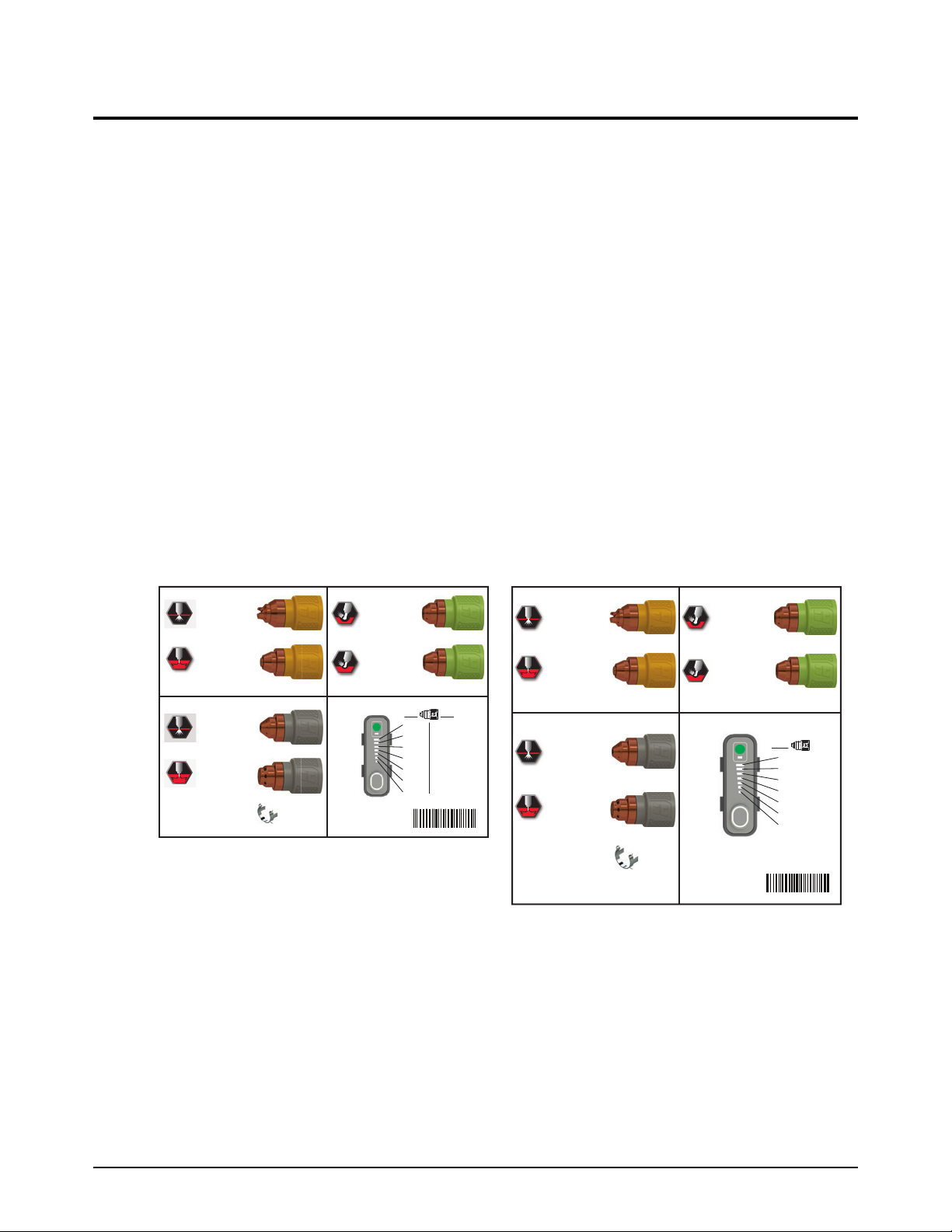
Powermax65/85/105 SYNC labels
FineCut
FineCut
30 A – 45 A: 428928
105 A: 428937
85 A: 428935
65 A: 428931
45 A: 428927
105 A: 428936
85 A: 428934
65 A: 428930
45 A: 428925
30 A – 45 A: 428926
105 A: 428938
45 A – 85 A: 428932
105 A: 428939
45 A – 85 A: 428933
428895
210692
105 A
95 A
85 A
65 A
55 A
45 A
30 A
105 A
FineCut
®
FineCut
®
30 A – 45 A: 428928
85 A: 428935
65 A: 428931
45 A: 428927
85 A: 428934
65 A: 428930
45 A: 428925
30 A – 45 A: 428926
45 A – 85 A: 428932
45 A – 85 A: 428933
428895
210691
65 A
60 A
55 A
45 A
35 A
25 A
20 A
65 A
85 A
75 A
65 A
55 A
45 A
35 A
25 A
85 A
Powermax65/85 SYNC
Powermax105 SYNC
Part number Description
528018 Kit: Powermax65 SYNC labels, CSA
528020 Kit: Powermax85 SYNC labels, CSA
528022 Kit: Powermax105 SYNC labels, CSA
528019 Kit: Powermax65 SYNC labels, CE/CCC
528021 Kit: Powermax85 SYNC labels, CE/CCC
528023 Kit: Powermax105 SYNC labels, CE/CCC
The label kits include:
Warning label
Interface decals for the front panel and rear panel
Product decals
Cartridge label
Service Parts
Cartridge labels
Powermax105 SYNC Service Parts and Procedures 810450 35

Service Parts
2
WARNING: This product can expose you to chemicals including
lead and lead compounds, which are known to the State of
California to cause cancer and birth defects or other reproductive
harm. For more information go to www.p65warnings.ca.gov.
AVERTISSEMENT : Ce produit peut vous exposer à des produits chimiques, dont
le plomb et des composés de plomb, reconnus par l’État de la Californie comme cause
de cancer et d’anomalie congénitale ou d’autres anomalies de l’appareil reproducteur.
Pour obtenir de plus amples renseignements, consultez le www.p65warnings.ca.gov.
Read and follow these instructions, employer safety
practices, and material safety data sheets. Refer to
ANS Z49.1, “Safety in Welding, Cutting and Allied
Processes” from American Welding Society
(http://www.aws.org) and OSHA Safety and Health
Standards, 29 CFR 1910 (http://www.osha.gov).
WARNING
1. Cutting sparks can cause explosion or fire.
1.1 Do not cut near flammables.
1.2 Have a fire extinguisher nearby and ready to use.
1.3 Do not use a drum or other closed container as a cutting
table.
2. Plasma arc can injure and burn; point the nozzle
away from yourself. Arc starts instantly when
triggered.
2.1 Turn off power before disassembling torch.
2.2 Do not grip the workpiece near the cutting path.
2.3 Wear complete body protection.
3. Hazardous voltage. Risk of electric shock or burn.
3.1 Wear insulating gloves. Replace gloves when wet or
damaged.
3.2 Protect from shock by insulating yourself from work and
ground.
3.3 Disconnect power before servicing. Do not touch live parts.
4. Plasma fumes can be hazardous.
4.1 Do not inhale fumes.
4.2 Use forced ventilation or local exhaust to remove the fumes.
4.3 Do not operate in closed spaces. Remove fumes with
ventilation.
6. Become trained. Only qualified personnel should
operate this equipment. Use torches specified in the manual.
Keep non-qualified personnel and children away.
5. Arc rays can burn eyes and injure skin.
5.1 Wear correct and appropriate protective equipment to
protect head, eyes, ears, hands, and body. Button shirt
collar. Protect ears from noise. Use welding helmet with
the correct shade of filter.
7. Do not remove, destroy, or cover this label.
Replace if it is missing, damaged, or worn.
Plasma cutting can be injurious to operator and persons in the
work area. Consult manual before operating. Failure to follow
all these safety instructions can result in death.
AVERTISSEMENT
Le coupage plasma peut être préjudiciable pour l’opérateur
et les personnes qui se trouvent sur les lieux de travail.
Consulter le manuel avant de faire fonctionner. Le non respect
des ces instructions de sécurité peut entraîner la mort.
1. Les étincelles de coupage peuvent provoquer
une explosion ou un incendie.
1.1 Ne pas couper près des matières inflammables.
1.2 Un extincteur doit être à proximité et prêt à être utilisé.
1.3 Ne pas utiliser un fût ou un autre contenant fermé comme
table de coupage.
2. L’arc plasma peut blesser et brûler; éloigner
la buse de soi. Il s’allume instantanément
quand on l’amorce.
2.1 Couper l’alimentation avant de démonter la torche.
2.2 Ne pas saisir la pièce à couper de la trajectoire de coupage.
2.3 Se protéger entièrement le corps.
3. Tension dangereuse. Risque de choc électrique
ou de brûlure.
3.1 Porter des gants isolants. Remplacer les gants quand ils sont
humides ou endommagés.
3.2 Se protéger contre les chocs en s’isolant de la pièce et de
la terre.
3.3 Couper l’alimentation avant l’entretien. Ne pas toucher
les pièces sous tension.
4. Les fumées plasma peuvent être dangereuses.
4.1 Ne pas inhaler les fumées.
4.2 Utiliser une ventilation forcée ou un extracteur local pour
dissiper les fumées.
4.3 Ne pas couper dans des espaces clos. Chasser les fumées
par ventilation.
5. Les rayons d’arc peuvent brûler les yeux et
blesser la peau.
5.1 Porter un bon équipement de protection pour se protéger
la tête, les yeux, les oreilles, les mains et le corps. Boutonner
le col de la chemise. Protéger les oreilles contre le bruit. Utiliser
un masque de soudeur avec un filtre de nuance appropriée.
6. Suivre une formation. Seul le personnel qualifié a
le droit de faire fonctionner cet équipement. Utiliser
exclusivement les torches indiquées dans le manual. Le
personnel non qualifié et les enfants doivent se tenir à l’écart.
7. Ne pas enlever, détruire ni couvrir cette étiquette.
La remplacer si elle est absente, endommagée ou usée.
(
110673 Rev F)
CSA warning label
This warning label is affixed to some plasma power supplies. It is important that the operator and
maintenance technician understand the intent of these warning symbols as described.
36 810450 Service Parts and Procedures Powermax105 SYNC

Service Parts
2
www.hypertherm.com/weeewww.hypertherm.com/weee
Descriptions of warning label icons
This warning label is affixed to some plasma power supplies. It is important
that the operator and maintenance technician understand the intent of
these warning symbols as described. The descriptions at right are
numbered the same as the symbols on the label.
1. Cutting sparks can cause
explosion or fire.
1.1 Do not cut near flammables.
1.2 Have a fire extinguisher nearby
and ready to use.
1.3 Do not use a drum or other
closed container as a cutting
table.
2. Plasma arc can injure and burn;
point the nozzle away from
yourself. Arc starts instantly when
triggered.
2.1 Turn off electrical power before
disassembling torch.
2.2 Do not grip the workpiece near
the cutting path.
2.3 Wear complete body protection.
3. Hazardous voltage. Risk of
electric shock or burn.
3.1 Wear insulating gloves. Replace
gloves when wet or damaged.
3.2 Protect from shock by insulating
yourself from work and ground.
3.3 Disconnect power before
servicing. Do not touch live parts.
4. Plasma fumes can be hazardous.
4.1 Do not inhale fumes.
4.2 Use forced ventilation or local
exhaust to remove fumes.
4.3 Do not operate in closed spaces.
Remove fumes with ventilation.
5. Arc rays can burn eyes and injure
skin.
5.1 Wear correct and approved
protective equipment to protect
head, eyes, ears, hands, and
body. Button shirt collar. Protect
ears from noise. Use welding
helmet with the correct shade of
filter.
6. Become trained. Only qualified
personnel should operate this
equipment. Use torches specified
in the manual. Keep non-qualified
personnel and children away.
7. Do not remove, destroy, or cover
this label. Replace it if it is
missing, damaged, or worn.
Powermax105 SYNC Service Parts and Procedures 810450 37

Service Parts
2
Parts necessary for safety
Genuine Hypertherm parts are factory-recommended parts for your Hypertherm system. Any
damage caused by the use of parts that are not from Hypertherm may not be covered by the
Hypertherm warranty. Parts that are necessary for safety are parts that must be replaced with only
genuine Hypertherm parts to maintain the warranty and system certifications.
Part number Description Page
228885 Kit: Powermax105 SYNC power cord with strain relief, CSA models, 3 m (10 foot) page 17
228886 Kit: Powermax105 SYNC power cord with strain relief, 230 V – 400 V CE models,
3 m (10 foot)
228913 Kit: Strain relief for Powermax105 SYNC power cords, 230 V – 400 V CE models page 17
228914 Kit: Strain relief for Powermax105 SYNC power cords, 380 V CCC / 400 V CE
models
228915 Kit: Strain relief for Powermax105 SYNC power cords, CSA models page 17
428949 Kit: Powermax105 SYNC power cord with strain relief, 380 V CCC / 400 V CE
models, 3m (10foot)
228879 Kit: Powermax105 SYNC power switch CSA and CE 230 V – 400 V page 19
228880 Kit: Powermax105SYNC power switch CE400V/CCC 380V page 19
428992 Kit: Powermax105 SYNC Fan assembly page 22
528033 Kit: Powermax105 SYNC power PCB CSA page 25
528034 Kit: Powermax105 SYNC power PCB CE 230 V – 400 V page 25
528035 Kit: Powermax105 SYNC power PCB CE 400 V / CCC 380 V page 25
528028 Kit: DSP PCB page 26
228888 Kit: Powermax105 SYNC bulk capacitors CSA and CE 230 V – 400 V page 26
228889 Kit: Powermax105 SYNC bulk capacitors CE 400 V / CCC 380 V page 26
228873 Kit: Powermax105 SYNC PFC inductor CSA and CE 230 V – 400 V page 31
page 17
page 17
page 17
228874 Kit: Powermax105 SYNC PFC inductor CE 400 V / CCC 380 V page 31
228871 Kit: Powermax105 SYNC transformer CSA and CE 230 V – 400 V page 31
228872 Kit: Powermax105 SYNC transformer CE 400 V / CCC 380 V page 31
528038 Kit: Powermax105 SYNC output inductor page 31
38 810450 Service Parts and Procedures Powermax105 SYNC

Service Parts
2
Recommended spare parts
Hypertherm recommends that service centers keep the following spare parts available for repairs
because these parts are parts necessary for safety or are usually exposed to continuous wear. Parts
that are necessary for safety are parts that must be replaced with only genuine Hypertherm parts to
maintain the warranty and system certifications. You may need to revise or expand this list for your
customers, based on the conditions and work environments in your region.
Part number Description Page
428141 Kit: Replacement screws (16) for plasma power supply cover page 14
428143 Kit: Adjustment knob only page 14
223254 105 A work lead with hand clamp, 7.6 m (25 foot) page 15
223284 105 A work lead with ring terminal, 7.6 m (25 foot) page 15
228695 Kit: Air filter element and O-ring (compatible with both filter bowl types) page 16
428352 Kit: Air filter bowl, polycarbonate (comes with plasma power supply, includes the
O-ring but not the filter element)
027055 Silicone lubricant, 0.25 ounces page 16
228879 Kit: Powermax105 SYNC power switch CSA and CE 230 V – 400 V page 19
228880 Kit: Powermax105SYNC power switch CE400V/CCC 380V page19
428942 Kit: Air filter assembly (includes air filter, air filter bowl, air filter element, and
O-ring)
528017 Kit: 90° gas tube fitting page 21
528053 Kit: Solenoid valve (includes gas tubes and screws) page 21
528065 Kit: Powermax65/85/105 SYNC Gas tubes page 21
228910 Kit: Powermax105 SYNC Fan shroud page 22
428992 Kit: Powermax105 SYNC Fan assembly page 22
528026 Kit: Control PCB and adjustment knob page 23
428068 Kit: Ribbon cable for control PCB, 14 cm (5.5 inches) page 23
528033 Kit: Powermax105 SYNC power PCB CSA page 25
528034 Kit: Powermax105 SYNC power PCB CE 230 V – 400 V page 25
528035 Kit: Powermax105 SYNC power PCB CE 400 V / CCC 380 V page 25
page 16
page 20
228888 Kit: Powermax105 SYNC bulk capacitors CSA and CE 230 V – 400 V page 26
228889 Kit: Powermax105 SYNC bulk capacitors CE 400 V / CCC 380 V page 26
128836 Thermal grease, 0.125 ounce page 27
228873 Kit: Powermax105 SYNC PFC inductor CSA and CE 230 V – 400 V page 31
228874 Kit: Powermax105 SYNC PFC inductor CE 400 V / CCC 380 V page 31
228871 Kit: Powermax105 SYNC transformer CSA and CE 230 V – 400 V page 31
228872 Kit: Powermax105 SYNC transformer CE 400 V / CCC 380 V page 31
528038 Kit: Powermax105 SYNC output inductor page 31
Powermax105 SYNC Service Parts and Procedures 810450 39

Service Parts
2
Find replacement parts by part number
Use this list to find the page number for a part number in Service Parts on page 13.
Part number .................................................................................................... Page
008337............................................................................................................15
023206............................................................................................................33
023279............................................................................................................33
027055............................................................................................................16
123896............................................................................................................33
127204............................................................................................................32
128650............................................................................................................32
128651............................................................................................................32
128652............................................................................................................32
128836............................................................................................................27
128883............................................................................................................29
223048............................................................................................................33
223236............................................................................................................34
223237............................................................................................................34
223239............................................................................................................34
223240............................................................................................................34
223254............................................................................................................15
223255............................................................................................................15
223284............................................................................................................15
223285............................................................................................................15
223294............................................................................................................15
223297............................................................................................................15
223298............................................................................................................15
223299............................................................................................................15
223300............................................................................................................15
223354............................................................................................................33
223355............................................................................................................33
223356............................................................................................................33
223733............................................................................................................33
223734............................................................................................................33
228350............................................................................................................33
228351............................................................................................................33
228539............................................................................................................32
228693............................................................................................................30
228695............................................................................................................16
228871............................................................................................................31
228872............................................................................................................31
40 810450 Service Parts and Procedures Powermax105 SYNC

2
228873............................................................................................................31
228874............................................................................................................31
228879............................................................................................................19
228880............................................................................................................19
228885............................................................................................................17
228886............................................................................................................17
228888............................................................................................................26
228889............................................................................................................26
228891............................................................................................................15
228894............................................................................................................30
228895............................................................................................................25
228897............................................................................................................30
228898............................................................................................................30
228902............................................................................................................27
228910............................................................................................................22
228912............................................................................................................23
228913............................................................................................................17
228914............................................................................................................17
228915............................................................................................................17
428066............................................................................................................26
428068............................................................................................................23
428141............................................................................................................14
428143............................................................................................................14
428352............................................................................................................16
428415............................................................................................................16
428685............................................................................................................16
428755............................................................................................................32
428942............................................................................................................20
428949............................................................................................................17
428975............................................................................................................32
428990............................................................................................................28
428992............................................................................................................22
528005............................................................................................................24
528006............................................................................................................18
528013............................................................................................................14
528014............................................................................................................14
528017............................................................................................................21
528018............................................................................................................35
528019............................................................................................................35
528020............................................................................................................35
528021............................................................................................................35
528022............................................................................................................35
Service Parts
Powermax105 SYNC Service Parts and Procedures 810450 41

Service Parts
2
528023............................................................................................................35
528025............................................................................................................23
528026............................................................................................................23
528028............................................................................................................26
528033............................................................................................................25
528034............................................................................................................25
528035............................................................................................................25
528038............................................................................................................31
528044............................................................................................................28
528045............................................................................................................32
528046............................................................................................................28
528047............................................................................................................28
528048............................................................................................................27
528053............................................................................................................21
528065............................................................................................................21
42 810450 Service Parts and Procedures Powermax105 SYNC

Service Procedures for the Cover, Panels,
and Connectors
WARNING
ELECTRIC SHOCK CAN KILL
Disconnect electric power before doing installation or maintenance. You can
get a serious electric shock if electric power is not disconnected. Electric
shock can seriously injure or kill you.
All work that requires removal of the plasma power supply outer cover or
panels must be done by a qualified technician.
Refer to the Safety and Compliance Manual (80669C) for more safety
information.
NOTICE
Static electricity can cause damage to printed circuit boards (PCBs). Use correct
precautions when you touch PCBs.
Keep PCBs in antistatic containers.
Put on a grounded wrist strap when you touch PCBs.
Powermax105 SYNC Service Parts and Procedures 810450 43

Service Procedures for the Cover, Panels, and Connectors
3
Tools necessary for this section
Assorted Phillips
Assorted Phillips
Adjustable wrench
Grounded wrist strap (or similar grounding accessory)
®
, TORX®, and blade screwdrivers
®
offset screwdrivers
More tools necessary for some procedures
Cable ties are necessary for Replace the rear panel on page 56.
Cable cutters are necessary for Replace the work lead connector on page 63.
44 810450 Service Parts and Procedures Powermax105 SYNC
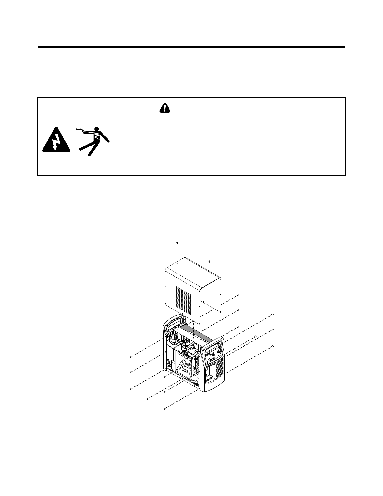
Service Procedures for the Cover, Panels, and Connectors
3
Replace the plasma power supply cover and component barrier
For kit contents, refer to Plasma power supply interior, power PCB side on page 25.
Remove the plasma power supply cover and component barrier
WARNING
STORED ENERGY HAZARD
You can get a serious electric shock from the uncontrolled release of stored
energy in capacitors. Electric shock can seriously injure or kill you.
Before you remove the plasma power supply cover, disconnect electrical
input power and wait 1 minute to allow stored energy to discharge.
1. Set the power switch on the plasma power supply to OFF (O), disconnect the power cord, and
disconnect the gas supply.
2. Remove the 16 screws from the plasma power supply cover.
3. Remove the plasma power supply cover.
Powermax105 SYNC Service Parts and Procedures 810450 45

Service Procedures for the Cover, Panels, and Connectors
3
4. Remove the component barrier from the power-PCB side of the plasma power supply.
46 810450 Service Parts and Procedures Powermax105 SYNC

Service Procedures for the Cover, Panels, and Connectors
3
1
2
1
2
Install the component barrier and plasma power supply cover
WARNING
SHOCK HAZARD
You can get a serious electric shock if you touch exposed plasma power
supply components. Electric shock can seriously injure or kill you.
You must install the component barrier and the plasma power supply cover.
Never operate the plasma power supply unless the component barrier and the
plasma power supply cover are in position.
1. Push in the sides of the
component barrier so that the
component barrier bends out
slightly down the center.
2. Put the sides of the component
barrier inside the plasma power
supply frame .
Powermax105 SYNC Service Parts and Procedures 810450 47
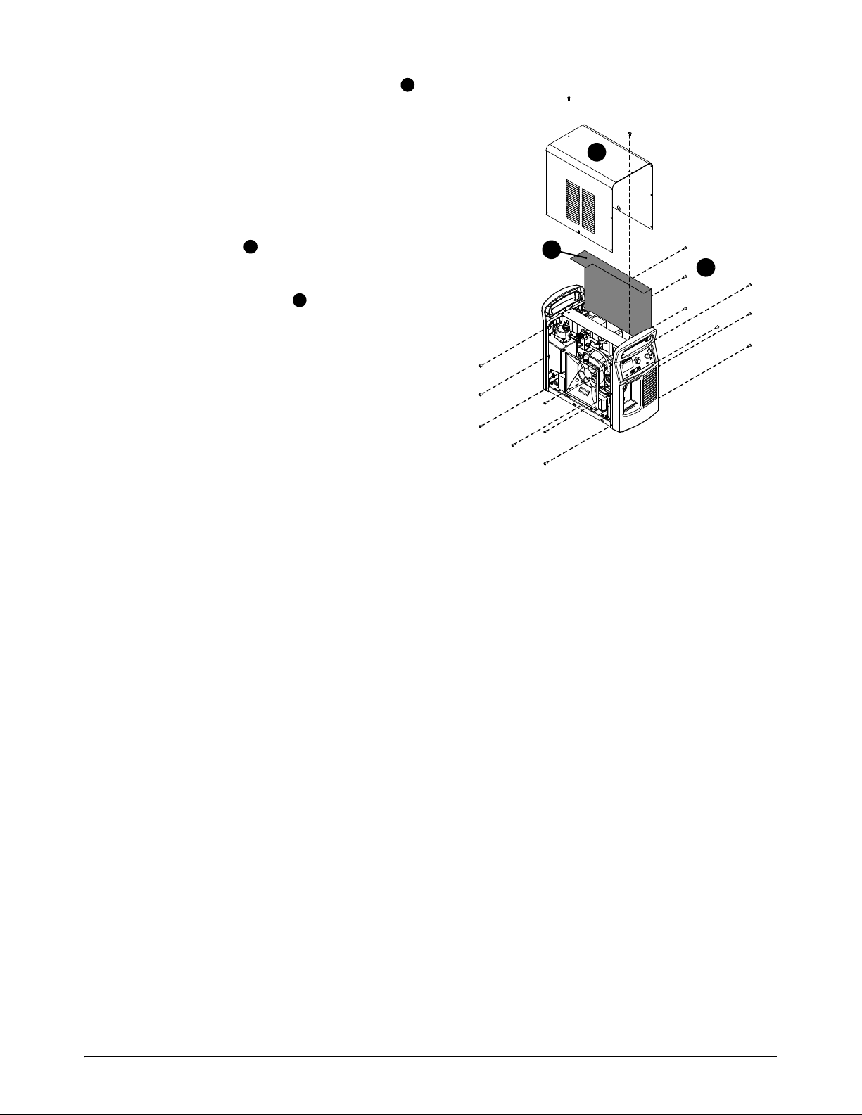
Service Procedures for the Cover, Panels, and Connectors
3
3
4
5
3
4
5
3. Fold the top of the component barrier onto
the top edge of the power PCB, inside the
plasma power supply frame and under the
end panel bracket.
4. Make sure that all of the wires that are
connected to the power PCB are behind the
component barrier.
5. Put the cover on the plasma power supply.
Do not pinch any wires.
6. Install the 16 screws on the plasma power
supply cover. Tighten the screws to 1.7 N·m
(15 lbf·in).
48 810450 Service Parts and Procedures Powermax105 SYNC

3
Replace the end panel bracket
Remove the end panel bracket
1. Set the power switch on the plasma power supply to OFF (O), disconnect the power cord, and
disconnect the gas supply.
2. Remove the plasma power supply cover and the component barrier. Refer to page 45.
3. Remove the 2 screws from the end panel bracket.
Service Procedures for the Cover, Panels, and Connectors
4. Lift the end panel bracket off of the plasma power supply.
Powermax105 SYNC Service Parts and Procedures 810450 49

Service Procedures for the Cover, Panels, and Connectors
3
Install the end panel bracket
1. Put the end panel bracket on the top of the plasma power supply.
2. Install the 2 screws for the end panel bracket.
3. Install the plasma power supply cover and the component barrier. Refer to page 47.
50 810450 Service Parts and Procedures Powermax105 SYNC

3
Loosen and attach the front panel
Loosen the front panel
Some repairs are easier to make if you first loosen the front panel from the plasma power supply. To
replace an old front panel with a new one, complete this procedure, then continue with step 3 in
Replace the front panel on page 55.
1. Set the power switch on the plasma power supply to OFF (O), disconnect the power cord, and
disconnect the gas supply.
2. Remove the plasma power supply cover and the component barrier. Refer to page 45.
3. Remove the end panel bracket. Refer to page 49.
4. Remove the left mounting screw from the DSP PCB.
5. Disconnect the ribbon cable from the DSP PCB.
Service Procedures for the Cover, Panels, and Connectors
6. Put the fan side of the plasma power supply on a clean, dry, and flat surface.
7. Remove the screws that attach the front panel to the bottom of the
plasma power supply.
8. Move the bottom of the front panel off of the bottom of the plasma
power supply. Use a blade screwdriver to carefully pry the front panel
away from the bottom of the plasma power supply.
9. Put the plasma power supply in an upright position.
Powermax105 SYNC Service Parts and Procedures 810450 51

Service Procedures for the Cover, Panels, and Connectors
3
Attach the front panel
1. Put the fan side of the plasma power supply on a clean, dry, and flat surface.
2. Push the front panel onto the bottom of the plasma power supply.
3. Install the screws that attach the front panel to the bottom of the
plasma power supply. Tighten the screws to 2.3 N·m (20 lbf·in).
4. Put the plasma power supply upright position.
5. Connect the ribbon cable to J6 on the DSP PCB.
6. Install the left mounting screw in the DSP PCB. Tighten the screw to
1.1N·m (10lbf·in).
7. Install the end panel bracket. Refer to page 50.
52 810450 Service Parts and Procedures Powermax105 SYNC
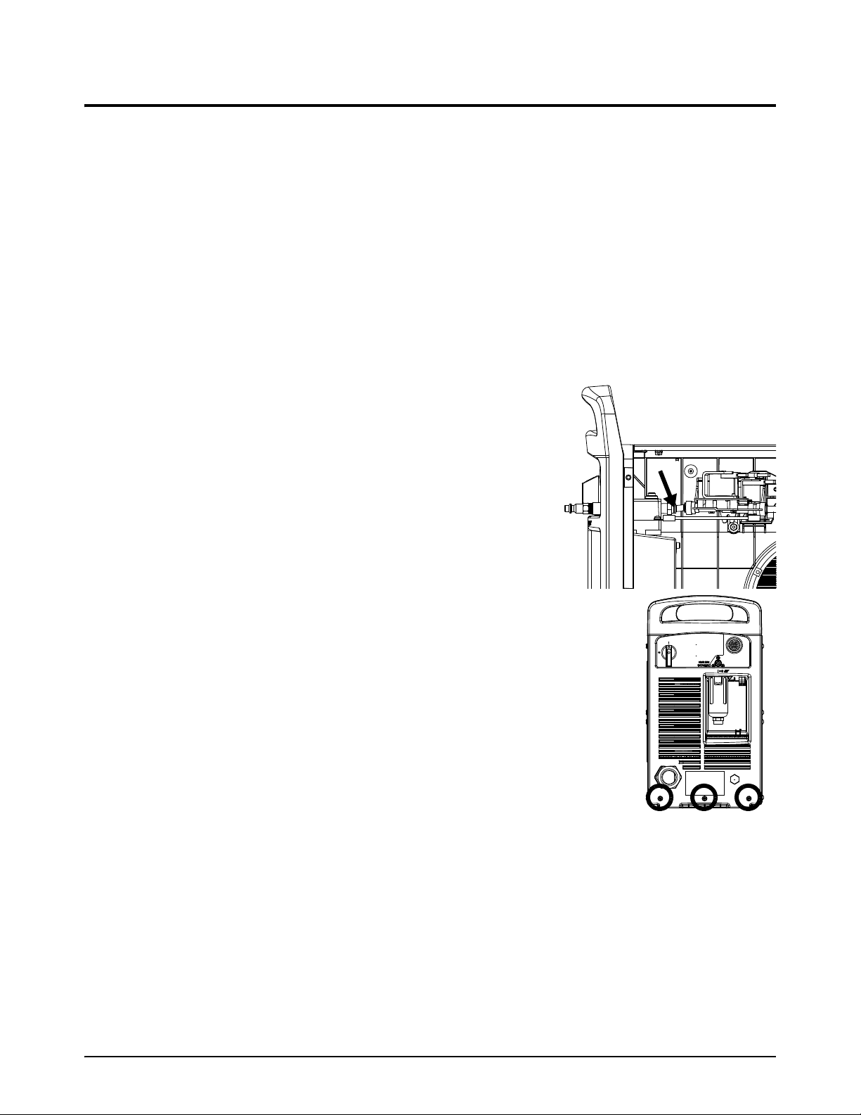
3
Loosen and attach the rear panel
Loosen the rear panel
Some repairs are easier to make if you first loosen the rear panel from the plasma power supply. To
replace an old rear panel with a new one, complete this procedure, then continue with step 3 in
Replace the rear panel on page 56.
1. Set the power switch on the plasma power supply to OFF (O), disconnect the power cord, and
disconnect the gas supply.
2. Remove the plasma power supply cover and the component barrier. Refer to page 45.
3. Remove the end panel bracket. Refer to page 49.
4. Push-to-disconnect the gas tube from the air filter.
5. Put the fan side of the plasma power supply on a clean,
dry, and flat surface.
Service Procedures for the Cover, Panels, and Connectors
6. Remove the screws that attach the rear panel to the
bottom of the plasma power supply.
7. Move the bottom of the rear panel off of the bottom of the plasma power
supply. Use a blade screwdriver to carefully pry the rear panel away from
the bottom of the plasma power supply.
8. Put the plasma power supply in an upright position.
Powermax105 SYNC Service Parts and Procedures 810450 53

Service Procedures for the Cover, Panels, and Connectors
3
Attach the rear panel of the plasma power supply
1. Put the fan side of the plasma power supply on a clean, dry, and flat surface.
2. Push the rear panel onto the bottom of the plasma power supply.
3. Install the screws that attach the rear panel to the bottom of the plasma
power supply. Tighten the screws to 2.3 N·m (20 lbf·in).
4. Put the plasma power supply in an upright position.
5. Push-to-connect the gas tube to the air filter.
6. Install the end panel bracket. Refer to page 50.
54 810450 Service Parts and Procedures Powermax105 SYNC
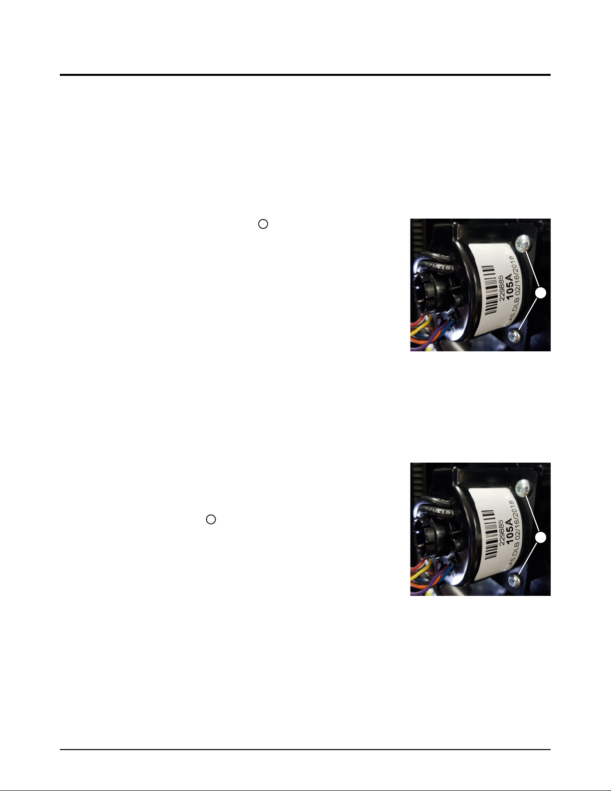
3
Replace the front panel
111
1
For kit contents, refer to Front panel on page 24.
Remove the front panel
1. Set the plasma power supply switch to OFF (O), disconnect the power cord from the power
source, and disconnect the gas supply.
2. Loosen the front panel. Refer to page 51.
3. Remove the 4 mounting screws from the torch
quick-disconnect receptacle housing.
4. Remove the torch quick-disconnect receptacle housing from the
front panel.
5. Remove the work lead receptacle. Refer to page 65.
Service Procedures for the Cover, Panels, and Connectors
6. Remove the control PCB and disconnect the ribbon cable.
Refer to page 92.
7. Remove the front panel from the plasma power supply.
Install the front panel
1. Push the front panel onto the body of the plasma power supply.
2. Install the control PCB and ribbon cable. Refer to page 93.
3. Install the work lead receptacle. Refer to page 66.
4. Attach the torch quick-disconnect receptacle to the inside of
the front panel with the 4 mounting screws. Tighten the screws
to 1.7N·m (15lbf·in) .
5. Attach the front panel. Refer to page 52.
6. Install the plasma power supply cover and the component
barrier. Refer to page 47.
Powermax105 SYNC Service Parts and Procedures 810450 55

Service Procedures for the Cover, Panels, and Connectors
3
Replace the rear panel
For kit contents, refer to Rear panel on page 18.
Remove the rear panel
1. Set the plasma power supply switch to OFF (O), disconnect the power cord from the power
source, and disconnect the gas supply.
2. Loosen the rear panel. Refer to page 53.
3. Remove the air filter assembly and gas inlet fitting. Refer to page 79.
4. If a machine interface receptacle is installed, remove the 2 screws from the machine interface
receptacle.
5. If an RS-485 serial interface receptacle is installed, do the following:
a. Remove the RS-485 serial interface cable connector from J1 on the RS-485 PCB.
b. Cut the cable tie that holds the cable.
56 810450 Service Parts and Procedures Powermax105 SYNC

Service Procedures for the Cover, Panels, and Connectors
3
c. Remove the 2 mounting screws from the RS-485 serial interface receptacle.
d. Remove the RS-485 serial interface receptacle and cable from the rear panel.
6. Remove the power switch. Refer to page 71.
7. Remove the power cord:
For the procedure to replace the power cord and strain relief, refer to the
Power Cord and Strain Relief Replacement Field Service Bulletin
(810420). Download the file at www.hypertherm.com/docs.
a. Remove the screw that attaches the ground wire to the heatsink.
b. On the outside of the plasma power supply, remove the strain relief retention nut from the
strain relief. Move the retention nut away from the plasma power supply.
c. Remove the power cord.
CSA: From the outside of the plasma power supply, pull the power cord and power
wires through the strain relief in the rear panel.
CCC/CE: From the inside of the plasma power supply, pull the power wires and the
power cord through the strain relief in the rear panel.
CCC/CE models have ferrite cores on the power wires and the ground
wire. To maintain CCC/CE certification, install a CCC/CE power cord.
8. Remove the rear panel from the plasma power supply.
Powermax105 SYNC Service Parts and Procedures 810450 57

Service Procedures for the Cover, Panels, and Connectors
3
4
1
2
3
1
3
123
4
9. Remove the strain relief from the rear panel:
a. On the inside of the plasma power supply, remove the nut . For some models, also remove
the washer.
b. On the outside of the plasma power supply, remove the strain relief . For some models,
also remove the strain relief adapter .
58 810450 Service Parts and Procedures Powermax105 SYNC

3
Install the rear panel
12345
CSA
CCC/CE
1
2
3
4
5
6
6
1. Install the strain relief into the new rear panel:
a. On the outside of the plasma power supply, put the strain relief in the hole in the rear panel
of the plasma power supply. If your model has a strain relief adapter, first put the strain relief
in the adapter.
b. On the inside of the plasma power supply, install the nut on the strain relief. If your model
has a washer, first put the washer on the strain relief. Tighten the nut with your hand.
2. Put the power cord in the strain relief:
CSA: From the outside of the plasma power supply, put the power wires and ground wire
through the retention nut . Then put the power wires and ground wire through the strain
relief .
CCC/CE: From the inside of the plasma power supply, put the wires at the line-disconnect
end of the power cord through the strain relief . From the outside of the plasma power
supply, pull the power cord through the strain relief. Then put the wires at the
line-disconnect end of the power cord through the retention nut .
Service Procedures for the Cover, Panels, and Connectors
CCC/CE models have ferrite cores on the power wires and the
ground wire. To maintain CCC/CE certification, install a CCC/CE power
cord.
3. Attach the ground wire to the heatsink with the screw you removed previously. Tighten the
screw to 4 N·m (35 lbf·in).
Powermax105 SYNC Service Parts and Procedures 810450 59
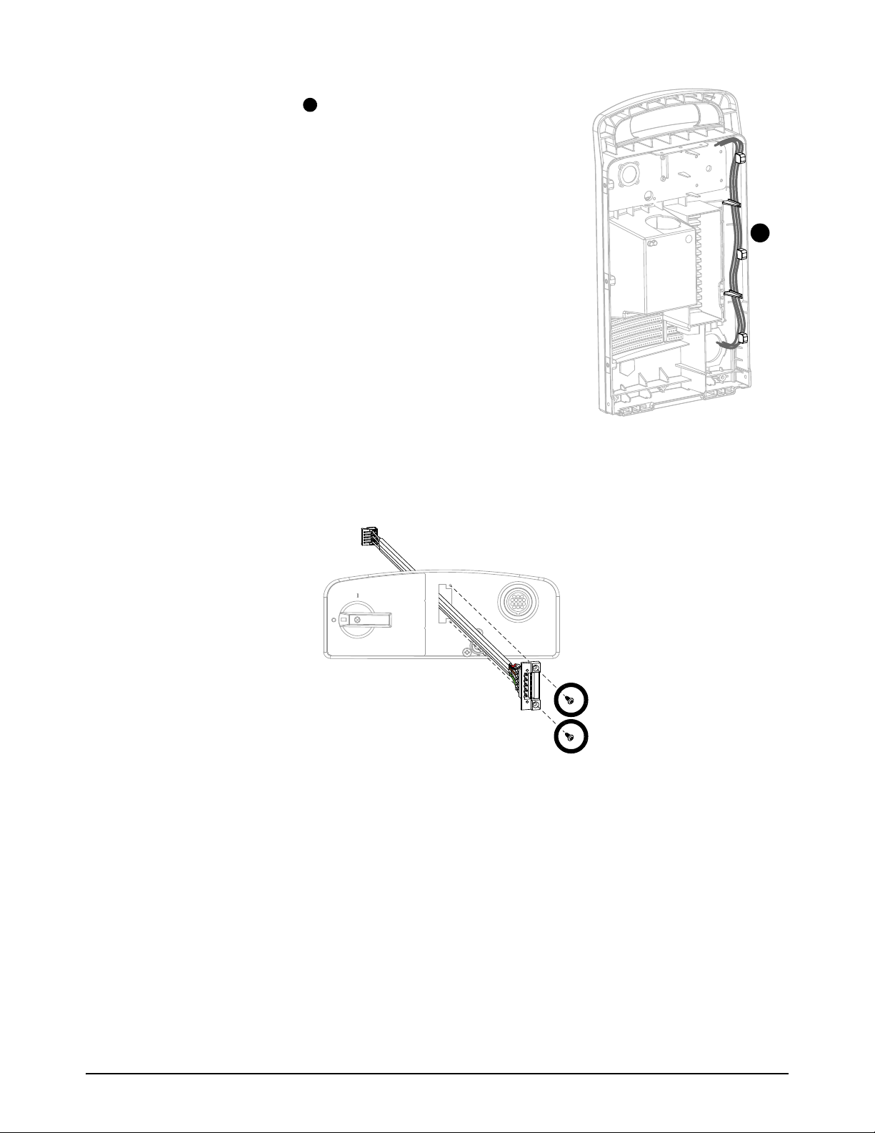
Service Procedures for the Cover, Panels, and Connectors
3
7
7
4. Push the 3 power wires into the inside edge of the rear panel
using the guide posts . Make sure that the routing of the
wires is correct.
5. From the outside of the rear panel, tighten the strain relief
retention nut on the strain relief with your hand plus a quarter
turn with a wrench.
6. Put fan side of the plasma power supply on a clean, dry, and flat
surface.
7. Push the rear panel onto the body of the plasma power supply.
8. Put the plasma power supply in an upright position.
9. Install the power switch. Refer to page 72.
10. If you have an RS-485 serial interface receptacle, do the
following:
a. Put the RS-485 serial interface cable through the hole in
the rear panel.
b. Attach the RS-485 serial interface receptacle to the rear panel with the 2 mounting screws.
Tighten the screws to 0.8 N·m (7 lbf·in).
60 810450 Service Parts and Procedures Powermax105 SYNC

Service Procedures for the Cover, Panels, and Connectors
3
8
8
c. Put the RS-485 serial interface cable behind the gas tubes and below the solenoid valve.
NNOTICE
Do not put the RS-485 serial interface cable below the fan. This can cause the wires to be pinched by
the fan. If any wires get pinched by the fan, this can damage the wires and prevent the fan from
operating correctly.
d. Bundle the RS-485 serial interface cable with the cables that are already in the plasma
power supply with a new cable tie.
e. Put the RS-485 serial interface cable connector through the upper grommet on the
center panel.
f. Connect the RS-485 serial interface cable connector to J1 on the RS-485 PCB.
Powermax105 SYNC Service Parts and Procedures 810450 61

Service Procedures for the Cover, Panels, and Connectors
3
11 . If you have a machine interface receptacle, install the 2 mounting screws that attach the
machine interface receptacle to the rear panel. Tighten the screws to 1.1 Nm (10 lbfin).
12. Install the air filter assembly and gas inlet fitting. Refer to page 80.
13. Attach the rear panel. Refer to page 54.
14. Install the plasma power supply cover and the component barrier. Refer to page 47.
62 810450 Service Parts and Procedures Powermax105 SYNC

3
Replace the work lead connector
1
2
1
2
1
2
1
2
For kit contents, refer to Work leads on page 15.
Remove the work lead connector
1. Set the plasma power supply switch to OFF (O), disconnect the power cord from the power
source, and disconnect the gas supply.
2. Use cable cutters to cut the work lead cable close to the rubber boot .
Install the work lead connector
1. Put the new rubber boot over the work lead cable.
Service Procedures for the Cover, Panels, and Connectors
2. Move the rubber boot back along the work lead cable.
3. Strip 13 mm (0.5 inches) off the end of the work lead cable.
4. Put the stripped end of the work lead cable into the new work lead connector.
5. Tighten the set screw to 11.3 Nm (100 lbfin).
Powermax105 SYNC Service Parts and Procedures 810450 63

Service Procedures for the Cover, Panels, and Connectors
3
3
4
3
4
5
6
5
6
6. Align the tabs in the rubber boot with the slots in the work lead connector.
CAUTION
INCORRECTLY INSTALLED WORK LEAD CONNECTORS CAN OVERHEAT
To prevent damage and risk of burns, make sure that the face of the work lead connector is
flush with the face of the rubber boot.
7. Align the face of the rubber boot with the face of the work lead connector. If the face of
the work lead connector is below the face of the rubber boot, the work lead can overheat which
can cause damage and risk of burns.
64 810450 Service Parts and Procedures Powermax105 SYNC

3
Replace the work lead receptacle
1
2
3
4
1
234
For kit contents, refer to Plasma power supply interior, front on page 23.
Remove the work lead receptacle
1. Set the plasma power supply switch to OFF (O),
disconnect the power cord from the power source, and
disconnect the gas supply.
2. Remove the plasma power supply cover and the
component barrier. Refer to page 45.
3. Remove the bolt from the work lead receptacle.
4. Remove the ring terminal from the work lead receptacle.
5. Remove the nut and washer from the work lead
receptacle.
Service Procedures for the Cover, Panels, and Connectors
6. Remove the work lead receptacle. Push the work lead
receptacle in the direction of the front panel.
Powermax105 SYNC Service Parts and Procedures 810450 65

Service Procedures for the Cover, Panels, and Connectors
3
1
2
1
2
6
5
4
3
3
4
5
6
Install the work lead receptacle
1. Push the new work lead receptacle into the hole in the
front panel. Position the receptacle so that the key way
points up.
2. From inside the plasma power supply, put the washer
on the work lead receptacle.
3. Install the nut onto the work lead receptacle. Tighten the
nut to 13.6 Nm (120 lbfin).
4. Put the ring terminal on the work lead receptacle.
5. Install the bolt on the work lead receptacle. Tighten the
bolt to 15.8 Nm (140 lbfin).
6. Install the plasma power supply cover and the component
barrier. Refer to page 47.
66 810450 Service Parts and Procedures Powermax105 SYNC

Service Procedures for the Cover, Panels, and Connectors
3
RED
ORG
RED
B
R
WORK
LEAD
TP7
TP9
TP8
W
R
B
1
2
1
2
3
4
3
4
Replace the torch quick-disconnect receptacle
For kit contents, refer to Plasma power supply interior, front on page 23.
Remove the torch quick-disconnect receptacle
1. Set the plasma power supply switch to OFF (O), disconnect the power cord from the power
source, and disconnect the gas supply.
2. Remove the plasma power supply cover and the component barrier. Refer to page 45.
3. Loosen the front panel. Refer to page 51.
4. Remove the torch interface cable connector from
J17 on the power PCB.
5. From the fan side, pull the torch interface cable
through the grommet.
6. Remove the nozzle wires from the power PCB.
7. Pull the wires through the protective sheath .
Powermax105 SYNC Service Parts and Procedures 810450 67

Service Procedures for the Cover, Panels, and Connectors
3
5
5
6
7
8
6
7
8
9
10
9
10
8. Push-to-disconnect the 90° gas inlet fitting from the torch
quick-disconnect receptacle.
9. Remove the following components from the torch
quick-disconnect receptacle:
Retention nut
Ring terminal
Washer
10. Push the torch quick-disconnect receptacle out
through the torch quick-disconnect receptacle housing.
11 . Remove the 4 screws from the torch quick-disconnect
receptacle housing.
12. Remove the torch quick-disconnect receptacle housing from
the front panel.
68 810450 Service Parts and Procedures Powermax105 SYNC

3
Install the torch quick-disconnect receptacle
1
1
2
3
2
3
6
5
4
4
5
6
7
7
8
9
8
9
1. Use the 4 new screws to install the new torch
quick-disconnect receptacle into the front panel. Tighten the
screws to 1.7 Nm (15 lbfin).
2. From the front panel, put the small end of the new torch
quick-disconnect receptacle into the center hole of the receptacle
housing. Align the hexagonal flats on the receptacle with the hexagonal
flats on the receptacle housing.
3. Push the receptacle in until the front is flush with the plastic
receptacle housing .
Service Procedures for the Cover, Panels, and Connectors
4. Push the washer onto the hub of the torch
quick-disconnect receptacle until the washer makes a
click.
5. Put the ring terminal on the torch quick-disconnect
receptacle.
6. Put the new retention nut onto the torch
quick-disconnect receptacle. Tighten the retention nut to
14.7 Nm (130 lbfin).
7. Push-to-connect the 90° gas inlet fitting .
8. Put the nozzle wires through the protective sheath in
the center panel.
Powermax105 SYNC Service Parts and Procedures 810450 69

Service Procedures for the Cover, Panels, and Connectors
3
1
0
1
0
RED
ORG
RED
B
R
WORK
LEAD
TP9
TP8
W
B
1
2
1
1
1
1
1
2
9. Put the torch interface cable through the upper grommet on the center panel.
10. From the power PCB side, attach the nozzle wires
to the power PCB. Tighten the screw to 2.3 Nm
(20 lbfin).
11 . Connect the torch interface cable connector from
J17 on the power PCB.
12. Attach the front panel. Refer to page 52.
13. Install the plasma power supply cover and the
component barrier. Refer to page 47.
70 810450 Service Parts and Procedures Powermax105 SYNC

3
Replace the power switch
1
2
3
123
6 BAR (85 PSI) MIN
9 BAR (135 PSI) MAX
4
6
6
5
456
For kit contents, refer to Plasma power supply interior, rear on page 19.
Remove the power switch
1. Set the plasma power supply switch to OFF (O), disconnect the
power cord from the power source, and disconnect the gas
supply.
2. Loosen the rear panel. Refer to page 53.
3. Use an offset Phillips screwdriver to loosen the set screws that
attach the 3 power wires to the top of the power switch.
4. Pull the 3 power wires from the power switch.
5. Make a note of which AC input wires are attached to T1, T2, and
T3.
Service Procedures for the Cover, Panels, and Connectors
6. Use an offset Phillips screwdriver to loosen the set screws that attach the 3 AC input wires
to the bottom of the power switch.
7. Pull the 3 power wires from the power switch.
8. Loosen the set screws on the auxiliary switch.
9. Pull the 2 wires from the auxiliary switch.
10. Remove the power switch handle screw .
11 . Pull the power switch handle straight off the post.
12. Use a blade screwdriver to pry up the edge of the
label .
13. Peel off the label.
14. Remove the 4 power switch mounting screws .
15. Remove the power switch from the plasma power supply.
Powermax105 SYNC Service Parts and Procedures 810450 71
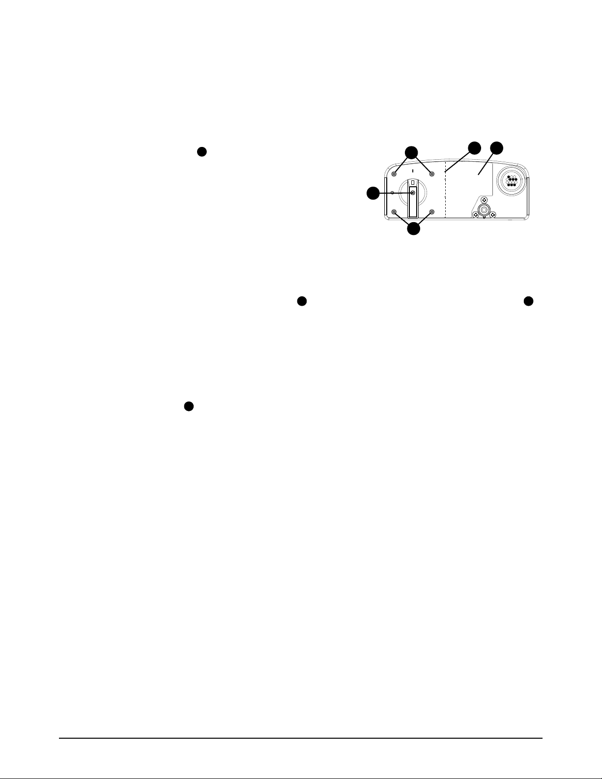
Service Procedures for the Cover, Panels, and Connectors
3
6 BAR (85 PSI) MIN
9 BAR (135 PSI) MAX
4
1
1
2 3
123
4
Install the power switch
1. Put the power switch into the plasma power supply.
2. Push the power switch post through the hole in the rear panel.
3. Attach the power switch to the rear panel with the
4 mounting screws . Tighten the screws to 1.7 Nm
(15 lbfin).
4. If the optional RS-485 receptacle is not installed:
a. Peel the protective cover off the new label.
b. Carefully align the hole in the label with the correct
hole in the rear panel.
c. Push the label onto the rear panel.
5. If the optional RS-485 receptacle is installed:
a. Bend the new label at the perforation and tear the label in half. Discard the right half .
b. Peel the protective cover off the left half of the new label.
c. Carefully align the hole in the label with the correct hole in the rear panel.
d. Push the label onto the rear panel.
6. Put the power switch handle onto the post.
7. Install the screw into the power switch handle. Tighten the screw to 0.8 Nm (7 lbfin).
72 810450 Service Parts and Procedures Powermax105 SYNC

Service Procedures for the Cover, Panels, and Connectors
3
7
6
5
5
6
7
8. Put the auxiliary wires in the auxiliary switch. Tighten the
screws to 1.1 Nm (10 lbfin).
9. Put the AC input wires into the bottom of the power switch.
Tighten the set screws to 2.3 Nm (20 lbfin).
10. Put the 3 power wires into the top of the power switch. Tighten
the set screws to 2.3 Nm (20 lbfin).
Table 1
Color
Power Wire Position CSA CE/CCC
L1 Black Brown
L2 White Black
L3 Red Grey
11 . Attach the rear panel. Refer to page 54.
12. Install the plasma power supply cover and the component barrier. Refer to page 47.
Powermax105 SYNC Service Parts and Procedures 810450 73

Service Procedures for the Cover, Panels, and Connectors
3
74 810450 Service Parts and Procedures Powermax105 SYNC

Service Procedures for the Gas Line
WARNING
ELECTRIC SHOCK CAN KILL
Disconnect electric power before doing installation or maintenance. You can
get a serious electric shock if electric power is not disconnected. Electric
shock can seriously injure or kill you.
All work that requires removal of the plasma power supply outer cover or
panels must be done by a qualified technician.
Refer to the Safety and Compliance Manual (80669C) for more safety
information.
NOTICE
Static electricity can cause damage to printed circuit boards (PCBs). Use correct
precautions when you touch PCBs.
Keep PCBs in antistatic containers.
Put on a grounded wrist strap when you touch PCBs.
Powermax105 SYNC Service Parts and Procedures 810450 75

Service Procedures for the Gas Line
4
Tools necessary for this section
Assorted Phillips
Assorted TORX
Adjustable wrench
Grounded wrist strap (or similar grounding accessory)
®
, TORX®, and blade screwdrivers
®
offset screwdrivers
More tools necessary for some procedures
Cable ties are necessary for Replace the fan and fan shroud on page 81 and Replace the
solenoid valve on page 84.
76 810450 Service Parts and Procedures Powermax105 SYNC

4
Replace the air filter bowl and filter element
1
123
2
3
2
For kit contents, refer to Plasma power supply exterior, rear on page 16.
Remove the air filter bowl and filter element
1. Set the power switch on the plasma power
supply to OFF (O).
2. Disconnect the power cord from electrical
power.
3. Disconnect the gas supply from the rear of the
plasma power supply.
4. Hold the filter bowl with your right hand. With
the index finger of your left hand, push down
the latch and turn the filter bowl
approximately 45 degrees to the right.
Service Procedures for the Gas Line
5. Pull the filter bowl straight down to remove.
6. Gently turn and pull the filter element out of the filter bowl. Be careful not to damage the
O-ring at the top of the bowl.
Powermax105 SYNC Service Parts and Procedures 810450 77

Service Procedures for the Gas Line
4
1
1
2
2
Replace the air filter bowl, O-ring, and filter element
1. To replace the filter element, twist and pull the plastic fittings away from the filter element,
approximately a 1/4 turn. Set the fittings aside. Discard the used filter element.
2. Put the new air filter element in the plastic fittings. Twist the plastic fittings until they lock
together, approximately a 1/4 turn.
3. If the air filter bowl will not be replaced:
Clean the bowl and O-ring of any oil, dirt, or other contamination. Apply a thin layer of
silicone lubricant on the O-ring.
To replace the O-ring, discard the used O-ring. Put the thick O-ring at the top of the filter
bowl.
4. To replace the air filter bowl, discard the old air filter bowl.
5. Put the filter element inside the air filter bowl. Push down on the top plastic fitting until you hear
a click.
78 810450 Service Parts and Procedures Powermax105 SYNC

4
Install the air filter bowl and filter element
1
2
1
2
3
3
1. Vertically align the filter bowl and push it up into the
receptacle in the rear panel.
2. Turn the filter bowl 45 degrees to the left until you hear
a click.
Replace the air filter assembly
Service Procedures for the Gas Line
For kit contents, refer to Plasma power supply interior, fan side on page 20.
This kit contains an extra gas tube. This procedure uses the shortest gas tube in the kit.
Remove the air filter assembly
1. Set the plasma power supply switch to OFF (O), disconnect the power cord from the power
source, and disconnect the gas supply.
2. Remove the plasma power supply cover and the component barrier. Refer to page 45.
3. Loosen the rear panel. Refer to page 53.
4. Remove the air filter bowl and air filter element. Refer to
page 77.
5. Push-to-disconnect both ends of the gas tube .
6. From the outside of the rear panel, remove the gas
fitting from the air filter assembly.
7. Remove the 3 screws from the rear panel.
8. Remove the air filter assembly from the plasma power
supply.
Powermax105 SYNC Service Parts and Procedures 810450 79

Service Procedures for the Gas Line
4
1
1
3
2
4
2
3
4
Install the air filter assembly
1. Remove the new air filter bowl and air filter element from the new air filter assembly.
2. Put the new air filter assembly into the plasma power supply.
3. Install the 3 screws on the rear panel. Tighten the
screws to 1.7 Nm (15 lbf·in).
4. Apply a small amount of thread sealant to the threads of
the gas fitting.
Too much thread sealant can contaminate the gas
line.
NOTICE
PTFE TAPE CAN CAUSE CLOGGED VALVES, REGULATORS, AND TORCHES
Never use PTFE tape on any joint preparation. Use only a liquid or paste thread sealant on male thread
ends.
5. Install the gas fitting onto the air filter assembly.
CSA models: Tighten the 1/4 NPT quick-disconnect
nipple to 10.2 N·m (90 lbf·in).
CE/CCC models: Tighten the G-1/4 BSPP adapter to
12.4 N·m (110 lbf·in).
6. Use the shortest gas tube in the kit. Push-to-connect the
new gas tube into the new air filter assembly and
solenoid valve.
7. Attach the ground wires with the ground screw .
Tighten the screw to 2.8 Nm (25 lbfin).
8. Install the new air filter bowl and air filter element. Refer to page 79.
9. Attach the rear panel. Refer to page 54.
10. Install the component barrier and the plasma power supply cover. Refer to page 47.
80 810450 Service Parts and Procedures Powermax105 SYNC

4
Replace the fan and fan shroud
J1
J2
J5
J6
1
For kit contents, refer to Plasma power supply interior, fan side on page 20.
Remove the fan and fan shroud
1. Set the plasma power supply switch to OFF (O), disconnect the power cord from the power
source, and disconnect the gas supply.
2. Remove the plasma power supply cover and the component barrier. Refer to page 45.
3. Remove the end panel bracket. Refer to page 49.
4. Pull the fan shroud straight off of the fan.
5. Cut the cable tie that holds the fan wires.
6. Disconnect the fan wire connector from J1 near the top of the power PCB.
Service Procedures for the Gas Line
7. From the fan side, pull the fan wire through the grommet.
Powermax105 SYNC Service Parts and Procedures 810450 81

Service Procedures for the Gas Line
4
2
2
2
8. Use an offset TORX screwdriver to remove the 3 screws from the fan.
9. Remove the old fan.
82 810450 Service Parts and Procedures Powermax105 SYNC

4
Install the fan and fan shroud
1
1
1
2
J1
J2
J5
J6
2
1. Attach the new fan to the center panel with the 3 supplied screws .Tighten the screws to
2.2 Nm (20 lbfin).
Service Procedures for the Gas Line
2. Put the fan wire through the lower left grommet .
3. Connect the fan wire connector to J1 near the top of the power PCB.
4. Bundle the fan and solenoid valve wires with a new cable tie.
5. Align the plastic posts on the fan shroud with the related holes in the fan.
6. Push the fan shroud straight onto the fan.
7. Install the end panel bracket. Refer to page 50.
8. Install the component barrier and the plasma power supply cover. Refer to page 47.
Powermax105 SYNC Service Parts and Procedures 810450 83

Service Procedures for the Gas Line
4
J1
J2
J5
J6
1
2
1
3
3
4
5
2
Replace the solenoid valve
For kit contents, refer to Plasma power supply interior, fan side on page 20.
Remove the solenoid valve
1. Set the plasma power supply switch to OFF (O), disconnect the power cord from the power
source, and disconnect the gas supply.
2. Remove the plasma power supply cover and the component barrier. Refer to page 45.
3. Remove the end panel bracket. Refer to page 49.
4. Cut the cable tie that holds the solenoid valve wires.
5. Disconnect the solenoid valve wire connector from J6 near the top of the power PCB.
6. From the fan side, pull the solenoid valve wires through the grommet .
7. Remove the mounting screw from the bracket.
84 810450 Service Parts and Procedures Powermax105 SYNC

4
8. Push-to-disconnect the short gas tube and long gas tube from the solenoid valve .
3
4
5
123
4
5
3
3
1
2
4
5
9. Remove the solenoid valve and bracket.
10. Push-to-disconnect the short gas tube from the air filter assembly .
11 . Push-to-disconnect the long gas tube from elbow fitting .
Install the solenoid valve
1. Push-to-connect the shortest gas tube supplied into the air filter assembly .
2. Push-to-connect the longest gas tube supplied into the elbow fitting .
3. If necessary, snap the new bracket onto the new solenoid valve.
4. Hold the solenoid valve and bracket in position, and push-to-connect the short gas tube and
long gas tube to the solenoid valve .
Service Procedures for the Gas Line
5. Attach the new solenoid valve to the center panel with the supplied screw . Tighten the screw
to 2.2Nm (20lbfin).
6. Put the solenoid valve wires through the lower left grommet .
Powermax105 SYNC Service Parts and Procedures 810450 85
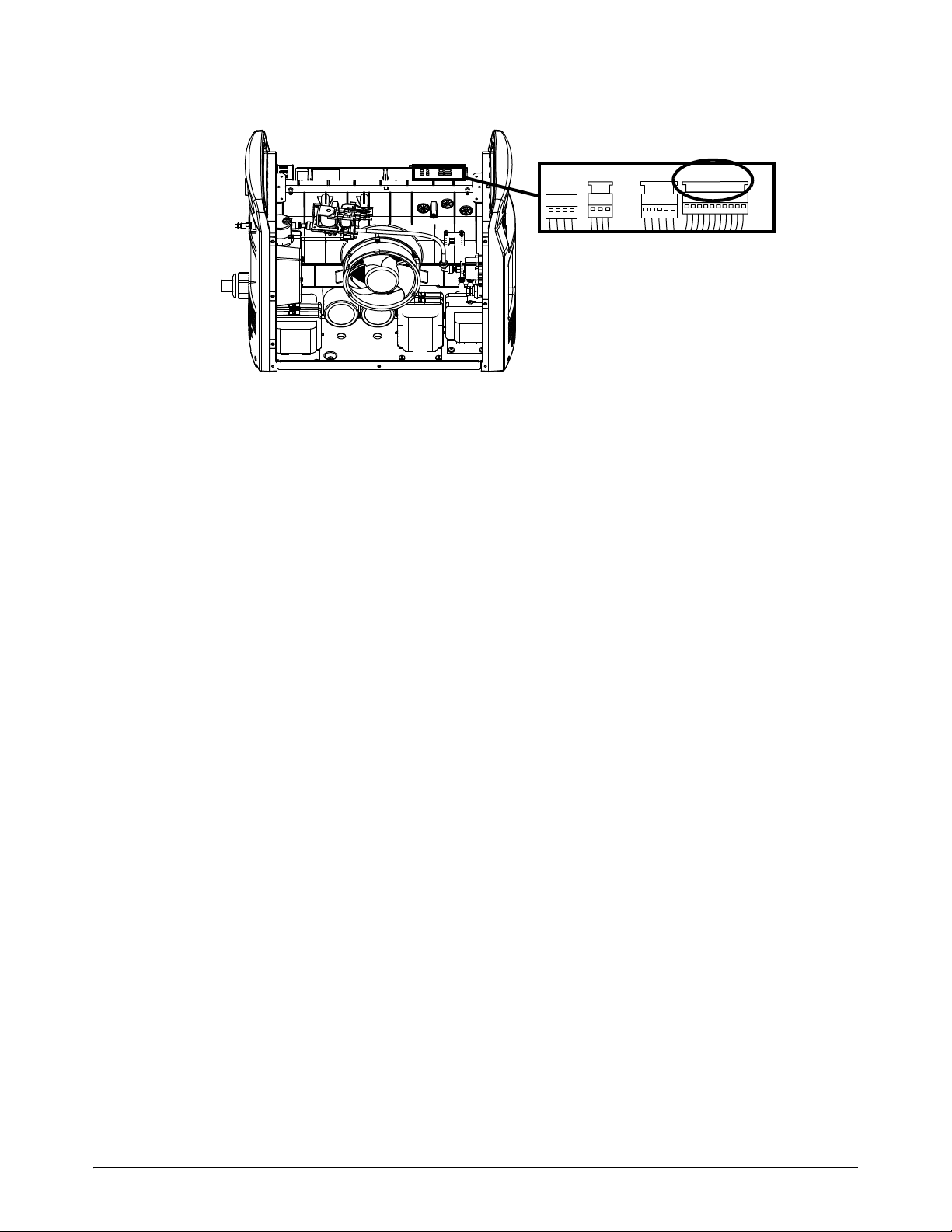
Service Procedures for the Gas Line
4
J1
J2
J5
J6
7. Connect the solenoid valve wire connector to J6 near the top of the power PCB.
8. Bundle the fan and solenoid valve wires with a new cable tie.
9. Install the end panel bracket. Refer to page 50.
10. Install the component barrier and the plasma power supply cover. Refer to page 47.
86 810450 Service Parts and Procedures Powermax105 SYNC

4
Replace the gas tubes
1
2
2
1
2
1
2
2
1
2
For kit contents, refer to Plasma power supply interior, fan side on page 20.
This kit contains an extra gas tube.
NOTICE
Do not make kinks or bend the gas tubes. This will damage the gas tubes.
Remove the gas tubes
1. Set the plasma power supply switch to OFF (O), disconnect the power cord from the power
source, and disconnect the gas supply.
2. Remove the plasma power supply cover and the component barrier. Refer to page 45.
Service Procedures for the Gas Line
3. Remove the end panel bracket. Refer to page 49.
4. Push-to-disconnect both ends of the short gas
tube .
5. Push-to-disconnect both ends of the long gas
tube .
Install the gas tubes
1. Use the 44.5 mm (1.75 inch) gas tube in the kit.
Push-to-connect both ends of the gas tube .
2. Use the 304.8 mm (12 inch) gas tube in the kit.
Push-to-connect both ends of the gas tube .
3. Install the end panel bracket. Refer to page 50.
4. Install the component barrier and the plasma power
supply cover. Refer to page 47.
Powermax105 SYNC Service Parts and Procedures 810450 87

Service Procedures for the Gas Line
4
1
2
1
2
Replace the 90° gas tube fitting
For kit contents, refer to Plasma power supply interior, fan side on page 20.
1. Set the plasma power supply switch to OFF (O), disconnect the power cord from the power
source, and disconnect the gas supply.
2. Remove the plasma power supply cover and the component barrier. Refer to page 45.
3. Push-to-disconnect the long gas tube from the 90° degree gas inlet fitting.
4. Push-to-disconnect the 90° gas inlet fitting from the torch quick-disconnect receptacle .
5. Push-to-connect the new 90° gas inlet fitting to the torch quick-disconnect receptacle.
6. Push-to-connect the long gas tube into the new 90° gas inlet fitting.
88 810450 Service Parts and Procedures Powermax105 SYNC
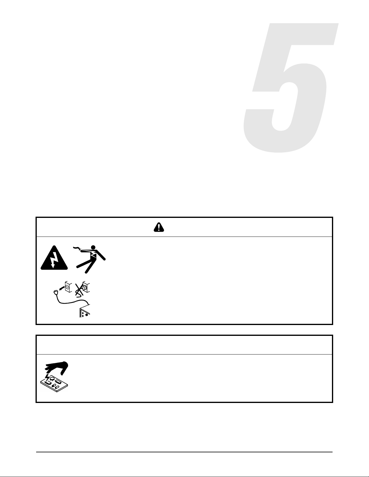
Service Procedures for the PCBs and
Related Components
WARNING
ELECTRIC SHOCK CAN KILL
Disconnect electrical power before doing installation or maintenance.
The line-disconnect switch must REMAIN in the OFF position until all
installation or maintenance steps are complete.
See the Safety and Compliance Manual (80669C) for more safety
information.
NOTICE
Static electricity can cause damage to printed circuit boards (PCBs). Use correct
precautions when you touch PCBs.
Keep PCBs in antistatic containers.
Put on a grounded wrist strap when you touch PCBs.
Powermax105 SYNC Service Parts and Procedures 810450 89

Service Procedures for the PCBs and Related Components
5
Tools necessary for this section
Assorted Phillips
Assorted offset screwdrivers
Assorted hexagonal socket wrenches
Needle nose pliers
Grounded wrist strap (or similar grounding accessory)
Anti-static container to store printed circuit boards (PCBs)
®
, TORX®, and blade screwdrivers
More tools necessary to for some procedures
The following tools are necessary for Replace the heatsink components on page 102:
Plastic scraper
Isopropyl alcohol
Paper towels
Lint-free cloth
90 810450 Service Parts and Procedures Powermax105 SYNC

Service Procedures for the PCBs and Related Components
5
Replace the DSP PCB
For kit contents, refer to Plasma power supply interior, front on page 23.
For the procedure to replace the DSP PCB, refer to the DSP PCB Replacement and Power Supply
Data Backup Field Service Bulletin (810950). Download the file at www.hypertherm.com/docs.
NOTICE
POSSIBLE LOSS OF DATA
You can lose system-level cut data if you do not save that data before you install the new DSP PCB.
Use the procedure in the 810950 Field Service Bulletin to save the system-level cut data from the old
DSP PCB to the new DSP PCB.
NOTICE
SYSTEM CANNOT CUT
The 2-pin jumper (108855) in this kit is necessary to save system data to the new DSP PCB. But it
prevents the torch from firing a plasma arc if you keep it on the DSP PCB.
Make sure that you remove the 2-pin jumper from the new DSP PCB before you try to cut.
Powermax105 SYNC Service Parts and Procedures 810450 91
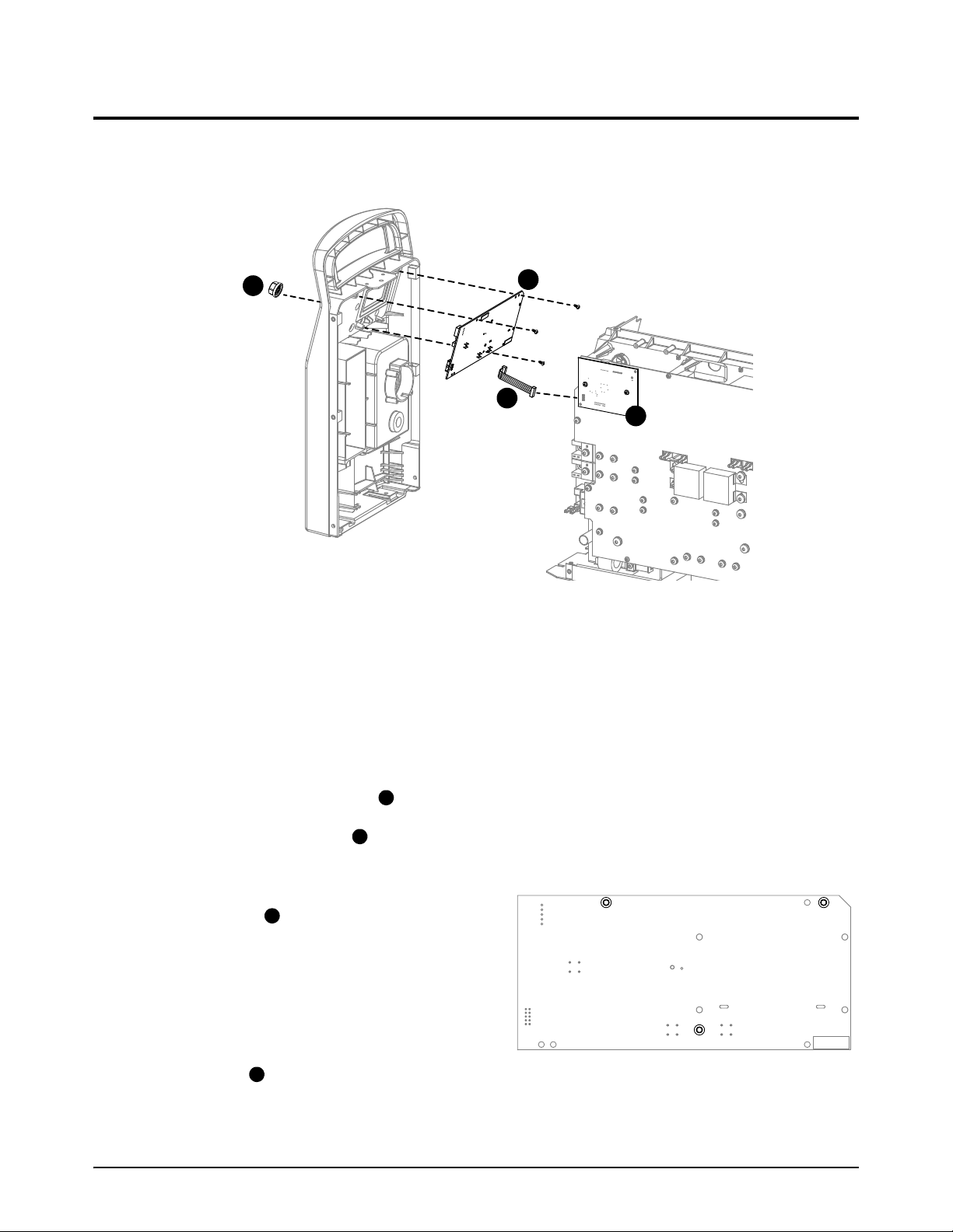
Service Procedures for the PCBs and Related Components
5
1
2
3
4
3
1
MTG
MTG
J6
2
4
Replace the control PCB and the ribbon cable
For kit contents, refer to Plasma power supply interior, front on page 23. The control PCB and the
ribbon cable are sold as different kits. The control PCB does not come with a ribbon cable.
Remove the control PCB and the ribbon cable
1. Set the power switch on the plasma power supply to OFF (O), disconnect the power cord, and
disconnect the gas supply.
2. Remove the plasma power supply cover and the component barrier. Refer to page 45.
3. Loosen the front panel. Refer to page 51.
4. Disconnect the ribbon cable from J6 on the control PCB.
5. Pull the adjustment knob off of its post on the front panel. If necessary, use a blade
screwdriver to carefully pry the knob off of the post.
6. Remove the 3 mounting screws from the
screwdriver. The screws have the label MTG.
7. From the power PCB side of the plasma
power supply, remove the control PCB from
the front panel.
8. Remove the left mounting screw from the
DSP PCB .
control PCB . Use an offset TORX
9. Disconnect the ribbon cable from J6 on the DSP PCB.
MTG
92 810450 Service Parts and Procedures Powermax105 SYNC

5
Install the control PCB and the ribbon cable
3
2
MTG
MTG
J6
1
4
1. Connect the ribbon cable to the J6 connector on the new control PCB .
2. From the power PCB side of the plasma power supply, put the control PCB into position in the
front panel as follows:
a. Tilt the bottom of the control PCB towards the front panel until it is on the plastic tabs in the
panel.
b. Push the post on the control PCB through the hole in the front panel.
3. Attach the control PCB to the front panel
with the 3 mounting screws. Tighten the
screws to 0.6 N·m (5 lbf·in).
Service Procedures for the PCBs and Related Components
MTG
4. Push the adjustment knob onto the post
in the front panel.
5. Attach the front panel. Refer to page 52.
6. Connect the ribbon cable to J6 on the DSB
PCB .
7. Install the left mounting screw in the DSP
PCB. Tighten the screw to 1.1 N·m (10 lbf·in).
8. Install the component barrier and the plasma
power supply cover. Refer to page 47.
Powermax105 SYNC Service Parts and Procedures 810450 93

Service Procedures for the PCBs and Related Components
5
Replace the power PCB
For kit contents, refer to Plasma power supply interior, power PCB side on page 25.
Refer to page 96 through page 97 for an image of your power PCB.
Remove the power PCB
1. Set the plasma power supply switch to OFF (O), disconnect the power cord from the power
source, and disconnect the gas supply.
2. Remove the plasma power supply cover and the component barrier. Refer to page 45.
3. Remove the end panel bracket. Refer to page 49.
4. Get a photograph of the power PCB so that you have a record of how all the screws and wires
are attached.
5. Remove the DSP PCB, as follows:
a. If you are using a serial connection, remove the DSP connector from J7 at the top of the
DSP PCB.
b. Remove the 2 mounting screws from the DSP PCB.
c. Be careful not to bend the pins as you pull the DSP PCB away from the power PCB.
d. Disconnect the ribbon cable from J6 on the DSP PCB.
e. Set aside the DSP PCB in an anti-static bag.
94 810450 Service Parts and Procedures Powermax105 SYNC

Service Procedures for the PCBs and Related Components
5
J1
J2
J5
J6
123
6. Disconnect the 4 wire connectors near the top of the power PCB.
For step 7 through step 14, refer to Figure 1, Figure 2, and Figure 3.
7. Remove the 3 µF capacitors from near the center of the power PCB. The number of
capacitors is different for each system. Set aside the capacitors and the screws.
8. Disconnect the gate drive wire connectors .
9. CSA models and CE 230 V – 400 V models: Disconnect the PFC temperature sensor wire
connector .
10. Remove all of the remaining screws that attach the power PCB to the heatsink components and
to the center panel. Make sure that you identify where the screws go so that you know where to
install them on the new power PCB.
11 . Disconnect the J11 and J17 connectors from the left side of the power PCB.
12. If you are using a machine interface connection, disconnect the J18 and J32 connectors from
the left side of the power PCB.
13. Pull the right edge of the power PCB forward, and push the gate drive wires and PFC
temperature sensor wire through the openings in the PCB.
14. Carefully remove the power PCB and set it aside in an anti-static bag.
Powermax105 SYNC Service Parts and Procedures 810450 95

Service Procedures for the PCBs and Related Components
5
J6
D38
J5 J2 J1
J22 J21 J20 J19
J27
WORK
LEAD
J26
J25
+
_
+
_
RED
J18
ORG
J17
RED
J32
J11
B
R
J28
C152 C151
TP7
TP9
TP8
W
R
B
1
2 3
J6 J5 J2 J1
RED
J18
ORG
J17
RED
J32
J11
B
R
J27
WORK
LEAD
J26
C152 C151
J25
+
_
+
_
J28
TP7
TP9
TP8
W
R
B
J22 J21 J20 J19
32
1
Figure 1 — Powermax105 SYNC CSA power PCB
Figure 2 — Powermax105 SYNC CE 230 V - 400 V power PCB
96 810450 Service Parts and Procedures Powermax105 SYNC

Service Procedures for the PCBs and Related Components
5
RED
J18
ORG
J17
RED
J32
J11
B
R
J27
J28
WORK
LEAD
J26
C152
C151
J25
+
_
+
_
TP7
TP9
TP8
W
R
B
J6 J5 J2 J1
J22 J21
1
2
Figure 3 — Powermax105 SYNC CCC 380 V / CE 400 V power PCB
Powermax105 SYNC Service Parts and Procedures 810450 97

Service Procedures for the PCBs and Related Components
5
123
4
Install the power PCB
1. Make sure that you have the correct power PCB for your system, as follows:
Powermax105 SYNC CSA models: Use power PCB 141458 (kit 528033).
Powermax105 SYNC CE 230 V – 400 V models: Use power PCB 141409 (kit 528034).
Powermax105 SYNC CCC 380 V / CE 400 V models: Use power PCB 141460
(kit 528035).
For step 2 through step 9, refer to Figure 4, Figure 5, and Figure 6. Install the screws shown
with gray shading first, then install the unshaded screws.
2. Connect the J11 and J17 connectors to the left side of the power PCB.
3. If you are using a machine interface connection, connect the J18 and J32 connectors to the left
side of the power PCB.
4. Put the gate drive wires and PFC temperature sensor wire through the openings in the power
PCB.
5. Make sure that all of the wires that are disconnected from the power PCB are in front of the
power PCB. Make sure none of the wires are pinched.
6. Install the following screws first. These screws are gray in Figure 4, Figure 5, and Figure 6.
Refer to these figures to make sure that the wires are attached in the correct location and
position.
a. Install the 3 µF capacitors near the center of the power PCB. Tighten the screws to
4.0 N·m (35 lbf·in).
b. Install the 4 screws for the bulk capacitors . Tighten the screws to 4.0 N·m (35 lbf·in).
c. Install the screws that attach the power switch wires to the power PCB. Tighten the
screws to 4.0 N·m (35 lbf·in).
d. Install the remaining larger screws across the middle of the power PCB. Tighten the screws
to 4.0N·m (35lbf·in).
7. Attach the correct wires to the power PCB at J25, J26, and J27. Tighten the bolts to 7.3 Nm
(65 lbfin).
8. Install all of the remaining screws on the power PCB. These screws are unshaded in Figure 4,
Figure 5, and Figure 6. Refer to these figures to make sure that the wires are attached in the
correct location and position. Tighten the screws to 1.7 N·m (15 lbf·in).
Install the 4 mounting screws last. Tighten these screws to 1.1 N·m (10 lbf·in).
9. Carefully connect the following wire connectors to the power PCB. Make sure that you do not
bend or damage the connectors.
All models: Connect the gate drive wires at J22 and J21.
CSA and CE 230 V – 400 V models: Connect the gate drive wire at J20 and the PFC
temperature sensor at J19.
98 810450 Service Parts and Procedures Powermax105 SYNC

Service Procedures for the PCBs and Related Components
5
J6
D38
J5 J2 J1
J22 J21 J20 J19
J27
WORK
LEAD
J26
J25
+
_
+
_
RED
J18
ORG
J17
RED
J32
J11
B
R
J28
C152 C151
TP7
TP9
TP8
W
R
B
2
3
1
4
4
J6 J5 J2 J1
RED
J18
ORG
J17
RED
J32
J11
B
R
J27
WORK
LEAD
J26
C152 C151
J25
+
_
+
_
J28
TP7
TP9
TP8
W
R
B
J22 J21 J20 J19
2
3
4
4
1
Figure 4 — Powermax105 SYNC CSA power PCB
Figure 5— Powermax105 SYNC CE 230 V - 400 V power PCB
Powermax105 SYNC Service Parts and Procedures 810450 99

Service Procedures for the PCBs and Related Components
5
RED
J18
ORG
J17
RED
J32
J11
B
R
J27
J28
WORK
LEAD
J26
C152
C151
J25
+
_
+
_
TP7
TP9
TP8
W
R
B
J6 J5 J2 J1
J22 J21
2
3
1
4
4
J1
J2
J5
J6
Figure 6— Powermax105 SYNC CCC 380 V / CE 400 V power PCB
10. Connect the 4 wire connectors near the top of the power PCB.
100 810450 Service Parts and Procedures Powermax105 SYNC
 Loading...