


600 Volt Conversion
Installation Manual
803200 - Rev. 0

600 Volt Conversion
Kit: 128312
Installation Manual
IM-320
(P/N 803200)
®
®
Revision 0 June, 1998
HYPERTHERM, Inc.
P.O. Box 5010
Hanover, New Hampshire 03755-5010
Tel.: (603) 643-3441
Fax: (603) 643-5352
http://www.hypertherm.com
email:info@hypertherm.com
© Copyright 1998 Hypertherm, Inc.
All Rights Reserved
HYPERTHERM and POWERMAX are trademarks of Hypertherm, Inc. and may be
registered in the United States and/or other countries

Hypertherm Offices Worldwide
Hypertherm, Inc.
Etna Road, P.O. Box 5010
Hanover, NH 03755 USA
Tel.: (603) 643-3441 (Main Office)
Fax: (603) 643-5352 (All Departments)
Tel.: (800) 643-9878 (Technical Service)
Tel.: (800) 737-2978 (Customer Service)
Hypertherm Plasmatechnik GmbH
Technologiepark Hanau
Rodenbacher Chaussee 6
D–63457 Hanau-Wolfgang, Germany
Tel.: 49 6181 58 2100
Fax: 49 6181 58 2134
European Technical Support Organization (ETSO)
Technologiepark Hanau
Rodenbacher Chaussee 6
D–63457 Hanau-Wolfgang, Germany
Tel.: 49 6181 58 2100
Fax: 49 6181 58 2134
:
Hypertherm Singapore Pte Ltd
No. 19 Kaki Bukit Road 2
K.B. Warehouse Complex
Singapore 417847, Republic of Singapore
Tel.: 65 841 2489
Fax: 65 841 2490
Hypertherm U.K.
9 Berkeley Court • Manor Park
Runcorn, Cheshire, England WA7 1TQ
Tel.: 44 1928 579 074
Fax: 44 1928 579 604
Hypertherm France
10, Allée de I’lsara
F-95000 Cergy-Pontoise, France
Tel.: 33 1 34 24 03 05
Fax: 33 1 34 25 09 64
Hypertherm Italy
Via Stilicone 18
20154 Milan, Italy
Tel.: 39 2 34 53 22 11
Fax: 39 2 34 53 20 18

SPECIFICATIONS
Section 1 SPECIFICATIONS
In this section:
Introduction ........................................................................................1-2
Specifications ..................................................................................... 1-2
600 Volt Powermax900 Power Supply ..........................................1-2
600V Installation Manual
1-1

SPECIFICATIONS
INTRODUCTION
The instructions in this manual will enable a qualified electronics technician to convert the
208/240/480 volt Powermax900 or 208/240/480 volt Powermax800 power supply into a 600 volt
power supply. The kit (128312) contains a transformer and case, wheels, castors, and 2 line cords one to hook up to a line disconnect box or 3-phase plug, and a shorter cord to connect from the
transformer case to the link box at the rear of the Powermax - See Figure 2-1. See also
Section 3 for a list of parts for the 600 volt conversion kit.
When installation is complete, refer to the Operator Manual for setup, operating instructions and
maintenance of the Powermax system.
SPECIFICATIONS See the operator manual for Powermax800 specifications
600 Volt Powermax900 Power Supply
Rated Open Circuit Voltage (OCV) (U0) ..............300VDC
Rated Output Current (I2) ....................................20-50 amps
Rated Output Voltage (U2) ..................................120VDC
Duty Cycle (X) @ 40°C ....................................... 50% (I2=55A, U2=120V) See data tag on power
supply for more information on duty cycle
Ambient temperature/duty cycle..........................Power supplies will operate between +14°
and 104° F (-10° and +40° C). Power
supplies operated in an ambient
temperature above 86° F (30° C) may show
some decrease in duty cycle.
Apparent Input Power (S1) ..................................11.4kVA (U1I1)
Input Voltage (U1)/Input Current (I1)
@ 6.6 kw Output ................................................. 600V/12A - 3φ, 60 Hz
1-2
Dimensions and Weight:
Depth...................................................................23.1" (590 mm)
Width ...................................................................15.25" (390 mm)
Height..................................................................27.7" (700 mm)
Weight .................................................................128 pounds (58 kg)
Gas Type.............................................................Air or Nitrogen
Gas Quality, Air ...................................................Clean, dry, oil-free
Gas Quality, Nitrogen..........................................99.995% pure
Gas Inlet Pressure ..............................................90 psi (6.2 bar)
Gas Flow .............................................................360 scfh/6 scfm at 90 psi (170 l/min
at 6.2 bar) supplied to power supply
pressure regulator
Power Supply pressure regulator setting ............70 psi (4.8 bar) flowing
600V Installation Manual

600V INSTALLATION
Section 2 600V INSTALLATION
In this section:
Installation .........................................................................................2-2
Installation of Wheels and Casters to Transformer Case..................2-4
Wheel Installation .........................................................................2-4
Caster Installation.........................................................................2-4
Attaching Power Supply Bracket to Powermax900 Chassis .............2-6
Attaching 600V Transformer Case Assembly to
Powermax900 Chassis .....................................................................2-8
Switching Voltage Configuration to 480V ..........................................2-9
Hooking Up the Three-Phase Transformer Secondary Power Cord
from 600V Transformer Case Assembly to Powermax900 ...............2-10
Choosing Plug, Power Cord and Line Disconnect Box Fuse ............2-11
Power Cord Plug......................................................................2-11
Power Cord - 600V ..................................................................2-11
Line Voltage Disconnect Box and Fuses .................................2-11
600V Installation Manual
2-1

600V INSTALLATION
WARNING
INSTALLATION MUST BE PERFORMED ONLY BY HYPERTHERM DISTRIBUTORS OR
QUALIFIED ELECTRONICS TECHNICIANS!!
SHOCK HAZARD: Always turn off power, unplug cord from wall and wait 5 minutes before
removing any cover of the power supply! If power unit is directly connected to a line
disconnect box, place line disconnect switch to OFF position. Lock out and tag out switch
before proceeding!
See Section 3 for a parts list of the 128312 Powermax 600V conversion kit.
Note: All graphics and text in this document refer to the Powermax900. Unless otherwise noted, all
instructions apply to either the Powermax800 or Powermax900.
INSTALLATION
The installation of the 600V kit to the 208/240/480V Powermax900 involves 6 basic steps:
1. Installation of wheels and casters to the transformer case.
2. Attaching the 600V power supply bracket to the Powermax900 chassis.
3. Attaching the 600V case assembly to the Powermax900 chassis.
4. Switching the power supply voltage configuration to 480V.
5. Hooking up the three-phase transformer secondary power cord from the 600V
transformer case assembly to the Powermax900.
6. Choosing the plug, power cord and line disconnect box fuse.
WARNING
THE 208/240/480V POWERMAX900 POWER SUPPLY IS SET UP TO OPERATE AT 240V WITH
A SINGLE-PHASE INPUT. WHEN CONVERTED TO A 600V POWER SUPPLY, THE VOLTAGE CONFIGURATION IN THE POWER SUPPLY MUST BE SWITCHED TO 480V, AND THE
POWER CORD MUST BE HOOKED UP FOR THREE-PHASE OPERATION. See pages 2-9 to
2-10.
2-2
600V Installation Manual
600V INSTALLATION
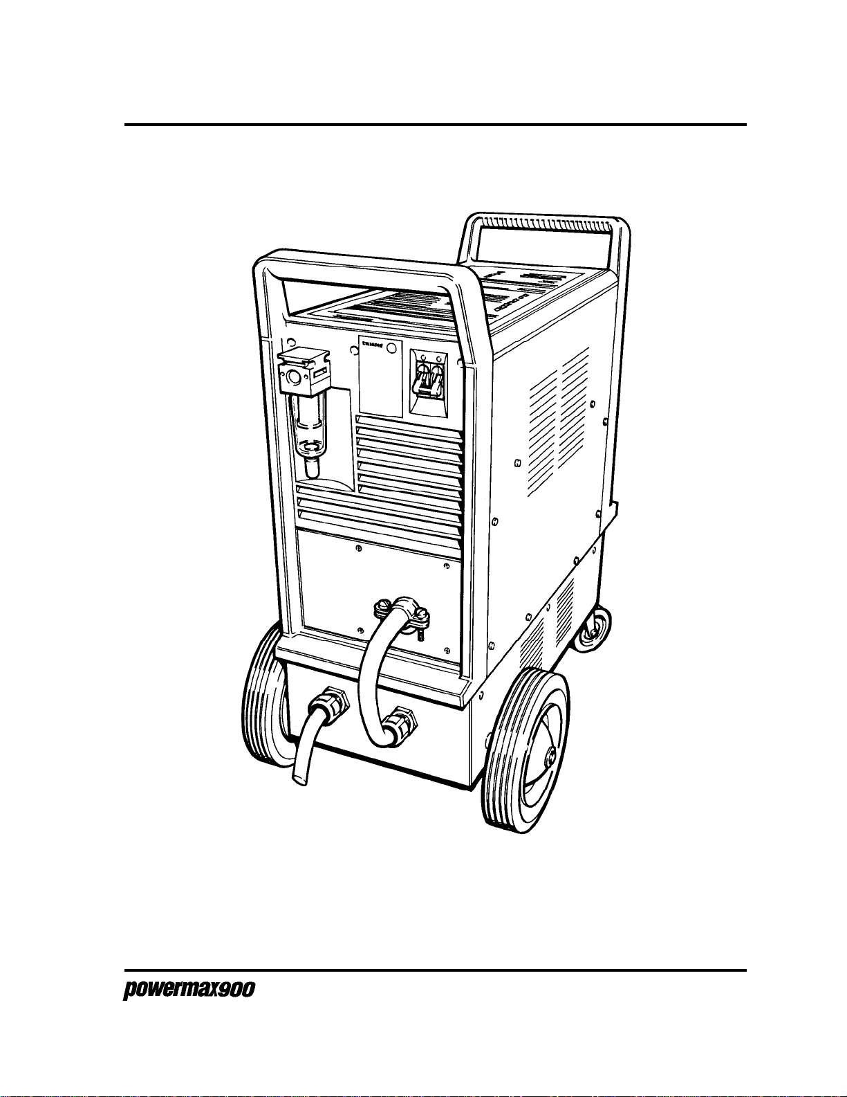
Figure 2-1 Powermax900 600V Power Supply Assembled
600V Installation Manual
2-3

600V INSTALLATION
INSTALLATION OF WHEELS AND CASTERS TO TRANSFORMER
CASE
Wheel Installation
1. Carefully turn transformer case assembly upside down.
2. Snap an 027249 retaining ring on one end of the 004672 wheel axle.
3. Slide one 027057 wheel on the axle.
4. Slide 008973 shoulder washer over the end of the axle with the larger diameter end of
the washer facing the mounted wheel.
5. Slide the axle through both holes in the rear of the transformer case assembly.
6. Slide the second 008973 shoulder washer over the end of the axle with the smaller
diameter end of the washer facing the transformer case.
7. Slide the second 027057 wheel onto the axle.
8. Snap the second 027249 retaining ring on the end of the axle to secure the second
wheel.
Caster Installation
1. Attach the 027299 casters to the case with the 075470 10-32 screws and 075174 star
washers as shown in Figure 2-2.
2. Turn transformer case back over on to wheels - Figure 2-3.
Wheel and caster installation complete.
2-4
600V Installation Manual

027299
Caster
600V INSTALLATION
075470
10-32 screws (8)
075174
10-32 star washers (8)
027057
Wheel
027249
Retaining
ring
008973
Shoulder
washer
004672
Axle
027057
Wheel
Figure 2-2 Wheel and Caster Installation
Figure 2-3 Wheels and Casters Installed on 600V Transformer Case
600V Installation Manual
2-5

600V INSTALLATION
ATTACHING POWER SUPPLY BRACKET TO POWERMAX900
CHASSIS.
1. If torch is connected to power supply, disconnect it.
WARNING
INSTALLATION MUST BE PERFORMED ONLY BY HYPERTHERM DISTRIBUTORS OR
QUALIFIED ELECTRONICS TECHNICIANS!!
SHOCK HAZARD: Always turn off power, unplug cord from wall and wait 5 minutes before
removing any cover of the power supply! If power unit is directly connected to a line
disconnect box, place line disconnect switch to OFF position and remove power cord from
line disconnect box.
2. Remove power cord from line disconnect box or from receptacle.
3. Remove power cord from power supply. See Figure 2-4.
3.1.Loosen the 2 screws on the power cord strain relief.
3.2.Remove the screws securing the line cord rear panel.
3.3.Slide rear panel down on power cord to expose link box.
3.4.Disconnect power cord from link box.
3.5.Remove power cord from rear panel.
Link Box
Loosen 2 screws
on power cord
strain relief.
Remove screws to
remove line cord
rear panel and
expose link box.
Figure 2-4 Removal of Power Cord from Powermax900 Power Supply
Green
Red (3φ)
White
Black
Remove power
cord wires from
link box.
2-6
600V Installation Manual

600V INSTALLATION
4. Remove the power supply cover (Powermax900 only).
5. Carefully tilt Powermax over onto its front handle as shown in Figure 2-5.
6. Place the 001568 power supply bracket against the bottom of the power supply as shown
in Figure 2-5 and fasten with the 075470 10-32 screws, 075174 star washers and
075160 kepnuts in 12 locations.
Note: The Powermax800 chassis does not require the 075160 kepnuts.
075160
Kepnuts (on inside)
(12)
075174
Star washers (12)
075470
Screws (12)
Figure 2-5 Attaching 600V Power Supply Bracket to Powermax Chassis
001568
Power supply
bracket
600V Installation Manual
2-7

600V INSTALLATION
ATTACHING 600V TRANSFORMER CASE ASSEMBLY TO
POWERMAX900 CHASSIS
1. Replace the power supply cover.
2. Lift Powermax over transformer case assembly with the rear of the power supply lined up
over the power cord side of the transformer case.
3. Carefully set down the Powermax onto the transformer case assembly.
4. Fasten the Powermax to the transformer case assembly by screwing in the 075467
8-32 screws in 10 locations.
5. Thread the transformer secondary power cord (shorter cord) through the strain relief of
the line cord rear panel.
Transformer
Secondary
Power Cord
Figure 2-6 Attaching 600V Transformer Case Assembly to Powermax900 Chassis
2-8
075467
8-32 screw
600V Installation Manual

600V INSTALLATION
SWITCHING VOLTAGE CONFIGURATION TO 480V
1. Configure TB2 by moving the voltage link wire (Black) to the position shown in Figure 2-7.
Link Box
TB3
TB2
Jumper
480V (Black)
GND (White)
Figure 2-7 Switching Voltage Configuration to 480V
2. Configure TB3 with one jumper linked in the position shown in Figure 2-7.
3. Secure unused link jumper in the clip located in the link box,
600V Installation Manual
2-9

600V INSTALLATION
HOOKING UP THE THREE-PHASE TRANSFORMER SECONDAR Y
POWER CORD FROM 600V TRANSFORMER CASE ASSEMBLY TO
POWERMAX900
1. Connect L1 (Black), L2 (White) and L3 (Red) of the three-phase transformer secondary
power cord to TB1 of the link box as shown in Figure 2-8.
2. Connect the ground (Green) wire to the stud marked above the terminal block .
Conductor Color
L1 Black
L2 White
Link Box
Green
TB1
Red
L3 Red
Ground Green
White
Black
Figure 2-8 Connecting the Transformer Secondary Power Cord
from 600V Transformer Case to Powermax900
3. Connect the rear panel to the Powermax900 power supply and secure with screws.
4. Tighten the strain relief screws around the power cord. Be certain that the strain relief
grips the outer insulation of the power cord and not the individual wires. See completed
assembly in Figure 2-1.
WARNING
BE CERTAIN THAT WIRES ARE CONNECTED EXACTLY AS SHOWN ABOVE. AS A
PRECAUTION, CHECK CONTINUITY FROM POWER SUPPLY ENCLOSURE TO INCOMING
GROUND WIRE BEFORE CONNECTING TO POWER.
2-10
600V Installation Manual

600V INSTALLATION
CHOOSING PLUG, POWER CORD AND LINE DISCONNECT BOX
FUSE
Power Cord Plug
The 600V Powermax900 kit is shipped with a three-phase power cord and no plug. The user
must obtain a plug that is certified by national or local electrical codes. The plug should be connected
to the power cord by a licensed electrician.
Power Cord - 600V
If the three-phase power cord length needs to be changed, use the table below to choose the proper
gauge size for the appropriate length. Use a 4-conductor SO type cord for three-phase power
supplies. The cord should be installed only by a licensed electrician.
Input Input Recommended Power Cord Gauge Size (AWG)
Voltage Current to 10 ft 10 – 25 ft 25 – 50 ft 50 – 100 ft 100 –150 ft
600 VAC 8 amps 12 12 12 12 10
Line Voltage Disconnect Box and Fuse
Use a line disconnect box for each power supply. This disconnect box allows the operator to turn the
power supply off quickly in an emergency situation. The switch should be located on a wall near the
power supply, and should be easily accessible to the operator. The interrupt level of the switch must
be equal to or exceed the continuous rating of the fuses. Use slow-blow fuses according to the power
requirements listed below.
Input Input Current Recommended
Voltage Phase @ 6.6 kw Output Slow-Blow Fuse Size
600 VAC 3 12 amps 20 amp
The 600Volt conversion is now complete. See the Powermax Operator Manual for further instructions
to setup, operate and maintain the Powermax system.
600V Installation Manual
2-11

600V INSTALLATION
2-12
600V Installation Manual

PARTS LIST
Section 3 PARTS LIST
In this section:
Powermax900 600 Volt Conversion Kit - 128312..............................3-2
600V Installation Manual
3-1

PARTS LIST
POWERMAX900 600 VOLT CONVERSION KIT - 128312
Index No. Part No. Description Quantity
1 001568 Panel:Powermax800 600V 1
2 004672 Axle:Powermax800 Power Unit 1
3 008973 Shoulder Washer:1/2" X 27/64 Nylon 2
4 027057 Wheel:8" X 1.75" 2
5 027249 Retaining Ring:1/2" Shaft Extension 2
6 027299 Caster:MAX70 Swivel 2
7 075467 M/S:8-32 X 3/8 Phillips Head Round SSB 10
8 075470 M/S:10-32 X 3/4 Phillips Head Pan 20
9 075174 Lockwasher :#10 Internal 20
075160 Kepnut:10-32 S/Z 12
129364 Powermax900 600V Conversion SA 1
10 001672 Cover:Powermax900 600V 1
11 001570 Bracket:Powermax800 600V 2
12 008752 Fuseblock:3Position 30A600V 13/32X1-1/2 1
13 008949 Terminal board:3-Terminal 1
14 008962 Fuse:20A 600V .406X1.5 Slow 3
15 008963 Strain relief:3/4" X .625-.750 2
16 014235 Transformer:Powermax900 600V Input 1
17 123060 Cable:Powermax800 600V Conv. Fuses 1
18 123061 Cable:Powermax800 600V Conv. Term. Block 1
1
5
10
Figure 3-1 Powermax900 600V Panel, Wheels and Casters
8
4
3
2
9
6
3
6
4
5
3-2
600V Installation Manual

PARTS LIST
12
14
16
10
11
7
13
17
15
18
Figure 3-2 Powermax900 600V Conversion Subassembly - 129364
600V Installation Manual
3-3

Wiring Diagram: Powermax900 600V Transformer - 014235
 Loading...