


Plasma Arc
Cutting System
Operator Manual
802730 Revision 2
®
EN50199
EN50192
powermaxpowermax11001100

Plasma Arc Cutting System
Operator Manual
IM-273
(P/N 802730)
for systems beginning with serial number
1100-010000
Revision 2 November, 2013
© Copyright 2013 Hypertherm, Inc.
All Rights Reserved
Hypertherm, HyDefinition, HT, HyLife, LongLife, MAX, PAC and Powermax are trademarks of Hypertherm, Inc.,
and may be registered in the United States and/or other countries
Hypertherm, Inc.
Hanover, NH
http://www.hypertherm.com
email:info@hypertherm.com

Hypertherm Offices Worldwide
Hypertherm, Inc.
Etna Road, P.O. Box 5010
Hanover, NH 03755 USA
Tel.: (603) 643-3441 (Main Office)
Fax: (603) 643-5352 (All Departments)
Tel.: (800) 643-9878 (Technical Service)
Tel.: (800) 737-2978 (Customer Service)
email: info@hypertherm.com (General Information)
email: service@hypertherm.com (Technical/Customer Services)
Hypertherm Plasmatechnik GmbH
Technologiepark Hanau
Rodenbacher Chaussee 6
D–63457 Hanau-Wolfgang, Germany
Tel.: 49 6181 58 2100
Fax: 49 6181 58 2134
European Technical Support Organization (ETSO)
Technologiepark Hanau
Rodenbacher Chaussee 6
D–63457 Hanau-Wolfgang, Germany
Tel.: 49 6181 58 2100
Fax: 49 6181 58 2134
:
Hypertherm Singapore Pte Ltd
No. 19 Kaki Bukit Road 2
K.B. Warehouse Complex
Singapore 417847, Republic of Singapore
Tel.: 65 841 2489
Fax: 65 841 2490
Hypertherm U.K.
9 Berkeley Court • Manor Park
Runcorn, Cheshire, England WA7 1TQ
Tel.: 44 1928 579 074
Fax: 44 1928 579 604
France
10, Allée de I’lsara
F-95000 Cergy-Pontoise, France
Tel.: 33 1 34 24 03 05
Fax: 33 1 34 25 09 64
Italy
Via Torino 2
20123 Milan, Italy
Tel.: 39 02 725 46 312
Fax: 39 02 725 46 400

E
LECTROMAGNETIC COMPATIBILITY
EMC INTRODUCTION
The 230/400V CE power supply has been
built in compliance with standard
EN50199. To ensure that the equipment
works in a compatible manner with other
radio and electronic systems, the
equipment should be installed and used in
accordance with the information below to
achieve electromagnetic compatibility.
The limits required by EN50199 may not
be adequate to completely eliminate
interference when the affected equipment
is in close proximity or has a high degree
of sensitivity. In such cases it may be
necessary to use other measures to
further reduce interference.
This plasma equipment should be used
only in an industrial environment. It may
be difficult to ensure electromagnetic
compatibility in a domestic environment.
INSTALLATION AND USE
The user is responsible for installing and
using the plasma equipment according to
the manufacturer's instructions. If
electromagnetic disturbances are
detected then it shall be the responsibility
of the user to resolve the situation with the
technical assistance of the manufacturer.
In some cases this remedial action may be
as simple as earthing the cutting circuit,
see
Earthing of Workpiece
it could involve constructing an
electromagnetic screen enclosing the
power source and the work complete with
associated input filters. In all cases
electromagnetic disturbances must be
reduced to the point where they are no
longer troublesome.
ASSESSMENT OF AREA
Before installing the equipment the user
shall make an assessment of potential
electromagnetic problems in the
surrounding area. The following shall be
taken into account:
a. Other supply cables, control cables,
signalling and telephone cables; above,
below and adjacent to the cutting
equipment.
b. Radio and television transmitters and
receivers.
c. Computer and other control equipment.
d. Safety critical equipment, for example
guarding of industrial equipment.
. In other cases
e. Health of the people around, for
example the use of pacemakers and
hearing aids.
f. Equipment used for calibration or
measurement.
g. Immunity of other equipment in the
environment. User shall ensure that
other equipment being used in the
environment is compatible. This may
require additional protection measures.
h. Time of day that cutting or other
activities are to be carried out.
The size of the surrounding area to be
considered will depend on the structure of
the building and other activities that are
taking place. The surrounding area may
extend beyond the boundaries of the
premises.
METHODS OF REDUCING
EMISSIONS
Mains Supply
Cutting equipment should be connected
to the mains supply according to the
manufacturer's recommendations. If
interference occurs, it may be necessary
to take additional precautions such as
filtering of the mains supply.
Consideration should be given to
shielding the supply cable of permanently
installed cutting equipment, in metallic
conduit or equivalent. Shielding should
be electrically continuous throughout its
length. The shielding should be
connected to the cutting mains supply so
that good electrical contact is maintained
between the conduit and the cutting
power source enclosure.
Maintenance of Cutting Equipment
The cutting equipment should be
routinely maintained according to the
manufacturer's recommendations. All
access and service doors and covers
should be closed and properly fastened
when the cutting equipment is in
operation. The cutting equipment should
not be modified in any way except for
those changes and adjustments covered
in the manufacturer's instructions. In
particular, the spark gaps of arc striking
and stabilizing devices should be
adjusted and maintained according to the
manufacturer's recommendations.
Cutting Cables
The cutting cables should be kept as
short as possible and should be
positioned close together, running at or
close to the floor level.
Equipotential Bonding
Bonding of all metallic components in the
cutting installation and adjacent to it
should be considered. However, metallic
components bonded to the workpiece will
increase the risk that the operator could
receive a shock by touching these
metallic components and the electrode at
the same time. The operator should be
insulated from all such bonded metallic
components.
Earthing of Workpiece
Where the workpiece is not bonded to
earth for electrical safety, nor connected
to earth because of its size and position,
for example, ship's hull or building
steelwork, a connection bonding the
workpiece to earth may reduce
emissions in some, but not all instances.
Care should be taken to prevent the
earthing of the workpiece increasing the
risk of injury to users, or damage to other
electrical equipment. Where necessary,
the connection of the workpiece to earth
should be made by a direct connection to
the workpiece, but in some countries
where direct connection is not permitted,
the bonding should be achieved by
suitable capacitances selected
according to national regulations.
Note: The cutting circuit may or may not
be earthed for safety reasons. Changing
the earthing arrangements should only
be authorized by a person who is
competent to assess whether the
changes will increase the risk of injury, for
example, by allowing parallel cutting
current return paths which may damage
the earth circuits of other equipment.
Further guidance is given in IEC TC26
(sec)94 and IEC TC26/108A/CD Arc
Welding Equipment Installation and Use.
Screening and Shielding
Selective screening and shielding of
other cables and equipment in the
surrounding area may alleviate problems
of interference. Screening of the entire
plasma cutting installation may be
considered for special applications.
Operator Manual
i

W
ARRANTY
WARNING
Genuine Hypertherm parts are the factory-recommended replacement parts for your
Hypertherm system. Any damage caused by the use of other than genuine
Hypertherm parts may not be covered by the Hypertherm warranty.
GENERAL
HYPERTHERM, Inc. warrants that Products shall be free from defects in materials and workmanship,
under proper and normal use for which such Equipment is recommended, for a period of two (2) years,
except only with respect to the Torch, for which the warranty period shall be one (1) year, from the date
of its delivery to you.
HYPERTHERM, at its sole option, shall repair, replace, or adjust, free of charge, any Products covered
by this warranty which shall be returned with HYPERTHERM's prior authorization (which shall not be
unreasonably withheld), properly packed, to HYPERTHERM's place of business in Hanover, New
Hampshire, all costs, insurance and freight prepaid, and which examination proves not to be free from
defects in materials and workmanship. HYPERTHERM shall not be liable for any repairs, replacements, or adjustments of Products covered by this warranty, except those made pursuant to this paragraph or with HYPERTHERM's written consent. This warranty shall not apply to any Product which has
been mishandled, incorrectly installed, modified or assembled by you or any other person. HYPERTHERM shall be liable for breach of this warranty only if it receives written notice of such breach within
the applicable warranty period specified herein above. THE FOREGOING SHALL CONSTITUTE THE
SOLE REMEDY TO DISTRIBUTORS OR THEIR CUSTOMERS FOR ANY BREACH BY HYPERTHERM OF ITS WARRANTY.
PATENT INDEMNITY
Except only in cases of Products not manufactured by HYPERTHERM or manufactured by a person
other than HYPERTHERM not in strict conformity with HYPERTHERM's specifications, and in cases of
designs, processes, formulae or combinations not developed or purported to be developed by HYPERTHERM, HYPERTHERM agrees to indemnify, protect and hold harmless Distributors and their customers against any and all liability or claims in any manner imposed upon or accruing against Distributors
and their customers because of the use in or about the construction or operation of Equipment or any
design, system, formula, combination, article or material which infringes or alleges to infringe on any
patent or other right. Distributors shall notify HYPERTHERM promptly upon learning of any action or
threatened action in connection with any such alleged infringement, and each party may appoint its own
counsel for any such action or threatened action.
DISCLAIMER OF OTHER WARRANTIES
HYPERTHERM MAKES NO WARRANTIES REGARDING PRODUCTS MANUFACTURED BY IT OR
OTHERS (INCLUDING WITHOUT IMPLIED LIMITATION WARRANTIES AS TO MERCHANTABILITY
OR FITNESS FOR A PARTICULAR PURPOSE), EITHER EXPRESS OR IMPLIED, EXCEPT AS
PROVIDED HEREIN. This warranty is in lieu of any and all warranties, express or implied, by law or
otherwise; and Distributors are not authorized to give any other warranty purporting to be binding upon
HYPERTHERM upon resale of Products to their customers. IN NO EVENT shall HYPERTHERM be
liable for incidental or consequential damages or injury to the person or property of anyone by reason of
any defect in any Equipment sold hereunder.
ii
Operator Manual

TABLE OF CONTENTS
ELECTROMAGNETIC COMPATIBILITY .................................................................................. i
WARRANTY ............................................................................................................................ ii
SECTION 1 SAFETY ........................................................................................................ 1-1
About Notes, Cautions & Warnings...................................................................................... 1-2
Safety Instructions................................................................................................................ 1-2
Eye Protection ................................................................................................................ 1-2
Skin Protection................................................................................................................ 1-2
Toxic Fume Prevention.................................................................................................... 1-2
Fire Prevention................................................................................................................ 1-2
Electric Shock Prevention ............................................................................................... 1-2
Explosion Prevention ...................................................................................................... 1-3
Noise Prevention............................................................................................................. 1-4
Grounding ....................................................................................................................... 1-4
Safety Reminders ........................................................................................................... 1-4
Electronic Health Support Equipment............................................................................. 1-4
SECTION 1A SÉCURITÉ ................................................................................................. 1a-1
Au sujet des Notes, Attention et avertissement.................................................................. 1a-1
Consignes de sécurité........................................................................................................ 1a-2
Protection des yeux ...................................................................................................... 1a-2
Protection de la peau .................................................................................................... 1a-2
Prévention des vapeurs toxiques .................................................................................. 1a-2
Prévention des incendies.............................................................................................. 1a-2
Prévention des chocs électriques ................................................................................. 1a-2
Prévention des explosions ............................................................................................ 1a-3
Protection contre le bruit ............................................................................................... 1a-4
Mise à la masse et à la terre......................................................................................... 1a-4
Rappels de sécurité ...................................................................................................... 1a-4
Prothèses électroniques ............................................................................................... 1a-4
SECTION 2 SPECIFICATIONS ...................................................................................... 2-1
Introduction .......................................................................................................................... 2-2
Specifications ....................................................................................................................... 2-3
PAC135 80A Torches .......................................................................................................... 2-4
IEC Symbols Used ............................................................................................................... 2-6
Operator Manual
iii

TABLE OF CONTENTS
SECTION 3 SETUP ........................................................................................................ 3-1
Upon Receipt ....................................................................................................................... 3-2
Claims .................................................................................................................................. 3-2
Hoisting Requirements ......................................................................................................... 3-3
Voltage Configurations ......................................................................................................... 3-4
Power Cords - 208/240/480V, 200/230/400V and 600V Power Supplies ............................. 3-5
Power Cords - 230/400V CE Power Supplies ...................................................................... 3-6
Changing the Strain Relief Sleeve ....................................................................................... 3-6
Single-Phase and Three-Phase Power Configurations........................................................ 3-7
Power Cord Plugs ................................................................................................................ 3-8
Power Requirements............................................................................................................ 3-8
Grounding Requirements ..................................................................................................... 3-8
Work Cable and Clamp ........................................................................................................ 3-9
Gas Supply Requirements ................................................................................................... 3-9
Gas Supply Connection ..................................................................................................... 3-10
Torch Lead Connection .......................................................................................................3-11
Machine Interface with PAC135M ...................................................................................... 3-12
SECTION 4 OPERATION ............................................................................................... 4-1
Controls and Indicators ........................................................................................................ 4-2
Operating Instructions .......................................................................................................... 4-3
Operating Tips...................................................................................................................... 4-6
Cut Chart - 80A Standard Consumables............................................................................ 4-12
Cut Chart - 40A Consumables ........................................................................................... 4-13
Common Cutting Faults ..................................................................................................... 4-14
SECTION 5 MAINTENANCE/PARTS............................................................................. 5-1
Introduction .......................................................................................................................... 5-2
Routine Maintenance ........................................................................................................... 5-2
Basic Troubleshooting.......................................................................................................... 5-4
Technical Questions............................................................................................................. 5-7
Parts ..................................................................................................................................... 5-8
Power Supplies - 208/240/480V......................................................................................... 5-12
Power Supplies - 200/230/400V......................................................................................... 5-12
Power Supplies - 200/400V CE.......................................................................................... 5-12
APPENDIX A STANDARDS INDEX .................................................................................. a-1
APPENDIX B AERATION MANIFOLD............................................................................. b-1
iv
Operator Manual
Section 1 SAFETY
In this section:
SAFETY
About Notes, Cautions and Warnings ..................... 1-1
Safety Instructions................................................... 1-2
Eye Protection .................................................. 1-2
Skin Protection ................................................. 1-2
Toxic Fume Prevention..................................... 1-2
Fire Prevention ................................................. 1-2
Electric Shock Prevention................................. 1-2
Explosion Prevention........................................ 1-3
Compressed Gas Cylinders .......................... 1-3
Pressure Regulators...................................... 1-3
Hoses ............................................................ 1-3
Noise Protection .................................................. 1-4
Grounding ............................................................ 1-4
Input Power ................................................... 1-4
Work Cable.................................................... 1-4
Work Table .................................................... 1-4
Safety Reminders ................................................ 1-4
Electronic Health Support Equipment.................. 1-4
Before using this plasma arc system. . . .
Each person who will operate this equipment, perform
service or maintenance, or supervise its use must read
the safety instructions and warnings in this manual and
the labels on the equipment.
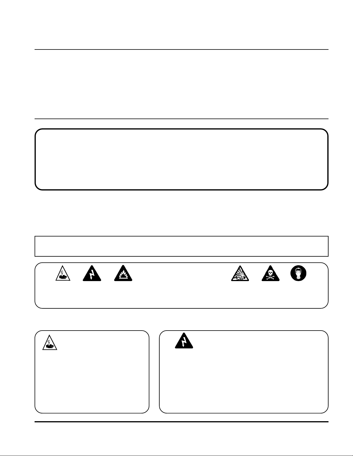
About Notes, Cautions and Warnings
Notes: Throughout this manual, useful information for operating the plasma system is presented in “notes”,
such as shown in this paragraph.
Cautions: Information in bold type and surrounded by a box describes a situation that may cause
damage to the plasma system.
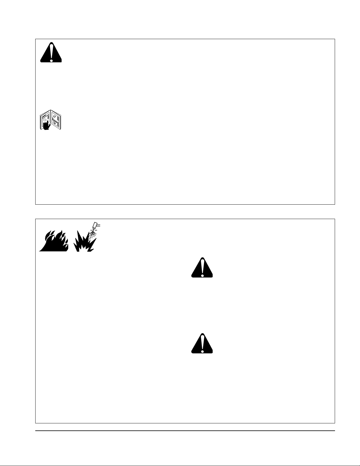
WARNINGS
Warnings describe situations that present a physical danger to the operator, and advice to avoid or
correct the situation. Each type of warning includes applicable danger symbols, such as a hand burn,
electrical shock, fire, explosion, etc.
WARNING — Instant-On
Torches
Instant-on torches produce a plasma
arc immediately after the torch switch
is
pushed.
Always hold a hand torch away from
your body as a precaution against
accidental torch firing. Be aware of
this hazard, which has potential for
serious bodily injury.
• Never touch the torch body, workpiece or the water in
a water table when operating the plasma system.
• When using a water table, be sure that it is correctly
connected to earth ground.
• Operating the plasma system completes an electrical
circuit between the torch and the workpiece and
anything touching the workpiece. The workpiece is part
of the electrical circuit.
WARNING — Electric Shock
HYPERTHERM Plasma Systems
1-1
5-98

SAFETY
Eye Protection
• Wear dark safety glasses or goggles with side
shields, or a welding helmet, in accordance with
applicable national or local codes, to protect eyes
against the plasma arc’s ultraviolet and infrared rays.
Lens Shade
Arc Current AWS (USA) ISO-4850
Up to 100 A No. 8 No. 11
100–200 A No. 10 No. 11-12
200–400 A No. 12 No. 13
Over 400 A No. 14 No. 14
• Replace the glasses, goggles or helmet when the lens
becomes pitted or broken.
• Warn other people in the area not to look directly at
the arc unless they are wearing glasses, goggles or a
helmet.
• Prepare the cutting area in a manner that reduces the
reflection and transmission of ultraviolet light:
– Paint walls and other surfaces with dark colors to
reduce reflection.
– Install protective screens or curtains to reduce
ultraviolet transmission.
Skin Protection
• Wear protective clothing to protect against burns
caused by ultraviolet light, sparks and hot metal:
– Gauntlet gloves, safety shoes and hat.
– Flame-retardant clothing which covers all
exposed areas.
– Cuffless trousers to prevent entry of sparks and
slag.
Toxic Fume Prevention
• Keep the cutting area well ventilated.
• Remove all chlorinated solvents from the cutting area
before cutting. Certain chlorinated solvents
decompose when exposed to ultraviolet radiation to
form phosgene gas.
• Wear proper breathing mask and use proper
ventilation when cutting galvanized metal.
• Do not cut containers with toxic materials inside.
Clean containers that have held toxic materials
thoroughly before cutting.
WARNING — Toxic Fumes
Do not cut metal or painted metals
containing zinc, lead, cadmium or beryllium
unless the operator, or anyone else subjected
to the fumes, wears respiratory equipment or
an air-supplied helmet.
Fire Prevention
• Make fire extinguishers available in the
cutting area.
• Remove all combustible materials from the immediate
cutting area to a distance of at least 35 feet (10 m).
• Quench freshly cut metal or allow metal to cool
before handling it or bringing it into contact with
combustible materials.
• Never use a plasma system to cut containers with
potentially flammable materials inside. Such
containers must be thoroughly cleaned prior to
cutting.
• Ventilate potentially flammable atmospheres before
cutting with a plasma system. When cutting with
oxygen as the plasma gas, an exhaust ventilation
system is required.
• Never operate the plasma system in an atmosphere
which contains heavy concentrations of dust,
flammable gas or combustible liquid vapors unless
properly vented.
Electric Shock Prevention
All Hypertherm plasma systems use high
voltage (up to 300 VDC) to initiate the plasma
arc. Take the following precautions when
operating the plasma system:
• Wear insulated gloves and boots, and keep body and
clothing dry.
• Do not stand, sit or lie on—or touch—any wet surface
when using the plasma system.
• Maintain proper insulation against electrical shock. If
you must work in or near a damp area, use extreme
caution.
• Provide a wall-mounted disconnect switch with
properly sized fuses close to the power supply. This
switch allows the operator to turn the power supply off
quickly in an emergency situation.
• Conform to all local electrical codes for primary wiring
sizes and types.
• Inspect the primary power cord frequently for damage
or cracking of the cover. Bare wiring can kill. Do not
use a system with a damaged power cord. Replace a
damaged power cord immediately.
• Inspect the torch leads. Replace if frayed or
damaged.
• Do not pick up the workpiece, including the waste
cutoff, while you cut. Leave the workpiece in place or
on the workbench with the work cable attached during
the cutting process.
1-2
5-98
HYPERTHERM Plasma Systems
SAFETY
Electric Shock Prevention (continued)
• Before changing the torch parts, disconnect the main
power or unplug the power supply. After changing
torch parts and replacing the retaining cap, plug in the
power supply again.
• Never bypass or shortcut the safety interlocks.
• Before removing a power supply cover for
maintenance, disconnect the main power at the wall
disconnect switch or unplug the power supply. To
avoid exposure to severe electrical hazard, wait five
minutes after disconnecting the main power to allow
capacitors to discharge.
• Never operate the plasma system unless the power
supply unit covers are in place. Exposed power
supply connections present a severe electrical
hazard.
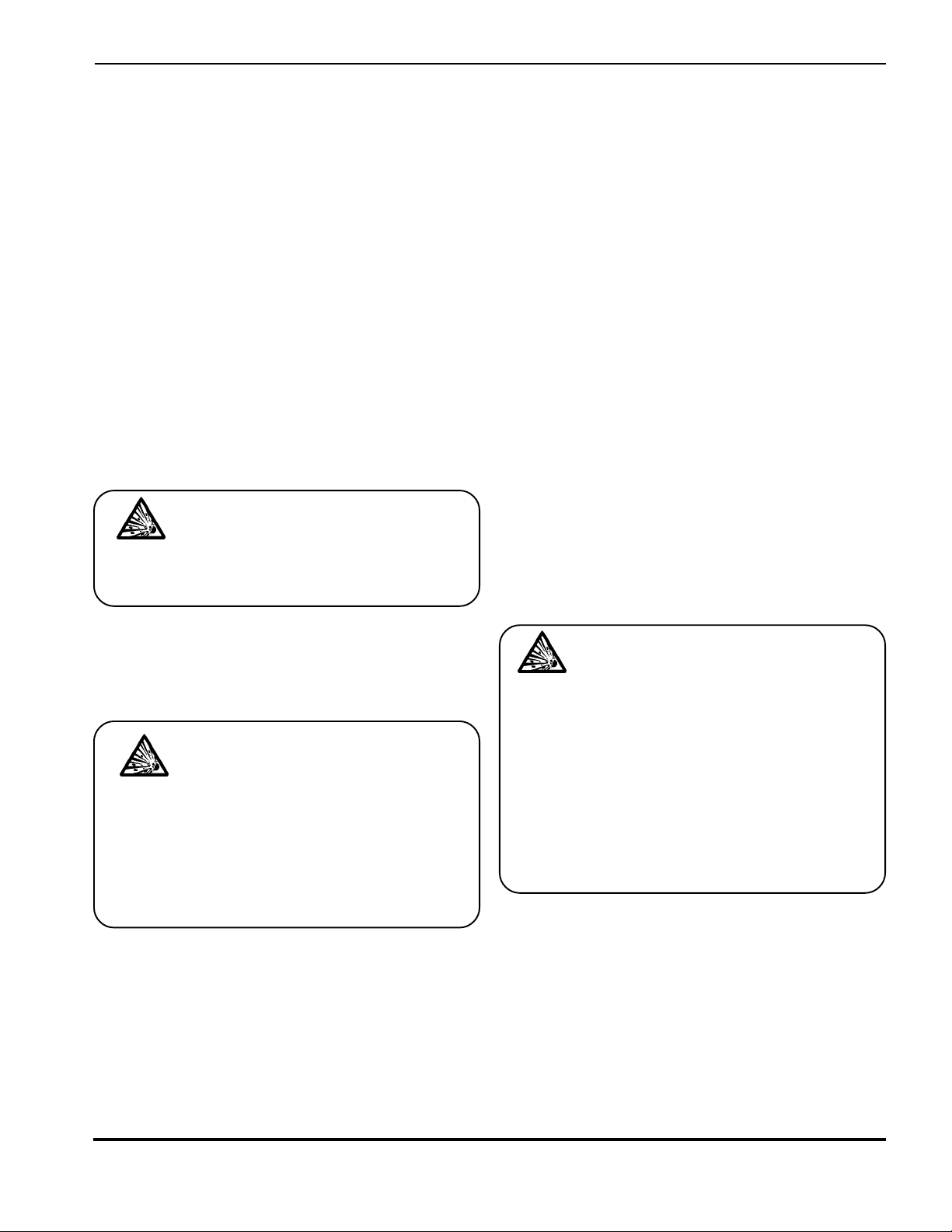
Explosion Prevention
WARNING — Compressed Gas
The plasma system uses compressed gas.
Observe proper precautions when handling and
using compressed gas equipment and cylinders.
• Never use a cylinder that is not upright and secured
in place.
• Never move or transport a cylinder without its
protective valve cover in place.
• Never use a gas cylinder or its contents for any
purpose other than that for which it is intended.
• Never lubricate cylinder valves with oil or grease.
• Never allow electrical contact between the plasma arc
and a cylinder.
• Never expose cylinders to excessive heat, sparks,
slag or open flame.
• Never use hammers, wrenches or other tools to open
stuck cylinder valves.
Pressure Regulators
• Be certain that all pressure regulators are in proper
working condition.
• Never use a regulator for any gas other than that for
which it is intended.
• Never use a regulator that leaks, creeps excessively
or is physically damaged in any way.
• Never attempt to lubricate a regulator with oil or
grease.
• Do not use the plasma system if explosive dust or
vapors may be present.
• Do not cut pressurized cylinders or any closed
container.
WARNING —
Hydrogen Explosion Hazard
If your system uses hydrogen, remember that this
is a flammable gas that presents an explosion
hazard. Keep flames away from cylinders
containing hydrogen mixtures and hoses that
carry hydrogen mixtures. Also, keep flames and
sparks away from the torch when using argonhydrogen as the plasma gas.
Compressed Gas Cylinders
Handle and use compressed gas cylinders in accordance with safety standards published by the U.S.
Compressed Gas Association (CGA), American Welding Society (AWS), Canadian Standards Association
(CSA) or applicable national or local codes.
• Never use a cylinder that leaks or is physically
damaged.
WARNING — Hydrogen Detonation
with Aluminum Cutting
When cutting aluminum underwater, or with the
water touching the underside of the aluminum,
free hydrogen gas may collect under the
workpiece and detonate during plasma cutting
operations.
Installing an aeration manifold on the floor of the
water table is an effective way to eliminate the
possibility of hydrogen detonation when cutting
aluminum. Refer to the Appendix section of this
manual for instructions on how to fabricate an
aeration manifold.
Hoses
• Label and color-code all gas hoses in order to clearly
identify the type of gas in each hose. Consult
applicable national or local codes.
• Never use the oxygen hose for any gas other than
oxygen.
• Examine hoses at regular intervals for leaks, wear,
loose connections or other hazard.
• Replace hose that is damaged in any way.
HYPERTHERM Plasma Systems
1-3
5-98

SAFETY
Hoses (continued)
• Keep hose lengths to a minimum to prevent damage,
reduce pressure drop and to prevent possible flow
restrictions.
• Prevent kinking by laying out hoses as straight as
possible between termination points.
• Coil any excess hose and place it out of the way to
prevent damage and to eliminate the danger of
tripping.
Noise Protection
The plasma cutting process can generate high
levels of noise. Depending on the arc current,
material being cut, acoustics and size of the
cutting room, distance from the torch and other factors,
acceptable noise levels as defined by national or local
codes may be exceeded by your plasma system.
• Always wear proper ear protection when cutting or
gouging with the plasma system.
Grounding
Input Power
• Be sure to connect the power cord ground wire to the
ground in the disconnect box.
• If installation of the plasma system involves
connecting the power cord to the power supply, be
sure to properly connect the power cord ground wire.
Conform to Canadian Standards Association (CSA)
standards by placing the power cord ground wire on
the stud first; then place any other ground wires on
top of the power cord ground. Fasten the retaining
nut tightly.
• Tighten all electrical connections to avoid excessive
heating.
Work Cable
• Attach the work cable securely to the workpiece or
the work table by making good metal-to-metal
contact.
Do not connect it to the piece that will fall away when
the cut is complete.
Work Table
• Connect the work table to an earth ground, in
accordance with appropriate national or local
electrical codes.
Safety Reminders
• Never bypass or shortcut the safety interlocks on any
of the plasma system units.
• Except in Hypertherm’s largest mechanized systems,
all Hypertherm torches are designed with a safety
interlock that prevents firing of the plasma arc when
the retaining cap is loosened.
• Each Hypertherm plasma system is designed to be
used only with specific Hypertherm torches. Do not
substitute other torches which could overheat and
present a potentially dangerous situation to the
operator and any personnel in the area. Hypertherm’s
warranty does not cover problems caused by the use
of torches not made by Hypertherm.
• Use only consumable parts and replacement parts
made by Hypertherm. Hypertherm’s warranty does
not cover problems caused by the use of parts not
made by Hypertherm.
• Never operate the plasma system with any of its
covers not in place. This would be hazardous to the
operator and other people in the area, and prevents
the proper cooling of the equipment.
Electronic Health Support Equipment
Plasma arc cutting and gouging systems create electric
and magnetic fields that may interfere with the correct
operation of electronic health support equipment, such
as pacemakers or hearing aids. Any person who wears
a pacemaker or hearing aid should consult a doctor
before operating or being near any plasma system
when it is in use. To minimize exposure to EMF:
• Keep both the work cable and the torch lead on one
side of your body. Keep your body from coming in
between the torch lead and the work cable.
• Route torch leads as close as possible to work cable.
• Do not wrap the torch lead or work cable around your
body.
• Stay as far away from the power supply as possible.
1-4
5-98
HYPERTHERM Plasma Systems
Section 1a SÉCURITÉ
SÉCURITÉ
IDENTIFIER LES CONSIGNES
DE SÉCURITÉ
Les symboles indiqués dans cette section sont utilisés pour
identifier les risques éventuels. Si vous trouvez un symbole
de sécurité, que ce soit dans ce manuel ou sur
l’équipement, soyez conscient des risques de blessures et
suivez les instructions correspondantes afin d’éviter ces
risques.
SUIVRE LES INSTRUCTIONS
DE SÉCURITÉ
Lire attentivement toutes les consignes de sécurité dans le
présent manuel et sur les étiquettes de sécurité se trouvant
sur la machine.
• Les étiquettes de sécurité doivent rester lisibles.
Remplacer immédiatement les étiquettes manquantes ou
abîmées.
• Apprendre à faire fonctionner la machine et à utiliser
correctement les commandes. Ne laisser personne utiliser
la machine sans connaître son fonctionnement.
• Garder la machine en bon état. Des modifications non
autorisées sur la machine peuvent engendrer des
problèmes de sécurité et raccourcir la durée d’utilisation
de l’équipement.
DANGER AVERTISSEMENT PRÉCAUTION
Les signaux DANGER ou AVERTISSEMENT sont utilisés
avec un symbole de sécurité, DANGER correspondant aux
risques les plus sérieux.
• Les étiquettes de sécurité DANGER et AVERTISSEMENT sont situées sur la machine pour signaler certains
dangers spécifiques.
• Les messages d’AVERTISSEMENT précèdent les
instructions d’utilisation expliquées dans ce manuel et
signalent les risques de blessures ou de mort au cas où
ces instructions ne seraient pas suivies correctement.
• Les messages de PRÉCAUTION précèdent les
instructions d’utilisation contenues dans ce manuel et
signalent que le matériel risque d’être endommagé si les
instructions ne sont pas suivies correctement.
LE COUPAGE PEUT PROVOQUER UN INCENDIE
OU UNE EXPLOSION
Prévention des incendies
• Avant de commencer, s’assurer que la zone de coupage
ne présente aucun danger. Conserver un extincteur à
proximité.
• Éloigner toute matière inflammable à une distance d’au
moins 10 m du poste de coupage.
• Tremper le métal chaud ou le laisser refroidir avant de
le manipuler ou avant de le mettre en contact avec des
matériaux combustibles.
• Ne jamais couper des récipients pouvant contenir des
matières inflammables avant de les avoir vidés et
nettoyés correctement.
• Aérer toute atmosphère potentiellement inflammable
avant d’utiliser un système plasma.
• Lors de l’utilisation d’oxygène comme gaz plasma, un
système de ventilation par aspiration est nécessaire.
Prévention des explosions
• Ne pas couper en présence de poussière ou de vapeurs.
• Ne pas couper de bouteilles, de tuyaux ou autres
récipients fermés et pressurisés.
• Ne pas couper de récipients contenant des matières
combustibles.
AVERTISSEMENT
Risque d’explosion
Argon-hydrogène et méthane
L’hydrogène et le méthane sont des gaz inflammables et
potentiellement explosifs. Conserver à l’écart de toute
flamme les bouteilles et tuyaux contenant des mélanges à
base d’hydrogène ou de méthane. Maintenir toute flamme
et étincelle à l’écart de la torche lors de l’utilisation d’un
plasma d’argon-hydrogène ou de méthane.
AVERTISSEMENT
Détonation de l’hydrogène lors du
coupage de l’aluminium
• Lors du coupage de l’aluminium sous l’eau, ou si l’eau
touche la partie inférieure de la pièce d’aluminium, de
l’hydrogène libre peut s’accumuler sous la pièce à couper
et détonner lors du coupage plasma.
• Installer un collecteur d’aération au fond de la table à eau
afin d’éliminer les risques de détonation de l’hydrogène.
Se référer à l’annexe du manuel pour plus de
renseignements sur les collecteurs d’aération.
HYPERTHERM Systèmes plasma 1a-1
10/6/98

SÉCURITÉ
LES CHOCS ÉLECTRIQUES PEUVENT ÊTRE FATALS
Toucher une pièce électrique sous tension peut provoquer
un choc électrique fatal ou des brûlures graves.
• La mise en fonctionnement du système plasma ferme un
circuit électrique entre la torche et la pièce à couper. La
pièce à couper et tout autre élément en contact avec cette
pièce font partie du circuit électrique.
• Ne jamais toucher le corps de la torche, la pièce à couper
ou l’eau de la table à eau pendant le fonctionnement du
système plasma.
Prévention des chocs électriques
Tous les systèmes plasma Hypertherm utilisent des hautes
tensions pour le coupage (souvent de 200 à 400 V).On doit
prendre les précautions suivantes quand on utilise le
système plasma :
• Porter des bottes et des gants isolants et garder le corps
et les vêtements au sec.
• Ne pas se tenir, s’asseoir ou se coucher sur une surface
mouillée, ni la toucher quand on utilise le système
plasma.
• S’isoler de la surface de travail et du sol en utilisant des
tapis isolants secs ou des couvertures assez grandes
pour éviter tout contact physique avec le travail ou le sol.
S’il s’avère nécessaire de travailler dans ou près d’un
endroit humide, procéder avec une extrême prudence.
• Installer un sectionneur avec fusibles appropriés, à
proximité de la source de courant. Ce dispositif permet à
l’opérateur d’arrêter rapidement la source de courant en
cas d’urgence.
• En cas d’utilisation d’une table à eau, s’assurer que cette
dernière est correctement mise à la terre.
• Installer et mettre à la terre l’équipement selon les
• Inspecter fréquemment le cordon d’alimentation primaire
• Inspecter et remplacer les câbles de la torche qui sont
• Ne pas saisir la pièce à couper ni les chutes lors du
• Avant de vérifier, de nettoyer ou de remplacer les pièces
• Ne jamais contourner ou court-circuiter les verrouillages
• Avant d’enlever le capot du système ou de la source de
• Ne jamais faire fonctionner le système plasma sans que
• Lors de l’installation des connexions, attacher tout d’abord
• Chaque système plasma Hypertherm est conçu pour être
instructions du présent manuel et conformément aux
codes électriques locaux et nationaux.
pour s’assurer qu’il n’est ni endommagé, ni fendu.
Remplacer immédiatement un cordon endommagé. Un
câble dénudé peut tuer.
usés ou endommagés.
coupage. Laisser la pièce à couper en place ou sur la
table de travail, le câble de retour connecté lors du
coupage.
de la torche, couper l’alimentation ou débrancher la prise
de courant.
de sécurité.
courant, couper l’alimentation électrique. Attendre ensuite
5 minutes pour que les condensateurs se déchargent.
les capots de la source de courant ne soient en place.
Les raccords exposés de la source de courant sont
extrêmement dangereux.
la prise de terre appropriée.
utilisé uniquement avec des torches Hypertherm
spécifiques. Ne pas utiliser des torches inappropriées qui
pourraient surchauffer et présenter des risques pour la
sécurité.
LE COUPAGE PEUT PRODUIRE DES VAPEURS TOXIQUES
Le coupage peut produire des vapeurs et des gaz toxiques
qui réduisent le niveau d’oxygène dans l’air et peuvent
provoquer des blessures, voire la mort.
• Conserver le poste de coupage bien aéré ou utiliser un
masque respiratoire homologué.
• Ne pas procéder au coupage près d’endroits où
s’effectuent le dégraissage, le nettoyage ou la
vaporisation. Certains solvants chlorés se décomposent
sous l’effet des rayons ultraviolets et forment du
phosgène.
1a-2
5/27/99
10/6/98
• Ne pas couper des métaux peints ou contenant des
matières toxiques comme le zinc (galvanisé), le plomb, le
cadmium ou le béryllum, à moins que la zone de travail
soit très bien ventilée et que l’opérateur porte un masque
respiratoire. Les revêtements et métaux contenant ces
matières peuvent produire des vapeurs toxiques lors du
coupage.
• Ne jamais couper de récipients pouvant contenir des
matières inflammables avant de les avoir vidés et
nettoyés correctement.
HYPERTHERM Systèmes plasma

SÉCURITÉ
L’ARC PLASMA PEUT PROVOQUER DES BLESSURES OU DES BRÛLURES
Torches à allumage instantané
L’arc plasma s’allume immédiatement après que la torche
soit mise en marche.
LES RAYONS DE L’ARC PEUVENT BRÛLER LES YEUX ET LA PEAU
Protection des yeux Les rayons de l’arc plasma
produisent de puissants rayons visibles ou invisibles
(ultraviolets et infrarouges) qui peuvent brûler les yeux et la
peau.
• Utiliser des lunettes de sécurité conformément aux codes
locaux ou nationaux en vigueur.
• Porter des lunettes de protection (lunettes ou masque
muni d’écrans latéraux ou encore masque de soudure)
avec des verres teintés appropriés pour protéger les yeux
des rayons ultraviolets et infrarouges de l’arc.
Puissance des verres teintés
Courant de l’arc AWS (É.-U.) ISO 4850
Jusqu’à 100 A No 8N
100-200 A No 10 No 11-12
200-400 A No 12 No 13
Plus de 400 A No 14 No 14
Protection de la peau Porter des vêtements de sécurité
pour se protéger contre les brûlures que peuvent causer les
rayons ultraviolets, les étincelles et le métal brûlant :
o
11
L’arc plasma coupe facilement les gants et la peau.
• Rester éloigné de l’extrémité de la torche.
• Ne pas tenir de métal près de la trajectoire de coupe.
• Ne jamais pointer la torche vers soi ou d’autres
personnes.
• Gants à crispin, chaussures et casque de sécurité.
• Vêtements ignifuges couvrant toutes les parties exposées
du corps.
• Pantalon sans revers pour éviter que des étincelles ou
des scories puissent s’y loger.
• Avant le coupage, retirer de ses poches tout objet
combustible comme les briquets au butane ou les
allumettes.
Zone de coupage Préparer la zone de coupage afin de
réduire la réverbération et la transmission de la lumière
ultraviolette :
• Peindre les murs et autres surfaces de couleur sombre
pour réduire la réflexion de la lumière.
• Utiliser des écrans et autres dispositifs de protection afin
de protéger les autres personnes de la lumière et de la
réverbération.
• Prévenir les autres personnes de ne pas regarder l’arc.
Utiliser des affiches ou des panneaux.
MISE À LA MASSE ET À LA TERRE
Câble de retour Bien fixer le câble de retour (ou de
masse) à la pièce à couper ou à la table de travail de façon
à assurer un bon contact métal-métal. Ne pas fixer le câble
de retour à la partie de la pièce qui doit se détacher.
Table de travail Raccorder la table de travail à la terre,
conformément aux codes de sécurité locaux ou nationaux
appropriés.
Alimentation
• S’assurer que le fil de terre du cordon d’alimentation est
connecté à la terre dans le coffret du sectionneur.
• S’il est nécessaire de brancher le cordon d’alimentation à
la source de courant lors de l’installation du système,
s’assurer que le fil de terre est correctement branché.
• Placer tout d’abord le fil de terre du cordon d’alimentation
sur le plot de mise à la terre puis placer les autres fils de
terre par-dessus. Bien serrer l’écrou de retenue.
• S’assurer que toutes les connexions sont bien serrées
pour éviter la surchauffe.
HYPERTHERM Systèmes plasma 1a-3
4/9/99
10/6/98

SÉCURITÉ
SÉCURITÉ DES BOUTEILLES DE GAZ
COMPRIMÉ
• Ne jamais lubrifier les robinets des bouteilles ou les
régulateurs avec de l’huile ou de la graisse.
• Utiliser uniquement les bouteilles, régulateurs, tuyaux et
accessoires appropriés et conçus pour chaque application
spécifique.
• Entretenir l’équipement et les pièces d’équipement à gaz
comprimé afin de les garder en bon état.
• Étiqueter et coder avec des couleurs tous les tuyaux de
gaz afin d’identifier le type de gaz contenu dans chaque
tuyau. Se référer aux codes locaux ou nationaux en
vigueur.
LE BRUIT PEUT PROVOQUER DES
PROBLÈMES AUDITIFS
LES BOUTEILLES DE GAZ
COMPRIMÉ PEUVENT EXPLOSER
EN CAS DE DOMMAGES
Les bouteilles de gaz contiennent du gaz à haute pression.
Si une bouteille est endommagée, elle peut exploser.
• Manipuler et utiliser les bouteilles de gaz comprimé
conformément aux codes locaux ou nationaux.
• Ne jamais utiliser une bouteille qui n’est pas placée à la
verticale et bien assujettie.
• Le capuchon de protection doit être placé sur le robinet
sauf si la bouteille est en cours d’utilisation ou connectée
pour utilisation.
• Éviter à tout prix le contact électrique entre l’arc plasma et
une bouteille.
• Ne jamais exposer des bouteilles à une chaleur
excessive, aux étincelles, aux scories ou aux flammes
nues.
• Ne jamais utiliser des marteaux, des clés ou d’autres
outils pour débloquer le robinet des bouteilles.
PACEMAKERS ET
PROTHÈSES AUDITIVES
Une exposition prolongée au bruit du coupage ou du
gougeage peut provoquer des problèmes auditifs.
• Utiliser un casque de protection homologué lors de
l’utilisation du système plasma.
• Prévenir les personnes aux alentours des risques
encourus en cas d’exposition au bruit.
Les champs magnétiques produits par les courants à haute
tension peuvent affecter le fonctionnement des prothèses
auditives et des pacemakers. Les personnes portant ce
type d’appareil doivent consulter un médecin avant de
s’approcher d’un lieu où s’effectue le coupage ou le
gougeage plasma.
Pour réduire les risques associés aux champs
magnétiques :
• Garder loin de soi et du même côté du corps le câble de
retour et le faisceau de la torche.
• Faire passer le faisceau de la torche le plus près possible
du câble de retour.
• Ne pas s’enrouler le faisceau de la torche ou le câble de
retour autour du corps.
• Se tenir le plus loin possible de la source de courant.
1a-4
10/6/98
10/16/98
HYPERTHERM Systèmes plasma

Section 2 SPECIFICATIONS
In this section:
S
PECIFICATIONS
Introduction ......................................................................................................2-2
Specifications ...................................................................................................2-3
Power Supply ..............................................................................................2-3
PAC135 80A Torches .......................................................................................2-4
PAC135T Hand Torch Assembly..................................................................2-5
PAC135M Machine Torch Assembly............................................................2-5
S Mark ........................................................................................................2-5
IEC Symbols Used ...........................................................................................2-6
Operator Manual
2-1

S
PECIFICATIONS
INTRODUCTION
The Powermax1100 plasma cutting system uses an inverter power supply to provide a smooth DC
output voltage, producing excellent cut and gouge quality on mild steel, stainless steel, aluminum and
other metals. The Powermax1100 power supply provides constant-current output variable from 30 to
80 amps, for optimum performance on all thicknesses of metal up to 3/4 inch (20 mm) thick. At 80
amps, the Powermax1100 can cut metals up to 1 inch (25 mm) thick and will sever metals up to 1-1/4
inch (32 mm) thick.
Air is the primary plasma gas, providing low operating cost combined with high-speed performance.
Cylinder air or shop air can be used as long as it is clean, dry and oil-free. When properly set and
maintained, the pressure regulator and gas filter on the power supply ensure that the correct pressure
and flow rate is supplied to the system at the proper quantity and quality. The Powermax1100 can also
cut with nitrogen when extended electrode life is a priority.
This instruction manual provides information for the user to set up and operate the system and perform
limited maintenance on the power supply. This manual also provides a detailed list of safety practices
so that the system can be safely operated and maintained. READ THE SAFETY SECTION
(Section 1) FIRST!
The Powermax1100 service manual provides higher-level troubleshooting and a more complete parts
list.
2-2
Figure 2-1 Powermax1100 Hand Plasma Cutting System
Operator Manual

SPECIFICATIONS
Power Supply
Rated Open Circuit Voltage (OCV) (U0) ............... 280-320 VDC
Rated Output Current (I2) ..................................... 30–80 amps
Rated Output Voltage (U2).................................... 140 VDC
Duty Cycle (X) @ 104° F (40° C) ......................... 50% (I2=80A, U2=140V)
Ambient temperature............................................ Power supplies will operate between +14° and
Apparent Input Power (S1).................................... 19.2 kVA (U1I1) non CE power supplies
Input Voltage (U1)/Input Current (I1)
@11.2 kw Output.................................................. 208V/92A; 240V/80A; 480V/40A - 1φ, 50/60 Hz
S
PECIFICATIONS
100% (I2=57A, U2=140V) See data tag on power
supply for more information on duty cycle
104° F (-10° and +40° C).
13.1 kVA (U1I1) CE power supplies
208V/53A; 240V/46A; 480V/23A - 3φ, 50/60 Hz
200V/96A; 230V/84A; 400V/48A - 1φ, 50/60 Hz
200V/56A; 230V/49A; 400V/28A - 3φ, 50/60 Hz
230V/33A; 400V/19A (CE) - 3φ, 50/60 Hz
600V/20A - 3φ, 60 Hz
Gas Type.............................................................. Air or Nitrogen
Gas Quality, Air .................................................... Clean, dry, oil-free
Gas Quality, Nitrogen ........................................... 99.995% pure
Gas Inlet Pressure................................................ 90 psi (6.2 bar)
Gas Flow .............................................................. 400 scfh/6.7 scfm at 90 psi (189 l/min at 6.2 bar)
supplied to power supply pressure regulator
Power Supply pressure regulator setting ............. 65 psi (4.5 bar) flowing
Dimensions and Weight:
Depth.................................................................... 25.1" (638 mm)
Width .................................................................... 10.4" (264 mm) without wheels
15.8" (401 mm) with wheels
Height ................................................................... 19.6" (498 mm) without wheels
23.7" (602 mm) with wheels
Weight, 208/240/480V and 200/230/400V
without power cord ............................................... 77 pounds (35 kg) without wheels
89 pounds (40 kg) with wheels
Weight, 230/400V CE with power cord................. 87 pounds (39 kg) without wheels
99 pounds (45 kg) with wheels
Weight, 600V with power cord.............................. 160 pounds (73 kg) with wheels
Operator Manual
2-3

S
PECIFICATIONS
10.4"
(264 mm)
25.1"
(638 mm)
19.6"
(498 mm)
Figure 2-2 Powermax1100 Power Supply Dimensions
19.6"
(498 mm)
PAC135 80A TORCHES
Maximum 80A Cutting Capacity (PAC135T).............. 1" (25 mm) @ 50% duty cycle
Recommended 80A Cutting Capacity (PAC135T) ..... 3/4" (20 mm) @ 100% duty cycle
Maximum 80A Cutting Capacity (PAC135M) ............. 1/2" (12 mm) @ 50% duty cycle
Recommended 80A Cutting Capacity (PAC135M) .... 3/8" (9.5 mm) @ 100% duty cycle
Maximum current at 50% duty cycle .......................... 80 amps
Gas Flow .................................................................... 400 scfh/6.7 scfm at 65 psi (189 l/min at
4.5 bar)
Gouging Capability (metal removal rate).................... 6.6 pounds (3.0 kg)/hr
Weight PAC135T ....................................................... 9.3 pounds (4.2 kg) with 25 ft (7.6 m) lead
17.8 pounds (8.1 kg) with 50 ft (15 m) lead
Weight PAC135M....................................................... 9.6 pounds (4.4 kg) with 25 ft (7.6 m) lead
18 pounds (8.2 kg) with 50 ft (15 m) lead
2-4
Operator Manual

PAC135T Hand Torch Assembly
4.8"
(122 mm)
3.5"
(89 mm)
1.2"
(30 mm)
Figure 2-3 PAC135T Torch with Dimensions
9.1"
(231 mm)
S
PECIFICATIONS
1.9"
(48 mm)
PAC135M Machine Torch Assembly
14"
3.3"
(83 mm)
1.8"
(45 mm)
1.2"
(30 mm)
55°
(356 mm)
10.8"
(274 mm)
Figure 2-4 PAC135M Torch with Dimensions
S MARK
The Powermax1100 conforms to standard EN50192. The S mark indicates that the power
supply and torch are suitable for use in environments with increased hazard of electrical shock. The
hand torches must have shielded consumable parts to maintain S mark compliance.
1.4"
(35 mm)
Operator Manual
2-5
S
PECIFICATIONS
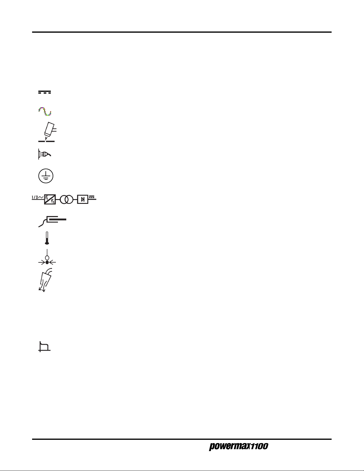
IEC SYMBOLS USED
Direct Current (DC)
Alternating current (AC)
Plasma cutting torch
AC input power connection
The terminal for the external protective (earth) conductor
An inverter-based power source
I
O
Anode (+) work clamp
Temperature switch
Pressure switch
Plasma torch in the TEST position (cooling and cutting gas exiting nozzle)
Power is on
Power is off
Volt/amp curve, "drooping" characteristic
2-6
Operator Manual

S
ETUP
Section 3 SETUP
In this section:
Upon Receipt....................................................................................................3-2
Claims...............................................................................................................3-2
Hoisting Requirements .....................................................................................3-3
Voltage Configurations...................................................................................... 3-4
Power Cords - 208/240/480V, 200/230/400V and 600V Power Supplies.........3-5
Power Cords - 230/400V CE Power Supplies ..................................................3-6
Changing the Strain Relief Sleeve....................................................................3-6
Single-Phase and Three-Phase Power Configurations..................................... 3-7
Single-Phase................................................................................................3-7
Three-Phase ................................................................................................3-7
Power Cord Plugs ............................................................................................. 3-8
Power Requirements ........................................................................................ 3-8
Line V oltage Disconnect Box........................................................................3-8
Grounding Requirements.................................................................................. 3-8
Work Cable and Clamp.....................................................................................3-9
Gas Supply Requirements................................................................................3-9
Air Supply Quality.........................................................................................3-9
Additional Air Filtration ...............................................................................3-10
Nitrogen Supply Quality .............................................................................3-10
Gas Supply Connection..................................................................................3-10
Torch Lead Connection................................................................................... 3-11
PAC135M ON/OFF Pendant Connection................................................... 3-11
PAC135M Torch ON/OFF Switch Connection Data ................................... 3-11
PAC135M Torch Alignment ........................................................................ 3-11
Machine Interface with PAC135M...................................................................3-12
Arc Voltage.................................................................................................3-13
Operator Manual
3-1

S
ETUP
UPON RECEIPT
1. Verify that all parts and items on your order have been received. Alert your distributor if any
parts or items are damaged or missing.
2. Inspect the power supply for any physical damage that may have occurred during shipping. If
there is evidence of damage, refer to the
All communications regarding this equipment must include the model number and serial number
located on the back of the Powermax1100.
3. Before setting up and operating the Powermax1100, read the Safety section of this manual.
Claims
section below.
CLAIMS
Claims for damage during shipment — If your unit was damaged during shipment, you must file a
claim with the carrier. Hypertherm will furnish you with a copy of the bill of lading upon request. If you
need additional assistance, call Customer Service at 1 800 643 0030 in the U.S. and Canada, or your
authorized Hypertherm distributor.
Claims for defective or missing merchandise — All units shipped from Hypertherm undergo rigorous
quality control inspections for defects. If any of the merchandise is defective or missing, call your
authorized Hypertherm distributor. If you need additional assistance, call Customer Service at 1 800
643 0030 in the U.S. and Canada, or your authorized Hypertherm distributor.
3-2
Operator Manual

HOISTING REQUIREMENTS
In the event that the power supply has to be hoisted, follow the steps below.
WARNING
The Powermax1100 power supply weighs up to 100 pounds (45 kg) when fully configured
with torch, torch leads and wheels. The fully configured 600V power supply weighs nearly
200 pounds (91 kg). Use a hoisting machine with a hoisting strap through both handles to
hoist the power supply. Always hoist the power supply with its cover secured in place. Do
not hoist the power supply by one handle; it is not designed to support the weight of the
power supply. Failure to heed this warning could result in personal injury and damage to
the power supply.
1. Use a hoisting strap rated for a minimum hoisting weight of 400 pounds (182 kg). Approved
hoisting straps have attached labels with ratings.
S
ETUP
2. Ensure the power supply cover is in place prior to hoisting.
3. Route the strap between the two handles as shown in Fig. 3-1.
4. Bring the strap ends together over the center of the power supply and connect them to the
hoisting machine.
5. Hoist and lower the power supply slowly and smoothly.
Approved hoisting
strap
Cover in place
Hoisting
Machine
Figure 3-1 Powermax1100 Power Supply Hoisting Setup
Operator Manual
3-3

S
ETUP
VOLTAGE CONFIGURATIONS
WARNING
SHOCK HAZARD: Always turn off the power, unplug the cord and wait 5 minutes before
removing any power supply cover. If the power supply is directly connected to a line
disconnect switch, place switch in the OFF position. In the U.S., use a "lock-out / tag-out"
procedure until the service or maintenance work is complete. In other countries, follow
appropriate local or national safety procedures.
The 208/240/480V Powermax1100 power supplies are shipped to operate at 480 volts. The
200/230/400V and 230/400V CE Powermax1100 power supplies are shipped to operate at 400 volts.
To operate at an alternate voltage, remove the rear panel, and configure the wires and jumpers on TB2
and TB3 as shown below.
Notes: • When switching from the 480V or 400V configuration, use the spare jumper in the clip located
on the floor of the power supply.
• If using the 600V transformer option kit, configure the Powermax1100 for 480V.
TB2
TB3
Black
White
Figure 3-2 Rear Panel
TB2
TB3
Black
White
Remove 8 screws to
remove panel
Approximate location
of TB2 and TB3
400V or 480V200V or 208V 230V or 240V
TB2
Black
White
TB3
Jumper
Figure 3-3 200V or 208V
Configuration
3-4
Figure 3-4 230V or 240V
Configuration
Figure 3-5 400V or 480V
Configuration
Operator Manual
S
ETUP
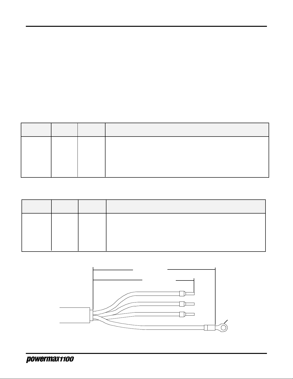
POWER CORDS - 208/240/480V, 200/230/400V and 600V POWER SUPPLIES
The 208/240/480V and 200/230/400V power supplies are shipped without a power cord. Use the tables
below to choose the proper wire size for the appropriate length cord. In the U.S., use a 3-conductor SO
type cord for single-phase, and a 4-conductor SO type cord for three-phase power supplies. In other
countries, use cords that are certified by local or national codes. Strip the power cord wires as shown in
Fig. 3-6. Cap or tin the conductor leads and use a #10 terminal on the ground wire. The cord should be
installed only by a licensed electrician.
The 600V conversion kit comes with a 10 AWG 7 ft (2 m) power cord. If changing the cord length, use a
10 AWG power cord.
208/240/480V Power supplies
Input Phase Input Recommended Power Cord Wire Size (AWG)
Voltage Current < 10 ft 10 – 25 ft 25 – 50 ft 50 – 100 ft 100 – 150 ft
208 VAC 1 92A 4 4 4 2 2
240 VAC 1 80A 6 6 4 4 4
480 VAC 1 40A 8 8 8 8 6
208 VAC 3 53A 6 6 6 6 4
240 VAC 3 46A 8 8 8 6 6
480 VAC 3 23A 10 10 10 10 8
200/230/400V Power supplies
Input Phase Input Recommended Power Cord Wire Size (mm2)
Voltage Current < 3 m 3 – 7.5 m 7.5 – 15 m 15 – 30 m 30 – 45 m
200 VAC 1 96A 25 25 25 35 35
230 VAC 1 84A 25 25 25 25 35
400 VAC 1 48A 10 10 10 10 16
200 VAC 3 56A 10 10 16 16 16
230 VAC 3 49A 10 10 10 10 16
400 VAC 3 28A 4 4 4 6 6
7.5" (178 mm)
5" (140 mm)
L1
L2
L3
#10
Ground
Figure 3-6 Power Cord Stripping for 208/240/480V and 200/230/400V Power Supplies
Operator Manual
3-5
S
ETUP
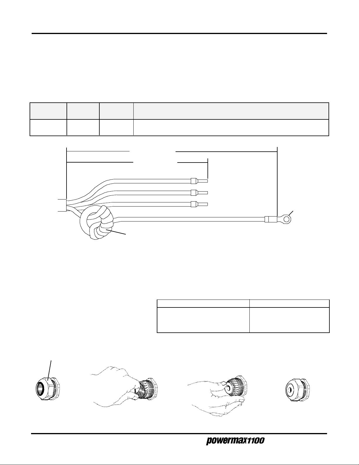
POWER CORDS - 230/400V CE POWER SUPPLIES
The 230/400V CE power supply is shipped with a power cord. If the three-phase power cord length
needs to be changed, use the table below to choose the proper wire size for the appropriate length.
Use a 4-conductor "HAR" type cord. Strip the power cord wires as shown in Fig. 3-7. Cap or tin
conductor leads and use a #10 terminal on the ground wire. The cord should be installed only by a
licensed electrician.
2
Input Phase Input Recommended Power Cord Wire Size (mm
Voltage Current < 3 m 3 – 7.5 m 7.5 – 15 m 15 – 30 m 30 – 45m
230 VAC 3 33A 4 4 6 6 6
400 VAC 3 19A 4 4 4 4 4
7.5" (178 mm)
5" (140 mm)
L1
L2
)
L3
#10
Ground
Wind the ground wire 8 turns around the toroid
Figure 3-7 Power Cord Stripping 230/400V CE Power Supplies
CHANGING THE STRAIN RELIEF SLEEVE
Depending on the diameter of the power cord you choose, the rear panel strain relief sleeve may need
to be changed. Alternate sleeves are located on the floor of the power supply behind the rear panel.
To choose the correct sleeve, either push
the power cord through the smallest
sleeve that it will go through, or measure
the power cord diameter and use the
adjacent table.
To change a sleeve:
1. Remove strain
relief cap
2. Remove strain
relief sleeve
Power Cord Diameter Use
Over 7/8" (22mm) Largest sleeve
3/4" to 7/8" (19mm to 22mm) Second largest sleeve
Under 3/4" (19mm) Smallest sleeve
3. Install new strain
relief sleeve and press
it into place
4. Replace strain relief
cap - After installing
power cord, tighten
cap.
3-6
Figure 3-8 Changing a Power Cord Strain Relief Insert
Operator Manual
S
ETUP
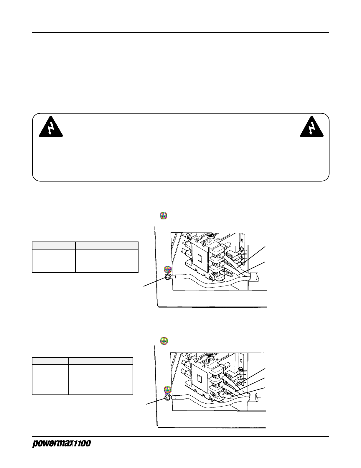
SINGLE-PHASE AND THREE-PHASE POWER CONFIGURATIONS
All Powermax1100 power supplies except the 230/400V CE and 600V power supplies can operate from
either a single-phase or three-phase input. The 230/400V CE and 600V power supplies operate only
from a three-phase input.
Power cords must meet the specifications described earlier in this section. Follow applicable local or
national wire color conventions. See also EMC Compatibility and
CE compliance recommendations.
WARNING
SHOCK HAZARD: Always turn off the power, unplug the cord and wait 5 minutes before
removing any power supply cover. If the power supply is directly connected to a line
disconnect switch, place switch in the OFF position. In the U.S., use a "lock-out / tag-out"
procedure until the service or maintenance work is complete. In other countries, follow
appropriate local or national safety procedures.
Single-Phase
Mains Supply
on page i for further
Remove the rear panel (Fig. 3-2) and connect the power cable to contactor as shown in Fig. 3-9.
Connect the ground wire to the stud marked .
Conductor Color
Line (U) Black or Brown
Neutral/Line (V)White or Blue
Ground Green or Green/Yellow
Green
Black
White
Figure 3-9
Single-Phase Power
Three-Phase
Remove the rear panel (Fig. 3-2) and connect the power cable to the contactor as shown in Fig. 3-10.
Connect the ground wire to the stud marked .
Conductor Color
L1 (U) Brown or Black
L2 (V) Blue or White
L3 (W) Black or Red
Ground Green/Yellow or Green
Brown
Blue
Black
Green/
Yellow
Operator Manual
Figure 3-10
Three-Phase Power
3-7

S
ETUP
POWER CORD PLUGS
The user must obtain a power cord plug that is certified by national or local electrical codes. The plug
should be connected to the power cord by a licensed electrician.
POWER REQUIREMENTS
Line Voltage Disconnect Box
Use a separate line disconnect box for each power supply. This disconnect box allows the operator to
turn the power supply off quickly in an emergency situation. The switch should be located near the
power supply, and should be easily accessible to the operator. The interrupt level of the switch must be
equal to or exceed the continuous rating of the fuses. Use slow-blow fuses according to the power
requirements listed below.
Input Input Current Recommended
Voltage Phase @ 11.2 kw Output Slow-Blow Fuse Size
200 VAC 1 96 amps 125 amp
208 VAC 1 92 amps 125 amp
230 VAC 1 84 amps 110 amp
240 VAC 1 80 amps 110 amp
400 VAC 1 48 amps 70 amp
480 VAC 1 40 amps 60 amp
200 VAC 3 56 amps 80 amp
208 VAC 3 53 amps 70 amp
230 VAC 3 49 amps 70 amp
230 VAC CE 3 33 amps 40 amp
240 VAC 3 46 amps 60 amp
400 VAC 3 28 amps 35 amp
400 VAC CE 3 19 amps 30 amp
480 VAC 3 23 amps 30 amp
600 VAC 3 20 amps 30 amp
GROUNDING REQUIREMENTS
To ensure personal safety, proper operation, and to reduce electromagnetic interference (EMI), the
Powermax1100 must be properly grounded through the power cord according to your local or national
electrical codes.
The power supply chassis is electrically conductive and can present a shock hazard if it is not properly
grounded through the line voltage disconnect box. Single-phase service must be of the 3-wire type with
a green or green/yellow wire for protective earth ground. It must comply with local electrical
requirements. Do not use a 2-wire service! Refer to
service must be of the 4-wire type with a green/yellow wire for protective earth ground.
Grounding
, in the Safety section. Three-phase
3-8
Operator Manual
S
ETUP
Figure 3-11 Proper Work Clamp Connection
WORK CABLE AND CLAMP
The work clamp must be attached to the workpiece when plasma cutting. Ensure that the work clamp
and the workpiece make good metal-to-metal contact. Attach the work clamp as close as possible to
the area being cut to reduce exposure to electric and magnetic fields (EMF). Do not attach the work
clamp to the portion of the workpiece to be cut away.
GAS SUPPLY REQUIREMENTS
The gas supply for the Powermax1100 can be either air or nitrogen. Air can be supplied as shop
compressed air or cylinder compressed air. Nitrogen can be supplied from compressed gas cylinders
or liquid containers. A high-pressure regulator on either type of supply must be used and must be
capable of delivering the following:
400 scfh/6.7 scfm (189 l/min) at a pressure of 90 psi (6.2 bar) to the filter on
the power supply.
The filter location is shown in Fig. 3-13.
WARNING
Do not allow the gas inlet pressure to the filter on the power supply to exceed 120 psi (8.2
bar). The plastic filter bowl is rated for 150 psi (10.3 bar) and may explode if this pressure
is exceeded. See the label on the filter bowl for other safety warnings.
Air Supply Quality
The cylinder or shop compressed air supply must be clean, dry and oil-free. If air supply quality is poor,
cut speeds decrease, cut quality deteriorates, cutting thickness capability decreases, and parts life
shortens.
Operator Manual
3-9
S
ETUP
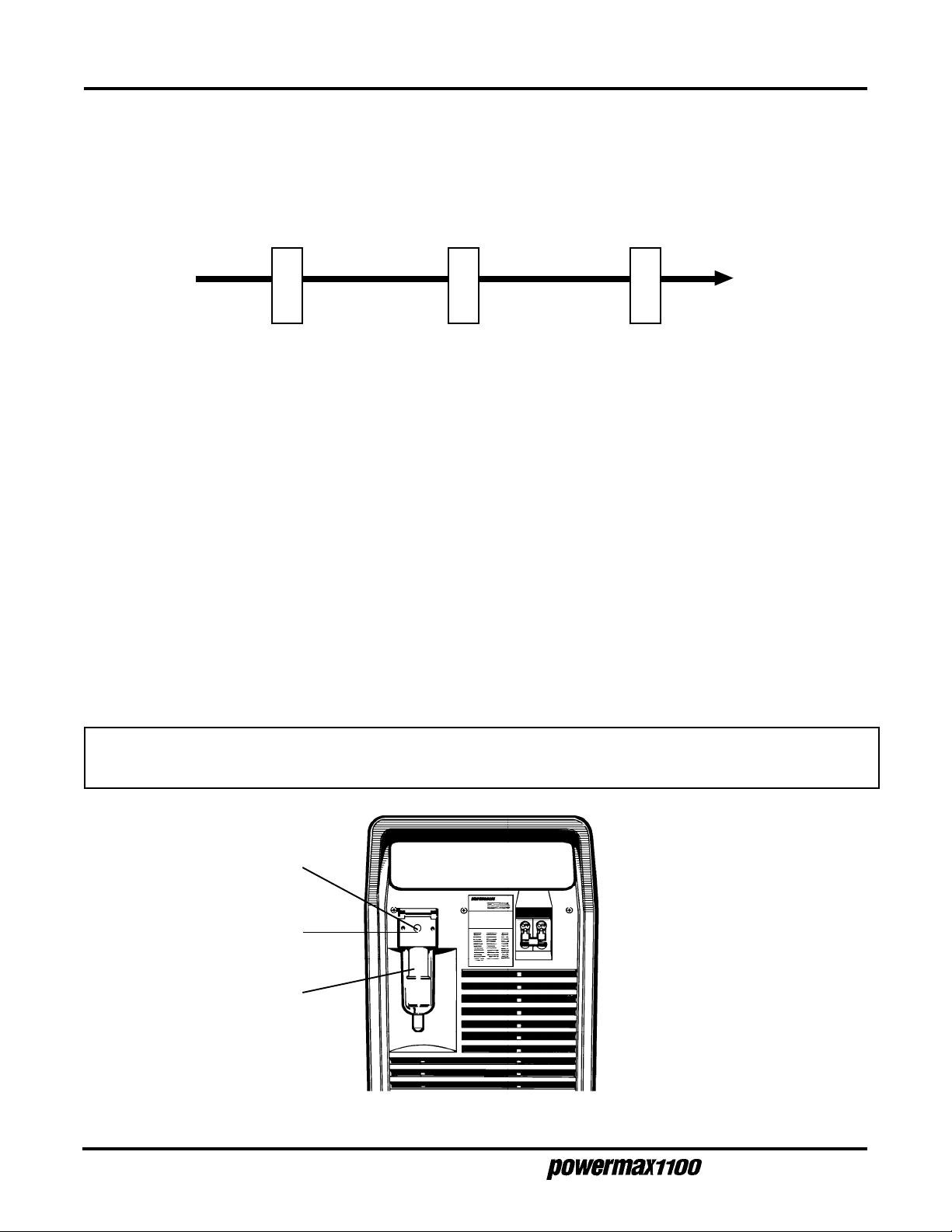
Additional Air Filtration
Use a three-stage coalescing filtration system as shown in Fig. 3-12 when site conditions introduce
moisture, oil or other contaminants into the air line.
Water/particle filter Oil filter Oil vapor filter
From air
supply
Figure 3-12 Recommended Three-Stage Air Filtration System
To
Powermax1100
Nitrogen Supply Quality
Nitrogen must be supplied to the Powermax1100 at 99.995% purity. If the purity level of the nitrogen is
too low, cut speeds decrease, cut quality deteriorates, cutting thickness capability decreases, and parts
life shortens. (Note: These conditions also occur if there are leaks in the gas supply hoses or
connections.) The nitrogen supply can be compressed gas cylinders or liquid containers.
GAS SUPPLY CONNECTION
Use a 3/8 inch (9.5 mm) ID inert gas hose to connect the gas supply (air or nitrogen) to the power
supply filter. To connect the hose, install a 1/4 NPT nipple to the filter block as shown in Fig. 3-13.
Apply liquid pipe sealant to the threads to ensure a leak-free installation. A nipple and adapters are
included in the consumable parts kit.
CAUTION: Never use 37)( tape when installing the nipple or adapters. Bits of tape can break off
and enter the air line and harm the pressure regulator, pressure switch and valve.
1/4 NPT Nipple
Gas Supply
Hose Connection
Filter
Figure 3-13 Rear Panel, Gas Supply Connection to Filter
3-10
Operator Manual

TORCH LEAD CONNECTION
To connect the torch lead to the power supply:
1. Align the connector key plug on the torch lead with the connector receptacle key slot on the
power supply and push in until the pins seat. The top of the torch connector is marked "TOP".
2. Before tightening, turn the connector securing ring 1/4 turn to the left to ensure that the securing
ring threads and the connector receptacle threads are aligned.
3. Turn the securing ring to the right to tighten.
PAC135M ON/OFF Pendant Connection
WARNING
Do not connect the cutting machine interface START signal if using the
ON/OFF pendant! (See page 3-12)
S
ETUP
To connect the on/off pendant lead to the PAC135M machine torch pigtail:
1. Align the pendant lead connector key plug with the connector receptacle key slot on the pigtail
and push in until the pins seat.
2. Turn the connector securing ring to the right to tighten.
PAC135M Torch ON/OFF Switch Connection Data
The PAC135M torch lead is supplied with a pigtail so that the on/off pendant may be used. If you want
to use a different on/off switch configuration, note that the wiring configuration to the 3-socket female
receptacle on the pigtail is as follows:
Socket A White Wire
Socket B Not Used
Socket C Black Wire
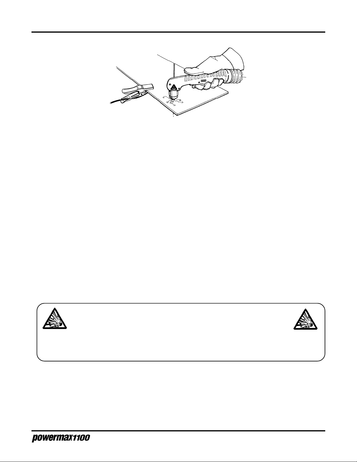
PAC135M Torch Alignment
Make sure that the machine torch is mounted at right angles to the workpiece in order to get a vertical
cut. Use a square to align the torch at 0° and 90° as shown in Fig. 3-14.
Operator Manual
3-11

S
ETUP
Torch - (typical)
0°
90°
Figure 3-14 Aligning the Machine Torch with Square
MACHINE INTERFACE WITH PAC135M
Signals for arc transfer, start, and arc voltage are available on power supplies that have the machine
interface option.
WARNING
Do not connect the cutting machine interface START signal if using an ON/OFF pendant!
• Plug the machine interface cable into the connector on the rear panel and connect the machine
interface cable to the cutting machine.
Green
Black
Red
Black
Signal:
Type:
Notes:
Rear panel
sockets
Cable wires
START (start plasma)
Input
Normally open. 24 VAC open circuit voltage
at START terminals.
Requires dry contact closure to activate.
3, 4
Green, Black
XFER (start machine motion)
Output
Normally open. Dry contact closure when arc
transfers. 120 VAC maximum at machine
interface relay or switching device.
12, 14
Red, Black
3-12
Figure 3-15 Machine Interface Cable 023206 and Signals
Operator Manual

S
ETUP
Arc Voltage
If arc voltage is necessary for activating a torch height control, the customer must supply an 18 AWG,
single pair, unshielded cable rated for 300V or greater. The arc voltage signal should be connected
only by qualified service personnel.
WARNING
SHOCK HAZARD: Always turn off the power, unplug the cord and wait 5 minutes before
removing any power supply cover. If the power supply is directly connected to a line
disconnect switch, place switch in the OFF position. In the U.S., use a "lock-out / tag-out"
procedure until the service or maintenance work is complete. In other countries, follow
appropriate local or national safety procedures.
1. Disconnect power from Powermax1100.
2. Remove the screws that attach Powermax1100 cover to the chassis. Remove the cover.
3. Push the cable through the strain relief at the rear of Powermax1100.
Strain Relief - arc voltage cable
Figure 3-16 Location of Arc Voltage Cable Strain Relief
4. Route the cable to the machine interface board located on the top of the power supply near the
Powermax1100 control board. Connect the arc voltage cable as shown in Fig. 3-17. Tighten the
strain relief.
J1
1
6
8
START
XFER
ARC
VOLTAGE
Signal:
Type:
Notes:
J1-6
J1-8
ARC VOLTAGE (torch height control)
Output
Full arc voltage. No voltage divider.
300 VDC maximum.
(Signal not available on rear panel
connector.)
+VDC
-VDC
Figure 3-17 Machine Interface Board Connections for Arc Voltage
Operator Manual
3-13

Section 4 OPERATION
In this section:
O
PERATION
Controls and Indicators ................................................................................... 4-2
Operating Instructions ..................................................................................... 4-3
Pilot Arc Controller (Optional)..................................................................... 4-4
P AC135T Safety T rigger Operation............................................................. 4-5
Operating Tips................................................................................................. 4-6
Changing Consumable Parts...................................................................... 4-6
Cutting ........................................................................................................ 4-8
Piercing..................................................................................................... 4-10
Gouging .....................................................................................................4-11
Cut Chart - 80A Standard Consumables....................................................... 4-12
Cut Chart - 40A Consumables ...................................................................... 4-13
Common Cutting Faults ................................................................................ 4-14
Operator Manual
4-1

O
PERATION
CONTROLS AND INDICAT ORS
• Green POWER ON LED
When illuminated, indicates that all control circuits are activated, the torch safety interlock is
satisfied and the system is ready for operation.
• Yellow LINE VOLTAGE LED
When illuminated, indicates that the AC line voltage is below proper operating limits.
• Yellow TEMP LED
When illuminated, indicates that the power supply temperature has exceeded operating limits.
• Green GAS PRESSURE LED
When illuminated, indicates that the gas pressure is within operating limits.
• GAS TEST Switch
When pushed in, allows the operator to adjust the pressure setting.
• AMPS Output Adjustment Knob
Adjusts output current between 30 and 80 amps.
• Pressure Regulator
Regulates input gas pressure to the power supply.
• Pressure Gauge
Indicates gas pressure at the power supply.
• ON (I)/OFF (0) Power Switch
Activates the power supply and its control circuits.
GAS
TEST
POWER
ON
LINE
VOLTAGE
TEMP
GAS
PRESSURE
ON (I)/OFF (0) Power Switch
AMPS
4-2
4-2
Pressure Gauge Pressure Regulator
Figure 4-1 Powermax1100 Controls and Indicators
Operator Manual
Operator Manual

O
PERATION
OPERATING INSTRUCTIONS
WARNING
Before operating this system, read the Safety section of this manual thoroughly!
1. Ensure that the work environment and your clothing meet the safety requirements outlined in
the Safety section.
2. Follow the instructions in the Setup section. Verify that the input gas supply pressure is set to
90 psi (6.2 bar).
3. At the rear of the power supply, set the power switch to the ON (I) position. The POWER ON
and GAS PRESSURE LEDs should illuminate. The LINE VOLTAGE LED will blink and then
extinguish. The TEMP LED will remain extinguished.
GAS PRESSURE
POWER ON
PRESSURE GAUGE
Figure 4-2 Powermax1100 Operating Indicators and Adjustments
4. Adjust the gas pressure REGULATOR to 65 psi (4.5 bar):
• Pull the REGULATOR CAP out
• Push the GAS TEST switch in
• Turn the REGULATOR CAP while still pushing in the GAS TEST switch
• After adjusting to 65 psi (4.5 bar), release the GAS TEST switch
• Push the REGULATOR CAP back in
GAS TEST
AMPS
REGULATOR
REGULATOR
CAP
Note: If using 50 ft (15.2 m) torch leads, adjust the pressure to 70 psi (4.8 bar).
5. Adjust the AMPS knob to the desired setting. See
Cut Chart
later in this section if necessary.
Operator Manual
4-3

O
PERATION
6. Attach the work clamp securely to the workpiece. Do not attach it to the portion that will fall
away.
Figure 4-3 Proper Work Clamp Connection
WARNING
The PAC135 torches are contact-start torches that produce a plasma arc immediately after the torch start switch closes. Always hold the hand torch away from
your body as a precaution against accidental torch firing. Be aware of this hazardous potential. Failure to do so can result in serious bodily injury.
7. The Powermax1100 is now ready to operate. When you are ready to cut, place the tip of the
torch at the edge of the workpiece. Pull back on the trigger switch to start the arc. See
PAC135T Safety Trigger Operation
To begin cutting from within the workpiece see
8. As the torch moves across the workpiece, the arc will transfer from the torch to the workpiece.
Move the torch in the desired direction, at a speed which will ensure good cut quality. When
using shielded consumables, drag the torch tip directly on the workpiece. See
and
Cut Charts
9. When the cut is finished, release the torch switch to extinguish the arc. The arc will also extinguish when transfer to the workpiece is no longer sensed.
later in this section.
later in this section for proper operation of the safety trigger.
Piercing
later in this section.
Operating Tips
Pilot Arc Controller (Optional)
In power supplies with the pilot arc controller option, the torch will return to a pilot arc after finishing a
cut if the torch switch remains pressed. After 5 seconds, the pilot arc will then extinguish if no arc
transfer is sensed. The pilot arc controller option is especially useful if you are cutting expanded metal.
See
Powermax1100 Field Upgrade Kits and Optional Parts
4-4
in Section 5 for part number information.
Operator Manual

PAC135T Safety Trigger Operation
Safety On position. In this position
1
the trigger cannot be pulled
back, so that the torch cannot
be accidentally fired.
O
PERATION
Start pushing the safety forward.
2
Do not pull back on the trigger now;
wait until the safety reaches the
Safety Off position as shown in step 3.
Safety Off position. In this position,
3
the trigger can be pulled back so that
the torch can be fired.
Release the safety to return to the
4
Safety On position as shown in step 1.
Figure 4-4 PAC135T Torch Safety Trigger Operation
Operator Manual
4-5

O
PERATION
OPERATING TIPS
Changing Consumable Parts
WARNING
SHOCK HAZARD: Always turn off power and unplug cord from wall before changing
consumable parts. If power supply is directly connected to a line disconnect switch, place line
disconnect switch to OFF position. Do not rely on the cap-on sensor circuit to remove power.
It is provided strictly for safety backup.
In the U.S., use a "lock-out / tag-out" procedure until the service or maintenance work is
complete. In other countries, follow appropriate local or national safety procedures.
1. Unscrew the retaining cap. The nozzle will be released when the retaining cap is removed.
2. Check the shield for external signs of wear. The shield should be clean and clear of metal
debris. The gas holes along the edge of the shield should not be blocked with debris. The
center hole should not have any nicks or gouges, and should show no signs of arcing activity.
3. Unscrew the shield from the retaining cap. Inspect the gas holes from the inside. The holes
should be clear of metal debris. If the gas holes are blocked by debris, try to open them by
pushing a pin through each one from the outside of the shield to the inside. If the shield is still
good, screw it back on to the retaining cap. If it is damaged, replace it with a new one.
4. Inspect the nozzle for damage or wear. If the hole in the nozzle is worn or oval-shaped, replace
the nozzle.
5. Using the electrode wrench supplied in the consumable parts kit, unscrew the electrode from
the torch body. The swirl ring will be released when the electrode is removed.
6. Inspect the electrode. If the center of the electrode has a pit more than 1/16 inch (1.6 mm)
deep, replace it.
7. Inspect the swirl ring. It should be clean, and the holes along the side should not be plugged. If
the swirl ring is damaged, replace it.
8. Inspect the O-ring on the torch. It should be lubricated and undamaged. If it is dry, lubricate it
with a thin film of the lubricant provided in the consumable parts kit. If it is damaged, replace it.
9. Replace the consumable parts as shown in Fig. 4-5.
10. When the retaining cap is tightened, the circuit between the pin contacts located on the torch
head will close, indicating that the torch is again ready for operation. Plug the power cord back
in, or place the line disconnect switch to the ON position.
4-6
Operator Manual

Shielded - 80A, 40A
Machine Shield
120516
Retaining Cap
120483 - 80A
Nozzle
120476 - 80A
O
PERATION
Hand Shield
120475
Extended
Deflector
120519
Gouging
Shield
120510
Retaining Cap
120520 - 40A
Retaining Cap
120483
Retaining Cap
120483
Nozzle
120515 - 40A
Nozzle
120518
Nozzle
120509
Electrode
120473
Electrode
120517
Electrode
120473
Swirl Ring
120474
PAC135T
Torch
O-Ring
026020
Figure 4-5 Consumables
Description of Consumables
• Shielded 80A For cutting above 40A. Shielded nozzle allows the torch tip to be dragged directly on the
workpiece.
• Shielded 40A For optimal cutting on thinner materials at or below 40A.
• Extended For increased visibility and access for special applications. The nozzle is not shielded.
Maintain a standoff distance from the workpiece of approximately 1/8" (3 mm) when
cutting above 40A to avoid accelerated consumable parts wear. Use only with the
machine torch in CE countries.
• Gouging For metal removal without cutting. Use for weld removal or setup. Nozzle shield may be
placed directly on the workpiece.
Operator Manual
4-7
1-98
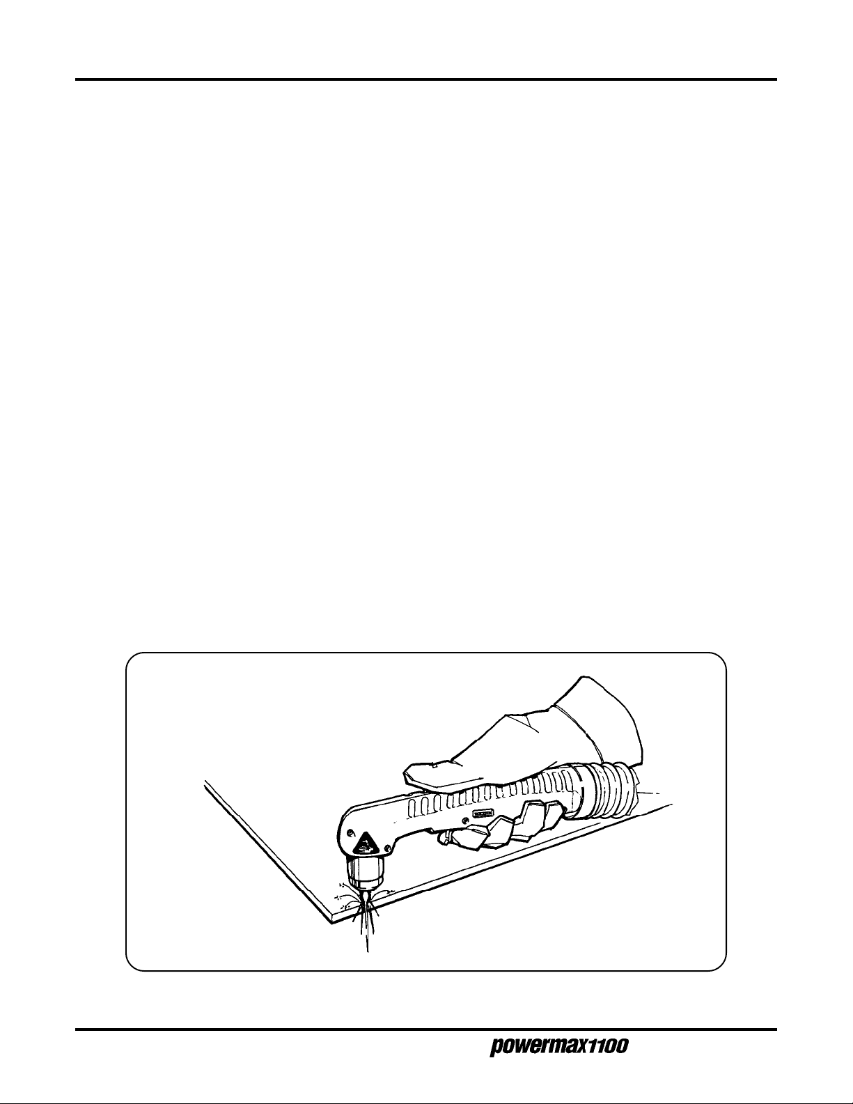
O
PERATION
Cutting
• Do not fire the pilot arc into the air needlessly—doing so causes a significant reduction of the
nozzle and electrode life.
• If arc transfer to the workpiece does not occur within 5 seconds, the pilot arc will shut off. Release the torch trigger and press it again to reset the pilot arc timer.
• Start cutting from the edge of the workpiece (Fig. 4-6). To penetrate fully and cut cleanly
through the workpiece, pause momentarily at the beginning and at the end of each cut.
• When cutting, make sure that the sparks are coming out of the bottom of the workpiece. If they
are spraying on top of the workpiece, you are moving the torch too fast, or you do not have
sufficient power to fully penetrate the workpiece.
• Hold the torch lightly on the metal (if using shielded consumables) or just above the metal.
Holding the torch firmly to the workpiece causes the shield to stick and makes smooth cutting
difficult. The arc transfers to the workpiece once the torch is within 1/8 inch (3 mm) of the
workpiece.
• Pulling the torch through the cut is easier than pushing it.
• Hold the torch nozzle at a vertical position and watch the arc as it cuts along the line (Fig. 4-8).
By lightly dragging the shield on the workpiece, you can maintain a steady cut. For straight-line
cuts, use any straight edge as a guide.
• When cutting thin material, reduce the amps until you get the best quality cut.
• To cut circles, use a template or a radius cutter attachment (Fig. 4-7).
4-8
Figure 4-6 Starting a Cut
Operator Manual
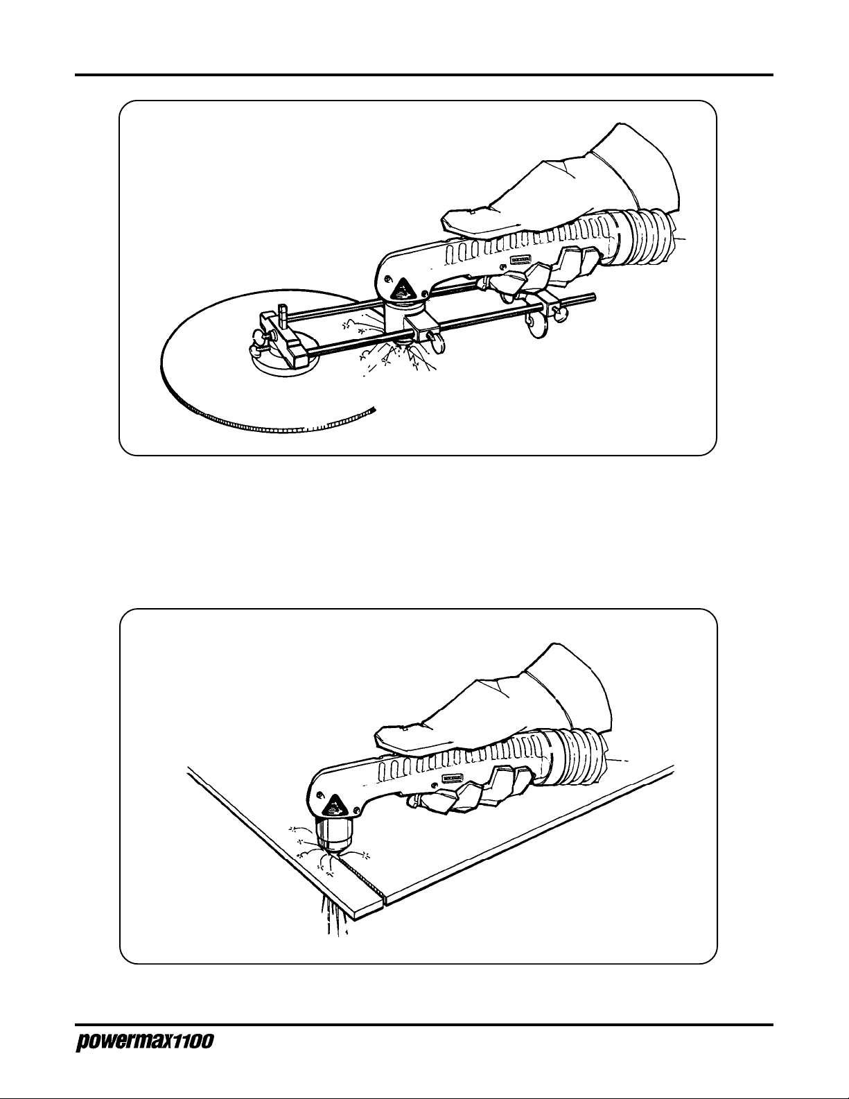
O
PERATION
Figure 4-7 Cutting a Circle
Figure 4-8 Dragging the Torch
Operator Manual
4-9

O
PERATION
Piercing
• Hold the torch so that the tip is approximately 1/16 inch (1.6 mm) away from the workpiece
before firing the torch. This method maximizes the life of the nozzle.
• Hold the torch at an angle to the workpiece away from yourself, pull back on the trigger and
slowly rotate the torch to an upright position. This is particularly important when cutting thicker
material. Make sure that the torch is pointed away from you and the people near you to avoid
any danger from sparks and hot metal.
• When the pierce is complete, bring the torch head to a perpendicular position and proceed with
the cut.
4-10
1. Tilt the torch and press the start button.
2. Rotate the torch to an upright position.
Figure 4-9 Piercing
Operator Manual
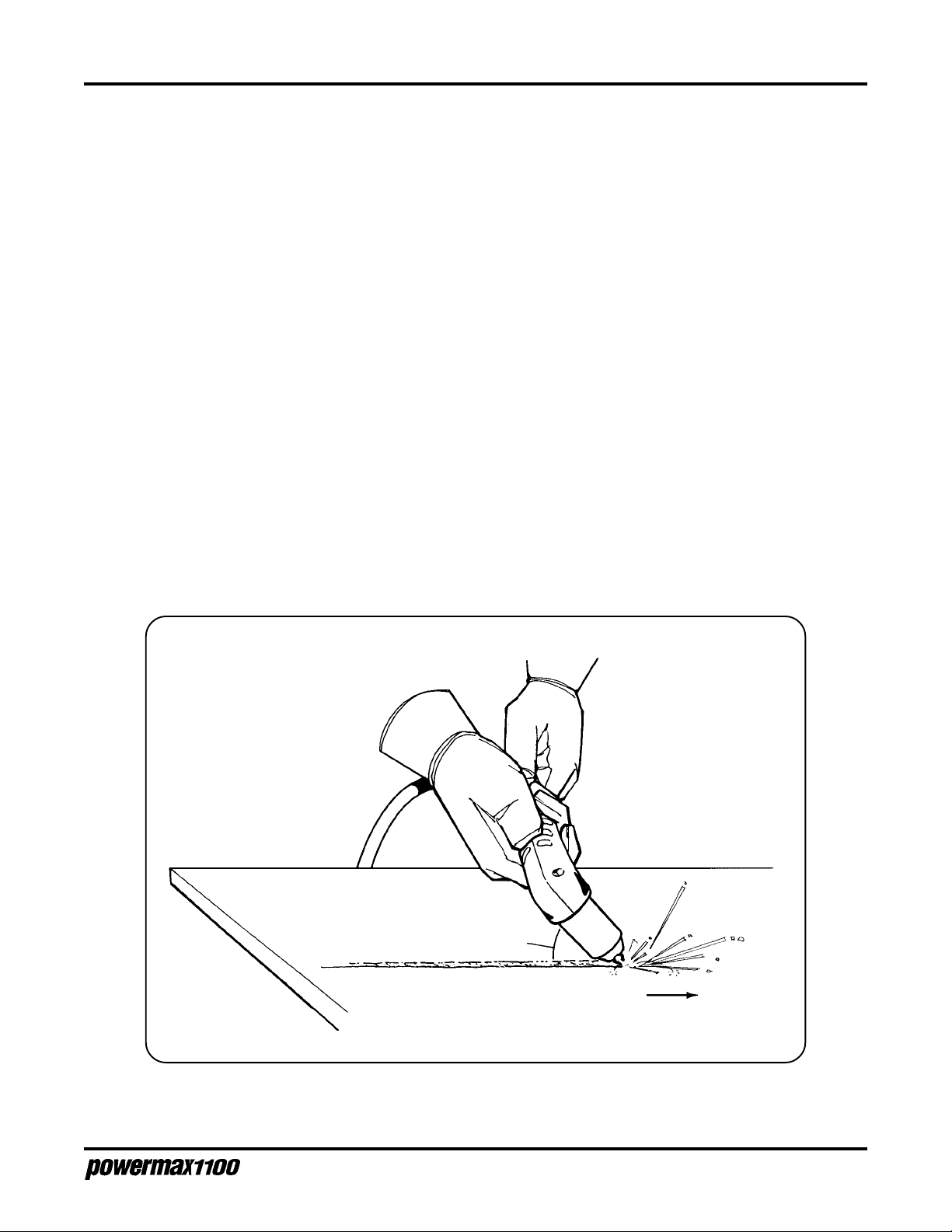
O
PERATION
Gouging
The Powermax1100 can be used for gouging mild steel by using the optional gouging nozzle and
gouging shield.
• Always wear full protection:
- A welding helmet with at least a #8 lens shade – Hypertherm recommends using a #10 lens
shade when gouging
- Welding gloves
- A welding jacket
The arc is fully exposed and will cause serious burns if the skin is not covered.
• Install the gouging nozzle and shield the same as a standard cutting nozzle and shield. See
Changing Consumable Parts
• Adjust the air pressure to 60–65 psi (4.1–4.5 bar) with air flowing from the torch. Note that this
is lower than the cutting pressure.
• Tilt the torch approximately 45° from the surface to be gouged and push the torch in the desired
direction. Multiple passes or "wearing" may be necessary to gouge wider and deeper sections.
earlier in this section.
Operator Manual
45°
Direction of travel
Figure 4-10 Gouging
4-11
3-98
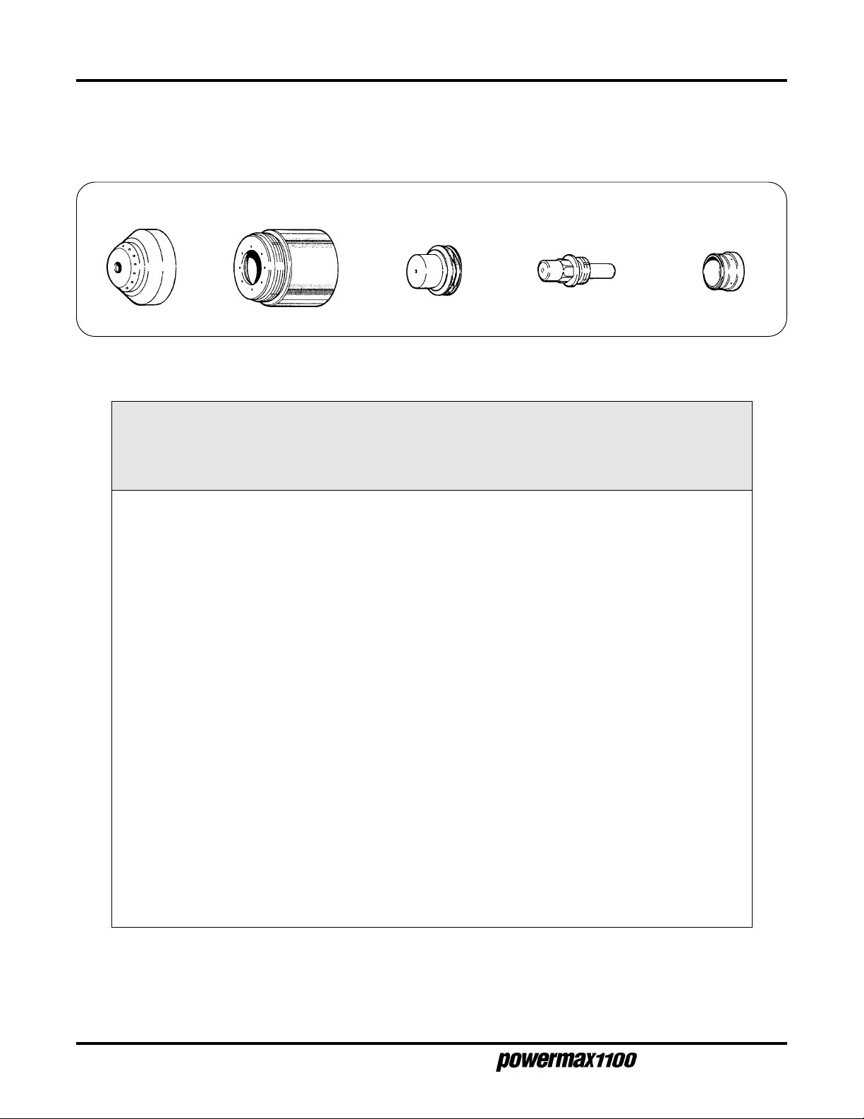
O
PERATION
CUT CHART - 80A STANDARD CONSUMABLES
The following recommended settings are for mechanized cutting. Torch-to-work distance is 1/16 inch
(1.6 mm) for all cuts.
Shield
120516
Material Arc Arc Travel Pierce
Thickness Material Current Voltage Speed* Delay
(in.) (mm) (A) (V) (ipm) (mm/min ) (S)
3/16" 4.8 Mild steel 80 115 160 4060 0
1/4" 6.4 Mild steel 80 117 110 2800 0.25
3/8" 9.5 Mild steel 80 116 57 1450 0.50
1/2" 12.7 Mild steel 80 120 38 965 0.75
5/8" 15.9 Mild steel 80 124 25 635 1.75
3/4" 19.0 Mild steel 80 124 20 510 n/a
7/8" 22.2 Mild steel 80 132 14 355 n/a
1" 25.4 Mild steel 80 133 11 280 n/a
Retaining Cap
120483 - 80A
Nozzle
120476 - 80A
Recommended
Electrode
120473
Swirl Ring
120474
3/16" 4.8 Stainless Steel 80 120 160 4060 0.25
1/4" 6.4 Stainless Steel 80 121 100 2540 0.50
3/8" 9.5 Stainless Steel 80 122 53 1345 1.00
1/2" 12.7 Stainless Steel 80 123 32 810 1.25
5/8" 15.9 Stainless Steel 80 123 25 635 1.75
3/4" 19.0 Stainless Steel 80 126 18 460 n/a
1" 25.4 Stainless Steel 80 133 10 255 n/a
1/8" 3.2 Aluminum 80 119 340 8640 0
1/4" 6.4 Aluminum 80 120 140 3560 0.25
3/8" 9.5 Aluminum 80 122 90 2285 0.50
1/2" 12.7 Aluminum 80 129 60 1525 1.00
3/4" 19.0 Aluminum 80 131 31 790 n/a
* Recommended travel speeds are 10–20% slower than maximum. These slower speeds will produce optimum
cut quality.
4-12
Operator Manual
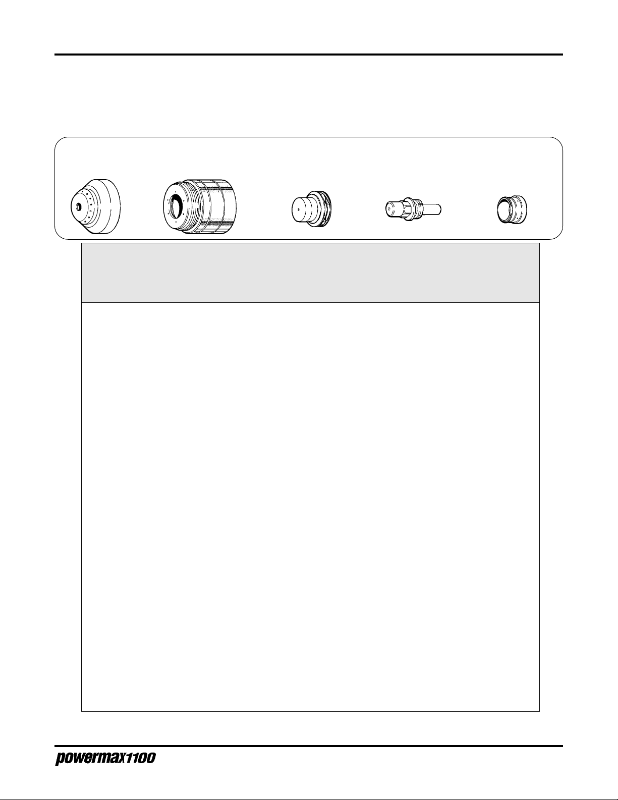
O
PERATION
CUT CHART - 40A CONSUMABLES
Use 40-amp consumables on thin material to obtain a narrower kerf width and to minimize the heataffected zone. The following recommended settings are for mechanized cutting. Torch-to-work
distance is 1/16 inch (1.6 mm) for all cuts.
Shield
120516
Material Arc Arc Travel Pierce
Thickness Material Current Voltage Speed* Delay
(ga. or in.) (mm) (A) (V) (ipm) (mm/min ) (S)
26 ga. 0.5 Mild steel 30 116 510 12950 0
22 ga. 0.8 Mild steel 30 116 360 9140 0
20 ga. 0.9 Mild steel 30 116 240 6100 0
18 ga. 1.2 Mild steel 30 118 210 5330 0
16 ga. 1.5 Mild steel 30 118 120 2050 0
14 ga. 1.9 Mild steel 40 117 200 5080 0.25
10 ga. 3.4 Mild steel 40 121 100 2540 0.50
3/16" 4.8 Mild steel 40 116 70 1780 1.00
1/4" 6.4 Mild steel 40 119 42 1070 1.25
3/8" 9.5 Mild steel 40 126 19 480 n/a
1/2" 12.7 Mild steel 40 131 14 355 n/a
Retaining Cap
120520 - 40A
Nozzle
120515 - 40A
Electrode
120473
Recommended
Swirl Ring
120474
26 ga. 0.5 Stainless steel 30 116 520 13200 0
22 ga. 0.8 Stainless steel 30 116 260 6600 0
20 ga. 0.9 Stainless steel 30 117 170 4320 0
18 ga. 1.2 Stainless steel 40 116 310 7870 0
16 ga. 1.5 Stainless steel 40 117 200 5080 0
14 ga. 1.9 Stainless steel 40 115 170 4320 0.25
10 ga. 3.4 Stainless steel 40 118 70 1780 0.50
3/16" 4.8 Stainless steel 40 119 48 1220 1.00
1/4" 6.4 Stainless steel 40 120 35 890 1.50
3/8" 9.5 Stainless steel 40 125 16 410 n/a
1/2" 12.7 Stainless steel 40 126 11 280 n/a
1/32" 0.8 Aluminum 30 117 600 15240 0
1/16" 1.6 Aluminum 30 117 240 6100 0
3/32" 2.4 Aluminum 40 117 250 6350 0.25
1/8" 3.2 Aluminum 40 117 170 4320 0.50
1/4" 6.4 Aluminum 40 122 53 1350 1.50
3/8" 9.5 Aluminum 40 132 28 710 n/a
* Recommended travel speeds are 10–20% slower than maximum. These slower speeds will produce optimum
cut quality.
Operator Manual
4-13

O
PERATION
Cut Chart Notes:
The cut charts are optimized to provide the best cut angle, least dross and best cut surface finish. Remember
that cut charts are intended to provide a good starting point for each cutting assignment. Every cutting
system requires "fine-tuning" each cutting set up to the materials on site, in order to obtain optimum cut
quality.
• Maximum recommended mechanized cutting capacity with 80A consumables: 1/2 inch
(12 mm) on mild steel, and 3/8 inch (9.5 mm) on stainless steel and aluminum.
• A manual machine motion signal must be given in mechanized applications when cutting material thinner
than 18 gauge (1.2 mm).
• See page 4-7 or Section 5 for additional consumable parts.
• Compressed air or nitrogen must be available to the power supply filter/pressure regulator at a flow rate of
400 scfh/6.7 scfm (189 l/min) at a pressure of 90 psi (6.2 bar). The dynamic (flowing) pressure when
operating is 65 psi (4.5 bar). If torch leads are 50 ft (15.2 m), the dynamic pressure when operating is 70
psi (4.8 bar). If the pressure to the power supply falls below 40 psi (2.8 bar), the torch will extinguish.
• After several minutes of running, the torch retaining cap may become hot. To cool it, push in and hold the
GAS TEST switch until the cap cools down.
• The duty cycle, or the amount of time the pilot or plasma arc can remain “on” in minutes within a 10minute period, is affected by many factors. When the current is set at 80 amps, the Powermax1100 has a
50% duty cycle at a temperature of 104° F (40° C). At these conditions, the plasma arc can remain on 5
minutes out of every 10 minutes without causing the temperature sensors to disable the unit. The duty
cycle increases to 100% at a temperature of 104° F (40° C) when the current is set below 57 amps.
• To avoid performance deterioration of the Powermax1100, input voltage should be within 10% of the
specified system line voltage setting.
• When using extended consumables, maintain a torch-to-work distance of approximately 1/8" (3 mm)
when cutting above 40A to avoid accelerated consumable parts wear. The torch will extinguish if the
nozzle is pressed back against the electrode.
COMMON CUTTING FAULTS
• If the workpiece is not totally penetrated,
- The current may be too low.
- The cut speed may be too high.
- The torch parts may be worn.
- The metal being cut may be too thick.
- The work clamp may not be properly attached to the workpiece.
• If dross forms on the bottom of the cut,
4-14
- The cutting speed may be too slow.
- The torch parts may be worn.
- The metal being cut may be too thick.
- The current may be too low.
Operator Manual

M
AINTENANCE/PARTS
Section 5 MAINTENANCE/PARTS
In this section:
Introduction ..................................................................................................... 5-2
Routine Maintenance ...................................................................................... 5-2
Bowl Draining and Filter Element Cleaning ................................................ 5-2
Removal, Cleaning and Replacement of the Cooling Air Filter................... 5-3
Basic Troubleshooting ..................................................................................... 5-4
Technical Questions ........................................................................................ 5-7
Parts................................................................................................................ 5-8
P AC135 Consumable Parts ........................................................................ 5-8
Consumable Parts Kits ............................................................................... 5-9
P AC135T Torch Assembly ........................................................................ 5-10
PAC135M Torch Assembly ........................................................................5-11
Powermax1100 Field Upgrade Kits and Optional Parts ........................... 5-12
Power Supplies - 208/240/480V.................................................................... 5-12
Power Supplies - 200/230/400V.................................................................... 5-12
Power Supplies - 230/400V CE..................................................................... 5-12
Operator Manual
5-1
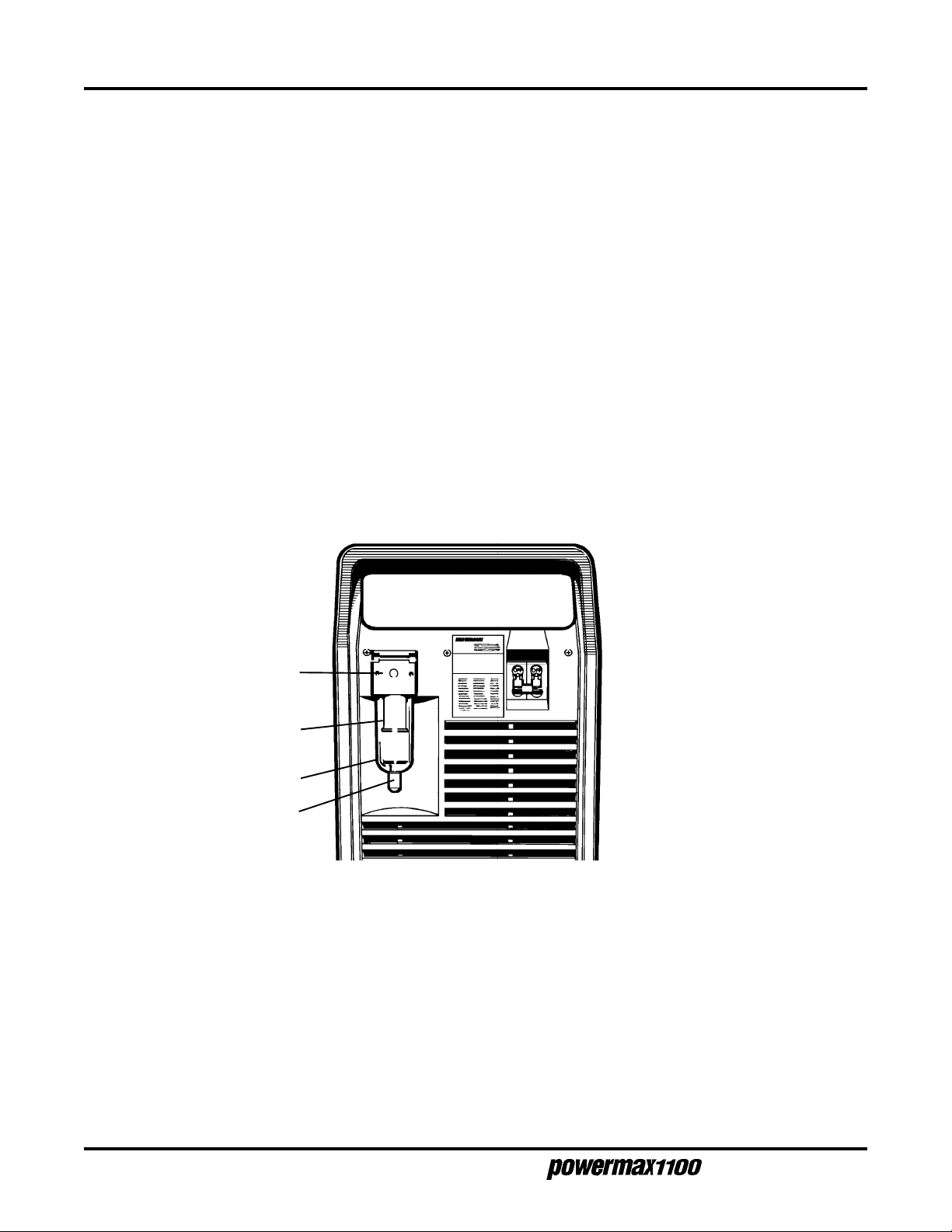
M
AINTENANCE/PARTS
INTRODUCTION
This section contains information for simple maintenance and troubleshooting. A brief parts list is also
included. For higher level troubleshooting, see
Technical Questions
later in this section.
ROUTINE MAINTENANCE
Bowl Draining and Filter Element Cleaning
Moisture in the torch can cause the torch to sputter and hiss. If moisture is present, purge the gas
lines. If moisture builds up in the bowl of the filter, drain the bowl and clean the filter element:
1. Shut off the gas supply and disconnect the gas supply hose from the filter assembly before
proceeding.
2. Remove the cap at the bottom of the filter bowl and turn the knurled drain valve to the right to
release water from the bowl.
Gas supply hose
connection
Filter element
Filter Bowl
Cap
Figure 5-1 Filter Assembly
3. Unscrew the filter bowl.
4. Unscrew the filter element.
5. Clean the filter element with alcohol, then blow it out with air.
Clean the bowl with household soap only.
6. Replace the filter element and filter bowl.
7. Reconnect the gas supply hose.
5-2
Operator Manual

M
AINTENANCE/PARTS
Removal, Cleaning and Replacement of the Cooling Air Filter
Powermax1100 systems are normally shipped without an air filter. If your Powermax1100 has the air
filter option, the filter will need cleaning periodically. Excessively dirty or dusty environments can block
the filter (if installed) and cause the power supply to overheat and shut down.
WARNING
SHOCK HAZARD: Always turn off the power, unplug the cord and wait 5 minutes before
removing any power supply cover. If the power supply is directly connected to a line
disconnect switch, place switch in the OFF position. In the U.S., use a "lock-out / tag-out"
procedure until the service or maintenance work is complete. In other countries, follow
appropriate local or national safety procedures.
1. Turn the Powermax1100 power switch to the OFF (0) position, unplug the power cord, or
turn off the wall receptacle, and disconnect the gas supply.
2. Remove the screws that secure the power supply cover to the chassis.
3. Remove the cover, and remove the cooling air filter from the clips by sliding the filter to the left
and then up.
Figure 5-2 Air Filter Removal
4. Clean the air filter with either soap and water or with low-pressure compressed air.
5. Replace the dry filter in the power unit with the wire mesh facing the fan.
6. Replace and refasten the power supply cover's screws.
Operator Manual
5-3

M
AINTENANCE/PARTS
BASIC TROUBLESHOOTING
LINE
VOLTAGE
POWER
ON
TEMP
GAS
PRESSURE
Problem
1. The ON/OFF power switch is set to I (ON),
but the fan does not operate and the
POWER ON LED is not illuminated.
ON/OFF
Power Switch
Cause
/ Solution
1.1 The power cord is not plugged into the
power receptacle.
Plug in the power supply.
1.2 The disconnect power switch is not set to
ON or there is no power available to the
disconnect power switch box.
Turn the power ON at the main power panel
or at the disconnect power switch box.
2. The POWER ON LED is illuminated but the
GAS PRESSURE LED is not illuminated.
3. The POWER ON LED is illuminated and the
LINE VOLTAGE LED is illuminated.
2.1 The gas supply is turned OFF or not
connected to the power supply.
Verify that the gas is turned on and
connected to the power supply.
2.2 Gas pressure is too low.
Set gas supply pressure to 90 psi (6.2 bar).
Verify that there are no leaks in the gas
supply line.
3.1 Power supply voltage links are incorrect.
See voltage configuration settings in
Section 3.
3.2 Line voltage is too low.
The following table represents the operating
range of the Powermax1100 power supplies.
Have an electrical technician check incoming
power.
5-4
Operator Manual

M
AINTENANCE/PARTS
Problem
4. The power supply shuts off immediately
after it is switched on.
Cause
Note: When the power supply operates at the
Lower Limit, the line voltage LED will illuminate
and the power supply will function with some
performance degradation. At -20% of the System
Line Voltage, the line voltage LED will illuminate
but the torch will not function. To avoid
performance deterioration, the input voltage
should be within +/-10% of the System Line
Voltage.
System
Lower Limit Line Voltage Upper Limit
170VAC 200VAC 235VAC
178VAC 208VAC 239VAC
195VAC 230VAC 270VAC
204VAC 240VAC 276VAC
340VAC 400VAC 470VAC
408VAC 480VAC 552VAC
510VAC 600VAC 690VAC
4.1 The retaining cap is loose.
Tighten the retaining cap.
/ Solution
5. The power supply shuts off approximately
5 seconds after it is switched on.
6. The fuse on the incoming power line fails
during cutting.
7. The POWER ON LED is illuminated, the
TEMP LED stays illuminated and the torch
will not fire.
4.2 The torch is defective.
See
Technical Questions
5.1 Power supply voltage links are incorrect.
See voltage configuration settings in
Section 3.
5.2 Line voltage is too high.
See the table above.
6.1 The power supply has exceeded the
capacity of the fuse.
Check the fuse for proper amperage rating.
See
Power Requirements
Check power cable for a short circuit or loose
connection.
7.1 One of the internal thermostat switches
has opened due to overheating.
Leave power supply on to allow the fan to
cool the power supply down, then shut the
power supply down and restart. Clean the
internal air filter (if installed). See
Cleaning and Replacement of the Cooling Air
Filter
earlier in this section.
on page 5-7.
in Section 3.
Removal,
Operator Manual
5-5

M
AINTENANCE/PARTS
Problem
8. The arc does not transfer after 5 seconds.
9. The arc blows out, but reignites when the
torch switch is depressed.
Cause
8.1 The 5-second time-out for the pilot arc
has occurred.
Press the torch start button again.
8.2 The work clamp is not connected or it is
broken.
Connect or repair the work clamp.
8.3 The work clamp is not making good metal-tometal contact.
Verify that the work clamp is properly attached to
the workpiece. Remove paint or any coating on
the workpiece before attempting to cut.
8.4 The workpiece is too far away from the torch.
Move the torch head closer (1/8 inch (3 mm)
maximum distance) to the workpiece and start
the torch again.
9.1 There are faulty consumable parts.
Inspect and change the consumable parts, if
necessary. See
/ Solution
Operating Tips
in Section 4.
10. The torch sputters and hisses.
9.2 The gas pressure is incorrect.
See
Operating Instructions
the gas pressure, if necessary.
9.3 The gas filter at the rear of the supply
contains excessive moisture.
Drain the filter bowl and clean the filter. See
Routine Maintenance
9.4 When using extended consumables, the
torch nozzle is being pressed against the
electrode.
Maintain a torch-to-work distance of
approximately 1/8" (3 mm) when using
extended consumables..
9.4 The torch is defective.
See
Technical Questions
10.1 The gas filter at the rear of the supply
contains excessive moisture.
Drain the filter bowl and clean the filter. See
Routine Maintenance
in Section 4 to adjust
earlier in this section.
on page 5-7.
earlier in this section.
5-6
Operator Manual

M
AINTENANCE/PARTS
Problem
11. The torch cuts poorly.
Cause
11.1 Power supply voltage links are incorrect.
See voltage configuration settings in
Section 3.
11.2 Torch consumables are worn.
See
Operating Tips
11.3
Line voltage is too low.
See Cause/Solution 3.2.
/ Solution
in Section 4.
TECHNICAL QUESTIONS
If you are unable to fix the problem with your Powermax1100 by following this basic troubleshooting
guide or if you need further assistance:
1. Call your distributor. He will be able to help you, or refer you to an authorized Hypertherm repair
facility.
2. Call the nearest Hypertherm office, listed in the front of this manual.
3. See the Powermax1100 service manual for wiring diagrams, higher level troubleshooting and
more parts list information.
Operator Manual
5-7

M
AINTENANCE/PARTS
PARTS
PAC135 Consumable Parts
Shielded - 80A, 40A
Machine Shield
120516
Retaining Cap
120483 - 80A
Nozzle
120476 - 80A
Extended
Gouging
Hand Shield
120475
Deflector
120519
Shield
120510
Retaining Cap
120520 - 40A
Retaining Cap
120483
Retaining Cap
120483
Nozzle
120515 - 40A
Nozzle
120518
Nozzle
120509
Electrode
120473
Electrode
120517
Electrode
120473
Swirl Ring
120474
See page 4-7 for a description
of the consumable parts
5-8
Figure 5-3 PAC135 Consumable Parts
Operator Manual

Consumable Parts Kits
Part Number Description
120473 ................Electrode, PAC135
120517 ................Electrode, PAC135 Extended
120476 ................Nozzle, PAC135, 80A
120509 ................Nozzle, PAC135 Gouging
120518 ................Nozzle, PAC135 Extended
120475 ................Shield, PAC135 Hand
120510 ................Shield, PAC135 Gouging
120519 ................Deflector, PAC135
026020 ................O-Ring, .864 X .070
027055 ................Lubricant, Silicone 1/4 Oz Tube
027526 ................Electrode Wrench, PAC135
015152 ................Nipple, 1/8 NPT,QDisc, Steel
015570 ................Bushing, Reducer, 1/4 X 1/8, Brass
001285 ................Box, Consumable Parts
Hand Consumable Parts Kit (128148)
M
AINTENANCE/PARTS
Machine Consumable Parts Kit (128149)
Part Number Description
120473 ................Electrode, PAC135
120516 ................Shield, PAC135 Machine
120476 ................Nozzle, PAC135, 80A
120515 ................Nozzle, PAC135, 40A
120520 ................Cap, PAC135, 40A
026020 ................O-Ring, .864 X .070
027055 ................Lubricant, Silicone 1/4 Oz Tube
027526 ................Electrode Wrench, PAC135
015152 ................Nipple, 1/8 NPT, QDisc, Steel
015570 ................Bushing, Reducer, 1/4 X 1/8, Brass
001285 ................Box, Consumable Parts
Consumable Parts Kit - CE (128170)
Part Number Description
120473 ................Electrode, PAC135
120476 ................Nozzle, PAC135, 80A
120509 ................Nozzle, PAC135 Gouging
120475 ................Shield, PAC135 Hand
120510 ................Shield, PAC135 Gouging
026020 ................O-Ring, .864 X .070
027055 ................Lubricant, Silicone 1/4 Oz Tube
027526 ................Electrode Wrench, PAC135
015145 ................Adapter, 1/4NPT X G 1/4 Hose
001285 ................Box, Consumable Parts
Operator Manual
5-9
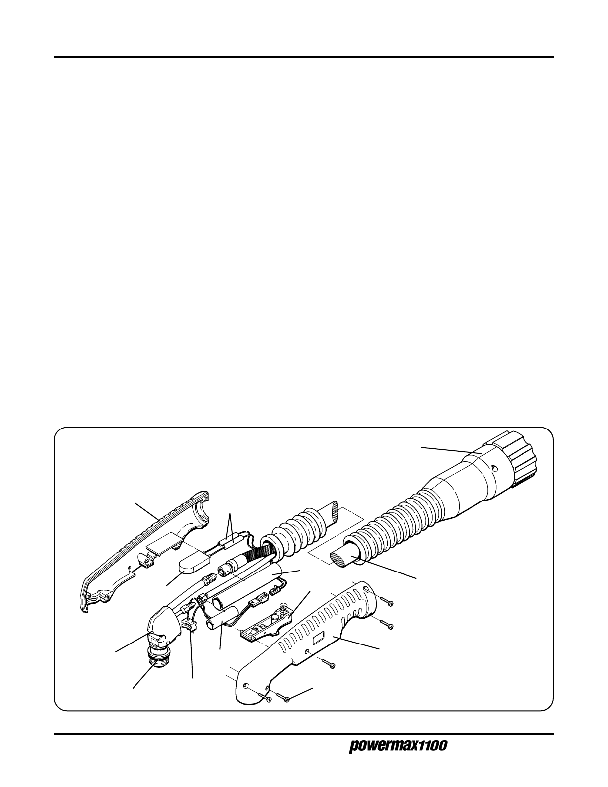
MAINTENANCE/PARTS
PAC135T Torch Assembly and 25 ft (7.6 m) Lead - 085001
PAC135T Torch Assembly and 50 ft (15.2 m) Lead - 085061
Index No. Part No. Description Qty.
002287 Handle Assembly: PAC135T w/screws
1 001615 Handle, PAC135T 1
2 075497 #6 X 5/8 Pillips Head, Pan Head 5
3 002299 Safety Trigger Assembly, PAC135T 1
4 005212 Switch Assembly, Cap on Sensor 1
120473 Electrode, Air: PAC135 1
120474 Swirl Ring: PAC135 1
120475 Shield: PAC135 80A 1
120476 Nozzle: PAC135 80A Shield 1
120483 Retaining Cap: PAC135 1
5 120477 Torch Main Body, PAC135T 1
6 026020 O-Ring: Silicon .864 X .070 1
7 129559* Torch Lead, 25 ft (7.6 m) 1
7 129560** Torch Lead, 50 ft (15.2 m) 1
8 005247 Push Button Switch: Lo-Profile 1
9 128122 Plug Assembly: PAC135T Torch Quick Disconnect 1
10 074069 Splice:22-18 Butt 2
11 046056 Tubing:5/8" ID 4"
12 046072 Heatshrink:1/2" ID 2.5"
* Used only in 085001 ** Used only in 085061
Note: See page 5-8 for detail of consumable parts
1
8
5
4
6
10
11
3
12
2
9
7
1
5-10
7-99
Figure 5-4 PAC135T Torch Assembly and Leads
Operator Manual

MAINTENANCE/PARTS
PAC135M Torch Assembly and 14 ft (4.3 m) Lead - 085062
PAC135M Torch Assembly and 25 ft (7.6 m) Lead - 085063
PAC135M Torch Assembly and 35 ft (10.6 m) Lead - 085064
PAC135M Torch Assembly and 50 ft (15.2 m) Lead - 085065
Index No. Part No. Description Qty.
1 020243................ Sleeve, Torch Position 1
2 129240* .............. Torch Lead, 14 ft (4.3 m) 1
2 129241** ............. Torch Lead, 25 ft (7.6 m) 1
2 129242*** ........... Torch Lead, 35 ft (10.6 m) 1
2 129243**** .......... Torch Lead, 50 ft (15.2 m) 1
3 128122...................... Plug Assembly:PAC135 Torch Quick Disconnect 1
4 008268...................... Plug:3-Socket Female 1
5 108034...................... Receptacle Housing:2-Position 26-22AWG 1
120473................ Electrode 1
120474................ Ring, Swirl 1
120516................ Shield: PAC135M Machine Torch 1
120476................ Nozzle: PAC135 80A Shield 1
120483................ Cap, Retaining 1
6 120508................ Torch Main Body, PAC135M 1
7 026020...................... O-Ring: Silicon .864 X .070 1
8 108035...................... Pin Housing:2-Position 26-22AWG 1
9 108040...................... Contact:PAC135M Cap-On Sensor Switch 1
10 046056...................... Tubing:5/8" ID 4"
11 046072...................... Heatshrink:1/2" ID 2.5"
* Used only in 085062 assembly *** Used only in 085064 assembly
** Used only in 085063 assembly **** Used only in 085065 assembly
Note: See page 5-8 for detail of consumable parts
234
9
10
6
7
11
8
5
2
1
Figure 5-5 PAC135M Torch Assembly and Leads
Operator Manual
5-11

M
AINTENANCE/PARTS
Powermax1100 Field Upgrade Kits and Optional Parts
Part Number Description
028714 ...................................On/Off Pendant with Lead, 25 ft (7.6 m) (Also comes standard with most
machine torch system configurations.)
128061 ...................................On/Off Pendant with Lead, 50 ft (15.2 m)
128062 ...................................On/Off Pendant with Lead, 75 ft (23 m)
128142 ...................................Kit: Wheels, Powermax1100
128143 ...................................Kit: Pilot Arc Controller, Powermax1100
128144 ...................................Kit: Machine Interface, Powermax1100, 208/240/480V
128168 ...................................Kit: Machine Interface, Powermax1100, 200/230/400V
128169 ...................................Kit: Machine Interface, Powermax1100, 230/400V CE
128145 ...................................Kit: Work Cable, 50 ft (15.2 m), Powermax1100
128146 ...................................Kit: Cooling Air Filter, Powermax1100
128147 ...................................Kit: 600V Conversion, Powermax1100
011079 ...................................Filter Element: Gas Supply Filter
129146 ...................................Jumper: Powermax1100 Link Box
023206 ...................................Cable: Machine Interface, 25 ft (7.6 m) (Comes standard with machine torch
system configurations and with machine interface kits.)
109068 ...................................Toroid for power cord ground, Powermax1100 (CE power supplies only)
002282 ...................................Strain Relief Sleeve: 0.875
002283 ...................................Strain Relief Sleeve: 0.750
002286 ...................................Strain Relief Sleeve: 0,625 - Shipped in CE power supply rear panels
Note: Field upgrade kits must be installed by qualified service personnel.
POWER SUPPLIES - 208/240/480V, 1φ/3φ, 50/60 HZ
Part For With Pilot Arc With Machine
Number Torch Type Control Interface
085000 Hand No No
085012 Hand Yes No
085013 Machine No Yes
085014 Machine Yes Yes
POWER SUPPLIES - 200/230/400V, 1φ/3φ, 50/60 HZ
Part For With Pilot Arc With Machine
Number Torch Type Control Interface
085002 Hand No No
085034 Hand Yes No
085035 Machine No Yes
085036 Machine Yes Yes
POWER SUPPLIES - 230/400V CE, 3φ, 50-60 HZ
Part For With Pilot Arc With Machine
Number Torch Type Control Interface
085003 Hand No No
085023 Hand Yes No
085025 Machine No Yes
085024 Machine Yes Yes
Note: Contact your distributor or call the nearest Hypertherm office for hand and machine torch system configurations.
5-12
Operator Manual

A
PPENDIX
A
STANDARDS INDEX
The
Standards Index
practices.
contains a list of publications dealing with plasma arc cutting equipment safety
STANDARDS INDEX
1. ANSI Standard Z49.1,
LeJeune Road, P.O. Box 351020, Miami, FL 33135.
2. NIOSH,
Superintendent of Documents, U.S. Government Printing Office, Washington, D.C. 20402.
3. OSHA,
Washington, D.C. 20402.
4. ANSI Standard Z87.1,
from the American National Standards Institute, 1430 Broadway, New York, NY 10018.
5. ANSI Standard Z41.1,
Standards Institute, 1430 Broadway, New York, NY 10018.
6. ANSI Standard Z49.2,
American National Standards Institute, 1430 Broadway, New York, NY 10018.
7. AWS Standard A6.0,
American Welding Society, 550 LeJeune Road, P.O. Box 351040, Miami, FL 33135.
8. NFPA Standard 51,
Fire Protection Association, 470 Atlantic Avenue, Boston, MA 02210.
9. NFPA Standard 70-1978,
470 Atlantic Avenue, Boston, MA 02210.
Safety and Health in Arc Welding and Gas Welding and Cutting
Safety and Health Standards
Safety in Welding and Cutting
, 29FR 1910, obtainable from the U.S. Government Printing Office,
Safe Practices for Occupation and Educational Eye and Face Protection
Standard for Men's Safety-Toe Footwear
Fire Prevention in the Use of Cutting and Welding Processes
Welding and Cutting Containers Which Have Held Combustibles
Oxygen — Fuel Gas Systems for Welding and Cutting
National Electrical Code
, obtainable from the American Welding Society, 550
, obtainable from the
, obtainable from the American National
, obtainable from the National
, obtainable from the National Fire Protection Association,
, obtainable
, obtainable from the
, obtainable from the
10. NFPA Standard 51B,
Association, 470 Atlantic Avenue, Boston, MA 02210.
11. CGA Pamphlet P-1,
Gas Association, 1235 Jefferson Davis Highway, Arlington, VA 22202.
12. CSA Standard W117.2,
Association Standard Sales, 178 Rexdale Boulevard, Rexdale, Ontario M9W 1R3, Canada.
13. NWSA booklet,
1900 Arch Street, Philadelphia, PA 19103.
14. American Welding Society Standard AWS F4.1,
Welding and Cutting of Containers and Piping That Have Held Hazardous Substances
American Welding Society, 550 LeJeune Road, P.O. Box 351040, Miami, FL 33135.
15. ANSI Standard Z88.2,
Standards Institute, 1430 Broadway, New York, NY 10018.
16. Canadian Electrical Code Part 1,
Standards Association, 178 Rexdale Boulevard, Rexdale, Ontario, Canada M9W1R3.
Cutting and Welding Processes
Safe Handling of Compressed Gases in Cylinders
Code for Safety in Welding and Cutting
Welding Safety Bibliography
Practices for Respiratory Protection
Safety Standards for Electrical Installations
, obtainable from the National Welding Supply Association,
, obtainable from the National Fire Protection
Recommended Safe Practices for the Preparation for
, obtainable from the American National
, obtainable from the Compressed
, obtainable from the Canadian Standards
, obtainable from the Canadian
Operator Manual
, obtainable from the
a-1
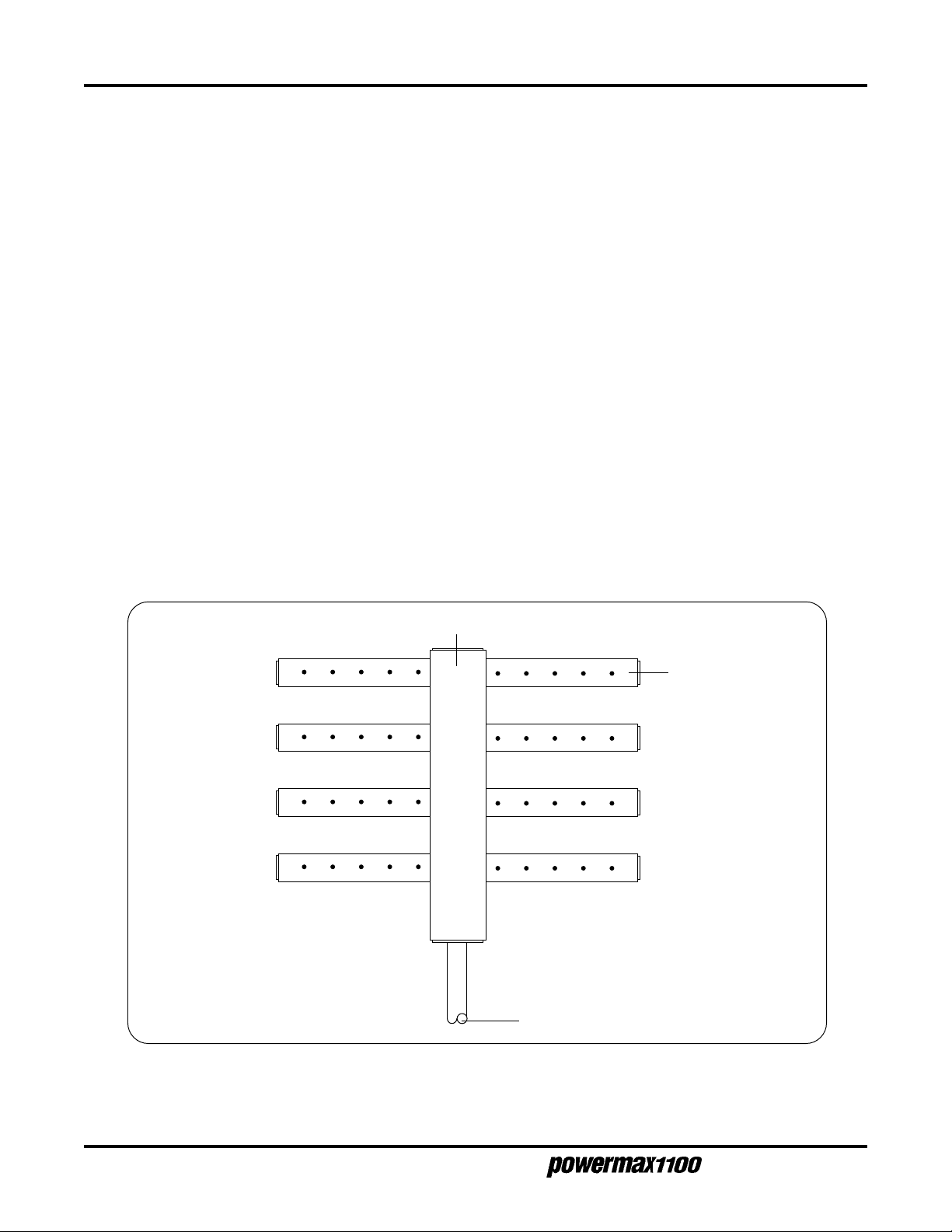
AERATION MANIFOLD
PPENDIX
B
A
AERATION MANIFOLD FOR PLASMA CUTTING ALUMINUM
Introduction
When plasma arc cutting aluminum at the water table surface or below water, free hydrogen gas may
be generated by the cutting process. The high temperature of the plasma process causes
disassociation of oxygen and hydrogen from the water in the water table. The hot aluminum, which has
a high affinity for oxygen, then combines with the oxygen leaving free hydrogen.
An effective means of avoiding free hydrogen buildup is to install an aeration manifold on the floor of
the water table to replenish the oxygen content of the water.
Making an Aeration Manifold - Figure b-1
Make an Aeration Manifold with two-inch (50 mm) PVC tubing with one-inch (25 mm) Distribution
Lines connected to it. Drill 1/8 inch (3 mm) holes every six inches (150 mm) in the distribution lines.
Cap the ends of the distribution lines and install the lines so that oxygen is delivered to all parts of the
cutting area.
Connect the manifold to a shop air line. Set a pressure regulator to obtain a steady stream of bubbles.
Aeration Manifold
Distribution Lines
b-1
Regulated air in
Figure b-1 Aeration Manifold
Operator Manual
 Loading...