


®
Powermax45 XP
Plasma Arc Cutting System
Service Manual
809230 | Revision 2 | English

Powermax, Duramax, FastConnect, Smart Sense, HyAccess, FlushCut, CopperPlus, and Hypertherm are trademarks of
Hypertherm Inc. and may be registered in the United States and other countries. All other trademarks are the property of their
respective holders.
Environmental stewardship is one of Hypertherm’s core values, and it is critical to our success and our customers’ success. We
are striving to reduce the environmental impact of everything we do. For more information:www.hypertherm.com/environment.
© 2018 Hypertherm Inc.

Powermax45 XP
Service Manual
809230
Revision 2
English
Original instructions
April 2018
Hypertherm Inc.
Hanover, NH 03755 USA
www.hypertherm.com

Hypertherm Inc.
Etna Road, P.O. Box 5010
Hanover, NH 03755 USA
603-643-3441 Tel (Main Office)
603-643-5352 Fax (All Departments)
info@hypertherm.com (Main Office Email)
800-643-9878 Tel (Technical Service)
technical.service@hypertherm.com (Technical Service Email)
800-737-2978 Tel (Customer Service)
customer.service@hypertherm.com (Customer Service Email)
866-643-7711 Tel (Return Materials Authorization)
877-371-2876 Fax (Return Materials Authorization)
return.materials@hypertherm.com (RMA email)
Hypertherm México, S.A. de C.V.
Avenida Toluca No. 444, Anexo 1,
Colonia Olivar de los Padres
Delegación Álvaro Obregón
México, D.F. C.P. 01780
52 55 5681 8109 Tel
52 55 5683 2127 Fax
Soporte.Tecnico@hypertherm.com (Technical Service Email)
Hypertherm Plasmatechnik GmbH
Sophie-Scholl-Platz 5
63452 Hanau
Germany
00 800 33 24 97 37 Tel
00 800 49 73 73 29 Fax
31 (0) 165 596900 Tel (Technical Service)
00 800 4973 7843 Tel (Technical Service)
technicalservice.emea@hypertherm.com (Technical Service Email)
Hypertherm (Singapore) Pte Ltd.
82 Genting Lane
Media Centre
Annexe Block #A01-01
Singapore 349567, Republic of Singapore
65 6841 2489 Tel
65 6841 2490 Fax
Marketing.asia@hypertherm.com (Marketing Email)
TechSupportAPAC@hypertherm.com (Technical Service Email)
Hypertherm Japan Ltd.
Level 9, Edobori Center Building
2-1-1 Edobori, Nishi-ku
Osaka 550-0002 Japan
81 6 6225 1183 Tel
81 6 6225 1184 Fax
HTJapan.info@hypertherm.com (Main Office Email)
TechSupportAPAC@hypertherm.com (Technical Service Email)
Hypertherm Europe B.V.
Vaartveld 9, 4704 SE
Roosendaal, Nederland
31 165 596907 Tel
31 165 596901 Fax
31 165 596908 Tel (Marketing)
31 (0) 165 596900 Tel (Technical Service)
00 800 4973 7843 Tel (Technical Service)
technicalservice.emea@hypertherm.com
(Technical Service Email)
Hypertherm (Shanghai) Trading Co., Ltd.
B301, 495 ShangZhong Road
Shanghai, 200231
PR China
86-21-80231122 Tel
86-21-80231120 Fax
86-21-80231128 Tel (Technical Service)
techsupport.china@hypertherm.com
(Technical Service Email)
South America & Central America: Hypertherm Brasil Ltda.
Rua Bras Cubas, 231 – Jardim Maia
Guarulhos, SP – Brasil
CEP 07115-030
55 11 2409 2636 Tel
tecnico.sa@hypertherm.com (Technical Service Email)
Hypertherm Korea Branch
#3904. APEC-ro 17. Heaundae-gu. Busan.
Korea 48060
82 (0)51 747 0358 Tel
82 (0)51 701 0358 Fax
Marketing.korea@hypertherm.com (Marketing Email)
TechSupportAPAC@hypertherm.com
(Technical Service Email)
Hypertherm Pty Limited
GPO Box 4836
Sydney NSW 2001, Australia
61 (0) 437 606 995 Tel
61 7 3219 9010 Fax
au.sales@Hypertherm.com (Main Office Email)
TechSupportAPAC@hypertherm.com
(Technical Service Email)
Hypertherm (India) Thermal Cutting Pvt. Ltd
A-18 / B-1 Extension,
Mohan Co-Operative Industrial Estate,
Mathura Road, New Delhi 110044, India
91-11-40521201/ 2/ 3 Tel
91-11 40521204 Fax
HTIndia.info@hypertherm.com (Main Office Email)
TechSupportAPAC@hypertherm.com
(Technical Service Email)
1/28/16
For training and education resources, go to the Hypertherm Cutting Institute (HCI) online at
www.hypertherm.com/hci.

ENGLISH
WARNING! Before operating any Hypertherm equipment, read the safety
instructions in your product’s manual and in the Safety and Compliance Manual
(80669C). Failure to follow safety instructions can result in personal injury or in
damage to equipment.
Copies of the manuals may accompany the product in electronic and printed
formats. You can also obtain copies of the manuals, in all languages available
for each manual, from the “Documents library” at www.hypertherm.com.
DANSK / DANIS H
ADVARSEL! Inden Hypertherm udstyr tages i brug skal
sikkerhedsinstruktionerne i produktets manual og i Manual om sikkerhed og
overholdelse af krav (80669C), gennemlæses. Følges sikkerhedsvejledningen
ikke kan det resultere i personskade eller beskadigelse af udstyret.
Kopier af manualerne kan ledsage produktet i elektroniske og trykte formater.
Du kan også få kopier af manualer, på alle sprog der er til rådighed for hver
manuel, fra “Dokumentbiblioteket” på www.hypertherm.com.
DEUTSCH / GERMAN
WARNUNG! Bevor Sie ein Hypertherm-Gerät in Betrieb nehmen, lesen
Sie bitte die Sicherheitsanweisungen in Ihrer Bedienungsanleitung sowie im
Handbuch für Sicherheit und Übereinstimmung (80669C). Das Nichtbefolgen
der Sicherheitsanweisungen kann zu Verletzungen von Personen oder
Schäden am Gerät führen.
Bedienungsanleitungen und Handbücher können dem Gerät in
elektronischer Form oder als Druckversion beiliegen. Alle Handbücher
und Anleitungen können in den jeweils verfügbaren Sprachen auch in der
„Dokumente-Bibliothek“ unter www.hypertherm.com heruntergeladen werden.
FRANÇAIS / FRENCH
AVERTISSEMENT! Avant d’utiliser tout équipement Hypertherm, lire les
consignes de sécurité importantes dans le manuel de votre produit et dans
le Manuel de sécurité et de conformité (80669C). Le non-respect des
consignes de sécurité peut engendrer des blessures physiques ou des
dommages à l’équipement.
Des copies de ces manuels peuvent accompagner le produit en format
électronique et papier. Vous pouvez également obtenir des copies de chaque
manuel dans toutes les langues disponibles à partir de la «Bibliothèque
de documents» sur www.hypertherm.com.
ESPAÑOL / SPANISH
¡ADVERTENCIA! Antes de operar cualquier equipo Hypertherm, leer las
instrucciones de seguridad del manual de su producto y del Manual de
Seguridad y Cumplimiento (80669C). No cumplir las instrucciones
de seguridad podría dar lugar a lesiones personales o daño a los equipos.
Pueden venir copias de los manuales en formato electrónico e impreso
junto con el producto. También se pueden obtener copias de los manuales,
en todos los idiomas disponibles para cada manual, de la “Biblioteca
de documentos” en www.hypertherm.com.
ITALIANO / ITALIAN
AVVERTENZA! Prima di usare un’attrezzatura Hypertherm, leggere le istruzioni
sulla sicurezza nel manuale del prodotto e nel Manuale sulla sicurezza e
la conformità (80669C). Il mancato rispetto delle istruzioni sulla sicurezza può
causare lesioni personali o danni all’attrezzatura.
Il prodotto può essere accompagnato da copie elettroniche e cartacee
del manuale. È anche possibile ottenere copie del manuale, in tutte le lingue
disponibili per ogni manuale, dall’“Archivio documenti” all’indirizzo
www.hypertherm.com.
NEDERLANDS / DUTCH
WAARSCHUWING! Lees voordat u Hypertherm-apparatuur gebruikt
de veiligheidsinstructies in de producthandleiding en in de Veiligheids- en
nalevingshandleiding (80669C). Het niet volgen van de veiligheidsinstructies
kan resulteren in persoonlijk letsel of schade aan apparatuur.
De handleidingen kunnen in elektronische en gedrukte vorm met het
product worden meegeleverd. De handleidingen, elke handleiding
beschikbaar in alle talen, zijn ook verkrijgbaar via de “Documentenbibliotheek”
op www.hypertherm.com.
PORTUGUÊS / PORTUGUESE
ADVERTÊNCIA! Antes de operar qualquer equipamento Hypertherm, leia as
instruções de segurança no manual do seu produto e no Manual de Segurança
e de Conformidade (80669C). Não seguir as instruções de segurança pode
resultar em lesões corporais ou danos ao equipamento.
Cópias dos manuais podem acompanhar os produtos nos formatos eletrônico
e impresso. Também é possível obter cópias dos manuais em todos os idiomas
disponíveis para cada manual na “Biblioteca de documentos” em
www.hypertherm.com
日本語 / JAPANESE
警告 ! Hypertherm 機器を操作する前に、安全に関する重要な情報につい
て、この製品説明書にある安全情報、および製品に同梱されている別冊の
「安全とコンプライアンスマニュアル」 (80669C) をお読みください。安全
情報に従わないと怪我や装置の損傷を招くことがあります。
説明書のコピーは、電子フォーマット、または印刷物として製品に同梱さ
れています。各説明書は、 www.hypertherm.com の「ドキュメントライブラ
リ」から各言語で入手できます。
简体中文 / CHINESE (SIMPLIFIED)
警告! 在操作任何海宝设备之前,请阅读产品手册和 《安全和法规遵守手
册》 (80669C) 中的安全操作说明。若未能遵循安全操作说明,可能会造成
人员受伤或设备损坏。
随产品提供的手册可能提供电子版和印刷版两种格式。您也可从
“Documents library” (文档资料库)中获取每本手册所有可用语言的副本,
网址为 www.hypertherm.com.
NORSK / NORWEGIAN
ADVARSEL! Før du bruker noe Hypertherm-utstyr, må du lese
sikkerhetsinstruksjonene i produktets håndbok og i Håndboken om sikkerhet
og samsvar (80669C). Unnlatelse av å følge sikkerhetsinstruksjoner kan føre
til personskade eller skade på utstyr.
Eksemplarer av håndbøkene kan medfølge produktet i elektroniske og trykte
utgaver. Du kan også få eksemplarer av håndbøkene i alle tilgjengelige språk
for hver håndbok fra dokumentbiblioteket på www.hypertherm.com.
SVENSKA / SWEDISH
VARNING! Läs häftet säkerhetsinformationen i din produkts säkerhets- och
efterlevnadsmanual (80669C) för viktig säkerhetsinformation innan du
använder eller underhåller Hypertherm-utrustning. Underlåtenhet att följa
dessa säkerhetsinstruktionerkan resultera i personskador eller skador
på utrustningen.
Kopior av manualen kan medfölja produkten i elektronisk och tryckform.
Du hittar även kopior av manualerna i alla tillgängliga språk
i dokumentbiblioteket (Documents library) på www.hypertherm.com.
한국어 / KOREAN
경고! Hypertherm 장비를 사용하기 전에 제품 설명서와 안전 및 규정
준수 설명서 (80669C)에 나와 있는 안전 지침을 읽으십시오. 안전 지침을
준수하지 않으면 신체 부상이나 장비 손상을 초래할 수 있습니다.
전자 형식과 인쇄된 형식으로 설명서 사본이 제품과 함께 제공될
수 있습니다. www.hypertherm.com 의 'Documents library (문서라이브러리)'
에서도모든언어로이용할수있는설명서사본을얻을수있습니다.
.

ČESKY / CZECH
VAROVÁNÍ! Před uvedením jakéhokoliv zařízení Hypertherm do provozu
si přečtěte bezpečnostní pokyny v příručce k produktu a v Manuálu pro
bezpečnost a dodržování předpisů (80669C). Nedodržování bezpečnostních
pokynů může mít za následek zranění osob nebo poškození majetku.
Kopie příruček a manuálů mohou být součástí dodávky produktu, a to
v elektronické i tištěné formě. Kopie příruček a manuálů ve všech jazykových
verzích, v nichž byly dané příručky a manuály vytvořeny, naleznete v „Knihovně
dokumentů“ na webových stránkách www.hypertherm.com.
TÜRKÇE / TURKISH
UYARI! Bir Hypertherm ekipmanını çalıştırmadan önce, ürün kullanım
kılavuzunda ve Güvenlik ve Uyumluluk Kılavuzu’nda (80669C) yer alan
güvenlik talimatlarını okuyun. Güvenlik talimatlarına uyulmaması durumunda
kişisel yaralanmalar veya ekipman hasarı meydana gelebilir.
Kılavuzların kopyaları, elektronik ve basılı formatta ürünle birlikte verilebilir.
Her biri tüm dillerde yayınlanan kılavuzların kopyalarını www.hypertherm.com
adresindeki “Documents library” (Dosyalar kitaplığı) başlığından da elde
edebilirsiniz.
POLSKI / POLISH
OSTRZEŻENIE! Przed rozpoczęciem obsługi jakiegokolwiek systemu firmy
Hypertherm należy się zapoznać z instrukcjami bezpieczeństwa
zamieszczonymi w podręczniku produktu oraz w Podręczniku bezpieczeństwa
i zgodności (80669C). Nieprzestrzeganie instrukcji bezpieczeństwa może
skutkować obrażeniami ciała i uszkodzeniem sprzętu.
Do produktu mogą być dołączone kopie podręczników w formacie
elektronicznym i drukowanym. Kopie podręczników, wkażdym udostępnionym
języku, można również znaleźć w„Bibliotece dokumentów” pod adresem
www.hypertherm.com.
PУССКИЙ / RUSSIAN
БЕРЕГИСЬ! Перед работой с любым оборудованием Hypertherm
ознакомьтесь с инструкциями по безопасности, представленными
в руководстве, которое поставляется вместе с продуктом, а также
в Руководстве по безопасности и соответствию (80669J). Невыполнение
инструкций по безопасности может привести к телесным повреждениям
или повреждению оборудования.
Копии руководств, которые поставляются вместе с продуктом, могут быть
представлены в электронном и бумажном виде. Копии руководств на всех
языках, на которые переведено то или иное руководство, можно также
загрузить в разделе «Библиотека документов» на веб-сайте
www.hypertherm.com.
SUOMI / FINNISH
VAROITUS! Ennen minkään Hypertherm-laitteen käyttöä lue tuotteen
käyttöoppaassa olevat turvallisuusohjeet ja turvallisuus- ja
vaatimustenmukaisuusohje (80669C). Turvallisuusohjeiden laiminlyönti
voi aiheuttaa henkilökohtaisen loukkaantumisen tai laitevahingon.
Käyttöoppaiden kopiot voivat olla tuotteen mukana elektronisessa ja
tulostetussa muodossa. Voit saada käyttöoppaiden kopiot kaikilla kielillä
”latauskirjastosta”, joka on osoitteessa www.hypertherm.com.
БЪЛГAPCКИ / BULGARIAN
ПРЕДУПРЕЖДЕНИЕ! Преди да работите с което и да е оборудване
Hypertherm, прочетете инструкциите за безопасност в ръководството на
вашия продукт и „Инструкция за безопасност и съответствие“ (80669C).
Неспазването на инструкциите за безопасност би могло да доведе
до телесно нараняване или до повреда на оборудването.
Копия на ръководствата може да придружават продукта в електронен и в
печатен формат. Можете да получите копия на ръководствата, предлагани
на всички езици, от „Documents library“ (Библиотека за документи)
на адрес www.hypertherm.com.
ROMÂNĂ / ROMANIAN
AVERTIZARE! Înainte de utilizarea oricărui echipament Hypertherm, citii
instruciunile de sigurană din cadrul manualului produsului și din cadrul
Manualului de siguranță și conformitate (80669C). Nerespectarea
instruciunilor de sigurană pot rezulta în vătămare personală sau în avarierea
echipamentului.
Produsul poate fi însoit de copii ale manualului în format tipărit și electronic.
De asemenea, dumneavoastră puteţi obţine copii ale manualelor, în toate limbile
disponibile pentru fiecare manual, din cadrul secţiunii „Bibliotecă documente”
aflată pe site-ul www.hypertherm.com.
MAGYAR / HUNGARIAN
VIGYÁZAT! Mielőtt bármilyen Hypertherm berendezést üzemeltetne, olvassa
el a biztonsági információkat a termék kézikönyvében és a Biztonsági és
szabálykövetési kézikönyvben (80669C). A biztonági utasítások betartásának
elmulasztása személyi sérüléshez vagy a berendezés károsodásához vezethet.
A termékhez a kézikönyv példányai elektronikus és nyomtatott formában
is mellékelve lehetnek. A kézikönyvek példányai (minden nyelven) a
www.hypertherm.com
könyvtár) részben is beszerezhetők.
ΕΛΛΗΝΙΚΆ / GREEK
ΠΡΟΕΙΟΠΟΙΗΣΗ! Πριν θέσετε σε λειτουργία οποιονδήποτε εξοπλισό της
Hypertherm, διαβάστε τις οδηγίες ασφαλείας στο εγχειρίδιο του προϊόντος
και στο Εγχειρίδιο ασφάλειας και συμμόρφωσης (80669C). Η η τήρηση
των οδηγιών ασφαλείας πορεί να επιφέρει σωατική βλάβη ή ζηιά στον
εξοπλισό.
Αντίγραφα των εγχειριδίων πορεί να συνοδεύουν το προϊόν σε ηλεκτρονική
και έντυπη ορφή. Μπορείτε, επίσης, να λάβετε αντίγραφα των εγχειριδίων σε
όλες τις γλώσσες που διατίθενται για κάθε εγχειρίδιο από την ψηφιακή
βιβλιοθήκη εγγράφων (Documents library) στη διαδικτυακή τοποθεσία
www.hypertherm.com
繁體中文 / CHINESE (TRADITIONAL)
警告! 在操作任何 Hypertherm 設備前,請閱讀您產品手冊和 《安全和法務
遵從手冊》(80669C) 內的安全指示。不遵守安全指示可能會導致人身傷害
或設備損壞。
手冊複本可能以電子和印刷格式隨附產品提供。您也可以在
www.hypertherm.com 的 「文檔資料庫」內獲取所有手冊的多語種複本。
SLOVENŠČINA / SLOVENIAN
OPOZORILO! Pred uporabo katerekoli Hyperthermove opreme preberite
varnostna navodila v priročniku vašega izdelka ter v Priročniku za varnost
in skladnost (80669C). Neupoštevanje navodil za uporabo lahko povzroči
telesne poškodbe ali materialno škodo.
Izdelku so lahko priloženi izvodi priročnikov v elektronski ali tiskani obliki. Izvode
priročnikov v vseh razpoložljivih jezikih si lahko prenesete tudi iz knjižnice
dokumentov “Documents library” na naslovu www.hypertherm.com.
SRPSKI / SERBIAN
UPOZORENJE! Pre rukovanja bilo kojom Hyperthermovom opremom
pročitajte uputstva o bezbednosti u svom priručniku za proizvod i u Priručniku
o bezbednosti i usaglašenosti (80669C). Oglušavanje o praćenje uputstava
o bezbednosti može da ima za posledicu ličnu povredu ili oštećenje opreme.
Može se dogoditi da kopije priručnika prate proizvod u elektronskom
i štampanom formatu. Takođe možete da pronađete kopije priručnika, na svim
jezicima koji su dostupni za svaki od priručnika, u “Biblioteci dokumenata”
(“Documents library”) na www.hypertherm.com.
SLOVENČINA / SLOVAK
VÝSTRAHA! Pred použitím akéhokoľvek zariadenia od spoločnosti Hypertherm
si prečítajte bezpečnostné pokyny v návode na obsluhu vášho zariadenia
avManuáli o bezpečnosti a súlade s normami (80669C). V prípade
nedodržania bezpečnostných pokynov môže dôjsť k ujme na zdraví alebo
poškodeniu zariadenia.
Kópia návodu, ktorá je dodávaná s produktom, môže mať elektronickú
alebo tlačenú podobu. Kópie návodov, vo všetkých dostupných jazykoch,
sú k dispozícii aj v sekcii z „knižnice Dokumenty“ na www.hypertherm.com.
weboldalon a „Documents library” (Dokumentum
.

Contents
Electromagnetic Compatibility (EMC) ............................................................................ SC-17
Introduction....................................................................................................................................................SC-17
Installation and use ......................................................................................................................................SC-17
Assessment of area .....................................................................................................................................SC-17
Methods of reducing emissions................................................................................................................SC-17
Mains supply......................................................................................................................................SC-17
Maintenance of cutting equipment...........................................................................................................SC-17
Cutting cables...............................................................................................................................................SC-17
Equipotential bonding .....................................................................................................................SC-17
Earthing of the workpiece ..............................................................................................................SC-18
Screening and shielding.............................................................................................................................SC-18
Warranty............................................................................................................................... SC-19
Attention.........................................................................................................................................................SC-19
General...........................................................................................................................................................SC-19
Patent indemnity...........................................................................................................................................SC-19
Limitation of liability......................................................................................................................................SC-19
National and local codes............................................................................................................................SC-19
Liability cap....................................................................................................................................................SC-20
Insurance........................................................................................................................................................SC-20
Transfer of rights ..........................................................................................................................................SC-20
Powermax45 XP Service Manual 809230 7

Contents
Waterjet product warranty coverage.......................................................................................................SC-20
Product...............................................................................................................................................SC-20
Parts coverage..................................................................................................................................SC-20
1 Installation and Setup.............................................................................................................. 21
System contents.................................................................................................................................................. 22
What to do if components are missing or damaged....................................................................... 23
Hypertherm plasma power supply ratings..................................................................................................... 23
Cutting specifications ........................................................................................................................................ 24
Recommended cut capacity – handheld........................................................................................... 24
Pierce capacity ........................................................................................................................................ 24
Maximum cut speeds (mild steel)........................................................................................................ 25
Gouge capacity ....................................................................................................................................... 25
Noise levels............................................................................................................................................... 25
Position the plasma power supply .................................................................................................................. 26
Power supply dimensions and weight................................................................................................ 28
Work lead weights...................................................................................................................... 28
Connect to electrical power ............................................................................................................................. 29
Install a line-disconnect switch............................................................................................................ 29
Requirements for grounding................................................................................................................. 30
The system’s rated output (cutting power) ....................................................................................... 30
Voltage configurations ........................................................................................................................... 30
CSA/CE/CCC 200 V – 240 V (1-phase) ............................................................................ 31
CSA 208 V (1-phase)................................................................................................................ 31
CCC 220 V (1-phase)............................................................................................................... 31
CE 230 V (1-phase)................................................................................................................... 31
CCC 380 V (3-phase)............................................................................................................... 32
CE 400 V (3-phase)................................................................................................................... 32
CSA 480 V (3-phase)................................................................................................................ 32
Decrease output current and arc stretch for lower rated electrical service .............................. 33
Example: 230 V input on 20 A electrical service................................................................. 33
Prepare the power cord..................................................................................................................................... 34
CSA systems ........................................................................................................................................... 34
1-phase (200 V – 240 V).......................................................................................................... 34
3-phase (480 V).......................................................................................................................... 34
CE/CCC systems................................................................................................................................... 34
1-phase (200 V – 240 V).......................................................................................................... 34
3-phase (380 V / 400 V)........................................................................................................... 34
Extension cord recommendations....................................................................................................... 35
8 809230 Service Manual Powermax45 XP

Contents
Generator recommendations................................................................................................................ 35
Adapter for 4-wire 1-phase connections (CSA 1-phase models only) ......................... 36
Connect the gas supply .................................................................................................................................... 36
Gas supply source.................................................................................................................................. 37
High-pressure gas cylinders..................................................................................................... 38
Gas flow rates.......................................................................................................................................... 39
Minimum inlet pressure (while gas is flowing).................................................................................. 39
Cutting........................................................................................................................................... 39
Maximum control gouging (26 – 45 A).................................................................................. 40
Precision gouging / Marking (10 – 25 A).............................................................................. 40
Additional gas filtration........................................................................................................................... 41
2 Operation.................................................................................................................................... 43
Controls and indicators ..................................................................................................................................... 43
ON (I)/OFF(O) power switch ........................................................................................................... 43
Cutting controls....................................................................................................................................... 44
Indicator LEDs ......................................................................................................................................... 45
Disable the torch................................................................................................................................................. 46
Warning puffs of air................................................................................................................................ 47
For hand torches ......................................................................................................................... 48
For machine torches................................................................................................................... 48
Operate the plasma system.............................................................................................................................. 48
Step 1 – Install consumables and activate torch ............................................................................ 48
Step 2 – Connect torch lead ............................................................................................................... 50
Step 3 – Connect gas supply.............................................................................................................. 51
Step 4 – Connect work lead and work clamp ................................................................................. 51
Work lead...................................................................................................................................... 51
Work clamp .................................................................................................................................. 52
Step 5 – Connect electric power and turn ON the system.......................................................... 53
Step 6 – Set mode and adjust output current (amperage)........................................................... 53
Cutting expanded metal............................................................................................................. 54
Step 7 – Check cut settings and indicator LEDs............................................................................ 54
What to expect during and after cutting........................................................................................................ 55
Adjust the gas pressure manually ................................................................................................................... 56
Reset the gas pressure.......................................................................................................................... 58
Change the gas pressure values between psi and bar.............................................................................. 59
Understand duty cycle to prevent overheating............................................................................................. 60
Powermax45 XP Service Manual 809230 9

Contents
3 Cut with the Hand Torch.......................................................................................................... 61
Hand torch components, dimensions, weights............................................................................................ 62
Components............................................................................................................................................. 62
Dimensions ............................................................................................................................................... 62
75° hand torch ............................................................................................................................. 62
15° hand torch ............................................................................................................................. 62
Weights..................................................................................................................................................... 63
Minimum bend radius for torch leads ................................................................................................. 63
Choose the consumables ................................................................................................................................. 64
Shielded drag-cutting consumables................................................................................................... 65
FineCut consumables ............................................................................................................................ 65
Specialty consumables.......................................................................................................................... 65
HyAccess cutting consumables .............................................................................................. 65
FlushCut™ consumables ........................................................................................................... 66
CopperPlus™ electrode............................................................................................................. 68
Consumable life................................................................................................................................................... 68
Prepare to fire the torch..................................................................................................................................... 70
Hand torch cutting guidelines.......................................................................................................................... 72
Start a cut from the edge of the workpiece .................................................................................................. 73
Pierce a workpiece ............................................................................................................................................. 74
4 Gouge with the Hand Torch and Machine Torch ................................................................ 77
Gouging processes............................................................................................................................................ 77
Maximum Control gouging.................................................................................................................... 78
Maximum Control gouging consumables (26 – 45 A)....................................................... 78
Precision gouging ................................................................................................................................... 78
Precision gouging consumables (10 – 25 A) ...................................................................... 78
Specialty consumables.......................................................................................................................... 79
HyAccess gouging consumables............................................................................................ 79
How to control the gouge profile .................................................................................................................... 80
Gouge with the hand torch............................................................................................................................... 81
Remove spot welds ................................................................................................................................ 82
Tips................................................................................................................................................. 82
Procedure ..................................................................................................................................... 83
Gouge with the machine torch ........................................................................................................................ 86
Typical gouge profiles............................................................................................................................ 87
Maximum Control gouging consumables (45 A) ................................................................. 87
Precision gouging consumables (10 A)................................................................................. 89
Troubleshooting tips for gouging .................................................................................................................... 91
10 809230 Service Manual Powermax45 XP

Contents
5 Set Up the Machine Torch ...................................................................................................... 93
Machine torch components, dimensions, weights ...................................................................................... 94
Components............................................................................................................................................. 94
Dimensions ............................................................................................................................................... 94
Weights..................................................................................................................................................... 95
Minimum bend radius for torch leads ................................................................................................. 95
Mount the torch ................................................................................................................................................... 95
Remove the gear rack ............................................................................................................................ 95
Disassemble the machine torch........................................................................................................... 96
Assemble the machine torch................................................................................................................ 98
Align the torch................................................................................................................................................... 100
6 Configure Controls for Mechanized Cutting...................................................................... 101
Machine torch setup overview ...................................................................................................................... 101
Set up the plasma system and machine torch for mechanized cutting................................... 102
Connect the remote-start pendant .............................................................................................................. 103
Connect the machine interface cable ......................................................................................................... 104
External cables that do not use voltage divider board................................................................. 104
External cables that use voltage divider board.............................................................................. 105
Cable signals (for troubleshooting)...................................................................................... 106
External cables for PlasmaCAM
Cable signals (for troubleshooting)...................................................................................... 107
Installation of the machine interface cable ..................................................................................... 108
Machine interface pinout ........................................................................................................ 108
Machine interface cable signals............................................................................................ 109
Set the 5-position voltage divider ........................................................................................ 110
Access raw arc voltage .................................................................................................................................. 111
Connect an optional RS-485 serial interface cable ................................................................................ 111
External serial port cables .................................................................................................................. 112
Remote mode........................................................................................................................................ 112
®
tables ............................................................................. 107
7 Cut with the Machine Torch................................................................................................. 113
Choose the consumables .............................................................................................................................. 113
Mechanized shielded consumables................................................................................................. 114
Mechanized shielded consumables with ohmic retaining cap................................................... 114
FineCut shielded consumables with ohmic retaining cap.......................................................... 115
FineCut unshielded consumables.................................................................................................... 115
Consumable life................................................................................................................................................ 115
Powermax45 XP Service Manual 809230 11

Contents
Understand and optimize cut quality ........................................................................................................... 116
Cut or bevel angle................................................................................................................................ 116
Dross....................................................................................................................................................... 117
Pierce a workpiece using the machine torch............................................................................................. 118
Pierce delay........................................................................................................................................... 118
Pierce height ......................................................................................................................................... 118
Pierce maximum thickness................................................................................................................. 118
Cut stainless steel with F5............................................................................................................................. 119
8 Guidelines for Marking.......................................................................................................... 121
Marking consumables (10 – 25 A) .............................................................................................................. 121
Process gas: air versus argon....................................................................................................................... 122
How the system handles postflow for marking ............................................................................. 122
Types of marking .............................................................................................................................................. 123
Marking samples................................................................................................................................... 123
Marking, scoring, and dimpling profiles .......................................................................................... 125
Marking process guidelines........................................................................................................................... 126
Cornering guidelines ........................................................................................................................... 127
Marking troubleshooting tips......................................................................................................................... 127
Common marking problems and solutions..................................................................................... 128
9 Cut Charts and Marking Charts........................................................................................... 131
Using the cut charts ........................................................................................................................................ 132
Mild Steel – 45 A – Air – Shielded ............................................................................................................. 134
Stainless Steel – 45 A – Air – Shielded .................................................................................................... 135
Aluminum – 45 A – Air – Shielded.............................................................................................................. 136
Mild Steel – FineCut – Air – Shielded and Unshielded.......................................................................... 137
Stainless Steel – FineCut – Air – Shielded and Unshielded................................................................. 138
Mild Steel – FineCut Low Speed – Air – Shielded and Unshielded ................................................... 139
Stainless Steel – FineCut Low Speed – Air – Shielded and Unshielded.......................................... 140
Stainless Steel – 45 A – F5 – Shielded..................................................................................................... 141
Marking and Dimpling – Air – Shielded...................................................................................................... 142
Marking and Dimpling – Argon – Shielded................................................................................................ 143
12 809230 Service Manual Powermax45 XP

Contents
10 Troubleshooting and System Tests ..................................................................................... 145
Theory of operation.......................................................................................................................................... 145
Overview ................................................................................................................................................ 145
200 – 240 V 1-phase power supply functional description...................................................... 145
400 V CE/CCC 3-phase power supply functional description................................................ 146
480 V CSA 3-phase power supply functional description ........................................................ 147
Sequence of operation ....................................................................................................................... 148
Troubleshooting preparation ......................................................................................................................... 149
Troubleshooting procedures and sequence.................................................................................. 150
Test equipment..................................................................................................................................... 151
External inspection............................................................................................................................... 151
Internal inspection................................................................................................................................ 151
Initial resistance check.................................................................................................................................... 152
Check the power switch and snubber resistors ........................................................................... 152
Check the gas pressure ................................................................................................................................. 156
Check the gas quality...................................................................................................................................... 157
Run a gas test................................................................................................................................................... 158
Enter gas test mode ............................................................................................................................ 158
While gas test mode is active ............................................................................................... 159
Exit gas test mode................................................................................................................................ 159
Cold restarts and quick restarts ................................................................................................................... 160
Perform a cold restart.......................................................................................................................... 160
Perform a quick restart........................................................................................................................ 160
Power supply overview ................................................................................................................................... 161
200 – 240 V 1-phase power supply............................................................................................... 161
400 V CE/CCC and 480 V CSA 3-phase power supply.......................................................... 162
Fault LEDs and fault codes............................................................................................................................ 163
Internal component faults (fault code formats 1-nn-n, 2-nn-n, 3-nn-n) ................................. 168
Gas Pressure fault LED ...................................................................................................................... 170
Torch Cap fault LED............................................................................................................................ 171
Generator considerations................................................................................................................... 172
Troubleshooting guide ........................................................................................................................ 172
Issues with cut quality......................................................................................................................... 176
Torch-related faults.............................................................................................................................. 178
Continuity check....................................................................................................................... 178
Torch-disable switch and warning puffs of air .................................................................. 178
Power board LEDs........................................................................................................................................... 179
When the Reset LED indicates a DSP fault .................................................................................. 180
Powermax45 XP Service Manual 809230 13

Contents
System tests...................................................................................................................................................... 181
Grounding options............................................................................................................................... 182
Test 1 – voltage input ......................................................................................................................... 183
Check the incoming voltage .................................................................................................. 183
Check the voltage at the power switch .............................................................................. 185
Test 2 – power board voltage checks ............................................................................................ 187
Test 3 – VBUS and voltage balance on power board ................................................................ 189
Test 4 – solenoid valve – no gas input ........................................................................................... 192
Test valve after cold restart.................................................................................................... 193
Test valve after disconnecting from power board ............................................................ 194
Test 5 – solenoid valve – low gas pressure .................................................................................. 195
External checks......................................................................................................................... 195
Internal checks.......................................................................................................................... 196
Cold restart................................................................................................................................ 196
Test 6 – solenoid valve pressure sensor........................................................................................ 197
Check for electrical interference and pinched wires ....................................................... 197
Check the power input and solenoid valve coils .............................................................. 198
Check the solenoid valve sensor and power board sensor input................................. 200
Test 7 – torch stuck open (TSO) or torch stuck closed (TSC) ................................................ 201
Test 8 – plasma start........................................................................................................................... 204
Test 9 – torch cap sensor.................................................................................................................. 206
Check the torch and the torch lead..................................................................................... 206
Check the power supply (torch receptacle and power board) ..................................... 207
Test 10 – fan......................................................................................................................................... 209
Test 11 – power switch trip coil (1-phase models)..................................................................... 210
11 Power Supply Component Replacement............................................................................. 211
Install a machine interface cable for raw arc voltage............................................................................... 212
Replace the air filter bowl and filter element.............................................................................................. 212
Replace the power supply cover and handle ............................................................................................ 215
Replace the component barrier .................................................................................................................... 218
Detach and reattach the front panel............................................................................................................ 220
Detach and reattach the rear panel ............................................................................................................. 223
Replace the machine interface (CPC) port and voltage divider board ............................................... 227
Set the voltage divider board ............................................................................................................ 230
Install the RS-485 serial interface port....................................................................................................... 231
Replace the display board and ribbon cable............................................................................................. 234
Replace the power switch – 1-phase models .......................................................................................... 236
Replace the power switch – 3-phase models .......................................................................................... 237
Replace the power cord and strain relief – 1-phase models ................................................................ 239
14 809230 Service Manual Powermax45 XP

Contents
Replace the power cord and strain relief – 3-phase models ................................................................ 241
Replace the EMI board (CE/CCC 1-phase models only)...................................................................... 243
Replace internal wires – 1-phase models.................................................................................................. 245
Replace internal wires – 3-phase models.................................................................................................. 249
Replace the power board............................................................................................................................... 253
Replace the snubber resistors...................................................................................................................... 259
Replace the capacitors................................................................................................................................... 261
Replace the fan................................................................................................................................................. 264
Replace the air filter assembly ...................................................................................................................... 267
Replace the gas inlet fittings ......................................................................................................................... 269
Replace the solenoid valve assembly.......................................................................................................... 271
Replace the gas supply hoses and 90° fitting........................................................................................... 274
Replace the front panel................................................................................................................................... 276
Replace the torch quick-disconnect receptacle....................................................................................... 277
Replace the work lead receptacle................................................................................................................ 280
Replace the rear panel.................................................................................................................................... 282
12 Hand Torch Component Replacement................................................................................. 285
Torch components........................................................................................................................................... 286
75° hand torch...................................................................................................................................... 286
15° hand torch...................................................................................................................................... 287
Replace the handle.......................................................................................................................................... 288
Replace the torch-disable slider................................................................................................................... 293
Replace the trigger assembly........................................................................................................................ 294
Replace the torch body or the torch lead................................................................................................... 295
Torch body replacement kits ............................................................................................................. 295
Torch lead replacement kits............................................................................................................... 295
Replace the start switch................................................................................................................................. 298
Replace the cap-sensor switch/torch-disable switch assembly........................................................... 299
Replace the quick-disconnect shell............................................................................................................. 300
13 Machine Torch Component Replacement .......................................................................... 303
Torch components........................................................................................................................................... 304
Replace the torch shell................................................................................................................................... 305
Replace the torch-disable slider................................................................................................................... 310
Replace the torch body or the torch lead................................................................................................... 311
Torch main body replacement kit ..................................................................................................... 311
Torch lead replacement kits............................................................................................................... 311
Powermax45 XP Service Manual 809230 15

Contents
Replace the cap-sensor switch/torch-disable switch assembly........................................................... 314
Replace the quick-disconnect shell............................................................................................................. 315
14 Replacement Parts and Accessories .................................................................................. 317
Plasma supply exterior, front.......................................................................................................................... 318
Plasma supply exterior, rear........................................................................................................................... 319
Machine interface (CPC) and serial interface upgrade kits................................................................... 320
External cables for machine interface port and serial port ......................................................... 321
Front panel and receptacles, display board, power switch.................................................................... 322
Plasma supply interior, power board ........................................................................................................... 323
Plasma supply interior, pneumatics and fan............................................................................................... 324
Plasma supply interior, wires, CSA 1-phase ............................................................................................. 325
Plasma supply interior, wires and EMI board, CE/CCC 1-phase ........................................................ 326
Plasma supply interior, wires, 3-phase ....................................................................................................... 327
75° hand torch replacement parts ............................................................................................................... 328
15° hand torch replacement parts ............................................................................................................... 329
Machine torch replacement parts................................................................................................................. 330
Accessory parts................................................................................................................................................ 332
Safety critical parts .......................................................................................................................................... 333
Recommended spare parts ........................................................................................................................... 334
Powermax45 XP Labels ................................................................................................................................. 336
Consumable labels and fault codes label....................................................................................... 336
CSA warning label............................................................................................................................... 337
CE/CCC warning label....................................................................................................................... 338
Data plate........................................................................................................................................................... 339
Symbols and marks ......................................................................................................................................... 340
IEC symbols .......................................................................................................................................... 341
15 System Diagrams.................................................................................................................... 343
Powermax45 XP schematic – 200 – 240 V 1-phase models .............................................................. 345
Powermax45 XP schematic – 400 V CE/CCC and 480 V CSA 3-phase models ......................... 346
Timing chart for torch start............................................................................................................................. 347
16 809230 Service Manual Powermax45 XP

Electromagnetic Compatibility (EMC)
Introduction
Hypertherm’s CE-marked equipment is built in compliance with standard
EN60974-10. The equipment should be installed and used in
accordance with the information below to achieve electromagnetic
compatibility.
The limits required by EN60974-10 may not be adequate to completely
eliminate interference when the affected equipment is in close proximity
or has a high degree of sensitivity. In such cases it may be necessary to
use other measures to further reduce interference.
This cutting equipment is designed for use only in an industrial
environment.
Installation and use
The user is responsible for installing and using the plasma equipment
according to the manufacturer’s instructions.
If electromagnetic disturbances are detected then it shall be the
responsibility of the user to resolve the situation with the technical
assistance of the manufacturer. In some cases this remedial action may
be as simple as earthing the cutting circuit, see Earthing of the
workpiece. In other cases, it could involve constructing an
electromagnetic screen enclosing the power source and the work
complete with associated input filters. In all cases, electromagnetic
disturbances must be reduced to the point where they are no longer
troublesome.
Methods of reducing emissions
Mains supply
Cutting equipment must be connected to the mains supply according to
the manufacturer’s recommendations. If interference occurs, it may be
necessary to take additional precautions such as filtering of the mains
supply.
Consideration should be given to shielding the supply cable of
permanently installed cutting equipment, in metallic conduit or
equivalent. Shielding should be electrically continuous throughout its
length. The shielding should be connected to the cutting mains supply so
that good electrical contact is maintained between the conduit and the
cutting power source enclosure.
Maintenance of cutting equipment
The cutting equipment must be routinely maintained according to the
manufacturer’s recommendations. All access and service doors and
covers should be closed and properly fastened when the cutting
equipment is in operation. The cutting equipment should not be modified
in any way, except as set forth in and in accordance with the
manufacturer’s written instructions. For example, the spark gaps of arc
striking and stabilizing devices should be adjusted and maintained
according to the manufacturer’s recommendations.
Cutting cables
Assessment of area
Before installing the equipment, the user shall make an assessment of
potential electromagnetic problems in the surrounding area. The
following shall be taken into account:
a. Other supply cables, control cables, signaling and telephone
cables; above, below and adjacent to the cutting equipment.
b. Radio and television transmitters and receivers.
c. Computer and other control equipment.
d. Safety critical equipment, for example guarding of industrial
equipment.
e. Health of the people around, for example the use of
pacemakers and hearing aids.
f. Equipment used for calibration or measurement.
g. Immunity of other equipment in the environment. User shall
ensure that other equipment being used in the environment is
compatible. This may require additional protection measures.
h. Time of day that cutting or other activities are to be carried
out.
The size of the surrounding area to be considered will depend on the
structure of the building and other activities that are taking place. The
surrounding area may extend beyond the boundaries of the premises.
The cutting cables should be kept as short as possible and should be
positioned close together, running at or close to the floor level.
Equipotential bonding
Bonding of all metallic components in the cutting installation and
adjacent to it should be considered.
However, metallic components bonded to the workpiece will increase
the risk that the operator could receive a shock by touching these
metallic components and the electrode (nozzle for laser heads) at the
same time.
The operator should be insulated from all such bonded metallic
components.
Safety and compliance SC-17

Electromagnetic Compatibility (EMC)
Earthing of the workpiece
Where the workpiece is not bonded to earth for electrical safety, nor
connected to earth because of its size and position, for example, ship’s
hull or building steel work, a connection bonding the workpiece to earth
may reduce emissions in some, but not all instances. Care should be
taken to prevent the earthing of the workpiece increasing the risk of injury
to users, or damage to other electrical equipment. Where necessary, the
connection of the workpiece to earth should be made by a direct
connection to the workpiece, but in some countries where direct
connection is not permitted, the bonding should be achieved by suitable
capacitances selected according to national regulations.
Note: The cutting circuit may or may not be earthed for safety reasons.
Changing the earthing arrangements should only be authorized by a
person who is competent to assess whether the changes will increase
the risk of injury, for example, by allowing parallel cutting current return
paths which may damage the earth circuits of other equipment.
Further guidance is provided in IEC 60974-9, Arc Welding Equipment,
Part 9: Installation and Use.
Screening and shielding
Selective screening and shielding of other cables and equipment in the
surrounding area may alleviate problems of interference. Screening of the
entire plasma cutting installation may be considered for special
applications.
SC-18 Safety and compliance

Warranty
Attention
Genuine Hypertherm parts are the factory-recommended replacement
parts for your Hypertherm system. Any damage or injury caused by the
use of other than genuine Hypertherm parts may not be covered by the
Hypertherm warranty, and will constitute misuse of the Hypertherm
Product.
You are solely responsible for the safe use of the Product. Hypertherm
does not and cannot make any guarantee or warranty regarding the safe
use of the product in your environment.
General
Hypertherm Inc. warrants that its Products shall be free from defects in
materials and workmanship for the specific periods of time set forth
herein and as follows: if Hypertherm is notified of a defect (i) with respect
to the plasma power supply within a period of two (2) years from the date
of its delivery to you, with the exception of Powermax brand power
supplies, which shall be within a period of three (3) years from the date of
delivery to you, and (ii) with respect to the torch and leads within a period
of one (1) year from its date of delivery to you, with the exception of the
HPRXD short torch with integrated lead, which shall be within a period of
six (6) months from the date of delivery to you, and with respect to torch
lifter assemblies within a period of one (1) year from its date of delivery to
you, and with respect to Automation products one (1) year from its date
of delivery to you, with the exception of the EDGE Connect CNC,
EDGE Connect T CNC, EDGE Connect TC CNC, EDGE Pro CNC,
EDGE Pro Ti CNC, MicroEDGE Pro CNC, and ArcGlide THC, which
shall be within a period of two (2) years from the date of delivery to you,
and (iii) with respect to HyIntensity fiber laser components within a
period of two (2) years from the date of its delivery to you, with the
exception of laser heads and beam delivery cables, which shall be within
a period of one (1) year from its date of delivery to you.
This warranty shall not apply to any Powermax brand power supplies that
have been used with phase converters. In addition, Hypertherm does not
warranty systems that have been damaged as a result of poor power
quality, whether from phase converters or incoming line power. This
warranty shall not apply to any product which has been incorrectly
installed, modified, or otherwise damaged.
Hypertherm provides repair, replacement or adjustment of the Product as
the sole and exclusive remedy, if and only if the warranty set forth herein
properly is invoked and applies. Hypertherm, at its sole option, shall
repair, replace, or adjust, free of charge, any defective Products covered
by this warranty which shall be returned with Hypertherm’s prior
authorization (which shall not be unreasonably withheld), properly
packed, to Hypertherm’s place of business in Hanover, New Hampshire,
or to an authorized Hypertherm repair facility, all costs, insurance and
freight pre paid by the customer. Hypertherm shall not be liable for any
repairs, replacement, or adjustments of Products covered by this
warranty, except those made pursuant to this paragraph and with
Hypertherm’s prior written consent.
The warranty set forth above is exclusive and is in lieu of all other
warranties, express, implied, statutory, or otherwise with respect to the
Products or as to the results which may be obtained therefrom, and all
implied warranties or conditions of quality or of merchantability or fitness
for a particular purpose or against infringement. The foregoing shall
constitute the sole and exclusive remedy for any breach by Hypertherm
of its warranty.
Distributors/OEMs may offer different or additional warranties, but
Distributors/OEMs are not authorized to give any additional warranty
protection to you or make any representation to you purporting to be
binding upon Hypertherm.
Patent indemnity
Except only in cases of products not manufactured by Hypertherm or
manufactured by a person other than Hypertherm not in strict conformity
with Hypertherm’s specifications and in cases of designs, processes,
formulae, or combinations not developed or purported to be developed
by Hypertherm, Hypertherm will have the right to defend or settle, at its
own expense, any suit or proceeding brought against you alleging that
the use of the Hypertherm product, alone and not in combination with
any other product not supplied by Hypertherm, infringes any patent of
any third party. You shall notify Hypertherm promptly upon learning of any
action or threatened action in connection with any such alleged
infringement (and in any event no longer than fourteen (14) days after
learning of any action or threat of action), and Hypertherm’s obligation to
defend shall be conditioned upon Hypertherm’s sole control of, and the
indemnified party’s cooperation and assistance in, the defense of the
claim.
Limitation of liability
In no event shall Hypertherm be liable to any person or entity for
any incidental, consequential direct, indirect, punitive or
exemplary damages (including but not limited to lost profits)
regardless of whether such liability is based on breach of
contract, tort, strict liability, breach of warranty, failure of
essential purpose, or otherwise, and even if advised of the
possibility of such damages. Hypertherm shall not be liable for
any losses to Distributor based on down time, lost production or
lost profits. It is the intention of the Distributor and Hypertherm
that this provision be construed by a court as being the
broadest limitation of liability consistent with applicable law.
National and local codes
National and local codes governing plumbing and electrical installation
shall take precedence over any instructions contained in this manual.
In no event shall Hypertherm be liable for injury to persons or property
damage by reason of any code violation or poor work practices.
Safety and compliance SC-19

Warranty
Liability cap
In no event shall Hypertherm’s liability, if any, whether such
liability is based on breach of contract, tort, strict liability,
breach of warranties, failure of essential purpose or otherwise,
for any claim, action, suit or proceeding (whether in court,
arbitration, regulatory proceeding or otherwise) arising out of or
relating to the use of the Products exceed in the aggregate the
amount paid for the Products that gave rise to such claim.
Insurance
At all times you will have and maintain insurance in such quantities and
types, and with coverage sufficient and appropriate to defend and to hold
Hypertherm harmless in the event of any cause of action arising from the
use of the products.
Transfer of rights
You may transfer any remaining rights you may have hereunder only in
connection with the sale of all or substantially all of your assets or capital
stock to a successor in interest who agrees to be bound by all of the
terms and conditions of this Warranty. Within thirty (30) days before any
such transfer occurs, you agree to notify in writing Hypertherm, which
reserves the right of approval. Should you fail timely to notify Hypertherm
and seek its approval as set forth herein, the Warranty set forth herein
shall be null and void and you will have no further recourse against
Hypertherm under the Warranty or otherwise.
Waterjet product warranty coverage
Product Parts coverage
HyPrecision pumps 27 months from the ship date, or 24 months
from the date of proven installation, or
4,000 hours, whichever occurs first
PowerDredge
abrasive removal
system
EcoSift abrasive
recycling system
Abrasive metering
devices
On/off valve air
actuators
Diamond orifices 600 hours of use with the use of a thimble
Consumable parts are not covered by this warranty. Consumable parts
include, but are not limited to, high-pressure water seals, check valves,
cylinders, bleed-down valves, low-pressure seals, high-pressure tubing,
low- and high-pressure water filters and abrasive collection bags. All
third-party pumps, pump accessories, hoppers, hopper accessories,
dryer boxes, dryer box accessories and plumbing accessories are
covered by the respective manufacturers’ warranties and not covered by
this warranty.
15 months from the ship date or 12 months
from the date of proven installation,
whichever occurs first
15 months from the ship date or 12 months
from the date of proven installation,
whichever occurs first
15 months from the ship date or 12 months
from the date of proven installation,
whichever occurs first
15 months from the ship date or 12 months
from the date of proven installation,
whichever occurs first
filter and compliance with Hypertherm’s
water quality requirements
SC-20 Safety and compliance

Installation and Setup
The Powermax45 XP is a portable 45 A plasma cutting system that you can use for many handheld
and mechanized cutting and gouging applications. The system’s automatic gas and
automatic voltage features make it easy to set up and use even if you have limited plasma cutting
experience.
With the Powermax45 XP you can:
Use air or nitrogen to cut electrically
conductive metals such as mild steel,
stainless steel, and aluminum
Cut thicknesses up to 16 mm (5/8 inch)
Pierce thicknesses up to 12 mm (1/2 inch)
Sever thicknesses up to 29 mm (1-1/8 inch)
Use 2 different gouging processes for a wide
range of gouging applications: Maximum
Control gouging (26 A – 45 A) and Precision
gouging (10 A – 25 A)
Mark metal surfaces using air or argon
Use F5 to cut stainless steel
Disable the Duramax Lock hand and machine
torches without turning OFF the power supply
using the torch-disable switch
Quickly switch between torches using the
FastConnect™ system (quick-disconnect)
Powermax45 XP Service Manual 809230 21

Installation and Setup
1
1
2
3
5
6
7
9
4
8
1 Documentation:
•Operator Manual
•Quick Setup Card
• Registration card
• Safety and Compliance Manual
2 Starter consumable kit
3 15° or 75° hand torch with lead or
machine torch with lead
4 Work clamp with work lead
5 Remote-start pendant (optional – mechanized
configurations only)
6 CE/CCC and 480 V CSA models: power
cord with no power plug (some models ship
without a power cord)
7 CSA 200 V – 240 V models: power cord with
50 A, 250 V plug (NEMA 6-50P)
8 Region-specific gas inlet fitting (may not be
preinstalled)
9 Plasma power supply
System contents
22 809230 Service Manual Powermax45 XP
You can order additional consumables and accessories from any
Hypertherm distributor. See Replacement Parts and Accessories on
page 317.

1
What to do if components are missing or damaged
Claims for damage during shipment
File a claim with the carrier if your system was damaged during shipment.
Obtain the system’s model number and serial number, located on the bottom of the
plasma power supply.
Obtain a copy of the bill of lading from Hypertherm.
Claims for missing or damaged merchandise
Contact your Hypertherm distributor if any component is missing or damaged.
If you need additional assistance, call the nearest Hypertherm office listed in the front of this manual.
Hypertherm plasma power supply ratings
Installation and Setup
Rated open-circuit voltage (U0) 200 – 240 V, CSA/CE/CCC
400 V, CE/CCC
480 V, CSA
275 VDC
265 VDC
275 VDC
Output characteristic* Drooping
Rated output current (I
Rated output voltage (U
Duty cycle at 40°C (104°F)
) 10A–45A
2
) 145 VDC
2
†
50% at 45 A (I2) / 145 VDC (U2)
60% at 41 A (I
100% at 32 A (I
) / 145 VDC (U2)
2
) / 145 VDC (U2)
2
Operating temperature -10°C – 40°C (14°F – 104°F)
Storage temperature -25°C – 55° C (-13°F – 131°F)
Power factor 200 – 240 V, 1-phase, CSA/CE/CCC
400 V, 3-phase, CE/CCC
480 V, 3-phase, CSA
– Short Circuit Ratio
R
sce
(CE systems only)
EMC emissions classification
CISPR 11 (CE models only)
‡
U1– Volts AC rms, 3-phase
400 V CE
Class A
0.99
0.94
0.93
R
250
sce
Input voltage (U
at rated output (U
(See Voltage configurations on
page 30.)
Gas type Air Nitrogen (N
Powermax45 XP Service Manual 809230 23
) / Input current (I1)
1
2MAXI2MAX
)
200 – 240 V CSA
230 V CE/CCC**,
400 V CE/CCC**,
480 V CSA
200 – 240 V, 1-phase, 50/60 Hz, 39 – 32 A
††
230 V, 1-phase, 50/60 Hz, 33 A
‡‡
400 V, 3-phase, 50/60 Hz, 11 A
480 V, 3-phase, 50/60 Hz, 9.4 A
) F5*** Argon
2
†††

Installation and Setup
1
Gas quality Clean, dry,
oil-free per
ISO 8573-1
Class 1.2.2
Recommended gas inlet
flow rate/pressure
Maximum control gouging 165.2 L/min at 4.1 bar (350 scfh at 60 psi)
99.95% pure
Clean, dry,
oil-free
Cutting 188.8 L/min at 5.9 bar (400 scfh at 85 psi)
99.98% pure
(F5 = 95%
nitrogen [N
hydrogen [H])
], 5%
2
Precision gouging, marking 165.2 L/min at 3.8 bar (350 scfh at 55 psi)
* Defined as a plot of output voltage versus output current.
†
See the data plate on the bottom of the power supply for more information on duty cycle and for IEC ratings.
‡
WARNING: This Class A equipment is not intended for use in residential locations where the electrical power is
provided by the public low voltage supply system. There may be potential difficulties in delivering electromagnetic
compatibility in those locations, due to conducted as well as radiated disturbances.
** This product meets the technical requirements of IEC 61000-3-3 and is not subject to conditional connection.
††
Equipment complies with IEC 61000-3-12.
‡‡
Equipment complies with IEC 61000-3-12 provided that the short-circuit power Ssc is greater than or equal to
1911 KVA at the interface point between the user’s supply and the public system. It is the responsibility of the
installer or user of the equipment to ensure, by consultation with the distribution network operator if necessary, that
the equipment is connected only to a supply with a short-circuit power S
*** F5 recommended only for cutting stainless steel. See page 119.
†††
Argon recommended only for marking applications at 10 – 25 A. See page 121.
greater than or equal to 1911 KVA.
sc
99.99% pure
Clean, dry,
oil-free
Cutting specifications
Recommended cut capacity – handheld
Cut speed Material thickness
500 mm/min (20 inches per minute [in/min])* 16 mm (5/8 inch)
250 mm/min (10 in/min)* 22 mm (7/8 inch)
125 mm/min (5 in/min)* – severance capacity 29 mm (1-1/8 inch)
* Cut capacity speeds are not necessarily maximum speeds. They are the speeds that must be achieved to
be rated at that thickness.
Pierce capacity
Torch type Material thickness
Handheld 12 mm (1/2 inch)
Mechanized with a programmable torch height control 12 mm (1/2 inch)
24 809230 Service Manual Powermax45 XP

1
Maximum cut speeds (mild steel)
Maximum cut speeds are the results of Hypertherm’s laboratory testing. Actual cutting speeds may
vary based on different cutting applications.
Material thickness Cut speed
6 mm (1/4 inch) 2286 mm/min (90 in/min)
9mm (3/8inch) 1219 mm/min (48 in/min)
12 mm (1/2 inch) 762 mm/min (30 in/min)
16 mm (5/8 inch) 508 mm/min (20 in/min)
19 mm (3/4 inch) 330 mm/min (13 in/min)
25 mm (1 inch) 178 mm/min (7 in/min)
Gouge capacity
Installation and Setup
Process Metal type
Maximum Control gouging (26 – 45 A) Mild steel 45 A 3.4 kg/hour (7.5 pounds/hour)
Precision gouging (10 – 25 A) Mild steel 10 A 0.2 kg/hour (0.5 pounds/hour)
Noise levels
This plasma system may exceed acceptable noise levels as defined by national and local codes.
Always wear proper ear protection when cutting or gouging. Any noise measurements taken
depend on the specific environment in which the system is used. Refer to Noise can damage
hearing in the Safety and Compliance Manual (80669C) included with your system.
In addition, you can find an Acoustical Noise Data Sheet for your system at www.hypertherm.com
1. Click “Documents library” near the bottom of the page.
2. Select a product from the “Product type” menu in the “Search” section of the page.
3. Select “Regulatory” from the “All Categories” menu.
4. Select “Acoustical Noise Data Sheets” from the “All subcategories” menu.
Output
current
Metal removal rate
:
Powermax45 XP Service Manual 809230 25

Installation and Setup
1
Clearance:
>0.25m (10inches)
3m (10feet)
Position the plasma power supply
CHANCE OF ELECTRIC SHOCK
Never cut under water or submerge the torch in water. Electric shock can cause
serious injury.
TOXIC FUME S CAN CAUSE INJURY OR DEATH
Some metals, including stainless steel, may release toxic fumes when cut. Make sure
your work site has adequate ventilation to ensure that the air quality level meets all
local and national standards and regulations. Refer to the Safety and Compliance
Manual (80669C) for more information.
WARNING
WARNING
Do not use the system in rain or
snow.
Position the plasma power supply
near an appropriate power
receptacle. Its power cord is
approximately 3.0 m (10 feet).
Allow at least 0.25 m (10 inches)
of space around the power
supply for proper ventilation.
26 809230 Service Manual Powermax45 XP

1
Place the power supply on a
>10°
stable, level surface before using.
It can tip over if set at an angle
greater than 10°.
Do not place the power supply
on its side. Doing so can block
the louvers on the side of the
cover and prevent proper air
circulation needed to cool
internal components.
Installation and Setup
Powermax45 XP Service Manual 809230 27

Installation and Setup
1
443 mm
(17.4 inches)
173 mm
(6.8 inches)
312 mm
(12.3 inches)
357 mm
14.1 inches)
Power supply dimensions and weight
Power supply with
power cord
200 – 240 V CSA 12 kg (26 pounds) 15 kg (33 pounds)
230V CE/CCC 12kg (27pounds) 15kg (33pounds)
400V CE/CCC 11kg (25pounds) 14kg (31pounds)
480V CSA 11kg (25pounds) 14kg (31pounds)
Power supply (and power cord) with
6.1 m (20 foot) hand torch and
7.6 m (25 foot) work lead
Work lead weights
Work lead Weight
Work clamp with 7.6m (25foot) work lead 1.2kg (2.6pounds)
Work clamp with 15 m (50 foot) work lead 2.1 kg (4.7 pounds)
For hand torch weights, see page 63. For machine torch weights,
seepage95.
28 809230 Service Manual Powermax45 XP

Installation and Setup
1
Connect to electrical power
Use the Hypertherm input current ratings to determine conductor sizes for power connection and
installation instructions. The Hypertherm ratings are designated HYP on the data plate on the
bottom of the power supply. Use the higher HYP input current value for installation purposes. See
page 339 for a sample data plate.
NOTICE
Protect the circuit with appropriately sized time-delay fuses and a line-disconnect switch.
The maximum output voltage varies based on input voltage and the circuit’s amperage. Because the
current draw varies during startup, time-delay fuses are recommended. See Voltage configurations
on page 30. Time-delay fuses can withstand currents up to 10 times the rated value for short
periods of time.
Install a line-disconnect switch
Use a line-disconnect switch for
each plasma power supply to
allow the operator to turn off the
incoming power quickly in an
emergency.
Place the switch so that it is
easily accessible to the operator.
Installation must be performed by
a licensed electrician according
to national and local codes.
The interrupt level of the switch
must equal or exceed the
continuous rating of the
fuses/breakers.
The switch should also:
Isolate the electrical
equipment and disconnect all
live conductors from the
incoming supply voltage when in the OFF position.
Have one OFF and one ON position that are clearly marked with O (OFF) and I (ON).
Have an external operating handle that can be locked in the OFF position.
Contain a power-operated mechanism that serves as an emergency stop.
Have appropriate slow-blow fuses installed. See Voltage configurations on page 30 for
recommended fuse/breaker sizes.
Powermax45 XP Service Manual 809230 29

Installation and Setup
1
Requirements for grounding
To aid personal safety, proper operation, and to reduce electromagnetic interference
(EMI), the power supply must be properly grounded.
The power supply must be grounded through the power cord according to
national and local electrical codes.
Three-phase service must be of the 4-wire type with a green or green/yellow wire for
protective earth ground and must comply with national and local requirements.
Refer to the Safety and Compliance Manual (80669C) included with your system for more
information on grounding.
The system’s rated output (cutting power)
A plasma system’s cutting power is determined more by its wattage output than by its amperage
output. The rated output for this system is:
10 A – 45 A maximum output current
145 VDC maximum rated output voltage
6.5 kW cutting power
To determine the cutting power in watts (W), multiply the maximum output amperage (A) by the
maximum rated output voltage (VDC):
Voltage configurations
The system automatically adjusts for proper operation at the current input voltage without requiring
any switching or rewiring. However, you must:
Install a set of consumables in the torch. See Step 1 – Install consumables and activate
torch on page 48.
Set the output current using the adjustment knob on the front panel. See Step 6 – Set
mode and adjust output current (amperage) on page 53.
To operate the power supply at full output and 50% duty cycle as rated, you must size your electrical
service accordingly. The following tables show the maximum rated output for typical input voltages.
The output setting to use depends on the thickness of the metal and is limited by the input power to
the system.
The recommended fuse/breaker sizes account for spikes in input current
that occur when you stretch the plasma arc. Stretching the plasma arc is
common in some applications, such as gouging.
45 A × 145 VDC = 6,525 W (6.5 kW)
30 809230 Service Manual Powermax45 XP

Installation and Setup
1
CSA/CE/CCC 200 V – 240 V (1-phase)
Input voltage 200 V – 240 V
Input current at rated output (45 A x 145 V = 6.5 kW) 39 A – 32 A
Input current at arc stretch 44 A – 36 A
Recommended fuse/breaker size 50 A
Voltage tolerance 20% / -15%
CSA 208 V (1-phase)
Input voltage 208 V
Input current at rated output (45 A x 145 V = 6.5 kW) 37 A
Input current at arc stretch 43 A
Recommended fuse/breaker size 50 A
Voltage tolerance 20% / -15%
CCC 220 V (1-phase)
Input voltage 220 V
Input current at rated output (45 A x 145 V = 6.5 kW) 33 A
Input current at arc stretch 39 A
Recommended fuse/breaker size 50 A
Voltage tolerance 20% / -15%
CE 230 V (1-phase)
Input voltage 230 V
Input current at rated output (45 A x 145 V = 6.5 kW) 33 A
Input current at arc stretch 37 A
Recommended fuse/breaker size 48 A
Voltage tolerance 20% / -15%
Powermax45 XP Service Manual 809230 31

Installation and Setup
1
CCC 380 V (3-phase)
Input voltage 380 V
Input current at rated output (45 A x 145 V = 6.5 kW) 12 A
Input current at arc stretch 20 – 15 A
Recommended fuse/breaker size 20 A
Voltage tolerance 20% / -10%
CE 400 V (3-phase)
Input voltage 400 V
Input current at rated output (45 A x 145 V = 6.5 kW) 11 A
Input current at arc stretch 20 – 15 A
Recommended fuse/breaker size 20 A
Voltage tolerance +20% / -15%
CSA 480 V (3-phase)
Input voltage 480 V
Input current at rated output (45 A x 145 V = 6.5 kW) 9.4 A
Input current at arc stretch 17 – 12 A
Recommended fuse/breaker size 20 A
Voltage tolerance +20% / -10%
32 809230 Service Manual Powermax45 XP

Installation and Setup
1
Decrease output current and arc stretch for lower rated electrical service
If you operate the power supply on an electrical service rated lower than what is recommended in
Voltage configurations on page 30, you may need to:
Turn down the cutting current (amperage setting). See Step 6 – Set mode and adjust
output current (amperage) on page 53.
Avoid stretching the plasma arc for prolonged periods. The more you stretch the plasma arc,
the more current the system draws and the more likely you are to overheat the system or trip
the circuit breaker.
NOTICE
Do not operate this system on a 15 A or 16 A circuit breaker.
Example: 230 V input on 20 A electrical service
If you use a 1-phase system with an input voltage of 230 V on a 20 A breaker, the recommended
output current is 19 A.
Input voltage 230 V
Input current at rated output (19 A x 145 V = 2.8 kW) 18 A
Input current at arc stretch 19 A
Voltage tolerance 20% / -15%
Powermax45 XP Service Manual 809230 33

Installation and Setup
1
NEMA 6-50P (1-phase)
Prepare the power cord
CSA systems
1-phase (200 V – 240 V)
10 AWG 3-wire power cord
50 A, 250 V power plug
(NEMA 6-50P) included
To connect to a generator
that requires a 4-wire
connection, refer to Adapter
for 4-wire 1-phase
connections (CSA 1-phase
models only) on page 36.
3-phase (480 V)
14 AWG 4-wire power cord (some models ship without a power cord)
Power plug not included*
* An appropriate plug must be installed on the power cord by a licensed electrician according to national and
local codes.
CE/CCC systems
1-phase (200 V – 240 V)
6mm
Power plug not included*
3-phase (380 V / 400 V)
2.5 mm
Power plug not included*
* An appropriate plug must be installed on the power cord by a licensed electrician according to national and
local codes.
2
3-wire H07RN-F power cord
2
4-wire H07RN-F power cord
34 809230 Service Manual Powermax45 XP

1
Extension cord recommendations
1
1
Use an extension cord that:
Is an appropriate wire gauge for the cord length and system voltage
Meets national and local codes
Extension cords can cause the machine to receive less input voltage than
the output of the circuit. This can limit the operation of your system.
Installation and Setup
Input voltage Phase
200– 240VAC 1
380 – 480 VAC 3
Generator recommendations
Generators used with this system must meet the voltage requirements in the following table and in
Hypertherm plasma power supply ratings on page 23.
Engine drive rating Plasma system output current Performance (arc stretch)
10 kW 4 5 A F ul l
8kW 45A Limited
6kW 30A Full
Cord Length Cord Gauge
up to 15 m (50 feet) 10 mm
15–30m (50–100feet) 16mm
30 – 45 m (100 – 150 feet) 25 mm
up to 15 m (50 feet) 4 mm
15 – 45 m (50 – 150 feet) 6 mm
2
(8 AWG)
2
(6 AWG)
2
(4 AWG)
2
(12 AWG)
2
(10 AWG)
Adjust the cutting current (amperage) as needed based on the rating, age, and condition of
the generator.
Powermax45 XP Service Manual 809230 35

Installation and Setup
1
1
2
1
2
A 10 kW generator is recommended for cutting applications that require full arc stretch,
such as many gouging applications. It allows for the spikes in input current that occur when
you stretch the plasma arc.
If a fault occurs while using a generator, turn OFF (O) the system. Wait approximately
1 minute before you turn the system back ON (I).
Adapter for 4-wire 1-phase connections (CSA 1-phase models only)
Some generators require a 4-wire single phase connection (for example, NEMA 14-50R). In this
case, use an adapter to connect the power supply’s 3-wire power cord plug (NEMA 6-50P) to the
4-wire connector on the generator.
Connect the gas supply
WARNING
The filter bowl in the power supply may explode if the gas pressure exceeds 9.3 bar
(135 psi).
All models: Use an inert gas hose with internal diameter of 9.5 mm (3/8 inch) or greater. Do
not use hoses with an internal diameter less than 9.5 mm (3/8 inch). Hoses that are
too small can cause issues with cut quality and cut performance.
CSA models: An industrial
interchange quick-disconnect
nipple with 1/4 NPT threads
comes with the system.
CE/CCC models: A British Pipe
Thread adapter G-1/4 BSPP
with 1/4 NPT threads comes
with the system.
The gas inlet fitting that comes
with the system may or may not
be preinstalled. To install the
fitting, screw it into place on the
back of the power supply.
CSA models: Tighten the 1/4 NPT fitting to 115 kg·cm (100 inch·pounds). The fitting
comes with thread sealant preapplied.
CE/CCC models: Tighten the G-1/4 BSPP adapter to 104 kg·cm (90 inch·pounds).
36 809230 Service Manual Powermax45 XP

1
Gas supply source
Recommended gas supply pressure: 5.5 – 6.9 bar (80 – 100 psi)
Maximum gas supply pressure: 9.3 bar (135 psi)
Recommended flow rate and pressure: 189 slpm at 5.9 bar (400 scfh at 85 psi)
Minimum flow rate: 165.2 slpm (350 scfh)
Maximum particle size: 0.1 micron at maximum concentration of 0.1 mg/m
3
*
Maximum water vapor dewpoint: -40°C (-40°F)
Maximum oil concentration: 0.1 mg/m
3
(for aerosol, liquid, and vapor)
* Per ISO8573-1:2010, Class 1.2.2. That is, it should have a maximum number of solid particulate per meter cubed
of 20,000 for particle sizes in the range of 0.1 – 0.5 microns, a maximum of 400 for particle sizes in the range of
0.5 – 1 microns, and a maximum of 10 for particle sizes in the range of 1 – 5 microns.
Installation and Setup
NOTICE
Synthetic lubricants containing esters that are used in some air compressors will damage
polycarbonates used in the air filter bowl.
Use shop-compressed gas or cylinder-compressed gas.
Use a high-pressure regulator on either type of gas supply. The regulator must be
capable of delivering gas to the air inlet on the power supply at the flow rate and
pressure specified above.
Use only clean, moisture-free gas.
Oil, water, vapor, and other contaminants in the gas supply can damage internal
Powermax45 XP Service Manual 809230 37
components over time.
Poor gas supply quality results in:
Reduced cut quality and cut speeds
Reduced cut thickness capability
Reduced consumable life

Installation and Setup
1
High-pressure gas cylinders
GAS CYLINDERS CAN EXPLODE IF DAMAGED
Gas cylinders contain gas under high pressure. If damaged, a cylinder can explode.
For high pressure regulators, adhere to the manufacturer’s guidelines for safe
installation, operation, and maintenance.
Before plasma cutting with compressed gas, read the safety instructions in the
Safety and Compliance Manual (80669C). Failure to follow safety instructions can
result in personal injury or in damage to equipment.
EXPLOSION HAZARD – CUTTING WITH FUEL GASES
Do not use combustible fuel gases or oxidizing gases with Powermax systems.
These gases can result in explosive conditions during plasma cutting operations.
WARNING
WARNING
You can use the following gases to cut with this system. See Hypertherm plasma power supply
ratings on page 23 for requirements on gas quality.
Air
Nitrogen
F5 (stainless steel only – see page 119)
Argon (recommended for marking applications only – see page 122)
If you use high-pressure gas cylinders as the gas supply:
Refer to the manufacturer’s specifications for installation and maintenance procedures of
high-pressure regulators.
Make sure the cylinder valves are clean and free of oil, grease, and other contaminants.
Open each cylinder valve just long enough to blow out any dust that may be present.
Make sure the cylinder is equipped with an adjustable high-pressure regulator that is
capable of:
Gas outlet pressures up to 6.9 bar (100 psi). Never exceed the maximum gas
pressure of 9.3 bar (135 psi).
Gas flow rates of 235.9 L/min (500 scfh).
Connect the supply hose securely to the cylinder.
38 809230 Service Manual Powermax45 XP

1
Gas flow rates
Refer to the cut charts starting on page 131 for flow rates specific to each cutting process
specified (based on the type of metal, the type of gas, and the output current).
Process Gas flow rate
Cutting 188.8 slpm (400 scfh) at a minimum 5.9 bar (85 psi)
Installation and Setup
Maximum control gouging
(26 – 45 A)
Precision gouging / marking
(10 – 25 A)
165.2 slpm (350 scfh) at a minimum 4.1 bar (60 psi)
165.2 slpm (350 scfh) at a minimum 3.8 bar (55 psi)
Minimum inlet pressure (while gas is flowing)
WARNING
The filter bowl in the power supply may explode if the gas pressure exceeds 9.3 bar
(135 psi).
The following pressure specifications apply for air, nitrogen, F5, and argon. Never exceed an inlet
gas supply pressure of 9.3 bar (135 psi).
You may need to adjust these pressures based on the equipment and conditions specific to your
environment. For example, additional gas filtration installed between the gas supply and the plasma
power supply may increase the required minimum inlet pressure. Consult the filter manufacturer.
Cutting
Torch lead length – hand torches Minimum inlet pressure
6.1m (20feet) 5.5bar (80psi)
15 m (50 feet) 5.9bar (80psi)
Torch lead length – machine torches Minimum inlet pressure
7.6m(25feet) 5.5bar (80psi)
11 m (35 feet) 5.5bar (80psi)
15 m (50 feet) 5.9 bar (85 psi)
Powermax45 XP Service Manual 809230 39

Installation and Setup
1
Maximum control gouging (26 – 45 A)
Torch lead length – hand torches Minimum inlet pressure
6.1m (20feet) 3.8bar (55psi)
15 m (50 feet) 4.1bar (60psi)
Torch lead length – machine torches Minimum inlet pressure
7.6m(25feet) 3.8bar (55psi)
11 m (35 feet) 3.8bar (55psi)
15 m (50 feet) 4.1 bar (60 psi)
Precision gouging / Marking (10 – 25 A)
Torch lead length – hand torches Minimum inlet pressure
6.1m (20feet) 3.5bar (50psi)
15 m (50 feet) 3.8bar (55psi)
Torch lead length – machine torches Minimum inlet pressure
7.6m(25feet) 3.5bar (50psi)
11 m (35 feet) 3.5bar (50psi)
15 m (50 feet) 3.8 bar (55 psi)
40 809230 Service Manual Powermax45 XP

1
Additional gas filtration
Air filter bowl
Water and particle
filter
Oil filter Oil vapor filter
Gas supply
It is extremely important to maintain a clean, dry gas line in order to:
Prevent oil, water, dirt, and other contaminants from damaging internal components.
Achieve optimal cut quality and consumable life.
Dirty, oily air is the root cause of many common problems that occur in Powermax systems, and in
some instances it can void the warranty on the power supply and on the torch. See the gas quality
recommendations in the ratings table on page 23.
The power supply contains a
built-in air filter. Regularly check
the filter element inside the air
filter bowl and replace as
needed. See Replace the air filter
bowl and filter element on
page 212.
The built-in air filter should not
take the place of adequate
external filtration. If you work in an
environment that is extremely
warm and humid, or if work site
conditions introduce oil, vapors,
or other contaminants into the
gas line, install an external
filtration system that cleans the
gas supply before it enters the plasma power supply.
Installation and Setup
A 3-stage coalescing filtration system is recommended. A 3-stage filtering system works as follows
to clean contaminants from the gas supply.
Install the filtering system between the gas supply and the power supply. Additional gas filtration
may require higher pressure from the source.
Powermax45 XP Service Manual 809230 41

Installation and Setup
1
42 809230 Service Manual Powermax45 XP

Controls and indicators
200 – 240 V 400 V, 480 V
ON (I)/OFF(O) power switch
The power switch is located on the front panel.
Operation
Powermax45 XP Service Manual 809230 43

Operation
2
Cutting controls
Mode button – Press this button to toggle between cut mode and gouge/marking
mode. The system automatically adjusts the gas pressure based on:
The mode selected
The torch connected to the power supply
The length of the torch lead
Cut Mode LED (green) – When illuminated, this LED indicates that the system is
ready to perform plasma cutting operations.
Gouge/Marking Mode LED (green) – When illuminated, this LED indicates that the
system is ready to perform plasma gouging or marking operations.
2-digit display – This display shows the output current (10 – 45 A) by default.
When certain system faults occur, this display shows a fault code. See Fault
LEDs and fault codes on page 163.
If you manually adjust the gas pressure, this display shows the gas pressure.
See Adjust the gas pressure manually on page 56.
AMPS LED (green) – When illuminated, this LED indicates that the 2-digit display
shows the cutting current (amperage).
When the 2-digit display shows other values, such as gas pressure or a fault
code, the AMPS LED is not illuminated.
Adjustment knob – Use this knob to set the cutting current between 10 A and 45 A
in 1-unit increments.
You can also use this knob to increase or decrease the gas pressure. See Adjust
the gas pressure manually on page 56.
44 809230 Service Manual Powermax45 XP

2
Indicator LEDs
Power ON LED (green) – When illuminated, this LED indicates that the power switch is set to
Operation
ON (I) and the system is ready to cut.
Gas Pressure LED (yellow) – When illuminated, this fault LED indicates that the inlet gas
pressure is too low or that there is no inlet gas connection.
System Fault LED (yellow) – When illuminated, this fault LED indicates that there is a fault
with the power supply. In many instances, when this LED illuminates, a fault code also
flashes on the 2-digit display. See Fault LEDs and fault codes on page 163.
Torch Cap LED (yellow) – When illuminated, this fault LED indicates that the consumables
are loose, improperly installed, or missing.
Temperature LED (yellow) – When illuminated, this fault LED indicates that the system’s
temperature is outside the acceptable operating range.
Some fault conditions cause multiple LEDs to illuminate or blink at the
same time. For information on what these fault conditions are and how to
clear them, see
Fault LEDs and fault codes on page 163.
Powermax45 XP Service Manual 809230 45

Operation
2
Disable the torch
The Duramax Lock torches include a switch that enables you to lock the torch. This torch-disable
switch prevents the torch from firing accidentally even when the power supply is ON. Use this
switch to lock the torch when it is not in use, when you need to change the consumables, or when
you need to move the power supply or torch while the system is powered ON.
Tor ch LOCK position:
The torch-disable switch is
in the backward position,
closer to the torch lead.
The yellow label with the
“X” indicates the torch is not
ready to fire.
Point the torch away from
yourself and others, and pull
the trigger to make sure it
does not fire.
Change the consumables (if
needed).
Tor ch “ready to fire” position:
The torch-disable switch is
in the forward position,
closer to the torch head.
The green label with the
“ ” indicates the torch is
ready to fire.
Do NOT change the
consumables.
To change the
consumables without
danger of the torch firing
accidentally, lock the
torch or turn OFF the
power supply.
The first time you pull
the torch trigger after you set the torch to the “ready to fire” position, the
torch emits multiple puffs of air in quick succession. This warns you that
the torch is active and will fire an arc the next time the trigger is pulled.
Seepage47.
46 809230 Service Manual Powermax45 XP

2
Warning puffs of air
1
2
1 2
3
3
The first time you try to fire the torch after moving the torch-disable switch to the yellow lock (X)
position and then back to the green “ready to fire” ( ) position:
Operation
WARNING
INSTANT-ON TORCHES – PLASMA ARC CAN CAUSE INJURY, BURNS
The plasma arc ignites immediately when you pull the torch trigger.
Before changing consumables, one of the following actions must be
taken. Whenever possible, complete the first action.
Turn OFF (O) the plasma power supply.
OR
Move the torch-disable switch to the yellow lock (X) position
(closest to the torch lead). Pull the trigger to make sure the
torch does not fire a plasma arc.
The plasma arc does not fire.
The torch emits multiple puffs of air in quick succession. The torch vibrates slightly with each
puff of air.
The power supply makes an audible pressure-release sound with each puff of air.
This feedback serves as a warning. It does not indicate a fault condition. It alerts you that the torch is
activated and will produce a plasma arc the next time the torch is fired.
The Torch Cap LED on the front panel illuminates when you
remove the consumables or set the torch-disable switch to the
yellow lock (X) position while the plasma power supply is still
ON. The LED extinguishes after you install the consumables
and set the torch-disable switch to the green “ready to
fire” ( ) position.
Powermax45 XP Service Manual 809230 47

Operation
2
For hand torches
After moving the torch-disable switch to the green “ready to fire” ( ) position:
a. Pull the torch trigger 1 time to get the warning puffs of air.
b. Pull the torch trigger again to fire a plasma arc.
For machine torches
After moving the torch-disable switch to the green “ready to fire” ( ) position:
a. Run a START/STOP command from the CNC to get the warning puffs of air.
If this feature is integrated into your CNC, there may be other steps to
follow that are specific to the CNC.
b. Start the torch again to fire a plasma arc.
Operate the plasma system
Step 1 – Install consumables and activate torch
WARNING
INSTANT-ON TORCHES – PLASMA ARC CAN CAUSE INJURY, BURNS
The plasma arc ignites immediately when you pull the torch trigger.
Before changing consumables, one of the following actions must be
taken. Whenever possible, complete the first action.
Turn OFF (O) the plasma power supply.
OR
Move the torch-disable switch to the yellow lock (X) position
(closest to the torch lead). Pull the trigger to make sure the
torch does not fire a plasma arc.
WARNING
RISK OF BURNS AND ELECTRIC SHOCK – WEAR INSULATED GLOVES
Always wear insulated gloves when changing the consumables. The
consumables get very hot during cutting and can cause severe burns.
Touching the consumables can also result in electric shock if the power
supply in ON and the torch-disable switch is not in the yellow lock (X)
position.
48 809230 Service Manual Powermax45 XP

2
1. Turn OF F (O) the power
1
2
3
5
4
Tighten to finger tight.
Do not over-tighten.
1
2
3
4
5
switch on the power supply,
or move the torch-disable
switch on the torch to the
yellow lock (X) position.
2. Point the torch away from
yourself and others, and pull
the trigger to make sure it
does not fire.
3. Choose the correct
consumables for your cutting,
gouging, or marking
application.
Cutting and piercing
with a hand torch:
See Choose the
consumables on
page 64.
Operation
Cutting and piercing
with a machine torch: See Choose the consumables on page 113.
Gouging: See Gouging processes on page 77.
Marking: See Marking consumables (10 – 25 A) on page 121.
4. Install a complete set of
consumables in the hand torch or
machine torch as shown:
Swirl ring
Electrode
Nozzle
Retaining cap
Shield (or deflector)
Consumables are not
preinstalled on new torches.
Remove the vinyl cap from
the torch before installing the
consumables.
Powermax45 XP Service Manual 809230 49

Operation
2
Red button
5. Move the torch-disable switch on the
torch to the green “ready to fire” ( )
position.
Step 2 – Connect torch lead
Turn OF F ( O) the power
supply before you
connect or disconnect a
torch.
To connect a hand torch
or machine torch, push
the connector into the
receptacle on the front of
the power supply.
To disconnect the torch,
press the red button on
the connector and pull
the connector out of the
receptacle.
50 809230 Service Manual Powermax45 XP

2
Step 3 – Connect gas supply
Keyed opening at right of work lead
receptacle
If needed, install the gas inlet fitting that came with the system onto the back of the power
supply. See page 36.
Connect the gas supply line to the fitting on the back of the power supply.
For gas supply requirements, see Gas supply source on page 37.
Operation
Step 4 – Connect work lead and work clamp
NOTICE
Make sure you use a work lead that is appropriate for your power supply. Use a 45 A work lead
with the Powermax45 XP. The amperage is marked near the rubber boot of the work lead
connector.
To prevent overheating, check the work lead often to make sure it is fully seated in the
receptacle.
Work lead
1. Insert the work lead connector into
the receptacle on the front of the
power supply. Align the key on the
connector with the opening on the
right of the receptacle.
2. Push the work lead connector all the
way into the receptacle. Turn the
connector clockwise a 1/4 turn until
the connector is fully seated against
the stop.
Powermax45 XP Service Manual 809230 51

Operation
2
Work clamp
NOTICE
Do not attach the work clamp under water. If the power supply is below the work clamp, water
can enter the power supply via the work lead and cause severe damage.
Hand cutting: The work clamp must be connected to the workpiece you are cutting.
Mechanized cutting: If you are using this system with a cutting table, you can connect the
work clamp directly to the table or to the workpiece you are cutting. See your table
manufacturer’s instructions.
Make sure the work clamp makes
good metal-to-metal contact with
the workpiece or cutting table.
Remove rust, dirt, paint, coatings,
and other debris so the work
clamp makes proper contact with
the workpiece or cutting table.
To achieve the best cut quality,
attach the work clamp as close
as possible to the area being cut.
NOTICE
Do not attach the work clamp to the portion of the workpiece to be cut away.
52 809230 Service Manual Powermax45 XP

2
Step 5 – Connect electric power and turn ON the system
200 – 240 V
400 V, 480 V
1
2
3
1
2
3
1. Plug in the power cord.
When you first receive your system, the power cord may not have a power plug installed.
For information on connecting the proper plug to the power cord, see Prepare the power
cord on page 34.
For more information on the system’s electrical requirements, see Connect to electrical
power on page 29.
2. Set the power switch to the ON (I) position.
Operation
Step 6 – Set mode and adjust output current (amperage)
1. Press the Mode button to toggle between Cut mode and Gouge/Marking mode.
The system’s Smart Sense™ technology automatically regulates the gas
pressure for optimum cutting according to the selected mode, the torch
type, and the length of the torch lead.
2. Turn the adjustment knob to set the output current to a maximum of 45 A. The 2-digit
display shows the output current in amperage.
Powermax45 XP Service Manual 809230 53

Operation
2
1
2
3
4
2
3
4
1
Cutting expanded metal
To cut expanded metal, use the consumables for shielded cutting that come with the system. The
system does not require a dedicated mode for cutting expanded metal.
Expanded metal has a slotted or mesh pattern. Cutting expanded metal
wears out consumables more quickly because it requires a continuous
pilot arc. A pilot arc occurs when the torch is fired but the plasma arc is
not in contact with the workpiece.
Step 7 – Check cut settings and indicator LEDs
Before you start to cut, make sure:
The green power ON LED on the front of the power supply is illuminated.
The correct mode LED is illuminated (cut or gouge/marking). Also make sure the
consumables installed on the torch match the selected mode.
The output current (amperage) displayed on the front panel is correct, and the AMPS LED
is illuminated.
None of the 4 fault LEDs are illuminated or blinking.
If any of the fault LEDs illuminate or blink, or if the power ON LED blinks, this indicates a
fault. Correct the fault condition before continuing. See Fault LEDs and fault codes on
page 163.
54 809230 Service Manual Powermax45 XP
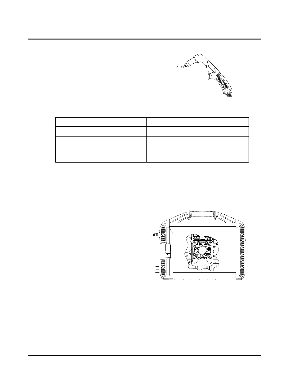
2
What to expect during and after cutting
Postflow – After you complete a cut and
release the torch trigger, air continues
to flow from the torch in order to cool
the consumables. This is referred to as
postflow.
The length of postflow depends on the
mode and the output current. Under
certain conditions, it also depends on
the gas supply.
Mode Output current Length of postflow
Cut 10–45A 20seconds
Gouge/marking 26 – 45 A 20 seconds
Gouge/marking 10 – 25 A 10 seconds for air (or nitrogen)
Operation
3 seconds for argon
Exception for argon: The system recognizes when argon is being used and reduces
postflow from 10 seconds to 3 seconds in order to minimize gas usage. To achieve 3-second
postflow, the system must be set to Gouge/Marking mode with the output current set
between 10 – 25 A. When the torch fires without transferring the pilot arc to the workpiece,
postflow is 10 seconds even when the supply gas is argon.
Fan activity – The cooling fan inside the
plasma power supply runs
intermittently during and after
cutting in order to cool internal
components.
Powermax45 XP Service Manual 809230 55

Operation
2
Warning puffs of air – When you set the
torch-disable switch to the “ready
to fire” ( ) position after the
torch has been locked, the torch
does not fire the first time you pull
the trigger. Instead, the torch emits
multiple puffs of air in quick
succession. With each puff of air,
the torch vibrates slightly, and the
power supply emits an audible
pressure-release sound. This
serves as a warning to alert you
that the torch is active and will fire
an arc the next time you pull the
trigger. See page 47.
For the machine torch, run a START/STOP command from the CNC to
cause the torch to emit the puffs of air. On the next start signal, the torch
will fire an arc.
The Torch Cap LED on the front panel illuminates when you
remove the consumables or set the torch-disable switch to the
yellow lock (X) position while the plasma power supply is still
ON. The LED extinguishes after you install the consumables
and set the torch-disable switch to the green “ready to
fire” ( ) position.
Adjust the gas pressure manually
The power supply automatically regulates the gas pressure for you. However, you can adjust the gas
pressure manually if you need to for a specific application.
Overriding the system’s gas pressure setting should be done only by
experienced users who need to optimize the gas setting for a specific
cutting application.
1. Select the mode, and set the
output current. In this
example, we selected
gouge/marking mode and set
the output current to 45 A.
Set the mode and
output current first
because doing so
can reset the gas
pressure. See
page 58.
56 809230 Service Manual Powermax45 XP

2
2. Press-and-hold the Mode
Press-and-hold the button while turning the knob.
button with one hand. Turn
the adjustment knob to the
desired gas pressure with the
other hand. In this example,
we turned down the gas
pressure to 35 psi.
As you manually
adjust the gas
pressure, the AMPS
LED turns off, and the
2-digit display
changes from
amperage to gas
pressure, as follows:
CSA models: The gas pressure displays in psi by default.
CE/CCC models: The gas pressure displays in bar by default.
You can change the display values for gas pressure. See page 59.
Operation
3. Release the Mode button.
After you release the
Mode button, the
AMPS LED
illuminates again, and
the 2-digit display
changes from gas
pressure back to
amperage.
The selected mode LED blinks to let you know that the gas pressure has been manually
adjusted. It continues to blink until you reset the pressure.
To view the gas pressure setting again, repeat step 2 above, or enter gas test mode.
See Run a gas test on page 158.
Powermax45 XP Service Manual 809230 57

Operation
2
Press the button to reset the gas pressure.
Reset the gas pressure
When you manually adjust the gas pressure, the pressure you set remains in place until you reset it.
You can reset the gas pressure by pressing the Mode button.
When you reset the gas pressure, the selected mode LED stops blinking.
The gas pressure also resets to the default setting when:
You are in gouge/marking mode and you change the output current from:
The Maximum Control gouging process (26 – 45 A) to the Precision gouging process
(10 – 25 A)
The Precision gouging process (10 – 25 A) to the Maximum Control gouging process
(26 – 45 A)
You connect a different torch to the power supply.
Turning the power supply OFF and ON does not reset the gas pressure.
58 809230 Service Manual Powermax45 XP

2
Change the gas pressure values between psi and bar
Press-and-hold for 15 seconds to toggle between psi and bar.
psi bar
CSA models: The gas pressure displays in psi by default.
CE/CCC models: The gas pressure displays in bar by default.
To change the gas pressure display values from psi to bar or from bar to psi:
1. Press-and-hold the Mode button for approximately 15 seconds until the 2-digit display
shows P.U.
Operation
2. Release the Mode button. The system will now display gas pressure values in bar instead of psi
or in psi instead of bar.
Powermax45 XP Service Manual 809230 59

Operation
2
Understand duty cycle to prevent overheating
Duty cycle – Percentage of time during a 10-minute interval that a plasma arc can remain on
without causing the system to overheat.
Output current Duty cycle*
45 A 50%
41 A 60%
32 A 100%
* Assumes ambient operating temperature of 40°C (104°F).
When you exceed the duty cycle and the system overheats:
The plasma arc shuts off.
The Temperature LED illuminates.
The cooling fan inside the power supply runs.
When the system overheats:
a. Leave the system on to allow the fan to cool the power supply.
b. Wait for the Temperature LED to turn off before you start to cut again.
Stretching the plasma arc for
prolonged periods negatively
impacts duty cycle. Whenever
possible, drag the torch on the
workpiece. See Start a cut from
the edge of the workpiece on
page 73.
If you operate the system on a
lower rated electrical service,
stretching the plasma arc for
prolonged periods can cause the
system to overheat more quickly
and can cause the circuit breaker
to trip. See Decrease output
current and arc stretch for lower
rated electrical service on
page 33.
60 809230 Service Manual Powermax45 XP

Cut with the Hand Torch
Duramax Lock hand torches come in 15° and 75° models.
The 75° hand torch is a general purpose torch designed for the widest range of applications.
The 15° hand torch is designed to direct heat away from the operator during heavy gouging.
It also facilitates cutting overhead or in hard to reach areas.
Duramax Lock torch features include:
A torch-disable switch that prevents the torch from firing accidentally even when the power
supply is ON. See Disable the torch on page 46.
The FastConnect
switch from one torch to another.
TM
quick-disconnect system to easily remove the torch for transport or to
Automatic cooling with ambient air. Special cooling procedures are not needed.
This section provides an overview of hand torch parts, dimensions, consumables, cutting guidelines,
and basic cutting methods. For gouging information, see Gouge with the Hand Torch and Machine
Tor ch on page 77.
To resolve issues with cut quality, refer to Troubleshooting guide on
page 172.
The Duramax Lock hand torches ship without consumables installed. To install the consumables,
see page 48.
Powermax45 XP Service Manual 809230 61

Cut with the Hand Torch
3
Consumables
Safety trigger
Torch-disable switch
260 mm (10.2 inch)
10 2 m m
(4.0 inch)
75°
61 mm (2.4 inch)
25 mm (1.0 inch)
69 mm
(2.7 inch)
269 mm (10.6 inch)
51 mm
(2.0 inch)
69 mm
(2.7 inch)
15°
325 mm (12.8 inch)
25 mm (1.0 inch)
Hand torch components, dimensions, weights
Components
Dimensions
75° hand torch
15° hand torch
62 809230 Service Manual Powermax45 XP

3
Weights
10 2 m m
4inch
10 2 m m
4inch
204 mm
8inch
Diameter = 2 x Radius = 204 mm (8 inches)
Torch We igh t
Hand torch with 6.1 m (20 foot) lead 1.8 kg (3.9 pounds)
Hand torch with 15 m (50 foot) lead 3.7 kg (8.1 pounds)
Minimum bend radius for torch leads
The recommended minimum bend radius for torch leads is 102 mm (4 inches).
Cut with the Hand Torch
Powermax45 XP Service Manual 809230 63

Cut with the Hand Torch
3
Choose the consumables
The 15° and 75° Duramax Lock hand torches use the same consumables.
Your system ships with a starter consumable kit that includes the shielded consumables on page 65
plus 1 extra electrode and 1 extra nozzle.
Consumable Type Purpose
Shielded drag-cutting Drag cut for the widest range of cutting applications.
FineCut
®
HyAccess
FlushCut
TM
TM
Achieve narrower kerf on thin mild steel and stainless steel up to
3mm (10gauge).
Cut or gouge in hard to reach areas or confined spaces.
Cut as close to the base as possible without piercing or
damaging the workpiece.
Maximum Control gouging (26 – 45 A)* Remove metal and achieve a controlled gouge profile.
Precision gouging (10 – 25 A)*
Marking (10 – 25 A)
* For details on gouging processes and consumables, see Gouging processes on page 77.
†
For details on marking consumables, see Marking consumables (10 – 25 A) on page 121.
†
Achieve very shallow gouge and lower metal removal rate than
with Maximum Control gouging, such as for spot weld removal.
Mark metal surfaces using air or argon.
When you use the following
shielded and FineCut
consumables, select Cut mode
on the front panel. See page 53.
64 809230 Service Manual Powermax45 XP

3
Shielded drag-cutting consumables
220818
Shield
220854
Retaining cap
220941
Nozzle
220857
Swirl ring
220842
Electrode
220931
Deflector
220854
Retaining cap
220930
Nozzle
220947
Swirl ring
220842
Electrode
420410
Cutting nozzle
420408
Electrode
220857
Swirl ring
420413
Retaining cap
FineCut consumables
Cut with the Hand Torch
Specialty consumables
HyAccess cutting consumables
HyAccess consumables extend the reach of the regular shielded consumables by approximately
7.5 cm (3 inches). Use them with your hand torch to achieve greater reach and visibility.
HyAccess gouging consumables are also available. See page 79.
You can expect to cut approximately the same thicknesses as with the regular shielded
consumables. You may need to reduce your cut speed slightly to achieve the same cut quality.
Typically, you can expect HyAccess consumables to last approximately half as long as the regular
shielded consumables.
Powermax45 XP Service Manual 809230 65

Cut with the Hand Torch
3
420633
Nozzle
420635
Electrode
420634
Swirl ring
420540
Retaining ring
420536
Cap
You can order each HyAccess consumable separately or in starter kits. When the tip of the nozzle
wears out, replace the entire nozzle.
The 428445 cutting starter kit contains:
1 HyAccess electrode
1 HyAccess cutting nozzle
1 HyAccess retaining cap
The 428414 cutting/gouging starter kit contains:
2 HyAccess electrodes
1 HyAccess cutting nozzle
1 HyAccess gouging nozzle
1 HyAccess retaining cap
1 swirl ring (standard Powermax45 XP swirl ring)
FlushCut™ consumables
FlushCut consumables are designed to remove lugs, pad eyes, and other attachments without
piercing or damaging the workpiece underneath. FlushCut consumables produce an angled plasma
arc that enables you to cut very close to the base material without leaving a large amount of residual
material to grind off.
You can expect to cut approximately the same thicknesses as with the regular shielded
consumables. However, make sure to account for any added thickness that may be present from
weld beads. Consumable life will vary, but typically you can expect FlushCut consumables to last
approximately 3/4 as long as the regular shielded consumables.
You can order FlushCut consumables individually or in a starter kit (428746) that contains 1 of each
consumable shown above. If you order FlushCut consumables individually:
The minimum order quantity for the electrode is 5.
All other FlushCut consumables can be ordered in single quantities.
66 809230 Service Manual Powermax45 XP

Cut with the Hand Torch
3
WARNING
ARC RAYS CAN BURN EYES AND SKIN
When you use FlushCut consumables, wear a face shield that covers your entire
face. Use a shield with a shade 10 lens.
Plasma arc rays produce intense visible and invisible (ultraviolet and infrared) rays
that can burn eyes and skin.
WARNING
INSTANT-ON TORCHES – PLASMA ARC CAN CAUSE INJURY, BURNS
Before rotating the FlushCut nozzle, one of the following actions must
be taken. Whenever possible, complete the first action.
Turn OFF (O) the plasma power supply.
OR
Move the torch-disable switch to the yellow lock (X) position
(closest to the torch lead). Pull the trigger to make sure the
torch does not fire a plasma arc.
To inst a l l :
1. Turn OF F (O) the power supply, or set the torch-disable switch to the yellow lock (X) position.
2. Put the swirl ring, electrode, cap, and nozzle on the torch. Rotate the
nozzle based on the direction you plan to cut. Make sure the flat side of
the nozzle is on the bottom so you can drag it along the workpiece.
3. Fully tighten the retaining ring onto the cap.
Repeat these steps while cutting if you need to change the orientation of
the nozzle in order to complete the cut.
Tips:
Drag the flat side of the nozzle along the base, but maintain a standoff of approximately
3 mm – 6 mm (1/8 inch to 1/4 inch) from the vertical workpiece you are cutting.
You can use the FlushCut consumables in Gouge/Marking mode to remove residual material
from the base workpiece. Turn down the amperage as needed.
Replace the cap when the outer sleeve no longer slides freely up
and down.
Powermax45 XP Service Manual 809230 67

Cut with the Hand Torch
3
220777
CopperPlus™ electrode
The CopperPlus electrode (220777) delivers at least
2 times longer consumable life over standard consumables
(Hypertherm consumables designed for the system). This
electrode is designed exclusively for use with Duramax and
Duramax Lock torches when cutting metal up to 12 mm
(1/2 inch).
Consumable life
Many factors influence how often you need to change the consumables on your hand torch:
Poor gas supply quality
It is extremely important to maintain a clean, dry gas line. The presence of oil, water,
vapor, and other contaminants in the gas supply can degrade cut quality and
consumable life. See page 37 and page 41.
Cutting technique
Whenever possible, start cuts from the edge of the workpiece. This helps to extend the
life of the shield and the nozzle. See page 73.
Use the proper piercing technique for the thickness of metal you are cutting. In many
instances, a rolling pierce technique is an efficient way to pierce the metal while
minimizing the consumable wear that naturally occurs during piercing. See page 74 for
an explanation of the straight pierce and rolling pierce techniques and when each is
appropriate.
Shielded versus non-shielded consumables
Non-shielded consumables use a deflector instead of a shield. They can provide better
visibility and accessibility for some cutting applications. The trade-off is that
non-shielded consumables generally have a shorter life than shielded consumables.
Thickness of metal being cut
In general, the thicker the metal being cut, the more quickly the consumables become
worn. For best results, do not exceed the thickness specifications for this system. See
page 24.
Expanded metal cutting
Expanded metal has a slotted or mesh pattern. Cutting expanded metal wears out
consumables more quickly because it requires a continuous pilot arc. A pilot arc occurs
when the torch is fired but the plasma arc is not in contact with the workpiece.
68 809230 Service Manual Powermax45 XP

Cut with the Hand Torch
3
Incorrect consumables for output current and mode
To optimize consumable life, make sure the consumables installed on the torch match
the selected mode and output current. For example:
Do not use gouging consumables when the system is set to Cut mode. See
page 53.
Do not set the output current between 26 A and 45 A with the Precision gouging
consumables installed.
Unnecessary arc stretch when cutting
To maximize consumable life, avoid stretching the arc when it is not necessary. Drag the
torch on the workpiece whenever possible. See page 72.
Insufficient arc stretch when gouging
A proper arc stretch while gouging maintains distance between the torch tip and the
molten metal that builds up during the gouge. See page 81.
An arc stretch of 19 – 25 mm (3/4 – 1 inch) is recommended for gouging with the
Maximum Control gouging consumables at 26 – 45 A.
An arc stretch of 10 – 11 mm (3/8 – 1/2 inch) is recommended for gouging with the
Precision gouging consumables at 10 A– 25 A.
As a general rule, the consumables last approximately 1 to 2 hours of actual “arc on” time for hand
cutting. However, consumable life can vary a lot based on the factors listed above.
Powermax45 XP Service Manual 809230 69

Cut with the Hand Torch
3
Prepare to fire the torch
INSTANT-ON TORCHES – PLASMA ARC CAN CAUSE INJURY, BURNS
The plasma arc ignites immediately when you pull the torch trigger.
Before changing consumables, one of the following actions must be
taken. Whenever possible, complete the first action.
The plasma arc will cut quickly through gloves and skin.
WARNING
Turn OFF (O) the plasma power supply.
OR
Move the torch-disable switch to the yellow lock (X) position
(closest to the torch lead). Pull the trigger to make sure the
torch does not fire a plasma arc.
Wear correct and appropriate protective equipment.
Keep hands, clothing, and objects away from the torch tip.
Do not hold the workpiece. Keep your hands clear of the
cutting path.
Never point the torch toward yourself or others.
WARNING
RISK OF BURNS AND ELECTRIC SHOCK – WEAR INSULATED GLOVES
Always wear insulated gloves when changing the consumables. The
consumables get very hot during cutting and can cause severe burns.
Touching the consumables can also result in electric shock if the power
supply in ON and the torch-disable switch is not in the yellow lock (X)
position.
To prevent accidental firing, the hand torch is equipped with a torch-disable switch and a safety
trigger. To fire the torch:
1. Install the correct consumables. See page 48.
70 809230 Service Manual Powermax45 XP

3
2. Make sure the torch-disable switch is
1
2
3
in the green “ready to fire” ( )
position.
The first time you pull the
torch trigger after you set the
torch to the “ready to fire”
position, the torch may emit
multiple puffs of air in quick
succession. This warns you
that the torch is active and
will fire an arc the next time
the trigger is pulled.
Seepage47.
3. Flip the trigger’s safety cover forward
(toward the torch head) and press
the red torch trigger.
Cut with the Hand Torch
Powermax45 XP Service Manual 809230 71
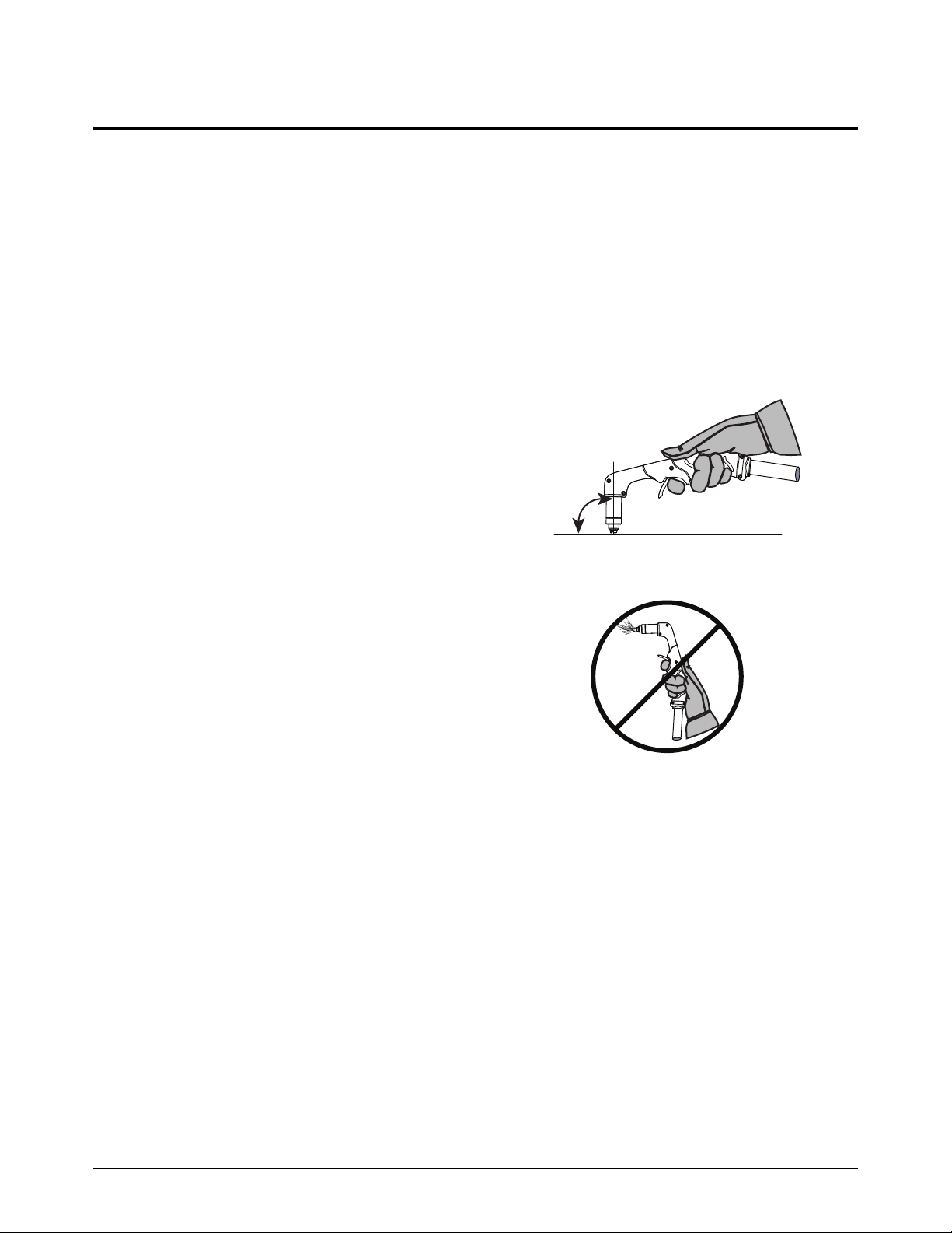
Cut with the Hand Torch
3
90°
Hand torch cutting guidelines
Drag the torch tip lightly along the workpiece to maintain a steady cut.
Sometimes the torch sticks slightly to the workpiece when you cut with
FineCut consumables.
Pulling, or dragging, the torch along the cut is easier than pushing it.
If sparks spray up from the workpiece, move the torch more slowly, or set the output current
higher.
While cutting, make sure that sparks exit from the bottom of the workpiece. The sparks
should lag slightly behind the torch as you cut (15° – 30° angle from vertical).
Hold the torch tip perpendicular to the
workpiece so that the head of the
torch is at a 90° angle to the cutting
surface. Observe the cutting arc as the
torch cuts.
If you fire the torch unnecessarily, you
will shorten the life of the nozzle and
electrode.
For straight-line cuts, use a straight
edge as a guide. To cut circles, use a
template or a radius cutter attachment
(a circle cutting guide). For beveled
cuts, use a bevel cutting guide. See
Accessory parts on page 332.
To troubleshoot issues with cut quality, see Troubleshooting guide on
page 172.
72 809230 Service Manual Powermax45 XP

3
Start a cut from the edge of the workpiece
Edge starting, when possible, is a good way to reduce damage to the shield and nozzle that can be
caused by the slag produced during piercing. This helps to optimize consumable life.
1. With the work clamp attached to the workpiece, hold the torch tip perpendicular (90°) to the
edge of the workpiece.
Cut with the Hand Torch
2. Press the torch’s trigger to start the arc. Pause at the edge until the arc has cut completely
through the workpiece.
3. Drag the torch lightly across the workpiece to proceed with the cut. Maintain a steady, even
pace.
Powermax45 XP Service Manual 809230 73

Cut with the Hand Torch
3
30° for rolling pierce
Pierce a workpiece
SPARKS AND HOT METAL CAN INJURE EYES AND BURN SKIN
When firing the torch at an angle, sparks and hot metal will spray out from the
nozzle. Point the torch away from yourself and others. Always wear proper protective
equipment including gloves and eye protection.
The hand torch can pierce interior features on metal with a thickness of up to 12 mm (1/2 inch).
The type of pierce to perform depends on the thickness of the metal.
Straight pierce – To cut metal that is thinner than 8 mm (5/16 inch).
Rolling pierce – To cut metal that is 8 mm (5/16 inch) or thicker.
1. Attach the work clamp to the workpiece.
WARNING
2. Straight pierce: Hold the torch perpendicular (90°) to the workpiece.
Rolling pierce: Hold the torch at an approximate 30° angle to the workpiece with the torch tip
within 1.5 mm (1/16 inch) of the workpiece before firing the torch.
74 809230 Service Manual Powermax45 XP

Cut with the Hand Torch
3
3. Straight pierce: Press the torch trigger to start the arc.
Rolling pierce: Press the torch trigger to start the arc while still at an angle to the workpiece,
then rotate the torch to the perpendicular (90°) position.
4. Hold the torch in place while continuing to press the trigger. When sparks exit below the
workpiece, the arc has pierced the material.
5. When the pierce is complete, drag the torch tip lightly along the workpiece to proceed with the
cut.
Powermax45 XP Service Manual 809230 75

Cut with the Hand Torch
3
76 809230 Service Manual Powermax45 XP

Gouge with the Hand Torch and Machine Torch
Make sure the Gouge/Marking Mode LED is illuminated.
Gouging processes
This system offers 2 gouging processes. Each process uses its own set of consumables:
Maximum Control gouging
Use this process to remove metal and to achieve a controlled gouge profile.
Precision gouging
Use this process to achieve a very shallow gouge and a lower metal removal rate than
with Maximum Control gouging. For example, this process is useful for removing spot
welds and for washing material at very low depths.
Before you use either process, press the Mode button on the front panel to set the plasma power
supply to Gouge/Marking mode. See page 53.
Powermax45 XP Service Manual 809230 77

Gouge with the Hand Torch and Machine Torch
4
420419
Nozzle
420480
Shield
220854
Retaining cap
220857
Swirl ring
220842
Electrode
220854
Retaining cap
420415
Nozzle
220857
Swirl ring
220842
Electrode
420414
Deflector
Maximum Control gouging
Use the Maximum Control gouging consumables.
Hypertherm also offers Maximum Removal gouging consumables. At
higher amperages on other Powermax systems, you can use the Maximum
Removal consumables for greater metal removal rate and deeper gouge
profiles. However, at 45 A with this system and torch, the Maximum
Removal consumables do not offer an advantage over the Maximum
Control consumables in terms of metal removal rate. You can expect each
set of consumables to produce similar results on this system.
Set the output current between 26 A and 45 A.
Gouging at lower amperages (10 – 25 A) can limit the torch’s arc stretch capability. In
some instances it may also cause the arc to extinguish or trigger a “torch stuck open”
(TSO) fault. See page 171.
Maximum Control gouging consumables (26 – 45 A)
Precision gouging
Use the Precision gouging consumables.
Set the output current between 10 A and 25 A.
Gouging at higher amperages (26 – 45 A) can shorten the life of the nozzle.
Precision gouging consumables (10 – 25 A)
78 809230 Service Manual Powermax45 XP

4
Specialty consumables
420412
Gouging nozzle
420408
Electrode
220857
Swirl ring
420413
Retaining cap
HyAccess gouging consumables
HyAccess consumables extend the reach of the regular shielded consumables by approximately
7.5 cm (3 inches). Use them with your hand torch to achieve greater reach and visibility.
HyAccess cutting consumables are also available. For more information
on HyAccess consumables, see page 65.
Gouge with the Hand Torch and Machine Torch
You can order each HyAccess consumable separately or in starter kits. When the tip of the nozzle
wears out, replace the entire nozzle.
The 428446 gouging starter kit contains:
1 HyAccess electrode
1 HyAccess gouging nozzle
1 HyAccess retaining cap
The 428414 cutting/gouging starter kit contains:
2 HyAccess electrodes
1 HyAccess cutting nozzle
1 HyAccess gouging nozzle
1 HyAccess retaining cap
1 swirl ring (standard Powermax45 XP swirl ring)
Powermax45 XP Service Manual 809230 79

Gouge with the Hand Torch and Machine Torch
4
Standoff
Angle
Rotation of torch (relative
to torch center line)
Torch center line
Speed
How to control the gouge profile
The following factors affect the width and the depth of the gouge profile. Adjust these elements to
achieve the gouge you need.
Output current of the plasma power supply – Turn down the amperage on the front panel
to make the gouge narrower and more shallow.
If you are using the Maximum Control gouging consumables, keep the amperage
between 26 – 45 A.
If you are using the Precision gouging consumables, keep the amperage between
10 – 2 5 A .
Angle of the torch to the workpiece – Position the torch in a more upright position to
make the gouge narrower and deeper. Tilt down the torch so that it is closer to the
workpiece to make the gouge wider and more shallow.
Rotation of the torch – Rotate the torch relative to the torch center line to make the gouge
flatter and steeper on one side.
Torch-to-work standoff – Move the torch further away from the workpiece to make the
gouge wider and more shallow. Move the torch closer to the workpiece to make the gouge
narrower and deeper.
Speed of the torch over the workpiece – Slow down to make the gouge wider and
deeper. Speed up to make the gouge narrower and more shallow.
80 809230 Service Manual Powermax45 XP

4
Gouge with the hand torch
40°
SPARKS AND HOT METAL CAN INJURE EYES AND BURN SKIN
When firing the torch at an angle, sparks and hot metal will spray out from the
nozzle. Point the torch away from yourself and others. Always wear proper protective
equipment including gloves and eye protection.
1. Install the Maximum Control gouging consumables or the Precision gouging consumables.
2. Set the system to Gouge/Marking mode. See page 53.
3. Set the output current to match the consumables installed:
Maximum Control gouging consumables: 26 – 45 A
Precision gouging consumables: 10 – 25 A
Gouge with the Hand Torch and Machine Torch
WARNING
4. Hold the torch at approximately a 40° angle to the workpiece before firing the torch.
Maximum Control gouging consumables: Hold the torch approximately 6 mm (1/4 inch)
above the workpiece.
Precision gouging consumables: Hold the torch approximately 2 – 3 mm above the
workpiece.
Press the trigger to obtain a pilot arc. Transfer the arc to the workpiece.
5. Stretch the arc as follows:
Maximum Control gouging consumables: 19 – 25 mm (3/4 – 1 inch)
Precision gouging consumables: 10 – 11 mm (3/8 – 1/2 inch)
Powermax45 XP Service Manual 809230 81

Gouge with the Hand Torch and Machine Torch
4
Direction of
travel
6. Change the torch’s angle as needed to achieve the desired dimensions for the gouge. Maintain
the same angle to the workpiece as you feed into the gouge. Push the plasma arc in the
direction of the gouge you want to create.
Keep at least a small distance between the torch tip and the molten metal
to avoid reducing consumable life or damaging the torch.
Remove spot welds
To remove a spot weld, gouge around the weld in order to cut completely through the top layer of
metal without damaging the layer underneath.
The Precision gouging consumables were designed specifically for applications like removing spot
welds. When used at a lower amperage, these consumables provide:
Very good visibility due to a plasma arc that is less bright and that allows you to see the
metal being gouged more clearly
A very high width-to-depth ratio, which provides much better control of the metal removal
rate
Tips
Many different techniques can be used to remove spot welds. The method described in the
following procedure is recommended as a good starting point. It is intended to minimize possible
damage to the underneath layer.
Regardless of technique, these tips can help you to successfully remove spot welds:
Keep the torch pointed in the same direction all the way around the spot weld.
By keeping the torch pointed in the same direction, you avoid blowing slag over areas
you already gouged. This reduces the clean-up needed on the underneath layer. It also
makes the process more ergonomic and efficient, since you do not need to rotate the
torch or the workpiece while gouging.
Maintain a proper arc stretch.
Maintain an arc stretch of approximately 10 – 11 mm (3/8 – 1/2 inch) as you gouge
around the weld. This provides good visibility and prevents the torch tip from hitting slag,
which can shorten consumable life and interrupt the gouge.
82 809230 Service Manual Powermax45 XP

Gouge with the Hand Torch and Machine Torch
4
40° – 45°
Spot weld
40° – 45°
Left-handed approach Right-handed approach
Start at a lower output current, and gradually increase it.
Start with the current set to 10 A if you have never removed a spot weld before. Once
you develop a technique you are comfortable with, try gradually increasing the output
current. This enables you to gouge with better speed and efficiency.
Procedure
This procedure describes how to separate 2 metal layers and then remove the spot weld from the
underneath layer.
The pictures in this procedure show mild steel plates. The slag on
stainless steel is darker, more jagged, and harder to remove.
1. Install the Precision gouging consumables.
2. On the front panel, select Gouge/Marking mode. Set the output current to 10 – 25 A.
3. Position the torch on one side of the spot weld. Hold the torch at approximately a 40° – 45°
angle to the workpiece.
4. Press the trigger to obtain a pilot arc. Transfer the arc to the workpiece, then stretch the arc to
approximately 10–11mm (3/8–1/2inch). Maintain this arc as you gouge.
5. Make 2 separate gouges in an “L”-shaped motion to gouge all the way around the spot weld.
See Table 1 on page 84.
Table 1 shows one example of this technique (for both right-handed and left-handed
gouging). You can start at different points around the spot weld. The important thing is
to keep the torch pointed in the same direction all the way around the weld.
As you gouge, use very short strokes in a back-and-forth weaving motion until you have
cut through the top layer.
You may need to adjust the angle of the torch slightly, depending on the thickness of the
metal.
Powermax45 XP Service Manual 809230 83
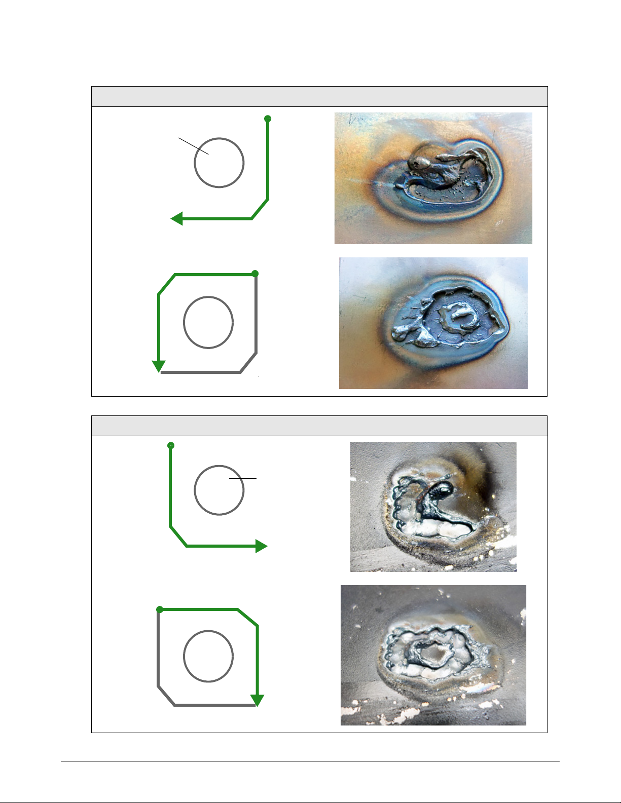
Gouge with the Hand Torch and Machine Torch
4
Spot weld
Start
Stop
Start
Stop
Spot weld
Start
Stop
Start
Stop
Tabl e 1 – Gouging around the spot weld
Right-handed approach
Left-handed approach
84 809230 Service Manual Powermax45 XP

4
6. Make sure you have gouged
completely through the top layer. Pull
the metal plates apart.
7. Use the same gouging process to
remove the spot weld that remains on
the bottom plate.
To avoid damaging the
bottom plate, you may want
to turn down the output
current to 10 A. Increase the
current if needed based on
the thickness of the metal.
Hold the torch at a 40° – 45°
angle. Slightly adjust the
angle of the torch as needed based on the thickness of the metal.
Stretch the arc to approximately 10 – 11 mm (3/8 – 1/2 inch) as you gouge.
Use very short strokes in a back-and-forth weaving motion until you have removed the
spot weld.
Gouge with the Hand Torch and Machine Torch
Some scraping or grinding may be required to completely remove all
remnants of the spot weld from the bottom plate.
Spot weld on bottom plate Spot weld removed
Powermax45 XP Service Manual 809230 85

Gouge with the Hand Torch and Machine Torch
4
Standoff
Angle
Rotation of torch (relative
to torch center line)
Torch center line
Speed
Gouge with the machine torch
You can vary the gouge profile by adjusting the:
Output current (amperage) of the power supply
Angle of the torch to the workpiece
Rotation of the torch relative to the torch center line
Torch-to-work st a n d off
Speed of the torch over the workpiece
See page 80 for more details.
86 809230 Service Manual Powermax45 XP

4
Typical gouge profiles
Depth
3.2 mm (0.1 inch)
Width
6.8 mm (0.3 inch)
Maximum Control gouging consumables (45 A)
Operating parameters
Speed 254–1016mm/min (10–40in/min)
Standoff 6mm (1/4inch)
Angle 40° – 50°
Output current 26 – 45 A
Consumables Maximum Control gouging consumables
Gas Air
45 A
Metal removal rate on mild steel:
3.4 kg/hour (7.5 pounds/hour)
Gouge with the Hand Torch and Machine Torch
The following tables show the 45 A gouging profile at 40° and 50° on mild steel and stainless steel.
These settings are intended to serve as a starting point to help you determine the best gouging
profile for a given cutting job. Adjust these settings as needed for your application and table to
obtain the desired result.
Tabl e 2 – Mild steel (Metric)
Torch angle Speed (mm/min) Depth (mm) Width (mm) Width/depth ratio
254 4.6 8.4 1.83
508 3.2 6.8 2.13
40°
50°
762 1.9 5.9 3.11
1016 1.4 5.2 3.71
254 5.0 6.7 1.34
508 3.4 5.2 1.53
762 2.7 4.9 1.81
1016 2.2 4.6 2.09
Powermax45 XP Service Manual 809230 87

Gouge with the Hand Torch and Machine Torch
4
Tabl e 3 – Mild steel (English)
Torch angle Speed (in/min) Depth (inches) Width (inches) Width/depth ratio
10 0.183 0.331 1.81
20 0.126 0.268 2.13
40°
30 0.074 0.231 3.12
40 0.055 0.206 3.74
10 0.195 0.263 1.35
50°
Tabl e 4 – Stainless steel (Metric)
Torch angle Speed (mm/min) Depth (mm) Width (mm) Width/depth ratio
40°
50°
Tabl e 5 – Stainless steel (English)
Torch angle Speed (in/min) Depth (inches) Width (inches) Width/depth ratio
20 0.132 0.205 1.55
30 0.107 0.192 1.79
40 0.088 0.181 2.06
254 2.9 6.2 2.14
508 2.0 5.7 2.85
101 6 1 4.8 4 .8
254 5.3 5.7 1.08
508 3.5 5.0 1.43
1016 2.0 3.8 1.90
10 0.114 0.245 2.15
40°
50°
88 809230 Service Manual Powermax45 XP
20 0.080 0.222 2.76
40 0.048 0.190 3.96
10 0.210 0.224 1.07
20 0.139 0.199 1.43
40 0.080 0.150 1.88

4
Precision gouging consumables (10 A)
Depth
0.5mm (0.02inch)
Width
2.5 mm (0.1 inch)
Speed 254–762mm/min (10–30in/min)
Standoff 0.3–1.3mm (0.01–0.05inch)*
Angle 40° – 50°
Output current 10 – 2 5 A
Consumables Precision gouging consumables
Gas Air
* Increase the standoff to a maximum of 3 – 4 mm (0.12 – 0.16 inch) for a very light gouge.
10 A
Metal removal rate on mild steel:
0.2 kg/hour (0.5 pounds/hour)
Gouge with the Hand Torch and Machine Torch
Operating parameters
The following tables show the 10 A gouging profile at 40° and 50° on mild steel. These settings are
intended to serve as a starting point to help you determine the best gouging profile for a given
cutting job. Adjust these settings as needed for your application and table to obtain the desired
result.
Tabl e 6 – Mild steel (Metric)
Torch angle Standoff (mm)
0.3 254 0.5 3.3 6.6
0.3 508 0.3 2.4 8
0.3 762 0.1 2.2 22
40°
1.3 254 0.3 3 10
1.3 508 0.1 2.2 22
1.3 762 0.05 1.9 38
Speed
(mm/min)
Depth (mm) Width (mm)
Width/depth
ratio
Powermax45 XP Service Manual 809230 89

Gouge with the Hand Torch and Machine Torch
4
Torch angle Standoff (mm)
0.3 254 1.1 2.6 2.36
0.3 508 0.6 2.3 3.83
0.3 762 0.4 2.0 5
50°
Tabl e 7 – Mild steel (English)
Torch angle
40°
1.3 254 1.1 2.8 2.55
1.3 508 0.5 2.4 4.8
1.3 762 0.25 2.1 8.4
Standoff
(inches)
0.01 10 0.0207 0.129 6.23
0.01 20 0.0113 0.095 8.41
0.01 30 0.0044 0.088 20
0.05 10 0.0122 0.12 9.84
Speed
(mm/min)
Speed (in/min) Depth (inches) Width (inches)
Depth (mm) Width (mm)
Width/depth
ratio
Width/depth
ratio
50°
0.05 20 0.004 0.088 22
0.05 30 0.002 0.074 37
0.01 10 0.0427 0.103 2.41
0.01 20 0.0222 0.09 4.05
0.01 30 0.0147 0.08 5.44
0.05 10 0.043 0.11 2.56
0.05 20 0.0208 0.095 4.57
0.05 30 0.01 0.084 8.4
90 809230 Service Manual Powermax45 XP

4
Troubleshooting tips for gouging
When gouging, always make sure:
Gouging consumables are installed, and the output current matches those consumables.
The power supply is set to Gouge/Marking mode.
Many common metal removal issues can be resolved by installing new consumables in the torch. Do
not use worn or damaged consumables.
Problem Solution
Gouge with the Hand Torch and Machine Torch
The arc goes out during
gouging.
The torch tip bumps into
slag.
The gouge is too deep. • Decrease the angle of the torch to the workpiece.
The gouge is too shallow. • Increase the angle of the torch to the workpiece.
The gouge is too wide. • Increase the angle of the torch to the workpiece.
• Decrease the arc stretch (standoff).
• Increase the angle of the torch to the workpiece.
• Increase the arc stretch (standoff).
• Keep the torch tip pointed in the direction of the gouge you want to create.
• Increase the arc stretch (standoff).
• Increase the gouging speed.
• Decrease the output current. Do not set the output current below 26 A if you are
using the Maximum Control gouging consumables.
• Decrease the arc stretch (standoff).
• Decrease the gouging speed.
• Increase the output current. Do not set the output current above 25 A if you are
using the Precision gouging consumables.
• Decrease the arc stretch (standoff).
• Increase the gouging speed.
• Decrease the output current. Do not set the output current below 26 A if you are
using the Maximum Control gouging consumables.
The gouge is too narrow. • Decrease the angle of the torch to the workpiece.
• Increase the arc stretch (standoff).
• Decrease the gouging speed.
• Increase output current. Do not set the output current above 25 A if you are using
the Precision gouging consumables.
Powermax45 XP Service Manual 809230 91

Gouge with the Hand Torch and Machine Torch
4
Problem Solution
When removing a spot
weld, the arc pierces the
bottom metal plate.
The spot weld is not
visible while gouging.
• Decrease the output current (amperage).
• Make sure the Precision gouging consumables are installed.
• Maintain a steady gouging speed and gouge only until the bottom metal plate is
visible.
• Increase the arc stretch to approximately 10 – 11 mm (3/8 – 1/2 inch).
• Stretch the arc to approximately 10 – 11 mm (3/8 – 1/2 inch) for better visibility
of the spot weld.
• Make sure the Precision gouging consumables are installed.
• Make sure the output current is not set above 25 A.
92 809230 Service Manual Powermax45 XP

Set Up the Machine Torch
Duramax Lock machine torch features include:
A torch-disable switch that prevents the torch from firing accidentally even when the power
supply is ON. See Disable the torch on page 46.
The FastConnect
switch from one torch to another.
Automatic cooling with ambient air. Special cooling procedures are not needed.
This section provides information on:
Machine torch components and dimensions
Setup details for installing the torch on X-Y tables, track burners, pipe bevelers, or other
mechanized equipment
TM
quick-disconnect system to easily remove the torch for transport or to
Powermax45 XP Service Manual 809230 93

Set Up the Machine Torch
5
1
2
3
5
6
4
7
1 Consumables
2 32-pitch removable gear rack
3 Torch-disable switch
4 To r ch lead
5 Shell
6 Switch position lines
7 Strain relief for torch lead
33 mm
(1.3 inch)
310 mm (12.2 inch)
370 mm (14.6 inch)
35 mm*
(1.4 inch)
212 mm (8.4 inch)
25 mm
(1.0 inch)
Machine torch components, dimensions, weights
Components
Dimensions
* This measurement is for the outer dimension of the torch. The height of the outer torch shell is 41 mm
(1.6 inch) when the torch-disable switch is included.
94 809230 Service Manual Powermax45 XP

5
Weights
10 2 m m
4inch
10 2 m m
4inch
204 mm
8inch
Diameter = 2 x Radius = 204 mm (8 inches)
Torch We igh t
Machine torch with 7.6 m (25 foot) lead 3.2 kg (7.1 pounds)
Machine torch with 10.7 m (35 foot) lead 4.2 kg (9.3 pounds)
Machine torch with 15 m (50 foot) lead 5.8 kg (12.7 pounds)
Minimum bend radius for torch leads
The recommended minimum bend radius for torch leads is 102 mm (4 inches).
Set Up the Machine Torch
Mount the torch
The machine torch can be mounted on a wide variety of X-Y tables, track burners, pipe bevelers, and
other equipment. Install the torch per the table or equipment manufacturer’s instructions.
If your cutting table’s track is large enough for you to route the torch through it without removing the
torch shell, do so and then attach the torch to the lifter per the manufacturer’s instructions.
Remove the gear rack
The gear rack can be mounted on either side of the torch. If you need to remove the gear rack,
remove the 2 screws that secure the rack to the torch shell.
Powermax45 XP Service Manual 809230 95

Set Up the Machine Torch
5
Gear rack
When you install the gear rack, tighten the screws by hand. To avoid
stripping the screws, do not overtighten.
Disassemble the machine torch
Use the following procedure if you need to disassemble the torch to route the torch through the
cutting table’s track or other mounting system.
NOTICE
While disconnecting and reconnecting the torch parts, do not twist the torch or the lead.
Maintain the same orientation between the torch head and torch lead. Twisting the torch head in
relation to the torch lead can damage the torch wires.
1. Disconnect the torch from the plasma power supply.
2. Remove the consumables from the torch.
3. Place the torch on a flat surface with the left side of the shell facing up.
The left side of the shell is the side with the screws.
4. Remove the 7 screws from the torch shell. Set the screws aside.
96 809230 Service Manual Powermax45 XP

Set Up the Machine Torch
5
1
1
5. Carefully pry the left side of the shell away from the torch.
6. Remove the plastic slider for the torch-disable switch and set it aside.
7. The torch body fits snugly into the right side of the shell. Gently pry the head of the torch body
out and away from the right side of the shell to remove it.
8. Disconnect the wires that sit in the right shell. Press down the tab on the wire connector to pull
the 2 sides apart.
9. You can now route the torch body and the torch lead through the mounting system for the
cutting table.
Slide the strain relief along the torch lead as needed to move it out of the
way as you route the torch lead through the track.
Powermax45 XP Service Manual 809230 97

Set Up the Machine Torch
5
1
2
1
2
3
4
3
4
5
5
Assemble the machine torch
If you disassembled the torch to route it through the cutting table’s track or other mounting system,
use the following procedure to reassemble the torch.
While disconnecting and reconnecting the torch parts, do not twist the
torch or the lead. Maintain the same orientation between the torch head
and torch lead. Twisting the torch head in relation to the torch lead can
cause damage to the torch wires.
1. Place the right torch shell on a flat surface.
2. Make sure the cap-sensor switch and the torch-disable switch sit in the right torch shell as
shown. Mounting posts in the torch shell hold each switch in place.
3. Connect the wires from the torch body to the wires from the cap-sensor switch/torch-disable
switch assembly .
4. Place the wire connector on the mounting shelf in the right torch shell as shown.
Route the blue and black wires from the cap-sensor switch and the torch-disable switch outside
of and below the mounting shelf. This helps to prevent the wires from getting pinched and
damaged when the torch is fully assembled.
98 809230 Service Manual Powermax45 XP

Set Up the Machine Torch
5
6
6
5. Push the head of the torch body into the right torch shell as shown. Make sure:
The torch shell fits over the flat edges of the torch head. The rounded edge of the torch
head should be facing up.
The wire connector from the previous step remains in place on the mounting shelf. Hold
the wire connector in place as you fit the torch body into the torch shell.
6. Fit the rest of the torch body into the right torch shell as shown. As you do, tuck all of the wires
under the torch body. Do not pinch or crimp the wires. Make sure none of the wires are covering
the screw holes in the torch shell.
7. Fit the strain relief into the base of the right torch shell.
8. Put the plastic slider for the
torch-disable switch into place in the
yellow lock (X) position.
If you try to put the torch back
together with the slider in the
green “ready to fire” ( )
position, you can damage the
torch-disable switch that is
inside the shell behind the
torch body.
Powermax45 XP Service Manual 809230 99

Set Up the Machine Torch
5
1
90°
1
9. Attach the left torch shell to the right torch shell using the 7 screws. Firmly grasp the torch shells
at the base near the strain relief and hold them together as you install the screws.
NOTICE
Be careful to avoid pinching the wires between the torch shells. This can damage the wires and
prevent the torch from operating properly.
10. Examine the torch to make sure no wires are pinched where the torch shells meet.
11 . Install the gear rack on the torch shell.
12. Attach the torch to the lifter per the manufacturer’s instructions.
13. Reinstall the consumables on the torch. See page 48.
Align the torch
Mount the machine torch
perpendicular to the workpiece to
get a vertical cut. Use a square to
align the torch at a 90° angle to
the workpiece.
Position the mounting bracket
lower on the torch to minimize
vibration at the tip of the torch.
Do not overtighten the
mounting bracket. Excessive
pressure from the clamp can
warp or damage the torch shell
over time.
100 809230 Service Manual Powermax45 XP
 Loading...