


Powermax30®AIR
Plasma Arc Cutting System with Integrated Air Compressor
Operator Manual
808840 | Revision 5 | English

Register your new Hypertherm system
Benefits of registration
5 Safety: Registration allows us to contact you in the unlikely event a safety or quality notification
is required.
5 Education: Registration gives you free access to online product training content via the
Hypertherm Cutting Institute.
5 Confirmation of ownership: Registration can serve as proof of purchase in case of an
insurance loss.
Go to www.hypertherm.com/registration for easy and fast registration.
If you experience any problems with the product registration process, please contact
registration@hypertherm.com.
For your records
Serial number: __________________________________________________________________________
Purchase date: __________________________________________________________________________
Distributor: _____________________________________________________________________________
_______________________________________________________________________________________
_______________________________________________________________________________________
Maintenance notes: ______________________________________________________________________
_______________________________________________________________________________________
_______________________________________________________________________________________
_______________________________________________________________________________________
_______________________________________________________________________________________
Powermax and Hypertherm are trademarks of Hypertherm, Inc. and may be registered in the United States and other countries. All
other trademarks are the property of their respective holders.
Environmental stewardship is one of Hypertherm’s core values, and it is critical to our success and our customers’ success. We are
striving to reduce the environmental impact of everything we do. For more information:www.hypertherm.com/environment.
© 2022 Hypertherm, Inc.

Powermax30 AIR
Operator Manual
808840
Revision 5
English
April 2022
Hypertherm, Inc.
Hanover, NH 03755 USA
www.hypertherm.com

Hypertherm, Inc.
21 Great Hollow Road, P.O. Box 5010
Hanover, NH 03755 USA
603-643-3441 Tel (Main Office)
603-643-5352 Fax (All Departments)
info@hypertherm.com (Main Office)
800-643-9878 Tel (Technical Service)
technical.service@hypertherm.com (Technical Service)
800-737-2978 Tel (Customer Service)
customer.service@hypertherm.com (Customer Service)
Hypertherm México, S.A. de C.V.
52 55 5681 8109 Tel
52 55 5681 7978 Tel
soporte.tecnico@hypertherm.com (Technical Service)
Hypertherm Plasmatechnik GmbH
Sophie-Scholl-Platz 5
63452 Hanau
Germany
00 800 33 24 97 37 Tel
00 800 49 73 73 29 Fax
31 (0) 165 596900 Tel (Technical Service)
00 800 4973 7843 Tel (Technical Service)
technicalservice.emeia@hypertherm.com (Technical Service)
Hypertherm (Singapore) Pte Ltd.
Solaris @ Kallang 164
164 Kallang Way #03-13
Singapore 349248, Republic of Singapore
65 6841 2489 Tel
65 6841 2490 Fax
marketing.asia@hypertherm.com (Marketing)
techsupportapac@hypertherm.com (Technical Service)
Hypertherm Japan Ltd.
Level 9, Edobori Center Building
2-1-1 Edobori, Nishi-ku
Osaka 550-0002 Japan
81 6 6225 1183 Tel
81 6 6225 1184 Fax
htjapan.info@hypertherm.com (Main Office)
techsupportapac@hypertherm.com (Technical Service)
Hypertherm Europe B.V.
Vaartveld 9, 4704 SE
Roosendaal, Nederland
31 165 596907 Tel
31 165 596901 Fax
31 165 596908 Tel (Marketing)
31 (0) 165 596900 Tel (Technical Service)
00 800 4973 7843 Tel (Technical Service)
technicalservice.emeia@hypertherm.com (Technical Service)
Hypertherm (Shanghai) Trading Co., Ltd.
B301, 495 ShangZhong Road
Shanghai, 200231
PR China
86-21-80231122 Tel
86-21-80231120 Fax
86-21-80231128 Tel (Technical Service)
techsupport.china@hypertherm.com (Technical Service)
South America & Central America: Hypertherm Brasil Ltda.
Rua Bras Cubas, 231 – Jardim Maia
Guarulhos, SP – Brasil
CEP 07115-030
55 11 2409 2636 Tel
tecnico.sa@hypertherm.com (Technical Service)
Hypertherm Korea Branch
#3904. APEC-ro 17. Heaundae-gu. Busan.
Korea 48060
82 (0)51 747 0358 Tel
82 (0)51 701 0358 Fax
marketing.korea@hypertherm.com (Marketing)
techsupportapac@hypertherm.com (Technical Service)
Hypertherm Pty Limited
GPO Box 4836
Sydney NSW 2001, Australia
61 7 3103 1695 Tel
61 7 3219 9010 Fax
au.sales@hypertherm.com (Main Office)
techsupportapac@hypertherm.com (Technical Service)
Hypertherm (India) Thermal Cutting Pvt. Ltd
A-18 / B-1 Extension,
Mohan Co-Operative Industrial Estate,
Mathura Road, New Delhi 110044, India
91-11-40521201/ 2/ 3 Tel
91-11 40521204 Fax
htindia.info@hypertherm.com (Main Office)
technicalservice.emeia@hypertherm.com (Technical Service)
For training and education resources, go to the Hypertherm Cutting Institute (HCI) online at
www.hypertherm.com/hci.

ENGLISH
WARNING! Before operating any Hypertherm equipment, read the safety
instructions in your product’s manual, the Safety and Compliance Manual (80669C),
Waterjet Safety and Compliance Manual (80943C), and Radio Frequency Warning
Manual (80945C). Failure to follow safety instructions can result in personal injury
or in damage to equipment.
Copies of the manuals can come with the product in electronic and printed formats.
Electronic copies are also on our website. Many manuals are available in multiple
languages at www.hypertherm.com/docs.
FR (FRANÇAIS/FRENCH)
AVERTISSEMENT! Avant d’utiliser tout équipement Hypertherm, lire les consignes
de sécurité dumanuel de votre produit, duManuel de sécurité et de conformité
(80669C), du Manuel de sécurité et de conformité du jet d’eau (80943C)
et du Manuel d'avertissement relatif aux radiofréqunces (80945C).
Les exemplaires des manuels qui accompagnent le produit peuvent être sous forme
électronique ou papier. Les manuels sous forme électronique se trouvent également
sur notre site Internet. Plusieurs manuels sont offerts en plusieurs langues
à www.hypertherm.com/docs.
BG (БЪЛГAPCКИ/BULGARIAN)
ПРЕДУПРЕЖДЕНИЕ! Преди да работите с което и да е оборудване
Hypertherm, прочетете инструкциите за безопасност в ръководството на вашия
продукт, „Инструкция за безопасност и съответствие“ (80669C), „Инструкция
за безопасност и съответствие на Waterjet“ (80943С) и „Инструкция
за предупреждение за радиочестота“ (80945С).
Продуктът може да е съпроводен от копия на ръководствата в електронен
и в печатен формат. Тези в електронен формат са достъпни също на уебсайта
ни. Много ръководства са налице на няколко езика
на адрес www.hypertherm.com/docs.
CS (ČESKY/CZECH)
VAROVÁNÍ! Před uvedením jakéhokoli zařízení Hypertherm do provozu si přečtěte
bezpečnostní pokyny v příručce k produktu a v Manuálu pro bezpečnost
a dodržování předpisů (80669C), Manuálu pro bezpečnost a dodržování
předpisů při řezání vodním paprskem (80943C) a Manuálu varování ohledně
rádiových frekvencí (80945C).
Kopie příruček mohou být součástí dodávky produktu, a to v elektronické i tištěné
formě. Elektronické kopie jsou k dispozici i na našich webových stránkách. Mnoho
příruček je k dispozici v různých jazycích na stránce www.hypertherm.com/docs.
DA (DANSK/DANISH)
ADVARSEL! Inden Hypertherm udstyr tages i brug skal sikkerhedsinstruktionerne
i produktets manual og i Manual om sikkerhed og overholdelse af krav (80669C),
Manual om sikkerhed og overholdelse af krav for vandstråleskæring (80943C),
og Manual om radiofrekvensadvarsel (80945C), gennemlæses.
Kopier af manualerne kan leveres med produktet i elektronisk og trykt format.
Elektroniske kopier findes også på vores hjemmeside. Mange manualer
er tilgængelige på flere sprog på www.hypertherm.com/docs.
DE (DEUTSCH/GERMAN)
WARNUNG! Bevor Sie ein Hypertherm-Gerät in Betrieb nehmen, lesen Sie bitte die
Sicherheitsanweisungen in Ihrer Bedienungsanleitung, das Handbuch für Sicherheit
und Übereinstimmung (80669C), das Handbuch für Sicherheit und Compliance bei
Wasserstrahl-Schneidanlagen (80943C) und das Handbuch für HochfrequenzWarnung (80945C).
Bedienungsanleitungen und Handbücher können dem Gerät in elektronischer Form
oder als Druckversion beiliegen. In elektronischer Form liegen sie auch auf unserer
Website vor. Viele Handbücher stehen in verschiedenen Sprachen auf
www.hypertherm.com/docs zur Verfügung.
ES (ESPAÑOL/SPANISH)
¡ADVERTENCIA! Antes de operar cualquier equipo Hypertherm, lea las
instrucciones de seguridad del manual de su producto, del Manual de seguridad
y cumplimiento (80669C), del Manual de seguridad y cumplimiento en corte con
chorro de agua (80943C) y del Manual de advertencias de radiofrecuencia
(80945C).
El producto puede incluir copias de los manuales en formato digital e impreso.
Las copias digitales también están en nuestra página web. Hay diversos manuales
disponibles en varios idiomas en www.hypertherm.com/docs.
ET (EESTI/ESTONIAN)
HOIATUS! Enne Hyperthermi mis tahes seadme kasutamist lugege läbi toote
kasutusjuhendis olevad ohutusjuhised ning Ohutus- ja vastavusjuhend (80669C),
Veejoa ohutuse ja vastavuse juhend (80943C) ja Raadiosageduse hoiatusjuhend
(80945C). Ohutusjuhiste eiramine võib põhjustada vigastusi ja kahjustada
seadmeid.
Juhiste koopiad võivad tootega kaasas olla elektrooniliselt või trükituna.
Elektroonilised koopiad on saadaval ka meie veebilehel. Paljud kasutusjuhendid
on erinevates keeltes saadaval veebilehel www.hypertherm.com/docs.
FI (SUOMI/FINNISH)
VAROITUS! Ennen minkään Hypertherm-laitteen käyttöä lue tuotteen
käyttöoppaassa olevat turvallisuusohjeet, turvallisuuden ja vaatimustenmukaisuuden
käsikirja (80669C), vesileikkauksen turvallisuuden ja vaatimustenmukaisuuden
käsikirja (80943C) ja radiotaajuusvaroitusten käsikirja (80945C).
Käyttöoppaiden kopiot voivat olla tuotteen mukana sähköisessä ja tulostetussa
muodossa. Sähköiset kopiot ovat myös verkkosivustollamme. Monet käyttöoppaat
ovat myös saatavissa useilla kielillä www.hypertherm.com/docs.
GR (ΕΛΛΗΝΙΚΆ/GREEK)
ΠΡΟΕΙΔΟΠΟΙΗΣΗ! Πριν θέσετε σε λειτουργία οποιονδήποτε εξοπλισμό της
Hypertherm, διαβάστε τις οδηγίες ασφαλείας στο εγχειρίδιο του προϊόντος και στο
εγχειρίδιο ασφάλειας και συμμόρφωσης (80669C), στο εγχειρίδιο ασφάλειας και
συμμόρφωσης του waterjet (80943C) και στο εγχειρίδιο προειδοποιήσεων για τις
ραδιοσυχνότητες (80945C).
Το προϊόν μπορεί να συνοδεύεται από αντίγραφα των εγχειριδίων σε ηλεκτρονική
και έντυπη μορφή. Τα ηλεκτρονικά αντίγραφα υπάρχουν επίσης στον ιστότοπό μας.
Πολλά εγχειρίδια είναι διαθέσιμα σε διάφορες γλώσσες στο
www.hypertherm.com/docs.
HU (MAGYAR/HUNGARIAN)
VIGYÁZAT! Mielőtt bármilyen Hypertherm berendezést üzemeltetne,
olvassa el a biztonsági információkat a termék kézikönyvében, a Biztonsági
és szabálykövetési kézikönyvben (80669C), a Vízsugaras biztonsági
és szabálykövetési kézikönyvben (80943C) és a Rádiófrekvenciás
figyelmeztetéseket tartalmazó kézikönyvben (80945C).
A termékhez a kézikönyv példányai elektronikus és nyomtatott formában is mellékelve
lehetnek. Az elektronikus példányok webhelyünkön is megtalálhatók. Számos
kézikönyv áll rendelkezésre több nyelven a www.hypertherm.com/docs weboldalon.
ID (BAHASA INDONESIA/INDONESIAN)
PERINGATAN! Sebelum mengoperasikan peralatan Hypertherm, bacalah petunjuk
keselamatan dalam manual produk Anda, Manual Keselamatan dan Kepatuhan
(80669C), Manual Keselamatan dan Kepatuhan Jet Air (80943C), dan Manual
Peringatan Frekuensi Radio (80945C). Kegagalan mengikuti petunjuk keselamatan
dapat menyebabkan cedera pribadi atau kerusakan pada peralatan.
Produk mungkin disertai salinan manual atau petunjuk dalam format elektronik
maupun cetak. Salinan elektronik juga tersedia di situs web kami. Berbagai manual
tersedia dalam beberapa bahasa di www.hypertherm.com/docs.
IT (ITALIANO/ITALIAN)
AVVERTENZA! Prima di usare un’attrezzatura Hypertherm, leggere le istruzioni sulla
sicurezza nel manuale del prodotto, nel Manuale sulla sicurezza e la conformità
(80669C), nel Manuale sulla sicurezza e la conformità Waterjet (80943C) e nel
Manuale di avvertenze sulla radiofrequenza(80945C).
Copie del manuale possono accompagnare il prodotto in formato cartaceo
o elettronico. Le copie elettroniche sono disponibili anche sul nostro sito web. Molti
manuali sono disponibili in diverse lingue all’indirizzo www.hypertherm.com/docs.
JA (日本語/JAPANESE)
警告 ! Hypertherm 機器を操作する前に、この製品説明書にある安全情報、「安全
とコンプライアンスマニュアル」 (80669C) 、「ウォータージェットの安全とコ
ンプライアンス」 (80943C)、「高周波警告」 (80945C) をお読みください。
説明書のコピーは、電子フォーマット、または印刷物として製品に同梱されて
います。電子コピーは当社ウェブサイトにも掲載されています。説明書の多く
は www.hypertherm.com/docs にて複数の言語でご用意しています。
KO (한국어 /KOREAN)
경고! Hypertherm 장비를 사용하기 전에 제품 설명서와 안전 및 규정 준수
설명서(80669C), 워터젯 안전 및 규정 준수 설명서(80943C) 그리고 무선 주파수
경고 설명서(80945C)에 나와 있는 안전 지침을 읽으십시오.
전자 형식과 인쇄된 형식으로 설명서 사본이 제품과 함께 제공될 수 있습니다.
전자 사본도 Hypertherm 웹사이트에서 보실 수 있으며 설명서 사본은
www.hypertherm.com/docs 에서 여러 언어로 제공됩니다.
NE (NEDERLANDS/DUTCH)
WAARSCHUWING! Lees voordat u Hypertherm-apparatuur gebruikt
de veiligheidsinstructies in de producthandleiding, in de Veiligheids-
en nalevingshandleiding (80669C) in de Veiligheids- en nalevingshandleiding
voor waterstralen (80943C) en in de Waarschuwingshandleiding radiofrequentie
(80945C).
De handleidingen kunnen in elektronische en gedrukte vorm met het product worden
meegeleverd. Elektronische versies zijn ook beschikbaar op onze website. Veel
handleidingen zijn in meerdere talen beschikbaar via www.hypertherm.com/docs.

NO (NORSK/NORWEGIAN)
ADVARSEL! Før du bruker noe Hypertherm-utstyr, må du lese
sikkerhetsinstruksjonene i produktets håndbok, håndboken om sikkerhet og
samsvar (80669C), håndboken om vannjet sikkerhet og samsvar (80943C),
og håndboken om radiofrekvensadvarsler (80945C).
Eksemplarer av håndbøkene kan følge med produktet i elektronisk og trykt form.
Elektroniske eksemplarer finnes også på nettstedet vårt. Mange håndbøker
er tilgjengelig i flere språk på www.hypertherm.com/docs.
SV (SVENSKA/SWEDISH)
VARNING! Läs häftet säkerhetsinformationen i din produkts säkerhets- och
efterlevnadsmanual (80669C), säkerhets- och efterlevnadsmanualen för Waterjet
(80943C) och varningsmanualen för radiofrekvenser (80945C) för viktig
säkerhetsinformation innan du använder eller underhåller Hypertherm-utrustning.
Kopior av manualerna kan medfölja produkten i elektroniskt och tryckt format.
Elektroniska kopior finns också på vår webbplats. Många manualer finns på flera
språk på www.hypertherm.com/docs.
PL (POLSKI/POLISH)
OSTRZEŻENIE! Przed rozpoczęciem obsługi jakiegokolwiek systemu
firmy Hypertherm należy się zapoznać z instrukcjami bezpieczeństwa zamieszczonymi
w podręczniku produktu, w podręczniku bezpieczeństwa i zgodności (80669C),
podręczniku bezpieczeństwa i zgodności systemów strumienia wody (80943C)
oraz podręczniku z ostrzeżeniem o częstotliwości radiowej (80945C).
Do produktu mogą być dołączone podręczniki użytkownika wformie elektronicznej
idrukowanej. Kopie elektroniczne znajdują się również wnaszej witrynie internetowej.
Wiele podręczników jest dostępnych wróżnych językach pod adresem
www.hypertherm.com/docs.
PT (PORTUGUÊS/PORTUGUESE)
ADVERTÊNCIA! Antes de operar qualquer equipamento Hypertherm,
leia as instruções de segurança no manual do seu produto, no Manual
de Segurança e de Conformidade (80669C), no Manual de Segurança
e de Conformidade do Waterjet (80943C) e no Manual de Advertência
de radiofrequência (80945C).
Cópias dos manuais podem vir com o produto nos formatos eletrônico e impresso.
Cópias eletrônicas também são encontradas em nosso website. Muitos manuais
estão disponíveis em vários idiomas em www.hypertherm.com/docs.
RO (ROMÂNĂ/ROMANIAN)
AVERTIZARE! Înainte de utilizarea oricărui echipament Hypertherm, citiți
instrucțiunile de siguranță din manualul produsului, manualul de siguranță
și conformitate (80669C), manualul de siguranță și conformitate Waterjet (80943C)
și din manualul de avertizare privind radiofrecvența (80945C).
Produsul poate fi însoțit de copii ale manualelor în format tipărit și electronic.
Exemplarele electronice sunt disponibile și pe site-ul nostru web.
Numeroase manuale sunt disponibile în mai mult limbi la adresa:
www.hypertherm.com/docs.
RU (PУССКИЙ/RUSSIAN)
БЕРЕГИСЬ! Перед работой с любым оборудованием Hypertherm ознакомьтесь
с инструкциями по безопасности, представленными в руководстве, которое
поставляется вместе с продуктом, в Руководстве по безопасности и
соответствию (80669С), в Руководстве по безопасности и соответствию для
водоструйной резки (80943C) и Руководстве по предупреждению о
радиочастотном излучении (80945С).
Копии руководств, которые поставляются вместе с продуктом, могут быть
представлены в электронном и бумажном виде. Электронные копии также
доступны на нашем веб-сайте. Целый ряд руководств доступны на нескольких
языках по ссылке www.hypertherm.com/docs.
SK (S LOVENČINA/SLOVAK)
VÝSTRAHA! Pred použitím akéhokoľvek zariadenia od spoločnosti Hypertherm si
prečítajte bezpečnostné pokyny v návode na obsluhu vášho zariadenia a v Manuáli
o bezpečnosti a súlade s normami (80669C), Manuáli o bezpečnosti a súlade
snormami pre systém rezania vodou (80943C) avManuáli sinformáciami
orádiofrekvencii (80945C).
Návod na obsluhu sa dodáva spolu sproduktom velektronickej atlačenej podobe.
Jeho elektronický formát je dostupný aj na našej webovej stránke. Mnohé znávodov
na obsluhu sú dostupné vo viacjazyčnej mutácii na stránke
www.hypertherm.com/docs.
TH (ภาษาไทย/THAI)
คําเตือน! กอนการใชงานอุปกรณของ Hypertherm ทั้งหมด โปรดอานคําแนะนําดานความ
ปลอดภัยในคูมือการใชสินคา คูมือดานความปลอดภัยและการปฏิบัติตาม (80669C), คูมือ
ดานความปลอดภัยและการปฏิบัติตามสําหรับการใชหัวตัดระบบวอเตอรเจ็ต (80943C)
และ คูมือคําเตือนเกี่ยวกับความถี่วิทยุ (80945C) การไมปฏิบัติตามคําแนะนําดานความ
ปลอดภัยอาจสงผลใหเกิดการบาดเจ็บหรือเกิดความเสียหายตออุปกรณ
สําเนาคูมือทั้งในรูปแบบอิเล็กทรอนิกสและแบบสิ่งพิมพจะถูกแนบมาพรอมกับ
ผลิตภัณฑ สําเนาคูมือในรูปแบบอิเล็กทรอนิกสของผลิตภัณฑและสําเนาคูมือตาง
ๆ ในหลากหลายภาษานั้นยังมีใหบริการบนเว็บไซต www.hypertherm.com/docs
ของเราอีกดวย
TR (TÜRKÇE/TURKISH)
UYARI! Bir Hypertherm ekipmanını çalıştırmadan önce, ürününüzün kullanım
kılavuzunda, Güvenlik ve Uyumluluk Kılavuzu’nda (80669C), Su Jeti Güvenlik
ve Uyumluluk Kılavuzu’nda (80943C) ve Radyo Frekansı Uyarısı Kılavuzu’nda
(80945C) yer alan güvenlik talimatlarını okuyun.
Kılavuzların kopyaları, elektronik ve basılı formatta ürünle birlikte verilebilir. Elektronik
kopyalar web sitemizde de yer alır. Kılavuzların birçoğu www.hypertherm.com/docs
adresinde birçok dilde mevcuttur.
VI (TIẾNG VIỆT/VIETNAMESE)
CẢNH BÁO! Trước khi vận hành bất kỳ thiết bị Hypertherm nào, hãy đọc các
hướng dẫn an toàn trong hướng dẫn sử dụng sản phẩm của bạn,
và Tuân thủ
dẫn Cảnh báo Tần số Vô tuyến
có thể dẫn đến thương tích cá nhân hoặc hư hỏng thiết bị.
Bản sao của sổ tay có thể đi kèm với sản phẩm ở định dạng điện tử và in. Bản
điện tử cũng có trên trang web của chúng tôi. Nhiều sổ tay có sẵn bằng nhiều
ngôn ngữ tại www.hypertherm.com/docs.
ZH-CN (简 体中文/CHINESE SIMPLIFIED)
警告! 在操作任何海宝设备之前,请阅读产品手册、《安全和法规遵守手册》
(80669C)、《水射流安全和法规遵守手册》 (80943C) 以及 《射频警告手册》
(80945C) 中的安全操作说明。
随产品提供的手册可提供电子版和印刷版两种格式。电子版本同时也在我们的网
站上提供。很多手册有多种语言版本,详见 www.hypertherm.com/docs.
ZH-TW (繁 體中文/CHINESE TRADITIONAL)
警告!在操作任何Hypertherm設備前,請先閱讀您產品手冊內的安全指示,
包括 《安全和法規遵從手冊》(80669C)、《水刀安全和法規遵從手冊》
(80943C),以及 《無線電頻率警示訊號手冊》(80945C)。
電子版和印刷版手冊複本可能隨產品附上。您也可以前往我們的網站下載電子版
手冊。我們的網站上還以多種語言形式提供多種手冊,請造訪
www.hypertherm.com/docs。
(80669C),
Sổ tay An toàn và Tuân thủ Tia nước
(80945C). Không tuân thủ các hướng dẫn an toàn
Sổ tay An toàn
(80943C), và
Hướng
SL (S LOVENŠČINA/SLOVENIAN)
OPOZORILO! Pred uporabo katerekoli Hyperthermove opreme preberite varnostna
navodila v priročniku vašega izdelka, v Priročniku za varnost in skladnost (80669C),
v Priročniku za varnost in skladnost sistemov rezanja z vodnim curkom (80943C)
in v Priročniku Opozorilo o radijskih frekvencah (80945C).
Izvodi priročnikov so lahko izdelku priloženi v elektronski in tiskani obliki. Elektronski
izvodi so na voljo tudi na našem spletnem mestu. Številni priročniki so na voljo
v različnih jezikih na naslovu www.hypertherm.com/docs.
SR (SRPSKI/SERBIAN)
UPOZORENJE! Pre rukovanja bilo kojom Hyperthermovom opremom pročitajte
uputstva o bezbednosti u svom priručniku za proizvod, Priručniku o bezbednosti
i usaglašenosti (80669C), Priručniku o bezbednosti i usaglašenosti Waterjet
tehnologije (80943C) i Priručniku sa upozorenjem o radio-frekvenciji (80945C).
Уз производ се испоручују копије приручника у електронском или штампаном
формату. Електронске копије су такође доступне на нашем веб-сајту. Многи
приручници су доступни на више језика на адреси www.hypertherm.com/docs.

Contents
Electromagnetic Compatibility (EMC) ............................................................................ SC-11
Introduction ..............................................................................................................................................................................SC-11
Installation and use .................................................................................................................................................................SC-11
Assessment of area ................................................................................................................................................................SC-11
Methods of reducing emissions ..........................................................................................................................................SC-11
Mains supply ....................................................................................................................................................................SC-11
Maintenance of cutting equipment .....................................................................................................................................SC-11
Cutting cables .........................................................................................................................................................................SC-11
Equipotential bonding ....................................................................................................................................................SC-11
Earthing of the workpiece .............................................................................................................................................SC-12
Screening and shielding .......................................................................................................................................................SC-12
Warranty ..................................................................................................................................SC-13
Attention ....................................................................................................................................................................................SC-13
General .....................................................................................................................................................................................SC-13
Patent indemnity .....................................................................................................................................................................SC-13
Limitation of liability ................................................................................................................................................................SC-13
National and local codes .......................................................................................................................................................SC-13
Liability cap ..............................................................................................................................................................................SC-14
Insurance ..................................................................................................................................................................................SC-14
Transfer of rights .....................................................................................................................................................................SC-14
Waterjet product warranty coverage .................................................................................................................................SC-14
Product ..............................................................................................................................................................................SC-14
Parts coverage .................................................................................................................................................................SC-14
1 Specifications .............................................................................................................................. 15
Safety information ......................................................................................................................................................................... 15
System description ....................................................................................................................................................................... 15
Powermax30 AIR Operator Manual 808840 7

Contents
Power supply dimensions ........................................................................................................................................................... 16
System weights ............................................................................................................................................................................. 16
Hypertherm system ratings ........................................................................................................................................................ 17
Torch dimensions ......................................................................................................................................................................... 18
Torch weight .................................................................................................................................................................................. 18
Cutting specifications .................................................................................................................................................................. 19
IEC symbols ................................................................................................................................................................................... 20
Noise levels .................................................................................................................................................................................... 20
Symbols and marks ...................................................................................................................................................................... 21
2 Power Supply Setup .................................................................................................................. 23
Unpack the plasma system ........................................................................................................................................................ 23
Claims ...................................................................................................................................................................................... 23
System contents ........................................................................................................................................................................... 24
Position the plasma cutting system .......................................................................................................................................... 25
Prepare the electrical power ...................................................................................................................................................... 25
Voltage configurations ......................................................................................................................................................... 25
Requirements for grounding .............................................................................................................................................. 27
Power cord considerations ........................................................................................................................................................ 27
CSA power cords and plugs ............................................................................................................................................. 27
CE and CCC power cords ................................................................................................................................................ 28
Install a plug on the power cord ................................................................................................................................ 28
Extension cord recommendations ..................................................................................................................................... 29
Generator recommendations ............................................................................................................................................. 29
3 Torch Setup .................................................................................................................................. 31
Introduction .................................................................................................................................................................................... 31
Hand torch components ..................................................................................................................................................... 31
Consumable life ............................................................................................................................................................................ 32
Consumable use ........................................................................................................................................................................... 33
Using the cut charts ............................................................................................................................................................. 33
Consumable set .................................................................................................................................................................... 34
240 V / 30 A cutting .................................................................................................................................................... 35
120 V / 20 A cutting .................................................................................................................................................... 37
4 Operation ...................................................................................................................................... 39
Controls and indicators ............................................................................................................................................................... 39
Rear controls ......................................................................................................................................................................... 39
Front panel controls and indicator LED symbols .......................................................................................................... 40
Operate the plasma system ....................................................................................................................................................... 41
Step 1 – Install the consumables ..................................................................................................................................... 41
8 Powermax30 AIR Operator Manual 808840

Contents
Step 2 – Connect the electrical power ........................................................................................................................... 42
Step 3 – Adjust the output current ................................................................................................................................... 43
Operating the system on a 120 V / 20 A circuit ................................................................................................... 43
Operating the system on a 240 V / 20 A circuit ................................................................................................... 43
Decrease output current for lower-rated power plugs ......................................................................................... 43
Cutting expanded metal .............................................................................................................................................. 43
Step 4 – Attach the ground clamp ................................................................................................................................... 44
Step 5 – Power ON the system ........................................................................................................................................ 44
Step 6 – Check the indicator LEDs ................................................................................................................................. 44
Step 7 – Make sure the system is ready, and start cutting ........................................................................................ 45
What to expect during and after cutting ................................................................................................................................. 45
Water at the torch nozzle .................................................................................................................................................... 45
Postflow .................................................................................................................................................................................. 45
Internal compressor and fan activity ................................................................................................................................. 45
Water under the power supply .......................................................................................................................................... 45
Understand duty-cycle limitations ............................................................................................................................................. 46
System operation guidelines ...................................................................................................................................................... 47
Hand torch operation ................................................................................................................................................................... 48
Safety catch operation ......................................................................................................................................................... 48
Hand torch cutting guidelines ............................................................................................................................................ 49
Recommendations for cutting at 120 V ................................................................................................................... 49
Edge start on a workpiece .................................................................................................................................................. 50
Pierce a workpiece ............................................................................................................................................................... 51
Common hand-cutting faults .............................................................................................................................................. 52
Minimizing dross ............................................................................................................................................................ 52
5 Maintenance and Troubleshooting ....................................................................................... 53
Perform routine maintenance ..................................................................................................................................................... 53
Inspect the consumables ............................................................................................................................................................ 55
Basic troubleshooting .................................................................................................................................................................. 56
Power LED faults .................................................................................................................................................................. 56
Temperature LED faults ....................................................................................................................................................... 57
Internal compressor LED faults ......................................................................................................................................... 58
Torch LED faults .................................................................................................................................................................... 59
Common cutting issues ....................................................................................................................................................... 60
6 Parts ............................................................................................................................................... 63
Power supply parts ....................................................................................................................................................................... 64
Exterior, front .......................................................................................................................................................................... 64
Exterior, rear ........................................................................................................................................................................... 65
Hand torch consumables ............................................................................................................................................................ 66
Powermax30 AIR Operator Manual 808840 9

Contents
Accessory parts ............................................................................................................................................................................ 67
Power supply labels ..................................................................................................................................................................... 68
Consumables label ............................................................................................................................................................... 68
CSA warning label ............................................................................................................................................................... 69
CE/CCC warning label ....................................................................................................................................................... 70
10 Powermax30 AIR Operator Manual 808840

Electromagnetic Compatibility (EMC)
Introduction
Hypertherm’s CE-marked equipment is built in compliance with standard
EN60974-10. The equipment should be installed and used in
accordance with the information below to achieve electromagnetic
compatibility.
The limits required by EN60974-10 may not be adequate to completely
eliminate interference when the affected equipment is in close proximity
or has a high degree of sensitivity. In such cases it may be necessary to
use other measures to further reduce interference.
This cutting equipment is designed for use only in an industrial
environment.
Installation and use
The user is responsible for installing and using the plasma equipment
according to the manufacturer’s instructions.
If electromagnetic disturbances are detected then it shall be the
responsibility of the user to resolve the situation with the technical
assistance of the manufacturer. In some cases this remedial action may
be as simple as earthing the cutting circuit, see Earthing of the
workpiece. In other cases, it could involve constructing an
electromagnetic screen enclosing the power source and the work
complete with associated input filters. In all cases, electromagnetic
disturbances must be reduced to the point where they are no longer
troublesome.
Methods of reducing emissions
Mains supply
Cutting equipment must be connected to the mains supply according to
the manufacturer’s recommendations. If interference occurs, it may be
necessary to take additional precautions such as filtering of the mains
supply.
Consideration should be given to shielding the supply cable of
permanently installed cutting equipment, in metallic conduit or
equivalent. Shielding should be electrically continuous throughout its
length. The shielding should be connected to the cutting mains supply so
that good electrical contact is maintained between the conduit and the
cutting power source enclosure.
Maintenance of cutting equipment
The cutting equipment must be routinely maintained according to the
manufacturer’s recommendations. All access and service doors and
covers should be closed and properly fastened when the cutting
equipment is in operation. The cutting equipment should not be modified
in any way, except as set forth in and in accordance with the
manufacturer’s written instructions. For example, the spark gaps of arc
striking and stabilizing devices should be adjusted and maintained
according to the manufacturer’s recommendations.
Cutting cables
Assessment of area
Before installing the equipment, the user shall make an assessment of
potential electromagnetic problems in the surrounding area. The
following shall be taken into account:
a. Other supply cables, control cables, signaling and telephone
cables; above, below and adjacent to the cutting equipment.
b. Radio and television transmitters and receivers.
c. Computer and other control equipment.
d. Safety critical equipment, for example guarding of industrial
equipment.
e. Health of the people around, for example the use of
pacemakers and hearing aids.
f. Equipment used for calibration or measurement.
g. Immunity of other equipment in the environment. User shall
ensure that other equipment being used in the environment is
compatible. This may require additional protection measures.
h. Time of day that cutting or other activities are to be carried
out.
The size of the surrounding area to be considered will depend on the
structure of the building and other activities that are taking place. The
surrounding area may extend beyond the boundaries of the premises.
The cutting cables should be kept as short as possible and should be
positioned close together, running at or close to the floor level.
Equipotential bonding
Bonding of all metallic components in the cutting installation and
adjacent to it should be considered.
However, metallic components bonded to the workpiece will increase
the risk that the operator could receive a shock by touching these
metallic components and the electrode (nozzle for laser heads) at the
same time.
The operator should be insulated from all such bonded metallic
components.
Safety and compliance SC-11

Electromagnetic Compatibility (EMC)
Earthing of the workpiece
Where the workpiece is not bonded to earth for electrical safety, nor
connected to earth because of its size and position, for example, ship’s
hull or building steel work, a connection bonding the workpiece to earth
may reduce emissions in some, but not all instances. Care should be
taken to prevent the earthing of the workpiece increasing the risk of injury
to users, or damage to other electrical equipment. Where necessary, the
connection of the workpiece to earth should be made by a direct
connection to the workpiece, but in some countries where direct
connection is not permitted, the bonding should be achieved by suitable
capacitances selected according to national regulations.
Note: The cutting circuit may or may not be earthed for safety reasons.
Changing the earthing arrangements should only be authorized by a
person who is competent to assess whether the changes will increase
the risk of injury, for example, by allowing parallel cutting current return
paths which may damage the earth circuits of other equipment.
Further guidance is provided in IEC 60974-9, Arc Welding Equipment,
Part 9: Installation and Use.
Screening and shielding
Selective screening and shielding of other cables and equipment in the
surrounding area may alleviate problems of interference. Screening of the
entire plasma cutting installation may be considered for special
applications.
SC-12 Safety and compliance

Warranty
Attention
Genuine Hypertherm parts are the factory-recommended replacement
parts for your Hypertherm system. Any damage or injury caused by the
use of other than genuine Hypertherm parts may not be covered by the
Hypertherm warranty, and will constitute misuse of the Hypertherm
Product.
You are solely responsible for the safe use of the Product. Hypertherm
does not and cannot make any guarantee or warranty regarding the safe
use of the product in your environment.
General
Hypertherm, Inc. warrants that its Products shall be free from defects in
materials and workmanship for the specific periods of time set forth
herein and as follows: if Hypertherm is notified of a defect (i) with respect
to the plasma power supply within a period of two (2) years from the date
of its delivery to you, with the exception of Powermax brand power
supplies, which shall be within a period of three (3) years from the date of
delivery to you, and (ii) with respect to the torch and leads within a period
of one (1) year from its date of delivery to you, with the exception of the
HPRXD short torch with integrated lead, which shall be within a period of
six (6) months from the date of delivery to you, and with respect to torch
lifter assemblies within a period of one (1) year from its date of delivery to
you, and with respect to Automation products one (1) year from its date
of delivery to you, with the exception of the EDGE Connect CNC,
EDGE Connect T CNC, EDGE Connect TC CNC, EDGE Pro CNC,
EDGE Pro Ti CNC, MicroEDGE Pro CNC, and ArcGlide THC, which
shall be within a period of two (2) years from the date of delivery to you,
and (iii) with respect to HyIntensity fiber laser components within a
period of two (2) years from the date of its delivery to you, with the
exception of laser heads and beam delivery cables, which shall be within
a period of one (1) year from its date of delivery to you.
All third-party engines, engine accessories, alternators, and alternator
accessories are covered by the respective manufacturers’ warranties and
not covered by this warranty.
This warranty shall not apply to any Powermax brand power supplies that
have been used with phase converters. In addition, Hypertherm does not
warranty systems that have been damaged as a result of poor power
quality, whether from phase converters or incoming line power. This
warranty shall not apply to any product which has been incorrectly
installed, modified, or otherwise damaged.
The warranty set forth above is exclusive and is in lieu of all other
warranties, express, implied, statutory, or otherwise with respect to the
Products or as to the results which may be obtained therefrom, and all
implied warranties or conditions of quality or of merchantability or fitness
for a particular purpose or against infringement. The foregoing shall
constitute the sole and exclusive remedy for any breach by Hypertherm
of its warranty.
Distributors/OEMs may offer different or additional warranties, but
Distributors/OEMs are not authorized to give any additional warranty
protection to you or make any representation to you purporting to be
binding upon Hypertherm.
Patent indemnity
Except only in cases of products not manufactured by Hypertherm or
manufactured by a person other than Hypertherm not in strict conformity
with Hypertherm’s specifications and in cases of designs, processes,
formulae, or combinations not developed or purported to be developed
by Hypertherm, Hypertherm will have the right to defend or settle, at its
own expense, any suit or proceeding brought against you alleging that
the use of the Hypertherm product, alone and not in combination with
any other product not supplied by Hypertherm, infringes any patent of
any third party. You shall notify Hypertherm promptly upon learning of any
action or threatened action in connection with any such alleged
infringement (and in any event no longer than fourteen (14) days after
learning of any action or threat of action), and Hypertherm’s obligation to
defend shall be conditioned upon Hypertherm’s sole control of, and the
indemnified party’s cooperation and assistance in, the defense of the
claim.
Limitation of liability
In no event shall Hypertherm be liable to any person or entity for
any incidental, consequential direct, indirect, punitive or
exemplary damages (including but not limited to lost profits)
regardless of whether such liability is based on breach of
contract, tort, strict liability, breach of warranty, failure of
essential purpose, or otherwise, and even if advised of the
possibility of such damages. Hypertherm shall not be liable for
any losses to Distributor based on down time, lost production or
lost profits. It is the intention of the Distributor and Hypertherm
that this provision be construed by a court as being the
broadest limitation of liability consistent with applicable law.
Hypertherm provides repair, replacement or adjustment of the Product as
the sole and exclusive remedy, if and only if the warranty set forth herein
properly is invoked and applies. Hypertherm, at its sole option, shall
repair, replace, or adjust, free of charge, any defective Products covered
by this warranty which shall be returned with Hypertherm’s prior
authorization (which shall not be unreasonably withheld), properly
packed, to Hypertherm’s place of business in Hanover, New Hampshire,
or to an authorized Hypertherm repair facility, all costs, insurance and
freight pre paid by the customer. Hypertherm shall not be liable for any
repairs, replacement, or adjustments of Products covered by this
warranty, except those made pursuant to this paragraph and with
Hypertherm’s prior written consent.
National and local codes
National and local codes governing plumbing and electrical installation
shall take precedence over any instructions contained in this manual.
In no event shall Hypertherm be liable for injury to persons or property
damage by reason of any code violation or poor work practices.
Safety and compliance SC-13

Warranty
Liability cap
In no event shall Hypertherm’s liability, if any, whether such
liability is based on breach of contract, tort, strict liability,
breach of warranties, failure of essential purpose or otherwise,
for any claim, action, suit or proceeding (whether in court,
arbitration, regulatory proceeding or otherwise) arising out of or
relating to the use of the Products exceed in the aggregate the
amount paid for the Products that gave rise to such claim.
Insurance
At all times you will have and maintain insurance in such quantities and
types, and with coverage sufficient and appropriate to defend and to hold
Hypertherm harmless in the event of any cause of action arising from the
use of the products.
Transfer of rights
You may transfer any remaining rights you may have hereunder only in
connection with the sale of all or substantially all of your assets or capital
stock to a successor in interest who agrees to be bound by all of the
terms and conditions of this Warranty. Within thirty (30) days before any
such transfer occurs, you agree to notify in writing Hypertherm, which
reserves the right of approval. Should you fail timely to notify Hypertherm
and seek its approval as set forth herein, the Warranty set forth herein
shall be null and void and you will have no further recourse against
Hypertherm under the Warranty or otherwise.
Waterjet product warranty coverage
Product Parts coverage
HyPrecision pumps 27 months from the ship date, or 24 months
from the date of proven installation, or
4,000 hours, whichever occurs first
PowerDredge
abrasive removal
system
EcoSift abrasive
recycling system
Abrasive metering
devices
On/off valve air
actuators
Diamond orifices 600 hours of use with the use of a thimble
Consumable parts are not covered by this warranty. Consumable parts
include, but are not limited to, high-pressure water seals, check valves,
cylinders, bleed-down valves, low-pressure seals, high-pressure tubing,
low- and high-pressure water filters and abrasive collection bags. All
third-party pumps, pump accessories, hoppers, hopper accessories,
dryer boxes, dryer box accessories and plumbing accessories are
covered by the respective manufacturers’ warranties and not covered by
this warranty.
15 months from the ship date or 12 months
from the date of proven installation,
whichever occurs first
15 months from the ship date or 12 months
from the date of proven installation,
whichever occurs first
15 months from the ship date or 12 months
from the date of proven installation,
whichever occurs first
15 months from the ship date or 12 months
from the date of proven installation,
whichever occurs first
filter and compliance with Hypertherm’s
water quality requirements
SC-14 Safety and compliance

Section 1
Specifications
Safety information
Before operating any Hypertherm equipment, read the separate Safety and Compliance Manual (80669C) Controls and
indicators on page 39 your product for important safety information.
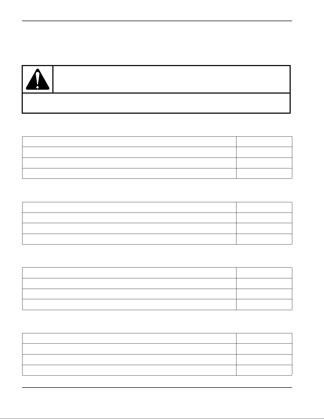
System description
The Powermax30 AIR is a 30 A handheld plasma cutting system that contains its own internal air compressor for
maximum portability and ease of use. With it, you can cut electrically conductive metals – such as mild steel, stainless
steel, or aluminum – of thicknesses up to 10 mm (3/8 inches). You can also pierce thicknesses up to 6 mm (1/4 inch).
The Powermax30 AIR ships in several different configurations, based on region. Typically all configurations include:
1 complete set of consumables (preinstalled on the Air T30 hand torch):
1 electrode
1 swirl ring
1 nozzle
1 retaining cap
1 deflector
1 extra nozzle
1 extra electrode
Carrying strap
Operator Manual
Safety and Compliance Manual
Quick Setup Card
Powermax30 AIR Operator Manual 808840 15

1 – Specifications
420 mm
(16.5 inches)
195 mm
(7.7 inches)
333 mm
(13.1 inches)
295 mm
(11.6 inches)
CSA units ship with a 120 V / 15 A (NEMA 5-15P) adapter and a 240 V / 20 A (NEMA 6-50P) adapter that connect to
the NEMA twist lock-style 240 V / 20 A (NEMA L6-20P) plug wired to the power supply. CE and CCC units ship
without a plug on the power cord. See Power cord considerations on page 27 for more information.
You can order additional consumables and accessories – such as a dust cover and circle cutting guides, for example –
from any Hypertherm distributor. See Parts on page 63 for a list of spare and optional parts.
Power supply dimensions
System weights
The following system weights include the hand torch with 4.6m (15foot) torch lead, a 4.6m (15foot) work lead with
ground clamp, and a 3.0 m (10 foot) power cord:
CSA systems: 13.5 kg (29.8 pounds)
CE and CCC systems: 13.4 kg (29.5 pounds)
16 Powermax30 AIR Operator Manual 808840

1 – Specifications
Hypertherm system ratings
Rated open circuit voltage (U0)256VDC
Output characteristic* Drooping
Rated output current (I
Rated output voltage (U
Rated output voltage (U
U
= 200 VAC – 240 VAC
1
Duty cycle at 40°C, U
)15A to 30A
2
) at U1= 120 VAC 83 VDC
2
) at
2
= 120 VAC
1
20% (I2=30A, U2=83V)
83 VDC
(See data plate on power supply’s rear panel for
more information on duty cycle and for
IEC ratings.)
Duty cycle at 40°C, U
= 200 VAC – 240 VAC
1
35% (I2=30A, U2=83V)
(See data plate on power supply’s rear panel for
more information on duty cycle and for
IEC ratings.)
Operating temperature -10°C to 40°C (14°F to 104°F)
Storage temperature -25°C to 55°C (-13°F to 131°F)
Power factor (120 V – 240 V) 0.99 – 0.97
Idle state power consumption 14W
Power source efficiency at rated maximum
86%
output power**
EMC classification CISPR 11
(CE models only)
Input voltage (U
output (U
2MAX
†
)/ Input current (I1) at rated
1
, I
)
2MAX
120 V, 1-phase, 50/60 Hz, 28.7 A
200 V – 240 V, 1-phase, 50/60 Hz, 16.7 A – 15.0 A
Class A
††
(See Voltage configurations on page 25 for
more information.)
Gas type Air
* Defined as a plot of output voltage versus output current.
** Power source efficiency consumption measured in a laboratory setting with internal compressor disconnected.
† WARNING: This Class A equipment is not intended for use in residential locations where the electrical power is provided by the
public low.voltage supply system. There may be potential difficulties in ensuring electromagnetic compatibility in those locations,
due to conducted as well as radiated disturbances.
‡ This product meets the technical requirements of IEC 61000-3-2 and IEC 61000-3-3 and is not subject to conditional
connection.
Powermax30 AIR Operator Manual 808840 17

1 – Specifications
25 mm
(1.0 inch)
51 mm (2.0 inches)
230 mm (9.0 inches)
45 mm
(1.8 inches)
86 mm
(3.4 inches)
75°
Torch dimensions
Torch weight
Air T30 torch with consumables only: 0.3 kg (0.65 pounds)
Air T30 torch with consumables and 4.6 m (15 foot) lead (with strain relief): 1.0 kg (2.25 pounds)
18 Powermax30 AIR Operator Manual 808840

1 – Specifications
Cutting specifications
240 V
Recommended cut capacity* 8 mm (5/16 inch) at a minimum of 500 mm/minute (20 inches/minute)
10 mm (3/8 inch) at a minimum of 250 mm/minute (10 inches/minute)
Severance cut capacity 16 mm (5/8 inch) at a minimum of 125 mm/minute (5 inches/minute)
* When you operate this system at altitudes higher than 2,200 m (7,500 feet) above sea level, you may experience some reduction
in cutting performance due to the adverse effect that altitude has on air compressors.
120 V
When you operate the system at the maximum recommended output of 20 A, the cut capacities are:
3 mm (10 gauge) at 762 mm/minute (30 inches/minute)
6 mm (1/4 inch) at 355 mm/minute (14 inches/minute)
10 mm (3/8 inch) at 125 mm/minute (5 inches/minute)
Powermax30 AIR Operator Manual 808840 19

1 – Specifications
Direct current (DC)
Alternating current (AC)
Plasma torch cutting
AC input power connection
The terminal for the external
protective (earth) conductor
I Power is ON
O Power is OFF
An inverter-based power
source
Volt/amp curve, “drooping”
characteristic
Power is ON (LED)
Internal air compressor fault
(LED)
Missing or loose consumables
(LED)
Power supply is overheated
(LED)
f
1
f
2
1~
AC
IEC symbols
The following symbols may appear on the power supply data plate, control labels, switches, and LEDs.
Noise levels
This plasma system can make more than the permitted acoustical noise levels as defined by national and local codes.
Always put on correct ear protection when cutting or gouging. Any acoustical noise measurements taken are related to
the specific environment in which the system is used. Refer to Noise can damage hearing in the Safety and Compliance
Manual (80669C).
In addition, you can find an Acoustical Noise Data Sheet for your system at www.hypertherm.com/docs
box, enter data sheet.
20 Powermax30 AIR Operator Manual 808840
. In the search

1 – Specifications
s
Symbols and marks
Your product may have one or more of the following marks on or near the data plate. Because of differences and conflicts
in national regulations, not all marks are applied to every version of a product.
S mark
The S mark indicates that the power supply and torch are suitable for operations carried out in
environments with increased hazard of electrical shock according to IEC 60974-1.
CSA mark
Products with a CSA mark meet the United States and Canadian regulations for product safety.
The products were evaluated, tested, and certified by CSA-International. Alternatively, the product
may have a mark by one of the other Nationally Recognized Testing Laboratories (NRTL)
accredited in both the United States and Canada, such as UL or TÜV.
CE mark
The CE marking signifies the manufacturer’s declaration of conformity to applicable European
directives and standards. Only those versions of products with a CE marking located on or near
the data plate comply with European Directives. Applicable directives may include the European
Low Voltage Directive, the European Electromagnetic Compatibility (EMC) Directive, the Radio
Equipment Directive (RED), and the Restriction of Hazardous Substances (RoHS) Directive.
See the European CE Declaration of Conformity for details.
Eurasian Customs Union (CU) mark
CE versions of products that include an EAC mark of conformity meet the product safety and
EMC requirements for export to Russia, Belarus, and Kazakhstan.
GOST-TR mark
CE versions of products that include a GOST-TR mark of conformity meet the product safety and
EMC requirements for export to the Russian Federation.
RCM mark
CE versions of products with an RCM mark comply with the EMC and safety regulations required
for sale in Australia and New Zealand.
CCC mark
The China Compulsory Certification (CCC) mark indicates that the product has been tested and
found compliant with product safety regulations required for sale in China.
UkrSEPRO mark
The CE versions of products that include a UkrSEPRO mark of conformity meet the product safety
and EMC requirements for export to the Ukraine.
Serbian AAA mark
CE versions of products that include a AAA Serbian mark meet the product safety and
EMC requirements for export to Serbia.
RoHS mark
The RoHS mark indicates that the product meets the requirements of the European Restriction of
Hazardous Substances (RoHS) Directive.
Powermax30 AIR Operator Manual 808840 21

1 – Specifications
United Kingdom Conformity Assessed mark
CE versions of products that include a UKCA mark of conformity meet the product safety, EMC,
RF, and RoHS requirements for export to the UK.
22 Powermax30 AIR Operator Manual 808840

Section 2
Power Supply Setup
Unpack the plasma system
1. Make sure that you received all items on your order in good condition. Contact your distributor if any parts are
damaged or missing. (See System contents on page 24.)
2. Inspect the system for damage that may have occurred during shipment. If you find evidence of damage, see Claims,
below. All communications regarding this equipment must include the model number and the serial number located
on the rear panel of the power supply.
3. Before you set up and operate this system, read the separate Safety and Compliance Manual (80669C) included
with your system for important safety information.
Claims
Claims for damage during shipment – If your unit was damaged during shipment, file a claim with the carrier. You
can contact Hypertherm for a copy of the bill of lading. If you need additional assistance, call the nearest Hypertherm
office listed in the front of this manual.
Claims for defective or missing merchandise – If any component is missing or defective, contact your
Hypertherm distributor. If you need additional assistance, call the nearest Hypertherm office listed in the front of this
manual.
Powermax30 AIR Operator Manual 808840 23

2 – Power Supply Setup
1
2
3
4
5
6
7
8
11
9
10
1
Operator Manual
2
Quick Setup Card
3
Registration card
4
Safety and Compliance Manual
5
Air T30 torch with lead
6
Consumable kit
7
Ground clamp and work lead
8
CE/CCC power cord (no power plug included)
9
CSA power cord with power plug adapters
10
Power supply
11
Carrying strap
System contents
The following illustration shows the components typically included with all system configurations.
The specific components included with the system are subject to change over time.
24 Powermax30 AIR Operator Manual 808840

2 – Power Supply Setup
Position the plasma cutting system
Position the plasma system near an appropriate power receptacle. The system has a 3.0 m (10 foot) power cord.
Allow at least 0.25 m (10 inches) of space around the power supply for proper ventilation.
When positioning the plasma system, be aware that excess moisture from the internal compressor exits through a
hole in the base, underneath the power supply. You may see a small puddle form under the power supply as you
operate the system.
Place the power supply on a stable, level surface before using. The power supply can tip over if set at an angle
greater than 10 degrees.
Do not place the power supply on its side. Doing so can prevent proper air circulation needed to cool internal
components. It can also divert air away from the torch and prevent it from working properly.
Be aware that when you operate this system at altitudes higher than 2,200 m (7,500 feet) above sea level, you may
experience some reduction in cutting performance due to the adverse effect that altitude has on air compressors.
Do not use the system in rain or snow.
WARNING!
CHANCE OF ELECTRIC SHOCK
Never cut under water or submerge the torch in water. Electric shock can cause serious injury.
Prepare the electrical power
The system’s maximum output voltage varies based on the input voltage and the circuit’s amperage.
Additional factors must be considered when you are operating the system at an input power of 120 V, as tripped circuit
breakers can result under some conditions. For more information, see System operation guidelines on page 47 and Basic
troubleshooting on page 56.
Voltage configurations
The system automatically adjusts for proper operation at the current input voltage without requiring you to perform any
switching or rewiring. However, you must make sure that an appropriate set of consumables is properly installed in the
torch and the amperage adjustment knob is set to an appropriate output current. For more information, see
Step 1 – Install the consumables on page 41 and Step 3 – Adjust the output current on page 43.
The following tables show the maximum rated output for typical combinations of input voltage and amperage. The output
setting you need to use depends on the thickness of the metal and is limited by the input power to your system.
Hypertherm does not recommend operating this system on a 120 V / 15 A circuit.
The Hypertherm rated output is:
15 A – 30 A maximum output current
83 VDC maximum rated output voltage
2.5 kW cutting power
Powermax30 AIR Operator Manual 808840 25
2 – Power Supply Setup
Determine the plasma system’s cutting power in watts by multiplying its maximum output amperage by its maximum rated
output voltage:
30 A × 83 VDC = 2,490 W (or 2.5 kW).
CAUTION!
A circuit capable of 120V/20A or 240V/20A is required for proper operation. Protect the circuit
with appropriately sized slow-blow (time-delay) fuses or circuit breakers.
Table1 – 120V/20A
Input voltage 120 V
Input current at rated output (19A×83V=1.6kW) 19.2A
Input current at arc stretch 37.5 A
Voltage tolerance +20% / -15%
Table2 – 120V/30A
Input voltage 120 V
Input current at rated output (30 A × 83 V = 2.5 kW) 28.7 A
Input current at arc stretch 37.5 A
Voltage tolerance +20% / -15%
Table3 – 200V – 240V/16A
Input voltage 200 V – 240 V
Input current at rated output (28A×83V=2.3kW) 15.8A–13.4A
Input current at arc stretch 37.5 A
Voltage tolerance +20% / -15%
Table4 – 200V – 240V/20A
Input voltage 200 V – 240 V
Input current at rated output (30 A × 83 V = 2.5 kW) 16.7 A – 15.0 A
Input current at arc stretch 37.5 A
Voltage tolerance +20% / -15%
26 Powermax30 AIR Operator Manual 808840

2 – Power Supply Setup
Requirements for grounding
Properly ground the system as follows to ensure personal safety and proper operation, and to reduce electromagnetic
interference (EMI):
The system must be grounded through the power cord according to national and local electrical codes.
Single-phase service must be of the three-wire type with a green (CSA) or green/yellow (CE/CCC) wire for the
protective earth ground and must comply with national and local requirements. Do not use a two-wire service.
Refer to the Safety and Compliance Manual (80669C) for more information.
Power cord considerations
This system ships with a CSA or CE, or CCC power cord configuration.
CSA power cords and plugs
CSA configurations include the following plug and adapters.
The power cord is equipped with a NEMA twist
lock-style plug (NEMA L6-20P) appropriate for use on
a 240 V / 20 A circuit with a NEMA twist lock-style
outlet.
To operate the system on a lower amperage circuit,
attach the female end of the 120 V / 15 A
(NEMA 5-15P) plug adapter to the power supply’s
NEMA twist lock-style plug.
Do not set the amperage adjustment knob above
20 A, or you may trip the circuit breaker. See
Step 3 – Adjust the output current on page 43.
To operate the system on a 240 V / 20 A circuit, attach
the female end of the 240 V / 20 A (NEMA 6-50P)
plug to the power supply’s NEMA twist lock-style plug.
Powermax30 AIR Operator Manual 808840 27

2 – Power Supply Setup
1
2
3
4
5
6
1
Cord grip
2
Outer shell
3
To line 1 terminal (brown)
4
220 V (CCC) or 230 V (CE) plug
5
To line 2 terminal (blue)
6
To ground terminal (green/yellow)
CE and CCC power cords
CE and CCC configurations ship without a plug on the power cord. To operate at 220 V (CCC) or 230 V (CE), obtain
the correct plug for your unit and location and have it installed by a licensed electrician.
Install a plug on the power cord
1. Strip back the cord insulation to separate wires 3, 5, and 6.
2. Remove each wire’s insulation to allow good contact with the plug terminals.
3. Make the connections.
4. Reinstall the outer shell and cord grip, and tighten the cord grip’s screws until snug. Do not overtighten.
28 Powermax30 AIR Operator Manual 808840

2 – Power Supply Setup
1
1
Extension cord recommendations
Use an extension cord of an appropriate wire gauge for the cord length and system voltage. Use a cord that meets
national and local codes.
Input voltage Phase
Recommended cord gauge size Length
120 VAC 1 4 mm
240 VAC 1 2 mm
Extension cords can cause the machine to receive less input voltage than the output of
the circuit. This can limit the operation of your system.
Generator recommendations
Generators used with this system should produce 240 VAC.
Engine drive rating
5.5kW 30A Full
4kW 25A Limited
Adjust the cutting current as needed based on the generator rating, age, and condition.
Engine drive output current
1-phase (CSA/CE/CCC)
2
(12 AWG) Up to 16 m (53 feet)
2
(14 AWG) Up to 40.5 m (133 feet)
Performance (arc stretch)
If a fault occurs while using a generator, turn OFF the system and wait approximately
60 seconds before turning it ON again. Turning the power switch quickly to OFF and
ON again (called a “quick reset”) may not clear the fault.
Powermax30 AIR Operator Manual 808840 29

2 – Power Supply Setup
30 Powermax30 AIR Operator Manual 808840

Section 3
1
2
3
4
5
6
1
Handle
2
Deflector
3
Retaining cap
4
Safety catch
5
Trigger (red)
6
Screws (5)
Torch Setup
Introduction
The Powermax30 AIR includes the Air T30 hand torch. This section explains how to set up and operate your torch. To
achieve optimal consumable life and cut quality, follow the instructions in this manual.
Hand torch components
Powermax30 AIR Operator Manual 808840 31

3 – Torch Setup
Consumable life
Consumable life varies based on the following factors:
Thickness of the metal.
Length of the average cut.
Type of cutting (piercing decreases life when compared to edge cutting).
Pierce height (stretching the arc).
Whether you are cutting solid metal or expanded metal. Cutting expanded metal wears out consumables more
quickly. For more information, see Cutting expanded metal on page 43.
Hypertherm does not recommend the use of any other consumables in the Air T30 torch
except for those listed in this section, which are designed specifically for this system. The
use of any other consumables could adversely affect system performance.
Although largely dependent on the factors listed above, as a general rule, the consumables last approximately
1 to 2 hours of actual “arc on” time. See Inspect the consumables on page 55 for information on the signs of wear to
look for in consumables.
If the consumables’ life is shorter than expected or the cut quality is poor, make sure that you are using the correct
consumables and that they are properly installed. (See the following topic, Consumable use.) Under normal conditions,
the nozzle wears out first.
For optimal cutting performance, always replace the nozzle and the electrode together.
See Hand torch operation on page 48 for more information about proper cutting techniques.
32 Powermax30 AIR Operator Manual 808840

3 – Torch Setup
I
O
Consumable use
WARNING!
INSTANT-ON TORCHES
PLASMA ARC CAN CAUSE INJURY AND BURNS
The plasma arc ignites immediately when you pull the torch trigger. Make
sure the power is OFF before changing consumables.
The hand torch ships with a complete set of consumables installed. The consumables are designed for a broad range of
cutting applications.
The amperage output setting you need to use depends on the thickness of the metal you are planning to cut and is limited
by the input power to your system. See Voltage configurations on page 25.
Do not use any other consumables in the Air T30 torch except for those listed in this
section, which are designed specifically for this system. The use of any other consumables
could adversely affect system performance.
Using the cut charts
Use the following cut charts to guide you in selecting the cutting current (amperage) based on the thickness and type of
the metal you need to cut.
The maximum cut speeds listed in the cut charts are the fastest possible speeds to cut metal without regard to cut quality.
Adjust the cutting speed for your application to obtain the desired cut quality.
Powermax30 AIR Operator Manual 808840 33

3 – Torch Setup
54321 6
1
To rc h
2
Electrode
3
Swirl ring
4
Nozzle
5
Retaining cap
6
Deflector
Consumable set
A complete set of consumables includes:
Electrode
Swirl ring
Nozzle
Retaining cap
Deflector
Hypertherm does not recommend operating this system on a 120 V / 15 A circuit.
The following consumables are designed specifically for use with the Powermax30 AIR power supply and Air T30 hand torch. They cannot be used with
any other Powermax system or torch.
34 Powermax30 AIR Operator Manual 808840

Metric
3 – Torch Setup
240V/30A cutting
Material thickness (mm) Material Arc current (A)
1
2 5,145
3 2,545
4 1,450
5 1,155
7* 570
Mild steel 30
9* 400
11* 280
13* 215
16* 125
1
2 3,290
3 1,970
4 1,260
5 980
Stainless steel 30
7* 535
9* 310
11* 215
13* 170
1
2 6,630
3 3,585
4 2,370
5 1,770
Aluminum 30
7* 575
9* 435
11* 245
13* 135
Maximum cut speed
(mm/minute)
10,160
10,160
10,160
†
†
†
* To cut material thicker than 6 mm (1/4 inch) at 240 V, start the torch at the edge of the workpiece.
† Maximum cut speed is limited by the test table’s maximum speed (10,160 mm/minute or 400 inches/minute).
Powermax30 AIR Operator Manual 808840 35

3 – Torch Setup
English
Material thickness
(gauge/inches)
Material Arc current (A)
Maximum cut speed
18 gauge
14 gauge 214
12 gauge 130
10 g auge 64
1/4 30
Mild steel 30
5/16* 22
3/8* 13
1/2* 9
5/8* 5
18 gauge
14 gauge 135
10 g auge 56
1/4 24
Stainless steel 30
3/8* 10
1/2* 7
1/32
1/16 306
1/8 111
1/4 38
Aluminum 30
3/8* 13
1/2* 6
(inches/minute)
395
370
†
400
* To cut material thicker than 6 mm (1/4 inch) at 240 V, start the torch at the edge of the workpiece.
† Maximum cut speed is limited by the test table’s maximum speed (10,160 mm/minute or 400 inches/minute).
36 Powermax30 AIR Operator Manual 808840

Metric
3 – Torch Setup
120 V / 20 A cutting
Material thickness (mm) Material Arc current (A)
1
2 2,420
3 1,245
4* 680
6* 400
8* 235
10* 90
1
2 2,140
3 1,270
4* 965
5* 660
7* 150
1
2 3,610
3 1,720
4* 1,030
5* 740
7* 165
Mild steel 20
Stainless steel 20
Aluminum 20
Maximum cut speed
(mm/minute)
6,540
3,295
5,500
* To cut material thicker than 3 mm (10 gauge) at 120 V, start the torch at the edge of the workpiece.
Powermax30 AIR Operator Manual 808840 37

3 – Torch Setup
English
Material thickness
(gauge/inches)
18 gauge
14 gauge 10 0
10 g auge 30
1/4* 14
3/8* 5
18 gauge
14 gauge 89
12 gauge 54
1/4* 10
1/32
1/16 170
1/8 49
1/4* 14
* To cut material thicker than 3 mm (10 gauge) at 120 V, start the torch at the edge of the workpiece.
Material Arc current (A)
Mild steel 20
Stainless steel 20
Aluminum 20
Maximum cut speed
(inches/minute)
220
120
231
38 Powermax30 AIR Operator Manual 808840

Controls and indicators
O
Familiarize yourself with the controls and LED indicators on the system before you begin cutting.
Rear controls
Section 4
Operation
ON (I) / OFF (O) power switch
Activates the system and its control circuits.
Powermax30 AIR Operator Manual 808840 39

4 – Operation
AC
Front panel controls and indicator LED symbols
Power ON LED (green) – When illuminated, this LED indicates that the power switch has been set to ON (I)
and that the safety interlocks are satisfied.
Internal compressor LED (yellow) – When illuminated, this LED indicates a possible issue with the internal
air compressor.
Torch cap LED (yellow) – When illuminated, this LED indicates that the consumables are loose, improperly
installed, or missing.
Temperature LED (yellow) – When illuminated, this LED indicates that the system’s temperature is outside
the acceptable operating range.
Some fault conditions cause multiple LEDs to illuminate or blink at the same time. For
information on what these fault conditions are and how to clear them, see Basic
troubleshooting on page 56.
Amperage adjustment knob – Use this knob to set the output current
between 15 A and 30 A.
40 Powermax30 AIR Operator Manual 808840

Operate the plasma system
I
O
Tighten only to finger tight.
1
2
3
4
5
1
234
5
The following topics explain how to begin cutting with the plasma system.
Step 1 – Install the consumables
WARNING!
INSTANT-ON TORCHES
PLASMA ARC CAN CAUSE INJURY AND BURNS
The plasma arc ignites immediately when you pull the torch trigger. Make
sure the power is OFF (O) before changing consumables.
Before operating the plasma system
and hand torch, first make sure:
1. The power switch on the power
supply is in the OFF (O) position.
4–Operation
2. A complete set of consumables is
installed on the hand torch
as shown:
Electrode
Swirl ring
Nozzle
Retaining cap
Deflector*
* Install the deflector by snapping it
securely into place on the retaining cap.
Do not apply grease or
other lubricants to the
O-rings on the electrode
and swirl ring.
These consumables are designed specifically for the Powermax30 AIR power supply and
Air T30 hand torch. They cannot be used with any other Powermax system or torch.
Powermax30 AIR Operator Manual 808840 41
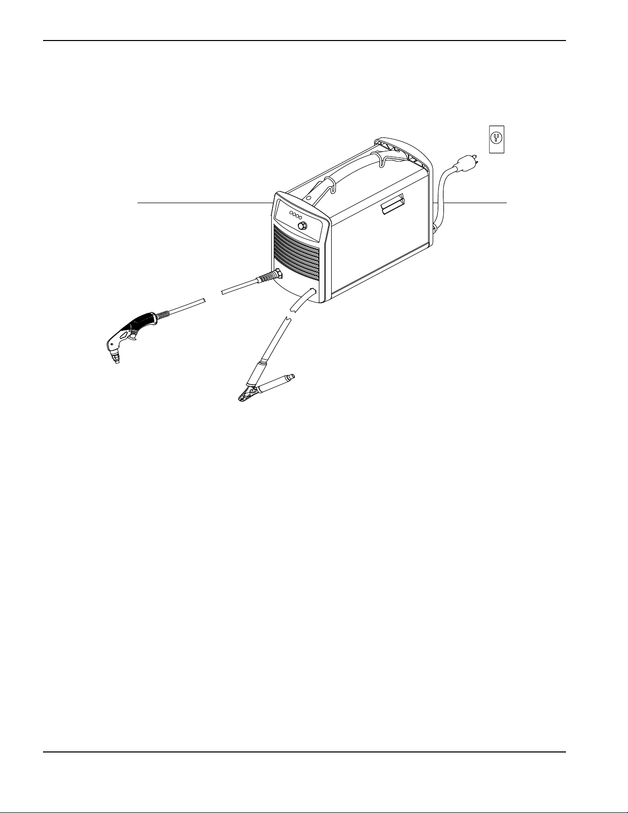
4 – Operation
Step 2 – Connect the electrical power
Plug in the power cord.
See also
For information on connecting the proper plug to the power cord, see Power cord considerations on page 27.
To understand what cutting capacity to expect based on input voltage, see Consumable use on page 33.
For information on electrical requirements for this system, see Power Supply Setup on page 23.
42 Powermax30 AIR Operator Manual 808840

4–Operation
Blue shading
Step 3 – Adjust the output current
The power ON LED illuminates when the system is powered ON and ready to operate.
If any of the other LEDs illuminate or blink, do not try to cut – a fault has occurred. Refer to Basic troubleshooting on
page 56 for a list of troubleshooting steps to follow.
When the system is ready to cut, turn the amperage knob to the desired output current based on the input voltage and
circuit size.
Operating the system on a 120 V / 20 A circuit
Set the amperage below 20 A, as indicated by the
blue shading around the knob (the thick inner ring).
Make sure nothing else is drawing power from the
circuit.
Hypertherm does not recommend operating this
system on a 120 V / 15 A circuit.
Operating the system on a 240 V / 20 A circuit
Set the amperage between 15 – 30 A.
Decrease output current for lower-rated power plugs
If you are operating the system using a lower-rated power
plug or service, turn down the output current to avoid
tripping the circuit breaker.
For example, to operate the system on a 230 V / 16 A
circuit, set the amperage below 28 A.
See Voltage configurations on page 25 for more information.
Cutting expanded metal
Use the consumables that come with the torch to cut expanded metal. (Expanded metal has a slotted or mesh pattern.)
The system does not require a dedicated mode for cutting expanded metal.
Cutting expanded metal wears out consumables more quickly because it requires a continuous pilot arc. A pilot arc
occurs when the torch is fired but the plasma arc is not in contact with the workpiece.
For best results, operate on a higher rated circuit (240 V / 20 A).
Powermax30 AIR Operator Manual 808840 43
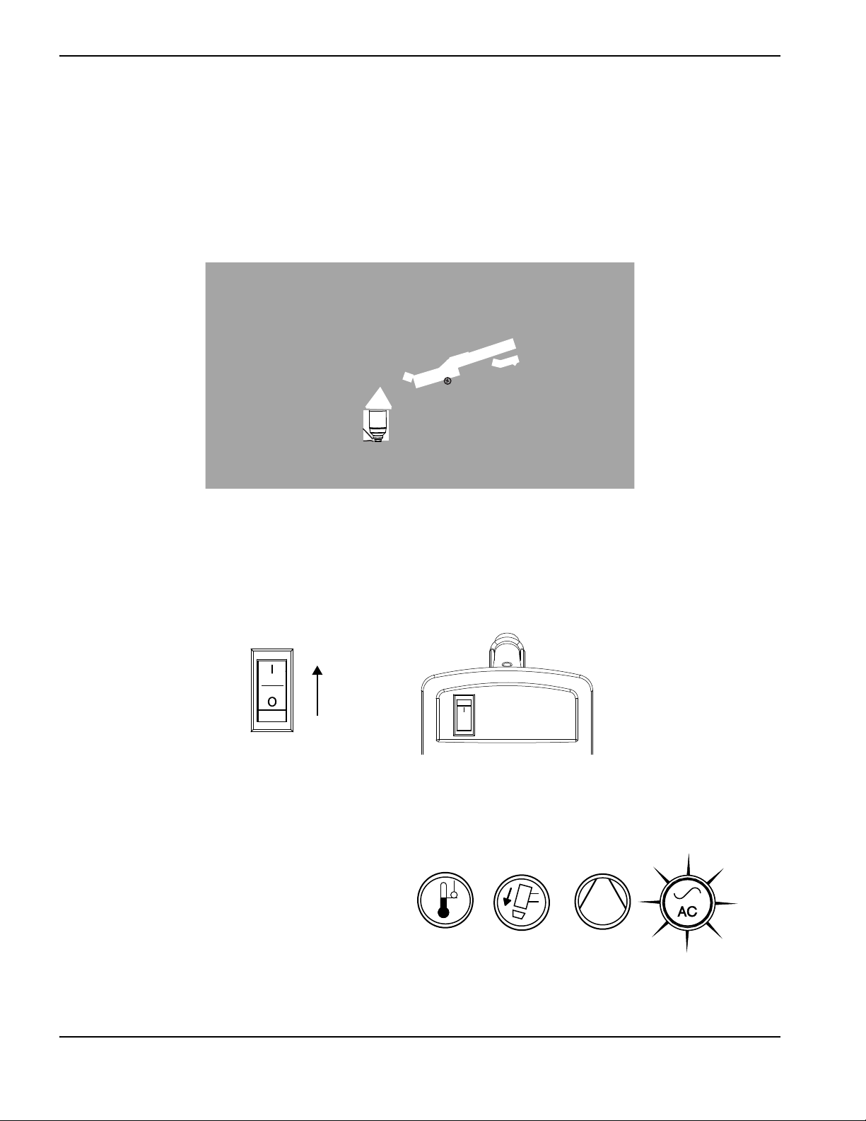
4 – Operation
O
Step 4 – Attach the ground clamp
Attach the ground clamp to the workpiece.
Make sure the ground clamp and the workpiece make good metal-to-metal contact.
Attach the ground clamp as close as possible to the area being cut to reduce exposure to electric and magnetic
fields (EMF) and to achieve the best possible cut quality.
Do not attach the ground clamp to the portion of the workpiece that you are cutting away.
Step 5 – Power ON the system
Set the ON/OFF switch to the ON (I) position.
Step 6 – Check the indicator LEDs
Make sure the green power ON LED on the front
of the power supply is illuminated and that none of
the other LEDs are illuminated or blinking.
If the temperature, torch cap sensor, or internal
compressor LEDs illuminate or blink, or if the
power ON LED blinks, this indicates a fault.
Correct the fault condition before continuing. See
Basic troubleshooting on page 56 for more
information.
44 Powermax30 AIR Operator Manual 808840

4–Operation
Step 7 – Make sure the system is ready, and start cutting
When the power ON LED illuminates, none of the other LEDs illuminate or blink, and the amperage knob is set, the
system is ready for use.
What to expect during and after cutting
Water at the torch nozzle
A small amount of moisture at the torch nozzle is normal for this system, particularly in very humid environments. It
should not prevent the torch from firing or degrade cut quality or performance.
Postflow
After you complete a cut and release the torch trigger, air continues to flow from the torch in order to cool the
consumables. This is referred to as postflow.
The length of postflow depends on how long the torch fired a sustained arc:
Length of time arc was sustained Length of postflow
0–5seconds 5seconds
> 5 – 21 seconds 10 seconds
> 21 – 135 seconds 15 seconds
> 135 seconds 20 seconds
Internal compressor and fan activity
The internal compressor runs while you are cutting, and it continues to run during postflow.
The fan inside the power supply runs for 7 minutes after postflow. It also runs intermittently during cutting.
Water under the power supply
When cutting, you may see a small puddle form underneath the power supply because the system automatically
purges excess moisture from the internal compressor. It expels this water through a hole in the bottom of the power
supply.
Powermax30 AIR Operator Manual 808840 45

4 – Operation
Understand duty-cycle limitations
The duty cycle is the percentage of time out of 10 minutes that a plasma arc can remain on when operating at an ambient
temperature of 40°C (104°F).
35% duty cycle at 240 V / 30 A: With input power of 240 V and the output current set to 30 A, the arc can remain
on for 3.5 minutes out of 10 minutes without causing the unit to overheat.
20% duty cycle at 120 V / 30 A*: With input power of 120 V and the output current set to 30 A, the arc can
remain on for 2.0 minutes out of 10 minutes without causing the unit to overheat.
* Although the duty cycle is rated for 30 A output, the recommended output current for 120 V circuits is 20 A or less. Operating the
system at 30 A on 120 V input can result in frequent tripped circuit breakers.
When you exceed the duty cycle and the system overheats, one of the following conditions occurs:
The temperature LED illuminates, the arc shuts off, and the cooling fan continues to run. To resume cutting, wait for
the temperature LED to extinguish.
The internal compressor LED and the temperature LED both illuminate. Allow the power supply to cool for 4 minutes
before using it again. If the problem persists, see Internal compressor LED faults on page 58 for more
troubleshooting tips.
When either condition occurs, leave the system on to allow the fan to cool the power
supply. The fan runs for 7 minutes after postflow.
Stretching the arc for prolonged periods while cutting can reduce the duty cycle. Stretching the arc requires the power
supply to generate a higher voltage output, which can cause it to run hotter and overheat more quickly.
46 Powermax30 AIR Operator Manual 808840

4–Operation
System operation guidelines
To achieve the highest level of performance:
Operate the system at an input power of 240 VAC whenever possible.
Do not operate the system on a 120 V / 15 A circuit.
Avoid using an extension cord whenever possible.
If you must use an extension cord, use a heavy conductor cord of the shortest possible
length. See Extension cord recommendations on page 29.
If you are operating your system on a 120 V / 20 A circuit, do not set the amperage higher than 20 A. See Voltage
configurations on page 25.
For best results when operating your system on a 120 V / 20 A circuit:
Do not connect anything else that will draw power from the same circuit.
Be aware that extension cords can reduce the voltage to the machine from what is output by the circuit. This
reduction in power can impair cutting performance and increase the probability of tripping the circuit breaker.
Cutting a thicker workpiece requires a higher amperage setting. It is preferable to operate on a higher rated circuit
(240 V / 30 A) when cutting thicker metal. See Voltage configurations on page 25.
Additional techniques to reduce the frequency of tripped circuit breakers include:
Turn down the amperage adjustment knob.
Avoid stretching the arc. Instead, drag the torch on the workpiece as explained in Edge start on a workpiece on
page 50.
When you operate the system at altitudes higher than 2,200 m (7,500 feet) above sea level, you may experience
some reduction in cutting performance due to the adverse effect that altitude has on the internal air compressor.
Powermax30 AIR Operator Manual 808840 47

4 – Operation
1
2
3
Hand torch operation
WARNING!
INSTANT-ON TORCHES
PLASMA ARC CAN CAUSE INJURY AND BURNS
Plasma arc ignites immediately when you pull the torch trigger. The plasma arc cuts quickly through
gloves and skin.
Keep hands, clothes, and objects away from the torch tip.
Do not hold the workpiece, and keep your hands clear of the cutting path.
Never point the torch toward yourself or others.
WARNING!
SPARKS AND HOT METAL
CAN INJURE EYES AND BURN SKIN
Always wear proper protective equipment including gloves and eye protection, and point the torch
away from yourself and others. Sparks and hot molten metal spray out from the nozzle.
Safety catch operation
The torch is equipped with a safety catch to prevent accidental firings. When you are ready to cut with the torch, flip the
safety catch forward (toward the torch head) and pull the red torch trigger.
48 Powermax30 AIR Operator Manual 808840

4–Operation
Hand torch cutting guidelines
Drag the torch tip lightly on the workpiece to maintain a steady cut speed.
With drag-cutting, it is normal to experience the torch sticking slightly to the workpiece.
While cutting, make sure that sparks exit from the bottom of the workpiece. The sparks should lag slightly behind the
torch as you cut (15°–30° angle from vertical).
If sparks spray up, you are not cutting all the way through the workpiece. Move the torch more slowly, or, if possible,
increase the output current.
Hold the torch nozzle perpendicular to the workpiece so that the nozzle is at a 90° angle to the cutting surface, and
watch the arc as it cuts along the line.
Pulling the torch toward you along the cut is easier than pushing it or moving from side-to-side.
For straight-line cuts, use a straight edge as a guide. To cut circles, use a template or a radius cutter attachment (a
circle cutting guide). See Accessory parts on page 67 for the Hypertherm plasma cutting guide part numbers for
cutting circles and making bevel cuts.
If you fire the torch unnecessarily, you shorten the life of the nozzle and electrode.
Recommendations for cutting at 120 V
Do not operate the system on a 15 A circuit.
Do not use an extension cord.
Make sure nothing else is drawing power from the circuit.
Turn down the current adjustment knob to avoid tripping the breaker.
Powermax30 AIR Operator Manual 808840 49

4 – Operation
Edge start on a workpiece
When cutting material up to 10 mm (3/8 inch) thick, start the torch at the edge of the workpiece to prolong consumable
life.
1. With the ground clamp attached to the workpiece,
hold the torch perpendicular (90°) to the workpiece
and on the edge.
2. Pull the torch trigger to start the arc. You may need
to pause at the edge until the arc has cut completely
through the workpiece.
3. Drag the torch lightly across the workpiece to
proceed with the cut. Maintain a steady, even pace.
50 Powermax30 AIR Operator Manual 808840

4–Operation
30° – 45° for rolling pierce
Pierce a workpiece
When cutting material up to 6 mm (1/4 inch) thick, use piercing to cut an interior feature. Piercing shortens the life of the
deflector and the nozzle.
The type of pierce to perform depends on the thickness of the metal:
Straight pierce – For cutting mild or stainless steel that is thinner than 3 mm (10 gauge).
Rolling pierce – For cutting mild or stainless steel that is 3 mm (10 gauge) or thicker.
1. Attach the ground clamp to the workpiece.
2. Straight pierce: Hold the torch perpendicular (90°)
to the workpiece with the torch tip just above the
workpiece.
Rolling pierce: Hold the torch at an approximate
30° – 45° angle to the workpiece with the torch tip
within 1.5 mm (1/16 inch) of it before firing the
torch.
3. Straight pierce: Pull the torch trigger to start the
arc.
Rolling pierce: Pull the torch trigger to start the arc
while still at an angle to the workpiece, then rotate
the torch to the perpendicular (90°) position.
4. Hold the torch in place while continuing to pull the
trigger. When sparks exit from the bottom of the
workpiece, the arc has pierced the metal.
5. When the pierce is complete, drag the torch lightly
along the workpiece to proceed with the cut.
Powermax30 AIR Operator Manual 808840 51

4 – Operation
Common hand-cutting faults
For more information on faults, see Basic troubleshooting on page 56.
The torch sputters and hisses, but does not produce an arc. The cause can be:
Overtightened consumables
The torch does not cut completely through the workpiece. The causes can be:
Cut speed is too fast
Worn consumables
Metal being cut is too thick for the selected amperage
Installation of the wrong consumables
Poor electrical contact between the ground clamp and the workpiece
Cut quality is poor. The causes can be:
Metal being cut is too thick for the selected amperage
Installation of the wrong consumables
Cut speed is too fast or too slow
Worn or damaged consumables
The arc sputters and consumables life is shorter than expected. The causes can be:
Incorrect installation of the consumables
Installation of the wrong consumables
Moisture in the consumables or in the air supply within the system
Minimizing dross
Dross is the molten metal that solidifies on the workpiece. Some amount of dross is always present when cutting with air
plasma. However, you can control the amount and type of dross by adjusting your system correctly for your application.
Low-speed dross forms when the torch’s cutting speed is too slow and the arc shoots ahead. It forms as a heavy, bubbly
deposit at the bottom of the cut and is usually easy to remove. Increase your speed to reduce this type of dross.
High-speed dross forms when the cutting speed is too fast and the arc lags behind. It forms as a thin, linear bead of solid
metal attached very close to the cut. It forms to the bottom of the cut and is often more difficult to remove. Decrease your
speed to reduce this type of dross.
Dross is more likely to form on warm or hot metal than on cool metal. For example, the
first cut in a series of cuts is likely to produce the least dross. As the workpiece heats up,
more dross may form on subsequent cuts.
Worn or damaged consumables may produce intermittent dross.
52 Powermax30 AIR Operator Manual 808840

Perform routine maintenance
Disconnect electrical power before performing any maintenance that
involves removing the cover from the power supply or the consumables from
the torch.
All work requiring removal of the power supply cover must be performed by
a qualified technician.
See the Safety and Compliance Manual (80669C) for more safety
precautions.
Section 5
Maintenance and Troubleshooting
WARNING!
ELECTRIC SHOCK CAN KILL
Powermax30 AIR Operator Manual 808840 53

5 – Maintenance and Troubleshooting
Every use:
Check the indicator lights and correct any fault
conditions.
Every 3 months:
Replace any damaged labels. Inspect the trigger for damage. Inspect the torch body
Inspect the power cord and plug.
Replace if damaged.
Inspect the consumables for proper installation and
wear.
for cracks and exposed wires. Replace any damaged
parts.
Inspect the torch lead. Replace if damaged.
54 Powermax30 AIR Operator Manual 808840

Inspect the consumables
Good
Worn
O-ring
Maximum 1 mm (0.04
inches)
O-ring
Part Inspect Action
5 – Maintenance and Troubleshooting
Deflector*
Nozzle
Electrode
The center hole for roundness.
The rounded edges of the center hole
for damage or noticeable wear.
The gap between the nozzle and the
deflector for accumulated debris.
Replace the deflector if the hole is no
longer round or if it is worn or
damaged.
Remove the deflector and clean any
material away.
The center hole for roundness. Replace if the center hole is not round.
Replace the nozzle and the electrode
together.
The center surface for wear and verify
the pit depth.
Replace if the surface is severely worn
or the pit depth is greater than 1 mm
(0.04 inches) deep. Replace the nozzle
and the electrode together.
Do not apply grease or other lubricants
to the O-ring on the electrode.
The internal surface for damage or
wear and the gas holes for blockages.
Replace if the surface is damaged or
worn or any of the gas holes are
blocked.
Do not apply grease or other lubricants
to the O-ring on the swirl ring.
Swirl ring
The length of the swirl ring. If the length of the swirl ring is less than
21 mm (0.83 inches), replace it.
The surface for damage, wear, or a lack
of lubrication.
If the torch O-ring is dry, apply a thin
film of silicone lubricant on the O-ring
and the threads. The O-ring should
look shiny, but there should not be any
excess or built-up lubricant.
Torch O-ring
If the O-ring is cracked or worn,
replace it.
* Initial Air T30 torches used deflectors made from anodized aluminum. These deflectors are now made from copper. Examine
aluminum deflectors for signs of deformation. If necessary, replace them with the newer copper deflector.
Powermax30 AIR Operator Manual 808840 55

5 – Maintenance and Troubleshooting
AC
AC
AC
Basic troubleshooting
The following sections provide an overview of the most common problems that may arise when using this system and
explains how to solve them.
If you are unable to fix the problem by following this basic troubleshooting guide or if you need further assistance:
1. Call your Hypertherm distributor or authorized Hypertherm repair facility.
2. Call the nearest Hypertherm office listed in the front of this manual.
Power LED faults
The ON/OFF power switch is set to ON (I),
but the power ON LED does not illuminate.
Make sure the power cord is plugged into the receptacle.
Make sure the power is on at the main power panel or at the disconnect-power switch box.
Make sure the line voltage is not too low (more than 15% below the rated voltage).
The power ON LED blinks.
Have an electrical technician check the incoming power. The input line voltage is either too high or
too low (a variance greater than ±15% of the rated voltage). See Hypertherm system ratings on
page 17 and Prepare the electrical power on page 25.
All four LEDs blink when the system is powered ON.
A qualified service technician must service the system. Contact your distributor or use the
information in the front of this manual to contact Hypertherm Technical Service.
56 Powermax30 AIR Operator Manual 808840

5 – Maintenance and Troubleshooting
Temperature LED faults
The temperature LED illuminates while the machine is powered ON.
The system overheated. Leave the system on to allow the fan to cool the power supply.
If the system’s internal temperature approaches -30°C (-22°F), the temperature LED may
illuminate. Move the system to a warmer location.
The temperature LED blinks while the machine is powered ON.
Leave the system on to allow the fan to cool the power supply. The temperature LED blinks when
the system continuously draws too much input current for too long. Try the following to prevent this
condition:
Turn down the cutting current. See Step 3 – Adjust the output current on page 43.
Operate the system on a 240 VAC input circuit whenever possible.
Avoid stretching the arc. Drag the torch on the workpiece. See Edge start on a
workpiece on page 50.
Operate the system without using an extension cord. If you must use an extension
cord, use a heavy conductor cord of the shortest possible length. See Extension cord
recommendations on page 29.
Make sure nothing else is drawing power on the same circuit.
Powermax30 AIR Operator Manual 808840 57

5 – Maintenance and Troubleshooting
Internal compressor LED faults
The internal compressor LED and the temperature LED illuminate while
the machine is powered ON.
The internal compressor may have overheated. Allow the power supply to cool for 4 minutes before
using it again. (See Understand duty-cycle limitations on page 46.)
When the internal compressor overheats, the compressor and temperature LEDs remain
illuminated for 4 minutes.
The system does not prevent you from firing the torch before the 4 minutes
elapses. However, if you begin cutting before the compressor has time to
fully cool down, the same fault is likely to occur again.
Place the power supply right-side up on a level surface. Laying the power supply on its side can
prevent proper air circulation needed to cool internal components. It can also cause the air filter to
divert air away from the torch.
Inspect and replace the consumables if they are worn or damaged. Always replace the nozzle and
electrode together. See Inspect the consumables on page 55.
Was the system stored in temperatures below freezing? If so, ice might have formed inside the
power supply. Move the power supply to a warmer location to allow the ice to melt.
If none of these troubleshooting steps resolves the issue, a qualified service technician must
service the system. Contact your distributor or use the information in the front of this manual to
contact Hypertherm Technical Service.
The internal compressor LED and the temperature LED blink alternately
when the machine is powered ON.
Release the trigger and restart the power supply. The system automatically disables itself when the
power supply is turned on while the torch trigger is pulled.
58 Powermax30 AIR Operator Manual 808840

5 – Maintenance and Troubleshooting
AC
Torch LED faults
The torch cap LED illuminates or blinks while the machine is
powered ON.
Inspect the torch lead. If it is twisted or kinked, straighten it out and try to fire the torch again.
Turn OFF ( O) the power supply. Make sure the consumables are properly installed and tightened.
See Step 1 – Install the consumables on page 41.
If the consumables became loose or were removed while the power supply was ON, turn OFF (O)
the power supply, correct the problem, and then turn ON (I) the power supply to clear the fault.
If the consumables appear to be installed correctly, the torch may be damaged. Contact your
Hypertherm distributor or authorized repair facility.
The internal compressor, temperature, and power ON
LEDs blink, and the torch cap LED illuminates.
Install new consumables in the torch (they may be corroded or approaching end of life).
If you continue to see this error, contact your Hypertherm distributor or authorized repair facility.
Powermax30 AIR Operator Manual 808840 59

5 – Maintenance and Troubleshooting
Common cutting issues
Problem Solution
The circuit breaker trips
while you are cutting.
The cut quality is poor. • Make sure the torch is being used correctly. See Hand torch operation on
• Turn down the cutting current. See Step 3 – Adjust the output current on
page 43.
• Operate the system on a 240 VAC input circuit whenever possible.
• Avoid stretching the arc. Drag the torch on the workpiece. See Edge start
on a workpiece on page 50.
• Operate the system without using an extension cord. If you must use an
extension cord, use a heavy conductor cord of the shortest possible
length. See Extension cord recommendations on page 29.
• Make sure nothing else is drawing power on the same circuit.
page 48.
• Make sure the correct consumables are installed. See Consumable use
on page 33.
• Inspect the consumables and replace as necessary. See Inspect the
consumables on page 55.
• Loosen the consumables about 1/8th of a turn and try again.
• Make sure the work lead connection is secure and there is no damage to
the work lead.
• Operate the system without using an extension cord. If you must use an
extension cord, use a heavy conductor cord of the shortest possible
length. See Extension cord recommendations on page 29.
The torch does not cut
completely through the
workpiece.
The arc does not transfer
to the workpiece.
• Make sure the torch is being used correctly. See Hand torch operation on
page 48.
• Inspect the consumables and replace as necessary. See Inspect the
consumables on page 55.
• Clean the area where the ground clamp contacts the workpiece to ensure
a good metal-to-metal contact.
• Inspect the ground clamp for damage and repair it if necessary.
• Move the torch closer to the workpiece and fire the torch again. See Hand
torch operation on page 48.
60 Powermax30 AIR Operator Manual 808840

Problem Solution
5 – Maintenance and Troubleshooting
A small amount of moisture
exits the torch nozzle.
The arc blows out but
re-ignites when the torch
trigger is pulled again, or
the arc sputters and
hisses.
• A small amount of moisture at the torch nozzle is normal for this
system, particularly in very humid environments. It should not prevent the
torch from firing or degrade cut quality or performance.
• If excess moisture exiting the torch does interfere with starting the torch or
with cutting performance, contact your Hypertherm distributor or
authorized repair facility.
• First, inspect the consumables for signs of excess moisture. A small
amount of moisture at the torch nozzle is normal for this system
and should not prevent the torch from firing. If excess moisture is
present, fire the torch approximately 5 times in succession.
• If firing the torch does not clear out the excess moisture, and the moisture
exiting the torch does interfere with starting the torch or with cutting
performance, contact your Hypertherm distributor or authorized repair
facility.
• If the problem persists and excess moisture is not an issue, inspect and
replace the consumable parts if they are worn or damaged. See Inspect
the consumables on page 55.
Powermax30 AIR Operator Manual 808840 61

5 – Maintenance and Troubleshooting
62 Powermax30 AIR Operator Manual 808840

Section 6
Parts
Use the part numbers and kit numbers in this section to order consumables, accessories, and external replacement parts
for your power supply and hand torch.
For instructions on installing the consumables in the hand torch, see Step 1 – Install the
consumables on page 41.
This system contains no customer serviceable parts inside the power supply or inside the hand torch. For assistance with
repairing or replacing internal components:
1. Call your Hypertherm distributor or authorized Hypertherm repair facility.
2. Call the nearest Hypertherm office listed in the front of this manual.
Powermax30 AIR Operator Manual 808840 63

6 – Parts
1
2
3
Power supply parts
Exterior, front
Item Kit number Description
1 228267 Kit: Power supply handle (includes screws and shoulder strap clips)
2 428226 Kit: Current adjustment knob
3 228561 Kit: Ground clamp
64 Powermax30 AIR Operator Manual 808840

Exterior, rear
1
2
NEMA 6-50P
NEMA 5-15P
NEMA L6-20P
6 – Parts
Item Kit number Description
1 229133 CSA power cord extension: 240 V / 20 A plug adapter
2 229132 CSA power cord extension: 120 V / 15 A plug adapter
428392 Kit: Replacement bumpers (rubber “feet”) for bottom of power supply (4)
(not shown)
Powermax30 AIR Operator Manual 808840 65

6 – Parts
420133420132 420134 420135
Electrode Swirl ring Nozzle Retaining cap
428179
Torch O-ring Deflector
420399
428350
Hand torch consumables
To order consumables for your Air T30 torch, use the following part numbers.
You can order individual packages of nozzles and electrodes, or you can order them combined as a kit:
Use 420134 to order a package of 5 nozzles.
Use 420132 to order a package of 5 electrodes.
Use 428350 to order a kit of 2 nozzles and 2 electrodes.
These consumables are designed specifically for use with the Powermax30 AIR power
supply and Air T30 hand torch. They cannot be used with any other Powermax system or
torch.
Individual consumables
Kit: electrode (2) + nozzle (2)
66 Powermax30 AIR Operator Manual 808840

Accessory parts
Part number Description
127102 Basic plasma (circle) cutting guide
027668 Deluxe plasma (circle) cutting guide
127144 Dust cover
024877 Leather torch lead cover, black with Hypertherm logo, 7.6 m (25 feet)
127217 Shoulder strap
127169 Leather cutting gloves
127416 Protective glasses, shade 5 lens
6 – Parts
Powermax30 AIR Operator Manual 808840 67

6 – Parts
210347 Rev. A
420135 420134 420133 420132420399
428350
Power supply labels
Kit number Description
428408 Kit: Powermax30 AIR labels, CSA
428410 Kit: Powermax30 AIR labels, CSA, Built in America
428409 Kit: Powermax30 AIR labels, CE/CCC
The label kits include:
Consumables label
Appropriate warning labels
Front and side decals
The following illustrations show the consumables label and warning labels.
Consumables label
The consumables label is affixed to the power supply’s rear panel. It shows the correct consumables to use with this
system and torch and how to install them.
68 Powermax30 AIR Operator Manual 808840

6 – Parts
WARNING: This product can expose you to chemicals including
lead and lead compounds, which are known to the State of
California to cause cancer and birth defects or other reproductive
harm. For more information go to www.p65warnings.ca.gov.
AVERTISSEMENT : Ce produit peut vous exposer à des produits chimiques, dont
le plomb et des composés de plomb, reconnus par l’État de la Californie comme cause
de cancer et d’anomalie congénitale ou d’autres anomalies de l’appareil reproducteur.
Pour obtenir de plus amples renseignements, consultez le www.p65warnings.ca.gov.
Read and follow these instructions, employer safety
practices, and material safety data sheets. Refer to
ANS Z49.1, “Safety in Welding, Cutting and Allied
Processes” from American Welding Society
(http://www.aws.org) and OSHA Safety and Health
Standards, 29 CFR 1910 (http://www.osha.gov).
WARNING
1. Cutting sparks can cause explosion or fire.
1.1 Do not cut near flammables.
1.2 Have a fire extinguisher nearby and ready to use.
1.3 Do not use a drum or other closed container as a cutting
table.
2. Plasma arc can injure and burn; point the nozzle
away from yourself. Arc starts instantly when
triggered.
2.1 Turn off power before disassembling torch.
2.2 Do not grip the workpiece near the cutting path.
2.3 Wear complete body protection.
3. Hazardous voltage. Risk of electric shock or burn.
3.1 Wear insulating gloves. Replace gloves when wet or
damaged.
3.2 Protect from shock by insulating yourself from work and
ground.
3.3 Disconnect power before servicing. Do not touch live parts.
4. Plasma fumes can be hazardous.
4.1 Do not inhale fumes.
4.2 Use forced ventilation or local exhaust to remove the fumes.
4.3 Do not operate in closed spaces. Remove fumes with
ventilation.
6. Become trained. Only qualified personnel should
operate this equipment. Use torches specified in the manual.
Keep non-qualified personnel and children away.
5. Arc rays can burn eyes and injure skin.
5.1 Wear correct and appropriate protective equipment to
protect head, eyes, ears, hands, and body. Button shirt
collar. Protect ears from noise. Use welding helmet with
the correct shade of filter.
7. Do not remove, destroy, or cover this label.
Replace if it is missing, damaged, or worn.
Plasma cutting can be injurious to operator and persons in the
work area. Consult manual before operating. Failure to follow
all these safety instructions can result in death.
AVERTISSEMENT
Le coupage plasma peut être préjudiciable pour l’opérateur
et les personnes qui se trouvent sur les lieux de travail.
Consulter le manuel avant de faire fonctionner. Le non respect
des ces instructions de sécurité peut entraîner la mort.
1. Les étincelles de coupage peuvent provoquer
une explosion ou un incendie.
1.1 Ne pas couper près des matières inflammables.
1.2 Un extincteur doit être à proximité et prêt à être utilisé.
1.3 Ne pas utiliser un fût ou un autre contenant fermé comme
table de coupage.
2. L’arc plasma peut blesser et brûler; éloigner
la buse de soi. Il s’allume instantanément
quand on l’amorce.
2.1 Couper l’alimentation avant de démonter la torche.
2.2 Ne pas saisir la pièce à couper de la trajectoire de coupage.
2.3 Se protéger entièrement le corps.
3. Tension dangereuse. Risque de choc électrique
ou de brûlure.
3.1 Porter des gants isolants. Remplacer les gants quand ils sont
humides ou endommagés.
3.2 Se protéger contre les chocs en s’isolant de la pièce et de
la terre.
3.3 Couper l’alimentation avant l’entretien. Ne pas toucher
les pièces sous tension.
4. Les fumées plasma peuvent être dangereuses.
4.1 Ne pas inhaler les fumées.
4.2 Utiliser une ventilation forcée ou un extracteur local pour
dissiper les fumées.
4.3 Ne pas couper dans des espaces clos. Chasser les fumées
par ventilation.
5. Les rayons d’arc peuvent brûler les yeux et
blesser la peau.
5.1 Porter un bon équipement de protection pour se protéger
la tête, les yeux, les oreilles, les mains et le corps. Boutonner
le col de la chemise. Protéger les oreilles contre le bruit. Utiliser
un masque de soudeur avec un filtre de nuance appropriée.
6. Suivre une formation. Seul le personnel qualifié a
le droit de faire fonctionner cet équipement. Utiliser
exclusivement les torches indiquées dans le manual. Le
personnel non qualifié et les enfants doivent se tenir à l’écart.
7. Ne pas enlever, détruire ni couvrir cette étiquette.
La remplacer si elle est absente, endommagée ou usée.
(
110673 Rev F)
CSA warning label
This warning label is affixed to some power supplies. It is important that the operator and maintenance technician
understand the intent of these warning symbols as described.
Powermax30 AIR Operator Manual 808840 69

6 – Parts
www.hypertherm.com/weee
CE/CCC warning label
This warning label is affixed to some power supplies. It is important that the
operator and maintenance technician understand the intent of these
warning symbols as described. The numbered text corresponds to the
numbered boxes on the label.
1. Cutting sparks can cause explosion
or fire.
1.1 Do not cut near flammables.
1.2 Have a fire extinguisher nearby and
ready to use.
1.3 Do not use a drum or other closed
container as a cutting table.
2. Plasma arc can injure and burn; point
the nozzle away from yourself. Arc
starts instantly when triggered.
2.1 Turn off power before disassembling
torch.
2.2 Do not grip the workpiece near the
cutting path.
2.3 Wear complete body protection.
3. Hazardous voltage. Risk of electric
shock or burn.
3.1 Wear insulating gloves. Replace
gloves when wet or damaged.
3.2 Protect from shock by insulating
yourself from work and ground.
3.3 Disconnect power before servicing.
Do not touch live parts.
4. Plasma fumes can be hazardous.
4.1 Do not inhale fumes.
4.2 Use forced ventilation or local exhaust
to remove the fumes.
4.3 Do not operate in closed spaces.
Remove fumes with ventilation.
5. Arc rays can burn eyes and injure
skin.
5.1 Wear correct and appropriate
protective equipment to protect head,
eyes, ears, hands, and body. Button
shirt collar. Protect ears from noise.
Use welding helmet with the correct
shade of filter.
6. Become trained. Only qualified
personnel should operate this
equipment. Use torches specified in
the manual. Keep non-qualified
personnel and children away.
7. Do not remove, destroy, or cover this
label. Replace if it is missing,
damaged, or worn.
70 Powermax30 AIR Operator Manual 808840
 Loading...