


Powermax65/85/105 SYNC
Operator Manual
®
810470 – REVISION 4
ENGLISH

Register your new Hypertherm system
Benefits of registration
5 Safety: Registration allows us to contact you in the unlikely event a safety or quality notification
is required.
5 Education: Registration gives you free access to online product training content via the
Hypertherm Cutting Institute.
5 Confirmation of ownership: Registration can serve as proof of purchase in case of an
insurance loss.
Go to www.hypertherm.com/registration for easy and fast registration.
If you experience any problems with the product registration process, please contact
registration@hypertherm.com.
For your records
Serial number: __________________________________________________________________________
Purchase date: __________________________________________________________________________
Distributor: _____________________________________________________________________________
_______________________________________________________________________________________
_______________________________________________________________________________________
Maintenance notes: ______________________________________________________________________
_______________________________________________________________________________________
_______________________________________________________________________________________
_______________________________________________________________________________________
_______________________________________________________________________________________
Powermax, SYNC, SmartSYNC, FastConnect, and Hypertherm are trademarks of Hypertherm, Inc. and may be registered in the
United States and other countries. All other trademarks are the property of their respective holders.
Environmental stewardship is one of Hypertherm’s core values, and it is critical to our success and our customers’ success. We
are striving to reduce the environmental impact of everything we do. For more information:www.hypertherm.com/environment.
© 2021-2022 Hypertherm, Inc.

Powermax65/85/105 SYNC
Operator Manual
810470
REVISION 4
ENGLISH
Original instructions
May 2022
Hypertherm, Inc.
Hanover, NH 03755 USA
www.hypertherm.com

Hypertherm, Inc.
21 Great Hollow Road, P.O. Box 5010
Hanover, NH 03755 USA
603-643-3441 Tel (Main Office)
603-643-5352 Fax (All Departments)
info@hypertherm.com (Main Office)
800-643-9878 Tel (Technical Service)
technical.service@hypertherm.com (Technical Service)
800-737-2978 Tel (Customer Service)
customer.service@hypertherm.com (Customer Service)
Hypertherm México, S.A. de C.V.
52 55 5681 8109 Tel
52 55 5681 7978 Tel
soporte.tecnico@hypertherm.com (Technical Service)
Hypertherm Plasmatechnik GmbH
Sophie-Scholl-Platz 5
63452 Hanau
Germany
00 800 33 24 97 37 Tel
00 800 49 73 73 29 Fax
31 (0) 165 596900 Tel (Technical Service)
00 800 4973 7843 Tel (Technical Service)
technicalservice.emeia@hypertherm.com (Technical Service)
Hypertherm (Singapore) Pte Ltd.
Solaris @ Kallang 164
164 Kallang Way #03-13
Singapore 349248, Republic of Singapore
65 6841 2489 Tel
65 6841 2490 Fax
marketing.asia@hypertherm.com (Marketing)
techsupportapac@hypertherm.com (Technical Service)
Hypertherm Japan Ltd.
Level 9, Edobori Center Building
2-1-1 Edobori, Nishi-ku
Osaka 550-0002 Japan
81 6 6225 1183 Tel
81 6 6225 1184 Fax
htjapan.info@hypertherm.com (Main Office)
techsupportapac@hypertherm.com (Technical Service)
Hypertherm Europe B.V.
Vaartveld 9, 4704 SE
Roosendaal, Nederland
31 165 596907 Tel
31 165 596901 Fax
31 165 596908 Tel (Marketing)
31 (0) 165 596900 Tel (Technical Service)
00 800 4973 7843 Tel (Technical Service)
technicalservice.emeia@hypertherm.com (Technical Service)
Hypertherm (Shanghai) Trading Co., Ltd.
B301, 495 ShangZhong Road
Shanghai, 200231
PR China
86-21-80231122 Tel
86-21-80231120 Fax
86-21-80231128 Tel (Technical Service)
techsupport.china@hypertherm.com (Technical Service)
South America & Central America: Hypertherm Brasil Ltda.
Rua Bras Cubas, 231 – Jardim Maia
Guarulhos, SP – Brasil
CEP 07115-030
55 11 2409 2636 Tel
tecnico.sa@hypertherm.com (Technical Service)
Hypertherm Korea Branch
#3904. APEC-ro 17. Heaundae-gu. Busan.
Korea 48060
82 (0)51 747 0358 Tel
82 (0)51 701 0358 Fax
marketing.korea@hypertherm.com (Marketing)
techsupportapac@hypertherm.com (Technical Service)
Hypertherm Pty Limited
GPO Box 4836
Sydney NSW 2001, Australia
61 7 3103 1695 Tel
61 7 3219 9010 Fax
au.sales@hypertherm.com (Main Office)
techsupportapac@hypertherm.com (Technical Service)
Hypertherm (India) Thermal Cutting Pvt. Ltd
A-18 / B-1 Extension,
Mohan Co-Operative Industrial Estate,
Mathura Road, New Delhi 110044, India
91-11-40521201/ 2/ 3 Tel
91-11 40521204 Fax
htindia.info@hypertherm.com (Main Office)
technicalservice.emeia@hypertherm.com (Technical Service)
For training and education resources, go to the Hypertherm Cutting Institute (HCI) online at
www.hypertherm.com/hci.

ENGLISH
WARNING! Before operating any Hypertherm equipment, read the safety
instructions in your product’s manual, the Safety and Compliance Manual (80669C),
Waterjet Safety and Compliance Manual (80943C), and Radio Frequency Warning
Manual (80945C). Failure to follow safety instructions can result in personal injury
or in damage to equipment.
Copies of the manuals can come with the product in electronic and printed formats.
Electronic copies are also on our website. Many manuals are available in multiple
languages at www.hypertherm.com/docs.
BG (БЪЛГAPCКИ/BULGARIAN)
ПРЕДУПРЕЖДЕНИЕ! Преди да работите с което и да е оборудване
Hypertherm, прочетете инструкциите за безопасност в ръководството на вашия
продукт, „Инструкция за безопасност и съответствие“ (80669C), „Инструкция
за безопасност и съответствие на Waterjet“ (80943С) и „Инструкция
за предупреждение за радиочестота“ (80945С).
Продуктът може да е съпроводен от копия на ръководствата в електронен
и в печатен формат. Тези в електронен формат са достъпни също на уебсайта
ни. Много ръководства са налице на няколко езика
на адрес www.hypertherm.com/docs.
CS (ČESKY/CZECH)
VAROVÁNÍ! Před uvedením jakéhokoli zařízení Hypertherm do provozu si přečtěte
bezpečnostní pokyny v příručce k produktu a v Manuálu pro bezpečnost
a dodržování předpisů (80669C), Manuálu pro bezpečnost a dodržování
předpisů při řezání vodním paprskem (80943C) a Manuálu varování ohledně
rádiových frekvencí (80945C).
Kopie příruček mohou být součástí dodávky produktu, a to v elektronické i tištěné
formě. Elektronické kopie jsou k dispozici i na našich webových stránkách. Mnoho
příruček je k dispozici v různých jazycích na stránce www.hypertherm.com/docs.
DA (DANSK/DANISH)
ADVARSEL! Inden Hypertherm udstyr tages i brug skal sikkerhedsinstruktionerne
i produktets manual og i Manual om sikkerhed og overholdelse af krav (80669C),
Manual om sikkerhed og overholdelse af krav for vandstråleskæring (80943C),
og Manual om radiofrekvensadvarsel (80945C), gennemlæses.
Kopier af manualerne kan leveres med produktet i elektronisk og trykt format.
Elektroniske kopier findes også på vores hjemmeside. Mange manualer
er tilgængelige på flere sprog på www.hypertherm.com/docs.
DE (DEUTSCH/GERMAN)
WARNUNG! Bevor Sie ein Hypertherm-Gerät in Betrieb nehmen, lesen Sie bitte die
Sicherheitsanweisungen in Ihrer Bedienungsanleitung, das Handbuch für Sicherheit
und Übereinstimmung (80669C), das Handbuch für Sicherheit und Compliance bei
Wasserstrahl-Schneidanlagen (80943C) und das Handbuch für HochfrequenzWarnung (80945C).
Bedienungsanleitungen und Handbücher können dem Gerät in elektronischer Form
oder als Druckversion beiliegen. In elektronischer Form liegen sie auch auf unserer
Website vor. Viele Handbücher stehen in verschiedenen Sprachen auf
www.hypertherm.com/docs zur Verfügung.
ES (ESPAÑOL/SPANISH)
¡ADVERTENCIA! Antes de operar cualquier equipo Hypertherm, lea las
instrucciones de seguridad del manual de su producto, del Manual de seguridad
y cumplimiento (80669C), del Manual de seguridad y cumplimiento en corte con
chorro de agua (80943C) y del Manual de advertencias de radiofrecuencia
(80945C).
El producto puede incluir copias de los manuales en formato digital e impreso.
Las copias digitales también están en nuestra página web. Hay diversos manuales
disponibles en varios idiomas en www.hypertherm.com/docs.
ET (EESTI/ESTONIAN)
HOIATUS! Enne Hyperthermi mis tahes seadme kasutamist lugege läbi toote
kasutusjuhendis olevad ohutusjuhised ning Ohutus- ja vastavusjuhend (80669C),
Veejoa ohutuse ja vastavuse juhend (80943C) ja Raadiosageduse hoiatusjuhend
(80945C). Ohutusjuhiste eiramine võib põhjustada vigastusi ja kahjustada
seadmeid.
Juhiste koopiad võivad tootega kaasas olla elektrooniliselt või trükituna.
Elektroonilised koopiad on saadaval ka meie veebilehel. Paljud kasutusjuhendid
on erinevates keeltes saadaval veebilehel www.hypertherm.com/docs.
FI (SUOMI/FINNISH)
VAROITUS! Ennen minkään Hypertherm-laitteen käyttöä lue tuotteen
käyttöoppaassa olevat turvallisuusohjeet, turvallisuuden ja vaatimustenmukaisuuden
käsikirja (80669C), vesileikkauksen turvallisuuden ja vaatimustenmukaisuuden
käsikirja (80943C) ja radiotaajuusvaroitusten käsikirja (80945C).
Käyttöoppaiden kopiot voivat olla tuotteen mukana sähköisessä ja tulostetussa
muodossa. Sähköiset kopiot ovat myös verkkosivustollamme. Monet käyttöoppaat
ovat myös saatavissa useilla kielillä www.hypertherm.com/docs.
FR (FRANÇAIS/FRENCH)
AVERTISSEMENT! Avant d’utiliser tout équipement Hypertherm, lire les consignes
de sécurité dumanuel de votre produit, duManuel de sécurité et de conformité
(80669C), du Manuel de sécurité et de conformité du jet d’eau (80943C)
et du Manuel d'avertissement relatif aux radiofréqunces (80945C).
Les exemplaires des manuels qui accompagnent le produit peuvent être sous forme
électronique ou papier. Les manuels sous forme électronique se trouvent également
sur notre site Internet. Plusieurs manuels sont offerts en plusieurs langues
à www.hypertherm.com/docs.
GR (ΕΛΛΗΝΙΚΆ/GREEK)
ΠΡΟΕΙΔΟΠΟΙΗΣΗ! Πριν θέσετε σε λειτουργία οποιονδήποτε εξοπλισμό της
Hypertherm, διαβάστε τις οδηγίες ασφαλείας στο εγχειρίδιο του προϊόντος και στο
εγχειρίδιο ασφάλειας και συμμόρφωσης (80669C), στο εγχειρίδιο ασφάλειας και
συμμόρφωσης του waterjet (80943C) και στο εγχειρίδιο προειδοποιήσεων για τις
ραδιοσυχνότητες (80945C).
Το προϊόν μπορεί να συνοδεύεται από αντίγραφα των εγχειριδίων σε ηλεκτρονική
και έντυπη μορφή. Τα ηλεκτρονικά αντίγραφα υπάρχουν επίσης στον ιστότοπό μας.
Πολλά εγχειρίδια είναι διαθέσιμα σε διάφορες γλώσσες στο
www.hypertherm.com/docs.
HU (MAGYAR/HUNGARIAN)
VIGYÁZAT! Mielőtt bármilyen Hypertherm berendezést üzemeltetne,
olvassa el a biztonsági információkat a termék kézikönyvében, a Biztonsági
és szabálykövetési kézikönyvben (80669C), a Vízsugaras biztonsági
és szabálykövetési kézikönyvben (80943C) és a Rádiófrekvenciás
figyelmeztetéseket tartalmazó kézikönyvben (80945C).
A termékhez a kézikönyv példányai elektronikus és nyomtatott formában is mellékelve
lehetnek. Az elektronikus példányok webhelyünkön is megtalálhatók. Számos
kézikönyv áll rendelkezésre több nyelven a www.hypertherm.com/docs weboldalon.
ID (BAHASA INDONESIA/INDONESIAN)
PERINGATAN! Sebelum mengoperasikan peralatan Hypertherm, bacalah petunjuk
keselamatan dalam manual produk Anda, Manual Keselamatan dan Kepatuhan
(80669C), Manual Keselamatan dan Kepatuhan Jet Air (80943C), dan Manual
Peringatan Frekuensi Radio (80945C). Kegagalan mengikuti petunjuk keselamatan
dapat menyebabkan cedera pribadi atau kerusakan pada peralatan.
Produk mungkin disertai salinan manual atau petunjuk dalam format elektronik
maupun cetak. Salinan elektronik juga tersedia di situs web kami. Berbagai manual
tersedia dalam beberapa bahasa di www.hypertherm.com/docs.
IT (ITALIANO/ITALIAN)
AVVERTENZA! Prima di usare un’attrezzatura Hypertherm, leggere le istruzioni sulla
sicurezza nel manuale del prodotto, nel Manuale sulla sicurezza e la conformità
(80669C), nel Manuale sulla sicurezza e la conformità Waterjet (80943C) e nel
Manuale di avvertenze sulla radiofrequenza(80945C).
Copie del manuale possono accompagnare il prodotto in formato cartaceo
o elettronico. Le copie elettroniche sono disponibili anche sul nostro sito web. Molti
manuali sono disponibili in diverse lingue all’indirizzo www.hypertherm.com/docs.
JA (日本語/JAPANESE)
警告 ! Hypertherm 機器を操作する前に、この製品説明書にある安全情報、「安全
とコンプライアンスマニュアル」 (80669C) 、「ウォータージェットの安全とコ
ンプライアンス」 (80943C)、「高周波警告」 (80945C) をお読みください。
説明書のコピーは、電子フォーマット、または印刷物として製品に同梱されて
います。電子コピーは当社ウェブサイトにも掲載されています。説明書の多く
は www.hypertherm.com/docs にて複数の言語でご用意しています。
KO (뼑뼑霢꽩 KOREAN)
陲隕+\SHUWKHUP녚ꟹꌱꩡ끞뼍韥놹꾅뇑븽ꐺ꿵껽놹ꗄ鞑뇊늵ꯍ
ꐺ&낁뫥뇤껽놹ꗄ鞑뇊늵ꯍꐺ&鞭ꍡ隕ꓩ늱볁ꯍ
陲隕ꐺ&꾅驍꿵넽鱉껽놹덵렝냹넲냱겢겑꿙
놹녅뿊겒隱넭ꭹ鷑뿊겒냱ꈑꐺꩡꚭ넩뇑븽隱뼝颍뇑險鷕ꯍ넽걪鱽鲙
놹녅ꩡꚭ鵹+\SHUWKHUP낮ꩡ넩뱭꾅ꚩ겙ꯍ넽냱ꐥꐺꩡꚭ냵
www.hypertherm.com/docs꾅꾡ꆡ꽭꽩ꈑ뇑險鷞鱽鲙
NE (NEDERLANDS/DUTCH)
WAARSCHUWING! Lees voordat u Hypertherm-apparatuur gebruikt
de veiligheidsinstructies in de producthandleiding, in de Veiligheids-
en nalevingshandleiding (80669C) in de Veiligheids- en nalevingshandleiding
voor waterstralen (80943C) en in de Waarschuwingshandleiding radiofrequentie
(80945C).
De handleidingen kunnen in elektronische en gedrukte vorm met het product worden
meegeleverd. Elektronische versies zijn ook beschikbaar op onze website. Veel
handleidingen zijn in meerdere talen beschikbaar via www.hypertherm.com/docs.

NO (NORSK/NORWEGIAN)
ADVARSEL! Før du bruker noe Hypertherm-utstyr, må du lese
sikkerhetsinstruksjonene i produktets håndbok, håndboken om sikkerhet og
samsvar (80669C), håndboken om vannjet sikkerhet og samsvar (80943C),
og håndboken om radiofrekvensadvarsler (80945C).
Eksemplarer av håndbøkene kan følge med produktet i elektronisk og trykt form.
Elektroniske eksemplarer finnes også på nettstedet vårt. Mange håndbøker
er tilgjengelig i flere språk på www.hypertherm.com/docs.
PL (POLSKI/POLISH)
OSTRZEŻENIE! Przed rozpoczęciem obsługi jakiegokolwiek systemu
firmy Hypertherm należy się zapoznać z instrukcjami bezpieczeństwa zamieszczonymi
w podręczniku produktu, w podręczniku bezpieczeństwa i zgodności (80669C),
podręczniku bezpieczeństwa i zgodności systemów strumienia wody (80943C)
oraz podręczniku z ostrzeżeniem o częstotliwości radiowej (80945C).
Do produktu mogą być dołączone podręczniki użytkownika wformie elektronicznej
idrukowanej. Kopie elektroniczne znajdują się również wnaszej witrynie internetowej.
Wiele podręczników jest dostępnych wróżnych językach pod adresem
www.hypertherm.com/docs.
PT (PORTUGUÊS/PORTUGUESE)
ADVERTÊNCIA! Antes de operar qualquer equipamento Hypertherm,
leia as instruções de segurança no manual do seu produto, no Manual
de Segurança e de Conformidade (80669C), no Manual de Segurança
e de Conformidade do Waterjet (80943C) e no Manual de Advertência
de radiofrequência (80945C).
Cópias dos manuais podem vir com o produto nos formatos eletrônico e impresso.
Cópias eletrônicas também são encontradas em nosso website. Muitos manuais
estão disponíveis em vários idiomas em www.hypertherm.com/docs.
RO (ROMÂNĂ/ROMANIAN)
AVERTIZARE! Înainte de utilizarea oricărui echipament Hypertherm, citiți
instrucțiunile de siguranță din manualul produsului, manualul de siguranță
și conformitate (80669C), manualul de siguranță și conformitate Waterjet (80943C)
și din manualul de avertizare privind radiofrecvența (80945C).
Produsul poate fi însoțit de copii ale manualelor în format tipărit și electronic.
Exemplarele electronice sunt disponibile și pe site-ul nostru web.
Numeroase manuale sunt disponibile în mai mult limbi la adresa:
www.hypertherm.com/docs.
RU (PУССКИЙ/RUSSIAN)
БЕРЕГИСЬ! Перед работой с любым оборудованием Hypertherm ознакомьтесь
с инструкциями по безопасности, представленными в руководстве, которое
поставляется вместе с продуктом, в Руководстве по безопасности и
соответствию (80669С), в Руководстве по безопасности и соответствию для
водоструйной резки (80943C) и Руководстве по предупреждению о
радиочастотном излучении (80945С).
Копии руководств, которые поставляются вместе с продуктом, могут быть
представлены в электронном и бумажном виде. Электронные копии также
доступны на нашем веб-сайте. Целый ряд руководств доступны на нескольких
языках по ссылке www.hypertherm.com/docs.
SK (S LOVENČINA/SLOVAK)
VÝSTRAHA! Pred použitím akéhokoľvek zariadenia od spoločnosti Hypertherm si
prečítajte bezpečnostné pokyny v návode na obsluhu vášho zariadenia a v Manuáli
o bezpečnosti a súlade s normami (80669C), Manuáli o bezpečnosti a súlade
snormami pre systém rezania vodou (80943C) avManuáli sinformáciami
orádiofrekvencii (80945C).
Návod na obsluhu sa dodáva spolu sproduktom velektronickej atlačenej podobe.
Jeho elektronický formát je dostupný aj na našej webovej stránke. Mnohé znávodov
na obsluhu sú dostupné vo viacjazyčnej mutácii na stránke
www.hypertherm.com/docs.
SL (S LOVENŠČINA/S LOVENIAN)
OPOZORILO! Pred uporabo katerekoli Hyperthermove opreme preberite varnostna
navodila v priročniku vašega izdelka, v Priročniku za varnost in skladnost (80669C),
v Priročniku za varnost in skladnost sistemov rezanja z vodnim curkom (80943C)
in v Priročniku Opozorilo o radijskih frekvencah (80945C).
Izvodi priročnikov so lahko izdelku priloženi v elektronski in tiskani obliki. Elektronski
izvodi so na voljo tudi na našem spletnem mestu. Številni priročniki so na voljo
v različnih jezikih na naslovu www.hypertherm.com/docs.
SR (SRPSKI/SERBIAN)
UPOZORENJE! Pre rukovanja bilo kojom Hyperthermovom opremom pročitajte
uputstva o bezbednosti u svom priručniku za proizvod, Priručniku o bezbednosti
i usaglašenosti (80669C), Priručniku o bezbednosti i usaglašenosti Waterjet
tehnologije (80943C) i Priručniku sa upozorenjem o radio-frekvenciji (80945C).
Уз производ се испоручују копије приручника у електронском или штампаном
формату. Електронске копије су такође доступне на нашем веб-сајту. Многи
приручници су доступни на више језика на адреси www.hypertherm.com/docs.
SV (SVENSKA/SWEDISH)
VARNING! Läs häftet säkerhetsinformationen i din produkts säkerhets- och
efterlevnadsmanual (80669C), säkerhets- och efterlevnadsmanualen för Waterjet
(80943C) och varningsmanualen för radiofrekvenser (80945C) för viktig
säkerhetsinformation innan du använder eller underhåller Hypertherm-utrustning.
Kopior av manualerna kan medfölja produkten i elektroniskt och tryckt format.
Elektroniska kopior finns också på vår webbplats. Många manualer finns på flera
språk på www.hypertherm.com/docs.
THࡗࡩࡠࡩࡷࡎ࡙THAI
࠻ࢀࡩࡳࡌࡤࡐ࠸ᕍࡤࡐ࠸ࡩ࡚ࡶࡁᕎ࠾ࡩࡐࡤࡒ࠸࡚ࡊᕑ࠹ࡤ࠾+\SHUWKHUPࡎࡨࡼ࠾ࡢࡘࡋࡵࡒ࡚ࡋࡤᕍࡩࡐ࠻ࢀࡩࡴࡐࡧࡐࢀࡩࡋᕎࡩࡐ࠻࡞ࡩࡘ
ࡒࡤࡋࡗࡨ࡙ࡶࡐ࠻ࡰᕍࡘࡤ࠸ࡩ࡚ࡶࡁᕎࡡࡐ࠻ᕎࡩ࠻ࡰᕍࡘࡤࡋᕎࡩࡐ࠻࡞ࡩࡘࡒࡤࡋࡗࡨ࡙ࡴࡧ࠸ࡩ࡚ࡒࡆࡑࡨࡌࡌࡩࡘ&࠻ࡰᕍࡘࡤ
ࡋᕎࡩࡐ࠻࡞ࡩࡘࡒࡤࡋࡗࡨ࡙ࡴࡧ࠸ࡩ࡚ࡒࡆࡑࡨࡌࡌࡩࡘࡡࢀࡩࡢ࡚ࡨࡑ࠸ࡩ࡚ࡶࡁᕎࡢࡨ࡞ࡌࡨࡋ࡚ࡧࡑࡑ࡞ࡤࡳࡌࡤ࡚ᕑࡳࡺࡌ&
ࡴࡧ࠻ࡰᕍࡘࡤ࠻ࢀࡩࡳࡌࡤࡐࡳ࠸ࡻ࡙࡞࠸ࡨࡑ࠻࡞ࡩࡘࡍࡻ࡞ࡎ࡙&࠸ࡩ࡚ࡷࡘᕍࡒࡆࡑࡨࡌࡌࡩࡘ࠻ࢀࡩࡴࡐࡧࡐࢀࡩࡋᕎࡩࡐ࠻࡞ࡩࡘ
ࡒࡤࡋࡗࡨ࡙ࡤࡩࡡᕍ࠾ࡓࡶࡢᕎࡳ࠸ࡋ࠸ࡩ࡚ࡑࡩࡋࡳࡺࡑࡢ࡚ࡤࡳ࠸ࡋ࠻࡞ࡩࡘࡳࡡ࡙ࡢࡩ࡙ࡌᕍࡤࡤࡒ࠸࡚ࡊᕑ
ࡡࢀࡩࡳࡐࡩ࠻ࡰᕍࡘࡤࡎࡨࡼ࠾ࡶࡐ࡚ࡰࡒࡴࡑࡑࡤࡳࡺ࠸ࡎ࡚ࡤࡐ࠸ࡡᕑࡴࡧࡴࡑࡑࡡࡻ࠾ࡕࡘࡕᕑࡧࡍࡰ࠸ࡴࡐࡑࡘࡩࡕ࡚ᕎࡤࡘ࠸ࡨࡑ
ࡓࡌࡗࡨࡊࡈᕑࡡࢀࡩࡳࡐࡩ࠻ࡰᕍࡘࡤࡶࡐ࡚ࡰࡒࡴ
ࡑࡑࡤࡳࡺ࠸ࡎ࡚ࡤࡐ࠸ࡡᕑ࠹ࡤ࠾ࡓࡌࡗࡨࡊࡈᕑࡴࡧࡡࢀࡩࡳࡐࡩ࠻ࡰᕍࡘࡤࡌᕍࡩ࠾
ࡹࡶࡐࡢࡩ࠸ࡢࡩ࡙ࡗࡩࡠࡩࡐࡨࡼࡐ࡙ࡨ࠾ࡘࡶࡢᕎࡑ࡚࠸ࡩ࡚ࡑࡐࡳ࡞ࡺࡑࡷࡂࡌᕑwww.hypertherm.com/docs
࠹ࡤ࠾ࡳ࡚ࡩࡤ࠸ࡋᕎ࡞࡙
TR (TÜRKÇE/TURKISH)
UYARI! Bir Hypertherm ekipmanını çalıştırmadan önce, ürününüzün kullanım
kılavuzunda, Güvenlik ve Uyumluluk Kılavuzu’nda (80669C), Su Jeti Güvenlik
ve Uyumluluk Kılavuzu’nda (80943C) ve Radyo Frekansı Uyarısı Kılavuzu’nda
(80945C) yer alan güvenlik talimatlarını okuyun.
Kılavuzların kopyaları, elektronik ve basılı formatta ürünle birlikte verilebilir. Elektronik
kopyalar web sitemizde de yer alır. Kılavuzların birçoğu www.hypertherm.com/docs
adresinde birçok dilde mevcuttur.
VI7,୰1*9, 79,(71$0(6(
&1+%27UŲFNKLYୟQK¢QKEୗWNWKLୱWE+\SHUWKHUPQ¢RK¥\ÓF F£F
KŲQJGଢ଼QDQWR¢QWURQJKŲQJGଢ଼QVடGQJV୕QSKPFஙDEQ
6இ WD\ $QWR¢Q
Y¢7X¤QWKங
&
6இWD\$QWR¢QY¢7X¤QWKங7LDQŲF
&Y¢
+ŲQJ
Gଢ଼Q&୕QKE£R7QVஃ9¶WX\ୱQ
&.K¶QJWX¤QWKஙF£FKŲQJGଢ଼QDQWR¢Q
FµWK୵Gଢ଼QÓୱQWKŲţQJW¯FKF£QK¤QKR୩FKŲKQJWKLୱWE
%୕QVDRFஙDVஇWD\FµWK୵ÓLNªPYLV୕QSKPÓQKGQJÓLQWடY¢LQ%୕Q
ÓLQWடFīQJFµWU¬QWUDQJZHEFஙDFK¼QJW¶L1KL୳XVஇWD\FµV୧QEୣQJQKL୳X
QJ¶QQJWLwww.hypertherm.com/docs
ZH-CN (ㆰ փѝ᮷/CHINESE SIMPLIFIED)
䆖ʽ ൘ԫօ⎧ᇍ䇮༷ѻࡽˈ䈧䰵䈫ӗ૱ǃljᆹޘ઼⌅㿴䚥ᆸNJ
(80669C)ǃlj≤ሴ⍱ᆹޘ઼⌅㿴䚥ᆸNJ (80943C) ԕ৺ ljሴ仁䆖NJ
(80945C) ѝⲴᆹޘ䈤᰾DŽ
䲿ӗ૱ᨀⲴᨀ⭥ᆀ⡸઼ঠࡧ⡸є⿽ṬᔿDŽ⭥ᆀ⡸ᵜᰦҏ൘ᡁԜⲴ㖁
ㄉкᨀDŽᖸཊᴹཊ⿽䈝䀰⡸ᵜˈ䈖㿱 www.hypertherm.com/docs.
ZH-TW僐 浣₼㠖CHINESE TRADITIONAL)
巵⛙⦷㝜⇫↊⇤b+\SHUWKHUPb岼⌨ⓜ᧨嵚⏗桀帏㌷䞱❐㓚␙⏶䤓⸘⏷㖖䯉᧨
▔㕻 ᇵ⸘⏷✛㽤尞挄㈭㓚␙ᇶ&bᇬᇵ㻃⒏⸘⏷✛㽤尞挄㈭㓚␙ᇶ
᧤&᧥᧨ⅴ♙ ᇵ䎰偩榊櫊䘖巵䯉岙壮㓚␙ᇶ᧤&᧥ᇭ
榊䓗✛◿Ⓠ䓗㓚␙宖㦻♾厌椷䞱❐棓ₙᇭ㌷♾ⅴⓜ㈏㒠⊠䤓偁䵨ₚ憘榊䓗
㓚␙ᇭ㒠⊠䤓偁䵨ₙ挓ⅴ⮩䲽崭岏ㇱ㆞㙟∪⮩䲽㓚␙᧨嵚抯岹
www.hypertherm.com/docsᇭ

Contents
Electromagnetic Compatibility (EMC).................................................................................. 13
Warranty..................................................................................................................................... 15
1 Where to Find Information...................................................................................................... 17
2 Install and Set Up the Plasma Power Supply...................................................................... 19
Make sure that you have all the system components ................................................................................. 20
What to do if components are missing or damaged....................................................................... 21
System configurations........................................................................................................................................ 21
Hypertherm plasma power supply ratings..................................................................................................... 22
Powermax65 SYNC ............................................................................................................................... 22
Powermax85 SYNC ............................................................................................................................... 24
Powermax105 SYNC ............................................................................................................................. 26
Find system specifications on the data plate ................................................................................... 28
Find the part number for your system................................................................................................. 29
Critical raw materials.............................................................................................................................. 29
Symbols and marks................................................................................................................................. 30
IEC symbols ................................................................................................................................. 31
Acoustical noise levels............................................................................................................... 32
Radio frequency identification (RFID) specifications ......................................................... 32
Powermax65/85/105 SYNC Operator Manual 810470 7

Contents
Cutting specifications ........................................................................................................................................ 33
Recommended cut capacity – hand cutting..................................................................................... 33
Recommended pierce capacity........................................................................................................... 33
Maximum cut speeds (mild steel)........................................................................................................ 33
Gouge capacity ....................................................................................................................................... 34
Set up the plasma power supply..................................................................................................................... 34
Plasma power supply dimensions and weights ............................................................................... 36
Powermax65 SYNC and Powermax85 SYNC..................................................................... 36
Powermax105 SYNC ................................................................................................................. 37
Work lead weights ...................................................................................................................... 37
Connect to electrical power ............................................................................................................................. 38
Install a line-disconnect switch............................................................................................................ 38
Requirements for grounding................................................................................................................. 40
Rated output (cutting power) of the plasma power supply........................................................... 40
Voltage configurations ........................................................................................................................... 40
Powermax65 SYNC.................................................................................................................... 41
Powermax85 SYNC.................................................................................................................... 42
Powermax105 SYNC ................................................................................................................. 43
Prepare the power cord and plug ................................................................................................................... 44
Install the power plug............................................................................................................................. 44
Install the power cord (if necessary)................................................................................................... 44
Install a 1-phase power cord (CSA systems only) (if necessary)................................................ 46
Use an extension cord (if necessary) ................................................................................................. 46
Powermax65 SYNC systems................................................................................................... 47
Powermax85 SYNC systems................................................................................................... 48
Powermax105 SYNC systems ................................................................................................. 49
Use a generator (if necessary)............................................................................................................. 50
Powermax65 SYNC and Powermax85 SYNC systems..................................................... 51
Powermax105 SYNC systems ................................................................................................. 52
Connect the gas supply .................................................................................................................................... 53
Gas supply source.................................................................................................................................. 54
High-pressure gas cylinders..................................................................................................... 55
Inlet gas pressure requirements (while gas is flowing) .................................................................. 57
Maximum inlet pressure ............................................................................................................. 57
Optimum inlet pressure ............................................................................................................. 57
Minimum inlet pressure.............................................................................................................. 57
Cutting........................................................................................................................................... 58
Maximum Control gouging........................................................................................................ 58
Maximum Removal gouging...................................................................................................... 58
Recommended gas inlet flow rates..................................................................................................... 58
Add additional gas filtration (if necessary) ........................................................................................ 59
8 810470 Operator Manual Powermax65/85/105 SYNC

Contents
3 Operate the Plasma System................................................................................................... 61
Make sure that the plasma power supply is connected to gas and power........................................... 61
Step 1 – Connect the torch lead .................................................................................................................... 62
Step 2 – Connect the work lead and work clamp ...................................................................................... 63
Work lead.................................................................................................................................................. 63
Work clamp............................................................................................................................................... 64
Step 3 – Install the cartridge............................................................................................................................ 64
Lock the torch .......................................................................................................................................... 65
Install the cartridge ................................................................................................................................. 66
Step 4 – Set the power switch to ON (I)...................................................................................................... 67
Step 5 – Unlock the SmartSYNC torch ........................................................................................................ 68
Warning puffs of air (hand torches) .................................................................................................... 68
Fault code and LED behavior............................................................................................................... 69
Step 6 – Adjust the output current (A) and operating mode if necessary ............................................ 70
Step 7 – Use the SmartSYNC torch.............................................................................................................. 71
Use the hand torch ................................................................................................................................. 71
Adjust the amperage from the hand torch............................................................................. 71
Amperage settings by plasma power supply and cartridge.............................................. 72
Use the machine torch........................................................................................................................... 73
What occurs during and after cutting ............................................................................................................ 73
Temperature control................................................................................................................................ 73
Hand torch LED behavior...................................................................................................................... 73
Adjust the gas pressure manually ................................................................................................................... 74
Go back to automatic gas pressure mode........................................................................................ 75
Adjust the operating mode manually .............................................................................................................. 75
Cut expanded metal ............................................................................................................................... 76
Go back to automatic setting of the operating mode..................................................................... 76
Monitor cartridge data........................................................................................................................................ 77
Monitor data for individual cartridges ................................................................................................. 77
Show cartridge data on the status screen........................................................................................ 78
When to replace the cartridge (fault code 0-32-n) .................................................................................... 80
Conditions when cartridge end-of-life detection is disabled........................................................ 81
Prevent overheating............................................................................................................................................ 81
Decrease arc stretch.............................................................................................................................. 82
Adjust brightness and contrast........................................................................................................................ 83
Controls and indicators on the plasma power supply................................................................................ 84
Cutting controls....................................................................................................................................... 84
Status screen........................................................................................................................................... 86
Gas pressure indicators ............................................................................................................ 87
Fault codes and fault icons....................................................................................................... 87
Powermax65/85/105 SYNC Operator Manual 810470 9

Contents
Main menu screen................................................................................................................................... 88
Cartridge and Power Supply Data submenu........................................................................ 89
System Information submenu ................................................................................................... 90
Service Information submenu................................................................................................... 91
System Settings submenu ........................................................................................................ 92
4 Cut with the Hand Torch.......................................................................................................... 93
About the hand torch.......................................................................................................................................... 94
Select the correct cutting cartridge................................................................................................................ 95
Prepare to fire the torch..................................................................................................................................... 96
Start a cut from the edge of the workpiece .................................................................................................. 98
Pierce a workpiece ........................................................................................................................................... 100
Use a FlushCut specialty cartridge............................................................................................................... 102
Guidelines for hand torch cutting.................................................................................................................. 105
Get the most out of your cartridges............................................................................................................. 106
Signs that a cartridge is near end-of-life ......................................................................................... 107
Hand torch components, dimensions, and weights................................................................................. 108
Components.......................................................................................................................................... 108
Dimensions ............................................................................................................................................ 109
75° torch..................................................................................................................................... 109
15° torch..................................................................................................................................... 109
Drag cut cartridge..................................................................................................................... 110
FineCut cartridge ...................................................................................................................... 110
Weights ................................................................................................................................................... 110
5 Gouge with the Hand Torch................................................................................................... 111
Select the correct gouging cartridge .......................................................................................................... 111
Gouge with the hand torch............................................................................................................................ 112
Change the gouge contour............................................................................................................................ 114
6 Troubleshoot Common Problems.......................................................................................... 117
Start here: troubleshooting checklist........................................................................................................... 118
Common problems .......................................................................................................................................... 123
Cold restarts and quick restarts ....................................................................................................... 125
Do a cold restart....................................................................................................................... 125
Do a quick restart..................................................................................................................... 125
Examine the gas pressure .................................................................................................................. 126
Examine the gas quality ...................................................................................................................... 127
Common cutting and gouging problems.................................................................................................... 128
Hand cutting problems ....................................................................................................................... 128
Hand gouging problems..................................................................................................................... 130
10 810470 Operator Manual Powermax65/85/105 SYNC

Contents
Fault codes........................................................................................................................................................ 132
Identify fault icons ................................................................................................................................ 133
Remove fault code conditions........................................................................................................... 134
Operational faults (0-nn-n) .................................................................................................... 134
Internal component faults (1-nn-n, 2-nn-n, 3-nn-n)........................................................ 147
Troubleshoot power-related problems with generators .............................................................. 148
Troubleshoot 0-30-0 fault codes that occur during postflow.................................................... 149
See recent fault codes (Power Supply Log screen).................................................................... 150
Do a gas test..................................................................................................................................................... 151
Start and stop a gas test in automatic gas pressure mode ....................................................... 151
Do a gas test in manual gas pressure mode ................................................................................. 152
Adjust system settings on the Feature Configuration screen................................................................ 153
Smart mode versus basic mode....................................................................................................... 155
Smart mode ............................................................................................................................... 155
Basic mode................................................................................................................................ 156
Set system settings to factory default............................................................................................. 156
See system information .................................................................................................................................. 158
Cartridge Data screen ........................................................................................................................ 160
Power Supply Data screen................................................................................................................ 162
Cartridge History screen .................................................................................................................... 164
LCD/Control PCB Information screen............................................................................................ 165
DSP PCB and Power PCB Information screen ........................................................................... 166
Torch PCB Information screen.......................................................................................................... 167
Radio Frequency (RF) Data screen ................................................................................................. 168
Cut Counters Transfer screen........................................................................................................... 169
CNC Interface Settings screen ........................................................................................................ 170
7 Complete Regular Maintenance Tasks ............................................................................... 171
Examine the plasma power supply and torch............................................................................................ 171
Every use................................................................................................................................................ 173
Every cartridge change or weekly (whichever is more frequent)................................................ 174
Every 3 months ..................................................................................................................................... 175
Cartridge maintenance ................................................................................................................................... 176
Examine the air filter bowl and filter element ............................................................................................. 177
Drain water from the bowl (if necessary)........................................................................................ 177
Remove the air filter bowl and filter element.................................................................................. 177
Examine the air filter bowl and O-ring ............................................................................................. 178
Examine the filter element .................................................................................................................. 179
Replace the air filter bowl, O-ring, and filter element .................................................................. 179
Install the air filter bowl and filter element ...................................................................................... 180
Powermax65/85/105 SYNC Operator Manual 810470 11

Contents
12 810470 Operator Manual Powermax65/85/105 SYNC

Electromagnetic Compatibility (EMC)
Introduction
Hypertherm’s CE-marked equipment is built in compliance with standard
EN60974-10. The equipment should be installed and used in
accordance with the information below to achieve electromagnetic
compatibility.
The limits required by EN60974-10 may not be adequate to completely
eliminate interference when the affected equipment is in close proximity
or has a high degree of sensitivity. In such cases it may be necessary to
use other measures to further reduce interference.
This cutting equipment is designed for use only in an industrial
environment.
Installation and use
The user is responsible for installing and using the plasma equipment
according to the manufacturer’s instructions.
If electromagnetic disturbances are detected then it shall be the
responsibility of the user to resolve the situation with the technical
assistance of the manufacturer. In some cases this remedial action may
be as simple as earthing the cutting circuit, see Earthing of the
workpiece. In other cases, it could involve constructing an
electromagnetic screen enclosing the power source and the work
complete with associated input filters. In all cases, electromagnetic
disturbances must be reduced to the point where they are no longer
troublesome.
Methods of reducing emissions
Mains supply
Cutting equipment must be connected to the mains supply according to
the manufacturer’s recommendations. If interference occurs, it may be
necessary to take additional precautions such as filtering of the mains
supply.
Consideration should be given to shielding the supply cable of
permanently installed cutting equipment, in metallic conduit or
equivalent. Shielding should be electrically continuous throughout its
length. The shielding should be connected to the cutting mains supply so
that good electrical contact is maintained between the conduit and the
cutting power source enclosure.
Maintenance of cutting equipment
The cutting equipment must be routinely maintained according to the
manufacturer’s recommendations. All access and service doors and
covers should be closed and properly fastened when the cutting
equipment is in operation. The cutting equipment should not be modified
in any way, except as set forth in and in accordance with the
manufacturer’s written instructions. For example, the spark gaps of arc
striking and stabilizing devices should be adjusted and maintained
according to the manufacturer’s recommendations.
Cutting cables
Assessment of area
Before installing the equipment, the user shall make an assessment of
potential electromagnetic problems in the surrounding area. The
following shall be taken into account:
a. Other supply cables, control cables, signaling and telephone
cables; above, below and adjacent to the cutting equipment.
b. Radio and television transmitters and receivers.
c. Computer and other control equipment.
d. Safety critical equipment, for example guarding of industrial
equipment.
e. Health of the people around, for example the use of
pacemakers and hearing aids.
f. Equipment used for calibration or measurement.
g. Immunity of other equipment in the environment. User shall
ensure that other equipment being used in the environment is
compatible. This may require additional protection measures.
h. Time of day that cutting or other activities are to be carried
out.
The size of the surrounding area to be considered will depend on the
structure of the building and other activities that are taking place. The
surrounding area may extend beyond the boundaries of the premises.
The cutting cables should be kept as short as possible and should be
positioned close together, running at or close to the floor level.
Equipotential bonding
Bonding of all metallic components in the cutting installation and
adjacent to it should be considered.
However, metallic components bonded to the workpiece will increase
the risk that the operator could receive a shock by touching these
metallic components and the electrode (nozzle for laser heads) at the
same time.
The operator should be insulated from all such bonded metallic
components.
Safety and compliance 13

Electromagnetic Compatibility (EMC)
Earthing of the workpiece
Where the workpiece is not bonded to earth for electrical safety, nor
connected to earth because of its size and position, for example, ship’s
hull or building steel work, a connection bonding the workpiece to earth
may reduce emissions in some, but not all instances. Care should be
taken to prevent the earthing of the workpiece increasing the risk of injury
to users, or damage to other electrical equipment. Where necessary, the
connection of the workpiece to earth should be made by a direct
connection to the workpiece, but in some countries where direct
connection is not permitted, the bonding should be achieved by suitable
capacitances selected according to national regulations.
Note: The cutting circuit may or may not be earthed for safety reasons.
Changing the earthing arrangements should only be authorized by a
person who is competent to assess whether the changes will increase
the risk of injury, for example, by allowing parallel cutting current return
paths which may damage the earth circuits of other equipment.
Further guidance is provided in IEC 60974-9, Arc Welding Equipment,
Part 9: Installation and Use.
Screening and shielding
Selective screening and shielding of other cables and equipment in the
surrounding area may alleviate problems of interference. Screening of the
entire plasma cutting installation may be considered for special
applications.
14 Safety and compliance

Warranty
Attention
Genuine Hypertherm parts are the factory-recommended replacement
parts for your Hypertherm system. Any damage or injury caused by the
use of other than genuine Hypertherm parts may not be covered by the
Hypertherm warranty, and will constitute misuse of the Hypertherm
Product.
You are solely responsible for the safe use of the Product. Hypertherm
does not and cannot make any guarantee or warranty regarding the safe
use of the product in your environment.
General
Hypertherm, Inc. warrants that its Products shall be free from defects in
materials and workmanship for the specific periods of time set forth
herein and as follows: if Hypertherm is notified of a defect (i) with respect
to the plasma power supply within a period of two (2) years from the date
of its delivery to you, with the exception of Powermax brand power
supplies, which shall be within a period of three (3) years from the date of
delivery to you, and (ii) with respect to the torch and leads within a period
of one (1) year from its date of delivery to you, with the exception of the
HPRXD short torch with integrated lead, which shall be within a period of
six (6) months from the date of delivery to you, and with respect to torch
lifter assemblies within a period of one (1) year from its date of delivery to
you, and with respect to Automation products one (1) year from its date
of delivery to you, with the exception of the EDGE Connect CNC,
EDGE Connect T CNC, EDGE Connect TC CNC, EDGE Pro CNC,
EDGE Pro Ti CNC, MicroEDGE Pro CNC, and ArcGlide THC, which
shall be within a period of two (2) years from the date of delivery to you,
and (iii) with respect to HyIntensity fiber laser components within a
period of two (2) years from the date of its delivery to you, with the
exception of laser heads and beam delivery cables, which shall be within
a period of one (1) year from its date of delivery to you.
All third-party engines, engine accessories, alternators, and alternator
accessories are covered by the respective manufacturers’ warranties and
not covered by this warranty.
This warranty shall not apply to any Powermax brand power supplies that
have been used with phase converters. In addition, Hypertherm does not
warranty systems that have been damaged as a result of poor power
quality, whether from phase converters or incoming line power. This
warranty shall not apply to any product which has been incorrectly
installed, modified, or otherwise damaged.
The warranty set forth above is exclusive and is in lieu of all other
warranties, express, implied, statutory, or otherwise with respect to the
Products or as to the results which may be obtained therefrom, and all
implied warranties or conditions of quality or of merchantability or fitness
for a particular purpose or against infringement. The foregoing shall
constitute the sole and exclusive remedy for any breach by Hypertherm
of its warranty.
Distributors/OEMs may offer different or additional warranties, but
Distributors/OEMs are not authorized to give any additional warranty
protection to you or make any representation to you purporting to be
binding upon Hypertherm.
Patent indemnity
Except only in cases of products not manufactured by Hypertherm or
manufactured by a person other than Hypertherm not in strict conformity
with Hypertherm’s specifications and in cases of designs, processes,
formulae, or combinations not developed or purported to be developed
by Hypertherm, Hypertherm will have the right to defend or settle, at its
own expense, any suit or proceeding brought against you alleging that
the use of the Hypertherm product, alone and not in combination with
any other product not supplied by Hypertherm, infringes any patent of
any third party. You shall notify Hypertherm promptly upon learning of any
action or threatened action in connection with any such alleged
infringement (and in any event no longer than fourteen (14) days after
learning of any action or threat of action), and Hypertherm’s obligation to
defend shall be conditioned upon Hypertherm’s sole control of, and the
indemnified party’s cooperation and assistance in, the defense of the
claim.
Limitation of liability
In no event shall Hypertherm be liable to any person or entity for
any incidental, consequential direct, indirect, punitive or
exemplary damages (including but not limited to lost profits)
regardless of whether such liability is based on breach of
contract, tort, strict liability, breach of warranty, failure of
essential purpose, or otherwise, and even if advised of the
possibility of such damages. Hypertherm shall not be liable for
any losses to Distributor based on down time, lost production or
lost profits. It is the intention of the Distributor and Hypertherm
that this provision be construed by a court as being the
broadest limitation of liability consistent with applicable law.
Hypertherm provides repair, replacement or adjustment of the Product as
the sole and exclusive remedy, if and only if the warranty set forth herein
properly is invoked and applies. Hypertherm, at its sole option, shall
repair, replace, or adjust, free of charge, any defective Products covered
by this warranty which shall be returned with Hypertherm’s prior
authorization (which shall not be unreasonably withheld), properly
packed, to Hypertherm’s place of business in Hanover, New Hampshire,
or to an authorized Hypertherm repair facility, all costs, insurance and
freight pre paid by the customer. Hypertherm shall not be liable for any
repairs, replacement, or adjustments of Products covered by this
warranty, except those made pursuant to this paragraph and with
Hypertherm’s prior written consent.
National and local codes
National and local codes governing plumbing and electrical installation
shall take precedence over any instructions contained in this manual.
In no event shall Hypertherm be liable for injury to persons or property
damage by reason of any code violation or poor work practices.
Safety and compliance 15

Warranty
Liability cap
In no event shall Hypertherm’s liability, if any, whether such
liability is based on breach of contract, tort, strict liability,
breach of warranties, failure of essential purpose or otherwise,
for any claim, action, suit or proceeding (whether in court,
arbitration, regulatory proceeding or otherwise) arising out of or
relating to the use of the Products exceed in the aggregate the
amount paid for the Products that gave rise to such claim.
Insurance
At all times you will have and maintain insurance in such quantities and
types, and with coverage sufficient and appropriate to defend and to hold
Hypertherm harmless in the event of any cause of action arising from the
use of the products.
Transfer of rights
You may transfer any remaining rights you may have hereunder only in
connection with the sale of all or substantially all of your assets or capital
stock to a successor in interest who agrees to be bound by all of the
terms and conditions of this Warranty. Within thirty (30) days before any
such transfer occurs, you agree to notify in writing Hypertherm, which
reserves the right of approval. Should you fail timely to notify Hypertherm
and seek its approval as set forth herein, the Warranty set forth herein
shall be null and void and you will have no further recourse against
Hypertherm under the Warranty or otherwise.
Waterjet product warranty coverage
Product Parts coverage
HyPrecision pumps 27 months from the ship date, or 24 months
from the date of proven installation, or
4,000 hours, whichever occurs first
PowerDredge
abrasive removal
system
EcoSift abrasive
recycling system
Abrasive metering
devices
On/off valve air
actuators
Diamond orifices 600 hours of use with the use of a thimble
Consumable parts are not covered by this warranty. Consumable parts
include, but are not limited to, high-pressure water seals, check valves,
cylinders, bleed-down valves, low-pressure seals, high-pressure tubing,
low- and high-pressure water filters and abrasive collection bags. All
third-party pumps, pump accessories, hoppers, hopper accessories,
dryer boxes, dryer box accessories and plumbing accessories are
covered by the respective manufacturers’ warranties and not covered by
this warranty.
15 months from the ship date or 12 months
from the date of proven installation,
whichever occurs first
15 months from the ship date or 12 months
from the date of proven installation,
whichever occurs first
15 months from the ship date or 12 months
from the date of proven installation,
whichever occurs first
15 months from the ship date or 12 months
from the date of proven installation,
whichever occurs first
filter and compliance with Hypertherm’s
water quality requirements
16 Safety and compliance

Where to Find Information
This operator manual includes the following information for the Powermax65/85/105 SYNC plasma
power supplies and SmartSYNC™ hand torches:
Specifications, ratings, and installation and setup information
Operating instructions for the plasma power supply and torch
Instructions for cutting, piercing, and gouging
Maintenance and troubleshooting information
For related information, refer to the following documents:
Safety and Compliance Manual (80669C)
Powermax65/85/105 SYNC Cut Charts Guide (810500MU)
Powermax65/85/105 SYNC Parts Guide (810490)
Powermax65/85/105 SYNC Mechanized Cutting Guide (810480)
You can find these documents on the USB memory stick that came with your plasma power supply.
Technical documentation is also available at www.hypertherm.com/docs.
Technical documentation is current as of the date of its release.
Subsequent revisions are possible. Refer to www.hypertherm.com/docs
for the most recent revisions of released documents.
Powermax65/85/105 SYNC Operator Manual 810470 17

Where to Find Information
1
18 810470 Operator Manual Powermax65/85/105 SYNC

Install and Set Up the Plasma Power Supply
The Powermax65 SYNC, Powermax85 SYNC, and
Powermax105 SYNC are portable plasma power
supplies that you can use for many handheld and
mechanized cutting and gouging applications.
Powermax SYNC systems include the following
capabilities:
Use air or nitrogen to cut electrically conductive
metals, such as mild steel, stainless steel, or
aluminum
Use F5 gas to cut stainless steel
Gouge with 2 gouging processes: Maximum
Removal and Maximum Control
Adjust the output current (A) from the
SmartSYNC hand torch
Use a single-piece cartridge instead of a set of consumables
Automatically set the operating mode, output current (A), and gas pressure related to the
type of SmartSYNC torch and Hypertherm cartridge that you install
Record cartridge information so that you can monitor cartridge life, and be notified when you
need to install a new cartridge
Lock the SmartSYNC torches without setting the plasma power supply to OFF
Quickly change SmartSYNC torches with the FastConnect™ system (quick-disconnect)
Powermax65/85/105 SYNC Operator Manual 810470 19

Install and Set Up the Plasma Power Supply
2
7
8
1
2
3
4
5
6
1 Documentation:
• USB memory stick with technical and safety
documentation
•Quick Setup Guide
• Quick Reference Guide
• Cut Charts Guide
• Fault codes label
2 Plasma power supply
3 Region-specific gas inlet fitting
4 Power cord with no power plug
5 Remote-start pendant (optional – mechanized
configurations only)
6 Work lead with work clamp, C clamp, or ring
terminal
7 15° or 75° hand torch with lead or 180° full-length
machine torch with lead
8 Starter set of cartridges
Make sure that you have all the system components
For a full list of the cutting and gouging cartridges available refer to the
20 810470 Operator Manual Powermax65/85/105 SYNC
Powermax65/85/105 SYNC Parts Guide (810490).

2
What to do if components are missing or damaged
Claims for damage during shipment
Send a claim to the carrier if your system was damaged during shipment.
Get the system’s model number and serial number from the data plate on the rear of the
plasma power supply. Refer to Find system specifications on the data plate on page 28
for a sample data plate.
Get a copy of the bill of lading from Hypertherm.
Claims for missing or damaged merchandise
Speak to your Hypertherm distributor or authorized repair facility, or speak to the nearest
Hypertherm office shown in the front of this manual.
System configurations
The Powermax65 SYNC, Powermax85 SYNC, and Powermax105 SYNC systems are universal
plasma power supplies that automatically adjust to operate with various AC voltages. The following
system configurations are available:
Install and Set Up the Plasma Power Supply
Model Configurations AC Voltages
Powermax65 SYNC
and
Powermax85 SYNC
Powermax105 SYNC
200 V – 600 V CSA
380 V CCC / 400 V CE 380 V / 400 V (3-phase)
200 V – 600 V CSA 200 V – 600 V (3-phase)
230 V – 400 V CE 230 V – 400 V (3-phase)
380 V CCC / 400 V CE 380 V / 400 V (3-phase)
200 V – 480 V (1-phase)
200 V – 600 V (3-phase)
NOTICE
Do not use phase converters to supply 3-phase power to your Powermax plasma power supply.
Hypertherm does not warranty systems that have been damaged as a result of poor power quality from
phase converters or incoming line power.
Powermax65/85/105 SYNC Operator Manual 810470 21

Install and Set Up the Plasma Power Supply
2
Hypertherm plasma power supply ratings
Powermax65 SYNC
Rated open-circuit voltage (U0)
CSA, 1-phase, 3-phase 296 VDC CSA
CE/CCC, 3-phase 270 VDC CE/CCC
Output characteristic* Drooping
Rated output current (I
Rated output voltage (U
) 20 A – 65 A
2
) 139 VDC
2
Duty cycle at 40°C (104°F)**
CSA 50% at 65 A, 230 V – 600 V, 1-/3-phase
40% at 65 A, 200 V – 208 V, 1-/3-phase
100% at 46 A, 230 V – 600 V, 1-/3-phase
CE/CCC 50% at 65 A, 380 V/400 V, 3-phase
100% at 46 A, 380 V/400 V, 3-phase
Operating temperature -10°C to 40°C (14°F to 104°F)
Storage temperature -25°C to 55°C (-13°F to 131°F)
Power factor
200 V – 480 V CSA, 1-phase 0.99 – 0.97
200 V – 600 V CSA, 3-phase 0.94 – 0.73
380 V CCC/400 V CE, 3-phase 0.94
Idle state power consumption (CE systems) 28 W
Power source efficiency at rated maximum
91.2%
output power (CE systems)
– Short Circuit Ratio (CE/CCC systems only)
R
sce
– Volts AC rms, 3-phase 400 VAC
U
1
296.4
R
sce
EMC emissions classification CISPR 11 (CE/CCC systems only)*** Class A
Input voltage (U
) / Input current (I1) at rated output (U
1
2MAXI2MAX
)
(Refer to Connect to electrical power on page 38)
†, ††
CSA, 1-phase, 50 Hz/60 Hz CSA, 3-phase, 50 Hz/60 Hz CE/CCC
200 V:
208 V:
240 V:
480 V:
22 810470 Operator Manual Powermax65/85/105 SYNC
52 A
50 A
44 A
22 A
200 V:
208 V:
240 V:
480 V:
600 V:
32 A
31 A
27 A
13 A
13 A
, 3-phase, 50 Hz/60 Hz
380 V:
400 V:
15.5 A
15 A

Install and Set Up the Plasma Power Supply
2
Gas type Air Nitrogen F5
Gas quality Clean, dry, oil-free per
99.95% pure 99.98% pure
ISO8573-1 Class 1.4.2
Refer to page 54.
†††
(F5 = 95% nitrogen [N
hydrogen [H
])
2
Recommended gas inlet flow rates
Cutting 210 slpm (450 scfh, 7.5 scfm) at a minimum 5.9 bar (85 psi)
Maximum Removal gouging 210 slpm (450 scfh, 7.5 scfm) at a minimum 4.8 bar (70 psi)
Maximum Control gouging 210 slpm (450 scfh, 7.5 scfm) at a minimum 4.8 bar (70 psi)
* Defined as a plot of output voltage versus output current.
** Refer to the data plate on the rear of the plasma power supply for more information on duty cycle and for
IEC ratings.
*** WARNING: This Class A equipment is not intended for use in residential locations where the public low voltage
supply system supplies the electrical power. There can be difficulties in delivering electromagnetic compatibility in
those locations, because of conducted as well as radiated disturbances.
†
Equipment complies with IEC 61000-3-12 if the short-circuit power Ssc is greater than or equal to 6,160 KVA at
the interface point between the operator’s supply and the public system. It is the responsibility of the installer or
operator of the equipment to make sure, by consultation with the distribution network operator if necessary, that the
equipment is connected only to a supply with a short-circuit power S
††
Equipment complies with IEC 61000-3-11 if the supply impedance, Zmax, is 0.201 or less. It is the responsibility of
the installer or operator of the equipment to make sure, by consultation with the distribution network operator if
necessary, that the equipment is connected only to a supply with a impedance of 0.201 or less.
†††
F5 recommended only for cutting stainless steel. Refer to Cut stainless steel with F5 in the
Powermax65/85/105 SYNC Mechanized Cutting Guide (810480).
greater than or equal to 6,160 KVA.
sc
], 5%
2
Powermax65/85/105 SYNC Operator Manual 810470 23

Install and Set Up the Plasma Power Supply
2
Powermax85 SYNC
Rated open-circuit voltage (U0)
CSA, 1-phase, 3-phase 305 VDC CSA
CE/CCC, 3-phase 270 VDC CE/CCC
Output characteristic* Drooping
Rated output current (I
Rated output voltage (U
) 25 A – 85 A
2
) 143 VDC
2
Duty cycle at 40°C (104°F)**
CSA 60% at 85 A, 230 V – 600 V, 3-phase
60% at 85 A, 480 V, 1-phase
50% at 85 A, 240 V, 1-phase
50% at 85 A 200 V – 208 V, 3-phase
40% at 85 A 200 V – 208 V, 1-phase
100% at 66 A, 230 V – 600 V, 1-/3-phase
CE/CCC 60% at 85 A, 380 V/400 V, 3-phase
100% at 66 A, 380 V/400 V, 3-phase
Operating temperature -10°C to 40°C (14°F to 104°F)
Storage temperature -25°C to 55°C (-13°F to 131°F)
Power factor
200 V – 480 V CSA, 1-phase 0.99 – 0.96
200 V – 600 V CSA, 3-phase 0.94 – 0.76
380 V CCC/400 V CE, 3-phase 0.94
Idle state power consumption (CE systems) 26 W
Power source efficiency at rated maximum output
91.9%
power (CE systems)
– Short Circuit Ratio (CE/CCC systems only)
R
sce
– Volts AC rms, 3-phase 400 VAC
U
1
209.4
R
sce
EMC emissions classification CISPR 11 (CE/CCC systems only)*** Class A
Input voltage (U
) / Input current (I1) at rated output (U
1
2MAXI2MAX
(Refer to Connect to electrical power on page 38.)
CSA, 1-phase, 50 Hz/60 Hz CSA, 3-phase, 50 Hz/60 Hz CE/CCC
200 V:
208 V:
240 V:
480 V:
70 A
68 A
58 A
29 A
200 V:
208 V:
240 V:
480 V:
600 V:
42 A
40 A
35 A
18 A
17 A
†, ††
380 V:
400 V:
)
, 3-phase, 50 Hz/60 Hz
20.5 A
19.5 A
24 810470 Operator Manual Powermax65/85/105 SYNC

Install and Set Up the Plasma Power Supply
2
Gas type Air Nitrogen F5
Gas quality Clean, dry, oil-free per
ISO8573-1 Class 1.4.2
Refer to page 54.
99.95% pure 99.98% pure
(F5 = 95% nitrogen [N
5% hydrogen [H
Recommended gas inlet flow rates
Cutting 210 slpm (450 scfh, 7.5 scfm) at a minimum 5.9 bar (85 psi)
Maximum Removal gouging 210 slpm (450 scfh, 7.5 scfm) at a minimum 4.8 bar (70 psi)
Maximum Control gouging 210 slpm (450 scfh, 7.5 scfm) at a minimum 4.8 bar (70 psi)
* Defined as a plot of output voltage versus output current.
** Refer to the data plate on the rear of the plasma power supply for more information on duty cycle and for
IEC ratings.
*** WARNING: This Class A equipment is not intended for use in residential locations where the public low voltage
supply system supplies the electrical power. There can be difficulties in delivering electromagnetic compatibility in
those locations, because of conducted as well as radiated disturbances.
†
Equipment complies with IEC 61000-3-12 if the short-circuit power Ssc is greater than or equal to 4,353 KVA at
the interface point between the operator’s supply and the public system. It is the responsibility of the installer or
operator of the equipment to make sure, by consultation with the distribution network operator if necessary, that the
equipment is connected only to a supply with a short-circuit power S
††
Equipment complies with IEC 61000-3-11 if the supply impedance, Zmax, is 0.201 or less. It is the responsibility of
the installer or operator of the equipment to make sure, by consultation with the distribution network operator if
necessary, that the equipment is connected only to a supply with a impedance of 0.201 or less.
†††
F5 recommended only for cutting stainless steel. Refer to Cut stainless steel with F5 in the
Powermax65/85/105 SYNC Mechanized Cutting Guide (810480).
greater than or equal to 4,353 KVA.
sc
†††
],
2
])
2
Powermax65/85/105 SYNC Operator Manual 810470 25

Install and Set Up the Plasma Power Supply
2
Powermax105 SYNC
Rated open-circuit voltage (U0)
200 V – 600 V CSA 300 VDC
230 V – 400 V CE 288 VDC
380 V CCC 286 VDC
400 V CE 286 VDC
Output characteristic*Drooping
Rated output current (I
Rated output voltage (U
Duty cycle at 40°C (104°F)**
200 V – 600 V CSA 80% at 105 A, 480 V – 600 V, 3-phase
230 V – 400 V CE 80% at 105 A, 400 V, 3-phase
) 30 A – 105 A
2
) 160 VDC
2
380 V CCC 80% at 105 A, 380 V, 3-phase
400 V CE 80% at 105 A, 400 V, 3-phase
70% at 105 A 240 V, 3-phase
54% at 105 A 208 V, 3-phase
50% at 105 A, 200 V, 3-phase
100% at 94 A, 480 V – 600 V, 3-phase
100% at 88 A, 240 V, 3-phase
100% at 77 A, 208 V, 3-phase
100% at 74 A, 200 V, 3-phase
70% at 105 A, 230 V, 3-phase
100% at 94 A, 400 V, 3-phase
100% at 88 A, 230 V, 3-phase
100% at 94 A, 380 V, 3-phase
100% at 94 A, 400 V, 3-phase
Operating temperature -10°C to 40°C (14°F to 104°F)
Storage temperature -25°C to 55°C (-13°F to 131°F)
Power factor
200 V – 600 V CSA, 3-phase 0.94 – 0.77
230 V – 400 V CE, 3-phase 0.94 – 0.92
380 V CCC, 3-phase 0.94
400 V CE, 3-phase 0.94
Idle state power consumption (CE systems)
230 V – 400 V CE
400 V CE
26 810470 Operator Manual Powermax65/85/105 SYNC
40 W
27 W

2
Power source efficiency at rated maximum
output power (CE systems)
Install and Set Up the Plasma Power Supply
230 V – 400 V CE
– Short Circuit Ratio (CE/CCC systems only)
R
sce
– Volts AC rms, 3-phase 230 V – 400 V 400 V
U
1
400 V CE
91.0%
91.9%
235.4 176.9
R
sce
EMC emissions classification CISPR 11 (CE/CCC systems only)*** Class A
Input voltage (U
) / Input current (I1) at rated output (U
1
2MAXI2MAX
)
(Refer to Connect to electrical power on page 38.)
CSA, 3-phase, 50 Hz/60 Hz CE
†,††,
3-phase, 50 Hz/60 Hz CE
††, †††
/CCC, 3-phase,
50 Hz/60 Hz
200 V:
208 V:
240 V:
480 V:
600 V:
58 A
56 A
49 A
25 A
22 A
230 V:
400 V:
50 A
29 A
380 V:
400 V:
Gas type Air Nitrogen F5‡
Gas quality Clean, dry, oil-free per
ISO8573-1 Class 1.4.2
Refer to page 54.
99.95% pure 99.98% pure
(F5 = 95% nitrogen [N
5% hydrogen [H
30 A
28 A
],
2
])
2
Recommended gas inlet flow rates
Cutting 260 slpm (550 scfh, 9.1 scfm) at a minimum 6.2 bar (90 psi)
Maximum Removal gouging 260 slpm (550 scfh, 9.1 scfm) at a minimum 4.8 bar (70 psi)
Maximum Control gouging 260 slpm (550 scfh, 9.1 scfm) at a minimum 4.8 bar (70 psi)
* Defined as a plot of output voltage versus output current.
** Refer to the data plate on the rear of the plasma power supply for more information on duty cycle and for
IEC ratings.
*** WARNING: This Class A equipment is not intended for use in residential locations where the public low voltage
supply system supplies the electrical power. There can be difficulties in delivering electromagnetic compatibility in
those locations, because of conducted as well as radiated disturbances.
†
Equipment complies with IEC 61000-3-12 if the short-circuit power Ssc is greater than or equal to 4,730 KVA at
the interface point between the operator’s supply and the public system. It is the responsibility of the installer or
operator of the equipment to make sure, by consultation with the distribution network operator if necessary, that the
equipment is connected only to a supply with a short-circuit power S
††
This product complies with the technical requirements of IEC 61000-3-3 and is not subject to conditional
connection.
†††
Equipment complies with IEC 61000-3-12 if the short-circuit power Ssc is greater than or equal to 2,114 KVA at
the interface point between the operator’s supply and the public system. It is the responsibility of the installer or
operator of the equipment to make sure, by consultation with the distribution network operator if necessary, that the
equipment is connected only to a supply with a short-circuit power S
‡ F5 recommended only for cutting stainless steel. Refer to Cut stainless steel with F5 in the
Powermax65/85/105 SYNC Mechanized Cutting Guide (810480).
greater than or equal to 4,730 KVA.
sc
greater than or equal to 2,114 KVA.
sc
Powermax65/85/105 SYNC Operator Manual 810470 27

Install and Set Up the Plasma Power Supply
2
Sample CSA
data plate
Sample
CE/CCC data
plate
1
2
4
3
1
2
4
3
1 Serial number, bar code, and date made
2 Plasma cutting ratings
3 Plasma gouging ratings
4 Plasma power supply ratings
HYP = Hypertherm internal rating
IEC = International Electrotechnical Commission
rating
I
1
= Input current (A)
I
2
= Conventional welding current (A)
PF = Power factor
U0 = Rated no load voltage (V)
U1 = Input voltage (V)
U2 = Conventional welding voltage (V)
X = Duty cycle (%)
Find system specifications on the data plate
The data plate on the rear of the plasma power supply contains 2 sets of ratings:
The HYP ratings are Hypertherm plasma power supply ratings. They show the capability of
the system related to Hypertherm’s internal testing.
The IEC ratings are the minimum ratings that the system must get to meet the requirements
of IEC standard 60974-1.
CSA, CE, and CCC data plates differ slightly.
28 810470 Operator Manual Powermax65/85/105 SYNC

2
Find the part number for your system
The part number for your plasma power supply is near the top of the data plate.
Install and Set Up the Plasma Power Supply
Critical raw materials
Critical raw material Components that contain more than 1 gram
Antimony Torch leads
Bauxite Heatsinks, metal covers
Borate All printed circuit boards
Magnesium Heatsinks, metal covers
Silicon metal Heatsinks, metal covers
Strontium Fans
Powermax65/85/105 SYNC Operator Manual 810470 29

Install and Set Up the Plasma Power Supply
2
s
Symbols and marks
Your product may have one or more of the following marks on or near the data plate. Because of differences
and conflicts in national regulations, not all marks are applied to every version of a product.
S mark
The S mark indicates that the power supply and torch are suitable for operations carried out in
environments with increased hazard of electrical shock according to IEC 60974-1.
CSA mark
Products with a CSA mark meet the United States and Canadian regulations for product safety.
The products were evaluated, tested, and certified by CSA-International. Alternatively, the product
may have a mark by one of the other Nationally Recognized Testing Laboratories (NRTL)
accredited in both the United States and Canada, such as UL or TÜV.
CE mark
The CE marking signifies the manufacturer’s declaration of conformity to applicable European
directives and standards. Only those versions of products with a CE marking located on or near
the data plate comply with European Directives. Applicable directives may include the European
Low Voltage Directive, the European Electromagnetic Compatibility (EMC) Directive, the Radio
Equipment Directive (RED), and the Restriction of Hazardous Substances (RoHS) Directive.
See the European CE Declaration of Conformity for details.
Eurasian Customs Union (CU) mark
CE versions of products that include an EAC mark of conformity meet the product safety and
EMC requirements for export to Russia, Belarus, and Kazakhstan.
GOST-TR mark
CE versions of products that include a GOST-TR mark of conformity meet the product safety and
EMC requirements for export to the Russian Federation.
RCM mark
CE versions of products with an RCM mark comply with the EMC and safety regulations required
for sale in Australia and New Zealand.
CCC mark
The China Compulsory Certification (CCC) mark indicates that the product has been tested and
found compliant with product safety regulations required for sale in China.
UkrSEPRO mark
The CE versions of products that include a UkrSEPRO mark of conformity meet the product
safety and EMC requirements for export to the Ukraine.
Serbian AAA mark
CE versions of products that include a AAA Serbian mark meet the product safety and
EMC requirements for export to Serbia.
RoHS mark
The RoHS mark indicates that the product meets the requirements of the European Restriction of
Hazardous Substances (RoHS) Directive.
United Kingdom Conformity Assessed mark
CE versions of products that include a UKCA mark of conformity meet the product safety, EMC,
RF, and RoHS requirements for export to the UK.
30 810470 Operator Manual Powermax65/85/105 SYNC
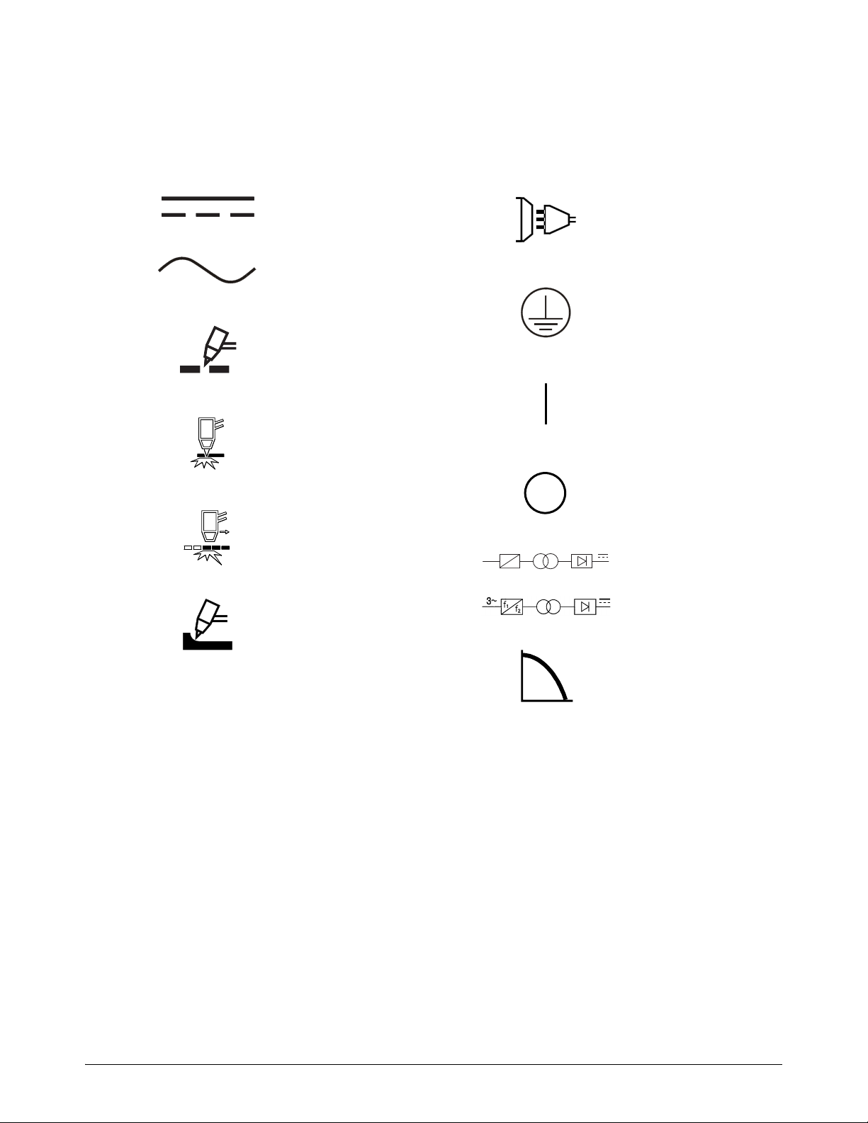
Install and Set Up the Plasma Power Supply
2
Direct current (DC)
Alternating current (AC)
Plasma torch cutting
Plate metal cutting
Expanded metal cutting
Gouging
AC input power
connection
The terminal for the
external protective (earth)
conductor
Power is ON
Power is OFF
An inverter-based power
source, either 1-phase or
3-phase
Volt/amperage curve,
“drooping” characteristic
f
1
f
2
1~
IEC symbols
The following symbols can appear on the data plate, control labels, switches, light-emitting diodes
(LEDs), and liquid-crystal display (LCD) screen, if applicable.
Powermax65/85/105 SYNC Operator Manual 810470 31

Install and Set Up the Plasma Power Supply
2
Acoustical noise levels
This plasma system can make more than the permitted acoustical noise levels as defined by national
and local codes. Always put on correct ear protection when cutting or gouging. Any acoustical
noise measurements taken are related to the specific environment in which the system is used.
Refer to Noise can damage hearing in the Safety and Compliance Manual (80669C).
In addition, you can find an Acoustical Noise Data Sheet for your system at
www.hypertherm.com/docs. In the search box, enter data sheet.
Radio frequency identification (RFID) specifications
The Hypertherm RFID near-field wireless communication system contains the following
components:
A passive RFID tag in the Hypertherm cartridge
A wireless radio transceiver on the printed circuit board (PCB) in the SmartSYNC torch:
Operating frequency: 13.56 MHz
Protocol: ISO/IEC 15693
Maximum range: 8 mm (0.32 inch)
Maximum transmit power: 104 mW
32 810470 Operator Manual Powermax65/85/105 SYNC

Install and Set Up the Plasma Power Supply
2
Cutting specifications
Recommended cut capacity – hand cutting
Material thickness
Recommended capacity Powermax65 SYNC Powermax85 SYNC Powermax105 SYNC
Cut capacity at 500 mm/min
(20 in/min)*
Cut capacity at 250 mm/min
(10 in/min)*
Severance capacity at 125 mm/min
(5 in/min)*
* Cut capacity speeds are not necessarily maximum speeds. They are the speeds that are required to be rated at that
thickness.
19 mm (3/4 in.) 25 mm (1 in.) 32 mm (1-1/4 in.)
25 mm (1 in.) 32 mm (1-1/4 in.) 38 mm (1-1/2 in.)
32 mm (1-1/4 in.) 38 mm (1-1/2 in.) 51 mm (2 in.)
Recommended pierce capacity
Material thickness
Pierce capacity Powermax65 SYNC Powermax85 SYNC Powermax105 SYNC
For handheld cutting, or mechanized
cutting with programmable torch height
control
For mechanized cutting without
programmable torch height control
16 mm (5/8 in.) 19 mm (3/4 in.) 22 mm (7/8 in.)
13 mm (1/2 in.) 16 mm (5/8 in.) 19 mm (3/4 in.)
Maximum cut speeds (mild steel)
Maximum cut speed*
Material thickness Powermax65 SYNC Powermax85 SYNC Powermax105 SYNC
6 mm (1/4 in.) 3,683 mm/min (145 in/min) 5,080 mm/min (200 in/min) 5,588 mm/min (220 in/min)
13 mm (1/2 in.) 1,270 mm/min (50 in/min) 1,778 mm/min (70 in/min) 2,413 mm/min (95 in/min)
19 mm (3/4 in.) 610 mm/min (24 in/min) 914 mm/min (36 in/min) 1,270 mm/min (50 in/min)
25 mm (1 in.) 305 mm/min (12 in/min) 533 mm/min (21 in/min) 762 mm/min (30 in/min)
32 mm (1-1/4 in.) Not applicable 330 mm/min (13 in/min) 508 mm/min (20 in/min)
* Maximum cut speeds are the results of Hypertherm’s laboratory testing. Actual cutting speeds can be different
related to different cutting applications.
Powermax65/85/105 SYNC Operator Manual 810470 33

Install and Set Up the Plasma Power Supply
2
Clearance:
>0.25 m (10 inches)
3m (10ft)
Gouge capacity
65 A 85 A 105 A
Maximum Removal metal removal rate
on mild steel
Maximum Control metal removal rate on
mild steel
4.0 kg/hr (8.8 lb/hr) 8.2 kg/hr (18.2 lb/hr) 8.6 kg/hr (19.1 lb/hr)
2.3 kg/hr (5.1 lb/hr) 4.8 kg/hr (10.6 lb/hr) 7.2 kg/hr (15.9 lb/hr)
Set up the plasma power supply
CHANCE OF ELECTRIC SHOCK
Never cut under water or submerge the torch in water. Electric shock can cause serious
injury.
WARNING
WARNING
TOXIC FUMES CAN CAUSE INJURY OR DEATH
Some metals, including stainless steel, can release toxic fumes when cut. Make sure that
your work site has sufficient ventilation to make sure that the air quality level meets all local
and national standards and regulations. Refer to the Safety and Compliance Manual
(80669C) for more information.
Do not use the plasma power supply in rain
or snow.
Put the plasma power supply near the
line-disconnect switch or near an approved
power receptacle for your installation. The
plasma power supply has a 3 m (10 ft)
power cord.
Keep at least 0.25 m (10 inches) of space
around the plasma power supply for
sufficient ventilation.
34 810470 Operator Manual Powermax65/85/105 SYNC

2
Put the plasma power supply on a stable,
>10°
level surface before using. The plasma
power supply can tip over if set at an angle
greater than 10°.
Do not put the plasma power supply on its
side. Doing so can cause a blockage of the
air circulation necessary to keep internal
components cool.
Install and Set Up the Plasma Power Supply
Powermax65/85/105 SYNC Operator Manual 810470 35

Install and Set Up the Plasma Power Supply
2
233 mm
(9.2 inches)
483 mm
(19 inches)
430 mm
(17 inches)
354 mm
(13.9 inches)
Plasma power supply dimensions and weights
Powermax65 SYNC and Powermax85 SYNC
Figure 1 – Powermax65 SYNC and Powermax85 SYNC dimensions
Table 1 – Powermax65 SYNC and Powermax85 SYNC weights with power cords
Powermax65 SYNC Powermax85 SYNC
200 V – 600 V CSA 380 V CCC / 400 V CE 200 V – 600 V CSA 380 V CCC / 400 V CE
24.3 kg (54 lb) 20.6 kg (45 lb) 27.2 kg (60 lb) 23.5 kg (52 lb)
For hand torch weights, refer to Weights on page 110. For machine torch
weights, refer to the Powermax65/85/105 SYNC Mechanized Cutting
Guide (810480).
36 810470 Operator Manual Powermax65/85/105 SYNC

2
Powermax105 SYNC
274 mm
(10.8 inches)
592 mm
(23.3 inches)
508 mm
(20 inches)
436 mm
(17 inches)
Install and Set Up the Plasma Power Supply
Figure 2 – Powermax105 SYNC dimensions
Table 2 – Powermax105 SYNC weight with power cord
200 V – 600 V CSA 230 V – 400 V CE 380 V CCC / 400 V CE
39.7 kg (88 lb) 39.5 kg (87 lb) 36.2 kg (80 lb)
Work lead weights
Work lead Powermax65 SYNC Powermax85 SYNC Powermax105 SYNC
7.6 m (25 ft) 1.3 kg (2.9 lb) 1.6 kg (3.6 lb) 2.3 kg (5.1 lb)
15 m (50 ft) 2.3 kg (5.0 lb) 3.0 kg (6.5 lb) 4.2 kg (9.25 lb)
23 m (75 ft) 3.1 kg (6.9 lb) 4.2 kg (9.25 lb) 6.1 kg (13.4 lb)
For hand torch weights, refer to Weights on page 110. For machine torch
weights, refer to the Powermax65/85/105 SYNC Mechanized Cutting
Guide (810480).
Powermax65/85/105 SYNC Operator Manual 810470 37
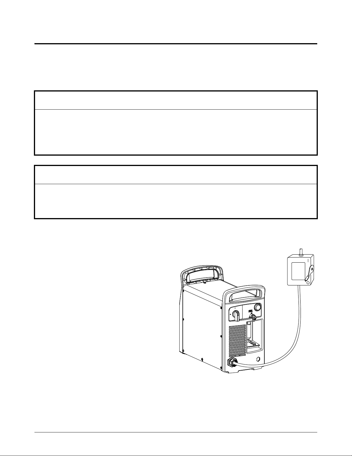
Install and Set Up the Plasma Power Supply
2
Connect to electrical power
Use the Hypertherm input current ratings to select conductor sizes for power connection and
installation instructions. The Hypertherm ratings are designated HYP on the data plate on the rear of
the plasma power supply. Use the higher HYP input current value for installation purposes. Refer to
Find system specifications on the data plate on page 28 for a sample data plate.
NOTICE
Protect the circuit with appropriately sized time-delay fuses and a line-disconnect switch.
The maximum output voltage changes related to input voltage and the circuit’s amperage. Because the
current draw changes during startup, time-delay fuses are recommended. Time-delay fuses are
resistant to currents up to 10 times the rated value for short periods of time.
NOTICE
Do not use phase converters to supply 3-phase power to your Powermax plasma power supply.
Hypertherm does not warranty systems that have been damaged as a result of poor power quality from
phase converters or incoming line power.
Install a line-disconnect switch
Use a line-disconnect switch for
each plasma power supply so that
the operator can stop the incoming
power quickly in an emergency.
Put the switch in a location that it is
easily accessible to the operator.
Installation must be done by a
licensed electrician according to
national and local codes.
The interrupt level of the switch
must equal or be more than the
continuous rating of the fuses.
The switch must also do the
following:
Isolate the electrical equipment
and disconnect all live
conductors from the incoming
supply voltage when in the OFF position.
Have one OFF and one ON position that are clearly marked with O (OFF) and I (ON).
Have an external operating handle that can be locked in the OFF position.
38 810470 Operator Manual Powermax65/85/105 SYNC

Install and Set Up the Plasma Power Supply
2
Contain a power-operated mechanism that operates as an emergency stop.
Have approved time-delay fuses installed. Refer to Voltage configurations on page 40
for recommended fuse sizes.
Powermax65/85/105 SYNC Operator Manual 810470 39

Install and Set Up the Plasma Power Supply
2
Requirements for grounding
To make sure of personal safety and correct operation, and to decrease electromagnetic
interference (EMI), the plasma power supply must be correctly grounded.
The plasma power supply must be grounded through the power cord according to
national and local electrical codes.
1-phase service must be of the 3-wire type with a green or green/yellow wire for the
protective earth ground and must comply with national and local requirements. Do not use
a 2-wire service.
3-phase service must be of the 4-wire type with a green or green/yellow wire for protective
earth ground and must comply with national and local requirements.
Refer to the Safety and Compliance Manual (80669C) for more information on grounding.
For mechanized cutting systems, refer to EMI grounding and shielding best practices in the
Powermax65/85/105 SYNC Mechanized Cutting Guide (810480).
Rated output (cutting power) of the plasma power supply
Wattage output shows a plasma power supply’s cutting power more than its amperage output. The
rated outputs for the systems are as follows:
Powermax65 SYNC Powermax85 SYNC Powermax105 SYNC
Maximum output amperage 20 A – 65 A 25 A – 85 A 30 A – 105 A
Maximum rated output voltage 139 VDC 143 VDC 160 VDC
Cutting power 9.0 kW 12.2 kW 16.8 kW
To calculate the cutting power in watts (W), multiply the maximum output amperage (A) by the
maximum rated output voltage (VDC). For example:
65 A x 139 VDC = 9035 W (9.0 kW)
Voltage configurations
The plasma power supply automatically adjusts for correct operation at the current input voltage.
You do not have to change or rewire components. But you must do the following:
Install the Hypertherm cartridge in the torch. Refer to Step 3 – Install the cartridge on
page 64.
Make sure that the output current (A) is correct for the cartridge that you installed. If
necessary, turn the adjustment knob on the front panel to adjust the output current. Refer to
Step 6 – Adjust the output current (A) and operating mode if necessary on page 70.
40 810470 Operator Manual Powermax65/85/105 SYNC

Install and Set Up the Plasma Power Supply
2
To operate the plasma power supply at full output and at its rated duty cycle (refer to Prevent
overheating on page 81), you must make your electrical service the correct size. The following
tables show the maximum rated output for typical input voltages. The output setting that you use
relates to the thickness of the workpiece and the limit of the input power to the plasma power
supply.
The recommended fuse sizes let spikes in input current occur when you
stretch the plasma arc. Stretching the plasma arc is common in some
applications, such as gouging.
Powermax65 SYNC
CSA configurations (1-phase)
Input voltage at 50 Hz/60 Hz* 200 V – 208 V 230 V – 240 V 480 V
Input current at rated output (65 A × 139 VDC = 9.0 kW) 52 A / 50 A 44 A 22 A
Input current during arc stretch 74 A 74 A 38 A
Fuse (time-delay) 80 A 80 A 40 A
* All models have a voltage tolerance of +10% / -15%.
CSA configurations (3-phase)
Input voltage at 50Hz/60Hz* 200V– 208V 230V– 240V 400V 480V – 600V
Input current at rated output
(65 A × 139 VDC = 9.0 kW)
Input current during arc stretch 45 A 45 A 27 A 23 A
Fuse (time-delay) 50 A 50 A 30 A 25 A
* All models have a voltage tolerance of +10% / -15%.
32 A / 31 A 27 A 15 A 13 A
CE/CCC configurations (3-phase)
Input voltage at 50 Hz/60 Hz* 380 V 400 V
Input current at rated output (65 A × 139 VDC = 9.0 kW) 15.5 A 15 A
Input current during arc stretch 27 A 27 A
Fuse (time-delay) 30 A 30 A
* All models have a voltage tolerance of +10% / -15%.
Powermax65/85/105 SYNC Operator Manual 810470 41

Install and Set Up the Plasma Power Supply
2
Powermax85 SYNC
CSA configurations (1-phase)
Input voltage at 50 Hz/60 Hz* 200 V – 208 V 230 V – 240 V 480 V
Input current at rated output (85 A × 143 VDC = 12.2 kW) 70 A / 68 A 58 A 29 A
Input current during arc stretch 98 A 98 A 50 A
Fuse (time-delay) 100 A 10 0 A 50 A
* All models have a voltage tolerance of +10% / -15%.
CSA configurations (3-phase)
Input voltage at 50 Hz/60 Hz* 200 V – 208 V 230 V – 240 V 400 V 480 V 600 V
Input current at rated output
(85 A × 143 VDC = 12.2 kW)
Input current during arc stretch 60 A 60 A 38 A 31 A 30 A
Fuse (time-delay) 60 A 60 A 40 A 30 A 30 A
* All models have a voltage tolerance of +10% / -15%.
42 A / 40 A 35 A 21 A 18 A 17 A
CE/CCC configurations (3-phase)
Input voltage at 50 Hz/60 Hz* 380 V 400 V
Input current at rated output (85 A × 143 VDC = 12.2 kW) 20.5 A 19.5 A
Input current during arc stretch 38 A 38 A
Fuse (time-delay) 40 A 40 A
* All models have a voltage tolerance of +10% / -15%.
42 810470 Operator Manual Powermax65/85/105 SYNC

Install and Set Up the Plasma Power Supply
2
Powermax105 SYNC
CSA configurations (3-phase)
Input voltage at 50Hz/60Hz* 200V 208V 240V 480V 600V
Input current at rated output
(105 A x 160 VDC = 16.8 kW)
Input current during arc stretch 82 A 82 A 78 A 40 A 35 A
Fuse (time-delay) 80 A 80 A 80 A 40 A 40 A
* All models have a voltage tolerance of +10% / -15%.
58 A 56 A 49 A 25 A 22 A
230 V – 400 V CE configurations (3-phase)
Input voltage at 50Hz/60Hz* 230V 400V
Input current at rated output (105 A x 160 VDC = 16.8 kW) 50 A 29 A
Input current during arc stretch 80 A 46 A
Fuse (time-delay) 80 A 50 A
* All models have a voltage tolerance of +10% / -15%.
380 V CCC / 400 V CE configurations (3-phase)
Input voltage at 50 Hz/60 Hz* CCC 380 V CE 400 V
Input current at rated output (105 A x 160 VDC = 16.8 kW) 30 A 28 A
Input current during arc stretch 42 A 44 A
Fuse (time-delay) 50 A 50 A
* All models have a voltage tolerance of +10% / -15%.
Powermax65/85/105 SYNC Operator Manual 810470 43

Install and Set Up the Plasma Power Supply
2
Prepare the power cord and plug
Install the power plug
A 3 m (10 foot) 3-phase power cord with the following specifications is included with all
Powermax65 SYNC, Powermax85 SYNC, and Powermax105 SYNC plasma power supplies. Refer
to Figure 3 on page 45.
This power cord does not come with a plug. To operate the plasma power supply, you must first
have a licensed electrician install an approved plug on the power cord – or connect the power cord
to a line-disconnect switch – according to all national and local electrical codes.
Model Configurations Power cord
Powermax65 SYNC
Powermax85 SYNC
Powermax105 SYNC
* Style H07RN-F cord is a harmonized, heavy-duty, flexible, rubber-insulated, black-neoprene-jacketed
multi-conductor IEC60245-4 / EN50525 European power cord with CE printed on the cord. The H07RN-F
cord used by Hypertherm also has CCC certification to GB/T 5013.4, with CCC printed on the cord.
200 V – 600 V CSA 8 AWG 4-wire
380 V CCC / 400 V CE 2.5 mm
200 V – 600 V CSA 8 AWG 4-wire
380 V CCC / 400 V CE 4 mm
200 V – 600 V CSA 6 AWG 4-wire
230 V – 400 V CE 10 mm
380 V CCC / 400 V CE 6 mm
Install the power cord (if necessary)
If your work site makes it necessary to install a different power cord than the one that comes with
the system, refer to Figure 3 on page 45 for instructions on how to prepare the power cord wires
and to connect them correctly in the plasma power supply.
2
, 4-wire style H07RN-F*
2
, 4-wire style H07RN-F*
2
, 4-wire HAR
2
, 4-wire H07RN-F* and HAR
44 810470 Operator Manual Powermax65/85/105 SYNC

2
L1
L2
L3
CSA power cord
(no ferrite cores)
CE/CCC power cord
(ferrite cores on power wires and
ground wire)
419 mm (16.5 inches)
M5 / #10 terminal ring,
approximately 12 mm
(0.5 inch) long
65/85
10 2 m m
(4 inches)
105
152 mm
(6 inches)
L1
L2
L3
Ground
Strain relief
Install and Set Up the Plasma Power Supply
Figure 3 – Install a power cord
For more instructions, refer to one of the following Field Service Bulletins:
Powermax65/85 SYNC Power Cord and Strain Relief Replacement (807020)
Powermax105 SYNC Power Cord and Strain Relief Replacement (810420)
Powermax65/85/105 SYNC Operator Manual 810470 45

Install and Set Up the Plasma Power Supply
2
Install a 1-phase power cord (CSA systems only) (if necessary)
You can operate a Powermax65/85 SYNC CSA plasma power supply on 1-phase power, but the
Powermax65/85 SYNC CE/CCC plasma power supply is 3-phase only.
To operate a Powermax65 SYNC CSA plasma power supply on 1-phase power, install a 10 mm
(8 AWG) 3-wire power cord. To operate a Powermax85 SYNC CSA plasma power supply on
1-phase power, install a 16 mm
by a licensed electrician.
Refer to the Powermax65/85 SYNC Power Cord and Strain Relief Replacement Field Service
Bulletin (807020) for instructions.
2
(6 AWG) 3-wire power cord. The power cord must be connected
Use an extension cord (if necessary)
Use an extension cord that meets the following requirements:
Is an approved wire gauge for the cord length and plasma power supply voltage
Complies with national and local codes
Extension cords can cause the machine to receive less input voltage than
the output of the circuit. This can put a limit on the operation of your
plasma power supply.
The following tables give the recommended gauge sizes for various lengths and input voltages.
The lengths in the tables are the length of the extension cord only; they do
not include the plasma power supply’s power cord.
2
46 810470 Operator Manual Powermax65/85/105 SYNC

2
Powermax65 SYNC systems
Install and Set Up the Plasma Power Supply
Table 3 – 65 A CSA
Extension cord length
< 3 m
(< 10 ft)
3 m – 7.5 m
(10 ft – 25 ft)
7. 5 m – 1 5 m
(25 ft – 50 ft)
(50 ft – 100 ft)
Input voltage (VAC) Phase Extension cord gauge
200 – 240 1
480 1
200 – 240 3
400/480 3
600 3
10 m m
(8 AWG)
2
4mm
(12 AWG)
2
6mm
(10 AWG)
2
4mm
(12 AWG)
2
4mm
(12 AWG)
10 m m2
(8 AWG)
4mm2
(12 AWG)
6mm2
(10 AWG)
4mm2
(12 AWG)
4mm2
(12 AWG)
10 m m2
(8 AWG)
4mm2
(12 AWG)
6mm2
(10 AWG)
4mm2
(12 AWG)
4mm2
(12 AWG)
2
Table 4 – 65 A CE/CCC
Extension cord length
< 3 m
(< 10 ft)
3 m – 7.5 m
(10 ft – 25 ft)
7. 5 m – 1 5 m
(25 ft – 50 ft)
(50 ft – 100 ft)
Input voltage (VAC) Phase Extension cord gauge
380 3 4 mm
400 3 4 mm
2
2
4mm
4mm
2
2
4mm
4mm
2
2
15 m – 30 m
16 mm2
(6 AWG)
6mm2
(10 AWG)
10 m m2
(8 AWG)
4mm2
(12 AWG)
4mm2
(12 AWG)
15 m – 30 m
2
4mm
2
4mm
30 m – 45 m
(100 ft – 150 ft)
25 mm2
(4 AWG)
6mm2
(10 AWG)
16 mm2
(6 AWG)
4mm2
(12 AWG)
4mm2
(12 AWG)
30 m – 45 m
(100 ft – 150 ft)
2
4mm
2
4mm
Powermax65/85/105 SYNC Operator Manual 810470 47

Install and Set Up the Plasma Power Supply
2
Powermax85 SYNC systems
Table 5 – 85 A CSA
Extension cord length
< 3 m
(< 10 ft)
3 m – 7.5 m
(10 ft – 25 ft)
7.5 m – 15 m
(25 ft – 50 ft)
(50 ft – 100 ft)
Input voltage (VAC) Phase Extension cord gauge
200 – 240 1
480 1
200 – 240 3
400/480 3
600 3
16 mm
(6 AWG)
2
6mm
(10 AWG)
2
10 m m
(8 AWG)
2
6mm
(10 AWG)
2
6mm
(10 AWG)
16 mm2
(6 AWG)
6mm2
(10 AWG)
10 mm2
(8 AWG)
6mm2
(10 AWG)
6mm2
(10 AWG)
16 mm2
(6 AWG)
6mm2
(10 AWG)
10 m m2
(8 AWG)
6mm2
(10 AWG)
6mm2
(10 AWG)
2
Table 6 – 85 A CE/CCC
Extension cord length
< 3 m
(< 10 ft)
3 m – 7.5 m
(10 ft – 25 ft)
7. 5 m – 1 5 m
(25 ft – 50 ft)
(50 ft – 100 ft)
Input voltage (VAC) Phase Extension cord gauge
380 3 6 mm
400 3 6 mm
2
2
6mm
6mm
2
2
6mm
6mm
2
2
15 m – 30 m
25 mm2
(4 AWG)
10 mm2
(8 AWG)
16 mm2
(6 AWG)
6mm2
(10 AWG)
6mm2
(10 AWG)
15 m – 30 m
2
6mm
2
6mm
30 m – 45 m
(100 ft – 150 ft)
35 mm2
(2 AWG)
10 m m2
(8 AWG)
25 mm2
(4 AWG)
6mm2
(10 AWG)
6mm2
(10 AWG)
30 m – 45 m
(100 ft – 150 ft)
2
6mm
2
6mm
48 810470 Operator Manual Powermax65/85/105 SYNC

2
Powermax105 SYNC systems
Install and Set Up the Plasma Power Supply
Table 7 – 200 V – 600 V CSA
Extension cord length
< 3 m
(< 10 ft)
3 m – 7.5 m
(10 ft – 25 ft)
7. 5 m – 1 5 m
(25 ft – 50 ft)
(50 ft – 100 ft)
Input voltage (VAC) Phase Extension cord gauge
200 – 240 3
480 – 600 3
16 mm
(6 AWG)
2
6mm
(10 AWG)
16 mm2
(6 AWG)
6mm2
(10 AWG)
16 mm2
(6 AWG)
6mm2
(10 AWG)
2
Table 8 – 230 V – 400 V CE
Extension cord length
< 3 m
(< 10 ft)
3 m – 7.5 m
(10 ft – 25 ft)
7. 5 m – 1 5 m
(25 ft – 50 ft)
(50 ft – 100 ft)
Input voltage (VAC) Phase Extension cord gauge
230 3 16 mm
400 3 10 mm
2
2
16 mm
10 m m
2
2
16 mm
10 m m
2
2
Table 9 – 380 V CCC / 400 V CE
Extension cord length
< 3 m
(< 10 ft)
3 m – 7.5 m
(10 ft – 25 ft)
7. 5 m – 1 5 m
(25 ft – 50 ft)
(50 ft – 100 ft)
15 m – 30 m
25 mm2
(4 AWG)
6mm2
(10 AWG)
15 m – 30 m
2
25 mm
2
10 m m
15 m – 30 m
30 m – 45 m
(100 ft – 150 ft)
35 mm2
(2 AWG)
6mm2
(10 AWG)
30 m – 45 m
(100 ft – 150 ft)
2
25 mm
2
10 m m
30 m – 45 m
(100 ft – 150 ft)
Input voltage (VAC) Phase Extension cord gauge
380 3 10 mm
400 3 10 mm
2
2
10 m m
10 m m
2
2
10 m m
10 m m
2
2
10 m m
10 m m
2
2
10 m m
10 m m
2
2
Powermax65/85/105 SYNC Operator Manual 810470 49

Install and Set Up the Plasma Power Supply
2
Use a generator (if necessary)
Make sure that you do the following when you use a generator:
Only use a generator that meets the plasma power supply’s requirements. Refer to
Powermax65 SYNC and Powermax85 SYNC systems on page 51 and
Powermax105 SYNC systems on page 52.
Adjust the output current (A) if necessary related to the rating, age, and condition of the
generator. Refer to Step 6 – Adjust the output current (A) and operating mode if necessary
on page 70.
Use one of the following recommended generators when full arc stretch is necessary, such
as for many gouging applications. These generators let spikes in input current occur when
you stretch the plasma arc.
15 kW generator for Powermax65 SYNC
20 kW generator for Powermax85 SYNC
30 kW generator for Powermax105 SYNC
If a fault occurs, set the power switch on the plasma power supply to OFF (O). Wait
approximately 1 minute before you set the power switch to ON (I).
Problems with input line voltage (fault codes 0-13-0, 0-60-n, and 0-61-0)
can occur more frequently with some generators. Refer to Troubleshoot
power-related problems with generators on page 148.
50 810470 Operator Manual Powermax65/85/105 SYNC

Install and Set Up the Plasma Power Supply
2
Powermax65 SYNC and Powermax85 SYNC systems
Generators used with a Powermax65 SYNC or Powermax85 SYNC must meet the requirements in
Ta bl e 10 and Tab le 1 1.
Table 10 – Voltage requirements
CSA
CE/CCC 3-phase: 50 Hz/60 Hz, 380 VAC / 400 VAC
* A 4-wire 1-phase connection (for example, NEMA 14-50R) is necessary for some generators. In this
condition, use an adapter to connect the plasma power supply’s 3-wire power cord plug (NEMA 6-50P) to
the 4-wire connector on the generator. Refer to Install a 1-phase power cord (CSA systems only) (if
necessary) on page 46 for more information.
Engine drive rating
20 kW 85 A Full
15 kW 70 A Decreased
15 kW 65 A Full
12 kW 65 A Decreased
12 kW 40 A Full
8 kW 40 A Decreased
8 kW 30 A Full
1-phase: 50 Hz/60 Hz, 230 VAC / 240 VAC*
3-phase: 50 Hz/60 Hz, 200 VAC – 600 VAC
Table 11 – Engine drive requirements
Plasma power supply output
current
Performance (arc stretch)
Powermax65/85/105 SYNC Operator Manual 810470 51

Install and Set Up the Plasma Power Supply
2
Powermax105 SYNC systems
Generators used with the Powermax105 SYNC must meet the requirements in Ta bl e 12 and
Ta bl e 1 3.
Table 12 – Voltage requirements
200 V – 600 V CSA 3-phase, 50 Hz/60 Hz, 200 VAC – 600 VAC
230 V – 400 V CE 3-phase, 50 Hz/60 Hz, 230 VAC – 400 VAC
380VCCC / 400 V CE 3-phase, 50Hz/60Hz, 380VAC / 400VAC
Table 13 – Engine drive requirements
Engine drive rating
30 kW 105 A Full
22.5 kW – 25 kW 105 A Decreased
20 kW 85 A Full
15 kW 70 A Decreased
15 kW 65 A Full
12 kW 65 A Decreased
12 kW 40 A Full
8 kW 40 A Decreased
8 kW 30 A Full
Plasma power supply output
current
Performance (arc stretch)
52 810470 Operator Manual Powermax65/85/105 SYNC

2
Connect the gas supply
123
EXPLOSION HAZARD
The filter bowl in the plasma power supply can explode if the gas pressure is more than
9.3 bar (135 psi). Never use more than the maximum gas pressure of 9.3 bar (135 psi).
Refer to the figure on page 54.
1. Get an inert-gas hose with the correct internal diameter .
For hoses that are less than 15 m (50 feet), use an internal diameter of 10 mm (3/8 inch)
or greater.
For hoses that are 15 m – 30 m (50 feet – 100 feet), use an internal diameter of 13 mm
(1/2 inch) or greater.
Install and Set Up the Plasma Power Supply
WARNING
Do not use hoses with an internal diameter less than 10 mm
(3/8 inch). Hoses that are too small can cause problems with cut quality
and cut performance.
2. Make sure that the correct gas inlet fitting is installed.
CSA models come with an industrial interchange quick-disconnect nipple with 1/4 NPT
threads . To install, tighten the fitting to 115 kg·cm (100 in·lb). The fitting comes with
thread sealant applied.
CE/CCC models come with a British Pipe Thread adapter G-1/4 BSPP with 1/4 NPT
threads . To install, tighten the adapter to 104 kg·cm (90 in·lb).
NOTICE
PTFE TAPE CAN CAUSE CLOGG ED VALVES, REG U LATORS, AND TORCHES
Never use PTFE tape on any joint preparation. Use only a liquid or paste thread sealant on male
threads.
Powermax65/85/105 SYNC Operator Manual 810470 53

Install and Set Up the Plasma Power Supply
2
1
2
3
3. Connect the gas hose to the gas inlet fitting. Refer to Inlet gas pressure requirements (while gas
is flowing) on page 57.
Gas supply source
Hypertherm recommends that air compressors supply air that meets the following requirements of
ISO Standard 8573-1:2010 Class 1.4.2*:
Maximum particle count in 1.0 m
Maximum water vapor pressure dewpoint: 3°C (37°F)**
Maximum oil concentration: 0.1 mg/m
* Important: Any air compressors that supply air to the cutting system must remove oil prior to air delivery.
** Speak to your air compressor manufacturer if you operate the cutting system in temperatures colder than 3°C (37°F)
or if you are unsure that the air compressor can comply with the ISO standard for air quality.
3
: • 20,000 at 0.1 microns – 0.5 microns
• 400 at 0.5 microns – 1.0 microns
• 10 at 1.0 microns – 5.0 microns
3
(for aerosol, liquid, and vapor)
NOTICE
DIRTY, OILY AIR CAN CAUSE DAMAGE TO THE AIR FILTER BOWL
Synthetic lubricants containing esters that are used in some air compressors can cause damage to the
polycarbonates in the air filter bowl. Add additional gas filtration if necessary.
54 810470 Operator Manual Powermax65/85/105 SYNC

2
Use shop-compressed gas or cylinder-compressed gas.
Use a high-pressure regulator on either type of gas supply. The regulator must be able
to deliver gas to the air inlet on the plasma power supply at the specified flow rate and
specified pressure.
Use only clean, moisture-free gas.
Oil, water, vapor, and other contaminants in the gas supply can cause damage to
internal components over time.
Poor gas supply quality causes:
Decreased cut quality and cut speeds
Decreased cut thickness capability
Decreased consumable life
To address these problems, use an optional air filtration system. Refer to Add additional
gas filtration (if necessary) on page 59.
High-pressure gas cylinders
Install and Set Up the Plasma Power Supply
WARNING
GAS CYLINDERS CAN EXPLODE IF DAMAGED
Gas cylinders contain gas under high pressure. If damaged, a cylinder can explode.
For high pressure regulators, comply with the manufacturer’s guidelines for safe
installation, operation, and maintenance.
Before plasma cutting with compressed gas, read the safety instructions in the Safety and
Compliance Manual (80669C). Failure to comply with safety instructions can cause
personal injury or equipment damage.
WARNING
EXPLOSION HAZARD – CUTTING WITH FLAMMABLE OR OXIDIZING GASES
Do not use flammable or oxidizing gases with Powermax systems. These gases can cause
explosive conditions during plasma cutting operations.
An example of an oxidizing gas is oxygen. Examples of flammable gases are acetylene,
propylene, methane, and pure hydrogen. Refer to the Safety and Compliance Manual
(80669C) for more information.
Powermax65/85/105 SYNC Operator Manual 810470 55

Install and Set Up the Plasma Power Supply
2
You can use the following gases to cut with this plasma power supply. Refer to Hypertherm plasma
power supply ratings on page 21 for requirements on gas quality.
Air
Nitrogen
Do NOT use oxygen to cut with Powermax systems
F5 (stainless steel only)
Refer to the Powermax65/85/105 SYNC Mechanized Cutting Guide (810480).
If you use high-pressure gas cylinders as the gas supply, then do the following:
Refer to the manufacturer’s specifications for installation and maintenance procedures of
high-pressure regulators.
Make sure that the cylinder has an adjustable high-pressure regulator with the following
capabilities:
Gas outlet pressures up to 9.3 bar (135 psi). Never use more than the maximum gas
pressure of 9.3 bar (135 psi).
The following gas flow rates:
Powermax65/85 SYNC: 210 slpm (450 scfh)
Powermax105 SYNC: 260 slpm (550 scfh)
Make sure that the cylinder valves are clean and free of oil, grease, and other contaminants.
Open each cylinder valve just long enough to blow out any dust that is possibly present.
Connect the supply hose correctly to the cylinder.
56 810470 Operator Manual Powermax65/85/105 SYNC

2
Inlet gas pressure requirements (while gas is flowing)
The following inlet gas pressure specifications apply for air, nitrogen, and F5 gases.
Maximum inlet pressure
Never exceed the maximum gas pressure of 9.3 bar (135 psi).
WARNING
EXPLOSION HAZARD
The filter bowl in the plasma power supply can explode if the gas pressure is more than
9.3 bar (135 psi). Never use more than the maximum gas pressure of 9.3 bar (135 psi).
Optimum inlet pressure
Install and Set Up the Plasma Power Supply
For optimum system performance, make sure that the inlet gas pressure stays between
7.6 bar– 8.3 bar (110 psi – 120 psi) while gas is flowing.
Keep the inlet gas pressure at the optimum range to make sure that system performance is good for
all the combinations of plasma power supply, torch lead length, and cutting and gouging processes
that you use.
Minimum inlet pressure
The following tables show the minimum inlet gas pressure requirements for each Powermax SYNC
system. Use the correct pressure for your combination of operating mode, cartridge type, and torch
lead length.
If your inlet gas pressure goes below these levels while gas is flowing, a fault condition can occur. A
pressure-related fault code on the LCD screen can be for a notification or for a condition that stops
the cutting process. Hypertherm recommends that you do the recommended steps to troubleshoot
the fault. Refer to Fault codes on page 132 and Examine the gas pressure on page 126.
Additional gas filtration installed between the gas supply and the plasma power supply can have an
effect on gas pressure and gas flow. Speak to the filter manufacturer about gas pressure
requirements. Hypertherm recommends that you install an inline pressure gauge at the gas inlet on
the back of the plasma power supply. Use this gauge to monitor the gas pressure at the plasma
power supply, after all external filtration.
Powermax65/85/105 SYNC Operator Manual 810470 57

Install and Set Up the Plasma Power Supply
2
Cutting
Torc h lea d le n gt h
7.6 m (25 ft) 15.2 m (50 ft) 22.9 m (75 ft)
Powermax65 SYNC
Powermax85 SYNC
Powermax105 SYNC 5.5 bar (80 psi) 5.9 bar (85 psi) 6.2 bar (90 psi)
5.2 bar (75 psi) 5.5 bar (80 psi) 5.9 bar (85 psi)
Maximum Control gouging
Torc h lea d le n gt h
7.6 m (25 ft) 15 m (50 ft) 23 m (75 ft)
Powermax65 SYNC
Powermax85 SYNC
Powermax105 SYNC
4.1 bar (60 psi) 4.5 bar (65 psi) 4.8 bar (70 psi)
Maximum Removal gouging
Torc h lea d le n gt h
7.6 m (25 ft) 15 m (50 ft) 23 m (75 ft)
Powermax65 SYNC
Powermax85 SYNC
Powermax105 SYNC
4.1 bar (60 psi) 4.5 bar (65 psi) 4.8 bar (70 psi)
Recommended gas inlet flow rates
Process
Cutting 210 slpm (450 scfh, 7.5 scfm) at a
Maximum Removal gouging 210 slpm (450 scfh, 7.5 scfm) at a
Maximum Control gouging 210 slpm (450 scfh, 7.5 scfm) at a
Refer to the Powermax65/85/105 SYNC Cut Charts Guide (810500MU) for flow rates specific to
each cutting process specified (related to the type of metal, the type of gas, and the output current).
Powermax65 SYNC and
Powermax85 SYNC
minimum 5.9 bar (85 psi)
minimum 4.8 bar (70 psi)
minimum 4.8 bar (70 psi)
Powermax105 SYNC
260 slpm (550 scfh, 9.1 scfm) at a
minimum 6.2 bar (90 psi)
260 slpm (550 scfh, 9.1 scfm) at a
minimum 4.8 bar (70 psi)
260 slpm (550 scfh, 9.1 scfm) at a
minimum 4.8 bar (70 psi)
58 810470 Operator Manual Powermax65/85/105 SYNC

2
Add additional gas filtration (if necessary)
Air filter bowl
Gas supply Water and
particle filter
Oil filter Plasma power
supply
Oil vapor filter
It is extremely important to keep a clean, dry gas line to do the following:
Prevent oil, water, dirt, and other contaminants from causing damage to internal
components.
Get optimal cut quality and consumable life.
Dirty, oily air is the root cause of many common
problems that occur in Powermax systems, and in
some conditions it can void the warranty on the
plasma power supply and on the torch. Refer to
the gas quality recommendations in the ratings
tables that start on page 21.
The plasma power supply contains a built-in air
filter. Regularly do a check of the filter element
inside the air filter bowl and replace as necessary.
Refer to Examine the air filter bowl and filter
element on page 177.
Install and Set Up the Plasma Power Supply
The built-in air filter must not take the place of sufficient external filtration. If you work in an
environment that is extremely warm and humid, or if work site conditions introduce oil, vapors, or
other contaminants into the gas line, install an external filtration system that cleans the gas supply
before it gets into the plasma power supply.
A 3-stage coalescing filtration system is recommended. A 3-stage filtering system works as follows
to clean contaminants from the gas supply.
The filtering system must be installed between the gas supply and the plasma power supply.
Additional gas filtration can make higher pressure from the gas supply
necessary. For the recommended gas inlet flow rate and pressure, refer to
Inlet gas pressure requirements (while gas is flowing) on page 57.
Powermax65/85/105 SYNC Operator Manual 810470 59

Install and Set Up the Plasma Power Supply
2
1
2
1
2
Hypertherm offers the following optional external filter kits:
Kit 128647: The Eliminizer moisture removal air filter removes water and dirt from the gas
supply. For more information, refer to the Optional Air Filter Kit and Element Replacement
Procedure Field Service Bulletin (804180).
Kit 428719: The oil removal air filter removes oil, oil vapor, and dirt from the gas supply.
For more information, refer to the Optional Oil Removal Air Filter Kit and Element
Replacement Field Service Bulletin (809610).
For additional parts related to these filter kits, refer to the
Powermax65/85/105 SYNC Parts Guide (810490).
If you use both external filters, install them in the order shown in Figure 4 to prevent damage to the
gas line and equipment.
Figure 4 – Optional Hypertherm external filters
60 810470 Operator Manual Powermax65/85/105 SYNC

Operate the Plasma System
Make sure that the plasma power supply is connected to gas and power
1. Connect the gas supply line to the fitting on the back of the plasma power supply. Refer to
page 53.
For gas supply requirements, refer to Gas supply source on page 54.
2. Make sure that the plasma power supply’s power cord is correctly connected to electrical power
according to national and local codes. Refer to Connect to electrical power on page 38, and
Prepare the power cord and plug on page 44.
Powermax65/85/105 SYNC Operator Manual 810470 61

Operate the Plasma System
3
Red button
Step 1 – Connect the torch lead
Always set the power
switch on the plasma
power supply to OFF (O)
before you connect or
disconnect a torch.
To connect a hand torch
or machine torch, push
the connector into the
receptacle on the front of
the plasma power supply.
The connector makes a
click when it is fully
engaged.
To disconnect the torch,
push the red button on
the connector and pull
the connector out of the receptacle.
62 810470 Operator Manual Powermax65/85/105 SYNC

Operate the Plasma System
3
Keyed opening at the top of the
work lead receptacle
Step 2 – Connect the work lead and work clamp
NOTICE
INCORRECT WORK LEADS CAN CAUSE AN UNSTABLE PLASMA ARC
Work leads are approved for specific amperages, lengths, and connectors. Make sure that you use a
work lead that is approved for your plasma power supply. Refer to the Powermax65/85/105 SYNC
Parts Guide (810490). The amperage of a work lead is identified near the rubber boot of the work lead
connector.
Work lead
1. Put the work lead connector in the
receptacle on the front of the plasma
power supply. Align the key on the
connector with the opening at the top of
the receptacle.
2. Push the work lead connector all the way
into the receptacle. Turn the connector
clockwise approximately 1/4 turn until the
connector is fully engaged and locked in
position.
NOTICE
LOOSE WORK LEADS CAN OVERHEAT
Anytime you move the work lead or the plasma power supply, examine the work lead connector to make
sure that it is fully connected to the plasma power supply and is not loose.
Powermax65/85/105 SYNC Operator Manual 810470 63

Operate the Plasma System
3
Work clamp
NOTICE
Do not attach the work clamp under water. If the plasma power supply is below the work clamp, water
can get into the plasma power supply through the work lead and cause severe damage.
Do not attach the work clamp to the portion of the workpiece to be cut away.
Hand cutting: The work clamp must be connected to the workpiece that you are cutting.
Mechanized cutting: If you are using this plasma power supply with a mechanized cutting
system, you can connect the work clamp directly to the cutting table or to the workpiece you
are cutting. Refer to your equipment manufacturer’s instructions.
Make sure that the work clamp
makes good metal-to-metal contact
with the workpiece or cutting table.
Remove rust, dirt, paint, coatings,
and other debris so that the work
clamp makes sufficient contact with
the workpiece or cutting table.
Attach the work clamp as close as
possible to the area being cut.
Step 3 – Install the cartridge
INSTANT-ON TORCHES – PLASMA ARC CAN CAUSE INJURY, BURNS
Ignition of the plasma arc occurs immediately when you pull the torch trigger. Before
changing the cartridge, one of the following steps is necessary. Whenever possible,
complete the first step.
Set the power switch on the plasma power supply to OFF (O).
OR
Move the torch-lock switch to the yellow lock (X) position. Pull the trigger to make
sure that the torch does not fire a plasma arc.
WARNING
64 810470 Operator Manual Powermax65/85/105 SYNC

3
Lock the torch
SmartSYNC torches include a switch that lets you lock the torch. This torch-lock switch prevents
the torch from firing accidentally, even when the plasma power supply is ON.
Use this switch to lock the torch when it is not in use, when it is necessary to change the
Hypertherm cartridge, or when it is necessary to move the plasma power supply or torch while the
plasma power supply is ON.
Tor ch LOCK position:
The yellow label with the “X” shows that the
torch is not prepared to fire.
Point the torch away from yourself and
others, and pull the trigger to make sure that
it does not fire.
Operate the Plasma System
When the torch is locked, the Fault LED
comes on, and the Torch Cap Sensor
icon and 0-50-1 fault code show on the
status screen.
You CAN install the cartridge.
Tor ch “ready to fire” position:
The green label with the “ ” shows that
the torch is prepared to fire.
Do NOT change the cartridge.
Powermax65/85/105 SYNC Operator Manual 810470 65

Operate the Plasma System
3
Tighten 1/4 turn to install.
Install the cartridge
Cartridges are not preinstalled on new
torches.
1. Make sure that the power switch on
the plasma power supply stays
OFF (O).
2. Make sure that the torch-lock switch
on the torch is set to the yellow
lock (X) position.
3. If this is a new torch, remove the vinyl
cap from the torch.
4. Install the correct Hypertherm
cartridge for your cutting or gouging
application.
Cutting and piercing with a
hand torch: Refer to Select
the correct cutting cartridge
on page 95.
Gouging with a hand torch:
Refer to Select the correct
gouging cartridge on
page 111.
Cutting, piercing, and
gouging with a machine
torch: Refer to the
Powermax65/85/105 SYNC
Mechanized Cutting Guide (810480).
66 810470 Operator Manual Powermax65/85/105 SYNC

3
Step 4 – Set the power switch to ON (I)
Set the power switch to ON (I). The
switch is on the rear panel of the
plasma power supply.
If the torch-lock switch is set
to the green “ready to
fire” ( ) position when you
set the power switch to ON,
the hand torch puts out a
puff of air. Refer to Warning
puffs of air (hand torches) on
page 68.
If the torch-lock switch is set
to the yellow lock (X)
position when you set the
power switch to ON, the
0-50-0 or 0-50-1 fault code
and Torch Cap Sensor icon
show on the status screen.
Refer to Fault code and LED behavior on page 69.
Operate the Plasma System
Powermax65/85/105 SYNC Operator Manual 810470 67

Operate the Plasma System
3
1
2
3
1
2
3
Step 5 – Unlock the SmartSYNC torch
1. Move the torch-lock switch to the green “ready
to fire” ( ) position.
2. Hand torch: Pull the torch trigger 1 time to get
the warning puffs of air.
Machine torch: Send a START / STOP
command from the CNC to fire a plasma arc.
There are no warning puffs of air.
3. Hand torch: When the warning puffs of air
stop, the torch is prepared to fire a plasma arc.
If you see a fault code and fault icon on the status
screen, remove the fault condition before you
continue. Refer to Fault codes on page 132.
Warning puffs of air (hand torches)
The following happens on SmartSYNC hand torches the first time that you try to fire the torch after
moving the torch-lock switch to the yellow lock (X) position and then back to the green “ready to
fire” ( ) position:
The plasma arc does not fire.
The torch quickly puts out multiple puffs of air. You can feel a light tap in the torch handle with each
puff of air.
The plasma power supply makes a pressure-release sound that you can hear with each puff of air.
This feedback is a warning. It does not identify a fault condition. It tells you that the torch is
unlocked and will fire a plasma arc the next time that you pull the trigger.
68 810470 Operator Manual Powermax65/85/105 SYNC

3
Fault code and LED behavior
1
2 3
Yel lo w Ye llo w
Green
1
2
312
3
On the plasma power supply:
Operate the Plasma System
When you set the torch-lock switch to the yellow lock (X) position while the plasma power supply
stays ON, the Fault light-emitting diode (LED) comes on and the 0-50-1 fault code and Torch Cap
Sensor icon show.
After you install the cartridge and set the torch-lock switch to the green “ready to fire” ( )
position, the Fault LED goes off and the fault code changes to 0-50-2.
Hand torch: After the torch puts out the warning puffs of air, the 0-50-2 fault code goes off.
Machine torch: The 0-50-2 fault code shows for approximately 1 second and then goes off.
When you start the plasma power supply while the torch-lock switch is in
the yellow lock (X) position, the system shows the 0-50-0 fault code
instead of 0-50-1. Move the torch-lock switch to the green “ready to fire”
( ) position to continue.
On the SmartSYNC hand torch:
When you set the torch-lock switch to the yellow lock (X) position while the plasma power supply
stays ON, the LED on the hand torch changes from green to yellow.
When you install the Hypertherm cartridge and set the torch-lock switch to the green “ready to
fire” ( ) position, the LED on the hand torch stays yellow.
After the torch puts out the warning puffs of air, the LED changes from yellow to green.
Powermax65/85/105 SYNC Operator Manual 810470 69

Operate the Plasma System
3
Step 6 – Adjust the output current (A) and operating mode if necessary
1. Make sure that the output current (A) is correct for your application.
The plasma power supply automatically sets the output current related to the type of
Hypertherm cartridge that you install. For example, when you install a 65 A Hypertherm
cartridge, the plasma power supply sets the output current to 65 A.
Turn the adjustment knob as necessary to set the output current in
increments of 1 A. You can also use the hand torch to set the output
current. Refer to page 71.
Move the torch-lock switch to the green “ready to fire” ( ) position
before you adjust the output current.
When you adjust the current, a scale identifies the lowest and highest possible amperage
setting related to the plasma power supply and Hypertherm cartridge.
2. Make sure that the operating mode is correct for your application.
The plasma power supply automatically sets the operating mode related to the type of
Hypertherm cartridge that you install.
When you install a Hypertherm cutting cartridge, the plasma power supply goes to
Cut mode. Gouge mode is not available.
When you install a Hypertherm gouging cartridge, the plasma power supply goes to
Gouge mode. Cut mode and Expanded Metal mode are not available.
You can adjust the operating mode manually if necessary. Refer to page 75. Move the
torch-lock switch to the green “ready to fire” ( ) position before you set the operating
mode.
The plasma power supply also automatically sets the gas pressure for optimum cutting
related to the operating mode, the torch type, the Hypertherm cartridge type, and the
length of the torch lead.
70 810470 Operator Manual Powermax65/85/105 SYNC

3
Step 7 – Use the SmartSYNC torch
Use the hand torch
Use the methods in the following sections to cut and gouge correctly:
Cut with the Hand Torch on page 93
Gouge with the Hand Torch on page 111
Adjust the amperage from the hand torch
The plasma power supply automatically sets the output current (A) related to the type of Hypertherm
cartridge that you install. For example, when you install a 65 A Hypertherm cartridge, the plasma
power supply sets the output current to 65 A.
If necessary, you can adjust the output
current (A) from the SmartSYNC hand
torch.
Operate the Plasma System
Push the button on the amperage
-adjustment control to move the current
setting from one preset amperage to
another.
The amperage for each setting changes
related to the Hypertherm cartridge and
plasma power supply that you are using.
Refer to Amperage settings by plasma
power supply and cartridge on page 72.
Powermax65/85/105 SYNC Operator Manual 810470 71

Operate the Plasma System
3
7
1
2
3
4
5
6
7
1
2
3
4
5
6
7
1
2
3
4
5
6
Amperage settings by plasma power supply and cartridge
Powermax65 SYNC
Cartridge type
45 A 65 A
45 A 65 A
35 A 60 A
25 A 55 A
45 A
Powermax85 SYNC
Powermax105 SYNC
20 A
35 A
25 A
20 A
Cartridge type
45 A 65 A 85 A
45 A 65 A 85 A
35 A 55 A 75 A
30 A 50 A 65 A
45 A 55 A
35 A 45 A
25 A
35 A
25 A
25 A
Cartridge type
45 A 65 A 85 A 105 A
45 A 65 A 85 A 105 A
35A55A75A95A
50 A 65 A 85 A
45 A 55 A 65 A
72 810470 Operator Manual Powermax65/85/105 SYNC
30 A
35 A 45 A 55 A
35 A 45 A
30 A
30 A 30 A

3
Use the machine torch
Green = torch is
prepared to cut
Yel lo w = torch is locked, or there is a
fault condition
LED OFF = system is
in Cut mode
LED ON = system is in
Gouge mode
Red = the cartridge is at end-of-life, or
an internal system component is
possibly faulty
Use the methods in the Powermax65/85/105 SYNC Mechanized Cutting Guide (810480) to cut
and gouge correctly.
What occurs during and after cutting
Temperature control
Postflow – After you complete a cut and release
the torch trigger, air continues to flow from
the torch to decrease the temperature of the
cartridge. This is referred to as postflow.
Always let postflow complete before you
remove a cartridge.
Fan activity – The cooling fan inside the plasma
power supply automatically comes on as
necessary during and after cutting to decrease the temperature of internal components.
Operate the Plasma System
Hand torch LED behavior
Powermax65/85/105 SYNC Operator Manual 810470 73

Operate the Plasma System
3
1
1
Adjust the gas pressure manually
In automatic gas pressure mode, the plasma power supply automatically sets the gas pressure for
optimum cutting related to the operating mode, the torch type, the Hypertherm cartridge type, and
the length of the torch lead. But if it is necessary to adjust the gas pressure for a specific
application, you can use manual gas pressure mode to do so.
Manual gas pressure mode must be used only by experienced operators.
1. Move the torch-lock switch to the green “ready to fire” ( ) position.
2. Push and hold until the green LED next to the button comes on to go into manual gas
pressure mode (approximately 2 seconds).
3. If necessary, push until the selection cursor points to the gas pressure
setting.
4. Turn the adjustment knob to adjust the gas pressure to the necessary level. The
arrow next to the pressure bar moves up and down as you adjust the pressure.
In many conditions, you can increase and decrease the gas pressure a maximum
of 0.7 bar (10 psi). The acceptable range can change if the cartridge you are
using has a smaller limit. If the bottom of the vertical bar is shaded, as shown to
the right, the system does not let you decrease the gas pressure below the top of
the shaded area.
.
74 810470 Operator Manual Powermax65/85/105 SYNC

3
Go back to automatic gas pressure mode
To go back to automatic gas pressure mode, push . The LED next to the button goes off.
The system also goes back to automatic gas pressure mode when you install a different type of
cartridge.
When you change from manual gas pressure mode to automatic gas pressure mode,
the plasma power supply automatically sets the gas pressure related to the Hypertherm
cartridge, but the amperage setting stays the same.
When you change from automatic gas pressure mode to manual gas pressure mode,
the plasma power supply uses the last manual gas pressure that you set, and the amperage
setting stays the same.
When you do a quick restart or a cold restart of the plasma power supply in manual
gas pressure mode, the plasma power supply keeps the last manual gas pressure and
amperage that you set unless you install a different type of cartridge.
Adjust the operating mode manually
Operate the Plasma System
The plasma power supply automatically sets the operating mode related to the type of Hypertherm
cartridge that you install.
When you install a Hypertherm cutting cartridge or FineCut
cartridge, the plasma power supply goes to Cut mode.
Push the button to move from Cut mode to Expanded Metal
mode.
Move the torch-lock switch to the green “ready to fire” ( )
position before you set the operating mode.
Gouge mode is not available.
When you install a Hypertherm gouging cartridge, the plasma
power supply goes to Gouge mode.
Cut mode and Expanded Metal mode are not available.
Powermax65/85/105 SYNC Operator Manual 810470 75

Operate the Plasma System
3
Cut expanded metal
Expanded metal has a slotted or mesh pattern. Cutting expanded metal causes cartridges to wear
more quickly because a continuous pilot arc is necessary. A pilot arc occurs when the torch is fired
but the plasma arc is not in contact with the workpiece.
Do these steps to cut expanded metal:
1. Install a Hypertherm cutting cartridge or FineCut cartridge.
2. Move the torch-lock switch to the green “ready to fire” ( )
position.
3. Push the button to move from Cut mode to Expanded Metal
mode.
Go back to automatic setting of the operating mode
When you manually set the operating mode, the plasma power supply keeps that setting
until you install a different type of Hypertherm cartridge or you install a different torch.
Do not set the operating mode when the torch-lock switch is in the yellow lock (X)
position. When you unlock the torch, the plasma power supply automatically sets the
operating mode to match the type of cartridge installed.
If you manually set the operating mode and then replace the Hypertherm cartridge with a
new cartridge of the same type, the plasma power supply keeps the operating mode that
you set.
The plasma power supply also keeps your setting if you do a quick restart or a cold
restart.
A type of Hypertherm cartridge refers to the amperage of the cartridge
and to its application, such as gouging, standard drag-cutting, FineCut, or
mechanized. Each type of Hypertherm cartridge has a different part
number.
76 810470 Operator Manual Powermax65/85/105 SYNC

3
Monitor cartridge data
Monitor data for individual cartridges
Each Hypertherm cartridge contains data about how it has been used. You can monitor this data if
necessary. For example, you can compare data between Hypertherm cartridges if one cartridge had
significantly better life than another cartridge, or if you want to calculate the average cartridge life
over a period of time.
You can also use the Hypertherm cartridge reader accessory to monitor Hypertherm cartridge use.
Refer to the Powermax65/85/105 SYNC
Dashboard User Guide (811460).
To see this information, go to the Cartridge Data screen (CARTRIDGE DATA 1):
1. Push and hold for 2 seconds to go to the main menu screen.
2. Turn the adjustment knob to go to . Push to select it.
Operate the Plasma System
Hypertherm Cartridge for Powermax SYNC Reader and
3. Turn the adjustment knob to go to , and push to select it. The Cartridge Data
screen (CARTRIDGE DATA 1) shows.
4. When you are done, push the button to go back to the status screen.
The following fields show the use data for the installed Hypertherm cartridge:
STA – This field shows the total number of pilot arc starts that the Hypertherm cartridge has done in
its life.
XFR – This field shows the total number of arc transfers that the Hypertherm cartridge has done in
its life.
Powermax65/85/105 SYNC Operator Manual 810470 77

Operate the Plasma System
3
PT – This field shows the cumulative pilot arc time that the Hypertherm cartridge has had in its life,
in hours (HH), minutes (MM), and seconds (SS): HH:MM:SS.
XT – This field shows the cumulative arc transfer time that the Hypertherm cartridge has had in its
life, in hours (HH), minutes (MM), and seconds (SS): HH:MM:SS.
You can see this same data for the life of the plasma power supply. Refer to Power Supply Data
screen on page 162.
Show cartridge data on the status screen
You can show the cartridge data for pilot arc starts (STA) and arc transfer time (XT) on the status
screen. When you set the STA/XT field to on, these values stay on the status screen until you set
the STA/XT field to off.
1. Push and hold for 2 seconds to go to the main menu screen.
2. Turn the adjustment knob to go to . Push to select it.
3. Turn the adjustment knob to go to , and push to select it. The LCD Display screen
(LCD DISPLAY) shows.
4. Turn the adjustment knob to go to the STA/XT field, and push to select it.
78 810470 Operator Manual Powermax65/85/105 SYNC

3
5. Turn the adjustment knob to set the STA/XT field
to on: .
6. Push to apply the setting.
7. Push to go back to the status screen.
The STA and XT fields now show on the screen.
Operate the Plasma System
Powermax65/85/105 SYNC Operator Manual 810470 79

Operate the Plasma System
3
LED is red
LED flashes yellow
When to replace the cartridge (fault code 0-32-n)
The system has a cartridge end-of-life detection feature that tells you when to install a new
Hypertherm cartridge. This feature helps to prevent damage to the torch. You can choose to replace
the cartridge before it gets to this condition if the cut quality is no longer satisfactory. Refer to Get
the most out of your cartridges on page 106.
When it is necessary to replace a cartridge, replace the full cartridge with a new one. Do not
try to disassemble the cartridge. No maintenance is necessary on the cartridge except possibly to
remove molten metal from the tip of the cartridge.
The 0-32-0 and 0-32-1 fault codes identify the cartridge end-of-life condition, as follows:
The 0-32-0 fault code shows when the system first senses that the Hypertherm cartridge is
at end-of-life. The LED on the hand torch also changes to red. To remove the fault code,
install a new cartridge.
If you restart the system and try to use the same cartridge, the 0-32-1 fault code shows
to remind you that the cartridge is at end-of-life. The LED on the hand torch also flashes
yellow. Hypertherm strongly recommends that you install a new cartridge.
If you continue to try to cut with a cartridge that is in an end-of-life condition, the 0-32-0
fault code shows again and stops the torch from firing.
80 810470 Operator Manual Powermax65/85/105 SYNC

3
Conditions when cartridge end-of-life detection is disabled
The plasma power supply temporarily disables the Hypertherm cartridge end-of-life detection
feature when one of the following conditions occurs:
You install a FineCut hand cutting cartridge.
You set the output current below 40 A for any type of Hypertherm cartridge.
Prevent overheating
The duty cycle ratings help you to know how to operate a Powermax system without overheating it.
Duty cycle – Percentage of time during a 10-minute interval that a plasma arc can stay on without
causing the plasma power supply to overheat.
For a complete list of duty cycle specifications for all of the plasma power supply
configurations, refer to the following sections:
Powermax65 SYNC: Refer to Powermax65 SYNC on page 22.
Operate the Plasma System
Powermax85 SYNC: Refer to Powermax85 SYNC on page 24.
Powermax105 SYNC: Refer to Powermax105 SYNC on page 26.
Table 14 – Duty cycle example for a Powermax65 SYNC
Output current Duty cycle*
Powermax65 SYNC
65 A 50%
46 A 100%
* Assumes ambient operating temperature of 40°C (104°F).
If you cut for more than the recommended duty cycle and the plasma power supply overheats, the
following occurs:
The plasma arc stops.
The temperature fault icon comes on.
The cooling fan inside the plasma power supply continues to operate.
When the plasma power supply overheats, do the following:
Leave the plasma power supply on to let the fan cool the plasma power supply.
Wait for the temperature fault icon to go off before you start to cut again.
Powermax65/85/105 SYNC Operator Manual 810470 81

Operate the Plasma System
3
Decrease arc stretch
Stretching the plasma arc for long periods
decreases the duty cycle. Whenever possible,
drag the torch on the workpiece. Refer to Start
a cut from the edge of the workpiece on
page 98.
If you operate the plasma power supply on a
lower rated electrical service, stretching the
plasma arc for long periods can cause the
plasma power supply to overheat more quickly
and can cause the circuit breaker to open (trip).
82 810470 Operator Manual Powermax65/85/105 SYNC

3
Adjust brightness and contrast
Do the following to adjust the brightness and contrast of the liquid-crystal display (LCD) screen:
1. Push and hold for 2 seconds to go to the main menu screen.
2. Turn the adjustment knob to go to . Push to select it.
3. Turn the adjustment knob to go to , and push to select it. The LCD Display screen
(LCD DISPLAY) shows.
Operate the Plasma System
4. Turn the adjustment knob to adjust the value in the field to increase or decrease the
brightness of the LCD screen.
Push to enter the value.
0 = Darkest setting
9 = Brightest setting
5. Adjust the value in the field to increase or decrease the contrast of the LCD screen.
0 = Lowest contrast
9 = Highest contrast
When you are done, push the button to go back to the status screen.
Powermax65/85/105 SYNC Operator Manual 810470 83

Operate the Plasma System
3
Controls and indicators on the plasma power supply
Cutting controls
Status screen – By default, this screen shows system status information. It also
shows fault codes and fault icons when faults occur.
In different modes, this screen changes to show different kinds of
information about the plasma power supply, SmartSYNC torch, and
Hypertherm cartridge.
Adjustment knob – Turn this knob to adjust the output current in increments of
1A.
You can also use this knob to increase or decrease the gas pressure. Refer
to Adjust the gas pressure manually on page 74.
Fault LED (yellow) – When this LED is on, it shows that there is a fault condition
with the plasma power supply.
This LED also comes on when the torch is set to the yellow lock (X)
position. Refer to page 65.
Automatic / manual gas pressure setting mode selector – Push and hold
this button until the green LED comes on to go into manual gas pressure
mode (approximately 2 seconds). Push the button again to go back to
automatic gas pressure mode. Refer to page 75.
Manual gas pressure mode must be used only by
experienced operators.
In some conditions, you can push this button to immediately go from the
screen that you are on to the status screen.
84 810470 Operator Manual Powermax65/85/105 SYNC

Operate the Plasma System
3
Amperage / gas selector – Push this button in manual gas pressure mode to
select amperage or gas pressure for manual adjustments.
The selection cursor identifies whether amperage or gas pressure is
selected.
You can also push and hold this button for 2 seconds to go to the main
menu screen. Refer to page 88.
Operating mode button – The plasma power supply automatically sets the
mode to Cut mode or Gouge mode related to the type of Hypertherm
cartridge that you install. With a Hypertherm cutting cartridge installed, you
can push this button to change from Cut mode to Expanded Metal mode.
Refer to page 75 for more information.
When you install a Hypertherm gouging cartridge, Cut mode and
Expanded Metal mode are not available. When you install a Hypertherm
cutting cartridge, Gouge mode is not available.
Expanded Metal mode. Use this mode with a Hypertherm cutting
cartridge to cut expanded metal with a continuous pilot arc. Refer
to page 76.
Cut mode. Use this mode with a Hypertherm cutting cartridge for
most cutting and piercing applications.
Gouge mode. Use this mode with a Hypertherm gouging
cartridge for gouging applications.
You can also use this button to go into gas test mode. Refer to page 151.
Power ON LED (green) – When this LED is on, it shows that the power switch is
set to ON (I) and the plasma power supply is prepared to cut.
If the LED flashes, this identifies a fault condition. Refer to Fault codes on
page 132.
Powermax65/85/105 SYNC Operator Manual 810470 85

Operate the Plasma System
3
Status screen
By default the status screen shows system status information.
Torch started – This icon shows that the torch has received a start signal and has
started a pilot arc.
Torch is transferring – This icon shows that the plasma arc transferred to the
workpiece and the torch is cutting or gouging.
System process – This icon shows the maximum output current (A) of the
Hypertherm cartridge.
If there are no cartridge communications with the plasma power supply, this icon
does not show on the status screen.
Current setting (amperage) – This is the current at which the plasma power supply
will cut or gouge, in amperage.
Use either the adjustment knob on the plasma power supply or the
amperage-adjustment control on the hand torch to change the output current.
Installing a Hypertherm cartridge of a different amperage also changes the
current setting.
Non-default configuration – This icon shows that at least one default system setting
has been changed.
Remote control – This icon shows that a CNC or other controller is controlling the
plasma power supply. The front panel controls are disabled during remote mode
operation. But fault codes and fault icons still show as they would otherwise,
and you can go to the menu screens to see information about the plasma power
supply, torch, and cartridge.
Cartridge data – These fields show the total number of pilot arc starts (STA) and the
cumulative plasma arc transfer time (XT) for the life of the Hypertherm cartridge
that is installed on the torch. These fields do not show by default. Refer to
page 78.
86 810470 Operator Manual Powermax65/85/105 SYNC

3
Gas pressure indicators
1
2
1
2
For instructions on how to manually change the gas pressure, refer to page 74.
Gas pressure bar – This icon shows a visual indicator of the gas pressure when you
are in manual gas pressure mode.
The midpoint of the vertical bar identifies the automatic pressure setting that is
set by the plasma power supply. The arrow shows the manual pressure setting,
as follows:
Operate the Plasma System
When you increase (+) the gas pressure from the set value, the arrow goes
above the midpoint.
When you decrease (-) the gas pressure from the set value, the arrow goes
below the midpoint.
Gas pressure setting – The gas pressure shows in bar and psi when you are in
manual gas pressure mode.
Selection cursor – This icon shows whether amperage or gas pressure is selected
when you are in manual gas pressure mode.
Fault codes and fault icons
When a fault occurs with the plasma power supply or the torch, a fault code and related fault
icon show on the status screen. For information on what each fault code means and how to
remove it, refer to Fault codes on page 132.
Powermax65/85/105 SYNC Operator Manual 810470 87

Operate the Plasma System
3
Main menu screen
Use the main menu screen to go to the 4 submenu screens. Use the submenu screens to see
information about the plasma power supply, torch, and Hypertherm cartridge, and to change system
settings.
1. To go to the main menu screen, push and hold for 2 seconds.
2. Turn the adjustment knob to go to an icon on the screen.
3. Push to select the icon.
Cartridge and plasma power supply data – Select this icon to go to use data and
other information about the Hypertherm cartridge and the plasma power supply.
Refer to page 89.
System information – Select this icon to go to service-related information about
printed circuit boards (PCBs) in the plasma power supply and in the
SmartSYNC torch. Refer to page 90.
Service – Select this icon to go to service-related information about fault codes, radio
frequency (RF) settings and logs, and cut counter transfers. Refer to page 91.
Settings – Select this icon to go to system settings that you can change, such as the
brightness and contrast of the LCD screen. Refer to page 92.
Back – Select this icon to go back to the screen you were on before.
Tip: Push the button to immediately go back to the status screen.
88 810470 Operator Manual Powermax65/85/105 SYNC

Operate the Plasma System
3
Cartridge and Power Supply Data submenu
To go to the Cartridge and Power Supply Data submenu, select on the main menu screen.
Cartridge data – Select this icon to see data about the Hypertherm cartridge that is
installed on the torch. Refer to Monitor cartridge data on page 77.
Plasma power supply data – Select this icon to see data about plasma power supply
use and performance. Refer to Power Supply Data screen on page 162.
Cartridge history – Select this icon to see cumulative cartridge start data for the life
of the plasma power supply. Refer to Cartridge History screen on page 164.
Back – Select this icon to go back to the main menu screen.
Tip: Push the button to immediately go back to the status screen.
Powermax65/85/105 SYNC Operator Manual 810470 89

Operate the Plasma System
3
System Information submenu
To go to the System Information submenu, select on the main menu screen.
LCD/control PCB information – Select this icon to see service-related information
about the firmware on the plasma power supply’s LCD/control PCB.
DSP and power PCB information – Select this icon to see service-related
information about the plasma power supply’s power PCB and the firmware on
the DSP PCB.
Torc h in fo r ma tio n – Select this icon to see service-related information about the
SmartSYNC torch that is connected to the plasma power supply. Refer to Torc h
PCB Information screen on page 167.
Back – Select this icon to go back to the main menu screen.
Tip: Push the button to immediately go back to the status screen.
90 810470 Operator Manual Powermax65/85/105 SYNC

Operate the Plasma System
3
Service Information submenu
To go to the Service Information submenu, select on the main menu screen.
Power supply fault log – Select this icon to see the 10 most recent fault codes that
have occurred on the plasma power supply. Refer to See recent fault codes
(Power Supply Log screen) on page 150.
The plasma power supply does not show operational fault codes (0-nn-n) on
this screen.
Radio frequency information – Select this icon to see service-related information
about radio frequency (RF) settings and logs. This information is for qualified
service technicians.
Cut counters transfer – Select this icon to do a transfer of cut counter data before
installing a new DSP PCB. This feature is for qualified service technicians.
Back – Select this icon to go back to the main menu screen.
Tip: Push the button to immediately go back to the status screen.
Powermax65/85/105 SYNC Operator Manual 810470 91

Operate the Plasma System
3
System Settings submenu
To go to the System Settings submenu, select on the main menu screen.
Brightness and contrast – Select this icon to adjust the brightness and contrast of
the LCD screen or to show cartridge data on the status screen. Refer to Adjust
brightness and contrast on page 83 or Show cartridge data on the status
screen on page 78.
CNC interface settings – Select this icon to see the node address given to this
Powermax plasma power supply (if applicable). Refer to CNC Interface Settings
screen on page 170.
System configuration settings – Select this icon to set system features to on or off,
such as the low gas pressure detection feature. Refer to Adjust system settings
on the Feature Configuration screen on page 153.
Back – Select this icon to go back to the main menu screen.
Tip: Push the button to immediately go back to the status screen.
92 810470 Operator Manual Powermax65/85/105 SYNC

Cut with the Hand Torch
This section gives an overview of hand torch parts, dimensions, cartridges, cutting guidelines, and
basic cutting methods.
For gouging information, refer to Gouge with the Hand Torch on page 111.
To correct problems with cut quality, refer to Common problems on page 123.
Powermax65/85/105 SYNC Operator Manual 810470 93

Cut with the Hand Torch
4
About the hand torch
SmartSYNC hand torches come in 75° and 15°
models.
The 75° hand torch is a general purpose torch
designed for the widest range of applications.
The 15° hand torch is designed to point heat
away from the operator during heavy gouging.
It also makes it easier to cut overhead or in areas that are not easy to reach.
SmartSYNC hand torch features include the following:
A control on the torch that lets you adjust the output current (A) from the torch (refer to
Adjust the amperage from the hand torch on page 71)
Automatic setting of operating mode, amperage, and gas pressure related to the
Hypertherm cartridge that you install, the torch type, and the torch lead length
Communication of cartridge information to the plasma power supply, including cartridge
end-of-life detection (refer to Cartridge Data screen on page 160 and Power Supply Data
screen on page 162)
A torch-lock switch that prevents the torch from firing accidentally, even when the plasma
power supply is ON (refer to Step 5 – Unlock the SmartSYNC torch on page 68)
The FastConnect quick-disconnect system that lets you easily remove the torch to move the
system or to change from one torch to another
For information about the thicknesses you can cut and pierce with a SmartSYNC hand torch, refer
to Cutting specifications on page 33.
94 810470 Operator Manual Powermax65/85/105 SYNC

4
Select the correct cutting cartridge
Hypertherm offers the following types of hand-cutting cartridges, which can be used with both the
15° and the 75° SmartSYNC hand torches:
Cartridge Type Purpose
Drag-cutting
(yellow)
Cut with the Hand Torch
Use these cartridges to drag the
torch on the workpiece (drag-cut)
for the widest range of cutting
applications.
®
FineCut
(yellow)
FlushCut
(black)
For a full list of the cutting and gouging cartridges available, refer to the
hand
TM
Use these cartridges to get a
narrower kerf on thin mild steel
and stainless steel up to 3 mm
(10 gauge).
Use these cartridges to remove
lugs, bolts, pad eyes, and other
attachments without piercing or
damaging the workpiece below.
Powermax65/85/105 SYNC Parts Guide (810490).
If your preference is to keep a standoff while cutting, you can use the gray mechanized
cutting cartridges on your SmartSYNC hand torch.
For information on gouging processes and cartridges, refer to Gouge with the Hand Torch
on page 111.
Plasma power supplies are shipped with a starter set of Hypertherm cartridges.
For help installing the cartridge, refer to Step 3 – Install the cartridge on
page 64.
Powermax65/85/105 SYNC Operator Manual 810470 95

Cut with the Hand Torch
4
Prepare to fire the torch
INSTANT-ON TORCHES – PLASMA ARC CAN CAUSE INJURY, BURNS
Ignition of the plasma arc occurs immediately when you pull the torch trigger. Before
changing the cartridge, one of the following steps is necessary. Whenever possible,
complete the first step.
Set the power switch on the plasma power supply to OFF (O).
OR
Move the torch-lock switch to the yellow lock (X) position. Pull the trigger to make
sure that the torch does not fire a plasma arc.
WARNING
WARNING
INSTANT-ON TORCHES – STAY CLEAR OF PLASMA ARC
The plasma arc will cut quickly through gloves and skin.
Put on correct and approved protective equipment.
Keep hands, clothing, and objects away from the torch tip.
Do not hold the workpiece. Keep your hands clear of the cutting path.
Never point the torch toward yourself or others.
WARNING
RISK OF BURNS AND ELECTRIC SHOCK – USE INSULATED GLOVES
Always put on insulated gloves when changing the cartridges. The cartridges
get very hot during cutting and can cause severe burns.
Touching the cartridges can also cause electric shock if the plasma power
supply is ON and the torch-lock switch is not in the yellow lock (X) position.
96 810470 Operator Manual Powermax65/85/105 SYNC

Cut with the Hand Torch
4
1
2
3
To prevent accidental firing, the hand torch has a torch-lock switch and a safety trigger. To fire the
torch, do the following:
1. Install the correct cartridge. Refer to Step 3 – Install the cartridge on page 64.
When you install a Hypertherm cutting cartridge, the system goes to
Cut mode.
To change the mode from Cut mode to Expanded Metal mode,
push the button.
When you install a cutting cartridge, Gouge mode is not available.
2. Make sure that the torch-lock switch is
in the green “ready to fire” ( ) position.
The first time that you pull the
torch trigger after you set the
torch to the “ready to fire”
position, multiple puffs of air
quickly come from the torch. This
is a warning that the torch is
active and will fire an arc the next
time that you pull the trigger.
Refer to Warning puffs of air
(hand torches) on page 68.
3. Flip the trigger’s safety cover forward
(toward the torch head) and pull the red
torch trigger.
After you complete a cut and
release the torch trigger, air
continues to flow from the torch
to decrease the temperature of
the cartridge. This is referred to
as postflow.
Always let postflow complete
before you remove a cartridge.
Powermax65/85/105 SYNC Operator Manual 810470 97

Cut with the Hand Torch
4
Start a cut from the edge of the workpiece
Slag produced during piercing can cause damage to the tip of the cartridge. Start the cut from the
edge of the workpiece, when possible, to decrease this damage and to optimize cartridge life.
1. With the work clamp attached to the workpiece, hold the torch tip perpendicular (90°) to the
edge of the workpiece.
2. Pull the torch’s trigger to start the arc. Stay at the edge until the arc has cut completely through
the workpiece.
98 810470 Operator Manual Powermax65/85/105 SYNC

Cut with the Hand Torch
4
3. Drag the torch lightly across the workpiece to continue with the cut. Keep a smooth, stable
pace.
Powermax65/85/105 SYNC Operator Manual 810470 99

Cut with the Hand Torch
4
30°
Pierce a workpiece
SPARKS AND HOT METAL CAN INJURE EYES AND BURN SKIN
When firing the torch at an angle, sparks and hot metal will spray out from the torch tip.
Point the torch away from yourself and others. Always put on correct protective equipment
including gloves and eye protection.
The hand torch can pierce interior features on metal. The type of pierce that you do relates to the
thickness of the workpiece and the pierce capacity of the plasma power supply. (Refer to
Recommended pierce capacity on page 33.)
Straight pierce – Use a straight pierce to cut a workpiece that is thinner than 8 mm
(5/16 inch). If a straight pierce does not pierce the workpiece, try a rolling pierce.
Rolling pierce – Use a rolling pierce to cut a workpiece that is 8 mm (5/16 inch) or thicker,
or if a straight pierce does not pierce the workpiece.
WARNING
1. Attach the work clamp to the workpiece.
2. Straight pierce: Hold the torch perpendicular (90°) to the workpiece.
Rolling pierce: Hold the torch at an approximate 30° angle to the workpiece with the torch tip
touching the workpiece before firing the torch.
100 810470 Operator Manual Powermax65/85/105 SYNC
 Loading...