


Powermax65/85/105 SYNC
Mechanized Cutting Guide
®
810480 – REVISION 3
ENGLISH

Powermax, SYNC, SmartSYNC, FastConnect, Duramax, EDGE Pro, and Hypertherm are trademarks of Hypertherm, Inc. and may
be registered in the United States and other countries. All other trademarks are the property of their respective holders.
Environmental stewardship is one of Hypertherm’s core values, and it is critical to our success and our customers’ success. We
are striving to reduce the environmental impact of everything we do. For more information:www.hypertherm.com/environment.
© 2021-2022 Hypertherm, Inc.

Powermax65/85/105 SYNC
Mechanized Cutting Guide
810480
REVISION 3
ENGLISH
Original instructions
July 2022
Hypertherm, Inc.
Hanover, NH 03755 USA
www.hypertherm.com

Hypertherm, Inc.
21 Great Hollow Road, P.O. Box 5010
Hanover, NH 03755 USA
603-643-3441 Tel (Main Office)
603-643-5352 Fax (All Departments)
info@hypertherm.com (Main Office)
800-643-9878 Tel (Technical Service)
technical.service@hypertherm.com (Technical Service)
800-737-2978 Tel (Customer Service)
customer.service@hypertherm.com (Customer Service)
Hypertherm México, S.A. de C.V.
52 55 5681 8109 Tel
52 55 5681 7978 Tel
soporte.tecnico@hypertherm.com (Technical Service)
Hypertherm Plasmatechnik GmbH
Sophie-Scholl-Platz 5
63452 Hanau
Germany
00 800 33 24 97 37 Tel
00 800 49 73 73 29 Fax
31 (0) 165 596900 Tel (Technical Service)
00 800 4973 7843 Tel (Technical Service)
technicalservice.emeia@hypertherm.com (Technical Service)
Hypertherm (Singapore) Pte Ltd.
Solaris @ Kallang 164
164 Kallang Way #03-13
Singapore 349248, Republic of Singapore
65 6841 2489 Tel
65 6841 2490 Fax
marketing.asia@hypertherm.com (Marketing)
techsupportapac@hypertherm.com (Technical Service)
Hypertherm Japan Ltd.
Level 9, Edobori Center Building
2-1-1 Edobori, Nishi-ku
Osaka 550-0002 Japan
81 6 6225 1183 Tel
81 6 6225 1184 Fax
htjapan.info@hypertherm.com (Main Office)
techsupportapac@hypertherm.com (Technical Service)
Hypertherm Europe B.V.
Vaartveld 9, 4704 SE
Roosendaal, Nederland
31 165 596907 Tel
31 165 596901 Fax
31 165 596908 Tel (Marketing)
31 (0) 165 596900 Tel (Technical Service)
00 800 4973 7843 Tel (Technical Service)
technicalservice.emeia@hypertherm.com (Technical Service)
Hypertherm (Shanghai) Trading Co., Ltd.
B301, 495 ShangZhong Road
Shanghai, 200231
PR China
86-21-80231122 Tel
86-21-80231120 Fax
86-21-80231128 Tel (Technical Service)
techsupport.china@hypertherm.com (Technical Service)
South America & Central America: Hypertherm Brasil Ltda.
Rua Bras Cubas, 231 – Jardim Maia
Guarulhos, SP – Brasil
CEP 07115-030
55 11 2409 2636 Tel
tecnico.sa@hypertherm.com (Technical Service)
Hypertherm Korea Branch
#3904. APEC-ro 17. Heaundae-gu. Busan.
Korea 48060
82 (0)51 747 0358 Tel
82 (0)51 701 0358 Fax
marketing.korea@hypertherm.com (Marketing)
techsupportapac@hypertherm.com (Technical Service)
Hypertherm Pty Limited
GPO Box 4836
Sydney NSW 2001, Australia
61 7 3103 1695 Tel
61 7 3219 9010 Fax
au.sales@hypertherm.com (Main Office)
techsupportapac@hypertherm.com (Technical Service)
Hypertherm (India) Thermal Cutting Pvt. Ltd
A-18 / B-1 Extension,
Mohan Co-Operative Industrial Estate,
Mathura Road, New Delhi 110044, India
91-11-40521201/ 2/ 3 Tel
91-11 40521204 Fax
htindia.info@hypertherm.com (Main Office)
technicalservice.emeia@hypertherm.com (Technical Service)
For training and education resources, go to the Hypertherm Cutting Institute (HCI) online at
www.hypertherm.com/hci.

ENGLISH
WARNING! Before operating any Hypertherm equipment, read the safety
instructions in your product’s manual, the Safety and Compliance Manual (80669C),
Waterjet Safety and Compliance Manual (80943C), and Radio Frequency Warning
Manual (80945C). Failure to follow safety instructions can result in personal injury
or in damage to equipment.
Copies of the manuals can come with the product in electronic and printed formats.
Electronic copies are also on our website. Many manuals are available in multiple
languages at www.hypertherm.com/docs.
BG (БЪЛГAPCКИ/BULGARIAN)
ПРЕДУПРЕЖДЕНИЕ! Преди да работите с което и да е оборудване
Hypertherm, прочетете инструкциите за безопасност в ръководството на вашия
продукт, „Инструкция за безопасност и съответствие“ (80669C), „Инструкция
за безопасност и съответствие на Waterjet“ (80943С) и „Инструкция
за предупреждение за радиочестота“ (80945С).
Продуктът може да е съпроводен от копия на ръководствата в електронен
и в печатен формат. Тези в електронен формат са достъпни също на уебсайта
ни. Много ръководства са налице на няколко езика
на адрес www.hypertherm.com/docs.
CS (ČESKY/CZECH)
VAROVÁNÍ! Před uvedením jakéhokoli zařízení Hypertherm do provozu si přečtěte
bezpečnostní pokyny v příručce k produktu a v Manuálu pro bezpečnost
a dodržování předpisů (80669C), Manuálu pro bezpečnost a dodržování
předpisů při řezání vodním paprskem (80943C) a Manuálu varování ohledně
rádiových frekvencí (80945C).
Kopie příruček mohou být součástí dodávky produktu, a to v elektronické i tištěné
formě. Elektronické kopie jsou k dispozici i na našich webových stránkách. Mnoho
příruček je k dispozici v různých jazycích na stránce www.hypertherm.com/docs.
DA (DANSK/DANISH)
ADVARSEL! Inden Hypertherm udstyr tages i brug skal sikkerhedsinstruktionerne
i produktets manual og i Manual om sikkerhed og overholdelse af krav (80669C),
Manual om sikkerhed og overholdelse af krav for vandstråleskæring (80943C),
og Manual om radiofrekvensadvarsel (80945C), gennemlæses.
Kopier af manualerne kan leveres med produktet i elektronisk og trykt format.
Elektroniske kopier findes også på vores hjemmeside. Mange manualer
er tilgængelige på flere sprog på www.hypertherm.com/docs.
DE (DEUTSCH/GERMAN)
WARNUNG! Bevor Sie ein Hypertherm-Gerät in Betrieb nehmen, lesen Sie bitte die
Sicherheitsanweisungen in Ihrer Bedienungsanleitung, das Handbuch für Sicherheit
und Übereinstimmung (80669C), das Handbuch für Sicherheit und Compliance bei
Wasserstrahl-Schneidanlagen (80943C) und das Handbuch für HochfrequenzWarnung (80945C).
Bedienungsanleitungen und Handbücher können dem Gerät in elektronischer Form
oder als Druckversion beiliegen. In elektronischer Form liegen sie auch auf unserer
Website vor. Viele Handbücher stehen in verschiedenen Sprachen auf
www.hypertherm.com/docs zur Verfügung.
ES (ESPAÑOL/SPANISH)
¡ADVERTENCIA! Antes de operar cualquier equipo Hypertherm, lea las
instrucciones de seguridad del manual de su producto, del Manual de seguridad
y cumplimiento (80669C), del Manual de seguridad y cumplimiento en corte con
chorro de agua (80943C) y del Manual de advertencias de radiofrecuencia
(80945C).
El producto puede incluir copias de los manuales en formato digital e impreso.
Las copias digitales también están en nuestra página web. Hay diversos manuales
disponibles en varios idiomas en www.hypertherm.com/docs.
ET (EESTI/ESTONIAN)
HOIATUS! Enne Hyperthermi mis tahes seadme kasutamist lugege läbi toote
kasutusjuhendis olevad ohutusjuhised ning Ohutus- ja vastavusjuhend (80669C),
Veejoa ohutuse ja vastavuse juhend (80943C) ja Raadiosageduse hoiatusjuhend
(80945C). Ohutusjuhiste eiramine võib põhjustada vigastusi ja kahjustada
seadmeid.
Juhiste koopiad võivad tootega kaasas olla elektrooniliselt või trükituna.
Elektroonilised koopiad on saadaval ka meie veebilehel. Paljud kasutusjuhendid
on erinevates keeltes saadaval veebilehel www.hypertherm.com/docs.
FI (SUOMI/FINNISH)
VAROITUS! Ennen minkään Hypertherm-laitteen käyttöä lue tuotteen
käyttöoppaassa olevat turvallisuusohjeet, turvallisuuden ja vaatimustenmukaisuuden
käsikirja (80669C), vesileikkauksen turvallisuuden ja vaatimustenmukaisuuden
käsikirja (80943C) ja radiotaajuusvaroitusten käsikirja (80945C).
Käyttöoppaiden kopiot voivat olla tuotteen mukana sähköisessä ja tulostetussa
muodossa. Sähköiset kopiot ovat myös verkkosivustollamme. Monet käyttöoppaat
ovat myös saatavissa useilla kielillä www.hypertherm.com/docs.
FR (FRANÇAIS/FRENCH)
AVERTISSEMENT! Avant d’utiliser tout équipement Hypertherm, lire les consignes
de sécurité dumanuel de votre produit, duManuel de sécurité et de conformité
(80669C), du Manuel de sécurité et de conformité du jet d’eau (80943C)
et du Manuel d'avertissement relatif aux radiofréqunces (80945C).
Les exemplaires des manuels qui accompagnent le produit peuvent être sous forme
électronique ou papier. Les manuels sous forme électronique se trouvent également
sur notre site Internet. Plusieurs manuels sont offerts en plusieurs langues
à www.hypertherm.com/docs.
GR (ΕΛΛΗΝΙΚΆ/GREEK)
ΠΡΟΕΙΔΟΠΟΙΗΣΗ! Πριν θέσετε σε λειτουργία οποιονδήποτε εξοπλισμό της
Hypertherm, διαβάστε τις οδηγίες ασφαλείας στο εγχειρίδιο του προϊόντος και στο
εγχειρίδιο ασφάλειας και συμμόρφωσης (80669C), στο εγχειρίδιο ασφάλειας και
συμμόρφωσης του waterjet (80943C) και στο εγχειρίδιο προειδοποιήσεων για τις
ραδιοσυχνότητες (80945C).
Το προϊόν μπορεί να συνοδεύεται από αντίγραφα των εγχειριδίων σε ηλεκτρονική
και έντυπη μορφή. Τα ηλεκτρονικά αντίγραφα υπάρχουν επίσης στον ιστότοπό μας.
Πολλά εγχειρίδια είναι διαθέσιμα σε διάφορες γλώσσες στο
www.hypertherm.com/docs.
HU (MAGYAR/HUNGARIAN)
VIGYÁZAT! Mielőtt bármilyen Hypertherm berendezést üzemeltetne,
olvassa el a biztonsági információkat a termék kézikönyvében, a Biztonsági
és szabálykövetési kézikönyvben (80669C), a Vízsugaras biztonsági
és szabálykövetési kézikönyvben (80943C) és a Rádiófrekvenciás
figyelmeztetéseket tartalmazó kézikönyvben (80945C).
A termékhez a kézikönyv példányai elektronikus és nyomtatott formában is mellékelve
lehetnek. Az elektronikus példányok webhelyünkön is megtalálhatók. Számos
kézikönyv áll rendelkezésre több nyelven a www.hypertherm.com/docs weboldalon.
ID (BAHASA INDONESIA/INDONESIAN)
PERINGATAN! Sebelum mengoperasikan peralatan Hypertherm, bacalah petunjuk
keselamatan dalam manual produk Anda, Manual Keselamatan dan Kepatuhan
(80669C), Manual Keselamatan dan Kepatuhan Jet Air (80943C), dan Manual
Peringatan Frekuensi Radio (80945C). Kegagalan mengikuti petunjuk keselamatan
dapat menyebabkan cedera pribadi atau kerusakan pada peralatan.
Produk mungkin disertai salinan manual atau petunjuk dalam format elektronik
maupun cetak. Salinan elektronik juga tersedia di situs web kami. Berbagai manual
tersedia dalam beberapa bahasa di www.hypertherm.com/docs.
IT (ITALIANO/ITALIAN)
AVVERTENZA! Prima di usare un’attrezzatura Hypertherm, leggere le istruzioni sulla
sicurezza nel manuale del prodotto, nel Manuale sulla sicurezza e la conformità
(80669C), nel Manuale sulla sicurezza e la conformità Waterjet (80943C) e nel
Manuale di avvertenze sulla radiofrequenza(80945C).
Copie del manuale possono accompagnare il prodotto in formato cartaceo
o elettronico. Le copie elettroniche sono disponibili anche sul nostro sito web. Molti
manuali sono disponibili in diverse lingue all’indirizzo www.hypertherm.com/docs.
JA (日本語/JAPANESE)
警告 ! Hypertherm 機器を操作する前に、この製品説明書にある安全情報、「安全
とコンプライアンスマニュアル」 (80669C) 、「ウォータージェットの安全とコ
ンプライアンス」 (80943C)、「高周波警告」 (80945C) をお読みください。
説明書のコピーは、電子フォーマット、または印刷物として製品に同梱されて
います。電子コピーは当社ウェブサイトにも掲載されています。説明書の多く
は www.hypertherm.com/docs にて複数の言語でご用意しています。
KO (뼑뼑霢꽩 KOREAN)
陲隕+\SHUWKHUP녚ꟹꌱꩡ끞뼍韥놹꾅뇑븽ꐺ꿵껽놹ꗄ鞑뇊늵ꯍ
ꐺ&낁뫥뇤껽놹ꗄ鞑뇊늵ꯍꐺ&鞭ꍡ隕ꓩ늱볁ꯍ
陲隕ꐺ&꾅驍꿵넽鱉껽놹덵렝냹넲냱겢겑꿙
놹녅뿊겒隱넭ꭹ鷑뿊겒냱ꈑꐺꩡꚭ넩뇑븽隱뼝颍뇑險鷕ꯍ넽걪鱽鲙
놹녅ꩡꚭ鵹+\SHUWKHUP낮ꩡ넩뱭꾅ꚩ겙ꯍ넽냱ꐥꐺꩡꚭ냵
www.hypertherm.com/docs꾅꾡ꆡ꽭꽩ꈑ뇑險鷞鱽鲙
NE (NEDERLANDS/DUTCH)
WAARSCHUWING! Lees voordat u Hypertherm-apparatuur gebruikt
de veiligheidsinstructies in de producthandleiding, in de Veiligheids-
en nalevingshandleiding (80669C) in de Veiligheids- en nalevingshandleiding
voor waterstralen (80943C) en in de Waarschuwingshandleiding radiofrequentie
(80945C).
De handleidingen kunnen in elektronische en gedrukte vorm met het product worden
meegeleverd. Elektronische versies zijn ook beschikbaar op onze website. Veel
handleidingen zijn in meerdere talen beschikbaar via www.hypertherm.com/docs.

NO (NORSK/NORWEGIAN)
ADVARSEL! Før du bruker noe Hypertherm-utstyr, må du lese
sikkerhetsinstruksjonene i produktets håndbok, håndboken om sikkerhet og
samsvar (80669C), håndboken om vannjet sikkerhet og samsvar (80943C),
og håndboken om radiofrekvensadvarsler (80945C).
Eksemplarer av håndbøkene kan følge med produktet i elektronisk og trykt form.
Elektroniske eksemplarer finnes også på nettstedet vårt. Mange håndbøker
er tilgjengelig i flere språk på www.hypertherm.com/docs.
PL (POLSKI/POLISH)
OSTRZEŻENIE! Przed rozpoczęciem obsługi jakiegokolwiek systemu
firmy Hypertherm należy się zapoznać z instrukcjami bezpieczeństwa zamieszczonymi
w podręczniku produktu, w podręczniku bezpieczeństwa i zgodności (80669C),
podręczniku bezpieczeństwa i zgodności systemów strumienia wody (80943C)
oraz podręczniku z ostrzeżeniem o częstotliwości radiowej (80945C).
Do produktu mogą być dołączone podręczniki użytkownika wformie elektronicznej
idrukowanej. Kopie elektroniczne znajdują się również wnaszej witrynie internetowej.
Wiele podręczników jest dostępnych wróżnych językach pod adresem
www.hypertherm.com/docs.
PT (PORTUGUÊS/PORTUGUESE)
ADVERTÊNCIA! Antes de operar qualquer equipamento Hypertherm,
leia as instruções de segurança no manual do seu produto, no Manual
de Segurança e de Conformidade (80669C), no Manual de Segurança
e de Conformidade do Waterjet (80943C) e no Manual de Advertência
de radiofrequência (80945C).
Cópias dos manuais podem vir com o produto nos formatos eletrônico e impresso.
Cópias eletrônicas também são encontradas em nosso website. Muitos manuais
estão disponíveis em vários idiomas em www.hypertherm.com/docs.
RO (ROMÂNĂ/ROMANIAN)
AVERTIZARE! Înainte de utilizarea oricărui echipament Hypertherm, citiți
instrucțiunile de siguranță din manualul produsului, manualul de siguranță
și conformitate (80669C), manualul de siguranță și conformitate Waterjet (80943C)
și din manualul de avertizare privind radiofrecvența (80945C).
Produsul poate fi însoțit de copii ale manualelor în format tipărit și electronic.
Exemplarele electronice sunt disponibile și pe site-ul nostru web.
Numeroase manuale sunt disponibile în mai mult limbi la adresa:
www.hypertherm.com/docs.
RU (PУССКИЙ/RUSSIAN)
БЕРЕГИСЬ! Перед работой с любым оборудованием Hypertherm ознакомьтесь
с инструкциями по безопасности, представленными в руководстве, которое
поставляется вместе с продуктом, в Руководстве по безопасности и
соответствию (80669С), в Руководстве по безопасности и соответствию для
водоструйной резки (80943C) и Руководстве по предупреждению о
радиочастотном излучении (80945С).
Копии руководств, которые поставляются вместе с продуктом, могут быть
представлены в электронном и бумажном виде. Электронные копии также
доступны на нашем веб-сайте. Целый ряд руководств доступны на нескольких
языках по ссылке www.hypertherm.com/docs.
SK (S LOVENČINA/SLOVAK)
VÝSTRAHA! Pred použitím akéhokoľvek zariadenia od spoločnosti Hypertherm si
prečítajte bezpečnostné pokyny v návode na obsluhu vášho zariadenia a v Manuáli
o bezpečnosti a súlade s normami (80669C), Manuáli o bezpečnosti a súlade
snormami pre systém rezania vodou (80943C) avManuáli sinformáciami
orádiofrekvencii (80945C).
Návod na obsluhu sa dodáva spolu sproduktom velektronickej atlačenej podobe.
Jeho elektronický formát je dostupný aj na našej webovej stránke. Mnohé znávodov
na obsluhu sú dostupné vo viacjazyčnej mutácii na stránke
www.hypertherm.com/docs.
SL (S LOVENŠČINA/S LOVENIAN)
OPOZORILO! Pred uporabo katerekoli Hyperthermove opreme preberite varnostna
navodila v priročniku vašega izdelka, v Priročniku za varnost in skladnost (80669C),
v Priročniku za varnost in skladnost sistemov rezanja z vodnim curkom (80943C)
in v Priročniku Opozorilo o radijskih frekvencah (80945C).
Izvodi priročnikov so lahko izdelku priloženi v elektronski in tiskani obliki. Elektronski
izvodi so na voljo tudi na našem spletnem mestu. Številni priročniki so na voljo
v različnih jezikih na naslovu www.hypertherm.com/docs.
SR (SRPSKI/SERBIAN)
UPOZORENJE! Pre rukovanja bilo kojom Hyperthermovom opremom pročitajte
uputstva o bezbednosti u svom priručniku za proizvod, Priručniku o bezbednosti
i usaglašenosti (80669C), Priručniku o bezbednosti i usaglašenosti Waterjet
tehnologije (80943C) i Priručniku sa upozorenjem o radio-frekvenciji (80945C).
Уз производ се испоручују копије приручника у електронском или штампаном
формату. Електронске копије су такође доступне на нашем веб-сајту. Многи
приручници су доступни на више језика на адреси www.hypertherm.com/docs.
SV (SVENSKA/SWEDISH)
VARNING! Läs häftet säkerhetsinformationen i din produkts säkerhets- och
efterlevnadsmanual (80669C), säkerhets- och efterlevnadsmanualen för Waterjet
(80943C) och varningsmanualen för radiofrekvenser (80945C) för viktig
säkerhetsinformation innan du använder eller underhåller Hypertherm-utrustning.
Kopior av manualerna kan medfölja produkten i elektroniskt och tryckt format.
Elektroniska kopior finns också på vår webbplats. Många manualer finns på flera
språk på www.hypertherm.com/docs.
THࡗࡩࡠࡩࡷࡎ࡙THAI
࠻ࢀࡩࡳࡌࡤࡐ࠸ᕍࡤࡐ࠸ࡩ࡚ࡶࡁᕎ࠾ࡩࡐࡤࡒ࠸࡚ࡊᕑ࠹ࡤ࠾+\SHUWKHUPࡎࡨࡼ࠾ࡢࡘࡋࡵࡒ࡚ࡋࡤᕍࡩࡐ࠻ࢀࡩࡴࡐࡧࡐࢀࡩࡋᕎࡩࡐ࠻࡞ࡩࡘ
ࡒࡤࡋࡗࡨ࡙ࡶࡐ࠻ࡰᕍࡘࡤ࠸ࡩ࡚ࡶࡁᕎࡡࡐ࠻ᕎࡩ࠻ࡰᕍࡘࡤࡋᕎࡩࡐ࠻࡞ࡩࡘࡒࡤࡋࡗࡨ࡙ࡴࡧ࠸ࡩ࡚ࡒࡆࡑࡨࡌࡌࡩࡘ&࠻ࡰᕍࡘࡤ
ࡋᕎࡩࡐ࠻࡞ࡩࡘࡒࡤࡋࡗࡨ࡙ࡴࡧ࠸ࡩ࡚ࡒࡆࡑࡨࡌࡌࡩࡘࡡࢀࡩࡢ࡚ࡨࡑ࠸ࡩ࡚ࡶࡁᕎࡢࡨ࡞ࡌࡨࡋ࡚ࡧࡑࡑ࡞ࡤࡳࡌࡤ࡚ᕑࡳࡺࡌ&
ࡴࡧ࠻ࡰᕍࡘࡤ࠻ࢀࡩࡳࡌࡤࡐࡳ࠸ࡻ࡙࡞࠸ࡨࡑ࠻࡞ࡩࡘࡍࡻ࡞ࡎ࡙&࠸ࡩ࡚ࡷࡘᕍࡒࡆࡑࡨࡌࡌࡩࡘ࠻ࢀࡩࡴࡐࡧࡐࢀࡩࡋᕎࡩࡐ࠻࡞ࡩࡘ
ࡒࡤࡋࡗࡨ࡙ࡤࡩࡡᕍ࠾ࡓࡶࡢᕎࡳ࠸ࡋ࠸ࡩ࡚ࡑࡩࡋࡳࡺࡑࡢ࡚ࡤࡳ࠸ࡋ࠻࡞ࡩࡘࡳࡡ࡙ࡢࡩ࡙ࡌᕍࡤࡤࡒ࠸࡚ࡊᕑ
ࡡࢀࡩࡳࡐࡩ࠻ࡰᕍࡘࡤࡎࡨࡼ࠾ࡶࡐ࡚ࡰࡒࡴࡑࡑࡤࡳࡺ࠸ࡎ࡚ࡤࡐ࠸ࡡᕑࡴࡧࡴࡑࡑࡡࡻ࠾ࡕࡘࡕᕑࡧࡍࡰ࠸ࡴࡐࡑࡘࡩࡕ࡚ᕎࡤࡘ࠸ࡨࡑ
ࡓࡌࡗࡨࡊࡈᕑࡡࢀࡩࡳࡐࡩ࠻ࡰᕍࡘࡤࡶࡐ࡚ࡰࡒࡴ
ࡑࡑࡤࡳࡺ࠸ࡎ࡚ࡤࡐ࠸ࡡᕑ࠹ࡤ࠾ࡓࡌࡗࡨࡊࡈᕑࡴࡧࡡࢀࡩࡳࡐࡩ࠻ࡰᕍࡘࡤࡌᕍࡩ࠾
ࡹࡶࡐࡢࡩ࠸ࡢࡩ࡙ࡗࡩࡠࡩࡐࡨࡼࡐ࡙ࡨ࠾ࡘࡶࡢᕎࡑ࡚࠸ࡩ࡚ࡑࡐࡳ࡞ࡺࡑࡷࡂࡌᕑwww.hypertherm.com/docs
࠹ࡤ࠾ࡳ࡚ࡩࡤ࠸ࡋᕎ࡞࡙
TR (TÜRKÇE/TURKISH)
UYARI! Bir Hypertherm ekipmanını çalıştırmadan önce, ürününüzün kullanım
kılavuzunda, Güvenlik ve Uyumluluk Kılavuzu’nda (80669C), Su Jeti Güvenlik
ve Uyumluluk Kılavuzu’nda (80943C) ve Radyo Frekansı Uyarısı Kılavuzu’nda
(80945C) yer alan güvenlik talimatlarını okuyun.
Kılavuzların kopyaları, elektronik ve basılı formatta ürünle birlikte verilebilir. Elektronik
kopyalar web sitemizde de yer alır. Kılavuzların birçoğu www.hypertherm.com/docs
adresinde birçok dilde mevcuttur.
VI7,୰1*9, 79,(71$0(6(
&1+%27UŲFNKLYୟQK¢QKEୗWNWKLୱWE+\SHUWKHUPQ¢RK¥\ÓF F£F
KŲQJGଢ଼QDQWR¢QWURQJKŲQJGଢ଼QVடGQJV୕QSKPFஙDEQ
6இ WD\ $QWR¢Q
Y¢7X¤QWKங
&
6இWD\$QWR¢QY¢7X¤QWKங7LDQŲF
&Y¢
+ŲQJ
Gଢ଼Q&୕QKE£R7QVஃ9¶WX\ୱQ
&.K¶QJWX¤QWKஙF£FKŲQJGଢ଼QDQWR¢Q
FµWK୵Gଢ଼QÓୱQWKŲţQJW¯FKF£QK¤QKR୩FKŲKQJWKLୱWE
%୕QVDRFஙDVஇWD\FµWK୵ÓLNªPYLV୕QSKPÓQKGQJÓLQWடY¢LQ%୕Q
ÓLQWடFīQJFµWU¬QWUDQJZHEFஙDFK¼QJW¶L1KL୳XVஇWD\FµV୧QEୣQJQKL୳X
QJ¶QQJWLwww.hypertherm.com/docs
ZH-CN (ㆰ փѝ᮷/CHINESE SIMPLIFIED)
䆖ʽ ൘ԫօ⎧ᇍ䇮༷ѻࡽˈ䈧䰵䈫ӗ૱ǃljᆹޘ઼⌅㿴䚥ᆸNJ
(80669C)ǃlj≤ሴ⍱ᆹޘ઼⌅㿴䚥ᆸNJ (80943C) ԕ৺ ljሴ仁䆖NJ
(80945C) ѝⲴᆹޘ䈤᰾DŽ
䲿ӗ૱ᨀⲴᨀ⭥ᆀ⡸઼ঠࡧ⡸є⿽ṬᔿDŽ⭥ᆀ⡸ᵜᰦҏ൘ᡁԜⲴ㖁
ㄉкᨀDŽᖸཊᴹཊ⿽䈝䀰⡸ᵜˈ䈖㿱 www.hypertherm.com/docs.
ZH-TW僐 浣₼㠖CHINESE TRADITIONAL)
巵⛙⦷㝜⇫↊⇤b+\SHUWKHUPb岼⌨ⓜ᧨嵚⏗桀帏㌷䞱❐㓚␙⏶䤓⸘⏷㖖䯉᧨
▔㕻 ᇵ⸘⏷✛㽤尞挄㈭㓚␙ᇶ&bᇬᇵ㻃⒏⸘⏷✛㽤尞挄㈭㓚␙ᇶ
᧤&᧥᧨ⅴ♙ ᇵ䎰偩榊櫊䘖巵䯉岙壮㓚␙ᇶ᧤&᧥ᇭ
榊䓗✛◿Ⓠ䓗㓚␙宖㦻♾厌椷䞱❐棓ₙᇭ㌷♾ⅴⓜ㈏㒠⊠䤓偁䵨ₚ憘榊䓗
㓚␙ᇭ㒠⊠䤓偁䵨ₙ挓ⅴ⮩䲽崭岏ㇱ㆞㙟∪⮩䲽㓚␙᧨嵚抯岹
www.hypertherm.com/docsᇭ

Contents
1 Before You Begin....................................................................................................................... 11
2 Set Up the Machine Torch....................................................................................................... 13
About the machine torch................................................................................................................................... 13
Machine torch components, dimensions, weights ...................................................................................... 14
Components............................................................................................................................................. 14
Full-length machine torch.......................................................................................................... 14
Mini machine torch...................................................................................................................... 15
Dimensions ............................................................................................................................................... 15
Full-length machine torch.......................................................................................................... 15
Mini machine torch...................................................................................................................... 16
Weights ..................................................................................................................................................... 16
Attach the torch to your equipment ................................................................................................................ 17
Minimum bend radius for torch lead ................................................................................................... 17
Remove the gear rack (optional).......................................................................................................... 18
Align the torch.......................................................................................................................................... 18
3 Configure Controls for Mechanized Cutting ........................................................................ 19
Connect a remote-start pendant (optional) .................................................................................................. 23
Connect a machine interface cable (optional) ............................................................................................. 24
Machine interface cables that use the internal voltage divider PCB .......................................... 26
Cable signals................................................................................................................................ 27
Machine interface cables that use an external voltage divider ..................................................... 27
Powermax65/85/105 SYNC Mechanized Cutting Guide 810480 7

Contents
Cable signals................................................................................................................................ 28
Access raw arc voltage (optional)........................................................................................... 29
Machine interface cables for tables with a 21.1:1 voltage ratio .................................................. 30
Cable signals................................................................................................................................ 31
Install the machine interface cable...................................................................................................... 31
Machine interface receptacle sockets.................................................................................... 32
Machine interface signals.......................................................................................................... 33
Set the 5-position voltage divider PCB................................................................................. 34
Connect an RS-485 serial interface cable (optional) ................................................................................ 35
Install the RS-485 serial interface cable ........................................................................................... 36
RS-485 serial interface signals for connecting to a CNC ................................................ 38
RS-485 serial interface signals for troubleshooting........................................................... 39
Set the parameters on the CNC Interface Settings screen.......................................................... 40
Remote mode indicator ......................................................................................................................... 41
More information about serial communication setup...................................................................... 42
4 Cut with the Machine Torch.................................................................................................... 43
Select the cartridge............................................................................................................................................ 44
Use a FlushCut specialty cartridge..................................................................................................... 46
Get the most out of your cartridges................................................................................................................ 47
Signs that a cartridge is near end-of-life ........................................................................................... 48
Show cartridge data on the status screen ........................................................................................ 49
Prepare to fire the torch..................................................................................................................................... 51
Remote mode indicator ......................................................................................................................... 53
Understand and optimize cut quality .............................................................................................................. 53
What is good cut quality?..................................................................................................................... 53
What is a cut chart? ............................................................................................................................... 54
Cutting and piercing guidelines........................................................................................................... 54
Cutting guidelines....................................................................................................................... 54
Piercing guidelines...................................................................................................................... 55
Understand torch height control for plasma cutting ................................................................................... 56
Torch height during the cut cycle ........................................................................................................ 57
Ohmic contact for initial height sensing ................................................................................ 57
Learn more................................................................................................................................................ 58
Cut stainless steel with F5................................................................................................................................ 59
Guidelines for cutting on water tables ........................................................................................................... 60
8 810480 Mechanized Cutting Guide Powermax65/85/105 SYNC

Contents
5 Gouge with the Machine Torch.............................................................................................. 61
Gouging processes............................................................................................................................................ 61
Change the gouge contour............................................................................................................................... 62
6 Common Mechanized System Problems.............................................................................. 65
Cutting system problems .................................................................................................................................. 66
Cut quality problems .......................................................................................................................................... 68
Cut angle (bevel)..................................................................................................................................... 69
Find the cause of a cut-angle problem .................................................................................. 70
Dross.......................................................................................................................................................... 71
Gouging problems.............................................................................................................................................. 72
EMI grounding and shielding best practices................................................................................................ 73
Types of grounding and shielding........................................................................................................ 73
Grounding and shielding best practices ........................................................................................... 73
Example grounding diagram ................................................................................................................. 76
Powermax65/85/105 SYNC Mechanized Cutting Guide 810480 9

Contents
10 810480 Mechanized Cutting Guide Powermax65/85/105 SYNC

This guide gives information to help you do the following:
Set up a SmartSYNC™ machine torch
Configure a mechanized system
Cut and gouge with a SmartSYNC machine torch
Optimize cut quality
Understand torch height control
Troubleshoot common mechanized cutting issues
Understand EMI grounding and shielding best practices
Before You Begin
For related information, refer to the following documents:
Powermax65/85/105 SYNC Operator Manual (810470)
Powermax65/85/105 SYNC Cut Charts Guide (810500MU)
Powermax65/85/105 SYNC Parts Guide (810490)
Safety and Compliance Manual (80669C)
You can find these documents on the USB memory stick that came with your plasma power supply.
Technical documentation is also available at www.hypertherm.com/docs.
Technical documentation is current as of the date of its release.
Subsequent revisions are possible. Refer to www.hypertherm.com/docs
for the most recent revisions of released documents.
Powermax65/85/105 SYNC Mechanized Cutting Guide 810480 11

Before You Begin
1
12 810480 Mechanized Cutting Guide Powermax65/85/105 SYNC

This section gives information on the following:
SmartSYNC machine torch components and dimensions
Setup information for installing the SmartSYNC torch on X-Y tables, track burners, pipe
bevelers, or other mechanized equipment
Powermax65/85/105 SYNC plasma power supplies are shipped with a starter set of Hypertherm
cartridges. For a full list of the cutting and gouging cartridges available, refer to the
Powermax65/85/105 SYNC Parts Guide (810490).
About the machine torch
Set Up the Machine Torch
SmartSYNC machine torch features
include the following:
Automatic setting of operating
mode, amperage, and gas pressure based on the Hypertherm cartridge that you install, the
torch type, and the torch lead length
Communication of Hypertherm cartridge usage information to the plasma power supply,
including cartridge end-of-life detection (refer to the Powermax65/85/105 SYNC Operator
Manual (810470) for more information)
A torch-lock switch that prevents the torch from firing accidentally, even when the plasma
power supply is ON
The FastConnect™ quick-disconnect system to easily remove the torch for transport or to
switch from one torch to another
For information about the thicknesses that you can cut and pierce with a SmartSYNC machine
torch, refer to the Powermax65/85/105 SYNC Operator Manual (810470).
Powermax65/85/105 SYNC Mechanized Cutting Guide 810480 13

Set Up the Machine Torch
2
12
3
4
5
6
1 Tor c h lea d
2 Strain relief for torch lead
3 Torch-lock switch
4 Hypertherm cartridge
5 Shell
6 32-pitch removable gear rack
Machine torch components, dimensions, weights
You cannot change a full-length machine torch into a mini machine torch,
or change a mini machine torch into a full-length machine torch.
Components
Full-length machine torch
14 810480 Mechanized Cutting Guide Powermax65/85/105 SYNC

2
Mini machine torch
3
1
2
4
1 Tor c h lea d
2 Strain relief for torch lead
3 Shell
4 Hypertherm cartridge
32 mm (1.25 inch)
368 mm (14.5 inch)
212 mm (8.3 inch)
312 mm (12.3 inch)
35 mm ± 0.5 mm*
(1.37 inch ± 0.02 inch*)
* Measuring to the top of the torch-lock switch adds 6 mm (0.23 inch) to
the width of the torch shell.
41 mm* (1.6 inch*)
Dimensions
Set Up the Machine Torch
Full-length machine torch
Powermax65/85/105 SYNC Mechanized Cutting Guide 810480 15

Set Up the Machine Torch
2
32 mm (1.25 inch)
35 mm ± 0.5 mm
(1.37 inch ± 0.02 inch)
235 mm (9.25 inch)
180 mm (7.08 inch)
Mini machine torch
Weights
Full-length machine torch with torch lead
Torch Weight*
Machine torch with 4.6 m (15 foot) lead 2.2 kg (5 lb)
Machine torch with 7.6 m (25 foot) lead 3.2 kg (7 lb)
Machine torch with 10.7 m (35 foot) lead 4.2 kg (9 lb)
Machine torch with 15 m (50 foot) lead 5.8 kg (13 lb)
Machine torch with 23 m (75 foot) lead 8.3 kg (18 lb)
* Without a Hypertherm cartridge installed.
Mini machine torch with torch lead
Torch Weight*
Mini machine torch with 4.6 m (15 foot) lead 2.1 kg (5 lb)
Mini machine torch with 7.6 m (25 foot) lead 3.1 kg (7 lb)
Mini machine torch with 10.7 m (35 foot) lead 4.1 kg (9 lb)
Mini machine torch with 15 m (50 foot) lead 5.7 kg (13 lb)
Mini machine torch with 23 m (75 foot) lead 8.2 kg (18 lb)
* Without a Hypertherm cartridge installed.
16 810480 Mechanized Cutting Guide Powermax65/85/105 SYNC

Set Up the Machine Torch
2
76 mm
(3.0 in.)
Attach the torch to your equipment
You can put the machine torch on a wide variety of X-Y tables, track burners, pipe bevelers, and
other equipment. Refer to the Powermax65/85/105 SYNC Parts Guide (810490) for a machine
torch clamp assembly kit. To install the torch, refer to the instructions of the equipment
manufacturer. .
NOTICE
SENSITIVE ELECTRONICS AND OTHER COMPONENTS INSIDE THE TORCH. PERMANENT
DAMAGE CAN OCCUR.
Do not disassemble the torch or the quick-disconnect shell to put the torch in the mechanized
cutting system track.
If your mechanized cutting system includes a track, do not disassemble the torch or the
quick-disconnect shell. Do the following:
1. Put a clamp on the torch or on the lead near the torch to hold the torch in position.
2. Open the track fully.
3. Put the torch lead in the track.
4. Close the track.
5. Install the torch.
Minimum bend radius for torch lead
NOTICE
MINIMUM BEND RADIUS. KINKING AND OTHER DAMAGE CAN OCCUR.
Do not bend the torch lead too far.
Do not bend the torch lead around a radius that is less
than the minimum bend radius of 76 mm (3.0 inches).
Powermax65/85/105 SYNC Mechanized Cutting Guide 810480 17

Set Up the Machine Torch
2
1
90°
90°
1
Remove the gear rack (optional)
The gear rack can be attached to either side of the full-length machine torch. If you must remove the
gear rack, remove the 2 screws that attach the rack to the torch shell.
When you install the gear rack, tighten the screws by hand. To avoid
damage to the screws, do not tighten too much.
Align the torch
Install the machine torch perpendicular
to the workpiece to get a vertical cut.
Use a square or digital level to align the
torch at a 90° angle to the workpiece.
Position the mounting bracket lower
on the torch to keep vibration at the tip
of the torch to a minimum.
Do not tighten the mounting bracket
too much. Too much force from the
mounting bracket can cause damage to
the printed circuit board (PCB) inside
the torch. Too much force can also warp
or cause other damage to the torch
shell.
18 810480 Mechanized Cutting Guide Powermax65/85/105 SYNC

Configure Controls for Mechanized Cutting
Ground*
Cutting table
Machine torch
RS-485 serial
interface cable
Air supply
Work lead
CNC / THC
Workpiece
Torch l ea d
Remote-start
pendant)
1
2
Machine interface (CPC) cable
(optional)
3
Ohmic contact wire
1 Operating mode, output current (A), gas pressure signals, and more
2 Divided arc voltage, plasma start/stop, arc transfer signals
3 Plasma start/stop signals only
This section explains how to set up the following optional external controls for a
Powermax65/85/105 SYNC in a mechanized cutting system using serial communications.
Powermax65/85/105 SYNC Mechanized Cutting Guide 810480 19

Configure Controls for Mechanized Cutting
3
As shown, the setup that is necessary varies based on which of the plasma power supply
operations that you want to control externally.
Operation Setup necessary For more information
• Plasma start/stop only • Machine interface receptacle
• Remote-start pendant
• Plasma start/stop signals
• Arc transfer signal
• Divided arc voltage
•Operating mode
• Amperage
• Gas pressure
•Gas tests
•Quick resets
EDGE
®
Connect CNC hardware requirements: Hypertherm’s EDGE Connect CNC
• Machine interface receptacle
• Voltage divider PCB
• Machine interface cable
• RS-485 serial interface
connector
• RS-485 serial interface PCB
• RS-485 serial interface cable
communicates with Powermax65/85/105 SYNC systems using an EtherCAT
Refer to Connect a remote-start
pendant (optional) on page 22
Refer to Connect a machine
interface cable (optional) on
page 23
Refer to Connect an RS-485
serial interface cable (optional) on
page 34
™
interface. For more
information, refer to the Powermax EtherCAT Interface for EDGE Connect Installation and Setup
®
Manual (810330) and the Cut with Powermax
on an EDGE® Connect CNC Manual Addendum
(810290). Technical documentation is available at www.hypertherm.com/docs
WAR NING
GAS CYLINDERS CAN EXPLODE IF DAMAGED
Gas cylinders contain gas under high pressure. If damaged, a cylinder can explode.
For high pressure regulators, adhere to the manufacturer guidelines for safe installation,
operation, and maintenance.
Before plasma cutting with compressed gas, read the safety instructions in the Safety and
Compliance Manual (80669C). Failure to follow safety instructions can result in personal
injury or in damage to equipment.
WAR NING
EXPLOSION HAZARD – CUTTING WITH ALUMINUM NEAR WATER
When water touches aluminum during plasma cutting operations, hydrogen can be
released and can explode. Do not cut aluminum alloys underwater or on a water table
unless you can prevent the accumulation of hydrogen gas. Never cut aluminum-lithium
alloys in the presence of water.
Refer to the Safety and Compliance Manual (80669C) for more information.
20 810480 Mechanized Cutting Guide Powermax65/85/105 SYNC

Configure Controls for Mechanized Cutting
3
The following are the general steps to set up a mechanized cutting system. For more information
about plasma power supply setup, refer to the Powermax65/85/105 SYNC Operator Manual
(810470).
1. Attach the work lead from the plasma power supply to the cutting table or to the workpiece you
are cutting. Refer to your table manufacturer’s instructions.
Make sure that the work lead makes good metal-to-metal contact with the cutting table or
workpiece. Remove rust, dirt, paint, coatings, and other debris so that the work lead makes
sufficient contact with the cutting table or workpiece.
2. Connect the gas supply to the plasma power supply.
Use compressed air to cut mild steel, stainless steel, aluminum, and other conductive
metals.
Use F5 to cut stainless steel.
3. Do one of the following:
To control plasma start/stop only: Connect a remote-start pendant to your plasma power
supply using the machine interface receptacle.
To use a remote-start pendant, your plasma power supply must have a factory-installed
(or user-installed) machine interface receptacle on the rear panel. Refer to Connect a
remote-start pendant (optional) on page 22.
To control plasma start/stop, arc transfer, and arc voltage: Connect the plasma power
supply to your CNC (or other control) using the machine interface receptacle.
To use the machine interface, your plasma power supply must have a factory-installed
(or user-installed) machine interface receptacle with internal voltage divider PCB. Refer
to Connect a machine interface cable (optional) on page 23.
4. To control operating mode, amperage, gas pressure, gas tests, and quick resets: Connect
the plasma power supply to your CNC using the RS-485 serial interface connection.
To use the RS-485 serial interface, your plasma power supply must have the following:
A factory-installed (or user-installed) RS-485 serial interface connector and RS-485
serial interface PCB. Refer to Connect an RS-485 serial interface cable (optional) on
page 34. Termination resistors are included in the plasma power supply.
A machine interface connection to the CNC with the machine interface receptacle.
Refer to Connect a machine interface cable (optional) on page 23.
The correct parameters for serial communication on the CNC Interface Settings screen
(CNC INTERFACE). Refer to page 38.
5. Attach the torch to the cutting table or other cutting equipment. Refer to Set Up the Machine
Tor ch on page 13.
6. Install the correct cutting or gouging cartridge for your application:
For cutting and piercing with a machine torch: Refer to Select the cartridge on page 44.
For gouging: Refer to Gouging processes on page 61.
Powermax65/85/105 SYNC Mechanized Cutting Guide 810480 21

Configure Controls for Mechanized Cutting
3
Machine
interface
receptacle
7. Make sure that the plasma power supply is automatically set to Cut mode
or Gouge mode to align with the Hypertherm cartridge that you installed.
To change from Cut mode to Expanded Metal mode, push the
operating mode button.
Move the torch-lock switch to the green “ready to fire” ( ) position
before you change the operating mode or the output current (A).
8. Adjust the torch speed and output current (A) as necessary. Refer to the
Powermax65/85/105 SYNC Cut Charts Guide (810500MU).
Connect a remote-start pendant (optional)
Before you begin, make sure that the plasma power supply has a
factory-installed (or user-installed) machine interface receptacle on the
rear panel. Refer to the Machine Interface Receptacle with Voltage
Divider PCB Field Service Bulletin (806980). Also refer to the
Powermax65/85/105 SYNC Parts Guide (810490).
Plasma power supply configurations with a machine torch can include an optional remote-start
pendant.
The remote-start pendant lets you
remotely start and stop the machine
torch. For example, use it when you put
the torch on a simple track burner or
cutting guide that does not have its own
CNC or other control.
To use the remote-start pendant, connect
it to the machine interface receptacle on
the rear of the plasma power supply.
The remote-start pendant is
only for a plasma power supply with a machine torch. It will not operate if a
hand torch is installed.
Hypertherm offers remote-start pendants in multiple lengths. Refer to the
Powermax65/85/105 SYNC Parts Guide (810490).
22 810480 Mechanized Cutting Guide Powermax65/85/105 SYNC

3
Connect a machine interface cable (optional)
Machine interface receptacle
Voltage divider PCB
Before you begin, make sure that the plasma power supply has a
factory-installed (or user-installed) machine interface receptacle on the
rear panel. Refer to the Machine Interface Receptacle with Voltage
Divider PCB Field Service Bulletin (806980). Also refer to the
Powermax65/85/105 SYNC Parts Guide (810490).
The machine interface receptacle on the rear of the plasma power supply includes a 5-position
voltage divider PCB and wires that are installed inside the plasma power supply.
Configure Controls for Mechanized Cutting
The voltage divider PCB gives a scaled down arc voltage of 20:1, 21.1:1, 30:1, 40:1, or 50:1.
The factory default setting on the voltage divider PCB is 50:1. To change
the voltage divider PCB to a different setting, refer to Set the 5-position
voltage divider PCB on page 33.
NOTICE
The voltage divider PCB is a simple resistive divider of raw arc voltage. To prevent ground loops and
electrical interference, you must isolate the divided arc signal.
Powermax65/85/105 SYNC Mechanized Cutting Guide 810480 23

Configure Controls for Mechanized Cutting
3
CAUTION
The voltage divider PCB supplies a voltage that is in proportion to the arc voltage. The DIP
switch settings on the voltage divider PCB control the output in open circuit conditions, to
a maximum output of 15 V. This output is an impedance-protected, functional extra-low
voltage (ELV) output. This type of output prevents shock, energy, and fire under normal
conditions at the machine interface receptacle and in single-fault conditions with the
machine interface wiring. The voltage divider PCB is not fault tolerant and ELV outputs do
not comply with safety extra-low voltage (SELV) requirements for direct connection to
electrical devices.
The machine interface receptacle gives access to the scaled down arc voltage and to the signals for
arc transfer and plasma start.
Some mechanized cutting systems use an external voltage divider instead
of the internal voltage divider PCB that comes with the machine interface
receptacle. In these systems, the machine interface cable supplies signals
for arc transfer and plasma start only.
Hypertherm offers machine interface cables for mechanized cutting systems that use the internal
voltage divider PCB and mechanized cutting systems that use an external voltage divider.
Hypertherm also offers machine interface cables that are designed specifically for use with
®
PlasmaCAM
Powermax65/85/105 SYNC Parts Guide (810490).
Also refer to the following sections:
Machine interface cables that use the internal voltage divider PCB on page 25
Machine interface cables that use an external voltage divider on page 26
Machine interface cables for tables with a 21.1:1 voltage ratio on page 29
tables. Cables are available in multiple lengths. Refer to the
24 810480 Mechanized Cutting Guide Powermax65/85/105 SYNC

Configure Controls for Mechanized Cutting
3
OR
Machine interface
connector
Spade connectors
Machine interface
receptacle
15-pin D-sub connector
Machine interface cables that use the internal voltage divider PCB
The following diagram shows a cable that uses the internal voltage divider PCB for scaled down arc
voltage in addition to signals for arc transfer and plasma start.
Cables are available in multiple lengths. Refer to the Powermax65/85/105 SYNC Parts Guide
(810490).
Powermax65/85/105 SYNC Mechanized Cutting Guide 810480 25

Configure Controls for Mechanized Cutting
3
3
46
12 14
5
10
285
D-sub connector
12 15
OR
Spade connectors
Machine interface
connector
Cable signals
Voltage divider
Machine interface cables that use an external voltage divider
Connectors
Signal
Plasma start
Arc transfer
Machine interface
pin number
3 10 Green
4 2 Black
12 12 Red
14 5 Black
5(-) (Electrode) 15(-) Black (-)
6(+) (Work) 8(+) White (+)
D-sub pin number Spade wire color
These cables are for mechanized cutting systems that use an external voltage divider instead of the
internal voltage divider PCB that comes with the machine interface receptacle. In these systems,
the machine interface cable supplies signals for arc transfer and plasma start only. You must set up
the external voltage divider to access the raw arc voltage of the plasma power supply directly. Refer
to Access raw arc voltage (optional) on page 28.
26 810480 Mechanized Cutting Guide Powermax65/85/105 SYNC

Configure Controls for Mechanized Cutting
3
Machine interface connector
Spade connectors
Machine interface receptacle
3
4
Spade connectors
Machine
interface
connector
12 14
The ends of these cables have wires that are terminated with spade connectors. Cables are
available in multiple lengths. Refer to the Powermax65/85/105 SYNC Parts Guide (810490).
Cable signals
Signal
Plasma start
Machine interface
pin number
Connectors
Spade wire color
3Green
4Black
Arc transfer
Powermax65/85/105 SYNC Mechanized Cutting Guide 810480 27
12 Red
14 Black

Configure Controls for Mechanized Cutting
3
Ground
Cutting table
Machine torch
Machine interface cable
Plasma start
Arc transfer
Air supply
Work lead
External arc voltage
divider
(supplied by customer)
Workpiece
Torch l e ad
Raw arc voltage
Ohmic contact wire
Access raw arc voltage (optional)
If the mechanized cutting system does not use the voltage divider PCB in the plasma power supply,
then you must set up an external voltage divider to access the raw arc voltage of the plasma power
supply directly.
CNC / THC
For instructions on how to access raw arc voltage, refer to the Raw Arc Voltage Field Service
Bulletin (810320). A setup that uses raw arc voltage must be performed only by qualified
technicians.
WAR NING
SHOCK HAZARD, ENERGY HAZARD, AND FIRE HAZARD
Connecting directly to the plasma circuit for access to raw arc voltage
increases the risk of shock hazard, energy hazard, and fire hazard in the event
of a single fault. The output voltage and the output current of the circuit are
specified on the data plate.
Have a qualified technician make the connection.
28 810480 Mechanized Cutting Guide Powermax65/85/105 SYNC

Configure Controls for Mechanized Cutting
3
6-pin DIN connector
Machine interface connector
Machine interface receptacle
Machine interface cables for tables with a 21.1:1 voltage ratio
Hypertherm offers machine interface cables that are designed specifically for PlasmaCAM cutting
tables, for which a voltage ratio of 21.1:1 is necessary. These cables can be used with
mechanized cutting systems for which a voltage ratio of 21.1:1 is necessary. Cables are available in
multiple lengths. Refer to the Powermax65/85/105 SYNC Parts Guide (810490).
The voltage divider PCB must be set to 21.1:1 for these cables. Refer to
Set the 5-position voltage divider PCB on page 33.
all
Powermax65/85/105 SYNC Mechanized Cutting Guide 810480 29

Configure Controls for Mechanized Cutting
3
1
24
3
456
DIN connector
Notch
Machine
interface
connector
5
Cable signals
Connectors
Signal
Plasma start
Voltage divider
(21.1:1)
* The pins on the actual DIN connector are not numbered. The DIN pin numbers in this
diagram are labels shown for reference.
Install the machine interface cable
Before you begin, make sure that the plasma power supply has a
factory-installed (or user-installed) machine interface receptacle on the
rear panel. Refer to the Machine Interface Receptacle with Voltage
Divider PCB Field Service Bulletin (806980).
Installation of the machine interface cable must be performed by a qualified service technician.
1. Set the power switch on the plasma power supply to OFF (O), and disconnect the power cord.
Machine interface pin
number
35
44
5 (-) (Electrode) 1 (-)
6(+) (Work) 2(+)
DIN pins*
30 810480 Mechanized Cutting Guide Powermax65/85/105 SYNC
2. Remove the cover of the machine interface receptacle from the rear of the plasma power supply.
3. Connect the Hypertherm machine interface cable to the machine interface receptacle.

3
4. Do one of the following:
3
5
64
131412
Configure Controls for Mechanized Cutting
For a cable with a D-sub connector on
the other end:
1. Connect the D-sub connector to the
receptacle on the torch height
control (THC) or CNC.
2. Tighten the screws on the
D-sub connector.
* The integration of Hypertherm equipment and customer-supplied equipment including
interconnecting cords and cables, if not listed and certified as a system, is subject to inspection by
local authorities at the final installation site.
Machine interface receptacle sockets
For a cable with wires and spade
connectors on the other end:
1. Terminate the machine interface cable
inside the electrical enclosure of the torch
height control (THC) or CNC.
This prevents unauthorized access to
the connections after installation.
2. Make sure that the connections are
correct and that all live parts are enclosed
and protected before operating the
equipment.*
Sockets 1 and 2 are wired but not used.
Powermax65/85/105 SYNC Mechanized Cutting Guide 810480 31

Configure Controls for Mechanized Cutting
3
OR
Internal wires
Machine interface receptacle
Spade connectors
D-sub connector
Voltage divider
Machine interface signals
Refer to the following table for the cable signal information when connecting the plasma power
supply to a torch height controller or CNC with a machine interface cable.
D-sub
Powermax internal wires and machine interface receptacle
connector
cables
Signal Type Wire color Socket number
‡
Start
(plasma)
‡
Transfer
(start motion)
Volt age
divider
Input*
Output**
Output***
, †
Black 3 10 Green
Red 4 2 Black
White 12 12 Red
Green 14 5 Black
Black (-) 5, 1 (-) (Electrode) 15 (-) Black (-)
Red (+) 6, 2 (+) (Work) 8 (+) White (+)
D-sub pin
number
Ground Green / yellow 13
* Normally open. 18 VDC open circuit voltage at START terminals. Requires dry contact closure to activate.
** Normally open. Dry contact closure when the arc transfers. 120 VAC / 1 A maximum at the machine
interface relay.
*** Divided arc signal of 20:1, 21.1:1, 30:1, 40:1, 50:1. Supplies a maximum of 15 V under open circuit
conditions.
Cables with
spade
connectors
Unterminated
wire color
†
The divided arc signal is a resistive divider of raw arc voltage. This signal is not isolated. To prevent
ground loops, you must supply galvanic isolation.
32 810480 Mechanized Cutting Guide Powermax65/85/105 SYNC
‡
If you use the Start signal with a delay to begin to move a Duramax™ torch for cutting, instead of
the Transfer signal, do the following: Increase the delay when you use a SmartSYNC torch. For a 0.7 m
(35 foot) or 15 m (50 foot) SmartSYNC torch, add 60 ms to the delay. For a 23 m (75 foot) SmartSYNC
torch, add 120 ms to the delay. The additional delay prevents the torch from moving before postflow is
done. An additional delay is not necessary for 4.6 m (15 foot) or 7.6 m (25 foot) SmartSYNC torches.

Configure Controls for Mechanized Cutting
3
Set the 5-position voltage divider PCB
The voltage divider is a printed circuit board (PCB) inside the plasma power supply. It measures the
voltage of the plasma arc. This voltage can range from 0 VDC – 250 VDC. For safety reasons, the
PCB decreases the arc voltage to a lower voltage signal (0 VDC – 15 VDC) to send to the CNC.
The voltage divider PCB has 5 settings. The factory default setting is 50:1. The specification of your
torch height control (THC) system determines the correct setting to use. If you are unsure which
setting to use, or if the Hypertherm 5-position voltage divider PCB does not supply the necessary
voltage signal for your application, speak to your Hypertherm distributor or authorized repair facility,
or speak to the nearest Hypertherm office shown in the front of this manual.
Examples:
The factory default setting of 50:1 divides each volt by 50, meaning that for each volt, 20 mV
is sent to the CNC. For raw arc voltage of 140 V, a divided arc voltage reading of 2800 mV
(2.8 V) is sent to the CNC.
The 20:1 setting divides each volt by 20, meaning that for each volt, 50 mV is sent to the
CNC. For raw arc voltage of 140 V, a divided arc voltage reading of 7000 mV (7.0 V) is sent
to the CNC.
To change the factory default setting of the voltage divider PCB from 50:1 to a different setting, do
the following:
1. Set the power switch on the plasma power supply to OFF (O), and disconnect the power cord.
2. Remove the plasma power supply cover.
Powermax65/85/105 SYNC Mechanized Cutting Guide 810480 33

Configure Controls for Mechanized Cutting
3
L1
X12
R1
R2
R3
R7
R5
R6
R4
C3
C2
C1 C4
L1
BLK
RED
J1
J3
J4
RED
BLK
J2
21.13040 50
GRN
S1
ALLDOWN =20
D1
J5
L1
X12
R1
R2
R3
R7
R5
R6
R4
C3
C2
C1 C4
L1
BLK
RED
J1
J3
J4
RED
BLK
J2
21.1 30
40 50
GRN
S1
ALL DOWN = 20
D1
J5
20:1 21.1:1 30:1 40:1 50:1
3. Find the voltage divider PCB DIP switches on the fan side of the plasma power supply.
This figure shows the voltage divider PCB at the factory default setting (50:1) with switch 4 in
the up position.
4. Set the DIP switches to one of the following settings:
The 21.1:1 setting is designed specifically for PlasmaCAM cutting tables,
but can be used on all mechanized cutting systems for which a voltage
ratio of 21.1:1 is necessary.
5. Install the plasma power supply cover.
Connect an RS-485 serial interface cable (optional)
Before you begin, make sure that the plasma power supply has the following:
A factory-installed (or user-installed) RS-485 serial interface connector and internal
RS-485 serial interface PCB. Refer to the RS-485 Serial Interface Connector Field
Service Bulletin (806710). Also refer to the Powermax65/85/105 SYNC Parts Guide
(810490). The plasma power supply includes termination resistors.
A machine interface connection to the CNC with the machine interface receptacle. Refer to
page 23.
The RS-485 serial interface cannot be used alone. The plasma power
supply must also have a machine interface connection to the CNC.
The RS-485 serial interface connector and cable give the plasma power supply support for serial
communications with a CNC.
34 810480 Mechanized Cutting Guide Powermax65/85/105 SYNC

Configure Controls for Mechanized Cutting
3
RS-485 serial connector
OR
9-pin D-sub connector
Unterminated serial
connector
Cables are available in multiple lengths. Refer to the Powermax65/85/105 SYNC Parts Guide
(810490).
Install the RS-485 serial interface cable
Installation of the RS-485 serial interface cable must be performed by a qualified service technician.
1. Set the power switch on the plasma power supply to OFF (O), and disconnect the power cord.
2. Connect the RS-485 serial interface cable to the RS-485 serial connector.
3. Do one of the following:
For a cable with a D-sub connector on
the other end:
1. Connect the D-sub connector to the
pin connector on the CNC.
2. Tighten the screws on the
D-sub connector.
For a cable with unterminated wires on the
other end:
1. Terminate the RS-485 serial interface
cable inside the electrical enclosure of
the CNC.
This prevents unauthorized access to
the connections after installation.
2. Make sure that the connections are
correct and that all live parts are enclosed
and protected before operating the
equipment.*
* The integration of Hypertherm equipment and customer-supplied equipment including
interconnecting cords and cables, if not listed and certified as a system, is subject to inspection by
local authorities at the final installation site.
Powermax65/85/105 SYNC Mechanized Cutting Guide 810480 35

Configure Controls for Mechanized Cutting
3
OR
9-pin D-sub connector
Unterminated serial
connector
2
1
3
5
4
RS-485 serial interface signals for connecting to a CNC
Refer to the following table for the cable signal information when connecting the plasma power
supply to a CNC with a serial interface cable.
The plasma power supply includes termination resistors.
Powermax serial connector D-sub connector Unterminated wires
Pin number Pin number Signal Wire color Type
17RxD (+)RedInput
2 3 RxD (-) Black Input
34TxD (+)WhiteOutput
4 2 TxD (-) Black Output
5 5 Ground Green
1 Not connected
6 Not connected
8 Not connected
9 Not connected
36 810480 Mechanized Cutting Guide Powermax65/85/105 SYNC

Configure Controls for Mechanized Cutting
3
OR
9-pin D-sub connector
Unterminated serial
connector
Internal wires
Serial connector
RS-485 serial interface signals for troubleshooting
Refer to the following table for the cable signal information when troubleshooting serial connection
problems between the plasma power supply and the CNC.
Powermax internal wires and serial connector
Wire color
Black 2 Tx (-) Output 3 RxD (-) Black Input
Brown 3 Rx (+) Input 4 TxD (+) White Output
White 4 Rx (-) Input 2 TxD (-) Black Output
Green 5 Ground 5 Ground Green
D-sub
connector
Pin
number
Red 1 Tx (+) Output 7 RxD (+) Red Input
Signal Type
Pin
number
1 Not connected
6 Not connected
8 Not connected
9 Not connected
Unterminated wires
Signal Wire color Type
Powermax65/85/105 SYNC Mechanized Cutting Guide 810480 37

Configure Controls for Mechanized Cutting
3
Baud rate
(cannot be changed)
Data bits
(cannot be changed)
Parity
(can be changed)
Stop bits
(can be changed)
Set the parameters on the CNC Interface Settings screen
Use the CNC Interface Settings screen (CNC INTERFACE) to set parameters for serial
communication.
1. Select on the main menu screen.
2. Select to go to the CNC INTERFACE screen.
3. Turn the adjustment knob to go to the field you want to change.
4. Push to select the field.
5. Turn the adjustment knob to change the value in the field.
6. Push to select the new value.
38 810480 Mechanized Cutting Guide Powermax65/85/105 SYNC

Configure Controls for Mechanized Cutting
3
– Set the parity-check configuration and stop-bit configuration for this Powermax. Make
sure that the values in this field are the same as the values at the CNC.
Select one of the following values for parity checking:
E Even (default)
O Odd
N No parity checking
Select one of the following values for stop bit:
1 1 stop bit (default)
2 2 stop bits
– This is the Modbus node address for this Powermax. The default value is zero (0).
For cutting systems with 1 Powermax plasma power supply: Keep the default value
of zero (0).
A value of zero (0) lets the CNC set the node address for the Powermax automatically.
The node address is set by the first valid Modbus request message that the Powermax
receives from the CNC after the Powermax power switch is set to the ON (I) position.
This field continues to show a value of zero (0) during Modbus communication to
indicate that the node address is being controlled by the CNC.
For cutting systems with 2 or more Powermax plasma power supplies: Select a
unique number from 1 to 255 for each Powermax.
After you set the node address for this Powermax, do a cold restart.
Make sure that the CNC uses this node address when it communicates with each
Powermax.
Remote mode indicator
The remote mode indicator shows that a
CNC or other control is controlling the
plasma power supply. The front panel
controls are disabled during remote
mode operation, but fault codes and fault
icons still show as they would otherwise.
You can go to the menu screens to see
information about the plasma power
supply, torch, and cartridge.
Powermax65/85/105 SYNC Mechanized Cutting Guide 810480 39

Configure Controls for Mechanized Cutting
3
More information about serial communication setup
Powermax65/85/105 SYNC provides more plasma power supply data through a serial connection
than what is available for older Powermax plasma power supplies, as well as access to
cartridge-usage data. A CNC can also request a gas test and a quick reset on a
Powermax65/85/105 SYNC.
For more information, refer to the Powermax65/85/105 SYNC Serial Communication Protocol and
Implementation Guide (810400). Technical documentation is available at
www.hypertherm.com/docs.
40 810480 Mechanized Cutting Guide Powermax65/85/105 SYNC

Cut with the Machine Torch
This section gives information to help you do the following:
Select the correct Hypertherm cutting cartridge
Optimize cut quality
Understand torch height control
Pierce metal
Cut stainless steel with F5 gas
For gouging information, refer to Gouge with the Machine Torch on page 61.
To troubleshoot cutting system problems or resolve issues with cut quality, refer to Common
Mechanized System Problems on page 65.
Powermax65/85/105 SYNC Mechanized Cutting Guide 810480 43

Cut with the Machine Torch
4
Select the cartridge
Hypertherm offers the following types of mechanized cutting cartridges:
Cartridge Type Purpose
Mechanized cutting
(gray)
FineCut
mechanized cutting
(gray)
FlushCut
(black)
Ohmic ring
®
TM
Use these standard cartridges for
the widest range of cutting
applications.
Use these cartridges to get a
narrower kerf on thin mild steel and
stainless steel up to 3 mm
(10 gauge).
Use these cartridges to cut as
close to the base as possible
without piercing or damaging the
workpiece.
Use this cartridge accessory with
torch height controls (THCs) that
support ohmic contact to find the
surface of the workpiece before
each cut. Refer to Ohmic contact
for initial height sensing on
page 57.
These mechanized cutting cartridges are compatible with SmartSYNC hand torches. If you
use these cartridges on a hand torch, keep a standoff while cutting.
Plasma power supplies are shipped with a starter set of Hypertherm cartridges.
For a full list of the cutting and gouging cartridges available refer to the
Powermax65/85/105 SYNC Parts Guide (810490).
For information on gouging processes and cartridges, refer to Gouge with the Machine
Tor ch on page 61.
For help installing the cartridge, refer to Prepare to fire the torch on page 51.
44 810480 Mechanized Cutting Guide Powermax65/85/105 SYNC

Cut with the Machine Torch
4
Select the cartridge with the amperage that is best for the thickness of the material you want to cut.
Also think about the parameters that will give you the cut quality that you want for a particular job.
For more information, refer to Understand and optimize cut quality on page 53.
Make sure that the cartridge that you select is an amperage supported by
the plasma power supply. For example, if you have a Powermax85 SYNC,
select an 85 A, 65 A, or 45 A cartridge, not a 105 A cartridge.
Select the best cartridge for the material you want to cut.
Metric material thickness (mm)
0.5 1 2 3 5 8 10 12 15 20 25 30
FineCut
45 A
65 A
85 A
105 A
FineCut
45 A
65 A
85 A
105 A
English material thickness (in.)
0.02 0.06 1/8 1/4 3/8 1/2 5/8 3/4 1 1-1/4 1-1/2
Optimal cut quality
Near to optimal cut quality
Decreased cut quality or speed
Powermax65/85/105 SYNC Mechanized Cutting Guide 810480 45

Cut with the Machine Torch
4
FlushCut cartridge
Mechanized cutting cartridge
Use a FlushCut specialty cartridge
FlushCut cartridges can remove lugs, bolts, pad eyes, and other attachments without piercing or
damaging the workpiece below. You can also use FlushCut cartridges for metal washing. FlushCut
cartridges supply an angled plasma arc that lets you cut very close to the base material without
leaving a large amount of remaining material to grind off. For these long, straight cuts typically
FlushCut cartridges are used with carriage- or track-mounted machine torches or portable track
burners.*
46 810480 Mechanized Cutting Guide Powermax65/85/105 SYNC

4
Get the most out of your cartridges
How often you must change the Hypertherm cartridge on your machine torch depends on the
following:
Gas supply quality
It is extremely important to keep the gas supply line clean and dry. Oil, water, vapor, and
other contamination in the gas supply can degrade cut quality and cartridge life. Refer to
the Powermax65/85/105 SYNC Operator Manual (810470).
Cutting parameters
Make sure that the arc current, arc voltage, cut speed, cut height, and other cut settings
are correct. Refer to the Powermax65/85/105 SYNC Cut Charts Guide (810500MU).
Use the correct torch height and pierce delay time for piercing. Refer to the
Powermax65/85/105 SYNC Cut Charts Guide (810500MU).
Firing the torch only when necessary
To get maximum cartridge life, do not fire the torch when you are not cutting. For
example, do not start or stop cuts off of the surface of the workpiece.
Cut with the Machine Torch
Starting at the edge of the workpiece is permitted if the arc makes contact
with the workpiece when started.
Letting the gas postflow complete after cutting
Gas continues to flow for approximately 20 seconds after you stop cutting. This
postflow is necessary to decrease the temperature of the cartridge. Always let postflow
complete before removing a cartridge.
Thickness of the workpiece
In general, the thicker the workpiece, the more quickly the cartridges become worn. For
best results, 80% of the workpieces that you cut should be equal to or less than the
thickness specified for this system and cartridge. Refer to the
Powermax65/85/105 SYNC Operator Manual (810470).
For best results, do not cut workpieces that are more than the thickness specified for
this system and cartridge.
Expanded metal cutting
Expanded metal has a slotted or mesh pattern. Cutting expanded metal wears out
cartridges more quickly because a continuous pilot arc is necessary. A pilot arc occurs
when the torch is fired but the plasma arc is not in contact with the workpiece.
Make sure that the operating mode is not set to Expanded Metal mode if you are not
cutting expanded metal.
During standard mechanized cutting with Powermax65/85/105 SYNC
plasma power supplies under lab conditions, Hypertherm got 1 to 3 hours
of actual “arc on” time.
Powermax65/85/105 SYNC Mechanized Cutting Guide 810480 47

Cut with the Machine Torch
4
Retaining cap
Shield
Nozzle hole (circular)
1
1
Signs that a cartridge is near end-of-life
Usually, the best indication of when to install a new cartridge is when the cut quality is no longer
satisfactory. When it is necessary to replace a cartridge, replace the full cartridge with a new one.
Do not try to disassemble the cartridge.
The following signs can be indications that a cartridge is near or at end-of-life:
Examine the nozzle hole. A nozzle hole in good condition is circular. If the nozzle hole is
not circular, replace the cartridge.
Look for a higher rate of 0-30-0 faults. As a cartridge wears, unwanted material can
collect inside the cartridge and cause 0-30-0 faults to occur. In some conditions, you can
remove this material by carefully shaking the cartridge.
Examine the crown . The
crown is the square copper piece
inside of the cartridge. Push
down the crown and then release
the spring tension.
A crown in good condition goes
back to its start position. If the
crown stays in the down position,
carefully shake the cartridge. If
the crown continues to stay in the
down position, replace the
cartridge.
If the system shows an 0-32-0 or 0-32-1 fault code, install a new cartridge.
If you do a lot of piercing, it is possible to see black marks on the retaining
cap. Usually this is not a sign that the cartridge is at end-of-life. Continue
to cut with the cartridge until the cut quality is no longer satisfactory.
48 810480 Mechanized Cutting Guide Powermax65/85/105 SYNC

4
For more information, refer to the following sections:
Understand and optimize cut quality on page 53
Understand torch height control for plasma cutting on page 56
Common Mechanized System Problems on page 65
Show cartridge data on the status screen
You can show the cartridge data for pilot arc starts (STA) and arc transfer time (XT) on the status
screen. When you set the STA/XT field to on, these values stay on the status screen until you set
the STA/XT field to off.
1. Push and hold for 2 seconds to go to the main menu screen.
2. Turn the adjustment knob to go to . Push to select it.
3. Turn the adjustment knob to go to , and push to select it. The LCD Display screen
(LCD DISPLAY) shows.
Cut with the Machine Torch
4. Turn the adjustment knob to go to the STA/XT field, and push to select it.
5. Turn the adjustment knob to set the STA/XT field
to on: .
6. Push to apply the setting.
Powermax65/85/105 SYNC Mechanized Cutting Guide 810480 49

Cut with the Machine Torch
4
7. Push to go back to the status screen.
The STA and XT fields now show on the screen.
50 810480 Mechanized Cutting Guide Powermax65/85/105 SYNC

4
Prepare to fire the torch
INSTANT-ON TORCHES – PLASMA ARC CAN CAUSE INJURY, BURNS
The plasma arc ignites immediately when you send a START / STOP command from the
CNC. Before changing the cartridge, one of the following actions must be taken.
Whenever possible, complete the first action.
Set the power switch on the plasma power supply to OFF (O).
OR
Move the torch-lock switch to the yellow lock (X) position. Send a START / STOP
command from the CNC to make sure that the torch does not fire a plasma arc.
Cut with the Machine Torch
WAR NING
WAR NING
INSTANT-ON TORCHES – STAY CLEAR OF PLASMA ARC
The plasma arc will cut quickly through gloves and skin.
Put on correct and approved protective equipment.
Keep hands, clothing, and objects away from the torch tip.
Do not hold the workpiece. Keep your hands clear of the cutting path.
Never point the torch toward yourself or others.
WAR NING
RISK OF BURNS AND ELECTRIC SHOCK – USE INSULATED GLOVES
Always put on insulated gloves when changing the cartridges. The cartridges
get very hot during cutting and can cause severe burns.
Touching the cartridges can also cause electric shock if the plasma power
supply is ON and the torch-lock switch is not in the yellow lock (X) position.
Powermax65/85/105 SYNC Mechanized Cutting Guide 810480 51

Cut with the Machine Torch
4
The following is an overview of preparing to fire the machine torch. Before firing the machine torch,
make sure that you understand how to operate the plasma power supply and SmartSYNC torch
correctly. Refer to the Powermax65/85/105 SYNC Operator Manual (810470).
These instructions begin with the power switch on the plasma power supply in the ON (I) position.
1. Do one of the following:
Mini machine torch: set the power switch on the plasma power supply to OFF (O).
Full-length machine torch: move the torch-lock switch to the yellow lock (X) position.
2. Install the correct Hypertherm cartridge. Tighten 1/4 turn.
3. Do one of the following:
Mini machine torch: set the power switch on the plasma power supply to ON (I).
Full-length machine torch: move the torch-lock switch to the green “ready to fire” ( )
position.
4. Make sure that the plasma power
supply is automatically set to Cut
mode or Gouge mode to align with
the Hypertherm cartridge that you
installed.
To change from Cut mode to
Expanded Metal mode, push the
operating mode button.
When a cut cartridge is installed, Gouge mode is not available.
52 810480 Mechanized Cutting Guide Powermax65/85/105 SYNC

4
5. Send a START / STOP command from the CNC to fire a plasma arc.
Remote mode indicator
The remote mode indicator shows that a
CNC or other control is controlling the
plasma power supply. The front panel
controls are disabled during remote
mode operation, but fault codes and fault
icons still show as they would otherwise.
You can go to the menu screens to see
information about the plasma power
supply, torch, and cartridge.
Understand and optimize cut quality
What is good cut quality?
Cut with the Machine Torch
When the following properties of a cut have been minimized, the cut is considered a good quality
cut:
Cut angle (bevel)
Kerf (cut) width
Size of the heat-affected zone
Dross (melted metal that attaches to the cut)
Roughness of the cut edge
There are many reasons you can want good cut quality. For example:
To keep secondary operations such as grinding to a minimum
When the cut edge will be visible in the final product
To make it easier to weld or paint the part after cutting
But there can also be times when cut quality is not as important. For example, speed can be more
important for a particular job. Often, the best choice balances speed and quality.
Hypertherm does not recommend cutting material that is in contact with
or covered in water. Doing so can result in poor cut quality. Refer to
Guidelines for cutting on water tables on page 60.
Powermax65/85/105 SYNC Mechanized Cutting Guide 810480 53

Cut with the Machine Torch
4
What is a cut chart?
To help you find the parameters that will give you the cut quality that you want for a particular job,
Hypertherm gives you a starting point: a set of parameters for each mechanized cutting cartridge
and type and thickness of metal. These sets of parameters are known as cut charts.
Hypertherm makes the cut charts under laboratory test conditions using new Hypertherm
cartridges. The cut charts give beginning parameters for finding the best cut quality with your
cutting system and material. From this starting point, you tune the cutting system for the material
that you are cutting and for the results that you want for the cutting job.
Differences between cutting system installations and material composition
can cause actual results to vary from those shown in the cut charts.
Examples of cut chart parameters include the following:
Amperage
Metal thickness
Cut height
Initial pierce height
For more information, refer to the Powermax65/85/105 SYNC Cut Charts Guide (810500MU).
Cutting and piercing guidelines
Cutting guidelines
Always start with the recommended settings from the cut charts. Refer to the
Powermax65/85/105 SYNC Cut Charts Guide (810500MU).
If you decide that it is necessary to adjust a default setting and you have a CNC or other
control, use offset or override commands to make incremental changes to the original
values, within limits.
Do not allow the torch to touch the workpiece during cutting system operation. Contact with
the workpiece can cause damage to the cartridge and to the surface of the workpiece.
Pierce delay time
Cut speed
Arc voltage
Kerf (cut) width
If you have a torch height control (THC) and it uses ohmic contact
sensing, contact during initial height sensing (IHS) is permitted. Refer to
Ohmic contact for initial height sensing on page 57.
Make sure that the torch is perpendicular (at a 90° angle) to the workpiece for
perpendicular-position processes.
Unsteady drive system and rail movement can make torch motion unsteady, which can
cause irregular cut patterns. Make sure that you do routine service and maintenance to the
drive system and rails.
Refer to the instruction manual that came with your mechanized cutting
system for information on how to do this.
54 810480 Mechanized Cutting Guide Powermax65/85/105 SYNC

Cut with the Machine Torch
4
Do all cutting system maintenance tasks as scheduled. Refer to the
Powermax65/85/105 SYNC Operator Manual (810470).
Avoid firing the torch unnecessarily. It decreases cartridge life.
Starting at the edge of the workpiece is permitted if the arc makes contact
with the workpiece when started.
Avoid lead-outs that move away from the workpiece and stretch the plasma arc.
If supported by your CNC, do the following to avoid the loss of a transferred plasma arc:
Complete every cut with the plasma arc still attached to the workpiece.
Decrease the cutting speed when the end of the cut is near.
Piercing guidelines
Piercing goes through the full thickness of the workpiece. Piercing is also typically the first action
involved in cutting a part.
Starting at the edge of the workpiece is permitted if the arc makes contact
with the workpiece when started.
You can keep unwanted results to a minimum, increase the number of pierces, and get maximum
cartridge life when you use the pierce and cut height settings that Hypertherm recommends in the
cut charts. Refer to the Powermax65/85/105 SYNC Cut Charts Guide (810500MU) and the
following:
Pierce delay: Pierce delay is the length of time that the torch stays at the specified pierce
height before the torch starts to move for cutting. The pierce delay must be long enough that
the arc can pierce the material before the torch moves, but not so long that the pierce hole
enlarges and causes the arc to “wander” or extinguish before the torch starts to move.
Pierce delay times given in the cut charts are based on average delay times throughout the
life of the cartridges. If necessary as the cartridge wears, increase the pierce delay time.
Pierce height: Pierce height is the distance between the torch and the workpiece that is
necessary to initially pierce the workpiece before beginning to cut. For the
Powermax65/85/105 SYNC, the pierce height is generally between 150% and 400% of the
cut height. Refer to the Powermax65/85/105 SYNC Cut Charts Guide (810500MU) for
specific values.
Pierce maximum thickness: When piercing materials close to the maximum thickness for a
specific process, think about the following important factors:
Use a lead-in distance approximately equal to the thickness of the material being
pierced. For example, a 20 mm (3/4 inch) lead-in is necessary for 20 mm (3/4 inch)
material.
To avoid damage to the cartridge from the collection of molten material created by the
pierce, do not let the torch descend to cut height until it is away from the puddle of
molten material.
Powermax65/85/105 SYNC Mechanized Cutting Guide 810480 55

Cut with the Machine Torch
4
Different material chemistries can have an effect on the pierce operation of the plasma
power supply. For example, high-strength steel with high manganese or silicon contents
can decrease the maximum pierce capability. Hypertherm gets cut chart parameters by
testing with commonly used metal types, but your results can vary.
Understand torch height control for plasma cutting
Torch height is the distance between the torch and the workpiece. Arc voltage is the corresponding
voltage of the plasma arc between the torch and the workpiece. You use the Hypertherm cut charts
to set the initial torch height and arc voltage that will give you the cut quality that you want. To keep
the cut quality consistent and get the longest cartridge life, you must monitor and adjust the torch
height and arc voltage during cutting.
A range of torch height control systems exist, from manual systems to fully automated systems.
A manual system keeps the torch in the same position in its fixture during cutting. The
operator uses a gauge or trial and error to put the torch at the initial best height for the
cutting job. The operator then monitors the cut quality results, and uses more trial and error
to adjust the torch height accordingly. With these systems, cut quality is inconsistent and
cartridge life is shorter.
A fully automated system integrates torch height control and CNC functions to continually
raise and lower the torch during cutting in response to variations in the metal, such as from
heat-induced warping. These systems can also adjust arc voltage as a cartridge wears,
avoiding torch contact with the workpiece and extending the life of the cartridge. Automated
torch height control systems give the best cut quality and longest cartridge life, without
intervention from the operator during cutting.
Figure 1 – Raise and lower the torch in response to variations in the metal
56 810480 Mechanized Cutting Guide Powermax65/85/105 SYNC

4
Torch height during the cut cycle
1
23
4
5
1 Senses the surface of the workpiece
2 Lifts to pierce height
3 Pierces the workpiece
4 Lowers to cut height
5 Lifts to traverse height
1
2
1
2
Automated torch height control systems must sense the surface of the workpiece before each cut
cycle. This is known as initial height sensing (IHS). After IHS, the system lifts the torch to the pierce
height. The torch fires, and pierces the workpiece. Then the torch lowers to the cut height to
complete the cut. During cutting, the system raises and lowers the torch based on arc voltage
feedback.
When the cut is done, the torch lifts to the traverse height, and moves into position for the next cut.
Cut with the Machine Torch
Ohmic contact for initial height sensing
Ohmic contact sensing is one of the most accurate methods
for doing IHS. Ohmic contact refers to the electrical
connection made between the torch and the workpiece when
the torch touches the workpiece during IHS. The torch height
control has an electrical wire that supplies the electrical
connection necessary for IHS. The wire goes from the torch
height control to a metal ring, known as an ohmic ring , that
attaches to the cartridge at the tip of the torch.
Ohmic contact sensing does not work underwater
or with non-conductive surfaces such as heavy rust,
primer, paint, and masking.
Powermax65/85/105 SYNC Mechanized Cutting Guide 810480 57

Cut with the Machine Torch
4
Learn more
This section gives only a high-level overview of torch height control. For more information, refer to
the following:
CNCs, THCs, and machine motion for light industrial tables, a recorded webinar on the
Height Control Theory, an on-demand online course at the Hypertherm Cutting Institute
Hypertherm website at www.hypertherm.com/webinars
(HCI) at www.hypertherm.com/hci
These resources are in English only.
58 810480 Mechanized Cutting Guide Powermax65/85/105 SYNC
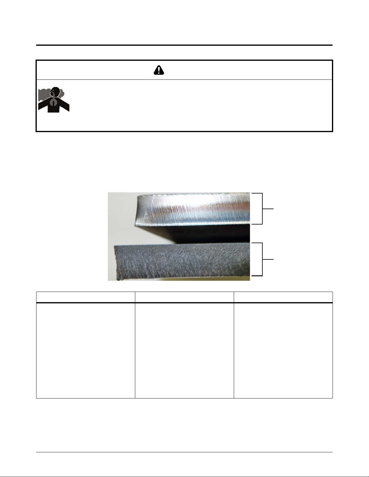
4
Cut stainless steel with F5
F5
Air
TOXIC FUMES CAN CAUSE INJURY OR DEATH
Some metals, including stainless steel, can release toxic fumes when cut. Make sure that
your work site has sufficient ventilation to make sure that the air quality level meets all local
and national standards and regulations. Refer to the Safety and Compliance Manual
(80669C) for more information.
You can use F5 gas to cut and gouge stainless steel with the Powermax65/85/105 SYNC.
Hypertherm recommends using F5 gas only for cutting stainless steel.
Plasma cutting with F5 gives smooth, shiny cuts with silver edges that are close to the original color
of the metal. F5 prevents the rough, dark finish that is a typical result of air plasma cutting.
Cut with the Machine Torch
WAR NING
F5: Advantages F5: Disadvantages F5: Similarities to air
• Smooth, shiny cut edge
• Silver cut edge, similar to the
original color of the metal (does
not leave the rough, dark surface
that air can give)
• No oxidation of the cut surface –
the cut steel keeps its corrosion
resistance
• Ability to use the same
Hypertherm cartridges as for
standard cutting and gouging
with air
Powermax65/85/105 SYNC Mechanized Cutting Guide 810480 59
• Can only use F5 gas with
stainless steel
•Slower cut speeds
• F5 gas is more expensive than
compressed air
• Slightly degraded cut quality on
bevel cuts
• Approximately the same amount
of dross (with F5 and with air,
stainless steel dross is dark in
color and can be challenging to
remove)
• Approximately the same gas
pressure requirements

Cut with the Machine Torch
4
Guidelines for cutting on water tables
SmartSYNC torches are designed to be splash resistant. They are not designed to be submerged in
water. When cutting over a water table, do the following:
Lower the water level to 76 mm (3 inches) or more below the plate.
The water level must be at least 76 mm (3 inches) below the bottom of
the plate to achieve the best cut quality.
Reduce cut speeds to the Best Quality settings specified in the Hypertherm cut charts.
Refer to the Powermax65/85/105 SYNC Cut Charts Guide (810500MU).
Keep splash-back to a minimum to protect the torch and to prevent dross on the bottom of
the plate.
Make sure that the water table is designed to safely manage the release of hydrogen gas
that can occur when cutting aluminum.
WAR NING
EXPLOSION HAZARD – CUTTING WITH ALUMINUM NEAR WATER
When water touches aluminum during plasma cutting operations, hydrogen can be
released and can explode. Do not cut aluminum alloys underwater or on a water table
unless you can prevent the accumulation of hydrogen gas. Never cut aluminum-lithium
alloys in the presence of water.
Refer to the Safety and Compliance Manual (80669C) for more information.
60 810480 Mechanized Cutting Guide Powermax65/85/105 SYNC

This section helps you to select the correct gouging cartridge and to optimize the gouge contour.
Gouging processes
Hypertherm offers the following gouging cartridges:
Gouge with the Machine Torch
Cartridge Type Purpose
Maximum Control
gouging
(green)
Maximum Removal
gouging
(green)
Plasma power supplies are shipped with a starter set of Hypertherm cartridges. For a full list of the
cutting and gouging cartridges available, refer to the Powermax65/85/105 SYNC Parts Guide
(810490).
Gouging cartridges can also be used on the hand torch. Refer to the
Powermax65/85/105 SYNC Operator Manual (810470).
For help installing the cartridge, refer to Prepare to fire the torch on page 51.
Use these cartridges for more
precise metal removal, shallow
gouge contours, and light metal
washing.
Use these cartridges for
aggressive metal removal, deep
gouge contours, and extreme
metal washing.
Powermax65/85/105 SYNC Mechanized Cutting Guide 810480 61

Gouge with the Machine Torch
5
Standoff / arc stretch
Angle of the torch
Turn of the torch
Torch center line
Speed
Output current (A)
Change the gouge contour
The width and the depth of the gouge contour are a result of the following factors. Adjust these
factors in combination to get the gouge that you want.
Figure 2 – Factors that change the gouge contour
62 810480 Mechanized Cutting Guide Powermax65/85/105 SYNC

Gouge with the Machine Torch
5
1
2
1
2
1
2
1
2
1
2
1
2
1
1
1
Output current (A) of the plasma power supply – Decrease the amperage on the front
panel to make the gouge narrower and shallower . Increase the amperage to make the
gouge wider and deeper .
Arc stretch is related to the output current (A) of the plasma power supply. The higher
the amperage, the longer that you can stretch the arc. Hypertherm recommends that you
keep amperage and arc stretch consistent.
The lowest and highest possible amperage setting relates to the plasma power supply
and the Hypertherm cartridge. Refer to the Powermax65/85/105 SYNC Operator
Manual (810470).
Angle of the torch to the workpiece – Put the torch in a more upright position to make the
gouge narrower and deeper . Tilt down the torch so that it is closer to the workpiece to
make the gouge wider and more shallow .
Turn of th e to rch – Turn the torch relative to the torch center line to make the gouge flatter
and steeper on one side .
Powermax65/85/105 SYNC Mechanized Cutting Guide 810480 63

Gouge with the Machine Torch
5
1
2
1
2
1
2
1
2
1
2
2
1
Torch-to-work standoff / arc stretch – Move the torch away from the workpiece to make
the gouge wider, shallower, and smoother on the bottom . Move the torch closer to the
workpiece to make the gouge narrower and deeper .
Arc stretch is related to the output current (A) of the plasma power supply. The higher
the amperage, the longer that you can stretch the arc. Hypertherm recommends that you
keep amperage and arc stretch consistent.
Keep at least a small distance between the torch tip and the molten metal to increase
cartridge life and prevent damage to the torch.
Speed of the torch – Increase the speed of the torch movement to make the gouge
narrower and more shallow . Decrease the speed of the torch movement to make the
gouge wider and deeper .
64 810480 Mechanized Cutting Guide Powermax65/85/105 SYNC

Common Mechanized System Problems
This section explains the following common problems and how to solve them:
Cutting system problems
Cut quality problems, such as cut angle (bevel) and dross
Gouging problems
Grounding or shielding problems
This section is a supplement to the troubleshooting information in the
Powermax65/85/105 SYNC Operator Manual (810470). When you
troubleshoot a mechanized cutting problem, use both resources.
Powermax65/85/105 SYNC Mechanized Cutting Guide 810480 65

Common Mechanized System Problems
6
Cutting system problems
Problem Solutions
The plasma arc sputters or
hisses, or you lose the
plasma arc.
• Make sure that the cartridge is installed correctly.
• Examine the cartridge. Replace it if it is worn or damaged. A higher rate of 0-30-0
faults is typical as a cartridge gets near end-of-life. Refer to Signs that a cartridge
is near end-of-life on page 48.
• Examine the gas filtration system for signs of moisture. Refer to the
Powermax65/85/105 SYNC Operator Manual (810470).
66 810480 Mechanized Cutting Guide Powermax65/85/105 SYNC

6
Problem Solutions
Common Mechanized System Problems
The plasma arc does not
transfer to the workpiece.
The torch does not
completely pierce the
workpiece, and there is
excessive sparking on the
top of the workpiece.
• Clean the workpiece surface of rust, paint, or other material that can prevent a
good metal-to-metal connection.
• Make sure that the work lead is making good contact with the cutting table or
workpiece, and is not damaged. Repair or replace it if necessary. Refer to the
Powermax65/85/105 SYNC Parts Guide (810490).
• Make sure that the cutting table is correctly grounded and is making good contact
with the workpiece.
• Decrease the cut height. Refer to the Powermax65/85/105 SYNC Cut Charts
Guide (810500MU).
• Examine the work lead for cuts or other signs of damage. Replace if necessary.
Refer to the Powermax65/85/105 SYNC Parts Guide (810490).
• Examine the cartridge. Replace it if it is worn or damaged. A higher rate of 0-30-0
faults is typical as a cartridge gets near end-of-life. Refer to Signs that a cartridge
is near end-of-life on page 48.
• Decrease your cut speed.
• Restart the plasma power supply. Does it correctly recognize the type
of cartridge installed? Does it correctly set the amperage and
operating mode to align with the cartridge? If it does not, look at the
LCD screen. Do you see the icon at right on the LCD screen? If yes,
there is possibly a plasma power supply configuration setting that you
must change. If no, there is possibly a problem with the cartridge, torch, or plasma
power supply. Refer to the Powermax65/85/105 SYNC Operator Manual
(810470).
• Increase the output current (A) on the plasma power supply.
• If the output current (A) cannot be increased, do a check to see if the thickness of
the workpiece is more than the maximum capacity for this plasma power supply.
Refer to the cutting specifications in the Powermax65/85/105 SYNC Operator
Manual (810470).
• Clean the workpiece surface of rust, paint, or other material that can prevent a
good metal-to-metal connection.
• Examine the torch lead. Make it straight if it is twisted or kinked. Replace it if it is
damaged.
• Examine the gas pressure and the gas supply hose.
• Adjust the gas flow rate. Refer to the gas supply specifications in the
Powermax65/85/105 SYNC Operator Manual (810470).
• Make sure that the cut chart parameters or the program code values are correct.
Refer to the Powermax65/85/105 SYNC Cut Charts Guide (810500MU).
Powermax65/85/105 SYNC Mechanized Cutting Guide 810480 67

Common Mechanized System Problems
6
Problem Solutions
Cartridge life is shorter
than expected.
• Do a check of the gas pressure and the gas supply hose.
• Do not start or stop cuts off of the surface of the workpiece. Starting at the edge of
the workpiece is permitted if the arc makes contact with the workpiece when
started.
• Examine the torch lead. Straighten it if it is twisted or kinked. Replace it if it is
damaged.
• Make sure that the output current, arc voltage, cut speed, and other cut settings
are correct. Refer to the Powermax65/85/105 SYNC Cut Charts Guide
(810500MU).
• Use the correct torch height for piercing. Refer to the Powermax65/85/105 SYNC
Cut Charts Guide (810500MU) for the initial pierce height.
• Make sure that the pierce delay time is correct. Refer to the
Powermax65/85/105 SYNC Cut Charts Guide (810500MU).
• Examine the gas filtration system for signs of contaminants that can interfere with
system performance.
• Examine the cut data on the Cartridge Data screen and the Power Supply Data
screen. Refer to the Powermax65/85/105 SYNC Operator Manual (810470). Also
refer to Get the most out of your cartridges on page 47.
• A faulty pilot arc IGBT can shorten cartridge life. Speak to your Hypertherm
distributor or authorized repair facility, or speak to the nearest Hypertherm office
shown in the front of this manual.
Cut quality problems
The following are problems that you can have when the appearance of a cut is unsatisfactory:
Cut angle (bevel) – The degree of angularity of the cut edge.
Dross – The molten material that solidifies on the top or bottom of the workpiece.
Each is explained in the following sections:
68 810480 Mechanized Cutting Guide Powermax65/85/105 SYNC

6
Cut angle (bevel)
1
2
3
1
2
3
Cut angle (bevel) Causes Solution
Common Mechanized System Problems
Negative bevel
More material is removed
from the bottom of the cut
than from the top.
No bevel (square cut) This is good cut quality.
Positive bevel
More material is removed
from the top of the cut than
from the bottom.
• The cutting speed is too slow.
• The torch is too low. Or, if you are
using a torch height control, arc
voltage is too low.
• The amperage is too high.
• The cartridge is worn.
• The cutting speed is too fast.
• The torch is too high. Or, if you are
using a torch height control, arc
voltage is too high.
• The amperage is too low.
• Increase the cutting speed in small
increments (125 mm/min or
5 in/min or less).
• Raise the torch in small increments
(2 mm or 1/16 in.). Or, if you are
using a torch height control,
increase the arc voltage in small
increments (5 volts or less).
• Decrease the amperage in 10 A
increments.
• Install a new cartridge.
• Decrease the cutting speed in
small increments (125 mm/min or
5 in/min or less).
• Lower the torch in small
increments (2 mm or 1/16 in.). Or,
if you are using a torch height
control, decrease the arc voltage
in small increments (5 volts or
less).
• Increase the amperage in 10 A
increments.
Irregular bevel
Positive and negative bevel
on the same workpiece.
The squarest cut angle is always on the right side with respect to the
forward motion of the torch. The left side always has some degree of
bevel. A bevel angle of more than 5 degrees shows a possible problem.
Powermax65/85/105 SYNC Mechanized Cutting Guide 810480 69
• The cartridge is severely worn.
• The torch is not aligned
perpendicular to the workpiece.
• Cut surface is concave on one
side and convex on the other side.
• Install a new cartridge.
• Use a square or digital level to
align the torch at a 90° angle to
the workpiece. Refer to Find the
cause of a cut-angle problem.

Common Mechanized System Problems
6
90°
Find the cause of a cut-angle problem
1. Make a test cut.
Use a square for the test cuts. It makes it easier to find which side is
affected by the cut-angle problem and if that side moved with the rotation
of the torch.
2. Measure the angle of each side of the test cut.
3. Turn the torch 90° in its holder.
4. Repeat steps 1 – 3.
5. If the angles are the same in both tests:
Make sure that you have removed all
mechanical causes. Refer to Configure
Controls for Mechanized Cutting on
page 19.
Do a check of the cut height (especially if
the cut angles are all positive or all
negative). Refer to the
Powermax65/85/105 SYNC Cut Charts
Guide (810500MU).
Examine the material being cut. If the
workpiece is magnetized or hardened,
then you are more likely to have cut angle
problems.
If the cut angle problem persists, speak to the manufacturer of your mechanized cutting system to
make sure that your torch height control is operating correctly.
70 810480 Mechanized Cutting Guide Powermax65/85/105 SYNC

6
Dross
Common Mechanized System Problems
Dross (slag) is molten metal that is the result of the cut process and that hardens on the bottom of
the part. There is always some amount of dross when cutting with plasma. To keep the amount and
type of dross to a minimum, adjust your system correctly for your application.
Problem Causes Solution
Too much dross (splatter) on the
top of the plate.
Low-speed dross that collects on
the bottom of the cut and is heavy
and bubbly.
• The cartridge is worn.
• The cutting speed is too fast.
• The torch is too high. Or, if you
are using a torch height
control, arc voltage is too high.
• The cutting speed is too slow.
• The torch is too low. Or, if you
are using a torch height
control, arc voltage is too low.
• The amperage is too high.
• Install a new cartridge.
• Decrease the cutting speed in
small increments
(125 mm/min or 5 in/min or
less).
• Lower the torch in small
increments (2 mm or 1/16 in.).
Or, if you are using a torch
height control, decrease the
arc voltage in small increments
(5 volts or less).
• Increase the cutting speed in
small increments
(125 mm/min or 5 in/min or
less).
•Raise the torch in small
increments (2 mm or 1/16 in.).
Or, if you are using a torch
height control, increase the
arc voltage in small increments
(5 volts or less).
• Decrease the amperage in
10 A increments.
High-speed dross near the cut that
is a thin, linear bead of solid metal.
It is welded to the bottom of the
cut and is difficult to remove.
• The cartridge is worn.
• The cutting speed is too fast.
• The torch is too high. Or, if you
are using a torch height
control, arc voltage is too high.
• The amperage is too low.
• Install a new cartridge.
• Decrease the cutting speed in
small increments
(125 mm/min or 5 in/min or
less).
• Lower the torch in small
increments (2 mm or 1/16 in.).
Or, if you are using a torch
height control, decrease the
arc voltage in small increments
(5 volts or less).
• Increase the amperage in 10 A
increments.
Powermax65/85/105 SYNC Mechanized Cutting Guide 810480 71

Common Mechanized System Problems
6
Gouging problems
When gouging, always make sure of the following:
A Hypertherm gouging cartridge is installed.
The Hypertherm cartridge is not worn or damaged. Refer to Signs that a cartridge is near
end-of-life on page 48.
The operating mode is set to Gouge mode.
When you install a Hypertherm gouging cartridge, the plasma power supply
automatically sets the operating mode to Gouge mode. There is a condition in which the
operating mode does not automatically set to Gouge mode even if a Hypertherm
gouging cartridge is used. Refer to the Powermax65/85/105 SYNC Operator Manual
(810470).
Problem Solution
The arc goes out during
gouging.
The torch tip hits the
molten metal (slag).
The gouge has too much
depth.
The gouge does not have
enough depth.
The gouge has too much
width.
• Decrease the arc stretch (standoff).
• Put the torch in a more upright position.
• Increase the arc stretch (standoff).
• Keep the torch tip pointed in the direction of the gouge that you want to make.
• Tilt the torch down so that it is closer to the workpiece.
• Increase the arc stretch (standoff).
• Increase the gouging speed.
• Decrease the output current (A).
• Refer to Change the gouge contour on page 62.
• Put the torch in a more upright position.
• Decrease the arc stretch (standoff).
• Decrease the gouging speed.
• Increase the output current (A).
• Refer to Change the gouge contour on page 62.
• Put the torch in a more upright position.
• Decrease the arc stretch (standoff).
• Increase the gouging speed.
• Decrease the output current (A).
• Refer to Change the gouge contour on page 62.
The gouge does not have
enough width.
72 810480 Mechanized Cutting Guide Powermax65/85/105 SYNC
• Tilt the torch down so that it is closer to the workpiece.
• Increase the arc stretch (standoff).
• Decrease the gouging speed.
• Increase output current (A).
• Refer to Change the gouge contour on page 62.

6
EMI grounding and shielding best practices
Types of grounding and shielding
The following types of grounding and shielding for a mechanized plasma cutting system must be
installed correctly. Refer to the diagram on page 76 for an example.
Service ground (also known as safety ground) is the grounding system that applies to the
incoming line voltage. It prevents a shock hazard to personnel from the equipment or the
cutting table. It includes the service ground coming into the plasma power supply and other
systems, such as a CNC, as well as the supplemental ground rod connected to the cutting
table.
Protective earth (PE) ground is the grounding system inside the electrical equipment. The
PE ground, which connects to the service ground, provides electrical continuity between the
equipment and the AC service.
DC power ground (also known as output current ground) is the grounding system that
completes the path of the output current from the torch back to the plasma power supply. In
this system, the positive lead from the plasma power supply must be tightly connected to
the cutting table ground bus with a correctly sized cable. Also, the slats on which the
workpiece rests must make good contact with the cutting table and the workpiece.
Common Mechanized System Problems
Electromagnetic interference (EMI) grounding and shielding is the grounding system
that limits the amount of EMI (or noise) that comes from the plasma power supply and other
equipment near the cutting system. It also limits the amount of EMI that is received by a
control (e.g., a CNC) and measurement circuits.
Grounding and shielding best practices
This section describes EMI grounding and shielding best practices specifically.
The grounding practices in this section have been used on many
installations with excellent results. Hypertherm recommends that these
practices be a routine part of the installation process. The actual methods
used to implement these practices can vary from system to system, but
must stay as consistent as possible. Due to the variation in equipment and
installations, these grounding practices cannot succeed in every case to
eliminate EMI problems. Hypertherm recommends that you refer to your
local and national electrical codes to make sure that the grounding and
shielding practices that you use satisfy the requirements for your location.
The cutting table is used for the common, or star, EMI ground point and must have threaded
studs welded to the table with a copper bus bar attached to them. A separate bus bar must
be attached to the gantry as close to each motor (if applicable) as possible. If there are
motors at each end of the gantry, install a separate EMI ground cable from the far motor to
the gantry bus bar. The gantry bus bar must have a separate, heavy EMI ground cable to the
table bus bar. Make the routing of each of the EMI ground cables for the torch lifter, if
applicable, separate to the table ground bus.
Insufficient grounding exposes operators to dangerous voltages. Insufficient grounding also
increases the risk of equipment failure and unnecessary downtime. Ideally a ground should
be zero ohms resistance, but Hypertherm’s field experience shows that less than 1 ohm
Powermax65/85/105 SYNC Mechanized Cutting Guide 810480 73

Common Mechanized System Problems
6
resistance is satisfactory for most applications. Hypertherm recommends that you refer to
your local and national electrical codes to make sure that the grounding and shielding
practices that you use satisfy the requirements for your location.
A ground rod (a PE ground) that meets all applicable local and national electric codes must
be installed within 6 m (20 ft) of the cutting table. The PE ground must connect to the
cutting table ground bus bar. Speak to an electrician in your location to make sure that your
grounding meets all local and national electric codes.
All hardware used in the ground system must be brass or copper. While you can use steel
studs welded to the cutting table for attaching the ground bus, no other aluminum or steel
hardware can be used in the ground system.
AC power, PE, and service grounds must connect to all equipment according to local and
national codes.
Each Hypertherm component, as well as the CNC or other components or enclosures, must
have a separate ground cable to the common (star) ground on the table.
The torch holder and the torch breakaway mechanism – the part attached to the lifter, not
the part attached to the torch – must connect to the stationary part of the lifter with copper
braid. A separate cable must go from the lifter to the gantry ground bus bar.
If the gantry operates on rails that are not welded to the table, then each rail must connect
with a ground cable from the end of the rail to the table. The rail ground cables connect
directly to the table. It is not necessary to connect the rail ground cables to the table ground
bus bar.
The torch lead and work lead can go parallel to other wires or cables only if they are
separated by at least 150 mm (6 inches). If possible, put power and signal cables in
separate cable tracks. If it is not possible to keep at least a 150 mm (6 inch) separation
between cables, then add shielding to decrease the noise interaction. If cables must cross
paths, make sure that the groups intersect at right angles.
You can attach the work lead from the plasma power supply to the cutting table or to the
workpiece you are cutting. Make sure that the work lead makes good metal-to-metal contact
with the cutting table or workpiece. Remove rust, dirt, paint, coatings, and other debris so
that the work lead makes sufficient contact with the cutting table or workpiece.
The metal braided shield on the torch lead must connect tightly to the torch. Hypertherm
recommends that it be electrically insulated from metal and from contact with the floor or
building. Put the torch lead in a plastic cable tray or track, or cover the torch lead with a
plastic or leather sheath.
If you are installing an external voltage divider PCB, attach it as closely as possible to where
the arc voltage is sampled. If a Hypertherm voltage divider PCB is used, you must supply
galvanic isolation to prevent ground loops. The processed signal must go through a twisted
shielded cable. Use a cable with a braided shield, not a foil shield. A shield with a braid over
foil is best. Connect the shield to the chassis of the plasma power supply and leave it
unconnected at the other end.
Insulation on an electrical cable does not prevent electromagnetic
interference (EMI). Shielding for electrical wires, including insulated
cables, is necessary to prevent noise-related problems.
74 810480 Mechanized Cutting Guide Powermax65/85/105 SYNC

Common Mechanized System Problems
6
All other signals (analog, digital, serial, and encoder) must go through twisted pairs inside a
shielded cable. Connectors on these cables must have a metal housing. The shield, not the
drain, must connect to the metal housing of the connector at each end of the cable. Never
put the shield or the drain through the connector on the pins.
Use correct shield grounding techniques. Connect a braided shield over its entire
circumference by using grounding clamps or EMC cable glands. A 360-degree shield
connection is much better than other connection methods. The quality of the shield bond
increases with the clamped surface area. Install ferrite sleeves on long-length data cables.
Ferrite sleeves decrease common mode noise currents without affecting the differential
signal currents. If necessary, put multiple turns through the ferrite.
Powermax65/85/105 SYNC Mechanized Cutting Guide 810480 75

Common Mechanized System Problems
6
2
5
3
4
7
8
9
1
6
Chassis and EMI ground
Service ground
PE earth ground
1 Cutting table
2 Gantry
3 Plasma system
4 Table ground bus bar
5 Gantry ground bus bar
6 Torch height control lifter
7 CNC controller
8 Torch height control module
9 DC power ground (work)
Example grounding diagram
76 810480 Mechanized Cutting Guide Powermax65/85/105 SYNC
This example is based on practices in North America. Other regions can
have different local or national electrical codes. Hypertherm recommends
that you consult your local and national electrical codes to make sure that
the grounding and shielding practices that you use satisfy the
requirements for your location.
 Loading...