

Page 1

FASTLaser®Cutting Heads
LH2125/LH2100
®
Instruction Manual
810250 – Revision 1
Page 2

LH2125/LH2100
FASTLaser Cutting Heads
Instruction Manual
Part Number – 810250
Revision 1 – January, 2008
© Copyright 2008 Hypertherm, Inc.
All Rights Reserved
Hypertherm and FAST Laser are trademarks of Hypertherm, Inc.
and may be registered in the United States and/or other countries
Hypertherm, Inc.
Hanover, NH USA
www.hypertherm.com
Page 3

Hypertherm, Inc.
Etna Road, P.O. Box 5010
Hanover, NH 03755 USA
603-643-3441 Tel (Main Office)
603-643-5352 Fax (All Departments)
info@hypertherm.com (Main Office Email)
800-643-9878 Tel (Technical Service)
technical.service@hypertherm.com (Technical Service Email)
800-737-2978 Tel (Customer Service)
customer.service@hypertherm.com (Customer Service Email)
Hypertherm Automation
5 Technology Drive, Suite 300
West Lebanon, NH 03784 USA
603-298-7970 Tel
603-298-7977 Fax
Hypertherm Plasmatechnik GmbH
Technologiepark Hanau
Rodenbacher Chaussee 6
D-63457 Hanau-Wolfgang, Deutschland
49 6181 58 2100 Tel
49 6181 58 2134 Fax
49 6181 58 2123 (Technical Service)
Hypertherm (S) Pte Ltd.
No. 19 Kaki Bukit Road 2
K.B. Warehouse Complex
Singapore 417847, Republic of Singapore
65 6 841 2489 Tel
65 6 841 2490 Fax
65 6 841 2489 (Technical Service)
Hypertherm (Shanghai) Trading Co., Ltd.
Unit 1308-09, Careri Building
432 West Huai Hai Road
Shanghai, 200052
PR China
86-21 5258 3330/1 Tel
86-21 5258 3332 Fax
France (Representative office)
15 Impasse des Rosiers
95610 Eragny, France
00 800 3324 9737 Tel
00 800 4973 7329 Fax
Hypertherm S.r.l.
Via Torino 2
20123 Milano, Italia
39 02 725 46 312 Tel
39 02 725 46 400 Fax
39 02 725 46 314 (Technical Service)
Hypertherm Europe B.V.
Vaartveld 9
4704 SE Roosendaal, Nederland
31 165 596907 Tel
31 165 596901 Fax
31 165 596908 Tel (Marketing)
31 165 596900 Tel (Technical Service)
00 800 49 73 7843 Tel (Technical Service)
Hypertherm Japan Ltd.
801 Samty Will Building
2-40 Miyahara 1-Chome,
Yodogawa-ku, Osaka
532-0003, Japan
81 6 6170 2020 Tel
81 6 6170 2015 Fax
HYPERTHERM BRASIL LTDA.
Avenida Doutor Renato de
Andrade Maia 350
Parque Renato Maia
CEP 07114-000
Guarulhos, SP Brasil
55 11 6409 2636 Tel
55 11 6408 0462 Fax
Hypertherm
Branch of Hypertherm, UK, UC
PO Box 244
Wigan, Lancashire, England WN8 7WU
00 800 3324 9737 Tel
00 800 4973 7329 Fax
00 800 4973 7843 (Technical Service)
1/19/07
Page 4

ELECTROMAGNETIC COMPATIBILITY (EMC)
Hypertherm i
6-07
EMC Introduction
Hypertherm’s CE-marked equipment is built in compliance
with standard EN60974-10. The equipment should be
installed and used in accordance with the information
below to achieve electromagnetic compatibility.
The limits required by EN60974-10 may not be adequate
to completely eliminate interference when the affected
equipment is in close proximity or has a high degree of
sensitivity. In such cases it may be necessary to use other
measures to further reduce interference.
This cutting equipment is designed for use only in an
industrial environment.
Installation and use
The user is responsible for installing and using the plasma
equipment according to the manufacturer’s instructions.
If electromagnetic disturbances are detected then it shall
be the responsibility of the user to resolve the situation
with the technical assistance of the manufacturer. In some
cases this remedial action may be as simple as earthing
the cutting circuit, see Earthing of Workpiece. In other
cases it could involve constructing an electromagnetic
screen enclosing the power source and the work
complete with associated input filters. In all cases
electromagnetic disturbances must be reduced to the
point where they are no longer troublesome.
Assessment of area
Before installing the equipment the user shall make an
assessment of potential electromagnetic problems in the
surrounding area. The following shall be taken into
account:
a. Other supply cables, control cables, signalling and
telephone cables; above, below and adjacent to the
cutting equipment.
b. Radio and television transmitters and receivers.
c. Computer and other control equipment.
d. Safety critical equipment, for example guarding of
industrial equipment.
e. Health of the people around, for example the use of
pacemakers and hearing aids.
f. Equipment used for calibration or measurement.
g. Immunity of other equipment in the environment. User
shall ensure that other equipment being used in the
environment is compatible. This may require additional
protection measures.
h. Time of day that cutting or other activities are to be
carried out.
The size of the surrounding area to be considered will
depend on the structure of the building and other
activities that are taking place. The surrounding area may
extend beyond the boundaries of the premises.
Methods of reducing emissions
Mains supply
Cutting equipment must be connected to the mains
supply according to the manufacturer’s recommendations.
If interference occurs, it may be necessary to take
additional precautions such as filtering of the mains supply.
Consideration should be given to shielding the supply
cable of permanently installed cutting equipment, in
metallic conduit or equivalent. Shielding should be
electrically continuous throughout its length. The shielding
should be connected to the cutting mains supply so that
good electrical contact is maintained between the conduit
and the cutting power source enclosure.
Maintenance of cutting equipment
The cutting equipment must be routinely maintained
according to the manufacturer’s recommendations. All
access and service doors and covers should be closed
and properly fastened when the cutting equipment is in
operation. The cutting equipment should not be modified
in any way except for those changes and adjustments
covered in the manufacturer’s instructions. In particular,
the spark gaps of arc striking and stabilizing devices
should be adjusted and maintained according to the
manufacturer’s recommendations.
Cutting cables
The cutting cables should be kept as short as possible
and should be positioned close together, running at or
close to the floor level.
Equipotential bonding
Bonding of all metallic components in the cutting
installation and adjacent to it should be considered.
However, metallic components bonded to the workpiece
will increase the risk that the operator could receive a
shock by touching these metallic components and the
electrode (nozzle for laser heads) at the same time.
The operator should be insulated from all such bonded
metallic components.
Page 5

0
ELECTROMAGNETIC COMPATIBILITY (EMC)
ii Hypertherm
8-06
Earthing of workpiece
Where the workpiece is not bonded to earth for electrical
safety, nor connected to earth because of its size and
position, for example, ship’s hull or building steelwork, a
connection bonding the workpiece to earth may reduce
emissions in some, but not all instances. Care should be
taken to prevent the earthing of the workpiece increasing
the risk of injury to users, or damage to other electrical
equipment. Where necessary, the connection of the
workpiece to earth should be made by a direct
connection to the workpiece, but in some countries where
direct connection is not permitted, the bonding should be
achieved by suitable capacitances selected according to
national regulations.
Note: the cutting circuit may or may not be earthed for
safety reasons. Changing the earthing arrangements
should only be authorized by a person who is competent
to assess whether the changes will increase the risk of
injury, for example, by allowing parallel cutting current
return paths which may damage the earth circuits of other
equipment. Further guidance is given in IEC/TS 62081
Arc Welding Equipment Installation and Use.
Screening and shielding
Selective screening and shielding of other cables
and equipment in the surrounding area may alleviate
problems of interference. Screening of the entire
plasma cutting installation may be considered for
special applications.
Page 6

0
WARRANTY
Hypertherm iii
6-07
Attention
Genuine Hypertherm parts are the factory-recommended
replacement parts for your Hypertherm system. Any
damage caused by the use of other than genuine
Hypertherm parts may not be covered by the
Hypertherm warranty.
You are responsible for the safe use of the Product.
Hypertherm does not and cannot make any guarantee
or warranty regarding the safe use of the Product in
your environment.
General
Hypertherm, Inc. warrants that its Products shall be free
from defects in materials and workmanship, if Hypertherm
is notified of a defect (i) with respect to the power supply
within a period of two (2) years from the date of its delivery
to you, with the exception of Powermax Series power
supplies, which shall be within a period of three (3) years
from the date of delivery to you, and (ii) with respect to the
torch and leads within a period of one (1) year from its date
of delivery to you, and with respect to torch lifter
assemblies within a period of one (1) year from its date of
delivery to you, and with respect to laser heads within a
period of one (1) year from its date of delivery to you. This
warranty shall not apply to any Product which has been
incorrectly installed, modified, or otherwise damaged.
Hypertherm, at its sole option, shall repair, replace, or
adjust, free of charge, any defective Products covered by
this warranty which shall be returned with Hypertherm’s
prior authorization (which shall not be unreasonably
withheld), properly packed, to Hypertherm’s place of
business in Hanover, New Hampshire, or to an authorized
Hypertherm repair facility, all costs, insurance and freight
prepaid. Hypertherm shall not be liable for any repairs,
replacement, or adjustments of Products covered by this
warranty, except those made pursuant to this paragraph or
with Hypertherm’s prior written consent. The warranty
above is exclusive and is in lieu of all other
warranties, express, implied, statutory, or otherwise
with respect to the Products or as to the results
which may be obtained therefrom, and all implied
warranties or conditions of quality or of
merchantability or fitness for a particular purpose or
against infringement. The foregoing shall constitute
the sole and exclusive remedy for any breach by
Hypertherm of its warranty. Distributors/OEMs may
offer different or additional warranties, but Distributors/
OEMs are not authorized to give any additional warranty
protection to you or make any representation to you
purporting to be binding upon Hypertherm.
Certification test marks
Certified products are identified by one or more
certification test marks from accredited testing laboratories.
The certification test marks are located on or near the data
plate. Each certification test mark means that the product
and its safety-critical components conform to the relevant
national safety standards as reviewed by that testing
laboratory. Hypertherm places a certification test mark on
its products only after that product is manufactured with
safety-critical components that have been authorized by the
accredited testing laboratory.
Once the product has left the Hypertherm factory, the
certification test marks are invalidated if any of the following
occurs:
• The product is significantly modified in a manner that
creates a hazard or non-conformance.
• Safety-critical components are replaced with
unauthorized spare parts.
• Any unauthorized assembly or accessory that uses or
generates a hazardous voltage is added.
• There is any tampering with a safety circuit or other
feature that is designed into the product as part of the
certification.
CE marking constitutes a manufacturer’s declaration of
conformity to applicable European directives and
standards. Only those versions of Hypertherm products
with a CE Marking located on or near the data plate have
been tested for compliance with the European Low Voltage
Directive and the European EMC Directive. EMC filters
needed to comply with the European EMC Directive are
incorporated within versions of the power supply with a
CE Marking.
Patent indemnity
Except only in cases of products not manufactured by
Hypertherm or manufactured by a person other than
Hypertherm not in strict conformity with Hypertherm’s
specifications and in cases of designs, processes,
formulae, or combinations not developed or purported to
be developed by Hypertherm, Hypertherm will defend or
settle, at its own expense, any suit or proceeding brought
against you alleging that the use of the Hypertherm
product, alone and not in combination with any other
product not supplied by Hypertherm, infringes any patent of
any third party. You shall notify Hypertherm promptly upon
learning of any action or threatened action in connection
with any such alleged infringement, and Hypertherm’s
Page 7

0
WARRANTY
iv Hypertherm
6-07
obligation to indemnify shall be conditioned upon
Hypertherm’s sole control of, and the indemnified party’s
cooperation and assistance in, the defense of the claim.
Limitation of liability
In no event shall Hypertherm be liable to any person
or entity for any incidental, consequential, indirect,
or punitive damages (including but not limited to
lost profits) regardless of whether such liability is
based on breach of contract, tort, strict liability,
breach of warranties, failure of essential purpose or
otherwise and even if advised of the possibility of
such damages.
Liability cap
In no event shall Hypertherm’s liability, whether such
liability is based on breach of contract, tort, strict
liability, breach of warranties, failure of essential
purpose or otherwise, for any claim action suit or
proceeding arising out of or relating to the use of
the Products exceed in the aggregate the amount
paid for the Products that gave rise to such claim.
Insurance
At all times you will have and maintain insurance in such
quantities and types, and with coverage sufficient and
appropriate to defend and to hold Hypertherm harmless
in the event of any cause of action arising from the use of
the Products.
National and Local codes
National and Local codes governing plumbing and
electrical installation shall take precedent over any
instructions contained in this manual. In no event shall
Hypertherm be liable for injury to persons or property
damage by reason of any code violation or poor work
practices.
Transfer of rights
You may transfer any remaining rights you may have
hereunder only in connection with the sale of all or
substantially all of your assets or capital stock to a
successor in interest who agrees to be bound by all of the
terms and conditions of this Warranty.
Proper disposal of Hypertherm
products
Hypertherm plasma cutting systems, like all electronic
products, may contain materials or components, such as
printed circuit boards, that cannot be discarded with
ordinary waste. It is your responsibility to dispose of any
Hypertherm product or component part in an
environmentally acceptable manner according to national
and local codes.
• In the United States, check all federal, state, and local
laws.
• In the European Union, check the EU directives, national,
and local laws. For more information, visit
www.hypertherm.com/weee.
• In other countries, check national and local laws.
Page 8

TABLE OF CONTENTS
1
LH2125/LH2100 Laser Head Instruction Manual v
Electromagnetic Compatibility (EMC) ...................................................................................................................................i
Warranty.......................................................................................................................................................................................iii
Section 1 Safety...................................................................................................................................................................1-1
Recognize safety information...................................................................................................................................................................1-2
Follow safety instructions .........................................................................................................................................................................1-2
Cutting can cause fire or explosion........................................................................................................................................................1-2
Radiation hazard.........................................................................................................................................................................................1-2
Electric shock can kill................................................................................................................................................................................1-3
Cutting can produce toxic fumes............................................................................................................................................................1-3
A laser can cause injury and burns ........................................................................................................................................................1-3
A laser can burn eyes and skin ...............................................................................................................................................................1-4
Grounding safety........................................................................................................................................................................................1-4
Pacemaker and hearing aid operation...................................................................................................................................................1-4
Section 2 Specifications....................................................................................................................................................2-1
Cutting head................................................................................................................................................................................................2-2
Requirements ..............................................................................................................................................................................................2-2
Electrical ...........................................................................................................................................................................................2-2
Purge gas...........................................................................................................................................................................................2-2
Cutting gas........................................................................................................................................................................................2-2
Coolant requirements......................................................................................................................................................................2-2
Section 3 Installation..........................................................................................................................................................3-1
Mounting dimensions ................................................................................................................................................................................3-2
Right side connections .............................................................................................................................................................................3-6
Single channel interface box installation ..............................................................................................................................................3-7
Controller cable connector information.......................................................................................................................................3-7
Connect cables ................................................................................................................................................................................3-7
Capacitive height sensor (CHS) interface box installation...............................................................................................................3-8
Controller cable connector information ......................................................................................................................................3-8
Connect cables ................................................................................................................................................................................3-8
Left side connections ................................................................................................................................................................................3-9
Lens travel..........................................................................................................................................................................................3-9
Color codes.......................................................................................................................................................................................3-9
Lens installation........................................................................................................................................................................................3-10
Alignment guides .....................................................................................................................................................................................3-11
Crosshair assembly.......................................................................................................................................................................3-11
Aperture assembly ........................................................................................................................................................................3-12
Section 4 Operation............................................................................................................................................................4-1
Operation safety .........................................................................................................................................................................................4-2
FAST Laser nozzles ....................................................................................................................................................................................4-3
Principles of operation ...................................................................................................................................................................4-3
FAST nozzle installation ..................................................................................................................................................................4-3
Inspect the baffle..............................................................................................................................................................................4-3
Page 9

TABLE OF CONTENTS
1
vi LH2125/LH2100 Laser Head Instruction Manual
Piercing.........................................................................................................................................................................................................4-4
Mild steel............................................................................................................................................................................................4-4
Stainless steel and aluminum........................................................................................................................................................4-4
Single channel interface adjustments....................................................................................................................................................4-5
Cut-error monitor..............................................................................................................................................................................4-5
Precision adjustments.....................................................................................................................................................................4-5
Capacitive height sensing ........................................................................................................................................................................4-7
Introduction........................................................................................................................................................................................4-7
Operation...........................................................................................................................................................................................4-8
Adjustment.........................................................................................................................................................................................4-8
Cut charts..................................................................................................................................................................................................4-10
Mild steel .........................................................................................................................................................................................4-10
Stainless steel................................................................................................................................................................................4-10
Focal position locations..........................................................................................................................................................................4-11
Maintenance..............................................................................................................................................................................................4-12
Drive mechanism ...........................................................................................................................................................................4-12
Inspect nozzle.................................................................................................................................................................................4-12
Inspect lens.....................................................................................................................................................................................4-12
Clean lens .......................................................................................................................................................................................4-13
Lens mounting – standard and pre-mounted options ..................................................................................................................4-14
Standard..........................................................................................................................................................................................4-14
Premounted ....................................................................................................................................................................................4-15
Lens centering................................................................................................................................................................................4-15
Troubleshooting (O2 cutting).................................................................................................................................................................4-16
Troubleshooting (N2 cutting) .................................................................................................................................................................4-18
Section 5 Parts List .............................................................................................................................................................5-1
Outside view................................................................................................................................................................................................5-2
Consumables ..............................................................................................................................................................................................5-3
Parts and accessories kits .......................................................................................................................................................................5-4
Single channel optics and lens adjustment screws ...........................................................................................................................5-5
Capacitive height sensor..........................................................................................................................................................................5-6
Lenses...........................................................................................................................................................................................................5-7
Apperture, crosshair and receiver assemblies.....................................................................................................................................5-8
Motor and timing belt.................................................................................................................................................................................5-9
Appendix A ZnSe LENS SAFETY DATA .........................................................................................................................a-1
Section I product identification.........................................................................................................................................................a-2
Section 2 Hazardous Ingredients.....................................................................................................................................................a-2
Section 3 Physical data......................................................................................................................................................................a-2
Section 4 Fire and explosion hazard data ......................................................................................................................................a-2
Section 5 Health hazard data............................................................................................................................................................a-3
Section 6 Reactivity data....................................................................................................................................................................a-4
Section 7 Disposal information.........................................................................................................................................................a-4
Section 8 Special Protection information.......................................................................................................................................a-4
Section 9 Special precautions..........................................................................................................................................................a-5
Page 10

Hypertherm 1-1
10/03
Section 1
SAFETY
In this section:
Recognize safety information...................................................................................................................................................................1-2
Follow safety instructions .........................................................................................................................................................................1-2
Cutting can cause fire or explosion........................................................................................................................................................1-2
Radiation hazard.........................................................................................................................................................................................1-2
Electric shock can kill................................................................................................................................................................................1-3
Cutting can produce toxic fumes............................................................................................................................................................1-3
A laser can cause injury and burns ........................................................................................................................................................1-3
A laser can burn eyes and skin ...............................................................................................................................................................1-4
Grounding safety........................................................................................................................................................................................1-4
Pacemaker and hearing aid operation...................................................................................................................................................1-4
Page 11
SAFETY
10/03
1-2 Hypertherm
RECOGNIZE SAFETY INFORMATION
The symbols shown in this section are used
to identify potential hazards. When you see a safety symbol
in this manual or on your machine, understand the potential
for personal injury, and follow the related instructions to
avoid the hazard.
FOLLOW SAFETY INSTRUCTIONS
Read carefully all safety messages in this manual and safety
labels on your machine.
• Keep the safety labels on your machine in good
condition. Replace missing or damaged labels
immediately.
• Learn how to operate the machine and how to use
the controls properly. Do not let anyone operate it without
instruction.
• Keep your machine in proper working condition.
Unauthorized modifications to the machine may affect
safety and machine service life.
DANGER WARNING CAUTION
A signal word DANGER or WARNING is used with a
safety symbol. DANGER identifies the most serious
hazards.
• DANGER and WARNING safety labels are located
on your machine near specific hazards.
• WARNING safety messages precede related instruc tions in this manual that may result in injury or death if
not followed correctly.
• CAUTION safety messages precede related
instructions in this manual that may result in damage
to equipment if not followed correctly.
Fire Prevention
• Be sure the area is safe before doing any cutting. Keep a fire extinguisher nearby.
• Remove all flammables within 35 feet (10 m) of the cutting area.
• Quench hot metal or allow it to cool before handling or before letting it touch combustible materials.
• Never cut containers with potentially flammable materials inside – they must be emptied and properly cleaned first.
• Ventilate potentially flammable atmospheres before cutting.
Explosion Prevention
• Do not use the laser system if explosive dust or vapors may be present.
• Do not cut pressurized cylinders, pipes, or any closed container.
• Do not cut containers that have held combustible materials.
CUTTING CAN CAUSE FIRE OR EXPLOSION
• Visible or invisible radiation (class IV) can be present when the laser head door is open.
• Avoid eye and skin exposure to direct and scattered radiation.
• Never look into the laser beam.
RADIATION HAZARD
Page 12
SAFETY
10/03
Hypertherm 1-3
The laser beam will cut quickly through gloves and skin.
• Keep away from the nozzle tip.
• Do not hold metal near the cutting path.
• Never point the laser toward yourself or others.
A LASER CAN CAUSE INJURY AND BURNS
Electric Shock Prevention
• Never touch the laser head, while in operation.
• Install and ground this equipment according to the instruction manual and in accordance with national or
local codes.
• Inspect the input power cord frequently for damage or cracking of the cover. Replace a damaged power cord
immediately. Bare wiring can kill.
• Before checking, cleaning or changing parts, disconnect the main power or unplug the power supply.
• When making input connections, attach proper grounding conductor first.
ELECTRIC SHOCK CAN KILL
Cutting can produce toxic fumes and gases that deplete
oxygen and cause injury or death.
• Keep the cutting area well ventilated or use an
approved air-supplied respirator.
• Do not cut in locations near degreasing, cleaning or
spraying operations. The vapors from certain
chlorinated solvents decompose to form phosgene
gas when exposed to ultraviolet radiation.
• Do not cut metal coated or containing toxic materi als,
such as zinc (galvanized), lead, cadmium or beryllium,
unless the area is well ventilated and the operator
CUTTING CAN PRODUCE TOXIC FUMES
wears an air-supplied respirator. The coatings and any
metals containing these elements can produce toxic
fumes when cut.
• Never cut containers with potentially toxic materials
inside – they must be emptied and properly
cleaned first.
• This product, when used for welding or cutting,
produces fumes or gases which contain chemicals
known to the State of California to cause birth defects
and, in some cases, cancer.
Page 13
SAFETY
5/04
1-4 Hypertherm
Eye Protection Lasers produce intense visible and
invisible (ultraviolet and infrared) rays that can burn eyes
and skin.
• Use eye protection in accordance with applicable
national or local codes.
• Wear eye protection (safety glasses or goggles with
side shields) with appropriate lens shading to protect
your eyes from ultraviolet and infrared rays.
• Reference laser system manufacturer and standard
BS EN 207:1999 for proper eye protection level.
A LASER CAN BURN EYES AND SKIN
Skin Protection Wear protective clothing to protect
against burns caused by ultraviolet light, sparks and hot
metal.
• Gauntlet gloves, safety shoes and hat.
• Flame-retardant clothing to cover all exposed areas.
• Cuffless trousers to prevent entry of sparks and slag.
• Remove any combustibles, such as a butane lighter or
matches, from your pockets before cutting.
Input Power
• If installation of the laser head involves connecting the power cord to the power supply, be sure to connect the
power cord ground wire properly.
• Tighten all electrical connections to avoid excessive heating.
• Follow system recommendations for grounding the workpiece.
GROUNDING SAFETY
Pacemaker and hearing aid operation can be affected by magnetic fields from high currents.
Pacemaker and hearing aid wearers should consult a doctor before going near any cutting equipment.
PACEMAKER AND HEARING AID OPERATION
DANGER
Never put fingers or hands between the lens assembly and the laser head enclosure. Moving parts can cause
severe crush injuries.
Page 14

LH2125/LH2100 Laser Head Instruction Manual 2-1
0
Section 2
SPECIFICATIONS
In this section:
Cutting head................................................................................................................................................................................................2-2
Requirements ..............................................................................................................................................................................................2-2
Electrical ...........................................................................................................................................................................................2-2
Purge gas...........................................................................................................................................................................................2-2
Cutting gas........................................................................................................................................................................................2-2
Coolant requirements......................................................................................................................................................................2-2
Page 15

1
SPECIFICATIONS
2-2 LH2125/LH2100 Laser Head Instruction Manual
Cutting head
This manual provides the information needed to install, operate, and maintain the LH2125 and LH2100 laser cutting
heads. The LH2125/2100 is designed to process material with a CO2laser cutting system. Lens position is controlled
by a servo motor for precise and repeatable location of the focal position, relative to the cutting nozzle. The LH2100
accepts 2" (50.8 mm) diameter optics with focal lengths of 7.5" and 10" (190.5 mm and 254 mm).The LH2125 accepts
2" (50.8 mm) diameter optics with focal lengths of 7.5", 10" and 12.5" (190.5 mm, 254 mm and 317.5 mm).
Requirements
Electrical:
Motor ..................................................................................................................System dependent
Encoder..............................................................................................................System dependent
Sensor................................................................................................................9 – 36 VDC, 2 Watts
Capacitive interface.........................................................................................9 – 36 VDC, 5 Watts
Purge gas: air or nitrogen
Gas quality ........................................................................................................Clean, dry and oil-free
Flow rate ............................................................................................................2 liters/minute
The customer must provide a regulated gas supply capable of delivering at a pressure of 1.4 bar (20 psig) to the laser
head.
Cutting gas: air, oxygen, nitrogen
Maximum system pressure ............................................................................27.5 bar (400 psi)*
Coolant requirements:
Coolant type......................................................................................................Water
Water purity.......................................................................................................200 kΩ – cm
Flow rate ............................................................................................................9 liters/hour (2.4 gallons/hour)
Pressure ............................................................................................................4.8 bar (70 psi) maximum
Note: Use purified water as coolant in order to prevent corrosion in the coolant system. The hardness
of the water should be between 0.2 and 8.5 ppm. If using a conductivity meter to measure
water purity, the recommended level is between 0.5 and 5 µ Siemens/cm at 25° C (77° F).
*Maximum pressure is determined by the individual lens used. Check with the lens manufacturer for pressure rating.
Hypertherm lenses are rated for 20.7 bar (300 psi).
Page 16

LH2125/LH2100 Laser Head Instruction Manual 3-1
1
Section 3
INSTALLATION
In this section:
Mounting dimensions ................................................................................................................................................................................3-2
Right side connections .............................................................................................................................................................................3-6
Single-channel interface box installation ..............................................................................................................................................3-7
Controller cable connector information.......................................................................................................................................3-7
Connect cables ................................................................................................................................................................................3-7
Capacitive height-sensor (CHS) interface box installation...............................................................................................................3-8
Controller cable connector information ......................................................................................................................................3-8
Connect cables ................................................................................................................................................................................3-8
Left side connections ................................................................................................................................................................................3-9
Lens travel..........................................................................................................................................................................................3-9
Color codes.......................................................................................................................................................................................3-9
Lens installation........................................................................................................................................................................................3-10
Alignment guides .....................................................................................................................................................................................3-11
Cross-hair assembly .....................................................................................................................................................................3-11
Aperture assembly ........................................................................................................................................................................3-12
Page 17
0
INSTALLATION
3-2 LH2125/LH2100 Laser Head Instruction Manual
9.1 Kgs
20 Lbs
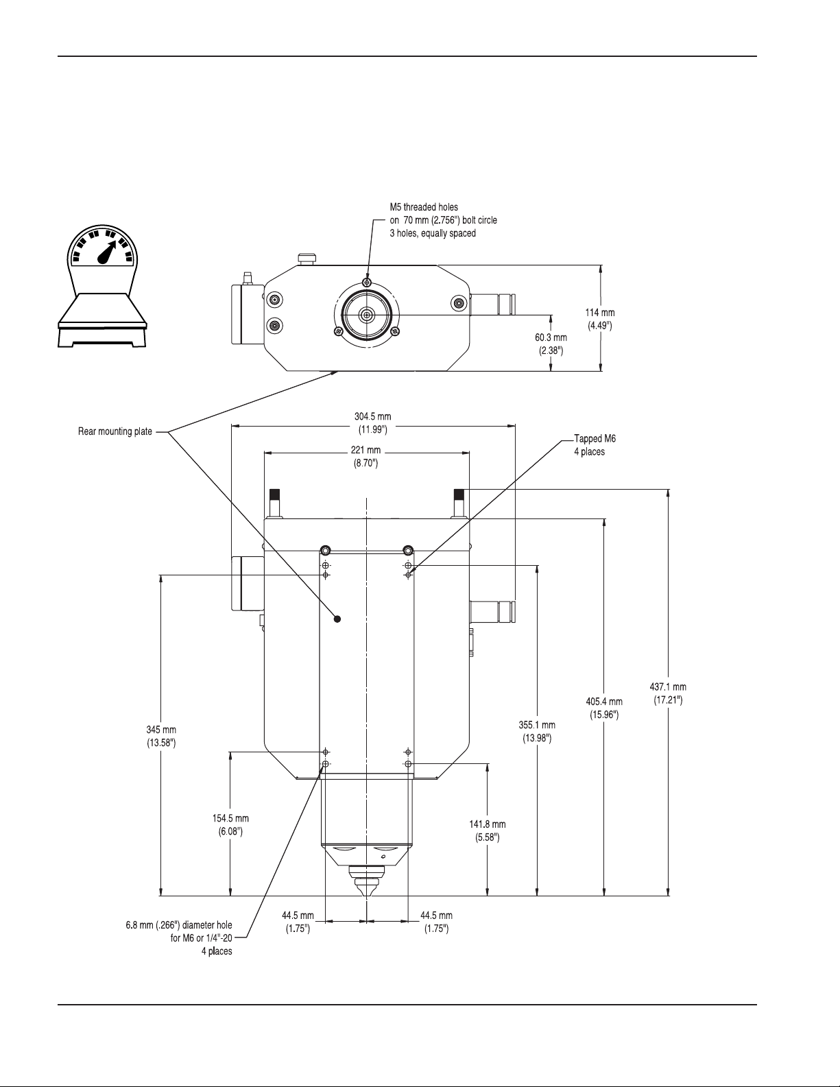
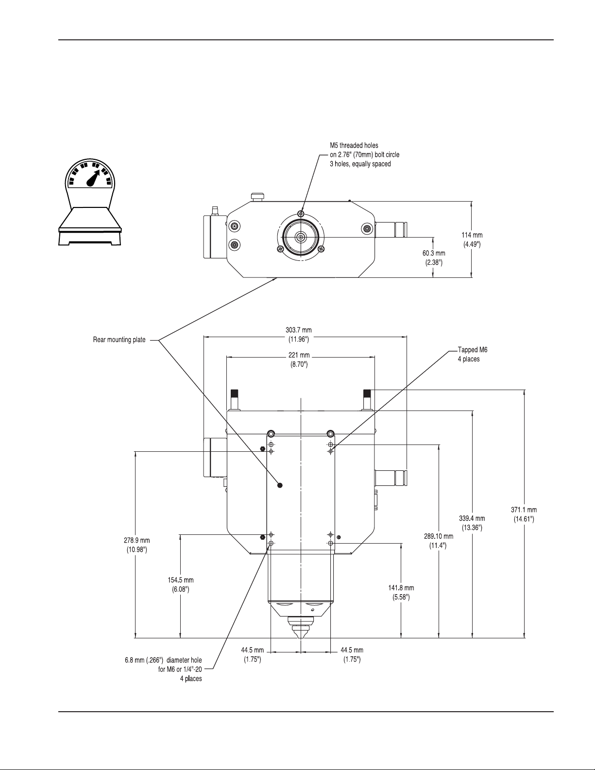
Mounting dimensions
Note: Customer is responsible for breakaway collision protection.
LH2125
Page 18
LH2100
7.7 Kgs
17 Lbs
0
INSTALLATION
LH2125/LH2100 Laser Head Instruction Manual 3-3
Page 19

1
INSTALLATION
3-4 LH2125/LH2100 Laser Head Instruction Manual
0.54 Kgs
1.2 Lbs
Capacitive height sensor – interface box
Page 20

1
INSTALLATION
LH2125/LH2100 Laser Head Instruction Manual 3-5
0.64 Kgs
1.4 Lbs
single-channel interface box
Page 21

1
INSTALLATION
3-6 LH2125/LH2100 Laser Head Instruction Manual
Right side connections
single-channel interface (SC):
box and cable
Capacitive height-sensing
amplifier
Coolant water OUT:
1/8" NPT, internal thread
Coolant water IN:
1/8" NPT, internal thread
Anti-spatter IN:
1/8" NPT, external thread
Pressure port:
1/8" NPT, external thread
Capacitive height sensing interface (CHS):
box and cable
Page 22

single-channel interface box installation
The single-channel interface box provides 3 independent optically isolated outputs. Outputs can be used by the
controller to detect piercing and cutting operations.
Controller cable connector information (9 pin D-Sub)
J1 pin-outs (Output To Controller)
Output Circuit
+ Output
+ Output
MOC8050
If = 2mA
Connect cables
Controller cable – 9 pin cable to controller
Sensor cable – interface box to laser head
Pin Wire
Number Color Description
1 Red Voltage in+ (9-36 VDC, 2 watts maximum)
2 Black Voltage in3 White Cut error +
4 Green Cut error 5 Blue Continuous wave pierce complete +
6 Brown Continuous wave Pierce complete 7 Orange Pulsed pierce complete +
8 Yellow Pulsed pierce complete 9 Shield Electromagnetic protection (earth ground)
1
INSTALLATION
LH2125/LH2100 Laser Head Instruction Manual 3-7
Note: Nominal voltage drop across output (+/-) is 1.2 volts. Current must be limited by input
resistance.
Page 23

Connect cables
Interface box (CHS) 15-pin cable to controller
Amplifier module to interface box (CHS)
1
INSTALLATION
3-8 LH2125/LH2100 Laser Head Instruction Manual
Capacitive height sensor (CHS) interface box installation
The amplifier module will be mounted to the laser head if the capacitive height sensing option was ordered. Choose a
suitable location for the CHS interface box.
Controller cable connector information (15 pin D-Sub)
Pin-outs (Output To Controller)
Note: Outputs are dry-contact relay outputs.
Pin Wire
Number Color Description
1 Blue Not used
2 Purple Not used
3 Brown Over-range +
4 Grey Over-range 5 Yellow Tip-touch +
6 Green Tip-touch 7 White Distance signal +
8 Orange Distance signal 9 Red + Volt input (9-36 VDC)
10 Black - Volt input
11-14 Not used
15 Shield Electromagnetic Protection (earth ground)
Power indicator
Over-range indicator
Under-range indicator
(not shown)
Page 24

Left side connections
Cutting gas:
1/8" NPT, internal thread
Purge gas:
1/8" NPT, external thread
1
INSTALLATION
LH2125/LH2100 Laser Head Instruction Manual 3-9
M12 thread
Interlock and limit switch connector
Pin 1
Pin 4 Pin 3
Pin 2
Pin # Description Wire color
1 Limit switch, home position Brown
2 Limit switch, home position White
3 Door interlock Blue
4 Door interlock Black
Lens travel
The lens travels 0.706 mm for each revolution of the motor.
Color codes
12.5" lens door and cartridge – Green*
10" lens door and cartridge – Blue
7.5" lens door and cartridge – Gold
Blanks – Black
*LH2125 only
Green
Blue
Gold
Page 25

0
INSTALLATION
3-10 LH2125/LH2100 Laser Head Instruction Manual
Lens installation
햲 Check condition of the lens seal before insertion. If there are any cuts or abrasions, replace seal. See Parts List.
햳 Orient lens tab in upward position, seal downward. Door will not close if lens is incorrectly oriented.
햴 Align lens tab with cut out in lens door to allow lens door to close.
햵 Close and latch lens door securely.
Note 1: Seal is designed to operate dry. Do not lubricate.
Note 2: Only 1 lens can be used at a time for a process. Empty lens bays must have a lens blank
installed before cutting. See Parts List for part number.
Lens tab in upward position
Seal (not shown)
햲햳
Lens door
Lens tab
Cut-out
햴
햵
12.5" lens bay
(LH2125 only)
10" lens bay
7.5" lens bay
Page 26

Alignment guides
Two alignment guides will help align the laser beam with the mechanical axis of the cutting head.
DANGER
Visible and invisible radiation (class IV) can be present when the laser head door is open. Avoid eye
and skin exposure to direct and scattered radiation. Always follow safety precautions set by the
manufacturer of the laser system.
1
INSTALLATION
LH2125/LH2100 Laser Head Instruction Manual 3-11
Cross-hair assembly
1. Insert the crosshair assembly into the upper lens bay.
Orient the tab straight out the front of the lens bay. The
diameter of crosshair assembly prevents the lens bay
door from closing all the way.
2. Insert a beam card or heavy paper into the lower lens
bay and pulse the laser beam to form an imprint. Be
careful not to ignite the card or the cavity will become
dirty and reduce the life of the lens.
3. Adjust beam delivery mirrors to center the beam with
the cross-hair.
Page 27

1
INSTALLATION
3-12 LH2125/LH2100 Laser Head Instruction Manual
Nozzle Adapter
Aperture assembly
1. Insert the aperture assembly into the upper lens bay.
Orient the tab straight out the front of the lens bay. The
diameter of the aperture assembly prevents the lens
bay door from closing all the way.
2. Remove the nozzle and place a beam card or tape over
the nozzle adapter opening. Pulse the beam to cause an
imprint but do not ignite the material. Check that the
imprint and the nozzle adapter opening are concentric.
If not, the beam axis and mechanical axis are incorrectly
aligned and need to be adjusted.
3. Make necessary adjustments and repeat the procedure
until the beam pattern is centered with the cross-hair
and the aperture imprint is concentric with the nozzle
adapter’s opening.
Page 28

LH2125/LH2100 Laser Head Instruction Manual 4-1
1
Section 4
OPERATION AND MAINTENANCE
In this section:
Operation safety .........................................................................................................................................................................................4-2
FAST Laser nozzles ....................................................................................................................................................................................4-3
Principles of operation ...................................................................................................................................................................4-3
FAST nozzle installation ..................................................................................................................................................................4-3
Inspect the baffle..............................................................................................................................................................................4-3
Piercing.........................................................................................................................................................................................................4-4
Mild steel............................................................................................................................................................................................4-4
Stainless steel and aluminum........................................................................................................................................................4-4
Single channel interface adjustments....................................................................................................................................................4-5
Cut-error monitor..............................................................................................................................................................................4-5
Precision adjustments.....................................................................................................................................................................4-5
Capacitive height sensing ........................................................................................................................................................................4-7
Introduction........................................................................................................................................................................................4-7
Operation...........................................................................................................................................................................................4-8
Adjustment.........................................................................................................................................................................................4-8
Cut charts..................................................................................................................................................................................................4-10
Mild steel .........................................................................................................................................................................................4-10
Stainless steel................................................................................................................................................................................4-10
Focal position locations..........................................................................................................................................................................4-11
Maintenance..............................................................................................................................................................................................4-12
Drive mechanism ...........................................................................................................................................................................4-12
Inspect nozzle.................................................................................................................................................................................4-12
Inspect lens.....................................................................................................................................................................................4-12
Clean lens .......................................................................................................................................................................................4-13
Lens mounting – standard and pre-mounted options ..................................................................................................................4-14
Standard..........................................................................................................................................................................................4-14
Premounted ....................................................................................................................................................................................4-15
Lens centering................................................................................................................................................................................4-15
Troubleshooting (O2cutting).................................................................................................................................................................4-16
Troubleshooting (N2cutting) .................................................................................................................................................................4-18
Page 29

WARNING
It is the users responsibility to know what materials are being cut. Do not cut metal or other
materials coated or containing toxic substances, such as zinc (galvanized), lead, cadmium, beryllium
or asbestos unless the area is well ventilated and the operator wears an air-supplied respirator. The
coatings and any metals containing these elements can produce toxic fumes when cut.
DANGER
Lenses for cutting with CO2lasers contain Zinc Selenide (ZnSe) which can be very poisonous as dust
or vapor. If a lens breaks, proper cleanup and disposal must be immediately initiated.
0
OPERATION
4-2 LH2125/LH2100 Laser Head Instruction Manual
DANGER
Visible or invisible radiation (class IV) can be present when the laser head door is open. Avoid eye
and skin exposure to direct and scattered radiation. Always follow safety precautions set by the
manufacturer of the laser system.
DANGER
Never put fingers or hands in the path of the beam. Visible and invisible radiation is emitted from the
nozzle aperture.
Operation safety
DANGER
Never put fingers or hands between the lens assembly and the laser head enclosure. Moving parts
can cause severe crush injuries.
Page 30

1
OPERATION
LH2125/LH2100 Laser Head Instruction Manual 4-3
FAST Laser nozzles
Principles of operation
FAST Laser nozzles achieve increased performance in oxygen-assisted mild steel cutting by modification of the cuttinggas flow as it passes through the baffle at the nozzle exit. The laser beam forms a hole in the baffle that is the the same
diameter as the beam and approximately the same width as the kerf in the plate. The gas flow through this hole is
unrestricted and forms a small-diameter jet that couples efficiently into the kerf. The gas flow through the surrounding
baffle is restricted and exits with a lower velocity. This low-velocity jet shields the high-velocity central jet and controls
the reaction between the gas and workpiece. The FAST Laser nozzles operate at a plenum pressure that is 1.5 to 2
times higher than traditional laser cutting nozzles.
The reaction between the oxygen and the mild steel is influenced by many factors, including oxygen purity, oxygen
pressure, chemical composition of the plate, microstructure of the grains in the steel, surface condition of the steel and
laser mode (quality). It is also important to verify that the nozzle is in good condition, and essential that the hole in the
baffle remains approximately the same size as the kerf, to prevent excessive burning. FAST laser nozzles are intended for
low pressure 3.0 bar (45 psi) O2cutting.
Take these precautions to prevent enlargement of the hole:
1. Maintain a nozzle-to-workpiece distance of 6 mm (0.24") or more during a pierce. If the nozzle is too close to the
workpiece, a reflection during the first 50 milliseconds can damage the baffle.
2. Use a pressure of 1.4 bar (20 psi) or higher during a continuous wave (blast) pierce, to protect the nozzle from molten
metal that is blown back from the pierce.
3. The relative position of the lens in its piercing and cutting position must be kept within 2% of the lens’ focal length to
ensure the hole in the baffle does not grow to an unacceptable level.
Note: Do not use Hypertherm’s FAST Laser nozzles for cutting stainless steel, aluminum or laser
alignment. Use only the “standard” nozzles listed in the Parts List of this manual for cutting
stainless steel and during laser alignment.
FAST nozzle installation
When a new nozzle is installed it must be conditioned by using the following procedure:
Move the focus about + 3.5 mm (0.14") from the normal cutting location and irradiate the nozzle with the laser
beam for about 10 seconds at full power. This will ensure that the baffle will not interfere with laser beam when the
focus is returned to the cutting location and gives optimal piercing and cutting performance.
Inspect the baffle
The nozzle should be replaced when the central (conditioned) hole becomes large enough to break into the next
array of holes.
Baffle with central (conditioned) hole
The nozzle needs to be replaced
Baffle with a marginal hole
Page 31

1
OPERATION
4-4 LH2125/LH2100 Laser Head Instruction Manual
Piercing
Mild steel
To prevent damage or spatter adhesion to the nozzle, the nozzle-to-workpiece height must be a minimum of 6 mm (.24")
and the cutting gas pressure must be 1.4 bars (20 psi) or higher. For continuous wave piercing, most pierce times are
less than 2 seconds and create a hole that is approximately 1.5 times larger than the nozzle orifice diameter. When the
pulse pierce mode is chosen, the nozzle-to-workpiece height needs to be 6 mm for at least 0.5 seconds to allow the
formation of a small pit in the material surface. This prevents damage to the baffle from the laser beam reflections from
the workpiece. After the formation of a pit, the nozzle-to-workpiece height can be lowered to 4 mm and the focal
position can shift to the workpiece surface. The focal position cannot deviate from the cutting position by more than 2%
of the focal length or excessive damage to the baffle will occur.
Stainless steel and aluminum
Cutting gas pressures for piercing stainless steel are typically lower than pressures used during cutting to prevent the
formation of a plasma cloud, which will interrupt cutting. 2 to 3 bar (29 to 43 psi) is a typical pressure for piercing
stainless. Additionally, the lead in for thicker stainless material must be slow until the kerf is well established or a plasma
cloud will form.
Highly reflective material can present a problem during piercing. If inert gas is used, the material will not oxidize and can
remain highly reflective. See caution below.
CAUTION
Highly reflective material can cause the beam to be reflected back through the beam delivery system
when the focus is near the surface of the workpiece, causing a significant increase in laser power
that can cause catastrophic failure of components.
Page 32

1
OPERATION
LH2125/LH2100 Laser Head Instruction Manual 4-5
Single-channel interface adjustments
Cut-error monitor: (continuously monitors the cutting process.)
The cut-error monitor is intended for steady-state cutting. An error condition may be recorded in transient operations,
such as near a sharp corner, and should be ignored. Set the error-compensation adjustment for the specific cutting
conditions.
Material Thickness, 6 mm (1/4") or more, Setting = 18Material Thickness, 6 mm (1/4") or less, Setting = 09
General error-compensation settings
Precision adjustments
The cut error monitor sensitivity can be changed with potentiometer R1 (E). If false error signals 1are seen consistently
during good cutting, turn R1 clockwise to increase the sensitivity limit.
Test and fine-tune the sensitivity levels of each output for error parameters. The cut error monitor is intended for steady
state cutting operations. Any error reported during transient operations, such as near a sharp corner, should be ignored.
Blast pierce/continuous wave (strong): (laser on, with the cutting gas at maximum power)
Blast pierce sensitivity can be changed with potentiometer R2 (B). If the circuit is giving a late pierce complete signal 2,
turn R2 clockwise to increase the sensitivity limit 3. If the blast piercing method is utilized, the pulse pierce output
should be ignored.
Note 1: A false error signal represents an error reported during acceptable cutting..
Note 2: Output is not switching within 1/2 second of when pierce is complete. This can be observed
visualy
Note 3: Use 1/2 turn increments when adjusting sensitivity
R2 (B)
R1 (E)
Gain adjustment knob
Pierce pulse LED indicator
Page 33

1
OPERATION
4-6 LH2125/LH2100 Laser Head Instruction Manual
Pulse pierce (fine): The laser beam is modulated to pierce a small diameter hole
A 10-turn gain adjustment knob is provided to optimize the pulse pierce sensor over a wide range of operating
conditions. It is located on the top of the single channel interface enclosure and has a locking lever. The knob adjusts
the sensitivity for the optical sensor inside the laser head. It is important that the sensitivity be set to a proper range. If
the sensitivity is too low, the circuit will signal a pierce complete before the hole is completely through the material. If the
sensitivity is too high, the sensor will detect the beam striking the sides of the pierce hole even after the pierce is
completed.
In general a higher gain setting will be required with lower laser powers and smaller diameter nozzles because these
conditions will produce lower levels of optical emission. Higher laser powers and larger diameter nozzles will necessitate
a change to a lower gain setting.
Gain adjustment procedure:
1. Set the gain adjustment knob to the mid-range (5.0)
2. Set piercing conditions for 6 mm material with a 2 mm standard nozzle.
3. Open the end door of the interface box and locate the green LED (pulse pierce indicator)
4. Initiate a pulse pierce sequence while monitoring the pulse pierce indicator.
a. The indicator is normally green and will turn red during a pulse pierce sequence.
b. If the LED changes from red to green at the same time the material is completely pierced, record the setting
and continue to step 5.
c. If the LED changes before the material is completely pierced, the gain needs to be increased. Turn the gain
adjustment knob clockwise one full turn and repeat step 4.
d. If the LED changes more than 2 seconds after the material is pierced, the gain needs to be decreased. Turn
the gain adjustment knob counter-clockwise one full turn and repeat step 4.
5. Set piercing conditions for 16 mm material with a 2 mm standard nozzle.
6. Initiate a pulse pierce sequence while monitoring the pulse pierce indicator.
a. If the LED changes to green at the same time the material is completely pierced, record the setting and
continue to step 7.
b. If the LED changes before the material is completely pierced, the gain needs to be increased. Turn the knob
clockwise one full turn and repeat step 6.
c. If the LED changes more than 2 seconds after the material is pierced, the gain needs to be decreased. Turn
the knob counter-clockwise one full turn and repeat step 6.
i. If the gain knob is at zero and the LED is not changing back to green, the internal gain setting needs
to be decreased.
ii. Set the external adjustment knob to 1.0.
iii. Open the end door on the interface box and use a small screwdriver to turn R25 counter-clockwise
one full turn.
iv. Repeat pierce test.
v. If the LED does not change when pierce is complete, repeat steps iii and iv.
vi. If pierce complete output state does change at the correct time, close the end door and continue to
step 7.
7. Repeat the conditions in step 2 with the setting determined in step 6.
a. If the LED changes from red to green at the same time the material is completely pierced, no further
adjustments are necessary. Record the setting and use for all operating conditions.
b. If the LED changes before the material is completely pierced, reset the pierce gain knob to the value
determined from step 4. This will make sure a complete pierce is achieved over the range of material
conditions but will delay the output signal in the thicker material conditions.
c. If the delay is unacceptable, different pierce gain settings are required for different material thicknesses.
Make adjustments as necessary.
Note: Contact Hypertherm if you are still having problems after followig the procedure above.
Technical service 1-800-643-9878.
Page 34

1
OPERATION
LH2125/LH2100 Laser Head Instruction Manual 4-7
Capacitive height sensing
Introduction
The capacitive height sensor measures the relative capacitance between the cutting head nozzle and the work piece.
The lower part of the cutting head is electronically excited and acts as a guard against any stray capacitance from other
sources including the moving components in the cutting head. The signal to the nozzle is carried by the center
conductor of the internal coaxial cable. The signal to the lower part of the cutting head is carried on the shield of the
internal coaxial cable.
Note: It is important that the lower part of the cutting head is not shorted to ground, and that there is
electrical isolation between the nozzle and the lower part of the cutting head. Isolation is
provided by the insulating washer and a ceramic coating on the top side of the nozzle adapter
and prevents a false tip-touch error signal.
Lower part of the cutting head
If a false tip-touch error is suspected:
Remove nozzle and retaining ring. Inspect for particles between parts, damage and cleanliness. Replace as necessary.
Nozzle
Retaining nut
Insulating washer
Nozzle adapter
Shown with spatter shield and spatter shield retaining nut
Retaining nut wrench (104222)
Retaining nut wrench (104223)
Spatter shield
Spatter shield
retaining nut
Page 35

1
OPERATION
4-8 LH2125/LH2100 Laser Head Instruction Manual
Adjustment
The capacitive height sensor interface box (051008) provides digital outputs for the tip-touch, over-range, and underrange signals. It also provides an analog signal that measures the distance from the nozzle to the material.
1. Set the gain knob to mid range (5.0).
2. Position the cutting head so the distance between the nozzle and the work piece is 10 mm.
a. If the over-range LED is illuminated, decrease the Offset knob until the LED is extinguished and then slowly
increase the knob until the LED illuminates again. Lock the knob and record the setting.
b. If the over-range LED is extinguished, increase the Offset knob setting until the LED illuminates. Lock the
knob and record the setting.
c. If the over-range LED is still illuminated when the offset knob is set to 0.0, remove the nozzle and the nozzle
adapter retaining ring. Inspect the condition of the o-ring and the ceramic layer on the nozzle adapter.
Replace if necessary. Reinstall the nozzle adapter and nozzle, tighten both appropriately. Repeat steps 1
and 2.
d. If the over-range LED is still illuminated, decrease the R2-Gain knob until the over-range LED is extinguished.
e. If both R1 and R2 knobs are set to 0.0 and the over-range LED is still illuminated the nozzle adapter may be
damaged. Replace with new a nozzle adapter and repeat steps 1 and 2.
Continued on next page
Power LED
Over range LED
Under range LED
Gain knob
Offset knob
Operation
The capacitive height sensor interface has gain and offset adjustments. It is calibrated to have a signal of 0.0V at a
nozzle-to-workpiece height between 0.3 and 0.4 mm and an over-range signal at a stand off of 10 mm. The output curve
of voltage versus distance should be similar to the graph shown below when properly adjusted.
Displacement (mm)
Signal (volts)
Page 36

1
OPERATION
LH2125/LH2100 Laser Head Instruction Manual 4-9
3. Touch the nozzle to verify that the under-range LED illuminates.
The capacitive height sensor is now calibrated. Periodically check the over-range LED to verify that it is illuminated when
the distance between the nozzle and the work piece is greater than (>)10 mm.
Note: The output voltage can change when the ambient temperature changes. An ambient temperature change of 15° C
(27° F) is usually acceptable. If the temperature change is greater than (>) 15° C (27° F) it could result in a small change
in the correct nozzle-to-workpiece height during cutting.
Example: if the nozzle-to-workpiece height during cutting is 1.5 mm, a 10° C change can produce a 0.2 mm shift in the
nozzle-to-workpiece height. In the larger nozzle-to-workpiece height range (5-10 mm) it can cause a larger change in
nozzle-to-workpiece height because the sensitivity is reduced.
Note: The nozzle must be cool enough to touch with your bare hand before it is installed to avoid the following
condition:
If a hot nozzle greater than (>) 50° C or 122° F) is installed on the cutting head, it will contract as it is cooled by
the nozzle adapter. This will result in a large frictional force between the nozzle and adapter and will make it
difficult to remove by hand. If this condition occurs, a pair of pliers may be necessary to remove the nozzle.
Page 37

0
OPERATION
4-10 LH2125/LH2100 Laser Head Instruction Manual
Cut charts
The Charts below show general settings for cutting. Settings may need to be changed for certain conditions.
Note: Before cutting, check all settings and adjustments and check for damaged parts and
worn consumables.
Stainless Steel
Standard Laser Nozzles
Laser Power
Level (kw)
Standard
Laser Nozzle
(mm)
Cut
Speed
(m/min)
Focal Length
(inches)
Lens
Position
(mm)
Material
Thickness
(mm)
Cut
Pressure
(bar)
Pierce
Pressure
(bar)
Nozzle to
Workpiece
Height (mm)
Pierce
Height (mm)
4
3 2.4
10
10
6.35
9.87
2 0.5 4
3.5
1 14
9.53
0.75 11
12.7
Mild Steel
FAST Laser Nozzles
Laser Power
Level (kw)
FAST Laser
Nozzle (mm)
Cut Speed
(m/min)
Focal Length
(inches)
Lens
Position
(mm)
Material
Thickness
(mm)
Cut
Pressure
(bar)
Pierce
Pressure
(bar)
nozzle-to-
workpiece
Height (mm)
Pierce
Height (mm)
4
1.5 2.9 7. 5 10.5
6.35
0.69 1.72
1 6
3.0 2.8
10.0
5.5
0.41 1.38
2.0
1.5
12.7
0.69 1.72
3.0
0.41
1.38
0.95 4.5
19.0
0.69
3.0 0.65 3.5
25
0.41 1.38
3.0 0.65 12.5 3.5
25
0.41 1.38
Standard Laser Nozzles
Laser Power
Level (kw)
Standard
Laser Nozzle
(mm)
Cut Speed
(m/min)
Focal Length
(inches)
Lens
Position
(mm)
Material
Thickness
(mm)
Cut
Pressure
(bar)
Pierce
Pressure
(bar)
nozzle-to-
workpiece
Height (mm)
Pierce
Height (mm)
4
1.5 2.4 7. 5 10.5
6.35
0.69 1.72
1 6
3.0 2.3
10.0
5.5
0.41 1.38
2.0
1.3
12.7
0.41 1.72
3.0
0.28
1.38
0.85 4.5
19.0
0.28
3.0 0.6 3.5
25
0.28 1.38
3.5 0.6 12.5 3.5
25
0.21 1.38
Page 38

0
OPERATION
LH2125/LH2100 Laser Head Instruction Manual 4-11
Focal position locations
Effective focal lengths listed in the table are for Hypertherm lenses only. The formulas in the table will help determine the
focal position for each lens and lens-bay if Hypertherm lenses are not being used.
Definitions
Lens bay location (LBL) = Location of the lens bay relative to the nozzle exit
Edge thickness (ET) =
Back focal length (BFL) = The distance from the lower edge of the lens to the focal point
Lens position (LP) = The number read off the indicator on the laser head
Effective focal
length
(Hypertherm
lenses)
Lens bay location
(LBL)
relative to nozzle
Edge
thickness
(ET)
Back focal
length
(BFL)
Lens
position
(LP)
read by
indicator
Formula
LBL-ET-BFL-LP=FP
Focal
position
(FP)
relative to
nozzle
7.5"
P/N 021006
206.7 mm
(8.14")
7.9 mm
(0.31")
185.3 mm
(7.30")
7.0 mm
(0.28")
206.7 - 7.9 - 185.3 - 7.0 = 6.5 mm
8.14 - 0.31 - 7.3 - 0.28 = 0.25 in
6.5 mm
(0.21")
10.0"
P/N 021007
270.4 mm
(10.65")
7.9 mm
(0.31")
252.5 mm
(9.94")
7.0 mm
(0.28")
270.4 - 7.9 - 252.5 - 7.0 = 3.0 mm
10.65 - 0.31 - 9.94 - 0.28 = 0.12 in
3.0 mm
(0.46")
12.5"
P/N 021008
336.5 mm
(13.25")
7.9 mm
(0.31")
314.7 mm
(12.39")
7.0 mm
(0.28")
336.5 - 7.9 - 314.7 - 7.0 = 6.9 mm
13.25 - 0.31 - 12.39 - 0.28 = 0.27 in
6.9 mm
(0.31")
Beam
BFL
Hypertherm lenses are rated for 20.7 bar (300 psi)
Page 39

1
OPERATION
4-12 LH2125/LH2100 Laser Head Instruction Manual
Maintenance
Drive mechanism
Note: Lubricate drive screws with Hypertherm silicone grease (027012) every 6 months or as
needed.
Inspect nozzle
– Inspect nozzle orifice for damage.
– Inspect for excessive beam hole (double the kerf width or greater) through baffle of Hypertherm FAST Laser
nozzles. The beam hole diameter should be approximately equal to the kerf width.
– Inspect for spatter on nozzle.
– Replace nozzle if damaged
Inspect lens
– Inspect for scratches and foreign material on lens.
– Inspection using cross-polarization may be necessary to reveal damage to the substrate. Cross-polarization is
achieved by arranging two polarized sheets so that you can not see through them. Hold the two sheets
together. If you can see through them, they are parallel. Turn one sheet 90° and they will become opaque (cross-
polarized).
– Hold one sheet above the lens and one below. Damage to the substrate of the lens will become visible.
– Replace lens if damaged.
Page 40

0
OPERATION
LH2125/LH2100 Laser Head Instruction Manual 4-13
Clean lens
Always check with the manufacturer of the component to determine proper care and cleaning methods. Damage can
occur to polished surfaces or specialized coatings if improper cleaning methods are used.
– Hold the lens by its edges even when it is in a holder.
– Never touch the lens surface with bare fingers: fingerprints on a coated lens surface can cause staining or
damage and should be cleaned off immediately.
The following are general guidelines. Specific cases can and will vary.
Materials used for cleaning most optical components: pressurized gas (filtered dry nitrogen), lint-free lens tissue, mild
soap, lint-free cotton swabs, lint or powder-free gloves and an organic solvent, such as reagent-grade isopropyl alcohol,
reagent-grade acetone, or lens cleaning solution.
Dust is the most common contaminant and can usually be removed with clean pressurized gas. Particles of dirt should
also be removed with pressurized gas, because particles trapped between the cleaning cloth and the lens can scratch
the lens surface.
If further cleaning is necessary, hold the lens by its edges and apply a few drops of reagent-grade acetone or lens
cleaning solution. Apply pressure at the center of the lens and move the cloth in a circular motion toward the outer edge.
If the lens is still dirty after using the cleaning agent, wash the lens gently with a mild soap solution. Repeat the
procedure with acetone or lens cleaner to eliminate streaks and soap residue.
Page 41

1
OPERATION
4-14 LH2125/LH2100 Laser Head Instruction Manual
Seal
O-ring
Seal
Dispose of according to
national or local
hazardous material
standards
Retaining ring
Standard
Unscrew retaining ring. Remove and discard old lens.
Check condition of O-ring and seal.
Insert new lens with the flat side facing the retaining ring. Re-install retaining ring.
Note: It should be snug, but do not over-tighten!
Make sure lens is clean and free of foreign material.
Lens holder
Lens mounting – standard and pre-mounted options
Note: ZnSe is a crystal material. Take great care when handling, mounting and cleaning these lenses.
Apply uniform pressure when handling or mounting ZnSe lenses. Do not use tools, including
tweezers, because the substrate easily scratches, cracks, or chips. Always wear latex or vinyl
finger cots or gloves when handling and cleaning these lenses to prevent contamination of the
substrate or coating. See appendix for MSDS information.
Page 42

1
OPERATION
LH2125/LH2100 Laser Head Instruction Manual 4-15
Center screw
Side screw
Pre-mounted See Parts List for replacement part numbes
Check lens for cleanliness and insert into lens chamber.
Lens centering
Note: Do not use Hypertherm’s FAST Laser nozzles for lens centering. Use standard nozzles found in
the parts list.
Adjustment screws are on lens doors.
Center screw adjusts front (CCW turn) to back (CW turn).
Side screw adjusts left (CW turn) to right (CCW turn)
Total adjustment range +/-2.5 mm.
Page 43

1
OPERATION
4-16 LH2125/LH2100 Laser Head Instruction Manual
Troubleshooting (O
2
cutting)
Is it present only when
cutting in a certain
direction?
Correct the parameters for pressure,
assist-gas type, focal position, focal length,
cut speed, nozzle size, nozzle-to-workpiece
height and laser power
Yes
No
No
Yes
Have you cut this
material before?
Yes
NoSet to closest available process parameters.
Yes
No
Yes
Inspect nozzle for
Damage to baffle, dross adhesion, beam
centering and orifice condition.
Replace if damaged.
Other possible causes:
– Poor material
– Laser mode
– Poor material surface condition
– Excessive plate temperature
– Bent or damaged nozzle holder
– Incorrect alignment of beam and
laser-head axes
Yes
No
Inspect lens for
dirt or damage.
Clean or replace.
Yes
No
Is problem corrected?
Is problem corrected?
Is problem corrected?
Is problem corrected?
Over burning or excessive cut-edge roughness
Continue cutting and
record new parameters.
Are parameters set to stated
specifications or to a process
used in the past?
Is problem corrected?
No
Inspect nozzle for damage to baffle,
dross adhesion, beam centering
and orifice condition.
Replace if damaged.
Decrease oxygen pressure.
Yes
No
Adjust focal position.
Decrease oxygen pressure.
Is problem corrected?
Decrease nozzle diameter.
No
Is problem corrected?
Inspect lens for
dirt or damage.
Clean or replace.
No
Is problem corrected?
Yes
No
Other possible causes:
– Low-grade material
– Oxygen purity
– Laser mode
– Excessive plate temperature
Yes
Yes
Page 44

0
OPERATION
LH2125/LH2100 Laser Head Instruction Manual 4-17
Dross on mild steel
Correct the parameters for pressure,
assist-gas type, focal position, focal length,
cut speed, nozzle size, nozzle-to-workpiece
height and laser power
Is problem corrected?
No
Decrease cutting
speed.
Is problem corrected?
No
Increase nozzle
diameter.
Yes
NoSet to closest available process parameters.
No
YesIncrease oxygen pressure.
Yes
Have you cut this
material before?
Are parameters set to stated
specifications or to a process
used in the past?
Is dross hard &
Yes
Record new settings
and continue cutting.
Yes
Yes
shiny?
Yes
No
Not a known
dross problem
No
Is dross brittle
& pourus?
Yes
Inspect nozzle for damage to baffle,
dross adhesion, beam centering
and orifice condition.
Replace if damaged.
Is problem corrected?
No
Decrease oxygen pressure.
Is problem corrected?
Yes
No
Adjust focal position.
Is problem corrected?
No
Check lens for dirt
or damage.
Clean or replace.
Is problem corrected?
No
Other possible causes:
– Low grade material
– Oxygen purity
– Laser mode
– Focal position
Yes
Yes
Yes
Yes
Yes
Is problem corrected?
No
Decrease nozzle diameter.
Is problem corrected?
No
Check lens for dirt or damage.
Clean or replace.
Is problem corrected?
No
Other possible causes:
– Low-grade material
– Oxygen purity
– Laser mode
Page 45

1
OPERATION
4-18 LH2125/LH2100 Laser Head Instruction Manual
Troubleshooting (N
2
cutting)
Dross on stainless steel
Correct parameters for
Pressure, assist-gas type, focal position,
focal length, cut speed, nozzle size,
nozzle-to-workpiece height and laser power
Inspect nozzle for damage to baffle,
dross adhesion, beam centering
and orifice condition.
Replace if damaged.
Is problem corrected?
No
Inspect lens for
dirt or damage.
Clean or replace.
Yes
NoSet to closest available process parameters
No
Yes
Continue cutting
Have you cut this
material before?
Yes
Are parameters set to stated
specifications or to a process
used in the past?
Yes
Is dross present only
when cutting in a certain
direction?
Yes
No
Inspect lens for
dirt or damage.
Clean or replace.
Is problem corrected?
Is problem corrected?
Yes
Yes
No
Reset cut speed and increase gas pressure.
Yes
Reset gas pressure and decrease nozzle-to-workpiece height.
Yes
Adjust focal position: start by moving lens closer to plate by 10% of material thickness.
Increase cut speed.
(start with 10%)
Is problem corrected?
No
Is problem corrected?
No
Is problem corrected?
No
No
Record new settings
and continue cutting
Yes
Is problem corrected? No
Other possible causes:
– Laser power
– Laser mode
Page 46

0
OPERATION
LH2125/LH2100 Laser Head Instruction Manual 4-19
Plasma cloud formation
during high-pressure N
cutting
2
Correct parameters for
Pressure, assist-gas type, focal position,
focal length, cut speed, nozzle size,
nozzle-to-workpiece height and laser power
Inspect Nozzle for damage to baffle,
dross adhesion, beam centering
and orifice condition.
Replace if damaged.
Is problem corrected? Is problem corrected?
No
Inspect lens for dirt or damage.
Clean or replace if needed.
No
Yes
Yes
NoSet to closest available process parameters.
Have you cut this
material before?
Yes
Are parameters set to stated
specifications or to a process
used in the past?
Yes
Does plasma cloud occur
only when cutting in a
certain direction?
Continue
cutting
Yes
No
Inspect lens for
dirt or damage.
Clean or replace.
Is problem corrected?
No
Reset cutting speed and
decrease gas pressure.
Is problem corrected?
No
Adjust focal position:
start by moving lens down 10% of material thickness.
Is problem corrected?
No
Other possible causes:
– Laser power
– Laser mode
– Height sensor operation
Yes
Yes
Adjust cutting speed: start with 10% decrease.
No
Is problem corrected?
Yes
Continue cutting and record new
parameters.
Yes
No
Page 47

LH2125/LH2100 Laser Head Instruction Manual 5-1
0
Section 5
PARTS LIST
In this section:
Outside view................................................................................................................................................................................................5-2
Consumables ..............................................................................................................................................................................................5-3
Parts and accessories kits .......................................................................................................................................................................5-4
Single channel optics and lens adjustment screws ...........................................................................................................................5-5
Capacitive height sensor..........................................................................................................................................................................5-6
Lenses...........................................................................................................................................................................................................5-7
Aperture, crosshair and receiver assemblies.......................................................................................................................................5-8
Motor and timing belt.................................................................................................................................................................................5-9
Page 48

1
PARTS LIST
5-2 LH2125/LH2100 Laser Head Instruction Manual
1
3
2
Part
Item Number Description
051006 LH2125: complete system with DC brush motor*
051002 LH2125: Base unit
1 128842 Kit: LH2125 door replacement
2 128840 Kit: LH2125 left side cover replacement
3 128841 Kit: LH2125 right side cover replacement
051004 LH2100: complete system with DC brush motor*
051015 LH2100: Complete system with AC brushless motor*
051003 LH2100: Base unit
1 128845 Kit: LH2100 door replacement
2 128843 Kit: LH2100 left side cover replacement
3 128844 Kit: LH2100 right side cover replacement
*Complete systems include optics assembly, receiver assembly and accessory kit. Lenses not included.
Outside view
Page 49

Consumables
Part Model & Quantity
Item Number Description LH2125 LH2100
1 026016 O-ring: 15.6 mm X 1.8 mm (.614" X .070") 1 1
2 104076 Nozzle adapter 1 1
3 026520 O-ring: 8.4 mm X 0.8 mm (.332" X .031") 1 1
4 075643 Insulating washer 1 1
5 104075 Retaining nut 1 1
104222 Wrench: Retaining nut 1 1
6 021013 Standard nozzle 1.5 mm (0.06")
021014 Standard nozzle 2.0 mm (0.08")
021015 Standard nozzle 2.5 mm (0.10")
021016 Standard nozzle 3.0 mm (0.12")
021018 Standard nozzle 3.5 mm (0.14")
021079 Hypertherm FAST Laser nozzle 1.5 mm (0.06")
021080 Hypertherm FAST Laser nozzle 2.0 mm (0.08")
021081 Hypertherm FAST Laser nozzle 2.5 mm (0.10")
021082 Hypertherm FAST Laser nozzle 3.0 mm (0.12")
021083 Hypertherm FAST Laser nozzle 3.5 mm (0.14")
7 104139* Spatter shield washer 1 1
8 229000* Spatter shield retaining nut 1 1
104223 Wrench: spatter shield retaining nut 1 1
* The retaining nut and spatter shield must be used together
6
1
3
2
1
PARTS LIST
LH2125/LH2100 Laser Head Instruction Manual 5-3
7
8
4
5
Page 50

1
PARTS LIST
5-4 LH2125/LH2100 Laser Head Instruction Manual
Part Model & Quantity
Number Description LH2125 LH2100
128814 kit: LH2125 consumables and accessories 1 –
128815 kit: LH2100 consumables and accessories* – 1
021013 Nozzle: standard 1.5 mm 1 1
021014 Nozzle: standard 2.0 mm 1 1
021015 Nozzle: standard 2.5 mm 1 1
021016 Nozzle: standard 3.0 mm 1 1
021018 Nozzle: standard 3.5 mm 1 1
021079 Nozzle: screen 1.5 mm 1 1
021080 Nozzle: screen 2.0 mm 1 1
021081 Nozzle: screen 2.5 mm 1 1
021082 Nozzle: screen 3.0 mm 1 1
021083 Nozzle: screen 3.5 mm 1 1
027982 Hex wrench: 1/8", T-handle 1 1
027991 Lens wipes: 4" X 4" 1 1
127010 30ml dropper bottle 1 1
127011 CPRSN PK:4" X 3 " X 1.5" 1 1
128813 Pin spanner wrench: 2.0" optics, 1/16" pins 1 1
129823 Lens holder assembly:7.5" EFL - standard 1 1
129824 Lens holder assembly:10" EFL - standard 1 1
129825* Lens holder assembly:12.5" EFL - standard 1 –
129839 Lens blank 2 1
129841 cross-hair assembly 1 1
129970 aperture assembly 1 1
104222 Wrench: Retaining nut 1 1
* Kit # 128815 does not contain part number 129825
Parts and accessories kits
Page 51

1
PARTS LIST
LH2125/LH2100 Laser Head Instruction Manual 5-5
Part Model & Quantity
Item Number Description LH2125 LH2100
1 128838 Kit: single channel optics assembly 1 1
2 123699 Cable: single channel Interface box to controller, 4.6m (15’) 1 1
123700 Cable: single channel Interface box to controller, 9.1m (30’)
123701 Cable: single channel Interface box to controller, 45.7m (150’)
3 128846 Single channel Interface assembly 1 1
4 123693 Cable: single channel Interface, 4 position, 4.6m (15')
123694 Cable: single channel Interface, 4 position, 9.1m (30')
123695 Cable: single channel Interface, 4 position, 45.7m (150')
5 104096 Lens adjustment screws (left to right) 3 2
6 075615 Lens adjustment screws (front to back) 3 2
7 123729 Cable: 4-position plug, single end, 15m (49') 1 1
027982 Wrench: hex key for lens adjustment screws 1 1
1
5
4
3
Single Channel Optics and Lens Adjustment Screws
To
controller
6
2
7
Page 52

1
PARTS LIST
5-6 LH2125/LH2100 Laser Head Instruction Manual
Part
Item Number Description
1 128850 Kit: capacitive height sensor amplifier assembly:
2 123725 Cable: capacitive height sensor, 6 position, 4.0m (13’)
123718 Extension cable: capacitive height sensor, 6 position, 4.6 m (15’)
123719 Extension cable: capacitive height sensor, 6 position, 9.1 m (30’)
123720 Extension cable: capacitive height sensor, 6 position, 45.7 m (150’)
3 123721 Cable:capacitive height sensor interface: 10 position, 4.6 m (15’)
123723 Cable:capacitive height sensor interface: 10 position, 9.1 m (30’)
123724 Cable:capacitive height sensor interface: 10 position, 45.7 m (150’)
4 128849 Interface assembly: capacitive height sensor
123
4
To
controller
Capacitive Height Sensor
Page 53

0
PARTS LIST
LH2125/LH2100 Laser Head Instruction Manual 5-7
Part Model & Quantity
Item Number Description LH2125 LH2100
1 104020 Lens retaining ring 3 2
2 021006 Lens: 190.5 mm (7.5") effective focal length 1 1
021007 Lens: 254 mm (10") effective focal length 1 1
021008 Lens: 317.5 mm (12.5") effective focal length 1 –
3 027965 Seal: 63.5 mm (2.5") 10 6
4 026033 O-ring: 50.5 mm X 1.8 mm (1.989" X .070") 3 2
5 129823* Lens holder: 190.5 mm (7.5") 1 1
129824* Lens holder: 254 mm (10") 1 1
129825* Lens holder: Lens: 317.5 mm (12.5") 1 -
6 129820 Premounted lens: 190.5 mm (7.5") effective focal length 1 1
129821 Premounted lens: 254 mm (10") effective focal length 1 1
129822 Premounted lens: 317.5 mm (12.5") focal length 1 –
7 128813 Pin spanner wrench 1 1
8 129839 Lens blank 2 1
* Includes items 1, 3 and 4
6
132
4
5
3
8
7
Lenses
Page 54

0
PARTS LIST
5-8 LH2125/LH2100 Laser Head Instruction Manual
Part Model & Quantity
Item Number Description LH2125 LH2100
1 129970 Aperture assembly 1 1
2 129841 Cross hair assembly 1 1
3 104086* Kit: blank receiver assembly
4 128855 Kit: receiver assembly
5 027966 Seal: 71 mm (2.8") 2 2
* Used in model numbers 051002 and 051003 only
2
1
3
4
5
Aperture, Cross-hair and Receiver Assemblies
or
Page 55

1
PARTS LIST
LH2125/LH2100 Laser Head Instruction Manual 5-9
Part Model & Quantity
Item Number Description LH2125 LH2100
1 128853 Kit: timing belt 1 1
2 128839 Kit: DC brush motor 1 1
2 228047 Kit: AC brushless motor 1 1
1
2
Motor and Timing Belt
Page 56

Hypertherm Laser Heads a-1
1
Appendix A
ZnSe LENS SAFETY DATA
In this section:
Section I product identification.........................................................................................................................................................a-2
Section 2 Hazardous Ingredients.....................................................................................................................................................a-2
Section 3 Physical data......................................................................................................................................................................a-2
Section 4 Fire and explosion hazard data ......................................................................................................................................a-2
Section 5 Health hazard data............................................................................................................................................................a-3
Section 6 Reactivity data....................................................................................................................................................................a-4
Section 7 Disposal information.........................................................................................................................................................a-4
Section 8 Special Protection information.......................................................................................................................................a-4
Section 9 Special precautions..........................................................................................................................................................a-5
Page 57

a-2 Hypertherm Laser Heads
1
Ophir Optronics Ltd
Science Based Industries Park Har-Hotzvim
P.O.Box 45021 Jerusalem 91450, ISRAEL
Tel: 972-2-5484444 Fax: 972-2-5822338
www.ophiropt.com
mktg@ophiropt.com
U.S Department of Labor
Occupational Safety and Health Administration
MATERIAL SAFETY DATA SHEET (MSDS)
Section I: Product Identification
Part Description:
• Name of product: ZnSe lenses for high power CO
• Form: Solid Optical Element
• Chemical Family: Inorganic chemical belonging to the II-VI group of periodical
systems of elements.
• Manufacturer/Supplier: Ophir Optics, Inc
260-A Fordham Road
Wilmington, MA 01887
Ph: 978-657-6410 Fax: 978-657-6056
lasers.
2
Section II – Hazardous Ingredients
Material or Component % Atomic
• Zinc 50%
• Selenium 50%
Coating Component % Atomic
• Thorium Fluoride N/A
Section III - Physical Data
• Boiling point, 760 mmHg: sublimes
• Melting point: 1525 Celsius
• Specific gravity (H2O=1): 5.27
• Solubility in H2O, % by weight: Insoluble
• Appearance and odor: yellow transparent solid, odorless
Section IV – Fire and Explosion Hazard Data
Page 58

Hypertherm Laser Heads a-3
1
Ophir Optronics Ltd.
Science Based Industries Park Har-Hotzvim
P.O.Box 45021 Jerusalem 91450, ISRAEL
Tel: 972-2-5484444 Fax: 972-2-5822338
www.ophiropt.com
mktg@ophiropt.com
• Flash point (test method): Not flammable and not explosive.
Section V – Health Hazard Data
• ZnSe – Effects are not known, but some zinc and selenium can be formed, such as:
• Zinc oxide – Chills and fever.
• Selenium and compounds – Acute exposure might produce sternal pain, cough,
nausea, pallor, coated tongue, gastro-intestinal disorders, nervousness and/or
conjunctivitis. A garlic odor of the breath or sweat may occur.
• Thorium – Suspected carcinogen due to its radioactivity at NISH levels of intake.
However, no effects observed for inhalation intakes of less than 270 to 540mg per
year, at which point risks are thought to increase linearly with intake. External
exposure from holding a lens continuously for 2,000 hours per year is less than the
exposure associated with 2 dental x-rays, 1 round trip transcontinental US plane
flight, or smoking 1/3 of a cigarette per day for 1 year.
• Inorganic Fluorides – Generally highly irritating and toxic. Inhalation may cause
irritation to the respiratory tract and mucous membrane, asthma attacks excessive
salivation, thirst, sweating, vomiting, colic, diarrhea, lung granulomas, fluoresis,
and pulmonary fibrosis.
Threshold Limit Value:
Material Limit
Zinc Oxide fumes 5mg/m
Zinc Oxide dust 10mg/m
Selenium and Components 0.2mg/m
Occupational Annual Limit On Intake By Inhalation:
Material Limit
Thorium Fluoride dust with 1µ particle size 136 mg
particle size to a maximum at 20µm at
which point particles are no longer respirable)
(value increases significantly with increasing
Emergency and First Aid Procedures: In Dust Form:
Eyes: Wash with plenty of water – See physician
Skin: Wash with plenty of water – See physician
Ingestion: Call Physician
Inhalation: Remove from exposure, treat symptomatically, call physician
Special Precautions:
Handling and storage precaution:
Page 59

a-4 Hypertherm Laser Heads
1
Ophir Optronics Ltd.
Science Based Industries Park Har-Hotzvim
P.O.Box 45021 Jerusalem 91450, ISRAEL
Tel: 972-2-5484444 Fax: 972-2-5822338
www.ophiropt.com
mktg@ophiropt.com
If material is to be machined, ground or polished, processes should be
done wet so as to minimize dust, which could result in inhalation. Good
work practices such as keeping hands clean and not letting slurry splash
significantly should be followed so that transferal to mouth by
contamination on the hands or clothing followed by ingestion will not occur.
Wash hands and face thoroughly after handling material and before eating.
If parts are dropped or otherwise broken, sweep up pieces which may have
sharp edges as one would clean up broken glass and safely transfer to
appropriate disposal container.
Section VI – Reactivity Data
• Stability: Stable
• Conditions to avoid: Extreme heat greater than 500 Celsius could result in
decomposition.
• Materials to avoid: Strong acids, strong bases.
• Hazardous decomposition products: Selenium/Oxides of Selenium, Zinc Oxide
• Hazardous polymerization: Will not occur.
Section VII – Disposal Information
Dispose of used laser optics in a licensed industrial waste facility in compliance
with all local, state, and federal regulations. If you do not have access to a licensed
industrial waste facility, the used laser optics may be returned to Ophir Optics, Inc
for disposal. Contact Ophir Optics, Inc before returning any used optics.
Section VIII – Special Protection Information
Respiratory Protection: (In dust or vapor form)
NIOSH approved respiratory with fume type cartridge
Ventilation:
___Local Exhaust
___Mechanical (General)
___Special (Specify)
X Other (Specify) See Below
In case of vaporization:
Page 60

Hypertherm Laser Heads a-5
1
Storage:
The lenses are wrapped at Ophir with lens paper, nylon bag and plastic box. It is
recommended to keep the lens packaged this way until usage. The polished surfaces
of the lens are very sensitive and can be easily damaged. It is recommended to keep
the lenses in low humidity conditions.
Ophir Optics, Inc
260-A Fordham Road
Wilmington, MA 01887
Ph: 978-657-6410 Fax: 978-657-6056
Ophir Optronics Ltd.
Science Based Industries Park Har-Hotzvim
P.O.Box 45021 Jerusalem 91450, ISRAEL
Tel: 972-2-5484444 Fax: 972-2-5822338
www.ophiropt.com
mktg@ophiropt.com
Leave room and allow dust to settle. Clean all surfaces. If room has
ventilation, allow for several air changes. Locate exhaust near location of
ZnSe processing or use if failure by melting is likely.
Section IX – Special Precautions
 Loading...