


®
HySpeed
HT2000LHF
Plasma Arc
Cutting System
Instruction Manual
803020 – Revision 11
®

Changed Page Description
p
4.7 Updated noise level data to match regulatory table.
LED error codes for the control board were corrected. A new board was introduced about
5.14 and 5.15
2 years ago, but the error codes were not updated. The old board (041590) information is
still included in the manual.
5.19-5.25 Added preventive maintenance information.
6.15
6.16-6.17
dated art and part numbers from standard to HySpeed consumables.
U
Corrected item numbers. The numbers in the graphic did not match the numbers in the
tables.
Rev 9 to 10
12/10/04
Changed Page Description
Item # 7 changed from 041560 to 041764. Item # 8 081031
6.2
(firmware) was removed. Item numbers following Item # 7
changed to agree.
Section 7
Wiring diagram revision changed from H to K (all pages)
Changed Page Description
Cover & title page
Changed Page Description
TOC Updated table of contents to reflect changes.
Plasma gas flow rate for Oxygen changed from 80 scfh (2265 l/h) to 90 scfh
2.2
3.6
3.8
4.7
4.10
4.11
4.12
4.13
4.30
4.34
5.4
5.14
5.19
6.8
6.15
6.16
6.17
Section 7
App F & G
Index
(2549 l/h)
Removed reference to neon light in warning box.
changed.
Added info on SilverPlus electrode under check torch/first bullet point.
Put conversion information on page 4.10 under “conversions.” Removed from bottom of
cutchart pages
Added HySpeed parts to chart. All processes now listed (like the HT2000 IM)
Added HySpeed cut chart. All following page #s bumped up by 1.
Added info on SilverPlus electrode.
Added info on SilverPlus electrode under # 6.
Updated cut quality info.
Removed reference to neon light in warning box.
#4 - it is 300ms for all processes.
Added preventive maintenance schedule.
Changed item # 10, Off-valve subassembly, to 027978 (was 027136).
Added HySpeed consumables to standard torch assembly. Changed item #5 to 129840
(was 129290)
Added page with HySpeed starter kit part #s.
Added page with HySpeed consumable parts kit. Following page and figure numbers
redone.
Wiring Diagram format changed from 8-1/2 X 11" to 11 X 17"
Appendix G, Aeration manifold, changed to App F. Appendix F, Standards, dropped. Info
in safety section under "additional safety information."
justify it.
Revision change only. All content changes made in revision 7
Rev 8 to 9
8/31/03
Rev 7 to 8
5/06/03
Rev 6 to 7
4/11/03

Changed Page Description
Rev 5 to 6
8/31/03
6.2
Item # 7 changed from 041560 to 041764. Item # 8 081031 (firmware)
was removed.
Section 7
Changed Page Description
0.01 Uprevved because of ECNs 10483, 10484, 10639m, 10145, 10670
0.02 Added plumbing and electrical codes statement to warranty
1.0-1a.06
3.18
3.19
5.17
5.18
6.08
6.15
6.18
7.05-7.13
Wiring diagram revision changed from H to K (all pages)
New safety sections
New graphic of valve cluster
Modified graphic of torch
Changed graphic of coolant reservoir
New graphic of coolant reservoir
New coolant reservoir #, new level switch SA #
New Torch mounting sleeve #
Added new level switch SA # to recommended spare parts
Uprevved wiring diagrams to G
IM304 Rev 4 to 5 9/27/99
Changed Page Description
0.01 Uprevved because of request to add cut quality info and ECNs 10228, 10308, 10344, 10417
0.03-.08 Updated TOC
2.03
3.03
3.04
3.11
4.10
4.33-4.36
6.04
6.05
6.09
6.13
6.16
6.17
6.18
7.01-7.13
a.01-a.14
i.01-i.06
Added 440V power supplies
Changed spec. on coolant
Added power specs for 440V
Added note referencing DC relay kit part number
Added line referencing cutting techniques
Adding cutting techniques
Added 440V control xfrmr
Added 440V power xfrmr
Changed p/n of items 6 and 7 for new pressure switch
Added 015049 to parts list
Changed figure title to HT2000 Consumable Parts
Added HT2000 Beveling Consumable Parts Kit
Bumped page - also changed p/n for pressure switch in gas console recommended spare parts
Wiring diagram change to reflect new 440V power supply rev E to rev F
Added argon-hydrogen cutting and installation
Updated index
IM304 Rev 3 to 4 5/26/99

Changed Page Description
0.01 Uprevved because of ECNs 10078, 10079, 10070, 9753, 10012, 9864, 10020, 9926
0.06 Changed TOC to reference HT2000LHF Torches
0.08
2.01
2.02
2.03
2.06
3.07
3.11
3.13
4.11
4.12-4.29
5.02
6.05
6.08
6.09
6.15
6.16
6.17
Changed TOC to reference HT2000LHF Torches
Added line in spec description to specify recommended production cutting thickness
Added note to Water Muffler description stating that it cannot be used with the stainless torch
Added dimension on torch diameter and referenced an additional drawing in Section 6
Added note to Water Muffler description stating that it cannot be used with the stainless torch
Added note to Water Muffler description stating that it cannot be used with the stainless torch
Updated signal labels for I/O cable
Added note to Water Muffler cable stating that it cannot be used with the stainless torch
Changed index to cut chart and consumables to include new electrode and swirl ring
Updated cut charts with new electrode, swirl ring, and clearer cutting capacities
Removed old style pump clamp from drawing
New part number for valve SV7
Added kits for pump and motor replacement
New part number for valves SV1-3
Added new stainless steel torch
Added new electrode to parts kit
New part numbers for valves, pump
IM304 Rev 2 to 3 1/18/99
Changed Page Description
0.01 Uprevved because of ECNs 9763, 9758, 9803
0.08 Added figure of coolant flow diagram to TOC
3.08
5.17
6.08
7.04
New graphic of rear panel
Added figure of coolant flow diagram
New graphic of rear panel, new p/ns for valve assembly, water pump assembly
Added coolant flow diagram to wiring diagrams
Changed Page Description
0.01 Uprevved because of ECNs 9523, 9483, grounding appendix, serial # jump to 2LHF-000150
0.07 Added System Grounding to TOC
0.08
3.03
4.15
4.16
5.05
5.14
6.02
6.06
6.16
7.01
i.02
i.04
j.01
j.02
j.03
j.04
j.05
Added System Grounding to TOC
Referenced new grounding appendix
Added a sentence to Mild Steel 100A cutting cut chart
Added a sentence to Mild Steel 100A cutting cut chart
New power distribution PCB graphic, added fuse
Added error code for phase loss
New firmware rev
New graphic of chopper with phase loss board, new phase loss board #
Changed some quantities in consumable parts kit
Uprevved wiring diagrams to E
Added j1 to grounding requirements in index
Added phase loss to index
New system grounding appendix
New system grounding appendix
New system grounding appendix
New system grounding appendix
New system grounding appendix
IM304 Rev 1 to 2 8/21/98
IM304 Rev 0 to 1 7/24/98

HySpeed HT2000LHF
Instruction Manual
(P/N 803020)
Revision 11 – November, 2013
Hypertherm, Inc.
Hanover, NH USA
www.hypertherm.com
© Copyright 2013 Hypertherm, Inc.
All Rights Reserved
Hypertherm, HT, LongLife, and HySpeed are trademarks of Hypertherm, Inc.
and may be registered in the United States and/or other countries

11/30/04
Hypertherm, Inc.
Etna Road, P.O. Box 5010
Hanover, NH 03755 USA
603-643-3441 Tel (Main Office)
603-643-5352 Fax (All Departments)
info@hypertherm.com (Main Office Email)
800-643-9878 Tel (Technical Service)
technical.service@hypertherm.com (Technical Service Email)
800-737-2978 Tel (Customer Service)
customer.service@hypertherm.com (Customer Service Email)
Hypertherm Automation, LLC
5 Technology Drive, Suite 300
West Lebanon, NH 03755 USA
603-298-7970 Tel
603-298-7977 Fax
Hypertherm Plasmatechnik, GmbH
Technologiepark Hanau
Rodenbacher Chaussee 6
D-63457 Hanau-Wolfgang, Deutschland
49 6181 58 2100 Tel
49 6181 58 2134 Fax
49 6181 58 2123 (Technical Service)
Hypertherm (S) Pte Ltd.
No. 19 Kaki Bukit Road 2
K.B. Warehouse Complex
Singapore 417847, Republic of Singapore
65 6 841 2489 Tel
65 6 841 2490 Fax
65 6 841 2489 (Technical Service)
Hypertherm (Shanghai) Consulting Co., Ltd.
Suite 305, CIMIC Towers
1090 Century Boulevard, Pudong
Shanghai 200120
P.R. China
86-21-5835-5362 /3 Tel
86-21-5835 5220 Fax
86-21-5835-5362 /3 (Technical Service)
Hypertherm
Branch of Hypertherm, UK, UC
PO Box 244
Wigan, Lancashire, England WN8 7WU
00 800 3324 9737 Tel
00 800 4973 7329 Fax
00 800 4973 7843 (Technical Service)
France
15 Impasse des Rosiers
95610 Eragny, France
00 800 3324 9737 Tel
00 800 4973 7329 Fax
Hypertherm S.r.l.
Via Torino 2
20123 Milano, Italia
39 02 725 46 312 Tel
39 02 725 46 400 Fax
39 02 725 46 314 (Technical Service)
Hypertherm Europe B.V.
Vaartveld 9
4704 SE Roosendaal, Nederland
31 165 596907 Tel
31 165 596901 Fax
31 165 596908 Tel (Marketing)
31 165 596900 Tel (Technical Service)
00 800 49 73 7843 Tel (Technical Service)
Japan
1952-14 Yata-Natsumegi
Mishima City, Shizuoka Pref.
411-0801 Japan
81 0 559 75 7387 Tel
81 0 559 75 7376 Fax
HYPERTHERM BRASIL LTDA.
Rua Jati, 33
CEP 07180-350 Cumbica
Guarulhos, SP - Brasil
55 11 6482 1087 Tel
55 11 6482 0591 Fax

ELECTROMAGNETIC COMPATIBILITY (EMC)
EMC INTRODUCTION
Hypertherm's CE-marked equipment is built
in compliance with standard EN50199. The
equipment should be installed and used in
accordance with the information below to
achieve electromagnetic compatibility.
The limits required by EN50199 may not be
adequate to completely eliminate interference when the affected equipment is in
close proximity or has a high degree of
sensitivity. In such cases it may be necessary to use other measures to further
reduce interference.
This plasma equipment is designed for use
only in an industrial environment.
INSTALLATION AND USE
The user is responsible for installing and
using the plasma equipment according to
the manufacturer's instructions. If electromagnetic disturbances are detected then it
shall be the responsibility of the user to resolve the situation with the technical assistance of the manufacturer. In some cases
this remedial action may be as simple as
earthing the cutting circuit, see Earthing of
Workpiece. In other cases it could involve
constructing an electromagnetic screen
enclosing the power source and the work
complete with associated input filters. In all
cases electromagnetic disturbances must
be reduced to the point where they are no
longer troublesome.
ASSESSMENT OF AREA
Before installing the equipment the user
shall make an assessment of potential electromagnetic problems in the surrounding
area. The following shall be taken into
account:
a. Other supply cables, control cables,
signalling and telephone cables; above,
below and adjacent to the cutting equipment.
b. Radio and television transmitters and
receivers.
c. Computer and other control equipment.
d. Safety critical equipment, for example
guarding of industrial equipment.
e. Health of the people around, for
example the use of pacemakers and hearing aids.
f. Equipment used for calibration or measurement.
g. Immunity of other equipment in the environment. User shall ensure that other
equipment being used in the environment is
compatible. This may require additional
protection measures.
h. Time of day that cutting or other activities
are to be carried out.
Earthing of Workpiece
Where the workpiece is not bonded to earth
for electrical safety, nor connected to earth
because of its size and position, for example,
ship's hull or building steelwork, a connection
bonding the workpiece to earth may reduce
emissions in some, but not all instances.
Care should be taken to prevent the earthing
of the workpiece increasing the risk of injury
to users, or damage to other electrical equipment. Where necessary, the connection of
the workpiece to earth should be made by a
direct connection to the workpiece, but in
some countries where direct connection is
not permitted, the bonding should be
achieved by suitable capacitances selected
according to national regulations.
Note. The cutting circuit may or may not be
earthed for safety reasons. Changing the
earthing arrangements should only be authorized by a person who is competent to
assess whether the changes will increase
the risk of injury, for example, by allowing
parallel cutting current return paths which
may damage the earth circuits of other
equipment. Further guidance is given in IEC
TC26 (sec)94 and IEC TC26/108A/CD Arc
Welding Equipment Installation and Use.
Screening and Shielding
Selective screening and shielding of other
cables and equipment in the surrounding
area may alleviate problems of interference.
Screening of the entire plasma cutting
installation may be considered for special
applications.
The size of the surrounding area to be
considered will depend on the structure of
the building and other activities that are taking place. The surrounding area may extend
beyond the boundaries of the premises.
METHODS OF REDUCING EMISSIONS
Mains Supply
Cutting equipment must be connected to the
mains supply according to the manufacturer's recommendations. If interference
occurs, it may be necessary to take
additional precautions such as filtering of
the mains supply. Consideration should be
given to shielding the supply cable of permanently installed cutting equipment, in
metallic conduit or equivalent. Shielding
should be electrically continuous throughout
its length. The shielding should be connected to the cutting mains supply so that good
electrical contact is maintained between the
conduit and the cutting power source
enclosure.
Maintenance of Cutting Equipment
The cutting equipment must be routinely
maintained according to the manufacturer's
recommendations. All access and service
doors and covers should be closed and
properly fastened when the cutting
equipment is in operation. The cutting
equipment should not be modified in any
way except for those changes and adjustments covered in the manufacturer's
instructions. In particular, the spark gaps of
arc striking and stabilizing devices should
be adjusted and maintained according to
the manufacturer's recommendations.
Cutting Cables
The cutting cables should be kept as short
as possible and should be positioned close
together, running at or close to the floor
level.
Equipotential Bonding
Bonding of all metallic components in the
cutting installation and adjacent to it should
be considered. However, metallic components bonded to the workpiece will increase
the risk that the operator could receive a
shock by touching these metallic
components and the electrode at the same
time. The operator should be insulated from
all such bonded metallic components.
Hypertherm Plasma Systems i

WARRANTY
ii Hypertherm Plasma Systems
WARNING
Genuine Hypertherm parts are the factory-recommended
replacement parts for your Hypertherm system. Any damage
caused by the use of other than genuine Hypertherm parts may
not be covered by the Hypertherm warranty.
WARNING
You are responsible for the safe use of the Product.
Hypertherm does not and cannot make any guarantee or
warranty regarding the safe use of the Product in your
environment.
GENERAL
Hypertherm, Inc. warrants that its Products shall be free from
defects in materials and workmanship, if Hypertherm is notified
of a defect (i) with respect to the power supply within a period
of two (2) years from the date of its delivery to you, with the
exception of Powermax Series power supplies, which shall be
within a period of three (3) years from the date of delivery to
you, and (ii) with respect to the torch and leads within a period
of one (1) year from its date of delivery to you. This warranty
shall not apply to any Product which has been incorrectly
installed, modified, or otherwise damaged. Hypertherm, at its
sole option, shall repair, replace, or adjust, free of charge, any
defective Products covered by this warranty which shall be
returned with Hypertherm’s prior authorization (which shall not
be unreasonably withheld), properly packed, to Hypertherm’s
place of business in Hanover, New Hampshire, or to an
authorized Hypertherm repair facility, all costs, insurance and
freight prepaid. Hypertherm shall not be liable for any repairs,
replacement, or adjustments of Products covered by this
warranty, except those made pursuant to this paragraph or with
Hypertherm’s prior written consent. The warranty above is
exclusive and is in lieu of all other warranties, express,
implied, statutory, or otherwise with respect to the
Products or as to the results which may be obtained
therefrom, and all implied warranties or conditions of
quality or of merchantability or fitness for a particular
purpose or against infringement. The foregoing shall
constitute the sole and exclusive remedy for any breach
by Hypertherm of its warranty. Distributors/OEMs may offer
different or additional warranties, but Distributors/OEMs are
not authorized to give any additional warranty protection to you
or make any representation to you purporting to be binding
upon Hypertherm.
PATENT INDEMNITY
Except only in cases of products not manufactured by
Hypertherm or manufactured by a person other than
Hypertherm not in strict conformity with Hypertherm’s
specifications and in cases of designs, processes, formulae, or
combinations not developed or purported to be developed by
Hypertherm, Hypertherm will defend or settle, at its own
expense, any suit or proceeding brought against you alleging
that the use of the Hypertherm product, alone and not in
combination with any other product not supplied by
Hypertherm, infringes any patent of any third party. You shall
notify Hypertherm promptly upon learning of any action or
threatened action in connection with any such alleged
infringement, and Hypertherm’s obligation to indemnify shall be
conditioned upon Hypertherm’s sole control of, and the
indemnified party’s cooperation and assistance in, the defense
of the claim.
LIMITATION OF LIABILITY
In no event shall Hypertherm be liable to any person or
entity for any incidental, consequential, indirect, or
punitive damages (including but not limited to lost profits)
regardless of whether such liability is based on breach of
contract, tort, strict liability, breach of warranties, failure of
essential purpose or otherwise and even if advised of the
possibility of such damages.
LIABILITY CAP
In no event shall Hypertherm’s liability, whether such
liability is based on breach of contract, tort, strict liability,
breach of warranties, failure of essential purpose or
otherwise, for any claim action suit or proceeding arising
out of or relating to the use of the Products exceed in the
aggregate the amount paid for the Products that gave rise
to such claim.
INSURANCE
At all times you will have and maintain insurance in such
quantities and types, and with coverage sufficient and
appropriate to defend and to hold Hypertherm harmless in
the event of any cause of action arising from the use of the
Products.
NATIONAL AND LOCAL CODES
National and Local codes governing plumbing and electrical
installation shall take precedent over any instructions
contained in this manual. In no event shall Hypertherm be
liable for injury to persons or property damage by reason of any
code violation or poor work practices.
TRANSFER OF RIGHTS
You may transfer any remaining rights you may have
hereunder only in connection with the sale of all or substantially
all of your assets or capital stock to a successor in interest who
agrees to be bound by all of the terms and conditions of this
Warranty.

TABLE OF CONTENTS
HySpeed HT2000LHF Instruction Manual iii
7
Electromagnetic Compatibility (EMC).......................................................................................................................i
Warranty .....................................................................................................................................................................ii
Section 1 SAFETY
Recognize Safety Information...................................................................................................................................1-2
Follow Safety Instructions.........................................................................................................................................1-2
Cutting Can Cause Fire or Explosion .......................................................................................................................1-2
Electric Shock Can Kill..............................................................................................................................................1-3
Cutting Can Produce Toxic Fumes...........................................................................................................................1-3
A Plasma Arc Can Cause Injury and Burns..............................................................................................................1-4
Arc Rays Can Burn Eyes and Skin ...........................................................................................................................1-4
Grounding Safety......................................................................................................................................................1-4
Compressed Gas Equipment Safety ........................................................................................................................1-5
Gas Cylinders Can Explode If Damaged ..................................................................................................................1-5
Noise Can Damage Hearing.....................................................................................................................................1-5
Pacemaker and Hearing Aid Operation ....................................................................................................................1-5
A Plasma Arc Can Damage Frozen Pipes................................................................................................................1-5
Additional Safety Information....................................................................................................................................1-5
Warning Label...........................................................................................................................................................1-6
Section 1a SÉCURITÉ
Identifier les consignes de sécurité.........................................................................................................................1a-2
Suivre les instructions de sécurité ..........................................................................................................................1a-2
Le coupage peut provoquer un incendie ou une explosion ....................................................................................1a-2
Les chocs électriques peuvent être fatals...............................................................................................................1a-3
Le coupage peut produire des vapeurs toxiques....................................................................................................1a-3
L'arc plasma peut provoquer des blessures ou des brûlures .................................................................................1a-4
Mise à la masse et à la terre...................................................................................................................................1a-4
Les rayons de l'arc peuvent brûler les yeux et la peau...........................................................................................1a-4
Sécurité des bouteilles de gaz comprimé ...............................................................................................................1a-5
Les bouteilles de gaz comprimé peuvent exploser en cas de dommages .............................................................1a-5
Le bruit peut provoquer des problèmes auditifs......................................................................................................1a-5
Pacemakers et prothéses auditives........................................................................................................................1a-5
Étiquette de sécurité ...............................................................................................................................................1a-6
Section 2 SPECIFICATIONS
HySpeed HT2000LHF System Components ............................................................................................................2-1
Power Supply ..................................................................................................................................................2-1
HySpeed LHF Machine Torch..........................................................................................................................2-1
Gas Console ....................................................................................................................................................2-1
Argon-Hydrogen Manifold – Optional...............................................................................................................2-1
Digital Remote Voltage & Current Control Console .........................................................................................2-1
Programmable Remote Voltage & Current Control Console............................................................................2-1
Remote Current Control Console.....................................................................................................................2-2
Initial Height Sensing - Optional.......................................................................................................................2-2
Timer/Counter – Optional.................................................................................................................................2-2

TABLE OF CONTENTS
iv HySpeed HT2000LHF Instruction Manual
7
Water Muffler – Optional ..................................................................................................................................2-2
CommandTHC – Optional................................................................................................................................2-2
Specifications............................................................................................................................................................2-2
System Requirements .....................................................................................................................................2-2
Power Supply ...................................................................................................................................................2-3
HySpeed LHF Machine Torch..........................................................................................................................2-3
Gas Console ....................................................................................................................................................2-4
Argon-Hydrogen Manifold – Optional...............................................................................................................2-4
Digital Remote Voltage & Current Control Console .........................................................................................2-5
Programmable Remote Voltage & Current Control Console............................................................................2-5
Remote Current Control Console.....................................................................................................................2-5
Initial Height Sensing (IHS) – Optional.............................................................................................................2-6
Timer/Counter – Optional.................................................................................................................................2-6
Water Muffler – Optional ..................................................................................................................................2-6
CommandTHC – Optional................................................................................................................................2-6
Section 3 INSTALLATION
Upon Receipt ............................................................................................................................................................3-1
Claims.......................................................................................................................................................................3-1
Installation Requirements .........................................................................................................................................3-1
Gas Requirements....................................................................................................................................................3-1
Gas Supply Plumbing.......................................................................................................................................3-2
Torch Coolant Requirements....................................................................................................................................3-3
Grounding Requirements..........................................................................................................................................3-3
Noise Levels .............................................................................................................................................................3-4
Power Requirements ................................................................................................................................................3-4
Line Disconnect Switch ....................................................................................................................................3-4
Power Cable.....................................................................................................................................................3-5
Positioning the Power Supply ..........................................................................................................................3-5
Connecting the Power ..............................................................................................................................................3-5
Torch Lifter Requirement ..........................................................................................................................................3-7
Optional Equipment ..................................................................................................................................................3-7
Water Muffler....................................................................................................................................................3-7
System Units Placement...........................................................................................................................................3-7
Power Supply Connections.....................................................................................................................................3-10
Gas Console Connections ......................................................................................................................................3-14
Valve Cluster and Torch Connections ....................................................................................................................3-17
Routing the Torch Leads................................................................................................................................3-17
Connecting the Torch Leads to the Torch......................................................................................................3-17
Valve Cluster Connections.............................................................................................................................3-18
Mounting the Machine Torch ..................................................................................................................................3-20
Torch Alignment .............................................................................................................................................3-20
Section 4 OPERATION
Front Panel Controls and Indicators .........................................................................................................................4-1
Status Indicators Before Startup ......................................................................................................................4-1

TABLE OF CONTENTS
HySpeed HT2000LHF Instruction Manual v
7
Power Supply ...................................................................................................................................................4-1
Gas Console ....................................................................................................................................................4-2
Digital Remote Voltage & Current Control Console .........................................................................................4-3
Programmable Remote Voltage & Current Control Console............................................................................4-3
Remote Current Control Console.....................................................................................................................4-3
Timer/Counter ..................................................................................................................................................4-4
System Checkout......................................................................................................................................................4-4
Set Switches and Check Torch ........................................................................................................................4-4
Turn Gases On.................................................................................................................................................4-4
Turn Power Supply On and Adjust Voltage/Current.........................................................................................4-5
Adjust Preflow Gases.......................................................................................................................................4-5
Adjust Cut Flow Gases and Check Initial Height Sensing (IHS) ......................................................................4-5
Final Torch Adjustment ....................................................................................................................................4-6
Check Torch Height Control (THC) and Digital Remote Voltage & Current Console ...............................................4-6
Noise Levels .............................................................................................................................................................4-7
Daily Startup .............................................................................................................................................................4-7
Check Torch.....................................................................................................................................................4-7
Turn Gases On.................................................................................................................................................4-8
Turn Power Supply On and Adjust Voltage & Current .....................................................................................4-8
Adjust Preflow Gases.......................................................................................................................................4-8
Adjust Cut Flow Gases and Prepare for Cutting ..............................................................................................4-9
Common Cutting Faults ............................................................................................................................................4-9
Technical Questions ...............................................................................................................................................4-10
Cut Charts...............................................................................................................................................................4-10
Conversions............................................................................................................................................................4-10
Cut Chart and Consumable Parts Index .................................................................................................................4-11
Changing Consumable Parts..................................................................................................................................4-31
Removal and Inspection.................................................................................................................................4-31
Replacement ..................................................................................................................................................4-32
Changing the Water Tube ..............................................................................................................................4-33
How to Optimize Cut Quality...................................................................................................................................4-34
Tips for Table and Torch ................................................................................................................................4-34
Plasma Set-up Tips........................................................................................................................................4-34
Maximize the Life of Consumable Parts.........................................................................................................4-34
Additional Factors of Cut Quality....................................................................................................................4-35
Additional Improvements................................................................................................................................4-36
Section 5 MAINTENANCE
Introduction ...............................................................................................................................................................5-1
Routine Maintenance................................................................................................................................................5-1
Torch and Torch Leads ....................................................................................................................................5-1
Power Supply ...................................................................................................................................................5-2
Gas Console ....................................................................................................................................................5-3
Start Sequence .........................................................................................................................................................5-3
Initial Checks ............................................................................................................................................................5-4
Troubleshooting ........................................................................................................................................................5-6

TABLE OF CONTENTS
vi HySpeed HT2000LHF Instruction Manual
10
Status Led Troubleshooting......................................................................................................................................5-9
Chopper Module Test Procedure............................................................................................................................5-12
Error Codes ............................................................................................................................................................5-14
Coolant Flow Test Procedure .................................................................................................................................5-16
Check Reservoir Coolant ...............................................................................................................................5-16
Verify Flow Rate Return from Torch...............................................................................................................5-16
Verify Flow Rate to Torch...............................................................................................................................5-17
Check Pump, Motor and Solenoid Valve (V1)................................................................................................5-17
Torch Coolant Draining...........................................................................................................................................5-18
Preventive Maintenance .........................................................................................................................................5-20
Section 6 PARTS LIST
Introduction ...............................................................................................................................................................6-1
Power Supply: Front Panel ..............................................................................................................................6-2
Power Supply: THC Assembly (optional) .........................................................................................................6-3
Power Supply: Control Panel ...........................................................................................................................6-3
Power Supply: Center Wall Right Side.............................................................................................................6-4
Power Supply: Center Wall Left Side ...............................................................................................................6-5
Power Supply: Front Wall Inside ......................................................................................................................6-6
Power Supply: Rear Wall Inside.......................................................................................................................6-7
Power Supply: Rear Wall Outside....................................................................................................................6-8
Gas Console ....................................................................................................................................................6-9
Digital Remote Voltage & Current Control Console .......................................................................................6-10
Programmable Remote Voltage & Current Control Console..........................................................................6-11
Initial Height Sensing Control Console...........................................................................................................6-12
Argon-Hydrogen Manifold ..............................................................................................................................6-13
Timer/Counter ................................................................................................................................................6-14
Remote Current Control Console...................................................................................................................6-14
HySpeed HT2000LHF Torches......................................................................................................................6-15
Consumable Parts Kits...................................................................................................................................6-16
Recommended Spare Parts ...................................................................................................................................6-20
Power Supply .................................................................................................................................................6-20
Gas Console ..................................................................................................................................................6-20
Section 7 WIRING DIAGRAMS............................................................................................................................7-1
Introduction ...............................................................................................................................................................7-1
Wiring Diagram Symbols ..........................................................................................................................................7-1
System Wiring Diagrams ..........................................................................................................................................7-5
Appendix A ARGON-HYDROGEN CUTTING and GOUGING............................................................................a-1
Appendix B PROPYLENE GLYCOL SAFETY DATA .........................................................................................b-2
BENZOTRIAZOLE SAFETY DATA.................................................................................................b-7
Appendix C INITIAL HEIGHT SENSING CONNECTIONS..................................................................................c-1

TABLE OF CONTENTS
HySpeed HT2000LHF Instruction Manual vii
7
Appendix D ELECTROMAGNETIC COMPATIBILITY ........................................................................................d-1
Appendix E AIR FILTERS....................................................................................................................................e-1
Appendix F AERATION MANIFOLD FOR CUTTING ALUMINUM .....................................................................f-1
Appendix G IEC SYMBOLS.................................................................................................................................g-1
Appendix H SYSTEM GROUNDING ...................................................................................................................h-1

Hypertherm Plasma Systems 1-1
Section 1
SAFETY
In this section:
Recognize Safety Information...................................................................................................................................1-2
Follow Safety Instructions.........................................................................................................................................1-2
Cutting Can Cause Fire or Explosion .......................................................................................................................1-2
Electric Shock Can Kill..............................................................................................................................................1-3
Cutting Can Produce Toxic Fumes ...........................................................................................................................1-3
A Plasma Arc Can Cause Injury and Burns ..............................................................................................................1-4
Arc Rays Can Burn Eyes and Skin ...........................................................................................................................1-4
Grounding Safety......................................................................................................................................................1-4
Compressed Gas Equipment Safety ........................................................................................................................1-5
Gas Cylinders Can Explode If Damaged ..................................................................................................................1-5
Noise Can Damage Hearing.....................................................................................................................................1-5
Pacemaker and Hearing Aid Operation ....................................................................................................................1-5
A Plasma Arc Can Damage Frozen Pipes................................................................................................................1-5
Additional Safety Information....................................................................................................................................1-5
Warning Label...........................................................................................................................................................1-6

SAFETY
1-2 Hypertherm Plasma Systems
11-98
SAFETY
RECOGNIZE SAFETY INFORMATION
The symbols shown in this section are used to identify
potential hazards. When you see a safety symbol in this
manual or on your machine, understand the potential
for personal injury, and follow the related instructions to
avoid the hazard.
FOLLOW SAFETY INSTRUCTIONS
Read carefully all safety messages in this manual and
safety labels on your machine.
• Keep the safety labels on your machine in good
condition. Replace missing or damaged labels
immediately.
• Learn how to operate the machine and how to use
the controls properly. Do not let anyone operate it
without instruction.
• Keep your machine in proper working condition.
Unauthorized modifications to the machine may
affect safety and machine service life.
DANGER WARNING CAUTION
A signal word DANGER or WARNING is used with a
safety symbol. DANGER identifies the most serious
hazards.
• DANGER and WARNING safety labels are located
on your machine near specific hazards.
• WARNING safety messages precede related
instructions in this manual that may result in injury
or death if not followed correctly.
• CAUTION safety messages precede related
instructions in this manual that may result in
damage to equipment if not followed correctly.
Fire Prevention
• Be sure the area is safe before doing any cutting.
Keep a fire extinguisher nearby.
• Remove all flammables within 35 feet (10 m) of the
cutting area.
• Quench hot metal or allow it to cool before handling
or before letting it touch combustible materials.
• Never cut containers with potentially flammable
materials inside – they must be emptied and
properly cleaned first.
• Ventilate potentially flammable atmospheres before
cutting.
• When cutting with oxygen as the plasma gas, an
exhaust ventilation system is required.
Explosion Prevention
• Do not use the plasma system if explosive dust or
vapors may be present.
• Do not cut pressurized cylinders, pipes, or any
closed container.
• Do not cut containers that have held combustible
materials.
CUTTING CAN CAUSE FIRE OR EXPLOSION
WARNING
Explosion Hazard
Argon-Hydrogen and Methane
Hydrogen and methane are flammable gases that
present an explosion hazard. Keep flames away from
cylinders and hoses that contain methane or hydrogen
mixtures. Keep flames and sparks away from the torch
when using methane or argon-hydrogen plasma.
WARNING
Hydrogen Detonation with Aluminum Cutting
• When cutting aluminum underwater, or with the
water touching the underside of the aluminum, free
hydrogen gas may collect under the workpiece and
detonate during plasma cutting operations.
• Install an aeration manifold on the floor of the water
table to eliminate the possibility of hydrogen
detonation. Refer to the Appendix section of this
manual for aeration manifold details.

Touching live electrical parts can cause a fatal shock
or severe burn.
• Operating the plasma system completes an
electrical circuit between the torch and the
workpiece. The workpiece and anything touching
the workpiece are part of the electrical circuit.
• Never touch the torch body, workpiece or the water
in a water table when the plasma system is
operating.
Electric Shock Prevention
All Hypertherm plasma systems use high voltage
in the cutting process (200 to 400 VDC are
common). Take the following precautions when
operating this system:
• Wear insulated gloves and boots, and keep your
body and clothing dry.
• Do not stand, sit or lie on – or touch – any wet
surface when using the plasma system.
• Insulate yourself from work and ground using dry
insulating mats or covers big enough to prevent any
physical contact with the work or ground. If you must
work in or near a damp area, use extreme caution.
• Provide a disconnect switch close to the power
supply with properly sized fuses. This switch allows
the operator to turn off the power supply quickly in
an emergency situation.
• When using a water table, be sure that it is correctly
connected to earth ground.
ELECTRIC SHOCK CAN KILL
• Install and ground this equipment according to the
instruction manual and in accordance with national
and local codes.
• Inspect the input power cord frequently for damage
or cracking of the cover. Replace a damaged power
cord immediately. Bare wiring can kill.
• Inspect and replace any worn or damaged torch
leads.
• Do not pick up the workpiece, including the waste
cutoff, while you cut. Leave the workpiece in place
or on the workbench with the work cable attached
during the cutting process.
• Before checking, cleaning or changing torch parts,
disconnect the main power or unplug the power
supply.
• Never bypass or shortcut the safety interlocks.
• Before removing any power supply or system
enclosure cover, disconnect electrical input power.
Wait 5 minutes after disconnecting the main power
to allow capacitors to discharge.
• Never operate the plasma system unless the power
supply covers are in place. Exposed power supply
connections present a severe electrical hazard.
• When making input connections, attach proper
grounding conductor first.
• Each Hypertherm plasma system is designed to be
used only with specific Hypertherm torches. Do not
substitute other torches which could overheat and
present a safety hazard.
Cutting can produce toxic fumes and gases that
deplete oxygen and cause injury or death.
• Keep the cutting area well ventilated or use an
approved air-supplied respirator.
• Do not cut in locations near degreasing, cleaning or
spraying operations. The vapors from certain
chlorinated solvents decompose to form phosgene
gas when exposed to ultraviolet radiation.
• Do not cut metal coated or containing toxic materials, such as zinc (galvanized), lead, cadmium or
CUTTING CAN PRODUCE TOXIC FUMES
beryllium, unless the area is well ventilated and the
operator wears an air-supplied respirator. The
coatings and any metals containing these elements
can produce toxic fumes when cut.
• Never cut containers with potentially toxic materials
inside – they must be emptied and properly cleaned
first.
• This product, when used for welding or cutting,
produces fumes or gases which contain chemicals
known to the State of California to cause birth
defects and, in some cases, cancer.
Hypertherm Plasma Systems 1-3
8-99
SAFETY

SAFETY
1-4 Hypertherm Plasma Systems
5/6/02
SAFETY
Instant-On Torches
Plasma arc comes on immediately when the torch
switch is activated.
A PLASMA ARC CAN CAUSE INJURY AND BURNS
The plasma arc will cut quickly through gloves and
skin.
• Keep away from the torch tip.
• Do not hold metal near the cutting path.
• Never point the torch toward yourself or others.
Eye Protection Plasma arc rays produce intense
visible and invisible (ultraviolet and infrared) rays that
can burn eyes and skin.
• Use eye protection in accordance with applicable
national or local codes.
• Wear eye protection (safety glasses or goggles with
side shields, and a welding helmet) with appropriate
lens shading to protect your eyes from the arc’s
ultraviolet and infrared rays.
Lens Shade
Arc Current AWS (USA) ISO 4850
Up to 100 A No. 8 No. 11
100-200 A No. 10 No. 11-12
200-400 A No. 12 No. 13
Over 400 A No. 14 No. 14
ARC RAYS CAN BURN EYES AND SKIN
Skin Protection Wear protective clothing to protect
against burns caused by ultraviolet light, sparks and
hot metal.
• Gauntlet gloves, safety shoes and hat.
• Flame-retardant clothing to cover all exposed areas.
• Cuffless trousers to prevent entry of sparks and
slag.
• Remove any combustibles, such as a butane lighter
or matches, from your pockets before cutting.
Cutting Area Prepare the cutting area to reduce
reflection and transmission of ultraviolet light:
• Paint walls and other surfaces with dark colors to
reduce reflection.
• Use protective screens or barriers to protect others
from flash and glare.
• Warn others not to watch the arc. Use placards or
signs.
Work Cable Attach the work cable securely to the
workpiece or the work table with good metal-to-metal
contact. Do not connect it to the piece that will fall
away when the cut is complete.
Work Table Connect the work table to an earth
ground, in accordance with appropriate national or
local electrical codes.
GROUNDING SAFETY
Input Power
• Be sure to connect the power cord ground wire to
the ground in the disconnect box.
• If installation of the plasma system involves
connecting the power cord to the power supply, be
sure to connect the power cord ground wire
properly.
• Place the power cord's ground wire on the stud first,
then place any other ground wires on top of the
power cord ground. Fasten the retaining nut tightly.
• Tighten all electrical connections to avoid excessive
heating.

SAFETY
Hypertherm Plasma Systems 1-5
11-98
SAFETY
• Never lubricate cylinder valves or regulators with oil
or grease.
• Use only correct gas cylinders, regulators, hoses
and fittings designed for the specific application.
• Maintain all compressed gas equipment and
associated parts in good condition.
• Label and color-code all gas hoses to identify the
type of gas in each hose. Consult applicable
national or local codes.
GAS CYLINDERS CAN
EXPLODE IF DAMAGED
COMPRESSED GAS EQUIPMENT SAFETY
Gas cylinders contain gas under high pressure. If
damaged, a cylinder can explode.
• Handle and use compressed gas cylinders in
accordance with applicable national or local codes.
• Never use a cylinder that is not upright and secured
in place.
• Keep the protective cap in place over valve except
when the cylinder is in use or connected for use.
• Never allow electrical contact between the plasma
arc and a cylinder.
• Never expose cylinders to excessive heat, sparks,
slag or open flame.
• Never use a hammer, wrench or other tool to open
a stuck cylinder valve.
Prolonged exposure to noise from cutting or gouging
can damage hearing.
• Use approved ear protection when using plasma
system.
• Warn others nearby about the noise hazard.
NOISE CAN DAMAGE HEARING
Pacemaker and hearing aid operation can be affected
by magnetic fields from high currents.
Pacemaker and hearing aid wearers should consult a
doctor before going near any plasma arc cutting and
gouging operations.
To reduce magnetic field hazards:
• Keep both the work cable and the torch lead to one
side, away from your body.
• Route the torch leads as close as possible to the
work cable.
• Do not wrap or drape the torch lead or work cable
around your body.
• Keep as far away from the power supply as
possible.
PACEMAKER AND HEARING
AID OPERATION
ADDITIONAL SAFETY INFORMATION
1. ANSI Standard Z49.1, Safety in Welding and Cutting, American
Welding Society, 550 LeJeune Road
P.O. Box 351020, Miami, FL 33135
2. ANSI Standard Z49.2, Fire Prevention in the Use of Cutting and
Welding Processes, American National Standards Institute
1430 Broadway, New York, NY 10018
3. ANSI Standard Z87.1, Safe Practices for Occupation and
Educational Eye and Face Protection, American National
Standards Institute, 1430 Broadway, New York, NY 10018
4. AWS F4.1, Recommended Safe Practices for the Preparation for
Welding and Cutting of Containers and Piping That Have Held
Hazardous Substances, American Welding Society
550 LeJeune Road, P.O. Box 351040, Miami, FL 33135
5. AWS F5.2, Recommended Safe Practices for Plasma Arc
Cutting, American Welding Society
550 LeJeune Road, P.O. Box 351040, Miami, FL 33135
6. CGA Pamphlet P-1, Safe Handling of Compressed Gases in
Cylinders, Compressed Gas Association
1235 Jefferson Davis Highway, Arlington, VA 22202
7. CSA Standard W117.2, Code for Safety in Welding and Cutting,
Canadian Standards Association Standard Sales
178 Rexdale Boulevard, Rexdale, Ontario M9W 1R3, Canada
8. NFPA Standard 51B, Cutting and Welding Processes, National
Fire Protection Association
470 Atlantic Avenue, Boston, MA 02210
9. NFPA Standard 70–1978, National Electrical Code, National Fire
Protection Association, 470 Atlantic Avenue, Boston, MA 02210
10. OSHA, Safety and Health Standards, 29FR 1910
U.S. Government Printing Office, Washington, D.C. 20402
A PLASMA ARC CAN
DAMAGE FROZEN PIPES
Frozen pipes may be damaged or can burst if you
attempt to thaw them with a plasma torch.

SAFETY
1-6 Hypertherm Plasma Systems
8-99
SAFETY
WARNING LABEL
This warning label is affixed to some power supplies. It is
important that the operator and maintenance technician
understand the intent of these warning symbols as described.

Hypertherm Systèmes plasma 1a-1
2/12/01
Section 1a
SÉCURITÉ
Dans cette section :
Identifier les consignes de sécurité.........................................................................................................................1a-2
Suivre les instructions de sécurité ..........................................................................................................................1a-2
Danger Avertissement Précaution ........................................................................................................................1a-2
Le coupage peut provoquer un incendie ou une explosion ....................................................................................1a-2
Prévention des incendies, Prévention des explosions...................................................................................1a-2
Risque d’explosion argon-hydrogène et méthane..........................................................................................1a-2
Détonation de l’hydrogène lors du coupage de l’aluminium...........................................................................1a-2
Les chocs électriques peuvent être fatals...............................................................................................................1a-3
Prévention des chocs électriques ..................................................................................................................1a-3
Le coupage peut produire des vapeurs toxiques....................................................................................................1a-3
L’arc plasma peut provoquer des blessures ou des brûlures .................................................................................1a-4
Torches à allumage instantané ......................................................................................................................1a-4
Les rayons de l’arc peuvent brûler les yeux et la peau...........................................................................................1a-4
Protection des yeux, Protection de la peau, Zone de coupage ....................................................................1a-4
Mise à la masse et à la terre...................................................................................................................................1a-4
Câble de retour, Table de travail, Alimentation...............................................................................................1a-4
Sécurité des bouteilles de gaz comprimé ...............................................................................................................1a-5
Les bouteilles de gaz comprimé peuvent exploser en cas de dommages .............................................................1a-5
Le bruit peut provoquer des problèmes auditifs......................................................................................................1a-5
Pacemakers et prothèses auditives........................................................................................................................1a-5
Un arc plasma peut endommager les tuyaux gelés................................................................................................1a-5
Étiquette de sécurité ...............................................................................................................................................1a-6

SÉCURITÉ
1a-2 Hypertherm Systèmes plasma
2/12/01
IDENTIFIER LES CONSIGNES
DE SÉCURITÉ
Les symboles indiqués dans cette section sont utilisés pour
identifier les risques éventuels. Si vous trouvez un symbole
de sécurité, que ce soit dans ce manuel ou sur
l’équipement, soyez conscient des risques de blessures et
suivez les instructions correspondantes afin d’éviter ces
risques.
SUIVRE LES INSTRUCTIONS
DE SÉCURITÉ
Lire attentivement toutes les consignes de sécurité dans le
présent manuel et sur les étiquettes de sécurité se trouvant
sur la machine.
• Les étiquettes de sécurité doivent rester lisibles.
Remplacer immédiatement les étiquettes manquantes ou
abîmées.
• Apprendre à faire fonctionner la machine et à utiliser
correctement les commandes. Ne laisser personne utiliser
la machine sans connaître son fonctionnement.
• Garder la machine en bon état. Des modifications non
autorisées sur la machine peuvent engendrer des
problèmes de sécurité et raccourcir la durée d’utilisation
de l’équipement.
DANGER AVERTISSEMENT PRÉCAUTION
Les signaux DANGER ou AVERTISSEMENT sont utilisés
avec un symbole de sécurité, DANGER correspondant aux
risques les plus sérieux.
• Les étiquettes de sécurité DANGER et AVERTISSEMENT
sont situées sur la machine pour signaler certains
dangers spécifiques.
• Les messages d’AVERTISSEMENT précèdent les
instructions d’utilisation expliquées dans ce manuel et
signalent les risques de blessures ou de mort au cas où
ces instructions ne seraient pas suivies correctement.
• Les messages de PRÉCAUTION précèdent les
instructions d’utilisation contenues dans ce manuel et
signalent que le matériel risque d’être endommagé si les
instructions ne sont pas suivies correctement.
Prévention des incendies
• Avant de commencer, s’assurer que la zone de coupage
ne présente aucun danger. Conserver un extincteur à
proximité.
• Éloigner toute matière inflammable à une distance d’au
moins 10 m du poste de coupage.
• Tremper le métal chaud ou le laisser refroidir avant de
le manipuler ou avant de le mettre en contact avec des
matériaux combustibles.
• Ne jamais couper des récipients pouvant contenir des
matières inflammables avant de les avoir vidés et
nettoyés correctement.
• Aérer toute atmosphère potentiellement inflammable
avant d’utiliser un système plasma.
• Lors de l’utilisation d’oxygène comme gaz plasma, un
système de ventilation par aspiration est nécessaire.
Prévention des explosions
• Ne pas couper en présence de poussière ou de vapeurs.
• Ne pas couper de bouteilles, de tuyaux ou autres
récipients fermés et pressurisés.
• Ne pas couper de récipients contenant des matières
combustibles.
LE COUPAGE PEUT PROVOQUER UN INCENDIE
OU UNE EXPLOSION
AVERTISSEMENT
Risque d’explosion
argon-hydrogène et méthane
L’hydrogène et le méthane sont des gaz inflammables et
potentiellement explosifs. Conserver à l’écart de toute
flamme les bouteilles et tuyaux contenant des mélanges à
base d’hydrogène ou de méthane. Maintenir toute flamme
et étincelle à l’écart de la torche lors de l’utilisation d’un
plasma d’argon-hydrogène ou de méthane.
AVERTISSEMENT
Détonation de l’hydrogène lors du
coupage de l’aluminium
• Lors du coupage de l’aluminium sous l’eau, ou si l’eau
touche la partie inférieure de la pièce d’aluminium, de
l’hydrogène libre peut s’accumuler sous la pièce à couper
et détonner lors du coupage plasma.
• Installer un collecteur d’aération au fond de la table à eau
afin d’éliminer les risques de détonation de l’hydrogène.
Se référer à l’annexe du manuel pour plus de
renseignements sur les collecteurs d’aération.

SÉCURITÉ
Hypertherm Systèmes plasma 1a-3
2/12/01
Toucher une pièce électrique sous tension peut provoquer
un choc électrique fatal ou des brûlures graves.
• La mise en fonctionnement du système plasma ferme un
circuit électrique entre la torche et la pièce à couper. La
pièce à couper et tout autre élément en contact avec cette
pièce font partie du circuit électrique.
• Ne jamais toucher le corps de la torche, la pièce à couper
ou l’eau de la table à eau pendant le fonctionnement du
système plasma.
Prévention des chocs électriques
Tous les systèmes plasma Hypertherm utilisent des hautes
tensions pour le coupage (souvent de 200 à 400 V). On
doit prendre les précautions suivantes quand on utilise le
système plasma :
• Porter des bottes et des gants isolants et garder le corps
et les vêtements au sec.
• Ne pas se tenir, s’asseoir ou se coucher sur une surface
mouillée, ni la toucher quand on utilise le système plasma.
• S’isoler de la surface de travail et du sol en utilisant des
tapis isolants secs ou des couvertures assez grandes
pour éviter tout contact physique avec le travail ou le sol.
S’il s’avère nécessaire de travailler dans ou près d’un
endroit humide, procéder avec une extrême prudence.
• Installer un sectionneur avec fusibles appropriés, à
proximité de la source de courant. Ce dispositif permet à
l’opérateur d’arrêter rapidement la source de courant en
cas d’urgence.
• En cas d’utilisation d’une table à eau, s’assurer que cette
dernière est correctement mise à la terre.
LES CHOCS ÉLECTRIQUES PEUVENT ÊTRE FATALS
• Installer et mettre à la terre l’équipement selon les
instructions du présent manuel et conformément aux
codes électriques locaux et nationaux.
• Inspecter fréquemment le cordon d’alimentation primaire
pour s’assurer qu’il n’est ni endommagé, ni fendu.
Remplacer immédiatement un cordon endommagé.
Un câble dénudé peut tuer.
• Inspecter et remplacer les câbles de la torche qui sont
usés ou endommagés.
• Ne pas saisir la pièce à couper ni les chutes lors du
coupage. Laisser la pièce à couper en place ou sur la
table de travail, le câble de retour connecté lors du
coupage.
• Avant de vérifier, de nettoyer ou de remplacer les pièces
de la torche, couper l’alimentation ou débrancher la prise
de courant.
• Ne jamais contourner ou court-circuiter les verrouillages
de sécurité.
• Avant d’enlever le capot du système ou de la source de
courant, couper l’alimentation électrique. Attendre en
suite
5 minutes pour que les condensateurs se déchargent.
• Ne jamais faire fonctionner le système plasma sans que
les capots de la source de courant ne soient en place.
Les raccords exposés de la source de courant sont
extrêmement dangereux.
• Lors de l’installation des connexions, attacher tout d’abord
la prise de terre appropriée.
• Chaque système plasma Hypertherm est conçu pour être
utilisé uniquement avec des torches Hypertherm
spécifiques. Ne pas utiliser des torches inappropriées qui
pourraient surchauffer et présenter des risques pour la
sécurité.
Le coupage peut produire des vapeurs et des gaz toxiques
qui réduisent le niveau d’oxygène dans l’air et peuvent
provoquer des blessures, voire la mort.
• Conserver le poste de coupage bien aéré ou utiliser un
masque respiratoire homologué.
• Ne pas procéder au coupage près d’endroits où
s’effectuent le dégraissage, le nettoyage ou la vaporisation. Certains solvants chlorés se décomposent sous
l’effet des rayons ultraviolets et forment du phosgène.
• Ne pas couper des métaux peints ou contenant des
matières toxiques comme le zinc (galvanisé), le plomb, le
cadmium ou le béryllium, à moins que la zone de travail
LE COUPAGE PEUT PRODUIRE DES VAPEURS TOXIQUES
soit très bien ventilée et que l’opérateur porte un masque
respiratoire. Les revêtements et métaux contenant ces
matières peuvent produire des vapeurs toxiques lors du
coupage.
• Ne jamais couper de récipients pouvant contenir des
matières inflammables avant de les avoir vidés et
nettoyés correctement.
• Quand on utilise ce produit pour le soudage ou le
coupage, il dégage des fumées et des gaz qui
contiennent des produits chimiques qui, selon l’État de
Californie, provoquent des anomalies congénitales et,
dans certains cas, le cancer.

SÉCURITÉ
1a-4 Hypertherm Systèmes plasma
5/6/02
Torches à allumage instantané
L’arc plasma s’allume immédiatement après que la torche
soit mise en marche.
L’ARC PLASMA PEUT PROVOQUER DES BLESSURES OU DES BRÛLURES
L’arc plasma coupe facilement les gants et la peau.
• Rester éloigné de l’extrémité de la torche.
• Ne pas tenir de métal près de la trajectoire de coupe.
• Ne jamais pointer la torche vers soi ou d’autres
personnes.
Protection des yeux Les rayons de l’arc plasma
produisent de puissants rayons visibles ou invisibles
(ultraviolets et infrarouges) qui peuvent brûler les yeux et la
peau.
• Utiliser des lunettes de sécurité conformément aux codes
locaux ou nationaux en vigueur.
• Porter des lunettes de protection (lunettes ou masque
muni d’écrans latéraux et encore masque de soudure)
avec des verres teintés appropriés pour protéger les yeux
des rayons ultraviolets et infrarouges de l’arc.
Puissance des verres teintés
Courant de l’arc AWS (É.-U.) ISO 4850
Jusqu’à 100 A No8N
o
11
100-200 A No10 No11-12
200-400 A No12 No13
Plus de 400 A No14 No14
Protection de la peau Porter des vêtements de sécurité
pour se protéger contre les brûlures que peuvent causer les
rayons ultraviolets, les étincelles et le métal brûlant :
LES RAYONS DE L’ARC PEUVENT BRÛLER LES YEUX ET LA PEAU
• Gants à crispin, chaussures et casque de sécurité.
• Vêtements ignifuges couvrant toutes les parties exposées
du corps.
• Pantalon sans revers pour éviter que des étincelles ou
des scories puissent s’y loger.
• Avant le coupage, retirer de ses poches tout objet
combustible comme les briquets au butane ou les
allumettes.
Zone de coupage Préparer la zone de coupage afin de
réduire la réverbération et la transmission de la lumière
ultraviolette :
• Peindre les murs et autres surfaces de couleur sombre
pour réduire la réflexion de la lumière.
• Utiliser des écrans et autres dispositifs de protection afin
de protéger les autres personnes de la lumière et de la
réverbération.
• Prévenir les autres personnes de ne pas regarder l’arc.
Utiliser des affiches ou des panneaux.
Câble de retour Bien fixer le câble de retour (ou de
masse) à la pièce à couper ou à la table de travail de façon
à assurer un bon contact métal-métal. Ne pas fixer le câble
de retour à la partie de la pièce qui doit se détacher.
Table de travail Raccorder la table de travail à la terre,
conformément aux codes de sécurité locaux ou nationaux
appropriés.
MISE À LA MASSE ET À LA TERRE
Alimentation
• S’assurer que le fil de terre du cordon d’alimentation est
connecté à la terre dans le coffret du sectionneur.
• S’il est nécessaire de brancher le cordon d’alimentation à
la source de courant lors de l’installation du système,
s’assurer que le fil de terre est correctement branché.
• Placer tout d’abord le fil de terre du cordon d’alimentation
sur le plot de mise à la terre puis placer les autres fils de
terre par-dessus. Bien serrer l’écrou de retenue.
• S’assurer que toutes les connexions sont bien serrées
pour éviter la surchauffe.

SÉCURITÉ
Hypertherm Systèmes plasma 1a-5
2/12/01
• Ne jamais lubrifier les robinets des bouteilles ou les
régulateurs avec de l’huile ou de la graisse.
• Utiliser uniquement les bouteilles, régulateurs, tuyaux et
accessoires appropriés et conçus pour chaque application
spécifique.
• Entretenir l’équipement et les pièces d’équipement à gaz
comprimé afin de les garder en bon état.
• Étiqueter et coder avec des couleurs tous les tuyaux de
gaz afin d’identifier le type de gaz contenu dans chaque
tuyau. Se référer aux codes locaux ou nationaux en
vigueur.
LES BOUTEILLES DE GAZ
COMPRIMÉ PEUVENT EXPLOSER
EN CAS DE DOMMAGES
SÉCURITÉ DES BOUTEILLES DE
GAZ COMPRIMÉ
Les bouteilles de gaz contiennent du gaz à haute pression.
Si une bouteille est endommagée, elle peut exploser.
• Manipuler et utiliser les bouteilles de gaz comprimé
conformément aux codes locaux ou nationaux.
• Ne jamais utiliser une bouteille qui n’est pas placée à la
verticale et bien assujettie.
• Le capuchon de protection doit être placé sur le robinet
sauf si la bouteille est en cours d’utilisation ou connectée
pour utilisation.
• Éviter à tout prix le contact électrique entre l’arc plasma et
une bouteille.
• Ne jamais exposer des bouteilles à une chaleur
excessive, aux étincelles, aux scories ou aux flammes
nues.
• Ne jamais utiliser des marteaux, des clés ou d’autres
outils pour débloquer le robinet des bouteilles.
Une exposition prolongée au bruit du coupage ou du
gougeage peut provoquer des problèmes auditifs.
• Utiliser un casque de protection homologué lors de
l’utilisation du système plasma.
• Prévenir les personnes aux alentours des risques
encourus en cas d’exposition au bruit.
LE BRUIT PEUT PROVOQUER DES
PROBLÈMES AUDITIFS
Les champs magnétiques produits par les courants à haute
tension peuvent affecter le fonctionnement des prothèses
auditives et des pacemakers. Les personnes portant ce
type d’appareil doivent consulter un médecin avant de
s’approcher d’un lieu où s’effectue le coupage ou le
gougeage plasma.
Pour réduire les risques associés aux champs magnétiques :
• Garder loin de soi et du même côté du corps le câble de
retour et le faisceau de la torche.
• Faire passer le faisceau de la torche le plus près possible
du câble de retour.
• Ne pas s’enrouler le faisceau de la torche ou le câble de
retour autour du corps.
• Se tenir le plus loin possible de la source de courant.
PACEMAKERS ET
PROTHÈSES AUDITIVES
Les tuyaux gelés peuvent être endommagés ou éclater
si l'on essaie de les dégeler avec une torche plasma.
UN ARC PLASMA
PEUT ENDOMMAGER
LES TUYAUX GELÉS

SÉCURITÉ
1a-6 Hypertherm Systèmes plasma
2/12/01
Étiquette de sécurité
Cette étiquette est affichée sur la source de courant. Il est important
que l’utilisateur et le technicien de maintenance comprennent la
signification des symboles de sécurité.

HySpeed HT2000LHF Instruction Manual 2-1
7
HySpeed HT2000LHF System Components
See Figure 3-2 in Section 3 for details of the system interconnections.
Power Supply
The LHF power supply houses two 100-amp, 15 kHz choppers, the torch's high-frequency starting circuit and an
optional internal Torch Height Control (THC).
HySpeed LHF Machine Torch
The LHF machine torch is liquid-cooled and capable of cutting most metals from gauge to 2-inch (50 mm) thickness
and from gauge to 1-inch (25 mm) thickness for production cutting. To achieve consumable long life, all cuts
must begin and end on the plate surface.
Gas Console
This unit houses metering and solenoid valves for shield and plasma gases, flow meters, pressure gauges for
plasma gases, and a pressure gauge for the shield gas supply.
Argon-Hydrogen Manifold – Optional
This unit houses a flowmeter for argon-hydrogen, a metering valve, a plasma gas outlet switch and a plasma-off
valve.
Digital Remote Voltage & Current Control Console
This unit includes LED displays that indicate the setpoints for volts and amperes prior to starting the arc. The
displays then automatically display the actual values of the voltage and current while cutting. The digital remote has
potentiometers to set and adjust the voltage and current.
Programmable Remote Voltage & Current Control Console
This unit includes LED displays that indicate the setpoints for volts and amperes prior to starting the arc. The
displays then automatically display the actual values of the voltage and current while cutting. The programmable
remote functions are controlled by the CNC.
Section 2
SPECIFICATIONS

SPECIFICATIONS
2-2 HySpeed HT2000LHF Instruction Manual
7
Remote Current Control Console
This unit contains a manually adjustable thumbwheel to set arc current only.
Initial Height Sensing - Optional
This unit, used with 2 inductive probes, is designed to automatically detect the workpiece surface and move the
torch to the pierce position. This system can be used for underwater cutting, cutting at the water line, or cutting
above water.
Timer/Counter – Optional
The timer/counter allows the operator to monitor the number of arc starts and the cumulative time that the arc is on
in hours. The arc starts can be reset.
Water Muffler – Optional
The water muffler for the LHF system is an option which greatly improves cutting safety and pollution control
capabilities. The water muffler can be used to cut above, below and at the water line. Refer to the Water Muffler
instruction manual 802050 for more detailed information. The water muffler cannot be used with the stainless steel
torch.
CommandTHC – Optional
The CommandTHC is an external torch height control and initial height sensing system designed for plasma cutting
applications on an x-y cutting table. Refer to the CommandTHC instruction manual 802780 for more detailed
information.
Specifications
System Requirements
Power Requirements:
Refer to LHF power supply specifications below:
Gas Requirements:
Plasma Gas Types........................................................Oxygen, Nitrogen, Air,
Argon-Hydrogen (H35 = 35% Hydrogen/ 65% Argon)
Shield Gas Types..........................................................Air, Nitrogen, Carbon Dioxide
Gas Quality:
Oxygen .........................................................................99.5% pure (liquid gas recommended)
Nitrogen ........................................................................99.995% pure (liquid gas recommended)
Air .................................................................................Clean, dry, oil-free (compressed or liquid gas recommended)
Carbon Dioxide .............................................................99.5% pure (compressed or liquid gas recommended)
Plasma Gas Inlet Pressures and Flow Rates:
Air .................................................................................90 psi +/- 10 psi (6.2 bar +/- 0.7 bar) at 82 scfh (2322 l/h)
Oxygen .........................................................................120 psi +/- 10 psi (8.3 bar +/- 0.7 bar) at 90 scfh (2549 l/h)
Nitrogen ........................................................................120 psi +/- 10 psi (8.3 bar +/- 0.7 bar) at 80 scfh (2265 l/h)
Argon-Hydrogen ...........................................................120 psi +/- 10 psi (8.3 bar +/- 0.7 bar) at 105 scfh (2973 l/h)
Shield Gas Inlet Pressures and Flow Rates:
Air .................................................................................90 psi +/- 10 psi (6.2 bar +/- 0.7 bar) at 280 scfh (7929 l/h)
Carbon Dioxide .............................................................90 psi +/- 10 psi (6.2 bar +/- 0.7 bar) at 220 scfh (6230 l/h)
Nitrogen ........................................................................90 psi +/- 10 psi (6.2 bar +/- 0.7 bar) at 275 scfh (7787 l/h)
Oxygen .........................................................................120 psi +/- 10 psi (8.3 bar +/- 0.7 bar) at 35 scfh (991 l/h)

SPECIFICATIONS
HySpeed HT2000LHF Instruction Manual 2-3
6
Power Supply
Maximum OCV (U0)......................................................280 VDC
Output Current (I
2
) ........................................................40 – 200 amps
Output Voltage (U
2
) ......................................................150 VDC
Duty Cycle Rating (X) ..................................................100% up to 30 kW. Beyond 30 kW, Duty Cycle (X) =
(30 kW/Actual Power)
2
Eg: If Actual Power = 32 kW, then Duty
Cycle (X) = (30 kW/32 kW)
2
= 88%
Ambient Temperatures/Duty Cycle ...............................Power supplies will operate between +14° and 104° F (-10° and
+40° C). Power supplies operated in an ambient temperature
above 86° F (30° C) may show some decrease in duty cycle.
Power Factor (cos
ϕ
) .....................................................0.86
Input Power (Input Voltage (U
1
) x Input Current ( I1)):
073227 with THC; 073228 without THC .......................200 VAC, 3PH, 50 Hz, 108 amps
073229 with THC; 073230 without THC .......................208 VAC, 3PH, 60 Hz, 104 amps
073231 with THC; 073232 without THC .......................240 VAC, 3PH, 60 Hz, 90 amps
073235 with THC; 073236 without THC .......................400 VAC, CE, 3PH, 50 Hz, 56 amps
073262 with THC; 073263 without THC .......................440 VAC, 3PH, 50-60 Hz, 49 amps
073233 with THC; 073234 without THC .......................480 VAC, 3PH, 60 Hz, 45 amps
073237 with THC; 073238 without THC .......................600 VAC, 3PH, 60 Hz, 36 amps
Dimensions and Weight:
Width.............................................................................28-1/4" (710 mm)
Height ...........................................................................35-1/2" (900 mm); 40-3/4" (1035 mm) on CE units
Depth ............................................................................41-1/4" (1045 mm)
Weight...........................................................................780 lbs (351 kg); 800 lbs (363 kg) on CE units
Cooling..........................................................................Forced Air (Class F)
Coolant Tank Capacity..................................................2.9 gallons (11 liters)
Maximum cutting thickness...........................................2" (50 mm)
Maximum current at 100% duty cycle...........................200 amps
Plasma and Shield Gas Flow........................................Refer to the Cut Charts in the Operation section for specific gas
requirements.
Water coolant flow rate .................................................0.8 gpm (3.0 l/min)
Weight...........................................................................3 lbs (1.36 kg)
Figure 2-1 LHF Machine Torch (standard torch shown. See Section 6 for figure of stainless steel torch)
6"
(152 mm)
15.4"
(391 mm)
23.25"
(590 mm)
2"
(51 mm)
4.3"
(109 mm)
2" (50 mm) or
1.75" (44 mm)
See Sect. 6
HySpeed LHF Machine Torch

4"
4"
5"
5"
SPECIFICATIONS
2-4 HySpeed HT2000LHF Instruction Manual
6
Gas Console
Dimensions and Weight:
Width .......................................................11.5" (290 mm)
Height......................................................14.5" (370 mm)
Depth.......................................................4" (100 mm)
Weight .....................................................23 lbs (10.4 kg)
Argon-Hydrogen Manifold – Optional
Dimensions and Weight:
Width .......................................................5" (127 mm)
Height......................................................10" (254 mm)
Depth.......................................................5" (127 mm)
Weight .....................................................5.75 lbs (2.6 kg)
4"
(102 mm)
3"
(76 mm)
5"
(127 mm)
5"
(127 mm)
4"
(102 mm)
4"
(102 mm)
2"
(51 mm)
2"
(51 mm)
0.5"
(13 mm)
3.75"
(95 mm)
3.75"
(95 mm)
1/4-20 PEM (6) – Use 1/4-20 screws
that do not enter more than 1/2" into
enclosure
Figure 2-2 Mounting Dimensions – Gas Console
13/64"
(5 mm) dia.
4 places
Figure 2-3 Mounting Dimensions – Argon-
Hydrogen Manifold
0.5"
(13 mm)

SPECIFICATIONS
HySpeed HT2000LHF Instruction Manual 2-5
6
Digital Remote Voltage & Current
Control Console
Controls....................Voltage adjust potentiometer: Adjusts arc
cutting voltage and displays value on LEDs.
Current adjust potentiometer: Adjusts arc
current and displays value on LEDs.
Control range ...........Current: 40-200 amps/Voltage: 100-200 volts
Control resolution.....Current: 10 amps/ Voltage: 5 volts
Dimensions and Weight:
Width .......................................................11.4" (290 mm)
Height......................................................3" (76 mm)
Depth.......................................................13.4" (340 mm)
Weight .....................................................5.3 lbs (2.4 kg)
Programmable Remote Voltage & Current
Control Console
Controls....................None. Controlled through guidance CNC.
Control range ...........Current: 40-200 amps/Voltage: 100-200 volts
Control resolution.....Current: 10 amps/ Voltage: 5 volts
Dimensions and Weight:
Width .......................................................11.4" (290 mm)
Height......................................................3" (76 mm)
Depth.......................................................12.5" (318 mm)
Weight .....................................................5.3 lbs (2.4 kg)
Remote Current Control Console
Dimensions and Weight:
Width .......................................................6-1/2" (165 mm)
Height......................................................2-1/2" (64 mm)
Depth.......................................................8-5/8" (219 mm)
Weight .....................................................3 lbs (1 kg)
10.5" (267 mm)
11.4" (290 mm)
7/32"
(5.5 mm)
dia.
4 places
11.65" (296 mm)
5"
(127 mm)
0.5"
(13 mm)
Figure 2-4 Mounting Dimensions – Digital
Remote Voltage & Current Control Console
10.5" (267 mm)
11.4" (290 mm)
7/32" dia.
(5.5 mm)
4 places
11.65" (296 mm)
5"
(127 mm)
0.5"
(13 mm)
Figure 2-5 Mounting Dimensions – Programmable
Remote Voltage & Current Control Console
Figure 2-6 Mounting Dimensions –
Remote Current Control Console
5/32" ø (4 mm) – 4 places
3.38" (86 mm)
6.25" (159 mm)
8.5" (216 mm)
0.50" (13 mm)
1.17"
(30 mm)
6.50"
(165 mm)

SPECIFICATIONS
2-6 HySpeed HT2000LHF Instruction Manual
6
Initial Height Sensing (IHS) – Optional
Input power .............................................120VAC from power supply
Air pressure.............................................20 psi (1.4 bar) regulated
shop air input to solenoid
Dimensions and Weight:
Width .......................................................9" (229 mm)
Height......................................................4.5" (114 mm)
Depth.......................................................11.5" (292 mm)
Weight .....................................................13 lbs (6 kg)
Timer/Counter – Optional
Dimensions and Weight:
Width .......................................................6-1/2" (165 mm)
Height......................................................2-1/2" (64 mm)
Depth.......................................................8-5/8" (219 mm)
Weight .....................................................3 lbs (1 kg)
Water Muffler – Optional
Refer to the Water Muffler Instruction Manual 802050. The water muffler cannot be used with the stainless steel
torch.
CommandTHC – Optional
Refer to the CommandTHC Instruction Manual 802780.
6" (152 mm)
8" (290 mm)
5/16" dia.
(8 mm)
4 places
11.5"
(292 mm)
10.75"
(273 mm)
Figure 2-7 Mounting Dimensions – IHS
Figure 2-8 Mounting Dimensions – Timer/Counter
5/32" ø (4 mm) – 4 places
3.38" (86 mm)
6.25" (159 mm)
8.5" (216 mm)
0.50" (13 mm)
1.17"
(30 mm)
6.50"
(165 mm)

HySpeed HT2000LHF Instruction Manual 3-1
6
Section 3
INSTALLATION
Installation Requirements
All installation and service of the electrical and plumbing systems must conform to national or local
electrical and plumbing codes. This work should be performed only by qualified, licensed personnel.
Direct any technical questions to the nearest Hypertherm Technical Service Department listed in the front of this
manual, or your authorized Hypertherm distributor.
Gas Requirements
All gases are provided by the customer. Refer to Section 2 for specifications.
Upon Receipt
• Verify that all system components on your order have been received. Contact your supplier if any items are
missing.
• Inspect the system components for any physical damage that may have occurred during shipping. If there is
evidence of damage, refer to Claims. All communications regarding claims must include the model number
and serial number located on the back of the power supply.
Claims
Claims for damage during shipment – If your unit was damaged during shipment, you must file a claim with the
carrier. Hypertherm will furnish you with a copy of the bill of lading upon request. If you need additional assistance,
call Customer Service listed in the front of this manual, or your authorized Hypertherm distributor.
Claims for defective or missing merchandise – If any of the merchandise is defective or missing, contact your
supplier. If you need additional assistance, call Customer Service listed in the front of this manual, or your
authorized Hypertherm distributor.

INSTALLATION
3-2 HySpeed HT2000LHF Instruction Manual
6
Caution: Gas supply pressures not within the parameters outlined in Section 2 can cause
poor cut quality, poor consumable life, and operational problems.
If the purity level of the gas is too low or if there are leaks in the supply hoses or
connections,
• Cut speeds can decrease
• Cut quality can deteriorate
• Cutting thickness capability can decrease
• Parts life can shorten
Caution: Only hose designed to carry oxygen may be used for oxygen lines.
The LHF system can cut with air, oxygen, nitrogen or argon-hydrogen as the plasma gas, and use air, nitrogen or
carbon dioxide as the shield gas.
Air may be supplied from cylinders, a liquid supply, or from an on-site compressor. Hypertherm recommends a
three-stage coalescing filtration system when using air as a supply gas. See the appendix section for suggested
filtration.
Other gases may be supplied from cylinders or liquid storage tanks.
Gas Supply Plumbing
If making hard plumbing connections, avoid using iron pipe. Never use PTFE tape on any joint preparation. After
installation, pressurize the entire system and check for leaks.
For flexible-hose systems, use a hose designed for inert gas to carry air, nitrogen, argon-hydrogen or carbondioxide.
WARNING
Cutting with oxygen as the plasma gas can cause a potential fire hazard due to the oxygenenriched atmosphere that it creates. As a precaution, Hypertherm recommends that an exhaust
ventilation system be installed when cutting with oxygen.
Note: When cutting with oxygen as the plasma gas, nitrogen must also be connected to the gas console to
achieve the proper oxygen/nitrogen mixtures in the preflow and cut flow conditions.

INSTALLATION
HySpeed HT2000LHF Instruction Manual 3-3
9
Torch Coolant Requirements
The power supply is shipped to the customer without any coolant in the tank. Hypertherm recommends a mixture
of 30% propylene glycol, 69.9% purified water, and 0.1% benzotriazole. This mixture resists freezing to +10° F
(-12° C) and protects copper surfaces in the coolant loop.
See the chart in the appendix section to determine if a stronger propylene glycol/purified water solution is needed
for your particular application. The standard coolant mixture is available in 1-gallon containers by ordering 028872.
100% propylene glycol is available by ordering 028873.
Refer to the Material Safety Data Sheets in the appendix section for data on safety, handling, and storage of
propylene glycol and benzotriazole.
Grounding Requirements
Proper grounding is essential for personal safety and to prevent emission of high-frequency interference.
See Appendix for system grounding requirements.
Connect the worktable to a high-quality earth ground, not more than 20 feet (6 m) from the table. A suitable ground
consists of a solid copper rod of at least 1/2" (12 mm) diameter driven to a depth of at least 8 feet (2.5 m) into the
earth, below the permanent moisture level. Ensure that all grounding connections are tight to avoid excessive
heating. The power supply enclosure is grounded through the incoming AC conductor and does not require an
additional ground. See also Grounding in the Safety section. For additional information consult national or local
electric codes.
Caution: For operating temperatures colder than +10° F (-12° C), the percentage of
propylene glycol must be increased to avoid the risk of a cracked torch head,
hoses, or other damage to the torch coolant system due to the freezing of the
torch coolant.
Caution: Always use propylene glycol in the coolant. Do not substitute automotive
antifreeze which will damage the torch cooling system.
Caution: Always use purified water in the coolant mixture in order to prevent corrosion
in the cooling system. The hardness of the purified water should be between
0.2 and 8.5 ppm. If using a conductivity meter to measure water purity, the
recommended level is between 0.5 and 18 µSiemens/cm at 77° F (25° C).
WARNING
Propylene glycol and benzotriazole are irritating to skin and eyes, and harmful or fatal if
swallowed. Upon contact, flush skin or eyes with water. If swallowed, drink water and call a
physician immediately. Do not induce vomiting.

INSTALLATION
3-4 HySpeed HT2000LHF Instruction Manual
6
Noise levels
This plasma system may produce noise that is harmful to the operator or to those close to the cutting table. See
Noise Protection in the Safety section.
Power Requirements
All switches, slow-blow fuses and power cables are customer supplied and must be chosen as outlined by
applicable national and/or local electrical codes. Installation must be performed by qualified personnel.
Use a separate primary line disconnect switch for the power supply.
Rated Input
Input Current @ Recommended Recommended
V
oltage Phase 30 kW Output
Slow-Blow Fuse Size Cable Size (AWG)
200 VAC 3 108 amps 150 amps 1
208 VAC 3 104 amps 150 amps 1
240 VAC 3 90 amps 150 amps 1
400 VAC 3 56 amps 80 amps 4
440 VAC 3 49 amps 70 amps 6
480 VAC 3 45 amps 60 amps 6
600 VAC 3 36 amps 50 amps 8
Line Disconnect Switch
The line disconnect switch serves as the supply voltage disconnecting (isolating) device. Install this switch on a
wall near the power supply for easy accessibility by the operator. The line disconnect switch must be installed
by qualified personnel following all applicable local and national codes. The switch should:
• isolate the electrical equipment and disconnect all live conductors from the supply voltage when in the
“OFF” position
• have one “OFF” and one “ON” position clearly marked with “0” (OFF) and “1” (ON)
• have an external operating handle capable of being locked in the “OFF” position
• contain a power operated mechanism that serves as an emergency stop
• have slow-blow fuses installed for the proper breaking capacity (see table above)
Caution: All accessory modules in the system must be grounded to earth. Use a minimum
of 8 AWG wire connected from the stud on the side of each module enclosure to
the worktable ground.

INSTALLATION
HySpeed HT2000LHF Instruction Manual 3-5
6
Power Cable
Wire sizes vary based on the distance of the receptacle from the main box. The wire sizes listed in the table above
were taken from the National Electric Code 1990 handbook, table 310.16. Use a 4-conductor Type SO input power
cable with a conductor temperature rating of 140°F (60°C). The cable should be installed only by a licensed
electrician.
Note: A lifting eye is provided for moving the power supply into place with a crane or hoist. It may also be moved
by forklift if the forks are long enough to extend the entire length of the base. Take care when lifting with the
forks so that the underside of the power supply is not damaged.
• Place the power supply in an area that is free of excessive moisture, has proper ventilation, and is relatively
clean. Allow room for accessing the sides of the power supply for servicing.
• Cooling air is drawn in through the front panel grating, and is exhausted through the rear of the unit by a
cooling fan. Do not place any filter device over the air intake locations. This reduces cooling efficiency and
VOIDS THE WARRANTY.
Positioning the Power Supply
WARNING
Remove all electrical connections to power supply before moving or positioning. Transporting
unit can cause personal injury and equipment damage.
WARNING
The line disconnect switch must be in the OFF position before making the power cable
connections! In the U.S., use a "lock-out/tag-out" procedure until installation is complete. In
other countries, follow appropriate local or national safety procedures.
Connecting the Power

INSTALLATION
3-6 HySpeed HT2000LHF Instruction Manual
10
1. Insert the power cable through the strain relief at the lower left rear of the power supply. Connect the power
cable leads to TB1 located at the center wall, right side.
2. Connect the power leads to the L1, L2, and L3 terminals of TB1. See Fig. 3-1.
3. Connect the ground lead as shown.
Figure 3-1 Power Cable Connections
Ground lead
To connect the power
cable to the 400V CE
power supplies refer to
the appendix section.
WARNING
There is line voltage at the contactor if the line disconnect switch is in the ON position, even if the
ON (l) pushbutton on the power supply has not been pressed. As a common safety practice, ALWAYS
verify that the line disconnect switch is in the OFF position before installing, disconnecting or
servicing in this area.
Connecting the Power (continued)

INSTALLATION
HySpeed HT2000LHF Instruction Manual 3-7
6
Power Cable from LHF Power Supply to Power Source.
1. Be certain that the line disconnect switch is in the OFF position and remains in the OFF position for the
remainder of the installation of the LHF system.
2. Connect the power cord leads to the line disconnect switch following local and applicable electrical codes.
Torch Lifter Requirements
The LHF system requires a high-quality, motorized torch lifter with sufficient travel to cover all cutting thickness
requirements. The lifter must provide 10 inches (254 mm) of vertical travel. The unit should have a constant
speed of at least 20 ipm (508 mm/min) with positive braking. A unit which drifts through the stop point is not
acceptable.
Optional Equipment
Water Muffler
Refer to Water Muffler instruction manual 802050. A power cable for the Water Muffler pump must be provided by
the customer. The pumps provided by Hypertherm take a three-phase input. Part numbers and corresponding
voltages are listed in the Water Muffler manual. Input current information is provided on the motor data plate.
Present pump systems all draw less than 20 amps and cable sizes should be selected accordingly.
The water muffler cannot be used with the stainless steel torch.
System Units Placement
• Position all required units prior to making electrical, gas and interface connections.
• Ground all external modules in the LHF system to earth.
• To prevent leaks in the system, tighten all gas and water connections to the following specifications:
Use 2 wrenches when tightening to prevent damage to the mating component.
Use the diagram on the following 2 pages to make system interconnections. Follow the number guide on the
diagram to find out specific information on each cable, hose or connection. The numbered items are detailed on the
pages following the interconnection diagram.
Gas or water
Torque Specification
hose size lbf-in lbf-ft kgf-cm
up to 3/8" 75-85 6.25-7 86-98
1/2" 360-480 30-40 415-550

3-8 HySpeed HT2000LHF Instruction Manual
7
See Valve Cluster and Torch
Connections – pages 3-17 to 3-18.
To Second LHF Power Supply
11X1
Timer/Counter
11
12
Blue Green Red Gray
1
2
3
4
5
Customer
Supplied
Interface
6
Initial Height
Sensing
To IHS probes and air supply
– see the appendix section
To water muffler pump
To argon-hydrogen
manifold – see the
appendix section
Worktable
Power Supply
7
8
9
10
13
14
16
15
22
1X3
1X9
1X1
1X2
1X6 1X7
1X5
1X4
1X10

HySpeed HT2000LHF Instruction Manual 3-9
6
Digital Remote
Programmable Remote
Remote Current
To shield gas supply
To oxygen gas supply
To nitrogen or air
gas supply
Gas Console
7
8
9
5X1
5X1
5X2
15X1
16
15
17
18
19
20
21
Figure 3-2 System Interconnections
2
See Valve Cluster Connections –
page 3-18.

1X2 3X1
INSTALLATION
3-10 HySpeed HT2000LHF Instruction Manual
6
Off-Valve Cable – Power Supply to Valve Cluster Cable
See valve cluster connections on page 3-18.
Gas Console Cable – Power Supply to Gas Console
Part No. Length
023755 4 ft (1.2 m)
023920 8 ft (2.4 m)
023508 10 ft (3 m)
023403 15 ft (4.6 m)
023404 25 ft (7.6 m)
023968 30 ft (9.2 m)
023986 35 ft (10.7 m)
023405 50 ft (15 m)
Power Supply Connections
Positive Lead – Power Supply to Worktable
1
2
3
3
1
1X3 4X1
1x2 3x1 Color Signal
19 19 Black S1 / N2 / O2
20 20 Orange S1 / N2 / O2
13 13 Shield
14 14 Red S2 / Test / Preflow
15 15 White S2 / Test / Common
21 21 Shield
35 35 Red S2 / Test / Operate
36 36 Green S2 / Test / Common
31 31 Shield
32 32 Red PS1&PS2
33 33 Blue PS1&PS2
37 37 Shield
1x2 3x1 Color Signal
2 2 Black LT1 / DC ON
3 3 Green LT1 / DC ON
7 7 Shield
8 8 Black SV1B / O2 / N2
9 9 Blue SV1B / O2 / N2
4 4 Shield
16 16 Black SV2 / O2 / N2
17 17 Yellow SV2 / O2 / N2
10 10 Shield
27 27 Red SV1A / O2 / N2
28 28 Brown SV1A / O2 / N2
22 22 Shield
11 11 Black SV3 / Preflow Trap
12 12 Brown SV3 / Preflow Trap
18 18 Shield
Part No. Length
023989 10 ft (3 m)
023549 15 ft (4.6 m)
023605 25 ft (7.6 m)
023757 38 ft (11.6 m)
023606 50 ft (15 m)
123044 60 ft (18.3 m)
023607 75 ft (23 m)
123077 85 ft (25.9 m)
023608 100 ft (30.5)
023963 115 ft (35.1 m)
123147 120 ft (36.6 m)
023743 125 ft (38.1 m)
023609 150 ft (46 m)
023953 200 ft (62 m)
Part No. Length
123283 15 ft (4.6 m)
123284 20 ft (6 m)
123285 25 ft (7.6 m)
123286 30 ft ( 9.2 m)
123287 35 ft (10.7 m)
123288 40 ft (12.2 m)
123289 50 ft (15 m)
1x3 4x1 Color Signal
1 1 Red SV4A Cutflow
2 2 White SV4A Cutflow
3 3 Green Shield
5 5 Orange SV4B Preflow
6 6 White SV4B Preflow
4 4 White Shield
7 7 Black SV5 Plasma OFF
8 8 White SV5 Plasma OFF
9 9 Yellow Shield
2

1X7
1X6
INSTALLATION
HySpeed HT2000LHF Instruction Manual 3-11
6
Machine V/C Interface Cable – Power Supply
to Machine Interface
1x6 Color Signal
2 Yellow Initial Height Sig. (OFF=Closed)
6 Black Initial Height Com.
11 Shield
4 Orange Auto Height Sig. (OFF=Closed)
8 Black Auto Height Com.
13 Shield
34 Red *†Lifter DOWN Load (DOWN=Closed)
29 Black Lifter DOWN Line
23 Shield
35 Green *†Lifter UP Load (UP=Closed)
30 Black Lifter UP Line
24 Shield
36 Red Upper Limit Switch ( OFF=Closed)
31 Blue Upper Limit Switch
25 Shield
1x6 Color Signal
9 Blue Plasma START (START=Closed)
15 Black Plasma START
14 Shield
37 Red †Arc Transfer (TRANSFER=Closed)
32 Green †Arc Transfer
26 Shield
1 White Hold Ignition Sig. (HOLD=Closed)
5 Black Hold Ignition Com.
10 Shield
3 Brown Ramp Down Error
7 Black Ramp Down Error
12 Shield
1x7 Color Signal
2 White Current 10
3 Red Current 20
4 Green Current 40
5 Orange Current 80
6 Blue Current 100
7 White/Black Current 200
10 Shld Shield
11 Blue/Black Current Common
1x7 Color Signal
16 Black/Red Voltage V5
17 White/Red Voltage V10
18 Orange/Red Voltage V20
19 Blue/Red Voltage V40
20 Red/Green Voltage V80
21 Orange/Green Voltage V100
22 Black/White/Red Voltage V200
23 White/Black/Red Voltage VCommon
Part No. Length
023841 6 ft (1.8 m)
023842 15 ft (4.6 m)
023843 25 ft (7.6 m)
023844 35 ft (10.7 m)
023845 50 ft (15 m)
123047 60 ft (18.3 m)
023846 75 ft (23 m)
Part No. Length
123080 85 ft (25.9 m)
023847 100 ft (30.5)
023962 115 ft (35.1 m)
123148 120 ft (36.6 m)
023848 125 ft (38.1 m)
023849 150 ft (46 m)
023850 200 ft (62 m)
4 4
5 5
* Signals are AC relays. DC relays are available as an option from Hypertherm by ordering kit: 128404
Machine I/O Interface Cable – Power Supply
to Machine Interface
Part No. Length
023902 6 ft (1.8 m)
023851 15 ft (4.6 m)
023852 25 ft (7.6 m)
023853 35 ft (10.7 m)
023854 50 ft (15 m)
Part No. Length
023855 75 ft (23 m)
023856 100 ft (30.5)
023903 125 ft (38.1 m)
023857 150 ft (46 m)
023858 200 ft (62 m)
WARNING
When installing or servicing the power supply, AC or DC line voltages may be present on the UP,
DOWN and TRANSFER signals even if the power supply line disconnect switch is OFF. Make certain
that all
line disconnect switches relating to the system are OFF during installation and when servicing.
Note: If you are using a remote V/C to set voltage and current, skip this step.
Before connecting the machine V/C interface cable, see the wiring diagrams in this manual and verify that
the correct plug is attached to the µP control PCB REC6 receptacle.

1X1
INSTALLATION
3-12 HySpeed HT2000LHF Instruction Manual
6
Note: If you are using a machine computer interface to set voltage and current and do not want the programmable
voltage current readout, skip references 7-9.
Remote Voltage and Current Cable – Power Supply to Digital Remote or Programmable Remote
1x4 5x1 Color Signal
4 1 Green SID Data
8 2 Black SID Common
13 Grn/Blk Shield
9 3 Red SOD Data
15 6 Black SOD Common
14 Red/Blk Shield
35 7 White AC Power
36 8 Black AC Power
31 Wht/Blk Shield
5 Key
22 Key
6
6
Notes: • If using this Remote I/O Cable, remove jumpers from power supply
TB5 terminals 1&2 and 4&5 and terminate Remote I/O Cable wires for
PB2A and PB2B to a normally closed switch.
• Terminate wires for PB1A and PB1B to a normally open switch.
• Input requirements for interlocks: DC current between 15 and 20 mA; DC
voltage between 12 and 15 V.
• Refer also to pages 3 and 6 of the wiring diagrams in Section 7.
Remove jumper Remove jumper
7
7
1X4 5X1
Part No. Length
123294 6 ft (1.8 m)
123295 15 ft (4.6 m)
123296 25 ft (7.6 m)
123297 35 ft (10.7 m)
123298 50 ft (15.3 m)
123299 60 ft (18.3 m)
123300 75 ft (23 m)
Part No. Length
123301 85 ft (25.9 m)
123302 100 ft (30.5)
123303 115 ft (35.1 m)
123304 120 ft (36.6 m)
123305 125 ft (38.1 m)
123306 150 ft (46 m)
123307 200 ft (62 m)
Remote I/O Cable – Power Supply to Remote Interface
1x1 Color Signal
19 White FS1 Interlock
20 Red FS1 Interlock
13 Shield Ground
23 Blue LT1 120 VAC
24 Black LT1 120 VAC
25 Shield Ground
26 Red PB2A 24 VAC
27 Green PB2A 24 VAC
28 Shield Ground
29 White PB2B 120 VAC
30 Black PB2B 120 VAC
34 Shield Ground
32 Brown PB1A 24 VAC
33 Black PB1A 24 VAC
37 Shield Ground
35 Red PB1B 120 VAC
36 Brown PB1B 120 VAC
31 Shield Ground
1x1 Color Signal
2 Yellow PB1 LT1 24VAC
3 Black PB1 LT1 24VAC
7 Shield Ground
5 Orange TS1 Interlock
6 Black TS1 Interlock
1 Shield Ground
8 Red LS1 Interlock
9 Black LS1 Interlock
4 Shield Ground
11 Green PS3 Interlock
12 Black PS3 Interlock
18 Shield Ground
14 Red PS1,PS2 Interlock
15 Blue PS1,PS2 Interlock
21 Shield Ground
16 Red TS2 Interlock
17 Yellow TS2 Interlock
10 Shield Ground
Part No. Length
023990 7 ft (2.1 m)
023911 15 ft (4.6 m)
023878 25 ft (7.6 m)
023879 50 ft (15.3 m)
123040 60 ft (18.3 m)
023880 75 ft (22.9 m)
123073 85 ft (25.9 m)
023881 100 ft (30.5 m)
Part No. Length
123188 120 ft (36.6 m)
023882 125 ft (38.1 m)
023883 150 ft (45.8 m)
023884 200 ft (61 m)
023885 250 ft (76.3 m)
023886 275 ft (83.9 m)
023887 300 ft (91.5 m)
WARNING
• Be certain to properly terminate 120 VAC wire connections!
• Provide proper strain relief for remote I/O cable at customer interface.

1X10
INSTALLATION
HySpeed HT2000LHF Instruction Manual 3-13
6
Programmable Remote Voltage and Current Cable – Power Supply to Programmable Remote
Note: If you are using the digital remote to set voltage and current, skip this reference.
8
8
1X5
5X2
1X7
15X1
Current Control Cable – Power Supply to Remote Current Control
Note: If you are using the digital remote, programmable remote or machine computer to set current, skip
this reference.
9
9
Water Muffler Pump Cable – Power Supply to Water Muffler Pump
See water muffler instruction manual 802050 to connect cable to pump motor, and to make remaining water
muffler connections. The water muffler cannot be used with the stainless steel torch.
10
10
1x5 5x2 Color Signal
10 10 Black/Green Voltage 20
11 11 Black/Orange Voltage 40
12 12 Black/Red Voltage 80
13 13 White/Green Voltage 100
14 14 White/Red Voltage 200
15 15 Black/White Spare
16 16 Shld Shield
1x5 5x2 Color Signal
1 1 Black Current 20
2 2 Blue Current 40
3 3 Green Current 80
4 4 White Current 100
5 5 Orange Current 200
7 7 White/Black Common
8 8 White/Blue Voltage 5
9 9 Black/Blue Voltage 10
Part No. Length
023834 15 ft (4.6 m)
023835 25 ft (7.6 m)
023836 50 ft (15.3 m)
023837 75 ft (22.9 m)
023838 100 ft (30.5 m)
Part No. Length
023898 125 ft (38.1 m)
023839 150 ft (45.8 m)
023840 200 ft (61 m)
023899 250 ft (76.3 m)
023900 275 ft (83.9 m)
023901 300 ft (91.5 m)
Part No. Length
123150 10 ft (3 m)
023871 25 ft (7.6 m)
023872 38 ft (11.6 m)
023873 50 ft (15 m)
023874 75 ft (23 m)
023875 100 ft (30.5 m)
123068 110 ft (33.6 m)
123277 120 ft (36.6 m)
123088 125 ft (38.1 m)
023876 150 ft (46 m)
123032 170 ft (51.9 m)
023877 200 ft (61 m)
Part No. Length
023866 50 ft (15 m)
023867 75 ft (23 m)
023868 100 ft (30.5)
1X7 15X1 Color Current Signal (I)
2 8 Black I-10
3 7 White I-20
4 10 Black I-40
5 9 Green I-80
6 15 Black I-100
7 16 Red I-200
11 3 I-Com
From 1X10 Color To WM Pump Contactor
2 Black Coil
4 White AC Neut.
3 Green Ground

Gas Console Connections
See page 3-9 for gas console connection to power supply.
Argon-Hydrogen Cable – Power Supply to Argon-Hydrogen Manifold
See the appendix section for Argon-Hydrogen installation and operation.
INSTALLATION
3-14 HySpeed HT2000LHF Instruction Manual
6
11X1
Hold Cable – Power Supply 1 to Power Supply 2
Color TB3 Signal
Black 13 Hold Signal
Red 14 Hold Common
Shield 15 Hold Shield
Part No. Length
023340 15 ft (4.6 m)
023341 25 ft (7.6 m)
023342 50 ft (15 m)
023343 100 ft (30.5)
023344 150 ft (46 m)
12
13
Initial Height Sensing Cable – Power Supply to Initial Height Sensing Console
See the appendix section for Initial Height Sensing connections.
14
Shield Gas Hose – Gas Console to Power Supply
Note: Turn counterclockwise to tighten
15
15
12
Part No. Length
024348 5 ft (1.5 m)
024313 10 ft (3 m)
024302 15 ft (4.6 m)
024349 20 ft (6.1 m)
024303 25 ft (7.6 m)
024350 30 ft (9.1 m)
024351 35 ft (10.7 m)
024352 40 ft (12.2 m)
024353 45 ft (13.7 m)
024304 50 ft (15 m)
024305 75 ft (23 m)
024306 100 ft (30.5 m)
024312 150 ft (46 m)
Timer/Counter Cable – Power Supply to Timer/Counter
11
11
Part No. Length
023687 10 ft (3 m)
023692 25 ft (7.6 m)
023758 38 ft (11.6 m)
023693 50 ft (15 m)
123046 60 ft (18.3 m)
023694 75 ft (23 m)
123079 85 ft (25.9 m)
023695 100 ft (30.5)
023993 115 ft (35.1 m)
123189 120 ft (36.6 m)
023696 150 ft (46 m)
023954 200 ft (62 m)
11x1 TB3 Color Signal
1 2 White Starts and Arc time (CON1 Closed)
2 1 Black Starts and Arc time (CON1 Closed)
3 3 Drain Drain
15 5 Red Error Counter (Ramp Down Error)
16 4 Black Error Counter (Ramp Down Error)
12 6 Drain Drain

INSTALLATION
HySpeed HT2000LHF Instruction Manual 3-15
6
Shield Gas Sense Hose – Gas Console to Power Supply
16
16
Part No. Length
024061 5 ft (1.5 m)
024063 10 ft (3 m)
024065 15 ft (4.6 m)
024067 20 ft (6.1 m)
024069 25 ft (7.6 m)
024071 30 ft (9.1 m)
024356 35 ft (10.7 m)
024092 40 ft (12.2 m)
024403 45 ft (13.7 m)
024096 50 ft (15 m)
024174 60 ft (18.3 m)
024468 75 ft (23 m)
024523 100 ft (30.5 m)
Shield Gas Supply Hose – Shield Supply to Gas Console
Any supply gases that will be used for the shield gas, attach to
the same point on the gas console.
17
17
Part No. Length
024043 4 ft (1.2 m)
024341 10 ft (3 m)
024200 15 ft (4.6 m)
024342 20 ft (6 m)
024133 25 ft (7.6 m)
024448 35 ft (10.7 m)
024407 45 ft (13.7 m)
024012 50 ft (15 m)
024472 60 ft (18.3 m)
024147 75 ft (23 m)
024486 85 ft (25.9 m)
024115 100 ft (30 m)
024452 110 ft (33.6 m)
024449 115 ft (35.1 m)
024515 120 ft (36.6 m)
024395 125 ft (38.1 m)
024119 150 ft (46 m)
024480 170 ft (51.9 m)
024184 180 ft (55 m)
024123 200 ft (61 m)
Oxygen Plasma Supply Hose – Oxygen Supply to
Gas Console
Note: If cutting with oxygen as the plasma gas, nitrogen
must also be connected to the gas console to
achieve the proper oxygen/nitrogen mixtures in the
preflow and cut flow conditions.
18
18
Part No. Length
024204 15 ft (4.6 m)
024205 25 ft (7.6 m)
024155 50 ft (15 m)
024398 75 ft (22.9 m)
024487 85 ft (25.9 m)
024206 100 ft (30 m)
024481 110 ft (33.6 m)
024450 115 ft (35.1 m)
024516 120 ft (36.6 m)
024490 125 ft (38.1 m)
024159 150 ft (46 m)
024470 180 ft (54.9 m)
024333 200 ft (61 m)

INSTALLATION
3-16 HySpeed HT2000LHF Instruction Manual
6
Nitrogen Plasma Supply Hose – Nitrogen Supply to Gas Console
19
Air Plasma Supply Hose (Customer Supplied) – Air Supply to Gas Console
19
19
Part No. Length
024505 6 ft (1.8 m)
024210 10 ft (3 m)
024203 15 ft (4.6 m)
024232 20 ft (6 m)
024134 25 ft (7.6 m)
024211 35 ft (10.6 m)
024112 50 ft (15 m)
024148 75 ft (23 m)
024488 85 ft (25.9 m)
024116 100 ft (30 m)
024482 110 ft (33.6 m)
024451 115 ft (35.1 m)
024517 120 ft (36.6 m)
024491 125 ft (38.1 m)
024120 150 ft (46 m)
024185 180 ft (55 m)
024124 200 ft (61 m)
Plasma Preflow Gas Hose – Gas Console to Valve Cluster
See valve cluster connections on page 3-18.
20 20
Part No. Length
024317 5 ft (1.5 m)
024026 10 ft (3 m)
024027 15 ft (4.6 m)
024017 20 ft (6.1 m)
024028 25 ft (7.6 m)
024029 30 ft (9.1 m)
024030 35 ft (10.7 m)
024031 40 ft (12.2 m)
024207 45 ft (13.7 m)
024340 50 ft (15 m)
024419 56 ft (17.1 m)
024127 60 ft (18.3 m)
024343 75 ft (23 m)
024344 100 ft (30.5 m)
Plasma Cut Flow Gas Hose – Gas Console to Valve Cluster
See valve cluster connections on page 3-18.
21
21
Part No. Length
024316 5 ft (1.5 m)
024307 10 ft (3 m)
024320 15 ft (4.6 m)
024308 20 ft (6.1 m)
024321 25 ft (7.6 m)
024309 30 ft (9.1 m)
024322 35 ft (10.7 m)
024310 40 ft (12.2 m)
024323 45 ft (13.7 m)
024311 50 ft (15 m)
024420 56 ft (17.1 m)
024367 60 ft (18.3 m)
024357 75 ft (23 m)
024358 100 ft (30.5 m)
Gas Console Connections (continued)
Note: Turn counterclockwise to tighten

INSTALLATION
HySpeed HT2000LHF Instruction Manual 3-17
6
Valve Cluster and Torch Connections
Routing the Torch Leads
Caution: Before routing the leads, make sure that the torch is removed from the torch leads.
1. If the 12" off-valve hose is connected from the torch to the valve cluster,
disconnect it at the valve cluster. Note that the fitting is left-hand threaded
and turns in a clockwise direction to remove.
2. Slide the torch sleeve over the torch leads and out of the way.
3. Attach the red and green torch leads to the red and green tubes of the torch
main body using a 3/8" wrench to hold the torch fittings, and a 1/2" wrench
to tighten the torch lead fittings.
4. Attach the pilot/shield lead to the shortest tube on the torch main body. Use
a 5/16" wrench to hold the torch body fitting and a 7/16" wrench to tighten
the torch lead fitting.
5. Attach the gray torch lead to the remaining torch fitting. Use a 5/16" wrench
to hold the torch body fitting and a 7/16" wrench to tighten the torch lead
fitting.
Note: If the 12" off-valve hose is not connected to the torch, make the left-
hand threaded connection at this time. Use the same wrenches as in
steps 4 and 5.
6. Slide the torch sleeve over the torch main body and screw together.
Power Supply Side
Torch Side
Pilot/Shield Lead
Gray
Red
Green
Figure 3-3 Torch Lead
Connections to Torch
Red and Green Tubes
12" Off-Valve
Hose
Pilot/Shield
Lead
Gray
Route the torch leads from the power supply to the torch through a festoon or a power track.
Connecting the Torch Leads to the Torch
See page 3-8 for torch lead connections to the power supply.
See page 3-7 for torque specifications.
Torch Leads – Power Supply to Torch
22 22
Part No. Length
028657 10 ft (3 m)
028658 15 ft (4.6 m)
028659 20 ft (6.1 m)
028546 25 ft (7.6 m)
028660 30 ft (9.1 m)
028661 35 ft (10.7 m)
028662 40 ft (12.2 m)
028663 45 ft (13.7 m)
028547 50 ft (15 m)

INSTALLATION
3-18 HySpeed HT2000LHF Instruction Manual
6
Valve Cluster Connections
See page 3-9 for plasma preflow and cutflow hose connections to the gas console.
See page 3-16 for plasma preflow and cutflow hose part numbers.
See page 3-7 for torque specifications.
1. Loosen the valve cluster screw and slide the valve cluster up the torch sleeve. Secure in place approximately as
shown in Figure 3-5.
2. Attach the plasma preflow hose from the gas console to SV4B.
3. Attach the plasma cut flow hose from the gas console to SV4A. Note that this connection is left-hand threaded.
4. Attach the 12" plasma hose from the torch to off-valve SV5. Note that this connection is left-hand threaded.
Figure 3-4 Valve Cluster Connections – Top View
20
21
Preflow SV4B
Cut Flow SV4A
Valve Cluster Screw
12" Plasma Hose from
torch to Off-Valve SV5

INSTALLATION
HySpeed HT2000LHF Instruction Manual 3-19
6
Figure 3-5 Torch with Valve Cluster and Cable Attached
23
Valve Cluster Cable
to Power Supply
Off-Valve Cable
12" plasma hose from torch
Torch Sleeve
SV5
Valve Cluster Cable – Valve Cluster to Power Supply Off-Valve Cable
SV
4x1 Socket Color Signal
1 SV4A-1 Red SV4A
2 SV4A-2 Black SV4A
3 SV4A-Gnd Clear Ground
4 SV4B-Gnd Clear Ground
5 SV4B-1 Red SV4B
6 SV4B-2 Black SV4B
7 SV5-1 Red SV5
8 SV5-2 Black SV5
9 SV5-Gnd Clear Ground
23
4X1
2
1
Gnd
2
1
Gnd
2
1
Gnd
3
23
Part No. Length
123282 10" (254 mm)
123321 24" (610 mm)

INSTALLATION
3-20 HySpeed HT2000LHF Instruction Manual
6
Mounting the Machine Torch
1. Loosen the securing screws and install the machine torch (with torch leads attached) in the torch mounting
bracket. See Figure 3-6.
2. Position the torch until the torch body extends all the way through the bracket, so that the bracket is now around
the plastic torch sleeve and not touching the stainless steel torch body. Position the torch approximately 0.25"
(6 mm) from the work surface.
3. Tighten the securing screws.
Torch Alignment
Prior to cutting with the machine torch, ensure that the torch is at right angles to the workpiece to get a clean,
vertical cut. Use a square to align the torch. The torch should be aligned at 0° and 90°. See Figure 3-6.
Securing screws
Torch sleeve
Torch mounting
bracket
Figure 3-6 Torch Alignment
Torch (typical)

HySpeed HT2000LHF Instruction Manual 4-1
6
Front Panel Controls and Indicators
Status Indicators Before Startup
When power is applied from the line disconnect switch and before the POWER ON (I) button is pushed, the coolant
flow LED will always be illuminated. Once the POWER ON button is pushed and held for a few seconds, this LED
will extinguish if the system is in proper working condition.
Other fault conditions may also be indicated when the line power is switched on. Be sure to press and hold the
power supply POWER ON (I) button (in some cases up to 1 minute) to extinguish all status indicators. If any LEDs
remain illuminated, shut down the system and correct the problem. See Status LED Troubleshooting in Section 5,
if necessary.
Figure 4-1 Power Supply Front Panel Controls and Indicators
Section 4
OPERATION
ON (I)
Activates the power
supply and its control
circuits. Indicator
illuminates when power
up is complete and
status indicators are
satisfied.
OFF (O)
Shuts the power
supply down.
DC ON
Illuminates when main
contactor closes,
indicating DC power is
being supplied to the
torch.
INTERLOCK LED
Spare. This LED is
always extinguished.
TRANSFORMER LED
When illuminated, indicates that
either the power supply main
transformer or one of the choppers is
operating above the proper
temperature range.
COOLANT LEVEL LED
When illuminated, indicates that
the coolant level is inadequate.
SHIELD GAS/CAP LED
When illuminated, indicates that either the shield
gas pressure is inadequate, or that the retaining
cap is installed improperly on the torch.
PLASMA GAS LED
When illuminated,
indicates that the
plasma gas pressure is
inadequate.
COOLANT TEMP LED
When illuminated, indicates that
the torch coolant temperature is
too hot.
COOLANT FLOW LED
When illuminated, indicates that the
coolant flow from the torch is
inadequate.
Power Supply

PLASMA
N
2
/Air
O
2
SHIELD
N
2
/Air
psi
psi
psi
DC
N2/Air
O
2
O
2
PLASMA
Cut Flow
PreFlowPreFlow
Run
10
9
8
7
6
5
4
3
2
1
0
10
9
8
7
6
5
4
3
2
1
0
Test
Preflow
Test
Cutflow
HySpeed ® HT2000LHF
®
OPERATION
4-2 HySpeed HT2000LHF Instruction Manual
6
Gas Console
Figure 4-2 LHF Gas Console Front Panel Controls and Indicators
S2
Test Preflow – Used when setting the
plasma preflow flow rate on the flowmeter. In
this position the contactor is disabled.
Test Cut Flow – Allows the selected plasma
gas flow rate to be adjusted on the flowmeter
for cutting conditions. In this position the
contactor is disabled.
Run – Enables the contactor and the
subsequent firing of the arc after the gas
rates have been set in the Test Preflow and
Test Cut Flow positions.
LT1
Illuminates when the main
contactor closes, indicating
that DC power is being
supplied to the torch.
FM1
Indicates the flow rate % of nitrogen or air
plasma gas. Percentages are specified in the
Cut Charts.
PG1
Indicates the nitrogen or air plasma inlet
pressure. Gas inlet pressures are specified
in the Cut Charts.
FM2
Indicates the flow rate % of
oxygen plasma gas.
Oxygen flow rate percentage is specified in the
Cut Charts.
PG2
Indicates the oxygen plasma
inlet pressure. Gas inlet
pressures are specified in the
Cut Charts.
MV1
Adjusts flow rate % of nitrogen,
air or oxygen plasma gas while
in Test Cut Flow mode. Cut
Flow plasma gas flow rate
percentages are specified in the
Cut Charts.
S1
Selects the use of either nitrogen,
air or oxygen as the plasma cutting
gas.
MV2
Adjusts flow rate % of nitrogen,
or air plasma gas while in the
Test Preflow mode. Preflow
plasma gas flow rate percentages are specified in the
Cut Charts.
MV3
Adjusts flow rate % of oxygen plasma gas
while in Test Preflow mode. Preflow
plasma gas flow rate percentages are
specified in the Cut Charts.
PG3
Indicates the shield gas
pressure at the torch.
MV4
Adjusts shield gas pressure
to the torch.
Designations
FM1-FM2 –– Flowmeters
LT1 –– Indicator Lamp
MV1-MV3 –– Motor Valve
PG1-PG3 –– Pressure Gauges
S1-S2 –– Toggle Switch

OPERATION
HySpeed HT2000LHF Instruction Manual 4-3
6
VOLTAGE Adjust Potentiometer
Adjusts the cutting arc voltage from 100 to 200
volts. Values are chosen from the Cut Charts
and depend on the thickness and type of metal
to cut.
CURRENT Adjust Potentiometer
Adjusts the cutting arc current from
40 amps to 200 amps. Values are
chosen from the
Cut Charts and depend on the
thickness and type of metal
to cut.
VOLTAGE LEDs
Display cutting voltage.
UP / DOWN LEDs
Indicate that torch height
is being adjusted up or
down.
CURRENT LEDs
Display cutting current.
Figure 4-3 Digital Remote Voltage & Current Control Console Front Panel Controls and Indicators
VOLTAGE LEDs
Display cutting voltage during
cut sequence
CURRENT LEDs
Display cutting current during
cut sequence
UP / DOWN LEDs
Indicate that torch height
is being adjusted up or
down.
Figure 4-4 Programmable Remote Voltage & Current Control Console Front Panel Indicators
Digital Remote Voltage & Current Control Console
Programmable Remote Voltage & Current Control Console
Remote Current Control Console
AMPS Thumbwheel
Adjusts the cutting arc current from 40 amps to 200 amps. Values are
chosen from the Cut Charts and depend on the thickness and type of
metal to cut.
Figure 4-5 Remote Current Control Console Front Panel Controls

OPERATION
4-4 HySpeed HT2000LHF Instruction Manual
6
Timer/Counter
STARTS LCD Counter (w/Reset)
Indicates the number of arc starts
ERRORS LCD Counter (w/Reset)
Indicates the number of times that the arc cut
cycle ended before the programmed current
ramp-down time had elapsed. This reading
provides a direct correlation to the long-life
operation of the electrode; the higher the
reading, the shorter the electrode life.
Reset
ARC TIME LCD Counter
Indicates the cumulative time
that the arc is on in hours.
Reset
Figure 4-6 Timer/Counter Front Panel Controls
System Checkout
The following procedure assumes the plasma system includes an IHS system, a Digital Remote (DR) Voltage &
Current Control Console, and the optional internal THC.
Set Switches and Check Torch
1. Ensure that the switches listed below are positioned as follows:
The main disconnect switch for the power supply is set to Off.
S2 toggle switch on the gas console is set to Run.
2. Ensure that the proper consumables are installed in the torch. Refer to the Cut Charts to choose the correct
consumables for your cutting needs. See also Changing Consumable Parts at the end of this section.
3. Ensure that the torch is squared to the material. Refer to Section 3 for the torch alignment procedure.
Turn Gases On
4. Set S1 toggle switch on the gas console to N2/Air or O2.
5. Turn the required supply gases On.
• When using oxygen, or nitrogen as the plasma gas, adjust supply regulator to read 120 psi +/- 10 psi
(8.3 bar +/- 0.7 bar).
When using air as the plasma gas, adjust supply regulator to read 90 psi +/- 10 psi (6.2 bar +/- 0.7 bar).
• Adjust the supply regulator for shield gas to read 90 psi +/- 10 psi (6.2 bar +/- 0.7 bar).

OPERATION
HySpeed HT2000LHF Instruction Manual 4-5
6
Turn Power Supply On and Adjust Voltage/Current
6. Set the main disconnect switch for the power supply to the On position. See Status Indicators Before Startup.
Depress the POWER ON (I) button on the power supply. Ensure that the green POWER ON indicator on the
power supply illuminates.
7. Set the VOLTAGE and CURRENT on the Digital Remote. Select the arc current and arc voltage from the
Cut Charts for the type and thickness of metal to test cut.
Adjust Preflow Gases
8. Set S2 toggle switch to Test Preflow . Verify that the plasma gas pressure gauges on the gas console both
read 120 psi (8.3 bar).
9. Look at FM1 and/or FM2 and set the Preflow plasma gas flow rate. Refer to the Cut Charts for flow rate
percentage.
10. Look at PG3 on the gas console, and set the Shield gas flow rate. Refer to the Cut Charts for flow rate
percentage.
Adjust Cut Flow Gases and Check Initial Height Sensing (IHS)
11. Set S2 toggle switch to Test Cut Flow.
12. Look at FM1 and/or FM2 and set the Cut Flow plasma gas flow rate. Refer to the Cut Charts for flow rate
percentage.
13. Set S2 to Run after setting the preflow and plasma flow rates.
14. Check the pilot arc operation by positioning the torch a minimum of 3 inches (75 mm) above the work.
15. Depress the START button. After 2 seconds of gas preflow, the primary contactor will close and the pilot arc
will start. The pilot arc should emit a steady, hissing sound and a cone of light should appear at the face of the
torch nozzle. The pilot arc will continue for approximately 300ms (O2) and 600 ms (Air/N2) and then extinguish
automatically.
16. Place the workpiece on the work table to make a test pierce. With manual starting, no machine motion will
occur.
Note: The cutting machine must retract the torch at least 1 inch (25.4 mm) from the work before the start
cycle, or probes may hit the workpiece when the START button is depressed.
17. Depress the START button. The IHS probes will immediately descend and approximately 0.5 seconds later, the
torch will move toward the workpiece. The DOWN indicator lamp on the Digital Remote should be illuminated.
When the torch nears the workpiece, the probes will inductively detect the work surface and the down motion
should stop. The DOWN indicator lamp on the Digital Remote will extinguish and the probes will retract.
At this point, depress the STOP button and disable the IHS system. You are now ready for the Final Torch
Adjustment.

OPERATION
4-6 HySpeed HT2000LHF Instruction Manual
6
Final Torch Adjustment
18. Make a reference mark on the top and bottom of the torch sleeve where it meets the torch mounting bracket.
19. Loosen the securing screw on the torch mounting bracket and position the torch higher in the mounting bracket
until the arc will not transfer when the START button is depressed.
20. Slowly lower the torch in 1/16" (1.6 mm) increments until the arc transfers after the START button is
depressed. Tighten the securing screw at this position.
21. Enable the IHS system and press the START button. Once the arc transfers and the machine delay time has
elapsed, the metal should be pierced. Press the STOP button to terminate the plasma arc. Observe that the
UP indicator illuminates and the torch retracts to the upper limit switch.
22. Disable the IHS system.
Check Torch Height Control (THC) and Digital Remote Voltage & Current Console
23. Position the workpiece on the work table with one end higher than the other end to check the auto height (torch
height control) mode. Position the torch at the highest point on the workpiece. Program a square cut pattern
into the controller. (See controller instruction manual.)
24. Enable the Auto Height Control for the THC.
25. Manually lower the torch to approximately .25 inches (6 mm) above the workpiece.
26. Start the arc transfer from the controller.
27. When the arc transfers and the machine delay time has elapsed, the workpiece should be pierced and
machine motion will start. As the torch travels from a high point to a low point on the workpiece, note that the
torch stand-off distance from the workpiece should remain constant, and that the DOWN indicator illuminates
on the Digital Remote.
As the torch travels from a low point to a high point on the workpiece, note that the torch stand-off distance
from the workpiece should remain constant and that the UP indicator illuminates on the Digital Remote.
As the torch makes a corner cut, the machine motion speed should remain constant and the UP and DOWN
indicators do not illuminate. Machine motion and plasma arc will automatically stop when the cut is complete.
The system is now operational.
If the system does not function as outlined in this procedure, recheck the installation requirements and directions in
this manual. If all installation directives have been followed and you are still experiencing difficulty with the system,
call the Hypertherm Technical Service number listed in the front of this manual.

OPERATION
HySpeed HT2000LHF Instruction Manual 4-7
10
WARNING
Before operating this system, you must read the Safety section thoroughly! Turn main disconnect
switch to the power supply OFF before proceeding with the following steps.
Daily Startup
Prior to startup, ensure that your cutting environment and that your clothing meet the safety requirements outlined
in the Safety section of this manual.
Note: For operation with argon-hydrogen manifold, see the appendix section of this manual.
Check Torch
1. Remove the consumables from the torch and check for worn or damaged parts. Always place the
consumables on a clean, dry, oil-free surface after removing. Dirty consumables can cause the torch to
malfunction.
• Check the pit depth of the electrode using the electrode gauge assembly. A standard electrode should be
replaced when the depth exceeds .044 inch (1.1 mm). The SilverPlus electrode may be replaced when the pit
depth exceeds approximately double the recommended depth of a standard electrode.
• Wipe the current ring in the torch with a clean paper towel or cotton swab (see Figure 4-7).
• Refer to the Cut Charts to choose the correct consumables for your cutting needs.
2. Replace consumable parts. Refer to Changing Consumable Parts later in this section for detailed information on
replacing consumables.
3. Ensure that the torch is perpendicular to the material. Refer to Section 3 for the torch alignment procedure.
Noise Levels (Decibels)
Decibels experienced by an operator standing 1 meter from the torch while cutting at 50 Amps, with the torch 1/2”
above water = 94.7 dbs.

OPERATION
4-8 HySpeed HT2000LHF Instruction Manual
6
Turn Gases On
4. Set S2 toggle switch on the gas console to Run.
5. Set S1 on the gas console to N2/Air (for nitrogen or air as plasma gas), or O2(for oxygen as plasma gas).
6. Turn the required supply gases On.
Note: See the Cut Charts to set the plasma and shield gas inlet pressures.
Turn Power Supply On and Adjust Voltage & Current
7. Turn the main disconnect switch ON. See Status Indicators Before Startup earlier in this section.
8. Turn on the power supply by depressing and holding down the POWER ON (I) button (PB1) on the power
supply. Ensure that the green POWER ON indicator illuminates. Hold PB1 down until all of the status indicators
extinguish.
9. Set the voltage and current from the Digital Remote Voltage and Current Console or from the machine computer
interface. Select the arc current and arc voltage from the Cut Charts for the type and thickness of metal to cut.
PLASMA
N
2
/Air
O
2
SHIELD
N
2
/Air
psi
psi
psi
DC
N2/Air
O
2
O
2
PLASMA
Cut Flow
PreFlowPreFlow
Run
10
9
8
7
6
5
4
3
2
1
0
10
9
8
7
6
5
4
3
2
1
0
Test
Preflow
Test
Cutflow
HySpeed ® HT2000LHF
®
Adjust Preflow Gases
10. Set S2 on the gas console to Test Preflow. Verify the
plasma gas inlet pressure reading on the plasma
pressure gauges (PG1, PG2) on the gas console.
Refer to the Cut Charts for the proper pressure
setting.
11. Look at the oxygen (FM2) and/or nitrogen-air (FM1)
flowmeters on the gas console and set the Preflow
plasma gas flow rate % by referring to the Cut Charts
and turning the oxygen (MV3) and/or nitrogen / air
(MV2) preflow metering valves.
12. Look at the shield gas pressure gauge (PG3) on the
gas console, and set to the Cut Chart specifications
by turning the shield gas metering valve (MV4).
Note: If you have changed consumable parts or if the
power supply has been off for more than 1 hour,
purge gas lines by leaving system in Test Preflow
for 1 minute.
FM1
PG1
PG2
PG3
MV4
S1 FM2
MV2 MV1 MV3 S2

OPERATION
HySpeed HT2000LHF Instruction Manual 4-9
6
Adjust Cut Flow Gases and Prepare for Cutting
13. Set S2 on the gas console to Test Cut Flow.
14. Look at the oxygen (FM2) and/or nitrogen / air (FM1) flowmeters on the gas console and set the Cut Flow
plasma gas flow rate % by referring to the Cut Charts and adjusting the Plasma Cut Flow metering valve
(MV1).
Note: If you have changed consumable parts or if the power supply has been off for more than 1 hour, purge gas
lines by leaving the system in Test Cut Flow for one minute.
15. Set S2 to Run after the test preflow and test operate flow rates have been set.
The system is now ready for operation.
Common Cutting Faults
• Torch pilot arc will initiate, but will not transfer. Causes can be:
1. Work cable connection on the cutting table is not making good contact.
2. Malfunction in the system. See Section 5.
• The workpiece is not totally penetrated, and there is excessive sparking on top of the workpiece. Causes can be:
1. Current is set too low (check Cut Chart information).
2. Cut speed is too high (check Cut Chart information).
3. Torch parts are worn (see Changing Consumable Parts).
4. Metal being cut is too thick.
• Dross forms on the bottom of the cut. Causes can be:
1. Cutting speed is too slow or too fast (check Cut Chart information).
2. Arc current is set too low (check Cut Chart information).
3. Torch parts are worn (see Changing Consumable Parts).
• Cut angle is not square. Causes can be:
1. Wrong direction of machine travel.
High quality side is on the right
with respect to the forward motion of the torch.
2. Torch-to-work distance is not correct (check Cut Chart information).
3. Cutting speed is not correct (check Cut Chart information).
4. Arc current is not correct (check Cut Chart information).

OPERATION
4-10 HySpeed HT2000LHF Instruction Manual
7
5. Damaged consumable parts (see Changing Consumable Parts ).
• Short consumable life. Causes can be:
1. Arc current, arc voltage, travel speed, motion delay, gas flow rates, or initial torch height not set as specified in
the Cut Charts.
2. Attempting to cut highly magnetic metal plate (some metals such as armor plate with a high nickel content)
will shorten consumable life. Long consumable life is difficult to achieve when cutting plate that is magnetized
or becomes magnetized easily.
3. Not beginning or ending the cut on the plate surface. To achieve consumable long life, all cuts must begin
and end on the plate surface.
Also see Cutting Techniques later in this section for methods to improve cutting performance.
Technical Questions
If your system does not function correctly:
1. Recheck all pre-installation and installation requirements and connections.
2. If you are unable to solve the problem, call your distributor. He will be able to help you, or refer you to an
authorized Hypertherm repair facility.
3. If you need assistance, call the Hypertherm Technical Service number listed in the front of this manual.
Cut Charts
The Cut Charts on the following pages provide the necessary information for the operator using the system to be
successful in plasma arc cutting. The system provides a wide travel speed operating window: usually ± 10 ipm
(± 254 mm/min) on most materials. The data listed in the charts are for making drop cuts with minimal dross.
Caution: Before cutting, check all settings and adjustments and check for
damaged torch parts and worn consumable parts.
Conversions
1 inch = 25.4 mm; 1 scfh = 28.316 liter/hour; 1 psi = .0689 bar = 6.895 KPa
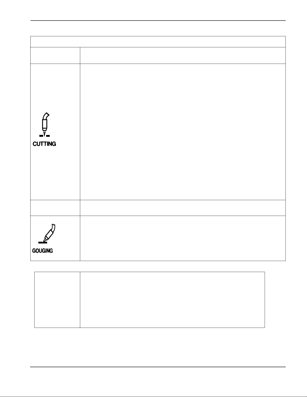
OPERATION
HySpeed HT2000LHF Instruction Manual 4-11
9
CUT CHART AND CONSUMABLE PARTS INDEX
Plasma Gas/ Retaining Swirl
Metal Amps Shield Gas Shield Cap Nozzle Ring Electrode Page
Mild
Steel
Mild
Steel
Mild
Steel
Stainless
Steel
Stainless
Steel
Aluminum
Aluminum
200 HySpeed O
2
/ Air 220239 220242 220237 220236 220235 4-12
200 O
2
/ Air 020424 120837 020605 120833 120667 4-13
200 Air / Air 020424 120837 020608 020679 120667 4-14
200 N
2
/ CO
2
020424 120837 020608 020607 020415 4-15
100 Air / Air 020448 120837 020611 020607 120547 4-16
100 O
2
/ Air 020424 120837 020690 020613 120547 4-17
50 O
2
/ O
2
120186 120185 120182 120179 120178 4-18
200 Air / Air 020424 120837 020608 020679 120667 4-19
200 N
2
/ Air 020424 120837 020608 020607 020415 4-20
200 N
2
/ CO
2
020424 120837 020608 020607 020415 4-21
200 H35 / N
2
* 020602 120837 020608 020607 020415 Ap-A
100 Air / Air 020448 120837 020611 020607 120547 4-22
100 H35 / N
2
* 020448 120837 020611 020607 020415 Ap-A
40 Air / Air 020688 020423 020689 020613 120667 4-23
200 Air / Air 020424 120837 020608 020679 120667 4-24
200 N2/ Air 020424 120837 020608 020607 020415 4-25
200 N
2
/ CO
2
020424 120837 020608 020607 020415 4-26
200 H35 / N
2
* 020602 120837 020608 020607 020415 Ap-A
100 Air / Air 020448 120837 020611 020607 120547 4-27
100 H35 / N
2
* 020448 120837 020611 020607 020415 Ap-A
40 Air / Air 020688 020423 020689 020613 120667 4-28
200 O
2
/Air 120260 120837 120259 120833 120258 4-29
200 Air / Air 020485 120837 020615 020607 120667 4-30
200 H35 / N2* 020485 120837 020615 020607 020415 Ap-A
200 H35 / N
2
* 020485 120837 020615 020607 020415 Ap-A
BEVEL
CUTTING
* Argon-Hydrogen Manifold required. See appendix for installation and operation with argon-hydrogen manifold.
** Do not use the water muffler when cutting with argon-hydrogen (H35)!
Water Muffler cannot be used with the stainless steel torch
Note: If the Command THC or other ohmic contact sensing device is NOT in use, retaining caps with no IHS tab: 020423
clockwise; 020955 counterclockwise can be used for all cutting currents except 50A; 120185 for 50A cutting only.
For HySpeed
200A O
2
cutting only; use retaining cap part # 220238 (clockwise cutting) & 220241 (counter-clockwise cutting).
200 HySpeed O2/ Air 220239 220238 220237 220236 220235
200 O
2
/ Air 020566 020423 020605 120833 120667
100 O
2
/ Air 020566 020423 020690 020613 120547
200 Air / Air 020566 020423 020608 020679 120667
100 Air / Air 020618 020423 020611 020607 120547
200 N
2
/ CO
2
020566 020423 020608 020607 020415
200 N
2
/ Air 020566 020423 020608 020607 020415
Consumables
used with
HySpeed
HT2000LHF
Water Muffler**
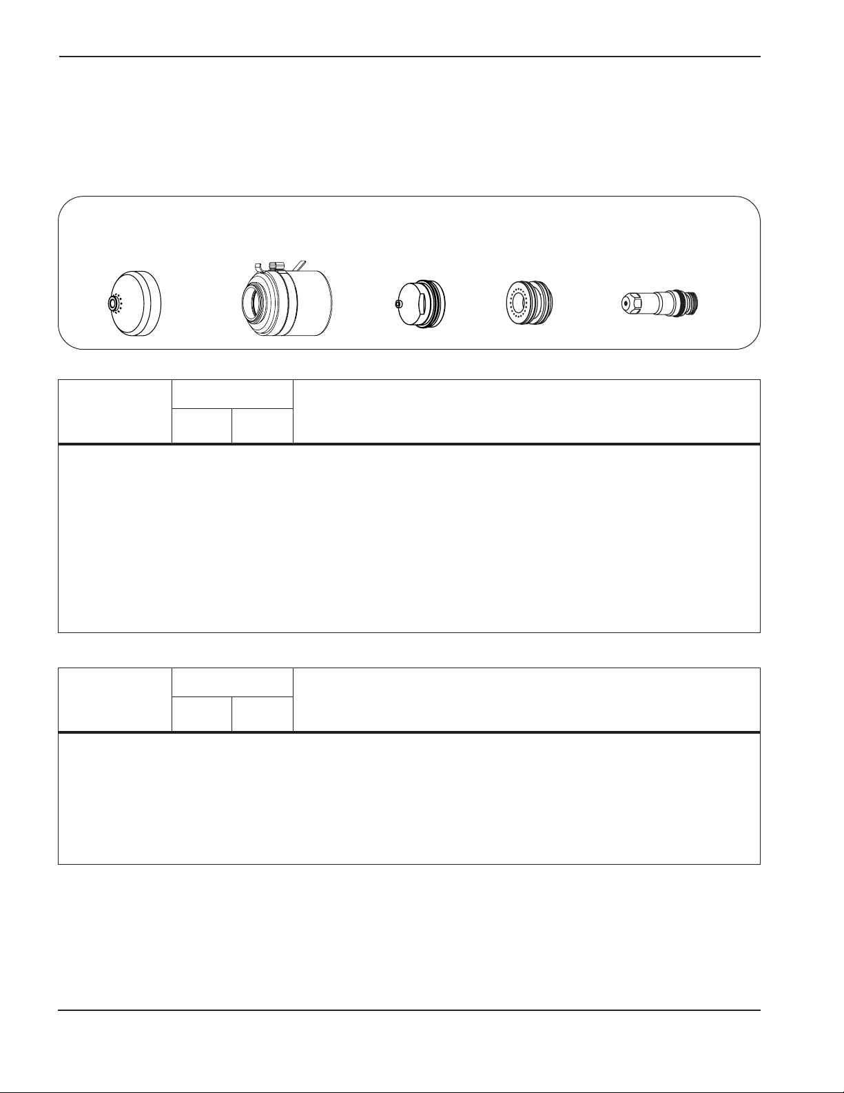
9
OPERATION
4-12 HySpeed HT2000LHF Instruction Manual
Shield Arc Approx.
Material
Plasma Gas Flow Rate %
Gas (Air) Torch-to-work Initial Torch Voltage Motion
Thickness Preflow Cutflow Pressure Distance Piercing Height Setting Travel Speed Delay Time
(inches) (mm) (O2%N2%) (O2%N2%) (psi) (inches) (mm) (inches) (mm) (volts) (ipm) (mm/min.) (sec)
Shield Arc Approx.
Material
Plasma Gas Flow Rate %
Gas (Air) Torch-to-work Initial Torch Voltage Motion
Thickness Preflow Cutflow Pressure Distance Piercing Height Setting Travel Speed Delay Time
(inches) (mm) (O2%N2%) (O2%N2%) (psi) (inches) (mm) (inches) (mm) (volts) (ipm) (mm/min.) (sec)
1/4 6 12 38 76 0 60 1/16 1.5 1/8 3 145 230 5800 0.3
5/16 8 (12 / 50 (90 / 0 (275 1/8 3 1/4 6 151 165 4200 0.3
3/8 10 SCFH) SCFH) SCFH) 5/32 4 5/16 8 155 140 3500 0.3
1/2 12 1/8 3 1/4 6 155 120 3000 0.3
5/8 15 1/8 3 1/4 6 155 100 2500 0.5
3/4 20 1/8 3 1/4 6 155 75 1900 0.6
7/8 22 1/8 3 1/4 6 159 60 1500 0.7
1 25 1/8 3 1/4 6 160 50 1300 0.7
1 1/4 32 1/8 3 5/16 8 168 30 760 2.6
1-1/2 38 1/8 3 5/16 8 175 20 500 4.0
1-3/4 44 1/8 3 N/A N/A 180 15 380 N/A
2 50 1/8 3 N/A N/A 188 10 250 N/A
Mild Steel
HySpeed 200 amps • O2Plasma / Air Shield
This gas combination gives superior cut speed, minimum dross, minimum surface nitriding and excellent
weldability.
Notes: Set oxygen plasma gas inlet pressure to 120 psi (8.3 bar).
Set nitrogen plasma gas inlet pressure to 120 psi (8.3 bar)
Set shield gas inlet pressure to 90 psi (6.2 bar)
Production cutting above 1" (25 mm) not recommended.
Drop cutting above 1-1/2" (38 mm) not recommended
Above Water
1/4 6 12 38 76 0 60 1/16 1.5 1/8 3 149 230 5800 0.3
5/16 8 (12 / 50 (90 / 0 (275 1/8 3 1/4 6 151 165 4200 0.3
3/8 10 SCFH) SCFH) SCFH) 5/32 4 5/16 8 159 140 3500 0.3
1/2 12 1/8 3 1/4 6 155 105 2700 0.3
5/8 15 1/8 3 1/4 6 161 90 2300 0.5
3/4 20 1/8 3 1/4 6 161 65 1600 0.6
7/8 22 1/8 3 1/4 6 161 55 1400 0.7
1 25 1/8 3 1/4 6 164 45 1100 0.7
3" Under Water
220235
Electrode
220237
Nozzle
220242 (cw)
220243 (ccw)
Retaining cap
220239
Shield
220236 (cw)
220244 (ccw)
Swirl ring

OPERATION
HySpeed HT2000LHF Instruction Manual 4-13
7
Shield Arc Approx.
Material
Plasma Gas Flow Rate %
Gas (Air) Torch-to-work Initial Torch Voltage Motion
Thickness Preflow Cutflow Pressure Distance Piercing Height Setting Travel Speed Delay Time
(inches) (mm) (O2%N2%) (O2%N2%) (psi) (inches) (mm) (inches) (mm) (volts) (ipm) (mm/min.) (sec)
Shield Arc Approx.
Material
Plasma Gas Flow Rate %
Gas (Air) Torch-to-work Initial Torch Voltage Motion
Thickness Preflow Cutflow Pressure Distance Piercing Height Setting Travel Speed Delay Time
(inches) (mm) (O2%N2%) (O2%N2%) (psi) (inches) (mm) (inches) (mm) (volts) (ipm) (mm/min.) (sec)
1/4 6 12 38 64 0 60 1/8 3 1/4 6 120 160 4060 0.5
.315 8 (14.9 / 50.4 (79.6 / 0 (270 1/8 3 1/4 6 125 120 3000 0.5
3/8 10 SCFH) SCFH) SCFH) 1/8 3 1/4 6 125 100 2540 1.0
1/2 12 .157 4 .314 8 125 80 2030 2.0
5/8 15 .157 4 .314 8 130 70 1780 2.0
3/4 20 3/16 5 3/8 10 135 55 1400 2.5
7/8 22 1/4 6 1/2 12 135 45 1140 2.5
1 25 1/4 6 1/2 12 140 35 890 2.5
1 1/4 32 1/4 6 150 22 560
1-1/2 38 1/4 6 155 15 380
1-3/4 44 5/16 8 165 10 250
2 50 5/16 8 170 7 180
Mild Steel
200 amps • O2Plasma / Air Shield
This gas combination gives superior cut speed, minimum dross, minimum surface nitriding and excellent
weldability.
Above Water
1/4 6 12 38 64 0 70 1/8 3 1/4 6 125 145 3700 0.5
.315 8 (14.9 / 50.4 (79.6 / 0 (270 1/8 3 1/4 6 125 110 2800 0.5
3/8 10 SCFH) SCFH) SCFH) 1/8 3 1/4 6 130 80 2000 1.0
1/2 12 1/8 3 1/4 6 130 70 1800 2.0
5/8 15 .157 4 .314 8 135 60 1500 2.0
3/4 20 3/16 5 3/8 10 140 48 1200 2.5
7/8 22 1/4 6 1/2 12 140 38 950 3.0
1 25 1/4 6 1/2 12 145 25 680 3.0
3" Under Water
120833* (cw)
120834 (ccw)
Swirl ring
020605
Nozzle
120837 (cw)
120838 (ccw)
Retaining cap
020424
Shield
120667 (standard)
Electrode
220084 (optional)
SilverPlus electrode
+
Notes: Set oxygen plasma gas inlet pressure to 120 psi (8.3 bar).
Set nitrogen plasma gas inlet pressure to 120 psi (8.3 bar)
Set shield gas inlet pressure to 90 psi (6.2 bar)
Production cutting above 1" (25 mm) not recommended. Drop cutting above 1-1/2" (38 mm) not recommended
* Use 020679 swirl ring in place of 120833 swirl ring to obtain smoother cut edges on material
1/4" to 3/8" thick, but expect a 30-40% decrease in electrode life
+ SilverPlus provides increased life to high duty cycle users in most applications. The hafnium wears to
approximately twice the depth of a standard electrode (120667). Arc voltage may need to be increased by 5-10
volts throughout the electrode life to maintain proper cut height parameters.

OPERATION
4-14 HySpeed HT2000LHF Instruction Manual
7
Shield Arc Approx.
Material
Plasma Gas Flow Rate %
Gas (Air) Torch-to-work Initial Torch Voltage Motion
Thickness Preflow Cutflow Pressure Distance Piercing Height Setting Travel Speed Delay Time
(inches) (mm) (Air %) (Air %) (psi) (inches) (mm) (inches) (mm) (volts) (ipm) (mm/min.) (sec)
Shield Arc Approx.
Material
Plasma Gas Flow Rate %
Gas (Air) Torch-to-work Initial Torch Voltage Motion
Thickness Preflow Cutflow Pressure Distance Piercing Height Setting Travel Speed Delay Time
(inches) (mm) (Air %) (Air %) (psi) (inches) (mm) (inches) (mm) (volts) (ipm) (mm/min.) (sec)
3/16 5 54 65 60 1/8 3 1/4 6 130 200 5080
1/4 6 (62.3 (75.0 (270 1/8 3 1/4 6 130 135 3400 0.5
.315 8 SCFH) SCFH) SCFH) 1/8 3 1/4 6 135 115 2900 0.5
3/8 10 1/8 3 1/4 6 135 100 2540 1.0
1/2 12 .157 4 .314 8 140 80 2030 2.0
5/8 15 .157 4 .314 8 145 60 1520 2.0
3/4 20 3/16 5 3/8 10 150 45 1140 2.5
7/8 22 1/4 6 1/2 12 155 30 760 2.5
1 25 1/4 6 1/2 12 160 25 635 2.5
1-1/4 32 1/4 6 165 15 380
1-1/2 38 1/4 6 170 10 250
1-3/4 44 5/16 8 180 7 180
2 50 5/16 8 185 5 130
Mild Steel
200 amps • Air Plasma / Air Shield
This gas combination gives good cut speed, low dross levels and is very economical. Some surface nitriding can
occur.
Notes: Set plasma gas inlet pressure to 90 psi (6.2 bar)
Set shield gas inlet pressure to 90 psi (6.2 bar)
Production cutting above 1" (25 mm) not recommended
Drop cutting above 1-1/2" (38 mm) not recommended
Above Water
1/4 6 54 65 70 1/8 3 1/4 6 130 130 3300 0.5
.315 8 (62.3 (75.0 (280 1/8 3 1/4 6 135 110 2700 0.5
3/8 10 SCFH) SCFH) SCFH) 1/8 3 1/4 6 135 95 2400 1.0
1/2 12 1/8 3 1/4 6 140 75 1900 2.0
5/8 15 .157 4 .314 8 145 50 1200 2.0
3/4 20 3/16 5 3/8 10 150 35 850 2.5
7/8 22 1/4 6 1/2 12 155 20 530 3.0
1 25 1/4 6 1/2 12 165 15 400 3.0
3" Under Water
020424
Shield
120837
Retaining cap
020608
Nozzle
020679
Swirl ring
120667
Electrode

OPERATION
HySpeed HT2000LHF Instruction Manual 4-15
Shield Arc Approx.
Material
Plasma Gas Flow Rate %
Gas (CO2) Torch-to-work Initial Torch Voltage Motion
Thickness Preflow Cutflow Pressure Distance Piercing Height Setting Travel Speed Delay Time
(inches) (mm) (N2%) (N2%) (psi) (inches) (mm) (inches) (mm) (volts) (ipm) (mm/min.) (sec)
3/16 5 50 60 60/4 1/8 3 1/4 6 120 130 3300 0.5
1/4 6 (62.3 (75.0 (270 1/8 3 1/4 6 125 110 2800 1.0
3/8 10 (SCFH) SCFH) SCFH) 1/8 3 1/4 6 130 85 2160 1.5
1/2 12 1/8 3 1/4 6 130 55 1400 2.0
5/8 15 .157 4 .314 8 135 45 1140 2.0
3/4 20 3/16 5 3/8 10 145 25 635 2.5
7/8 22 1/4 6 1/2 12 150 20 510 3.0
1 25 1/4 6 1/2 12 160 15 380 3.0
1-1/4 32 1/4 6 165 10 250
1-1/2 38 1/4 6 175 5 130
Mild Steel
200 amps • N2Plasma / CO2Shield
This gas combination may be used when cut edge quality and surface nitriding are less important. Electrode life is
extended when using this combination.
Notes: Set plasma gas inlet pressure to 120 psi (8.3 bar)
Set shield gas inlet pressure to 90 psi (6.2 bar)
Production cutting above 1" (25 mm) not recommended
Above Water Only
020424
Shield
120837
Retaining cap
020608
Nozzle
020607
Swirl ring
020415
Electrode
7

OPERATION
4-16 HySpeed HT2000LHF Instruction Manual
7
Shield Arc Approx.
Material
Plasma Gas Flow Rate %
Gas (Air) Torch-to-work Initial Torch Voltage Motion
Thickness Preflow Cutflow Pressure Distance Piercing Height Setting Travel Speed Delay Time
(inches) (mm) (Air %) (Air %) (psi) (inches) (mm) (inches) (mm) (volts) (ipm) (mm/min.) (sec)
Shield Arc Approx.
Material
Plasma Gas Flow Rate %
Gas (Air) Torch-to-work Initial Torch Voltage Motion
Thickness Preflow Cutflow Pressure Distance Piercing Height Setting Travel Speed Delay Time
(inches) (mm) (Air %) (Air %) (psi) (inches) (mm) (inches) (mm) (volts) (ipm) (mm/min.) (sec)
.075* 2 48 39 60 3/32 2.5 3/16 5 120 235 6050
1/8 3 (55.3 (44.9 (270 3/32 2.5 3/16 5 125 185 4700 0.5
3/16 5 SCFH) SCFH) SCFH) 1/8 3 1/4 6 125 175 4450 0.5
1/4 6 1/8 3 1/4 6 130 125 3175 0.5
3/8 10 1/8 3 1/4 6 135 50 1270 1.0
1/2 12 1/8 3 140 35 890
5/8 15 .157 4 145 25 635
3/4 20 3/16 5 150 20 510
Mild Steel
100* amps • Air Plasma / Air Shield
This gas combination gives good cut speed, low dross levels and is very economical. Some surface nitriding can
occur. While this process may be used on thicker materials, optimal recommended range is to 3/8" (10mm).
* Set arc current to 80 amps when cutting .075" (2 mm) thick mild steel
Notes: Set plasma gas inlet pressure to 90 psi (6.2 bar)
Set shield gas inlet pressure to 90 psi (6.2 bar)
Production cutting above 3/8" (10 mm) not recommended
Above Water
1/8 3 48 39 70 5/64 2 5/32 4 130 120 3050
3/16 5 (55.3 (44.9 (270 1/8 3 1/4 6 135 90 2300 0.5
1/4 6 SCFH) SCFH) SCFH) 1/8 3 1/4 6 140 70 1730 0.5
3/8 10 1/8 3 1/4 6 145 42 1050 0.5
1/2 12 1/8 145 28 700
3" Under Water
020448
Shield
120837
Retaining cap
020611
Nozzle
020607
Swirl ring
120547
Electrode

OPERATION
HySpeed HT2000LHF Instruction Manual 4-17
Shield Arc Approx.
Material
Plasma Gas Flow Rate %
Gas (Air) Torch-to-work Initial Torch Voltage Motion
Thickness Preflow Cutflow Pressure Distance Piercing Height Setting Travel Speed Delay Time
(inches) (mm) (O2%N2%) (O2%N2%) (psi) (inches) (mm) (inches) (mm) (volts) (ipm) (mm/min.) (sec)
Shield Arc Approx.
Material
Plasma Gas Flow Rate %
Gas (Air) Torch-to-work Initial Torch Voltage Motion
Thickness Preflow Cutflow Pressure Distance Piercing Height Setting Travel Speed Delay Time
(inches) (mm) (O2%N2%) (O2%N2%) (psi) (inches) (mm) (inches) (mm) (volts) (ipm) (mm/min.) (sec)
1/8 3 728 360 60 3/32 2.5 3/16 5 125 240 6100
3/16 5 (9 / 37 (45 / 0 (270 1/8 3 1/4 6 125 180 4570
1/4 6 SCFH) SCFH) SCFH) 1/8 3 1/4 6 125 120 3050 0.5
3/8 10 1/8 3 1/4 6 130 90 2280 0.5
1/2 12 1/8 3 130 60 1520
5/8 15 .157 4 140 45 1140
3/4 20 3/16 5 145 30 760
Mild Steel
100 amps • O2Plasma / Air Shield
This gas combination gives good cut speed, low dross and is very economical. Some surface nitriding can occur.
While this process may be used on thicker materials, optimal recommended range is to 3/8" (10mm).
Notes: Set oxygen plasma gas inlet pressure to 120 psi (8.3 bar)
Set nitrogen plasma gas inlet pressure to 120 psi (8.3 bar)
Set shield gas inlet pressure to 90 psi (6.2 bar)
Production cutting above 3/8" (10 mm) not recommended
* To maximize consumable life, modify the part lead-in and lead-out to reduce ramp-down errors.
For strip cutting or other applications where proper ramp-down is difficult to achieve, use electrode P/N 120667 in
place of electrode P/N120547.
Above Water
1/8 3 728 360 60 5/64 2 5/32 4 125 220 5580
3/16 5 (9 / 37 (45 / 0 (270 1/8 3 1/4 6 125 160 4060 0.5
1/4 6 SCFH) SCFH) SCFH) 1/8 3 1/4 6 125 110 2790 0.5
3/8 10 1/8 3 1/4 6 130 85 2160 0.5
1/2 12 1/8 3 135 60 1520
3" Under Water
020613 (cw)
120252 (ccw)
Swirl ring
120547*
Electrode
020690
Nozzle
120837 (cw)
120838 (ccw)
Retaining cap
020424
Shield
7

OPERATION
4-18 HySpeed HT2000LHF Instruction Manual
7
Shield Arc Approx.
Material
Plasma Gas Flow Rate %
Gas (O2) Torch-to-work Initial Torch Voltage Motion
Thickness Preflow Cutflow Pressure Distance Piercing Height Setting Travel Speed Delay Time
(inches) (mm) (O2%N2%) (O2%N2%) (psi) (inches) (mm) (inches) (mm) (volts) (ipm) (mm/min.) (sec)
.048 (18 GA.) 327 300 18 .060 1.50 .120 3.0 108 160 4060 0
.074 (14 GA.) 2 / 17 18 / 0 17 .060 1.50 .120 3.0 108 120 3050 0.3
.100 (12 GA.) l/min l/min l/min .070 1.75 .140 3.5 113 100 2540 0.3
.125 (10 GA.) .080 2.00 .160 4.0 118 60 1520 0.5
Mild Steel
50 amps • O2Plasma / O2Shield
Notes: Set oxygen plasma gas inlet pressure to 120 psi (8.3 bar)
Set nitrogen plasma gas inlet pressure to 120 psi (8.3 bar)
Set shield gas inlet pressure to 120 psi (8.3 bar)
The oxygen shield gas must be supplied from a regulator separate from the oxygen plasma gas regulator.
If using the Digital Remote (DR) or Programmable Remote (PR), set current to 60 amps.
If using a torch height control system capable of achieving the arc voltage setting on this chart, set accordingly.
If using a less sensitive torch height control system, round off the arc voltage numbers to the nearest achievable
setting.
Torch-to-work Distance tolerances are ± .010 inch (± .25 mm). When using a THC the tolerances are ± 1 volt.
Stay within travel speed ranges to produce dross-free cuts.
Due to the low gas flow rates associated with the 50 amp process, initial cut quality may be degraded while nitrogen is
being purged from the gas line when changing from preflow to cut flow (up to 2 seconds). To compensate, either
increase machine motion delay or increase the lead-in distance at the start of the cut.
Note that some height control systems may need to be locked out to prevent the torch from diving into the plate if the
machine motion delay option is used.
Above Water Only
120185
Retaining cap
120186
Shield
120182
Nozzle
120179
Swirl ring
120178
Electrode

OPERATION
HySpeed HT2000LHF Instruction Manual 4-19
Shield Arc Approx.
Material
Plasma Gas Flow Rate %
Gas (Air) Torch-to-work Initial Torch Voltage Motion
Thickness Preflow Cutflow Pressure Distance Piercing Height Setting Travel Speed Delay Time
(inches) (mm) (Air %) (Air %) (psi) (inches) (mm) (inches) (mm) (volts) (ipm) (mm/min.) (sec)
Shield Arc Approx.
Material
Plasma Gas Flow Rate %
Gas (Air) Torch-to-work Initial Torch Voltage Motion
Thickness Preflow Cutflow Pressure Distance Piercing Height Setting Travel Speed Delay Time
(inches) (mm) (Air %) (Air %) (psi) (inches) (mm) (inches) (mm) (volts) (ipm) (mm/min.) (sec)
3/16 5 54 65 60 1/8 3 1/4 5 125 220 5600
1/4 6 (62.3 (75.0 (270 1/8 3 1/4 6 130 195 5000 0.5
3/8 10 SCFH) SCFH) SCFH) 1/8 3 1/4 6 130 145 3700 1.0
1/2 12 1/8 3 1/4 6 135 105 2700 2.0
5/8 15 .157 4 .314 8 140 75 1900 2.0
3/4 20 3/16 5 3/8 10 140 55 1400 2.5
7/8 22 1/4 6 1/2 12 145 40 1000 3.0
1 25 1/4 6 150 30 760
1-1/4 32 ` 1/4 6 160 15 380
1-1/2 38 1/4 6 170 10 250
Stainless Steel
200 amps • Air Plasma / Air Shield
This gas combination gives good cut speed, low dross and is very economical. Some surface nitriding and surface
oxidation of alloying elements can occur.
Notes: Set air plasma gas inlet pressure to 90 psi (6.2 bar)
Set air shield gas inlet pressure to 90 psi (6.2 bar)
Production cutting above 7/8" (22 mm) not recommended
Above Water
3/16 5 54 65 70 1/8 3 1/4 6 125 210 5320
1/4 6 (62.3 (75.0 (280 1/8 3 1/4 6 130 180 4500 0.5
3/8 10 SCFH) SCFH) SCFH) 1/8 3 1/4 6 135 125 3150 1.0
1/2 12 1/8 3 1/4 6 140 90 2300 2.0
5/8 15 .157 4 .314 8 145 60 1520 2.0
3/4 20 3/16 5 3/8 10 145 45 1150 2.5
7/8 22 1/4 6 1/2 12 150 30 750 3.0
1 25 1/4 6 155 22 570
3" Under Water
020424
Shield
120837
Retaining cap
020608
Nozzle
020679
Swirl ring
120667
Electrode
7

OPERATION
4-20 HySpeed HT2000LHF Instruction Manual
7
Shield Arc Approx.
Material
Plasma Gas Flow Rate %
Gas (Air) Torch-to-work Initial Torch Voltage Motion
Thickness Preflow Cutflow Pressure Distance Piercing Height Setting Travel Speed Delay Time
(inches) (mm) (N2%) (N2%) (psi) (inches) (mm) (inches) (mm) (volts) (ipm) (mm/min.) (sec)
Shield Arc Approx.
Material
Plasma Gas Flow Rate %
Gas (Air) Torch-to-work Initial Torch Voltage Motion
Thickness Preflow Cutflow Pressure Distance Piercing Height Setting Travel Speed Delay Time
(inches) (mm) (N2%) (N2%) (psi) (inches) (mm) (inches) (mm) (volts) (ipm) (mm/min.) (sec)
3/16 5 50 60 60 1/8 3 1/4 5 125 135 3430
1/4 6 (66.4 (79.6 (270 1/8 3 1/4 6 130 120 3050 0.5
3/8 10 SCFH) SCFH) SCFH) 1/8 3 1/4 6 130 100 2540 1.0
1/2 12 1/8 3 1/4 6 135 75 1900 2.0
5/8 15 .157 4 .314 8 140 60 1520 2.0
3/4 20 3/16 5 3/8 10 140 45 1140 2.5
7/8 22 1/4 6 1/2 12 145 35 890 2.5
1 25 1/4 6 150 20 510
1-1/4 32 ` 1/4 6 160 15 380
1-1/2 38 1/4 6 160 10 250
Stainless Steel
200 amps • N2Plasma / Air Shield
This gas combination is used when cut edge quality, surface nitriding and surface oxidation of alloying elements
are less important. Electrode life is extended when this combination is used.
Notes: Set nitrogen plasma gas inlet pressure to 120 psi (8.3 bar)
Set air shield gas inlet pressure to 90 psi (6.2 bar)
Production cutting above 7/8" (22 mm) not recommended
Above Water
3/16 5 50 60 70 1/8 3 1/4 6 125 130 3250
1/4 6 (66.4 (79.6 (280 1/8 3 1/4 6 130 110 2750 0.5
3/8 10 SCFH) SCFH) SCFH) 1/8 3 1/4 6 135 85 2160 1.0
1/2 12 1/8 3 1/4 6 140 60 1520 2.0
5/8 15 .157 4 .314 8 145 45 1140 2.0
3/4 20 3/16 5 3/8 10 145 30 800 2.5
3" Under Water
020424
Shield
120837
Retaining cap
020608
Nozzle
020607
Swirl ring
020415
Electrode

OPERATION
HySpeed HT2000LHF Instruction Manual 4-21
Shield Arc Approx.
Material
Plasma Gas Flow Rate %
Gas (CO
2
) Torch-to-work Initial Torch Voltage Motion
Thickness Preflow Cutflow Pressure Distance Piercing Height Setting Travel Speed Delay Time
(inches) (mm) (N
2
%) (N2%) (psi) (inches) (mm) (inches) (mm) (volts) (ipm) (mm/min.) (sec)
Shield Arc Approx.
Material
Plasma Gas Flow Rate %
Gas (CO2) Torch-to-work Initial Torch Voltage Motion
Thickness Preflow Cutflow Pressure Distance Piercing Height Setting Travel Speed Delay Time
(inches) (mm) (N2%) (N2%) (psi) (inches) (mm) (inches) (mm) (volts) (ipm) (mm/min.) (sec)
3/16 5 50 60 60 1/8 3 1/4 6 125 190 4800 0.5
1/4 6 (66.4 (79.6 (210 1/8 3 1/4 6 130 170 4300 1.0
3/8 10 SCFH) SCFH) SCFH) 1/8 3 1/4 6 130 125 3200 1.5
1/2 12 1/8 3 1/4 6 135 95 2400 2.0
5/8 15 .157 4 .314 8 140 70 1800 2.0
3/4 20 3/16 5 3/8 10 140 50 1250 2.5
7/8 22 1/4 6 1/2 12 145 40 1000 3.0
1 25 1/4 6 150 30 760
1-1/4 32 ` 1/4 6 160 15 380
1-1/2 38 1/4 6 170 10 250
Stainless Steel
200 amps • N2Plasma / CO2Shield
This gas combination is used when surface nitriding and surface oxidation of alloying elements is less important.
Electrode life is extended when using this gas combination.
Notes: Set nitrogen plasma gas inlet pressure to 120 psi (8.3 bar)
Set carbon dioxide shield gas inlet pressure to 90 psi (6.2 bar)
Production cutting above 7/8" (22 mm) not recommended
Above Water
3/16 5 50 60 60 1/8 3 1/4 6 125 180 4550 0.5
1/4 6 (66.4 (79.6 (210 1/8 3 1/4 6 130 150 3850 1.0
3/8 10 SCFH) SCFH) SCFH) 1/8 3 1/4 6 135 110 2700 1.5
1/2 12 1/8 3 1/4 6 140 75 1920 2.0
5/8 15 .157 4 .314 8 145 50 1350 2.0
3/4 20 3/16 5 3/8 10 145 38 950 2.5
7/8 22 1/4 6 1/2 12 150 28 700 3.0
3" Under Water
020424
Shield
120837
Retaining cap
020608
Nozzle
020607
Swirl ring
020415
Electrode
7

OPERATION
4-22 HySpeed HT2000LHF Instruction Manual
7
Shield Arc Approx.
Material
Plasma Gas Flow Rate %
Gas (Air) Torch-to-work Initial Torch Voltage Motion
Thickness Preflow Cutflow Pressure Distance Piercing Height Setting Travel Speed Delay Time
(inches) (mm) (Air %) (Air %) (psi) (inches) (mm) (inches) (mm) (volts) (ipm) (mm/min.) (sec)
Shield Arc Approx.
Material
Plasma Gas Flow Rate %
Gas (Air) Torch-to-work Initial Torch Voltage Motion
Thickness Preflow Cutflow Pressure Distance Piercing Height Setting Travel Speed Delay Time
(inches) (mm) (Air %) (Air %) (psi) (inches) (mm) (inches) (mm) (volts) (ipm) (mm/min.) (sec)
1/8 3 48 39 60 3/32 2.5 3/16 5 125 140 3560
3/16 5 (53.3 (44.9 (270 1/8 3 1/4 6 130 110 2800 0.5
1/4 6 SCFH) SCFH) SCFH) 1/8 3 1/4 6 130 80 2030 0.5
3/8 10 1/8 3 1/4 6 135 55 1400 0.5
1/2 12 1/8 3 140 35 890
5/8 15 .157 4 145 25 635
3/4 20 3/16 5 150 20 510
Stainless Steel
100 amps • Air Plasma / Air Shield
This gas combination gives good cut speed, low dross and is very economical. Some surface nitriding and surface
oxidation of alloying elements can occur.
Notes: Set air plasma gas inlet pressure to 90 psi (6.2 bar)
Set air shield gas inlet pressure to 90 psi (6.2 bar)
Production cutting above 3/8" (10 mm) not recommended
Above Water
1/8 3 48 39 60 5/64 2 5/32 4 125 135 3400
3/16 5 (53.3 (44.9 (270 1/8 3 1/4 6 130 100 2520 0.5
1/4 6 SCFH) SCFH) SCFH) 1/8 3 1/4 6 135 65 1720 0.5
3/8 10 1/8 3 1/4 6 140 45 1120 0.5
1/2 12 1/8 3 145 25 670
3" Under Water
020448
Shield
120837
Retaining cap
020611
Nozzle
020607
Swirl ring
120547
Electrode

OPERATION
HySpeed HT2000LHF Instruction Manual 4-23
Shield Arc Approx.
Material
Plasma Gas Flow Rate %
Gas (Air) Torch-to-work Initial Torch Voltage Motion
Thickness Preflow Cutflow Pressure Distance Piercing Height Setting Travel Speed Delay Time
(inches) (mm) (Air %) (Air %) (psi) (inches) (mm) (inches) (mm) (volts) (ipm) (mm/min.) (sec)
.050 (18 GA.) 40 20 60 3/32 2.5 3/16 5 120 145 3700
1/16 1.5 (46.0 (23.1 (275 3/32 2.5 3/16 5 120 120 3050
1/8 3 SCFH) SCFH) SCFH) 3/32 2.5 3/16 5 125 75 1900 0.5
1/4 6 1/8 3 135 24 610
3/8 10 1/8 3 140 12 300
Stainless Steel
40 amps • Air Plasma / Air Shield
This gas combination gives good cut speed, low dross level and is very economical. Some surface nitriding and
surface oxidation of alloying elements can occur.
Notes: Set air plasma gas inlet pressure to 90 psi (6.2 bar)
Set air shield gas inlet pressure to 90 psi (6.2 bar)
Production cutting above 1/8" (3 mm) not recommended
Above Water Only
020688
Shield
120837
Retaining cap
020689
Nozzle
020613
Swirl ring
120667
Electrode
7

OPERATION
4-24 HySpeed HT2000LHF Instruction Manual
7
Shield Arc Approx.
Material
Plasma Gas Flow Rate %
Gas (Air) Torch-to-work Initial Torch Voltage Motion
Thickness Preflow Cutflow Pressure Distance Piercing Height Setting Travel Speed Delay Time
(inches) (mm) (Air %) (Air %) (psi) (inches) (mm) (inches) (mm) (volts) (ipm) (mm/min.) (sec)
Shield Arc Approx.
Material
Plasma Gas Flow Rate %
Gas (Air) Torch-to-work Initial Torch Voltage Motion
Thickness Preflow Cutflow Pressure Distance Piercing Height Setting Travel Speed Delay Time
(inches) (mm) (Air %) (Air %) (psi) (inches) (mm) (inches) (mm) (volts) (ipm) (mm/min.) (sec)
3/16 5 54 65 60 1/8 3 1/4 6 130 220 5600 0.5
1/4 6 (62.3 (75.0 (270 1/8 3 1/4 6 140 190 4800 1.0
3/8 10 SCFH) SCFH) SCFH) 1/8 3 1/4 6 140 145 3700 2.0
1/2 12 1/8 3 1/4 6 145 110 2800 2.5
5/8 15 .157 4 .314 8 150 85 2200 2.5
3/4 20 3/16 5 3/8 10 155 65 1650 2.5
7/8 22 1/4 6 1/2 12 160 50 1300 2.5
1 25 1/4 6 165 35 900
1-1/4 32 ` 1/4 6 170 20 500
1-1/2 38 1/4 6 175 12 300
Aluminum
200 amps • Air Plasma / Air Shield
This gas combination gives good cut speed, low dross levels and is very economical.
Notes: Set plasma gas inlet pressure to 90 psi (6.2 bar)
Set shield gas inlet pressure to 90 psi (6.2 bar)
Production cutting above 7/8" (22 mm) not recommended
Above Water
3/16 5 54 65 70 1/8 3 1/4 6 135 210 5300 0.5
1/4 6 (62.3 (75.0 (280 1/8 3 1/4 6 140 170 4300 1.0
3/8 10 SCFH) SCFH) SCFH) 1/8 3 1/4 6 145 125 3150 2.0
1/2 12 1/8 3 1/4 6 150 90 2240 2.5
5/8 15 .157 4 .314 8 155 65 1650 3.0
3/4 20 3/16 5 3/8 10 160 45 1150 3.0
3" Under Water
020424
Shield
120837
Retaining cap
020608
Nozzle
020679
Swirl ring
120667
Electrode

OPERATION
HySpeed HT2000LHF Instruction Manual 4-25
Shield Arc Approx.
Material
Plasma Gas Flow Rate %
Gas (Air) Torch-to-work Initial Torch Voltage Motion
Thickness Preflow Cutflow Pressure Distance Piercing Height Setting Travel Speed Delay Time
(inches) (mm) (N2%) (N2%) (psi) (inches) (mm) (inches) (mm) (volts) (ipm) (mm/min.) (sec)
Shield Arc Approx.
Material
Plasma Gas Flow Rate %
Gas (Air) Torch-to-work Initial Torch Voltage Motion
Thickness Preflow Cutflow Pressure Distance Piercing Height Setting Travel Speed Delay Time
(inches) (mm) (N2%) (N2%) (psi) (inches) (mm) (inches) (mm) (volts) (ipm) (mm/min.) (sec)
3/16 5 50 60 60 1/8 3 1/4 6 130 180 4570 0.5
1/4 6 (66.4 (79.6 (270 1/8 3 1/4 6 135 160 4060 1.0
3/8 10 SCFH) SCFH) SCFH) 1/8 3 1/4 6 135 120 3050 1.5
1/2 12 1/8 3 1/4 6 140 80 2030 2.0
5/8 15 .157 4 .314 8 140 70 1780 2.0
3/4 20 3/16 5 3/8 10 150 50 1270 2.5
7/8 22 1/4 6 1/2 12 160 35 890 2.5
1 25 1/4 6 165 25 635
1-1/4 32 ` 1/4 6 175 20 510
1-1/2 38 1/4 6 185 10 250
Aluminum
200 amps • N2Plasma / Air Shield
This gas combination is used when cut edge quality is less important. Electrode life is extended when this
combination is used.
Notes: Set plasma gas inlet pressure to 120 psi (8.3 bar)
Set shield gas inlet pressure to 90 psi (6.2 bar)
Production cutting above 7/8" (22 mm) not recommended
Above Water
3/16 5 50 60 70 1/8 3 1/4 6 135 170 4350 0.5
1/4 6 (66.4 (79.6 (280 1/8 3 1/4 6 140 140 3650 1.0
3/8 10 SCFH) SCFH) SCFH) 1/8 3 1/4 6 140 100 2600 1.5
1/2 12 1/8 3 1/4 6 145 65 1620 2.0
5/8 15 .157 4 .314 8 145 55 1350 2.5
3/4 20 3/16 5 3/8 10 155 35 890 3.0
7/8 22 1/4 6 1/2 12 165 25 620 3.0
3" Under Water
020424
Shield
120837
Retaining cap
020608
Nozzle
020607
Swirl ring
020415
Electrode
7

OPERATION
4-26 HySpeed HT2000LHF Instruction Manual
7
Shield Arc Approx.
Material
Plasma Gas Flow Rate %
Gas (CO2) Torch-to-work Initial Torch Voltage Motion
Thickness Preflow Cutflow Pressure Distance Piercing Height Setting Travel Speed Delay Time
(inches) (mm) (N2%) (N2%) (psi) (inches) (mm) (inches) (mm) (volts) (ipm) (mm/min.) (sec)
Shield Arc Approx.
Material
Plasma Gas Flow Rate %
Gas (CO2) Torch-to-work Initial Torch Voltage Motion
Thickness Preflow Cutflow Pressure Distance Piercing Height Setting Travel Speed Delay Time
(inches) (mm) (N2%) (N2%) (psi) (inches) (mm) (inches) (mm) (volts) (ipm) (mm/min.) (sec)
3/16 5 50 60 60 1/8 3 1/4 6 130 185 4700 0.5
1/4 6 (66.4 (79.6 (210 1/8 3 1/4 6 135 160 4050 1.0
3/8 10 SCFH) SCFH) SCFH) 1/8 3 1/4 6 135 120 3050 2.0
1/2 12 1/8 3 1/4 6 140 95 2400 2.5
5/8 15 .157 4 .314 8 140 70 1800 2.5
3/4 20 3/16 5 3/8 10 150 55 1400 3.0
7/8 22 1/4 6 1/2 12 160 42 1050 3.0
1 25 1/4 6 165 33 840
1-1/4 32 ` 1/4 6 175 20 510
1-1/2 38 5/16 8 185 11 280
Aluminum
200 amps • N2Plasma / CO2Shield
This gas combination is used when cut edge quality is less important. Electrode life is extended when this
combination is used.
Notes: Set plasma gas inlet pressure to 120 psi (8.3 bar)
Set shield gas inlet pressure to 90 psi (6.2 bar)
Production cutting above 7/8" (22 mm) not recommended
Above Water
3/16 5 50 60 60 1/8 3 1/4 6 130 175 4450 0.5
1/4 6 (66.4 (79.6 (220 1/8 3 1/4 6 135 145 3650 1.0
3/8 10 SCFH) SCFH) SCFH) 1/8 3 1/4 6 140 100 2600 2.0
1/2 12 1/8 3 1/4 6 145 75 1820 2.5
5/8 15 .157 4 .314 8 145 55 1350 2.5
3/4 20 3/16 5 3/8 10 155 40 980 3.0
7/8 22 1/4 6 1/2 12 165 30 750 3.0
3" Under Water
020424
Shield
120837
Retaining cap
020608
Nozzle
020607
Swirl ring
020415
Electrode

OPERATION
HySpeed HT2000LHF Instruction Manual 4-27
Shield Arc Approx.
Material
Plasma Gas Flow Rate %
Gas (Air) Torch-to-work Initial Torch Voltage Motion
Thickness Preflow Cutflow Pressure Distance Piercing Height Setting Travel Speed Delay Time
(inches) (mm) (Air %) (Air %) (psi) (inches) (mm) (inches) (mm) (volts) (ipm) (mm/min.) (sec)
Shield Arc Approx.
Material
Plasma Gas Flow Rate %
Gas (Air) Torch-to-work Initial Torch Voltage Motion
Thickness Preflow Cutflow Pressure Distance Piercing Height Setting Travel Speed Delay Time
(inches) (mm) (Air %) (Air %) (psi) (inches) (mm) (inches) (mm) (volts) (ipm) (mm/min.) (sec)
1/8 3 48 39 60 3/32 2.5 3/16 5 135 110 2800
3/16 5 (55.3 (44.9 (270 1/8 3 1/4 6 140 90 2290 0.5
1/4 6 SCFH) SCFH) SCFH) 1/8 3 1/4 6 145 70 1780 0.5
3/8 10 1/8 3 1/4 6 145 50 1270 0.5
1/2 12 1/8 3 150 40 1010
5/8 15 .157 4 155 30 760
3/4 20 3/16 5 160 25 635
Aluminum
100 amps • Air Plasma / Air Shield
This gas combination gives good cut speed, low dross levels and is very economical.
Notes: Set plasma gas inlet pressure to 90 psi (6.2 bar)
Set shield gas inlet pressure to 90 psi (6.2 bar)
Production cutting above 3/8" (10 mm) not recommended
Above Water
1/8 3 48 39 70 5/64 2 5/32 4 135 100 2650
3/16 5 (55.3 (44.9 (280 1/8 3 1/4 6 140 80 2050 0.5
1/4 6 SCFH) SCFH) SCFH) 1/8 3 1/4 6 145 60 1510 0.5
3/8 10 1/8 3 1/4 6 150 40 1000 0.5
1/2 12 1/8 3 155 30 750
3" Under Water
020448
Shield
120837
Retaining cap
020611
Nozzle
020607
Swirl ring
120547
Electrode
7

OPERATION
4-28 HySpeed HT2000LHF Instruction Manual
7
Shield Arc Approx.
Material
Plasma Gas Flow Rate %
Gas (Air) Torch-to-work Initial Torch Voltage Motion
Thickness Preflow Cutflow Pressure Distance Piercing Height Setting Travel Speed Delay Time
(inches) (mm) (Air %) (Air %) (psi) (inches) (mm) (inches) (mm) (volts) (ipm) (mm/min.) (sec)
3/32 2.5 40 20 60 3/32 2.5 3/16 5 120 140 3550
1/8 3 (46.0 (23.1 (275 3/32 2.5 3/16 5 130 100 2550 0.5
1/4 6 SCFH) SCFH) SCFH) 1/8 3 140 35 900
3/8 10 1/8 3 150 15 350
Aluminum
40 amps • Air Plasma / Air Shield
This gas combination gives good cut speed, low dross levels and is very economical.
Notes: Set plasma gas inlet pressure to 90 psi (6.2 bar)
Set shield gas inlet pressure to 90 psi (6.2 bar)
Production cutting above 1/8" (3 mm) not recommended
Above Water Only
020613
Swirl ring
120667
Electrode
020689
Nozzle
020423
Retaining cap
020688
Shield

OPERATION
HySpeed HT2000LHF Instruction Manual 4-29
Shield Arc Approx.
Material
Plasma Gas Flow Rate %
Gas (Air) Torch-to-work Initial Torch Voltage Motion
Thickness Preflow Cutflow Pressure Distance Piercing Height Setting Travel Speed Delay Time
(inches) (mm) (O2%N2%) (O2%N2%) (psi) (inches) (mm) (inches) (mm) (volts) (ipm) (mm/min.) (sec)
1/4 6 12 38 64 0 60 1/8 3 1/4 6 115 160 4060 0.5
.315 8 (14.9 / 50.4 (79.6 / 0 (270 1/8 3 1/4 6 120 120 3000 0.5
3/8 10 SCFH) SCFH) SCFH) 1/8 3 1/4 6 120 100 2540 1.0
1/2 12 .157 4 .314 8 120 80 2030 2.0
5/8 15 .157 4 .314 8 125 70 1780 2.0
3/4 20 3/16 5 3/8 10 130 55 1400 2.5
7/8 22 1/4 6 1/2 12 135 45 1140 2.5
1 25 1/4 6 1/2 12 135 35 890 2.5
1 1/4 32 1/4 6 140 22 560
1-1/2 38 1/4 6 150 15 380
1-3/4 44 5/16 8 160 10 250
2 50 5/16 8 170 7 180
Mild Steel - Beveling Consumables
200 amps • O2Plasma / Air Shield
Notes: Set oxygen plasma gas inlet pressure to 120 psi (8.3 bar).
Set nitrogen plasma gas inlet pressure to 120 psi (8.3 bar).
Set shield gas inlet pressure to 90 psi (6.2 bar).
Production cutting above 1" (25 mm) not recommended
Beveling cuts should be made between 45° and 90° to the work surface.
Above Water Only
120833 (cw)
120834 (ccw)
Swirl ring
120258
Electrode
120257
Water Tube
120259
Nozzle
120837
(cw)
120838 (ccw)
Retaining cap
120260
Shield
7

OPERATION
4-30 HySpeed HT2000LHF Instruction Manual
7
Shield Arc Plasma Gas Shield Gas
Plasma Gas Flow Rate %
Gas (Air) Current (Air) Inlet (Air) Inlet
Preflow Cut Flow Pressure Setting Pressure Pressure
(Air %) (Air %) (psi) (amps) (psi) (psi)
71 71 50 200 90 90
(81.8 SCFH)
Mild Steel Gouging
200 amps • Air Plasma / Air Shield
020607
Swirl ring
120667
Electrode
020615
Nozzle
120837
Retaining cap
020485
Shield

OPERATION
HySpeed HT2000LHF Instruction Manual 4-31
Check the consumable parts daily for wear before cutting. Before removing parts, bring the torch to the edge
of the machine, with the lifter raised to its highest point. This prevents the danger of dropping the
consumables into the water of the water table.
Removal and Inspection – Refer to Figure 4-7
1. Remove the retaining cap and shield by unscrewing the retaining cap by hand.
2. Check the shield for external signs of wear. It should be clean and clear of metal debris. The gas holes
along the edge of the shield should not be blocked with debris. The center hole should not have any nicks
or gouges, and should show no signs of arcing activity.
3. Unscrew and remove the shield from the retaining cap. Inspect the gas holes from the inside. The holes
should be clear of metal or other debris. (Debris can cause arcing.)
4. Inspect the two O-rings on the torch body. They should be lubricated and undamaged. If they are dry,
lubricate them lightly with a very thin film of the lubricant provided in the consumable parts kit. If they are
damaged, replace them.
5. Using the 3/4" side of the wrench supplied with the consumable parts kit, remove the nozzle. Inspect it for
damage or signs of wear. You can clean the inside of the nozzle with steel wool, but be sure to remove any
remnants of the steel wool afterward. The hole in the nozzle should not be worn or oval-shaped.
6. Using the 3/8" center hole in the wrench, remove the Electrode and inspect it. If the center of an all copper
electrode has a pit more than .044" (1.1 mm) deep, replace it. A SilverPlus electrode should be replaced
when the pit depth exceeds approximately double the recommended depth of a standard copper electrode.
Use the electrode gauge assembly supplied in the spare parts kit to measure pit depth. If the electrode is
still good, inspect its O-ring: it should be lubricated and undamaged. If it is dry, lubricate it lightly with a
very thin film of lubricant provided in the spare parts kit. If it is damaged, replace it.
7. Remove the swirl ring from the electrode and inspect it. It should be clean, and the holes on the top and
sides should not be plugged. Inspect its O-ring. It should be lubricated and undamaged. If it is dry,
lubricate it lightly with a very thin film of the lubricant provided in the consumable parts kit. If it is damaged,
replace it.
8. Inspect the inside of the torch body by using a mirror, or by looking carefully inside. The current ring inside
of the torch body should be clean and undamaged. Use a clean paper towel or cotton swab to remove dirt,
grease, etc. A preferred method to clean the current ring is with a clean paper towel or cotton swab dipped
in water or 3% hydrogen peroxide. If the water tube is damaged at all, it may need to be replaced. See
Changing the Water Tube.
CHANGING CONSUMABLE PARTS
WARNING
Always disconnect power to the power supply before inspecting or changing torch consumable
parts.
7

OPERATION
4-32 HySpeed HT2000LHF Instruction Manual
7
Replacement
1. Before installing the electrode, be sure to lubricate the O-ring lightly with a very thin film of the lubricant
provided in the consumable parts kit. Replace the electrode and tighten it with the wrench. Do not
overtighten.
2. Before installing the swirl ring, be certain to lubricate the O-rings lightly with a very thin film of the lubricant
provided in the consumable parts kit. Install the swirl ring with the bottom O-ring facing the inside of the
torch. Push it into place. Be sure to hold the swirl ring in place until the nozzle is installed to avoid dropping
it into the water of the water table.
3. Install the nozzle and tighten by hand. Finish tightening it with the wrench. Do not overtighten
4. Screw on the shield to the retaining cap and tighten by hand. Screw on the retaining cap to the torch and
tighten by hand. Make sure that it is tightened snugly; if it is loose, it can affect the shield gas flow.
Figure 4-7 Changing Consumable Parts
Shield Retaining cap Nozzle Swirl ring Electrode
Current ring
O-rings
Water tube
Torch body (shown without off valve SA and sleeve)

OPERATION
HySpeed HT2000LHF Instruction Manual 4-33
7
Changing the Water Tube
Problems and causes you may find with a defective or improperly installed water tube:
• Short electrode life: The water tube is not screwed in tightly.
• Flow switch interlock shutting down the system: Water flow is restricted due to a loose water tube.
• Humming or rattling sound coming from the torch: The water tube is bent or loose.
If you suspect a problem with the water tube, you may need to replace it.
1. Disconnect the power supply from the power source.
2. Remove all consumables from the torch (see Changing Consumable Parts ).
3. Look for any damage or bends in the water tube.
4. Remove and replace the water tube by using the water tube wrench supplied by Hypertherm –
Fig. 4-8. When installing the water tube, do not overtighten it! Tighten by hand only.
Figure 4-8 Changing the Water Tube
WARNING
Always disconnect the power supply
from the main power source before
inspecting or changing the torch parts.

OPERATION
4-34 HySpeed HT2000LHF Instruction Manual
7
How to Optimize Cut Quality
The following tips and procedures will help produce square, straight, smooth and dross-free cuts.
Tips for Table and Torch
• Use a square to align the torch at right angles to the workpiece.
• The torch may travel more smoothly if you clean, check and “tune” the rails and drive system on the cutting
table. Unsteady machine motion can cause a regular, wavy pattern on the cut surface.
• The torch must not touch the workpiece during cutting. Contact can damage the shield and nozzle, and
affect the cut surface.
Plasma Set-Up Tips
Follow carefully each step in the Daily Start-Up procedure described earlier in this section.
Purge the gas lines before cutting.
Maximize the Life of Consumable Parts
Hypertherm’s LongLife®process automatically “ramps up” the gas and current flows at the start and ramps them
down at the end of each cut, to minimize erosion of the electrode’s center surface. The LongLife process also
requires that cuts start and stop on the workpiece.
• The torch should never fire into the air.
– Starting the cut at the edge of the workpiece is acceptable, as long as the arc is not fired in the air.
–
To start with a pierce, use a pierce height that is 1.5 to 2 times the torch-to-work distance. See Cut Charts.
• Each cut should end with the arc still attached to the workpiece, to avoid arc blow-outs (ramp-down errors).
– When cutting drop parts (small parts that drop down after being cut from the workpiece), check that the
arc stays attached to the edge of the workpiece, for proper ramp-down.
• If arc blow-outs occur, try one or more of the following:
– Reduce the cutting speed during the final part of the cut.
– Stop the arc before the part is completely cut, to allow completion of the cut during the ramp-down.
– Program the path of the torch into the scrap area for ramp-down.
Note: Use a “chain cut” if possible, so the path of the torch can lead directly from one cut part into
the next, without stopping and starting the arc. However, do not allow the path to lead off
the workpiece and back on, and remember that a chain cut of long duration will cause
electrode wear.
Note: It may be difficult to achieve the full benefits of the LongLife process in some conditions.

OPERATION
HySpeed HT2000LHF Instruction Manual 4-35
7
Additional Factors of Cut Quality
Cut Angle
A cut part whose 4 sides average less than 4° of cut angle is considered acceptable.
Note: The squarest cut angle will be on the right side with respect to the forward motion of the torch.
Note: To determine whether a cut-angle problem is being caused by the plasma system or the
drive system, make a test cut and measure the angle of each side. Next, rotate the torch
90° in its holder and repeat the process. If the angles are the same in both tests, the
problem is in the drive system.
If a cut-angle problem persists after “mechanical causes” have been eliminated (See Tips for Table and Torch,
previous page), check the torch-to-work distance, especially if cut angles are all positive or all negative.
• A positive cut angle results when more material is removed from the top of the cut than from the bottom.
• A negative cut angle results when more material is removed from the bottom of the cut.
Dross
Low-speed dross forms when the torch’s cutting speed is too slow and the arc shoots ahead. It forms as a heavy,
bubbly deposit at the bottom of the cut and can be removed easily. Increase the speed to reduce the dross.
High-speed dross forms when the cutting speed is too fast and the arc lags behind. It forms as a thin, linear bead of
solid metal attached very close to the cut. It is welded to the bottom of the cut and is difficult to remove. To reduce
high-speed dross:
• Decrease the cutting speed.
• Decrease arc voltage, to decrease the torch-to-work distance.
• Increase O
2
in the shield gas to increase the range of dross-free cutting speeds. (Only HyDefinition and
HT4400 systems can accommodate mixed-gas shield gases.)
Notes: Dross is more likely to form on warm or hot metal than on cool metal. For example, the
first cut in a series of cuts will likely produce the least dross. As the workpiece heats up,
more dross may form on subsequent cuts.
Dross is more likely to form on mild steel than on stainless steel or aluminum.
Worn or damaged consumables may produce intermittent dross.
Cause
The torch is too low.
The torch is too high.
Square cut
\
Solution
Increase arc voltage to raise the torch.
Decrease arc voltage to lower the torch.
Positive cut angle
Negative cut angle
Problem

OPERATION
4-36 HySpeed HT2000LHF Instruction Manual
7
Straightness of the Cut Surface
A typical plasma cut surface is slightly concave.
The cut surface may become more concave, or convex. Correct torch height is required to keep the cut
surface acceptably close to straight.
A strongly concave cut surface occurs when the torch-to-work distance is too low. Increase the arc
voltage to increase the torch-to-work distance and straighten the cut surface.
A convex cut surface occurs when the torch-to-work distance is too great or the cutting current is too
high. First, reduce the arc voltage, then reduce the cutting current. If there is overlap between different
cutting currents for that thickness, try the consumables designed for the lower current.
Additional Improvements
Some of these improvements involve trade-offs, as described.
Smoothness of Cut Surface (Surface Finish)
• (HyDefinition and HT4400 only) On mild steel, a higher concentration of N2in the O2-N2shield mixture may
produce a smoother cut surface.
Trade-off: This may produce more dross.
• (HyDefinition and HT4400 only) On mild steel, a higher concentration of O2in the O2-N2shield mixture may
increase the cutting speed and produce less dross.
Trade-off: This may produce a rougher cut surface.
Piercing
• The pierce delay must be sufficiently long that the arc can pierce the material before the torch moves, but
not so long that the arc “wanders” while trying to find the edge of a large hole.
• A higher shield gas preflow may help blow the molten metal away during piercing.
Trade-off: This may reduce starting reliability.
Note: When piercing at maximum thicknesses, the ring of dross that forms during the pierce may
be high enough to contact the torch when the torch begins to move after the pierce is
complete. A “flying pierce,” which makes the pierce while the torch is moving, may
eliminate the torch vibration that follows contact between the torch and the ring of dross.
How to Increase Cutting Speed
• Decrease the torch-to-work distance.
Trade-off: This will increase the negative cut angle
Note: The torch must not touch the workpiece while piercing or cutting.
HySpeed HT2000LHF Instruction Manual 5-1
6
Section 5
MAINTENANCE
Introduction
Hypertherm assumes that the service personnel performing the troubleshooting testing are high-level
electronic service technicians that have worked with high voltage electro-mechanical systems. Knowledge
of final isolation troubleshooting techniques is also assumed.
In addition to being technically qualified, maintenance personnel must perform all testing with safety in
mind. Refer to the Safety section for operating precautions and warning formats.
If you need additional assistance or need to order parts, call our Customer Service or Technical Service groups
listed at the front of this manual.
WARNING
SHOCK HAZARD: The large chopper capacitors store large amounts of energy in the form of
electric voltage. Even if the power is off, dangerous voltages exist at the capacitor terminals,
on the chopper, and the diode heatsinks. Never discharge capacitors with a screwdriver or
other implement…explosion, property damage and/or personal injury will result. Wait at least
five minutes after turning the power supply off before touching the chopper or the capacitors.
Routine Maintenance
Torch and Torch Leads (See also Torch Coolant Draining at the end of this section)
Inspection
Inspect the torch and torch leads on a routine basis.
• The torch consumable parts and torch main body should always be inspected prior to cutting. Worn or
damaged parts can cause gas and water leaks which can affect the cut quality. Check for pitting and burn
marks on the consumable parts and replace them, if necessary. See Changing Consumable Parts in
Section 4.
• Ensure that all connections are tight, but do not overtighten.
• The torch leads should be checked occasionally for cracking and damage.

MAINTENANCE
5-2 HySpeed HT2000LHF Instruction Manual
6
Power Supply (See also Torch Coolant Draining at the end of this section)
Inspection and Cleaning
Inspect the power supply on a routine basis.
• Check the exterior for any damage. If there is damage, ensure that it does not affect the safe operation of
the power supply.
• Remove covers and inspect the interior. Check wiring harnesses and connections for wear and damage.
Check for loose connections, and look for areas of discoloration due to overheating.
• At the rear of the power supply, inspect the filter element of the water coolant assembly. If the filter
becomes excessively dirty, torch coolant flow can slow down causing the flow switch to open (turn off) and
make the coolant flow interlock status LED illuminate. The filter changes to a brown color when it is dirty.
Replace the filter element (027005) when it starts to turn color.
• Every 2 weeks, inspect the air filter in the front panel of the power supply by removing the access cover and
lifting the filter out. Replace the filter (027441) when dirty.
• Every 6 months, flush the power supply of its torch coolant and replace with new coolant (028872). Also,
replace the water filter (027005) every 6 months.
• Every 6 months, clean the pump strainer with a mild soap and water solution.
Note: Remove the pump from the system before removing the strainer to avoid any debris from falling into
the pump housing. See Fig. 5-1.
Cleaning
Check the inside of the power supply periodically for dust and foreign matter.
• Open the cover and blow out the power supply with compressed air. It is important to keep the cover closed
except when cleaning or when maintenance is being performed.
Figure 5-1 Cleaning the Pump Strainer
Brass Coupler
031122
Strainer
Pump

MAINTENANCE
HySpeed HT2000LHF Instruction Manual 5-3
6
Gas Console
Inspection
Inspect the gas console on a routine basis.
• Check the exterior for any damage. Look for damaged glass tubes in the flowmeters and check the
pressure gauges for damage.
• Inspect all interconnecting cables, hoses and leads for wear and damage. Ensure that all connections are
tight and that there are no leaks. Do not overtighten fittings.
Cleaning
Keep the flowmeters and pressure gauges free of dirt, dust and foreign matter.
Start Sequence
Shaded boxes represent
action taken by the operator.
1. TSW1, TSW2 (Chopper temperature switches)
2. TS1 (Power Supply transformer temperature switch)
3. LS1 (Power Supply coolant level switch)
4. PS3 (Power Supply shield pressure switches)
5. PS1,,PS2 (Gas Console plasma pressure switches)
6. TS2 (Power Supply coolant temperature switch)
7. FS1 (Power Supply coolant flow switch – note this interlock
will not be satisfied until M1
Correct
Interlock
Problem
No
All interlocks
listed above
satisfied
?
Yes
CR1 (24V/120V relay) on Power Distribution
Board (PCB1) closes.
LT1 (Power Supply ON light)
PCB2 (Power Supply-µP Control Board
24VAC interlock)
CH1, CH2 (Power Supply Choppers)
PCB3 (Power Supply Analog Board)
PCB4 (Power Supply Relay Board)
PCB9
(Power Supply THC Board)
24VAC to
120VAC to
Turn line disconnect
switch on
12VDC to the following interlocks:
coolant pump is activated.)
Push and hold
ON button (PB1)
CR2 (120V relay) on Power
Distribution Board (PCB1)
closes.
120VAC to
M2, M3, M4 (Power Supply
Fans)
M5-M8 (Power Supply Heat
Exchange Fans)
PCB2 (Power Supply-µP
Control Board)
First 5 interlocks
listed above
satisfied
?
Yes
CR3 (240V relay) on Power
Distribution Board (PCB1)
closes.
240VAC to
M1 (Power Supply Coolant
Pump)
Correct
Interlock
Problem
No
All STATUS LEDs on
PCB5 (Interlock Display
Board) are extinguished.
Release ON button (PB1)
System initialization
is complete.

MAINTENANCE
5-4 HySpeed HT2000LHF Instruction Manual
10
Initial Checks
Before tracking down specific problems, it is good practice to do a visual check, and verify proper voltages are
present at the power source, transformer and power distribution board.
1. Place the line disconnect switch in the off position.
2. Using a Phillips head screwdriver, remove the top plate, two side plates, front plate, and rear plate.
3. Inspect the interior of the power supply for discoloration on pc boards, or other apparent damage. If a
component or module is obviously defective upon visual inspection, remove and replace it before testing.
Refer to Section 6 to identify parts and part numbers.
4. If no damage is apparent, place the line disconnect switch in the on position.
5. Measure the voltage at TB1 between L1, L2 and L3. Refer to Figure 5-2 for detail of TB1. The voltage between
any two of the three points at TB1 should be equal to your supply voltage. If there is a problem at this point,
disconnect the main power and check connections, power cable, and fuses at the line disconnect switch.
Repair and/or replace defective component(s) if necessary.
WARNING
SHOCK HAZARD: Always use caution when servicing a power supply when it is plugged in and the
covers are removed. Dangerous voltages exist within the power supply which could cause injury or
death.
Measure the voltage for the 400 volt CE power supplies between the U, V and W
terminals of TB1 in the EMI filter located on the top of the power supply. Refer
to the appendix section.
Figure 5-2 Primary Power Measurement Location – HT2000LHF
WARNING
There is line voltage at the contactor if the line
disconnect switch is in the ON position, even if the
ON (l) pushbutton on the HT2000 power supply has
not been pressed. Use extreme care when
measuring primary power in this area. Voltages
present at the terminal block and contactor can
cause injury or death!

MAINTENANCE
HySpeed HT2000LHF Instruction Manual 5-5
6
Figure 5-3 Power Distribution Board PCB1
6. Measure the voltage at Power Distribution Board PCB1. Refer to Figure 5-3 for detail of PCB1. Look on the
board for fuses F1-F4. Measurements between each fuse and chassis ground should be as follows:
F1: 24VAC
F2: 120VAC
F3: 240VAC
F4: 120VAC
If voltages are not present, or incorrect at one or more of these points, disconnect the power and troubleshoot
PCB1 fuses and associated pins, connectors and wiring between power distribution board connector REC1 and
transformer secondary T1. Refer to Section 6 for location of T1.
Also, check the main power circuit breaker CB1 and associated wiring and connections between T1 and points L1
and L2.
Repair and/or replace defective component(s) if necessary.
F2F4F3 F1

MAINTENANCE
5-6 HySpeed HT2000LHF Instruction Manual
6
Troubleshooting
The troubleshooting section is presented by following normal operational sequence.
Before troubleshooting for specific problems, be sure that the unit passes Initial Checks as outlined earlier in this
section.
WARNING
SHOCK HAZARD: Always use caution when servicing a power supply when the covers are
removed. Dangerous voltages exist within the power supply which could cause injury or death.
If questions or problems arise during servicing, call the Hypertherm Technical Services Department
listed at the front of this manual.
1. The green POWER ON pushbutton
switch PB1 is pressed, but the fans
are not operating and the green
POWER ON indicator does not
illuminate.
1.1. The POWER ON (I) PB1 pushbutton is defective.
Check that the switch is operating correctly. The POWER
ON switch is normally open.
1.2. The POWER OFF (0) PB2 pushbutton is defective.
Check that the switch is operating correctly. The POWER
OFF switch is normally closed.
1.3. No jumper for PB2A and PB2B at TB5.
TB5 terminals 1&2 and 4&5 need a jumper if there is no
optional remote I/O cable for switching the power supply on
and off.
1.4. Associated wiring not making good contact.
Check wiring and repair or replace, if necessary.
2. The green POWER ON pushbutton
switch PB1 is pressed, the POWER
ON indicator illuminates, but the
fans are not running.
2.1. CR2 on the power distribution board PCB1 is defective.
Check that CR2 switches when the POWER ON pushbutton
is pressed. See Figure 5-3 for location of CR2. If CR2 is
defective, replace PCB1.
2.2. Connector from the power distribution board is not seated
securely.
Check pins, connectors and associated wiring for continuity.
Repair or replace, if necessary.
3. The green POWER ON pushbutton
switch PB1 is pressed, the fans are
operating, but the green POWER
ON indicator does not illuminate.
3.1. Pushbutton PB1 was not held down for a long enough
period of time.
Press and hold PB1 for a minimum of 5 seconds.
3.2. Relay CR1 on the power distribution board is defective.
Check that CR1 switches when the POWER ON pushbutton
is pressed. See Figure 5-3 for location of CR1. If CR1 is
defective, replace PCB1.
Problem Possible Causes / Solutions

MAINTENANCE
HySpeed HT2000LHF Instruction Manual 5-7
6
4. The green POWER ON indicator is
illuminated, the START command is
given and the DC ON indicator is
illuminated, but there is no high
frequency and no pilot arc.
4.1. There is no spark between the spark gap electrodes.
Clean (with emery cloth), align and reset the electrode gaps
to .020" (0.51 mm), if necessary. The electrode surfaces
between the gaps should be flat. If the surfaces are
rounded, replace and reset the gap.
• Inspect the high voltage transformer T3 in the power
supply for signs of overheating. See Figure 6-7 for
location of T3 . Replace T3 if it is overheating.
• Check for 120VAC at T3 after the START command is
given.
• If there is no 120VAC at T3, use wiring diagrams in
Section 7 to check pins, connectors and associated
wiring from T3 to relay board PCB4. If connections are
OK, there may be a problem with either PCB4 or PCB2.
• If there is 120VAC at T3 , shut down the system and
remove capacitors C4, C5 and C6. (See Figure 6-7 for
location of C4, C5 and C6) Restart the system and look
for a faint spark across the gaps.
• If a spark is not observed at the gaps, replace T3. If there
is a spark, shut down system, and replace capacitors C4,
C5 and C6. (Always replace all the capacitors.)
4.2. There is no high frequency at the torch.
Check for a shorted torch, or loose lead connections.
Replace the torch or tighten the lead connections.
Problem Possible Causes / Solutions
3.3. One or more of the STATUS LEDs remains illuminated,
indicating a fault condition.
To troubleshoot STATUS fault conditions, see Status LED
Troubleshooting later in this section.
5. The green POWER ON indicator is
illuminated, the torch START
command is given and the DC ON
indicator illuminates, and there is
high frequency, but there is no
pilot arc.
5.1. Pilot arc relay CR1 is not closing.
See if the CR1 relay contacts close after the START
command is given. See Figure 6-7 for location of CR1. If
CR1 does not close:
• With an AC voltmeter across the relay, see if 120VAC is
coming from PCB4 after the START command is given.
• If there is no 120VAC, check connectors, terminals, pins,
and associated wiring to PCB4.
• If wiring is OK, there is a problem either with PCB4 or
PCB2.

MAINTENANCE
5-8 HySpeed HT2000LHF Instruction Manual
6
Problem Possible Causes / Solutions
5.2. Pilot arc relay CR1 is defective.
If there is
120VAC across the relay (see previous steps),
and CR1 does not close, replace CR1.
5.3. Main contactor (CON1) or PCB4 is defective.
• With an AC voltmeter, see if there is 120VAC at contactor
CON1 after the START command is given. If there is no
120VAC, check pins, connectors and associated wiring
from CON1 to PCB4.
• If wiring is OK, PCB4 or PCB2 may be defective.
• If there is 120VAC at CON1 as described above, measure
the voltage between secondary terminals of the main
transformer T2 after the START command is given. The
voltage between any two of the three points connected to
each chopper input should be equal to about 200VAC.
If there is no voltage at any of the above points, replace
CON1.
If there is voltage at some but not all of the above points,
check wiring and connections to and from T2. If wiring
checks out OK, return to Initial Checks section and repeat
steps 1-5.
5.4. Choppers are defective or not functioning.
See Chopper Module Test Procedure later in this section.
6. The unit stops cutting during cut, or
cuts poorly.
6.1. The work cable is not connected or it is broken.
Connect or repair the work cable.
6.2. Arc not transferring to workpiece.
Check the work cable connection to the workpiece. Good
contact must be made in order for the arc to transfer.
6.3. There is insufficient air or gas pressure.
Check the gas inlet pressures and the plasma and shield
gas pressures in TEST and RUN modes as specified in the
Cut Charts.
6.4. Torch is getting insufficient current.
Check the arc current setting in the Cut Charts for the type
and thickness of metal you are cutting.
6.5. The power supply has overheated.
Shut down the system and wait for the power supply to cool
down. If the power supply will not restart, see Status LED
Troubleshooting guide later in this section.
6.6. Choppers are defective or not functioning.
See Chopper Module Test Procedure later in this section.

MAINTENANCE
HySpeed HT2000LHF Instruction Manual 5-9
6
Problem Possible Causes / Solutions
Status LED Troubleshooting
Be certain that the power supply has been through the Initial Checks as outlined earlier in this section before
troubleshooting STATUS LEDs.
When any one of the STATUS LEDs illuminates, there is a fault condition that must be corrected in order for the
HT2000LHF power supply to become operational. See Section 7 in this manual for reference.
1. INTERLOCK LED illuminated: This LED should never illuminate. Call the Technical Services
department listed in the front of this manual if this LED
illuminates.
2. TRANSFORMER LED illuminated: 2.1. Main Transformer T2 or one of the choppers is overheating.
This LED will extinguish when the main transformer (T2) is
operating in a normal temperature range (under 165° C
(329° F)) and choppers CH1 and CH2 are also operating in
a normal temperature range (under 82° C (180° F)).
• Check the temperature switches (normally closed).
• Check pins, connectors and wiring to temperature
switches.
• Leave the fans running, and try restarting the unit after
one hour. If LED still illuminates, one of the choppers or
the main transformer may need to be replaced.
3. COOLANT LEVEL LED illuminated: 3.1. Coolant level is low.
This LED will extinguish when a proper coolant level in the
coolant reservoir is maintained. Level switch LS1 is located
in the coolant reservoir, and will open when it senses that
coolant level is too low.
• Check the coolant level.
• If the coolant level is adequate, check to see if LS1 switch
is closed.
• Check connections and wiring from LS1 to PCB1.
Repair and/or replace defective component(s), if necessary.

MAINTENANCE
5-10 HySpeed HT2000LHF Instruction Manual
6
Problem Possible Causes / Solutions
5. PLASMA GAS LED illuminated: 5.1. Plasma gas pressure is too low.
This LED will extinguish when PS1 and/or PS2 in the gas
console senses plasma gas pressure of 80 psi (5.5 bar) or
greater.
• Verify that the plasma gas supply is set to 120 psi (8.3 bar) as
defined in the Specifications section of this manual.
• Verify that all plasma gas connections are secure, and that
there are no leaks in any hoses connected to the gas console.
5.2. Pressure switches PS1 and/or PS2 not functioning.
These switches are normally open, and close when plasma gas
pressure is at or above 80 psi (5.5 bar). After PS1 and PS2 are
closed (in O2mode) or PS1 is closed (in N2mode), the Plasma
Gas LED extinguishes.
• Using the wiring diagrams, check pins, connectors and wiring
from the power distribution board (PCB1) to PS1 and PS2.
Repair and/or replace defective component(s), if necessary.
4. SHIELD GAS/CAP LED illuminated: 4.1. Shield gas pressure is too low.
This LED will extinguish when shield gas pressure of 12 psi
(0.83 bar) or greater is sensed by PS3 (located in the power
supply).
• Check to see that the shield gas supply is set to 90 psi (6.2
bar) as defined in the Specifications section of this manual.
• Verify that all shield gas connections are secure, and that
there are no leaks in any hoses connected to the power
supply or gas console.
4.2. Torch cap not tightened securely.
If the torch retaining cap is not tightened securely, or there is
debris in the retaining cap, the shield gas may escape and
cause pressure switch PS3 to remain open.
• Listen at the torch for a hissing sound during startup.
• Remove the retaining cap and check for debris or O-ring
damage. Clean or replace, if necessary. See Changing
Consumable Parts in the Operation section.
4.3. Pressure switch PS3 in the power supply is not functioning.
PS3 is normally open, and closes when shield gas pressure is
12 psi (0.83 bar) or greater.
• Using the wiring diagrams, check pins, connectors and wiring
from the power distribution board (PCB1) to PS3.
Repair and/or replace defective component(s), if necessary.

MAINTENANCE
HySpeed HT2000LHF Instruction Manual 5-11
6
Problem Possible Causes / Solutions
6. COOLANT TEMP LED illuminated: 6.1. Coolant is too hot.
This LED will extinguish when temperature switch TS2
senses that the temperature of coolant in the coolant
reservoir is under 160° F (71° C).
• Check to see if the water coolant is above 160° F (71° C).
• Check to see if TS2 (located in the coolant reservoir) is
open. TS2 is normally closed, and is opened when a
temperature above 160° F (71° C) is reached.
• Using the wiring diagrams, check pins, wires and
connections from TS2 to PCB1.
Repair and/or replace defective component(s), if necessary.
7. COOLANT FLOW LED illuminated: 7.1. Coolant flow is restricted.
This LED will extinguish when flowswitch FS1 senses a
coolant flow of at least 0.5 gpm (1.9 lpm) to the torch. FS1
is a normally open switch that closes when a flow greater
than 0.5 gpm (1.9 lpm) is sensed. See Coolant Flow Test
Procedure later in this section to troubleshoot coolant flow
problems.
Note: Coolant flow LED illuminates when the line disconnect
switch is turned ON because coolant reservoir pump M2 is
not activated until the power supply POWER ON (PB1) is
pressed.

MAINTENANCE
5-12 HySpeed HT2000LHF Instruction Manual
6
Chopper Module Test Procedure
Note: Take voltages with a digital multimeter capable of storing min. and max. readings.
1. Turn all power to the power supply OFF.
Disconnect the mating receptacles in the power supply to disable the high frequency transformer T3.
See Figure 6-7 for location of T3.
2. Remove large fuses F1 and F2. Check to see if the fuses are open.
3. Place the positive lead to the + side of the bridge and the negative lead to the – side of the bridge. See Figure
5-4. Note that actual connection points are hidden by cap support bracket in Figure 5-4.
4. Turn power to the power supply ON, and start the system up. After the START command has been given, check
the voltage. The input to the chopper at these points should be about +280 VDC. If the input is OK and
corresponding fuse F1 or F2 was blown, replace the chopper module.
If there is no +280 VDC input, check input to bridge for shorts. Also, check contactor (CON1), connections and
associated wiring to the contactor. Repair and/or replace defective component(s) if necessary.
5. If the voltage from above step is +280 VDC and corresponding fuse is not blown, check output of CH1 by
placing the positive lead of the voltmeter at point + WORK on the chopper module (wire #48A) and negative
lead at point - TORCH (wire #39A). (Check the output of CH2 by placing the leads of the voltmeter at the
corresponding points on the other chopper module.)
6. Turn the system on and press the START command. After the START command has been given, check the
voltage. If the output from each chopper at these points is +280 VDC, then the choppers are OK.
7. If the chopper does not output +280 VDC, check to see if the LED1 logic power light is illuminated. If LED1 is
extinguished, check if 120V is going to JP6. If there is no 120V at JP6, check wiring back to the power
distribution board. Repair or replace defective component(s), if necessary. Also check to see if LED3 is turning
green when enabled (normal condition). If LED1 is illuminated and LED3 is red when enabled (fault condition),
then make sure that JP9 is seated properly.
8. If the chopper still does not output 280V after completing step 7, there may be a problem with the control signal
or the chopper module. The chopper drive signal comes through the analog board PCB3 as an analog level
from 0 to +8 VDC, which varies the duty cycle and subsequent output current of the chopper. These analog
signals are on pins 3&4 REC1 of PCB3 for CH1, and 5&6 REC1 for CH2.
WARNING
SHOCK HAZARD: Use extreme care when working near the chopper modules. The large chopper
capacitors store large amounts of energy in the form of electric voltage. Even if the power is off,
dangerous voltages exist at the capacitor terminals, on the chopper, and the diode heatsinks.
Never discharge capacitors with a screwdriver or other implement…explosion, property damage
and/or personal injury will result.

MAINTENANCE
HySpeed HT2000LHF Instruction Manual 5-13
6
To determine if there is a problem with the chopper modules or with control board PCB2 or analog board PCB3,
proceed as follows:
• Ensure that the high frequency is still disabled (see step 1).
• Disconnect PL3.1 from REC1 on PCB3.
• Place voltmeter across the output of the chopper and press the START command.
• If the voltmeter reads +280 VDC, then replace either control board PCB2 or analog board PCB3.
• If the voltmeter reads 0 volts, then replace the corresponding chopper module CH1 or CH2.
Figure 5-4 Chopper Module – Front View
Bridge (+)
- TORCH
+ WORK
Bridge (–)
LED3
LED1
JP9
JP6
 Loading...