

Page 1

HyPro2000 ™ Quick Disconnect
HT2000 Torch Upgrade
Field Service Bulletin
806550 – Revision 4 – September 2013
Page 2

Hypertherm, Inc.
Etna Road, P.O. Box 5010
Hanover, NH 03755 USA
603-643-3441 Tel (Main Office)
603-643-5352 Fax (All Departments)
info@hypertherm.com (Main Office Email)
800-643-9878 Tel (Technical Service)
technical.service@hypertherm.com (Technical Service Email)
800-737-2978 Tel (Customer Service)
customer.service@hypertherm.com (Customer Service Email)
866-643-7711 Tel (Return Materials Authorization)
877-371-2876 Fax (Return Materials Authorization)
return.materials@hypertherm.com (RMA email)
Hypertherm Plasmatechnik GmbH
Technologiepark Hanau
Rodenbacher Chaussee 6
D-63457 Hanau-Wolfgang, Deutschland
49 6181 58 2100 Tel
49 6181 58 2134 Fax
49 6181 58 2123 (Technical Service)
Hypertherm (S) Pte Ltd.
82 Genting Lane
Media Centre
Annexe Block #A01-01
Singapore 349567, Republic of Singapore
65 6841 2489 Tel
65 6841 2490 Fax
65 6841 2489 (Technical Service)
Hypertherm (Shanghai) Trading Co., Ltd.
Unit 301, South Building
495 ShangZhong Road
Shanghai, 200231
PR China
86-21-60740003 Tel
86-21-60740393 Fax
Hypertherm Europe B.V.
Vaartveld 9
4704 SE
Roosendaal, Nederland
31 165 596907 Tel
31 165 596901 Fax
31 165 596908 Tel (Marketing)
31 165 596900 Tel (Technical Service)
00 800 4973 7843 Tel (Technical Service)
Hypertherm Japan Ltd.
Level 9, Edobori Center Building
2-1-1 Edobori, Nishi-ku
Osaka 550-0002 Japan
81 6 6225 1183 Tel
81 6 6225 1184 Fax
Hypertherm Brasil Ltda.
Rua Bras Cubas, 231 – Jardim Maia
Guarulhos, SP - Brasil
CEP 07115-030
55 11 2409 2636 Tel
55 11 2408 0462 Fax
Hypertherm México, S.A. de C.V.
Avenida Toluca No. 444, Anexo 1,
Colonia Olivar de los Padres
Delegación Álvaro Obregón
México, D.F. C.P. 01780
52 55 5681 8109 Tel
52 55 5683 2127 Fax
Hypertherm Korea Branch
#3904 Centum Leaders Mark B/D,
1514 Woo-dong, Haeundae-gu, Busan
Korea, 612-889
82 51 747 0358 Tel
82 51 701 0358 Fax
© 2013 Hypertherm, Inc. All rights reserved.
HyPro2000 and Hypertherm are trademarks of Hypertherm, Inc. and may be registered in the United States and/or
other countries. All other trademarks are the property of their respective holders.
Page 3

HyPro2000 — HT2000 TORCH UPGRADE
DANGER
ELECTRIC SHOCK CAN KILL
Disconnect electrical power before performing any maintenance.
All work requiring removal of the power supply cover must be performed by a
qualified technician.
See the Safety Section of the system’s Manual for more safety precautions.
Introduction
Purpose
This document describes the steps necessary to upgrade the HT2000 with the HyPro2000 torch.
Required tools
5/16 inch, 3/8 inch, 7/16 inch, 1/2 inch, open end wrench, and 2 inch spanner wrench.
Kits
Part number Description Qty
228549 Kit: HyPro2000 Torch retrofi t with Control PCB 1
228550 Kit: HyPro2000 Torch retrofi t 1
HT2000 control PCB
Torch retrofi t kit
Field Service Bulletin 1
Page 4

HyPro2000 — HT2000 TORCH UPGRADE
Kit - 228549 Contents (PCB included)
Note: This kit includes all the parts that are in the 228550 kit , plus the following items:
Part
Number Description Qty.
141163 PCB assembly: HT2000 control board 1
223173 Jumper wire: HyPro2000/phase loss upgrade 1
Kit - 228550 Contents (PCB not included)
Part
Number Description Qty.
024249 Insulator: coolant line 1
024873 Hose 1
026009 O-ring: 0.208 inch x 0.070 inch 10
027055 Silicone lubricant: 1/4 ounce 1
044026 O-ring: 1.239 inch x 0.070 inch 2
046065 Insulator: Pilot arc 1
058224 O-ring: 1.734 inch x 0.139 inch 1
104119 Consumable tool 1
220052 Seal: 400 amp torch quick-disconnect 1
220831 Nozzle: 200 amp O
220832 Shield: 200 amp O2/air 1
220834 Swirl ring: 200 amp 1
220913 Quick-disconnect receptacle 1
220925 Electrode: 200 amp SilverPlus 3
220936 Shield: O2/air, clockwise, with IHS tab 1
220937 Electrode: 200 amp O2/air 2
220942 Torch mounting sleeve: 1-3/4 inch outside diameter 1
220943 Torch mounting sleeve: 2 inch outside diameter 1
228557 Machine torch with consumables 1
228567 Gauge: Plasma pressure 1
228571 Kit: Firmware upgrade 1
806550 Field service bulletin: HyPro2000, HT2000 Torch Upgrade 1
2
5
2 Field Service Bulletin
Page 5
HyPro2000 — HT2000 TORCH UPGRADE
Pre-installation
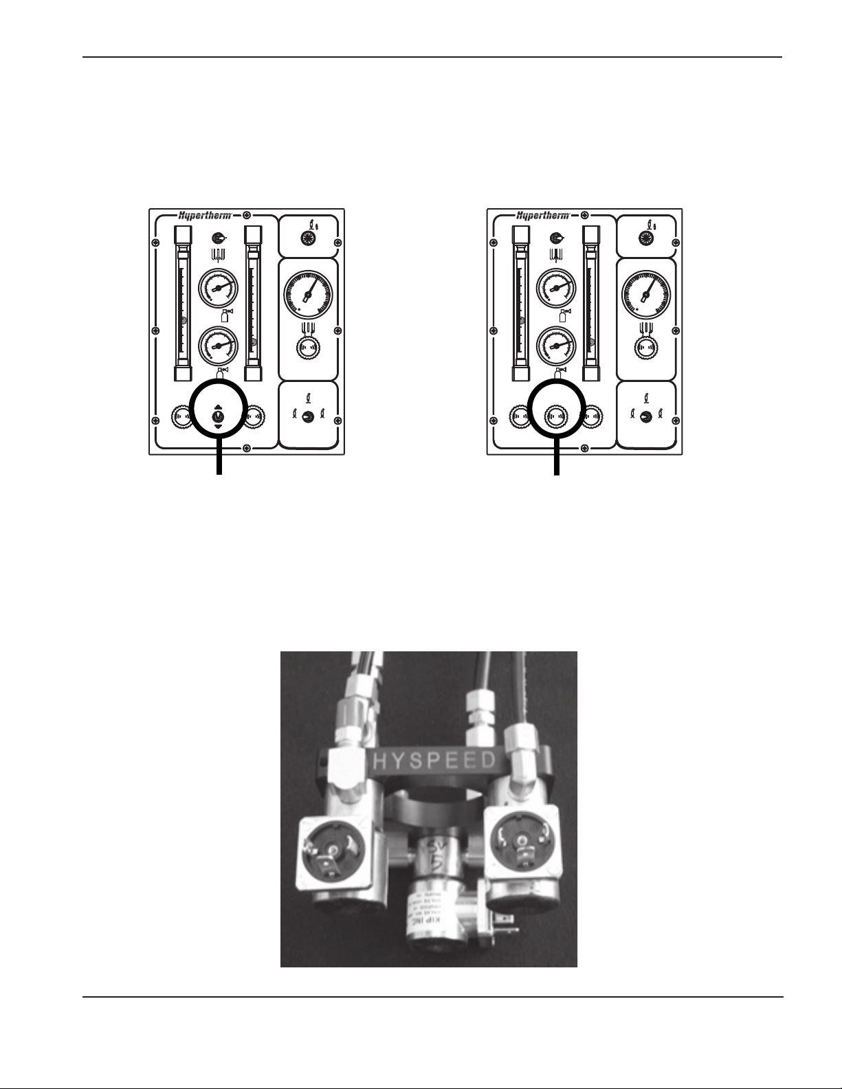
Before starting this upgrade you must determine if the system is a Local High Frequency (LHF) or a Remote High
Frequency system (RHF). You need to know this information to choose the correct firmware chip.
Inspect the gas console as described below:
1$LU
3/$60$
1
$LU
2
$LU
1
2
3/$60$
&XW)ORZ
SVL
SVL
2
3UH)ORZ3UH)ORZ
7HVW
3UHIORZ
'&
6+,(/'
SVL
5XQ
7HVW
&XWIORZ
If there is a toggle switch for the
plasma cutflow gas it is an RHF
system
If it has a knob to adjust the
plasma cutflow gas it is an LHF
system
1$LU
3/$60$
1
$LU
2
$LU
1
2
3/$60$
&XW)ORZ
SVL
SVL
2
3UH)ORZ3UH)ORZ
7HVW
3UHIORZ
'&
6+,(/'
SVL
5XQ
7HVW
&XWIORZ
The HySpeed off-valve assembly (129840) MUST be installed in an LHF system to continue with this upgrade. The offvalve assembly is marked HYSPEED, as shown below.
Field Service Bulletin 3
Page 6
HyPro2000 — HT2000 TORCH UPGRADE
Installation of the firmware chip
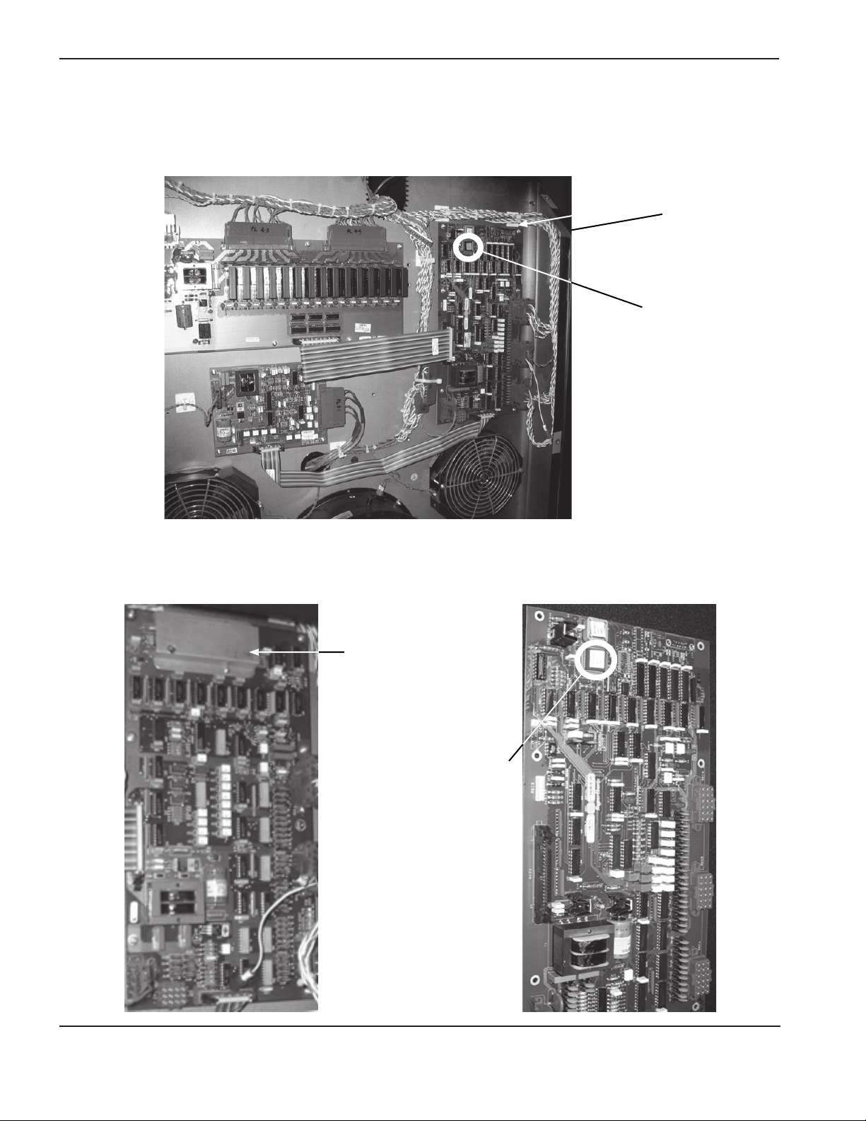
1. Access the control board (PCB2) by removing the 2 front panels. Inspect the control board. If it is a older
model, you will have to replace the board and the fi rmware chip.
Control board
location
Firmware chip
location
2. Inspect the control board. If it is a older model, you will have to replace the board and the fi rmware chip.
Older board
(replace board and chip)
Look for this
metal cover
ON the older
board
Firmware chip
location
Newer board
(replace chip)
4 Field Service Bulletin
Page 7
HyPro2000 — HT2000 TORCH UPGRADE
If you are installing a new control board skip to step 4.
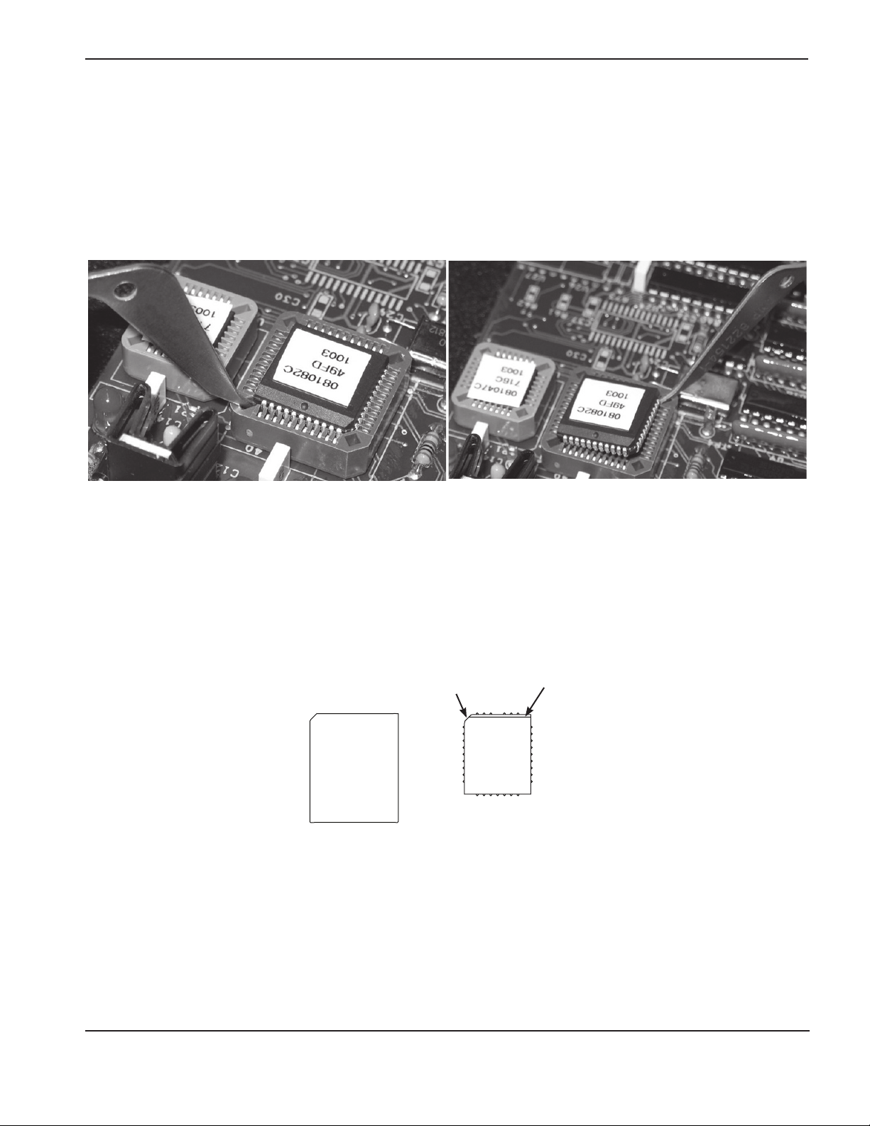
3. Remove and discard the old chip by using the tool included in this kit. See pictures below.
a. Place the straight end of the chip removal tool under one corner of the chip. Only 2 opposite corners will
accept the tool.
b. Carefully pry each of the 2 corners alternately until the chip is removed. Prying the chip out from only one
corner can damage the chip receptacle.
4. Chose the appropriate chip from fi rmware kit 228571 (located in the main kit box), and install it in the chip
receptacle on the control board.
Use the chip labeled 081192 for an RHF system.
Use the chip labeled 081194 for an LHF system.
Note: NOTE: The chip must be oriented correctly before installation. DO NOT use the orientation of the label to
orient the chip to the chip receptacle. There is a bevel on one edge of each chip and one corner is
angled (see fi gure below).
Angled corner
Firmware Chip
Chip receptacle
on PCB
Bevel
5. If you are installing a new control board see Installation of the new control board on the next page.
If you have installed the new chip on an existing control board see step 2 of Installation of the new control
board on the next page, before you replace the 2 front panels of the power supply and continue to torch and
quick-disconnect installation.
Field Service Bulletin 5
Page 8
HyPro2000 — HT2000 TORCH UPGRADE
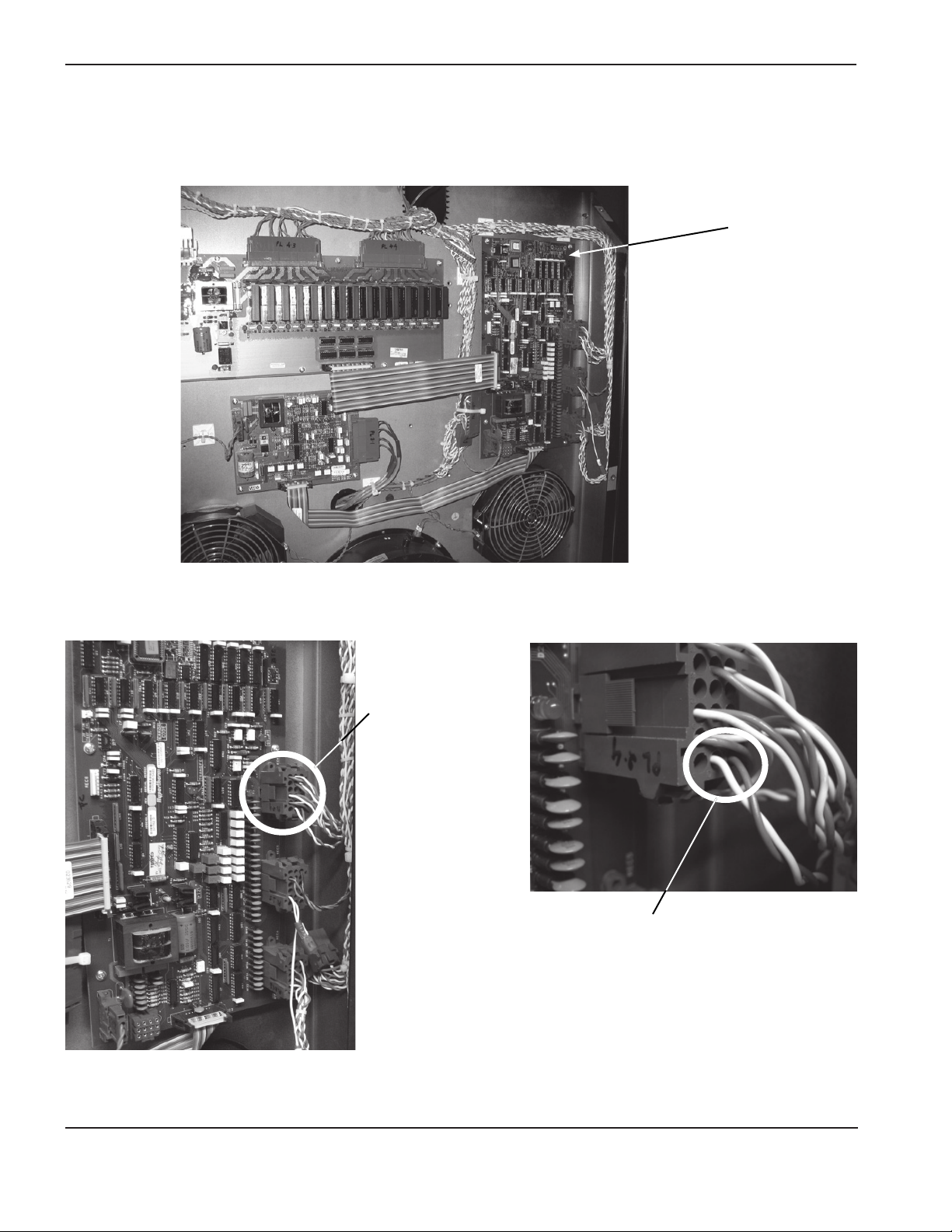
Installation of the new control board
1. Install the appropriate fi rmware chip on the new control board by following step 4 on the previous page.
Control board
location
2. Locate plug PL 2.4 in receptacle 4 on the control board. If no wires are present in sockets 1 and 2 use the
jumper wire provided in this kit to jump the 2 sockets.
Plug PL 2.4 in
receptacle 4
Wires (blue and white)
present in sockets 1 and 2
6 Field Service Bulletin
Page 9

HyPro2000 — HT2000 TORCH UPGRADE
3. Label each connector before removing any connections to the old board. After labeling the connectors,
remove all connections to the control board. Any wires that are present but not connected to the board will
remain disconnected.
4. Remove the 6 screws that hold the control board in place, and remove the old control board. Save the screws
for reuse.
5. Install the new control board using the six screws from step 3.
6. Plug all the connectors into the appropriate receptacles on the new control board.
7. Replace the 2 front panels and continue to torch and quick-disconnect installation.
Field Service Bulletin 7
Page 10
HyPro2000 — HT2000 TORCH UPGRADE
Torch and quick-disconnect receptacle Installation
1. Remove the existing torch and mounting sleeve from the lifter.
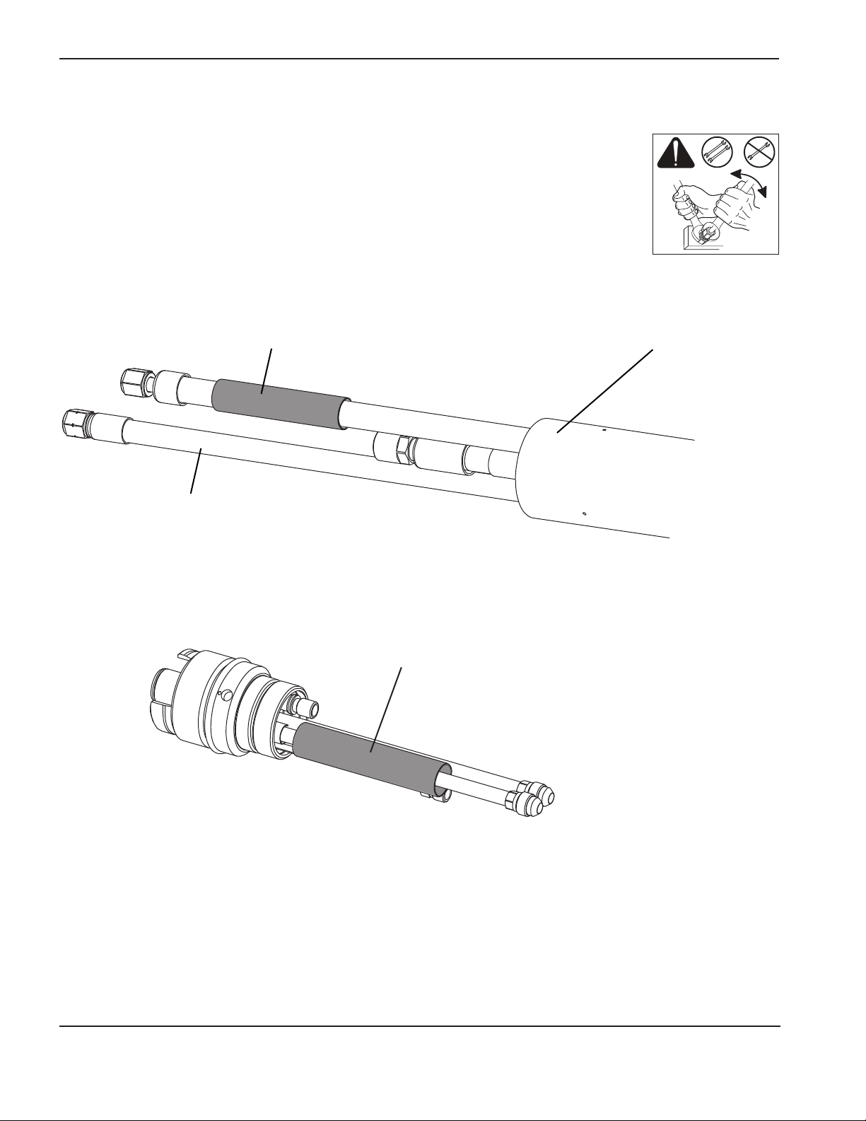
2. Unscrew the mounting sleeve and slide it up to expose the hose fi ttings.
3. Disconnect all the hoses and the pilot arc connection from the torch and remove the sleeve.
Always use 2 wrenches to loosen or tighten the fi ttings.
4. Inspect all hoses and wires for damage.
5. Loosen the off-valve assembly to remove the existing blue plasma hose.
6. Hold the black plasma hose provided in this kit with the bundled cables and hoses and slide the HyPro2000 torch
mounting sleeve over the leads (with the threaded end closest to the torch) and install the pilot arc lead insulator onto the
pilot arc lead (dark blue hose).
Pilot arc lead insulator Threaded end of the torch mounting sleeve
Black plasma gas hose
7. Connect the torch quick-disconnect receptakce to the torch leads.
a. The coolant hose insulator is on the coolant return (red) line of the torch quick disconnect when shipped.
Make sure it is in place before making any connections.
Coolant hose
insulator
8 Field Service Bulletin
Page 11
HyPro2000 — HT2000 TORCH UPGRADE
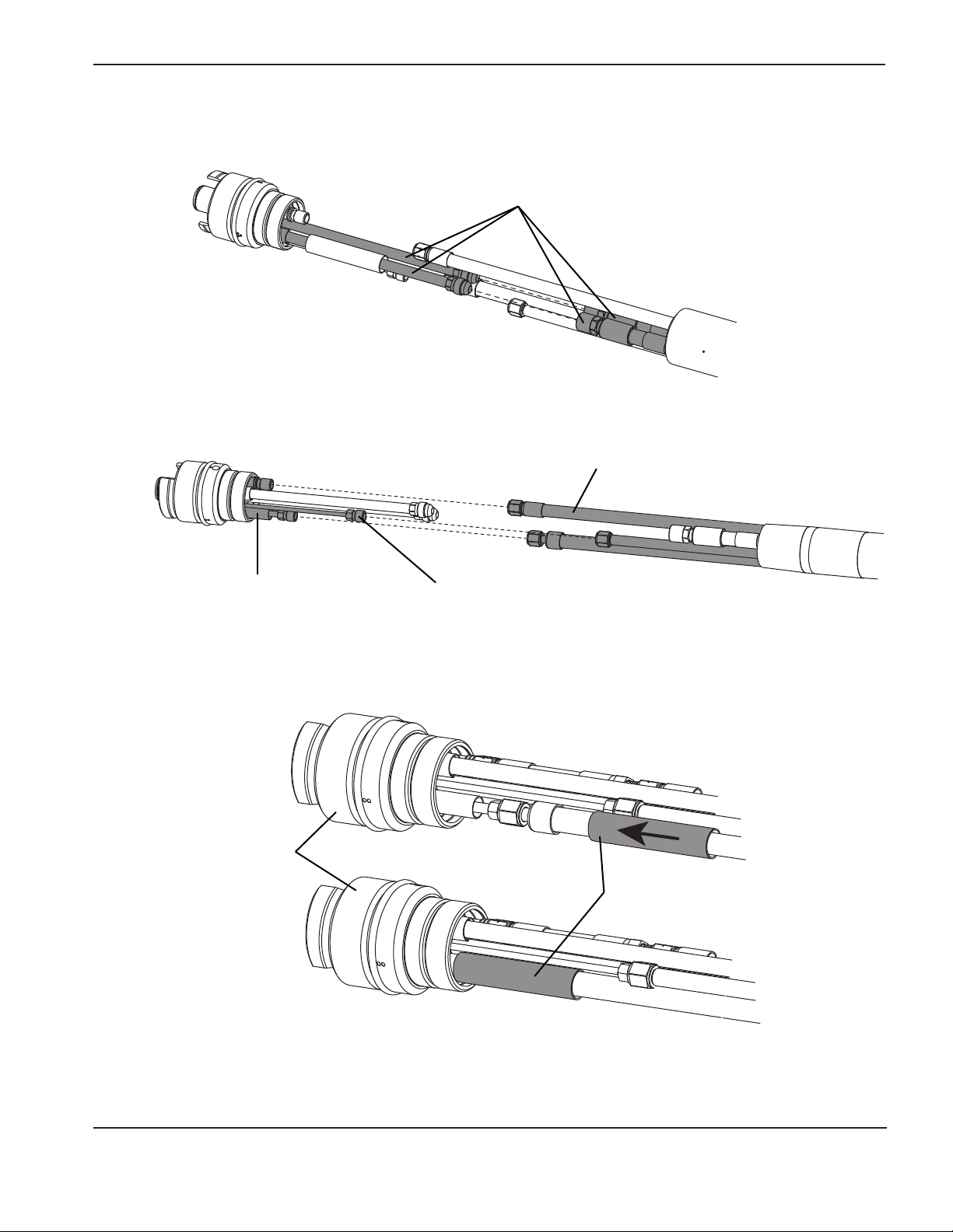
b. Connect the green and red coolant hoses to the fi tting on the torch quick-disconnect receptacle with the
corresponding color.
Coolant hoses
c. Connect the cap senor lead, the plasma gas hose, and the shield gas/pilot arc lead to the torch
quick-disconnect assembly.
Plasma gas hose
Cap sensor leadShield gas hose/pilot arc lead
8. Slide the pilot arc lead insulator over the blue shield gas/pilot arc lead until it contacts the bottom of the torch
quick-disconnect receptacle.
Torch
quick-disconnect
receptacle
Pilot arc lead insulator
Field Service Bulletin 9
Page 12

HyPro2000 — HT2000 TORCH UPGRADE
9. Slide the coolant hose insulator over the fi ttings.
10. Secure the coolant hose insulator in place by wrapping electrical tape around the lead set.
11. Slide the torch mounting sleeve over the fi ttings and screw it onto the torch quick-disconnect receptacle.
Torch mounting sleeve
10 Field Service Bulletin
Page 13

HyPro2000 — HT2000 TORCH UPGRADE
12. Install the pressure gauge included in this kit between the plasma gas line and the off-valve assembly.
Off-valve
connection
Plasma gas
hose connection
13. Install the torch onto the quick-disconnect receptacle.
a. Align any of the matching dots on the torch and quick-disconnect receptacle, and slide the torch into the
receptacle. 3 triangular dots are shown below, but there are also single dots that match and double dots
that match.
b. Turn the threaded collar on the torch clockwise until it is tight
Threaded collar
Alignment dots
Field Service Bulletin 11
Page 14

HyPro2000 — HT2000 TORCH UPGRADE
14. Verify gas pressures.
a. Turn on the power to the system and turn on the gas supplies.
b. Adjust the gas console settings for the chosen process using the cut charts in this document.
c. Verify the gas pressure reading on the gauge between the plasma gas line and the off-valve assembly with
the table below.
Note: Recommended incoming gas (supply gas) pressures are 120 psi for oxygen and nitrogen and 90 psi for air.
If the incoming gas pressure are not set correctly the back pressure reading will also
be incorrect.
15. Verify that there are no leaks at any of the connections.
16. Remove the pressure gauge that was installed in step 12 and the installation is complete.
Test pressures
Current Process
Amps Gases psi bar psi bar psi bar
50
Air/Air
Preflow pressure
(at the off-valve)
49.2 3.4 31.3 2.2 63.2 4.4
Cutflow pressure
(at the off-valve)
Pressure while cutting
(at the off-valve)
50
130
130 Air/Air 27 1.8 50 3.4 62.5 4.3
200
200
200 Air/Air 26 1.8 36 2.5 52 3.6
200 N2/Air 38.3 2.6 48.6 3.4 63.4 4.4
(SilverPlus electrode)
O2/Air
O2/Air
O2/Air
(copper electrode)
O2/Air
54.2 4.4 24.3 1.7 71 4.9
37.5 2.6 18.4 1.3 62.8 4.3
27 1.8 49 3.4 69 4.8
32 2.2 54 3.7 75 5.1
12 Field Service Bulletin
Page 15

HyPro2000 — HT2000 TORCH UPGRADE
Daily start-up
Prior to start-up, ensure that your cutting environment and that your clothing meet the safety requirements outlined in the
Safety section of the system’s instruction manual.
Check torch
WARNING
Before operating this system, you must read the Safety section thoroughly! Turn OFF the power
supply’s main disconnect switch before proceeding with the following steps.
1. Turn OFF the main disconnect switch to the power supply.
2. Remove the consumables from the torch and check for worn or damaged parts. Always place the
consumables on a clean, dry, oil-free surface after removing. Dirty consumables can cause the
torch tomalfunction.
• Refer to Install consumables on the next page for details.
• Refer to the Cut charts to choose the correct consumables for your cutting needs.
3. Replace consumable parts. Refer to Changing consumables later in this section for details.
4. Ensure that the torch is perpendicular to the workpiece.
Shield
Nozzle
retaining cap
Nozzle
Swirl ring
TorchWater tubeElectrode
Field Service Bulletin 13
Page 16

HyPro2000 — HT2000 TORCH UPGRADE
Install consumables
WARNING
Always disconnect power to the power supply before inspecting or changing torch consumable parts. Use gloves
when removing consumables. The torch might be hot.
Install consumables
Check the consumable parts daily for wear before cutting. Before removing consumables, bring the torch to the edge of
the cutting table, with the torch lifter raised to its highest point to prevent the consumables from dropping into the water
of the water table.
Note: Do not overtighten parts! Only tighten until mating parts are seated.
Apply a thin film of silicone
The o-ring should look shiny, but there should not be any excess or
built-up grease.
Tool: 104119
1. Install the
electrode
into the
torch head
lubricant on each o-ring.
2. Install the
swirl ring
into the
nozzle
3. Install the nozzle
and
swirl ring into the
nozzle
retaining cap
Wipe the internal and external surfaces of the
torch with a clean cloth or paper towel.
4. Install the
nozzle
retaining cap
onto the torch
head
5. Install the
shield onto
the nozzle
retaining cap
14 Field Service Bulletin
Page 17

HyPro2000 — HT2000 TORCH UPGRADE
Arc voltage
The arc voltage settings (v) shown in the cut charts may need to be adjusted to produce the correct cutting height.
Physically measuring the height after stopping the torch is preferred, but visual inspection during a cut is acceptable.
Over the life of a consumable set it will also be necessary to periodically adjust the arc voltage (v) up 1 to 2 volts at a
time to maintain the proper torch height and to achieve the maximum life from the consumables.
Cut charts
The following Cut charts show the consumable parts, cutting speeds, gas pressures, and the current settings required
for each process.
The numbers shown in the Cut charts are recommended to provide high-quality cuts with minimal dross. Because of
differences between installations and material composition, adjustments may be required to obtain desired results.
Digital remote
Hypertherm has produced a few versions of the digital remote. Some versions increase and decrease in 10 amp
increments, and some increase and decrease in 20 amp increments. If you have a digital remote that increases/
decreases by 20 amps, set the digital remote to 120 amps or 140 amps for a 130 amp process. The system will
automatically choose the 130 amp process.
Field Service Bulletin 15
Page 18

HyPro2000 — HT2000 TORCH UPGRADE
Estimated kerf width compensation
The widths in the chart below are for reference. Differences between installations and material composition may cause
actual results to vary from those shown in the tables.
Metric
Process Thickness (mm)
Mild steel 3468101215202532384450
50A O2/Air 1.5 1.6 –––––––––––
50A Air/Air 1.3 1.3 –––––––––––
130A O2/Air 2.4 2.5 2.7 2.8 2.9 3.1 3.3 3.6 4.0 – – – –
130A Air/Air 2.2 – 2.4 – 2.6 2.8 2.9 3.2 3.5 – – – –
200A O2/Air – – 2.8 2.9 3.0 3.3 3.4 3.7 4.1 4.6 5.0 5.4 5.9
200A Air/Air – – 2.7 – 2.9 3.1 3.4 3.6 4.0 4.5 5.0 – 5.9
Stainless steel
50A Air/Air 1.5 1.5 –––––––––––
200A N2/Air – – 2.5 2.6 2.7 2.9 3.1 3.3 3.7 4.1 4.5 – –
Aluminum
50A Air/Air 1.5 1.6 –––––––––––
200A N2/Air – – 3.2 3.3 3.4 3.6 3.8 4.1 4.6 5.1 5.6 – –
English
Process Thickness (in.)
Mild steel
50A O2/Air
50A Air/Air
130A O2/Air
130A Air/Air
200A O2/Air
200A Air/Air
Stainless steel
50A Air/Air 0.059 0.062 ––––––––
200A N2/Air – – 0.106 0.114 0.122 0.130 0.145 0.161 0.177 –
0.135 0.25 0.375 0.5 0.625 0.75 1.0 1.25 1.5 2.0
0.059 0.064 ––––––––
0.051 0.053 ––––––––
0.096 0.105 0.114 0.123 0.132 0.141 0.159 – – –
0.089 0.095 0.102 0.109 0.116 0.123 0.138 – – –
– 0.110 0.119 0.128 0.136 0.145 0.163 0.180 0.197 0.232
– 0.106 0.115 0.124 0.132 0.141 0.159 0.177 0.195 0.231
Aluminum
50A Air/Air 0.060 0.062 ––––––––
200A N2/Air – – 0.133 0.143 0.152 0.162 0.181 0.201 0.220 –
16 Field Service Bulletin
Page 19

HyPro2000 — HT2000 TORCH UPGRADE
Mild steel
Air Plasma / Air Shield
50 A Cutting
Flow rates – lpm/scfh
Preflow 123 / 259
Cutflow 114 / 241
220532 220528220529220890220936
220935
(No IHS tab)
Metric
Test Prefl ow
Flowrates
Prefl ow % Plasma % Shield (psi)
Air Air Air mm Volts mm mm/m mm factor % seconds
39 27 40
Test Cutfl ow
Flowrates
Material
Thickness
0.5 112 1.5 9400 3.0 200 0.0
0.8 111 1.5 8510 3.0 200 0.0
1.0 111 1.5 8050 3.0 200 0.1
1.2 107 1.8 7625 3.6 200 0.1
1.5 108 1.8 7370 3.6 200 0.1
2.0 108 1.8 6735 3.6 200 0.1
2.5 109 2.0 5080 4.0 200 0.2
3.0 112 2.0 3760 4.0 200 0.3
4.0 116 2.3 2415 4.6 200 0.4
6.0 120 2.5 1600 5.0 200 0.5
Arc
Voltage
Torch-to-Work
Distance
Cutting
Speed
Initial Pierce Height
Air
Pierce Delay
Time
English
Test Prefl ow
Flowrates
Prefl ow % Plasma % Shield (psi)
Air Air Air in Volts in ipm in factor % seconds
39 27 40
Test Cutfl ow
Flowrates
Material
Thickness
0.018 112 0.06 375 0.12 200 0.0
0.024 112 0.06 350 0.12 200 0.0
0.030 111 0.06 340 0.12 200 0.0
0.036 110 0.06 325 0.12 200 0.1
0.048 107 0.07 300 0.14 200 0.1
0.060 108 0.07 290 0.14 200 0.1
0.075 108 0.07 275 0.14 200 0.1
0.105 110 0.08 180 0.16 200 0.2
0.135 114 0.08 110 0.16 200 0.3
0.188 118 0.09 75 0.18 200 0.4
0.250 121 0.10 60 0.20 200 0.5
Arc
Voltage
Torch-to-Work
Distance
Cutting
Speed
Initial Pierce Height
Pierce Delay
Time
Field Service Bulletin 17
Page 20

HyPro2000 — HT2000 TORCH UPGRADE
O2 Plasma / Air Shield
220532 220528220529220891
220936
220935
(No IHS tab)
Metric
Test Prefl ow
Flowrates
Prefl ow % Plasma % Shield (psi)
O
2
N
2
35 0 21 30
Test Cutfl ow
Flowrates
O
2
Material
Thickness
Air mm Volts mm mm/m mm factor % seconds
0.5 98 1.5 7550 3.0 200 0.0
0.8 98 1.5 7050 3.0 200 0.0
1.0 98 1.5 6775 3.0 200 0.1
1.2 98 1.5 6600 3.0 200 0.1
1.5 98 1.5 6150 3.0 200 0.1
2.0 98 1.5 5400 3.0 200 0.1
2.5 100 1.8 4300 3.6 200 0.2
3.0 102 1.8 3650 3.6 200 0.3
4.0 104 2.0 2800 4.0 200 0.4
6.0 108 2.5 1750 4.0 200 0.5
Mild steel
50 A Cutting
Arc
Torch-to-Work
Voltage
Distance
Flow rates – lpm/scfh
O
Preflow 2 / 4 19 / 40 73 / 155
Cutflow 12 / 25 73 / 155
Cutting
Speed
Initial Pierce Height
2
N
2
Pierce Delay
Air
Time
English
Test Prefl ow
Flowrates
Prefl ow % Plasma % Shield (psi)
O
2
N
2
35 0 21 30
Test Cutfl ow
Flowrates
O
2
Material
Thickness
Air in Volts in ipm in factor % seconds
0.018 98 0.06 300 0.12 200 0.0
0.024 98 0.06 290 0.12 200 0.0
0.030 98 0.06 280 0.12 200 0.0
0.036 98 0.06 270 0.12 200 0.1
0.048 98 0.06 260 0.12 200 0.1
0.060 98 0.06 240 0.12 200 0.1
0.075 98 0.06 220 0.12 200 0.1
0.105 100 0.07 160 0.14 200 0.2
0.135 103 0.07 130 0.14 200 0.3
0.188 106 0.09 85 0.18 200 0.4
0.250 108 0.10 65 0.20 200 0.5
Arc
Voltage
Torch-to-Work
Distance
Cutting
Speed
Initial Pierce Height
Pierce Delay
Time
18 Field Service Bulletin
Page 21

HyPro2000 — HT2000 TORCH UPGRADE
O2 Plasma / Air Shield
220491 220488220893
220936
220935
(No IHS tab)
Metric
Test Prefl ow
Flowrates
Prefl ow % Plasma % Shield (psi)
O
2
N
2
25 30 34 35
Test Cutfl ow
Flowrates
O
2
Material
Thickness
Air mm Volts mm mm/m mm factor % seconds
3 128 2.6 5900 5.2 200 0.1
4 129 2.7 5325 5.4 200 0.2
6 129 2.8 3925 5.6 200 0.3
10 133 3.0 2680 6.0 200 0.4
12 135 3.0 2200 6.0 200 0.5
15 139 3.6 1665 7.2 200 0.7
20 141 3.9 1195 7.8 200 1.0
25 151 4.1 685 8.2 200 1.5
32 155 4.6 515
38 160 4.6 310
Mild steel
130 A Cutting
Arc
Torch-to-Work
Voltage
Distance
Flow rates – lpm/scfh
O
Preflow 16 / 33 21 / 44 86 / 183
Cutflow 20 / 42 86 / 183
2
N
220487
or
420185 SliverPlus
Cutting
Speed
Initial Pierce Height
Edge Start
2
Pierce Delay
Air
Time
English
Test Prefl ow
Flowrates
Prefl ow % Plasma % Shield (psi)
O
2
N
2
25 30 34 35
Test Cutfl ow
Flowrates
O
2
Material
Thickness
Air in Volts in ipm in factor % seconds
0.135 128 0.10 240 0.20 200 0.1
3/16 129 0.11 190 0.22 200 0.2
1/4 129 0.11 150 0.22 200 0.3
3/8 133 0.12 110 0.24 200 0.3
1/2 135 0.12 80 0.24 200 0.5
5/8 140 0.15 60 0.30 200 0.7
3/4 141 0.15 50 0.30 200 1.0
1.0 151 0.16 25 0.32 200 1.5
1-1/4 155 0.18 20
1-1/2 160 0.18 12
Arc
Voltage
Torch-to-Work
Distance
Cutting
Speed
Initial Pierce Height
Edge Start
Pierce Delay
Time
Field Service Bulletin 19
Page 22

HyPro2000 — HT2000 TORCH UPGRADE
Flow rates – lpm/scfh
Preflow 26 / 56 68 / 145
Cutflow 44 / 93 68 / 145
220536 220487220936
Mild steel
Air Plasma / Air Shield
130 A Cutting
220488220892
220935
(No IHS tab)
Metric
Test Prefl ow
Flowrates
Prefl ow % Plasma % Shield (psi)
Air Air Air mm Volts mm mm/m mm factor % seconds
45 77 24
Test Cutfl ow
Flowrates
Material
Thickness
3 139 3.0 5350 6.0 200 0.1
4 137 3.0 4630 6.0 200 0.2
6 142 3.4 3865 6.8 200 0.3
10 148 4.1 2445 8.2 200 0.5
12 149 4.1 2045 8.2 200 0.5
15 153 4.4 1445 8.8 200 0.8
20 159 4.6 815 10.5 230 1.2
25 167 4.6 415
32 174 5.1 250
Arc
Voltage
Torch-to-Work
Distance
Cutting
Speed
Initial Pierce Height
Edge Start
Air Air
Pierce Delay
Time
English
Test Prefl ow
Flowrates
Prefl ow % Plasma % Shield (psi)
Air Air Air in Volts in ipm in factor % seconds
45 77 24
Test Cutfl ow
Flowrates
Material
Thickness
0.135 140 0.12 220 0.24 200 0.1
3/16 136 0.12 160 0.24 200 0.2
1/4 144 0.14 150 0.28 200 0.3
3/8 148 0.16 100 0.32 200 0.5
1/2 149 0.16 75 0.32 200 0.5
5/8 154 0.18 50 0.36 200 0.8
3/4 158 0.18 35 0.42 230 1.2
1.0 167 0.18 15
1-1/4 174 0.20 10
Arc
Voltage
Torch-to-Work
Distance
Cutting
Speed
Initial Pierce Height
Edge Start
Pierce Delay
Time
20 Field Service Bulletin
Page 23

HyPro2000 — HT2000 TORCH UPGRADE
O2 Plasma / Air Shield
Copper electrode
220832 220937220834220831
220936
220935
(No IHS tab)
Metric
Test Prefl ow
Flowrates
Prefl ow % Plasma % Shield (psi)
O
2
N
2
12 38 70 53
Test Cutfl ow
Flowrates
O
2
Material
Thickness
Air mm Volts mm mm/m mm factor % seconds
6 145 1.5 6210 3.00 200 0.30
8 154 3.4 4850 5.10 150 0.35
10 160 4.6 3735 6.90 150 0.40
12 157 3.8 3415 9.50 250 0.60
15 156 3.1 2845 7.80 250 0.70
20 157 3.0 1920 7.50 250 0.80
25 163 3.2 1430 8.00 250 1.00
32 170 3.1 805 7.80 250 1.25
38 179 4.4 570 11.0 250 1.50
44 185 4.4 395
50 191 4.4 270
English
Test Prefl ow
Flowrates
Prefl ow % Plasma % Shield (psi)
O
2
N
2
12 38 70 53
Test Cutfl ow
Flowrates
O
2
Material
Thickness
Air in Volts in ipm in factor % seconds
1/4 147 0.075 235 0.150 200 0.30
3/8 161 0.188 150 0.280 150 0.30
1/2 156 0.140 130 0.280 200 0.30
5/8 156 0.115 105 0.280 250 0.50
3/4 157 0.115 80 0.280 250 0.60
7/8 162 0.125 65 0.312 250 0.70
1.0 163 0.125 55 0.312 250 0.80
1-1/4 170 0.125 32 0.312 250 1.25
1-1/2 179 0.175 22 0.437 250 1.50
1-3/4 185 0.175 15
2.0 192 0.175 10
Mild steel
200 A Cutting
Arc
Torch-to-Work
Voltage
Arc
Voltage
Distance
Torch-to-Work
Distance
Cutting
Speed
Cutting
Speed
Flow rates – lpm/scfh
O
Preflow 7 / 15 27 / 57 123 / 260
Cutflow 32 / 67 123 / 260
Initial Pierce Height
Initial Pierce Height
2
Edge Start
Edge Start
N
2
Pierce Delay
Air
Time
Pierce Delay
Time
Field Service Bulletin 21
Page 24

HyPro2000 — HT2000 TORCH UPGRADE
O2 Plasma / Air Shield
SilverPlus electrode
220832 220925220834220831
220936
220935
(No IHS tab)
Metric
Test Prefl ow
Flowrates
Prefl ow % Plasma % Shield (psi)
O
2
N
2
12 38 77 53
Test Cutfl ow
Flowrates
O
2
Material
Thickness
Air mm Volts mm mm/m mm factor % seconds
6 145 1.5 6210 3.0 200 0.30
8 154 3.4 4850 5.1 150 0.35
10 160 4.6 3735 6.9 150 0.40
12 157 3.8 3415 9.5 250 0.60
15 156 3.1 2845 7.8 250 0.70
20 158 3.0 1920 7.5 250 0.80
25 163 3.2 1430 8.0 250 1.00
32 170 3.1 805 7.8 250 1.25
38 179 4.4 565 11.0 250 1.50
44 185 4.4 395
50 191 4.4 270
Mild steel
200 A Cutting
Arc
Torch-to-Work
Voltage
Distance
Cutting
Speed
Flow rates – lpm/scfh
O
Preflow 7 / 15 27 / 57 123 / 260
Cutflow 34 / 72 123 / 260
Initial Pierce Height
2
Edge Start
N
2
Pierce Delay
Air
Time
English
Test Prefl ow
Flowrates
Prefl ow % Plasma % Shield (psi)
O
2
N
2
12 38 77 53
Test Cutfl ow
Flowrates
O
2
Material
Thickness
Air in Volts in ipm in factor % seconds
1/4 147 0.075 235 0.150 200 0.30
3/8 161 0.188 150 0.280 150 0.30
1/2 156 0.140 130 0.280 200 0.30
5/8 156 0.115 105 0.280 250 0.50
3/4 157 0.115 80 0.280 250 0.60
7/8 162 0.125 65 0.312 250 0.70
1.0 163 0.125 55 0.312 250 0.80
1-1/4 170 0.125 32 0.312 250 1.25
1-1/2 179 0.175 22 0.437 250 1.50
1-3/4 185 0.175 15
2.0 192 0.175 10
Arc
Voltage
Torch-to-Work
Distance
Cutting
Speed
Initial Pierce Height
Edge Start
Pierce Delay
Time
22 Field Service Bulletin
Page 25

HyPro2000 — HT2000 TORCH UPGRADE
Mild steel
Air Plasma / Air Shield
200 A Cutting
420045 220937220488420044
220936
Flow rates – lpm/scfh
Preflow 26 / 56 123 / 220
Cutflow 31 / 65 123 / 220
220935
(No IHS tab)
Metric
Test Prefl ow
Flowrates
Prefl ow % Plasma % Shield (psi)
Air Air Air mm Volts mm mm/m mm factor % seconds
45 57 44
Test Cutfl ow
Flowrates
Material
Thickness
6 134 1.0 4885 3.0 300 0.3
8 138 1.3 4515 3.9 300 0.5
10 142 2.6 2975 5.2 200 0.8
12 145 3.0 2655 6.0 200 0.9
15 152 4.3 2265 8.6 200 1.0
20 160 4.8 1415 9.6 200 1.1
25 165 6.4 940 12.8 200 1.2
32 172 6.4 630 12.8 200 1.8
38 176 6.4 510
50 186 6.4 215
Arc
Voltage
Torch-to-Work
Distance
Cutting
Speed
Initial Pierce Height
Edge Start44 180 6.4 320
Air Air
Pierce Delay
Time
English
Test Prefl ow
Flowrates
Prefl ow % Plasma % Shield (psi)
Air Air Air in Volts in ipm in factor % seconds
45 57 44
Test Cutfl ow
Flowrates
Material
Thickness
1/4 134 0.040 190 0.120 300 0.3
5/16 138 0.050 180 0.150 300 0.5
3/8 142 0.100 120 0.200 200 0.8
1/2 145 0.125 100 0.250 200 0.9
5/8 152 0.188 85 0.375 200 1.0
3/4 155 0.188 60 0.375 200 1.1
7/8 160 0.188 50 0.375 200 1.2
1.0 165 0.250 35 0.500 200 1.2
1-1/4 172 0.250 25 0.500 200 1.8
1-1/2 176 0.250 20
2.0 186 0.250 8
Arc
Voltage
Torch-to-Work
Distance
Cutting
Speed
Initial Pierce Height
Edge Start1-3/4 180 0.250 12
Pierce Delay
Time
Field Service Bulletin 23
Page 26

HyPro2000 — HT2000 TORCH UPGRADE
Mild steel – 3 inch under water
O2 Plasma / Air Shield
Copper electrode
220832 220937220834220831
Metric
Test Prefl ow
Flowrates
Prefl ow % Plasma % Shield (psi)
O
2
N
2
O
12 38 70 53
220936
220935
(No IHS tab)
Test Cutfl ow
Flowrates
2
Material
Thickness
Air mm Volts mm mm/m mm factor % seconds
6 142 0.7 6235 1.4 200 0.3
10 166 3.8 3460 7.6 200 0.3
12 159 2.9 3060 5.8 200 0.3
15 159 2.8 2555 5.6 200 0.5
20 163 3.0 1700 7.5 250 0.6
22 164 3.2 1545 8.0 250 0.7
25 165 3.2 1300 8.0 250 0.8
200 A Cutting
Arc
Torch-to-Work
Voltage
Distance
Cutting
Speed
Flow rates – lpm/scfh
O
Preflow 7 / 15 27 / 57 123 / 260
Cutflow 32 / 67 123 / 260
Initial Pierce Height
2
N
2
Pierce Delay
Air
Time
English
Test Prefl ow
Flowrates
Prefl ow % Plasma % Shield (psi)
O
2
N
2
12 38 70 53
Test Cutfl ow
Flowrates
O
2
Material
Thickness
Air in Volts in ipm in factor % seconds
1/4 145 0.040 235 0.080 200 0.3
3/8 168 0.157 140 0.312 200 0.3
1/2 157 0.100 115 0.200 200 0.3
5/8 160 0.115 95 0.230 200 0.5
3/4 163 0.115 70 0.290 250 0.6
7/8 164 0.125 60 0.312 250 0.7
1.0 165 0.125 50 0.312 250 0.8
Arc
Voltage
Torch-to-Work
Distance
Cutting
Speed
Initial Pierce Height
Pierce Delay
Time
24 Field Service Bulletin
Page 27

HyPro2000 — HT2000 TORCH UPGRADE
Mild steel – 3 inch under water
O2 Plasma / Air Shield
SilverPlus electrode
220832 220925220834220831
Metric
Test Prefl ow
Flowrates
Prefl ow % Plasma % Shield (psi)
O
2
N
2
O
12 38 77 53
220936
220935
(No IHS tab)
Test Cutfl ow
Flowrates
2
Material
Thickness
Air mm Volts mm mm/m mm factor % seconds
6 142 0.7 6235 1.4 200 0.3
10 166 3.8 3460 7.6 200 0.3
12 159 2.9 3060 5.8 200 0.3
15 159 2.8 2555 5.6 200 0.5
20 163 3.0 1700 7.5 250 0.6
22 164 3.2 1545 8.0 250 0.7
25 165 3.2 1300 8.0 250 0.8
200 A Cutting
Arc
Torch-to-Work
Voltage
Distance
Cutting
Speed
Flow rates – lpm/scfh
O
Preflow 7 / 15 27 / 57 123 / 260
Cutflow 34 / 72 123 / 260
Initial Pierce Height
2
N
2
Pierce Delay
Air
Time
English
Test Prefl ow
Flowrates
Prefl ow % Plasma % Shield (psi)
O
2
N
2
12 38 77 53
Test Cutfl ow
Flowrates
O
2
Material
Thickness
Air in Volts in ipm in factor % seconds
1/4 145 0.040 235 0.080 200 0.3
3/8 168 0.157 140 0.312 200 0.3
1/2 157 0.100 115 0.200 200 0.3
5/8 160 0.115 95 0.230 200 0.5
3/4 163 0.115 70 0.290 250 0.6
7/8 164 0.125 60 0.312 250 0.7
1.0 165 0.125 50 0.312 250 0.8
Arc
Voltage
Torch-to-Work
Distance
Cutting
Speed
Initial Pierce Height
Pierce Delay
Time
Field Service Bulletin 25
Page 28

HyPro2000 — HT2000 TORCH UPGRADE
Stainless steel
Air Plasma / Air Shield
50 A Cutting
220532 220528220529220890
220936
Flow rates – lpm/scfh
Preflow 123 / 259
Cutflow 114 / 241
220935
(No IHS tab)
Metric
Test Prefl ow
Flowrates
Prefl ow % Plasma % Shield (psi)
Air Air Air mm Volts mm mm/m mm factor % seconds
39 27 40
Test Cutfl ow
Flowrates
Material
Thickness
0.5 103 1.5 7620 3.0 200 0.0
0.8 104 1.5 6730 3.0 200 0.0
1.0 104 1.5 6350 3.0 200 0.1
1.2 105 1.8 5715 3.6 200 0.1
1.5 108 1.8 4830 3.6 200 0.1
2.0 110 1.8 4190 3.6 200 0.1
2.5 113 2.0 3175 4.0 200 0.2
3.0 114 2.0 2160 4.0 200 0.3
4.0 118 2.3 1400 4.6 200 0.4
6.0 122 2.5 1145 5.0 200 0.5
Arc
Voltage
Torch-to-Work
Distance
Cutting
Speed
Initial Pierce Height
Air
Pierce Delay
Time
English
Test Prefl ow
Flowrates
Prefl ow % Plasma % Shield (psi)
Air Air Air in Volts in ipm in factor % seconds
39 27 40
Test Cutfl ow
Flowrates
Material
Thickness
0.018 103 0.06 300 0.12 200 0.0
0.024 103 0.06 275 0.12 200 0.0
0.030 104 0.06 265 0.12 200 0.0
0.036 104 0.06 250 0.12 200 0.1
0.048 105 0.07 225 0.14 200 0.1
0.060 108 0.07 190 0.14 200 0.1
0.075 109 0.07 165 0.14 200 0.1
0.105 114 0.08 125 0.16 200 0.2
0.135 115 0.08 85 0.16 200 0.3
0.188 121 0.09 55 0.18 200 0.4
0.250 122 0.10 45 0.20 200 0.5
Arc
Voltage
Torch-to-Work
Distance
Cutting
Speed
Initial Pierce Height
Pierce Delay
Time
26 Field Service Bulletin
Page 29

HyPro2000 — HT2000 TORCH UPGRADE
Flow rates – lpm/scfh
Preflow 26 / 56 68 / 145
Cutflow 44 / 93 68 / 145
220536 220487220936
Stainless steel
Air Plasma / Air Shield
130 A Cutting
220488220892
220935
(No IHS tab)
Metric
Test Prefl ow
Flowrates
Prefl ow % Plasma % Shield (psi)
Air Air Air mm Volts mm mm/m mm factor % seconds
45 77 24
Test Cutfl ow
Flowrates
Material
Thickness
6 142 3.5 2625 7.0 200 0.3
10 149 4.1 1700 8.2 200 0.5
12 152 4.1 1380 8.2 200 0.8
15 160 4.4 900
20 165 4.6 430
Arc
Voltage
Torch-to-Work
Distance
Cutting
Speed
Initial Pierce Height
Edge Start
Air Air
Pierce Delay
Time
English
Test Prefl ow
Flowrates
Prefl ow % Plasma % Shield (psi)
Air Air Air in Volts in ipm in factor % seconds
45 77 24
Test Cutfl ow
Flowrates
Material
Thickness
1/4 143 0.14 100 0.28 200 0.3
3/8 148 0.16 70 0.32 200 0.5
1/2 153 0.16 50 0.32 200 0.8
5/8 162 0.18 30
3/4 164 0.18 20
Arc
Voltage
Torch-to-Work
Distance
Cutting
Speed
Initial Pierce Height
Edge Start
Pierce Delay
Time
Field Service Bulletin 27
Page 30

HyPro2000 — HT2000 TORCH UPGRADE
Flow rates – lpm/scfh
Preflow 26 / 56 123 / 220
Cutflow 31 / 65 123 / 220
420045 220937220936
Stainless steel
Air Plasma / Air Shield
200 A Cutting
220488420044
220935
(No IHS tab)
Metric
Test Prefl ow
Flowrates
Prefl ow % Plasma % Shield (psi)
Air Air Air mm Volts mm mm/m mm factor % seconds
45 57 44
Test Cutfl ow
Flowrates
Material
Thickness
5 140 2.7 5695 5.4 200 0.40
6 144 3.0 3105 6.0 200 0.40
10 144 3.2 2485 6.4 200 0.50
12 147 3.2 2245 6.4 200 0.75
15 152 3.8 1700 7.6 200 0.80
20 156 4.9 1155 9.8 200 1.00
25 162 5.6 670
38 180 5.6 310
Arc
Voltage
Torch-to-Work
Distance
Cutting
Speed
Initial Pierce Height
Edge Start32 172 5.6 515
Air Air
Pierce Delay
Time
English
Test Prefl ow
Flowrates
Prefl ow % Plasma % Shield (psi)
Air Air Air in Volts in ipm in factor % seconds
45 57 44
Test Cutfl ow
Flowrates
Material
Thickness
3/16 140 0.110 230 0.22 200 0.40
1/4 144 0.120 200 0.24 200 0.40
3/8 144 0.125 160 0.25 200 0.50
1/2 147 0.125 110 0.25 200 0.75
5/8 152 0.157 85 0.315 200 0.80
3/4 156 0.188 60 0.375 200 1.00
7/8 160 0.210 50 0.420 200 1.20
1.0 162 0.220 40
1-1/2 180 0.220 12
Arc
Voltage
Torch-to-Work
Distance
Cutting
Speed
Initial Pierce Height
Edge Start1-1/4 172 0.220 20
Pierce Delay
Time
28 Field Service Bulletin
Page 31

HyPro2000 — HT2000 TORCH UPGRADE
420045 020415220936
220935
(No IHS tab)
Metric
Test Prefl ow
Flowrates
Prefl ow % Plasma % Shield (psi)
N
2
Test Cutfl ow
Flowrates
N
2
45 55 44
Stainless steel
N2 Plasma / Air Shield
200 A Cutting
Flow rates – lpm/scfh
N
Preflow 26 / 56 123 / 220
Cutflow 31 / 65 123 / 220
2
220529420044
Material
Thickness
Air mm Volts mm mm/m mm factor % seconds
5 154 3.0 3505 6.0 200 0.40
6 155 3.0 3355 6.0 200 0.40
10 156 3.0 2670 6.0 200 0.50
12 158 3.0 2210 6.0 200 0.75
15 160 4.0 1930 8.0 200 0.80
20 162 4.8 1180 9.6 200 1.00
22 167 4.8 1035 9.6 200 1.20
25 172 6.2 890 12.4 200 1.30
32 180 6.2 610
38 188 6.2 380
Arc
Voltage
Torch-to-Work
Distance
Cutting
Speed
Initial Pierce Height
Edge Start
Pierce Delay
Time
Air
English
Test Prefl ow
Flowrates
Prefl ow % Plasma % Shield (psi)
N
2
45 55 44
Test Cutfl ow
Flowrates
N
2
Material
Thickness
Air in Volts in ipm in factor % seconds
3/16 154 0.125 230 0.25 200 0.40
1/4 155 0.125 200 0.25 200 0.40
3/8 156 0.125 160 0.25 200 0.50
1/2 158 0.125 110 0.25 200 0.75
5/8 160 0.157 75 0.315 200 0.80
3/4 162 0.188 60 0.375 200 1.00
7/8 167 0.188 40 0.375 200 1.20
1.0 172 0.250 35 0.50 200 1.30
1-1/4 180 0.250 25
1-1/2 188 0.250 15
Arc
Voltage
Torch-to-Work
Distance
Cutting
Speed
Initial Pierce Height
Edge Start
Pierce Delay
Time
Field Service Bulletin 29
Page 32

HyPro2000 — HT2000 TORCH UPGRADE
Aluminum
Air Plasma / Air Shield
50 A Cutting
220532 220528220529220890
220936
Flow rates – lpm/scfh
Preflow 123 / 259
Cutflow 114 / 241
220935
(No IHS tab)
Metric
Test Prefl ow
Flowrates
Prefl ow % Plasma % Shield (psi)
Air Air Air mm Volts mm mm/m mm factor % seconds
39 27 40
Test Cutfl ow
Flowrates
Material
Thickness
0.5 110 1.5 8000 3.0 200 0.0
0.8 111 1.6 7750 3.2 200 0.0
1.0 112 1.8 7115 3.6 200 0.1
1.2 112 1.8 6350 3.6 200 0.1
1.5 113 1.8 5335 3.6 200 0.1
2.0 118 2.0 4200 4.0 200 0.1
2.5 121 2.0 3300 4.0 200 0.2
3.0 122 2.0 2800 4.0 200 0.3
4.0 123 2.2 2300 4.4 200 0.4
6.0 128 2.5 1400 5.0 200 0.5
Arc
Voltage
Torch-to-Work
Distance
Cutting
Speed
Initial Pierce Height
Air
Pierce Delay
Time
English
Test Prefl ow
Flowrates
Prefl ow % Plasma % Shield (psi)
Air Air Air in Volts in ipm in factor % seconds
39 27 40
Test Cutfl ow
Flowrates
Material
Thickness
0.018 110 0.06 325 0.12 200 0.0
0.020 110 0.06 315 0.12 200 0.0
0.024 110 0.06 305 0.12 200 0.0
0.030 111 0.06 295 0.12 200 0.1
0.036 112 0.07 280 0.14 200 0.1
0.048 112 0.07 230 0.14 200 0.2
0.060 113 0.07 195 0.14 200 0.2
0.075 118 0.08 160 0.16 200 0.2
0.105 121 0.08 120 0.16 200 0.3
0.125 122 0.08 100 0.16 200 0.3
3/16 124 0.09 75 0.18 200 0.4
1/4 129 0.10 50 0.20 200 0.5
Arc
Voltage
Torch-to-Work
Distance
Cutting
Speed
Initial Pierce Height
Pierce Delay
Time
30 Field Service Bulletin
Page 33

HyPro2000 — HT2000 TORCH UPGRADE
Flow rates – lpm/scfh
Preflow 26 / 56 68 / 145
Cutflow 44 / 93 68 / 145
220536 220487220936
Aluminum
Air Plasma / Air Shield
130 A Cutting
220488220892
220935
(No IHS tab)
Metric
Test Prefl ow
Flowrates
Prefl ow % Plasma % Shield (psi)
Air Air Air mm Volts mm mm/m mm factor % seconds
45 77 24
Test Cutfl ow
Flowrates
Material
Thickness
6 152 2.8 2370 5.6 200 0.2
10 155 3.0 1470 6.0 200 0.3
12 157 3.0 1230 6.0 200 0.5
15 161 3.2 1050 6.4 200 0.8
20 164 3.6 725 7.9 220 1.3
25 172 4.0 525 Edge Start
Arc
Voltage
Torch-to-Work
Distance
Cutting
Speed
Initial Pierce Height
Air Air
Pierce Delay
Time
English
Test Prefl ow
Flowrates
Prefl ow % Plasma % Shield (psi)
Air Air Air in Volts in ipm in factor % seconds
45 77 24
Test Cutfl ow
Flowrates
Material
Thickness
1/4 152 0.11 90 0.22 200 0.2
3/8 155 0.12 60 0.24 200 0.3
1/2 157 0.12 45 0.24 200 0.5
5/8 162 0.13 40 0.26 200 0.8
3/4 163 0.14 30 0.31 220 1.3
1.0 173 0.16 20 Edge Start
Arc
Voltage
Torch-to-Work
Distance
Cutting
Speed
Initial Pierce Height
Pierce Delay
Time
Field Service Bulletin 31
Page 34

HyPro2000 — HT2000 TORCH UPGRADE
Flow rates – lpm/scfh
Preflow 26 / 56 123 / 220
Cutflow 31 / 65 123 / 220
420045 220937220936
Aluminum
Air Plasma / Air Shield
200 A Cutting
220488420044
220935
(No IHS tab)
Metric
Test Prefl ow
Flowrates
Prefl ow % Plasma % Shield (psi)
Air Air Air mm Volts mm mm/m mm factor % seconds
45 57 44
Test Cutfl ow
Flowrates
Material
Thickness
5 145 2.2 6215 4.4 200 0.5
6 148 3.0 5195 6.0 200 0.5
10 151 3.3 3930 6.6 200 0.5
12 154 3.7 3370 7.4 200 0.5
15 157 4.0 2625 8.0 200 0.8
20 161 4.9 1625 9.8 200 1.0
25 174 5.6 1050
38 196 5.6 310
Arc
Voltage
Torch-to-Work
Distance
Cutting
Speed
Initial Pierce Height
Edge Start32 186 5.6 515
Air Air
Pierce Delay
Time
English
Test Prefl ow
Flowrates
Prefl ow % Plasma % Shield (psi)
Air Air Air in Volts in ipm in factor % seconds
45 57 44
Test Cutfl ow
Flowrates
Material
Thickness
3/16 145 0.100 230 0.200 200 0.50
1/4 148 0.125 200 0.250 200 0.50
3/8 151 0.125 160 0.250 200 0.50
1/2 154 0.150 125 0.300 200 0.50
5/8 157 0.160 95 0.320 200 0.80
3/4 161 0.188 70 0.375 200 1.00
7/8 166 0.210 50 0.420 200 1.20
1.0 174 0.220 40
1-1/2 196 0.220 12
Arc
Voltage
Torch-to-Work
Distance
Cutting
Speed
Initial Pierce Height
Edge Start1-1/4 186 0.220 20
Pierce Delay
Time
32 Field Service Bulletin
Page 35

HyPro2000 — HT2000 TORCH UPGRADE
420045 020415220936
(No IHS tab)
Metric
Test Prefl ow
Flowrates
Prefl ow % Plasma % Shield (psi)
N
2
Test Cutfl ow
Flowrates
N
2
45 55 44
Aluminum
N2 Plasma / Air Shield
200 A Cutting
Flow rates – lpm/scfh
N
Preflow 26 / 56 123 / 220
Cutflow 31 / 65 123 / 220
2
220529420044
220935
Material
Thickness
Air mm Volts mm mm/m mm factor % seconds
5 150 2.2 4750 4.4 200 0.5
6 153 3.0 4345 6.0 200 0.5
10 156 3.3 3050 6.6 200 0.5
12 159 3.7 2490 7.4 200 0.5
15 165 4.0 2010 8.0 200 0.8
20 170 4.9 1450 9.8 200 1.0
22 176 5.6 1295 11.2 200 1.2
25 184 5.6 1040
38 200 5.6 510
Arc
Voltage
Torch-to-Work
Distance
Cutting
Speed
Initial Pierce Height
Edge Start32 194 5.6 740
Pierce Delay
Time
Air
English
Test Prefl ow
Flowrates
Prefl ow % Plasma % Shield (psi)
N
2
45 55 44
Test Cutfl ow
Flowrates
N
2
Material
Thickness
Air in Volts in ipm in factor % seconds
3/16 150 0.125 190 0.25 200 0.5
1/4 153 0.125 200 0.25 200 0.5
3/8 156 0.125 160 0.25 200 0.5
1/2 159 0.125 125 0.25 200 0.5
5/8 165 0.157 95 0.314 200 0.8
3/4 170 0.188 70 0.375 200 1.0
7/8 176 0.250 50 0.50 200 1.2
1.0 184 0.250 40
1-1/2 200 0.250 12
Arc
Voltage
Torch-to-Work
Distance
Cutting
Speed
Initial Pierce Height
Edge Start1-1/4 194 0.250 20
Pierce Delay
Time
Field Service Bulletin 33
Page 36

HyPro2000 — HT2000 TORCH UPGRADE
34 Field Service Bulletin
 Loading...