

Page 1
Instruction Manual
Original instructions
808310 | Revision 0 | English
Page 2

Instruction Manual
808310 – Revision 0
English
March 2014
Hypertherm Inc.
Hanover, NH 03755 USA
Page 3

1 Introduction ........................................................................................................................... 3
1.1 Company Overview and Contact Information ................................................................................. 3
1.2 System Overview ............................................................................................................................. 3
1.3 Definitions ....................................................................................................................................... 4
2 Safety....................................................................................................................................... 5
2.1 General Safety .................................................................................................................................. 5
2.2 Safety Symbols ................................................................................................................................ 5
2.3 Operation and Maintenance Safety .................................................................................................. 6
2.4 Emergency Medical Treatment ........................................................................................................ 9
3 Installation ............................................................................................................................ 11
3.1 Installation Overview ..................................................................................................................... 11
3.2 Utility Requirements ...................................................................................................................... 11
4 Operation .............................................................................................................................. 15
4.1 Operation Overview ....................................................................................................................... 15
4.2 Front Control Panel ........................................................................................................................ 15
4.3 Pump Startup .................................................................................................................................. 17
4.4 Pump Operation ............................................................................................................................. 19
5 Electrical System .................................................................................................................. 23
5.1 Electrical System Overview ........................................................................................................... 23
5.2 Electrical Control Panel ................................................................................................................. 23
5.3 Motors ............................................................................................................................................ 27
5.4 System Fault Detection .................................................................................................................. 29
6 Low-Pressure Water ............................................................................................................ 33
6.1 Low-Pressure Water Overview ...................................................................................................... 33
6.2 Inlet Cutting Water Supply ............................................................................................................ 33
6.3 Cooling Water Loop (Not all Models) ........................................................................................... 36
7 High-Pressure Water ........................................................................................................... 37
7.1 High-Pressure Water Overview ..................................................................................................... 37
7.2 Intensifier ....................................................................................................................................... 38
7.3 High-Pressure Ends ........................................................................................................................ 38
7.4 Check Valve Assembly .................................................................................................................. 41
7.5 Hydraulic Seal Housing ................................................................................................................. 44
7.6 Hydraulic Center Section ............................................................................................................... 45
7.7 Intensifier Cycling ......................................................................................................................... 47
7.8 Pump Bleed-Down Valve .............................................................................................................. 48
7.9 Attenuator ...................................................................................................................................... 49
7.10 High-Pressure Filter Assembly (Optional) ................................................................................ 49
7.11 High-Pressure Plumbing Weep Holes ....................................................................................... 50
8 Hydraulic .............................................................................................................................. 51
8.1 Hydraulic Oil ................................................................................................................................. 51
8.2 Control Manifold ........................................................................................................................... 53
8.3 Oil Filter ......................................................................................................................................... 54
8.4 Heat Exchanger .............................................................................................................................. 54
1
Page 4

8.5 Hydraulic Tank .............................................................................................................................. 55
8.6 Main Pump Setup ........................................................................................................................... 55
9 Specifications ........................................................................................................................ 57
9.1 Pump Requirements ....................................................................................................................... 57
9.2 Pump Capabilities .......................................................................................................................... 60
9.3 Orifice Combinations ..................................................................................................................... 60
9.4 Inlet Cutting Water Requirements ................................................................................................. 60
9.5 Water Treatment Guidelines: ......................................................................................................... 61
9.6 Torque Specifications .................................................................................................................... 62
10 Maintenance and Troubleshooting ................................................................................ 63
10.1 Parts and Service Contact Information ...................................................................................... 63
10.2 Maintenance Guidelines ............................................................................................................ 63
10.3 Troubleshooting ......................................................................................................................... 65
10.4 Maintenance Log ....................................................................................................................... 69
11 Document Revisions ........................................................................................................ 71
12 Drawings and Parts Lists ............................................................................................... 73
13 Controls Manual ............................................................................................................. 75
2
Page 5

1 Introduction
1.1 Company Overview and Contact Information
Our Mission
To contribute to the waterjet community through the engineering, manufacturing, and sale of high
quality waterjet products that lower the operating cost as an alternative to costly laser and plasma
cutting.
We take pride in being a company that is recognized for its honesty, integrity, and personal service.
We strive for the greatest reliability and quality in our products and technical support.
The Company
Hypertherm is a waterjet supply company with a history of providing economical solutions for a broad
range of customers through the engineering, manufacturing, and sale of quality products and parts.
Hypertherm's rapid shift to the forefront of the waterjet industry can be attributed to our product
reliability and an unyielding focus on customer feedback and support. Hypertherm has quickly earned a
reputation for superior customer satisfaction and unparalleled service from a well-trained customer and
technical support staff.
History
Hypertherm's background in waterjets started in the mid-1980s with the development, application, and
sale of waterjet products for a major equipment manufacturer. In the late 1990s Hypertherm was started
with the goal of supplying quality spare parts and innovative products to help waterjet users lower their
operating cost. Today, the company has become the leading source for industrial waterjet products.
Customer & Technical Servic e
At Hypertherm, your purchase is only the beginning of our commitment to help you succeed. We
believe that what happens after the sale is just as important as what happens before.
Customer Service Representatives are avai lab le to tak e your calls Monday throu g h Friday 8:00 AM to
5:00 PM CST. If you need service after-hours Hypertherm is also on-call 24 hours a day, 7 days a week
to ensure your system is up and running around the clock.
For more information, please call Customer Service toll-free at 800-991-4225.
1.2 System Overview
Introduction
Pump Identification Form
Hypertherm SERIAL NUMBER ____________________________________________
For additional copies of this manual and/or other assistance, please contact:
Hypertherm, Inc.
309 5th Ave NW
New Brighton, MN 55112
+1 800-991-4225
3
Page 6

1.3 Definitions
LP water: Low-pressure water that is supplied to the intensifier for pressurizing.
HP water: High-pressure water that is directed to the tool after being pressurized by the intensifier
assembly.
Coolant water: Water that is circulated through the heat exchanger for cooling the hydraulic fluid.
Pump: A HyPrecision pump.
ID: Inside diameter.
RPC: Remote Pump Control allows operation of the pump from a remote control source.
OCS: Operator Control Station.
4
Page 7
2 Safety
2.1 General Safety
This section describes the hazards specifically related to the operation and maintenance of HyPrecision
100D/150D Intensifier Pumps. These precautions must be reviewed and understood by operating and
maintenance personnel before installing, operating or servicing the equipment.
The comprehensive list of safety precautions listed in this manual must be followed to ensure safe
operation of the equipment. The safety guidelines found in this manual are general and cannot cover
every possible situation; only thorough knowledge of the equipment can provide optimum safety.
Readers are expected to know how to use common hand tools safely, as well as the basic techniques for
safe operation of pressure-producing equipment.
Always remember that the waterjet stream is a cutting tool! The force of a waterjet
can penetrate and cut through almost any material.
WARNING
ervice procedures in this manual will include safety warnings, cautions, and notes that must be read
S
and understood.
The following symbols are used throughout the manual to bring the reader's attention to known hazards
and conditions, which can be avoided. Although an attempt to point out most conditions was made,
Hypertherm acknowledges tha t there are other unforeseen situations due to site variability, improper
maintenance, etc. that could also potentially cause equipment damage, severe injury, or death. It is the
end user’s responsibility to identify these additional hazards and take necessary steps to minimize risks.
2.2 Safety Symbols
Warnings, cautions, and notes
Always avoid contact with the stream of water. Abrasive waterjets expel a mixtur e
of water and abrasive that, if contact is made with skin, may be injected into the
skin leading to a serious infection. Seek immediate surgical attention if you
WARNING
WARNING
CAUTION
encounter any high-pressure stream of fluid.
Indicates the presence of a hazard, which can cause severe personal injury,
death, and/or substantial property damage if the warning instructio n is ignored.
Highlights important instructions, which must be followed to prevent personal
injury and/or equipment damage.
5
Page 8
IMPORTANT
Hazardous voltage within can cause injury or death. Disconnect and lock out main
Draws attention to items of important factual or procedural significance. Failure to
follow the instructions may result in equipment damage.
power before opening the cabinet.
High-pressure waterjet can cause eye injury. Wear eye protection when operating
or working near the machine.
Wear ear protection when operating or working near the machine to reduce the
risk of hearing loss.
Airborne contaminants or suspended particles may exist when cutting certain
materials. Wear respiratory protection when these conditions are present.
2.3 Operation and Maintenance Safety
Read and understand the Operation section of this manual before operating the equipment. People who
have not been trained in the safe operation of this waterjet machine should not be allowed near the
system.
• Always wear safety glasses when working on or near the pum
• Clean and inspect equipment regularly and fix all problems immediately.
• The operation and maintenance of this system should only be performed by trained, qualified
personnel.
• Ensure that all personnel not involved in operating the machine are a safe distance from the
equipment.
• Keep the work area clean and free of water or fluid spills.
Operating Safety
Failure to wear proper safety gear can result in personal injury or death. Safety shoes, hardhat, hearing
protection, and other personal protective equipment are strongly recommended.
High-pressure waterjet can cause eye injury. Wear eye protection when operating
or working near the machine.
p.
Wear ear protection when operating or working near the machine to reduce the
risk of hearing loss.
6
Page 9
Airborne contaminants or suspended particles may exist when cutting certain
ause injury or death. Disconnect and lock out main
materials. Wear respiratory protection when these conditions are present.
Maintenance Safety
• Read the instructions in all sections of this manual before performing any maintenance on the
pump. Important information is contained throughout this manual to minimize hazards and wear
t
he machine.
Before starting any ser vice or maintenance, turn off electrical power and relieve
all water and hydraulic pressure. Proper lockout/tag-out procedures must always
be followed prior to performing any maintenance of the unit.
WARNING
• Use the proper too ls requ ir e d for speci fic pro cedu res. When special tools are called for, make sure
t
o use them because they are specifically designed to make the job easier and prevent damage to th
e
quipment
• R
emove all tools from the work area before starting the machine.
.
• Always test the pump after service or maintenance: follow startup procedures outlined in the
Operation section of this manual.
Electrical System Safety
on
e
• Always make certain the electrical current is shut off a nd the proper lock o ut/t ag-out procedures
have been followed before starting any service or maintenance procedures.
Hazardous voltage within can c
power before opening the cabinet.
• Make sure that all safety devices are operational.
• To panic-stop the pump and bleed the high pressure, push in the EMERGENCY STOP button.
• Open the main power circuit breaker (plant-supplied power) before beginning the procedure. Attach
a safety tag warning others not to turn the power o
• W
hen replacing wiring, use only the same size, type, and color as the original
fter servicing, ensure all electrical breakers are reconnected and doors and covers are closed
• A
n.
.
before restarting.
• To check emergency system: turn on power and push the EMERGENCY STOP button(s). Chec
he system to make sure it has been shut down properly.
t
k
7
Page 10

High-Pressure Water System Safety
Never work on any high-pressure component or loosen any high-pressure fittings without first bleeding
the system to ensure that there is no high-pressure water present. Follow all instructions and safety
recommendations in this manual.
Always avoid contact with the stream of water. Seek immediate surgical attention
if you are exposed to any high-pressure stream of fluid.
WARNING
• Avoid contact with the high-pressure water. HP water can penetrate any part of the human body and
cau
se severe infection or death if not treated properly. Seek immediate surgical attention if y
c
ome in contact with any high pressure stream of fluid.
• Do not try to repair a leak on any HP water fitting when the system is pressurized. A leak at
seal
ing surface can cause a hazardous spray of water. Shut off the motor and verify the HP water
pressure is relieved down the drain before servicing any high-pressure plumbing.
• Plumbing supports and guides must be used for all HP tubing exiting the pump. Failure to do so ca
introduce excessive bending stress and fatigue through vibration causing premature failure of the
plumbing, and heighten risk of personal injury due to an unexpected rupture.
• Always use two wrenches when tightening or loosening HP connections: one for the gland nut and
for the fitting. This will prevent excessive bending stress and premature failure of th
one
pl
umbing.
• Always use high-pressure piping rated for the type of system you are operating. This pump is
capable of outputting 60,000 psi of water.
ou
a
e
n
Hydraulic System Safety
Pressurized fluid streams can penetrate skin, causing severe personal injury or
death. If any fluid is ejected against the skin, seek immediate surgical attention.
WARNING
• Make sure all connections are properly tightened after performing service or maintenance.
• Keep hands and body away from pinholes and nozzles, which eject fluids under high pressure
ever check for hydraulic leaks with your hand: use a piece of cardboard or other material.
• N
• Do not expose skin to a pressurized leak.
• Wear appropriate protective equipment including heavy gloves and safety glasses.
• Do not attempt to tighten or loosen any mechanical connection unless the machine is powered off
and all system pressure has been relieved.
.
8
Page 11

Motor/Pump Assembly Safety
Beware of moving equipment. Keep clothing and hands away from equipment that
is operating. Always verify covers and shields are in place before starting
equipment.
WARNING
2.4 Emergency Medical Treatment
Waterjet equipment can cause severe injury and infection. Anytime a person comes in contact with a
high pressure stream of fluid, it must be reported immediately and treated. It may look as though
nothing happened, but a serious infection and possible amputation may result if immediate surgical
attention is not received.
Always seek immediate surgical attention if you come in contact with any high pressure stream of fluid.
Failure to do so can result in severe infection.
The injury should be treated as an acute surgical emergency and be evaluated by a qualified surgeon.
Circulation may be compromised therefore DO NOT apply heat. K eep effec ted pe rson awak e and
elevate injured part.
Inform the medical personnel that the victim has been working with a high-pressure mixture of water
and abrasives at up to 60,000 psi and a nozzle velocity of up to 2,000 feet per second. Waterjet injuries
have been known to cause infections with micro-Europhilic organisms such as gram-negative pathogens
like those found in sewage.
9
Page 12

Emergency me dic al in f ormation
MEDICAL ALERT
Anyone who receives equipment related injuries while operating high-pressure water equipment
should be given immediate hospital attention. It is vital that waterjet operators carry a waterproof
emergency medical tag or card that describes their work and the nature of injuries inherent in using
waterjet cutting devices.
This card provides general purpose information to aid in relaying information to medical or emergency
personnel.
This card is to be carried by personnel working
with high-pressure waterjet equipm ent . Obtain
medical treatment immediately for ANY highpressure waterjet injuries.
Hypertherm Inc.
309 5th Ave NW
New Brighton, MN 55112
+1 651-294-8600
This person has been working with water jetting at pressures to
60,000- psi (4,137bar) with a jet velocity of 2000fps (610 mps).
This should be taken into account during diagnosis. Unusual
infections with microaerophilic organisms occu r ring at lower
temperatures have been reported. These may be gram-negative
pathogens, such as those found in sewage. Bacterial swabs and
blood cultures may therefore be helpful. A local poison control
center should be contacted for additional treatment information.
10
Page 13

3 Installation
3.1 Installation Overview
Buyer Obligations
The buyer of a HyPrecision 100D/150D waterjet pump is responsible to cooperate with Hypertherm and
Hypertherm OEM personnel to facilitate installation of the machine.
• The pump should be uncrated and placed as close as possible to the position where it will be used.
• All utilities must be provided prior to installation as o utl in ed in th e Specifications section of this
manual.
• The buyer should install high-pressure tubing unless other arrangements have been made in th
sal
es agreement.
• Water treatment equipment should be in place prior to the installation of the pump. Water must
meet the minimum requirements as outlined in the Specifications section of this manual.
• All connections to the pump are the responsibility of the buyer. It is the buyer's responsibility to
esearch and comply with all local codes including wastewater disposal.
r
Hypertherm may or may not supply the pump without any hydraulic oil in the tank. It may be the
buyer's responsibility to fill the tank with the appropriate oil per instructions in the Hydraulic section of
this manual.
Seller Obligations
e
• If Hypertherm, Inc. is the installing party, some or all of the following tasks will be the
responsibility of the Hypertherm techn ician at ins talla ti on as defined in the sal es ag reement.
• Make sure the buyer has been informed of all buyer obligations and make sure the site has been
properly prepared prior to installation.
• Make sure all utility connections have been properly provided as outlined in the Specifications
section of this manual.
• Follow all first time startup and setup instructions as provided in the Operations section of thi
m
anual.
• Train maintenance personnel on proper service and repair procedures.
• Follow sta nda rd sy stem acceptan ce tes ts.
3.2 Utility Requirements
Site Preparation
Certain locations may be hazardous if the atmosphere contains gas, vapors, or
dust in explosive quantities. Refer to the National Electric Code (NEC), IEC, OSHA
requirements, and local codes for detailed information about environmental
WARNING
The facility must have adequate air, water, sewer drain, and electrical service per the Specifications
section prior to installation of the equipment.
Floor material should be concrete capable of supporting the weight of the machine, and thick enough to
provide resistance to vibration.
criteria.
s
11
Page 14

Water Requirements
flow prevention valve be supplied to separate
Local codes may require that a backthe pump from the building potable water. Consult local codes for the required
type and necessity of a valve.
IMPORTANT
Cutting Water
The water supplied to the intensifier is a crucial factor in precision waterjet cutting because of its direct
effect on the service life of equipment components. The pump's built-in filtration is sufficient for
removal of suspended solids. Total Dissolved Solids (TDS) in the inlet water will have an adverse effect
on check valves, seals, orifices, and other consumables. Most systems require that the water be softened
at a minimum before it enters the pump.
Before installing the system have a water quality analysis performed by a local company that can
provide water-conditioning equipment. See the Inlet Cutting Water Requirements section under
Specifications for specific conditioning requirements.
Cooling Water (if supplied with a Water/Oil Heat Exchanger)
The heat exchanger uses regular tap water for cooling the hydraulic fluid. Hydraulic fluid temperature
must be maintained below 130ºF. The hydraulic cooling water section of the Specifications area of
this manual details the cooling water flow and temperature requirements.
In most cases public-utility water is acceptable. In situations where the water contains heavy mineral
deposits, the cooling fins in the heat exchanger may become clogged with buildup. In these
circumstances pre-filtration and/or softening may be necessary. Depending on plant setup, ambient
temperature can also be a factor in cooling. Where the equipment is confined to a small hightemperature space, additional cooling may be required.
Sewer Requirements
The pump has two outlet lines. The WASTE WATER OUT line carries any rejected cut water from the
bleed-down valve. The COOLING OUT line carries the water exiting the heat exchanger in water
cooling units. DO NOT couple lines.
Both outlets require independent lines to the sewer drain to prevent exiting cooling water from backing
up into the system. The wastewater outlet plumbing must be lower than the outlet connection on the
pump. This will prevent potentially dirty water from backing into the bleed down valve causing closure
problems.
12
Page 15
Electrical Requirements
WARNING
When connecting power to the pump it is the buyer's responsibility to investigate
and comply with all local codes. The power requirements are listed on the serial
plate on the back of the pump as well as on the inside of the electrical enclosure
CAUTION
door.
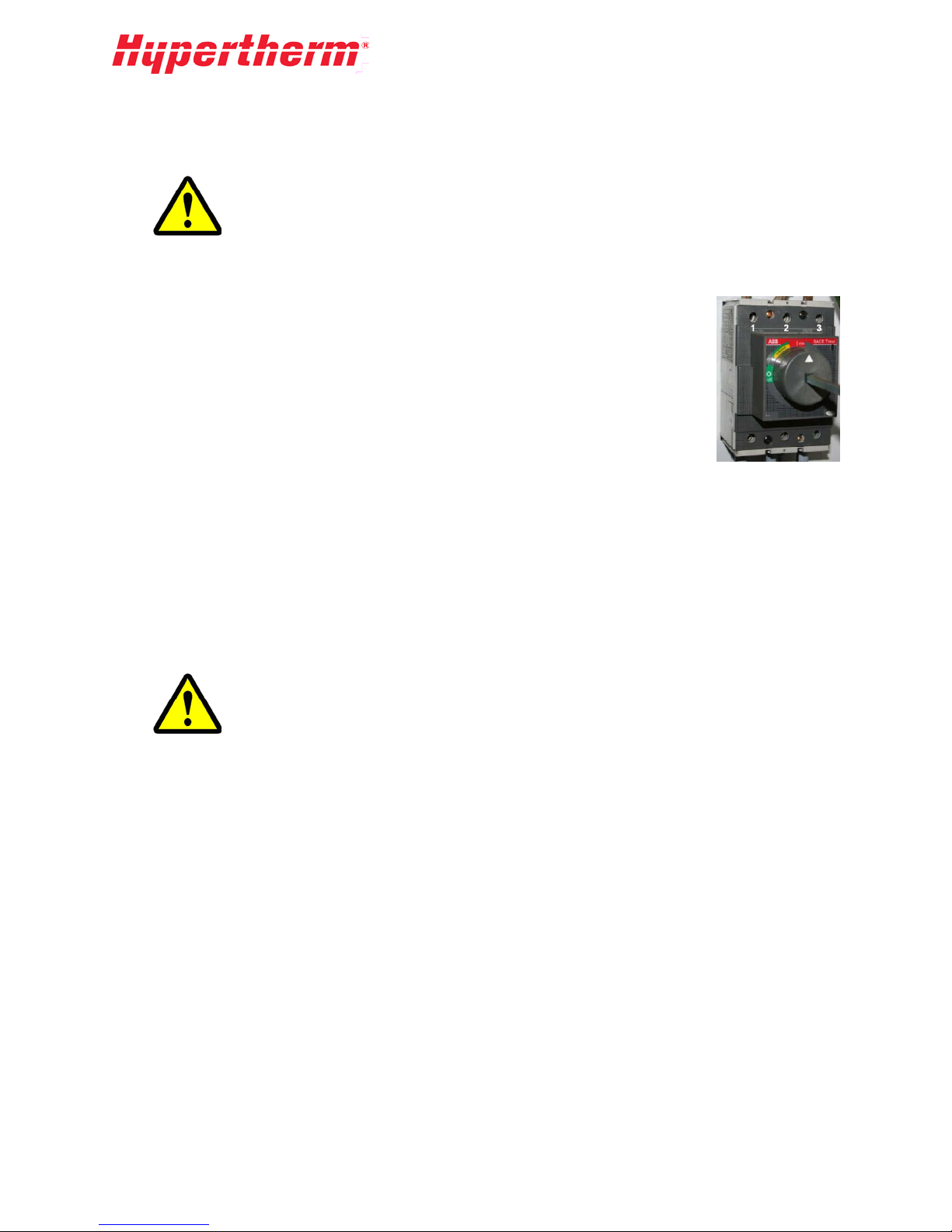
Three phase power connection
Each of the three phases of input power are connected t o the three (3) terminals at
the top of the motor switch (right). Additionally a ground leg must be attached to
the grounding lug inside the electrical cabinet.
Pumps equipped for certain foreign power may have slightly different connection
requirements. Always refer to the electrical schematic for the machine to verify
proper connection.
Schematics are supplied in the Drawing s and Part s Lists section of the manual and
an additional copy is included inside the electrical cabinet.
Location Requirements
• The pump must be placed in a location, which allows access to all sides for service.
• The pump should have a minimum 36 in. clearance surrounding the machine, free of all obstacles,
to allow room for service. See the Pump Requirements section under Specifications
• The pump should not be placed in any environment where the temperature is below freezing. If
freezing temperatures are expected before operating again, drain all water lines and filter housings
after work is completed for the day.
.
If a water line, fitting, or valve may be frozen, DO NOT operate the machine. The
system must be thawed until water flows freely through the entire water circuit.
Recommended Tools
Most maintenance of the pump can be accomplished using standard tools. Re fe r to the recomm ended
tools list in the Drawings and Parts Lists section. Contact Hypertherm to purchase replacement
specialty tools for intensifier and bleed-down valve servicing.
13
Page 16

14
Page 17
4 Operation
4.1 Operation Overview
This section outlines the operation of the Front Control Panel, as well as startup procedures, and normal
operation. The HyPrecision 100D/150D pumps are controlled from the front control panel.
The main disconnect on the electrical enclosure must be turned on in order for the pump to function.
4.2 Front Control Panel
The HyPrecision 100D/150D pumps are controlled via an Operator Control Station (OCS) attached to
the outside of the Electrical enclosure. The OCS monitors all fault conditions and controls the
intensification process. Certain pump models referred to as OEM may not have a control panel. In this
case, refer to the manual for the equipment that is controlling the pump.
The OCS is equipped with digital inputs and outputs for monitoring all pump and environmental
conditions as well as controlling the functions of the pump.
Other features include intensif ier enabl e/d isa ble, intensifier-overstroke threshold setup, and alarm
logging.
Log files are stored on a removable MicroSD card. When troubleshooting is necessary, the card can be
removed from the pump and the information transferred via a USB reader to Hypertherm technicians.
Program updates can also be installed by simply copying a new program onto the card and replacing it
in the pump.
No service is necessary on the OCS. All inputs and outputs run to terminal blocks, which should be used
for wiring the remote options. Refer to the supplemental control manual, for additional details about
control operation and features.
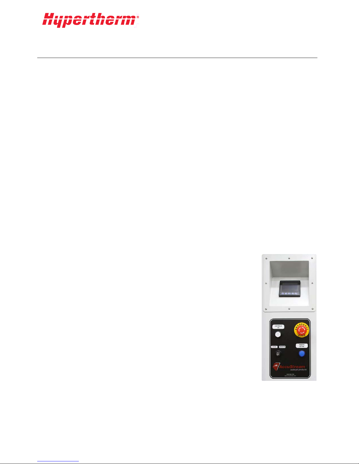
Standard Control P anel
Base model pumps have the standard control panel. The standard control panel
has an OCS panel, hydraulic gauge, cut pressure adjustment knob, and pierce
pressure adjustment knob. In addition, there are water gauges indicating the pre
and post filter water pressure.
The following image shows the standard control panel (all HyPrecision
100D/150D models).
CONTROLS ON: Enables the pump controls.
LOCAL/REMOTE KEYSWITCH: Switches from local pump control to
remote pump control. See Remot e Pump Operation under the Operation
section in this manual.
EMERGENCY STOP: Shuts off controls, motors, and intensifiers, and bleeds
down the high-pressure water.
REMOTE ACTIVE light: Lit when pump is in remote pump control mode or
remote pressure control mode.
15
Page 18

Depending on the type of pump model(s) you have the layout of the gauge panel will vary.
The PIERCE PRESSURE and CUT PRESSURE adjustment knobs, located on the gauge panel, are
manually operated.
Units with the optional analog pressure control will not have the CUT PRESSURE and PIERCE
PRESSURE control knobs, which are replaced with a high precision electrical control valve.
CUT PRESSURE knob (if applicable): Adjusts Pressure Set Point 1 (Cut). See Adjusting the Cut and
Pierce Pressure in the Operation section for more information.
PIERCE PRESSURE knob (if applicable): Adjusts Pressure Set Point 2 (Pierce). See Adjusting the
Cut and Pierce Pressure in the Operation section for more information.
HYDRAULIC PRESSURE gauge: Displays the hydraulic pressure of the pump. Pumps with more
than one hydraulic pump will have additional gauges. The hydraulic pressure gauge can be useful in
determining the approximate cut pressure. To do so, use the following formula:
Cut Pressure = 19.25 X Hydraulic Pressure
PRE-FILTER WATER PRESSURE gauge: Displays the water pressure before the filter bank. See
the Low-Pressure Water section of this manual for more information.
Normal operating range: 40-110PSI
POST-FILTER WATER PRESSURE gauge: Displays the water pressure after the filter bank. See the
Low-Pressure Water section of this manual for more information.
Normal operating range: 40-110PSI
50S 60S 75S
16
Page 19

4.3 Pump Startup
Initial or Post-Maintenance Startup
The first time you start up your pump it is important that the Pre-Startup Inspection, Motor Direction
Check, and First Tim e Sta rt up procedures (below) be performed to prevent serious damage to the pump
components. Make sure that all installation requirements have been met prior to performing any of the
following checks. Follow all safety procedures as outlined in the Safety section of this manual.
It is common to identify leaks in the high-pressure water, low-pressure water, and possibly hydraulic
circuits while performing these procedures. Always stop the procedure and correct the leaks before
continuing.
Pre-Startup Inspection
1. Verify all safety circuits are connected and operational.
2. Check the sight gauge to make sure the hydraulic reservoir is full. Add oil as necessary to bring
the oil to an acceptable level. Refer to Hydraulic Oil in the Hydraulic section in this manual for
instructions on adding oil.
3. Verify all utilities are connected to the pump and turned on at the plant.
4. Check for loose hoses and fittings and make sure there are no leaks present.
Motor Direction Check
This procedure involves exposing a rotating shaft. Never place any object or any
part of your body near the shaft while exposed. Only visual inspection should be
used to prevent bodily injury. Be prepared to press the EMERGENCY STOP
CAUTION
IMPORTANT
button.
The motor direction check should be performed anytime electrical maintenance
has been performed on the electrical panel, motor wiring, or line wiring to the
pump. Improper motor rotation can cause irreversible damage to the hydraulic
pump and components.
1. Open or remove the front cover from the pump and locate the motor rotation arrow.
2. Remove the safety cover on the pump mount and visually inspect the coupling rotation.
3. To jog the motor, pull the EMERGENCY STOP button on the control panel, and then press the
CONTROLS ON button.
4. Press
(COOLING MODE) and then press ( PU MP OFF) to jog the motor. Verify
visually that the shaft is rotating the same way the motor rotation arrow indicates.
If the motor rotates in the wrong direction, swap two of the wires at the starter panel's MAIN
DISCONNECT, not at the motor or starter contactors, and then recheck the rotation. After verifying
motor rotation, replace the safety cover on the pump mount and the side covers. Also, see Motors in the
Electrical System section for additional information.
17
Page 20

First Time Startup
The following first time startup procedure should be followed after any service has
been performed on the intensifier,
assemblies.
high-pressure water, or low-pressure water
IMPORTANT
1. Make sure the cut pressure and pierce pressure adjustment knobs are backed out all the way. If
the pump has analog pressure control make sure the pressure setting is 10ksi or less.
The pump may have been shipped with loose fittings, filters, and components
depending on winterization requirements, where the pump is shipped to, and
other environmental factors. Make sure that all of the water fittings and loose
components are tightened before proceeding to the next step.
2. Prime the flow of the cutting water:
a. Disable the Intensifier.
b. Open the cutting head.
c. Turn the source water on.
d. Let sit for 2-3 minutes
epress the red button on the top of each of the filter housings to bleed air from the canisters.
e. D
f. Close the cutting head.
.
3. Start the pump by pressing the
t
hat the boost pressure meets the inlet water requirements as outlined in the Specifications
(PUMP ON) button on the touchscreen display. Make sure
section of this manual.
4. Check again for any leaks and loose fittings. Take any corrective action and then proceed to the
next step.
5. Flush the pump and high-pressure lines using the following procedure.
Flushing HP Water Lines
After installation of a new pump and high-pressure lines, it is common for small pieces of metal and
debris to be present in the high-pressure lines.
NEVER perform the initial startup with a diamond orifice in place. The likelihood of
damaging the orifice during the initial startup is very high!
IMPORTANT
It is important to flush the system to prevent damage to orifices, on/off valve
parts, and other parts of the HP system.
The following procedure describes one method to “flush out” the HP lines. If you purchased your
Hypertherm pump through an OEM, they may have their own procedure that they recommend. During
this procedure, damage may occur to the on/off valve sealing parts and orifices. Make sure to have spare
kits and orifices available before starting the procedure.
18
Page 21

This flushing procedure should be followed after any replacement or service to the high-pressure lines
and fittings have been performed on the pump.
1. Make sure the pierce pressure control knob is backed out all the way, and the pump pressure is set
to 10ksi or less. See Adjusting the Pump Pressure in the Operation section for more
information.
2. Remove the cutting head and orifice leaving just the on/off valve body and adapter.
3. Set the pump pressure to 20ksi (approximately 1000 psi hydraulic) using the pump compensator
S
ee Adjusting the Pump Pressure in the Operation section for more information.
4. If possible, use your CNC control to make a program that will turn on and off the valve in onesecond increments and run the program in a loop for 15 minutes. This will shock the HP tubing
and free any debris present in the lines.
Any debris that breaks can cause damage to your on/off valve needle and seat. If
this happens, try to complete this procedure by removing all debris from the
components rather than replacing the parts right away.
5. Replace the sapphire orifice in the cutting head with one that is appropriately sized for your
pump.
6. Set the pump pressure to 40ksi (approximately 2000 psi hydraulic) and repeat the program
(above) for another 15 minutes.
7. Turn the pressure up to 60ksi (3000 hydraulic) and repeat the program again for 15 minutes.
8. If necessary, replace the on/off valve needle, seat, and seals as well as any damaged orifices.
.
Normal Startup Procedure
1. Verify all safety circuits are connected and operational.
2. Check the sight gauge to make sure the hydraulic reservoir is full. Add oil as necessary to bring
the oil to an acceptable level. Refer to Hydraulic Oil in the Hydraulic section of this manual
for instructions on adding oil.
3. Verify all utilities are connected to the pump and turned on at the plant.
4. Check for loose hoses and fittings and make sure there are no leaks present.
5. Press
start generating pressure at the Pressure Set Point 2 (Pierce) for five seconds before switching to
Pressure Set Point 1 (Cut).
Refer to the Pump Operation section for instructions on setting the pressure set points.
(PUMP ON) and verify that the boost pump pressure is 50-115 psi. The pump will
4.4 Pump Operation
After startup inspections have been completed and the machine is running, no further direct action from
the operator is required. Periodically check warning indicators and gauges and inspect everything
visually to ensure developing problems are detected before the equipment is damaged.
Normal Operation
During normal operation, the pump will continue to stroke to meet the cutting water demand. When the
cutting nozzle is closed, the pump will operate on standby; hydraulic pressure remains at the set
pressure and the intensifier is idle. It is normal to see an increase in the pressure of the output water.
This is called the "Dead Head Rise." When the cutting nozzle is turned on the intensifier will begin to
stroke again at a rate to meet the demand.
19
Page 22

Adjusting the Cut and Pierce Pressure
The cut pressure and pierce pressure can be adjusted using the knobs on the front of the pump. To adjust
the cut and pierce settings for pumps equipped with Analog Pressure Control, refer to the following
section. To adjust the cut and pierce pressure, the pump must be running.
To adjust cut pressure, the CUT PRESSURE icon
activate the cut pressure. To increase cut pressure, turn the cut pressure knob clockwise. To decrease cut
pressure, turn the knob counterclockwise.
To adjust the pierce pressure, the PIERCE PRESSURE icon
the icon to activate the pierce pressure. To increase pierce pressure, turn the pierce pressure knob
clockwise. To decrease pierce pressure, turn the knob counterclockwise.
If the set point of the cut pressure is lower than the set point of the pierce
pressure in the PIERCE mode, the pump will operate at the lower cut pressure.
Tip: To extend the life of your high-pressure seals and other high pressure components, turn the cut
pressure all the way down by backing out the cut pressure knob before shutting off the pump. When
restarting the pump, slowly ramp up the cut pressure knob until you are at the desired set point.
must be active (light blue). Touch the icon to
must be active (light blue). Touch
Analog Pressure Control
Pumps that are equipped with Analog Pressure Control operate similar to the standard pumps. The set
point values on the analog pressure control adjust with the OCS rather than the control knobs.
To adjust cut pressure, the CUT PRESSURE icon
Touch the icon to activate the cut pressure. To increase cut pressure, push
To decrease cut pressure, push
on the display.
must be active (light blue).
on the display.
To adjust the pierce pressure, the PIERCE PRESSURE icon
the icon to activate the pierce pressure. To increase pierce pressure, push
pierce pressure, push
on the display.
must be active (light blue). Touch
on the display. To decrease
Remote Pump Operation
Hypertherm HyPrecision 100D/150D Intensifier Pumps come standard with built-in functionality for
remote operation. Information on wiring connections is provided in Electrical Co ntrol Pane l in the
Electrical System section of the manual.
Remote Pump Control (RPC) deactivates the CONTROLS ON, PUMP ON, and COOLING ON at
the front panel of the pump. These inputs are then solely controlled from a remote source.
PUMP OFF and EMERGENCY STOP are active at both the front control panel and the remote
source. RPC is activated by turning the key switch to the REMOTE setting.
20
Page 23

Normal Shutdown Procedure
Never leave waterjet cutting equipment turned on and unattended.
After the equipment is shut down, always make sure the high-pressure water is
relieved by turning on the cutting head.
CAUTION
1. Turn the cutting equipment OFF.
2. Press the
(PUMP OFF) on the pump control screen.
3. Pull or rotate the main disconnect handle on the panel door to the OFF position (down).
4. Turn OFF the plant cutting and cooling water connections to the pump.
5. Verify the high-pressure water gauge reads zero (if present) or turn on the cutting head to release
any remaining water pressure.
Emergency Shutdown Procedure
The pump has an EMERGENCY STOP palm button located on the front control panel. In the event of
an emergency, press the EMERGENCY STOP palm button. This will immediately remove any
electrical power from the motor and controls. The bleed-down valve will open and the high-pressure
water should be relieved down the drain.
If the pump is configured to run remotely and has a motion system, the emergency circuits from the
robot or cutting table may be in series with the local emergency stop circuit.
In the event that the pump has been shut down from a remote emergency stop circuit, the operator will
need to remove or reset that condition first. The pump can be re-started following the normal startup
procedure listed earlier in this section. A normally closed dry contact is provided at the back of the
EMERGENCY STOP button for remote equipment shutdown.
21
Page 24

22
Page 25

5 Electrical System
5.1 Electrical System Overview
The electrical enclosure contains the main disconnect, the motor starters, and the control components.
All internal control power is derived from the three phase input power. The Electrical section of this
manual describes the following:
• Electrical Control Panel
• Moto rs and Moto r Star ter C ircuit s
• Fault Detection
5.2 Electrical Control Panel
Operator C ontrol Station
The operator controls the intensifier pump through the Operator Control Station (OCS) on the front of
the electrical enclosure see Front Control Panel in the Operation section. Refer to the supplemental
control manual for additional details about control operation and features.
Disconnects and Fuses
The electrical cabinet is powered by 3-phase AC incoming power. All motors are run using the same 3phase power input. Some control enclosures may have a transformer for 110VAC as required.
All field components (i.e. solenoid valves, sensors, etc.) use 24VDC power. Fusing is provided for the
PLC outputs, 24VDC power supply, and the transformer (if present). Refer to the electric al schematic
for fuse sizes and locations. Some spare fuses are included with the controller. All fuses can be
purchased from Hypertherm or an electrical supply store.
Remote Operation Wiring
Hypertherm HyPrecision 100D/150D pumps come standard with built in functionality for REMOTE
operation. The pump includes two options for external control that integrators can use: External
Pressure Control and Remote Pump Control.
Remote Pump Control (RPC) deactivates the CONTROLS ON, PUMP ON, and COOLING ON at
the front panel of the pump. These inputs are then solely controlled from a remote source. PUMP OFF
and EMERGENCY STOP are active at both the front control panel and the remote source. RPC is
activated by turning the key switch to the remote setting. The wire connections and terminal block
information are included in the schematic for this pump.
23
Page 26

RPC Operational Connections
1
Description Wire No Voltage Type Contact
Remote Controls On1 6027, 5024A 24VDC Momentary, Normally Open (NO)
Remote E -Stop 5024A, 5024B 24VDC Normally Closed (NC)
Remote Pump On 6028, 24VDC 24VDC PLC Input, Momentary, NO
Remote Pump Off 6029, 24VDC 24VDC PLC Input, Momentary, NC
RPC Status Connections
Description Wire No Voltage Type Contact
Remote Controls On
6027, 5024A 24VDC Momentary, Normally Open (NO)
Remote E -Stop 5024A, 5024B 24VDC Norma l ly Closed (NC)
Remote Pump On 6028, 24VDC 24VDC PLC Input, Momentary, NO
Remote Pump Off 6029, 24VDC 24VDC PLC Input, Momentary, NC
RPC Emergency Stop Connections
Description Wire No Voltage Type Contact
Remote Cooling Mode 6030, 24VDC 24VDC PLC Input, Momentary or Maintained, NO
Discrete Pressure Input 6022, 6022A 24VDC PLC Input, Maintained, NO
Controls On Indicator 5024C, 24COM 24VDC PLC Output
Remote Mode Active Indicator 6027, 24COM 24VDC PLC Output
Remote Pump Fault Indicator 7004, 24COM 24VDC PLC Output
Remote Pump Run Indicator 6047, 24COM 24VDC PLC Output
1
Optionally you can require the operator to turn the key switch to LOCAL mode, press the CONTROLS ON button, then
turn the key switch back to REMOTE. When doing it this way any time a fault shutdown or E-Stop occurs you will need
to turn the controls on this way at the pump.
24
Page 27

25
Page 28

Description of Remote Connections
Remote Controls On
Remote E-Stop
Remote Pump On
Remote Pump Off
Remote Cooling Mode
This activat es the controls by turning on the mai n control relay. The co ntrols
must be on before any other commands are accepted. See note1 under
Required RPC Connections fo r information on turning on the contro l s when
this input is absent.
The remote E-stop terminals provided are in serie s with the pump E-stop
circuit. Normally these would be wired to dry contacts on an E-stop at the
remote control source. Connection to this E-stop is the responsibility of the
integrator. One set of dry contacts are also provided on the back of the
Hypertherm E-stop button. These contacts open when the Hypertherm E-stop
button is activated.
The remote pump on input performs a sequential startup of the entire pump.
This turns on the inlet water, and main motor. After the motor is at speed the
intensifier will start stroking a t low pressure first for a preset time and then
switch to high pressure. If the pump is in cooling mode, pressing the pump on
will start the intensifier stroking.
This input t urns the intensifier, motor, inlet water, and cooling fan (if present)
off. After the pu mp is sh ut down, you must choose cooling mode or pump on in
order to start the pump. For stand-by condition in between programs, it is
recommended to leave the pump running.
Cooling mode turns the motor and inlet cooling water or cooling fan logic on.
Cooling mode also turns off the intensifier if it is running.
Indicators
Remote Controls On
Remote Mode Active
Remote Pump Fault
Remote Pump Run
Status indicator of controls circuit. The controls are on when 24VDC is
present.
Status indicator of remote mode. The pump is in external pressure control or
remote pump control mode when 24VDC is present.
Status indicator for fault moni toring. Any fault condition that displays a
message on the screen or flashes a yellow or red light will cause this output to
turn on. 24VDC ind ic a te s a fault is present.
Status indicator for pump motor. The remote pump indicator will turn on any
time the motor is running.
26
Page 29

5.3 Motors
Always make certain the electrical current is shut off and lockout/tag-out
procedures have been followed before starting any service or maintenance
procedures.
WARNING
In the event of any kind of overload fault, always determine what caused the fault
before starting up the motor again.
IMPORTANT
The main motor is the backbone of the HyPrecision 100D/150D Intensifier Pump. The motor transfers
rotation through a jaw type coupling to the main pump, which is through-shafted to the gear pump.
Motor Starter Circuits and Therm al Overloads
Hypertherm pumps are equipped with different starter circuits depending on the size of pump and the
inrush current requiremen ts. All motor starter circuits have thermal overload protection to keep the
motor from overheating and causing irreparable damage. Main m otor sta rter ci rc uits utilize soft starters.
Softstarter with Bypass Contactor
HyPrecision 100D/150D are equipped with a Softstarter. This is considered a reduced voltage class of
starter. When the motor is turned on through the operator interface or from a remote signal, the
Softstarter ramps the motor up to speed over a factory set amount of time. After the starter reaches the
Top of Ramp (TOR) it switches the load to a bypass contactor.
The Softstarter monitors a large variety of conditions including
calculated or actual motor temperature and will trigger a motor
fault shutdown in the event conditions occur that exceed the
factory-preset values. The fault may be cleared from the
operator interface by pressing RESET on the alarm screen. If
the condition that caused the fault remains present, you will not
be able to reset until the condition is corrected.
For example, if the motor shuts down due to a thermal overload condition you will not be able to reset
the fault until the m o tor c o o ls be low the preset level. The Softstarter is locked and it will require a
password to change any factory set values. If you need Softstarter assistance, please contact an
authorized Hypertherm Service Center.
27
Page 30

Boost Pump and Fan Motor Starters
The boost motor starter uses an integrated starter and thermal overload device.
The optional fan motor starter is similar to the boost motor starter. The overload
setting has been factory set and should not be adjusted unless instructed to do so
by an authorized Hypertherm service representative. To reset the OL-BOOST or
OL-FAN turn the dial to RESET and then back to AUTO. If your shop has high
water pressure it is possible that the boost pump would elevate the water pressure
beyond the 125psi maximum. In this case, you should turn the dial switch to off
and run without the boost pump. In addition, you will need to disable the Boost
Fault Monitoring setting in the PLC. Contact Hypertherm or refer to the
supplemental control manual for information on changing this setting.
Motor Service
Boost Motor Replacement and Direction Check
In rare cases, the boost motor may need to be replaced. If the
boost motor is in need of replacement always make sure to wire
the new motor following the proper wiring diagram for the 3
phase voltage of your pump. After replacing the motor, it is
necessary to perform a rotational direction check. Take the
following steps to ensure that the motor and boost pump are not
damaged from improper rotation.
1. Remove the front and rear cover from the pump.
Make sure that you can see the boost motor coupling through the pump mount. It
may be necessary to have two people for this procedure.
2. To jog the motor, pull the EMERGENCY STOP button on the control panel, and then press the
CO
NTROLS ON button.
3. Press
(PUMP ON) and then quickly press (PUMP O F F) to jog the motor.
4. Verify visually that the shaft is rotating the same way the pump rotation arrow indicates.
If the motor rotates in the wrong direction, swap the pair of wires at the bottom of the boost motor
starter MS-BOOST. Perform the previous steps again to make sure the rotation has reversed.
After verifying motor rotation, replace any covers that were removed.
Main Motor Lubrication
The main motor in the Hypertherm pump needs to be greased periodically. Use a good quality,
moisture-resistant, polyurea-based grease such as Chevron SRI #2.
Do not use lithium-based grease: mixing the OEM grease with lithium grease may
result in loss of lubrication, shorter motor bearing life, and shorter motor life.
Do not over-grease the bearings. Refer to the Maintenance section of the manual
for recommended intervals to grease the motor.
28
Page 31

5.4 System Fault Detection
HyPrecision 100D/150D pumps have a series of fault conditions that are constantly monitored by the
PLC. External stack lights or panel lights will blink to alert the operator that a fault has occurred.
If a fault condition is sensed by the control system, an alarm image will be displayed on the LCD
screen. Each fault condition is classified into one of three categories of severity: WARNING,
SHUTDOWN I, and SHUTDOWN II. The following is a list of conditions broken down by category.
For information on troubleshooting these conditions, please refer to the Maintenan ce and
Troubleshooting section of this manual.
• Warning cond ition s: the yellow light blinking and an image will be displayed on the LCD screen.
• Shutdown I conditions: the red light blinking and intensifier shutdown but the motor is stil
unning. An image will be displayed on the LCD screen.
r
• Shutdown II conditions: the red light blinking and the motor and intensifier shutdow n. An image
will be displayed on the LCD screen
Warning Messages
Warning messages are the least severe of the categ orie s. The purpose of the warning is to alert the
operator of conditions that, if ignored, can result in a shutdown condition. The following conditions can
cause a warning to occur.
• HYDRAULIC OIL TEMP > 130ºF (55ºC)
• TOO MANY MOTOR STARTS PER HOUR
l
Hydraulic Oil Temp >130ºF (55ºC)
The probe in the hydraulic oil tank has two temperature switches to monitor conditions. One switch
opens at 130ºF (55ºC) and the other at 150ºF (65ºC). If the lower temperature is exceeded the yellow
light will begin to flash, warning the operator of a potential cooling water problem.
In systems that are cooled with water, the most likely cause of this condition is the cooling water is not
turned on or the inlet cooling water temperature is too high. The water-modulating valve may also be
out of adjustment. Review the Low-Pressure Water section of this manual to troubleshoot the cooling
water. After correcting the problem, press RESET on the control panel alarm screen to turn off the
Warning light and reset the fault.
Systems equipped with air/oil coolers can trip the overload on the fan starter. If necessary, reset the
starter and set it to the ON position. Fan cooled systems have a third temperature switch that is used to
determine when the oil has reached a temperature high enough to require cooling. A loose wire or failed
switch could also result in an over-temperature condition.
Too Many Motor Starts per Hour
The motor can be damaged if it is started too frequently. The threshold for this warning is set to six
times in 15 minutes. If this number is exceeded, the yellow light will blink and the message will be
displayed on the LCD screen. Reset the alarm by pressing RESET on the control panel alarm screen.
Wait 15 minutes before starting the motor to allow time for the windings to cool.
29
Page 32

Shutdown I Messages
Shutdown I fault conditions are severe enough to require the intensifier to shut down but will allow the
motor to keep running. The red light will be flashing and one of the following images will be display ed
on the LCD screen.
• INLET WATER PRESSURE BELOW 40 PSI (2.8 BAR)
• HYDRAULIC OIL TEMP > 150ºF (65ºC)
• INTENSIFIER OVERSTROKE
Inlet Water Pressure Below 40 psi (2.8 bar)
The most likely cause is a failure of the water supply to the pump. A pressure switch senses the water
pressure after the filters. If the water pressure falls below the set point, the monitoring circuit will open
and this fault will occur. Make sure that the plant supply water is turned on. Verify that any manual or
electrical inlet valves are open and functioning properly.
Some pumps are equipped with an inlet-water solenoid valve. If the cutting water solenoid does not
open when the motor is turned on, a fuse could be blown. Refer to the schematic to dete rm ine which
fuse is protecting the PLC output for the inlet water solenoid. The fuses have holders that light up when
the fuse is blown to make it easy to identify. Determine the cause of the blown fuse before replacing it.
If the fuse was blown because of a damaged solenoid valve, replace the valve. Clogged water filters can
also cause low inlet water pressure.
Read the Low-Pressure Water section of the manual to identify other possible causes. Once the
problem is corrected, press the RESET button on the alarm screen and resume normal operation of the
pump.
Hydraulic Oil Temp > 150ºF (65ºC)
If the temperature of the oil in the tank exceeds 150ºF (65ºC), the red light will begin to flash and the
intensifier will shut down warning the operator of a potential cooling water problem. Refer to the
previous paragraph for information about potential causes. After correcting the problem, press the
F1) button on the OCS to turn off the warning light and reset the alarm. If the alarm persists longer
(
than a preset amount of time, the pump will shutdown completely.
Intensifier Overstroke
The Intensifier Overstroke fault is caused when the hydraulic piston travels one or both ways too
quickly. If the intensifier strokes too many times in one direction, other than during startup and when
switching from low to high pressure, and eac h stroke is less than the set threshold, the overstroke fault
will be trigg ered . The message will have an indicator to the direction the piston is traveling when the
fault occurs. The arrows can be very helpful in determining which side may be the cause of the problem.
Refer to the Intensifier Cycling subsection of the High-Pressure Water section of the manual. After
identifying the cause and taking corrective action, press the RESET button on the alarm screen and
resume normal operation of the pump.
30
Page 33

Shutdown II Messages
Shutdown II messages indicate a severe fault that requires the motor and intensifier to shut down. The
red light will flash and one of the following fault images appears on the LCD screen.
• HYDRAULIC OIL LEVEL LOW
• MOTOR FAULT
Low Hydraulic Oil Level
The probe in the hydraulic oil tank has a float switch. When the oil level is too low, the float drops and
the low hydraulic oil level alarm is triggered. The most likely cause of this alarm is loss of oil through
routine maintenance. If this is the case, add oil to the appropriate level, reset the fault and resume
normal operation. If the oil loss is not due to routine maintenance, find out where the oil has gone. If the
oil is in the catch pan at the bottom of the pump, it should be fairly easy to find the leak . If it is not in
the bottom of the catch pan, it could be leaking undetected through the heat exchanger. Repair all leaks
and fill the tank with the specified hydraulic oil to the top of the sight gauge. Press RESET to clear the
fault and resume normal operation.
Motor Fault
The main motor starter (MS-MAIN) in the pump electrical enclosure has thermal overload protection to
prevent motor damage from excessive heat. Refer to Motor Starter Circuits and Thermal Overloads
in the Electrical System section for important information regarding motor service and safety.
There are several reasons why this fault may be occurring. One common reason for a motor fault
message is a blown fuse corresponding to that output on the PLC. A fuse may be blown for several
reasons including a failure of a device on one of the other outputs using the same fuse. In the event that
a device on the output other than the motor causes the motor fault, make sure that the problem device is
repaired or replaced before resetting the fault and starting the pump again.
Another possible cause is excessive water demand. If an orifice has broken or plumbing is leaking
water, demand may be high enough to cause the motor to overload. Hypertherm pumps are setup with
protection from this scenario. Reduce water demand and reset thermal overload.
A less likely cause of this fault may be a bad hydraulic pump, faulty motor, or an incorrect thermal
overload setting. These conditions are very rare. Please contact an authorized Hypertherm service
representative if any of these conditions occur.
31
Page 34

32
Page 35

6 Low-Pressure Water
6.1 Low-Pressure Water Overview
This section describes the components and operation of the Low-Pressure Water assembly. Some
references to components and assemblies may not be applicable to your pump model. For example,
systems equipped with an air/oil cooler will not have a water/oil heat exchanger. Refer to the Drawings
and Parts Lists section of the manual to determine which components you have.
• Inlet Cutting Water Supply
• Cooling Water Loop (Not all Models)
• Waste Wat er Disch arg e
The hookups for these connections are located on the utility panel of the pump usually located at the
back. Details of incoming and outgoing utility connections are included in the installation drawings for
your pump model and in the Drawings and Parts Lists section of this manual.
6.2 Inlet Cutting Water Supply
The inlet cutting water supply includes all the plumbing components from the pump inlet connection to
the inlet to the inte ns if ie r . It includes the following:
• Boost Pump Assembly
• Inlet Cutting Water Filtration
• Low-Pressure Water Switch
The low pressure cutting water circuit can be used with inlet water qualities that are provided by water
softening or reverse osmosis. De-ionized water is not recommended unless your system was purchased
with all stainless steel water fittings. Most installations with normal city water pressure do not require
an adjustment of the bypass relief valve. See the Inlet Cutting Water Requirements in the
Specifications section of the manual for further information.
Inlet Water Valves and Connections
All Hypertherm pumps have incoming water connections on a utility bulkhead. Electronic solenoid
valves and manual valves at the bulkhead fittings control incoming water supply. The incoming water
connection details are outlined in the Specifications section as well as on the installation drawings for
your specific pump.
Boost Pump Assembly
The boost pump takes the relatively low-pressure inlet water and elevates it to a higher pressure to
provide adequate intensifier water supply to meet the higher flow rates of larger pumps.
The boost pump assembly consists of the pump, a bypass relief valve, and a check valve. It operates by
taking the inlet supply water and adding pressure based on the setting of the bypass relief valve.
The pump has been set up to operate with inlet water pressure of 40 to 70 psi. If you are providing
incoming cutting water from a reverse osmosis system, please contact an authorized Hypertherm service
representative to make sure that the boost settings are correct. The bypass relief valve has been factory
set to create a boost pressure of 60 psi. For example, an inlet pressure to the pump of 50 psi will result
in a total pressure of 110 psi.
The inlet water components of the pump are rated to a maximum pressure of 125 psi. High inlet
pressure may result in the boost pump creating excessive pressure and damaging components. If either
of the panel gauges reads over 125 psi, turn off the boost pump as explained below.
33
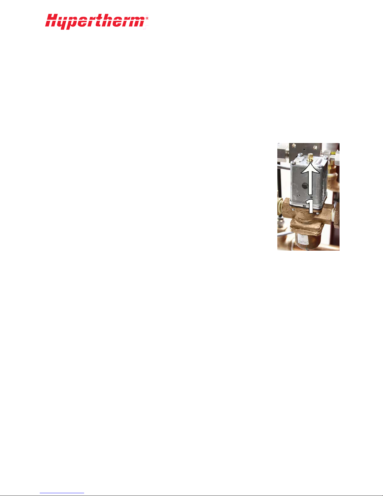
Page 36
A pressure relief valve is also included in-line with the filter assembly
(see picture) to avoid inlet pressures abov e 125 psi. The pressure relief
valve is factory set to 120 psi and should not need adjustment. If either
panel gauges reads over 125 psi, contact an Hypertherm service
representative regarding resetting and/or servicing the pressure relief
valve.
The boost pump is protected from overheating by the PLC control. When there is no demand for cutting
water the boost pump will automatically shut off and not turn on until demand has returned. If the water
pressure falls below the pressure set point of the low-pressure switch the boost pump will resume
operation.
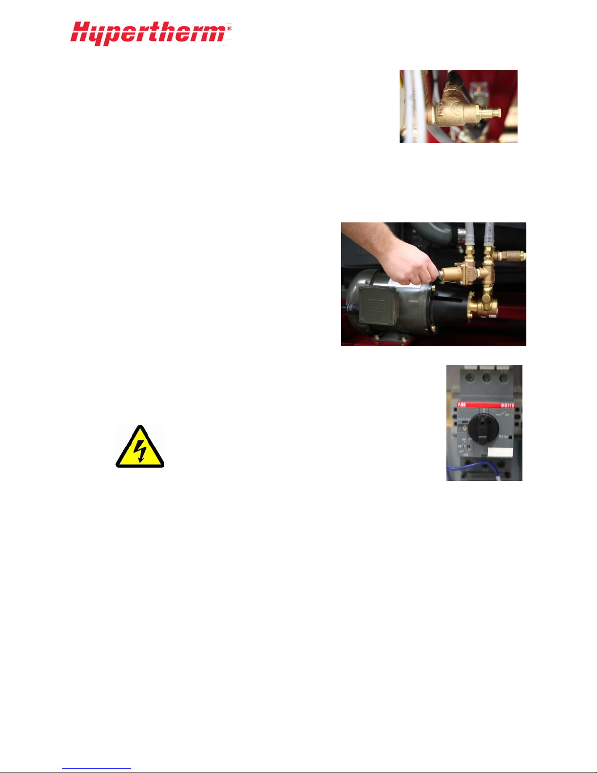
Boost Pump Pressure Adjustment
This adjustment must be made with the pump turned off.
It is factory set to provide correct inlet cutting water
pressure as supplied by municipal water or well pumps. In
cases where the pump is supplied by a tank, such as on a
reverse osmosis system, it is necessary to increase the
boost pressure. The boost pump pressure-relief valve is
adjusted by loosening the jam nut and turning the T-
handled adjustment screw (image at right). Turn clo ck w ise
to increase the pressure or counterclockwise to decrease
pressure.
High Inlet Water Pressure
Inlet water pressure that exceeds 70 psi requires that the boost pump be turned off.
Open the electrical cabinet and turn the switch located on the boost pump motor
contactor to OFF (0).
The electrical cabinet contains high voltage. Extreme
care should be used when working in this area. If you
are unfamiliar with this area, a qualified electr i ci an
should be used.
After turning off the boost pump inside the cabinet, you must also turn off Boost Fault monitoring in the
PLC. This can be done by entering the configuration screen then pressing View Pump Config and
pressing More. Press the button on the screen to change the setting to OFF.
34
Page 37
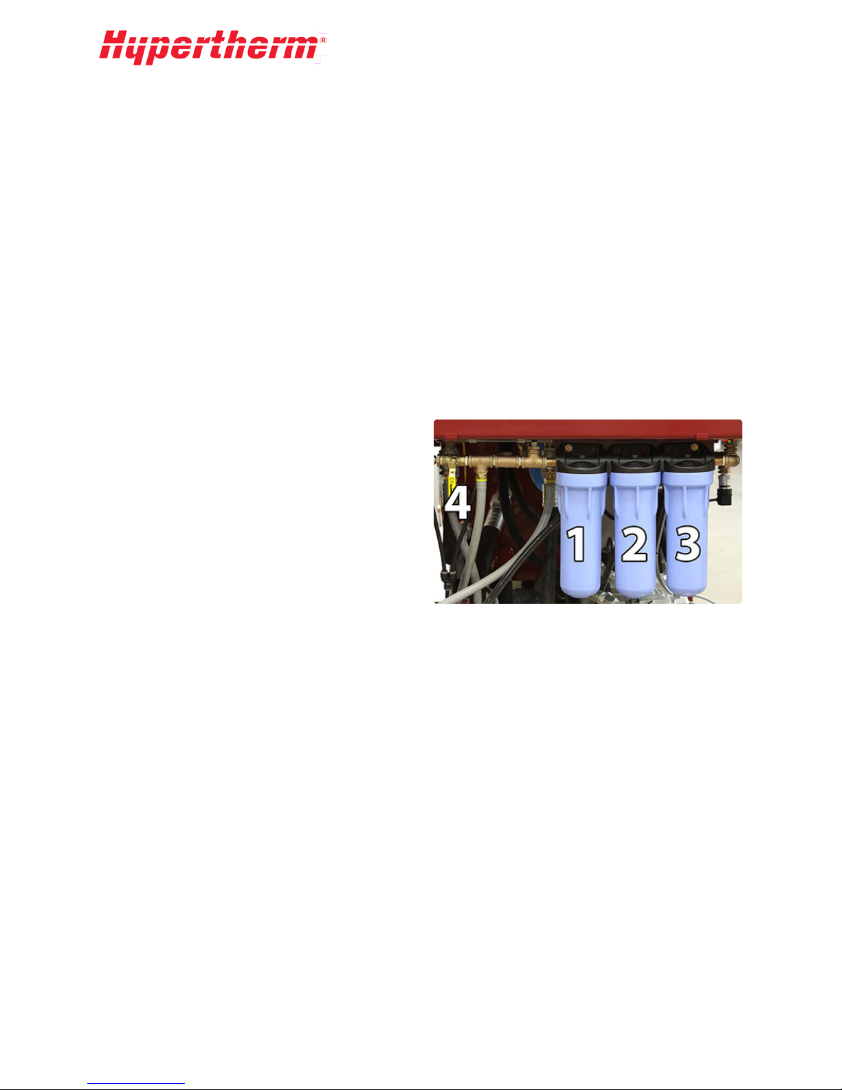
Inlet Cutting Water Filtration
All Hypertherm HyPrecision 100D/150D pumps come with two or th ree water filters that remove
contaminants from the cutting water. Two water gauges are located on the front panel of the pump or on
either side of the filters to show the pressure before and after the filters. These gauges are used to
determine the pressure drop across the filters. Swivel connections are provided at the HP end caps for
easy removal for service. A manual ball valve (4) is provided to discharge the accumulator prior to
performing maintenance. If the filters start to clog to the point that the post-filter water pressure is
below 40 psi and/or the pressure drop across the filters is greater than 15 psi, you must replace
the filters.
In order to maintain necessary water pressure for the pump and to keep the water clean for proper
operation, it is necessary to replace the water filte rs per iodically. The filte rs shou ld be replaced as
needed.
Water Filter Service
Replace filter elements when there is a 10-psi pressure differential between the two gauges located on
the pump control panel.
Replacement Parts:
• 10 Micron Filter (1) (Models with Three Filter
Elements)- AS part # 11107
• 1 Micron Filter (2) (All Models) - AS part
#11106
• 0.45 Micron Filter (3) (All Models) – AS part
# 11105
Recommended Tools:
Strap Wrench or Filter Wrench (for turning filter housing)
Water Filter Element Replacement Procedure
Replacing the filter components
1. Turn the pump off.
2. Open the discharge ball valve (4) to relieve trapped pressure.
3. Unscrew the filter housing from head. Remove element.
4. Install new elements in the housing. Screw the housing into head.
5. Close the discharge ball valv e (4).
6. Turn the pump motor on to turn on the inlet valve and boost pump.
7. Press the bleed valve located on the top of the filter housing to remove trapped air.
8. Start the waterjet pump. Verify satisfactory pressure readings.
Low-Pressure Water Switch (Not all Models)
A pressure switch located after the filters sens es low water pressu re to the int ens ifi er. A sustained
pressure of below 40 psi will result in pump shutdown. This protects the system from running without
enough feed pressure to the intensifiers.
35
Page 38
6.3 Cooling Water Loop (Not all Models)
The cooling loop consists of an inlet water valve to turn on the cooling water. The electronic solenoid
valve (if applicable) will automatically turn on the cooling water any time the motor is running. Models
without an electronic solenoid valve will have to be controlled manually using a ball valve. Models with
water/oil coolers may also have a water-modulating valve to control the cooling water flow rate relative
to the hydraulic oil temperature. A probe in the tank senses the oil temperature and adjusts the water
flow to maintain a steady hydraulic oil temperature.
The modulating valve has been factory set to keep the oil temperature at approximately 115°F (45°C)
Local air and water temperatures may require that the modulating valve be adjusted.
Water Modu lating Valve Adjustment
The oil temperature in the hydraulic tank should be maintained at approximately
115°F. High hydraulic oil temperatures can adversely affect oil life and highpressure seal life.
Adjustment Procedure:
1. If the oil temperature is over 115°F:
2. Turn the screw 1/4 turn clockwise to reduce oil temperature.
3. Wait 15 minutes and look at oil temperature.
4. Repeat procedure until oil temperature is at or below 115°F.
36
Page 39

7 High-Pressure Water
Stay clear of weep holes when unscrewing HP fittings in case pressurized water is
7.1 High-Pressure Water Overview
The high-pressure (HP) water system increases the relatively low-pressure water inlet up to 60,000 psi
(4,137 bar). Maximum flow rates and orifice diameters are provided in the Specifications section of this
manual.
The High-Pressure Assembly consists of the following four (4) major components:
Intensifier
The Intensifier assembly contains three major subsections or cylinders. The center section con ta ins the
hydraulic cylinder and the two (2) outer sections contain the high-pressure ends. The Intensifier
Assembly uses the pumps hydraulic power to reciprocate the center hydraulic piston with a plunger
connected to each side of the piston. The two plungers reciprocate in the high-pressure cylinders to
make the high-pressure water. Each side of the intensifier has one low pressure and one high-pressure
check valve to bring in the inlet water and output high-pressure water.
Bleed-Down Valve
The Bleed-Down Valve Assembly discharges high-pressure water from the pump when the pump is
turned off or when the hydraulic pressure is reduced.
Attenuator
The Attenuator Assembly acts as the accumulator and uses the compressibility of the water to dampen
the output water pressure pulsation caused by the reciprocation of the intensifier.
HP Filter (Optional)
The HP Filter Assembly (optional) is normally located at the pump output or at the upstream end of the
whip for the cutting head.
Instructions are provided that detail the disassembly and reassembly of the hydraulic intensifier and HP
seal maintenance. A detailed description of the inspection and repair for individual HP subassemblies
are provided. HP attenuators are described but no disassembly procedures are included since the
attenuators are not serviceable by the customer.
High-pressure water may be stored in the HP plumbing. Water pressure must be
discharged through the bleed-down valve before starting any service or
maintenance.
discharged.
WARNING
Turn off electrical power and relieve all water and hydraulic pressure prior to
service. Proper lockout/tag-out procedures must always be followed prior to
performing any maintenance.
37
Page 40
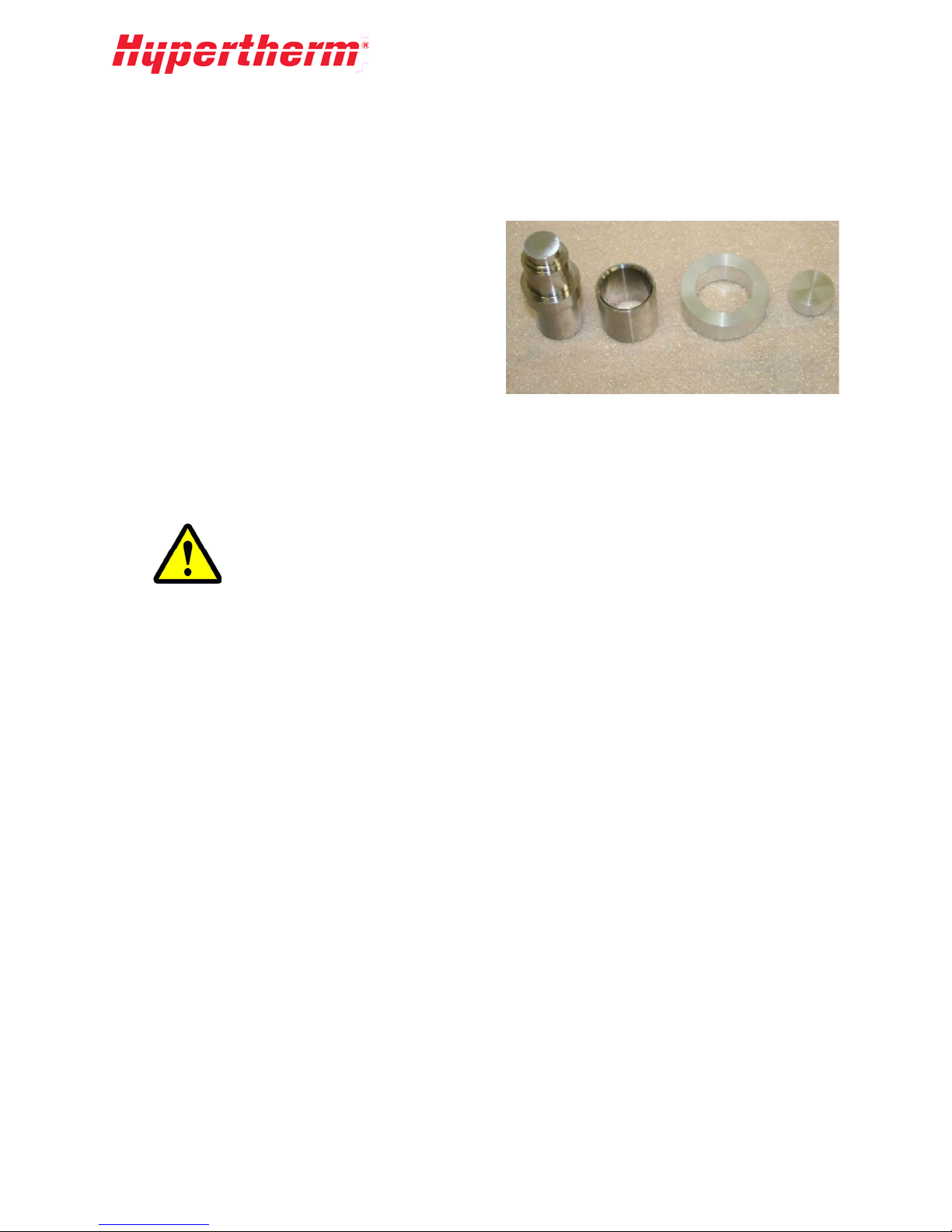
7.2 Intensifier
Special Tools
In addition to any standard tools, the following special tools are required:
• 11557 Seal Insertion Tool Assembly (Includes:
11812 Push Tool, 11811 Sleeve Guide, 11550
Locating Ring, 12932 Spacer Tool)
• 11985 Seal Housing Removal Tool
• 300 ft-lb torque wrench with 3/4 in. square drive
• 1-1/2 Hex x 3/4 in. Square Drive Socket
• 3/4 in. Hex x 3/4 in. Deep Square Drive Socket
• 3/4 x 13-1/2 in. Hex Driver
• High Pressure Food Grade (H1) Lubricant
Due to the high forces inside the intensifier all bolts and cap screws that fasten the load carrying
components are Grade 8. Fasteners that are exposed to cyclic loading use lock washer s. Torque the load
carrying fasteners to the correct Torque Specifications unless otherwise noted.
Keep all interior parts and surfaces clean. All parts should be placed on clean
work surfaces. When changing HP components such as HP seals, hands should
be washed and kept clean. Before reassembling any high pressure or hydraulic
components, verify that the components have been wiped clean to remove any
dirt or other contaminants.
7.3 High-Pressure Ends
High-Pressure Seal Replacement
Replacing the high-pressure seals and hoops is the most common service function. Water dripping from
either end of the HP cylinder indicates that the seals may soon require changing. One drip every few
strokes means that the seals should be watched. More than one drip with each stroke means that the
seals in that HP cylinder should be changed at the first opportunity.
This section will provide the basic information needed do in-house replacements and service on the
high-pressure ends for the HyPrecision 100D/150D pumps. For any questions and all other service
needs please contact 0.15"service rep resen tat iv e.
The high-pressure end drawing shows the locations of the components and their part numbers. Always
check the part lis t inc lu de d w ith th is manual for the latest parts and their replacement part numbers.
38
Page 41

Removing Old HP Seals
1. Remove the high-pressure tubing and inlet water quick-disconnects from
the appropriate end of the intensifier.
2. Remove the four 1 in. nuts from the studs by using a cross pattern t
g
radually unload the high-pressure end cap from the high-pressure
cylinder.
3. Remove the HP end cap and the check valve body from the HP cylinder.
4. Remove the HP cylinder (1) from the plunger (2) and the LP poppet (7)
from the static end of the HP cylinder.
o
The dynamic end of the cylinder is the end towards the intensifier center and the
static cylinder end is the outboard side and contains the LP poppet.
5. Place the stepped (static) end of the cylinder on the seal-tool locating ring. Use a rubber mallet at
the small end of the push tool to drive the bottom seal and hoop out of the HP cylinder. F lip the
cylinder over and repeat the process. The seals (4) with O-rings (6), hoops (5), spacer tube (3),
and low-pressure poppet basket (8) should now be free of the HP cylinder.
6. Remove the bronze seal backup (9) from the seal housing in the hydraulic end cap. It may require
partially removing the seal housing. See the Hydrauli c Seal Ho u s ing subsection of the High-
Pressure Water section for housing removal instructions.
7. Clean and inspect all disassembled parts. If the bronze seal backup (9) is to be reused, verify that
the weep hole and ID groove are clear.
*See the High-Pressure Cylinder subsection for reconditioning of the HP cylinder and check valves.
39
Page 42

Installing New HP Seals
Parts Needed:
• Seal rep lacement tools.
• Seal kit: 4 HP seals with O-rings, 4 hoops, 1grease packet, bronze seal backup.
1. Place the HP cylinder on the spacer tool, then insert the spacer tube, basket, and
LP poppet
2. Place the locating ring and seal guide on the end of the cylinder. The large ID
end of the seal guide should be up. Coat the inner diameter of the seal guide
with the packet grease.
3. Apply grease from the packet onto each O-ring. Place each O-ring onto the
HP seal while making sure that the O-ring does not twist.
4. Place the seal with O-ring inside the seal guide with the O-ring toward the
cylinder.
5. Push the seal into the bore using the non-stepped end of the seal insertion
tool. Always hold the seal guide firmly against the HP cylinder to prevent
the O-ring from cutting as it enters the bore.
6. Place the silver hoop in the seal guide with the sharp edge toward th
c
ylinder.
7. Use the non-stepped end of the seal insertion tool and a soft blow hammer
to pound the hoop into place. The hoop is seated properly when the seal
insertion tool bottoms out on the seal guide.
8. Apply a small amount of grease from the packet around the OD of the pilot
on the check valve body.
9. Carefully insert the check valve body into the end of the high-pressure
cylinder until it is seated firmly against the cylinder body. Do not apply
any grease or blue goop to the check valve face or the cylinder bore, these
are designed for dry contact.
10. Flip the cylinder, place it securely on the check valve body, and repeat
steps 3-5. Apply a very light coat of blue goop to the cylinder contact
face.
e
Use a clean rag to wipe the interior of the LP basket so that
there is no grease to make the LP poppet stick.
IMPORTANT
The bronze backup seal can be reused only once. Install
either a new backup or reuse (flip) the old one. It may be
necessary to pull the seal housing out slightly to access
and remove the backup. (See the Hydraulic Seal Housing
section.)
40
Page 43

Reinstalling the High-Pressure Ends
1. Push the HP cylinder onto the plunger.
2. Place the HP end cap over the studs and make sure it
guides smoothly onto the check valve body making
sure to not unseat the O-rings on the check valve
body.
3. Grease the stud threads with multi-purpose lithium
grease such as Lubriplate No. 1552.
4. Using two 1 in. nuts located diagonally lightly torque
the HP end cap so that it is bottomed onto the HP
cylinder.
5. Torque the 1 in. nuts to 125 ft-lb. Then, using a cross pattern, increase torque in 50 ft-l
i
ncrements to 275 ft-lb.
6. Reattach the high pressure and low-pressure plumbing.
7. Turn the inlet water ON and open a cutting head. Allow the pump to cycle slowly at low pressur
f
or a few minutes to ensure that the seals seat properly before returning to operating pressure.
b
High-Pressure Cylinder
During normal use the inner surfaces at the ends of the HP
cylinder may become worn. To clean this area roll polish the
ID (Inside Diameter) of the cylinder ends on a table. First use
180 grit or finer abrasive paper, then finish with a ScotchBrite pad.
HP cylinders may eventually fail due to fatigue leading to a crack or the ends may open or bell out so
that the cylinder does not hold the seal and hoop properly. If the cylinder is cracked it will be hot and
water may squirt with each stroke. This fa ilure may appear to be a seal failure. A belled out cylinder end
will cause the premature failure of the seal and cause the hoop to break.
e
7.4 Check Valve Assembly
Check valve replacement and reconditioning is the second
most common intensifier maintenance. The low-pressure
check valve allows inlet water to enter the HP cylinder and
the HP poppet lets the pressurized water from the HP
cylinder exit the in ten s if ie r. Over time the faces of the
poppet, seat, and check valve body may become worn.
The check valve repair process involves replacing the H P
poppet (5), HP seat (7), poppet spring (6), and LP poppet (4),
as well as lapping the face of the check valve body.
Check valve repair may be necessary when the HP end cap area becomes hot to
the touch or the intensifier strokes faster in one direction without seal leakage.
41
Page 44

Weep Hole Le akage (See previous figure)
• Weep Hole #1 (10) leakage means that the inlet fitting needs to be tightened into the output adapter.
• Weep Hole #2 (11) leakage means that the output adapter needs to be tightened into the check valv
body
.
Check Valve Replacem ent and Recond itioning
Required Parts:
• Poppet kit, which includes: 1 HP poppet, 1 HP seat, 1 poppet spring, 1 LP poppet, 3 O-rings
• High-pressure lubricant.
1. Remove the HP end cap (1) from the HP cylinder as described in the section on Removing Old
HP Seals.
2. Unscrew the output adapter (3) from the check valve body, remove, and discard the HP poppet
(5), poppet spring (6) and the HP seat (7).
3. Inspect the low-pressure poppet face of the check valve body (2). A worn face on the poppet (4)
or check valve indicates that it should be lapped as described in the next section.
4. Apply HP lubricant to both sides of the HP seat (7) and place the seat in the cavity of the check
valve body (2).
5. Install the poppet spring (6) and HP poppet (5) into the output adapter (3) and tighten the adapter
into the check valve body (2).
6. Replace the O-rings (8) (9) on the outside of the check valve body (2).
7. Verify that the basket interior is free of grease.
8. Replace the LP poppet (4) in the poppet basket located in the static end of the HP cylinder. Do
put any lubricant here. The lubricant may prevent the LP poppet from moving freely.
not
9. Reassemble the end of the intensifier as described above in Installing New HP Seals.
e
42
Page 45

Check Valve Lapping Instructions
During use, the check valve body face (1) becomes worn from the
action of the LP poppet. It may be indented from repeated poppet
impact or have erosion tracks. This deformation will affect the
sealing properties of this part. Periodically inspect this surface and
if necessary use the lapping procedure to return it to a flat and
near mirror finish. Proper lapping will help maintain the sealing
properties and increase the life of the part.
Repeated lapping may shorten the check valve dimensions and render it
unusable. If the sealing face is less than 0.385 in. from the body diameter area
(dimension X), it should be replaced.
This procedure is for a moderately worn check valve body face. Severe wear requires turning on a lathe
or grinding on a precision surface grinder prior to lapping.
If the sealing face (1) has slight indentations only, use 1500 grit paper. Lapping is complete when the
check valve body face is flat and has a near mirror finish.
Deeper indentations will need to be lapped with 600 grit SiC abrasive paper first. Lapping is complete
with this abrasive paper when the face has an even appearance and any indentations are removed.
The following items are required for the lapping procedure:
• Gra ni te in spection plate at least 9 in. x 12 in.
• 8.5 in. x 11 in. sheets of 600 and 1500 grit SiC abrasive paper
• Lapping film
Lapping Procedure:
1. Place either the abrasive paper or lapping film on
t
he granite plate and secure the film in place with
masking tape around the edges.
2. Hold the check valve flat against the abrasiv
surface to prevent any rocking of the part. Move
the check valve body (2) back and forth on the film
or paper. Rotate the valve 45 degrees after each
movement until the face of the body (1) is evenly
finished. Repeat this procedure for the poppet
face if needed.
e
43
Page 46

7.5 Hydraulic Seal Housing
Removing the hydraulic seal housing provides access to the rod seal. If oil is observed in the seal area
during HP seal replacement, the rod seal should be replaced.
1. With the HP cylinder removed, slide the seal housing removal tool over the
xposed seal-housing diameter and into the groove.
e
2. Use an Allen wrench to turn the two screws on the tool. Start with one tur
o each screw to pull the seal housing evenly out of the hydraulic end cap.
t
3. Inspect the condition of the HP seal backup and flip or replace as
n
ecessary. Check for any inner diameter corner chipping or a loose fit on
the plunger.
4. Remove the old seal from the seal housing.
5. Replace the O-ring and backup ring on the OD of the seal housing
osition the O-ring on the rod seal side of the groove and backup on the
P
backup side of the groove. Note the position of the groove on the backup
ring.
.
n
6. Apply HP lubricant to the outside of the O-ring and to the ID of
the rod seal.
7. Apply a light coat of hydraulic fluid to the ceramic plunger a
s
lide the Rod Seal over the end of the plunger. Note the
orientation of the rod seal during installation.
8. Push and rotate the seal housing and rod seal over the plunger
end until it is up against the end cap as far as it will go.
nd
44
Page 47

7.6 Hydraulic Center Section
The hydraulic center section houses the piston and the plungers. This section describes the service of
this area with the HP cylinders removed and the center section removed from the pump.
Hydraulic Ce nter Section Disassembly
1. Unscrew the eight bolts in the back of the manifold that connect it to the end caps.
2. With the HP cylinders removed, loosen but do not remove the four 7/8 in. cap screws that preloa
he two hydraulic end caps together. Use a 3/4 in. hex x 3/4 in. deep square drive socket and a
t
3/4 in. hex x 13-1/2 in. hex driver.
3. Unscrew and remove the four bolts under the hydraulic end caps that secure the intensifier
assembly to the frame.
4. Place the center section on a clean workbench and remove the four 7/8 in. cap screws. Cover the
manifold oil ports to prevent contamination.
5. Pull the end caps off the hydraulic cylinder. (This will take two people).
d
Hydraulic Center Plunger Replacement
After extended use, the plunger surface may become damaged and/or scored.
1. Push the hydraulic piston to the end of the hydraulic cylinder so that the plunger is accessible.
Use a rubber mallet to drive the opposite plunger end. Do not remove the piston from the
cylinder. Special tooling is required to reload the piston into the cylinder.
2. Use locking snap-ring pliers on the retaining ring and remove the plunger retainer and plunger.
3. Replace the t-seal and its backups. The ID of the backup seal has a corner radius and should be
towards the t-seal. The angle-cut ends of the backup must overlap properly.
4. Squirt a small amount of hydraulic fluid in the bottom of the piston cavity and lubricate the t-seal.
5. Push the new plunger into the t-seal, replace the plunger retainer, and reinstall the retaining ring.
45
Page 48

Piston Seal and Wear Ring Replacement
The piston uses a long life, capped t-seal and wear rings for the longest possible life. After extended use,
the intensifier may not stroke efficiently and the pump will generate heat. This is a sign that the piston
seal is bypassing oil and needs to be replaced. Special tools are required to load th e new seal on the
piston and load the new piston/seal assembly into the hydraulic cylinder. Contact an authorized
Hypertherm service representative for further information regarding this procedure.
Plunger Be aring
The plunger bearing may become worn and may lose its precision fit relative to the plunger. The bearing
should be replaced if the plunger fit is too loose. A bearing ID measurement of 0.0015 in. greater than
the plunger diameter is considered too loos e. The bearing can be changed when the hydraulic end cap is
off the hydraulic cylinder. Repeated premature seal failure can be attributed to a worn out bearing. The
bearing should also be replaced any time a high-pressure cylinder is replaced.
Reassembling the Center Section
1. Verify that all surfaces are clean and free of contamination.
2. Replace the O-ring and backup on the end cap. Place the O-ring on the side of the groove towards
the piston and the backup on the side away from the piston. The concave side of the backup is
towards the O-ring. Lubricate the O-ring with hydraulic oil.
3. Install the plunger bearings in the end caps.
4. On a flat clean surface, slide the hydraulic end caps into each end of the hydraulic cylinder.
5. Thread the four 7/8 in. cap screws in and lightly pull the end caps against the hydraulic cylinder
until they bottom-out. The cap screw threads should be greased with multi-purpose lithium
grease such as Lubriplate No. 1552.
6. Secure the center section and manifold mounting face to a flat surface before applying torque t
t
he 7/8 in. cap screws. Bolt it to the manifold first and then to the frame on the pump before
applying torque.
7. Torque the 7/8 in. cap screws to 100 ft-lb. Then increase torque in 50 ft-lb increments using a
cross pattern to 275 ft-lb.
o
The eight bolts that connect the manifold to the hydraulic end caps must be
torqued to the appropriate value as given in the Torque Specifications section of
this manual.
8. Reassemble the end of the intensifier as des cribed above in Installing New HP Seals.
9. When reconnecting the HP tubing loosen the four bolts that secure the intensifier to the frame.
This will allow it to float into the correct location. Tighten the four frame connect bolts.
46
Page 49
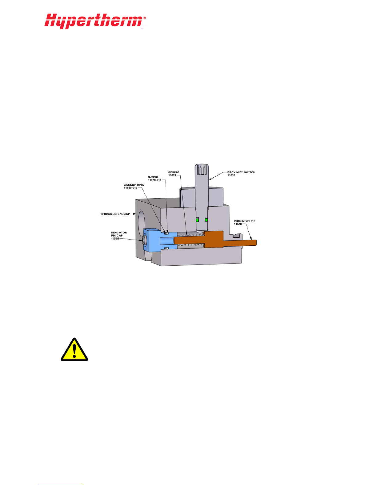
7.7 Intensifier Cycling
Under normal operating conditions, the intensifier is designed to cycle smoothly in both directions at the
same speed.
Leaks or HP component failures will cause the intensifier to overstroke in one or both directions.
Severe overstroking can cause a fault condition and/or a pump shutdown. An arrow on the display
screen will indicate the direction of overstroke. If an overstroke shutdown or harsh cycling occurs, it is
important to observe the pump operation before attempting to fix the problem.
• Turn on the pump and intensifier at a reduced cutting pressure of 1,000-psi hydraulic pressure.
• Gradually increase the pressure until the nature of the problem is present.
• Use the proximity switch lights to determine which direction the intensifier is over cycling while
looking for any leaks.
End of Travel Sensing
When the hydraulic piston reaches the end of travel on either side of the cylinder it will push against an
indicator pin. The proximity switch above the pin will sense the larger diameter of the pin as it passes
under the switch. This pin should move freely in and out to the bottom of its travel. To gain access to
the indicator pin remove the indicator cap from the end cap.
Use the specified torque when reassembling the indicator pin cap and proximity
switch.
Intensifie r Overstroking Equally in Both Directions
Overstroking equally in both directions is most likely caused by a leak. Check the tubing and fittings
inside and outside the pump and fix any leaks. Check the bleed-down valve. If the valve feels hot or if
water is coming out the pump drain line then the bleed-down valve should be rebuilt with a new kit.
A blown orifice at the cutting head will also increase the HP water requirements.
The intensifier water inlet could be starved without setting off the low-pressure alarm. Check the quick
disconnects to the intensifier to be sure all fittings are tight and no water is leaking.
47
Page 50

Intensifie r Overstroking in One Direction
This indicates a problem inside the intensifier, specifically the LP poppet or HP check valve area. Verify
that the inlet water is connected to th e in t ensifier. Look for leaking from either end of the HP cylinder.
Replace HP seals if necessary. If the HP cylinder or check valve body is hot, disassemble and look for
cracks. Any component that is cracked must be replaced.
If there are no visible leaks from any weep holes then one of the poppet and seat areas may be bypassing
water. Inspect both of the HP poppets and seats and both LP poppets. Inspect the check valve body-face.
Replace and/or recondition the damaged poppet faces.
7.8 Pump Bleed-Down Valve
The pump bleed-down valve discharges high-pressure water from the pump when the pump is turned
off. It operates as a normally-open safety valve and is controlled by an air-actuated valve. The bleeddown valve is located inside behind the utility panel at the front of the pump.
Bleed-Down Valve Repair
The Bleed-Down Valve repair kit 12981 contains one each of
the following:
• Seal Hoop 11323
• Needle(Stem) 12942
• Seal, FL 11321
• Bushing 11324
• Poppet Seat 11141
Kit installation procedure:
1. Shut down the system.
2. Remove the hydraulic hose from the bleed-down valve and gland nut connection from the water
drain tubing to the bleed-down valve.
3. Remove the gland nut from the collar at the high-pressure port of the bleed-down valve.
4. Disconnect the actuator from the high-pressure valv
assembly. Remove all the hydraulic fittings from
the actuator housing.
5. Remove the adapter from the bleed-down valve
body. Remove and discard the HP seat.
6. Remove all the internal com ponents from the bleeddown valve body.
7. Push the piston out of the actuator housing body
through the oil port. Discard the o-ring and backup
ring from the piston.
8. Clean all parts before the new parts are installed.
9. Lubricate the new o-ring and backup ring with grease from the supplied packet and install the
rings in the same order as the old O-ring s (previous figure). Install the piston assembly carefully
into the actuator body until it is seated securely and no damage has been caused to the o-ring.
10. Secure the hydraulic fitting to the end of the actuator housing.
11. Apply Blue Goop to both sides of the HP seat and to the flow reducer and place them into the
valve body as shown. Tighten the outlet adapter on the end to secure the parts.
e
48
Page 51
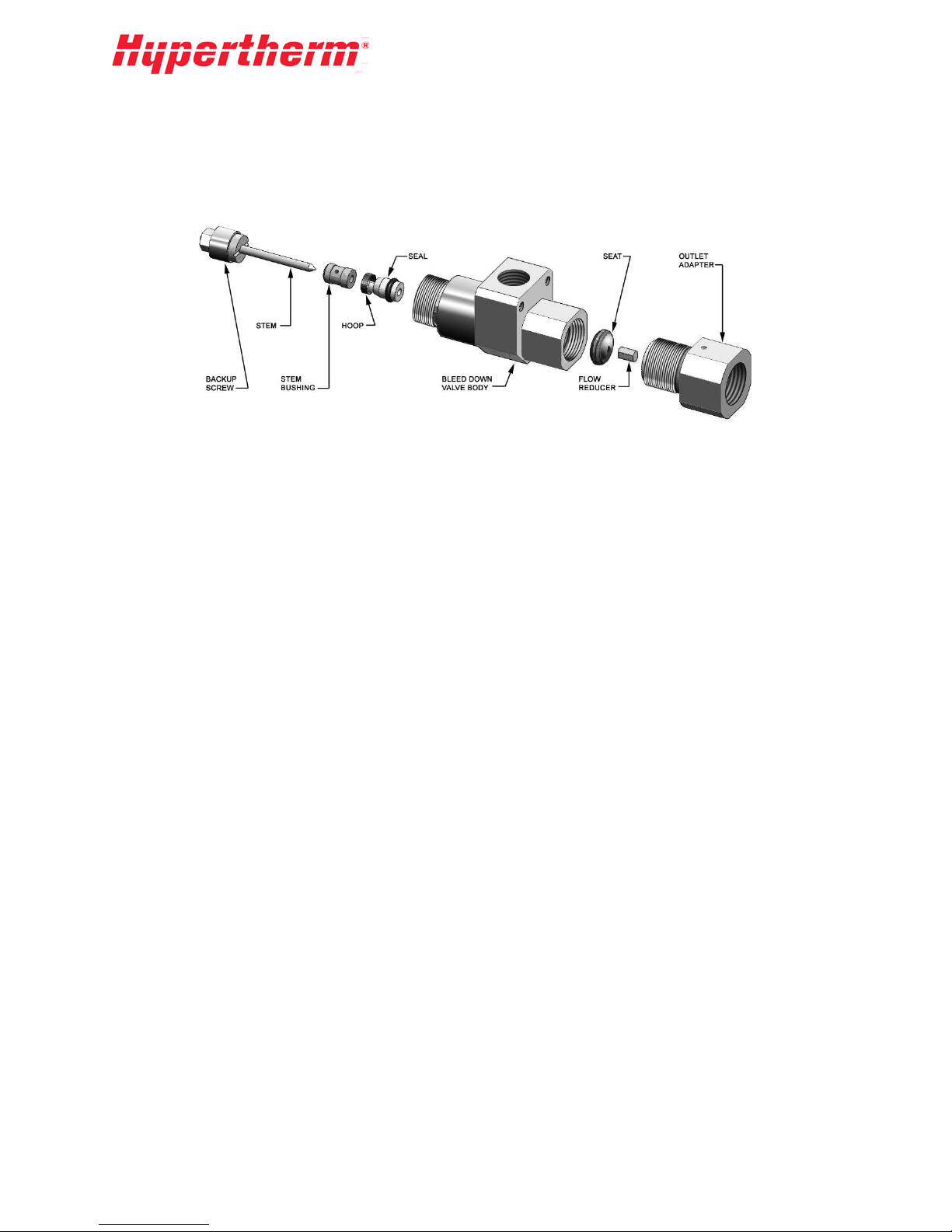
12. Place the stem flat side out, into the backup screw. Place the stem bushing, hoop, and seal on the
stem in the order shown below. The seal should fit into the hoop’s sharp side. Use HP lubricant
to lubricate the OD of the seal and o-ring before they are inserted into the valve body.
13. Push the assembled parts into the valve body and use a 5/16 socket tool to screw the backup
screw securely into the valve body.
14. Apply Blue Goop to the threads of the bleed-down valve body and secure the valve to the
actuator housing.
15. Reinstall the b le ed -down valve in the machine by attaching the gland nut to the high-pressur
llar at the high-pressure port of the valve. Torque the gland nut to 35 ft-lb.
co
16. Install the gland nut connecting the water drain tubing to the bleed-down valve.
17. Reattach the hydraulic hose to the oil port of the bleed-down valve.
The intensifier is now ready for use. Turn pump on and check for any leakage.
e
7.9 Attenuator
Hypertherm pumps are equipped with an attenuator with a volume of either 1 liter or 2 liters depending
on the size pump.
The 1-liter attenuator uses 3/8 in. HP fittings. The 2-liter attenuator uses 9/16 in. male x 3/8 in. female
inlet adapters on either end to connect to the 3/8 in. HP plumbing. Leakage from the inlet adapter or
fitting weep holes can be addressed by tightening the adapters and fittings into the attenuator end caps.
Leakage from the end cap weep-hole or the gap between the end cap and the attenuator body is not
serviceable by the user. If leakage persists from this area, contact a Hypertherm service representative
for further assistance.
7.10 High-Pressure Filter Assembly (Optional)
The HP filter assembly is an optional product available to screen small particles of debris out of the
high-pressure lines from the pump. The high-pressure filter is locate d at th e outpu t of the pump. It
contains a screen filter element that should be replaced on a regular basis. See the Scheduled
Maintenance Chart for a replacement timing guideline. The quality of water may increase or decrease
the duration between filter element replacements. Alway s replace the fil ter at the recom mended interval.
Failure to replace the filter can result in the screen breaking which will release all trapped debris
downstream into the high-pressure lines. This can cause orifice and valve damage.
49
Page 52

7.11 High-Pressure Plumbing Weep Holes
Weep holes throughout the HP water system relieve the water seepage from any leaking components
(for example, see Check Valve Assembly). Seepage from any of the holes indicates a faulty
component, loose connection, or damaged seat. Failure to correct the cause may result in damage to the
mating fittings.
If weep hole leakage is observed, the fitting may have loosened and it will need to be tightened. Another
cause of seepage is the collar on the tubing may need to be threaded further onto the tubing. Persistent
seepage may require replacing the fitting or tube.
Lubricate the high-pressure fittings with a HP grease such as Blue Goop. To minimize side load, use
two wrenches to tighten the high-pressure fittings: one on the gland and the other on the fitting.
50
Page 53
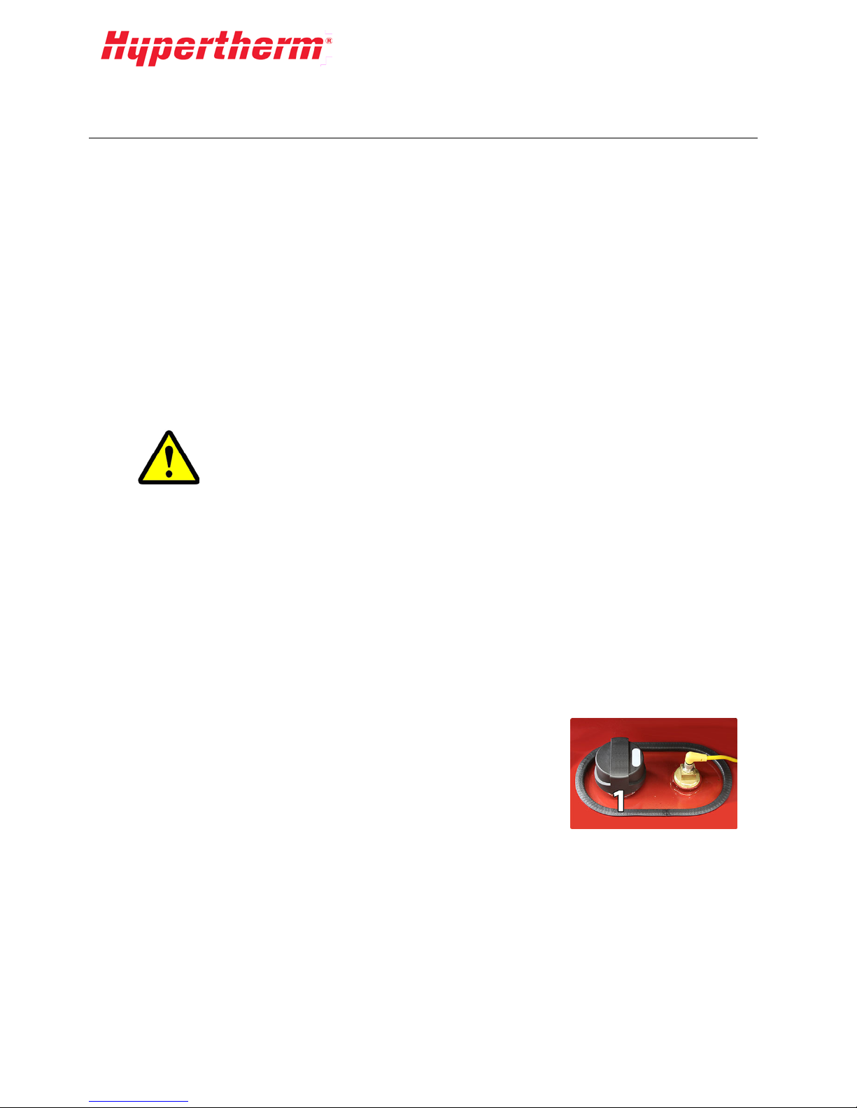
8 Hydraulic
Hydraulic Overview
Hydraulic pressure and flow from a pressure compensated variable displacement (PCVD) piston pump
is passed through a spool valve where it is directed to either side of the hydraulic piston in the intensifier
center section. The intensif i er will recip roca te and crea t e high-pressure water as output.
The pump compensator and the control manifold assembly control the hydraulic pump pressure. The
manifold assembly is connected to the pressure compensator port on the pump. The control manifold
has a pressure control valve for adjusting pierce pressure; the cut pressure is adjusted using the pump
compensator. When the pump is turned off, a solenoid valve in the manifold opens and the hydraulic
pressure goes to its minimum. Some pumps may have additional hydraulic components for electronic
control of the pump pressure. Refer to the Drawings and Parts Lists section of the manual for detailed
information on your pumps hydraulic circuit.
The larger pumps filter and clean oil using a "Kidney Loop". In systems with a kidney loop, the oil is
drawn from the hydraulic tank through the gear pump mounted on the end of the PCVD pump. The oil
then passes through the filter and heat exchanger before returning to the hydraulic tank .
Before starting any ser vice or maintenance, turn off electrical power and relieve
all water and hydraulic pressure. Proper lockout/tag-out procedures must always
be followed prior to performing any maintenance of the unit.
WARNING
8.1 Hydraulic Oil
Hydraulic Oil Requirements
Please reference chapter 9 for specific pump requirements.
Adding New Hydraulic O il
Hypertherm intensifier pumps require Castrol Hyspin 32 or Hyspin 46 Hydraulic oil.
To add new oil, follow this procedure:
1. V
erify that the ball valve on the bottom of the hydraulic tank is closed.
2. Unscrew the filler/breather cov er (1) on top of the hydraulic tank.
3. Fill with the appropriate oil until the o il lev e l is visible at the top
of the sight gauge at the front of the hydraulic tank. Do not
overfill tank !
4. Replace the filler/breather cover (1).
Evaluating Old Hydraulic Oil
Oil quality can be estimated by the appearance or smell. New oil is almost clear and has no odor. When
the oil color is like dark honey and it has a poor odor, it is time to replace the oil. A supplier can
measure the oil quality more precisely. Water and/or high temperatures can damage the oil. Any time
the oil is replaced, the hydraulic filter should also be replaced.
51
Page 54

High Temperature
Running the pump at a high oil temperature will shorten the oil life. Excessive oil temperatures will
darken the oils color and its smell will worsen. The recommended oil temperatu re is under 130ºF but not
less than 100ºF. The pump system will give a high temperature warning at 130ºF and shutdown at
150ºF. See the Low-Pressure Water section for instructions on adjusting the water-modulating valve
for water/oil cooled units. Air/oil cooled units should not need any adjustment. If you are having chronic
overheating conditions with an air/oil cooler contact a Hypertherm service representative for further
instruction.
Water Contamination
A milky oil appearance will indicate that there is water in the oil, or “water contamination”. If the
hydraulic oil has been contaminated it can damage the hydraulic pump. The pump will need to be shut
down immediately and the oil will have to be drained. Once the oil is drained, all the components must
be cleaned. Water can be in jected into the oil from the dynamic water seal in the intensifier. A badly
leaking dynamic water seal can squirt water past the rod seal into the oil (see the High-Pressure Water
section).
The oil, dynamic seal, and rod seal will need to be replaced. If you have water in your oil please report
the incident to an authorized Hypertherm service representative to receive any additional instructions.
Oil Replacement Procedure
While changing the oil, consider thoroughly cleaning out the hydraulic system.
Requires:
• Appropriately sized suction strainers
• Appropriately sized return diffusers (if applicable)
• Hydraulic Filter Element
• New oil, provided by your supplier
1. Drain the oil from the hydraulic tank using the ball valve at the bottom of the tank.
2. Remove the access cover of the hydraulic tank.
3. Remove and discard the suction strainers in the tank.
4. Thoroughly clean the tank interior. Make sure no particulates remain on the bottom.
5. Install new suction strainers. DO NOT use Teflon tape or pipe dope.
6. Drain the oil in the hydraulic hoses by disconnecting one end.
7. Reinstall hoses.
8. Replace the oil filter element. (See the Oil Filter section that follows).
9. Close the ball valve drain and rein s ta ll th e tan k access cover.
10. Fill the hydraulic tank with new oil.
11. Let the oil sit until any bubbles dissipate.
12. Start the pump at low pressure and check for hose leaks.
52
Page 55

In the case of severe contamination such as with water, drain and clean out other
areas such as the shift valve, main manifold, and the hydraulic pump.
8.2 Control Manifold
The control manifold consists of two solenoid valves for high (5) or low (4) pressure selection, two
pressure control knobs for setting of the high and low pressures, a small accumulator (1), and a gauge
for the hydraulic pressure. The control manifold connects to the pump compensator port and has a
connection to the hydraulic tank. Some HyPrecision pumps may be available with electronic pressure
compensation. The following control manifold sections refer to pumps that do not have this option. For
systems equipped with electronic pressure compensation contact Hypertherm for information on
adjusting the pressure.
Cutting Pressure Knob and Pierce Pressure Knob
The cutting pressure and pierce pressure knobs are located
on the front of the control manifold and are used to adjust the
cutting and pierce pressures. See the Operation section for
instructions on setting the operating pressure.
Cut Pressure Select Solenoid Valve
The cut pressure select solenoid valve (5) is a normally open
valve located on the back of the control manifold directly
behind the cutting pressure knob. In the event of a power
loss, the solenoid will discharge pressure from the hydraulic
system and cause the bleed-down valve (2) to relieve highpressure water. This solenoid has a manual override (3). If
solenoid coil fails, the valve can be manually turned on until
the coil is replaced.
Using the cut pressure select manual override will prevent the discharge of
hydraulic and water pressure at shutdown. Pump pressure ramp-up wil l be abrupt.
This feature should only be used as a temporary feature until a new solenoid coil
is installed.
WARNING
Hydraulic Gauge
The hydraulic gauge shows the operating pressure of the system. It is also used to determine the current
cutting water pressure. Multiply the gauge value by the intensification ratio of 19.25:1 to get the current
water pressure. A gauge pressure of 3,000 psi will have the output pressure of about 57,000 psi.
53
Page 56
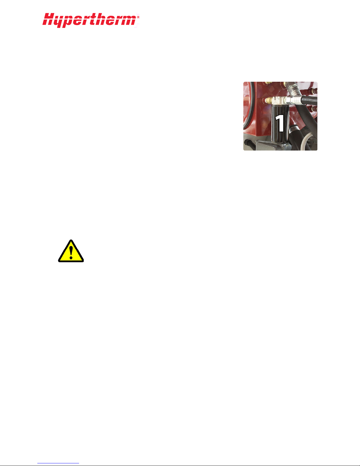
8.3 Oil Filter
The oil filter is installed in line with the heat exchanger. The filter element should be changed when the
oil is changed or at the maintenance interval given in the Maintenance and Troubleshooting section.
Filter element replacement procedure:
Requires 1 - Filter Element
1. Unscrew the filter (1) from the top housing.
2. Discard the old filter element.
3. Install the new element according to the diagram that comes with
the element.
8.4 Heat Exchanger
HyPrecision 100D/150D pumps are equipped with a water/oil heat exchanger and a gear pump.
The gear pump is located on the end of the main motor and is part of the “Kidney Loop” system used
for cooling the hydraulic oil. The type of cooling system will vary according to system size and
customer preferences.
Water/Oil E xchanger (Standard)
If your pump is equipped with the water/oil heat exchanger, the gear pum p will de liver the oil to the
hydraulic filter before going through the heat exchanger and back to the pump. The heat exchanger is
sized for use with water.
If you are using a chiller with water/glycol solution the efficiency of the heat
exchanger will be reduced and may require reducing the temperature set point of
a chiller.
The oil temperature variations coming from the heat exchanger can be controlled by adjusting the flow
rate of water. The flow rate of the water can be adjusted by either the water-modulating valve (if
applicable) or a manual ball valve.
For directions on adjusting the water-modulating valve please refer to the Low-Pressure Water section
of this manual.
For best long-term performance, the cooling water should be low in total dissolved solids (TDS). High
TDS levels can lead to clogging and loss of efficiency in the heat exchanger.
Air/Oil Exchanger (Optional)
If your pump is equipped with an air/oil cooler, the gear pump will deliver the oil through a one-inch
external hydraulic hose to the air/oil cooler and back to the bulkhead on the pump. The cooler uses a
radiator with an external fan powered by a fractional horsepower motor to cool the oil temperature to an
acceptable range.
The air/oil cooler fan will automatically turn on once the hydraulic oil reaches the factory set
temperature. Once running, the fan will remain on for a minimum of 10 minutes. If after 10 minutes, the
oil is still above the preset temperature the fan will remain on until the oil has dropped below that
temperature.
54
Page 57

8.5 Hydraulic Tank
The hydraulic tank has the following features:
• Sight gauge and thermometer for seeing the oil level and its temperature
• Filler/breather cap to keep the contents of the tank free of airborne con tamination
• Level sensor with temperature switches which monitor the tank for low level and high temperatur
a
larm conditions
• Inlet suction strainers to prevent contamination from reaching the main PCVD pump and the gear
pump or kidney loop system.
8.6 Main Pump Setup
Contact Hypertherm if the main hydraulic pump needs to be replaced. Detailed setup information is
available upon request.
e
55
Page 58

56
Page 59

9 Specifications
The following specification s des cribe the requ ir ements and capabilities of the AS-Series pumps.
9.1 Pump Requirements
50hp
(37kW)
Frequency (Hz) 50 60 50 60 50 60 50 60 50 60
Pump Power
Voltage (V)
Current (I)
Main C.B. Rating (I)
Physical
Width
Size
Length
Height
Clearance Height
Shipping Weight
Approx.
(in crate, no oil)
400
70 135/67 105 95 150 120 215 170
90
3200lb
(1450kg)
(45kW)
230/460
60hp
230
175/100
/460
75hp
(56kW)
100hp
(75kW)
150hp
(112kW)
400 460 400 460 400 460
125 125 175 150 250 200
80in (2.03m) 45 (1.15m)
42in (1.07m) 86 (2.18m)
58in (1.47m) 56 (1.42m)
80in (2.03m) 80in (2.03m) 80in (2.03m)
3300lb (1497kg) 3400lb (1540kg) 4250lb (1928kg) 6250lb (2834kg)
Operating Weight
Approx.
Ambient Conditions
Min. Storage Temp.
(not drained)
Min. Operating
Temp.
Max. Operating
Temp.
Max. Relative
Humidity
Inlet Cutting Water
Min. Inlet
Water Pressure
3100lb
(1406kg)
3200lb (1450kg) 3300lb (1497kg)
3300lb (1497kg)
4150lb (1882kg)
35°F (1.7°C)
40°F (4.4°C)
95°F (35°C)
Note: higher temperature operation available with additional cooling package
95%
40 psi (1.38 bar)
6100lb
(2767kg)
57
Page 60

50hp
(37kW)
Frequency (Hz) 50 60 50 60 50 60 50 60 50 60
Max. Inlet
Water Pressure
(See LP Water
section)
60hp
(45kW)
75hp
(56kW)
115 psi (7.72 bar)
100hp
(75kW)
150hp
(112kW)
Max. Inlet Temp.
Min. Inlet Temp.
Min. Inlet
Flow Rate
Inlet Water Quality
Hydraulic Cooling Water (if not air cooled)
Min. Inlet
Water Pressure
Max. Inlet
Water Pressure
(See LP Water
section)
Max. Inlet Temp.
Min. Inlet Temp.
Normal Inlet Flow
Rate
Hydraulics
2 gpm (7.6 lpm) 2.5 gpm (9.5 lpm) 4 gpm (15.1 lpm)
3 gpm
(11.5 lpm)
70°F (21°C)
40°F (4.4°C)
See Water Quality section
40 psi (2.76 bar)
115 (7.93 bar)
70°F (21°C)
40°F (4.4°C)
4 gpm
(15 lpm)
8 gpm
(30 lpm)
5 gpm (18.9 lpm)
10 gpm
(38 lpm)
Hydraulic Oil Type
Hydraulic Oil
Capacity
Max. Oil Temp.
Min. Oil Temp.
Castrol Hyspin 32 or Hyspin 46 Hydraulic Oil
38 gal (144 L) 55 gal (208 L) 96 gal (363 L)
130°F (55°C)
55°F (12.8°C)
58
Page 61

Pump Factory Settings
Hydraulic
Pump
Pressure Limit
3200 psi (220 bar)
Cut Pressure
Set Point
Pierce
Pressure
Set Point
Utility Hook-Ups (located at rear of pump)
Cooling In
Cooling Out
Cutting Water
In
Drain Water
Out
Cutting Water
Out
Warnings and Shutdowns
Intensifier HP
Leak Warning
Intensifier
Over Cycle
Factory Set to Minimum Pressure for Startup.
Adjust per startup operating instructions in this manual.
Factory Set to Minimum Pressure for Startup.
Adjust per startup operating instruction in this manual.
1 NPT Female
1 NPT Female
3/4 NPT Female
3/4 NPT Female
3/8 HP Female 9/16 HP Female
Warning
Shutdown
Inlet Cutting
Water Under
Pressure
Hydraulic Oil
Level Low
Hydraulic Oil
Temp.
Alert Temp
Hydraulic Oil
Temp.
Shutdown
Temp
Motor Fault
P < 40 psi (2.8 bar) Shutdown
Shutdown
T > 131°F (55°C) Warning
T > 150°F (65°C) Shutdown
Shutdown
59
Page 62

TDS METER
9.2 Pump Capabilities
Frequency (Hz)
Max. Continuous
Output Pressure
Min. Output
Pressure
Max. Output Flow
gpm (lpm)
50hp
(37kW)
50 60 50 60 50 60 50 60 50 60
1.0
(3.79)
1.1
(4.16)
(45kW)
1.2
(4.54)
60hp
1.3
(4.92)
75hp
(56kW)
60,000 psi (4137 bar)
8,000 psi (552 bar)
1.5
(5.68)
1.6
(6.05)
(75kW)
2.1
(7.95)
100hp
2.2
(8.33)
150hp
(112kW)
3.0
(11.4)
9.3 Orifice Combinations
This pump will support at least the following orifice sizes (sizes are in inches):
50hp
(37kW)
Frequency (Hz) 50 60 50 60 50 60 50 60 50 60
1 Orifice
2 Orifices
.014 .015 .015 .016 .017 .018 .020 .021 .024 .025
.010 .010 .011 .011 .012 .013 .014 .015 .017 .018
60hp
(45kW)
75hp
(56kW)
100hp
(75kW)
150hp
(112kW)
3.2
(12.1)
3 Orifices
4 Orifices
5 Orifices
6 Orifices
.008 .008 .009 .009 .010 .010 .011 .012 .014 .014
.007 .007 .008 .008 .009 .009 .010 .010 .012 .013
.006 .006 .007 .007 .008 .008 .009 .009 .011 .011
N/A N/A .006 .006 .007 .007 .008 .008 .010 .010
9.4 Inlet Cutting Water Requirements
Inlet Cutting W ater Re quir ements and Testing
The inlet water should have a pH of 6 to 8 and be clear, odorless, and free of biological
materials. To insure the incoming water will not have an adverse effect on the
diamond life, the water quality can be tested with the TDS meter.
In other cases, it should be analyzed for the following:
• pH
• Silica Content
• Total Dissolved Solids (TDS)
Part #13897
60
Page 63

9.5 Water Treatment Guidelines:
Testing your inlet cutting water with a TDS meter allows you to quickly and effectively monitor the
quality of your inlet water and make adjustment accordingly.
High Quality Water
Good Quality Water
Medium Quality
Water
Poor Quality Water
Do not treat to 5 ppm or less: Water of this high of purity is overly aggressive and
will damage stainless steel components.
TDS < 50 ppm
50 ppm < TDS < 150 ppm Soften only
150 ppm < TDS < 250 ppm
TDS > 250 ppm
Silica > 15 ppm
No treatment
required
Soften or TDS
removal
TDS removal
No action
Contact local water treatment
specialist
Specialist or RO system
RO System available through
Hypertherm
61
Page 64

9.6 Torque Specifications
This specification chart applies to all fasteners used to make hydraulic and high-pressure connections.
This includes hydraulic flange fittings, proximity switch to end cap, hydraulic manifold to end cap, one-
inch intensifier nuts, and intensifier center-sectio n cap screws. Torque values are for lubricated Grade 8
fasteners.
Specific Torques:
Intensifier Stud: 1 i n. nut 275 ft-lb (373 N-m)
Intensified Center: 7/8 in. cap screw 275 ft-lb (373 N-m)
General Torques:
The torques below are to be applied only to those fasteners not listed above:
#10 45 in-lb* (5.1 N-m)
1/4 in. 105 in-lb* (11.9 N-m)
5/16 in. 18 ft-lb (24N-m)
3/8 in. 33 ft-lb (45 N-m)
7/16 in. 53 ft-lb (72 N-m)
1/2 in. 80 ft-lb (108 N-m)
High Pressure Fitting Torques
1/4 in. 15-25 ft-lb (20-34N-m)
3/8 in. 35-45 ft-lb (47-60N-m)
9/16 in. 60-75 ft-lb (80-100N-m)
* 1 ft-lb = 12 in-lb
62
Page 65

10 Maintenance and Troubleshooting
This section outlines the scheduled and preventative maintenance required to keep the intensifier pump
in good working order. The following pages contain Parts and Service Contact Information,
Maintenance Guidelines, a Scheduled Mainten anc e Chart, Troubleshooting guide, and a Maintenance
Log.
10.1 Parts and Service Contact Information
Hypertherm, Inc.
309 5th Ave NW
New Brighton, MN 55112
Toll Free: 800-991-4225
Phone:
x:
Fa
Email:
Web:
10.2 Maintenance Guidelines
The AS-Series pumps require preventative and scheduled maintenance to remain in good working order,
prevent unscheduled downtime, and extend the life of the components. To provide safe and proper
maintenance, read and follow all maintenance guidelines in this section.
• Always bleed down all high-pressure water and lock out the electrical control cabinet prior to
performing any maintenance. Failure to do so can result in severe injury.
• A high-pressure water leak can cause major damage to anything in its line of fire. Always repair
any leaks immediately to avoid damage to equipment and/or serious personal injury.
• Caref ul ly read all of the saf ety guideli nes in the Safety section of this manual. Read and understan
he pertinent sections to the maintenance that you are planning to perform.
t
• Shut off the main disconnect. When the power is shut off, the bleed-down valve will open and blee
ff high-pressure water stored in the discharge piping. Always double check to make sure that all
o
high-pressure water has been discharged prior to servicing the pump.
• When servicing any electrical component of the pump always follow proper lockout/tag-out
procedures. Remember that even when the main disconnect is off the lines coming to the pump are
still hot unless shut off at their source.
• When servicing the cooling or cutting water assemblies, shut off water to the pump and drain the
water in the accumulator by opening the ball valve to the left of the filters.
• Use catch pans under areas where water or oil may spill during the maintenance procedures.
• Always maintain a clean work area. Inspect and clean the pump regularly to spot issues before they
become costly repairs. Always make repairs immediately. Keep a maintenance record.
-754-0003
989
-975-2263
800
customerservice@ahbinc.com
www.ahbinc.com.com
d
d
63
Page 66

Scheduled Maintenance Chart
R
I
I
I
I
I
I
R
R
R
R
I
I
A – Adjust I – Inspect R – Replace
The following maintenance intervals are based on 4,000 hour per year operation. Less hours of use will
increase maintenance interval length.
Inspect all cables and plugs for damage
Check safety circuits
System
Grease motor bearings
Electrical
Inspect fittings and hose for damage
Adjust cooling water flow
Check inlet water pressure
Water
Inlet water filters
Low Pressure
Check pressure in water accumulator – set to 40 psi
Visually inspect for leaks
Check temperature of intensifier and bleed down valve
Lap or replace LP poppet and check valve face
Replace HP seals
Water
Replace HP filter at pump outlet
High Pressure
Replace hydraulic rod seal
Replace plunger bearing
Change oil filter (sooner if bypass occurs)
Change oil
Check oil level
Check oil temperature
Hydraulics
Check for oil leaks
A
R
R
I
I
Weekly
Per shift
As required
Monthly
3 months
Yearly
6 months
I
I
R
I
R
I
64
Page 67

10.3 Troubleshooting
The following troubleshooting chart lists symptoms, possible causes, and recommended solutions for
troubleshooting the HyPrecision 100D/150D Intensifier Pumps. If you have corrected the fault condition
and still receive a fault message, reset the pump by pressing the FAULT RESET button on the front
control panel. This will clear the fault and allow you to re-start the pump.
Fault Display Error Message
Hydraulic Oil Level Low
The oil level has dropped from a
leak at a fitting or from performing
maintenance on the hydr aulic
assembly.
Cable may be damaged or connector
is unplugged.
Hydraulic Oil Temp > 130F (55C) or Hydraulic Oil Temp > 150F (65C)
Air/Oil Cooled Unit – Fan mot or
starter tripped or off.
Water/Oil Cooled Unit - Inlet
cooling water to the pump not turned
on.
Water/Oil Cooled Unit - High
cooling water inlet temperature.
Water/Oil Cooled Unit - Cooling
water flow rate may not be high
enough.
Cable may be damaged or connector
is unplugged.
Inspect the fittings and components of the hydra ul ic system for
leaks. After identifying the cause of lost o il, a dd oil per
instructions in the Hydraulic section of this manual.
Replace cable if damaged. Plug in connector if unplugged.
Turn dial to reset and b ack to run. Determine what caused the
overload to trip if tripped.
Turn on inlet cooling water. Read the Low-Pressure Water
section of t his manual.
Test the temperature of the inlet water. If the temperature is
outside of the normal ra nge outlined in the Specifications
section of t his manual, you may need a water chiller.
Check the flow rate by monitoring the cooling water out. If th e
flow rate is too low then adjust the water-modulating valve or
manual ball valve. See the Low-Pressure Water sectio n of this
manual.
Replace cable if damaged. Plug in connect or if unplugged.
Heat exchanger could be clogged. Repair or replace heat exchanger.
Inlet Water Pressure Below 40 psi (2.8 bar)
Inlet cutting water to the pump not
turned on.
The cutting water solenoid may be
shorted.
Intensifier Overstroke (pay attention to arrow direction)
The intensifier stroking too quickly
in one or both directions causes this
error. (There may be other possible
causes for this error).
Turn on inlet cutting wat er. Read the Low-Pressure Water
section of t his manual.
If the coil or wire is damaged, replace it and restart the pump.
Note the direction of the intensifier over cycle and refer to
Intensifier Cycle in the High-Pressure Water section of this
manual.
65
Page 68
Motor Fault
Fuse in the control has b l own. A
short in a devi ce on the PL C output
may have failed causing the fuse to
blow. A les s likely sce nario would
be a short in the motor wiring for the
boost motor or main motor.
Check the devices on the PLC outputs to determine what caused
the fuse to blow. If it is a failed soleno id, usually you will see
the plastic body deformed from heat. Check all cables for
damage. Replace any faulty parts.
The main motor thermal overload
(OL-MAIN) may have tripped.
Too Many Motor Starts Per Hour
The motor has been started too many
times in 15 minutes.
Hydraulic pump does not make pressure or makes low pressure.
Defective cut pressure select
solenoid.
Reset by pushing the rese t button on the thermal overload. Refer
to Electric Motors in the Electrical System section of this
manual.
Reset the alarm by pressing the FAULT RESET button on the
control panel. Wait 15 minutes to let the motor armature cool
down before starting again.
Manually over-ride valve until replacement arrives.
Defective cut pressure control valve. Replace valve.
Defective hydraulic pump and/or
compensator.
Replace pump.
Defective relief valve. Replace valve.
Pierce pressure is enabled. Change pierce pressure to cut pressure at the display.
Pump will not start.
Reconnect power.
Power disconnected.
Check main disconnect.
E-Stop depressed. Pull out all E-stop buttons.
Pump enclosure door open. Close door and properly latch disconnect handle.
Motor overload relay tripped.
Line fuses b lown or missing. Check and correct.
Pump remote key swi tch in wrong
position.
Check and correct.
Adjust volume stop on pump.
Change key switch position.
66
Page 69
Intensifie r Operation
Intensifier does not cycle.
On/Off valve for cutting head is off. Turn cutting head on.
Intensifier is disabled. Enable intensifier at display.
Defective shift valve or end of
travel proximity switch.
One of the indicator pins is hung up
as shown by both proximity switch
lights on at the same time.
Proximity switch has failed.
Indicated by both proximity lights
being on at the same time.
Intensifier cycles and oil pressure okay but not enough pressure at head.
Clogged high-pressure filter. Replace HP element.
Partial obstruction in HP lines. Correct obstruction.
Worn hydraulic piston seal. Rebuild hydraulic center section.
Too much demand on pump. Reduce number or size of orifices.
Intensifier overstrokes or cycles unevenly.
Various reasons. See Overstroke section in High-Pressure Water.
Replace if necessary.
Disassemble and repair. Pins must move freely to bottom of
bore.
Replace proximity switch.
67
Page 70
High-Pressure Cylinder and Check Tube
High-Pressure Water
Bronze backups have short life.
Worn plunger bearing. Replace plunger bearing.
Cylinder end drips and is hot.
Check for crack at end of HP
cylinder.
Check valve is hot and HP cylinder end drips.
Check for cr ack in check valve
body.
Check valve is hot and HP cylinder end does not drip.
Leaking HP poppet and seat. Replace.
Leaking LP poppet and check
valve bod y face.
End of HP cylinder drips.
Worn HP seal. Replace HP seals and hoops.
Hydraulic center section is much hotter than hydraulic oil.
Piston seal is worn. Rebuild center section.
Piston seal has just been replaced
and needs breaking in.
HP seal is short.
Poor matin g surfaces. Inspect, repair and/or replace HP cylinder ID and plunger.
Pump has cycled roughly. Start-up new seals carefully.
Pump over cycled. Check demand on pump.
Worn bronze back-up or bearing. Replace backup or bearing.
Cylinder end too hot.
Hoops are broken from belled out
HP cylinder end.
Oil present in dynamic end of HP cylinder.
Leaky hydraulic rod seal. Replace rod seal.
Replace HP seals and hoops and HP cylinder if necessary.
Replace HP seals and hoops and check valve body if necessary.
Replace or repair.
No action required.
Correct problem. Refer to the
the manual.
Replace HP cylinder when necessary.
section of
68
Page 71
10.4 Maintenance Log
PUMP MODEL__________________ SERIAL NO.____________________
Problem found and work performed
Date:______ Initials
Hours:______
Date:______ Initials
Hours:______
Date:______ Initials
Hours:______
Date:______ Initials
Hours:______
Date:______ Initials
Hours:______
Date:______ Initials
Hours:______
________
________
________
________
________
________
Date:______ Initials
Hours:______
Date:______ Initials
Hours:______
Date:______ Initials
Hours:______
Date:______ Initials
Hours:______
Date:______ Initials
Hours:______
Date:______ Initials
Hours:______
Date:______ Initials
Hours:______
________
________
________
________
________
________
________
69
Page 72
PUMP MODEL__________________ SERIAL NO.____________________
Problem found and work performed
Date:______ Initials
________
Hours:______
Date:______ Initials
________
Hours:______
Date:______ Initials
________
Hours:______
Date:______ Initials
________
Hours:______
Date:______ Initials
________
Hours:______
Date:______ Initials
________
Hours:______
Date:______ Initials
________
Hours:______
Date:______ Initials
________
Hours:______
Date:______ Initials
________
Hours:______
Date:______ Initials
________
Hours:______
Date:______ Initials
________
Hours:______
Date:______ Initials
________
Hours:______
Date:______ Initials
________
Hours:______
70
Page 73

11 Docu ment Revisions
This table contains a list of current revisions and the date in which they were revised/updated. Check
with your local Hypertherm support personnel to verify that you have the latest revision.
Document
Revision
Description of change Date
Approved
by:
Rev. A Initial Release 10/24/12 CJV
71
Page 74

72
Page 75

12 Drawi ngs and Parts Lists
73
Page 76

74
Page 77

13 Controls Manual
75
 Loading...