

Page 1
HyPerformance® Plasma
HPR130XD®
Auto gas
Instruction manual
806330 – Revision 3
Page 2

Register your new Hypertherm system
Register your product online at www.hypertherm.com/registration for easier technical
and warranty support. You can also receive updates on new Hypertherm products and a
free gift as a token of our appreciation.
For your records
Serial number: ______________________________________________________
Purchase date: ______________________________________________________
Distributor: ______________________________________________________
___________________________________________________________________
___________________________________________________________________
Maintenance notes:
________________________________________________________________________
________________________________________________________________________
________________________________________________________________________
________________________________________________________________________
________________________________________________________________________
________________________________________________________________________
Page 3

HyPerformance Plasma
HPR130
XD
Auto Gas
Instruction Manual
(P/N 806330)
Revision 3 – June, 2015
Hypertherm Inc.
Hanover, NH USA
www.hypertherm.com
© 2015 Hypertherm Inc.
All Rights Reserved
Hypertherm, HyPerformance, HyDefinition, LongLife and CommandTHC are trademarks of Hypertherm Inc.
and may be registered in the United States and/or other countries.
Page 4

Hypertherm Inc.
Etna Road, P.O. Box 5010
Hanover, NH 03755 USA
603-643-3441 Tel (Main Office)
603-643-5352 Fax (All Departments)
info@hypertherm.com (Main Office Email)
800-643-9878 Tel (Technical Service)
technical.service@hypertherm.com (Technical Service Email)
800-737-2978 Tel (Customer Service)
customer.service@hypertherm.com (Customer Service Email)
866-643-7711 Tel (Return Materials Authorization)
877-371-2876 Fax (Return Materials Authorization)
return.materials@hypertherm.com (RMA email)
Hypertherm Plasmatechnik GmbH
Technologiepark Hanau
Rodenbacher Chaussee 6
D-63457 Hanau-Wolfgang, Deutschland
49 6181 58 2100 Tel
49 6181 58 2134 Fax
49 6181 58 2123 (Technical Service)
Hypertherm (S) Pte Ltd.
82 Genting Lane
Media Centre
Annexe Block #A01-01
Singapore 349567, Republic of Singapore
65 6841 2489 Tel
65 6841 2490 Fax
65 6841 2489 (Technical Service)
Hypertherm (Shanghai) Trading Co., Ltd.
Unit 301, South Building
495 ShangZhong Road
Shanghai, 200231
PR China
86-21-60740003 Tel
86-21-60740393 Fax
Hypertherm Europe B.V.
Vaartveld 9
4704 SE
Roosendaal, Nederland
31 165 596907 Tel
31 165 596901 Fax
31 165 596908 Tel (Marketing)
31 165 596900 Tel (Technical Service)
00 800 4973 7843 Tel (Technical Service)
Hypertherm Japan Ltd.
Level 9, Edobori Center Building
2-1-1 Edobori, Nishi-ku
Osaka 550-0002 Japan
81 6 6225 1183 Tel
81 6 6225 1184 Fax
Hypertherm Brasil Ltda.
Rua Bras Cubas, 231 – Jardim Maia
Guarulhos, SP - Brasil
CEP 07115-030
55 11 2409 2636 Tel
55 11 2408 0462 Fax
Hypertherm México, S.A. de C.V.
Avenida Toluca No. 444, Anexo 1,
Colonia Olivar de los Padres
Delegación Álvaro Obregón
México, D.F. C.P. 01780
52 55 5681 8109 Tel
52 55 5683 2127 Fax
Hypertherm Korea Branch
#3904 Centum Leaders Mark B/D,
1514 Woo-dong, Haeundae-gu, Busan
Korea, 612-889
82 51 747 0358 Tel
82 51 701 0358 Fax
12/2/13
Page 5

Safety and compliance SC-1
ELECTROMAGNETIC COMPATIBILITY EMC
ELECTROMAGNETIC COMPATIBILITY EMC
Introduction
Hypertherm’s CE-marked equipment is built in compliance with
standard EN60974-10. The equipment should be installed and used
in accordance with the information below to achieve electromagnetic
compatibility.
The limits required by EN60974-10 may not be adequate to completely
eliminate interference when the affected equipment is in close proximity
or has a high degree of sensitivity. In such cases it may be necessary to
use other measures to further reduce interference.
This cutting equipment is designed for use only in an industrial
environment.
Installation and use
The user is responsible for installing and using the plasma equipment
according to the manufacturer’s instructions.
If electromagnetic disturbances are detected then it shall be the
responsibility of the user to resolve the situation with the technical
assistance of the manufacturer. In some cases this remedial action
may be as simple as earthing the cutting circuit, see Earthing of
the workpiece. In other cases, it could involve constructing an
electromagnetic screen enclosing the power source and the work
complete with associated input filters. In all cases, electromagnetic
disturbances must be reduced to the point where they are no longer
troublesome.
Assessment of area
Before installing the equipment, the user shall make an assessment
of potential electromagnetic problems in the surrounding area. The
following shall be taken into account:
a. Other supply cables, control cables, signaling and telephone
cables; above, below and adjacent to the cutting equipment.
b. Radio and television transmitters and receivers.
c. Computer and other control equipment.
d. Safety critical equipment, for example guarding of industrial
equipment.
e. Health of the people around, for example the use of
pacemakers and hearing aids.
f. Equipment used for calibration or measurement.
g. Immunity of other equipment in the environment. User shall
ensure that other equipment being used in the environment is
compatible. This may require additional protection measures.
h. Time of day that cutting or other activities are to be carried out.
The size of the surrounding area to be considered will depend on the
structure of the building and other activities that are taking place. The
surrounding area may extend beyond the boundaries of the premises.
Methods of reducing emissions
Mains supply
Cutting equipment must be connected to the mains supply according to
the manufacturer’s recommendations. If interference occurs, it may be
necessary to take additional precautions such as filtering of the mains
supply.
Consideration should be given to shielding the supply cable of
permanently installed cutting equipment, in metallic conduit or
equivalent. Shielding should be electrically continuous throughout its
length. The shielding should be connected to the cutting mains supply
so that good electrical contact is maintained between the conduit and
the cutting power source enclosure.
Maintenance of cutting equipment
The cutting equipment must be routinely maintained according to
the manufacturer’s recommendations. All access and service doors
and covers should be closed and properly fastened when the cutting
equipment is in operation. The cutting equipment should not be
modified in any way, except as set forth in and in accordance with the
manufacturer’s written instructions. For example, the spark gaps of
arc striking and stabilizing devices should be adjusted and maintained
according to the manufacturer’s recommendations.
Cutting cables
The cutting cables should be kept as short as possible and should be
positioned close together, running at or close to the floor level.
Equipotential bonding
Bonding of all metallic components in the cutting installation and
adjacent to it should be considered.
However, metallic components bonded to the workpiece will increase
the risk that the operator could receive a shock by touching these
metallic components and the electrode (nozzle for laser heads) at the
same time.
The operator should be insulated from all such bonded metallic
components.
Compliance Information EMC-1
7/ 10
Page 6

ELECTROMAGNETIC COMPATIBILITY EMC
Earthing of the workpiece
Where the workpiece is not bonded to earth for electrical safety, nor
connected to earth because of its size and position, for example, ship’s
hull or building steel work, a connection bonding the workpiece to
earth may reduce emissions in some, but not all instances. Care should
be taken to prevent the earthing of the workpiece increasing the risk
of injury to users, or damage to other electrical equipment. Where
necessary, the connection of the workpiece to earth should be made by
a direct connection to the workpiece, but in some countries where direct
connection is not permitted, the bonding should be achieved by suitable
capacitances selected according to national regulations.
Note: The cutting circuit may or may not be earthed for safety reasons.
Changing the earthing arrangements should only be authorized by a
person who is competent to assess whether the changes will in crease
the risk of injury, for example, by allowing parallel cutting current return
paths which may damage the earth circuits of other equipment. Further
guidance is provided in IEC 60974-9, Arc Welding Equipment, Part 9:
Installation and Use.
Screening and shielding
Selective screening and shielding of other cables and equipment in
the surrounding area may alleviate problems of interference. Screening
of the entire plasma cutting installation may be considered for special
applications.
SC-2 Safety and compliance
Page 7

WARRANTY
WARRANTY
Attention
Genuine Hypertherm parts are the factory-recommended replacement
parts for your Hypertherm system. Any damage or injury caused by the
use of other than genuine Hypertherm parts may not be covered by
the Hypertherm warranty, and will constitute misuse of the Hypertherm
Product.
You are solely responsible for the safe use of the Product. Hypertherm
does not and cannot make any guarantee or warranty regarding the safe
use of the product in your environment.
General
Hypertherm Inc. warrants that its Products shall be free from defects
in materials and workmanship for the specific periods of time set forth
herein and as follows: if Hypertherm is notified of a defect (i) with
respect to the plasma power supply within a period of two (2) years
from the date of its delivery to you, with the exception of Powermax
brand power supplies, which shall be within a period of three (3) years
from the date of delivery to you, and (ii) with respect to the torch and
leads within a period of one (1) year from its date of delivery to you, with
the exception of the HPRXD short torch with integrated lead, which
shall be within a period of six (6) months from the date of delivery to
you, and with respect to torch lifter assemblies within a period of one
(1) year from its date of delivery to you, and with respect to Automation
products one (1) year from its date of delivery to you, with the exception
of the EDGE Pro CNC, EDGE Pro Ti CNC, MicroEDGE Pro CNC, and
ArcGlide THC, which shall be within a period of two (2) years from the
date of delivery to you, and (iii) with respect to HyIntensity fiber laser
components within a period of two (2) years from the date of its delivery
to you, with the exception of laser heads and beam delivery cables,
which shall be within a period of one (1) year from its date of delivery to
you.
This warranty shall not apply to any Powermax brand power supplies
that have been used with phase converters. In addition, Hypertherm
does not warranty systems that have been damaged as a result of poor
power quality, whether from phase converters or incoming line power.
This warranty shall not apply to any product which has been incorrectly
installed, modified, or otherwise damaged.
The warranty set forth above is exclusive and is in lieu of all other
warranties, express, implied, statutory, or otherwise with respect to the
Products or as to the results which may be obtained therefrom, and all
implied warranties or conditions of quality or of merchantability or fitness
for a particular purpose or against infringement. The foregoing shall
constitute the sole and exclusive remedy for any breach by Hypertherm
of its warranty.
Distributors/OEMs may offer different or additional warranties, but
Distributors/OEMs are not authorized to give any additional warranty
protection to you or make any representation to you purporting to be
binding upon Hypertherm.
Patent indemnity
Except only in cases of products not manufactured by Hypertherm or
manufactured by a person other than Hypertherm not in strict conformity
with Hypertherm’s specifications and in cases of designs, processes,
formulae, or combinations not developed or purported to be developed
by Hypertherm, Hypertherm will have the right to defend or settle, at its
own expense, any suit or proceeding brought against you alleging that
the use of the Hypertherm product, alone and not in combination with
any other product not supplied by Hypertherm, infringes any patent of
any third party. You shall notify Hypertherm promptly upon learning of
any action or threatened action in connection with any such alleged
infringement (and in any event no longer than fourteen (14) days after
learning of any action or threat of action), and Hypertherm’s obligation
to defend shall be conditioned upon Hypertherm’s sole control of, and
the indemnified party’s cooperation and assistance in, the defense of the
claim.
Limitation of liability
In no event shall Hypertherm be liable to any person or entity
for any incidental, consequential direct, indirect, punitive or
exemplary damages (including but not limited to lost profits)
regardless of whether such liability is based on breach of
contract, tort, strict liability, breach of warranty, failure of
essential purpose, or otherwise, and even if advised of the
possibility of such damages.
Hypertherm provides repair, replacement or adjustment of the Product
as the sole and exclusive remedy, if and only if the warranty set forth
herein properly is invoked and applies. Hypertherm, at its sole option,
shall repair, replace, or adjust, free of charge, any defective Products
covered by this warranty which shall be returned with Hypertherm’s
prior authorization (which shall not be unreasonably withheld), properly
packed, to Hypertherm’s place of business in Hanover, New Hampshire,
or to an authorized Hypertherm repair facility, all costs, insurance
and freight pre paid by the customer. Hypertherm shall not be liable
for any repairs, replacement, or adjustments of Products covered by
this warranty, except those made pursuant to this paragraph and with
Hypertherm’s prior written consent.
Compliance Information W-1
Safety and compliance SC-3
National and local codes
National and local codes governing plumbing and electrical installation
shall take precedence over any instructions contained in this manual.
In no event shall Hypertherm be liable for injury to persons or property
damage by reason of any code violation or poor work practices.
8/10
Page 8

WARRANTY
Liability cap
In no event shall Hypertherm’s liability, if any, whether such
liability is based on breach of contract, tort, strict liability,
breach of warranties, failure of essential purpose or otherwise,
for any claim, action, suit or proceeding (whether in court,
arbitration, regulatory proceeding or otherwise) arising out of
or relating to the use of the Products exceed inthe aggregate
the amount paid for the Products that gave rise to suchclaim.
Insurance
At all times you will have and maintain insurance in such quantities and
types, and with coverage sufficient and appropriate to defend and to
hold Hypertherm harmless in the event of any cause of action arising
from the use of the products.
Transfer of rights
You may transfer any remaining rights you may have hereunder only in
connection with the sale of all or substantially all of your assets or capital
stock to a successor in interest who agrees to be bound by all of the
terms and conditions of this Warranty. Within thirty (30) days before any
such transfer occurs, you agree to notify in writing Hypertherm, which
reserves the right of approval. Should you fail timely to notify Hypertherm
and seek its approval as set forth herein, the Warranty set forth herein
shall be null and void and you will have no further recourse against
Hypertherm under the Warranty or otherwise.
SC-4 Safety and compliance
Page 9

Table of ConTenTs
ELECTROMAGNETIC COMPATIBILITY EMC ........................................................................................................EMC1
WARRANTY ............................................................................................................................................................................ W1
Section 1
SAFETY ................................................................................................................................................................................ SC1
Recognize safety information ..............................................................................................................................................................SC-2
Follow safety instructions ..................................................................................................................................................................... SC-2
Inspect equipment before using ......................................................................................................................................................... SC-2
Responsibility for safety ........................................................................................................................................................................ SC-2
A plasma arc can damage frozen pipes ...........................................................................................................................................SC-2
Static electricity can damage printed circuit boards ..................................................................................................................... SC-2
Grounding safety....................................................................................................................................................................................SC-3
Electrical hazards ................................................................................................................................................................................... SC-3
Electric shock can kill ............................................................................................................................................................................ SC-3
Cutting can cause fire or explosion ...................................................................................................................................................SC-4
Machine motion can cause injury ....................................................................................................................................................... SC-4
Compressed gas equipment safety ................................................................................................................................................... SC-5
Gas cylinders can explode if damaged ............................................................................................................................................. SC-5
Toxic fumes can cause injury or death .............................................................................................................................................. SC-5
A plasma arc can cause injury and burns ......................................................................................................................................... SC-6
Arc rays can burn eyes and skin ......................................................................................................................................................... SC-6
Pacemaker and hearing aid operation ..............................................................................................................................................SC-6
Noise can damage hearing .................................................................................................................................................................. SC-7
Dry dust collection information ...........................................................................................................................................................SC-7
Laser radiation ........................................................................................................................................................................................SC-8
Additional safety information ...............................................................................................................................................................SC-8
Section 2
SPECIFICATIONS ...................................................................................................................................................................21
System description ....................................................................................................................................................................................2-3
General ..............................................................................................................................................................................................2-3
Power supply ....................................................................................................................................................................................2-3
Ignition console ................................................................................................................................................................................2-3
Selection console ............................................................................................................................................................................2-3
Metering console .............................................................................................................................................................................2-3
Torch ..................................................................................................................................................................................................2-3
Specifications .............................................................................................................................................................................................2-4
System gas requirements ..............................................................................................................................................................2-4
Power supply ....................................................................................................................................................................................2-5
Ignition console – 078172 ............................................................................................................................................................2-6
Torch lead junction box (Optional) – 078619 ..........................................................................................................................2-8
Selection console – 078533 ........................................................................................................................................................2-9
Metering console – 078535 ......................................................................................................................................................2-10
Torch – 228520 ........................................................................................................................................................................... 2-11
IEC symbols ............................................................................................................................................................................................. 2-12
Symbols and Marks ................................................................................................................................................................................ 2-13
HPR130XD Auto Gas – 806330 i
Page 10

Table of ConTenTs
Section 3
INSTALLATION ........................................................................................................................................................................31
Upon receipt ...............................................................................................................................................................................................3-3
Claims ...........................................................................................................................................................................................................3-3
Installation requirements...........................................................................................................................................................................3-3
Noise levels .................................................................................................................................................................................................3-3
Placement of system components .........................................................................................................................................................3-3
Torque specifications .....................................................................................................................................................................3-3
Installation requirements...........................................................................................................................................................................3-4
System components .......................................................................................................................................................................3-5
Cables and hoses ...........................................................................................................................................................................3-5
Supply gas hoses ............................................................................................................................................................................3-5
Customer-supplied power cable .................................................................................................................................................3-5
Recommended grounding and shielding practices ...........................................................................................................................3-6
Introduction .................................................................................................................................................................................................3-6
Types of grounding .........................................................................................................................................................................3-6
Grounding practices .......................................................................................................................................................................3-6
Grounding diagram .........................................................................................................................................................................3-9
Placement of the power supply ........................................................................................................................................................... 3-11
Install the ignition console .....................................................................................................................................................................3-12
Install the metering console .................................................................................................................................................................. 3-14
Placement of the selection console ....................................................................................................................................................3-15
Power supply to ignition console leads ............................................................................................................................................. 3-16
Pilot arc lead .................................................................................................................................................................................. 3-16
Negative lead .................................................................................................................................................................................3-16
Ignition console power cable ..................................................................................................................................................... 3-18
Ignition console coolant hoses .................................................................................................................................................. 3-19
Power supply to selection console cables ........................................................................................................................................3-20
Control cable ................................................................................................................................................................................. 3-20
Power cable ................................................................................................................................................................................... 3-20
Selection console to metering console connections......................................................................................................................3-22
Cable and gas hose assembly .................................................................................................................................................. 3-22
Power supply to CNC interface cable ............................................................................................................................................... 3-24
Optional multi-system CNC interface cable .......................................................................................................................... 3-24
Notes to CNC interface cable run list ..................................................................................................................................... 3-25
Examples of output circuits ........................................................................................................................................................ 3-26
Examples of input circuits ........................................................................................................................................................... 3-27
Remote ON/OFF switch (provided by customer) ........................................................................................................................... 3-28
Torch lead assembly ..............................................................................................................................................................................3-29
Torch lead junction box (Optional)......................................................................................................................................................3-30
Install the junction box ................................................................................................................................................................. 3-31
Connect the leads ........................................................................................................................................................................ 3-32
Work lead .................................................................................................................................................................................................3-36
Torch connections .................................................................................................................................................................................. 3-37
Connect the torch to the torch lead assembly ...................................................................................................................... 3-37
Connect the torch to the quick-disconnect ........................................................................................................................... 3-41
ii HPR130XD Auto Gas – 806330
Page 11

Table of ConTenTs
Torch mounting and alignment ............................................................................................................................................................3-42
Mounting the torch ....................................................................................................................................................................... 3-42
Torch alignment ............................................................................................................................................................................3-42
Torch lifter requirement .........................................................................................................................................................................3-43
Hypernet....................................................................................................................................................................................................3-43
Power requirements ............................................................................................................................................................................... 3-44
General ........................................................................................................................................................................................... 3-44
Line disconnect switch ...............................................................................................................................................................3-45
Main power cable ......................................................................................................................................................................... 3-45
Connect the power .................................................................................................................................................................................3-46
Torch coolant requirements ..................................................................................................................................................................3-47
Premixed coolant for standard operating temperatures ...................................................................................................... 3-47
Custom Coolant mix for cold operating temperatures .........................................................................................................3-48
Custom Coolant mix for hot operating temperatures ...........................................................................................................3-49
Water purity requirements .................................................................................................................................................................... 3-49
Fill the power supply with coolant .......................................................................................................................................................3-50
Gas requirements ...................................................................................................................................................................................3-51
Setting the supply regulators .....................................................................................................................................................3-51
Gas regulators ......................................................................................................................................................................................... 3-52
Supply gas plumbing .............................................................................................................................................................................3-53
Connect the supply gases .........................................................................................................................................................3-54
Supply gas hoses ...................................................................................................................................................................................3-55
Section 4
OPERATION .............................................................................................................................................................................41
Daily start-up ...............................................................................................................................................................................................4-3
Check torch ......................................................................................................................................................................................4-3
Power indicators ........................................................................................................................................................................................4-4
General ..............................................................................................................................................................................................4-4
Power supply ....................................................................................................................................................................................4-4
Selection console ............................................................................................................................................................................4-4
Metering console .............................................................................................................................................................................4-4
CNC controller requirements ..................................................................................................................................................................4-5
Base required elements .................................................................................................................................................................4-5
Required real time elements .........................................................................................................................................................4-5
Required diagnostic elements ......................................................................................................................................................4-5
CNC screen examples ..............................................................................................................................................................................4-6
Main (control) screen ......................................................................................................................................................................4-6
Diagnostics screen .........................................................................................................................................................................4-7
Test screen .......................................................................................................................................................................................4-8
Cut chart screen ..............................................................................................................................................................................4-9
Consumable selection ........................................................................................................................................................................... 4-10
Standard cutting (0°) ................................................................................................................................................................... 4-10
Bevel cutting (0° to 45°) ............................................................................................................................................................. 4-10
Marking ...........................................................................................................................................................................................4-10
Consumables for mirror-image cutting ....................................................................................................................................4-10
HPR130XD Auto Gas – 806330 iii
Page 12

Table of ConTenTs
SilverPlus electrodes ................................................................................................................................................................... 4-10
Mild steel ........................................................................................................................................................................................ 4-11
Stainless steel ............................................................................................................................................................................... 4-11
Aluminum ........................................................................................................................................................................................ 4-12
Mild steel bevel cutting ...............................................................................................................................................................4-13
Stainless steel bevel cutting ...................................................................................................................................................... 4-13
Install and Inspect consumables ......................................................................................................................................................... 4-14
Install consumables ......................................................................................................................................................................4-14
Inspect consumables ...................................................................................................................................................................4-15
Torch maintenance ................................................................................................................................................................................. 4-17
Routine maintenance ................................................................................................................................................................... 4-17
Quick-disconnect maintenance ................................................................................................................................................ 4-17
Maintenance kit ............................................................................................................................................................................. 4-17
Torch connections .................................................................................................................................................................................. 4-18
Replace torch water tube ......................................................................................................................................................................4-18
Common cutting faults ..........................................................................................................................................................................4-19
How to optimize cut quality ..................................................................................................................................................................4-20
Tips for table and torch ............................................................................................................................................................... 4-20
Plasma set-up tips........................................................................................................................................................................4-20
Maximize the life of consumable parts ..................................................................................................................................... 4-20
Additional factors of cut quality ................................................................................................................................................. 4-21
Additional improvements ............................................................................................................................................................4-23
Cut charts ................................................................................................................................................................................................. 4-24
Overview .........................................................................................................................................................................................4-24
Bevel cutting definitions ........................................................................................................................................................................ 4-27
Estimated kerf-width compensation ................................................................................................................................................... 4-30
Section 5
MAINTENANCE ........................................................................................................................................................................51
Introduction .................................................................................................................................................................................................5-3
Routine maintenance.................................................................................................................................................................................5-3
System description ....................................................................................................................................................................................5-4
Power and signal cables ................................................................................................................................................................5-4
Sequence of operation .............................................................................................................................................................................5-5
Gas system purge cycle ...........................................................................................................................................................................5-6
Gas system valve usage ...........................................................................................................................................................................5-6
Marking process ..............................................................................................................................................................................5-8
PCB block diagram ...................................................................................................................................................................................5-9
Error codes ............................................................................................................................................................................................... 5-10
Error code troubleshooting – error codes 000 to 018 ..................................................................................................... 5-11
Error code troubleshooting – error codes 020 to 028, 224 to 228 .............................................................................. 5-12
Error code troubleshooting – error codes 030 to 042, 231 to 234 .............................................................................. 5-13
Error code troubleshooting – error codes 044 to 046 ..................................................................................................... 5-14
Error code troubleshooting – error codes 047 to 053, 248 to 250 .............................................................................. 5-15
Error code troubleshooting – error codes 054 to 061 ..................................................................................................... 5-16
Error code troubleshooting – error codes 062 to 067, 265 to 267 .............................................................................. 5-17
iv HPR130XD Auto Gas – 806330
Page 13

Table of ConTenTs
Error code troubleshooting – error codes 071 to 075, 273 to 275 .............................................................................. 5-18
Error code troubleshooting – error codes 076 to 101, 276 to 301 .............................................................................. 5-19
Error code troubleshooting – error codes 102 to 111, 302 to 308 .............................................................................. 5-20
Error code troubleshooting – error codes 116 to 133, 316 ............................................................................................ 5-21
Error code troubleshooting – error codes 134 to 140, 334 and 338 ........................................................................... 5-22
Error code troubleshooting – error codes 141 to 152, 346 to 351 .............................................................................. 5-23
Error code troubleshooting – error codes 153 to 156, 354 to 356 .............................................................................. 5-24
Error code troubleshooting – error codes 157 to 159, 357 to 359 .............................................................................. 5-25
Error code troubleshooting – error codes 160 to 180 ..................................................................................................... 5-26
Error code troubleshooting – error code 181, 182, 298, and 383 ................................................................................ 5-27
Power supply states ............................................................................................................................................................................... 5-28
Plasma system operation with pump time-out ................................................................................................................................. 5-29
CNC operation with pump time-out ................................................................................................................................................... 5-30
Initial checks ............................................................................................................................................................................................. 5-31
Power measurement ..............................................................................................................................................................................5-32
Air filter element replacement ..............................................................................................................................................................5-33
Power supply coolant system servicing .............................................................................................................................................5-34
Draining the coolant system .......................................................................................................................................................5-34
Coolant system filter and strainer........................................................................................................................................................5-35
Filter replacement ......................................................................................................................................................................... 5-35
Pump strainer cleaning ................................................................................................................................................................5-35
Coolant flow troubleshooting chart ....................................................................................................................................................5-36
Coolant flow tests ................................................................................................................................................................................... 5-37
Before testing ................................................................................................................................................................................ 5-37
Using the Hypertherm flow meter (128933) ..........................................................................................................................5-37
Manual pump operation ..............................................................................................................................................................5-38
Test 1 – return line ..................................................................................................................................................................... 5-39
Test 2 – supply line at ignition console ................................................................................................................................. 5-39
Test 3 – change the torch ........................................................................................................................................................ 5-40
Test 4 – supply line to the torch receptacle ........................................................................................................................ 5-40
Test 5 – return line from the torch receptacle (remove at the ignition console).......................................................... 5-40
Test 6 – bucket test at the pump .......................................................................................................................................... 5-41
Test 7 – bypass the check valve ............................................................................................................................................ 5-41
Pump and motor troubleshooting ............................................................................................................................................. 5-42
Testing the flow sensor ............................................................................................................................................................... 5-43
Gas leak tests .......................................................................................................................................................................................... 5-44
Leak test 1 (inlet leak test) ......................................................................................................................................................... 5-44
Leak test 2 (system leak test) .................................................................................................................................................... 5-45
Leak test 3 (proportional valve test in the metering console) ............................................................................................ 5-45
Power supply control board PCB3.....................................................................................................................................................5-46
Power supply power distribution board PCB2 ................................................................................................................................ 5-47
Start-circuit PCB1 .................................................................................................................................................................................. 5-48
Operation .......................................................................................................................................................................................5-48
Start circuit functional schematic .............................................................................................................................................5-48
Start circuit troubleshooting ......................................................................................................................................................5-48
Pilot arc current levels............................................................................................................................................................................5-50
HPR130XD Auto Gas – 806330 v
Page 14

Table of ConTenTs
Selection console control board PCB2.............................................................................................................................................5-51
Selection console power distribution board PCB1 ........................................................................................................................ 5-52
Selection console, AC valve-driver board PCB3 ............................................................................................................................ 5-53
Metering console control board PCB2 ..............................................................................................................................................5-54
Metering console power distribution board PCB1 ......................................................................................................................... 5-55
Chopper tests .......................................................................................................................................................................................... 5-56
Automatic chopper and current sensor tests during power-up ........................................................................................5-56
Phase-loss detection test ..................................................................................................................................................................... 5-58
Torch lead test ......................................................................................................................................................................................... 5-59
Preventive maintenance .........................................................................................................................................................................5-60
Section 6
PARTS LIST ..............................................................................................................................................................................61
Power supply ..............................................................................................................................................................................................6-2
Ignition console ..........................................................................................................................................................................................6-7
Torch lead junction box (Optional).........................................................................................................................................................6-8
Ignition console to junction box leads ........................................................................................................................................6-9
Selection console ...................................................................................................................................................................................6-10
Metering console ....................................................................................................................................................................................6-12
HyPerformance torch ............................................................................................................................................................................. 6-13
Torch assembly ............................................................................................................................................................................. 6-13
Torch leads ....................................................................................................................................................................................6-14
Ohmic contact wire ......................................................................................................................................................................6-14
Consumable parts kits ........................................................................................................................................................................... 6-15
Consumables for mirror-image cutting .............................................................................................................................................. 6-16
Straight cutting .............................................................................................................................................................................6-16
Bevel cutting .................................................................................................................................................................................. 6-18
Recommended spare parts .................................................................................................................................................................. 6-19
Warning Label – 110647 .........................................................................................................................................................6-20
Section 7
WIRING DIAGRAMS ...............................................................................................................................................................71
Introduction .................................................................................................................................................................................................7-1
Wiring Diagram Symbols .........................................................................................................................................................................7-1
Discrete output functionality ....................................................................................................................................................................7-4
Appendix A
HYPERTHERM TORCH COOLANT SAFETY DATA ......................................................................................................A1
1 – Identification of the substance/mixture and of the company undertaking ........................................................................... a-2
2 – Hazards identification ...................................................................................................................................................................... a-2
3 – Composition/information on ingredients ..................................................................................................................................... a-3
4 – First aid measures ............................................................................................................................................................................ a-3
5 – Fire-fighting measures ..................................................................................................................................................................... a-3
6 – Accidental release measures ......................................................................................................................................................... a-3
7 – Handling and storage ...................................................................................................................................................................... a-4
8 – Exposure controls/personal protection ....................................................................................................................................... a-4
9 – Physical and chemical properties ................................................................................................................................................. a-4
vi HPR130XD Auto Gas – 806330
Page 15

Table of ConTenTs
10 – Stability and reactivity ................................................................................................................................................................... a-5
11 – Toxicological information .............................................................................................................................................................. a-5
12 – Ecological information...................................................................................................................................................................a-5
13 – Disposal considerations ............................................................................................................................................................... a-6
14 – Transport information .................................................................................................................................................................... a-6
15 – Regulatory information .................................................................................................................................................................. a-6
16 – Other information ........................................................................................................................................................................... a-7
Freezing Point of Propylene Glycol Solution ....................................................................................................................................... a-8
Appendix B
CNC INTERFACE PROTOCOL ............................................................................................................................................ B1
Interface hardware .....................................................................................................................................................................................b-2
Signal list......................................................................................................................................................................................................b-2
Signals ...............................................................................................................................................................................................b-2
Hardware ...........................................................................................................................................................................................b-3
Multi-drop wiring ..............................................................................................................................................................................b-4
Multi-drop addressing ....................................................................................................................................................................b-5
Serial commands .......................................................................................................................................................................................b-5
Format ................................................................................................................................................................................................b-5
Framing ..............................................................................................................................................................................................b-5
Commands ........................................................................................................................................................................................b-5
Command table (1 of 14) ........................................................................................................................................................................b-6
Error responses ............................................................................................................................................................................b-20
Calculating checksums ............................................................................................................................................................... b-20
Error codes ...............................................................................................................................................................................................b-21
Status codes ............................................................................................................................................................................................ b-25
Gas type codes ....................................................................................................................................................................................... b-25
CNC requirements .................................................................................................................................................................................b-26
Auto gas console ..........................................................................................................................................................................b-26
Serial interface guidelines .....................................................................................................................................................................b-27
Checksum ...................................................................................................................................................................................... b-27
Message retries ............................................................................................................................................................................b-27
Cable shielding ............................................................................................................................................................................. b-27
Appendix C
ROBOTIC APPLICATIONS ...................................................................................................................................................C1
Components for robotic applications ....................................................................................................................................................c-2
Torch leads .......................................................................................................................................................................................c-2
Ohmic contact extension ...............................................................................................................................................................c-2
Rotational mounting sleeve (optional) – 220864 .................................................................................................................. c-3
Leather overwrap – 024866 .......................................................................................................................................................c-3
Robotic teaching torch (laser pointer) – 228394..................................................................................................................c-3
Torch and rotational mounting sleeve dimensions...................................................................................................................c-3
Rotational mounting sleeve clamp dimensions.........................................................................................................................c-4
HPR130XD AUTO GAS REVISION CHANGES 806330 ................................................................................................. 1
HPR130XD Auto Gas – 806330 vii
Page 16

Table of ConTenTs
viii HPR130XD Auto Gas – 806330
Page 17

Section 1
SAFETY
In this section:
Recognize safety information .............................................................................................................................................................. SC-2
Follow safety instructions .....................................................................................................................................................................SC-2
Inspect equipment before using .........................................................................................................................................................SC-2
Responsibility for safety........................................................................................................................................................................SC-2
A plasma arc can damage frozen pipes ...........................................................................................................................................SC-2
Static electricity can damage printed circuit boards ..................................................................................................................... SC-2
Grounding safety ...................................................................................................................................................................................SC-3
Electrical hazards ...................................................................................................................................................................................SC-3
Electric shock can kill ............................................................................................................................................................................SC-3
Cutting can cause fire or explosion ...................................................................................................................................................SC-4
Machine motion can cause injury .......................................................................................................................................................SC-4
Compressed gas equipment safety ................................................................................................................................................... SC-5
Gas cylinders can explode if damaged .............................................................................................................................................SC-5
Toxic fumes can cause injury or death ..............................................................................................................................................SC-5
A plasma arc can cause injury and burns .........................................................................................................................................SC-6
Arc rays can burn eyes and skin .........................................................................................................................................................SC-6
Pacemaker and hearing aid operation ..............................................................................................................................................SC-6
Noise can damage hearing .................................................................................................................................................................. SC-7
Dry dust collection information ........................................................................................................................................................... SC-7
Laser radiation ........................................................................................................................................................................................SC-8
Additional safety information ...............................................................................................................................................................SC-8
Safety and Compliance SC-1
Page 18
Safety
RECOGNIZE SAFETY INFORMATION
The symbols shown in this section are used to identify potential
hazards. When you see a safety symbol in this manual or on your
machine, understand the potential for personal injury, and follow the
related instructions to avoid the hazard.
FOLLOW SAFETY INSTRUCTIONS
Carefully read all safety messages in this manual and safety labels on
your machine.
• Keep the safety labels on your machine in good condition. Replace
missing or damaged labels immediately.
• Learn how to operate the machine and how to use the controls
properly. Do not let anyone operate it without instruction.
• Keep your machine in proper working condition. Unauthorized
modifications to the machine may affect safety and machine service
life.
RESPONSIBILITY FOR SAFETY
The person or entity responsible for the safety of the workplace must:
• Make sure that operators and their supervisors are trained in the
safeuse of their equipment, the safe use of the process, and
emergency procedures.
• Make sure that all hazards and safety precautions identified herein
are communicated to and understood by workers before the start
ofwork.
• Designate approved cutting areas and establish procedures for
safecutting.
• Be responsible for authorizing cutting operations in areas not
specifically designed or approved for such processes.
• Make sure that only approved equipment, such as torches and
personal protective equipment, are used.
DANGER WARNING CAUTION
American National Standards Institute (ANSI) guidelines are used
for safety signal words and symbols. The signal word DANGER or
WARNING is used with a safety symbol. DANGER identifies the most
serious hazards.
• DANGER and WARNING safety labels are located on your machine
near specific hazards.
• DANGER safety messages precede related instructions in the
manual that will result in serious injury or death if not followed
correctly.
• WARNING safety messages precede related instructions in this
manual that may result in injury or death if not followed correctly.
• CAUTION safety messages precede related instructions in this
manual that may result in minor injury or damage to equipment if not
followed correctly.
INSPECT EQUIPMENT BEFORE USING
All cutting equipment must be inspected as required to make sure it is
in safe operating condition. When found to be incapable of reliable and
safe operation, the equipment must be repaired by qualified personnel
prior to its next use or withdrawn from service.
• Select contractors who provide trained and qualified personnel,
andwho have awareness of the risks involved, to do cutting.
• Tell contractors about flammable materials or hazardous conditions
that are specific to the site, or hazardous conditions that they may not
be aware of.
• Make sure that the quality and quantity of air for ventilation is such
that personnel exposures to hazardous contaminants are below the
allowable limits.
• Make sure that ventilation in confined spaces is sufficient to
allow adequate oxygen for life support, to prevent accumulation
of asphixiants or flammable explosive mixtures, to prevent
oxygen-enriched atmospheres, and to keep airborne contaminants
inbreathing atmospheres below allowable limits.
A PLASMA ARC CAN DAMAGE FROZEN PIPES
Frozen pipes may be damaged or can burst if you attempt to thaw them with a plasma torch.
STATIC ELECTRICITY CAN DAMAGE PRINTED CIRCUIT BOARDS
Use proper precautions when handling printed circuit boards:
• Store printed circuit boards in anti-static containers.
• Wear a grounded wrist strap when handling printed circuit boards.
SC-2 Safety and Compliance
Page 19
GROUNDING SAFETY
Safety
Work lead Attach the work lead securely to the workpiece or the
cutting table with good metal-to-metal contact. Do not connect it to
the piece that will fall away when the cut is complete.
Cutting table Connect the cutting table to an earth ground, in
accordance with appropriate national and local electrical regulations.
ELECTRICAL HAZARDS
• Only trained and authorized personnel may open this equipment.
• If the equipment is permanently connected, turn it off, and lock
out/ tag out power before the enclosure is opened.
• If power is supplied to the equipment with a cord, unplug the unit
before the enclosure is opened.
• Lockable disconnects or lockable plug covers must be provided
byothers.
• Wait 5 minutes after removal of power before entering the enclosure
to allow stored energy to discharge.
Input power
• Make sure to connect the power cord ground wire to the ground in
the disconnect box.
• If installation of the plasma system involves connecting the power
cord to the power supply, make sure to connect the power cord
ground wire properly.
• Place the power cord’s ground wire on the stud first, then place any
other ground wires on top of the power cord ground. Tighten the
retaining nut.
• Tighten all electrical connections to avoid excessive heating.
• If the equipment must have power when the enclosure is open for
servicing, arc flash explosion hazards may exist. Follow all local
requirements (NFPA 70E in the USA) for safe work practices and for
personal protective equipment when servicing energized equipment.
• Prior to operating the equipment after moving, opening, or servicing,
make sure to close the enclosure and make sure that there is proper
earth ground continuity to the enclosure.
• Always follow these instructions for disconnecting power before
inspecting or changing torch consumable parts.
ELECTRIC SHOCK CAN KILL
Touching live electrical parts can cause a fatal shock or severe burn.
• Operating the plasma system completes an electrical circuit between
the torch and the workpiece. The workpiece and anything touching
the workpiece are part of the electrical circuit.
• In machine torch applications, never touch the torch body, workpiece,
or water in a water table when the plasma system is operating.
Electric shock prevention
All plasma systems use high voltage in the cutting process
(200 to 400 VDC are common). Take the following precautions
when operating this system:
• Wear insulated gloves and boots, and keep your body and
clothingdry.
• Do not stand, sit, or lie on – or touch – any wet surface when using
the plasma system.
• Insulate yourself from the work and ground using dry insulating mats
or covers big enough to prevent any physical contact with the work or
ground. If you must cut in or near a damp area, use extremecaution.
• Provide a disconnect switch close to the power supply with properly
sized fuses. This switch allows the operator to turn off the power
supply quickly in an emergency situation.
• When using a water table, make sure that it is correctly connected to
an earth ground.
• Install and ground this equipment according to the instruction manual
and in accordance with national and local regulations.
• Inspect the input power cord frequently for damage or cracking of
the cover. Replace a damaged power cord immediately. Barewiring
can kill.
• Inspect and replace any worn or damaged torch leads.
• Do not pick up the workpiece, including the waste cutoff, while
youcut. Leave the workpiece in place or on the workbench with
thework lead attached during the cutting process.
• Before checking, cleaning, or changing torch parts, disconnect
themain power or unplug the power supply.
• Never bypass or shortcut the safety interlocks.
• Before removing any power supply or system enclosure cover,
disconnect electrical input power. Wait 5 minutes after disconnecting
the main power to allow capacitors to discharge.
• Never operate the plasma system unless the power supply covers
are in place. Exposed power supply connections present a severe
electrical hazard.
• When making input connections, attach a proper grounding
conductor first.
• Each plasma system is designed to be used only with specific
torches. Do not substitute other torches, which could overheat and
present a safety hazard.
Safety and Compliance SC-3
Page 20
Safety
CUTTING CAN CAUSE FIRE OR EXPLOSION
Fire prevention
• Make sure the cutting area is safe before doing any cutting. Keep a
fire extinguisher nearby.
• Remove all flammables within 35 feet (10 m) of the cutting area.
• Quench hot metal or allow it to cool before handling or before letting
it touch combustible materials.
• Never cut containers with potentially flammable materials inside –
they must be emptied and properly cleaned first.
• Ventilate potentially flammable atmospheres before cutting.
• When cutting with oxygen as the plasma gas, an exhaust ventilation
system is required.
Explosion prevention
• Do not use the plasma system if explosive dust or vapors may be
present.
• Do not cut pressurized cylinders, pipes, or any closed containers.
• Do not cut containers that have held combustible materials.
WARNING
Explosion Hazard
Hydrogen Detonation with Aluminum Cutting
When you use a plasma torch to cut aluminum alloys under water
or on a water table, a chemical reaction between the water and the
workpiece, parts, fine particles, or molten aluminum droplets generates
significantly more hydrogen gas than occurs with other metals. This
hydrogen gas may get trapped under the workpiece. If exposed to
oxygen or air, the plasma arc or a spark from any source can ignite this
trapped hydrogen gas, causing an explosion that may result in death,
personal injury, loss of property, or equipment damage.
Consult with the table manufacturer and other experts prior to cutting
aluminum to implement a risk assessment and mitigation plan that
eliminates the risk of detonation by preventing hydrogen accumulation.
WARNING
Explosion Hazard
Argon-Hydrogen and Methane
Hydrogen and methane are flammable gases that present an explosion
hazard. Keep flames away from cylinders and hoses that contain
methane or hydrogen mixtures. Keep flames and sparks away from the
torch when using methane or argon-hydrogen plasma.
WARNING
Explosion Hazard
Underwater Cutting with Fuel Gases
ContainingHydrogen
• Do not cut underwater with fuel gases containing hydrogen.
• Cutting underwater with fuel gases containing hydrogen can result
in an explosive condition that can detonate during plasma cutting
operations.
Also, make sure that the water table, fume extraction (ventilation), and
other parts of the cutting system have been designed with aluminum
cutting in mind.
Do not cut aluminum alloys underwater or on a water table
unless you can prevent the accumulation of hydrogen gas.
Note: With proper mitigation, most aluminum alloys can be plasma cut
on a water table. An exception is aluminum-lithium alloys. Never cut
aluminum-lithium alloys in the presence of water. Contact your
aluminum supplier for additional safety information regarding hazards
associated with aluminum-lithium alloys.
MACHINE MOTION CAN CAUSE INJURY
When an original equipment manufacturer (OEM) makes a cutting system by combining Hypertherm equipment with other equipment, the
end-use customer and the OEM are responsible for providing protection against the hazardous moving parts of this cutting system. However,
weadvise the following to prevent operator injury and equipment damage:
• Read and follow the instruction manual provided by the OEM.
• Maintain a restricted-access area larger than the maximum
movement range of the cutting system’s moving parts.
• Where there is a risk of collision, do not allow personnel or
equipment near the cutting system’s moving parts.
• Avoid accidental contact with the CNC touchscreen or joystick.
Accidental contact can activate commands and result in unintended
motion.
• Do not service or clean the machinery during operation.
• If servicing is required, enable the safety interlock or disconnect and
lock out/tag out power to disable the motors and prevent motion.
• Allow only qualified personnel to operate, maintain, and service the
machinery.
SC-4 Safety and Compliance
Page 21

Safety
COMPRESSED GAS EQUIPMENT SAFETY
• Never lubricate cylinder valves or regulators with oil or grease.
• Use only correct gas cylinders, regulators, hoses, and fittings
designed for the specific application.
• Maintain all compressed gas equipment and associated parts in good
condition.
• Label and color-code all gas hoses to identify the type of gas in each
hose. Consult applicable national and local regulations.
TOXIC FUMES CAN CAUSE INJURY OR DEATH
The plasma arc by itself is the heat source used for cutting.
Accordingly, although the plasma arc has not been identified as a
source of toxic fumes, the material being cut can be a source of toxic
fumes or gases that deplete oxygen.
The fumes produced vary depending on the metal that is cut. Metals
that may release toxic fumes include, but are not limited to, stainless
steel, carbon steel, zinc (galvanized), and copper.
In some cases, the metal may be coated with a substance that could
release toxic fumes. Toxic coatings include, but are not limited to, lead
(in some paints), cadmium (in some paints and fillers), and beryllium.
The gases produced by plasma cutting vary based on the material
to be cut and the method of cutting, but may include ozone, oxides
of nitrogen, hexavalent chromium, hydrogen, and other substances
ifsuch are contained in or released by the material being cut.
Caution should be taken to minimize exposure to fumes produced
by any industrial process. Depending on the chemical composition
and concentration of the fumes (as well as other factors, such as
ventilation), there may be a risk of physical illness, such as birth
defects or cancer.
It is the responsibility of the equipment and site owner to test the air
quality in the cutting area and to make sure that the air quality in the
workplace meets all local and national standards and regulations.
GAS CYLINDERS CAN EXPLODE IF DAMAGED
Gas cylinders contain gas under high pressure. If damaged, a cylinder
can explode.
• Handle and use compressed gas cylinders in accordance with
applicable national and local regulations.
• Never use a cylinder that is not upright and secured in place.
• Keep the protective cap in place over the valve except when the
cylinder is in use or connected for use.
• Never allow electrical contact between the plasma arc and acylinder.
• Never expose cylinders to excessive heat, sparks, slag, or openflame.
• Never use a hammer, wrench, or other tool to open a stuck
cylindervalve.
The air quality level in any relevant workplace depends on site-specific
variables such as:
• Table design (wet, dry, underwater).
• Material composition, surface finish, and composition of coatings.
• Volume of material removed.
• Duration of cutting or gouging.
• Size, air volume, ventilation, and filtration of the workplace.
• Personal protective equipment.
• Number of welding and cutting systems in operation.
• Other workplace processes that may produce fumes.
If the workplace must conform to national or local regulations, only
monitoring or testing done at the site can determine whether the
workplace is above or below allowable levels.
To reduce the risk of exposure to fumes:
• Remove all coatings and solvents from the metal before cutting.
• Use local exhaust ventilation to remove fumes from the air.
• Do not inhale fumes. Wear an air-supplied respirator when cutting
any metal coated with, containing, or suspected to contain toxic
elements.
• Make sure that those using welding or cutting equipment, as well
as air-supplied respiration devices, are qualified and trained in the
proper use of such equipment.
• Never cut containers with potentially toxic materials inside. Empty
and properly clean the container first.
• Monitor or test the air quality at the site as needed.
• Consult with a local expert to implement a site plan to make sure air
quality is safe.
Safety and Compliance SC-5
Page 22
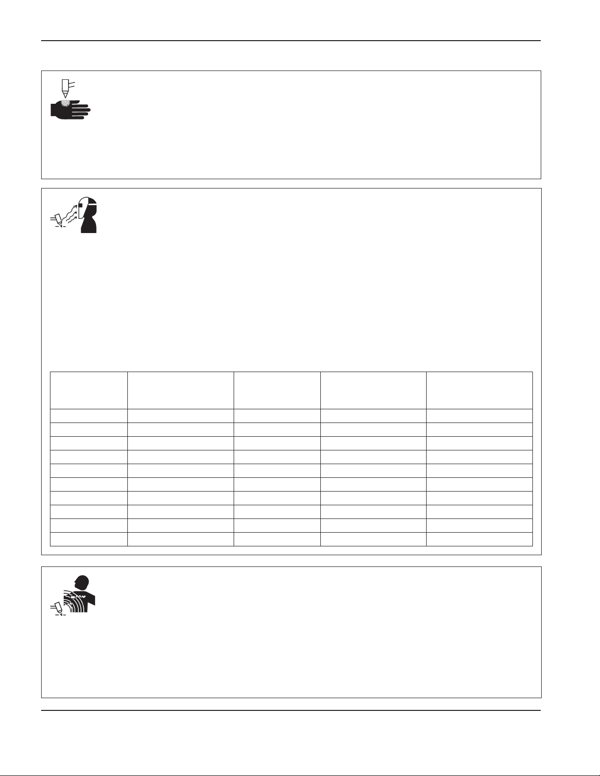
Safety
A PLASMA ARC CAN CAUSE INJURY AND BURNS
Instant-on torches
• A plasma arc ignites immediately when the torch switch is activated.
The plasma arc will cut quickly through gloves and skin.
• Keep away from the torch tip.
• Do not hold metal near the cutting path.
• Never point the torch toward yourself or others.
ARC RAYS CAN BURN EYES AND SKIN
Eye protection Plasma arc rays produce intense visible and
invisible (ultraviolet and infrared) rays that can burn eyes and skin.
• Use eye protection in accordance with applicable national and local
regulations.
• Wear eye protection (safety glasses or goggles with side shields,
and a welding helmet) with appropriate lens shading to protect your
eyes from the arc’s ultraviolet and infrared rays.
Skin protection Wear protective clothing to protect against burns
caused by ultraviolet light, sparks, and hot metal.
• Wear gauntlet gloves, safety shoes, and hat.
Minimum protective shade
number
Arc current
Less than 40 A 5 5 8 9
41 A to 60 A 6 6 8 9
61 A to 80 A 8 8 8 9
81 A to 125 A 8 9 8 9
126 A to 150 A 8 9 8 10
151 A to 175 A 8 9 8 11
176 A to 250 A 8 9 8 12
251 A to 300 A 8 9 8 13
301 A to 400 A 9 12 9 13
401 A to 800 A 10 14 10 N/A
(ANSIZ49.1:2012)
Suggested shade
number for comfort
(ANSI Z49.1:2012)
• Wear flame-retardant clothing to cover all exposed areas.
• Wear cuffless trousers to prevent entry of sparks and slag.
Also, remove any combustibles, such as a butane lighter or matches,
from your pockets before cutting.
Cutting area Prepare the cutting area to reduce reflection and
transmission of ultraviolet light:
• Paint walls and other surfaces with dark colors to reduce reflection.
• Use protective screens or barriers to protect others from flash
andglare.
• Warn others not to watch the arc. Use placards or signs.
OSHA 29CFR
1910.133(a)(5)
EN168:2002
Europe
PACEMAKER AND HEARING AID OPERATION
Pacemaker and hearing aid operation can be affected by magnetic
fields from high currents.
Pacemaker and hearing aid wearers should consult a doctor before
going near any plasma arc cutting and gouging operations.
To reduce magnetic field hazards:
• Keep both the work lead and the torch lead to one side, away from
your body.
• Route the torch leads as close as possible to the work lead.
• Do not wrap or drape the torch lead or work lead around your body.
• Keep as far away from the power supply as possible.
SC-6 Safety and Compliance
Page 23

NOISE CAN DAMAGE HEARING
Safety
Cutting with a plasma arc can exceed acceptable noise levels as
defined by local regulations in many applications. Prolonged exposure
to excessive noise can damage hearing. Always wear proper ear
protection when cutting or gouging, unless sound pressure level
measurements taken at the site have verified personal hearing
protection is not necessary per relevant international, regional,
andlocal regulations.
Significant noise reduction can be obtained by adding simple
engineering controls to cutting tables such as barriers or curtains
positioned between the plasma arc and the workstation, and/
or locating the workstation away from the plasma arc. Implement
administrative controls in the workplace to restrict access and limit
operator exposure time, and screen off noisy areas and/or take
measures to reduce reverberation in cutting areas by putting up
noiseabsorbers.
DRY DUST COLLECTION INFORMATION
In some workplaces, dry dust can represent a potential explosion
hazard.
The U.S. National Fire Protection Association’s NFPA standard 68,
“Explosion Protection by Deflagration Venting,” provides requirements
for the design, location, installation, maintenance, and use of devices
and systems to vent combustion gases and pressures after any
deflagration event. Consult with the manufacturer or installer of any dry
dust collection system for applicable requirements before you install
a new dry dust collection system or make significant changes in the
process or materials used with an existing dry dust collection system.
Consult your local “Authority Having Jurisdiction” (AHJ) to determine
whether any edition of NFPA standard 68 has been “adopted by
reference” in your local building codes.
Refer to NFPA standard 68 for definitions and explanations of
regulatory terms such as deflagration, AHJ, adopted by reference,
theKst value, deflagration index, and other terms.
Use ear protectors if the noise is disruptive or if there is a risk
of hearing damage after all other engineering and administrative
controls have been implemented. If hearing protection is required,
wear only approved personal protective equipment such as ear
muffs or ear plugs with a noise reduction rating appropriate for the
situation. Warnothers near the cutting area of possible noise hazards.
Inaddition, ear protection can prevent hot splatter from entering
theear.
Note 1 – Unless a site-specific evaluation has been completed that
determines that none of the dust generated is combustible, then
NFPA standard 68 requires the use of explosion vents. Design the
explosion vent size and type to conform to the worst-case Kst value
as described in Annex F of NFPA standard 68. NFPA standard 68
does not specifically identify plasma cutting or other thermal cutting
processes as requiring deflagration venting systems, but it does apply
these new requirements to all dry dust collection systems.
Note 2 – Users should consult and comply with all applicable national,
state, and local regulations. Publications do not intend to urge action
that is not in compliance with all applicable regulations and standards,
and this manual may never be construed as doing so.
Safety and Compliance SC-7
Page 24
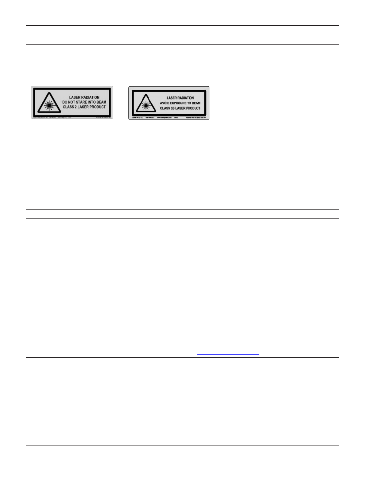
Safety
LASER RADIATION
Exposure to the laser beam from a laser pointer can result in serious eye injury. Avoid direct eye exposure.
On products that use a laser pointer for alignment, one of the following laser radiation labels has been applied on the product near where the
laser beam exits the enclosure. The maximum output (mV), wavelength emitted (nM), and, if appropriate, pulse duration are also provided.
Additional laser safety instructions:
• Consult with an expert on local laser regulations. Laser safety
training may be required.
• Do not allow untrained persons to operate the laser. Lasers can be
dangerous in the hands of untrained users.
• Do not look into the laser aperture or beam at any time.
• Position the laser as instructed to avoid unintentional eye contact.
• Do not use the laser on reflective workpieces.
• Do not use optical tools to view or reflect the laser beam.
• Do not disassemble or remove the laser or aperture cover.
ADDITIONAL SAFETY INFORMATION
1. ANSI Standard Z49.1, Safety in Welding and Cutting, American
Welding Society, 550 LeJeune Road, P.O. Box 351020,
Miami,FL 33135
2. ANSI Standard Z49.2, Fire Prevention in the Use of Cutting
and Welding Processes, American National Standards Institute,
1430Broadway, New York, NY 10018
3. ANSI Standard Z87.1, Safe Practices for Occupation and
Educational Eye and Face Protection, American National
Standards Institute, 1430 Broadway, New York, NY 10018
4. AWS F4.1, Recommended Safe Practices for the Preparation
forWelding and Cutting of Containers and Piping That Have
Held Hazardous Substances, American Welding Society,
550LeJeune Road, P.O. Box 351040, Miami, FL 33135
5. AWS F5.2, Recommended Safe Practices for Plasma Arc
Cutting, American Welding Society, 550 LeJeune Road,
P.O.Box 351040, Miami, FL 33135
• Modifying the laser or product in any way can increase the risk of
laser radiation.
• Use of adjustments or performance of procedures other than those
specified in this manual may result in hazardous laser radiation
exposure.
• Do not operate in explosive atmospheres, such as in the presence of
flammable liquids, gases, or dust.
• Use only laser parts and accessories that are recommended or
provided by the manufacturer for your model.
• Repairs and servicing must be performed by qualified personnel.
• Do not remove or deface the laser safety label.
6. CGA Pamphlet P-1, Safe Handling of Compressed Gases in
Cylinders, Compressed Gas Association, 1235 Jefferson Davis
Highway, Arlington, VA 22202
7. CSA Standard W117.2, Code for Safety in Welding and Cutting,
Canadian Standards Association Standard Sales, 178 Rexdale
Boulevard, Rexdale, Ontario M9W 1R3, Canada
8. NFPA Standard 51B, Cutting and Welding Processes, National
Fire Protection Association, 1 Batterymarch Park, Quincy, MA
02169-7471
9. NFPA Standard 70, National Electrical Code, National Fire
Protection Association, 1 Batterymarch Park, Quincy, MA
02169-7471
10. OSHA, Safety and Health Standards, 29FR 1910 U.S.
Government Printing Office, Washington, D.C. 20402
11. AWS Safety and Health Fact Sheets, American Welding Society,
550 LeJeune Road, P.O. Box 351040, Miami, FL 33135,
www. aws.org/technical/facts/
SC-8 Safety and Compliance
Page 25

Section 2
SPECIFICATIONS
In this section:
System description ....................................................................................................................................................................................2-3
General ..............................................................................................................................................................................................2-3
Power supply ....................................................................................................................................................................................2-3
Ignition console ................................................................................................................................................................................2-3
Selection console ............................................................................................................................................................................2-3
Metering console .............................................................................................................................................................................2-3
Torch ..................................................................................................................................................................................................2-3
Specifications .............................................................................................................................................................................................2-4
System gas requirements ..............................................................................................................................................................2-4
Power supply ....................................................................................................................................................................................2-5
Ignition console – 078172 ............................................................................................................................................................2-6
Torch lead junction box (Optional) – 078619 ..........................................................................................................................2-8
Selection console – 078533 ........................................................................................................................................................2-9
Metering console – 078535 ......................................................................................................................................................2-10
Torch – 228520 ........................................................................................................................................................................... 2-11
IEC symbols ............................................................................................................................................................................................. 2-12
Symbols and Marks ................................................................................................................................................................................ 2-13
HPR130XD Auto Gas – 806330 2-1
Page 26
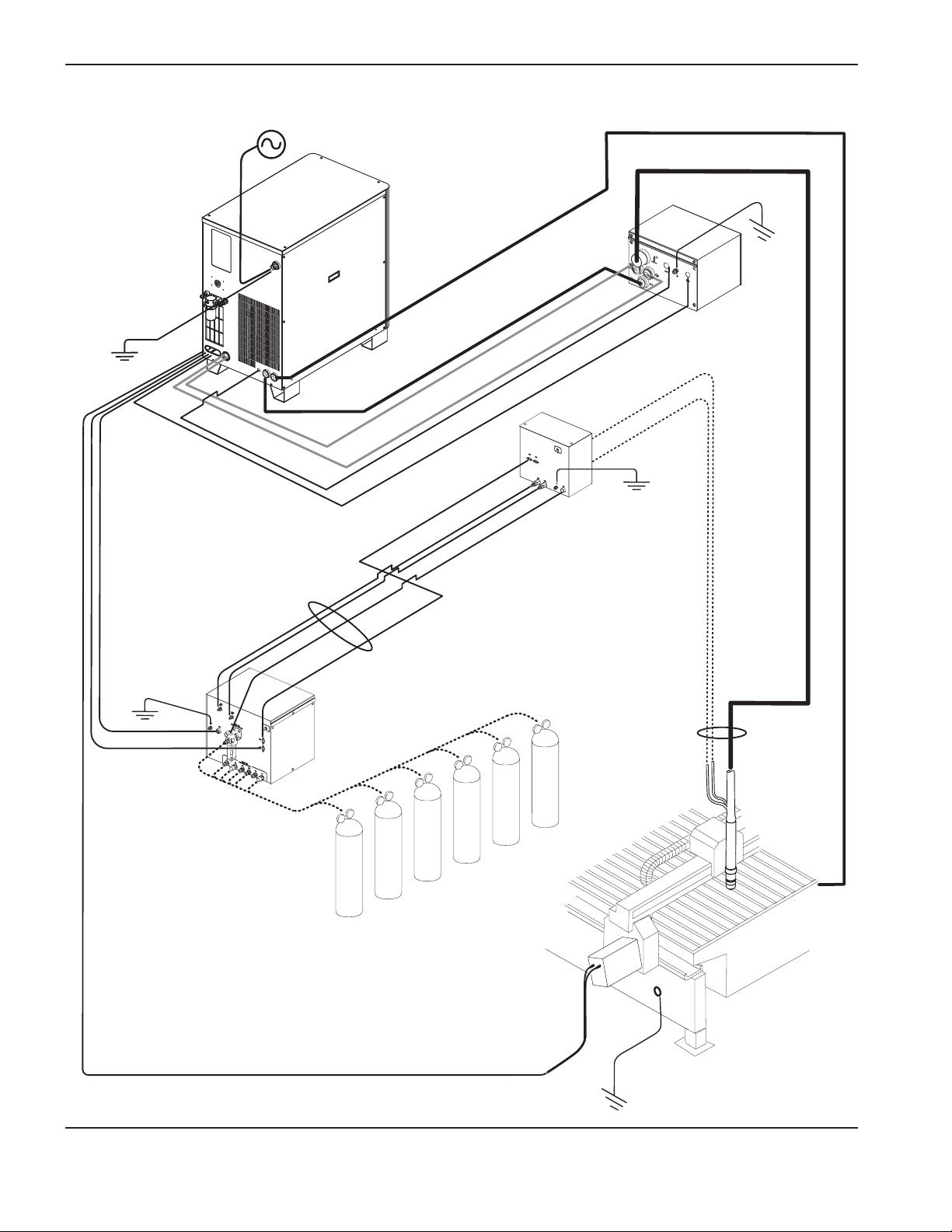
SpecificationS
2-2 HPR130XD Auto Gas – 806330
Page 27

SpecificationS
System description
General
HyPerformance plasma systems are designed to cut a wide range of thicknesses of mild steel, stainless steel
andaluminum.
Power supply
The power supply is a 130 A, 150-VDC constant-current supply. It contains the circuitry to ignite a torch, a heat
exchanger and pump to cool the torch. The power supply has a serial interface to provide communication with a CNC
controller.
Ignition console
The ignition console uses a spark-gap assembly. The ignition console converts 120 VAC control voltage from the power
supply into high-frequency and high-voltage pulses (9 –10 kV) to break over the torch electrode-nozzle gap. The highvoltage, high-frequency signal is coupled to the cathode lead and pilot arc lead.
Selection console
The selection console manages the selection and mixing of the plasma gases. It contains motor valves, solenoid valves
and pressure transducers. It also contains a PC control board, an AC relay board and a power distribution board. The
selection console has an LED lamp that illuminates when power is supplied to the system.
Metering console
The metering console may be located up to 1.8 m (6 ft) away from the torch and controls the flow rate of the gases
to the torch in real time. It also controls the gas portion of the LongLife® process. The metering console contains
proportional control valves, a PC control board and a power distribution board.
Torch
The torch can cut 12 mm mild steel at up to 2032 mm/min (1/2 inch at up to 80 ipm). The maximum production cutting
capability of the torch is 16 mm (5/8 inch) for HyDefinition and conventional cutting. Maximum pierce capability is 32
mm (1.25 inch) for mild steel and 19 mm (3/4 inch) for stainless steel and aluminum. The maximum severance capability
is 38 mm (1.5 inch) for mild steel and 25 mm (1 inch) for stainless steel and aluminum.
HPR130XD Auto Gas – 806330 2-3
Page 28
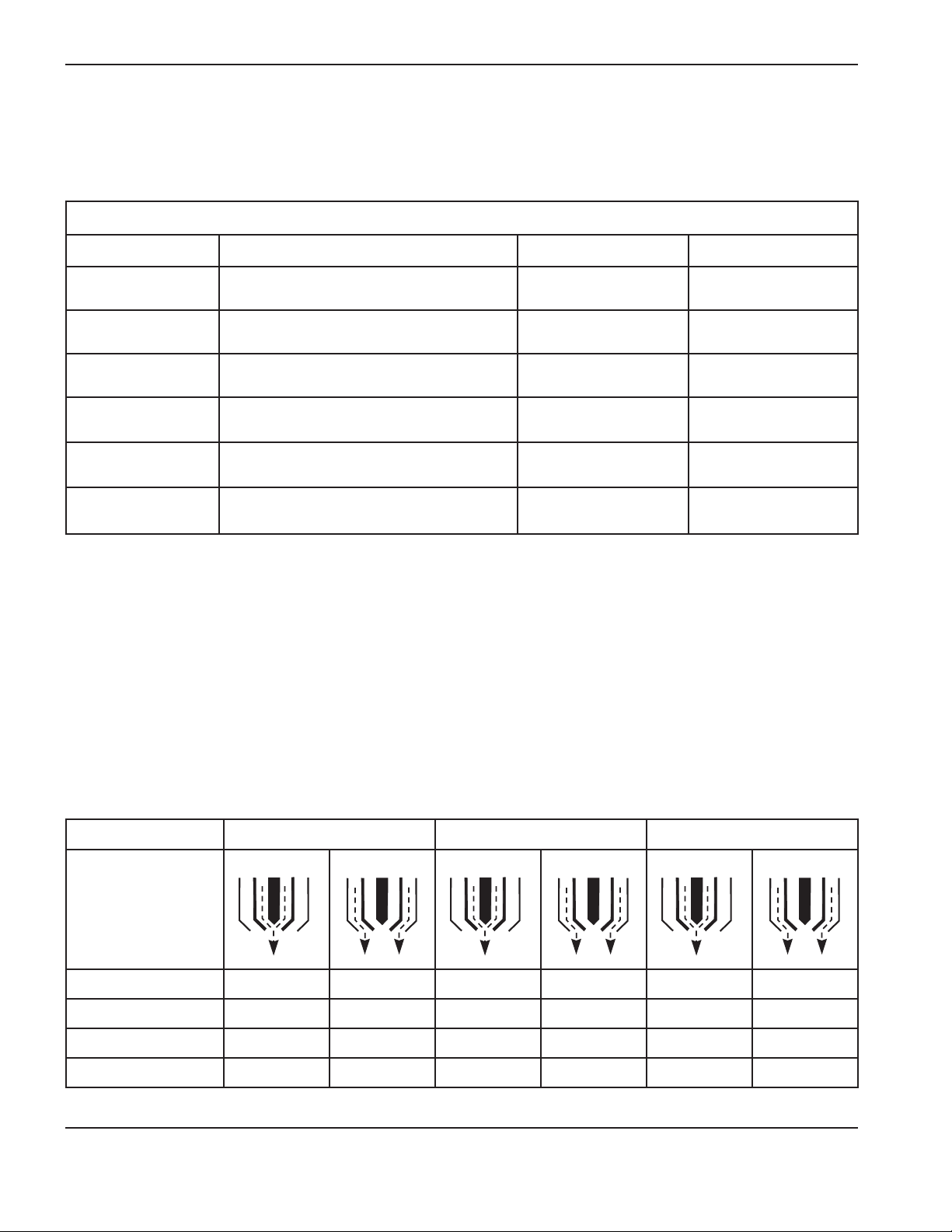
SpecificationS
Specifications
System gas requirements
Gas quality and pressure requirements
Gas type Quality Pressure +/- 10% Flow rate
O
oxygen 99.5% pure
2
Clean, dry, oil-free
N2 nitrogen 99.99% pure
Clean, dry, oil-free
Air * Clean, dry, oil-free per
ISO 8573-1 Class 1.4.2
H35
argon-hydrogen
F5
nitrogen-hydrogen
99.995% pure
(H35 = 65% Argon, 35% Hydrogen)
99.98% pure
(F5 = 95% Nitrogen, 5% Hydrogen)
Ar argon 99.99% pure
Clean, dry, oil-free
793 kPa / 8 bar
115 psi
793 kPa / 8 bar
115 psi
793 kPa / 8 bar
115 psi
793 kPa / 8 bar
115 psi
793 kPa / 8 bar
115 psi
793 kPa / 8 bar
115 psi
4250 l/h 150 scfh
7080 l/h 250 scfh
7080 l/h 250 scfh
4250 l/h 150 scfh
4250 l/h 150 scfh
4250 l/h 150 scfh
* ISO standard 8573-1 Class 1.4.2 requirements are:
•Particulates – no more than 100 particles per cubic meter of air at a Size of 0.1 to 0.5 microns in the largest
dimension and 1 particle per cubic meter of air at a Size of 0.5 to 5.0 microns in the largest
dimension.
•Water – the pressure dewpoint of the humidity must be less than or equal to 3°C (37.4°F).
•Oil – the concentration of oil can be no more than 0.1 mg per cubic meter of air.
Mild steel Stainless steel Aluminum
Gas types Plasma gas Shield gas Plasma gas Shield gas Plasma gas Shield gas
Cutting 30 to 50 A O
Cutting 80 A O
Cutting 130 A O
2
2
2
O
2
N2 & F5 N
Air F5 N
Air N2 & H35 N
2
2
2
Air Air
– –
H35 & Air N2 & Air
2-4 HPR130XD Auto Gas – 806330
Page 29
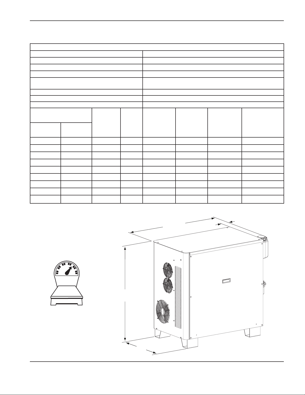
SpecificationS
Power supply
General
Maximum OCV (U
Maximum output current (I2) 130 amperes (A)
Output voltage (U2) 50 – 150 VDC
Duty cycle rating (X) 100% @ 19.5 kw, 40°C (104°F)
Ambient temperature/Duty cycle
Power factor (cosϕ) 0.88 @ 130 ADC output
Cooling Forced air (Class F)
Insulation Class H
Power supply
part numbers
Without
Hypernet
®
078538 078546 200/208 3 50/60 62/60 CSA 21.5
078539 078547 220 3 50/60 57 CSA 21.5
078540 078548 240 3 60 52 CSA 21.5
078541 078549 380* 3 50/60 33 CCC 21.5
078542 078550 400 3 50/60 32 CE/GOST-R 21.5
078603 078604 415 3 50/60 32 CE/GOST-R 21.5
078543 078551 440 3 50/60 28 CSA 21.5
078544 078552 480 3 60 26 CSA 21.5
078545 078553 600 3 60 21 CSA 21.5
* The 380 volt CCC regulatory approval only applies to 50 Hz operation
) 311 VDC
0
With
AC Voltage
(U1)
Phase
Hypernet
Power supplies will operate between -10°C and +40°C
(+14°°Fand 104°F)
Frequency
(Hz)
Amperage
(I1)
Regulatory
approval
Power kVA
(U1 x I1 x 1.73)
(+/- 10%)
317.5 kg
700 lb
967.7 mm
38.1 inch
566.4 mm
22.3 inch
1079.5 mm
42.5 inch
154.9 mm
6.1 inch
HPR130XD Auto Gas – 806330 2-5
Page 30
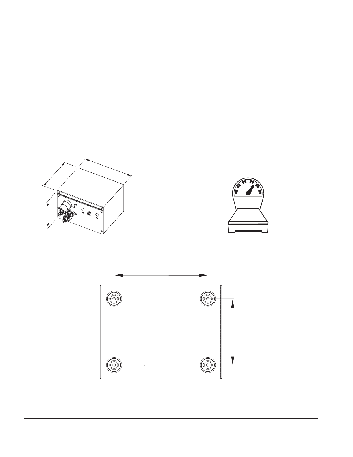
SpecificationS
Ignition console – 078172
• Theignitionconsolemaybemountedlocallyonthepowersupply(LHF)orremotelyonthecuttingtable’sbridge
(RHF). See Installation section for details.
• Maximumcablelengthfromtheignitionconsoletothetorchlifterstationis20m(65ft).Allowroomtoremove
the top for servicing.
• Theignitionconsolemaybemountedhorizontallyorvertically.
283 mm
219 mm
8.625 inch
11.125 inch
194 mm
7.625 inch
9.1 kg
20 lb
216 mm
8.5 inch
152 mm
6 inch
2-6 HPR130XD Auto Gas – 806330
Page 31

LHF mounting (local)
SpecificationS
RHF mounting (remote)
Mounted on table
Horizontal mounting
Vertical mounting
HPR130XD Auto Gas – 806330 2-7
Page 32
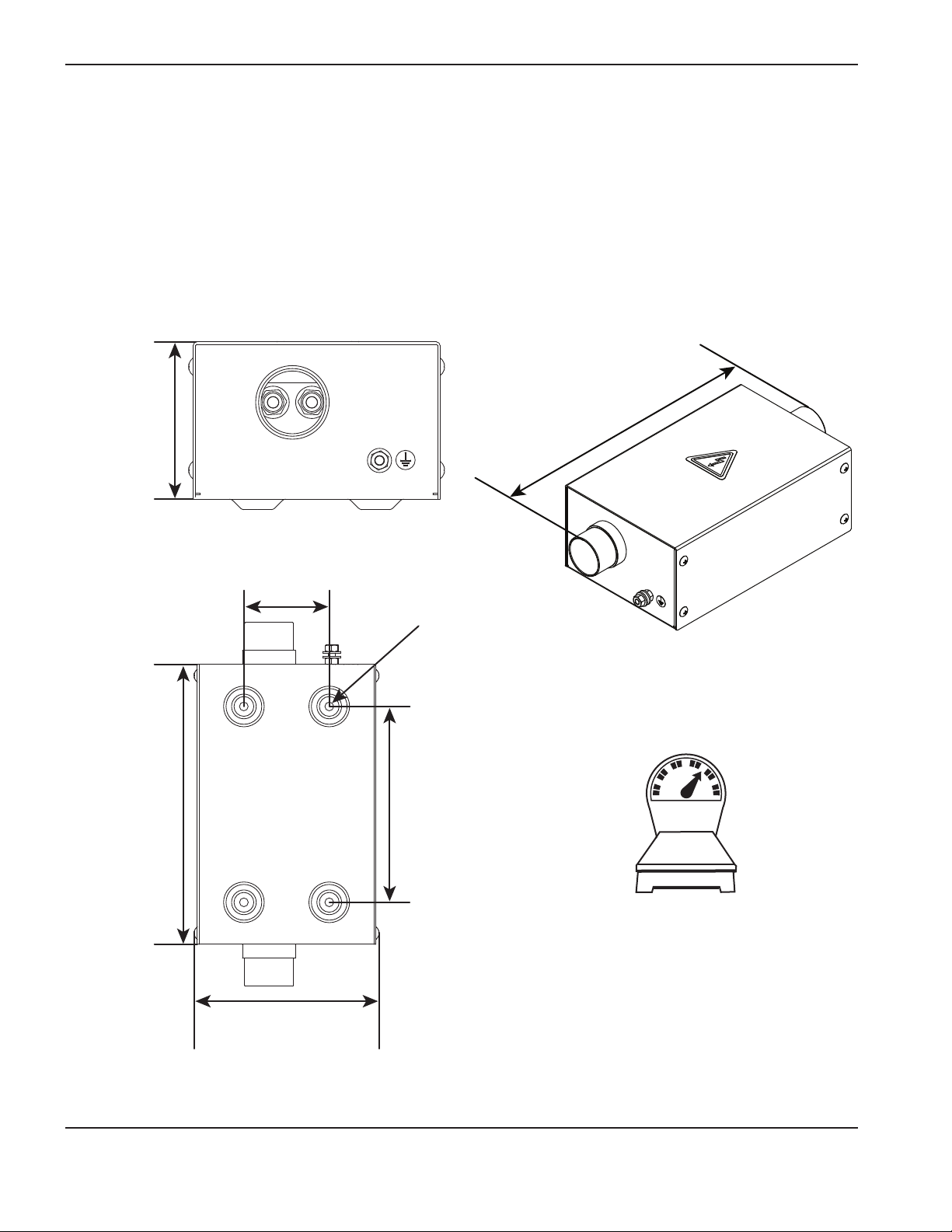
SpecificationS
Torch lead junction box (Optional) – 078619
• The junction box provides increased installation flexibility by creating a break point in the leads between the
ignition console and torch to facilitate easier replacement of torch leads in certain applications.
• Maximum combined lead length from the ignition console to the torch must be less than or equal to:
• 20 m (65 feet) for HPR130XD / HPR260XD
• 15 m (50 feet) for HPR400XD / HPR800XD
109 mm
4.33 inch
254 mm
10.0 inch
330 mm
13.0 inch
77.5 mm
3.05 inch
7.9 mm
0.31 inch
178 mm
7.00 inch
4.6 kg
10.2 lb
165 mm
6.5 inch
2-8 HPR130XD Auto Gas – 806330
Page 33
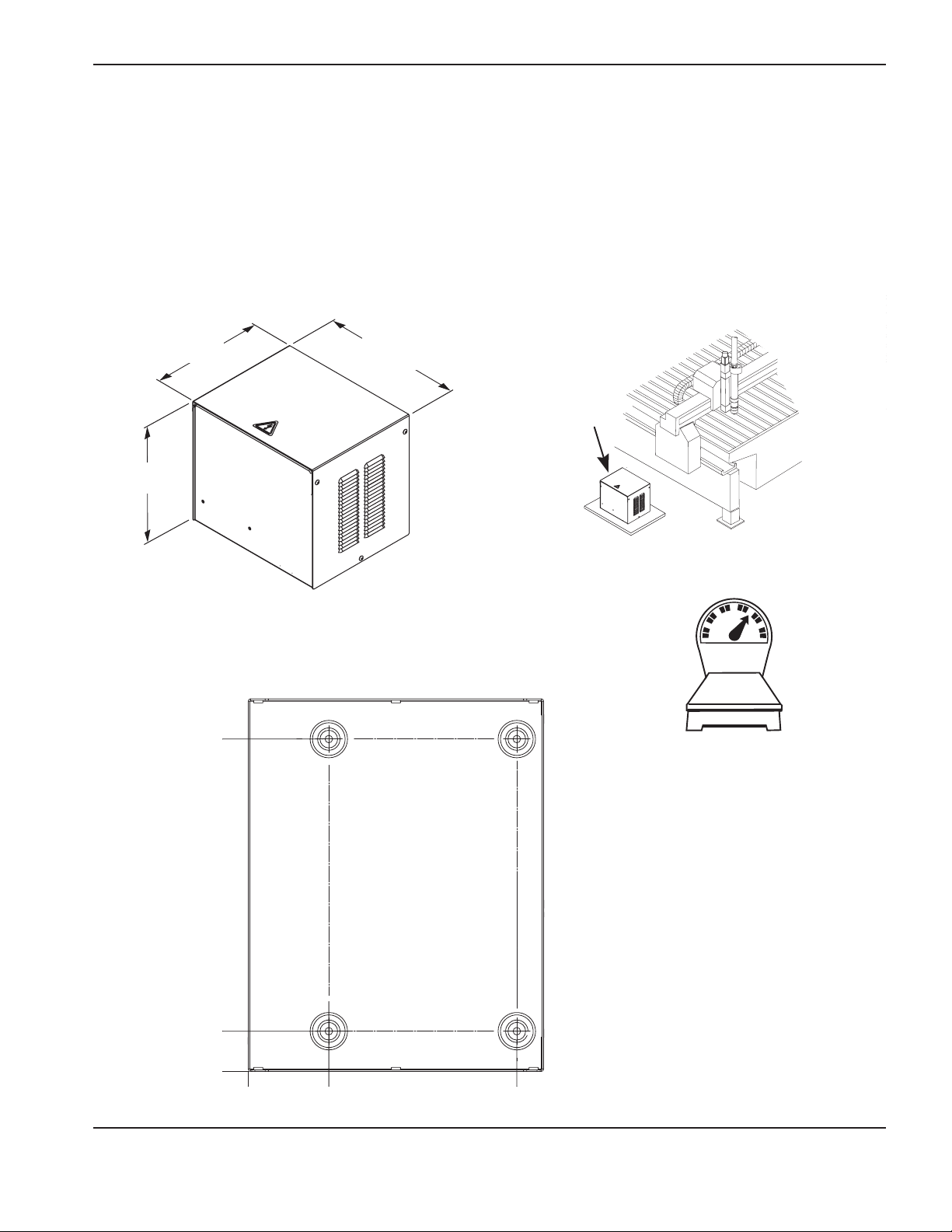
SpecificationS
Selection console – 078533
• Maximum cable length from the power supply to the selection console is 75 m (250 ft).
• Maximum cable length from the selection console to the metering console is 20 m (65 ft).
• MounttheselectionconsoleontopofthepowersupplyorneartheCNConthecuttingtable.Allowroomto
open the top for servicing.
285.75 mm
11.25 inch
311.15 mm
12.25 inch
314.5 mm
12.38 inch
355.6 mm
14.00 inch
13.6 kg
30 lb
38.1 mm
1.5 inch
0
0
76.2 mm
3.0 inch
254.0 mm
10.0 inch
HPR130XD Auto Gas – 806330 2-9
Page 34
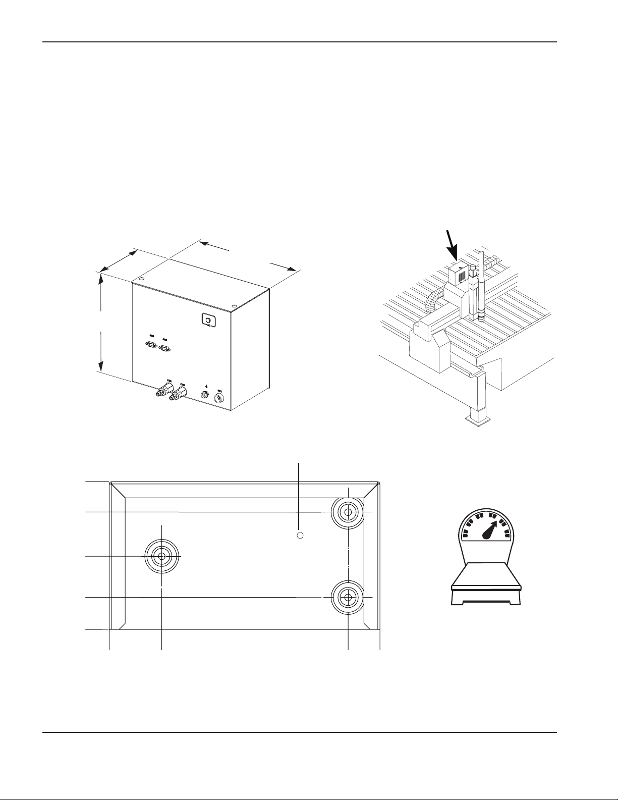
SpecificationS
Metering console – 078535
• Maximumcablelengthfromthemeteringconsoletothetorchlifterstationis1.8m(6ft).
• Mountthemeteringconsoletothetorchcarriageonlargertables.Onsmallertablesitcanbemountedtoa
bracket just above the bridge.
• The vent hole on the console must be kept clear at all times.
153.9 mm
6.1 inch
122.2 mm
4.8 inch
155.58 mm
6.125 inch
263.53 mm
10.375 inch
285.75 mm
11.25 inch
Vent hole. Do not block.
76.2 mm
3.0 inch
33.3 mm
1.3 inch
0
0
54.9 mm
2.2 inch
248.9 mm
9.8 inch
282.5 mm
11.1 inch
6.4 kg
14 lb
2-10 HPR130XD Auto Gas – 806330
Page 35
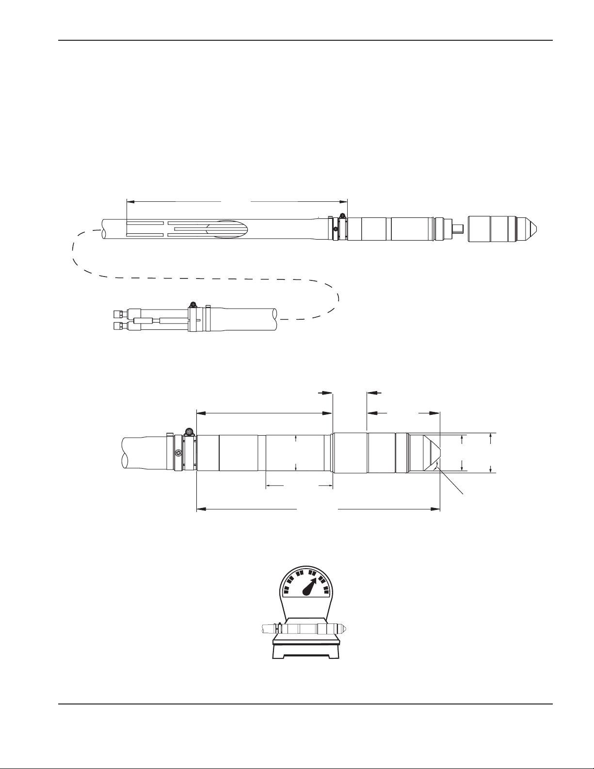
Torch – 228520
• Theoutsidediameterofthetorchmountingsleeveis50.8mm(2.0inches).
• Theminimumbendradiusforthetorchleadsis152.4mm(6.0inches).
1.8 m
6 ft
SpecificationS
193 mm
7.59 inch
51 mm
2.00 inch
95 mm
3.74 inch
13.60 inch
1.9 kg
4.2 lb
345 mm
49 mm
1.91 inch
104 mm
4.10 inch
51 mm
2 inch
43°
57 mm
2.25 inch
HPR130XD Auto Gas – 806330 2-11
Page 36
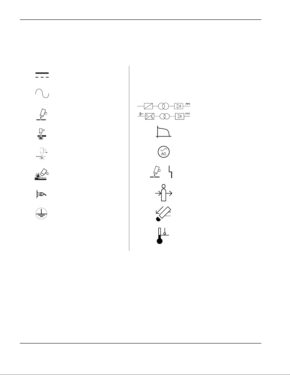
SpecificationS
IEC symbols
The following symbols may appear on the power supply data plate, control labels, switches, LEDs, and LCD screen.
Direct current (DC)
Alternating current (AC)
Plasma torch cutting
Plate metal cutting
Expanded metal cutting
Gouging
AC input power connection
l
O
1~
f
1
f
2
Power is ON
Power is OFF
An inverter-based power
source, either 1-phase or
3-phase
Volt/amperage curve, “drooping” characteristic
AC
Power is ON (LED)
System fault (LED)
Inlet gas pressure fault (LCD)
The terminal for the external
protective (earth) conductor
Missing or loose consumables
(LCD)
Power supply is out of
temperature range (LCD)
2-12 HPR130XD Auto Gas – 806330
Page 37
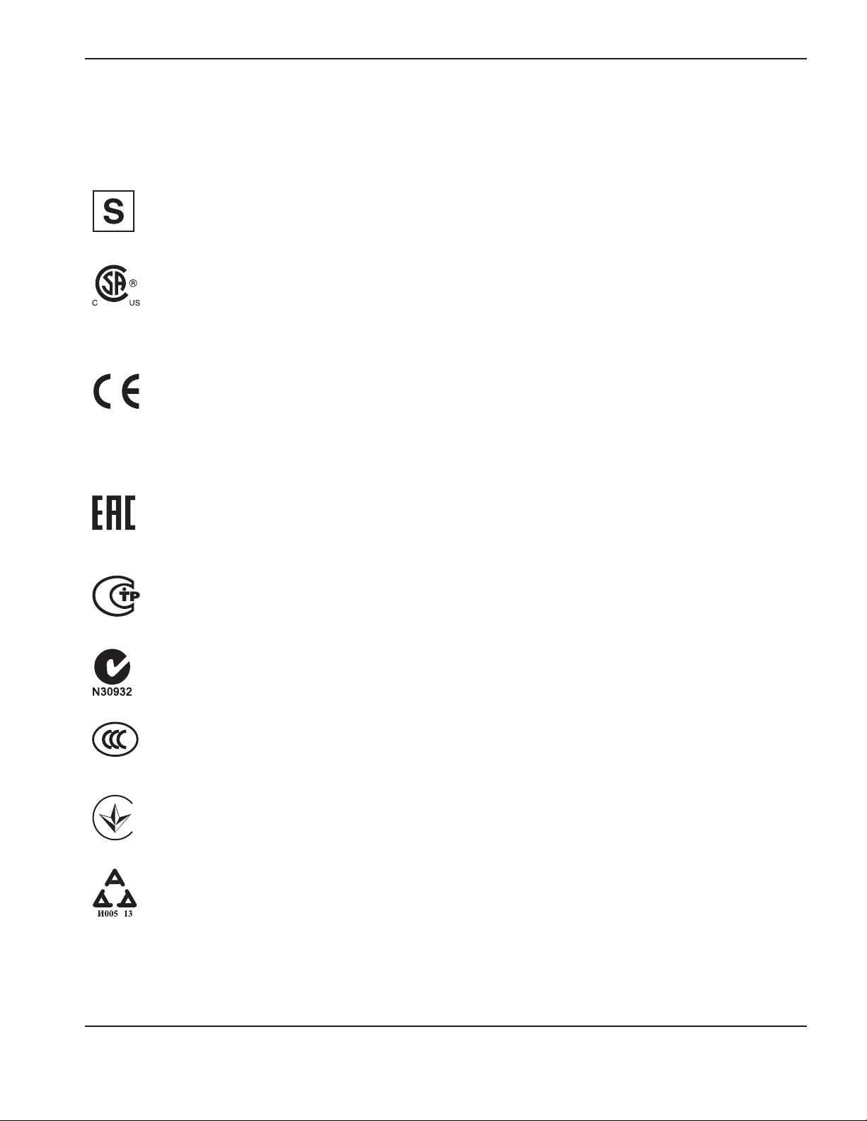
Symbols and Marks
Your product may have one or more of the following markings on or near the data plate. Due to differences and conflicts
in national regulations, not all marks are applied to every version of a product.
SpecificationS
S mark
The S mark indicates that the power supply and torch are suitable for operations carried out in environments
with increased hazard of electrical shock according to IEC 60974-1.
CSA mark
Products with a CSA mark meet the United States and Canadian regulations for product safety. The products
were evaluated, tested, and certified by CSA-International. Alternatively, the product may have a mark by one
of the other Nationally Recognized Testing Laboratories (NRTL) accredited in both the United States and
Canada, such as Underwriters Laboratories, Incorporated (UL) or TÜV.
CE mark
The CE marking signifies the manufacturer’s declaration of conformity to applicable European directives and
standards. Only those versions of products with a CE marking located on or near the data plate have been
tested for compliance with the European Low Voltage Directive and the European Electromagnetic
Compatibility (EMC) Directive. EMC filters needed to comply with the European EMC Directive are
incorporated within versions of the product with a CE marking.
Eurasian Customs Union (CU) mark
CE versions of products that include an EAC mark of conformity meet the product safety and EMC
requirements for export to Russia, Belarus, and Kazakhstan.
GOST-TR mark
CE versions of products that include a GOST-TR mark of conformity meet the product safety and EMC
requirements for export to the Russian Federation.
C-Tick mark
CE versions of products with a C-Tick mark comply with the EMC regulations required for sale in Australia
and New Zealand.
CCC mark
s
The China Compulsory Certification (CCC) mark indicates that the product has been tested and found
compliant with product safety regulations required for sale in China.
UkrSEPRO mark
The CE versions of products that include a UkrSEPRO mark of conformity meet the product safety and EMC
requirements for export to the Ukraine.
Serbian AAA mark
CE versions of products that include a AAA Serbian mark meet the product safety and EMC requirements for
export to Serbia.
HPR130XD Auto Gas – 806330 2-13
Page 38

SpecificationS
2-14 HPR130XD Auto Gas – 806330
Page 39

Section 3
INSTALLATION
In this section:
Upon receipt ...............................................................................................................................................................................................3-3
Claims ...........................................................................................................................................................................................................3-3
Installation requirements...........................................................................................................................................................................3-3
Noise levels .................................................................................................................................................................................................3-3
Placement of system components .........................................................................................................................................................3-3
Torque specifications .....................................................................................................................................................................3-3
Installation requirements...........................................................................................................................................................................3-4
System components .......................................................................................................................................................................3-5
Cables and hoses ...........................................................................................................................................................................3-5
Supply gas hoses ............................................................................................................................................................................3-5
Customer-supplied power cable .................................................................................................................................................3-5
Recommended grounding and shielding practices ...........................................................................................................................3-6
Introduction .................................................................................................................................................................................................3-6
Types of grounding .........................................................................................................................................................................3-6
Grounding practices .......................................................................................................................................................................3-6
Grounding diagram .........................................................................................................................................................................3-9
Placement of the power supply ........................................................................................................................................................... 3-11
Install the ignition console .....................................................................................................................................................................3-12
Install the metering console .................................................................................................................................................................. 3-14
Placement of the selection console ....................................................................................................................................................3-15
Power supply to ignition console leads ............................................................................................................................................. 3-16
Pilot arc lead .................................................................................................................................................................................. 3-16
Negative lead .................................................................................................................................................................................3-16
Ignition console power cable ..................................................................................................................................................... 3-18
Ignition console coolant hoses .................................................................................................................................................. 3-19
Power supply to selection console cables ........................................................................................................................................3-20
Control cable ................................................................................................................................................................................. 3-20
Power cable ................................................................................................................................................................................... 3-20
Selection console to metering console connections......................................................................................................................3-22
Cable and gas hose assembly .................................................................................................................................................. 3-22
Power supply to CNC interface cable ............................................................................................................................................... 3-24
Optional multi-system CNC interface cable .......................................................................................................................... 3-24
Notes to CNC interface cable run list ..................................................................................................................................... 3-25
HPR130XD Auto Gas – 806330 3-1
Page 40

InstallatIon
Examples of output circuits ........................................................................................................................................................ 3-26
Examples of input circuits ........................................................................................................................................................... 3-27
Remote ON/OFF switch (provided by customer) ........................................................................................................................... 3-28
Torch lead assembly ..............................................................................................................................................................................3-29
Torch lead junction box (Optional)......................................................................................................................................................3-30
Install the junction box ................................................................................................................................................................. 3-31
Work lead .................................................................................................................................................................................................3-36
Torch connections .................................................................................................................................................................................. 3-37
Connect the torch to the torch lead assembly ...................................................................................................................... 3-37
Connect the torch to the quick-disconnect ........................................................................................................................... 3-41
Torch mounting and alignment ............................................................................................................................................................3-42
Mounting the torch ....................................................................................................................................................................... 3-42
Torch alignment ............................................................................................................................................................................3-42
Torch lifter requirement .........................................................................................................................................................................3-43
Hypernet....................................................................................................................................................................................................3-43
Power requirements ............................................................................................................................................................................... 3-44
General ........................................................................................................................................................................................... 3-44
Line disconnect switch ...............................................................................................................................................................3-45
Main power cable ......................................................................................................................................................................... 3-45
Connect the power .................................................................................................................................................................................3-46
Torch coolant requirements ..................................................................................................................................................................3-47
Premixed coolant for standard operating temperatures ...................................................................................................... 3-47
Custom Coolant mix for cold operating temperatures .........................................................................................................3-48
Custom Coolant mix for hot operating temperatures ...........................................................................................................3-49
Water purity requirements .................................................................................................................................................................... 3-49
Fill the power supply with coolant .......................................................................................................................................................3-50
Gas requirements ...................................................................................................................................................................................3-51
Setting the supply regulators .....................................................................................................................................................3-51
Gas regulators ......................................................................................................................................................................................... 3-52
Supply gas plumbing .............................................................................................................................................................................3-53
Connect the supply gases .........................................................................................................................................................3-54
Supply gas hoses ...................................................................................................................................................................................3-55
3-2 HPR130XD Auto Gas – 806330
Page 41

InstallatIon
Upon receipt
• Verifythatallsystemcomponentsonyourorderhavebeenreceived.Contactyoursupplierifanyitems
are missing.
• Inspectthesystemcomponentsforanyphysicaldamagethatmayhaveoccurredduringshipping.Ifthereis
evidence of damage, refer to Claims. All communications regarding claims must include the model number and
serial number located on the rear of the power supply.
Claims
Claims for damage during shipment – If your unit was damaged during shipment, you must file a claim with the
carrier. Hypertherm will furnish you with a copy of the bill of lading upon request. If you need additional assistance, call
Customer Service listed in the front of this manual, or your authorized Hypertherm distributor.
Claims for defective or missing merchandise – If any of the merchandise is defective or missing, contact your
supplier. If you need additional assistance, call Customer Service listed in the front of this manual, or your authorized
Hypertherm distributor.
Installation requirements
All installation and service of the electrical and plumbing systems must conform to national and local
electrical and plumbing codes. This work should be performed only by qualified, licensed personnel.
Direct any technical questions to the nearest Hypertherm Technical Service Department listed in the front of this manual,
or your authorized Hypertherm distributor.
Noise levels
Acceptable noise levels as defined by national and local codes may be exceeded by this plasma system. Always
wear proper ear protection when cutting or gouging. Any noise measurements taken are dependant on the specific
environment in which the system is used. See also Noise can damage hearing in the Safety section of this manual.
Specific information by product can be found in the Hypertherm downloads library at:
https://www.hypertherm.com/Xnet/library/DocumentLibrary.jsp
Select the product you are looking for from the Product Type drop down menu, choose “Regulatory” from the Category
drop down menu, and choose “Acoustical Noise Data Sheets” from the Sub Category drop down menu. Hit Submit.
Placement of system components
• Placeallsystemcomponentsinpositionpriortomakingelectrical,gas,andinterfaceconnections.Usethe
diagram in this section for component-placement guidelines.
• Groundallsystemcomponentstoearth.SeeRecommended grounding and shielding practices in this section
for details.
• Topreventleaksinthesystem,tightenallgasandwaterconnectionsasshownbelow:
Torque specifications
Gas or water hose
size kgf-cm lbf-in. lbf-ft
Up to 10 mm (3/8 in.) 8.6-9.8 75-85 6.25-7
12 mm (1/2 in.) 41.5-55 360-480 30-40
HPR130XD Auto Gas – 806330 3-3
Page 42

InstallatIon
4
7
Installation requirements
16
A
B
2
3
C
1
11
15
6
5
D
13
13
12
14
15
10
E
8
9
3-4 HPR130XD Auto Gas – 806330
Page 43

System components
3
4
5
6
7
8
9
Power supply
A
Ignition console
B
C
Metering console
Selection consolee
D
Torch
E
Cables and hoses
Pilot arc lead
1
Negative lead
2
Ignition console power cable
InstallatIon
Ignition console coolant hoses
Gas control cable
Gas power cable
Selection console to metering console hose and lead assembly
CNC interface cable
Optional CNC interface cable for systems with multiple power supplies
10
Torch lead assembly
11
Work lead
Supply gas hoses
12
Oxygen
13
Nitrogen or argon
14
Air
15
Argon-hydrogen (H35) or nitrogen-hydrogen (F5)
Customer-supplied power cable
16
Main power cable
HPR130XD Auto Gas – 806330 3-5
Page 44

InstallatIon
Recommended grounding and shielding practices
Introduction
This section describes practices for grounding and shielding to protect a plasma cutting system against radio frequency
interference (RFI) and electromagnetic interference (EMI) (also called
and the service ground. The diagram at the end of this section shows these types of grounds in a plasma cutting
system.
Types of grounding
Service ground
incoming line voltage. It prevents a shock hazard to any personnel from any of the equipment or the cutting table. It
includes the service ground coming into the plasma system and other systems such as the CNC and the motor drives,
as well as the supplemental ground rod connected to the cutting table. In the plasma circuits, the ground is carried from
the plasma system chassis to the chassis of each separate console through the interconnecting cables.
DC power ground
current from the torch back to the plasma system. It requires that the positive lead from the plasma system be firmly
connected to the cutting table ground bus with a properly sized cable. It also requires that the slats, on which the
workpiece rests, make firm contact with the table and the workpiece.
RFI and EMI grounding and shielding
the plasma and motor drive systems. It also limits the amount of noise that is received by the CNC and other control
and measurement circuits. The grounding practices described in this section mainly target RFI and EMI grounding
andshielding.
Grounding Practices
(6 AWG) welding cables (047040) for the EMI ground cables shown on the
ELECTRIC SHOCK CAN KILL
Disconnect electrical power before performing any maintenance.
All work requiring the removal of the plasma system cover must be performed by a
qualified technician.
See the Safety section of your manual for more safety precautions.
Recommended grounding and shielding practices
WARNING!
Introduction
noise). It also describes the DC power ground
Types of grounding
Note: The grounding practices in this section have been used on many installations with excellent results, and
Grounding practices
Hypertherm recommends that these practices be a routine part of the installation process. The actual
methods used to implement these practices may vary from system to system, but should remain as
consistent as possible. However, due to the variation in equipment and installations, these grounding
practices may not succeed in every case to eliminate RFI/EMI noise issues.
(also called safety ground or potential earth (PE) ground) is the grounding system that applies to the
(also called cutting current ground) is the grounding system that completes the path of the cutting
is the grounding system that limits the amount of electrical noise emitted by
1. Unless noted, use only 13.3 mm
diagram at the end of this section.
2. The cutting table is used for the common, or star, EMI ground point and should have threaded studs welded
to the table with a copper bus bar mounted on them. A separate bus bar should be mounted on the gantry
as close to each motor as possible. If there are motors at each end of the gantry, run a separate EMI ground
2
3-6 HPR130XD Auto Gas – 806330
Page 45

InstallatIon
cable from the far motor to the gantry bus bar. The gantry bus bar should have a separate, heavy EMI ground
communication signals, between plasma systems in multi-drop connections, and for interconnections between
the cutting table for mounting the ground bus, no other aluminum or steel hardware can be used in the ground
For a system with an RHF console, the ignition console should be mounted as closely as possible to the torch,
cable 21.2 mm2 (4 AWG; 047031) to the table bus bar. The EMI ground cables for the torch lifter and the
RHF console must each run separately to the table ground bus.
3. A ground rod that meets all applicable local and national electrical codes must be installed within 6 m (20 ft)
of the cutting table. This is a PE ground and should be connected to the cutting table ground bus bar using
13.3 mm2 (6 AWG) green and yellow grounding cable (047121) or equivalent.
4. For the most effective shielding, use the Hypertherm CNC interface cables for I/O signals, serial
all parts of the Hypertherm system.
5. All hardware used in the ground system must be brass or copper. While you can use steel studs welded to
system.
6. AC power, PE, and service grounds must be connected to all equipment according to local and national
codes.
7. For a system with a remote high frequency console (RHF), the positive, negative, and pilot arc leads should
be bundled together for as long a distance as possible. The torch lead, work lead, and the pilot arc (nozzle)
leads may be run parallel to other wires or cables only if they are separated by at least 150 mm (6 inches).
Ifpossible, run power and signal cables in separate cable tracks.
8.
and must have a separate ground cable that connects directly to the cutting table ground bus bar.
9. Each Hypertherm component, as well as any other CNC or motor drive cabinet or enclosure, must have a
separate ground cable to the common (star) ground on the table. This includes the ignition console, whether
itis bolted to the plasma system or to the cutting table.
10. The metal braided shield on the torch lead must be connected fi rmly to the ignition console and to the torch.
It must be electrically insulated from any metal and from any contact with the fl oor or building. The torch lead
can be run in a plastic cable tray or track, or covered with a plastic or leather sheath.
11. The torch holder and the torch breakaway mechanism – the part mounted to the lifter, not the part mounted
to the torch – must be connected to the stationary part of the lifter with copper braid at least 12.7 mm
(0.5inches) wide. A separate cable must run from the lifter to the gantry ground bus bar. The valve assembly
should also have a separate ground connection to the gantry ground bus bar.
12. If the gantry runs on rails that are not welded to the table, then each rail must be connected with a ground
cable from the end of the rail to the table. The rail ground cables connect directly to the table and do not need
to connect to the table ground bus bar.
13. If you are installing a voltage divider board, mount it as closely as possible to where the arc voltage is
sampled. One recommended location is inside the plasma system enclosure. If a Hypertherm voltage divider
board is used, the output signal is isolated from all other circuits. The processed signal should be run in
twisted shielded cable (Belden 1800F or equivalent). Use a cable with a braided shield, not a foil shield.
Connect the shield to the chassis of the plasma system and leave it unconnected at the other end.
14. All other signals (analog, digital, serial, and encoder) should run in twisted pairs inside a shielded cable.
Connectors on these cables should have a metal housing. The shield, not the drain, should be connected to
the metal housing of the connector at each end of the cable. Never run the shield or the drain through the
connector on any of the pins.
HPR130XD Auto Gas – 806330 3-7
Page 46

InstallatIon
1
2
3
4
1
2
5 6
7
1 Gantry ground bus
2 Ground rod
3 Plasma system lead (+)
4 Remote high frequency (RHF) console
5 CNC enclosure
6 Torch holder
7 Plasma system chassis
1 Cable to the cutting table ground bus
2 Ground cables from components on the gantry
3-8 HPR130XD Auto Gas – 806330
Page 47

Grounding diagram
The following diagram shows an example of grounding the components in a plasma cutting system.
2
3
4
5
6
789
Grounding diagram
11
InstallatIon
10
12
1
Chassis and RFI ground
AC earth ground
1 Cutting table
2 Gantry
3 Plasma system
4 Table ground bus bar
5 Gantry ground bus bar
6 Torch height control lifter (ArcGlide®, Sensor™
THC, Sensor PHC, or other)
7 RHF console (not on all systems). Connect to
table ground bus bar.
13
8, 9 System-specific component such as metering
console, gas console, or selection console
10 CNC chassis
11 Torch height control module (ArcGlide,
Command® THC)
12 System-specific component such as a cooler or
chiller
13 DC power ground
HPR130XD Auto Gas – 806330 3-9
Page 48

InstallatIon
3-10 HPR130XD Auto Gas – 806330
Page 49
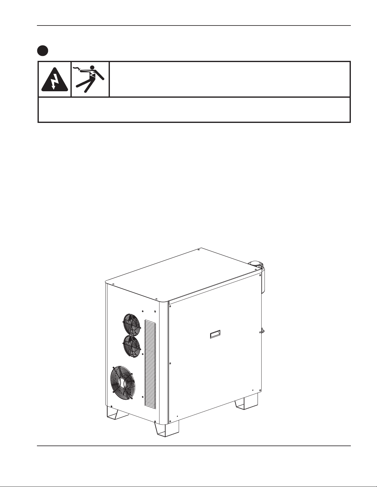
InstallatIon
Placement of the power supply
A
DANGER
ELECTRIC SHOCK CAN KILL
Remove all electrical connections to the power supply before moving or positioning. Transporting the
unit can cause personal injury and equipment damage.
The power supply can be moved by forklift but the forks must be long enough to extend the entire length of the base.
Take care when lifting so that the underside of the power supply is not damaged. The forks must also be centered front
to back and side to side to prevent tipping while moving. Fork lift speeds should be kept to a minimum, especially when
making a turn or going around a corner.
• Place the power supply in an area that is free of excessive moisture, has proper ventilation and is relatively clean.
Allow 1 m (3 ft) of space on all sides of the power supply for ventilation and service.
• Coolingairisdrawninthroughthefrontpanelandisexhaustedthroughtherearoftheunitbyacooling
fan. Donot place any filter device over the air intake locations, which reduces cooling efficiency and VOIDS
THEWARRANTY.
• Donotplacethepowersupplyonaninclinegreaterthan10°topreventitfromtoppling.
HPR130XD Auto Gas – 806330 3-11
Page 50
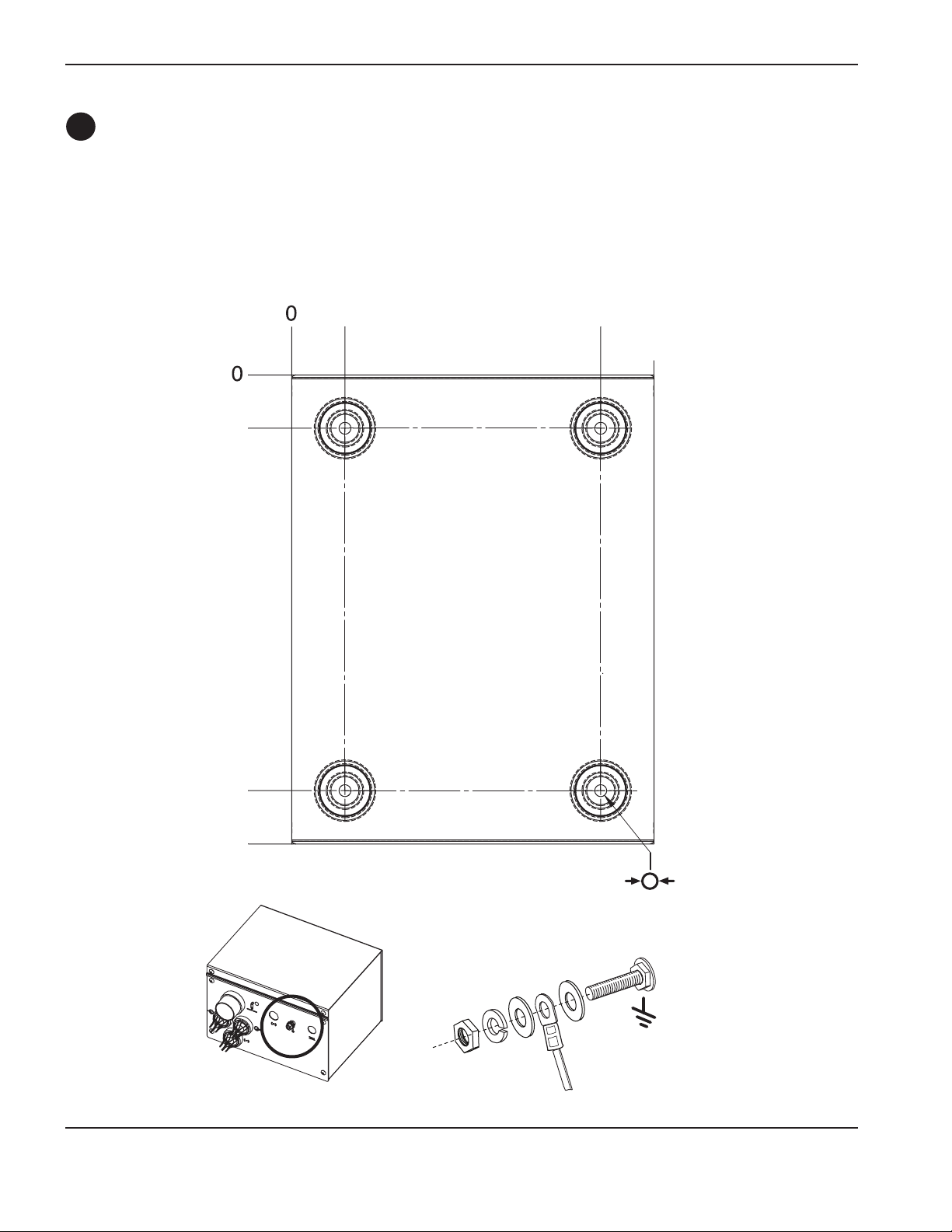
InstallatIon
B
Install the ignition console
• Mount the ignition console on the gantry (bridge) for the RHF configuration.
• Mount the ignition console on the power supply for the LHF configuration.
• Allow room to remove the top for servicing.
32 mm
1.25 inch
32 mm
1.25 inch
184 mm
7.25 inch
216 mm
8.50 inch
248 mm
9.75 inch
279 mm
11.00 inch
7 mm
0.28 inch
(4 places)
Ignition console grounding
3-12 HPR130XD Auto Gas – 806330
Page 51
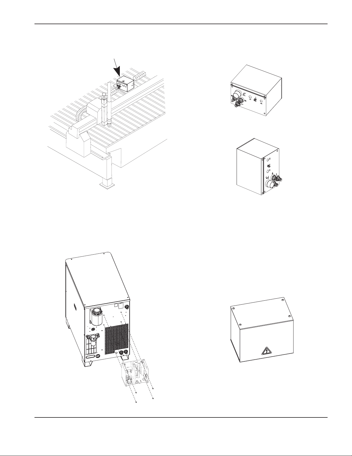
InstallatIon
Horizontal RHF mounting
Vertical RHF mounting
LHF mounting
HPR130XD Auto Gas – 806330 3-13
Page 52
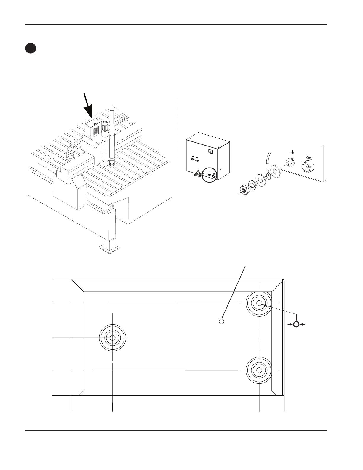
InstallatIon
Install the metering console
C
• Mount the metering console near the torch lifter station. The maximum length of the gas hoses between the
metering console and the torch is 1.8 m (6 ft).
153.9 mm
6.1 inch
122.2 mm
4.8 inch
76.2 mm
3.0 inch
33.3 mm
1.3 inch
Metering console grounding
Vent hole:
Do not block
7 mm
0.28 inch
(4 places)
0
0
54.9 mm
2.2 inch
248.9 mm
9.8 inch
282.5 mm
11.1 inch
3-14 HPR130XD Auto Gas – 806330
Page 53
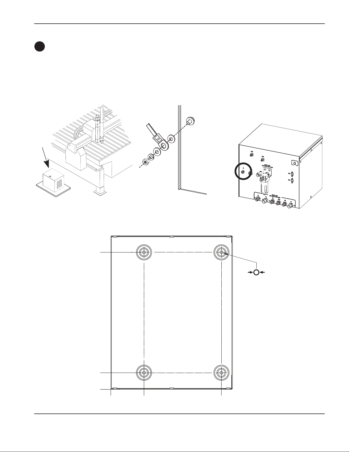
InstallatIon
D
Placement of the selection console
• Mount the selection console near the cutting table. Allow room to remove the top and right side cover for
servicing. Preferred orientation is shown in the figure below. The maximum length of cables between the power
supply and selection console is 75 m (250 ft). The maximum length of cables and hoses between the selection
console and the metering console assembly is 20 m (65 ft).
Preferred selection
console orientation
314.5 m
12.38 inch
Selection console grounding
7 mm
0.28 inch
(4 places)
38.1 mm
1.5 inch
0
0
76.2 mm
3.0 inch
254.0 mm
10.0 inch
HPR130XD Auto Gas – 806330 3-15
Page 54
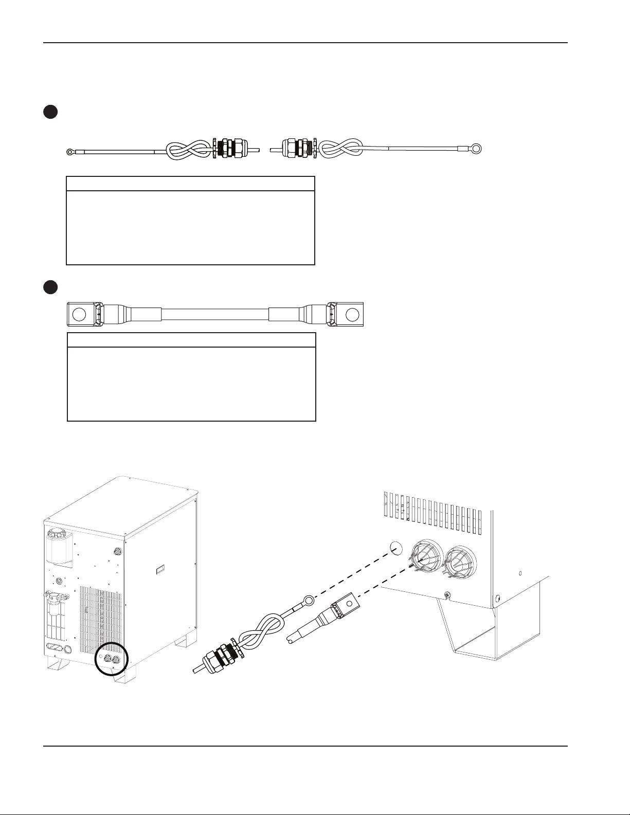
InstallatIon
1
Power supply to ignition console leads
Pilot arc lead
Ignition console
Part no. Length Part no. Length
123683* 1.5 m (5 ft) 123823 20 m (65 ft)
123820 3 m (10 ft) 123735 25 m (82 ft)
123821 4.5 m (15 ft) 123668 35 m (115 ft)
123666 7.5 m (25 ft) 123669 45 m (150 ft)
123822 10 m (35 ft) 123824 60 m (200 ft)
123667 15 m (50 ft) 123825 75 m (250 ft)
Negative lead
2
Ignition console
Part no. Length Part no. Length
123702* 1.5 m (5 ft) 123815 20 m (65 ft)
123661 3 m (10 ft) 123734 25 m (82 ft)
123813 4.5 m (15 ft) 123664 35 m (115 ft)
123662 7.5 m (25 ft) 123665 45 m (150 ft)
123814 10 m (35 ft) 123778 60 m (200 ft)
123663 15 m (50 ft) 123779 75 m (250 ft)
Power supply
I/O board
* Cable numbers 123683 and 123702 are for use with systems that have the ignition console mounted on the power supply
Pilot arc lead
Negative lead
3-16 HPR130XD Auto Gas – 806330
Page 55
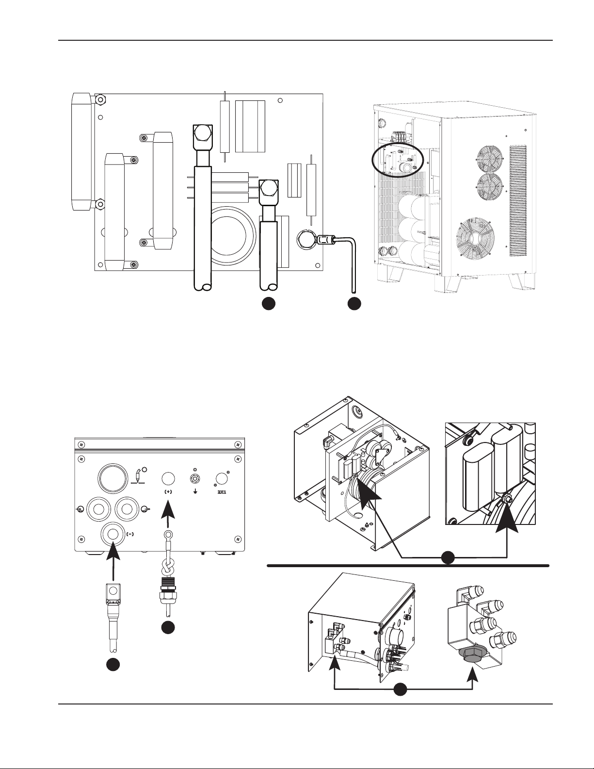
InstallatIon
1
Work lead
2
Pilot arc leadNegative lead
1
1
Pilot arc lead
2
Negative lead
2
HPR130XD Auto Gas – 806330 3-17
Page 56
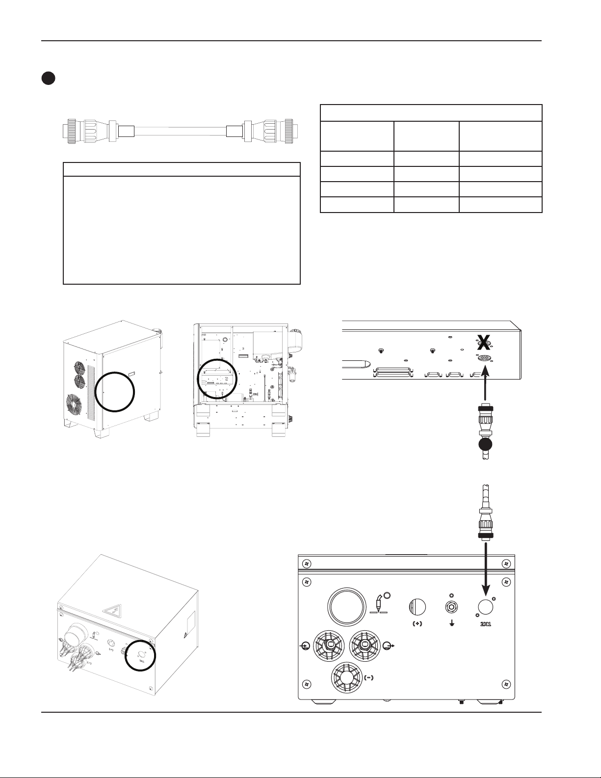
InstallatIon
3
3
Ignition console power cable
Cable signal list – power supply to ignition console
Power supply end Ignition console end
Pin No. Description Pin No.
1 120 Vac-hot 1
Part no. Length Part no. Length
123865* 2.1 m (7 ft) 123836 20 m (65 ft)
123419 3 m (10 ft) 123425 22.5 m (75 ft)
123834 4.5 m (15 ft) 123736 25 m (82 ft)
123420 6 m (20 ft) 123426 30 m (100 ft)
123670 7.5 m (25 ft) 123672 35 m (115 ft)
123422 9 m (30 ft) 123938 37.5 m (125 ft)
123835 10 m (35 ft) 123673 45 m (150 ft)
123423 12 m (40 ft) 123837 60 m (200 ft)
123671 15 m (50 ft) 123838 75 m (250 ft)
* Cable number 123865 is for use with systems that have the ignition console mounted on the power supply
2 120 Vac-return 2
3 Ground 3
4 Not used 4
3-18 HPR130XD Auto Gas – 806330
Page 57
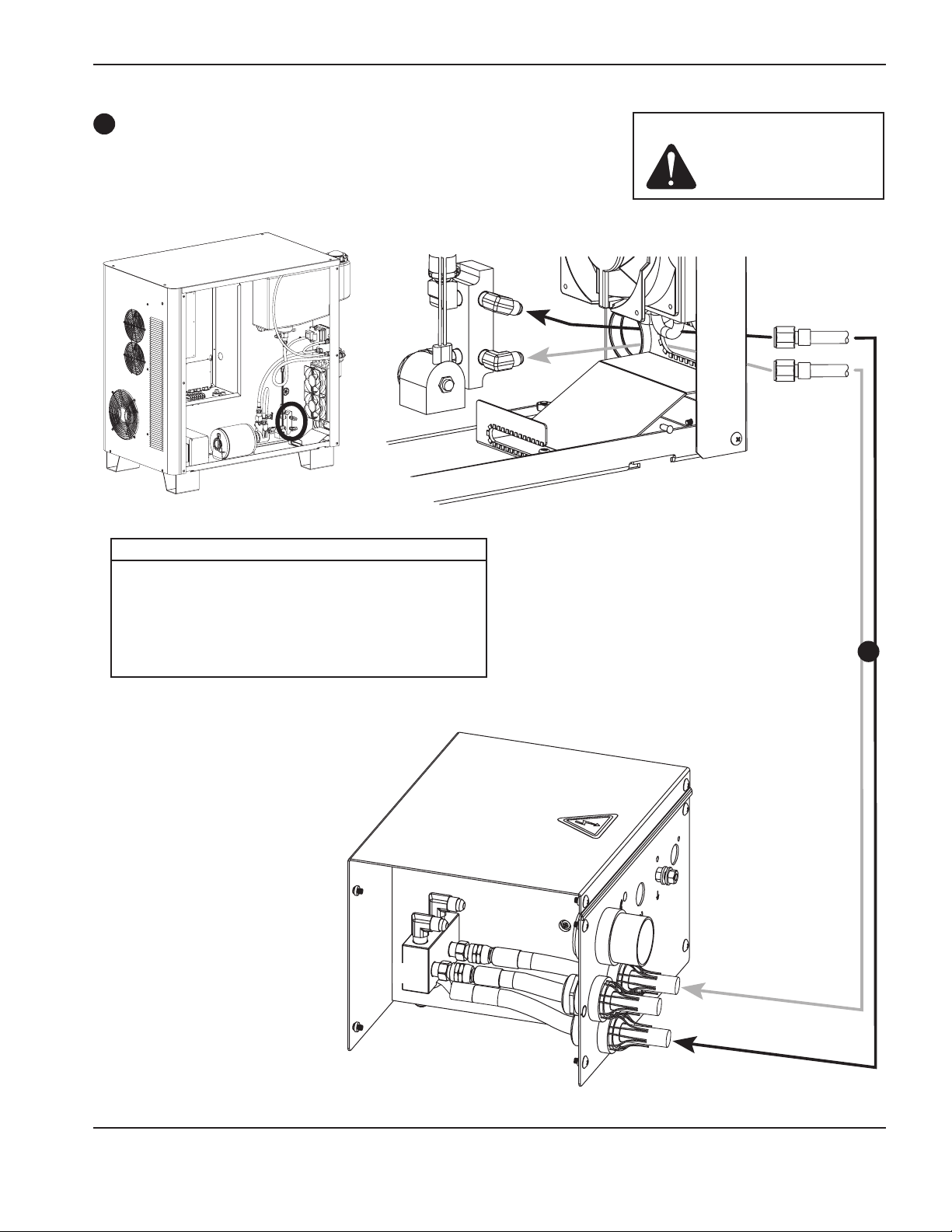
InstallatIon
4
4
Ignition console coolant hoses
Part no. Length Part no. Length
228030* 0.7 m (2.5 ft) 128984 20 m (65 ft)
028652 3 m (10 ft) 128078 25 m (85 ft)
028440 4.5 m (15 ft) 028896 35 m (115 ft)
028441 7.5 m (25 ft) 028445 45 m (150 ft)
128173 10 m (35 ft) 028637 60 m (200 ft)
028442 15 m (50 ft) 128985 75 m (250 ft)
Caution: Never use PTFE
tape on any joint
preparation.
Red
Green
Green
Red
* Hose set number 228030 is for use with systems that have the ignition console mounted on the power supply
HPR130XD Auto Gas – 806330 3-19
Page 58

InstallatIon
5
Power supply to selection console cables
Control cable
Part no. Length Part no. Length
123784* 3 m (10 ft) 123841 20 m (65 ft)
123839 4.5 m (15 ft) 123737 25 m (82 ft)
123963 6 m (20 ft) 123738 35 m (115 ft)
123691 7.5 m (25 ft) 123739 45 m (150 ft)
123840 10 m (35 ft) 123842 60 m (200 ft)
123711 15 m (50 ft) 123843 75 m (250 ft)
Cable signal list – power supply to gas console
Power supply end Gas console end
Pin No. Input/Output Description Pin No. Input/Output Function
1 Not used 1 Not used
6 Not used 6 Not used
2 Input/Output CAN L 2 Input/Output CAN serial communication
7 Input/Output CAN H 7 Input/Output CAN serial communication
3 CAN ground 3 CAN ground reference
9 Not used 9 Not used
8 Not used 8 Not used
4 Not used 4 Not used
5 Not used 5 Not used
Power cable
6
Cable signal list – power supply to gas console
Power supply end Gas console end
Pin No. Description Pin No.
Part no. Length Part no. Length
123785* 3 m (10 ft) 123848 20 m (65 ft)
123846 4.5 m (15 ft) 123740 25 m (82 ft)
123964 6 m (20 ft) 123676 35 m (115 ft)
123674 7.5 m (25 ft) 123677 45 m (150 ft)
123847 10 m (35 ft) 123849 60 m (200 ft)
123675 15 m (50 ft) 123850 75 m (250 ft)
1 120 Vac-hot 1
2 120 Vac-return 2
3 Ground 3
4 Not used 4
5 Not used 5
6 24 Vac-hot 6
7 24 Vac-return 7
* Cable numbers 123784 and 123785 are for use with systems that have the selection console mounted on the power supply
3-20 HPR130XD Auto Gas – 806330
Page 59

InstallatIon
5
6
1X1
J300
J103
Female
Male
6
3X3
3X1
3X2
3X4
5
HPR130XD Auto Gas – 806330 3-21
Page 60

InstallatIon
7
Selection console to metering console connections
Cable and gas hose assembly
Part no. Length
128992 3 m (10 ft)
128993 4.5 m (15 ft)
128952 7.5 m (25 ft)
128994 10 m (35 ft)
128930 15 m (50 ft)
128995 20 m (65 ft)
Power cable signal list – 9-pin connectors
Metering console end Selection console end
Pin No. Input/Output Description Pin No. Input/Output Function
1 Input 120 VAC power 1 Output AC in, return
2 Input 120 VAC power 2 Output AC in, hot
3 Input Chassis ground 3 Output Chassis ground
4 Not used 4 Not used
5 Not used 5 Not used
6 Not used 6 Not used
7 Not used 7 Not used
Female end to metering console Male end to selection console
Typical female DSUB connector
Comunication cable signal list – 9-pin DSUB connectors
Metering console end Selection console end
Pin No. Input/Output Description Pin No. Input/Output Function
2 Input/Output CAN L 2 Input/Output CAN communication
3 Input CAN ground 3 Output Power ground
7 Input/Output CAN H 7 Input/Output CAN communication
9 Input Not used 9 Output Not used
3-22 HPR130XD Auto Gas – 806330
Page 61

7
Caution: Never use PTFE
tape on any joint
preparation.
InstallatIon
HPR130XD Auto Gas – 806330 3-23
Page 62
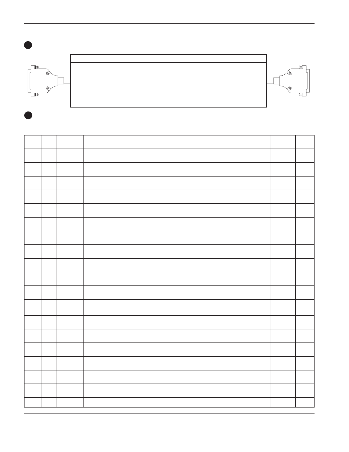
InstallatIon
8
Power supply to CNC interface cable
Part no. Length Part no. Length Part no. Length
123210 3 m (10 ft) 123216 13.5 m (45 ft) 123742 35 m (115 ft)
123211 4.5 m (15 ft) 123023 15 m (50 ft) 123219 37.5 m (125 ft)
To J 300
123212 6 m (20 ft) 123494 16.5 m (55 ft) 123220 45 m (150 ft)
123022 7.5 m (25 ft) 123851 20 m (65 ft) 123852 60 m (200 ft)
123213 9 m (30 ft) 123217 22.5 m (75 ft) 123853 75 m (250 ft)
123214 10 m (35 ft) 123741 25 m (82 ft)
123215 12 m (40 ft) 123218 30 m (100 ft)
Optional multi-system CNC interface cable
9
Power supply
end
Wire
color Pin #
Black
Red
Black
Green221
Black
Blue
Black
Yellow423
Black
Brown524
Black
Orange625
Red
White726
Red
Green827
Red
Blue
Red
Yellow1029
Red
Brown1130
Red
Orange1231
Green
White1332
Green
Blue
Green
Yellow1534
Green
Brown1635
Green
Orange1736
White
Black1837
20
22
28
14
33
19 CNC +24 VDC Not connected
Input/
Output Signal name Function
1
3
9
Input
Input
Output
Output
Output
Output
Output
Output
Output
Output
Output
Output
Output
Output
Output
Output
Output
Output
Input
Input
Input
Input
Input
Input
Input
Input
Rx –
Rx +
Tx –
Tx +
RS-422 ground
None
Motion 1 E (–)
Motion 1 C (+)
Error E (–)
Error C (+)
Rampdown error E (–)
Rampdown error C (+)
Not ready E (–)
Not ready C (+)
Motion 2 E (–)
Motion 2 C (+)
Motion 3 E (–)
Motion 3 C (+)
Motion 4 E (–)
Motion 4 C (+)
None
None
Corner (–)
Corner (+)
Pierce (–)
Pierce (+)
Hold (–)
Hold (+)
Start (–)
Start (+)
None
None
None
Power ground
Power ground
CNC +24 VDC
RS-422 serial receiver
RS-422 serial receiver
RS-422 serial transmitter
RS-422 serial transmitter
RS-422 serial ground
Not used
Notifies the CNC that an arc transfer has occurred and to begin
machine motion once the CNC’s pierce delay has timed out.
Notifies the CNC that an error has occurred
Notifies the CNC that a rampdown error has occurred
Notifies the CNC that the plasma system is not ready to fire an arc
Notifies the CNC that an arc transfer has occurred and to begin
machine motion once the CNC’s pierce delay has timed out
Notifies the CNC that an arc transfer has occurred and to begin
machine motion once the CNC’s pierce delay has timed out
Notifies the CNC that an arc transfer has occurred and to begin
machine motion once the CNC’s pierce delay has timed out
Not used
Not used
The CNC Notifies the plasma system that a corner is approaching
and to reduce cut current (Cut current is CNC selectable or
defaults to 50% of cut current)
The CNC Notifies the plasma system to maintain the shield preflow
until the CNC releases the signal
Not required without CommandTHC. CommandTHC requires
signal to preflow gases during IHS
The CNC initiates the plasma arc
Not used
Not used
Not used
Ground
Ground
Available 24 VDC (200 milliamps maximum) see notes
(see schematics for installation information)
CNC end
Input/
Output Notes
Output
Output
Input
Input
Input
Input
Input
Input
Input
Input
Input
Input
Input
Input
Input
Input
Output
Output
Output
Output
Output
Output
2 & 3
2
2
2
2 & 3
2 & 3
2 & 3
1
1
1
1
4
3-24 HPR130XD Auto Gas – 806330
Page 63

Notes to CNC interface cable run list
InstallatIon
Note 1. Inputs are optically isolated. They require 24 VDC at 7.3 mA, or dry-contact closure. The external relay’s life
may be improved by adding a metallized-polyester capacitor (0.022µF 100 V or higher) in parallel with the
relay contacts.
Note 2. Outputs are optically isolated, open collector, transistors. The maximum rating is 24 VDC at 10 mA.
Note 3. Machine motion is selectable and is used for configurations with multiple plasma systems.
Note 4.* CNC +24 VDC provides 24 VDC at 200 mA maximum. A jumper is required on J301 to use 24Vpower.
Caution: The CNC cable must be constructed using cable with 360 degree shielding and
metal housing connectors at each end. The shielding must be terminated to the
metal housings at each end to ensure proper grounding and to provide the best
shielding.
* See example 1 on page 3-27
HPR130XD Auto Gas – 806330 3-25
Page 64
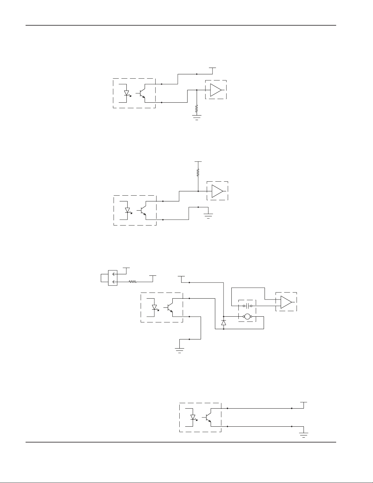
InstallatIon
Examples of output circuits
1. Logic interface, active-high
2. Logic interface, active-low
HPR
HPR
5 VDC-24 VDC
C
+
-
E
10K
(optional)
CNC/PLC
High-impedance (≤10 mA)
5 VDC-24 VDC
10K
(optional)
CNC/PLC
C
+
-
E
High-impedance (≤10 mA)
3. Relay interface
CNC +24 V
+24 VDC
Install a
Jumper
108056
J304
°t
HPR
4. Do not use this configuration. Warranty will be void.
CNC +24 V
C
+
-
E
Power
ground
HPR
CNC/PLC
High-current
contact closure
External relay
24 VDC low-power coil
≤10 mA or ≥2400 ohms
All relay coils require a freewheeling diode
across the relay coil
C
+
VOIDS
WARRANTY
inputs (AC or DC)
Any voltage
-
E
3-26 HPR130XD Auto Gas – 806330
Page 65
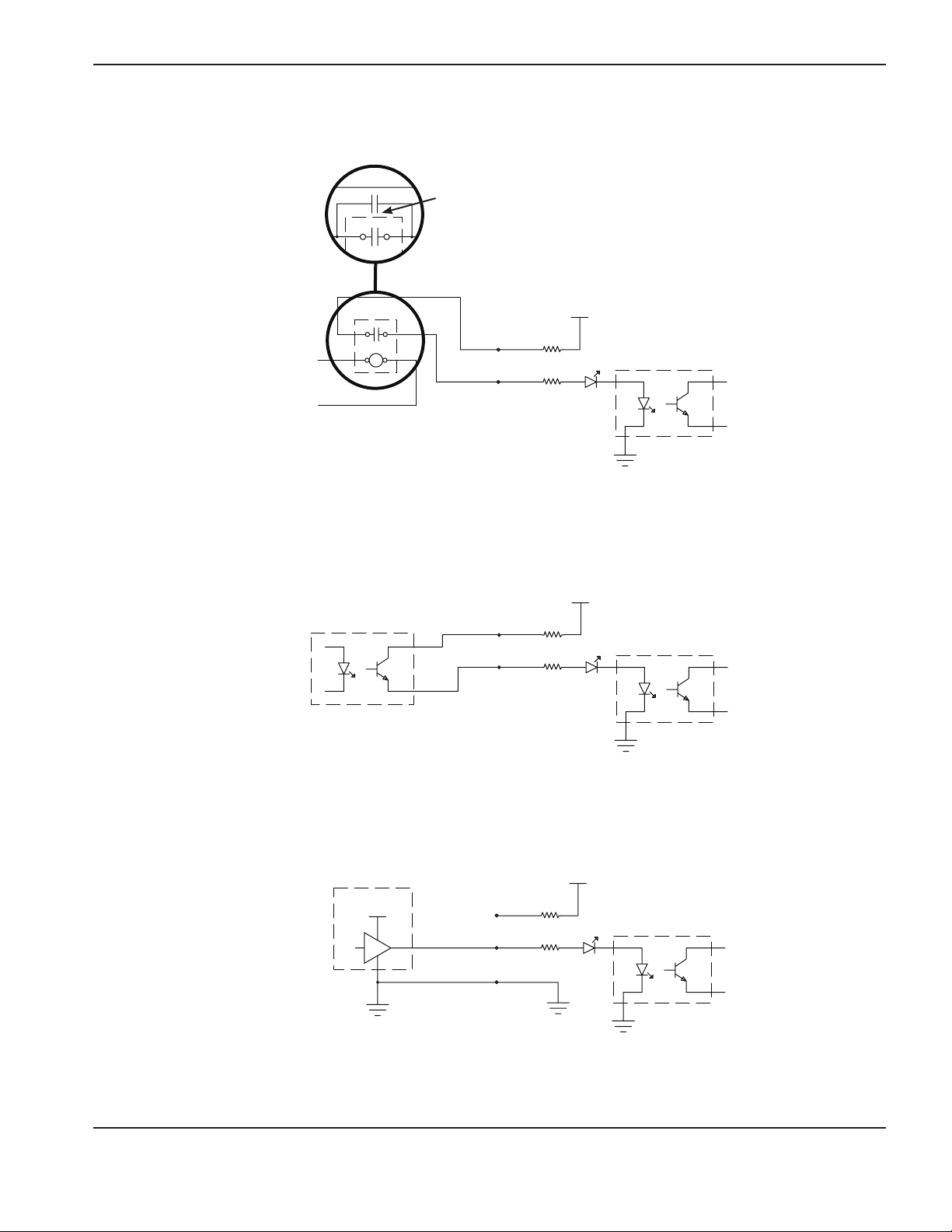
Examples of input circuits
1. Relay interface
InstallatIon
Note: The external relay’s life may be improved by adding a
metallized-polyester capacitor (0.022µF 100 V or higher)
inparallel with the relay contacts.
+24 VDC
Output from
CNC/PLC
2. Optocoupler interface
HPR
External relay
(AC or DC)
Power
ground
+24 VDC
CNC/PLC
HPR
Transistor-output
optocoupler
Power
ground
3. Amplified-output interface
CNC/PLC
12 V-24 VDC
Active-high drive
+24 VDC
HPR
Power
ground Power
ground
HPR130XD Auto Gas – 806330 3-27
Page 66
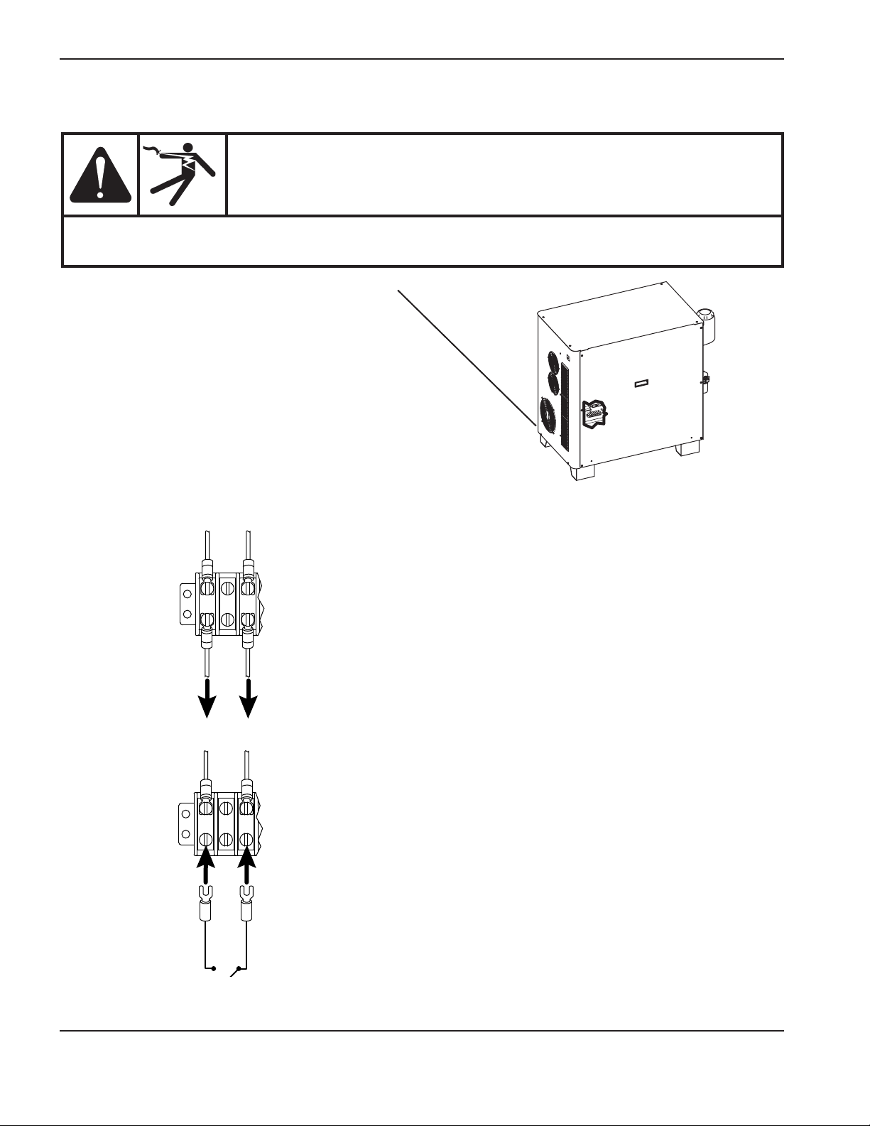
InstallatIon
Remote ON/OFF switch (provided by customer)
DANGER
ELECTRIC SHOCK CAN KILL
Disconnect electrical power before performing any maintenance.
See the Safety Section in this Manual for more safety precautions.
1. Locate terminal block 2 (TB2) in the power supply.
2. Remove wire 1 and wire 3 as shown. These wires do not need to be reconnected.
1
3
TB2
21 3
1
3
3. Connect switch to terminals 1 and 3 as shown.
3
1
TB2
21 3
TB2 location
Note: Use a switch, relay or solid-state relay that is compatible with 24 VAC @ 100 mA. It must be a maintained
contact switch, not a momentary contact switch.
3-28 HPR130XD Auto Gas – 806330
Page 67
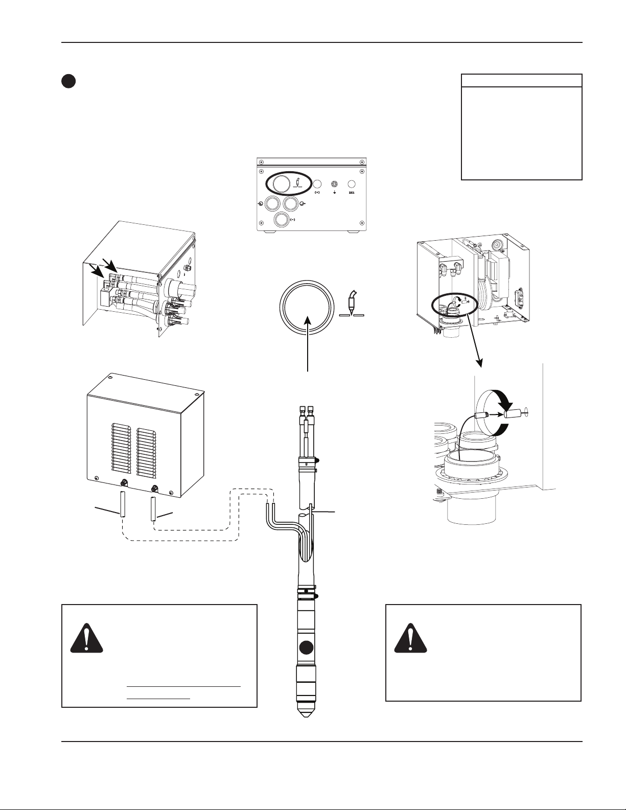
InstallatIon
10
Torch lead assembly
Part no. Length
228291 2 m (6 ft)
228292 3 m (10 ft)
228293 4.5 m (15 ft)
228294 6 m (20 ft)
228295 7.5 m (25 ft)
228296 10 m (35 ft)
228297 15 m (50 ft)
228547 20 m (65 ft)
Blue
Black
Caution: The length of the hoses
from the torch to the
metering console are
critical to cut quality
and consumable life.
Do not alter the length
of the hoses.
10
Plasma-gas vent hose
(white)
Caution: Locate the exposed end
of the plasma-gas vent
hose away from sparks
caused by piercing
to avoid ignition and
possible damage to the
torch leads.
HPR130XD Auto Gas – 806330 3-29
Page 68
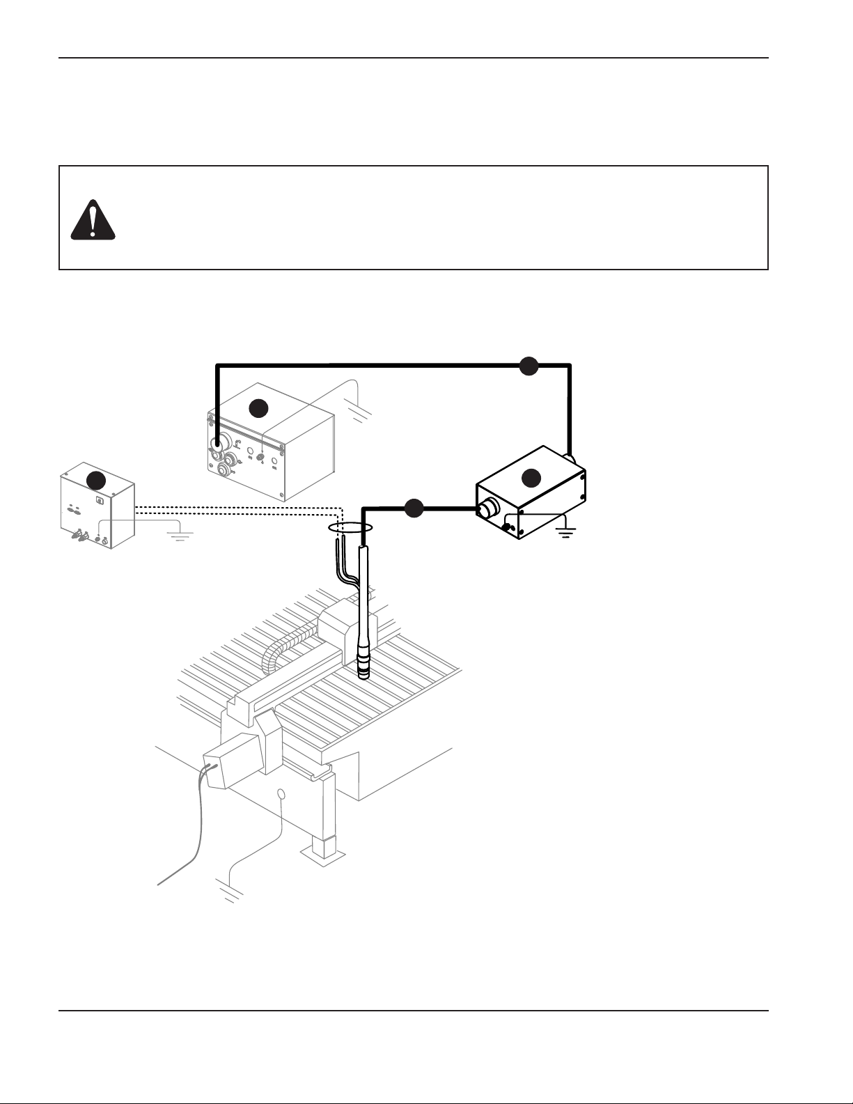
InstallatIon
Torch lead junction box (Optional)
Note: See the Parts list for part numbers
Caution: Total lead length from the ignition console to the torch must be less than or equal to:
20 m (65 feet) for HPR130XD / HPR260XD
15 m (50 feet) for HPR400XD / HPR800XD
1. Metering console
3
2
1
4
2. Ignition console
3. Junction box lead
4. Junction box
5. Junction box to
torch lead
5
3-30 HPR130XD Auto Gas – 806330
Page 69
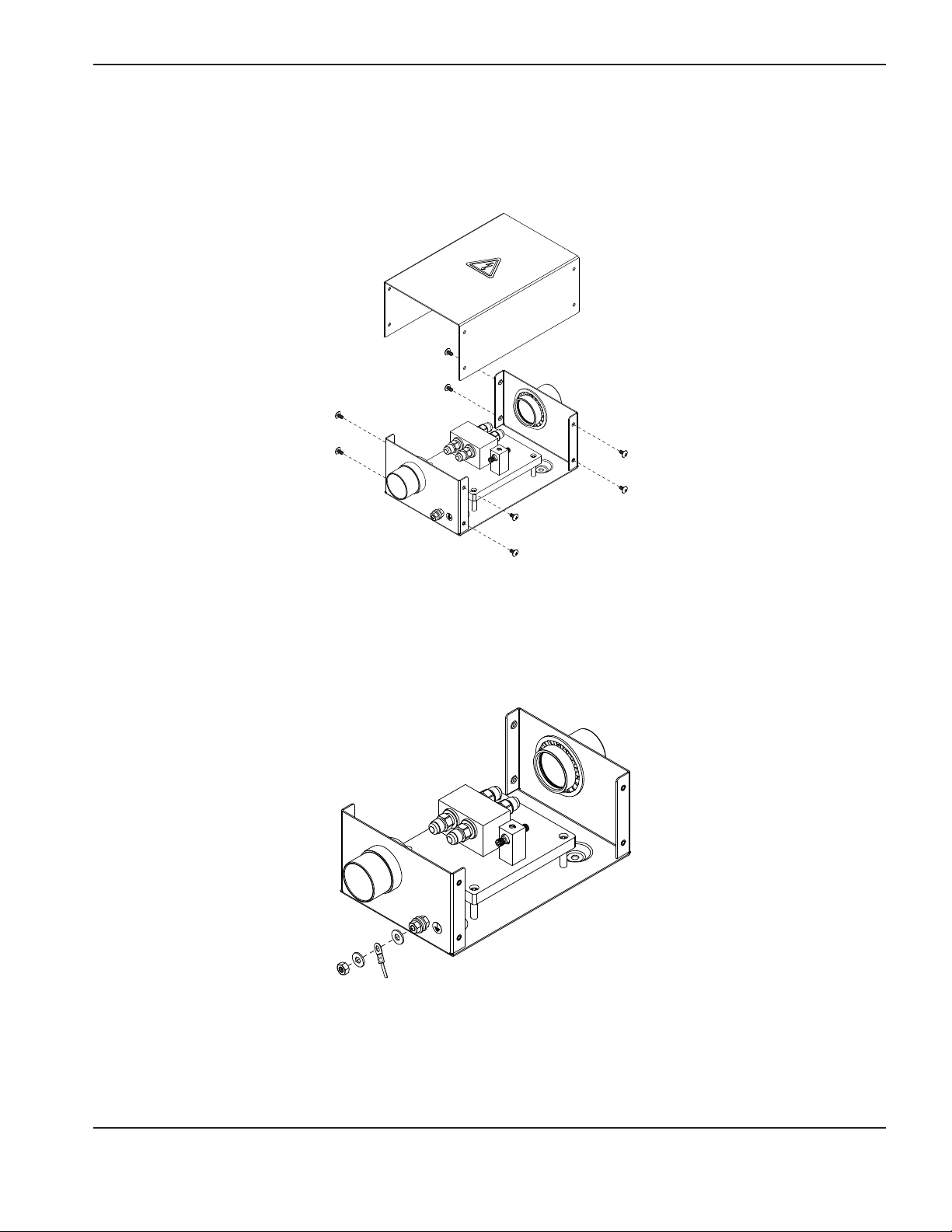
Install the junction box
1. Remove the cover fom the junction box
InstallatIon
2. Mount the junction box near the cutting location. (See Specification – for Junction box mounting dimensions)
Note: Allow space to install and remove the cover of the box for servicing.
3. Ground the junction box to the bus bar on the cutting table or equivalent. See Recommended grounding and
shielding in the Installation section in your system’s instruction manual for more information.
HPR130XD Auto Gas – 806330 3-31
Page 70
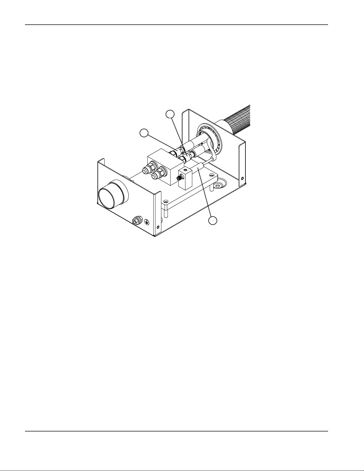
InstallatIon
1
3
Connect the leads
Note: Do not overtighten the connections
Junction box to the ignition console
1. Connect one end of the junction box lead to the junction box.
Note: The lead can go in either end of the junction box.
2
From the ignition console
1 Coolant supply hose (green) 3 Pilot arc lead (yellow)
2 Coolant return hose (red)
3-32 HPR130XD Auto Gas – 806330
Page 71
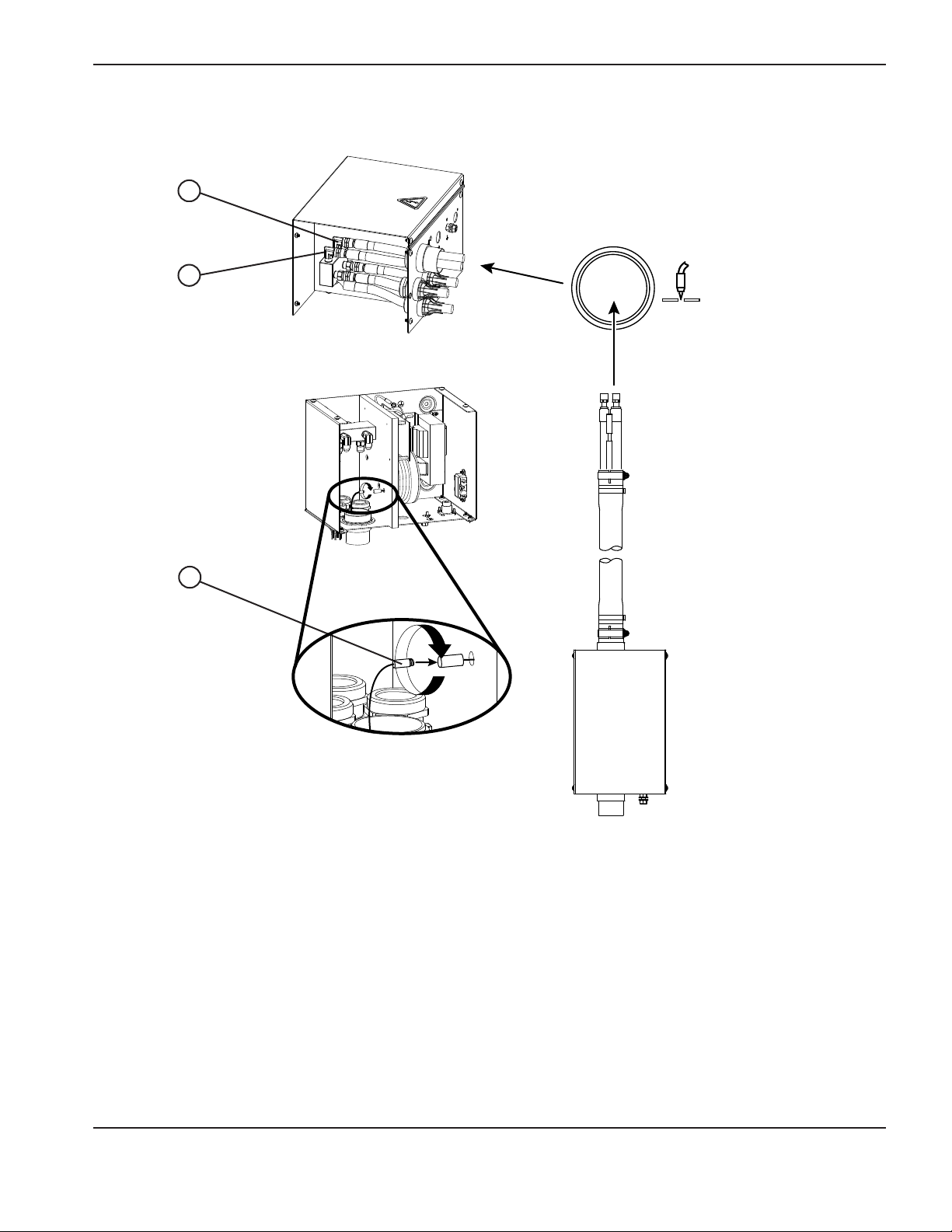
2. Connect the other end of the junction box lead to the ignition console.
1
2
3
InstallatIon
1 Coolant supply hose (green) 3 Pilot arc lead (yellow)
2 Coolant return hose (red)
HPR130XD Auto Gas – 806330 3-33
Page 72
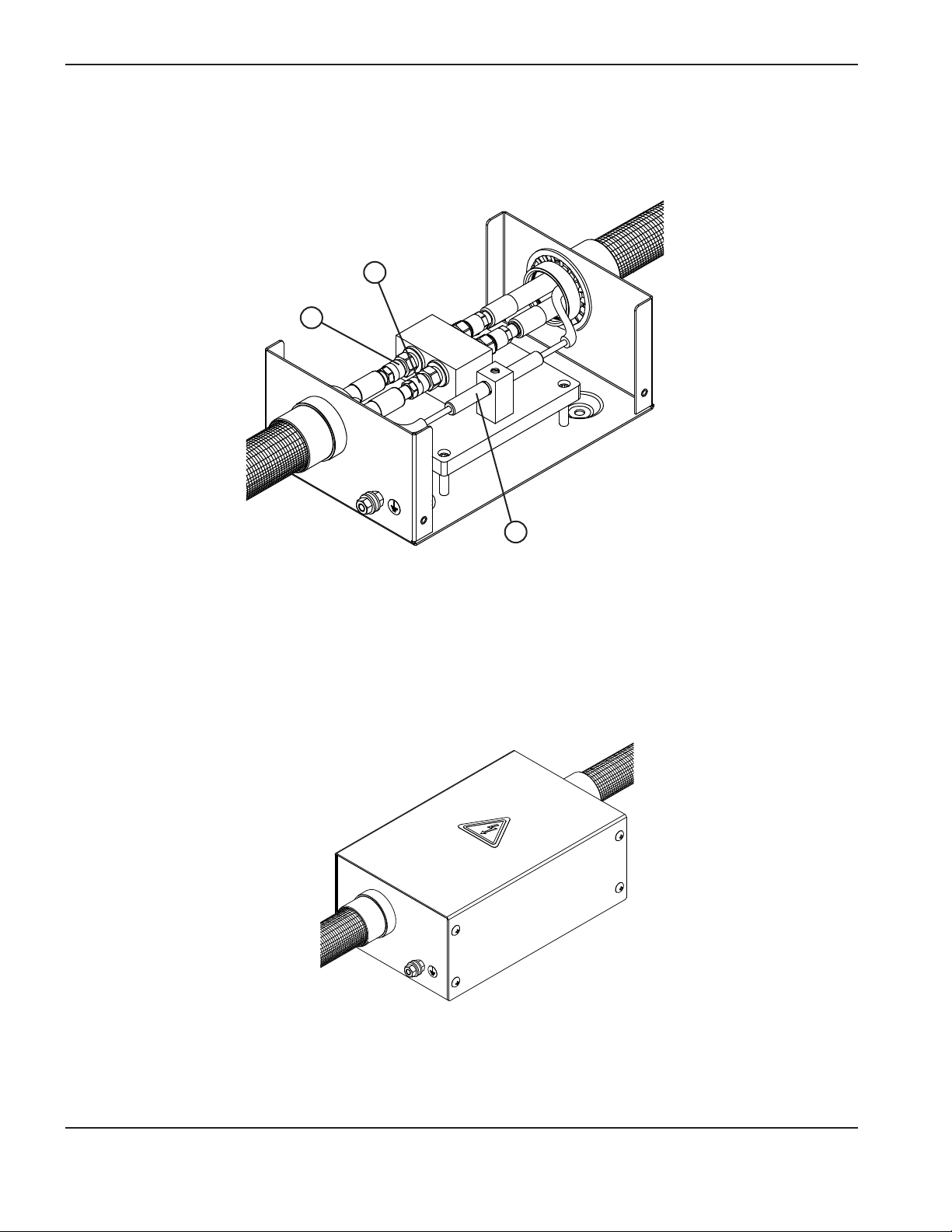
InstallatIon
3
Lead from the torch to the junction box
1. Connect the lead from the torch to the junction box.
1
2
From the torch
From the ignition console
1 Coolant supply hose (green) 3 Pilot arc lead (yellow)
2 Coolant return hose (red)
2. Install the junction box cover.
3-34 HPR130XD Auto Gas – 806330
Page 73
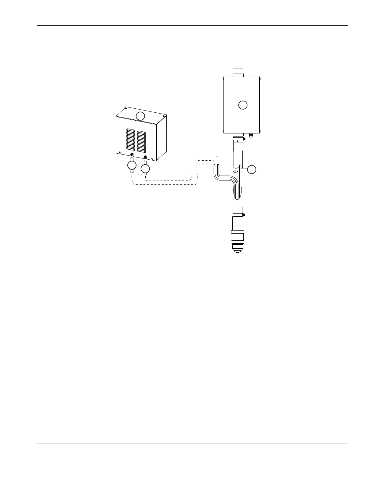
3. Connect the torch hoses to the metering console.
3
2
4
1
5
InstallatIon
1 Metering console
2 Junction box
3 Plasma gas vent hose (white)
4 Plasma gas hose (black)
5 Shield hose (blue)
HPR130XD Auto Gas – 806330 3-35
Page 74
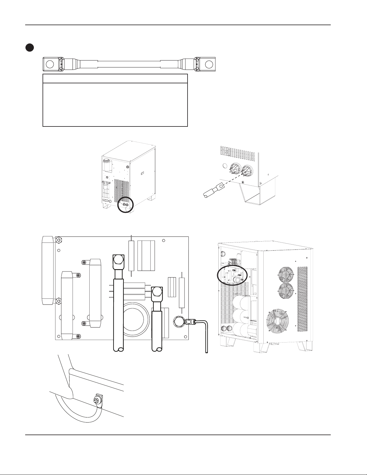
InstallatIon
11
Work lead
Work table
Part no. Length Part no. Length
123661 3 m (10 ft) 123734 25 m (82 ft)
123813 4.5 m (15 ft) 123664 35 m (115 ft)
123662 7.5 m (25 ft) 123665 45 m (150 ft)
123814 10 m (35 ft) 123778 60 m (200 ft)
123663 15 m (50 ft) 123779 75 m (250 ft)
123815 20 m (65 ft)
Power supply
Work lead
Work lead
Lower frame of work table (typical).
3-36 HPR130XD Auto Gas – 806330
Page 75

InstallatIon
E
Torch connections
Connect the torch to the torch lead assembly
1. Uncoil the first 2 meters (6.5 ft) of the leads on a flat surface.
2. Hold the torch assembly in place with the spanner wrench (104269) and remove the mounting sleeve from the torch
assembly.
3. Push back the braided cover and slide the sleeve over the leads. Align the torch with the hoses in the lead assembly.
The hoses must not be twisted. They are taped together to help prevent twisting.
Sleeve
Braided cover
4. Connect the coolant return hose (red).
Coolant return hose
Caution: Never use PTFE
tape on any joint
preparation.
HPR130XD Auto Gas – 806330 3-37
Page 76

InstallatIon
5. Connect the pilot arc lead (yellow). Insert the connector into the torch receptacle and turn it by hand until it is tight.
6. Connect the optional ohmic contact wire.
6a. Route the ohmic contact wire through the opening in the braided cover and the torch sleeve.
Sleeve
Braided cover
6b. Insert the connector into the torch receptacle and turn it by hand until it is tight.
Ohmic contact wire part numbers (Not part of the HPR130XD system. Shown for reference only.)
Part no. Length
123983 3 m (10 ft)
123984 6 m (20 ft)
123985 7.5 m (25 ft)
123986 9 m (30 ft)
123987 12 m (40 ft)
123988 15 m (50 ft)
123989 23 m (75 ft)
123990 30 m (100 ft)
123991 45 m (150 ft)
3-38 HPR130XD Auto Gas – 806330
Page 77

InstallatIon
7. Connect the plasma-gas vent hose (white).
8. Connect the coolant supply hose (green).
Note: The connectors in steps
7–10 are push-to-connect
fittings.
To make a connection, push
the hose fitting into the
appropriate connector until it
stops, 13 mm (0.5 in.).
connector-collar
To disconnect a fitting, push
the connector-collar toward
the torch, and pull the hose
away from the torch.
9. Connect the plasma gas hose (black).
10. Connect the shield gas hose (blue).
HPR130XD Auto Gas – 806330 3-39
Page 78

InstallatIon
11. Slide the torch sleeve over the connections and screw it onto the torch assembly.
12. Slide the braided cover up to the torch sleeve. Make sure that the plasma, shield and vent hoses are routed through
the hole in the braided cover. Loosen the hose clamp on the braided cover, slide the braided cover and clamp over
the sleeve and tighten the clamp.
3-40 HPR130XD Auto Gas – 806330
Page 79

Connect the torch to the quick-disconnect
Apply a thin film of silicone
lubricant to each o-ring
InstallatIon
Torch body
220706
Torch quick-disconnect receptacle
220705
Installation note
Align the torch body to the torch leads and secure
byscrewing completely together. Be certain that there
isnospace between the torch body and the o-ring on
the torch leads. See also Torch connections earlier in this
sectionfor torch lead connections to ignition console.
HPR130XD Auto Gas – 806330 3-41
Page 80
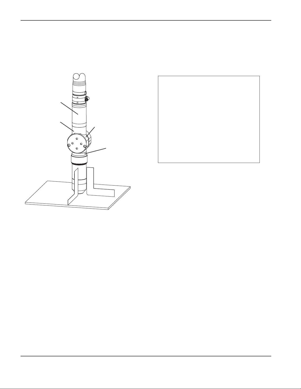
InstallatIon
Torch mounting and alignment
Mounting the torch
Upper torch sleeve
Lower torch sleeve
Torch mounting
bracket
(customer supplied)
Installation
1. Install the torch (with torch leads
attached) in the torch mounting bracket.
2. Position the torch below the mounting
bracket, so that the bracket is around the
lower portion of the torch sleeve but not
touching the torch quick-disconnect.
3. Tighten the securing screws.
Quick-disconnect
receptacle
Note: The bracket should be as low on the
torch sleeve as possible to minimize
vibration at the tip of the torch.
Torch alignment
To align the torch at right angles to the workpiece, use a square. See figure above.
3-42 HPR130XD Auto Gas – 806330
Page 81
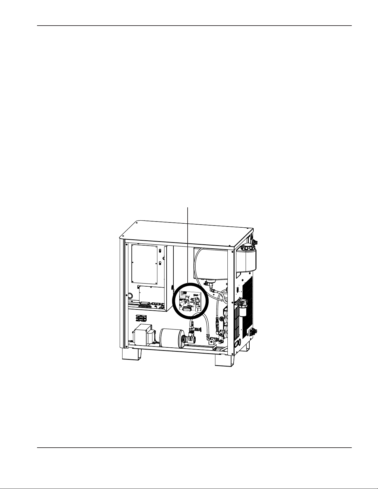
InstallatIon
Torch lifter requirement
The system requires a high-quality, motorized torch lifter with sufficient travel to cover all cutting thickness requirements.
The lifter must provide 203 mm (8 in.) of vertical travel. The unit should have the capability of maintaining a constant
speed of up to 5080 mm/min (200 ipm) with positive braking. A unit which drifts through the stop point is not
acceptable.
Hypernet
Hypernet is only used to connect certain Hypertherm components to each other. An HPRXD system can be connected
to the ArcGlide® torch height control, and an EDGE® Pro or MicroEDGE® Pro CNC using an ethernet hub and cable.
The Hypernet PCB provides communication between components and is the source for the arc voltage needed for the
torch height control. See the ArcGlide instruction manual (806450), the EDGE Pro instruction manual (806360) or the
MicroEDGE Pro CNC instruction manual (807290) for more information.
Location of the Hypernet PCB
HPR130XD Auto Gas – 806330 3-43
Page 82

InstallatIon
Power requirements
General
All switches, slow-blow fuses and power cables are customer-supplied and must be chosen as outlined by applicable
national and local electrical codes. Installation must be performed by a licensed electrician. Use a separate, primary, line
disconnect switch for the power supply. Recommendations on fuse and circuit breaker sizing are listed below, however
actual sizes required will vary based on individual site electrical line conditions (including but not limited to source
impedance, line impedance, and line voltage fluctuation), product inrush characteristics, and regulatory requirements.
The main feed protection device (Circuit Breaker or Fuse) must be sized to handle all branch-feed loads for both inrush
and steady-state current. The power supply must be wired into one of the branch-feed circuits. The power supply has
asteady-state current listed in the table below.
Use a motor-start circuit breaker or equivalent if time delay high inrush fuses are not permitted by local and national
codes. Time delay fuses and circuit breakers must be capable of withstanding inrush current that is up to 30 times the
rated input current (FLA) for 0.01 seconds and up to 12 times the rated input current (FLA) for 0.1 seconds.
Recommended
Rated
input current (FLA)
Input voltage Phase
200/208 VAC 3 62/60 A 85 A 26.7 mm2 (3 AWG)
220 VAC 3 57 A 85 A 26.7 mm2 (3 AWG)
240 VAC 3 52 A 65 A 21.2 mm2 (4 AWG)
380 VAC 3 33 A 40 A 8.3 mm2 (8 AWG)
400 VAC 3 32 A 40 A 8.3 mm2 (8 AWG)
415 VAC 3 32 A 40 A 8.3 mm2 (8 AWG)
440 VAC 3 28 A 35 A 8.3 mm2 (8 AWG)
480 VAC 3 26 A 35 A 8.3 mm2 (8 AWG)
600 VAC 3 21 A 30 A 5.3 mm2 (10 AWG)
Note: Cable AWG recommendations taken from table 310-16 of the National Electric Codehandbook (USA).
@ 19.5 kW output
time delay,
high inrush
fuse size
Recommended Cable
size for 15 m (50 feet)
maximum length
Rated for 60° C (140° F)
3-44 HPR130XD Auto Gas – 806330
Page 83

Line disconnect switch
The line disconnect switch serves as the supply-voltage disconnecting (isolating) device. Install
this switch near the power supply for easy access by the operator.
Installation must be performed by a licensed electrician and according to applicable national
and local codes.
The switch should:
• Isolate the electrical equipment and disconnect all live conductors from the supply
voltage when in the “OFF” position
• Haveone“OFF”andone“ON”positionclearlymarkedwith“O”(OFF)and“l”(ON)
• Have an external operating handle capable of being locked in the “OFF” position
• Containapower-operatedmechanismthatservesasanemergencystop
• Haveslow-blowfusesinstalledfortheproperbreakingcapacity(seetableabove).
InstallatIon
SWITCH BOX
16
Main power cable
Wire sizes vary based on the distance of the receptacle from the main box. The wire sizes listed in the table above were
taken from the National Electric Code 1990 handbook, table 310.16 (USA). Use a 4-conductor Type SO input power
cable with a conductor temperature rating of 60°C (140°F). Installation must be performed by a licensed electrician.
HPR130XD Auto Gas – 806330 3-45
Page 84
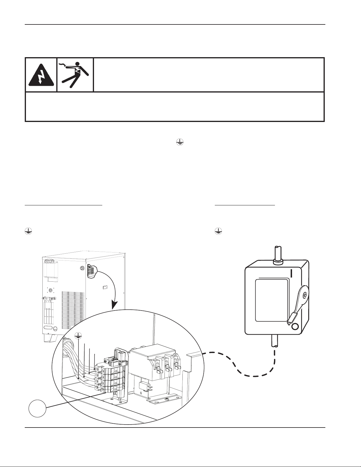
InstallatIon
Connect the power
DANGER
ELECTRIC SHOCK CAN KILL
The line disconnect switch must be in the OFF position before making the power cable
connections. In the U.S., use a “lock-out/tag-out” procedure until installation is complete. In other
countries, follow appropriate national and local safety procedures.
1. Insert the power cable through the strain relief at the rear of the power supply.
2. Connect the ground lead (PE) to the GROUND terminal ( ) of TB1 as shown below.
3. Connect the power leads to the terminals of TB1 as shown below.
4. Verify that the line disconnect switch is in the OFF position and remains in the OFF position for the
remainder of the installation of the system.
5. Connect the power cord leads to the line disconnect switch following national and local electrical codes.
North American wire colors
U = Black
V = White
W = Red
(PE) Earth ground = Green/Yellow
(PE)
W
V
U
European wire colors
U = Black
V = Blue
W = Brown
(PE) Earth ground = Green/Yellow
Line
disconnect
switch
Power
cable
TB1
3-46 HPR130XD Auto Gas – 806330
Page 85
InstallatIon
Torch coolant requirements
Torch coolant requirements
The system is shipped without any coolant in the tank. Before fi lling the coolant system, determine what coolant mix is
Premixed coolant for standard operating temperatures
correct for your operating conditions.
Observe the warning and cautions below. Refer to the Material Safety Data Sheets appendix for data on safety,
handling,and storage of propylene glycol and benzotriazole.
Propylene glycol and benzotriazole are irritating to skin and eyes, and harmful or fatal if
swallowed. Upon contact, flush skin or eyes with water. If swallowed, seek immediate medical
attention.
Never use automotive anti-freeze in place of propylene glycol. Antifreeze contains corrosion
inhibitors that will damage the torch coolant system.
Always use purified water in the coolant mixture in order to prevent damage to the pump and
corrosion in the torch coolant system.
DANGER
COOLANT CAN BE IRRITATING TO SKIN AND EYES AND
HARMFUL OR FATAL IF SWALLOWED
CAUTION
Defi nitions
Ambient temperature – The temperature of the room in which the chiller is being used.
Premixed coolant for standard operating temperatures
Use Hypertherm premixed coolant (028872) when operating in an ambient temperature range of -12°C to 40°C
(10°Fto104°F). Refer to the custom coolant mix recommendations, if temperatures during operation are ever outside
of this range.
Hypertherm premixed coolant consists of 69.8% water, 30% propylene glycol, and 0.2% benzotriazole.
10/16/08
HPR130XD Auto Gas – 806330 3-47
Page 86
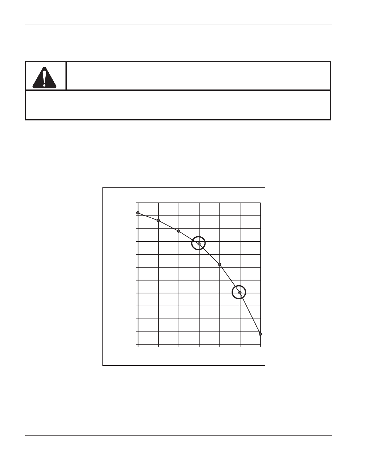
InstallatIon
10/16/08
Custom Coolant mix for cold operating temperatures (below-12°C/10°F)
100% glycol solution can also be mixed with purifi ed water (see next page for water purity requirements) to achieve the
06
Custom Coolant mix for cold operating temperatures
CAUTION
For operating temperatures colder than the temperature stated above, the percentage of
propylene glycol must be increased. Failure to do so could result in a cracked torch head, hoses,
or other damage to the torch coolant system due to freezing.
Use the chart below to determine what percentage of propylene glycol to use in the mixture.
Mix 100% glycol (028873) with the premixed Hypertherm coolant (028872) to increase the percentage of glycol. The
required protection from freezing.
Note: The maximum percentage of glycol should never exceed 50%.
-12
-18
-23
-29
Temperature
-34
-40
-46
-51
-57
°F°C
40
4
30
-1
20
-7
10
0
0
-1
0
-2
0
-3
0
-4
0
-5
0
-6
0
-7
0102030405
0
% of Propylene Glycol
Freezing Point of Propylene Glycol Solution
3-48 HPR130XD Auto Gas – 806330
Page 87

InstallatIon
Custom Coolant mix for hot operating temperatures (above 38° C / 100° F)
below 0°C
Water that does not meet the maximum purity specifications below can also cause problems. Deionized water that is too
Custom Coolant mix for hot operating temperatures
Treated water (with no propylene glycol) can only be used as coolant when ambient temperatures are never
Water purity requirements
(32° F). For operations in very warm temperatures, treated water will provide the best cooling properties.
Treated water refers to a mixture of purifi ed water, that meets the specifi cations below, and 1 part benzotriazole (BZT)
to 300 parts of water. BZT (128020) acts as a corrosion inhibitor for the copper based coolant system contained in the
plasma system.
Water purity requirements
It is critical to maintain a low level of calcium carbonate in the coolant to avoid reduced performance of the torch or
cooling system.
Always use water that meets the minimum and maximum specifications in the table below when using a custom coolant
mix.
Water that does not meet the minimum purity specifications below can cause excessive deposits on the nozzle that will
alter the water flow and produce an unstable arc.
pure will cause leaching problems with the coolant system plumbing.
Use water purified by any method (deionization, reverse osmosis, sand filters, water softeners, etc.) as long as the water
purity meets the specifications in the table below. Contact a water specialist for advice in choosing a water filtration
system.
Water purity measurement method
Conductivity
μS/cm
Water purity
Pure water (for reference only) 0.055 18.3 0 0
Maximum purity 0.5 2 0.206 0.010
Minimum purity 18 0.054 8.5 0.43
Maximum potable water
(forreference only)
10/16/08
at25°C(77° F)
1000 0.001 495 25
Resistivity
mΩ-cm
at25°C(77° F)
Dissolved solids
(ppm of NaCl)
Grains per gallon
(gpg of CaCO
)
2
HPR130XD Auto Gas – 806330 3-49
Page 88
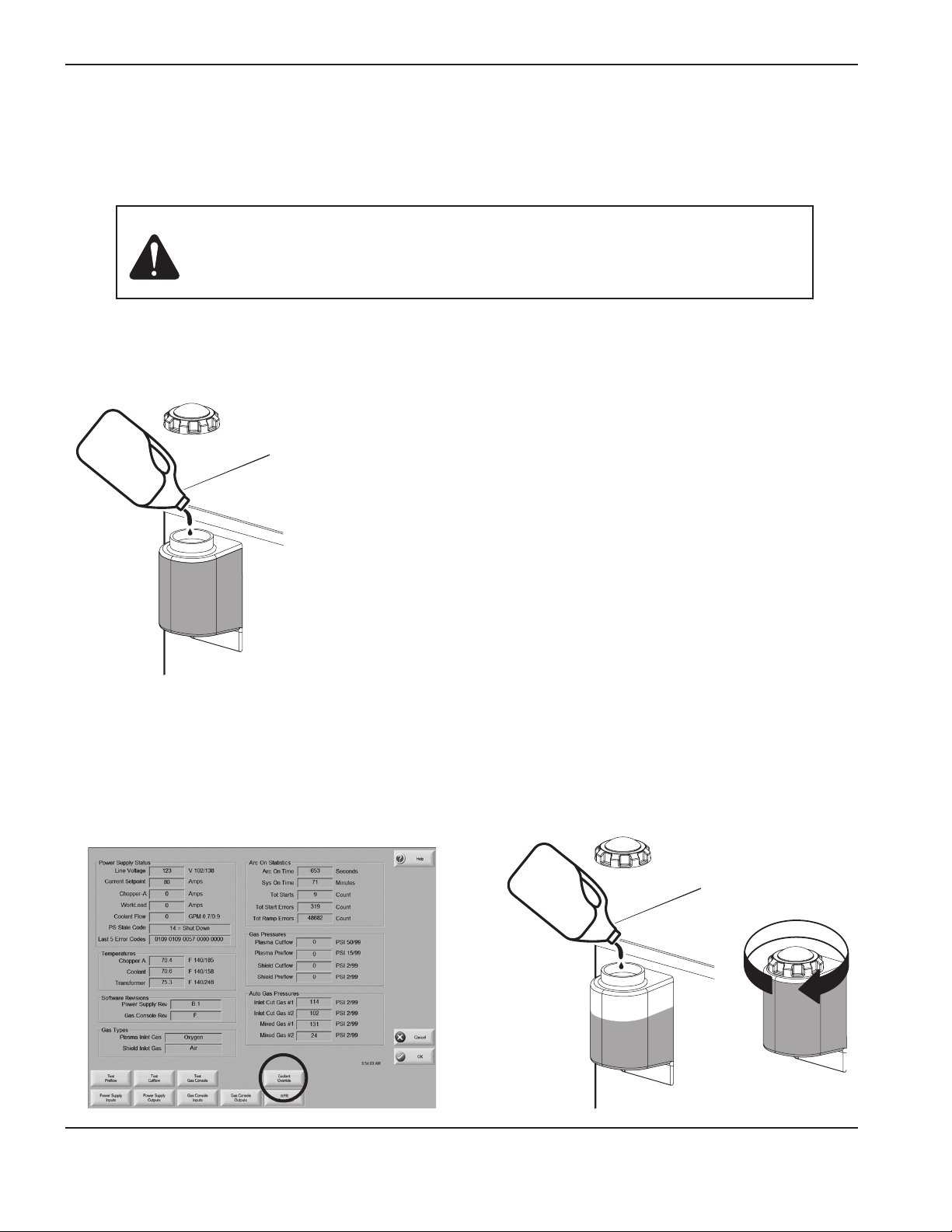
InstallatIon
Fill the power supply with coolant
The system will take 11.4 – 15.1 liters (3 to 4 gallons) of coolant depending on the length of the torch leads and
whether the system has a local or remote ignition console.
Caution: Using the wrong coolant can cause damage to the system. Refer to torch
coolant requirements in this section for more information.
Do not over fill the coolant tank.
1. Add coolant to the power supply until the
tank is full.
3. Locate the CNC screen for manual pump
control. The pump needs to run to fill the leads.
2. Turn ON the power supply using the remote
ON/OFF switch or the CNC.
4. Add coolant to the power supply until
the tank is full and replace the filler cap.
3-50 HPR130XD Auto Gas – 806330
Page 89
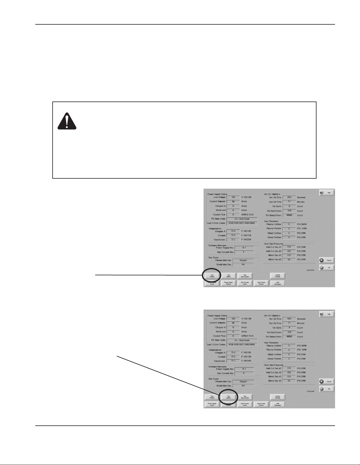
InstallatIon
Gas requirements
The customer must furnish all gases and gas-supply regulators for the system. Use a high-quality, 2-stage pressure
regulator located within 3 m (10 ft) of the selection console. See Gas regulators in this section for recommendations.
See the Specification section for gas and flow specifications. See Supply gas hoses at the end of this section for
recommendations.
Caution: Gas supply pressures not within the specifications in Section 2 can cause
poor cut quality, poor consumable life and operational problems.
If the purity level of the gas is too low or if there are leaks in the supply
hoses or connections,
• Cut speeds can decrease
• Cut quality can deteriorate
• Cutting thickness capability can decrease
• Parts life can shorten
Setting the supply regulators
1. Turn OFF the power to the system. Set all gas
regulator pressures to 8 bar (115 psi).
2. Turn ON the power to the system using the remote
ON/OFF switch or the CNC.
3. Set to Test Preflow.
4. While gas is flowing adjust the supply regulator for the
shield gas pressure to 8 bar (115 psi).
5. Turn OFF Test Preflow.
6. Set system to Test Cutflow.
7. While gas is flowing adjust the supply regulator for the
plasma gas to 8 bar (115 psi).
8. Turn OFF Test Cutflow.
HPR130XD Auto Gas – 806330 3-51
Page 90

InstallatIon
Gas regulators
Low-quality gas regulators do not provide consistent supply pressures and can result in poor cut quality and system
operation problems. Use a high-quality, 1-stage, gas regulator to maintain consistent gas supply pressure, if using liquid
cryogenic or bulk storage. Use a high-quality, 2-stage, gas regulator to maintain consistent gas supply pressure from
high pressure gas cylinders.
The high-quality gas regulators listed below are available from Hypertherm and meet U.S. Compressed Gas Association
(CGA) specifications. In other countries, select gas regulators that conform to national and local codes.
2-stage regulator
Part
Number Description Qty.
Single stage regulator
128544 Kit: Oxygen, 2-stage * 1
128545 Kit: Inert Gas, 2-stage 1
128546 Kit: Hydrogen (H5, H35 and methane) 2-stage 1
128547 Kit: Air, 2-stage 1
128548 Kit: 1-stage (for use with cryogenic liquid nitrogen or oxygen) 1
022037 Oxygen, 2-stage 1
022038 Inert gas, 2-stage 1
022039 Hydrogen/methane, 2-stage 3
022040 Air, 2-stage 1
022041 Line regulator, 1-stage 1
* Kits include appropriate fittings
3-52 HPR130XD Auto Gas – 806330
Page 91
InstallatIon
Supply gas plumbing
Rigid copper plumbing or suitable flexible hose may be used for all gas supplies. Do not use steel or aluminum pipe.
After installation, pressurize the entire system and check for leaks.
Recommended hose diameters are 9.5 mm (3/8 in.) for lengths < 23 m (75 ft) and 12.5 mm (1/2 in.) for
lengths > 23 m (75 ft).
For flexible-hose systems, use a hose designed for inert gas to carry air, nitrogen or argon-hydrogen. See the last page
of this section for hose part numbers.
Caution: Never use PTFE tape on any joint preparation.
Caution: When connecting the selection console to the supply gases, make sure that
allhoses, hose connections and fittings are acceptable for use with oxygen
and argon-hydrogen. Installation must be made in accordance with national
and local codes.
Note: When cutting with oxygen as the plasma gas, air must also be connected to theselection console to
achieve the proper mixtures in the preflow and cutflowmodes.
WARNING
CUTTING WITH OXYGEN CAN CAUSE FIRE OR EXPLOSION
Cutting with oxygen as the plasma gas can cause a potential fire hazard due to the oxygen-enriched
atmosphere that it creates. As a precaution, Hypertherm recommends that an exhaust ventilation
system be installed when cutting with oxygen.
Flashback arrestors are required (unless not available for specific gases or required pressures)
toprevent fire from propagating back to supply gas.
HPR130XD Auto Gas – 806330 3-53
Page 92

InstallatIon
Connect the supply gases
Connect the supply gases to the selection console. Torch leads must be purged between gas changes.
Caution: Synthetic lubricants containing esters that are used in some air compressors
will damage polycarbonates used in the air regulator bowl.
Fitting Size
N2 / Ar 5/8 – 18, RH, internal (inert gas) “B”
Air 9/16 – 18, JIC, #6
H35 / F5 / H5 9/16 – 18, LH, (fuel gas) “B”
O
2
9/16 – 18, RH, (oxygen) “B”
Caution: Replacing the fittings on the selection console may cause the internal valves
to malfunction, because particulates can migrate into the valves.
3-54 HPR130XD Auto Gas – 806330
Page 93

Supply gas hoses
12
Oxygen hose
Part no. Length Part no. Length
024607 3 m (10 ft) 024738 25 m (82 ft)
024204 4.5 m (15 ft) 024450 35 m (115 ft)
024205 7.5 m (25 ft) 024159 45 m (150 ft)
024760 10 m (35 ft) 024333 60 m (200 ft)
024155 15 m (50 ft) 024762 75 m (250 ft)
024761 20 m (65 ft)
13
Nitrogen or argon hose
Part no. Length Part no. Length
024210 3 m (10 ft) 024739 25 m (82 ft)
024203 4.5 m (15 ft) 024451 35 m (115 ft)
024134 7.5 m (25 ft) 024120 45 m (150 ft)
024211 10 m (35 ft) 024124 60 m (200 ft)
024112 15 m (50 ft) 024764 75 m (250 ft)
024763 20 m (65 ft)
InstallatIon
Caution: Never use PTFE
tape on any joint
preparation.
14
Air hose
Part no. Length Part no. Length
024671 3 m (10 ft) 024740 25 m (82 ft)
024658 4.5 m (15 ft) 024744 35 m (115 ft)
024659 7.5 m (25 ft) 024678 45 m (150 ft)
024765 10 m (35 ft) 024680 60 m (200 ft)
024660 15 m (50 ft) 024767 75 m (250 ft)
024766 20 m (65 ft)
15
Argon-hydrogen (H35) or nitrogen-hydrogen (F5)
Part no. Length Part no. Length
024768 3 m (10 ft) 024741 25 m (82 ft)
024655 4.5 m (15 ft) 024742 35 m (115 ft)
024384 7.5 m (25 ft) 024743 45 m (150 ft)
024769 10 m (35 ft) 024771 60 m (200 ft)
024656 15 m (50 ft) 024772 75 m (250 ft)
024770 20 m (65 ft)
HPR130XD Auto Gas – 806330 3-55
Page 94

InstallatIon
3-56 HPR130XD Auto Gas – 806330
Page 95

Section 4
OPERATION
In this section:
Daily start-up ...............................................................................................................................................................................................4-3
Check torch ......................................................................................................................................................................................4-3
Power indicators ........................................................................................................................................................................................4-4
General ..............................................................................................................................................................................................4-4
Power supply ....................................................................................................................................................................................4-4
Selection console ............................................................................................................................................................................4-4
Metering console .............................................................................................................................................................................4-4
CNC controller requirements ..................................................................................................................................................................4-5
Base required elements .................................................................................................................................................................4-5
Required real time elements .........................................................................................................................................................4-5
Required diagnostic elements ......................................................................................................................................................4-5
CNC screen examples ..............................................................................................................................................................................4-6
Main (control) screen ......................................................................................................................................................................4-6
Diagnostics screen .........................................................................................................................................................................4-7
Test screen .......................................................................................................................................................................................4-8
Cut chart screen ..............................................................................................................................................................................4-9
Consumable selection ........................................................................................................................................................................... 4-10
Standard cutting (0°) ................................................................................................................................................................... 4-10
Bevel cutting (0° to 45°) ............................................................................................................................................................. 4-10
Marking ...........................................................................................................................................................................................4-10
Consumables for mirror-image cutting ....................................................................................................................................4-10
SilverPlus electrodes ................................................................................................................................................................... 4-10
Mild steel ........................................................................................................................................................................................ 4-11
Stainless steel ............................................................................................................................................................................... 4-11
Aluminum ........................................................................................................................................................................................ 4-12
Mild steel bevel cutting ...............................................................................................................................................................4-13
Stainless steel bevel cutting ...................................................................................................................................................... 4-13
Install and Inspect consumables ......................................................................................................................................................... 4-14
Install consumables ......................................................................................................................................................................4-14
Inspect consumables ...................................................................................................................................................................4-15
Torch maintenance ................................................................................................................................................................................. 4-17
Routine maintenance ................................................................................................................................................................... 4-17
Quick-disconnect maintenance ................................................................................................................................................ 4-17
HPR130XD Auto Gas – 806330 Revision 2 4-1
Page 96

OperatiOn
Maintenance kit ............................................................................................................................................................................. 4-17
Torch connections .................................................................................................................................................................................. 4-18
Replace torch water tube ......................................................................................................................................................................4-18
Common cutting faults ..........................................................................................................................................................................4-19
How to optimize cut quality ..................................................................................................................................................................4-20
Tips for table and torch ............................................................................................................................................................... 4-20
Plasma set-up tips........................................................................................................................................................................4-20
Maximize the life of consumable parts ..................................................................................................................................... 4-20
Additional factors of cut quality ................................................................................................................................................. 4-21
Additional improvements ............................................................................................................................................................4-23
Cut charts ................................................................................................................................................................................................. 4-24
Overview .........................................................................................................................................................................................4-24
Bevel cutting definitions ........................................................................................................................................................................ 4-27
Estimated kerf-width compensation ................................................................................................................................................... 4-30
4-2 HPR130XD Auto Gas – 806330 Revision 2
Page 97
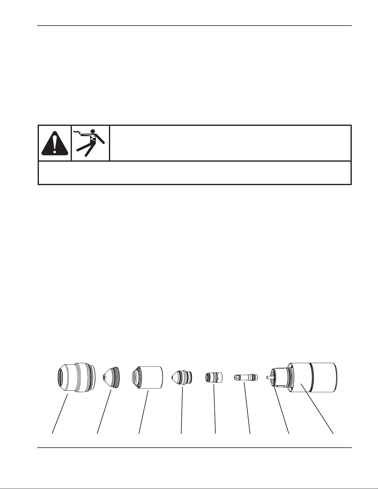
OperatiOn
Daily start-up
Prior to start-up, ensure that your cutting environment and that your clothing meet the safety requirements outlined in the
Safety section of this manual.
Check torch
DANGER
ELECTRIC SHOCK CAN KILL
Before operating this system, you must read the Safety section thoroughly. Turn OFF the power
supply’s main disconnect switch before proceeding with the following steps.
1. Turn main disconnect switch to the power supply OFF.
2. Remove the consumables from the torch and check for worn or damaged parts. Always place the consumables
on a clean, dry, oil-free surface after removing. Dirty consumables can cause the torch tomalfunction.
• RefertoInstall and inspect consumables later in this section for details and for parts inspection tables.
• RefertotheCut charts to choose the correct consumables for your cutting needs.
3. Replace consumable parts. Refer to Install and inspect consumables later in this section for details.
4. Ensure that the torch is perpendicular to the workpiece.
Shield cap TorchCurrent ringElectrodeSwirl ringNozzleShield Nozzle retaining cap
HPR130XD Auto Gas – 806330 Revision 2 4-3
Page 98
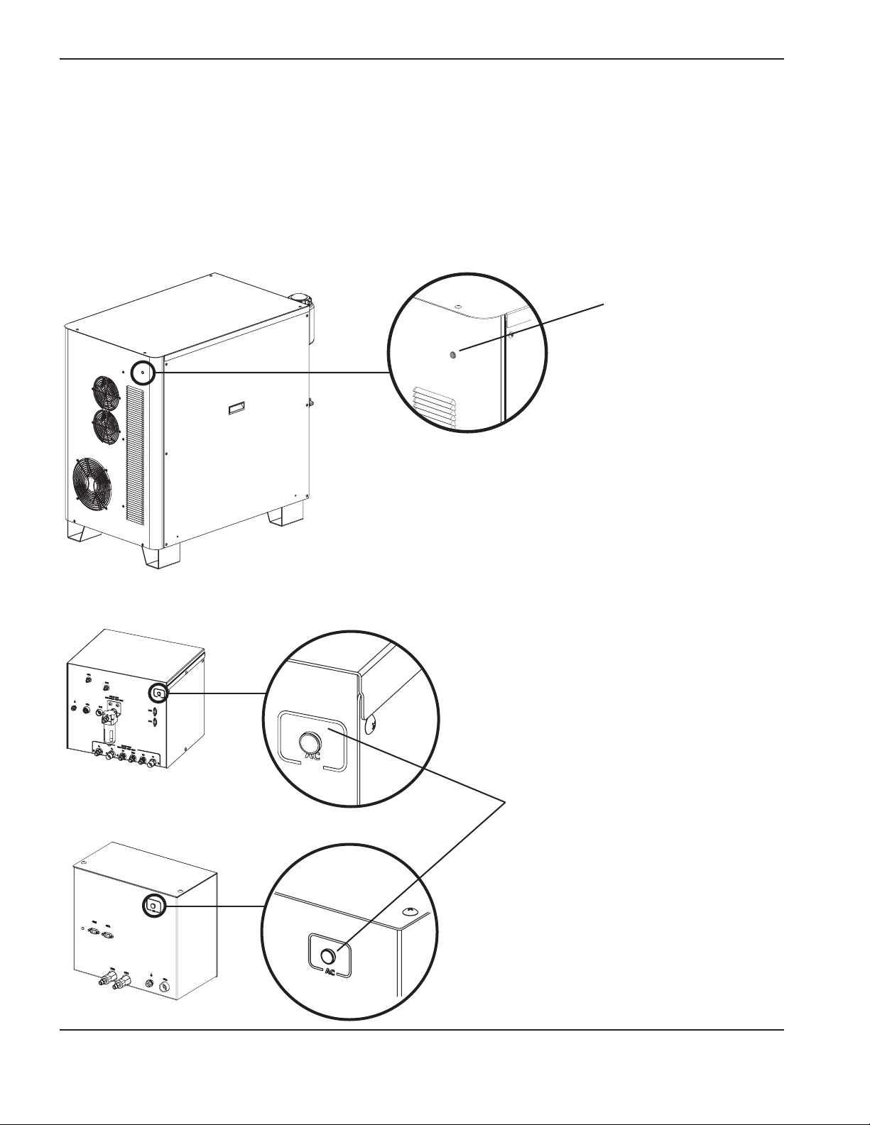
OperatiOn
Power indicators
General
Power for the system is controlled by the CNC. The power supply, selection console and metering console each have
an LED lamp that illuminates when power is supplied to the component.
Power supply
Green indicator
Selection console
Metering console
Green indicator
4-4 HPR130XD Auto Gas – 806330 Revision 2
Page 99

OperatiOn
CNC controller requirements
Base required elements
The following elements should be able to be displayed and adjusted on the CNC for setup and basic system
information. The plasma system needs this group for basic setup and operation capability.
1. Remote ON/OFF
2. Ability to display and adjust the basic plasma process set-points (command ID #95)
a. Current setpoint
b. Plasma preflow
c. Plasma cutflow
d. Shield preflow
e. Shield cutflow
f. Plasma gas type
g. Shield gas type
h. Gas mixing set-points
3. Display basic system information
a. System error code
b. Gas and PS firmware version
4. Manual pump control
Required real time elements
The following elements should be able to be displayed in real time while cutting. This is necessary for trouble shooting
and diagnostic purposes.
5. Display line voltage
6. Display chopper current
7. Display work lead current
8. Display system status code
9. Display chopper temperature
10. Display transformer temperature
11. Display coolant temperature
12. Display coolant flow
13. Display pressure transducers
Required diagnostic elements
These elements provide additional diagnostic capability to the system for troubleshooting gas-delivery problems. The
CNC should be capable of executing these commands and displaying the relevant information for the respective test
according to the serial protocol guidelines.
14. Test preflow gases
15. Test cutflow gases
16. Inlet leak test
17. System leak test
18. System flow test
HPR130XD Auto Gas – 806330 Revision 2 4-5
Page 100
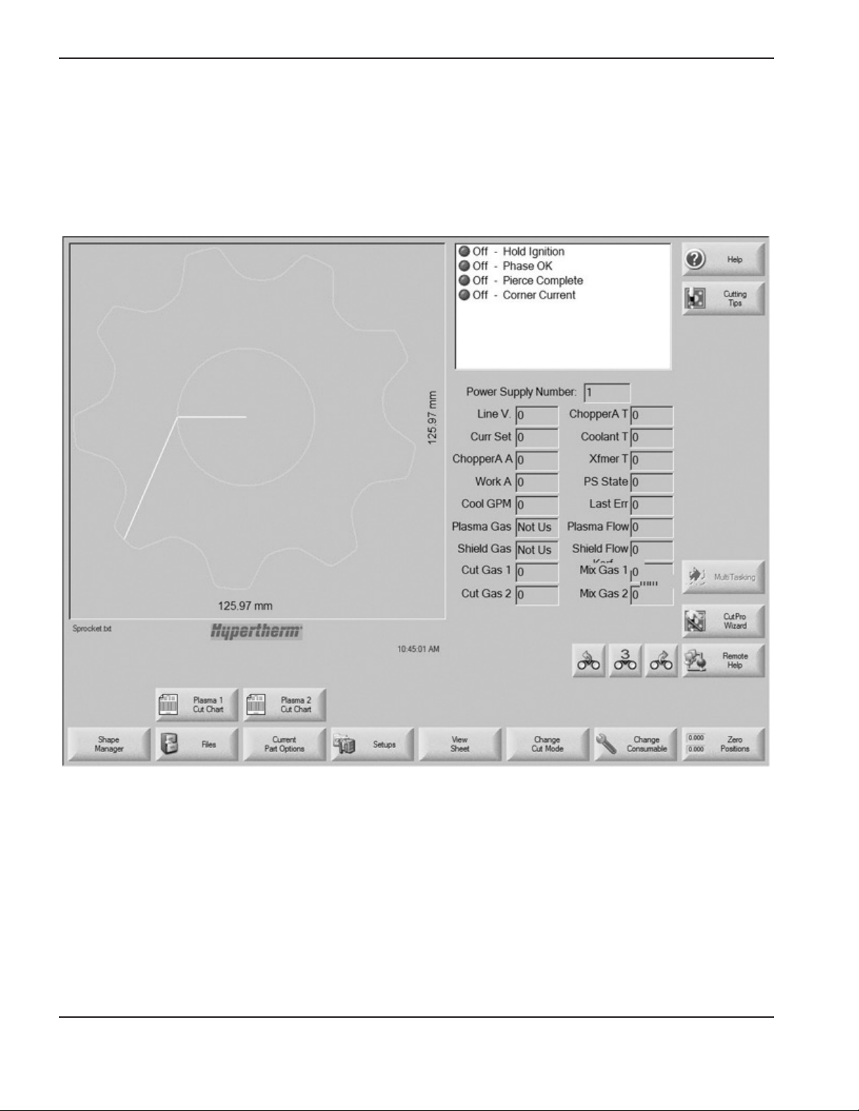
OperatiOn
CNC screen examples
The screens shown are for reference. The screens you work with may be different, but should include the functions
listed on the previous page.
Main (control) screen
4-6 HPR130XD Auto Gas – 806330 Revision 2
 Loading...