

Page 1

HyIntensity Fiber Laser
HyIntensity Fiber Laser
HFL010
HFL010
HFL015
HFL015
HFL020
HFL020
Instruction Manual
807090 – Revision 3
HFL030
HFL030
TM
TM
TM
TM
TM
TM
TM
TM
TM
TM
Page 2

Register your new Hypertherm system
Register your product online at www.hypertherm.com/registration for easier technical
and warranty support. You can also receive updates on new Hypertherm products and a
free gift as a token of our appreciation.
For your records
Serial number: ______________________________________________________
Purchase date: ______________________________________________________
Distributor: ______________________________________________________
___________________________________________________________________
___________________________________________________________________
Maintenance notes:
________________________________________________________________________
________________________________________________________________________
________________________________________________________________________
________________________________________________________________________
________________________________________________________________________
________________________________________________________________________
Page 3

HyIntensity Fiber Laser
HFL010, HFL015, HFL020, and HFL030
Instruction Manual
(P/N 807090)
Revision 3 – November, 2012
Hypertherm, Inc.
Hanover, NH USA
www.hypertherm.com
© 2012 Hypertherm, Inc.
All Rights Reserved
Hypertherm, HyIntensity Fiber Laser, HFL010, HFL015, HFL020 and HFL030 are trademarks of Hypertherm, Inc.
and may be registered in the United States and/or other countries.
Page 4

Hypertherm, Inc.
Etna Road, P.O. Box 5010
Hanover, NH 03755 USA
603-643-3441 Tel (Main Office)
603-643-5352 Fax (All Departments)
info@hypertherm.com (Main Office Email)
800-643-9878 Tel (Technical Service)
technical.service@hypertherm.com (Technical Service Email)
800-737-2978 Tel (Customer Service)
customer.service@hypertherm.com (Customer Service Email)
866-643-7711 Tel (Return Materials Authorization)
877-371-2876 Fax (Return Materials Authorization)
return.materials@hypertherm.com (RMA email)
Hypertherm Plasmatechnik GmbH
Technologiepark Hanau
Rodenbacher Chaussee 6
D-63457 Hanau-Wolfgang, Deutschland
49 6181 58 2100 Tel
49 6181 58 2134 Fax
49 6181 58 2123 (Technical Service)
Hypertherm (S) Pte Ltd.
82 Genting Lane
Media Centre
Annexe Block #A01-01
Singapore 349567, Republic of Singapore
65 6841 2489 Tel
65 6841 2490 Fax
65 6841 2489 (Technical Service)
Hypertherm (Shanghai) Trading Co., Ltd.
Unit 301, South Building
495 ShangZhong Road
Shanghai, 200231
PR China
86-21-60740003 Tel
86-21-60740393 Fax
Hypertherm Europe B.V.
Vaartveld 9
4704 SE
Roosendaal, Nederland
31 165 596907 Tel
31 165 596901 Fax
31 165 596908 Tel (Marketing)
31 165 596900 Tel (Technical Service)
00 800 4973 7843 Tel (Technical Service)
Hypertherm Japan Ltd.
Level 9, Edobori Center Building
2-1-1 Edobori, Nishi-ku
Osaka 550-0002 Japan
81 6 6225 1183 Tel
81 6 6225 1184 Fax
Hypertherm Brasil Ltda.
Rua Bras Cubas, 231 – Jardim Maia
Guarulhos, SP - Brasil
CEP 07115-030
55 11 2409 2636 Tel
55 11 2408 0462 Fax
Hypertherm México, S.A. de C.V.
Avenida Toluca No. 444, Anexo 1,
Colonia Olivar de los Padres
Delegación Álvaro Obregón
México, D.F. C.P. 01780
52 55 5681 8109 Tel
52 55 5683 2127 Fax
Hypertherm Korea Branch
#3904 Centum Leaders Mark B/D,
1514 Woo-dong, Haeundae-gu, Busan
Korea, 612-889
82 51 747 0358 Tel
82 51 701 0358 Fax
07/18/12
Page 5

table of contents
Safety ......................................................................................................................................................S-1
Introduction ................................................................................................................................................................................................ S-1
Operating instructions, guidelines, and rules ..................................................................................................................................... S-2
Protection of personnel ........................................................................................................................................................................... S-3
Laser safety officer ................................................................................................................................................................................... S-3
Condition of laser beam equipment ..................................................................................................................................................... S-3
Laser safety ................................................................................................................................................................................................ S-4
Laser safety warnings .............................................................................................................................................................................. S-5
Health concerns ........................................................................................................................................................................................ S-9
Laser safety eyewear (LSE) .................................................................................................................................................................... S-9
Acoustical noise ........................................................................................................................................................................................ S-9
Warning signs ............................................................................................................................................................................................ S-9
Gas, fumes and air quality....................................................................................................................................................................... S-9
Confined spaces ..................................................................................................................................................................................... S-10
Oxygen gas distribution for laser cutting ...........................................................................................................................................S-11
Public exhibitions and demonstrations ..............................................................................................................................................S-11
Large area viewing ..................................................................................................................................................................................S-11
Training ......................................................................................................................................................................................................S-12
Product stewardship ........................................................................................................................ PS-1
Introduction ............................................................................................................................................................................................. PS-1
National and local safety regulations ................................................................................................................................................. PS-1
Certification test marks ......................................................................................................................................................................... PS-1
Differences in national standards ....................................................................................................................................................... PS-1
Safe installation and use of shape cutting equipment .................................................................................................................. PS-1
Procedures for periodic inspection and testing .............................................................................................................................. PS-2
Qualification of test personnel .................................................................................................................................................. PS-2
Residual current devices (RCDs) ...................................................................................................................................................... PS-2
Higher-level systems ............................................................................................................................................................................. PS-3
Environmental stewardship ........................................................................................................... ES-1
Introduction ............................................................................................................................................................................................. ES-1
National and local environmental regulations .................................................................................................................................. ES-1
The RoHS directive ............................................................................................................................................................................... ES-1
Proper disposal of Hypertherm products ......................................................................................................................................... ES-1
The WEEE directive .............................................................................................................................................................................. ES-1
The REACH regulation ......................................................................................................................................................................... ES-1
Proper handling and safe use of chemicals ..................................................................................................................................... ES-2
Fumes emission and air quality ........................................................................................................................................................... ES-2
Electromagnetic Compatibility (EMC) ................................................................................... EMC-1
Introduction ......................................................................................................................................................................................... EMC-1
Installation and use ............................................................................................................................................................................ EMC-1
Assessment of area ........................................................................................................................................................................... EMC-1
Methods of reducing emissions ..................................................................................................................................................... EMC-1
Mains supply ............................................................................................................................................................................. EMC-1
HyIntensity Fiber Laser Instruction Manual – 807090 Revision 2 i
Page 6

table of contents
Maintenance of cutting equipment ................................................................................................................................................ EMC-2
Cutting cables .................................................................................................................................................................................... EMC-2
Equipotential bonding ....................................................................................................................................................................... EMC-2
Earthing of the workpiece ................................................................................................................................................................ EMC-2
Screening and shielding ................................................................................................................................................................... EMC-2
Warranty ................................................................................................................................................W-1
Attention .....................................................................................................................................................................................................W-1
General .......................................................................................................................................................................................................W-1
Patent indemnity .......................................................................................................................................................................................W-2
Limitation of liability .................................................................................................................................................................................W-2
National and local codes ........................................................................................................................................................................W-2
Liability cap ................................................................................................................................................................................................W-2
Insurance....................................................................................................................................................................................................W-2
Transfer of rights.......................................................................................................................................................................................W-2
Specifications ........................................................................................................................................1-1
Fiber laser supply .......................................................................................................................................................................................1-1
Overview ............................................................................................................................................................................................1-1
Requirements ...................................................................................................................................................................................1-2
Optical specifications .....................................................................................................................................................................1-3
Dimensions – HFL010, HFL015, and HFL020 ........................................................................................................................1-4
Dimensions – HFL030 ...................................................................................................................................................................1-5
LF150 laser head – 051025 .................................................................................................................................................................1-6
Overview ............................................................................................................................................................................................1-6
Mounting dimensions .....................................................................................................................................................................1-7
Collimator dimensions ....................................................................................................................................................................1-8
Collimator dimensions ....................................................................................................................................................................1-9
System gas requirements ..................................................................................................................................................................... 1-10
Gas quality and pressure requirements .................................................................................................................................. 1-10
Chiller requirements ............................................................................................................................................................................... 1-11
Coolant ...........................................................................................................................................................................................1-11
Flow rates ....................................................................................................................................................................................... 1-11
Cooling capacity ........................................................................................................................................................................... 1-11
Gas control console – 051024 .........................................................................................................................................................1-12
Overview .........................................................................................................................................................................................1-12
Beam delivery optical cable (BDO) .................................................................................................................................................... 1-13
Laser head controller – 051026 ........................................................................................................................................................1-14
Overview .........................................................................................................................................................................................1-14
CNC Requirements ................................................................................................................................................................................ 1-15
Hypertherm CNC ......................................................................................................................................................................... 1-15
Generic CNC ................................................................................................................................................................................ 1-16
Installation ..............................................................................................................................................2-1
Upon receipt ...............................................................................................................................................................................................2-1
Claims ...........................................................................................................................................................................................................2-1
Installation requirements ..........................................................................................................................................................................2-2
ii HyIntensity Fiber Laser Instruction Manual – 807090 Revision 2
Page 7

table of contents
Noise levels .................................................................................................................................................................................................2-2
Placement of system components .........................................................................................................................................................2-2
Site preparation before startup ...............................................................................................................................................................2-3
Installation requirements ..........................................................................................................................................................................2-4
System components .......................................................................................................................................................................2-5
Cables and hoses ...........................................................................................................................................................................2-5
Power cables (customer-supplied) .............................................................................................................................................2-5
Supply gas hoses (customer supplied) ......................................................................................................................................2-5
Recommended grounding and shielding practices ...........................................................................................................................2-6
Introduction .................................................................................................................................................................................................2-6
Types of grounding ..........................................................................................................................................................................2-6
Steps to take ....................................................................................................................................................................................2-7
Placement of the fiber laser supply .....................................................................................................................................................2-11
Lifting the fiber laser supply ....................................................................................................................................................... 2-12
Fiber laser supply preparation ..............................................................................................................................................................2-13
General information ......................................................................................................................................................................2-13
Emergency stop (E-Stop) switch installation .........................................................................................................................2-14
Electrical diagram for external safety switches ......................................................................................................................2-15
Stack Light installation ................................................................................................................................................................ 2-16
Dehumidifier drain installation .................................................................................................................................................... 2-17
Mounting the laser head controller (LHC) ........................................................................................................................................ 2-19
Mounting the gas console.....................................................................................................................................................................2-20
Chiller considerations ............................................................................................................................................................................ 2-21
Mounting the laser head ........................................................................................................................................................................ 2-22
Install the laser head mounting bracket ...................................................................................................................................2-22
Laser head grounding .................................................................................................................................................................2-23
Laser head mounting dimensions ............................................................................................................................................. 2-23
Beam delivery optical cable connection ............................................................................................................................................ 2-25
General Precautions .................................................................................................................................................................... 2-26
Unpacking Instructions ................................................................................................................................................................ 2-26
Beam delivery optical cable installation .................................................................................................................................. 2-27
Collimator installation .............................................................................................................................................................................2-28
General precautions ....................................................................................................................................................................2-28
Collimator proximity sensor ........................................................................................................................................................ 2-33
Laser head connectors .......................................................................................................................................................................... 2-35
Coolant hose connections .................................................................................................................................................................... 2-36
Fiber laser supply to laser head ................................................................................................................................................ 2-37
Beam delivery optical cable and collimator coolant hoses ................................................................................................. 2-38
Fiber laser supply to chiller .........................................................................................................................................................2-40
Cable connections..................................................................................................................................................................................2-41
Hypernet cable: fiber laser supply to a Hypertherm CNC – 223171 ..............................................................................2-41
Hypernet cable: fiber laser supply to laser head controller – 223171 ............................................................................2-42
Gas console control cable – 223138 ..................................................................................................................................... 2-43
Laser head I/O cable – 223169 ............................................................................................................................................2-44
Gas hoses ................................................................................................................................................................................................2-45
Gas control console to laser head ........................................................................................................................................... 2-45
HyIntensity Fiber Laser Instruction Manual – 807090 Revision 2 iii
Page 8

table of contents
Laser head controller power cable – (customer supplied) ......................................................................................................... 2-46
Line disconnect switch ................................................................................................................................................................2-47
Main power cables (fiber laser supply and chiller) .......................................................................................................................... 2-47
Connect the power ................................................................................................................................................................................. 2-48
Gas requirements ...................................................................................................................................................................................2-49
Gas regulators ......................................................................................................................................................................................... 2-50
Supply gas plumbing .............................................................................................................................................................................2-51
Connect the supply gases .........................................................................................................................................................2-52
Initial setup ..................................................................................................................................................................................... 2-53
CNC setups ............................................................................................................................................................................................. 2-54
Hypertherm CNC setup ..............................................................................................................................................................2-54
Lens assembly installation ....................................................................................................................................................................2-58
General precautions ....................................................................................................................................................................2-58
Set-up and Operation ..........................................................................................................................3-1
Safe operation ............................................................................................................................................................................................3-2
Sequence of operation with a Hypertherm CNC ....................................................................................................................3-3
Sequence of operation with a generic CNC ............................................................................................................................3-4
Marking and cutting mild steel with a generic CNC ...............................................................................................................3-5
H2O valve ..........................................................................................................................................................................................3-6
Flow meters ......................................................................................................................................................................................3-6
Fiber-to-fiber coupling unit ............................................................................................................................................................3-6
Laser power supply operation diagrams ..............................................................................................................................................3-7
Power ON sequence ......................................................................................................................................................................3-7
Laser power supply – faulted state ...........................................................................................................................................3-8
Laser power supply – laser beam OFF state .........................................................................................................................3-9
Laser power supply – laser beam ON state ........................................................................................................................ 3-10
Operating the laser head controller .................................................................................................................................................... 3-11
Navigating the Display Screen .................................................................................................................................................. 3-12
Changing the value of a parameter: ......................................................................................................................................... 3-12
Laser head controller screen navigation ................................................................................................................................. 3-13
Operating parameters .................................................................................................................................................................3-13
Calibration screen navigation .................................................................................................................................................... 3-14
Diagnostics screen navigation ..................................................................................................................................................3-15
Setup screen navigation ............................................................................................................................................................. 3-16
Laser head controller faults ........................................................................................................................................................ 3-18
Laser head controller setup .................................................................................................................................................................. 3-19
Calibration ................................................................................................................................................................................................3-21
Nozzle position calibration ..........................................................................................................................................................3-21
Capacitive height sensor (CHS) calibration .......................................................................................................................... 3-23
Laser head operation .............................................................................................................................................................................3-28
Pointing laser ................................................................................................................................................................................. 3-28
Beam centering .............................................................................................................................................................................3-28
Hypertherm CNC beam centering ...................................................................................................................................................... 3-29
Using the “Tape shot” method for beam centering...............................................................................................................3-29
Tape shot procedure .................................................................................................................................................................... 3-29
iv HyIntensity Fiber Laser Instruction Manual – 807090 Revision 2
Page 9

table of contents
Hypertherm CNC interface ........................................................................................................................................................ 3-30
Setting pulse laser time and pulse laser power ....................................................................................................................3-31
Generic CNC beam centering ............................................................................................................................................................ 3-32
Pulsing the fiber laser using a generic CNC .................................................................................................................................... 3-33
Pulsing the laser with a custom waveform .............................................................................................................................3-34
Gas console operation ..........................................................................................................................................................................3-35
Test cut gas pressures ................................................................................................................................................................ 3-35
Adjust side jet pressure ..............................................................................................................................................................3-36
Focal position ................................................................................................................................................................................ 3-37
Laser Cutting ...........................................................................................................................................................................................3-38
Mild steel – oxygen assisted ......................................................................................................................................................3-38
Mild steel – air and nitrogen assisted ...................................................................................................................................... 3-39
Stainless steel – nitrogen assisted ..........................................................................................................................................3-39
Aluminum – nitrogen assisted ................................................................................................................................................... 3-39
Optimizing fiber laser cut quality ......................................................................................................................................................... 3-40
Surface of a laser cut ..................................................................................................................................................................3-40
General steps for optimizing laser cut quality ........................................................................................................................ 3-41
Mild steel ................................................................................................................................................................................................... 3-42
Optimizing cut quality for 6 mm (0.25 inch) mild steel (oxygen assisted) .......................................................................3-42
Consumables ........................................................................................................................................................................................... 3-50
Cut charts ................................................................................................................................................................................................. 3-51
HFL010 (1.0 kW) Mild Steel* cut chart - Metric .............................................................................................................................3-51
HFL010 (1.0 kW) Mild Steel* cut chart - English ...........................................................................................................................3-52
HFL010 (1.0 kW) Stainless Steel* cut chart - Metric .................................................................................................................... 3-53
HFL010 (1.0 kW) Stainless Steel* cut chart - English .................................................................................................................. 3-54
HFL010 (1.0 kW) Aluminum* cut chart - Metric .............................................................................................................................. 3-55
HFL010 (1.0 kW) Aluminum* cut chart - English ............................................................................................................................ 3-55
HFL015 (1.5 kW) Mild Steel* cut chart - Metric ............................................................................................................................. 3-56
HFL015 (1.5 kW) Mild Steel* cut chart - English ........................................................................................................................... 3-57
HFL015 (1.5 kW) Stainless Steel* cut chart - Metric ....................................................................................................................3-58
HFL015 (1.5 kW) Stainless Steel* cut chart - English .................................................................................................................. 3-59
HFL015 (1.5 kW) Aluminum* cut chart - Metric .............................................................................................................................3-60
HFL015 (1.5 kW) Aluminum* cut chart - English ...........................................................................................................................3-61
HFL020 (2.0 kW) Mild Steel* cut chart - Metric ............................................................................................................................. 3-62
HFL020 (2.0 kW) Mild Steel* cut chart - English ........................................................................................................................... 3-63
HFL020 (2.0 kW) Stainless Steel* cut chart - Metric ...................................................................................................................3-64
HFL020 (2.0 kW) Stainless Steel* cut chart - English ..................................................................................................................3-65
HFL020 (2.0 kW) Aluminum* cut chart - Metric ............................................................................................................................. 3-66
HFL020 (2.0 kW) Aluminum* cut chart - English ........................................................................................................................... 3-67
HFL020 (2.0 kW) Brass* cut chart - Metric .....................................................................................................................................3-68
HFL020 (2.0 kW) Brass* cut chart - English ...................................................................................................................................3-69
HFL020 (2.0 kW) Copper* cut chart - Metric ................................................................................................................................. 3-70
HFL020 (2.0 kW) Copper* cut chart - English ............................................................................................................................... 3-71
HFL030 (3.0 kW) Mild Steel* cut chart - Metric ............................................................................................................................. 3-72
HFL030 (3.0 kW) Mild Steel* cut chart - English ........................................................................................................................... 3-73
HFL030 (3.0 kW) Stainless Steel* cut chart - Metric ....................................................................................................................3-74
HyIntensity Fiber Laser Instruction Manual – 807090 Revision 2 v
Page 10

table of contents
HFL030 (3.0 kW) Stainless Steel* cut chart - English ................................................................................................................. 3-75
HFL030 (3.0 kW) Aluminum* cut chart - Metric ............................................................................................................................. 3-76
HFL030 (3.0 kW) Aluminum* cut chart - English ........................................................................................................................... 3-77
HFL030 (3.0 kW) Brass* cut chart - Metric .................................................................................................................................... 3-78
HFL030 (3.0 kW) Brass* cut chart - English ................................................................................................................................... 3-79
HFL030 (3.0 kW) Copper* cut chart - Metric ................................................................................................................................. 3-80
HFL030 (3.0 kW) Copper* cut chart - English ............................................................................................................................... 3-81
Firmware upgrade procedure ...............................................................................................................................................................3-82
Setting the IP address ................................................................................................................................................................ 3-82
Upgrading the firmware ..............................................................................................................................................................3-84
Maintenance ...........................................................................................................................................4-1
Routine Maintenance ................................................................................................................................................................................4-2
Dehumidifier ......................................................................................................................................................................................4-2
Inspection and cleaning of the collimator ..................................................................................................................................4-2
Cleaning the quartz block ..............................................................................................................................................................4-4
Nozzle inspection ............................................................................................................................................................................4-6
Lens inspection ................................................................................................................................................................................4-6
Lens removal .....................................................................................................................................................................................4-7
Lens cleaning ...................................................................................................................................................................................4-8
Lens installation ............................................................................................................................................................................ 4-10
Air filter element replacement .................................................................................................................................................... 4-15
LHC error messages .............................................................................................................................................................................. 4-16
Troubleshooting ....................................................................................................................................................................................... 4-18
Troubleshooting the gas console ..............................................................................................................................................4-19
Troubleshooting routines ....................................................................................................................................................................... 4-20
Mild steel O2 cutting .................................................................................................................................................................... 4-20
Stainless steel and aluminum N2 cutting.................................................................................................................................4-22
Troubleshoot the nozzle extension calibration .................................................................................................................................. 4-24
Troubleshoot CHS calibration errors ................................................................................................................................................. 4-24
LPC service mode parameters ............................................................................................................................................................ 4-25
LHC diagnostics parameters ............................................................................................................................................................... 4-29
HyIntensity Fiber Laser Machine Interface ........................................................................................................................................ 4-31
LPC 1 .............................................................................................................................................................................................. 4-31
LPC 2 .............................................................................................................................................................................................. 4-32
Parts List..................................................................................................................................................5-1
Fiber laser supply .......................................................................................................................................................................................5-2
Fiber laser components ............................................................................................................................................................................5-3
Starter kit .....................................................................................................................................................................................................5-4
Consumables ..............................................................................................................................................................................................5-5
LF150 cutting head - lower parts ..........................................................................................................................................................5-6
Lens assembly parts ..................................................................................................................................................................................5-7
Collimator .....................................................................................................................................................................................................5-8
Beam delivery optical cable .....................................................................................................................................................................5-9
Cables and hoses ................................................................................................................................................................................... 5-10
vi HyIntensity Fiber Laser Instruction Manual – 807090 Revision 2
Page 11

SAFETY
Introduction
The Hypertherm HFL015 Fiber Laser consists of 4 assemblies.
1. HFL015 Fiber Laser Supply, part number 051023
Note: The HFL015 fiber laser supply, part number 051023, was certified to IEC 61010-1 Safety requirements
for electrical equipment for measurement, control, and laboratory use which covers electrical safety.
2. Fiber Laser Gas Console, part number 051024
3. Fiber Laser Head Controller, part number 051026
4. Fiber Laser Head LF150, part number 051025
“Machine builder” in this context is meant to include any person that integrates the Hypertherm HFL015 Fiber Laser into
their final laser cutting system.
The Hypertherm HFL015 Fiber Laser is designed as COMPONENTS FOR INCORPORATION into a laser cutting
system for industrial and manufacturing environments. The machine builder is responsible for proper adherence to any
and all laser and machine safety regulations and certifications for the laser cutting system designed and manufactured
by the machine builder. If required by local code, the machine builder or customer shall make arrangements for the final
laser cutting system to be inspected and approved for compliance with local codes and standards by an accredited
testing laboratory or third party expert acceptable to the regulatory authority having jurisdiction for the final installation.
Laser beam cutting is a thermal cutting process that uses heat from a laser beam with high-pressure assist gas
to augment the removal of metal material. There are general hazards associated with metal cutting and specific
hazards using lasers for metal cutting that need to be evaluated and mitigated. The following information provided
with the Hypertherm HFL015 fiber laser is intended to inform the machine builder and the body responsible for the
implementation of workplace and laser safety at the installed site of their responsibilities for safe design, installation and
use. The appropriate local codes and standards for the final installation shall be consulted. Should any information in this
document be in contravention to local codes and standards, the local codes and standards shall take precedence.
Hypertherm Fiber Laser Instruction Manual – 807090 Revision 3 S-1
Page 12

safety
HFL015 fiber laser intended for use in laser cutting systems
The Fiber Laser as sold by Hypertherm is a component intended for sale to machine builders designing and installing
the final laser cutting systems. The machine builder has to mount the laser head and enclose the beam and fiber laser
cable in a manner that satisfies all applicable standards and regulations. The machine builder has responsibility for the
safe design, safe installation, safe use and safe maintenance of the final laser cutting system including but not limited to
the provisions to prevent access to the fiber laser beam in the final laser cutting system.
All equipment shall be installed in compliance with the local regulations ( electrical safety, laser safety, workplace safety,
etc.) and any verification required by local regulatory authorities having jurisdiction for the site(s) where the final laser
cutting system with Hypertherm Fiber Laser components are installed and operated. Voltages inside the Hypertherm
HFL015 Fiber Laser Supply enclosure are sufficient to cause fatal injury. The equipment shall be installed by competent
and qualified personnel in accordance with the final laser cutting system instructions. In addition to these instructions,
ANSI Z136.1 and IEC EN 60825-1 are the recommended primary sources for laser safety information.
Operating instructions, guidelines, and rules
Instructions, guidelines, and rules covering operation and maintenance of final laser system, supplied by the machine
builder shall be made available to the laser safety officer and operator and shall be strictly followed. This document for
the Hypertherm fiber laser components may supplement but does not satisfy this requirement for the final laser cutting
system documentation.
Note 1: In addition to the machine builders’s instructions and these instructions, the following references may be of
assistance:
• EN 60825-1 - Safety of laser products -- Part 1: Equipment classification and requirements
• ANSI Z136.1; American National Standard for Safe Use of Lasers
• The Laser Institute of America’s (LIA) Guide for the Selection of Laser Eye Protection;
• LIA’s Laser Safety Manual is designed to help those responsible for laser safety at their facility.
• US Code of Federal Regulation of 21CFR1040.10 and 21CFR1040.11 for a complete laser product,
• The USA Occupational Safety Health Administration’s (OSHA) Technical Manual, Section III, Chapter 6, “Laser
Hazards”
Note 2: The following reference documents provide basic requirements for metal cutting
• In Canada, CAN/CSA-W117.2-06 Safety in welding, cutting, and allied processes
• In the USA, see ANSI Z49.1:2005 Safety in welding, cutting, and allied processes
Note 3: The following reference documents will help determine welding and cutting particulate/fume sampling:
• ANSI/AWS F1.1 for airborne particulates;
• ANSI/AWS F1.2 for fume generation rates and total fume emission
• ANSI/AWS F1.3 for contaminants.
S-2 Hypertherm Fiber Laser Instruction Manual – 807090 Revision 3
Page 13

safety
Protection of personnel
Good housekeeping with areas free from trip and fall hazards shall be maintained in the workplace so that the final laser
cutting system, automated and semi-automated material transport machines, fiber laser and electrical cables, and other
apparatus do not create a hazard to operators, service and other personnel including visitors. Appropriate safeguards
and warning signs shall be provided to prevent slips, falls, electric shock, burns, inhalation of gases and fumes, and
exposure to noise, vibration and heat. Refer to the Safety and Compliance Manual published by Hypertherm for Plasma
Cutting Systems which covers many of the same hazards for metal cutting and protection of personnel in the workplace
except for Laser Safety aspects which are covered in ANSI Z136.1 and IEC EN 60825-al.
Note: The employer should conduct a physical demands analysis to ensure that any personal protective equipment does not
create a health hazard (e.g., neck , back and wrist problems associated with prolonged or repetitive use)
Laser safety officer
A Laser Safety Officer (LSO) shall be appointed at each facility using a fiber laser for welding or cutting. The duties and
responsibilities of the LSO should be as outlined in ANSI Z136.1, Section 1.3 in the US or other laser safety regulations
applicable to the OEM laser cutting systems at the final installation site.
Note: The LSO is responsible for ensuring that all operators are properly trained and fully aware of the safe
operation and hazards of operating a laser welding or cutting system. The LSO is also responsible for
communicating and enforcing safety procedures to ensure all personnel (operator, service and visitors)
understand the theory of operation for the OEM laser cutting end product and site safety instructions
before entering a restricted area or room where a laser can be operating.
The Laser Safety Officer (LSO) shall with support from the final laser cutting system manufacturer conduct a hazard
evaluation at the site that takes at least the following into consideration:
A. the potential hazards produced by the operation of the laser equipment;
B. the inherent hazards in the environment in which the equipment is to be operated;
C. the hazards that may occur with operation of the equipment in that environment; and
D. the individuals who may be affected by the hazards.
After completion of this hazard evaluation, the Laser Safety Officer (LSO) shall define the specific laser safety personal
protective equipment requirements and procedures.
Condition of laser beam equipment
All laser beam equipment shall be maintained in good mechanical and electrical condition by competent or qualified
maintenance personnel as specified by the machine builder. The operator shall report any equipment malfunction,
defect, or safety hazard to the laser safety officer, and the use of the equipment shall be discontinued until its safeness
has been ensured by the laser safety officer. Repairs shall be made only by competent or qualified maintenance
personnel.
Hypertherm Fiber Laser Instruction Manual – 807090 Revision 3 S-3
Page 14

safety
Laser safety
This product is a Class 4 laser capable of cutting metal. The Hypertherm HFL015 Fiber Laser is specifically designed
for incorporation or integration into other equipment. As such, it DOES NOT MEET the full requirements for a standalone laser system as defined by 21 CFR 1040.10 and IEC/EN 60825-1. Within the EU, the equipment is supplied with
a Certificate of Incorporation indicating harmonized standards considered in the design.
“Machine builder” in this context is meant to include any person that integrates the Hypertherm HFL015 Fiber Laser into
their final laser cutting system, or any person who uses the Hypertherm HFL015 Fiber Laser in the form as supplied by
Hypertherm.
The label shown below has been affixed to the HFL015 Fiber Laser Supply, part number 051023 to satisfy the US Code
of Federal Regulations which indicates equipment does not need to comply with the requirements of 21CFR1040.10
and 21CFR1040.11 for a complete laser product, provided the equipment is labeled with a statement that it is
designated for use solely as a component.
S-4 Hypertherm Fiber Laser Instruction Manual – 807090 Revision 3
Page 15
safety
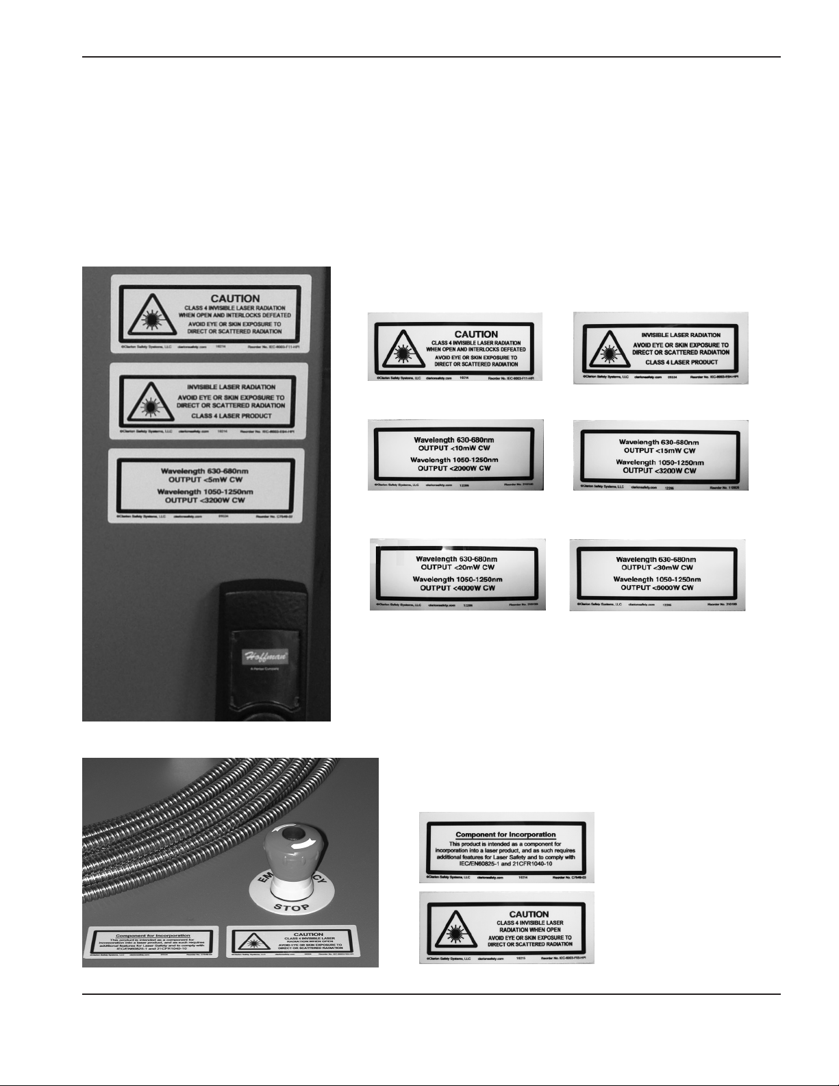
Laser safety warnings
It is the responsibility of the machine builder to meet all of the regulatory requirements for the final laser cutting system.
Nonetheless, many of the electronic and labeling requirements have been incorporated into the Hypertherm HyIntensity
Fiber Laser to facilitate the final laser cutting system compliance with regulatory requirements.
The following laser safety warning labels are located on the Hypertherm HyIntensity Fiber Laser when the Hypertherm
HyIntensity Fiber Laser leaves the Hypertherm factory.
Labels on the front door
On the 1.0 kW laser
(HFL010)
On the 2.0 kW laser
(HFL020)
Labels on the top cover
On the 1.5 kW laser
(HFL015)
On the 3.0 kW laser
(HFL030)
Hypertherm Fiber Laser Instruction Manual – 807090 Revision 3 S-5
Page 16
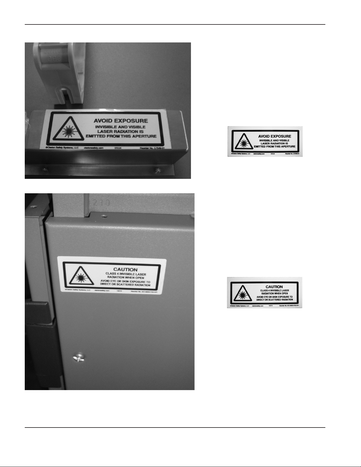
safety
Label on the Beam delivery outlet
Label on the left side
S-6 Hypertherm Fiber Laser Instruction Manual – 807090 Revision 3
Page 17
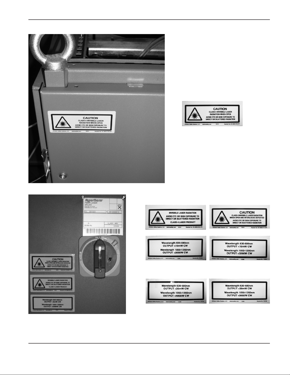
Label on the right side
safety
Labels on the rear door
On the 1.0 kW laser
(HFL010)
On the 2.0 kW laser
(HFL020)
On the 1.5 kW laser
(HFL015)
On the 3.0 kW laser
(HFL030)
Hypertherm Fiber Laser Instruction Manual – 807090 Revision 3 S-7
Page 18
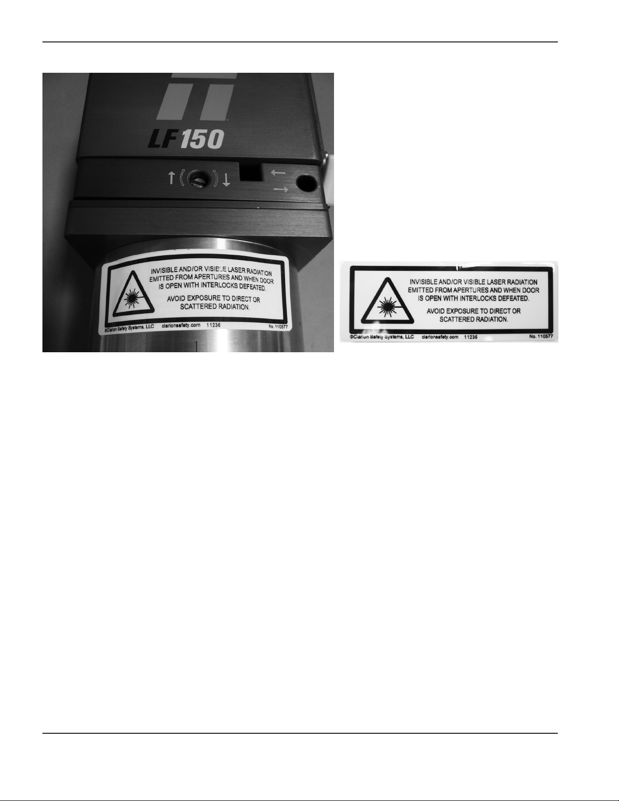
safety
Label on the laser head
S-8 Hypertherm Fiber Laser Instruction Manual – 807090 Revision 3
Page 19

safety
During installation it is vital that the laser hazard is fully managed. In particular, the machine builder is required to
implement the engineering requirements detailed in IEC/EN 60825-1. Based on the evaluation or certification of the
final laser cutting system, additional laser safety warnings may be provided by the machine builder or by the laser safety
officer at the installed site.
Health concerns
Personnel assigned to operate or maintain laser beam cutting equipment shall have been properly trained by the
machine builders representative or by a qualified instructor and shall understand the safety requirements of metal cutting
using lasers.
Laser safety eyewear (LSE)
Laser safety eyewear (LSE) is designed to reduce the amount of incident light of specific wavelengths to a safe level,
while transmitting sufficient light for good vision. As LSE often looks alike in style and color, it is important to specifically
check both the wavelength and optical density imprinted on all LSE prior to laser use, especially in multi-wavelength
facilities where more than one laser may be located. In the USA reference to ANSI Z136.1 is recommended for the
selection of appropriate eye wear to protect against reflections of laser radiation.
Acoustical noise
The noise generated by laser beam welding, cutting, or gouging may impair hearing. Hearing protection shall be worn
where the noise level exceeds limits as specified by the regulatory authority having jurisdiction Since operators and
nearby personnel can be exposed to noise levels in excess of 85 dB(A), it is important that their hearing be protected.
The most direct way to control excessive noise is to reduce the intensity at the source or install barriers in the final laser
cutting system between the source and the operator station(s). When engineering or administrative control methods
fail to bring noise exposure within levels established by the appropriate regulatory authority having jurisdiction, personal
protective devices such as earmuffs or earplugs shall be used. It is the responsibility of the machine builder and the
body responsible for the implementation of workplace / laser safety at the installed site to measure the acoustical noise
in application and ensure personnel are protected from noise levels that exceed limits.
Warning signs
Warning signs shall be posted in conspicuous areas to indicate laser and cutting hazards. The signs shall indicate the
need for the appropriate types of protective equipment.
Gas, fumes and air quality
Fumes and gases are generated by removal of metal from the workpiece being cut during laser beam cutting. The body
responsible for workplace / laser safety at the installed site needs to control the materials being cut. Before cutting any
unfamiliar materials or using any unfamiliar cleaning materials, the Material Safety Data Sheet (MSDS) shall be read to
determine whether any hazards may exist when the material removed will be converted to a gas by laser cutting.
Personnel shall not be exposed to concentrations of airborne contaminants above acceptable limits as established by
the authority having jurisdiction. The most direct way to control fumes and gases is by ventilation. Air Quality permits
may be needed to release fumes outside the building. Consult a local expert for information on local air quality permits,
ventilation and fume extraction. Where ventilation alone cannot protect personnel, appropriate personal respiratory
protection shall be used as required by the authority having jurisdiction. Where respirators are employed, requirements
for the selection and use of respirators shall include, as a minimum, the following:
A. Written procedures for the proper care, use, maintenance, and storage of respirators shall be provided, and the
employer shall ensure that these procedures are followed. These procedures shall be developed and set down
in writing in consultation with the joint health and safety committee or the health and safety representative, as
applicable; and made readily accessible, along with related schedules, to the welder andwelding personnel.
Hypertherm Fiber Laser Instruction Manual – 807090 Revision 3 S-9
Page 20

safety
B. The OEM laser cutting end product recommended maintenance and cleaning schedules and procedures shall
be followed.
C. Adequate and suitable storage facilities for respirators shall be provided.
D. A person with the appropriate skills and knowledge shall be assigned to examine respirators and carry out the
tests or procedures necessary to ensure that they serve their intended purpose; and ensure that the respirators
fit the individual workers correctly and are appropriate for their intended purpose.
E. The employer shall provide training and instruction for workers and supervisors on the proper use, care,
maintenance, and storage of respirators.
For fume and gases air sampling, where concentrations of airborne fume contaminants are to be determined by
sampling of the atmosphere, sampling shall be tested using the NIOSH methodology, other recognized methods, or the
guidelines of the authority having jurisdiction. When a helmet is worn, the samples shall be collected inside the helmet
in the operator’s breathing zone. The occupational exposure limits shall comply with the regulatory authority having
jurisdiction. Contaminant and fume analysis in the lab is covered under two areas:
A. Total welding fume particulate (mg/m3).
B. An elemental analysis of each contaminant (mg/m3). The contaminant particulate and fume testing is important
to determine the exposure risk to personnel.
Confined spaces
Confined spaces are defined specifically in the codes and regulations that apply to each work project. Confined spaces
need to be considered when the access or egress of personnel is restricted and there is a potential for the accumulation
of a hazardous gas, fume, vapor, and dust, or the development of an oxygen-deficient or oxygen-enriched atmosphere
that is likely to affect the health and safety of a worker.
If needed, the body responsible for the implementation of workplace / laser safety at the installed site shall have written
rescue procedures for confined space emergencies. Before the operator or service personnel enters a confined
space to undertake any welding, cutting, or allied process, the personnel shall be informed of and understand the
hazards of the confined space and receive instruction on safe procedures for entering, working in, and exiting from
theconfinedspace.
Before a person enters a confined space, a leak test should be done on all joints of any hose or pipelines that have the
potential to introduce gases into the confined space. This leak test is done in order to eliminate the possibility of gases
being introduced into the confined space.
S-10 Hypertherm Fiber Laser Instruction Manual – 807090 Revision 3
Page 21

safety
Oxygen gas distribution for laser cutting
Oxygen distribution system including connections and valves shall be approved by the regulatory authority having
jurisdiction.
• Each outlet on the service piping from which oxygen is withdrawn to supply a portable outlet header shall be
equipped with a readily accessible shutoff valve.
• Each service outlet on portable outlet headers shall be provided with a check valve, a readily accessible shutoff
valve, and a detachable outlet seal cap that is chained or otherwise attached to the body of the valve.
• Master shutoff valves for oxygen shall be provided at the entry end of the portable outlet header.
• Portable outlet headers for fuel gas service shall be provided with an approved hydraulic backpressure valve
installed at the inlet and preceding the service outlets, unless an approved pressure-reducing regulator, an
approved backflow check valve, or an approved hydraulic backpressure valve is installed at each outlet. Outlets
provided on headers for oxygen service may be fitted for use with pressure-reducing regulators or for direct
hoseconnection.
• Hose for oxygen-fuel gas service shall meet the requirements of RMA IP-7 and CGA E-1.
• Cylinder manifolds, shutoff valves, pressure-reducing regulators, backpressure valves, hoses and connections
shall be installed under the supervision of someone properly trained in their assembly and use.
In North America, hose diameters of 19 mm (3/4 in) or smaller are color-coded green for oxygen and red for fuel
gases (acetylene, liquefied petroleum gases (LPG), natural gas, hydrogen, etc.). Black hose is used for inert gases,
compressed air, and water services.
Note: ISO standard colors are blue for oxygen hose and orange for LPG hose.
Public exhibitions and demonstrations
Safety precautions specific to welding and cutting performed at public demonstrations and exhibits shall protect
viewers, demonstrators, and the public. Installation and operation of welding, cutting, and related equipment shall
be under the supervision of a competent person designated to ensure the safety of the public. The site shall be
so constructed, equipped, and operated as to minimize the possibility of injury to viewers at the site. Materials and
equipment on-site shall be located so as not to interfere with evacuation of people during an emergency. Sites shall be
provided with an appropriate type of portable fire extinguisher. Combustible materials at the site shall be shielded from
flames, sparks, and molten metal or moved to a safe distance, i.e., 15 m (50 ft). The fire department shall be notified in
advance of the public exhibition and demonstration. The public shall be shielded from flames, flying sparks, molten metal,
harmful laser radiation, inhalation of hazardous concentrations of fumes and gases and contact with live electrical arts.
Large area viewing
For large area viewing, such as training, demonstrations, shows, and certain automatic laser welding and cutting
operations, a large filter window or curtain may be used rather than individual helmets, hand shields, or goggles. It is
important to specifically check both the wavelength and optical density for a large filter window or curtain. Acombination
of windows or curtains and laser safety eye wear (LSE) may be used.
Hypertherm Fiber Laser Instruction Manual – 807090 Revision 3 S-11
Page 22

safety
Training
The laser safety and basic safety training shall be in accordance with the requirements of the authority having
jurisdiction. The course contents should include, as a minimum, elements covering:
A. laser safety
B. basic safety
C. hazard identification, including:
a. electrical hazards
b. fire protection and prevention
c. burns
d. radiation
e. fumes and gases
f. noise
g. explosions
D. hazard controls
E. personal protective equipment
F. process-specific welding and cutting safety
G. ergonomic issues
H. care and maintenance of OEM laser cutting end product
Additional training shall be provided on the following subjects if applicable to the nature of work being performed:
A. elevated work and fall protection
B. material handling (basic rigging, hoisting, forklift, etc.)
C. confined spaces
D. welding or cutting of drums and containers
E. work permit systems and policies
S-12 Hypertherm Fiber Laser Instruction Manual – 807090 Revision 3
Page 23

PRODUCT STEWARDSHIP
Introduction
Hypertherm maintains a global Regulatory Management
System to ensure that products comply with regulatory
and environmental requirements.
National and local safety regulations
National and Local safety regulations shall take
precedence over any instructions provided with the
product. The product shall be imported, installed,
operated and disposed of in accordance with national
and local regulations applicable to the installed site.
Certification test marks
Certified products are identified by one or more
certification test marks from accredited testing
laboratories. The certification test marks are located
onornear the data plate.
Each certification test mark means that the product and
its safety-critical components conform to the relevant
national safety standards as reviewed and determined by
that testing laboratory. Hypertherm places a certification
test mark on its products only after that product is
manufactured with safety-critical components that have
been authorized by the accredited testing laboratory.
Once the product has left the Hypertherm factory,
the certification test marks are invalidated if any of the
following occurs:
• Theproductismodifiedinamannerthatcreates
a hazard or non-conformance with the applicable
standards.
• Safety-criticalcomponentsarereplacedwith
unauthorized spare parts.
• Anyunauthorizedassembly,oraccessorythatusesor
generates a hazardous voltage is added.
• Thereisanytamperingwithasafetycircuitorother
feature that is designed into the product as part of the
certification, or otherwise.
CE marking constitutes a manufacturer’s declaration
of conformity to applicable European directives and
standards. Only those versions of Hypertherm products
with a CE Marking located on or near the data plate
have been tested for compliance with the European Low
Voltage Directive and the European EMC Directive. EMC
filters needed to comply with the European EMC Directive
are incorporated within versions of the power supply with
a CE Marking.
Certificates of compliance for Hypertherm products are
available fromthe Downloads Library on the Hypertherm
web site at
https://www.hypertherm.com.
Differences in national standards
Nations may apply different performance, safety or other
standards. National differences in standards include, but
are not limited to:
• Voltages
• Plugandcordratings
• Languagerequirements
• Electromagneticcompatibilityrequirements
These differences in national or other standards may
make it impossible or impractical for all certification test
marks to be placed on the same version of a product.
For example, the CSA versions of Hypertherm’s products
do not comply with European EMC requirements, and
therefore do not have a CE marking on the data plate.
Countries that require CE marking or have compulsory
EMC regulations must use CE versions of Hypertherm
products with the CE marking on the data plate. These
include, but are not limited to:
• Australia
• NewZealand
• CountriesintheEuropeanUnion
• Russia
It is important that the product and its certification test
mark be suitable for the end-use installation site. When
Hypertherm products are shipped to one country for
export to another country; the product must be configured
and certified properly for the end-use site.
Safe installation and use of shape cutting equipment
IEC 60974-9, titled Arc Welding Equipment – Installation
and use, provides guidance in the safe installation and
use of shape cutting equipment and the safe performance
of cutting operations. The requirements of national and
local regulations shall be taken into consideration during
installation, including, but not limited to, grounding or
Hypertherm Fiber Laser Instruction Manual – 807090 Revision 3 PS-1
Page 24

product stewardship
protective earth connections, fuses, supply disconnecting
device, and type of supply circuit. Read these instructions
before installing the equipment. The first and most
important step is the safety assessment of the installation.
The safety assessment must be performed by an expert,
and determines what steps are necessary to create a safe
environment, and what precautions should be adopted
during the actual installation and operation.
Procedures for periodic inspection and testing
Where required by local national regulations,
IEC60974-4 specifies test procedures for periodic
inspection and after repair or maintenance, to ensure
electrical safety for plasma cutting power sources built
in conformity with IEC 60974-1. Hypertherm performs
the continuity of the protective circuit and insulation
resistance tests in the factory as non-operating tests.
The tests are performed with the power and ground
connections removed.
Hypertherm also removes some protective devices
that would cause false test results. Where required by
local national regulations, a label shall be attached to
the equipment to indicate that it has passed the tests
prescribed by IEC60974-4. The repair report shall
indicate the results of all tests unless an indication is
made that a particular test has not been performed.
Qualification of test personnel
Electrical safety tests for shape cutting equipment can
be hazardous and shall be carried out by an expert in the
field of electrical repair, preferably someone also familiar
with welding, cutting, and allied processes. The safety
risks to personnel and equipment, when unqualified
personnel are performing these tests, may be much
greater than the benefit of periodic inspection and testing.
Hypertherm recommends that only visual inspection
be performed unless the electrical safety tests are
specifically required by local national regulations in the
country where the equipment is installed.
Residual current devices (RCDs)
In Australia and some other countries, local codes may
require the use of a Residual Current Devices (RCD)
when portable electrical equipment is used in the
workplace or at construction sites to protect operators
from electrical faults in the equipment. RCDs are
designed to safely disconnect the mains electrical supply
when an imbalance is detected between the supply
and return current (there is a leakage current to earth).
RCDs are available with both fixed and adjustable trip
currents between 6to 40 milliamperes and a range of trip
times up to 300milliseconds selected for the equipment
installation, application and intended use. Where RCDs
are used, the trip current and trip time on RCDs should
be selected or adjusted high enough to avoid nuisance
tripping during normal operation of the plasma cutting
equipment and low enough in the extremely unlikely event
of an electrical fault in the equipment to disconnect the
supply before the leakage current under a fault condition
can pose a life threatening electrical hazard to operators.
To verify that the RCDs continue to function properly
over time, both the trip current and the trip time should
be tested periodically. Portable electrical equipment
and RCDs used in commercial and industrial areas in
Australia and New Zealand are tested to the Australian
standard AS/ NZS3760. When you test the insulation
of plasma cutting equipment to AS/ NZS 3760, measure
the insulation resistance according to Appendix B of
the standard, at 250VDC with the power switch in the
ON position to verify proper testing and to avoid the
false failure of the leakage current test. False failures
are possible because the metal oxide varistors (MOVs)
and electromagnetic compatibility (EMC) filters, used to
reduce emissions and protect the equipment from power
surges, may conduct up to 10milliamperes leakage
current to earth under normal conditions.
If you have any questions regarding the application or
interpretation of any IEC standards described here, you
are required to consult with an appropriate legal or other
advisor familiar with the International Electrotechnical
standards, and shall not rely on Hypertherm in any
respect regarding the interpretation or application of such
standards.
PS-2 Hypertherm Fiber Laser Instruction Manual – 807090 Revision 3
Page 25

Higher-level systems
When a system integrator adds additional equipment;
such as cutting tables, motor drives, motion controllers
or robots; to a Hypertherm plasma cutting system, the
combined system may be considered a higher-level
system. A higher-level system with hazardous moving
parts may constitute industrial machinery or robotic
equipment, in which case the OEM or end-use customer
may be subject to additional regulations and standards
than those relevant to the plasma cutting system as
manufactured by Hypertherm.
It is the responsibility of the end-use customer and the
OEM to perform a risk assessment for the higher-level
system, and to provide protection against hazardous
moving parts. Unless the higher-level system is certified
when the OEM incorporates Hypertherm products into it,
the installation also may be subject to approval by local
authorities. Seek advice from legal counsel and local
regulatory experts if you are uncertain about compliance.
External interconnecting cables between component
parts of the higher level system must be suitable for
contaminants and movement as required by the final end
use installation site. When the external interconnecting
cables are subject to oil, dust, water, or other
contaminants, hard usage ratings may be required.
Product stewardshiP
When external interconnecting cables are subject to
continuous movement, constant flexing ratings may be
required. It is the responsibility of the end-use customer
or the OEM to ensure the cables are suitable for the
application. Since there are differences in the ratings and
costs that can be required by local regulations for higher
level systems, it is necessary to verify that any external
interconnecting cables are suitable for the end-use
installation site.
Hypertherm Fiber Laser Instruction Manual – 807090 Revision 3 PS-3
Page 26

product stewardship
PS-4 Hypertherm Fiber Laser Instruction Manual – 807090 Revision 3
Page 27

ENVIRONMENTAL STEWARDSHIP
Introduction
The Hypertherm Environmental Specification requires
RoHS, WEEE and REACH substance information to be
provided by Hypertherm’s suppliers.
Product environmental compliance does not address the
indoor air quality or environmental release of fumes by the
end user. Any materials that are cut by the end user are
not provided by Hypertherm with the product. The end
user is responsible for the materials being cut as well as
for safety and air quality in the workplace. The end user
must be aware of the potential health risks of the fumes
released from the materials being cut and comply with all
local regulations.
National and local environmental regulations
National and local environmental regulations shall take
precedence over any instructions contained in this manual.
The product shall be imported, installed, operated and
disposed of in accordance with all national and local
environmental regulations applicable to the installed site.
The European Environmental regulations are discussed
later in TheWEEE Directive.
The RoHS directive
Hypertherm is committed to complying with all applicable
laws and regulations, including the European Union
Restriction of Hazardous Substances (RoHS) Directive
that restricts the use of hazardous materials in electronics
products. Hypertherm exceeds RoHS Directive
compliance obligations on a global basis.
Hypertherm continues to work toward the reduction of
RoHS materials in our products, which are subject to the
RoHS Directive, except where it is widely recognized that
there is no feasible alternative.
Declarations of RoHS Conformity have been prepared
for the current CE versions of Powermax plasma cutting
systems manufactured by Hypertherm. There is also
a “RoHS mark” on the Powermax CE versions below
the “CE Marking” on the data plate of CE versions
of Powermax series units shipped since 2006. Parts
used in CSA versions of Powermax and other products
manufactured by Hypertherm that are either out of scope
or exempt from RoHS are continuously being converted to
RoHS compliance in anticipation of future requirements.
Proper disposal of Hypertherm products
Hypertherm plasma cutting systems, like all electronic
products, may contain materials or components, such
as printed circuit boards, that cannot be discarded
with ordinary waste. It is your responsibility to dispose
of any Hypertherm product or component part in an
environmentally acceptable manner according to national
and localcodes.
• IntheUnitedStates,checkallfederal,state,andlocal
laws.
• IntheEuropeanUnion,checktheEUdirectives,
national, and local laws. For more information, visit www.
hypertherm.com/weee.
• Inothercountries,checknationalandlocallaws.
• Consultwithlegalorothercomplianceexpertswhen
appropriate.
The WEEE directive
On January 27, 2003, the European Parliament and the
Council of the European Union authorized Directive
2002/96/EC or WEEE (Waste Electrical and Electronic
Equipment).
As required by the legislation, any Hypertherm product
covered by the directive and sold in the EU after August
13, 2005 is marked with the WEEE symbol. This directive
encourages and sets specific criteria for the collection,
handling, and recycling of EEE waste. Consumer and
business-to-business wastes are treated differently
(all Hypertherm products are considered business-tobusiness). Disposal instructions for the CE versions of
Powermax plasma systems can be found at
www.hypertherm.com/weee.
The URL is printed on the symbol-only warning label for
each of these CE version Powermax series units shipped
since 2006. The CSA versions of Powermax and other
products manufactured by Hypertherm are either out of
scope or exempt from WEEE.
Hypertherm Fiber Laser Instruction Manual – 807090 Revision 3 ES-1
Page 28

environmental stewardship
The REACH regulation
The REACH regulation (1907/2006), in force since
June1, 2007, has an impact on chemicals available to the
European market. The REACH regulation requirements for
component manufacturers states that the component shall
not contain more than 0.1% by weight of the Substances
of Very High Concern (SVHC).
Component manufacturers and other downstream users,
such as Hypertherm, are obligated to obtain assurances
from its suppliers that all chemicals used in or on
Hypertherm products will have a European Chemical
Agency (ECHA) registration number. To provide chemical
information as required by the REACH regulation,
Hypertherm requires suppliers to provide REACH
declarations and identify any known use of REACH
SVHC. Any use of SVHC in amounts exceeding 0.1%
w/w of the parts has been eliminated. The MSDS contains
a full disclosure of all substances in the chemical and can
be used to verify REACH SVHC compliance.
The lubricants, sealants, coolants, adhesives, solvents,
coatings and other preparations or mixtures used by
Hypertherm in, on, for, or with its shape cutting equipment
are used in very small quantities (except the coolant)
and are commercially available with multiple sources
that can and will be replaced in the event of a supplier
problem associated with REACH Registration or REACH
Authorization (SVHCs).
Proper handling and safe use of chemicals
Chemical Regulations in the USA, Europe, and other
locations require that Material Safety Data Sheets (MSDS)
be made available for all chemicals. The list of chemicals
is provided by Hypertherm. The MSDS are for chemicals
provided with the product and other chemicals used in
or on the product. MSDS can be downloaded from the
Downloads Library on the Hypertherm web site at https://
www.hypertherm.com. On the Search screen, insert
MSDS in the document title and click on Search.
Fumes emission and air quality
Note: The following information on air quality is
intended for general information only and should
not be used as a substitute for reviewing and
implementing applicable government regulations
or legal standards in the country where the cutting
equipment will be installed and operated.
In the USA, the National Institute for Occupational Safety
and Health (NIOSH) Manual of Analytical Methods
(NMAM) is a collection of methods for sampling and
analyzing contaminants in workplace air. Methods
published by others, such as OSHA, MSHA, EPA, ASTM,
ISO or commercial suppliers of sampling and analytical
equipment, may have advantages over NIOSH methods.
For example, ASTM Practice D 4185 is a standard
practice for the collection, dissolution, and determination
of trace metals in workplace atmospheres. The sensitivity,
detection limit, and optimum working concentrations
for 23 metals are listed in ASTMD4185. An industrial
hygienist should be used to determine the optimum
sampling protocol, considering analytical accuracy, cost,
and optimum sample number. Hypertherm uses a third
party industrial hygienist to perform and interpret air quality
testing results taken by air sampling equipment positioned
at operator stations in Hypertherm buildings where plasma
cutting tables are installed and operated.
Where applicable, Hypertherm also uses a third party
industrial hygienist to obtain air and water permits.
If you are not fully aware and up to date on all applicable
government regulations and legal standards for the
installation site, you should consult a local expert prior to
purchasing, installing, and operating theequipment.
In the USA, OSHA does not require Material Safety
Data Sheets for articles such as electrodes, swirl rings,
retaining caps, nozzles, shields, deflectors and other solid
parts of the torch.
Hypertherm does not manufacture or provide the materials
that are cut and has no knowledge whether the fumes
released from materials that are cut will pose a physical
hazard or health risk. Please consult with your supplier or
other technical advisor if you need guidance concerning
the properties of the material you will cut using a
Hypertherm product.
ES-2 Hypertherm Fiber Laser Instruction Manual – 807090 Revision 3
Page 29

Electromagnetic Compatibility (EMC)
Introduction
Hypertherm’s CE-marked equipment is built in compliance
with standard EN60974-10. The equipment should be
installed and used in accordance with the information
below to achieve electromagnetic compatibility.
The limits required by EN60974-10 may not be adequate
to completely eliminate interference when the affected
equipment is in close proximity or has a high degree of
sensitivity. In such cases it may be necessary to use other
measures to further reduce interference.
This cutting equipment is designed for use only in an
industrial environment.
Installation and use
The user is responsible for installing and using the cutting
equipment according to the manufacturer’s instructions.
If electromagnetic disturbances are detected then it shall
be the responsibility of the user to resolve the situation
with the technical assistance of the manufacturer. In some
cases this remedial action may be as simple as earthing
the cutting circuit, see Earthing of the workpiece. In other
cases, it could involve constructing an electromagnetic
screen enclosing the power source and the work
complete with associated input filters. In all cases,
electromagnetic disturbances must be reduced to the
point where they are no longer troublesome.
Assessment of area
Before installing the equipment, the user shall make an
assessment of potential electromagnetic problems in
the surrounding area. The following shall be taken into
account:
a. Other supply cables, control cables, signaling and
telephone cables; above, below and adjacent to the
cutting equipment.
b. Radio and television transmitters and receivers.
c. Computer and other control equipment.
d. Safety critical equipment, for example guarding of
industrial equipment.
e. Health of the people around, for example the use of
pacemakers and hearing aids.
f. Equipment used for calibration or measurement.
g. Immunity of other equipment in the environment. User
shall ensure that other equipment being used in the
environment is compatible. This may require additional
protection measures.
h. Time of day that cutting or other activities are to be
carried out.
The size of the surrounding area to be considered
will depend on the structure of the building and other
activities that are taking place. The surrounding area may
extend beyond the boundaries of the premises.
Methods of reducing emissions
Mains supply
Cutting equipment must be connected to the mains
supply according to the manufacturer’s recommendations.
If interference occurs, it may be necessary to take
additional precautions such as filtering of the mains
supply.
Compliance Information EMC-1
1/12
Page 30

ELECTROMAGNETIC COMPATIBILITY
Consideration should be given to shielding the supply
cable of permanently installed cutting equipment, in
metallic conduit or equivalent. Shielding should be
electrically continuous throughout its length. The shielding
should be connected to the cutting mains supply so that
good electrical contact is maintained between the conduit
and the cutting power source enclosure.
Maintenance of cutting equipment
The cutting equipment must be routinely maintained
according to the manufacturer’s recommendations. All
access and service doors and covers should be closed
and properly fastened when the cutting equipment is in
operation. The cutting equipment should not be modified
in any way, except as set forth in and in accordance with
the manufacturer’s written instructions.
Cutting cables
The cutting cables should be kept as short as possible
and should be positioned close together, running at or
close to the floor level.
Equipotential bonding
Bonding of all metallic components in the cutting
installation and adjacent to it should be considered.
However, metallic components bonded to the workpiece
will increase the risk that the operator could receive a
shock by touching these metallic components and the
electrode (nozzle for laser heads) at the same time.
Earthing of the workpiece
Where the workpiece is not bonded to earth for electrical
safety, nor connected to earth because of its size and
position, for example, ship’s hull or building steel work,
a connection bonding the workpiece to earth may
reduce emissions in some, but not all instances. Care
should be taken to prevent the earthing of the workpiece
increasing the risk of injury to users, or damage to other
electrical equipment. Where necessary, the connection
of the workpiece to earth should be made by a direct
connection to the workpiece, but in some countries where
direct connection is not permitted, the bonding should be
achieved by suitable capacitances selected according to
national regulations.
Note: The cutting circuit may or may not be earthed for
safety reasons. Changing the earthing arrangements
should only be authorized by a person who is competent
to assess whether the changes will in crease the risk of
injury, for example, by allowing parallel cutting current
return paths which may damage the earth circuits of other
equipment. Further guidance is provided in IEC 60974-9,
Arc Welding Equip ment, Part 9: Installation and Use.
Screening and shielding
Selective screening and shielding of other cables and
equipment in the surrounding area may alleviate problems
of interference. Screening of the entire cutting system
may be considered for special applications.
The operator should be insulated from all such bonded
metallic components.
EMC-2 Compliance Information
1/12
Page 31

Warranty
Attention
Genuine Hypertherm parts are the factory-recommended
replacement parts for your Hypertherm system. Any
damage or injury caused by the use of other than genuine
Hypertherm parts may not be covered by the Hypertherm
warranty, and will constitute misuse of the Hypertherm
Product.
You are solely responsible for the safe use of the Product.
Hypertherm does not and cannot make any guarantee
or warranty regarding the safe use of the product in your
environment.
General
Hypertherm, Inc. warrants that its Products shall be
free from defects in materials and workmanship for the
specific periods of time set forth herein and as follows:
if Hypertherm is notified of a defect (i)with respect to
the plasma power supply within a period of two (2) years
from the date of its delivery to you, with the exception of
Powermax brand power supplies, which shall be within a
period of three (3) years from the date of delivery to you,
and (ii)with respect to the torch and leads within a period
of one (1) year from its date of delivery to you, and with
respect to torch lifter assemblies within a period of one
(1) year from its date of delivery to you, and with respect
to Automation products one (1) year from its date of
delivery to you, with the exception of the EDGE Pro CNC
and ArcGlide THC, which shall be within a period of two
(2) years from the date of delivery to you, and (iii)with
respect to HyIntensity fiber laser components within a
period of two (2) years from the date of its delivery to
you, with the exception of laser heads and beam delivery
optical cables, which shall be within a period of one (1)
year from its date of delivery to you.
Hypertherm provides repair, replacement or adjustment
of the Product as the sole and exclusive remedy, if and
only if the warranty set forth herein properly is invoked
and applies. Hypertherm, at its sole option, shall repair,
replace, or adjust, free of charge, any defective Products
covered by this warranty which shall be returned with
Hypertherm’s prior authorization (which shall not be
unreasonably withheld), properly packed, to Hypertherm’s
place of business in Hanover, New Hampshire, or to an
authorized Hypertherm repair facility, all costs, insurance
and freight pre paid by the customer. Hypertherm shall
not be liable for any repairs, replacement, or adjustments
of Products covered by this warranty, except those made
pursuant to this paragraph and with Hypertherm’s prior
written consent.
The warranty set forth above is exclusive and is in lieu
of all other warranties, express, implied, statutory, or
otherwise with respect to the Products or as to the
results which may be obtained therefrom, and all implied
warranties or conditions of quality or of merchantability
orfitness for a particular purpose or against infringement.
The foregoing shall constitute the sole and exclusive
remedy for any breach by Hypertherm of its warranty.
Distributors/OEMs may offer different or additional
warranties, but Distributors/OEMs are not authorized
togive any additional warranty protection to you or make
any representation to you purporting to be binding upon
Hypertherm.
This warranty shall not apply to any Powermax brand
power supplies that have been used with phase
converters. In addition, Hypertherm does not warranty
systems that have been damaged as a result of poor
power quality, whether from phase converters or incoming
line power. This warranty shall not apply to any product
which has been incorrectly installed, modified, or
otherwise damaged.
Compliance Information W-1
1/12
Page 32

WARRANTY
Patent indemnity
Except only in cases of products not manufactured by
Hypertherm or manufactured by a person other than
Hypertherm not in strict conformity with Hypertherm’s
specifications and in cases of designs, processes,
formulae, or combinations not developed or purported
to be developed by Hypertherm, Hypertherm will have
the right to defend or settle, at its own expense, any
suit or proceeding brought against you alleging that
the use of the Hypertherm product, alone and not in
combination with any other product not supplied by
Hypertherm, infringes any patent of any third party. You
shall notify Hypertherm promptly upon learning of any
action or threatened action in connection with any such
alleged infringement (and in any event no longer than
fourteen (14) days after learning of any action or threat of
action), and Hypertherm’s obligation to defend shall be
conditioned upon Hypertherm’s sole control of, and the
indemnified party’s cooperation and assistance in, the
defense of the claim.
Limitation of liability
In no event shall Hypertherm be liable to any
person or entity for any incidental, consequential
direct, indirect, punitive or exemplary damages
(including but not limited to lost profits) regardless
of whether such liability is based on breach of
contract, tort, strict liability, breach of warranty,
failure of essential purpose, or otherwise, and
even if advised of the possibility of such damages.
Insurance
At all times you will have and maintain insurance in such
quantities and types, and with coverage sufficient and
appropriate to defend and to hold Hypertherm harmless
in the event of any cause of action arising from the use
ofthe products.
Transfer of rights
You may transfer any remaining rights you may have
hereunder only in connection with the sale of all or
substantially all of your assets or capital stock to a
successor in interest who agrees to be bound by all of
the terms and conditions of this Warranty. Within thirty
(30) days before any such transfer occurs, you agree to
notify in writing Hypertherm, which reserves the right of
approval. Should you fail timely to notify Hypertherm and
seek its approval as set forth herein, the Warranty set
forth herein shall be null and void and you will have no
further recourse against Hypertherm under the Warranty
or otherwise.
National and local codes
National and local codes governing plumbing and
electrical installation shall take precedence over any
instructions contained in this manual. In no event shall
Hypertherm be liable for injury to persons or property
damage by reason of any code violation or poor work
practices.
Liability cap
In no event shall Hypertherm’s liability, if any,
whether such liability is based on breach of
contract, tort, strict liability, breach of warranties,
failure of essential purpose or otherwise, for any
claim, action, suit or proceeding (whether in court,
arbitration, regulatory proceeding or otherwise)
arising out of or relating to the use of the Products
exceed in the aggregate the amount paid for the
Products that gave rise to such claim.
W-2 Compliance Information
1/12
Page 33

Section 1
SPECIFICATIONS
Fiber laser supply
Overview
The HyIntensity Fiber Laser (HFL) is a laser system based on all solid state components. The fiber laser supply contains
two to six laser engines and a beam combiner unit. Incoming electricity is converted to optical power by single emitter
based pump laser diodes in each engine, which is converted to a high brightness infrared (non-visible) laser beam.
Light from each of the laser engines enters the beam combiner unit which funnels the light into a single output fiber.
This configuration has a wall plug electrical to optical output power efficiency greater than 28%. All of the optical
components are water cooled to provide stable operation. A dehumidifier in the fiber laser supply maintains the humidity
level inside the cabinet enclosure.
Fiber laser supplies
Part number Description
051041 HFL010 — 1.0 kW fiber laser supply, with the fiber coupling unit, 400-480 VAC, 50/60 Hz
051042 HFL010 — 1.0 kW fiber laser supply, without the fiber coupling unit, 400-480 VAC, 50/60 Hz
051023 HFL015 — 1.5 kW fiber laser supply, with the fiber coupling unit, 400-480 VAC, 50/60 Hz
051043 HFL015 — 1.5 kW fiber laser supply, without the fiber coupling unit, 400-480 VAC, 50/60 Hz
051039 HFL020 — 2.0 kW fiber laser supply, with the fiber coupling unit, 400-480 VAC, 50/60 Hz
051044 HFL020 — 2.0 kW fiber laser supply, without the fiber coupling unit, 400-480 VAC, 50/60 Hz
051048 HFL030 — 3.0 kW fiber laser supply, with the fiber coupling unit, 440-480 VAC 50/60 Hz
051053 HFL030 — 3.0 kW fiber laser supply, without the fiber coupling unit, 440-480 VAC 50/60 Hz
051049 HFL030 — 3.0 kW fiber laser supply, with the fiber coupling unit, 380-400 VAC 50/60 Hz
051052 HFL030 — 3.0 kW fiber laser supply, without the fiber coupling unit, 380-400 VAC 50/60 Hz
HyIntensity Fiber Laser Instruction Manual – 807090 Revision 3 1-1
Page 34

SpecificationS
Requirements
Electrical
HFL010, 015, 020 Input power ..................................... 400-480 VAC, 50/60 Hz (+/- 10%), 3 phase, 10 KVa
HFL030 (051048 and 051053) Input power ............. 440-480 VAC, 50/60 Hz (+/- 10%), 3 phase, 15 KVa
HFL030 (051049 and 051052) Input power ............. 380-400 VAC, 50/60 Hz (+/- 10%), 3 phase, 15 KVa
Note: The customer should permanently wire the fiber laser supply using a 3 phase, 30 amp disconnect.
Input/output (I/O)
Discrete I/O ......................................................................... Out: permanently wired, +24 VDC relay, 100 mA
In: optically isolated, +24 VDC
Analog I/O ........................................................................... 0-10 VDC
Coolant ............................................................................... See Chiller requirements later in this section.
Environmental
This equipment is intended for indoor use only
Operating temperature range ......................................... 0° C to 40° C (32° F to 104° F)
Humidity ............................................................................... 95% relative humidity, non-condensing
Altitude ................................................................................. 2000 m (6562 feet) maximum
Safety interlocks
External emergency stop (E-Stop) switch with (2) NO contacts (see the Installation section for details)
External door interlock switch with (2) NO contacts
Key switch that is only removable in the OFF position
Momentary switch with Indicator and (1) NO contact
Personal protection equipment
Safety glasses..................................................................... OD 7+ @1040 – 1100 nm
Machine guards .................................................................. Proper guards installed to protect against diffuse and specular
laserreflections
1-2 HyIntensity Fiber Laser Instruction Manual – 807090 Revision 3
Page 35

Optical specifications
Cutting laser
Operating mode ................................................................. Continuous wave (CW)
Beam shape ........................................................................ Circular
Wavelength ......................................................................... 1070 nm (+/- 10 nm)
Rated output power (CW):
H FL 010 ................................................................................ 1000 watts
HFL015 ................................................................................ 1500 watts
HFL020 ................................................................................ 2000 watts
HFL030 ................................................................................ 3000 watts
Beam diameter at the focusing lens .............................. 6-8 mm with the 60 mm collimator
10-12 mm with the 100 mm collimator
Focusing lens ...................................................................... 150 mm effective focal length (EFL)
Laser classification ............................................................ Class 4
Pointing laser
Operating mode ................................................................. Continuous wave (CW)
Beam shape ........................................................................ Circular
Wavelength ......................................................................... 630 – 680 nm
Rated output power (CW)
H FL 010 ................................................................................ <10 mW
HFL015 ................................................................................ <15 mW
HFL020 ................................................................................ <20 mW
HFL030 ................................................................................ <30 mW
Beam diameter at the focusing lens .............................. 6
Beam diameter ................................................................... 9 mm
Laser classification ............................................................ Class 3B
SpecificationS
HyIntensity Fiber Laser Instruction Manual – 807090 Revision 3 1-3
Page 36

SpecificationS
Dimensions – HFL010, HFL015, and HFL020
171.45 mm
1174.5 mm
46.24 in
822.9 mm
32.4 in
6.75 in
HFL010 — 185 kg (410 lbs)
HFL015 — 204 kg (450 lbs)
HFL020 — 226 kg (500 lbs)
Front view
889.0 mm
35.0 in
183.13 mm
Side view
7.21 in
1-4 HyIntensity Fiber Laser Instruction Manual – 807090 Revision 3
Page 37

Dimensions – HFL030
SpecificationS
825 mm
32.5 in
241 mm
9.5 in
1295 mm
51.0 in
283.5 kg
625 lb
Front view
889 mm
35 in
183.13 mm 7.21 in
Side view
HyIntensity Fiber Laser Instruction Manual – 807090 Revision 3 1-5
Page 38

SpecificationS
LF150 laser head – 051025
Overview
The LF150 is designed to process material with the HyIntensity Fiber Laser cutting system. The optical design
accommodates one 35 mm diameter lens at 150 mm EFL to cover the intended material type and thickness range.
Capacitive height sensing between the nozzle and the work piece allows accurate and responsive height positioning.
The laser head is protected by a collision mount for lateral and vertical collisions between the nozzle and work piece.
The optical path between the collimator and laser head is sealed to prevent particulate and moisture contamination
of the optical surfaces. A single cable connects the laser head to the laser head controller and all process signals are
communicated back to the fiber laser supply over the Hypernet communications link.
1-6 HyIntensity Fiber Laser Instruction Manual – 807090 Revision 3
Page 39

Mounting dimensions
171.5 mm
6.75 in
152.4 mm
6.00 in
SpecificationS
31.5 mm
1.24 in
57.2 mm
2.25 in
Diameter 6.6 mm (0.26 in) through hole (4 places)
Diameter 11.0 mm (0.43 in) counterbore
Diameter 6.8 mm (0.27 in) through hole (4 places)
Diameter 11.1 mm (0.44 in) counterbore
101.6 mm
4.0 in
Diameter
108.0 mm
4.25 in
Top view
Diameter 3.0 mm
(0.118 in)
(2 places)
45.0 mm
1.77 in
7.8 kg
17.2 lb
90.0 mm
3.54 in
32.0 mm
1.26 in
36.0 mm
1.42 in
50.0 mm
1.97 in
62.7 mm
2.47 in
269.8 mm
10.62 in
Full extension
Front view Rear view
HyIntensity Fiber Laser Instruction Manual – 807090 Revision 3 1-7
Page 40

SpecificationS
Collimator dimensions
The collimator is installed onto the laser head in the Installation section of this manual
Top view
Diameter
43.0 mm
1.69 in
149.7 mm
5.89 in
9.1 mm
0.36 in
60 mm collimator 100 mm collimator
0.5 kg
1.1 lb
0.6 kg
1.3 lb
175.5 mm
6.91 in
1-8 HyIntensity Fiber Laser Instruction Manual – 807090 Revision 3
Page 41

Collimator dimensions
The collimator is installed onto the laser head in the Installation section of this manual
Top view
Diameter
35.0 mm
1.38 in
SpecificationS
132 mm
5.20 in
9.0 mm
0.35 in
60 mm collimator 100 mm collimator
0.5 kg
1.1 lb
0.6 kg
1.3 lb
174 mm
6.85 in
HyIntensity Fiber Laser Instruction Manual – 807090 Revision 3 1-9
Page 42

SpecificationS
System gas requirements
Caution: 5 µm filtration is required on oxygen and nitrogen
supply lines. Failure to use an acceptable filter can
cause poor cut quality and damage to the laser system.
Gas quality and pressure requirements
Gas type Quality Pressure +/- 10% Flow rate
O
oxygen* 99.95% pure
2
N2 nitrogen* 99.5% pure
Air* ** Clean, dry, oil-free
Clean, dry, oil-free
Clean, dry, oil-free
per ISO 8573-1 Class 1.4.2
800 kPa / 8 bar
116 psi
2.7 MPa / 27 bar
400 psi
900 kPa / 9 bar
130 psi
170 slpm 360
scfh
1600 slpm
3400 scfh
***250 slpm
530 scfh
* Oxygen, nitrogen, and air are required to be connected at all times
** ISO standard 8573-1 Class 1.4.2 requirements are:
• Particulates – no more than 100 particles per cubic meter of air at a size of 0.1 to 0.5 microns in the largest
dimension and 1 particle per cubic meter of air at a size of 0.5 to 5.0 microns in the largest dimension.
• Water – the pressure dew point of the humidity must be less than or equal to 3° C (37.4° F).
• Oil – the concentration of oil can be no more than 0.1 mg per cubic meter of air.
*** If air will not be used as a cut gas, the required pressure and flow rate of the air supply can be reduced:
• Pressure: 500 kPa / 5 bar / 75 psi
• Flow rate: 25 slpm / 53 scfh
1-10 HyIntensity Fiber Laser Instruction Manual – 807090 Revision 3
Page 43

Chiller requirements
SpecificationS
Caution:
The cooling system must have a filter that allows the coolant to meet the
specifications for particles shown below. Failure to use a filter capable
of meeting the particle requirements can cause damage to expensive
optical components and could be cause for denial of warranty claims on
these components.
Coolant
Acceptable types of coolant Distilled water
Drinkable tap water
Water/glycol mixture (see “Usage of inhibitors/additives” below)
Deionized water is NOT allowed
Particles < 100 μm in diameter.
Conductivity 50 – 500 microSiemens/cm
pH 5.5 – 9.0
Usage of
inhibitors/additives
Maximum pressure 5.4 bar (80 psi)
Fitting connections 3/4 in female NPT
Coolant temperature range 25° C (+/– 5° C)
Usage of inhibitors or additives is allowed if the mixture meets specifications regarding
particles, conductivity, and pH.
As an example, Hypertherm torch coolant (028872) in 70/30 proportion is allowed
Flow rates
HFL010 (1.0 kW) laser 20 liters (5 gal) per minute minimum
HFL015 (1.5 kW) laser 40 liters (10 gal) per minute minimum
HFL020 (2.0 kW) laser 40 liters (10 gal) per minute minimum
HFL030 (3.0 kW) laser 40 liters (10 gal) per minute minimum
Cooling capacity
HFL010 (1.0 kW) laser 5 kW (17,100 BTU/hr)
HFL015 (1.5 kW) laser 8 kW (27,300 BTU/hr)
HFL020 (2.0 kW) laser 10 kW (34,125 BTU/hr)
HFL030 (3.0 kW) laser 12 kW (40,946 BTU/hr)
HyIntensity Fiber Laser Instruction Manual – 807090 Revision 3 1-11
Page 44

SpecificationS
Gas control console – 051024
Overview
The gas console manages the selection of the cut gas and sets its pressure. It also sets the flow rate/pressure of the
air supplied to the purge and side-jet ports of the laser head. It contains proportional valves, solenoid valves, pressure
transducers, hoses and fittings necessary to perform these functions.
• The maximum recommended length for supply hoses from the gas supply to the gas console is 50 m (150 ft).
• The minimum recommended inner diameter (ID) of the air and oxygen supply hoses is 10 mm (3/8 in).
• The minimum recommended ID of the nitrogen supply hose is 12 mm (1/2 in).
• The maximum hose length from the gas console to the laser head is 10 m (33 ft).
• The maximum cable length from the gas console to the laser head controller is 10 m (33 ft)
434.77 mm
266.7 mm
10.5 in
17.18 in
238.2 mm
9.38 in
Fitting Size
Air 1/4 in BSPT (female)
Oxygen (O2)
and
1/4 in NPT (female)
nitrogen (N2)
Side jet 1/8 in NPT (female)
Purge 1/8 in NPT (female)
Cut gas 1/4 in NPT (female)
13.0 kg
29.0 lb
473.3 mm
18.64 in
63.5 mm
2.5 in
203.2 mm
8.0 in
6.731 mm
0.265 in
(4 places)
460.375 mm
18.125 in
1-12 HyIntensity Fiber Laser Instruction Manual – 807090 Revision 3
Page 45

SpecificationS
Beam delivery optical cable (BDO)
The optical power from the fiber laser supply is delivered through the fiber optics in the Beam delivery optical cable.
Because of the small face area and the high power levels, cleanliness of the input and output optical surfaces is critical
to component lifetime and proper operation. Each surface should be inspected, with the magnifier that was supplied
with the system, whenever they are removed from their receptacles. To prevent contamination and chipping, the optical
surfaces should not be touched.
Note: If cleaning is necessary, see the Cleaning Procedure on page 4-4.
Caution: The minimum bend radius of the Beam delivery
optical cable is 100mm (4 in). The fiber can be
damaged if the radius isany smaller.
100 mm
(4 in)
100 mm
(4 in)
Diameter = 2 x radius = 200 mm (8 in)
200 mm
(8 in)
HyIntensity Fiber Laser Instruction Manual – 807090 Revision 3 1-13
Page 46
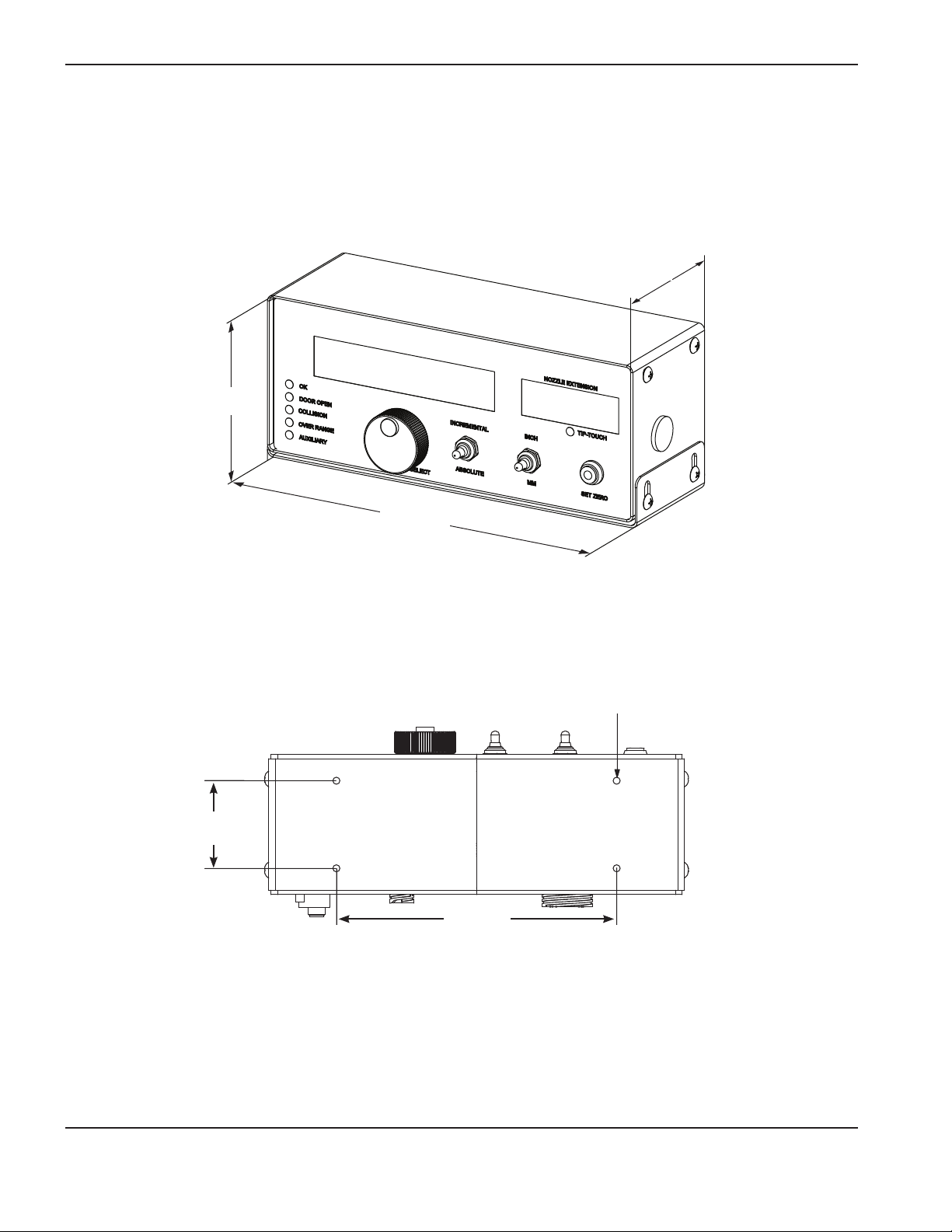
SpecificationS
Laser head controller – 051026
Overview
The laser head controller includes a liquid crystal display (LCD), operating switches, and a rotary/push knob selector for
laser setup and control.
130.50 mm
5.14 in
117.60 mm
4.63 in
63.5 mm
(2.5 in)
298.40 mm
11.75 in
Diameter
5.0 mm (0.20 in)
4places
203.2 mm
(8.0 in)
Laser head controller mounting bracket dimensions
1-14 HyIntensity Fiber Laser Instruction Manual – 807090 Revision 3
Page 47

SpecificationS
CNC Requirements
Hypertherm CNC
AC input power
100-240 VAC 50/60 Hz
CNC
EDGE Pro CNC or MicroEDGE Pro with Integrated Sensor THC interface
Z axis lifter
Hypertherm Sensor THC
CNC I/O Interface
All of the CNC I/O signals are communicated over Hypernet to the fiber laser cable connector through a standard
Hypernet port
HyIntensity Fiber Laser Instruction Manual – 807090 Revision 3 1-15
Page 48

SpecificationS
Generic CNC
Z axis lifter
• Modified to allow mounting of fiber laser head bracket
• Capable of moving fiber laser head (7.8 kg / 17.2 lbs)
CNC I/O interface
Physical connectors: Phoenix contact part numbers 1772405 and 1772418
CNC digital outputs (0-24 VDC sourcing opto-isolators from CNC to laser controller, 24 VDC = active [on])
Fault acknowledge/reset (rising edge triggered) ..........................................................Required
Digital beam ........................................................................................................................... Required
Pointing laser enable ...........................................................................................................Required
Corner power pulsing enable ............................................................................................Optional
Side jet ....................................................................................................................................Optional
Air select (off = O2, on = air) ............................................................................................Required
N2 select .................................................................................................................................Required
CNC digital inputs (Normally Open [NO] isolated 24 VDC relay contacts from laser controller to the CNC)
Laser fault ...............................................................................................................................Required
Pointing laser status ............................................................................................................Optional
Laser head fault ....................................................................................................................Required
Nozzle contact ....................................................................................................................... Required
Over range (>10 mm) ..........................................................................................................Optional
Gas control fault ...................................................................................................................Required
CNC analog outputs to laser controller (0 – 10 VDC)
Laser power set point (0 – maximum output power in watts) ....................................Required
Corner power (duty cycle) set point (1 – 99%) ............................................................ Optional
Assist gas pressure set point ............................................................................................Required
(Air/O2 = 0 – 130 psi, N2 = 0 – 500 psi)
CNC analog input from laser controller (0 – 10 VDC)
Capacitive height sensor voltage (scaling 1 volt per mm) .......................................... Required for auto height control
1-16 HyIntensity Fiber Laser Instruction Manual – 807090 Revision 3
Page 49

Section 2
INSTALLATION
Upon receipt
• Verify that all system components on your order have been received. Contact your supplier if any items
are missing.
• Inspect the system components for any physical damage that may have occurred during shipping. If there is
evidence of damage, refer to Claims. All communications regarding claims must include the model number and
serial number located on the rear of the power supply.
Claims
Claims for damage during shipment – If your unit was damaged during shipment, you must file a claim with the
carrier. Hypertherm will furnish you with a copy of the bill of lading upon request. If you need additional assistance, call
Customer Service listed in the front of this manual, or your authorized Hypertherm distributor.
Claims for defective or missing merchandise – If any of the merchandise is defective or missing, contact your
supplier. If you need additional assistance, call Customer Service listed in the front of this manual, or your authorized
Hypertherm distributor.
HyIntensity Fiber Laser Instruction Manual – 807090 Revision 3 2-1
Page 50

InstallatIon
Installation requirements
All installation and service of the electrical and plumbing systems must conform to national and local
electrical and plumbing codes. This work should be performed only by qualified, licensed personnel.
Direct any technical questions to the nearest Hypertherm Technical Service Department listed in the front of this manual,
or your authorized Hypertherm distributor.
Noise levels
Acceptable noise levels as defined by national and local codes may be exceeded by this laser system. Always wear
proper ear protection when cutting. Any noise measurements taken are dependant on the specific environment in which
the system is used. See also Noise can damage hearing in the Safety section of this manual. Specific information by
product can be found in the Hypertherm downloads library at:
https://www.hypertherm.com/Xnet/library/DocumentLibrary.jsp
Select the product you are looking for from the Product Type drop down menu, choose “Regulatory” from the Category
drop down menu, and choose “Acoustical Noise Data Sheets” from the Sub Category drop down menu. Hit Submit.
Placement of system components
• Place all system components in position prior to making electrical, gas, and interface connections. Use the
diagram in this section for component-placement guidelines.
• Ground all system components to earth. See Recommended grounding and shielding practices in this section
for details.
• To prevent leaks in the system, tighten all gas and water connections as shown below:
Torque specifications
Gas or water
hosesize kgf – cm lbf – in lbf – ft
Up to 10 mm (3/8 in) 8.6 – 9.8 75 – 85 6.25 – 7
12 mm (1/2 in) 41.5 – 55 360 – 480 30 – 40
2-2 HyIntensity Fiber Laser Instruction Manual – 807090 Revision 3
Page 51

InstallatIon
Site preparation before startup
Before beginning laser welding or cutting operations, all connections to the final laser cutting system shall be checked
to make certain they are properly made in accordance with the laser cutting system instructions and local regulations.
• All indicator and warning lights shall be checked.
• Signage shall be posted to give adequate warning.
• Shielding shall be in place at all times to capture and stop any errant beams.
• A lockable disconnect switch may need to be provided in the electrical wiring to the component fiber laser
power supply and locked out when not in use. The emergency stop circuit with a red emergency stop actuator
with a yellow background is also provided.
• All doors and panels which prevent access to the laser beam in the final laser cutting system and control
panels, accessible at the production floor level, shall be tested for proper shutdown before startup and kept
locked or interlocked to prevent access by unauthorized people.
• A door to access panels shall be considered locked if a key, wrench, or other tool is required to open it.
Aperiodic functional test of safety interlocks for proper shutdown shall be made by the laser safety officer
inaccordance with local regulations and the final laser cutting system instructions.
HyIntensity Fiber Laser Instruction Manual – 807090 Revision 3 2-3
Page 52

InstallatIon
1
8
F
2
3
4
5
6
7
11
9
Installation requirements
D
10
A
10
E
B
12
13
C
Coolant hoses
Electrical
Gas hoses
Beam delivery optical
cable (BDO)
System diagram using a Hypertherm CNC
2-4 HyIntensity Fiber Laser Instruction Manual – 807090 Revision 3
Page 53

System components
F
1
2
3
4
5
6
7
8
9
Fiber laser supply
A
Laser head controller
B
Gas control console
C
Chiller (customer supplied)
D
Laser head
E
CNC (customer supplied)
Lifter (not shown, customer supplied)
G
Cables and hoses
Beam delivery optical cable (Beam delivery optical cable)
InstallatIon
Coolant hoses: fiber laser supply to the laser head
Coolant hoses: fiber laser supply to the chiller (customer supplied)
Hi-flex Hypernet cable: fiber laser supply to CNC (for use with the EdgePro or MicroEDGE Pro)
Hi-flex Hypernet cable: fiber laser supply to laser head controller
Gas control cable: gas control console to laser head controller
I/O cable: laser head controller to laser head
Gas hoses: gas control console to laser head
Power cable: laser head controller* (customer supplied)
Power cables (customer-supplied)
10
Main power cables
Supply gas hoses (customer supplied)
Oxygen
11
12
Nitrogen
13
Air
* Kit 228629 includes sockets and backshell
HyIntensity Fiber Laser Instruction Manual – 807090 Revision 3 2-5
Page 54

InstallatIon
Recommended grounding and shielding practices
DANGER
ELECTRIC SHOCK CAN KILL
Disconnect electrical power before performing any maintenance. All work
requiring the removal of the power supply cover must be performed by a
qualified technician.
See Section 1 of the laser/plasma system instruction manual for more safety
precautions.
Introduction
This document describes the grounding and shielding necessary to protect a laser/plasma cutting system installation
against radio frequency interference (RFI) and electromagnetic interference (EMI) noise. It addresses the three
grounding systems described below. There is a diagram on page 3-10 for reference.
Note: These procedures and practices are not known to succeed in every case to eliminate RFI/EMI noise
issues. The practices listed here have been used on many installations with excellent results, and we
recommend that these practices be a routine part of the installation process. Theactual methods used to
implement these practices may vary from system to system, but should remain as consistent as possible
across the product line.
Types of grounding
A. The safety (PE) or service ground. This is the grounding system that applies to the incoming line voltage. It
prevents a shock hazard to any personnel from any of the equipment, or the work table. It includes the service
ground coming into the laser/plasma power supply and other systems such as the CNC controller and the
motor drivers, as well as the supplemental ground rod connected to the work table. In the laser/plasma circuits,
the ground is carried from the laser/plasma power supply chassis to the chassis of each separate console
through the interconnecting cables.
B. RFI and EMI grounding and shielding. This is the grounding system that limits the amount of electrical “noise”
emitted by the laser/plasma and motor drive systems. It also limits the amount of noise that is received by the
CNC and other control and measurement circuits. This grounding/shielding process is the main target of this
document.
2-6 HyIntensity Fiber Laser Instruction Manual – 807090 Revision 3
Page 55

InstallatIon
Steps to take
1. Unless noted, use only 6 AWG (16 mm2) welding cable (Hypertherm part no. 047040) for the EMI ground
cables shown on the diagram.
2. The cutting table is used for the common, or star, EMI ground point and should have threaded studs welded
to the table with a copper bus bar mounted on them. A separate bus bar should be mounted on the gantry as
close to each drive motor as possible. If there are drive motors at each end of the gantry, run a separate EMI
ground cable from the far drive motor to the gantry bus bar. The gantry bus bar should have a separate, heavy
EMI ground cable (4 AWG [21.2 mm2] part no. 047031) to the table bus bar. The EMI ground cables for the
torch lifter and the RHF console must each run separately to the table ground bus.
3. A ground rod that meets all applicable local and national electrical codes must be installed within 6 m (20 ft)
of thetable. This is a PE ground and should be connected to the ground bus on the cutting table with 6 AWG
(16mm2) green/yellow grounding cable (Hypertherm part number 047121) or equivalent. All PE grounds are
shown on the diagram in green.
4. For the most effective shielding, use the Hypertherm CNC interface cables for I/O signals, serial communication
signals, power supply-to-power supply multi-drop connections, and interconnections between all parts of the
Hypertherm system.
5. All hardware used in the ground system must be brass or copper. The only exception is that the studs welded
to the table for mounting the ground bus can be steel. Under no circumstances should aluminum or steel
hardware be used.
6. AC power, PE, and service grounds must be connected to all equipment according to local and nationalcodes.
7. Each Hypertherm component, as well as any other CNC or motor-drive cabinet or enclosure, must have a
separate ground cable to the common (star) point on the table. This includes the ignition console, even if it is
bolted to the power supply or to the cutting machine.
8. The laser head holder and the breakaway mechanism – the part mounted to the lifter, not the part mounted on
thetorch – must be connected to the stationary part of the lifter with copper braid at least 12.7 mm (1/2 in)
wide. Aseparate cable must run from the lifter to the bus bar on the gantry. The valve assembly should also
have a separate ground connection to the gantry bus bar.
9. If the gantry runs on rails that are not welded to the table, then the rails need to be connected with a ground
cable from each end of both rails to the table. These need not go to the common (star) point, but could take the
shortest path to the table.
10. All other signals (analog, digital, serial, encoder) should run in twisted pairs inside a shielded cable. Connectors
on these cables should have a metal housing and the shield, not the drain, should be connected to the metal
housing of the connectors at each end of the cable. Never run the shield or the drain through the connector on
any of the pins.
HyIntensity Fiber Laser Instruction Manual – 807090 Revision 3 2-7
Page 56
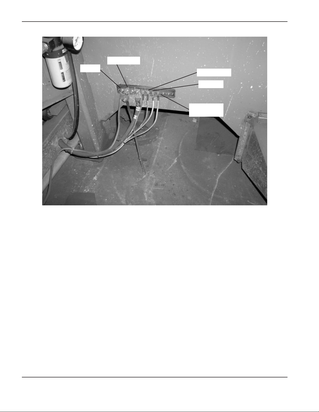
InstallatIon
Ground rod
Gantry
CNC enclosure
Laser head
Power supply
chassis
Example of a good cutting table ground bus. The picture above shows the connection from the
gantry ground bus, the connection from the ground rod, the CNC enclosure, the laser head, and
thefiber laser supply chassis.
2-8 HyIntensity Fiber Laser Instruction Manual – 807090 Revision 3
Page 57

InstallatIon
Cable to ground bus
onthe cutting table
Component
ground cables
Example of a good gantry ground bus. It is bolted to the gantry, close to the motor. All of the individual
ground cables from the components mounted on the gantry go to the bus. A single heavy cable then
goes from the gantry ground bus to the ground bus bolted to the table.
HyIntensity Fiber Laser Instruction Manual – 807090 Revision 3 2-9
Page 58

InstallatIon
CNC
console
Chiller
Cutting table
Gas
console
controler
Laser head
head
Laser
THC
Sensor
Bus bar
supply
Fiber laser
Gantry
AC earth/service ground Chassis and RFI ground
Grounding diagram (some systems will not include all the components shown)
2-10 HyIntensity Fiber Laser Instruction Manual – 807090 Revision 3
Page 59

InstallatIon
A
Placement of the fiber laser supply
DANGER
ELECTRICAL SHOCK CAN KILL
Remove all electrical connections to the laser power supply before moving or positioning.
Transporting the fiber laser supply can cause personal injury and equipment damage.
The fiber laser supply can be moved by forklift but the forks must be long enough to extend the entire length of the base.
Take care when lifting so that the underside of the fiber laser supply, and the drain that comes through the underside of
the fiber laser supply (HFL010, HFL015, and HFL020 only), are not damaged.
• Place the fiber laser supply in an area that is free of excessive moisture, has proper ventilation, and is relatively
clean. Allow 1 m (3 ft) on all sides of the fiber laser supply for servicing.
• Do not place the power supply on an incline greater than 10° to prevent it from toppling.
Note: The graphic below shows the enclosure for the HFL010, HFL015, and HFL020
The drain is located on the
underside of the enclosure
at this corner.
HyIntensity Fiber Laser Instruction Manual – 807090 Revision 3 2-11
Page 60

InstallatIon
Lifting the fiber laser supply
DANGER
The fiber laser supply weighs between 185 kg and 283.5 kg (410 lbs and 625 lbs). 1 or 2 person
manual lifting could cause injury. Use appropriate lifting aids and techniques when moving a fiber
laser supply.
The customer understands and assumes exclusive responsibility for supplying personnel trained and qualified to operate
forklifts, cranes, hoists and other lifting devices to lift or move the fiber laser. All movement of the fiber laser supply must
be done in compliance with applicable local laws and regulations. All handling equipment must be evaluated for each
application and inspected and tested before each use. The fiber laser supply can be moved by forklift, but the forks must
be long enough to extend the entire length of the base. Take care when lifting so that the underside of the fiber laser
supply is not damaged. The customer agrees to observe and ensure compliance with the following:
• The straps and other handling equipment must comply with applicable local standards, laws and regulations.
• The rated capacity, design factor, and efficiency rating of the lifting system, including straps sold by Hypertherm,
may be affected by wear, misuse, overloading, corrosion, deformation, intentional alteration, age, and other use
conditions.
• An inspection of the straps by qualified personnel should be conducted before each use. Worn or damaged
straps may not be used, nor may they be altered or modified in any way.
• All 4 loops at the ends of the straps must be securely and properly attached to the lifting mechanism.
• The fiber laser supply is a nonsymmetrical load; make sure that an analysis by a qualified person is performed
properly to balance the load to prevent tipping and overloading of any one strap.
• All enclosure panels must be securely fastened before lifting the fiber laser supply.
• The lifting mechanism must be rated for the appropriate weight and be suitable for the strap size.
• Each strap should pass through all 4 lifting eyelets in the top of the fiber laser supply and should not be twisted,
constricted, bunched or pinched.
• Straps shall not be shortened or lengthened by knotting, twisting, choker hitching, or other means.
• The fiber laser supply should be lifted slowly, not more than 203 mm (8 in) above the floor, to insure that the
weight is evenly distributed.
• The fiber laser supply should be moved slowly to prevent sudden acceleration and deceleration when moving.
• Access to the area should be restricted when moving or lifting to prevent injury of personnel if the fiber laser
supply shifts or tips.
• Personnel should never be allowed to place themselves or any part of the body under the equipment, or
between the equipment and walls or other solid objects.
2-12 HyIntensity Fiber Laser Instruction Manual – 807090 Revision 3
Page 61
InstallatIon
• Store straps in a proper manner such that they are not subjected to mechanical, chemical, or ultraviolet damage,
or to extreme temperatures.
The body responsible for the workplace where the equipment is to be installed needs to make sure all applicable local
regulations are followed, and Hypertherm assumes no responsibility or liability therefor. The customer assumes exclusive
responsibility for ensuring that all local laws and regulations are followed, including those applicable to the use of
equipment and work place conditions.
WARNING
• Operation and maintenance of automated equipment involves potential hazards.
• Only authorized service personnel should perform this service.
• REMOVE ALL POWER TO THE FIBER LASER SUPPLY ENCLOSURE BEFORE BEGINNING
PROCEDURE.
• Warning undesired results may occur if these instructions are not followed exactly in order
without skipping any steps
Fiber laser supply preparation
General information
The installations on the following pages should be performed before making any other connections to the fiber laser
supply.
HyIntensity Fiber Laser Instruction Manual – 807090 Revision 3 2-13
Page 62

InstallatIon
Emergency stop (E-Stop) switch installation
1. Open the fiber laser supply enclosure front door and
locate the E-Stop switch assembly.
E-Stop switch assembly location
2. Remove the actuation knob and lock-nut from the
E-Stop switch assembly.
Press and twist the knurled area
Lock nut
3. Place the actuation knob into the “EMERGENCY
STOP” mounting hole on the top of the fiber
laser supply enclosure, and use the lock nut to
secure the E-stop actuation knob to the top of the
enclosure.
Actuation knob Lock nut Switch
Emergency stop mounting hole
4. Align the switch’s contact base thumb ring with the
arrow on the actuation knob and press.
2-14 HyIntensity Fiber Laser Instruction Manual – 807090 Revision 3
Page 63
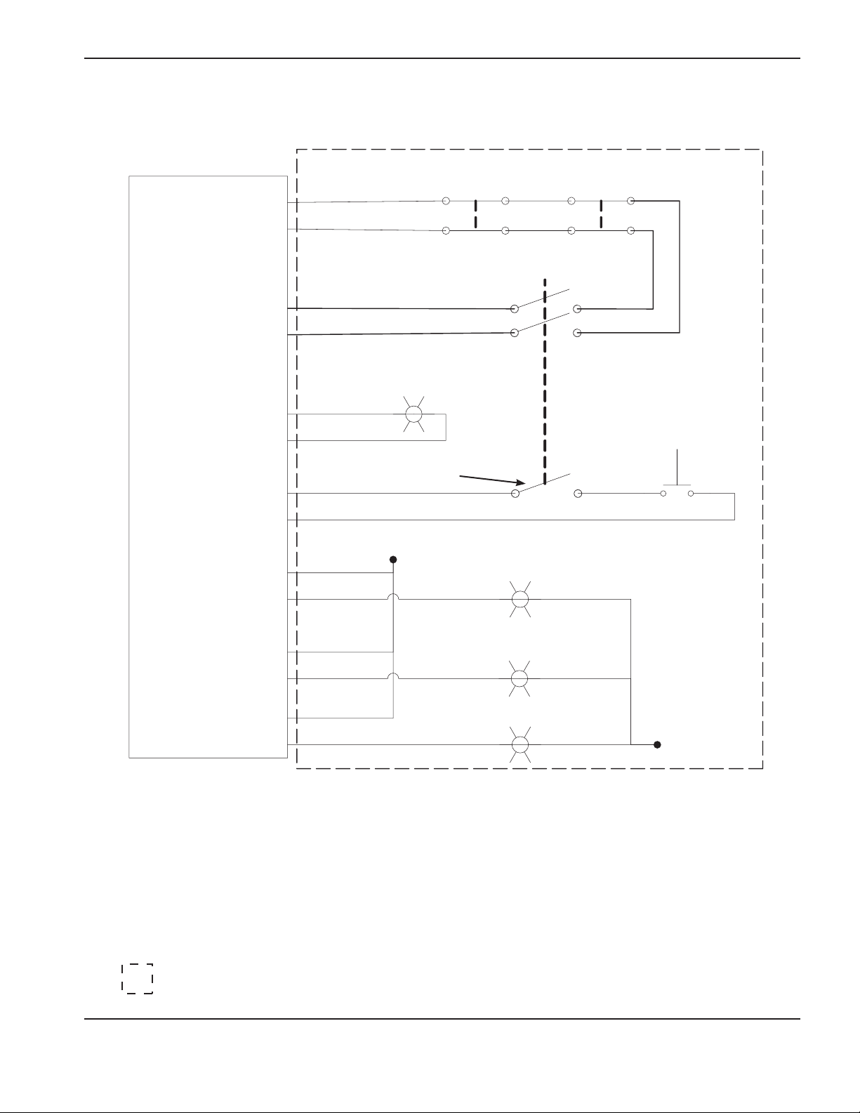
Electrical diagram for external safety switches
InstallatIon
LPC2
A-1
A-2
C-2
C-1
A-3
C-3
A-4
C-4
A-7
C-7
Start/Reset
Switch Indicator
Key Switch
+24 VDC
External Door
Interlock External E-Stop
Key Switch (optional contacts)
Red Stack Light
(supplied by user and machine
mounted)
Start/Reset
Momentary Switch
A-6
Yellow Stack Light
C-6
A-5
Green Stack Light
C-5
Recommended components:
E-Stop switch – Rockwell Automation part numbers 800FP-LMT44, 800F-PN3R, and (2) 800F-X01
Start/Reset switch – Rockwell Automation part numbers 800FP-LF3, 800F-PN3G, and 800F-X01
Key switch – Rockwell Automation part numbers 800FP-KM21 and 800F-X10
Stack light – Rockwell Automation part numbers 855D-P00SC20B24Y3Y5L4
= Customer supplied components
HyIntensity Fiber Laser Instruction Manual – 807090 Revision 3 2-15
Page 64

InstallatIon
Stack Light installation
1. Open the rear door of the fiber laser supply enclosure and
locate the cardboard box on the bottom left below the power
interconnect panel.
2. Remove the stack light, gasket and mounting hardware from the
cardboard box.
3. Mount the stack light to the top of the enclosure, at the location
shown, using the hardware included.
4. Connect the plug on the end of the yellow cable from the stack
light to the socket located directly above the incoming power
disconnect switch.
Stack light mounting location
Socket
Plug
Stack light color descriptions
Red flashing = Laser is on. All safety precautions must be followed.
Yellow = The laser may come on at any time. All safety precautions must
befollowed.
Green = Safe
2-16 HyIntensity Fiber Laser Instruction Manual – 807090 Revision 3
Page 65

InstallatIon
Dehumidifier drain installation
Note: This procedure does not need to be perfomed if you have an HFL030 system
1. Open the rear door of the fiber laser supply enclosure and locate the dehumidifier drain assembly that is
secured to the enclosure frame with a cable tie. Cut the cable tie and remove the hose from the drain assembly.
Barbed brass fitting
1 in. hex nut
Drain
Hose and drain assembly location
Drain assembly parts
2. Remove the small rubber plug from the hole in the bottom of the fiber laser supply enclosure.
Rubber plug
Plug location
HyIntensity Fiber Laser Instruction Manual – 807090 Revision 3 2-17
Page 66

InstallatIon
3. Insert the threaded end of the drain through the hole in the bottom of the laser supply enclosure from
underneath the enclosure and secure it with the 1 in hex nut. Tighten the nut just enough to compress the black
gasket using a 1 in. open end wrench.
Install drain
4. Fasten the barbed brass fitting onto the end of the drain device. DO NOT OVERTIGHTEN!
Install brass fitting
5. Push the drain hose onto the barbed fitting to complete the assembly procedure.
Install drain hose
2-18 HyIntensity Fiber Laser Instruction Manual – 807090 Revision 3
Page 67

InstallatIon
Mounting the laser head controller (LHC)
B
The mounting brackets on the LHC allow for a variety of mounting options. It can be installed under or on another piece
of equipment, and level or tilted. The LHC should be mounted in a location on the gantry that allows the operator to see
the display when changing the nozzle extension on the laser head and during cutting.
LHC mounted on a surface
and tilted up.
LHC mounted on a surface
and tilted down.
Diameter
5.0 mm (0.20 in)
4places
63.5 mm
(2.5 in)
203.2 mm
(2.5 in)
Laser head controller mounting bracket dimensions
Laser head controller grounding
HyIntensity Fiber Laser Instruction Manual – 807090 Revision 3 2-19
Page 68
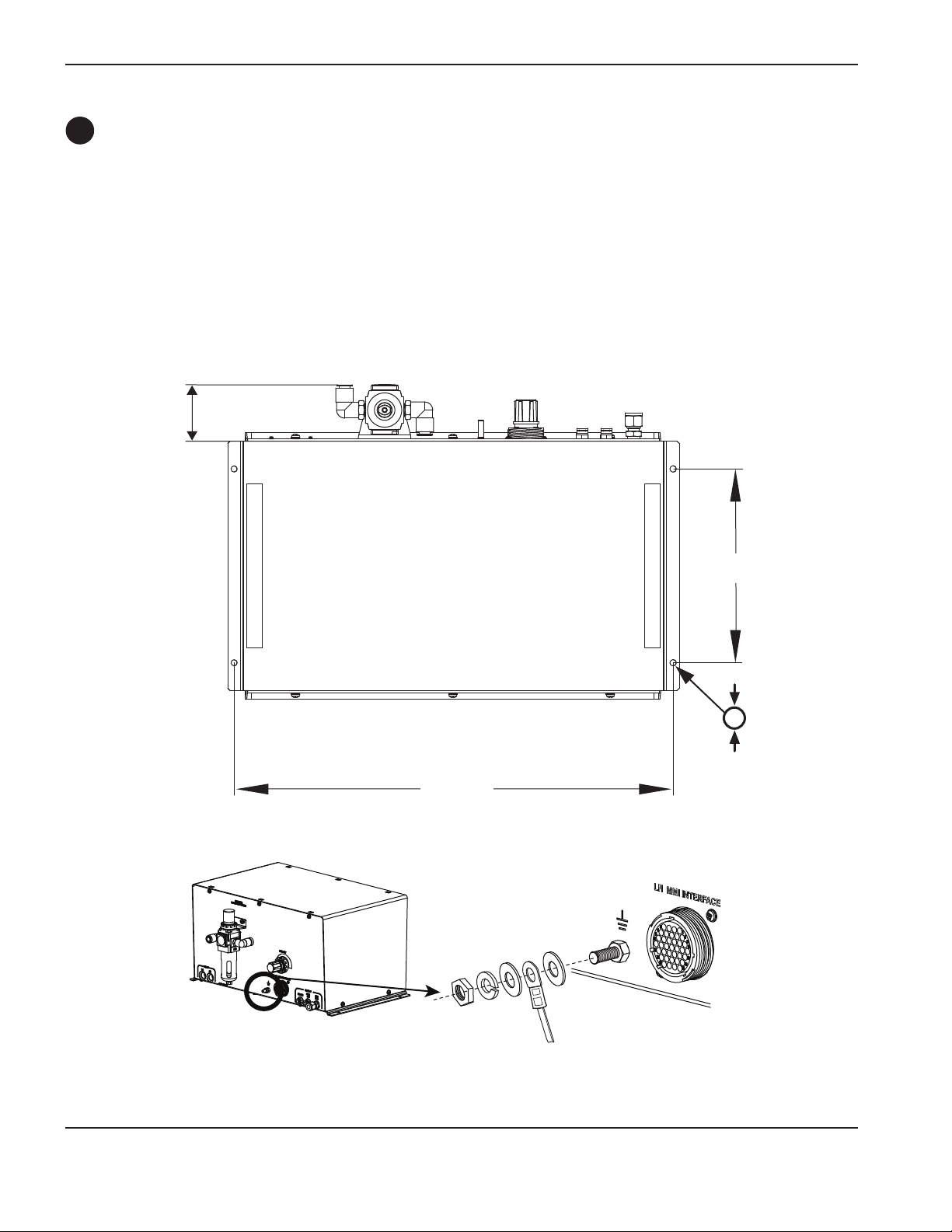
InstallatIon
C
Mounting the gas console
The gas console is usually mounted on the gantry to allow visibility to the operator. Additionally, the cutting gas supply
line between the console and laser head should be kept as short as possible to reduce pressure loss with a maximum
hose length of 10 m (30 ft). The supply lines to the gas console must be sized appropriately to support the required
pressures and flow rates for each gas.
The gas console for the laser cutting process is designed to cover the normal operating parameters for the assist
gas needed for laser cutting of mild steel, stainless steel, and aluminum. Additional outputs from the gas console are
provided for cooling of the laser head and a side jet for piercing of thicker materials. A supply of oxygen, nitrogen, and air
is required for proper operation, and the requirements are outlined in the Specifications section. To achieve the required
dynamic assist gas pressure performance for laser cutting, the maximum length of hose between the gas console and
the laser head is 10 m (30 ft). Use the 10 m (30 ft) hose (024874) supplied with this system.
63.5 mm
2.5 in
460.375 mm
18.125 in
203.2 mm
8.0 in
6.731 mm
0.265 in
(4 places)
Gas console grounding
2-20 HyIntensity Fiber Laser Instruction Manual – 807090 Revision 3
Page 69

InstallatIon
D
Chiller considerations
Caution: The cooling system must have a filter that allows the coolant to meet the
specifications for particles shown below. Failure to use a filter capable of meeting the
particle requirements can cause damage to critical optical components and could be
cause for denial of warranty claims on these components.
• The chiller is supplied by the customer and must meet the minimum requirements as stated in the Specifications
section of this manual.
• The chiller should be placed close to the fiber laser supply.
• Delivery lines should be sized to prevent excessive pressure drops along the lines. 20 mm (3/4 in) inside
diameter or larger is recommended for line lengths less than 10 m (30 ft). Longer lengths may require hoses
with a larger diameter.
• Prevent unexpected kinking, pinching, or other restrictions in the supply and return lines.
• Coolant lines should be protected from abrasion or punctures.
• Place the chiller in an area that is free of excessive moisture, has proper ventilation, and is relatively clean.
Allow1 m (3 ft) of space on all sides of the chiller for ventilation and service.
• Do not place the chiller on an incline greater than 10° (with the wheels locked) to prevent it from toppling.
• Use reinforced Tygon, copper, stainless steel or PVC, for the plumbing. Use sizes appropriate to achieve the
necessary flow rates.
• Refer to the manual that came with your chiller for operation and maintenance information.
HyIntensity Fiber Laser Instruction Manual – 807090 Revision 3 2-21
Page 70

InstallatIon
E
Mounting the laser head
Install the laser head mounting bracket
The laser head is shipped with a plastic cap covering the main opening. To protect the optics inside the laser head, the
cap must remain in place unless you are told to remove it.
Plastic cap
Briefly remove the plastic cap from the laser head and Install the laser head mounting bracket onto the laser head
using the 3 bolts provided. Immediately cover the hole in the laser head mounting bracket with the plastic cap after the
mounting bracket is installed.
Plastic cap
Laser head
mounting bracket
2-22 HyIntensity Fiber Laser Instruction Manual – 807090 Revision 3
Page 71

InstallatIon
Laser head grounding
The laser head and mounting bracket must be properly earth grounded for stable operation. An M6 x 1 thread is
provided on the side of the mounting bracket to connect an earth ground wire that should be tied to the machine
earthground.
Mounting bracket
Laser head mounting dimensions
57.2 mm
2.25 in
Ground connection
171.5 mm
6.75 in
152.4 mm
6.00 in
31.5 mm
1.24 in
Diameter
108.0 mm
4.25 in
Top view
HyIntensity Fiber Laser Instruction Manual – 807090 Revision 3 2-23
Page 72

InstallatIon
Diameter 6.6 mm (0.26 in) through hole (4 places)
Diameter 11.0 mm (0.43 in) counterbore
Diameter 6.8 mm (0.27 in) through hole (4 places)
Diameter 11.1 mm (0.44 in) counterbore
101.6 mm
4.0 in
269.8 mm
10.62 in
Full extension
Front view
Diameter 3.0 mm
(0.118 in)
(2 places)
45.0 mm
1.77 in
90.0 mm
3.54 in
32.0 mm
1.26 in
36.0 mm
1.42 in
50.0 mm
1.97 in
62.7 mm
2.47 in
Rear view
2-24 HyIntensity Fiber Laser Instruction Manual – 807090 Revision 3
Page 73

InstallatIon
1
Beam delivery optical cable connection
The optical power from the fiber laser supply is delivered through the beam delivery optical cable/optics. Because of the
small surface area and the high power levels, cleanliness of the input and output optical surfaces is critical to component
lifetime and proper operation. The optical surface at the bayonet end of the Beam delivery optical cable should be
inspected, with the magnifier that was supplied with the system, before installation and whenever it is removed from the
collimator. To prevent contamination and chipping, the optical surface should not be touched. See page 4-4 for details
of the inspection and cleaning procedure.
Caution: The minimum bend radius of the Beam delivery optical cable is 100mm
(4 in). The fiber can be damaged if the radius is anysmaller.
100 mm
(4 in)
100 mm
(4 in)
200 mm
(8 in)
Diameter = 2 x radius = 200 mm (8 in)
Beam delivery optical cable part numbers
Part number Length
051029 10 m (33 ft) 100 micron
051030 20 m (65.5 ft) 100 micron
051045 20 m (65.5 ft) 200 micron
HyIntensity Fiber Laser Instruction Manual – 807090 Revision 3 2-25
Page 74

InstallatIon
General Precautions
The Beam delivery optical cable is placed in a protective foam tray on top of the fiber laser supply enclosure for
shipping. This cable is rugged and flexible, but it must be unpacked and handled carefully to prevent damage to the
delicate optical fiber inside.
The following precautions are recommended at all times:
• Do not remove the black protective cap from the end of the Beam delivery optical cable until instructed to do so
later in these instructions
• At least two people should be involved in handling the Beam delivery optical cable.
• The cable exits the fiber laser supply enclosure at the top through a strain relief block; do not attempt to push or
pull the cable at this point.
• The end of the beam delivery optical cable that attaches to the laser head is the “fiber bayonet”; when not
attached to the laser head, this end should have the protective cap installed and be supported by hand at all
times. Do not allow it to swing freely while handling the beam delivery optical cable as this component is heavy
and can cause the flexible cable to bend sharply and damage the optical fiber.
• Do not exceed the minimum short-term bend radius of the cable, 100 mm (4 in).
Unpacking Instructions
1. Carefully lift the entire coil of the beam delivery optical
cable out of and above the foam tray and slide the
tray out from under the beam delivery optical cable.
If the beam delivery optical cable enters the tray
through a hole instead of a slot, it will be necessary to
carefully uncoil the entire length of the beam delivery
optical cable in order to remove the foam tray. See
instructions in steps 3 and 4 for uncoiling the beam
delivery optical cable.
2. Place the beam delivery optical cable back on top
of the fiber laser supply enclosure inside the four
retaining brackets as shown in the picture to the right.
3. Uncoil the desired length of beam delivery optical
cable one loop at a time.
4. As each loop is uncoiled, make sure to relieve torsion in the beam delivery optical cable; if residual torsion is
allowed to build up, the beam delivery optical cable may twist unexpectedly. Usually, torsion can be relieved by
twisting the free end ofthe beam delivery optical cable 360 degrees for each loop uncoiled from the bundle.
5. For temporary, overhead installation of the beam delivery optical cable, support it every 1-2 m (3.3-6.6 feet)
6. Attach the beam delivery optical cable to the collimator at the laser head according to the beam delivery optical
cable installation instructions in this section.
7. Carefully inspect the entire beam delivery optical cable to ensure that all bends are maintained at a radius
greater than 100mm (4 in).
2-26 HyIntensity Fiber Laser Instruction Manual – 807090 Revision 3
Page 75

InstallatIon
Beam delivery optical cable installation
WARNING
• Operation and maintenance of automated equipment involves potential hazards.
• Only authorized service personnel should perform this service.
• REMOVE ALL POWER TO THE FIBER LASER SUPPLY ENCLOSURE BEFORE BEGINNING
PROCEDURE.
• Undesired results may occur if these instructions are not followed exactly in order, or if any
steps are notcompleted.
1. Carefully route the beam delivery optical cable from the fiber laser supply enclosure through the protective
cable trays of the machine frame to the laser head.
Note 1: Sometimes it is not possible to rotate the bayonet on the beam delivery optical cable to align the red
dots on thecollimator and the bayonet, after it has been routed to the laser head, without creating
excessive torsional tension on the cable. In this case remove the 3 Allen head cap screws that attach
the laser head adaptor to the laser head mounting bracket. Then rotate the collimator so that the red
dots can be aligned without putting excessive twist to the delivery fiber and reinstall the 3 Allen head
cap screws. The laser head adaptor can be rotated in 120 degree increments to relieve excess torsion
on the beam delivery optical cable.
2. Inspect the entire path of the beam delivery optical cable and verify that the minimum bend radius specification
of 100 mm (4 in). is not violated and that there are no pinch points that could damage the Beam delivery optical
cable during machine motion.
3. Verify that there is enough length in the beam delivery optical cable at the Laser Head to allow for the motion of
the lifter axis while raising and lowering the laser cutting head
4. Temporarily secure the end of the beam delivery optical cable near the laser head until it is time to connect it to
the collimator.
Note Do not remove the black protective cap from the end of the
beam delivery optical cable until instructed to do so later in these
instructions
HyIntensity Fiber Laser Instruction Manual – 807090 Revision 3 2-27
Page 76

InstallatIon
Collimator installation
The collimator is a precision optical device that aligns the diverging beam from the Beam delivery optical cable into a
parallel or collimated beam.
WARNING
Remove all power to the fiber laser supply enclosure before beginning the installation.
Caution: Any dust, debris, or moisture inside the collimator can cause damage
tothe equipment. Be extremely careful to avoid any contamination.
Caution: Remove the focusing lens in the laser head before installing the
collimator to prevent any debris from falling onto the lens. Any debris
on the lens can cause damage.
General precautions
• DO NOT remove the collimator from its original packaging until instructed to do so later in this document.
• DO NOT remove the clear protective cap (shown below) from the input end of the collimator until instructed to
do so later in these instructions.
• DO NOT remove the black protective cap (shown below) from the output end of the collimator until instructed
to do so later in these instructions.
Colimator input
protective cap
Colimator output
protective cap
2-28 HyIntensity Fiber Laser Instruction Manual – 807090 Revision 3
Page 77
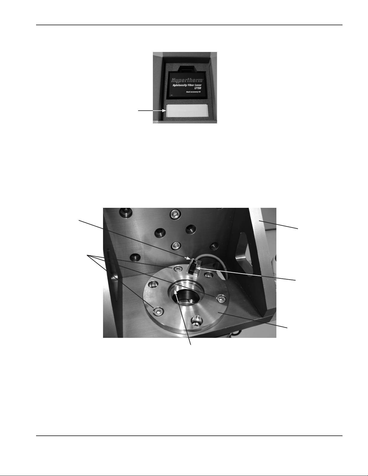
The collimator is shipped in the same box as the LF150 laser head and the head accessory kit
Collimator
1. Remove the Proximity sensor before installing the collimator.
a. Verify that the the focusing lens is not installed in the laser head
b. Remove the collimator proximity sensor from the laser head adaptor flange by loosening the mounting bolt
with a 2.5mm hex wrench and then sliding the proximity sensor out from under it. Refer to the picture
below for the location of the proximity sensor and mounting bolt. Retighten the proximity sensor mounting
bolt after removing the proximity sensor.Remove the laser head adaptor flange from the laser head
mounting bracket by removing the three adaptor flange mounting bolts (shown above).
InstallatIon
Proximity sensor
mounting bolt
Adaptor flange
mounting bolts
Center hole threads
Laser head
mounting bracket
Proximity sensor
Laser head
adaptor flange
2. Inspect the threads in the center hole of the laser head adaptor flange for any dirt or debris and clean them if
necessary.
3. Remove the collimator from the original packaging.
4. Inspect the outside of the collimator for any dust or debris before proceeding. If any dust or debris is present,
use clean dry compressed air or a lens cleaning tissue to remove it.
HyIntensity Fiber Laser Instruction Manual – 807090 Revision 3 2-29
Page 78
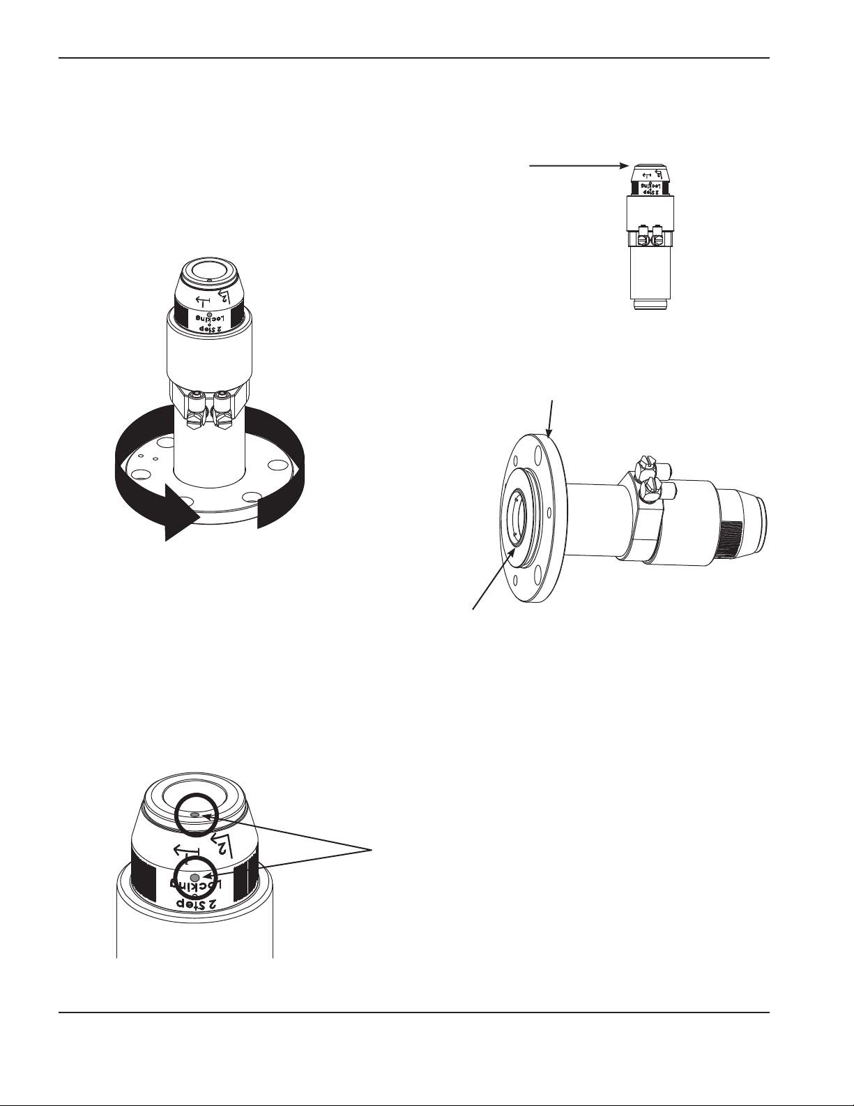
InstallatIon
5. Carefully remove the protective caps from both ends of the collimator and inspect the inside of the collimator for
any dust, debris, or filmy residue. If any dust, debris, or residue is present the collimator must be inspected and
cleaned by properly trained personnel before use.
6. Reinstall the clear protective cap onto the input end of the colimator.
7. Hold the collimator in a vertical position with the clear protective cap
pointing up and carefully install the laser head adaptor flange onto
the collimator by threading it onto the collimator as shown below.
Turn the adaptor flange by hand until tight.
Laser head adaptor flange
Collimator threads
Note 1: When the flange is properly installed onto the collimator the threads on the collimator extend slightly
beyond the bottom of the flange. See the figure above.
8. Verify that the locking ring on the top of collimator is in the unlocked position. The locking ring is in the unlocked
position when the red dots are aligned.
Red dots
2-30 HyIntensity Fiber Laser Instruction Manual – 807090 Revision 3
Page 79
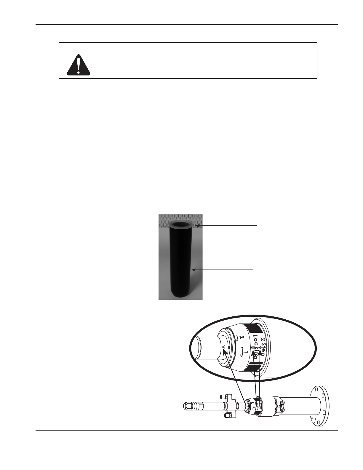
InstallatIon
Caution: Lint and powder free gloves must be worn for the remainder of this
procedure to prevent damage to optical surfaces
9. Put on lint and powder free gloves for the remainder of this procedure.
10. Visually inspect the outside of the bayonet connector on the Beam delivery optical cable for any dust or debris
before proceeding. If any dust or debris exists, use clean dry compressed air or a lens cleaning tissue to remove
it.
11. Carefully remove the black protective cap from the Beam delivery optical cable and visually inspect the quartz
block for any dust, debris or filmy residue. If any dust, debris or filmy residue is present the Beam delivery optical
cable must be cleaned by properly trained personnel before using. Reference the “Cleaning the quartz block”
in the maintenance section of the Fiber Laser Instruction manual for additional information. Reinstall the black
protective cap on the Beam delivery optical cable after inspection or cleaning.
12. With the help of an assistant, hold the bayonet connector of the Beam delivery optical cable in a horizontal
position and carefully remove the black protective cap.
13. With the help of an assistant, hold the collimator in a horizontal position and carefully remove the clear
protective cap from the input end.
14. Insert the clear protective cap into the black protective cap (shown below) and place these into the Head
Accessory kit for future use.
Clear protective cap
Black protective cap
15. Locate the red alignment dots on the bayonet
and the collimator. Rotate the collimator to align
the red dots as shown and carefully insert the
bayonet into the collimator and turn the locking
ring clockwise to lock the devices together.
HyIntensity Fiber Laser Instruction Manual – 807090 Revision 3 2-31
Page 80

InstallatIon
16. Rotate the collimator and laser head adaptor flange assembly to align it to the mounting holes in the laser head
that will minimize the twisting of the Beam delivery optical cable. Install and tighten the three mounting bolts
with a 4mm hex wrench.
2-32 HyIntensity Fiber Laser Instruction Manual – 807090 Revision 3
Page 81

InstallatIon
Collimator proximity sensor
The collimator proximity sensor assembly is mounted on the top of the bracket to ensure the beam is not enabled with
the collimator removed. The sensor is connected to the laser head by a 3 conductor cable.
Note: The collimator should be installed before the proximity switch. The collimator is not shown in the pictures
below for clarity.
1. With the mounting screw slightly loose, insert the “Y” shaped tab under
the screw head.
Proximity sensor
2. With the mounting screw slightly loose, insert the “Y” shaped tab under
the screw head.
3. Align the tab on the proximity sensor bracket with the mounting hole
on the laser head adaptor flange and insert the tab into the hole.
HyIntensity Fiber Laser Instruction Manual – 807090 Revision 3 2-33
Page 82
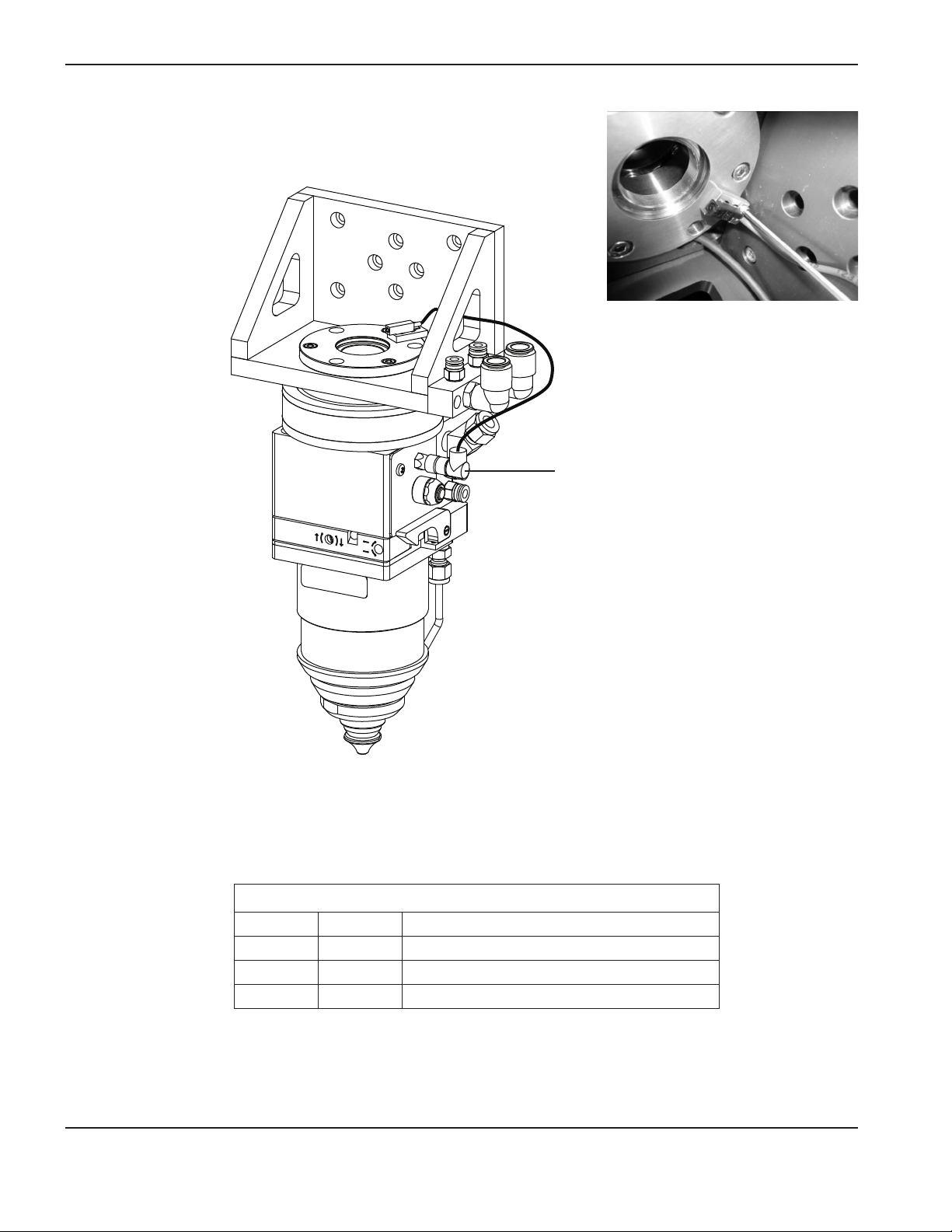
InstallatIon
4. Tighten the mounting screw.
5. Connect the proximity sensor cable to the proximity sensor assembly and to the connector on the side of the
laser head as shown below.
Proximity sensor connector
6. Turn on the power to the system. The orange indicator light on the proximity switch will illuminate if the switch
was installed properly.
Note: The lens holder must be installed in the laser head to power the proximity switch.
Proximity sensor connector pin-outs
Pin Color Signal
1 Brown VDC Common
3 Blue PNP proximity output
4 Black 15 VDC proximity input
2-34 HyIntensity Fiber Laser Instruction Manual – 807090 Revision 3
Page 83

Laser head connectors
InstallatIon
Collimator proximity
connector
Laser head controller
connector
Collimator
Collimator proximity sensor
Coolant return (red)
Coolant supply (blue)
Assist gas
Purge gas
Side jet
HyIntensity Fiber Laser Instruction Manual – 807090 Revision 3 2-35
Page 84

InstallatIon
Coolant hose connections
The color coded water cooling hoses need to run from the back of the fiber laser supply enclosure to the laser head
manifold. Excessive bends or kinks need to be avoided to allow proper cooling water flow. The manifold fittings are
push-to-connect fittings to allow easy installation of the hoses. Make sure the ends of the hoses are cut cleanly to
avoid damaging the o-ring seals inside the fittings. To install the hoses, push them firmly into the fittings and test the
installation with a gentle pull on the hose to make sure it is secured.
Note: The connectors for the gas and coolant lines are push-to-connect fittings.
To make a connection, push the hose fitting into the appropriate connector until itstops, 12 mm (0.472 in).
Connector-collar
To disconnect a fitting, push the connector-collar toward the torch, and pull the hose away from the torch.
2-36 HyIntensity Fiber Laser Instruction Manual – 807090 Revision 3
Page 85

Fiber laser supply to laser head
2
Hoses included in this system
Blue hose: 12 mm outside diameter
Red hose: 12 mm outside diameter
Blue
Red
InstallatIon
Red
Blue
HyIntensity Fiber Laser Instruction Manual – 807090 Revision 3 2-37
Page 86

InstallatIon
Beam delivery optical cable and collimator coolant hoses
Proper cooling of the delivery cable is critical to long life and proper operation of the beam delivery optical cable.
Note: Previous versions of the collimators and bayonets had water IN and water OUT marked near the
connections. The newer versions of the collimators and bayonets do not have the connections marked.
The instructions below still identify the connections as they are marked on the older versions for clarity
and consistency. The sequence of the connections is not critical.
Caution: The coolant hoses must be connected as shown in the steps below. Failure to make the
proper connections can result in damage to laser components.
1. Insert the blue 6 mm hose into the blue 6 mm supply fitting on the laser head manifold.
2. Connect the other end of the blue 6 mm hose to the WATER IN fitting on the collimator.
3. Insert the black 6 mm hose into the WATER OUT fitting on the collimator.
4. Connect the other end of the black 6 mm hose to the WATER IN fitting on the bayonet.
5. Insert the red 6 mm hose into the WATER OUT fitting on the bayonet.
6. Connect the other end of the red 6 mm hose to the red 6 mm return fitting on the laser head manifold.
2-38 HyIntensity Fiber Laser Instruction Manual – 807090 Revision 3
Page 87

Hoses included with the system
2
3
4
5
Blue hose: 6 mm outside diameter
Red hose: 6 mm outside diameter
Black hose: 6 mm outside diameter
InstallatIon
= Blue hose
= Black hose
=Red hose
6
Laser head manifold
Beam delivery optical cable and collimator coolant hoses
HyIntensity Fiber Laser Instruction Manual – 807090 Revision 3 2-39
Page 88
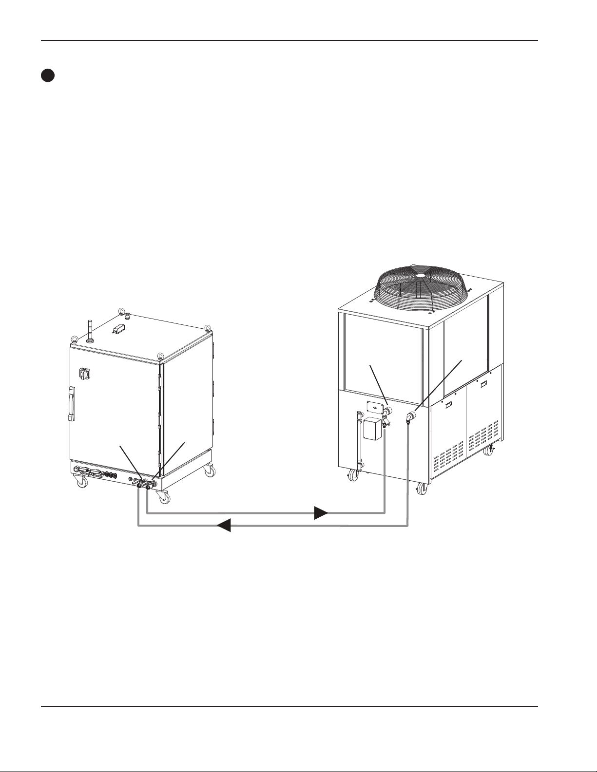
InstallatIon
3
Fiber laser supply to chiller
Note 1: This plumbing is customer supplied. Reinforced Tygon, copper, stainless steel, or PVC pipe is
recommended. Steel and rubber should not be used.
Note 2: The use of a water filter is recommended to meet the water/coolant purity specifications.
SeeChillerrequirements in the Specifications section of this manual.
Input
Return
Return
Output
2-40 HyIntensity Fiber Laser Instruction Manual – 807090 Revision 3
Page 89

Cable connections
4
Hypernet cable: fiber laser supply to a Hypertherm CNC – 223171
10 m (33 ft)
InstallatIon
HyIntensity Fiber Laser Instruction Manual – 807090 Revision 3 2-41
Page 90

InstallatIon
5
Hypernet cable: fiber laser supply to laser head controller – 223171
10 m (33 ft)
2-42 HyIntensity Fiber Laser Instruction Manual – 807090 Revision 3
Page 91

Gas console control cable – 223138
6
This cable connects from the laser head controller to the gas console.
10 m (33 ft)
InstallatIon
Laser head gas control connector pin-outs
Pin Description
1 O2/air pressure feedback
2 Common
11 Chassis
3 N
4 Common
11 Chassis
12 O
10 Common
11 Chassis
14 N
13 Common
16 Chassis
17 Gas fault +24 VDC
15 Common
16 Chassis
23 N
6 Common
16 Chassis
24 Air valve
8 Common
16 Chassis
25 Side jet
22 Common
16 Chassis
26 Purge
33 Common
16 Chassis
35 +24 VDC
34 Common
37 Chassis
/air pressure feedback
2
/air pressure setpoint
2
/air pressure setpoint
2
valve
2
HyIntensity Fiber Laser Instruction Manual – 807090 Revision 3 2-43
Page 92

InstallatIon
7
Laser head I/O cable – 223169
This cable connects from the laser head controller to the laser head.
10 m (33 ft)
Laser head controller I/O connector pin-outs
Pin
1 Common
2 Capacitive height sense
3 Common
4 Spare
5 Common
6 +15 VDC
7 –15 VDC
8 Nozzle extension
9 Lens door
10 Collision
11 Tip touch
12 +10 VDC
Signal
2-44 HyIntensity Fiber Laser Instruction Manual – 807090 Revision 3
Page 93

Gas hoses
8
Gas control console to laser head
InstallatIon
Cut gas hose included with system
Purge hose included with system
10 m (33 ft), White
6 mm outside diameter
10 m (33 ft)
9.5 mm (3/8 in) internal diameter,
thermoplastic hose.
3/8 in tube adaptor end connections.
Minimum bend radius is 2.5 cm
Side-jet hose included with system
10 m (33 ft) black
6 mm outside diameter
HyIntensity Fiber Laser Instruction Manual – 807090 Revision 3 2-45
Page 94

InstallatIon
9
Laser head controller power cable – (customer supplied)
Laser head controller power connector pin-outs
CPC Pin LPC2 Pin Signal
1 A9 24 VDC
2 C9 Common
3 NC NC
Shield screw
4
on connector
housing
Shield
2-46 HyIntensity Fiber Laser Instruction Manual – 807090 Revision 3
Page 95

Line disconnect switch
SWITCH BOX
The line disconnect switch serves as the supply-voltage disconnecting (isolating) device. Install
this switch near the power supply for easy access by the operator. The switch should be fused
for 30 amps, 480 VAC.
InstallatIon
Installation must be performed by a licensed electrician and according to applicable national
and local codes.
The switch should:
• Isolate the electrical equipment and disconnect all live conductors from the supply voltage when in the “OFF”
position
• Have one “OFF” and one “ON” position clearly marked with “O” (OFF) and “l” (ON)
• Have an external operating handle capable of being locked in the “OFF” position
• Contain a power-operated mechanism that serves as an emergency stop
• Have slow-blow fuses installed for the proper breaking capacity
10
Main power cables (fiber laser supply and chiller)
Wire sizes vary based on the distance of the receptacle from the main box. The fiber laser supply must be permanently
connected using rigid or flexible metallic conduit. 10 AWG wire rated for use in conduit is recommended. Installation
must be performed by a licensed electrician.
30 A
HyIntensity Fiber Laser Instruction Manual – 807090 Revision 3 2-47
Page 96

InstallatIon
Connect the power
DANGER
ELECTRICAL SHOCK CAN KILL
The line disconnect switch must be in the OFF position before making the power cable connections.
In the U.S., use a “lock-out/tag-out” procedure until installation is complete. In other countries,
follow appropriate national and local safety procedures.
1. Insert the power cable through the strain relief at the rear of the fiber laser supply.
2. Open the rear door of the fiber laser supply enclosure and locate the main power terminal block.
3. Connect the power leads to the terminals as shown below.
4. Verify that the line disconnect switch is in the OFF position and remains in the OFF position for
the remainder of the installation of the system.
5. Connect the power cord leads to the line disconnect switch following national and local electrical codes.
Wire colors
L1 = Red
L2 = White
L3 = Black
(PE) Earth ground = Green/Yellow
1 L1
3 L2
5 L3
GroundRed White Black
Line disconnect
switch
Power cable
2-48 HyIntensity Fiber Laser Instruction Manual – 807090 Revision 3
Page 97

InstallatIon
Gas requirements
The customer must furnish all gases and gas-supply regulators for the system. Use a high-quality, 2-stage pressure
regulator located within 30 m (100 ft). of the gas console. See gas regulators in this section for recommendations. See
the Specification section for gas and flow specifications.
Note: Oxygen, air and nitrogen are required for all systems. Air is used as a purge gas.
Caution: Gas supply pressures not within the specifications in Section 2 can cause poorcut
quality, poor consumable life and operational problems.
If the purity level of the gas is too low or if there are leaks in the supply hoses or
connections:
• Cut speeds can decrease
• Cut quality can deteriorate
• Cutting thickness capability can decrease
• Parts life can shorten
HyIntensity Fiber Laser Instruction Manual – 807090 Revision 3 2-49
Page 98
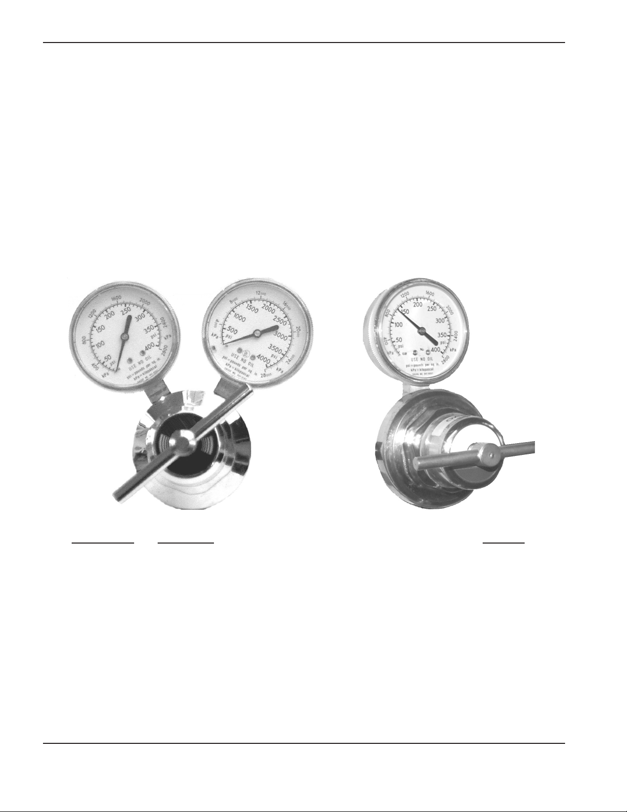
InstallatIon
Gas regulators
Low-quality gas regulators do not provide consistent supply pressures and can result in poor cut quality and system
operation problems. Use a high-quality, 1-stage, gas regulator to maintain consistent gas supply pressure, if using liquid
cryogenic or bulk storage. Use a high-quality, 2-stage, gas regulator to maintain consistent gas supply pressure from
high pressure gas cylinders.
The high-quality gas regulators listed below are available from Hypertherm and meet U.S. Compressed Gas Association
(CGA) specifications. In other countries, select gas regulators that conform to national or local codes.
Single stage regulatorTwo-stage regulator
Part Number Description Quantity
128544 Kit: Oxygen, 2-stage * 1
128547 Kit: Air, 2-stage 1
128548 Kit: 1-stage (for use with cryogenic liquid nitrogen or oxygen) 1
022037 Oxygen, 2-stage 1
022040 Air, 2-stage 1
022041 Line regulator, 1-stage 1
* Kits include appropriate fittings
2-50 HyIntensity Fiber Laser Instruction Manual – 807090 Revision 3
Page 99
InstallatIon
Supply gas plumbing
Rigid copper plumbing or suitable flexible hose may be used for all gas supplies, but they must meet the pressure
requirements (see section 1, Specifications). Do not use steel or aluminum pipe.
After installation, pressurize the entire system and check for leaks.
Recommended hose diameters are 10 mm (3/8 in) for lengths <25 m (82 ft) and 12 mm (1/2 in) for
lengths > 25 m (82 ft).
For flexible-hose systems, use a hose designed for inert gas to carry air, nitrogen.
Caution: When connecting the gas console to the supply gases, make sure that all hoses, hose
connections and fittings are acceptable for use with oxygen. Installation must be made
in accordance with national and local codes.
WARNING
CUTTING WITH OXYGEN CAN CAUSE FIRE OR EXPLOSION
Cutting with oxygen as the assist gas can cause a potential fire hazard due to the oxygen-enriched
atmosphere that it creates. As a precaution, Hypertherm recommends that an exhaust ventilation
system be installed when cutting with oxygen.
Flashback arrestors are required (unless not available for specific gases or required pressures) to
prevent fire from propagating to supply gas.
HyIntensity Fiber Laser Instruction Manual – 807090 Revision 3 2-51
Page 100

InstallatIon
Connect the supply gases
Connect the supply gases to the gas console.
Fitting Size
O
N
2
2
1/4 in NPT female*
1/4 in NPT female**
Air 10 mm OD, push-to-connect
* The customer must furnish gas supply hoses for the system. Recommendations for appropriate fittings/adaptors
andsupply gas hoses can be provided by Hypertherm if necessary. Oxygen hoses in various lengths are available
fromHypertherm.
** The nitrogen hose for use with the fiber laser system must be rated for a working pressure of at least 28 bar
(400psi).
2-52 HyIntensity Fiber Laser Instruction Manual – 807090 Revision 3
 Loading...