

Page 1
HyDefinition
®
HD4070
Plasma Arc Cutting / Marking System
Instruction Manual
803760 – Revision 2
4070.97
Page 2

Changed Page Description
Rev 1 to 2
12/17/01
2.12
Changed dimension from 2.4" to 2.8". 2 rail lifter change.
3.6 & .12,
3A.2 &. 23,
3B.2,.12 &
Updated art to show off-valve cover
.21, 5.3
4.14 & 6.13 Added CCW consumables for 200A M.S.
5.35
Text changed to match figure change in Rev1 (P2 Jumper for 265V is now for
211V block position changed from 265V to 211V)
5.37&5.39 Updated art to show 2 rail lifter.
6.8
Added Lo-Profile Filter art. P/Ns 128714 & 027927 and Pump sub-assembly, P/N
129738. Rearranged order of part #s.
6.11 Gas console art updated. Shows valves in the current orientation.
Lifter assembly P/N (128050) changed to 2 rail version 128606. Driving block P/N
6.17
(027552) changed to 027903. Rail and block bearing P/N (027551) changed to
027904. Lead screw assembly P/N (129266) changed to 129699. AddedP/N
128607- band seal kit.
6.18 P/N (075508) changed to 075583.
6.19 Cable P/N 123596 given an item # (3a).
Page 1
Page 3

Changed Page Description IM376 Rev 0 to 1
4/26/01
Cover
2.5
2.11
iv &3.1
3.3
3.14
3A.3
Section 4
4.5
4.19
5.15 & 5.16
Added HyDefinition to title
H35 percentages corrected to H35 = 35% Hydrogren, 65% Argon
Updated dimension from 2.25" to 3.5" and metric equivalent
Correction to table of contents: 3-19 canged to 3-20, 3-20 to 3-21
Caution box text realigned
Note added under power requirements table (Pg still says 0 not 1.1)
Cables and hoses header changed from German to English
Cutcharts added: 30A S.S. & AL, 70A S.S. & AL, 100A S.S. & AL
Note added "The screen displays the choices..."
English cutchart: ipm & mmm were reversed
Notes added to top of error code tables 1 & 2
5.25 & 26
5.35
6.12
PC-104 art and test procedure removed. Incomplete procedure and parts. Pg
#'s after bumped up
P2 Jumper for 265V is now for 211V block position changed from 265V to
211V
Added part #'s 058224, 044030 & 128654. Renumbered parts, updated art
Page 2
Page 4

HD4070
Instruction Manual
(P/N 803760)
Revision 2 – December, 2001
© Copyright 2001 Hypertherm, Inc.
All Rights Reserved
Hypertherm, HyDefinition and Command THC are trademarks of Hypertherm, Inc.
and may be registered in the United States and/or other countries
Hypertherm, Inc.
Hanover, NH USA
www.hypertherm.com
Page 5

Hypertherm, Inc.
Etna Road, P.O. Box 5010
Hanover, NH 03755 USA
603-643-3441 Tel (Main Office)
603-643-5352 Fax (All Departments)
800-643-9878 Tel (Technical Service)
800-737-2978 Tel (Customer Service)
Hypertherm Automation
5 Technology Drive
West Lebanon, NH 03755 USA
603-298-7970 Tel
603-298-7977 Fax
Hypertherm Plasmatechnik GmbH
Technologiepark Hanau
Rodenbacher Chaussee 6
63457 Hanau-Wolfgang, Deutschland
49 6181 58 2100 Tel
49 6181 58 2134 Fax
49 6181 58 2123 (Technical Service)
Hypertherm Singapore Pte Ltd
No. 19 Kaki Bukit Road 2
K.B. Warehouse Complex
Singapore 417847, Republic of Singapore
65 841 2489 Tel
65 841 2490 Fax
65 841 2489 (Technical Service)
Japan
1952-14 Yata-Natsumegi
Mishima City, Shizuoka Pref.
411-0801 Japan
81 0 559 75 7387 Tel
81 0 559 75 7376 Fax
Hypertherm UK Ltd
9 Berkeley Court, Manor Park
Runcorn, Cheshire, England WA7 1TQ
44 1928 579 074 Tel
44 1928 579 604 Fax
France
15 Impasse des Rosiers
95610 Eragny, France
0805 050 111 Tel
0805 050 222 Fax
Hypertherm S.r.L.
Via Torino 2
20123 Milano, Italia
39 02 725 46 312 Tel
39 02 725 46 400 Fax
39 02 725 46 314 (Technical Service)
Hypertherm B.V.
Burg. Haverkampstraat 13
7091 CN Dinxperlo, Nederland
31 315 655866 Tel
31 315 655886 Fax
Hypertherm B.V. (ETSO)
Vaartveld 9
4704 SE Roosendaal, Nederland
00 800 49 73 7843 – toll-free in Europa
31 165 596900 Tel
31 165 596901 Fax
Hypertherm Brasil Ltda.
Rua Visconde de Santa Isabel, 20 – Sala 611
Vila Isabel, RJ
Brasil CEP 20560-120
55 21 2278 6162 Tel
55 21 2578 0947 Fax
10/30/01
Page 6

ELECTROMAGNETIC COMPATIBILITY (EMC)
EMC INTRODUCTION
Hypertherm's CE-marked equipment is built
in compliance with standard EN50199. The
equipment should be installed and used in
accordance with the information below to
achieve electromagnetic compatibility.
The limits required by EN50199 may not be
adequate to completely eliminate interference when the affected equipment is in
close proximity or has a high degree of
sensitivity. In such cases it may be necessary to use other measures to further
reduce interference.
This plasma equipment is designed for use
only in an industrial environment.
INSTALLATION AND USE
The user is responsible for installing and
using the plasma equipment according to
the manufacturer's instructions. If electromagnetic disturbances are detected then it
shall be the responsibility of the user to resolve the situation with the technical assistance of the manufacturer. In some cases
this remedial action may be as simple as
earthing the cutting circuit, see Earthing of
Workpiece. In other cases it could involve
constructing an electromagnetic screen
enclosing the power source and the work
complete with associated input filters. In all
cases electromagnetic disturbances must
be reduced to the point where they are no
longer troublesome.
ASSESSMENT OF AREA
Before installing the equipment the user
shall make an assessment of potential electromagnetic problems in the surrounding
area. The following shall be taken into
account:
a. Other supply cables, control cables,
signalling and telephone cables; above,
below and adjacent to the cutting equipment.
b. Radio and television transmitters and
receivers.
c. Computer and other control equipment.
d. Safety critical equipment, for example
guarding of industrial equipment.
e. Health of the people around, for
example the use of pacemakers and hearing aids.
f. Equipment used for calibration or measurement.
g. Immunity of other equipment in the environment. User shall ensure that other
equipment being used in the environment is
compatible. This may require additional
protection measures.
h. Time of day that cutting or other activities
are to be carried out.
Earthing of Workpiece
Where the workpiece is not bonded to earth
for electrical safety, nor connected to earth
because of its size and position, for example,
ship's hull or building steelwork, a connection
bonding the workpiece to earth may reduce
emissions in some, but not all instances.
Care should be taken to prevent the earthing
of the workpiece increasing the risk of injury
to users, or damage to other electrical equipment. Where necessary, the connection of
the workpiece to earth should be made by a
direct connection to the workpiece, but in
some countries where direct connection is
not permitted, the bonding should be
achieved by suitable capacitances selected
according to national regulations.
Note. The cutting circuit may or may not be
earthed for safety reasons. Changing the
earthing arrangements should only be authorized by a person who is competent to
assess whether the changes will increase
the risk of injury, for example, by allowing
parallel cutting current return paths which
may damage the earth circuits of other
equipment. Further guidance is given in IEC
TC26 (sec)94 and IEC TC26/108A/CD Arc
Welding Equipment Installation and Use.
Screening and Shielding
Selective screening and shielding of other
cables and equipment in the surrounding
area may alleviate problems of interference.
Screening of the entire plasma cutting
installation may be considered for special
applications
The size of the surrounding area to be
considered will depend on the structure of
the building and other activities that are taking place. The surrounding area may extend
beyond the boundaries of the premises.
METHODS OF REDUCING EMISSIONS
Mains Supply
Cutting equipment must be connected to the
mains supply according to the manufacturer's recommendations. If interference
occurs, it may be necessary to take
additional precautions such as filtering of
the mains supply. Consideration should be
given to shielding the supply cable of permanently installed cutting equipment, in
metallic conduit or equivalent. Shielding
should be electrically continuous throughout
its length. The shielding should be connected to the cutting mains supply so that good
electrical contact is maintained between the
conduit and the cutting power source
enclosure
Maintenance of Cutting Equipment
The cutting equipment must be routinely
maintained according to the manufacturer's
recommendations. All access and service
doors and covers should be closed and
properly fastened when the cutting
equipment is in operation. The cutting
equipment should not be modified in any
way except for those changes and adjustments covered in the manufacturer's
instructions. In particular, the spark gaps of
arc striking and stabilizing devices should
be adjusted and maintained according to
the manufacturer's recommendations.
Cutting Cables
The cutting cables should be kept as short
as possible and should be positioned close
together, running at or close to the floor
level.
Equipotential Bonding
Bonding of all metallic components in the
cutting installation and adjacent to it should
be considered. However, metallic components bonded to the workpiece will increase
the risk that the operator could receive a
shock by touching these metallic
components and the electrode at the same
time. The operator should be insulated from
all such bonded metallic components.
Hypertherm Plasma Systems i
Page 7

WARRANTY
ii Hypertherm Plasma Systems
9-01
WARNING
Genuine Hypertherm parts are the factory-recommended
replacement parts for your Hypertherm system. Any damage
caused by the use of other than genuine Hypertherm parts may
not be covered by the Hypertherm warranty.
WARNING
You are responsible for the safe use of the Product.
Hypertherm does not and cannot make any guarantee or
warranty regarding the safe use of the Product in your
environment.
GENERAL
Hypertherm, Inc. warrants that its Products shall be free from
defects in materials and workmanship, if Hypertherm is notified
of a defect (i) with respect to the power supply within a period
of two (2) years from the date of its delivery to you, with the
exception of G3 Series power supplies, which shall be within a
period of three (3) years from the date of delivery to you, and
(ii) with respect to the torch and leads within a period of one (1)
year from its date of delivery to you. This warranty shall not
apply to any Product which has been incorrectly installed,
modified, or otherwise damaged. Hypertherm, at its sole
option, shall repair, replace, or adjust, free of charge, any
defective Products covered by this warranty which shall be
returned with Hypertherm’s prior authorization (which shall not
be unreasonably withheld), properly packed, to Hypertherm’s
place of business in Hanover, New Hampshire, or to an
authorized Hypertherm repair facility, all costs, insurance and
freight prepaid. Hypertherm shall not be liable for any repairs,
replacement, or adjustments of Products covered by this
warranty, except those made pursuant to this paragraph or with
Hypertherm’s prior written consent. The warranty above is
exclusive and is in lieu of all other warranties, express,
implied, statutory, or otherwise with respect to the
Products or as to the results which may be obtained
therefrom, and all implied warranties or conditions of
quality or of merchantability or fitness for a particular
purpose or against infringement. The foregoing shall
constitute the sole and exclusive remedy for any breach
by Hypertherm of its warranty. Distributors/OEMs may offer
different or additional warranties, but Distributors/OEMs are
not authorized to give any additional warranty protection to you
or make any representation to you purporting to be binding
upon Hypertherm.
PATENT INDEMNITY
Except only in cases of products not manufactured by
Hypertherm or manufactured by a person other than
Hypertherm not in strict conformity with Hypertherm’s
specifications and in cases of designs, processes, formulae, or
combinations not developed or purported to be developed by
Hypertherm, Hypertherm will defend or settle, at its own
expense, any suit or proceeding brought against you alleging
that the use of the Hypertherm product, alone and not in
combination with any other product not supplied by
Hypertherm, infringes any patent of any third party. You shall
notify Hypertherm promptly upon learning of any action or
threatened action in connection with any such alleged
infringement, and Hypertherm’s obligation to indemnify shall be
conditioned upon Hypertherm’s sole control of, and the
indemnified party’s cooperation and assistance in, the defense
of the claim.
LIMITATION OF LIABILITY
In no event shall Hypertherm be liable to any person or
entity for any incidental, consequential, indirect, or
punitive damages (including but not limited to lost profits)
regardless of whether such liability is based on breach of
contract, tort, strict liability, breach of warranties, failure of
essential purpose or otherwise and even if advised of the
possibility of such damages.
LIABILITY CAP
In no event shall Hypertherm’s liability, whether such
liability is based on breach of contract, tort, strict liability,
breach of warranties, failure of essential purpose or
otherwise, for any claim action suit or proceeding arising
out of or relating to the use of the Products exceed in the
aggregate the amount paid for the Products that gave rise
to such claim.
INSURANCE
At all times you will have and maintain insurance in such
quantities and types, and with coverage sufficient and
appropriate to defend and to hold Hypertherm harmless in
the event of any cause of action arising from the use of the
Products.
NATIONAL AND LOCAL CODES
National and Local codes governing plumbing and electrical
installation shall take precedent over any instructions
contained in this manual. In no event shall Hypertherm be
liable for injury to persons or property damage by reason of any
code violation or poor work practices.
TRANSFER OF RIGHTS
You may transfer any remaining rights you may have
hereunder only in connection with the sale of all or substantially
all of your assets or capital stock to a successor in interest who
agrees to be bound by all of the terms and conditions of this
Warranty.
Page 8

TABLE OF CONTENTS
0
HD4070 Instruction Manual iii
Electromagnetic Compatibility (EMC) ...........................................................................................................................i
Warranty.......................................................................................................................................................................ii
General................................................................................................................................................................ii
Patent Indemnity..................................................................................................................................................ii
Limitation of Liability ............................................................................................................................................ii
Liability Cap.........................................................................................................................................................ii
Insurance.............................................................................................................................................................ii
National and Local Codes....................................................................................................................................ii
Transfer of Rights................................................................................................................................................ii
Section 1 Safety...................................................................................................................................................1-1
Recognize Safety Information...................................................................................................................................1-2
Follow Safety Instructions.........................................................................................................................................1-2
Cutting Can Cause Fire or Explosion .......................................................................................................................1-2
Electric Shock Can Kill..............................................................................................................................................1-3
Cutting Can Produce Toxic Fumes...........................................................................................................................1-3
A Plasma Arc Can Cause Injury and Burns ..............................................................................................................1-4
Arc Rays Can Burn Eyes and Skin...........................................................................................................................1-4
Grounding Safety......................................................................................................................................................1-4
Compressed Gas Equipment Safety ........................................................................................................................1-5
Gas Cylinders Can Explode If Damaged..................................................................................................................1-5
Noise Can Damage Hearing.....................................................................................................................................1-5
Pacemaker and Hearing Aid Operation....................................................................................................................1-5
A Plasma Arc Can Damage Frozen Pipes................................................................................................................1-5
Additional Safety Information....................................................................................................................................1-5
Warning Label...........................................................................................................................................................1-6
Section 1a Sécurité............................................................................................................................................1a-1
Identifier les consignes de sécurité.........................................................................................................................1a-2
Suivre les instructions de sécurité ..........................................................................................................................1a-2
Le coupage peut provoquer un incendie ou une explosion....................................................................................1a-2
Les chocs électriques peuvent être fatals...............................................................................................................1a-3
Le coupage peut produire des vapeurs toxiques....................................................................................................1a-3
L'arc plasma peut provoquer des blessures ou des brûlures .................................................................................1a-4
Mise à la masse et à la terre...................................................................................................................................1a-4
Les rayons de l'arc peuvent brûler les yeux et la peau...........................................................................................1a-4
Sécurité des bouteilles de gaz comprimé...............................................................................................................1a-5
Les bouteilles de gaz comprimé peuvent exploser en cas de dommages .............................................................1a-5
Le bruit peut provoquer des problèmes auditifs......................................................................................................1a-5
Pacemakers et prothéses auditives........................................................................................................................1a-5
Étiquette de sécurité...............................................................................................................................................1a-6
Section 2 Specifications .....................................................................................................................................2-1
System Description...................................................................................................................................................2-2
General ............................................................................................................................................................2-2
Power Supply ..................................................................................................................................................2-2
Machine Torch..................................................................................................................................................2-2
Off-V alve Assembly..........................................................................................................................................2-3
Gas Console ....................................................................................................................................................2-3
Ignition Console ...............................................................................................................................................2-3
Options.............................................................................................................................................................2-3
Options – continued.........................................................................................................................................2-4
Specifications............................................................................................................................................................2-5
Page 9

TABLE OF CONTENTS
1.1
iv HD4070 Instruction Manual
System Gas Requirements..............................................................................................................................2-5
Power Supply...................................................................................................................................................2-6
Gas Console Assembly ...................................................................................................................................2-8
Ignition Console Assembly...............................................................................................................................2-9
Off-V alve Assembly........................................................................................................................................2-10
Torch Specifications .......................................................................................................................................2-11
X-Y Lifter Assembly........................................................................................................................................2-12
Torch Breakaway Kit ......................................................................................................................................2-13
Section 3 Installation...........................................................................................................................................3-1
Upon Receipt............................................................................................................................................................3-2
Claims.......................................................................................................................................................................3-2
Installation Requirements .........................................................................................................................................3-2
Gas Requirements....................................................................................................................................................3-2
Torch Coolant Requirements....................................................................................................................................3-3
Water Purity Requirements.......................................................................................................................................3-4
Noise levels ..............................................................................................................................................................3-4
Torch Lifter Requirement ..........................................................................................................................................3-4
Placement of System Components ..........................................................................................................................3-5
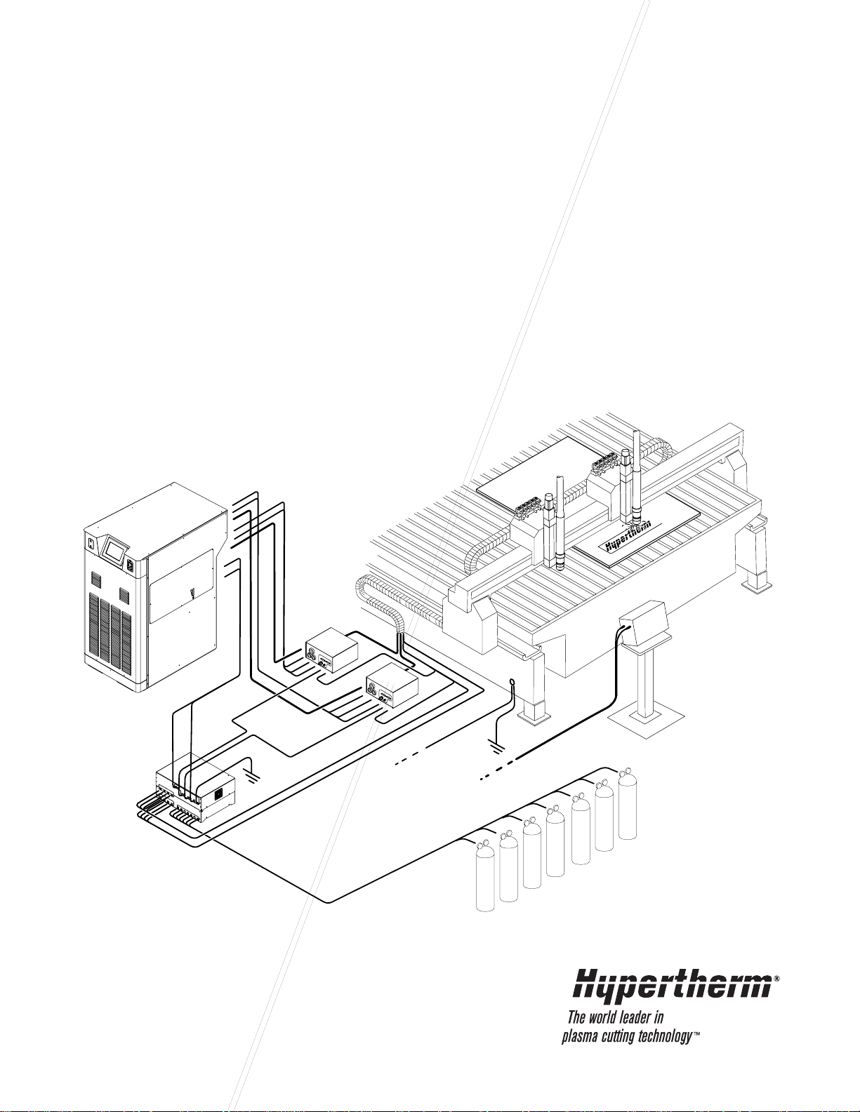
HD4070 Installation – Basic Requirements ..............................................................................................................3-6
Place System Components:.............................................................................................................................3-7
Customer-Supplied Cables and Hoses:...........................................................................................................3-7
Install Cables and Hoses: ................................................................................................................................3-7
Remote Display Option....................................................................................................................................3-7
Placement of the Power Supply.......................................................................................................................3-8
Placement of the Gas Console Assembly........................................................................................................3-9
Mount the Ignition Console Assembly............................................................................................................3-10
Install the Off-Valve Assembly........................................................................................................................3-11
Grounding Requirements........................................................................................................................................3-12
Supply Gas Plumbing .............................................................................................................................................3-13
Connect the Supply Gases ............................................................................................................................3-13
Power Requirements ..............................................................................................................................................3-14
General ..........................................................................................................................................................3-14
Line Disconnect Switch..................................................................................................................................3-14
Power Cable...................................................................................................................................................3-14
Connect the Power.........................................................................................................................................3-15
Install the Power Supply to Gas Console and CNC Cables ...................................................................................3-16
Signal Cable – Power Supply to Gas Console...............................................................................................3-17
Power Cable – Power Supply to Gas Console...............................................................................................3-17
CNC Interface Cable – Power Supply to CNC...............................................................................................3-18
Install the Remote Display Cable............................................................................................................................3-20
Remote Display..............................................................................................................................................3-20
Signal Cable – Power Supply to Remote Display..........................................................................................3-20
Display Mounting Dimensions........................................................................................................................3-21
Section 3A 1 Torch Installation........................................................................................................................3A-1
HD4070 1-Torch Installation...................................................................................................................................3A-2
System Components..............................................................................................................................................3A-3
Cables and Hoses..................................................................................................................................................3A-3
Install the Coolant Hoses...............................................................................................................................3A-4
Coolant Hose Assembly – Green Supply.......................................................................................................3A-5
Coolant Hose Assembly – Red Return..........................................................................................................3A-5
Install the Power Supply to Ignition Console Leads.......................................................................................3A-6
Page 10

TABLE OF CONTENTS
0
HD4070 Instruction Manual v
Install the Work Lead.....................................................................................................................................3A-6
Pilot Arc Lead.................................................................................................................................................3A-7
Negative Lead................................................................................................................................................3A-7
Work Lead .....................................................................................................................................................3A-7
Install the Gas Console to Ignition Console Cable ........................................................................................3A-8
Cable – Gas Console to Ignition Console......................................................................................................3A-9
Install the Ignition Console to Off-Valve Cable and Gas Hose Assembly....................................................3A-10
Hoses – Gas Console to Off-Valve .............................................................................................................3A-11
Cable – Ignition Console to Off-Valve..........................................................................................................3A-11
Cable – Off-Valve ........................................................................................................................................3A-11
THC and Torch Installation...................................................................................................................................3A-12
X-Y Lifter Assembly .....................................................................................................................................3A-12
Torch Mounting Block Kit ............................................................................................................................3A-13
Torch Breakaway Kit (Optional) ..................................................................................................................3A-14
Install the Torch (without torch breakaway option).......................................................................................3A-16
Install the Torch (with torch breakaway option)............................................................................................3A-17
Integrated Command THC Option – Cable Installation ...............................................................................3A-18
Cable – Lifter Interface ................................................................................................................................3A-19
Cable – Motor Drive.....................................................................................................................................3A-19
Ohmic Contact Wire.....................................................................................................................................3A-19
Lifter interface cable signals........................................................................................................................3A-20
Motor drive cable signals.............................................................................................................................3A-20
Torch Connections................................................................................................................................................3A-21
Connecting the Torch to Torch Leads..........................................................................................................3A-21
Torch Mounting and Alignment ....................................................................................................................3A-22
Install the Torch and Lead Assembly....................................................................................................................3A-23
Torch and Lead Assembly............................................................................................................................3A-23
Fill the Power Supply with Coolant.......................................................................................................................3A-24
Section 3B 2 Torch Installation........................................................................................................................3B-1
HD4070 2-Torch Installation...................................................................................................................................3B-2
System Components..............................................................................................................................................3B-3
Cables and Hoses..................................................................................................................................................3B-3
Install the Coolant Hoses...............................................................................................................................3B-4
Coolant Hose Assembly – Green Supply.......................................................................................................3B-5
Coolant Hose Assembly – Red Return..........................................................................................................3B-5
Install the Pilot Arc Leads..............................................................................................................................3B-6
Pilot Arc Lead.................................................................................................................................................3B-7
Install the Negative and Work Leads.............................................................................................................3B-8
Negative Lead................................................................................................................................................3B-9
Work Lead .....................................................................................................................................................3B-9
Install the Gas Console to Ignition Console Cable ......................................................................................3B-10
Cable – Gas Console to Ignition Console....................................................................................................3B-11
Install the Gas Hose Assembly....................................................................................................................3B-12
Hoses – Gas Console to Off-valve .............................................................................................................3B-13
Install the Ignition Console to Off-Valve Cables...........................................................................................3B-14
Cable – Ignition Console to Off-valve..........................................................................................................3B-15
Cable – Off-Valve ........................................................................................................................................3B-15
Install the Integrated Command THC Option ......................................................................................................3B-16
Cable – Lifter Interface ................................................................................................................................3B-17
Cable – Motor Drive.....................................................................................................................................3B-17
Ohmic Contact Wire.....................................................................................................................................3B-17
Lifter interface cable signals........................................................................................................................3B-18
Motor drive cable signals.............................................................................................................................3B-18
Page 11

TABLE OF CONTENTS
1
vi HD4070 Instruction Manual
Torch Connections................................................................................................................................................3B-19
Connecting the Torch to Torch Leads..........................................................................................................3B-19
Torch Mounting and Alignment ....................................................................................................................3B-20
Install the Torch and Lead Assembly....................................................................................................................3B-21
Torch and Lead Assembly............................................................................................................................3B-21
Fill the Power Supply with Coolant.......................................................................................................................3B-22
Section 4 Operation.............................................................................................................................................4-1
Power Supply Controls and Indicators......................................................................................................................4-2
General ............................................................................................................................................................4-2
Power Switch ...................................................................................................................................................4-2
Power Indicators ..............................................................................................................................................4-2
Power Supply Display......................................................................................................................................4-3
System Setup screens navigation ............................................................................................................................4-4
System Operation screens navigation......................................................................................................................4-6
Daily Start-up............................................................................................................................................................4-7
Check Torch.....................................................................................................................................................4-7
Turn Power Supply ON....................................................................................................................................4-8
System Setup Screens.....................................................................................................................................4-8
System Operation Screens ............................................................................................................................4-11
Consumables Selection..........................................................................................................................................4-14
Install Consumables ...............................................................................................................................................4-15
Cut Charts...............................................................................................................................................................4-16
Changing Consumable Parts..................................................................................................................................4-29
Remove Consumables...................................................................................................................................4-29
Inspect Consumables.....................................................................................................................................4-30
Inspect Torch..................................................................................................................................................4-31
Inspect Electrode Pit Depth............................................................................................................................4-32
Replace Torch Water Tube .....................................................................................................................................4-33
Common Cutting Faults..........................................................................................................................................4-34
Cutting Techniques.................................................................................................................................................4-35
How to Get Better Cut Quality........................................................................................................................4-35
How to Get Longer Consumable Life.............................................................................................................4-37
How to Get Better Pierces..............................................................................................................................4-38
How to Increase Cutting Speed .....................................................................................................................4-38
Technical Questions................................................................................................................................................4-38
Section 5 Maintenance........................................................................................................................................5-1
Introduction...............................................................................................................................................................5-2
Routine Maintenance................................................................................................................................................5-2
HD4070 System Description.....................................................................................................................................5-3
Control and Signal Cables ...............................................................................................................................5-3
Power Supply Coolant System Servicing .................................................................................................................5-4
Torch Coolant Draining.............................................................................................................................................5-6
Power Supply Coolant Draining................................................................................................................................5-6
Coolant System Filter and Strainer...........................................................................................................................5-7
Coolant Flow Test Procedure....................................................................................................................................5-9
HD4070 Process Sequence ...................................................................................................................................5-10
Initial Checks...........................................................................................................................................................5-12
Power Measurement...............................................................................................................................................5-13
Service Display Screens.........................................................................................................................................5-14
Error Codes ............................................................................................................................................................5-15
Error Code Trouble Shooting (1 of 4).............................................................................................................5-16
Error Code Trouble Shooting (2 of 4).............................................................................................................5-17
Page 12

TABLE OF CONTENTS
1
HD4070 Instruction Manual vii
Error Code Troubleshooting- 3 of 4................................................................................................................5-18
Error Code Troubleshooting- 4 of 4................................................................................................................5-19
Electrical PC Boards and Power Supplies..............................................................................................................5-20
Plasma Interface Board PCB5 status Indicators............................................................................................5-21
Breakout Board PCB6 status Indicators.........................................................................................................5-22
Control Board PCB3 status Indicators ...........................................................................................................5-26
Power Distribution Board PCB4 Status Indicators.........................................................................................5-27
Start Circuit Assembly Board PCB2...............................................................................................................5-28
Pilot Arc Current Levels..................................................................................................................................5-28
Start Circuit Functional Schematic.................................................................................................................5-29
Start Circuit Troubleshooting..........................................................................................................................5-29
Gas Console Relay Board PCB1...................................................................................................................5-30
Gas Console Relay Board PCB3...................................................................................................................5-32
Gas Console Control Board PCB2 .........................................................................................................................5-34
Leak Test Procedure...............................................................................................................................................5-35
Chopper Module Test Procedure............................................................................................................................5-36
Phase Loss Detection Board PCB1 Status Indicators and Operation....................................................................5-38
THC Routine Maintenance .....................................................................................................................................5-39
X-Y Lifter Sealing Band- Replace ..................................................................................................................5-39
THC Motor Drive Board ..........................................................................................................................................5-43
THC Power Supply .................................................................................................................................................5-44
THC Control Board .................................................................................................................................................5-45
Preventive Maintenance Schedule.........................................................................................................................5-47
Section 6 Parts List .............................................................................................................................................6-1
Power Supply............................................................................................................................................................6-2
Front Panel Outside.........................................................................................................................................6-2
Left Side Interior...............................................................................................................................................6-3
Right Side Interior ............................................................................................................................................6-4
PC Boards and Interlock Switches...................................................................................................................6-5
I/O Panel..........................................................................................................................................................6-6
Control Box: Shown with Parts for Two THC Option.......................................................................................6-7
Cooling System................................................................................................................................................6-8
Ignition Console .......................................................................................................................................................6-9
Gas Console – 1 of 2..............................................................................................................................................6-10
Gas Console – 2 of 2 ..............................................................................................................................................6-11
HD4070 Torch.........................................................................................................................................................6-12
Consumable Configurations ...................................................................................................................................6-13
Consumable Parts Kit.............................................................................................................................................6-14
Off-valve Assembly.................................................................................................................................................6-15
Recommended Spare Parts ...................................................................................................................................6-15
Integrated Command THC......................................................................................................................................6-17
X-Y Lifter Assembly........................................................................................................................................6-17
X-Y Lifter Torch Mounting Block Kit................................................................................................................6-18
X-Y Lifter Breakaway Kit – Optional...............................................................................................................6-19
Ohmic Contact Wire ......................................................................................................................................6-20
Least Replaceable Units List ..................................................................................................................................6-21
Section 7 Wiring Diagrams .................................................................................................................................7-1
Introduction...............................................................................................................................................................7-1
Wiring Diagram Symbols ..........................................................................................................................................7-2
Gas and Electrical Schematics.................................................................................................................................7-4
Page 13

TABLE OF CONTENTS
0
viii HD4070 Instruction Manual
Appendix A System Grounding.............................................................................................................................a-1
System Grounding Requirements.............................................................................................................................a-1
Suggested Ground Cable Routing............................................................................................................................a-1
Power Supply...................................................................................................................................................a-1
Equipment Grounding......................................................................................................................................a-1
Work Table Grounding......................................................................................................................................a-2
Appendix B Propylene Glycol Safety Data........................................................................................................b-1
Benzotriazole Safety Data..............................................................................................................b-1
Appendix C Gas Regulators ...............................................................................................................................c-1
Appendix D Service Screen (#18) Status Table ..................................................................................................d-1
Appendix E Integrated Command THC Supplemental Information ................................................................e-1
Command THC serial protocol..................................................................................................................................e-2
CNC Serial Interface.................................................................................................................................................e-4
Appendix F PC-104 Stack: Jumper Positions....................................................................................................f-1
Page 14

Hypertherm Plasma Systems 1-1
Section 1
SAFETY
In this section:
Recognize Safety Information.........................................................................................................................1-2
Follow Safety Instructions...............................................................................................................................1-2
Cutting Can Cause Fire or Explosion..............................................................................................................1-2
Electric Shock Can Kill....................................................................................................................................1-3
Cutting Can Produce Toxic Fumes..................................................................................................................1-3
A Plasma Arc Can Cause Injury and Burns.....................................................................................................1-4
Arc Rays Can Burn Eyes and Skin .................................................................................................................1-4
Grounding Safety............................................................................................................................................1-4
Compressed Gas Equipment Safety...............................................................................................................1-5
Gas Cylinders Can Explode If Damaged ........................................................................................................1-5
Noise Can Damage Hearing...........................................................................................................................1-5
Pacemaker and Hearing Aid Operation...........................................................................................................1-5
A Plasma Arc Can Damage Frozen Pipes ......................................................................................................1-5
Additional Safety Information..........................................................................................................................1-5
Warning Label.................................................................................................................................................1-6
Page 15
SAFETY
1-2 Hypertherm Plasma Systems
11-98
SAFETY
RECOGNIZE SAFETY INFORMATION
The symbols shown in this section are used to
identify potential hazards. When you see a safety
symbol in this manual or on your machine, understand
the potential for personal injury, and follow the related
instructions to avoid the hazard.
FOLLOW SAFETY INSTRUCTIONS
Read carefully all safety messages in this manual and
safety labels on your machine.
• Keep the safety labels on your machine in good
condition. Replace missing or damaged labels
immediately.
• Learn how to operate the machine and how to use
the controls properly. Do not let anyone operate it
without instruction.
• Keep your machine in proper working condition.
Unauthorized modifications to the machine may
affect safety and machine service life.
DANGER WARNING CAUTION
A signal word DANGER or WARNING is used with a
safety symbol. DANGER identifies the most serious
hazards.
• DANGER and WARNING safety labels are located
on your machine near specific hazards.
• WARNING safety messages precede related
instructions in this manual that may result in injury
or death if not followed correctly.
• CAUTION safety messages precede related
instructions in this manual that may result in
damage to equipment if not followed correctly.
Fire Prevention
• Be sure the area is safe before doing any cutting.
Keep a fire extinguisher nearby.
• Remove all flammables within 35 feet (10 m) of the
cutting area.
• Quench hot metal or allow it to cool before handling
or before letting it touch combustible materials.
• Never cut containers with potentially flammable
materials inside – they must be emptied and
properly cleaned first.
• Ventilate potentially flammable atmospheres before
cutting.
• When cutting with oxygen as the plasma gas, an
exhaust ventilation system is required.
Explosion Prevention
• Do not use the plasma system if explosive dust or
vapors may be present.
• Do not cut pressurized cylinders, pipes, or any
closed container.
• Do not cut containers that have held combustible
materials.
CUTTING CAN CAUSE FIRE OR EXPLOSION
WARNING
Explosion Hazard
Argon-Hydrogen and Methane
Hydrogen and methane are flammable gases that
present an explosion hazard. Keep flames away from
cylinders and hoses that contain methane or hydrogen
mixtures. Keep flames and sparks away from the torch
when using methane or argon-hydrogen plasma.
WARNING
Hydrogen Detonation with Aluminum Cutting
• When cutting aluminum underwater, or with the
water touching the underside of the aluminum, free
hydrogen gas may collect under the workpiece and
detonate during plasma cutting operations.
• Install an aeration manifold on the floor of the water
table to eliminate the possibility of hydrogen
detonation. Refer to the Appendix section of this
manual for aeration manifold details.
Page 16
Touching live electrical parts can cause a fatal shock
or severe burn.
• Operating the plasma system completes an
electrical circuit between the torch and the
workpiece. The workpiece and anything touching
the workpiece are part of the electrical circuit.
• Never touch the torch body, workpiece or the water
in a water table when the plasma system is
operating.
Electric Shock Prevention
All Hypertherm plasma systems use high voltage
in the cutting process (200 to 400 VDC are
common). Take the following precautions when
operating this system:
• Wear insulated gloves and boots, and keep your
body and clothing dry.
• Do not stand, sit or lie on – or touch – any wet
surface when using the plasma system.
• Insulate yourself from work and ground using dry
insulating mats or covers big enough to prevent any
physical contact with the work or ground. If you must
work in or near a damp area, use extreme caution.
• Provide a disconnect switch close to the power
supply with properly sized fuses. This switch allows
the operator to turn off the power supply quickly in
an emergency situation.
• When using a water table, be sure that it is correctly
connected to earth ground.
ELECTRIC SHOCK CAN KILL
• Install and ground this equipment according to the
instruction manual and in accordance with national
and local codes.
• Inspect the input power cord frequently for damage
or cracking of the cover. Replace a damaged power
cord immediately. Bare wiring can kill.
• Inspect and replace any worn or damaged torch
leads.
• Do not pick up the workpiece, including the waste
cutoff, while you cut. Leave the workpiece in place
or on the workbench with the work cable attached
during the cutting process.
• Before checking, cleaning or changing torch parts,
disconnect the main power or unplug the power
supply.
• Never bypass or shortcut the safety interlocks.
• Before removing any power supply or system
enclosure cover, disconnect electrical input power.
Wait 5 minutes after disconnecting the main power
to allow capacitors to discharge.
• Never operate the plasma system unless the power
supply covers are in place. Exposed power supply
connections present a severe electrical hazard.
• When making input connections, attach proper
grounding conductor first.
• Each Hypertherm plasma system is designed to be
used only with specific Hypertherm torches. Do not
substitute other torches which could overheat and
present a safety hazard.
Cutting can produce toxic fumes and gases that
deplete oxygen and cause injury or death.
• Keep the cutting area well ventilated or use an
approved air-supplied respirator.
• Do not cut in locations near degreasing, cleaning or
spraying operations. The vapors from certain
chlorinated solvents decompose to form phosgene
gas when exposed to ultraviolet radiation.
• Do not cut metal coated or containing toxic materials, such as zinc (galvanized), lead, cadmium or
CUTTING CAN PRODUCE TOXIC FUMES
beryllium, unless the area is well ventilated and the
operator wears an air-supplied respirator. The
coatings and any metals containing these elements
can produce toxic fumes when cut.
• Never cut containers with potentially toxic materials
inside – they must be emptied and properly cleaned
first.
• This product, when used for welding or cutting,
produces fumes or gases which contain chemicals
known to the State of California to cause birth
defects and, in some cases, cancer.
Hypertherm Plasma Systems 1-3
8-99
SAFETY
Page 17
SAFETY
1-4 Hypertherm Plasma Systems
4-99
SAFETY
Instant-On Torches
Plasma arc comes on immediately when the torch
switch is activated.
A PLASMA ARC CAN CAUSE INJURY AND BURNS
The plasma arc will cut quickly through gloves and
skin.
• Keep away from the torch tip.
• Do not hold metal near the cutting path.
• Never point the torch toward yourself or others.
Eye Protection Plasma arc rays produce intense
visible and invisible (ultraviolet and infrared) rays that
can burn eyes and skin.
• Use eye protection in accordance with applicable
national or local codes.
• Wear eye protection (safety glasses or goggles with
side shields, or a welding helmet) with appropriate
lens shading to protect your eyes from the arc’s
ultraviolet and infrared rays.
Lens Shade
Arc Current AWS (USA) ISO 4850
Up to 100 A No. 8 No. 11
100-200 A No. 10 No. 11-12
200-400 A No. 12 No. 13
Over 400 A No. 14 No. 14
ARC RAYS CAN BURN EYES AND SKIN
Skin Protection Wear protective clothing to protect
against burns caused by ultraviolet light, sparks and
hot metal.
• Gauntlet gloves, safety shoes and hat.
• Flame-retardant clothing to cover all exposed areas.
• Cuffless trousers to prevent entry of sparks and
slag.
• Remove any combustibles, such as a butane lighter
or matches, from your pockets before cutting.
Cutting Area Prepare the cutting area to reduce
reflection and transmission of ultraviolet light:
• Paint walls and other surfaces with dark colors to
reduce reflection.
• Use protective screens or barriers to protect others
from flash and glare.
• Warn others not to watch the arc. Use placards or
signs.
Work Cable Attach the work cable securely to the
workpiece or the work table with good metal-to-metal
contact. Do not connect it to the piece that will fall
away when the cut is complete.
Work Table Connect the work table to an earth
ground, in accordance with appropriate national or
local electrical codes.
GROUNDING SAFETY
Input Power
• Be sure to connect the power cord ground wire to
the ground in the disconnect box.
• If installation of the plasma system involves
connecting the power cord to the power supply, be
sure to connect the power cord ground wire
properly.
• Place the power cord's ground wire on the stud first,
then place any other ground wires on top of the
power cord ground. Fasten the retaining nut tightly.
• Tighten all electrical connections to avoid excessive
heating.
Page 18
SAFETY
Hypertherm Plasma Systems 1-5
11-98
SAFETY
• Never lubricate cylinder valves or regulators with oil
or grease.
• Use only correct gas cylinders, regulators, hoses
and fittings designed for the specific application.
• Maintain all compressed gas equipment and
associated parts in good condition.
• Label and color-code all gas hoses to identify the
type of gas in each hose. Consult applicable
national or local codes.
GAS CYLINDERS CAN
EXPLODE IF DAMAGED
COMPRESSED GAS EQUIPMENT SAFETY
Gas cylinders contain gas under high pressure. If
damaged, a cylinder can explode.
• Handle and use compressed gas cylinders in
accordance with applicable national or local codes.
• Never use a cylinder that is not upright and secured
in place.
• Keep the protective cap in place over valve except
when the cylinder is in use or connected for use.
• Never allow electrical contact between the plasma
arc and a cylinder.
• Never expose cylinders to excessive heat, sparks,
slag or open flame.
• Never use a hammer, wrench or other tool to open
a stuck cylinder valve.
Prolonged exposure to noise from cutting or gouging
can damage hearing.
• Use approved ear protection when using plasma
system.
• Warn others nearby about the noise hazard.
NOISE CAN DAMAGE HEARING
Pacemaker and hearing aid operation can be affected
by magnetic fields from high currents.
Pacemaker and hearing aid wearers should consult a
doctor before going near any plasma arc cutting and
gouging operations.
To reduce magnetic field hazards:
• Keep both the work cable and the torch lead to one
side, away from your body.
• Route the torch leads as close as possible to the
work cable.
• Do not wrap or drape the torch lead or work cable
around your body.
• Keep as far away from the power supply as
possible.
P ACEMAKER AND HEARING
AID OPERATION
ADDITIONAL SAFETY INFORMATION
1. ANSI Standard Z49.1, Safety in Welding and Cutting, American
Welding Society, 550 LeJeune Road
P.O. Box 351020, Miami, FL33135
2. ANSI Standard Z49.2, Fire Prevention in the Use of Cutting and
Welding Processes, American National Standards Institute
1430 Broadway, New York, NY 10018
3. ANSI Standard Z87.1, Safe Practices for Occupation and
Educational Eye and Face Protection, American National
Standards Institute, 1430 Broadway, New York, NY 10018
4. AWS F4.1, Recommended Safe Practices for the Preparation for
Welding and Cutting of Containers and Piping That Have Held
Hazardous Substances, American Welding Society
550 LeJeune Road, P.O. Box 351040, Miami, FL33135
5. AWS F5.2, Recommended Safe Practices for Plasma Arc
Cutting, American Welding Society
550 LeJeune Road, P.O. Box 351040, Miami, FL33135
6. CGA Pamphlet P-1, Safe Handling of Compressed Gases in
Cylinders, Compressed Gas Association
1235 Jefferson Davis Highway, Arlington, VA22202
7. CSA Standard W117.2, Code for Safety in Welding and Cutting,
Canadian Standards Association Standard Sales
178 Rexdale Boulevard, Rexdale, Ontario M9W 1R3, Canada
8. NFPAStandard 51B, Cutting and Welding Processes, National
Fire Protection Association
470 Atlantic Avenue, Boston, MA 02210
9. NFPAStandard 70–1978, National Electrical Code, National Fire
Protection Association, 470 Atlantic Avenue, Boston, MA 02210
10. OSHA, Safety and Health Standards, 29FR 1910
U.S. Government Printing Office, Washington, D.C. 20402
A PLASMA ARC CAN
DAMAGE FROZEN PIPES
Frozen pipes may be damaged or can burst if you
attempt to thaw them with a plasma torch.
Page 19
SAFETY
1-6 Hypertherm Plasma Systems
8-99
SAFETY
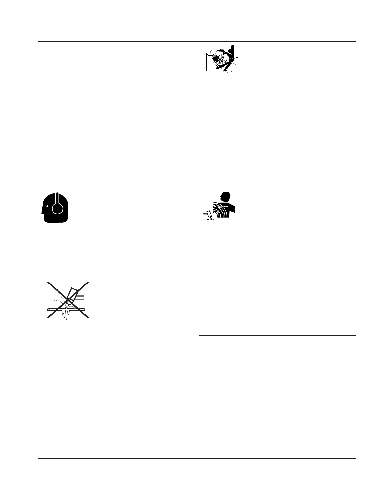
WARNING LABEL
This warning label is affixed to some power supplies. It is
important that the operator and maintenance technician
understand the intent of these warning symbols as described.
The numbered text corresponds to the numbered boxes on
the label.
1. Cutting sparks can cause explosion or fire.
1.1 Keep flammables away from cutting.
1.2 Keep a fire extinguisher nearby, and have
a watchperson ready to use it.
1.3 Do not cut on any closed containers.
2. The plasma arc can cause injury and
burns.
2.1 Turn off power before disassembling torch.
2.2 Do not hold the material near cutting path.
2.3 Wear complete body protection.
3. Electric shock from torch or wiring can kill.
Protect yourself from electric shock.
3.1 Wear insulating gloves. Do not wear wet or
damaged gloves.
3.2 Insulate yourself from work and ground.
3.3 Disconnect input plug or power before
working on machine.
4. Breathing cutting fumes can be hazardous
to your health.
4.1 Keep your head out of the fumes.
4.2 Use forced ventilation or local exhaust to
remove the fumes.
4.3 Use ventilating fan to remove the fumes.
5. Arc rays can burn eyes and injure skin.
5.1 Wear hat and safety glasses. Use ear
protection and button shirt collar. Use
welding helmet with correct shade of filter.
Wear complete body protection.
6. Become trained and read the instructions
before working on the machine or cutting.
7. Do not remove or paint over (cover)
warning labels.
Page 20

Hypertherm Systèmes plasma 1a-1
2/12/01
Section 1a
SÉCURITÉ
Dans cette section :
Identifier les consignes de sécurité...............................................................................................................1a-2
Suivre les instructions de sécurité.................................................................................................................1a-2
Danger Avertissement Précaution...............................................................................................................1a-2
Le coupage peut provoquer un incendie ou une explosion...........................................................................1a-2
Prévention des incendies, Prévention des explosions .........................................................................1a-2
Risque d’explosion argon-hydrogène et méthane................................................................................1a-2
Détonation de l’hydrogène lors du coupage de l’aluminium.................................................................1a-2
Les chocs électriques peuvent être fatals.....................................................................................................1a-3
Prévention des chocs électriques.........................................................................................................1a-3
Le coupage peut produire des vapeurs toxiques..........................................................................................1a-3
L’arc plasma peut provoquer des blessures ou des brûlures........................................................................1a-4
Torches à allumage instantané.............................................................................................................1a-4
Les rayons de l’arc peuvent brûler les yeux et la peau.................................................................................1a-4
Protection des yeux, Protection de la peau, Zone de coupage ..........................................................1a-4
Mise à la masse et à la terre.........................................................................................................................1a-4
Câble de retour, Table de travail, Alimentation.....................................................................................1a-4
Sécurité des bouteilles de gaz comprimé .....................................................................................................1a-5
Les bouteilles de gaz comprimé peuvent exploser en cas de dommages....................................................1a-5
Le bruit peut provoquer des problèmes auditifs............................................................................................1a-5
Pacemakers et prothèses auditives..............................................................................................................1a-5
Un arc plasma peut endommager les tuyaux gelés......................................................................................1a-5
Étiquette de sécurité .....................................................................................................................................1a-6
Page 21
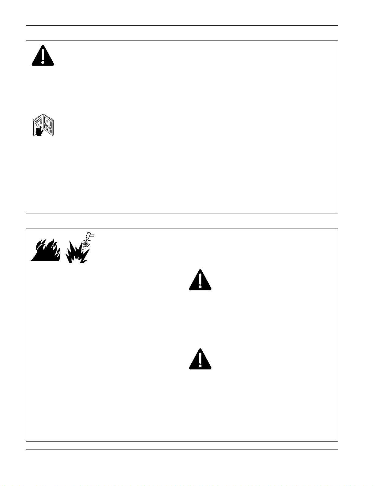
SÉCURITÉ
1a-2 Hypertherm Systèmes plasma
2/12/01
IDENTIFIER LES CONSIGNES
DE SÉCURITÉ
Les symboles indiqués dans cette section sont utilisés pour
identifier les risques éventuels. Si vous trouvez un symbole
de sécurité, que ce soit dans ce manuel ou sur
l’équipement, soyez conscient des risques de blessures et
suivez les instructions correspondantes afin d’éviter ces
risques.
SUIVRE LES INSTRUCTIONS
DE SÉCURITÉ
Lire attentivement toutes les consignes de sécurité dans le
présent manuel et sur les étiquettes de sécurité se trouvant
sur la machine.
• Les étiquettes de sécurité doivent rester lisibles.
Remplacer immédiatement les étiquettes manquantes ou
abîmées.
• Apprendre à faire fonctionner la machine et à utiliser
correctement les commandes. Ne laisser personne utiliser
la machine sans connaître son fonctionnement.
• Garder la machine en bon état. Des modifications non
autorisées sur la machine peuvent engendrer des
problèmes de sécurité et raccourcir la durée d’utilisation
de l’équipement.
DANGER AVERTISSEMENT PRÉCAUTION
Les signaux DANGER ou AVERTISSEMENT sont utilisés
avec un symbole de sécurité, DANGER correspondant aux
risques les plus sérieux.
• Les étiquettes de sécurité DANGER et AVERTISSEMENT
sont situées sur la machine pour signaler certains
dangers spécifiques.
• Les messages d’AVERTISSEMENT précèdent les
instructions d’utilisation expliquées dans ce manuel et
signalent les risques de blessures ou de mort au cas où
ces instructions ne seraient pas suivies correctement.
• Les messages de PRÉCAUTION précèdent les
instructions d’utilisation contenues dans ce manuel et
signalent que le matériel risque d’être endommagé si les
instructions ne sont pas suivies correctement.
Prévention des incendies
• Avant de commencer, s’assurer que la zone de coupage
ne présente aucun danger. Conserver un extincteur à
proximité.
• Éloigner toute matière inflammable à une distance d’au
moins 10 m du poste de coupage.
• Tremper le métal chaud ou le laisser refroidir avant de
le manipuler ou avant de le mettre en contact avec des
matériaux combustibles.
• Ne jamais couper des récipients pouvant contenir des
matières inflammables avant de les avoir vidés et
nettoyés correctement.
• Aérer toute atmosphère potentiellement inflammable
avant d’utiliser un système plasma.
• Lors de l’utilisation d’oxygène comme gaz plasma, un
système de ventilation par aspiration est nécessaire.
Prévention des explosions
• Ne pas couper en présence de poussière ou de vapeurs.
• Ne pas couper de bouteilles, de tuyaux ou autres
récipients fermés et pressurisés.
• Ne pas couper de récipients contenant des matières
combustibles.
LE COUPAGE PEUT PROVOQUER UN INCENDIE
OU UNE EXPLOSION
AVERTISSEMENT
Risque d’explosion
argon-hydrogène et méthane
L’hydrogène et le méthane sont des gaz inflammables et
potentiellement explosifs. Conserver à l’écart de toute
flamme les bouteilles et tuyaux contenant des mélanges à
base d’hydrogène ou de méthane. Maintenir toute flamme
et étincelle à l’écart de la torche lors de l’utilisation d’un
plasma d’argon-hydrogène ou de méthane.
AVERTISSEMENT
Détonation de l’hydrogène lors du
coupage de l’aluminium
• Lors du coupage de l’aluminium sous l’eau, ou si l’eau
touche la partie inférieure de la pièce d’aluminium, de
l’hydrogène libre peut s’accumuler sous la pièce à couper
et détonner lors du coupage plasma.
• Installer un collecteur d’aération au fond de la table à eau
afin d’éliminer les risques de détonation de l’hydrogène.
Se référer à l’annexe du manuel pour plus de
renseignements sur les collecteurs d’aération.
Page 22

SÉCURITÉ
Hypertherm Systèmes plasma 1a-3
2/12/01
Toucher une pièce électrique sous tension peut provoquer
un choc électrique fatal ou des brûlures graves.
• La mise en fonctionnement du système plasma ferme un
circuit électrique entre la torche et la pièce à couper. La
pièce à couper et tout autre élément en contact avec cette
pièce font partie du circuit électrique.
• Ne jamais toucher le corps de la torche, la pièce à couper
ou l’eau de la table à eau pendant le fonctionnement du
système plasma.
Prévention des chocs électriques
Tous les systèmes plasma Hypertherm utilisent des hautes
tensions pour le coupage (souvent de 200 à 400 V). On
doit prendre les précautions suivantes quand on utilise le
système plasma :
• Porter des bottes et des gants isolants et garder le corps
et les vêtements au sec.
• Ne pas se tenir, s’asseoir ou se coucher sur une surface
mouillée, ni la toucher quand on utilise le système plasma.
• S’isoler de la surface de travail et du sol en utilisant des
tapis isolants secs ou des couvertures assez grandes
pour éviter tout contact physique avec le travail ou le sol.
S’il s’avère nécessaire de travailler dans ou près d’un
endroit humide, procéder avec une extrême prudence.
• Installer un sectionneur avec fusibles appropriés, à
proximité de la source de courant. Ce dispositif permet à
l’opérateur d’arrêter rapidement la source de courant en
cas d’urgence.
• En cas d’utilisation d’une table à eau, s’assurer que cette
dernière est correctement mise à la terre.
LES CHOCS ÉLECTRIQUES PEUVENT ÊTRE FATALS
• Installer et mettre à la terre l’équipement selon les
instructions du présent manuel et conformément aux
codes électriques locaux et nationaux.
• Inspecter fréquemment le cordon d’alimentation primaire
pour s’assurer qu’il n’est ni endommagé, ni fendu.
Remplacer immédiatement un cordon endommagé.
Un câble dénudé peut tuer.
• Inspecter et remplacer les câbles de la torche qui sont
usés ou endommagés.
• Ne pas saisir la pièce à couper ni les chutes lors du
coupage. Laisser la pièce à couper en place ou sur la
table de travail, le câble de retour connecté lors du
coupage.
• Avant de vérifier, de nettoyer ou de remplacer les pièces
de la torche, couper l’alimentation ou débrancher la prise
de courant.
• Ne jamais contourner ou court-circuiter les verrouillages
de sécurité.
• Avant d’enlever le capot du système ou de la source de
courant, couper l’alimentation électrique. Attendre en
suite
5 minutes pour que les condensateurs se déchargent.
• Ne jamais faire fonctionner le système plasma sans que
les capots de la source de courant ne soient en place.
Les raccords exposés de la source de courant sont
extrêmement dangereux.
• Lors de l’installation des connexions, attacher tout d’abord
la prise de terre appropriée.
• Chaque système plasma Hypertherm est conçu pour être
utilisé uniquement avec des torches Hypertherm
spécifiques. Ne pas utiliser des torches inappropriées qui
pourraient surchauffer et présenter des risques pour la
sécurité.
Le coupage peut produire des vapeurs et des gaz toxiques
qui réduisent le niveau d’oxygène dans l’air et peuvent
provoquer des blessures, voire la mort.
• Conserver le poste de coupage bien aéré ou utiliser un
masque respiratoire homologué.
• Ne pas procéder au coupage près d’endroits où
s’effectuent le dégraissage, le nettoyage ou la vaporisation. Certains solvants chlorés se décomposent sous
l’effet des rayons ultraviolets et forment du phosgène.
• Ne pas couper des métaux peints ou contenant des
matières toxiques comme le zinc (galvanisé), le plomb, le
cadmium ou le béryllium, à moins que la zone de travail
LE COUPAGE PEUT PRODUIRE DES VAPEURS TOXIQUES
soit très bien ventilée et que l’opérateur porte un masque
respiratoire. Les revêtements et métaux contenant ces
matières peuvent produire des vapeurs toxiques lors du
coupage.
• Ne jamais couper de récipients pouvant contenir des
matières inflammables avant de les avoir vidés et
nettoyés correctement.
• Quand on utilise ce produit pour le soudage ou le
coupage, il dégage des fumées et des gaz qui
contiennent des produits chimiques qui, selon l’État de
Californie, provoquent des anomalies congénitales et,
dans certains cas, le cancer.
Page 23
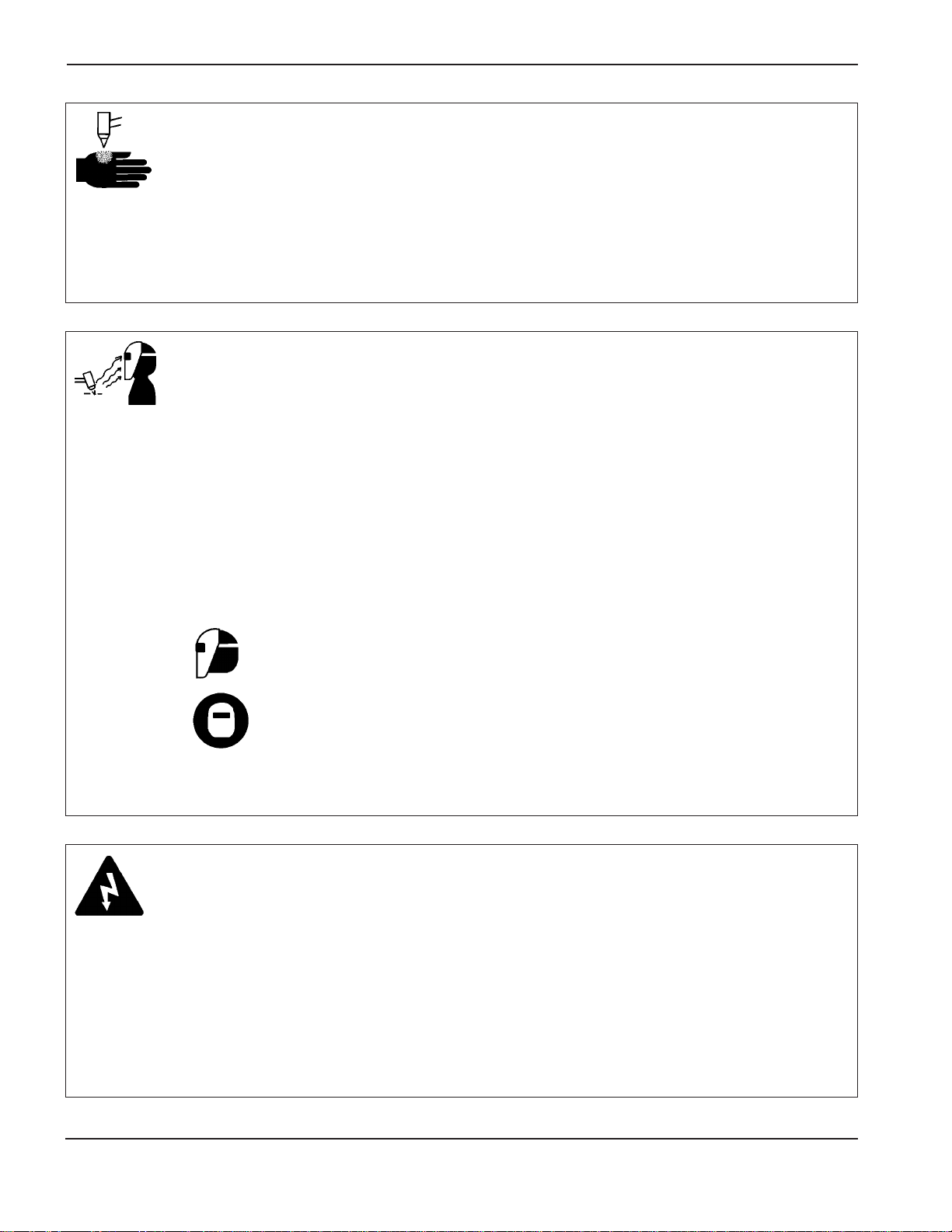
SÉCURITÉ
1a-4 Hypertherm Systèmes plasma
2/12/01
Torches à allumage instantané
L’arc plasma s’allume immédiatement après que la torche
soit mise en marche.
L’ARC PLASMAPEUT PROVOQUER DES BLESSURES OU DES BRÛLURES
L’arc plasma coupe facilement les gants et la peau.
• Rester éloigné de l’extrémité de la torche.
• Ne pas tenir de métal près de la trajectoire de coupe.
• Ne jamais pointer la torche vers soi ou d’autres
personnes.
Protection des yeux Les rayons de l’arc plasma
produisent de puissants rayons visibles ou invisibles
(ultraviolets et infrarouges) qui peuvent brûler les yeux et la
peau.
• Utiliser des lunettes de sécurité conformément aux codes
locaux ou nationaux en vigueur.
• Porter des lunettes de protection (lunettes ou masque
muni d’écrans latéraux ou encore masque de soudure)
avec des verres teintés appropriés pour protéger les yeux
des rayons ultraviolets et infrarouges de l’arc.
Puissance des verres teintés
Courant de l’arc AWS (É.-U.) ISO 4850
Jusqu’à 100 A No8N
o
11
100-200 A No10 No11-12
200-400 A No12 No13
Plus de 400 A No14 No14
Protection de la peau Porter des vêtements de sécurité
pour se protéger contre les brûlures que peuvent causer les
rayons ultraviolets, les étincelles et le métal brûlant :
LES RAYONS DE L’ARC PEUVENT BRÛLER LES YEUX ET LA PEAU
• Gants à crispin, chaussures et casque de sécurité.
• Vêtements ignifuges couvrant toutes les parties exposées
du corps.
• Pantalon sans revers pour éviter que des étincelles ou
des scories puissent s’y loger.
• Avant le coupage, retirer de ses poches tout objet
combustible comme les briquets au butane ou les
allumettes.
Zone de coupage Préparer la zone de coupage afin de
réduire la réverbération et la transmission de la lumière
ultraviolette :
• Peindre les murs et autres surfaces de couleur sombre
pour réduire la réflexion de la lumière.
• Utiliser des écrans et autres dispositifs de protection afin
de protéger les autres personnes de la lumière et de la
réverbération.
• Prévenir les autres personnes de ne pas regarder l’arc.
Utiliser des affiches ou des panneaux.
Câble de retour Bien fixer le câble de retour (ou de
masse) à la pièce à couper ou à la table de travail de façon
à assurer un bon contact métal-métal. Ne pas fixer le câble
de retour à la partie de la pièce qui doit se détacher.
Table de travail Raccorder la table de travail à la terre,
conformément aux codes de sécurité locaux ou nationaux
appropriés.
MISE À LA MASSE ET À LA TERRE
Alimentation
• S’assurer que le fil de terre du cordon d’alimentation est
connecté à la terre dans le coffret du sectionneur.
• S’il est nécessaire de brancher le cordon d’alimentation à
la source de courant lors de l’installation du système,
s’assurer que le fil de terre est correctement branché.
• Placer tout d’abord le fil de terre du cordon d’alimentation
sur le plot de mise à la terre puis placer les autres fils de
terre par-dessus. Bien serrer l’écrou de retenue.
• S’assurer que toutes les connexions sont bien serrées
pour éviter la surchauffe.
Page 24
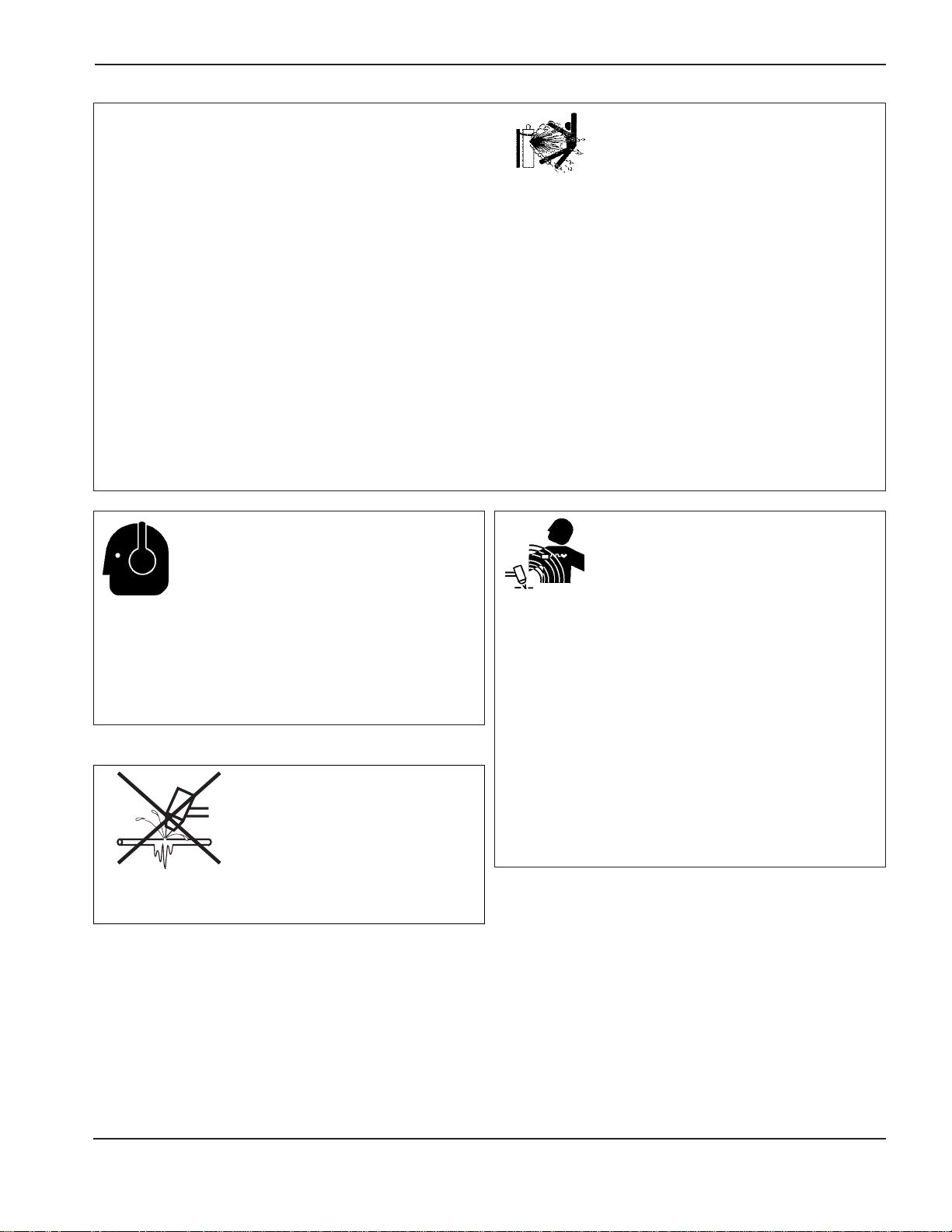
SÉCURITÉ
Hypertherm Systèmes plasma 1a-5
2/12/01
• Ne jamais lubrifier les robinets des bouteilles ou les
régulateurs avec de l’huile ou de la graisse.
• Utiliser uniquement les bouteilles, régulateurs, tuyaux et
accessoires appropriés et conçus pour chaque application
spécifique.
• Entretenir l’équipement et les pièces d’équipement à gaz
comprimé afin de les garder en bon état.
• Étiqueter et coder avec des couleurs tous les tuyaux de
gaz afin d’identifier le type de gaz contenu dans chaque
tuyau. Se référer aux codes locaux ou nationaux en
vigueur.
LES BOUTEILLES DE GAZ
COMPRIMÉ PEUVENT EXPLOSER
EN CAS DE DOMMAGES
SÉCURITÉ DES BOUTEILLES DE
GAZ COMPRIMÉ
Les bouteilles de gaz contiennent du gaz à haute pression.
Si une bouteille est endommagée, elle peut exploser.
• Manipuler et utiliser les bouteilles de gaz comprimé
conformément aux codes locaux ou nationaux.
• Ne jamais utiliser une bouteille qui n’est pas placée à la
verticale et bien assujettie.
• Le capuchon de protection doit être placé sur le robinet
sauf si la bouteille est en cours d’utilisation ou connectée
pour utilisation.
• Éviter à tout prix le contact électrique entre l’arc plasma et
une bouteille.
• Ne jamais exposer des bouteilles à une chaleur
excessive, aux étincelles, aux scories ou aux flammes
nues.
• Ne jamais utiliser des marteaux, des clés ou d’autres
outils pour débloquer le robinet des bouteilles.
Une exposition prolongée au bruit du coupage ou du
gougeage peut provoquer des problèmes auditifs.
• Utiliser un casque de protection homologué lors de
l’utilisation du système plasma.
• Prévenir les personnes aux alentours des risques
encourus en cas d’exposition au bruit.
LE BRUIT PEUT PROVOQUER DES
PROBLÈMES AUDITIFS
Les champs magnétiques produits par les courants à haute
tension peuvent affecter le fonctionnement des prothèses
auditives et des pacemakers. Les personnes portant ce
type d’appareil doivent consulter un médecin avant de
s’approcher d’un lieu où s’effectue le coupage ou le
gougeage plasma.
Pour réduire les risques associés aux champs magnétiques :
• Garder loin de soi et du même côté du corps le câble de
retour et le faisceau de la torche.
• Faire passer le faisceau de la torche le plus près possible
du câble de retour.
• Ne pas s’enrouler le faisceau de la torche ou le câble de
retour autour du corps.
• Se tenir le plus loin possible de la source de courant.
PACEMAKERS ET
PROTHÈSES AUDITIVES
Les tuyaux gelés peuvent être endommagés ou éclater
si l'on essaie de les dégeler avec une torche plasma.
UN ARC PLASMA
PEUT ENDOMMAGER
LES TUYAUX GELÉS
Page 25
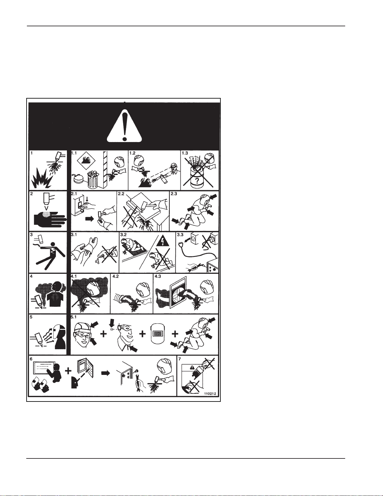
SÉCURITÉ
1a-6 Hypertherm Systèmes plasma
2/12/01
Étiquette de sécurité
Cette étiquette est affichée sur la source de courant. Il est important
que l’utilisateur et le technicien de maintenance comprennent la
signification des symboles de sécurité. Les numéros de la liste
correspondent aux numéros des images.
1. Les étincelles produites par le coupage
peuvent provoquer une explosion ou un
incendie.
1.1 Pendant le coupage, éloigner toute matière
inflammable.
1.2 Conserver un extincteur à proximité et
s’assurer qu’une personne soit prête à
l’utiliser.
1.3 Ne jamais couper de récipients fermés.
2. L’arc plasma peut provoquer des blessures
et des brûlures.
2.1 Couper l’alimentation avant de démonter la
torche.
2.2 Ne pas tenir la surface à couper près de la
trajectoire de coupe.
2.3 Porter des vêtements de protection
couvrant tout le corps.
3. Un choc électrique causé par la torche ou
les câbles peut être fatal. Se protéger
contre les risques de chocs électriques.
3.1 Porter des gants isolants. Ne pas porter de
gants mouillés ou abîmés.
3.2 S’isoler de la surface de travail et du sol.
3.3 Débrancher la prise ou la source de
courant avant de manipuler l’équipement.
4. L’inhalation des vapeurs produites par le
coupage peut être dangereuse pour la
santé.
4.1 Garder le visage à l’écart des vapeurs.
4.2 Utiliser un système de ventilation par
aspiration ou d’échappement localisé pour
dissiper les vapeurs.
4.3 Utiliser un ventilateur pour dissiper les
vapeurs.
5. Les rayons de l’arc peuvent brûler les yeux
et provoquer des lésions de la peau.
5.1 Porter un casque et des lunettes de
sécurité. Se protéger les oreilles et porter
une chemise dont le col peut être
déboutonné. Porter un casque de soudure
dont la protection filtrante est suffisante.
Porter des vêtements protecteurs couvrant
la totalité du corps.
6. Se former à la technique du coupage et lire
les instructions avant de manipuler
l’équipement ou de procéder au coupage.
7. Ne pas retirer ou peindre (recouvrir) les
étiquettes de sécurité.
Page 26

HD4070 Instruction Manual 2-1
0
Section 2
SPECIFICATIONS
In this section:
System Description.........................................................................................................................................2-2
General...................................................................................................................................................2-2
Power Supply ........................................................................................................................................2-2
Machine Torch........................................................................................................................................2-2
Off-V alve Assembly ................................................................................................................................2-3
Gas Console...........................................................................................................................................2-3
Ignition Console......................................................................................................................................2-3
Options...................................................................................................................................................2-3
Options - continued ................................................................................................................................2-4
Specifications..................................................................................................................................................2-5
System Gas Requirements.....................................................................................................................2-5
Power Supply .........................................................................................................................................2-6
Gas Console Assembly - 078085...........................................................................................................2-8
Ignition Console Assembly - 078088......................................................................................................2-9
Off-Valve Assembly - 129563 ...............................................................................................................2-10
Torch Specifications..............................................................................................................................2-11
X-Y Lifter Assembly..............................................................................................................................2-12
Torch Breakaway Kit - 128281......................................................................................................................2-13
Page 27
SPECIFICATIONS
1
2-2 HD4070 Instruction Manual
System Description
General
The HD4070 is a fully automated 200-amp plasma cutting system that requires minimal input and adjustment by
the operator. Using the HD4070 display touch screen (or CNC), the operator enters the material and thickness to
be cut. The HD4070 system automatically selects and adjusts the power and gas required to optimize cutting,
including amperage, gas and gas flow rate.
Power supply
The power supply houses two 100-amp, 15 kHz choppers to produce up to 200Aof constant current DC output. The
HD4070 power supply provides the energy to cut 1/2" mild steel at up to 90 ipm (12 mm at up to 2515 mm/min).
Machine torch
The machine torch can cut 1/2" mild steel at 90 ipm (12 mm at up to 2515 mm/min). The maximum production
cutting capability of the torch is 3/4 inch (19 mm) HyDefinition and 1 inch (25 mm) conventional cutting. To achieve
consumable long life, all cuts must begin and end on the plate surface.
4070.97
Page 28

SPECIFICATIONS
0
HD4070 Instruction Manual 2-3
Off-valve assembly
The off-valve assembly consists of 5 solenoid valves, a manifold block and a wiring harness with connector. The
assembly interfaces with the machine torch, the ignition console and the gas console.
Gas console
The gas console manages all incoming gasses for selection and flow rate and is controlled by the HD4070 power
supply. The gas console includes motor valves, solenoid valves, check valves and pressure transducers, all
mounted on a single manifold assembly. The manifold significantly reduces gas leaks by eliminating the use of
flexible hose. The gas console also houses 2 relay PC boards and a control PC board.
Ignition console
The ignition console generates a high-voltage, high-frequency signal and couples it to the cathode lead and pilot
arc lead. The ignition console is fully electronic, eliminating the use of a spark gap assembly.
Options
• 2-Torch Option - The HD4070 plasma cutting system has the ability to support 2 torches operated from a
single power supply and gas console. When one torch is selected for cutting, the second torch is in the offmode. This allows operators to configure the system for 2 different processes (i.e. 100-amp consumables
installed in one torch and 200-amp consumables installed in the second torch), and to select one torch or
the other from the HD4070 display (or CNC).
• Integrated Command THC Option - The Hypertherm Integrated Command THC takes full advantage of
the HD4070's automated capabilities. When the operator enters the material and thickness to be cut, using
the HD4070 display touch screen (or CNC), the Integrated Command THC automatically adjusts the torch
settings required for the specific process, including arc volts, torch-to-work distance, initial pierce height and
pierce time delay, using the plasma arc voltage to control the torch-to-work distance during cutting. IHS is
accomplished by ohmic contact sensing or by limited- force stall detection. HD4070 power supplies that are
equipped with the Integrated Command THC option include the THC motor drive board, the THC control PC
board and THC power supply required for torch lifter operation and control.
• X-Y lifter assembly (page 2-12) The torch lifter station, under control of the THC control module,
positions a- torch head vertically above the workpiece. Its maximum stroke is 8 inches (200 mm) between
the home and lower-limit switches. It is driven by a stepper motor attached to a leadscrew. An encoder is
provided for stall IHS sensing, and to detect gross errors during normal operation. Alower limit switch
detects maximum travel in the downward direction. Ahome switch is provided to detect when the lifter is
in the uppermost position. Apower-off brake is energized after power-up, and allows controlled motion of
the torch. It is powered on during "Maintenance Mode" to prevent the torch from being accidentally
moved. An optional torch breakaway kit is available.
• Torch Breakaway Kit (optional page 2-13) The torch breakaway (collision sensor) provides a level of
protection for the torch, lifter and X-Y table. Air pressure locks the torch to the THC lifter assembly. The
air pressure can be adjusted to change the force required to trip the breakaway. Upon side impact, the
breakaway releases from the lock position and allows the torch to float.See Page 2-12 for torch mounting
dimensions with and with out the breakaway.
Page 29

SPECIFICATIONS
0
2-4 HD4070 Instruction Manual
Options - continued
• Touch Screen Display Option - The HD4070 display is a touch screen that provides all system control
functions and plasma process information at a single location. The torch consumables that are required
for the selected process are also listed. The power supply may be ordered in three configurations.
• No display
• Display installed in power supply
• Display for installation at a remote location
Warning: The HD4070 system can only support one touch screen display, either local or remote.
Installing displays at both locations on one system may cause malfunctions or damage.
Page 30
SPECIFICATIONS
1.1
HD4070 Instruction Manual 2-5
Specifications
System gas requirements
Gas Quality and Pressure Requirements
Quality Pressure + 5% Flow Rate
O2Oxygen 99.5% pure (liquid gas recommended) 120 psi 133 scfh (3780 l/h)
Clean, dry, oil-free 8.3 bar / 827 kPa
N2Nitrogen 99.99% pure (liquid gas recommended) 120 psi 142 scfh 4020 l/h
Clean, dry, oil-free 8.3 bar / 827 kPa
Air Clean, dry, oil-free 120 psi 140 scfh 3960 l/h
8.3 bar / 827 kPa
CH4Methane 93% pure 120 psi 188 scfh 5340 l/h
8.3 bar / 827 kPa
H5 Argon-Hydrogen 99.995% pure (liquid gas recommended) 120 psi 122 scfh 3420 l/h
(H5=5% Hydrogen, 95% Argon) 8.3 bar / 827 kPa
H35 Argon-Hydrogen 99.995% pure (liquid gas recommended) 120 psi 146 scfh 4140 l/h
(H35=35% Hydrogen, 65% Argon) 8.3 bar / 827 kPa
CO2Carbon-Dioxide 99.5% pure 120 psi 113 scfh 3180 l/h
8.3 bar / 827 kPa
Mild Steel Stainless Steel Aluminum
Gas Types Plasma Shield Plasma Shield Plasma Shield
Marking N
2
N
2
H5 N
2
H5 N
2
Cutting 30 A O
2
O2& N
2
Air Air Air Air
Cutting 70 A O
2
O2& N
2
H35 & N
2
N
2
Air CH4& Air
Cutting 100 Ato 200 A O
2
O2& N
2
H35 & N
2
N
2
H35 & N
2
N
2
Page 31

SPECIFICATIONS
1
2-6 HD4070 Instruction Manual
Power Supply
General
Maximum OCV (U0) 311 VDC
Maximum Output Current (I2) 200 amps
Output Voltage (U2) 85 - 200 VDC
Duty Cycle Rating (X) 100% @ 40 kw, 104°F (40°C)
Ambient Temperature/Duty Cycle Power supplies will operate between +14° and 104°F
( -10°C and +40°C)
Power Factor(cosϕ) 0.98 @ 200A DC output
Cooling Forced Air (Class F)
Input Power (Input Voltage (U1) X Input Current (I1X 1.73)
200 VAC, 3ph, 50-60 Hz, 125A
220 VAC, 3ph, 50-60 Hz, 113A
240 VAC, 3ph, 60 Hz, 103A
400 VAC CE, 3ph, 50-60 Hz, 62A
440 VAC, 3ph, 50-60 Hz, 56A
480 VAC, 3ph, 60 Hz, 52A
600 VAC, 3ph, 60 Hz, 41A
50.5"
1283 mm
39.4"
1001 mm
34.9"
886 mm
15.6"
396 mm
5"
127 mm
1068 lb
484.9 kg
24.25"
616 mm
34.4"
874 mm
4070.42
Page 32

SPECIFICATIONS
0
HD4070 Instruction Manual 2-7
Voltage Options
Power Supply
480V 240V 400V 200V 440V 220V 600V Display 1 THC 2 THC
Part Number 60 HZ 60 HZ 50-60HZ 50-60HZ 50-60 HZ 50-60 HZ 60 HZ
078087 X ––––––nnn
078101 X ––––––nXn
078102 X ––––––nnX
078103 X ––––––Xnn
078104 X ––––––XXn
078105 X ––––––XnX
078134 – X –––––nnn
078147 – X –––––nXn
078148 – X –––––nnX
078149 – X –––––Xnn
078150 – X –––––XXn
078151 – X –––––XnX
078089 ––X ––––nnn
078090 ––X ––––nXn
078091 ––X ––––nnX
078092 ––X ––––Xnn
078093 ––X ––––XXn
078094 ––X ––––XnX
078135 –––X –––nnn
078136 –––X –––nXn
078137 –––X –––nnX
078138 –––X –––Xnn
078139 –––X –––XXn
078140 –––X –––XnX
078095 ––––X –– nnn
078096 ––––X –– nXn
078097 ––––X –– nnX
078098 ––––X –– Xnn
078099 ––––X –– XXn
078100 ––––X –– XnX
078141 –––––X – nnn
078142 –––––X – nXn
078143 –––––X – nnX
078144 –––––X – Xnn
078145 –––––X – XXn
078146 –––––X – XnX
078106 ––––––X nnn
078107 ––––––XnXn
078108 ––––––XnnX
078109 ––––––XXnn
078110 ––––––XXXn
078111 ––––––XXnX
Page 33

94 lb
42.7 kg
11.625"
295 mm
18.75"
476 mm
24.75"
629 mm
1/4-20
22.75" / 578 mm
17.0"
432 mm
4070.20A
SPECIFICATIONS
0
2-8 HD4070 Instruction Manual
Gas console assembly - 078085
Position the gas console near the cutting table. Allow room to open the top for servicing.
Venting air is drawn in through fans on both sides and is exhausted through the front of the unit.
Maximum distance from the power supply should not exceed 150 feet (46 m).
Maximum distance to the off-valve assembly should not exceed 100 feet (30.5 m).
Page 34

4070.19A
0
0
1.25" / 32 mm
11.0"
279 mm
9.75"
248 mm
0.28"
7 mm
1.25"
32 mm
10.63" / 270 mm
4070.21
6.25"
159 mm
11.25"
286 mm
12"
305 mm
20.5 lb
9.3 kg
Horizontal Mounting
Vertical Mounting
Ignition console assembly - 078088
• Mount the ignition console up to 15 feet (4.5 m) from the torch lifter station. Allow room to remove the top
for servicing.
• The ignition console may be mounted in the horizontal or the vertical position as shown below.
SPECIFICATIONS
0
HD4070 Instruction Manual 2-9
Page 35

SPECIFICATIONS
0
2-10 HD4070 Instruction Manual
Off-valve assembly - 129563
• Mount the off-valve assembly up to 4 feet (1.5 m) from the torch lifter station.
4070.18A
A
A
A - A
6.18"
157 mm
1.18"
30 mm
0.187"
4.7 mm
0.75"
19 mm
6.5"
165 mm
3"
76 mm
2.75"
70 mm
2.5 lb
1.1 kg
Page 36

SPECIFICATIONS
1.1
HD4070 Instruction Manual 2-11
Torch Specifications
4 ft / 1.2 m
14.7 lb
6.7 kg
15 ft / 4.5 m
10.86"
(276 mm)
2"
(51 mm)
(89 mm)
3.5"
2.25"
(57 mm)
1.05"
(27
mm)
0.9 kg
2 lb
4.65"
(118 mm)
1.88"
(48 mm)
1.98"
(50 mm)
4070.44
Page 37

SPECIFICATIONS
2
2-12 HD4070 Instruction Manual
X-Y Lifter Assembly
Electrical
Motor.................................................................................+ 2.48 VDC, 2-phase (3.3 amp per ph.)
Limit switches....................................................................+ 24 VDC
Lifter Control Function
Motor.................................................................................Stepper
Motor Drive........................................................................Stepper, chopped constant current
Lifter Feedback .................................................................Encoder
Lifter Limit Switches..........................................................Home switch and lower limit switch
Maximum Z Axis Speed....................................................200 inches (508 cm) per minute
Maximum Z Axis Stroke....................................................8 inches (203 mm)
Torch Mounting Dimensions
Without Breakaway With Breakaway
21.8"
(554 mm)
2.8"
(71 mm)
THC.66a
18 lb
(8.2 kg)
5"
(127 mm)
4.67"
119 mm
5.78"
164 mm
Page 38

SPECIFICATIONS
0
HD4070 Instruction Manual 2-13
X-Y Lifter Breakaway Option
Torch Breakaway Kit - 128281
Electrical
Pressure switch.................................................................CNC emergency stop circuit voltage
Breakaway Control Function
Shop air pressure..............................................................100 psi (6.9 bar) maximum
Size
Breakaway width...............................................................3.8 inches (97 mm)
Breakaway height (thickness)...........................................2.25 inches (57 mm)
Air filter/regulator height....................................................7.06 inches (179 mm)
Air filter/regulator width .....................................................1.56 inches (40 mm)
Air filter/regulator depth (from gauge to back)...................3.125 inches (79 mm)
Weight
Breakaway unit..................................................................1.9 pounds (0.86 kg)
Air filter/regulator...............................................................1.0 pounds (0.45 kg)
Pressure Switch
Breakaway Unit
Air Pressure
Inlet Port
Air Filter/Regulator
Page 39

HD4070 Instruction Manual 3-1
1.1
Section 3
INSTALLATION
In this section:
Upon Receipt ..................................................................................................................................................3-2
Claims.............................................................................................................................................................3-2
Installation Requirements................................................................................................................................3-2
Gas Requirements..........................................................................................................................................3-2
Torch Coolant Requirements...........................................................................................................................3-3
Water Purity Requirements.............................................................................................................................3-4
Noise levels.....................................................................................................................................................3-4
Torch Lifter Requirement.................................................................................................................................3-4
Placement of System Components.................................................................................................................3-5
HD4070 Installation - Basic Requirements .....................................................................................................3-6
Place System Components:...................................................................................................................3-7
Customer-Supplied Cables and Hoses: .................................................................................................3-7
Install Cables and Hoses:.......................................................................................................................3-7
Remote Display Option...................................................................................................................................3-7
Placement of the Power Supply .............................................................................................................3-8
Placement of the Gas Console Assembly..............................................................................................3-9
Mount the Ignition Console Assembly..................................................................................................3-10
Install the Off-Valve Assembly ..............................................................................................................3-11
Grounding Requirements..............................................................................................................................3-12
Supply Gas Plumbing....................................................................................................................................3-13
Connect the Supply Gases...................................................................................................................3-13
Power Requirements.....................................................................................................................................3-14
General.................................................................................................................................................3-14
Line Disconnect Switch ........................................................................................................................3-14
Power Cable.........................................................................................................................................3-14
Connect the Power...............................................................................................................................3-15
Install the Power Supply to Gas Console and CNC Cables..........................................................................3-16
Signal Cable – Power Supply to Gas Console.....................................................................................3-17
Power Cable – Power Supply to Gas Console.....................................................................................3-17
CNC Interface Cable - Power Supply to CNC......................................................................................3-18
Install the Remote Display Cable..................................................................................................................3-20
Remote Display....................................................................................................................................3-20
Signal Cable – Power Supply to Remote Display.................................................................................3-20
Display Mounting Dimensions..............................................................................................................3-21
Page 40

INSTALLATION
0
3-2 HD4070 Instruction Manual
Upon Receipt
• Verify that all system components on your order have been received. Contact your supplier if any items are
missing.
• Inspect the system components for any physical damage that may have occurred during shipping. If there is
evidence of damage, refer to Claims. All communications regarding claims must include the model number and
serial number located on the back of the power supply.
Claims
Claims for damage during shipment – If your unit was damaged during shipment, you must file a claim with the
carrier. Hypertherm will furnish you with a copy of the bill of lading upon request. If you need additional assistance,
call Customer Service listed in the front of this manual, or your authorized Hypertherm distributor.
Claims for defective or missing merchandise – If any of the merchandise is defective or missing, contact your
supplier. If you need additional assistance, call Customer Service listed in the front of this manual, or your
authorized Hypertherm distributor.
Installation Requirements
All installation and service of the electrical and plumbing systems must conform to national or local
electrical and plumbing codes. This work should be performed only by qualified, licensed personnel.
Direct any technical questions to the nearest Hypertherm Technical Service Department listed in the front of this
manual, or your authorized Hypertherm distributor.
Gas Requirements
The customer furnishes all gases and gas-supply regulators for the system. Use a high-quality, 2-stage pressure
regulator located within 10 ft (3 m) of the gas console. See Appendix C for gas regulator recommendations. Refer
to Section 2 for gas and flow specifications.
CAUTION: Gas supply pressures not within the specifications in Section 2 can cause poor
cut quality, poor consumable life and operational problems.
If the purity level of the gas is too low (or too high in the case of methane) or if there
are leaks in the supply hoses or connections,
• Cut speeds can decrease
• Cut quality can deteriorate
• Cutting thickness capability can decrease
• Parts life can shorten
Page 41

INSTALLATION
HD4070 Instruction Manual 3-3
1.1
Torch Coolant Requirements
The power supply is shipped without any coolant in the tank. Hypertherm recommends a mixture of 30% propylene
glycol, 69.9% deionized water, and 0.1% benzotriazole. This mixture resists freezing to +10° F (-12° C) and
contains a corrosion inhibitor to protect copper surfaces in the coolant loop. This mixture is available in 1-gallon
containers by ordering 028872. 100% propylene glycol is available by ordering 028873.
CAUTION: For operating temperatures colder than the temperature stated above, the
percentage of propylene glycol must be increased. Failure to do so could result
in a cracked torch head, hoses or other damage to the torch coolant system due
to freezing.
See Appendix B to determine if a stronger propylene glycol:purified water solution is needed for your particular
application.
Observe the warning and cautions below. Refer to the Material Safety Data Sheets in Appendix B for data on
safety, handling and storage of propylene glycol and benzotriazole.
WARNING
COOLANT CAN BE IRRITATING TO SKIN AND EYES AND
HARMFUL OR FATAL IF SWALLOWED
Propylene glycol and benzotriazole are irritating to skin and eyes, and harmful or fatal if
swallowed. Upon contact, flush skin or eyes with water. If swallowed, drink water and call a
physician immediately. Do not induce vomiting.
Caution: Always use propylene glycol in the coolant mixture. Do not use automotive anti-
freeze in place of propylene glycol. Antifreeze contains corrosion inhibitors that
will damage the torch coolant system.
Caution: Always use purified water in the coolant mixture in order to prevent corrosion in
the torch coolant system. See Water Purity Requirements.
Page 42

INSTALLATION
0
3-4 HD4070 Instruction Manual
Water Purity Requirements
It is critical to maintain a low level of calcium carbonate in the coolant to avoid reduced performance of the torch or
cooling system. Water purity should meet the requirements defined below.
Noise levels
Acceptable noise levels as defined by national or local codes may be exceeded by this plasma system. Always
wear proper ear protection when cutting or gouging. See also Noise Protection in the Safety section of this manual.
Water Purity
Conductivity Resistivity Dissolved Grains per
Water Purity µS/cm MΩ/cm Solids Gallon
at 77° F (25 °C) at 77° F (25 °C) (ppm of NaCl) (gpg of CaCO2)
Pure Water
(reference only) 0.055 18.3 0 0
Maximum Purity 0.5 2 0.206 0.010
Minimum Purity 18 0.054 8.5 0.43
Max. Potable Water
(reference only) 1000 0.001 495 25
Torch Lifter Requirement
The HD4070 system requires a high-quality, motorized torch lifter with sufficient travel to cover all cutting thickness
requirements. The lifter must provide 8 inches (203 mm) of vertical travel. The unit should have the capability of
maintaining a constant speed of up to 200 ipm (5080 mm/min) with positive braking. Aunit which drifts through the
stop point is not acceptable.
Page 43

INSTALLATION
0
HD4070 Instruction Manual 3-5
Placement of System Components
• Place all system components in position prior to making electrical, gas and interface connections. Use the
diagram on the following page for component placement guidelines.
• Ground all system components to earth. See Grounding Requirements in this section for details.
• To prevent leaks in the system, tighten all gas and water connections as shown below:
Torque Specifications
Gas or Water
Hose Size lbf-in lbf-ft kgf-cm
Up to 3/8" (10 mm) 75-85 6.25-7 8.6-9.8
1/2" (12 mm) 360-480 30-40 41.5-55
2WRENCHES
Page 44

INSTALLATION
3-6 HD4070 Instruction Manual
2.1
HD4070 Installation – Basic Requirements
A2
7
1
3
5
4
8
9
5
5
2
6
A1
5
10
4070.99B
Page 45

INSTALLATION
HD4070 Instruction Manual 3-7
1.1
Place system components:
Power supply; see page 3-8.
Gas console; see page 3-9.
Ignition console; see page 3-10.
Off-valve assembly; see page 3-11.
Customer-supplied cables and hoses:
Grounding cable; see page 3-12.
Gas supply plumbing; see page 3-13.
Power cable; see page 3-14/15.
Install cables and hoses
Gas console signal cable; see page 3-17.
Gas console power cable; see page 3-17.
CNC interface cable; see page 3-18.
Remote display option:
Remote display; see page 3-20.
Remote display cable; see page 3-20.
Ground wire; see page 3-20.
Display mounting dimensions; see page 3-21.
NOTE: Instructions for installing the torch and remaining leads
and hoses are provided in the sections listed below.
• 1-Torch systems - Section 3A
• 2-Torch systems - Section 3B
11
10
9876543
2
1
A3
A1
A2
Page 46

INSTALLATION
0
3-8 HD4070 Instruction Manual
Placement of the power supply
1
WARNING
ELECTRICAL SHOCK CAN KILL
Remove all electrical connections to power supply before moving or positioning. Transporting unit
can cause personal injury and equipment damage.
The power supply can be moved by forklift but the forks must be long enough to extend the entire length of the
base. Take care when lifting so that the underside of the power supply is not damaged.
• Place the power supply in an area that is free of excessive moisture, has proper ventilation, and is relatively
clean. Allow room at the sides and rear of the power supply for servicing.
• Cooling air is drawn in through the front panel grating and is exhausted through the rear of the unit by a
cooling fan. Do not place any filter device over the air intake locations, which reduces cooling efficiency and
VOIDS THE WARRANTY.
4070.25
Page 47

INSTALLATION
0
HD4070 Instruction Manual 3-9
4070.20
Placement of the gas console assembly
• Position the gas console near the cutting table. Allow room to open the hinged top for servicing. Preferred
orientation is shown in the figure below. The maximum length of cables between the power supply and gas
console is 150 feet (45 m). The maximum length of cables and hoses between the gas console and the
ignition console and off-valve assembly is 100 feet (30 m).
• Venting air is drawn in through fans on both sides and is exhausted through the front of the unit. The fans
cool the console and purge the enclosure of any gas build-up.
2
Preferred Gas
Console orientation
22.75" (578 mm)
1/4-20
17.0"
(432 mm)
4070.22
Page 48

INSTALLATION
0
3-10 HD4070 Instruction Manual
Mount the ignition console assembly
• Mount the ignition console on the gantry (bridge). Allow room to remove the top for servicing. Maximum
length of the leads between the ignition console and the torch is 15 feet (4.5 m).
• Mount the ignition console horizontally, or in the vertical position as shown below.
• 2-Torch Systems: 2 ignition consoles are required for a 2-torch system.
3
Vertical Mounting
Horizontal Mounting
4070.19
0
0
1.25" (32 mm)
10.63" (270 mm)
1.25"
(32 mm)
0.28"
(7 mm)
9.75"
11.0"
(279 mm)
4070.21
(248 mm)
Page 49

INSTALLATION
0
HD4070 Instruction Manual 3-11
Install the Off-valve assembly
• Mount the off-valve assembly near the torch lifter station. The maximum length of the gas hoses between
the off-valve assembly and the torch is 4 feet (1.2 m).
• 2-Torch systems: 2 off-valve assemblies are required for a 2-torch system.
4
4070.18
4070.17
A
A
A-A
6.18"
(157 mm)
1.18"
(30 mm)
0.187"
(4.7 mm)
0.75"
(19 mm)
Page 50

INSTALLATION
3-12 HD4070 Instruction Manual
2.1
Grounding Requirements
Proper grounding is essential for personal safety and to prevent
emission of high-frequency interference. See Grounding Safety in
Section 1 and Appendix Afor system grounding requirements.
Connect the worktable to a high-quality earth ground, not more
than 20 feet (6 m) from the table. Asuitable ground consists of a
solid copper rod of at least 1/2" (13 mm) diameter driven to a depth
of at least 8 feet (2.5 m) into the earth, below the permanent
moisture level. Ensure that all grounding connections are tight to
avoid excessive heating. Consult national or local electrical codes
for compliance and additional information .
Connect all HD4070 system components to earth ground. Use a minimum of 8 AWG (10mm2) wire connected from
each component to the work table ground.
5
Gas Console
Ignition Console
Off-valve
4070.51
4070.14
Page 51

INSTALLATION
0
HD4070 Instruction Manual 3-13
Supply Gas Plumbing
Rigid copper plumbing or suitable flexible hose may be used for all gas supplies. Do not use steel or aluminum
pipe.
After installation, pressurize the entire system and check for leaks.
Recommended hose diameters are 3/8 inch (9.5mm) for lengths < 75 feet (23m) and 1/2 inch (12.5mm) for
lengths > 75 feet (23m).
For flexible-hose systems, use a hose designed for inert gas to carry air, nitrogen, or argon-hydrogen.
6
Connect the supply gases
Connect the supply gases to the HD4070 gas console. Torch leads must be purged between gas changes.
WARNING
CUTTING WITH OXYGEN CAN CAUSE FIRE OR EXPLOSION
Cutting with oxygen as the plasma gas can cause a potential fire hazard due to the oxygen-enriched
atmosphere that it creates. As a precaution, Hypertherm recommends that an exhaust ventilation
system be installed when cutting with oxygen.
When configuring the gas console to the supply gases, make sure that
all hoses, hose connections and fittings are acceptable for use with
oxygen, argon-hydrogen and methane. Installation must be made in
accordance with local or national codes.
Fitting Size
Air 9/16 – 18 #6
O
2
9/16 – 18, RH
(oxygen) “B”
CO2& N
2
5/8 – 18, RH, internal
(Inert Gas) “B”
H35, H5 & 9/16 – 18 LH,
CH
4
(Fuel Gas)”B”
Note: When cutting with oxygen as the plasma gas, nitrogen must also be connected to the gas console to
achieve the proper oxygen-nitrogen mixtures in the preflow and cutflow conditions.
2
6
Inlet Gases
H35 AIRCO2H5 CH4 O2 N2
4070.12
Page 52

INSTALLATION
3-14 HD4070 Instruction Manual
1
Line disconnect switch
The line disconnect switch serves as the supply-voltage disconnecting (isolating) device.
Install this switch near the power supply for easy access by the operator.
Installation must be performed by a licensed electrician and according to applicable local or
national codes.
The switch should:
• isolate the electrical equipment and disconnect all live conductors from the supply
voltage when in the "OFF" position
• have one "OFF" and one "ON" position clearly marked with "0" (OFF) and "l" (ON)
• have an external operating handle capable of being locked in the "OFF" position
• contain a power operated mechanism that serves as an emergency stop
• have slow-blow fuses installed for the proper breaking capacity (see table above)
Input Rated Input Current Recommended Cable Size
Voltage Phase @ 40 kW Output Slow-Burn Fuse Size (AWG)
200 VAC 3 125 amps 150 amps (*See note below)
220 VAC 3 113 amps 150 amps 2 AWG
240 VAC 3 103 amps 125 amps 4 AWG
400 VAC 3 62 amps 80 amps 6 AWG
440 VAC 3 56 amps 70 amps 6 AWG
480 VAC 3 52 amps 70 amps 6 AWG
600 VAC 3 41 amps 50 amps 8 AWG
Power Requirements
General
All switches, slow-blow fuses and power cables are customer supplied and must be
chosen as outlined by applicable national or local electrical codes. Installation must
be performed by a licensed electrician. Use a separate primary line disconnect
switch for the power supply.
7
Power cable
Wire sizes vary based on the distance of the receptacle from the main box. The wire sizes listed in the table above
were taken from the National Electric Code 1990 handbook, table 310.16 (USA). Use a 4-conductor Type SO input
power cable with a conductor temperature rating of 140°F (60°C). Installation must be performed by a licensed
electrician.
* Note: Use 2 AWG wire rated for 90° C (194° F) rather than an equivalent larger diameter cable (1AWG) rated for
60° C (140° F)
FUSE
SWITCH BOX
Page 53

INSTALLATION
0
HD4070 Instruction Manual 3-15
Connect the power
Note: Connect main power cable last if installing THC cables, for ease of installation.
1. Insert the power cable through the strain relief at the rear of the power supply.
2. Connect the ground lead (PE) to the GND terminal of TB1 as shown below.
3. Connect the power leads to the terminals of TB1 as shown below.
4. Check that the line disconnect switch is in the OFF position and remains in the OFF position for the
remainder of the installation of the HD4070 system.
5. Connect the power cord leads to the line disconnect switch following national or local electrical codes.
L1 = Black
L2 = White
L3 = Red
GND = Green/Earth Ground
WARNING
ELECTRICAL SHOCK CAN KILL
The line disconnect switch must be in the OFF position before making the power cable connections.
In the U.S., use a "lock-out/tag-out" procedure until installation is complete. In other countries, follow
appropriate national or local safety procedures.
Line
Disconnect
Switch
Power
Cable
TB1
L1
L2
L3
GND
4070.02
Page 54

INSTALLATION
0
3-16 HD4070 Instruction Manual
1X5
Gas Console
4070.08
9
8
10
Install the Power Supply to Gas
Console and CNC Cables
Installation Note
Mark the identification
number on the ends of each
cable.
Male Ends
(Pins)
Connect to the CNC
2
8
Signal
3X2
IGN CSL 2
3X4
IGN CSL 1
3X3
9
10
Input Power
3X1
4070.09
Page 55

INSTALLATION
0
HD4070 Instruction Manual 3-17
Signal cable – Power supply to gas console
8
Power Cable – Power supply to gas console
9
Part No. Length
123428 10 ft (3 m)
123429 20 ft (6 m)
123430 25 ft (7.5 m)
123431 30 ft (9 m)
123432 40 ft (12 m)
Part No. Length
123433 50 ft (15 m)
123434 75 ft (23 m)
123435 100 ft (30.5 m)
123436 150 ft (46 m)
Part No. Length
123419 10 ft (3 m)
123420 20 ft (6 m)
123421 25 ft (7.5 m)
123422 30 ft (9 m)
123423 40 ft (12 m)
Part No. Length
123424 50 ft (15 m)
123425 75 ft (23 m)
123426 100 ft (30.5 m)
123427 150 ft (46 m)
RUN LIST – Power Supply to Gas
Console Signal Cable
Signal Name 1X2 Color 3X2 Function Input/Output
NC White NC Not connected
TX + 8 Red 8 RS-422 Serial transmitter Output
TX - 15 Orange 15 RS-422 Serial transmitter Output
RX - 7 Black 7 RS-422 Serial receiver Input
RX + 14 Brown 14 RS-422 Serial receiver Input
6 Black 6
13 Yellow 13
Error - 5 Black 5 Tells you that an error has occurred Output
Error + 12 Blue 12 Output
4 Black 4
S3 11 Green 11 Used to select state 3 Input
3 Black 3 Input
S2 10 White 10 Used to select state 3 Input
2 Black 2 Input
S1 9 Red 9 Used to select state 3 Input
1 Black 1 Input
RUN LIST – Power Supply to Gas
Console Power Cable
SIGNAL 1X5 COLOR 3X1
120 VAC HOT 1 Black 1
120 VAC Return 2 White 2
Positive Earth (Ground) 3 Green 3
Not Applicable 4 N/A 4
1X2 3X2
1X5 3X1
Page 56

INSTALLATION
0
3-18 HD4070 Instruction Manual
CNC interface cable - Power supply to CNC
10
Part No. Length
123437 10 ft (3 m)
123438 20 ft (6 m)
123439 25 ft (7.5 m)
123440 30 ft (9 m)
123441 40 ft (12 m)
Part No. Length
123442 50 ft (15 m)
123443 75 ft (23 m)
123444 100 ft (30.5 m)
123445 150 ft (46 m)
1X3
*See notes on next page
Power
Supply CNC- Input/
Signal Name End Color End Function Output Notes
NC Blue NC Not connected *
Interlock - 19 White 19 Allows installation of an emergency stop switch (normally closed). Input
Interlock + 37 Black 37 If CNC interlock is not used, install a jumper wire to close. Input
Motion 18 White 18 Verifies to CNC that a pierce delay is complete and notifies CNC to Output 1
Motion 36 Orange 36 start movement of the cutting machine. For multiple plasma systems on Output
the same cutting machine, this signal should be logically ANDed from all
connected plasma systems.
Transfer 17 Green 17 Notifies the CNC that a successful arc transfer has occurred. This signal is Output 1
Transfer 35 Brown 35 similar to motion, but does not include the programmed pierce delay time. Output
Ground 16 Green 16
Ground 34 Yellow 34
Ground 15 Green 15
Machine Cable Installed + 33 Blue 33 Verifies that the CNC machine cable has been installed. Input 3
Machine Cable Installed - 14 Green 14 Input
System Error + 32 White 32 Notifies the CNC motion controls that a plasma system error has occurred Output 2
System Error - 13 Green 13 Actual error can be queried from serial interface. Output
Spare Output 1 + 31 Orange 31 Spare output Output 2
Spare Output 1 - 12 Red 12 Output
Spare Input 1 + 30 Brown 30 Spare input Input 3
Spare Input 1 - 11 Red 11 Input
Spare Input 2 + 29 Yellow 29 Spare input Input 3
Spare Input 2 - 10 Red 10 Input
Retract Complete + 28 Blue 28 Verifies to the CNC that the torch has retracted. Output 2
Retract Complete - 9 Red 9 Output
Spare Output 2 + 27 Green 27 Spare output Output 2
Spare Output 2 - 8 Red 8 Output
Spare Output 3 + 26 White 26 Spare output Output 2
Spare Output 3 - 7 Red 7 Output
Ready to Fire + 25 Orange 25 This signal is used in multiple plasma systems. It notifies the CNC that the Output 2
Ready to Fire - 6 Black 6 THC completed the IHS cycle and preflow is complete, indicating that the Output
torch is ready to fire. This signal and the CNC Plasma Sync signal are
used together. For multiple plasma systems on the same cutting machine
this signal should be logically ANDed to indicate that all machines are ready.
Plasma Sync + 24 Brown 24 This signal is used in multiple plasma systems. It delays torch firing, but Input 3
Plasma Sync - 5 Black 5 allows the preflow gases to flow. This signal and the ready-to-fire signal Input
are used together. For multiple plasma systems on the same cutting
machine, this signal should be removed simultaneously to all connected
plasma systems so all torches will fire simultaneously.
Corner Hold + 23 Yellow 23 On systems with a command THC installed, When this signal is active it Input 3
Corner Hold - 4 Black 4 override the arc voltage control and hold the torch height constant. Input
System Start + 22 Blue 22 Initiates the start of a programmed plasma system cut cycle. This signal Input 3
System Start - 3 Black 3 must be maintained for the duration of the cut. For multiple plasma Input
systems on the same cutting machine, this signal should be activated
simultaneously to all machines.
CNC TX + 21 Green 21 RS - 422 serial transmitter. Transmits data from CNC to plasma system. Input 3
CNC TX - 2 Black 2 Used to set up plasma process information and query for plasma status Input
information. See serial command list for full description.
CNC RX + 20 Red 20 RS - 422 serial receiver. Receives data from plasma system to CNC Output
CNC RX - 1 Black 1 controls. Used to report plasma system status and error information in Output
response to commands from the CNC controller. See serial command list
for full description.
Twisted Wire Pairs
Page 57

INSTALLATION
0
HD4070 Instruction Manual 3-19
Notes: to CNC interface cable run list
Note 1. Motion and Transfer Outputs.
Relay Contact Closure.
Note 2. HD4070 outputs are optically coupled
transistors with maximum ratings of
24 VDC and 10 mA.
Note 3. HD4070 inputs are optically isolated 12 VDC
signals. Signals are made active by sinking
3 mA per input.
Note 4. Emergency interlock contact closure.
∗ Normally closed
+
-
Machine Interface
Receptacle
Relay
Relay
+ 24 VDC
10 mA
24 V Return
Output
Output
Input
External Emergency Interlock
Install NC ∗
Switch or
Jumper
HD4070 Control Box – Enclosure
12 V Return
12 VDC
4.7 K
24 VDC maximum
10 mA maximum
Pin 37
Pin 19
Page 58

INSTALLATION
0
3-20 HD4070 Instruction Manual
A3
Install the Remote Display Cable
Warning: The HD4070 system can only support one
touch screen display, either local or remote.
Installing displays at both locations on one system
may cause malfunctions or damage.
Installation Note
1 – Mark the identification number
on the end of the cable.
2 – Instructions to install the remote display
are included with the applicable remote
display kit.
Remote display
Part No. Length
123476 6 ft (2 m)
123481 10 ft (3 m)
123482 20 ft (6 m)
123018 25 ft (7.5 m)
123484 30 ft (9 m)
Part No. Length
123485 40 ft (12 m)
123019 50 ft (15 m)
123487 75 ft (23 m)
123488 100 ft (30.5 m)
123489 150 ft (46 m)
RUN LIST – Power Supply to Remote Display Cable
1X4 COLOR Display
5 Black 5
9Red 9
8N/C* 8
7 N/C 7
4 N/C 4
3 White 3
6 Black 6
2 Green 2
1 Black 1
* Not connected
1X4
Female End
A1
Signal cable – Power supply to remote display
A2
Ground Wire
Female end
(Sockets)
4070.52
Display
1X4
A1
A3
Ground to Chassis
A2
Page 59

INSTALLATION
0
HD4070 Instruction Manual 3-21
Cut-out
Display mounting dimensions
11
Mounting Panel
(Customer Supplied)
1.7"/43 mm
7.835"/199 mm
5.71"/145 mm
4070.55
Page 60

HD4070 Instruction Manual 3A-1
0
Section 3A
1-TORCH INSTALLATION
In this section:
HD4070 1-Torch Installation.........................................................................................................................3A-2
System Components ....................................................................................................................................3A-3
Cables and Hoses ........................................................................................................................................3A-3
Install the Coolant Hoses.....................................................................................................................3A-4
Coolant Hose Assembly - Green Supply..............................................................................................3A-5
Coolant Hose Assembly - Red Return.................................................................................................3A-5
Install the Power Supply to Ignition Console Leads.............................................................................3A-6
Install the Work Lead ...........................................................................................................................3A-6
Pilot Arc Lead................................................................................................................................................3A-7
Negative Lead...............................................................................................................................................3A-7
Work Lead ....................................................................................................................................................3A-7
Install the Gas Console to Ignition Console Cable ......................................................................................3A-8
Cable - Gas Console to Ignition Console.............................................................................................3A-9
Install the Ignition Console to Off-Valve Cable and Gas Hose Assembly ..........................................3A-10
Hoses - Gas Console to Off-Valve .....................................................................................................3A-11
Cable - Ignition Console to Off-Valve.................................................................................................3A-11
Cable - Off-Valve ...............................................................................................................................3A-11
THC and Torch Installation.........................................................................................................................3A-12
X-Y Lifter Assembly............................................................................................................................3A-12
Torch Mounting Block Kit ...................................................................................................................3A-13
Torch Breakaway Kit (Optional) .........................................................................................................3A-14
Install the Torch (without torch breakaway)........................................................................................3A-16
Install the Torch (with torch breakaway).............................................................................................3A-17
Integrated Command THC Option- Cable Installation .......................................................................3A-18
Cable - Lifter Interface........................................................................................................................3A-19
Cable - Motor Drive............................................................................................................................3A-19
Ohmic Contact Wire...........................................................................................................................3A-19
Lifter interface cable signals...............................................................................................................3A-20
Motor drive cable signals ...................................................................................................................3A-20
Torch Connections......................................................................................................................................3A-21
Connecting the Torch to Torch Leads.................................................................................................3A-21
Torch Mounting and Alignment...........................................................................................................3A-22
Install the Torch and Lead Assembly..........................................................................................................3A-23
Torch and Lead Assembly..................................................................................................................3A-23
Fill the Power Supply with Coolant.............................................................................................................3A-24
Page 61

1-TORCH INSTALLATION
2.1
3A-2 HD4070 Instruction Manual
HD4070 1-Torch Installation
1
3
13
14
12
11
18
19
4
16
17
2
20
24
15
4070.99C
Page 62

1-TORCH INSTALLATION
1.1
HD4070 Instruction Manual 3A-3
System Components
See section 3 for installation details.
Power supply
Gas console
Ignition console
Off-valve assembly
432
1
Cables and Hoses
Coolant hose assembly; see page 3A-4.
Coolant hose assembly; see page 3A-4.
Pilot arc lead; see page 3A-6.
Negative lead; see page 3A-6.
Work lead; see page 3A-6.
Gas console cable; see page 3A-8.
Gas hose assembly; see page 3A-10.
Ignition console cable; see page 3A-10.
Off-valve assembly cable; see page 3A-10.
- Integrated Command THC option;
see page 3A-18.
Torch and lead assembly; see page 3A-21.
242320
19
18
17
1615141312
11
Page 63

1-TORCH INSTALLATION
0
3A-4 HD4070 Instruction Manual
Install the coolant hoses
Important: A jumper hose is installed in power supplies configured for 1 torch and must be in place when system is
run with one torch. Coolant will flow out if the jumper hose is not in place.
Jumper
Red Green
Green Red
12
11
12
11
In Out
4070.04A
Page 64

1-TORCH INSTALLATION
0
HD4070 Instruction Manual 3A-5
Coolant hose assembly – Green supply
11
Part No. Length
024563 10 ft (3 m)
024564 20 ft (6 m)
024291 25 ft (7.5 m)
024503 30 ft (9 m)
024565 40 ft (12 m)
Part No. Length
024263 50 ft (15 m)
024264 75 ft (23 m)
024265 100 ft (30.5 m)
024459 150 ft (46 m)
Coolant hose assembly – Red return
12
Part No. Length
024566 10 ft (3 m)
024567 20 ft (6 m)
024267 25 ft (7.5 m)
024504 30 ft (9 m)
024568 40 ft (12 m)
Part No. Length
024268 50 ft (15 m)
024269 75 ft (23 m)
024270 100 ft (30.5 m)
024460 150 ft (46 m)
Page 65

1-TORCH INSTALLATION
0
3A-6 HD4070 Instruction Manual
Install the power supply to ignition console leads
install the work lead
Lower frame of work table (typical).
4070.03
CNC Interface
1X3
Display
1X4
14
15
13
4070.05
15
Page 66

1-TORCH INSTALLATION
0
HD4070 Instruction Manual 3A-7
(−)
(+)
(+)
Pilot arc lead
13
Part No. Length
123409 10 ft (3 m)
123410 20 ft (6 m)
123411 25 ft (7.5 m)
123412 30 ft (9 m)
123413 40 ft (12 m)
Part No. Length
123414 50 ft (15 m)
123415 75 ft (23 m)
123416 100 ft (30.5 m)
123417 150 ft (46 m)
Negative lead
14
Part No. Length
123418 10 ft (3 m)
023136 20 ft (6 m)
023078 25 ft (7.5 m)
023101 30 ft (9 m)
023135 40 ft (12 m)
Part No. Length
023079 50 ft (15 m)
023124 75 ft (23 m)
023080 100 ft (30.5 m)
023081 150 ft (46 m)
Work lead
15
Part No. Length
123418 10 ft (3 m)
023136 20 ft (6 m)
023078 25 ft (7.5 m)
023101 30 ft (9 m)
023135 40 ft (12 m)
Part No. Length
023079 50 ft (15 m)
023124 75 ft (23 m)
023080 100 ft (30.5 m)
023081 150 ft (46 m)
2X1
(−)
4070.06
In Out
Page 67

1-TORCH INSTALLATION
0
3A-8 HD4070 Instruction Manual
Install the gas console to ignition console cable
Installation Note
Mark the identification
number on the ends of
the cable.
Female end
(Sockets)
Male end
(Pins)
3
2X1
16
2X2
Signal
3X2
IGN CSL 2
3X4
IGN CSL 1
3X3
Input Power
3X1
2
4070.10A
Page 68

1-TORCH INSTALLATION
0
HD4070 Instruction Manual 3A-9
Cable – Gas console to ignition console
16
Part No. Length
123446 10 ft (3 m)
123447 20 ft (6 m)
123448 25 ft (7.5 m)
123449 30 ft (9 m)
123450 40 ft (12 m)
Part No. Length
123512 50 ft (15m)
123559 60 ft (18m)
123513 75 ft (23m)
123514 100ft (30.5m)
CABLE RUN LIST
Input/
SignalName 2X1 Color 3X3 Function Output
Not Used 13 Grey 13
Not Used 25 Brown 25
Not Used 12 Red 12
Not Used 24 Yellow 24
Not Used 11 Red 11
Not Used 23 Blue 23
Not Used 10 Red 10
Not Used 22 Green 22
Not Used 9 Red 9
Not Used 21 White 21
Not Used 8 Red 8
Not Used 20 Orange 20
Not Used 7 Black 7
Vent-120 VAC Return 19 Brown 19 Energizes the vent solenoid Output
Vent-120 VAC 6 Black 6 Output
Plasma Cutflow-120 VAC Return 18 Yellow 18 Energizes the plasma cutflow solenoid Output
Plasma Cutflow-120 VAC 5 Black 5 Output
Plasma Preflow-120 VAC Return 17 Blue 17 Energizes the plasma preflow solenoid Output
Plasma Preflow-120 VAC 4 Black 4 Output
Shield Cutflow-120 VAC Return 16 Green 16 Energizes the shield cutflow solenoid Output
Shield Cutflow-120 VAC 3 Black 3 Output
Shield Preflow-120 VAC Return 15 White 15 Energizes the shield preflow solenoid Output
Shield Preflow-120 VAC 2 Black 2 Output
Ignitor-120 VAC Return 14 Red 14 Energizes the ignitor Output
Ignitor-120 VAC 1 Black 1 Output
2X1 3X3
Page 69

1-TORCH INSTALLATION
0
3A-10 HD4070 Instruction Manual
Install the ignition console to Off-valve cable and
gas hose assembly
Installation Note
Mark the identification
number on the ends of
cable 18.
Make sure there are no leaks at
connections.
2X1
18
2X2
3
4070.10B
19
4
17
Off-Valve 1
Plasma
Cut Flow Preflow
Shield
Cut Flow Preflow
2
Page 70

1-TORCH INSTALLATION
0
HD4070 Instruction Manual 3A-11
Hoses – gas console to Off-valve
17
Part No. Length
128445 15 ft (4.6 m)
128446 20 ft (6 m)
128447 25 ft (7.5 m)
128448 30 ft (9 m)
128449 35 ft (10.5 m)
Part No. Length
128450 40 ft (12 m)
128558 50 ft (15 m)
128559 60 ft (18 m)
128550 75 ft (23 m)
128551 100 ft (30.5 m)
Cable – Ignition console to Off-valve
18
Part No. Length
123451 6 ft (1.8 m)
123452 10 ft (3 m)
Part No. Length
123453 15 ft (4.6 m)
CABLE RUN LIST
FUNCTION 2X2 COLOR 4X1
SHIELD 2 Red 1
PREFLOW 15 White 2
SHIELD 3 Green 3
CUTFLOW 16 White 4
PLASMA 4 Orange 5
PREFLOW 17 White 6
PLASMA 5 Blank 7
CUTFLOW 18 White 8
VENT 6 Yellow 9
19 White 10
Part No. Length
123540 1.5 ft (0.5 m)
Part No. Length
CABLE RUN LIST
FUNCTION END B COLOR END A
SHIELD
S Red/Black 1
PREFLOW
P Red 2
SHIELD
S Red/Black 3
CUTFLOW
C Red 4
PLASMA
P Red/Black 5
PREFLOW
P Red 6
PLASMA
P Red/Black 7
CUTFLOW
C Red 8
VENT
V Red/Black 9
V Red 10
9
6
5
3
7
1
8
4
2X2
4X1
Cable – Off-valve
19
End B End A
223
1
6
5
7
4
10109
8
2 3
1
6
547
9
10
8
Page 71

1-TORCH INSTALLATION
0
3A-12 HD4070 Instruction Manual
THC and Torch Installation
X-Y lifter assembly
• Mount the X-Y lifter assembly on the cutting table.
X-Y Lifter Assembly Mounting
22.4"
(570 mm)
3.5"
(89 mm)
3.5"
(89 mm)
3.5"
(89 mm)
2.25"
(57 mm)
1.41"
(36 mm)
(114 mm)
4.5"
1/4" (6 mm)
2.12"
(54 mm)
1.75"
(44.5 mm)
1.26"
(32 mm)
1.42"
(36 mm)
1/4-20
2.43"
(61.75 mm)
8.0"
(203 mm)
3.25"
(82.6 mm)
THC.68
5.0"
(127 mm)
Page 72

1-TORCH INSTALLATION
0
HD4070 Instruction Manual 3A-13
X-Y Lifter Assembly Torch Mounting Block
Torch mounting block kit
• Mount the torch mounting block kit to the X-Y lifter assembly.
Refer to Section 6, Parts List for a complete list of available kits.
THC.44
Spacer
Hex screws (4)
Hex screws (2)
Block
Page 73

1-TORCH INSTALLATION
0
3A-14 HD4070 Instruction Manual
Torch breakaway kit (optional)
If not installing breakaway kit, go to page 3A-16
Install the torch breakaway kit as follows. Refer to Figure on next page.
1. Mount the fiberglass bracket to the X-Y lifter with 4 hex screws.
2. Mount the breakaway to fiberglass bracket with 6 screws.
3. Attach the torch mounting block to the breakaway with the collar and 2 screws.
4. Connect the electrical output of the breakaway to the emergency stop circuit at CNC.
5. Mount the filter-regulator.
6. Connect tubing between regulator and breakaway.
7. Install air supply to the regulator inlet port at 100 psi (6.9 bar) (recommended maximum pressure).
8. Adjust the regulator to indicate 30 psi (2 bar) (recommended starting pressure) on the gauge.
9. By hand, force the breakaway to trip to simulate a crash.
Manually reposition breakaway to the lock position.
10. Adjust air pressure until the desired trip force is achieved.
11. Enable the emergency stop circuit at CNC after the breakaway is installed.
Notes:
• Installing the torch breakaway kit to the X-Y lifter assembly also requires using parts of the torch mounting
block kit of the proper diameter. Refer to Section 6, Part List for details.
• The maximum pressure regulator inlet pressure is 150 psi (10.2 bar). Typically, the maximum inlet pressure
should be set at 100 psi (6.9 bar).
• The routing of the leads, stall force, IHS speed, and acceleration/deceleration movements can affect the
pressure setting required to achieve reliable operation.
• If air pressure is removed (for example, overnight), the breakaway must be manually repositioned when air
is applied. The breakaway will not rest in its position after air pressure is lost.
Page 74

1-TORCH INSTALLATION
0
HD4070 Instruction Manual 3A-15
THC.41
X-Y Lifter Assembly Optional Torch Breakaway Kit Mounting Details
Fiberglass bracket
Breakaway
X-Y Lifter
Hex screws (4)
Hex screws (2)
Connect to
emergency
stop circuit
Tubing
6 screws
Collar
Collar
Block
Brown
1-5/16 inch
(33.34 mm)
Filter/Regulator
Breakaway
Breakaway
pressure switch,
Normally Open
Moisture drain
Inlet port
1/4 inch NPTF
100 psi (6.9 bar)
Customer supplied
hex screws (2)
8-32 X 1-1/2 inch
or 4 mm x 40 mm
Blue
(Not Connected)
Black
Tubing connector
Spacer and 4 hex screws not
used if breakaway is installed.
10
1
1
2
3
3
6
4
5
5
7
8
108
3
2
NC
C
NO
Pressure gauge
Page 75

1-TORCH INSTALLATION
0
3A-16 HD4070 Instruction Manual
Install the torch (without torch breakaway)
Mount the torch to the lifter with the mounting block and 2 screws. See Figure below.
Install the shield to the mounting block with 4 screws.
2
1
Torch Installed without Torch Breakaway Option
2
THC.57
1
Page 76

1-TORCH INSTALLATION
0
HD4070 Instruction Manual 3A-17
Install the torch (with torch breakaway)
Install the shield to the mounting block with 4 screws. See Figure below.
Mount the torch to the lifter with the mounting block and 2 screws.
2
1
Torch Installed with Torch Breakaway Option
2
1
THC.56
Page 77

1-TORCH INSTALLATION
0
3A-18 HD4070 Instruction Manual
Integrated command THC option – cable installation
Installation Note
Mark the identification number
on the end of each cable.
Torch
Female Male
20
Lifter I/O (1) 1X6 Motor (1) 1X7
Lifter I/O (2) 1X8 Motor (2) 1X9
THC
21
22
23
4070.26B
Page 78

1-TORCH INSTALLATION
0
HD4070 Instruction Manual 3A-19
Cable – Lifter Interface
See next page for signal information
21
Part No. Length
123209 5 ft./1.5 m
123210 10 ft./3 m
123211 15 ft./4.6 m
123212 20 ft./6.1 m
123022 25 ft./7.6 m
123213 30 ft./9.1 m
123214 35 ft./10.6 m
Part No. Length
123215 40 ft./12.2 m
123216 45 ft./13.7 m
123023 50 ft./15.2 m
123217 75 ft./23 m
123218 100 ft./30.5 m
123219 125 ft./38 m
123220 150 ft./45.6 m
1X6
Cable – Motor drive
See next page for signal information
22
Part No. Length
123197 5 ft./1.5 m
123198 10 ft./3 m
123199 15 ft./4.6 m
123200 20 ft./6.1 m
123020 25 ft./7.6 m
123201 30 ft./9.1 m
123202 35 ft./10.6 m
Part No. Length
123203 40 ft./12.2 m
123204 45 ft./13.7 m
123021 50 ft./15.2 m
123205 75 ft./23 m
123206 100 ft./30.5 m
123207 125 ft./38 m
123208 150 ft./45.6 m
1X7
Ohmic contact wire
23
Part No. Length
123542 10 ft./3 m
123543 20 ft./6.1 m
123544 25 ft./7.6 m
123545 30 ft./9.1 m
Part No. Length
123546 40 ft./12.2 m
123547 50 ft./15.2 m
123548 75 ft./23 m
123549 100 ft./30.5 m
123550 150 ft./45.6 m
Female End
(Sockets)
Male end
(Pins)
23
4070.26C
Page 79

1-TORCH INSTALLATION
0
3A-20 HD4070 Instruction Manual
Lifter interface cable signals
Power
Supply Wire
Pin number Signal Name Color Function
1 Input Encoder Power - Black Encoder power
20 Encoder Power (5V)+ Red
2 Input Encoder B - Black A quad B position signal.
21 Encoder B + Green
3 Input Encoder A- Black A quad B position signal.
22 Encoder A+ Blue
5 Input Drive ID2 - Black Lifter ID Most Significant Bit (Binary 3)
24 Drive ID2 + Brown
6 Input Drive ID1 - Black Lifter ID (Binary 2)
25 Drive ID1 + Orange
7 Input Drive ID0 - Red Lifter ID Least Significant Bit (Binary 1) Lifter jumper connection ID Code
26 Drive ID0 + White
8 Output Lifter Up - Red Active when lifter is moving up.
27 Lifter Up + Green
9 Input Lower Limit Switch Com. Red Limit switch common.
28 Input Lower Limit Switch Blue Aswitch closure at input indicates torch is at bottom of travel or zero travel position.
10 Output Lower Limit Switch 24V Red Limit switch power.
11 Output Home Switch Red A switch closure at input indicates torch is at top of travel or maximum travel position.
29 Output Home Switch Common Yellow Home switch common.
30 Output Home Switch 24V Brown Home switch power.
16 Output Lifter Down - Green Active when lifter is moving down.
35 Lifter Down + Brown
17 Output Lifter Brake Out - Green Powers electro-mechanical brake on lifter.
36 Lifter Brake Out + Orange
4 Input Lifter Spare In 5 - Black Spare
23 Lifter Spare In 5 + Yellow
12 Output Crash Detect - Red Spare
31 Crash Detect + Orange
13 Output Lifter Spare 3 - Green Spare
32 Lifter Spare 3 + White
14 Output Reserved Green Spare
33 Reserved Blue
15 Output Lifter Spare 1 - Green Spare
34 Lifter Spare 1 + Yellow
18 24 VDC Common White Available 24 VDC, 500 mA maximum.
37 24 VDC + Black
19 Reserved N/C Spare
Power
Supply Wire
Pin Number Signal Name Color Function
5 Output Motor Phase A+ Red Powers lifter motor, phase A+.
9 Motor Phase A+ Red
4 Output Motor Phase A- Black Powers lifter motor, phase A-.
8 Motor Phase A- Black
3 Not connected
7 Output Motor Phase B + Red Powers lifter motor, phase B+.
2 Motor Phase B + Red
6 Output Motor Phase B - Black Powers lifter motor, phase B-.
1 Motor Phase B - Black
Motor drive cable signal
Page 80

1-TORCH INSTALLATION
0
HD4070 Instruction Manual 3A-21
Torch Connections
Connecting the torch to torch leads
Installation Note
Align the torch body to the torch leads and secure by
screwing completely together. Be certain that there is no
space between the torch body and the O-ring on the torch
leads. See also Ignition Console Connections earlier in this
section for torch lead connections to ignition console.
Apply a thin film of silicone
lubricant to each O-ring
Torch body
120651
Torch leads
128341, 128463 or 128462
Apply a light coat of lubricant to the threads on the
quick-disconnect to ease torch installation.
Silicone
Grease
Page 81

1-TORCH INSTALLATION
0
3A-22 HD4070 Instruction Manual
Torch Mounting and Alignment
Mounting the Torch
T orch Alignment
To align the torch at right angles to the workpiece, use a square at 0° and 90°. See figure above.
See also Changing Consumables in Section 4 to install consumables in the torch.
Installation Note
1. Install the torch (with torch leads
attached) in the torch mounting bracket.
2. Position the torch until the torch body
extends all the way through the bracket,
so that the bracket is now around the
torch sleeve and not touching the torch
body. Position the torch approximately
0.25" (6 mm) from the workpiece.
3. Tighten the securing screws.
Torch sleeve
Torch mounting
bracket
Securing screws
0°
90°
Page 82

1-TORCH INSTALLATION
2.1
HD4070 Instruction Manual 3A-23
Install the torch and lead assembly
Torch
24
Torch and lead assembly
24
Part No. Length
128500 6 ft (2 m)
128501 10 ft (3 m)
128502 15 ft (4.5 m)
Plasma gas vent
Page 83

1-TORCH INSTALLATION
0
3A-24 HD4070 Instruction Manual
Fill the power supply with coolant
Note: Hypertherm coolant, part # 028872, is recommended. For requirements see pg. 3-3, Installation section.
Check that the drain valve is closed.
1
Add coolant to the power supply until
the sight gauge indicates full.
2
Replace the filler cap.
3
4070.40A
Page 84

1-TORCH INSTALLATION
0
HD4070 Instruction Manual 3A-25
3
SETUP
NEW
PROCESS
REPEAT
PREVIOUS
PROCESS
ENGLISH
INCH/PSI
METRIC/KPA
4
FRANÇAIS
DEUTSCH
ESPANOL
ITALIANO
˜
LANGUAGE UNITS
NEXT
DONE
3
S
E
T
U
P
REP
E
AT
PREVIOU
S
PR
O
C
E
S
S
NEW
PRO
C
E
S
S
5
CNC
OFF
PUMP / FAN
OFF
DONE
ALTERNATE
OFF
DATA LOG
OFF
PILOT ARC
0.3 S
PUMP / FAN
ON
TORCH 1
INSTALLED
TORCH
2
NOT INSTALLED
Turn the power supply ON.
4
Navigate to set-up screen 5.
5
Turn the power supply OFF.
Check all coolant hose connections for leaks.
Add coolant until the sight gauge indicates "full".
10
9
8
NOTE: Torch 2 must be turned off (Not installed)
When the system is configured for use
with 1 torch.
Press the PUMP FAN button to turn on the
coolant pump.
An asterisk will appear in the PUMP FAN
button when power supply detects coolant
flow.
Allow the pump to operate for 5 minutes
and then press the PUMP FAN button to
turn the coolant pump off.
7
6
Page 85

HD4070 Instruction Manual 3B-1
0
Section 3B
2- TORCH INSTALLATION
In this section:
HD4070 2-Torch Installation.........................................................................................................................3B-2
System Components ....................................................................................................................................3B-3
Cables and Hoses ........................................................................................................................................3B-3
Install the Coolant Hoses.....................................................................................................................3B-4
Coolant Hose Assembly - Green Supply..............................................................................................3B-5
Coolant Hose Assembly - Red Return.................................................................................................3B-5
Install the Pilot Arc Leads.....................................................................................................................3B-6
Pilot Arc Lead.......................................................................................................................................3B-7
Install the Negative and Work Leads............................................................................................................3B-8
Negative Lead...............................................................................................................................................3B-9
Work Lead ....................................................................................................................................................3B-9
Install the Gas Console to Ignition Console Cable ....................................................................................3B-10
Cable - Gas Console to Ignition Console...........................................................................................3B-11
Install the Gas Hose Assembly..........................................................................................................3B-12
Hoses - Gas Console to Off-valve .....................................................................................................3B-13
Install the Ignition Console to Off-Valve Cables.................................................................................3B-14
Cable - Ignition Console to Off-valve..........................................................................................................3B-15
Cable - Off-Valve .......................................................................................................................................3B-15
Install the Integrated Command THC Option..............................................................................................3B-16
Cable - Lifter Interface........................................................................................................................3B-17
Cable - Motor Drive............................................................................................................................3B-17
Ohmic Contact Wire...........................................................................................................................3B-17
Lifter interface cable signals...............................................................................................................3B-18
Motor drive cable signals ...................................................................................................................3B-18
Torch Connections......................................................................................................................................3B-19
Connecting the Torch to Torch Leads.................................................................................................3B-19
Torch Mounting and Alignment...........................................................................................................3B-20
Install the Torch and Lead Assembly..........................................................................................................3B-21
Torch and Lead Assembly..................................................................................................................3B-21
Fill the Power Supply with Coolant.............................................................................................................3B-22
Page 86

2-TORCH INSTALLATION
3B-2 HD4070 Instruction Manual
2.1
HD4070 2-Torch Installation
#2
3
14
13
12
11
18
#1
3
1
14
13
16
16
2
17
17
12
11
18
19
19
4
#1
4
#2
#1
#2
20
24
20
24
15
4070.99D
Page 87

2-TORCH INSTALLATION
HD4070 Instruction Manual 3B-3
0
System Components
See section 3 for installation details.
Power supply
Gas console
Ignition console
Off-valve assembly
432
1
Cables and Hoses
Coolant hose assembly; see page 3B-4.
Coolant hose assembly; see page 3B-4.
Pilot arc lead; see page 3B-6.
Negative lead; see page 3B-8.
Work lead, see page 3B-8.
Gas console cable; see page 3B-10.
Gas hose assembly; see page 3B-12.
Ignition console cable; see page 3B-14.
Off-valve assembly cable; see page 3B-14.
- Integrated Command THC option;
see page 3B-16.
Torch and lead assembly; see page 3B-19.
242320
19
18
17
1615141312
11
Page 88

2-TORCH INSTALLATION
3B-4 HD4070 Instruction Manual
0
Install the coolant hoses
Torch # 1 Torch # 2
Red Green
Green Red Green Red
GreenRed
WARNING
Crossed return hoses can cause
catastrophic torch failure
Installation Note
Mark hoses and ignition consoles
for torch number 1 and torch
number 2.
Important: A jumper hose must be in place when system is run with 1 torch. Coolant will flow out if jumper hose
is not in place. See page 3A-4 for jumper hose position.
4070.04B
IGN
CSL 1
12a
IGN
CSL 2
IGN
CSL 1
11a
IGN
CSL 2
IGN
CSL 1
IGN
CSL 2
CSL 1
12a
IGN
IGN
CSL 2
11a
In Out
In Out
11a
12a
11a
12a
Page 89

2-TORCH INSTALLATION
HD4070 Instruction Manual 3B-5
0
Coolant hose assembly - Green supply
11
Part No. Length
024563 10 ft (3 m)
024564 20 ft (6 m)
024291 25 ft (7.5 m)
024503 30 ft (9 m)
024565 40 ft (12 m)
Part No. Length
024263 50 ft (15 m)
024264 75 ft (23 m)
024265 100 ft (30.5 m)
024459 150 ft (46 m)
Coolant hose assembly - Red return
12
Part No. Length
024566 10 ft (3 m)
024567 20 ft (6 m)
024267 25 ft (7.5 m)
024504 30 ft (9 m)
024568 40 ft (12 m)
Part No. Length
024268 50 ft (15 m)
024269 75 ft (23 m)
024270 100 ft (30.5 m)
024460 150 ft (46 m)
Page 90

2-TORCH INSTALLATION
3B-6 HD4070 Instruction Manual
0
Install the pilot arc leads
Installation Note
Mark the pilot arc leads for torch
number 1 and torch number 2.
CNC Interface
1X3
13b
Display
1X4
13a
13b
13a
4070.05C
Page 91

2-TORCH INSTALLATION
HD4070 Instruction Manual 3B-7
0
2X1
2X1
(+)
(+)
13a
13b
4070.05D
Pilot arc lead
13
Part No. Length
123409 10 ft (3 m)
123410 20 ft (6 m)
123411 25 ft (7.5 m)
123412 30 ft (9 m)
123413 40 ft (12 m)
Part No. Length
123414 50 ft (15 m)
123415 75 ft (23 m)
123416 100 ft (30.5 m)
123417 150 ft (46 m)
Page 92

2-TORCH INSTALLATION
3B-8 HD4070 Instruction Manual
0
Install the negative and work lead
Installation Note
Mark negative and work leads for torch
number 1 and torch number 2.
CNC Interface
1X3
Display
1X4
14a
15
14b
14a
15
14b
4070.05B
Page 93

2-TORCH INSTALLATION
HD4070 Instruction Manual 3B-9
0
(-)
(-)
Negative lead
14
Part No. Length
123418 10 ft (3 m)
023136 20 ft (6 m)
023078 25 ft (7.5 m)
023101 30 ft (9 m)
023135 40 ft (12 m)
Part No. Length
023079 50 ft (15 m)
023124 75 ft (23 m)
023080 100 ft (30.5 m)
023081 150 ft (46 m)
Work lead
15
Part No. Length
123418 10 ft (3 m)
023136 20 ft (6 m)
023078 25 ft (7.5 m)
023101 30 ft (9 m)
023135 40 ft (12 m)
Part No. Length
023079 50 ft (15 m)
023124 75 ft (23 m)
023080 100 ft (30.5 m)
023081 150 ft (46 m)
Lower frame of work table (typical).
(-)
In Out
14b
(-)
In Out
14a
4070.05E
15
Page 94

2-TORCH INSTALLATION
3B-10 HD4070 Instruction Manual
0
Install the gas console to ignition console cable
Installation Note
Mark the cable identification number
and torch number on the ends of
each cable.
2X1
Pilot Arc
2X1
Pilot Arc
4070.10C
2
3
IGN CSL 2
3X4
IGN CSL 1
3X3
Input Power
3X1
Signal
3X2
16a
16b
Male ends
(Pins)
Female Ends
(Sockets)
Page 95

2-TORCH INSTALLATION
HD4070 Instruction Manual 3B-11
0
Cable – Gas console to ignition console
16
Part No. Length
123446 10 ft (3 m)
123447 20 ft (6 m)
123448 25 ft (7.5 m)
123449 30 ft (9 m)
123450 40 ft (12 m)
Part No. Length
123512 50 ft (15m)
123559 60 ft (18m)
123513 75 ft (23m)
123514 100ft (30.5m)
CABLE RUN LIST
Signal Name 2X1 COLOR 3X3/4 Function Input/Output
Not Used 13 Grey 13
Not Used 25 Brown 25
Not Used 12 Red 12
Not Used 24 Yellow 24
Not Used 11 Red 11
Not Used 23 Blue 23
Not Used 10 Red 10
Not Used 22 Green 22
Not Used 9 Red 9
Not Used 21 White 21
Not Used 8 Red 8
Not Used 20 Orange 20
Not Used 7 Black 7
Vent-120 VAC Return 19 Brown 19 Energizes the vent solenoid Output
Vent-120 VAC 6 Black 6 Output
Plasma Cutflow-120 VAC Return 18 Yellow 18 Energizes the plasma cutflow solenoid Output
Plasma Cutflow-120 VAC 5 Black 5 Output
Plasma Preflow-120 VAC Return 17 Blue 17 Energizes the plasma preflow solenoid Output
Plasma Preflow-120 VAC 4 Black 4 Output
Shield Cutflow-120 VAC Return 16 Green 16 Energizes the shield cutflow solenoid Output
Shield Cutflow-120 VAC 3 Black 3 Output
Shield Preflow-120 VAC Return 15 White 15 Energizes the shield preflow solenoid Output
Shield Preflow-120 VAC 2 Black 2 Output
Ignitor-120 VAC Return 14 Red 14 Energizes the ignitor Output
Ignitor-120 VAC 1 Black 1 Output
2X1 3X3/4
Page 96

2-TORCH INSTALLATION
3B-12 HD4070 Instruction Manual
2.1
Install the gas hose assembly
Installation Note
Mark the torch number on
the ends of each gas hose
assembly.
Make sure there are no
leaks at connections.
17a
17b
Off-Valve 1
Plasma
Cut Flow Preflow
Plasma
Cut Flow Preflow
Cut Flow Preflow
Off-Valve 2
Cut Flow Preflow
Shield
2
Shield
4070.10E
Page 97

2-TORCH INSTALLATION
HD4070 Instruction Manual 3B-13
0
Hoses - Gas console to Off-valve
17
Part No. Length
128445 15 ft (4.6 m)
128446 20 ft (6 m)
128447 25 ft (7.5 m)
128448 30 ft (9 m)
128449 35 ft (10.5 m)
Part No. Length
128450 40 ft (12 m)
128558 50 ft (15 m)
128559 60 ft (18 m)
128550 75 ft (23 m)
128551 100 ft (30.5 m)
Page 98

2-TORCH INSTALLATION
3B-14 HD4070 Instruction Manual
0
Install the ignition console to
Off-valve cables
Installation Note
Mark the cable identification number
and torch number on the ends of
each cable.
Pilot Arc
2X1
2X2
Pilot Arc
2X1
2X2
19b
18b
18a
19a
4070.10D
Page 99

2-TORCH INSTALLATION
HD4070 Instruction Manual 3B-15
0
Cable - Ignition console to Off-valve
18
Part No. Length
123451 6 ft (1.8 m)
123452 10 ft (3 m)
Part No. Length
123453 15 ft (4.6 m)
ƒ
CABLE RUN LIST
FUNCTION 2X2 COLOR 4X1
SHIELD 2 Red 1
PREFLOW 15 White 2
SHIELD 3 Green 3
CUTFLOW 16 White 4
PLASMA 4 Orange 5
PREFLOW 17 White 6
PLASMA 5 Blank 7
CUTFLOW 18 White 8
VENT 6 Yellow 9
19 White 10
Part No. Length
123540 1.5 ft (0.5 m)
Part No. Length
CABLE RUN LIST
FUNCTION END B COLOR END A
S
HIELD S Red/Black 1
PREFLOW P Red 2
S
HIELD S Red/Black 3
CUTFLOW C Red 4
PLASMA
P Red/Black 5
PREFLOW P Red 6
PLASMA
P Red/Black 7
CUTFLOW C Red 8
VENT
V Red/Black 9
V Red 10
9
6
5
3
7
1
8
4
2X2
4X1
Cable – Off-valve
19
End B End A
223
1
6
5
7
4
10109
8
2 3
1
547
9
10
8
6
Page 100

2-TORCH INSTALLATION
3B-16 HD4070 Instruction Manual
0
Install the Integrated Command
THC Option
See section 3A for instructions to mount X-Y
lifter, torch mounting block and torch breakaway
options.
Installation Note
Mark the identification number
and torch number on the ends of
each cable.
Torch
Number 2Torch
Number 1
THC
Lifter I/O (1) 1X6 Motor (1) 1X7
Lifter I/O (2) 1X8 Motor (2) 1X9
20a
4070.26D
21a
22a
23a
20b
21b
22b
23b
 Loading...