

Page 1

Operator’s Manual I
TABLE OF CONTENTS
SECTION 1: SAFETY ............................................................................................................................ 1
Read This Manual...............................................................................................................................1
Dangerous Machinery.........................................................................................................................1
High Voltages...................................................................................................................................... 1
Product Listings ..................................................................................................................................2
Type “M” and “P” Controls .................................................................................................................2
Type “E” and “V” Controls ..................................................................................................................2
Type “B” Controls................................................................................................................................2
SECTION 2: OVERVIEW ....................................................................................................................... 3
Introduction .........................................................................................................................................3
ShapeWizard®.....................................................................................................................................3
Teach/Trace........................................................................................................................................3
Shape Libraries...................................................................................................................................4
Program Upload and Download.......................................................................................................... 4
SoftMotion ...........................................................................................................................................4
Cutting Options ................................................................................................................................... 4
Mirror function.................................................................................................................................. 4
Rotate function ................................................................................................................................ 4
Scale function ..................................................................................................................................4
Repeat function ............................................................................................................................... 4
Programming Features .......................................................................................................................5
Manual Data Input (MDI) .................................................................................................................5
Communications Link ...................................................................................................................... 5
Graphical program display ..............................................................................................................5
Built-in Parametric Shape Library ...................................................................................................6
Teach/Trace ....................................................................................................................................6
Performance Features ........................................................................................................................6
Installation and Setup Features .......................................................................................................... 7
Hardware Specifications .....................................................................................................................7
Model Numbering System................................................................................................................... 8
Model Numbers ............................................................................................................................... 8
Front Panel Layout.............................................................................................................................. 9
Screen Hierarchy........................................................................................................................... 11
Key & Menu Functions......................................................................................................................12
Help Screen ...................................................................................................................................... 12
Show Contents .............................................................................................................................. 12
Find................................................................................................................................................ 12
Main Screen......................................................................................................................................13
Preview Window............................................................................................................................13
Watch Window...............................................................................................................................13
Shape Manager.............................................................................................................................13
Files ...............................................................................................................................................13
Part Options...................................................................................................................................13
Setups ...........................................................................................................................................14
View Part/View Sheet....................................................................................................................14
Change Cut Mode .........................................................................................................................15
Change Consumable..................................................................................................................... 15
Zero Positions................................................................................................................................15
Shape Manager Screen .................................................................................................................... 16
Shape Library ................................................................................................................................ 16
Text Editor ..................................................................................................................................... 16
Shape Wizard................................................................................................................................16
Page 2

II Operator’s Manual
Teach Trace.................................................................................................................................. 16
Nester............................................................................................................................................ 16
HyperCAD..................................................................................................................................... 17
HyperNEST................................................................................................................................... 17
Evaluation Timer ........................................................................................................................... 17
Files .................................................................................................................................................. 18
Load from Disk.............................................................................................................................. 18
Save to Disk.................................................................................................................................. 18
Download from Host ..................................................................................................................... 18
Upload to Host .............................................................................................................................. 18
Resume Last Part ......................................................................................................................... 18
Show Certain Files........................................................................................................................ 19
Show All Files ............................................................................................................................... 19
Setups Screen .................................................................................................................................. 20
Cutting........................................................................................................................................... 20
Cut Types...................................................................................................................................... 20
Disable Control ............................................................................................................................. 20
Watch............................................................................................................................................ 20
Password ...................................................................................................................................... 20
Diagnostic ..................................................................................................................................... 20
Change to Metric Units/English Units ........................................................................................... 20
Change Consumable........................................................................................................................ 21
New Torch Tip............................................................................................................................... 21
New Electrode............................................................................................................................... 21
Reset Database ............................................................................................................................ 21
Setups........................................................................................................................................... 21
Upload Database .......................................................................................................................... 21
Save Database ............................................................................................................................. 21
Key Functions................................................................................................................................... 22
Optional PC Keyboard Layout.......................................................................................................... 23
Optional USB Front Panel ................................................................................................................ 24
ICON Legend ................................................................................................................................ 24
SECTION 3: SETUPS.......................................................................................................................... 25
Cutting .............................................................................................................................................. 25
Plate Size...................................................................................................................................... 25
Cut Mode ...................................................................................................................................... 25
Trial/Cut Speed ............................................................................................................................. 25
Marker 1 / Marker 2 Speed ........................................................................................................... 25
Kerf................................................................................................................................................ 26
Dwell Time .................................................................................................................................... 26
Arc Radial Error ............................................................................................................................ 26
Dwell Override .............................................................................................................................. 26
Optional Program Stop ................................................................................................................. 26
EIA I & J Codes............................................................................................................................. 26
EIA F-Code Override .................................................................................................................... 26
Speed +/- Affects F-Codes ........................................................................................................... 26
EIA Decimal Shift .......................................................................................................................... 26
Process Select Override ............................................................................................................... 26
Station Select Override................................................................................................................. 26
Auto Torch Spacing Override ....................................................................................................... 27
G97 Loop Count Prompt............................................................................................................... 27
ESAB Multi Torch Support............................................................................................................ 27
Force G40 Kerf Disable ................................................................................................................ 27
G40 Used in Simple Shapes......................................................................................................... 27
Auto Start after APA...................................................................................................................... 27
Page 3

Operator’s Manual III
EIA Code 2 Decimal Shift.............................................................................................................. 27
Show Traverse Segments .............................................................................................................27
Retain Skew Adjustment ............................................................................................................... 27
Kerf Variable / Kerf Offset .............................................................................................................27
Marker Offsets 1 - 12..................................................................................................................... 28
THC Voltage Offset .......................................................................................................................28
Marker On Time (Type “B” Configuration Only) ............................................................................ 28
Marker Off Time (Type “B” Configuration Only) ............................................................................ 28
Cut Types.......................................................................................................................................... 29
Oxy Fuel............................................................................................................................................ 30
I/O Configuration Type “M”, “P” and “V” ........................................................................................30
I/O Configuration Type “M”, “P” and “V” ........................................................................................30
I/O Configuration Type “B” ............................................................................................................31
I/O Configuration Type “B” (Timing Diagram) ...............................................................................31
Ignition Time..................................................................................................................................31
Low Preheat .................................................................................................................................. 31
High Preheat..................................................................................................................................32
Pierce Time ................................................................................................................................... 32
Moving Pierce Time....................................................................................................................... 32
Creep Time.................................................................................................................................... 32
Primary Torch Up Time ................................................................................................................. 32
Primary Torch Down Time.............................................................................................................32
Pierce Torch Up Time ...................................................................................................................32
Pierce Torch Down Time............................................................................................................... 32
Cut Off Time .................................................................................................................................. 32
Bleedoff Time ................................................................................................................................ 32
Igniters........................................................................................................................................... 32
Preheat During Cut........................................................................................................................ 32
Plasma .............................................................................................................................................. 33
I/O Configuration Type “M”, “P” and “V” ........................................................................................33
I/O Configuration Type “M”, “P” and “V” (Timing Diagram) ........................................................... 33
I/O Configuration Type “B” ............................................................................................................34
I/O Configuration Type “B” (Timing Diagram) ...............................................................................34
Start Time (Type “B” Configuration Only)...................................................................................... 34
Purge Time....................................................................................................................................34
Pierce Time ................................................................................................................................... 34
Creep Time.................................................................................................................................... 35
Cut Off Time .................................................................................................................................. 35
Torch Down Time .......................................................................................................................... 35
Arc Off Time ..................................................................................................................................35
Stop Time ...................................................................................................................................... 35
Retract Delay................................................................................................................................. 35
Set Arc Current.............................................................................................................................. 35
Corner Current Percent ................................................................................................................. 35
Retry Transfer Fail......................................................................................................................... 35
Transfer Time ................................................................................................................................ 36
Arc on Feedback ...........................................................................................................................36
Ignition ...........................................................................................................................................36
Dual Grid/THC...............................................................................................................................36
Dual Grid/THC Start ......................................................................................................................36
Partial Raise .................................................................................................................................. 36
Torch Down During Cut.................................................................................................................36
Torch Down Between Cuts............................................................................................................36
Marker ...............................................................................................................................................37
Marker Interface ............................................................................................................................ 37
I/O Configuration Type “M”, “P” and “V” (Timing Diagram) ........................................................... 38
Page 4

IV Operator’s Manual
Ignition Time ................................................................................................................................. 38
Marker On Time ............................................................................................................................ 38
Marker Off Time ............................................................................................................................ 38
Marker Up Time ............................................................................................................................ 38
Marker Partial Up Time ................................................................................................................. 38
Marker Down Time........................................................................................................................ 38
Set Arc Current ............................................................................................................................. 38
Corner Current Percent................................................................................................................. 38
Ignition........................................................................................................................................... 38
Cut Control Used for Marking ....................................................................................................... 39
Marker Down/Up With Each Marker On/Off.................................................................................. 39
Arc On Feedback .......................................................................................................................... 39
Partial Raise.................................................................................................................................. 39
Down On During Mark .................................................................................................................. 39
Down On Between Marks ............................................................................................................. 39
Laser................................................................................................................................................. 40
Water Jet .......................................................................................................................................... 41
I/O Configuration Type “M”, “P” and “V” (Timing Diagram)........................................................... 41
Purge Time ................................................................................................................................... 41
Pierce Time................................................................................................................................... 41
Creep Time ................................................................................................................................... 42
Abrasive Off Time ......................................................................................................................... 42
Abrasive Charging ........................................................................................................................ 42
Watch................................................................................................................................................ 43
None.............................................................................................................................................. 43
Input/Output .................................................................................................................................. 44
Position ......................................................................................................................................... 44
Following Error.............................................................................................................................. 44
Temperature ................................................................................................................................. 44
Speedometer ................................................................................................................................ 44
Oxy Fuel Torch Tip ....................................................................................................................... 44
Plasma Torch Tip.......................................................................................................................... 44
Plasma Electrode.......................................................................................................................... 44
Process Data ................................................................................................................................ 44
Laser Nozzle ................................................................................................................................. 44
HPR Power Supply ....................................................................................................................... 44
Multiple Watch Windows............................................................................................................... 45
SECTION 4: SHAPE MANAGER........................................................................................................47
Shape Library ................................................................................................................................... 47
Selecting a Simple Shape............................................................................................................. 47
Text Editor ........................................................................................................................................ 48
Show Original Text........................................................................................................................ 48
Delete Part .................................................................................................................................... 48
Shape Wizard ................................................................................................................................... 49
Manual Line Edit ........................................................................................................................... 49
Replace Segment ......................................................................................................................... 50
Insert Before Segment.................................................................................................................. 50
Insert After Segment ..................................................................................................................... 50
Remove Segment ......................................................................................................................... 50
Teach Trace ..................................................................................................................................... 52
Start Corner .................................................................................................................................. 52
Tracing Pitch ................................................................................................................................. 52
Arc Radial Error ............................................................................................................................ 53
Auto Closure Detect...................................................................................................................... 53
Closure Over/Under Lap............................................................................................................... 53
Page 5

Operator’s Manual V
Kerf Direction................................................................................................................................. 53
Traverse/Pierce ............................................................................................................................. 53
Tracing a part ................................................................................................................................53
Plate Remnant Trace ....................................................................................................................54
Nester™ ............................................................................................................................................56
Manual Nesting ................................................................................................................................. 56
Main Screen Layout ......................................................................................................................56
Add Part.........................................................................................................................................57
Remove Part..................................................................................................................................57
Cut Earlier......................................................................................................................................57
Cut Later........................................................................................................................................ 57
View Sheet / View Part..................................................................................................................57
Arrow Key ( Distance ) ..................................................................................................................57
Setup ............................................................................................................................................. 57
Done ..............................................................................................................................................57
Nester™ Setup..................................................................................................................................58
Arrow Motion ................................................................................................................................. 58
Autoposition................................................................................................................................... 58
Clear Nest......................................................................................................................................58
Done ..............................................................................................................................................58
Using Nester™.................................................................................................................................. 59
Adding Parts..................................................................................................................................59
Saving a Nest ................................................................................................................................ 60
HyperNest – CNC® Automatic Nesting Software..............................................................................61
Main Screen Layout ......................................................................................................................61
Automatic Nesting Setup ..................................................................................................................62
Automatic Nesting ......................................................................................................................... 62
Part Spacing..................................................................................................................................62
Plate Edge Spacing.......................................................................................................................62
Program Origin .............................................................................................................................. 62
Cut Direction.................................................................................................................................. 62
Return to Nest Start....................................................................................................................... 62
Using HyperNest – CNC®................................................................................................................. 63
Adding Parts..................................................................................................................................63
Remove Part..................................................................................................................................65
Nest Summary............................................................................................................................... 66
Main Screen View of Nest .............................................................................................................68
HyperCAD®.......................................................................................................................................69
HyperNEST®.....................................................................................................................................70
SECTION 5: FILES ..............................................................................................................................73
Load from Disk..................................................................................................................................73
Load from ......................................................................................................................................73
Files ...............................................................................................................................................73
File name/Diskette file name .........................................................................................................74
Preview.......................................................................................................................................... 74
Load to...........................................................................................................................................74
Hard drive file name ......................................................................................................................74
Resume Last Part.......................................................................................................................... 74
Show Certain Files ........................................................................................................................74
Show All Files................................................................................................................................74
Resume Last Part Features .............................................................................................................. 75
Rush Job Interrupt.........................................................................................................................75
Automated Power Loss Recovery.................................................................................................75
Save to Disk ......................................................................................................................................76
Save to ..........................................................................................................................................76
Page 6

VI Operator’s Manual
File name/Diskette file name ........................................................................................................ 76
Save Original Text ........................................................................................................................ 76
Save from...................................................................................................................................... 76
Files............................................................................................................................................... 76
Hard drive file name...................................................................................................................... 77
Preview ......................................................................................................................................... 77
Save KeyLog to Disk..................................................................................................................... 77
Download from Host ......................................................................................................................... 78
Download from.............................................................................................................................. 78
Files............................................................................................................................................... 78
Remote file name.......................................................................................................................... 78
Preview ......................................................................................................................................... 79
Download to .................................................................................................................................. 79
Local file name.............................................................................................................................. 79
Upload to Host.................................................................................................................................. 80
Upload to....................................................................................................................................... 80
Remote file name.......................................................................................................................... 80
Upload from .................................................................................................................................. 80
Files............................................................................................................................................... 80
Local file name.............................................................................................................................. 81
Preview ......................................................................................................................................... 81
Loading Of Invalid Files.................................................................................................................... 81
SECTION 6: LIBRARY SHAPES ........................................................................................................ 83
Library Shape Setup......................................................................................................................... 83
Rectangle ......................................................................................................................................... 84
Circle................................................................................................................................................. 84
Triangle............................................................................................................................................. 85
L-Bracket .......................................................................................................................................... 85
Trapezoid.......................................................................................................................................... 86
Slant Rectangle ................................................................................................................................ 86
Gambrel Rectangle........................................................................................................................... 87
Roofed Rectangle............................................................................................................................. 87
4 Sided Polygon ............................................................................................................................... 88
5 Sided Polygon ............................................................................................................................... 88
Oval .................................................................................................................................................. 89
Circle w/ Flat Side............................................................................................................................. 89
Circle Slice........................................................................................................................................ 90
Straight Slots .................................................................................................................................... 90
Angled Slots ..................................................................................................................................... 91
Horizontal Rip ................................................................................................................................... 91
Vertical Rip ....................................................................................................................................... 92
Flange............................................................................................................................................... 92
Circle w/ Rectangular Hole............................................................................................................... 93
Gusset .............................................................................................................................................. 93
8 Sided.............................................................................................................................................. 94
Rectangle w/ Convex Corners.......................................................................................................... 94
Rectangle w/ Concave Corners........................................................................................................ 95
L-Bracket w/ Elbow Radii.................................................................................................................. 95
Slant L-Bracket w/ Elbow Radii ........................................................................................................ 96
Trapezoid w/ Convex Corners.......................................................................................................... 96
Flange Slice...................................................................................................................................... 97
Elbow................................................................................................................................................ 97
Flange Repair Ring........................................................................................................................... 98
Rectangle w/ Rectangular Hole........................................................................................................ 98
Rectangle w/ Circular Hole............................................................................................................... 99
Page 7

Operator’s Manual VII
Rectangle w/ Circular Hole and Convex Corners ............................................................................. 99
Rectangle w/ Tab ............................................................................................................................100
Rectangle w/ Convex Tab............................................................................................................... 100
Rectangle w/ Notch.........................................................................................................................101
Rectangle w/ Slant Notch................................................................................................................101
Rectangle w/ Radius .......................................................................................................................102
Convex Rectangle........................................................................................................................... 102
Concave Rectangle......................................................................................................................... 103
Triangle w/ Concave Side ...............................................................................................................103
Polygon w/ Concave Side ...............................................................................................................104
Slant Rectangle with Radius ...........................................................................................................104
Slant Rectangle with Circular Hole .................................................................................................105
Cross...............................................................................................................................................105
Cross w/ circular Hole .....................................................................................................................106
4 Sided Convex Rectangle .............................................................................................................106
4 Sided Concave Rectangle ........................................................................................................... 107
Pipe Mount......................................................................................................................................107
Bolt Hole Circle ............................................................................................................................... 108
Bolt Hole Flange .............................................................................................................................108
Bolt Hole Rectangle ........................................................................................................................109
Bolt Hole Rectangle w/ Convex Corners ........................................................................................109
Bolt Hole Rectangle w/ Center Hole ...............................................................................................110
Bolt Hole Rectangle w/ Center Hole and Convex Corners ............................................................. 110
Rounded L-Bracket ......................................................................................................................... 111
Horseshoe.......................................................................................................................................111
Convex Roof Trapezoid w/ Hole ..................................................................................................... 112
Convex Roof Polygon w/ Hole ........................................................................................................ 112
Convex Roof Polygon w/ Oval Hole and Concave Bottom.............................................................113
Pulley Cover.................................................................................................................................... 113
Paddle Blind....................................................................................................................................114
Water Pump Gasket........................................................................................................................ 114
Pulley ..............................................................................................................................................115
Sprocket ..........................................................................................................................................115
Text .................................................................................................................................................116
Test Pattern.....................................................................................................................................116
SECTION 7: PART OPTIONS ...........................................................................................................117
Scale Factor ................................................................................................................................117
Rotate Angle................................................................................................................................ 117
Mirror X/Mirror Y..........................................................................................................................117
Kerf ..............................................................................................................................................118
Repeat.............................................................................................................................................119
Straight Repeat ...........................................................................................................................119
Repeat Type................................................................................................................................119
Start Corner.................................................................................................................................119
Number of Rows.......................................................................................................................... 119
Number of Columns ....................................................................................................................119
X Pattern Offset/Y Pattern Offset ................................................................................................ 119
Scrap Clearance.......................................................................................................................... 120
X Nest Distance/Y Nest Distance................................................................................................120
Staggered Repeat .......................................................................................................................120
Nested Repeat ............................................................................................................................121
Pattern Offsets ............................................................................................................................121
Nest Distance .............................................................................................................................. 121
Instructions for use ...................................................................................................................... 122
Corner to Align with .....................................................................................................................123
Page 8

VIII Operator’s Manual
Scrap Clearance ......................................................................................................................... 123
Skew Adjustment ........................................................................................................................ 123
Skew Reference.......................................................................................................................... 123
Edit Parameters .......................................................................................................................... 123
At Corner..................................................................................................................................... 123
At Skew Point.............................................................................................................................. 123
Automatic Plate Alignment (APA)................................................................................................... 124
SECTION 8: CUTTING ...................................................................................................................... 127
I/O Configuration Type “M”, “P” and “V” ......................................................................................... 127
Speed Increase........................................................................................................................... 128
Speed Decrease ......................................................................................................................... 128
Repeats....................................................................................................................................... 128
Cut Delay Timers ........................................................................................................................ 128
Extend......................................................................................................................................... 129
Set Now ...................................................................................................................................... 129
Release....................................................................................................................................... 129
I/O Configuration Type “B”.............................................................................................................. 130
Automatic .................................................................................................................................... 130
Manual ........................................................................................................................................ 130
Test Run ..................................................................................................................................... 130
SECTION 9: PAUSE.......................................................................................................................... 131
Return to Start............................................................................................................................. 131
Backup and Forward on Path ..................................................................................................... 131
Move to Pierce ............................................................................................................................ 132
Change Cut Mode....................................................................................................................... 132
Change Move Speed .................................................................................................................. 132
Change Consumable .................................................................................................................. 132
On-Path Restart .......................................................................................................................... 132
Return to Path............................................................................................................................. 133
Move Part.................................................................................................................................... 133
Off-Path Restart .......................................................................................................................... 133
Rush Job Interrupt ...................................................................................................................... 134
Change Consumable...................................................................................................................... 134
Overview ..................................................................................................................................... 135
Minutes per Pierce ...................................................................................................................... 135
Arc Errors.................................................................................................................................... 135
Volts per Minute .......................................................................................................................... 136
Last Torch Tip Installed............................................................................................................... 136
Last Electrode Installed............................................................................................................... 136
New Torch Tip............................................................................................................................. 136
New Electrode............................................................................................................................. 136
Setups......................................................................................................................................... 136
Reset Database .......................................................................................................................... 136
Upload Database ........................................................................................................................ 136
Save Database ........................................................................................................................... 136
SECTION 10: MANUAL .................................................................................................................... 137
Return to Start............................................................................................................................. 137
Move Distance ............................................................................................................................ 138
Cut Distance ............................................................................................................................... 138
Manual Options........................................................................................................................... 139
Home Axes ................................................................................................................................. 139
View Sheet/View Part ................................................................................................................. 139
Change Manual Mode................................................................................................................. 140
Page 9

Operator’s Manual IX
Change Move Speed...................................................................................................................140
Zero Positions..............................................................................................................................141
Rip Cutting...................................................................................................................................141
Manual Options...............................................................................................................................141
Raise Torch ................................................................................................................................. 141
Lower Torch.................................................................................................................................141
Manual Offset .............................................................................................................................. 142
Adjust Dual Gantry Skew ............................................................................................................142
Home Axes......................................................................................................................................143
Transverse...................................................................................................................................143
Rail ..............................................................................................................................................143
CBH .............................................................................................................................................144
THC ............................................................................................................................................. 144
Tilt................................................................................................................................................144
Rotate ..........................................................................................................................................144
All................................................................................................................................................. 144
Go To Home Position .................................................................................................................. 144
APPENDIX A: MARINER™ & VOYAGER II™.................................................................................. 145
Mariner™ Overview ........................................................................................................................145
Voyager II™ Overview ....................................................................................................................146
Cutting............................................................................................................................................. 147
Setups .............................................................................................................................................148
Cut Types........................................................................................................................................ 148
Use Plasma 1 Data .....................................................................................................................148
Use Marker 1 Data ...................................................................................................................... 148
Laser Overview ............................................................................................................................... 149
Laser Cut Types Screen.............................................................................................................. 150
Test Lifter.....................................................................................................................................150
Purge Time..................................................................................................................................151
New Gas Purge Time ..................................................................................................................151
Shutter Time................................................................................................................................151
Power Ramp Time....................................................................................................................... 151
Pierce Time ................................................................................................................................. 151
Pulse On Time............................................................................................................................. 151
Pulse Off Time............................................................................................................................. 151
Creep Time.................................................................................................................................. 151
Beam Off Time ............................................................................................................................ 151
Postflow Time..............................................................................................................................151
Cut Height....................................................................................................................................152
Pierce Height...............................................................................................................................152
Lens Cut Position ........................................................................................................................152
Lens Pierce Position.................................................................................................................... 152
Pulse Laser Time ........................................................................................................................152
Pulse Laser Power ...................................................................................................................... 152
Height Control Manual/Automatic ...............................................................................................152
IHS in Manual..............................................................................................................................152
Retract Full/Partial.......................................................................................................................152
Partial Retract Distance............................................................................................................... 152
Start IHS Distance.......................................................................................................................152
Preflow During IHS......................................................................................................................152
Nozzle Contact IHS ..................................................................................................................... 152
Nozzle Contact During Cut..........................................................................................................152
Pierce Control Manual/Automatic................................................................................................ 153
Pierce Mode Pulse/Blast ............................................................................................................. 153
Pierce Complete..........................................................................................................................153
Page 10

X Operator’s Manual
Next Pulse................................................................................................................................... 153
Cut Chart..................................................................................................................................... 153
Laser Cut Chart Screen.................................................................................................................. 154
Material Type .............................................................................................................................. 154
Specific Material.......................................................................................................................... 154
Process Power............................................................................................................................ 154
Assist Gases ............................................................................................................................... 154
Material Thickness ...................................................................................................................... 154
Focal Length ............................................................................................................................... 154
Nozzle ......................................................................................................................................... 155
Test Gas ..................................................................................................................................... 155
Set Power ................................................................................................................................... 155
Cut Speed ................................................................................................................................... 155
Kerf.............................................................................................................................................. 155
Pierce Height .............................................................................................................................. 155
Lens Cut Position........................................................................................................................ 155
Lens Pierce Position ................................................................................................................... 155
Sets the focal lens pierce position in the laser head for cutting. ................................................ 155
Resonator On Time..................................................................................................................... 155
Purge Time ................................................................................................................................. 155
Pierce Time................................................................................................................................. 155
Pulse On Time ............................................................................................................................ 155
Pulse Off Time ............................................................................................................................ 156
Creep Time ................................................................................................................................. 156
Pierce Complete ......................................................................................................................... 156
Next Pulse................................................................................................................................... 156
Start Corner Power ..................................................................................................................... 156
Minimum Corner Power .............................................................................................................. 156
Laser Process Monitoring ........................................................................................................... 157
Maximum Ratio ........................................................................................................................... 157
Minimum Ratio ............................................................................................................................ 157
Auto Adjust Speed ...................................................................................................................... 157
Adjustment Delay........................................................................................................................ 157
Over Combustion ........................................................................................................................ 157
Loss of Cut.................................................................................................................................. 157
Save Data ................................................................................................................................... 158
Process Defaults......................................................................................................................... 158
Save Database ........................................................................................................................... 158
Load Database............................................................................................................................ 158
Pulse Laser Time ........................................................................................................................ 158
Pulse Laser Power...................................................................................................................... 158
Height Control Manual/Automatic ............................................................................................... 158
IHS in Manual ............................................................................................................................. 158
Retract Full/Partial ...................................................................................................................... 158
Partial Retract Distance .............................................................................................................. 158
Start IHS Distance ...................................................................................................................... 158
Preflow During IHS ..................................................................................................................... 158
Nozzle Contact IHS..................................................................................................................... 158
Nozzle Contact During Cut ......................................................................................................... 158
Pierce Control Manual/Automatic ............................................................................................... 159
Pierce Mode Pulse/Blast............................................................................................................. 159
Pierce Complete ......................................................................................................................... 159
Next Pulse................................................................................................................................... 159
Cut Chart..................................................................................................................................... 159
Cut Chart..................................................................................................................................... 160
Material Type .............................................................................................................................. 160
Page 11

Operator’s Manual XI
Specific Material .......................................................................................................................... 160
Process Power ............................................................................................................................ 160
Assist Gases................................................................................................................................160
Material Thickness ......................................................................................................................161
Focal Length................................................................................................................................ 161
Nozzle.......................................................................................................................................... 161
Set Power ....................................................................................................................................161
Cut Speed....................................................................................................................................161
Kerf ..............................................................................................................................................161
Cut Height....................................................................................................................................161
Pierce Height...............................................................................................................................161
Lens Cut Position ........................................................................................................................161
Lens Pierce Position.................................................................................................................... 161
Resonator On Time .....................................................................................................................161
Purge Time..................................................................................................................................161
Pierce Time ................................................................................................................................. 161
Pulse On Time............................................................................................................................. 161
Pulse Off Time............................................................................................................................. 161
Creep Time.................................................................................................................................. 162
Pierce Complete..........................................................................................................................162
Next Pulse ................................................................................................................................... 162
Start Corner Power...................................................................................................................... 162
Minimum Corner Power............................................................................................................... 162
Laser Process Monitoring............................................................................................................ 162
Maximum Ratio ...........................................................................................................................163
Minimum Ratio ............................................................................................................................163
Auto Adjust Speed....................................................................................................................... 163
Adjustment Delay ........................................................................................................................ 163
Over Combustion ........................................................................................................................163
Loss of Cut ..................................................................................................................................163
Save Data.................................................................................................................................... 163
Process Defaults ......................................................................................................................... 163
Save Database............................................................................................................................163
Load Database ............................................................................................................................ 163
Test Gas ......................................................................................................................................163
HD3070® Auto Gas Interface .......................................................................................................... 164
Save Data.................................................................................................................................... 164
Load Data....................................................................................................................................164
Test Cutting Gases...................................................................................................................... 165
Test Preflow Gases ..................................................................................................................... 165
HD3070® Auto Gas I/O................................................................................................................ 166
Inputs........................................................................................................................................... 166
Outputs ........................................................................................................................................166
HD4070® and HPR130™ Overview................................................................................................167
Cut Chart ..................................................................................................................................... 168
Material Type............................................................................................................................... 168
Current Settings ..........................................................................................................................168
Plasma / Shield Gases ................................................................................................................ 168
Material Thickness ......................................................................................................................168
Cut Speed....................................................................................................................................169
Kerf ..............................................................................................................................................169
Set Arc Voltage ...........................................................................................................................169
Preflow Setting ............................................................................................................................169
Cutflow Settings ..........................................................................................................................169
Preflow Time................................................................................................................................169
Purge Time..................................................................................................................................169
Page 12

XII Operator’s Manual
Pierce Time................................................................................................................................. 169
Creep Time ................................................................................................................................. 169
Save Data ................................................................................................................................... 170
Process Defaults......................................................................................................................... 170
Save Database ........................................................................................................................... 170
Load Database............................................................................................................................ 170
Test Preflow ................................................................................................................................ 170
Test Cutflow ................................................................................................................................ 170
FineLine Overview.......................................................................................................................... 172
Cut Chart..................................................................................................................................... 174
Material Type .............................................................................................................................. 174
Current Settings .......................................................................................................................... 174
Plasma / Shield Gases................................................................................................................ 174
Material Thickness ...................................................................................................................... 174
Cut Speed ................................................................................................................................... 175
Kerf.............................................................................................................................................. 175
Preflow Time ............................................................................................................................... 175
Purge Time ................................................................................................................................. 175
Pierce Time................................................................................................................................. 175
Creep Time ................................................................................................................................. 175
Database Features ..................................................................................................................... 176
Save Data ................................................................................................................................... 176
Process Defaults......................................................................................................................... 176
Save Database ........................................................................................................................... 176
Load Database............................................................................................................................ 176
Test Preflow ................................................................................................................................ 176
Test Cutflow ................................................................................................................................ 176
Change Consumable .................................................................................................................. 177
APPENDIX B: SENSOR™ THC........................................................................................................ 179
Sensor™ Torch Height Control Overview ...................................................................................... 179
Cut Setups...................................................................................................................................... 180
THC Voltage Offset..................................................................................................................... 180
Plasma Setups ............................................................................................................................... 181
I/O Configuration Type “P” and “V” ............................................................................................. 181
Test Lifter .................................................................................................................................... 181
I/O Configuration Type “P” and “V” (Timing Diagram) ................................................................ 182
Retract Delay .............................................................................................................................. 182
Auto Voltage Set ......................................................................................................................... 182
Set Arc Voltage ........................................................................................................................... 182
Voltage Control ........................................................................................................................... 182
Ignition Output............................................................................................................................. 182
IHS in Manual ............................................................................................................................. 183
Retract Full/Partial ...................................................................................................................... 183
Skip IHS Within ........................................................................................................................... 183
Preflow During IHS ..................................................................................................................... 183
Early Preflow if Skip IHS ............................................................................................................. 183
Nozzle Contact IHS..................................................................................................................... 183
Nozzle Contact During Cut ......................................................................................................... 183
Offset IHS ................................................................................................................................... 183
Auto Kerf Voltage Change .......................................................................................................... 184
Kerf Detect Reacquire Time ....................................................................................................... 184
Marker Setups ................................................................................................................................ 184
I/O Configuration Type “P” and “V” ............................................................................................. 184
Purge Time ................................................................................................................................. 185
Start Time ................................................................................................................................... 185
Page 13

Operator’s Manual XIII
Sample Voltage ........................................................................................................................... 185
Set Arc Voltage ...........................................................................................................................185
Voltage Control............................................................................................................................ 185
IHS in Manual..............................................................................................................................185
Retract Full/Partial.......................................................................................................................185
Skip IHS Within............................................................................................................................186
Preflow During IHS......................................................................................................................186
Nozzle Contact IHS ..................................................................................................................... 186
Process Watch................................................................................................................................187
Input/Output................................................................................................................................. 187
Position........................................................................................................................................ 187
Plasma Process ..........................................................................................................................187
Main Cut Screen .............................................................................................................................188
Automatic THC Mode ..................................................................................................................188
APPENDIX C: COMMAND® THC ...................................................................................................... 189
Clear Error ...................................................................................................................................189
I/O Configuration Type “M”, “P” and “V” (Timing Diagram) .........................................................190
Purge Time..................................................................................................................................190
Pierce Time ................................................................................................................................. 190
Creep Time.................................................................................................................................. 190
Arc Off Time ................................................................................................................................190
Stop Time .................................................................................................................................... 191
Accel Delay..................................................................................................................................191
Retract Delay Time...................................................................................................................... 191
Ignition .........................................................................................................................................191
Voltage Control............................................................................................................................ 191
Retract Full/Partial.......................................................................................................................191
Retry On Transfer Fail.................................................................................................................191
Transfer Time .............................................................................................................................. 191
Set Arc Current............................................................................................................................ 191
Corner Current Percent ............................................................................................................... 191
Set Arc Voltage ...........................................................................................................................191
Homing Speed............................................................................................................................. 192
Nozzle Ohmic Contact................................................................................................................. 192
Preflow During IHS......................................................................................................................192
Main Cut Screen .............................................................................................................................193
Automatic THC Mode ..................................................................................................................193
Extend .........................................................................................................................................193
Set Now .......................................................................................................................................193
Release .......................................................................................................................................193
Manual THC Mode ......................................................................................................................194
Extend .........................................................................................................................................194
Set Now .......................................................................................................................................194
Release .......................................................................................................................................194
Diagnostics......................................................................................................................................194
APPENDIX D: OPTIONAL DXF TRANSLATOR............................................................................... 195
DXF Translator Overview................................................................................................................ 195
DXF Support................................................................................................................................ 195
Text Commands .......................................................................................................................... 195
Directional Commands ................................................................................................................195
Page 14

XIV Operator’s Manual
Page 15

Section 1: Safety 1
Section 1: Safety
Read This Manual
Read and understand this instructional manual, the cutting machine manuals, and your employer’s
safety practices. Note: This product is not designed to be field serviceable. Please return to an
authorized repair center for any required service.
Dangerous Machinery
Operation and maintenance of automated equipment involves potential hazards. Personnel should
take precautions to avoid injury.
Injury and entanglement may occur if hands and limbs come in contact with moving machinery.
KEEP HANDS CLEAR of dangerous moving machinery. All control, including manual, can be effected
using the front panel keys or remote interface.
Loose fitting clothing or ties may become entangled in the machinery. These items should not be
worn while operating or servicing the machine.
High Voltages
Electric shock can kill. Be sure this equipment is safely installed in accordance with enclosed
procedures and specifications.
Avoid contact with electrical wires and cabling while power is on.
This equipment should only be opened by trained service personnel.
Please refer to the appropriate appendix in the Installation Guide provided with your control for details
on safety certification for that product.
Page 16

2 Operator’s Manual
Product Listings
Type “M” and “P” Controls
Note: This product has been designed and manufactured in accordance with CE and UL Safety
Standards.
UL has successfully tested and listed the type “ M” and ”P” (with 10.4” display) control products in
accordance with the applicable U.S. and Canadian Safety Standards. File number E178333. Note:
Suitable for pollution degree 2 environment only.
This appliance has been successfully tested and listed by CE under the following standards; EN
500081-2 1994, EN 61000-6-2 1999 and EN 55011:1998. Certificate number: Retlif R-3909N
Type “E” and “V” Controls
Note: This product has been designed and manufactured in accordance with CE and UL Safety
Standards.
UL has successfully tested and listed the type “E” and “V” control products in accordance with the
applicable U.S. and Canadian Safety Standards. File number E178333.
This appliance has been successfully tested and listed by CE under the following standards; EN
500081-2 1994, EN 61000-6-2 1999 and EN 55011:1998. Certificate number: Retlif R-3738N1
Type “B” Controls
Note: This product has been designed and manufactured in accordance with CE Safety Standards.
This appliance has been successfully tested and listed by CE under the following standards; EN
500081-2 1994, EN 61000-6-2 1999 and EN 55011:1998. Certificate number: Retlif R-3909N
Note: This product has not been safety tested for outdoor use.
Page 17

Section 2: Overview 3
Section 2: Overview
Introduction
This control is a multi-axis digital control system specifically designed for shape-cutting machines and
is our latest effort in a long history of developing leading edge technology for the metal fabricating
industry. At the forefront of our design efforts is a commitment to ease-of-use. Programmable softkeys simplifies the front panel and put the most common functions at your fingertips. Developed
around Microsoft Visual C++
generation of man-machine-interfaces to the most critical element in the shape cutting process, you,
the user.
With the maturing of High Tolerance Plasma and the emergence of Laser into the area of shape
cutting, you need a control that can accurately position the cutting device. SoftMotion brings the
power and the accuracy of the Intel Pentium
digital position loop and velocity loop running, you get smooth motion through the entire velocity
range, and the comfort of knowing the cutting device is at the preprogrammed position. You can
even verify this with a dynamic zoom function during cutting.
The control can be used with almost any two-dimensional shape-cutting table. Built-in logic is present
for Plasma, Oxy-Fuel, Marking, Waterjet and Laser. Regardless of your application, we will make
your shape cutting process more productive.
You can graphically key in part programs directly using ShapeWizard
waiting for delivery, set-up, and alignment of templates. Or you can select any of 66 shapes from the
parametric shape library. Using a host computer or CAD/CAM system, you can also download
custom part programs easily. We even supply you at no-charge a communications package to tie the
control to the rest of your management information. Whatever method is used, the control, with its
advanced graphical user interface (GUI), shortens set-up time, speeds productivity and simplifies
scheduling.
Our product is designed and developed around Microsoft Visual C++
Classes
®
. The operating environment is completely compliant with the year 2000 dating.
®
and the Microsoft Foundation Classes®, this control brings a new
®
microprocessor to your positioning table. With both a
®
on the front panel, without
®
and the Microsoft Foundation
ShapeWizard®
Allows you to graphically create simple part programs and store them on the internal hard disk
present in the control.
Teach/Trace
If configured with a tracing head, you can use the control to digitize almost any pattern, store it on the
internal hard disk, and further customize the program with ShapeWizard. The control has both smartarc and smart-line translators to provide you with optimum program resolution.
Page 18

4 Operator’s Manual
Shape Libraries
Graphically select the desired shape from the parts library. Then you simply add the dimensions you
want, and the scaled part, with your entered dimensions, will be displayed. There is even a Help Icon
to step you through the data entry.
Program Upload and Download
Communication is an integral part of today’s fabricating shop. All part programs that have been
entered in the control can be uploaded to a remote computer or file server with an integrated RS232C/ RS-422 communications link. CAD generated programs can be downloaded at baud rates of
up to 115K baud and visually previewed on the color LCD display. Visual representation of part
programs, along with full alpha-numeric file name support, gives you the flexibility to manage your
data as you see fit. Use of the optional Network Card allows us to bring the latest in communication
technology for increased speed and productivity to your shape cutting controller. Additionally, built-in
Control monitoring features allow current operational status to be displayed at the host Link screen.
SoftMotion
SoftMotion, a proprietary data buffer and interrupt structure that allows the control to generate all of
its motion control algorithms from the main Pentium
to tightly couple the motion control and I/O logic to the operator interface.
®
Processor. This architecture allows SoftMotion
Cutting Options
Flexibility in your cutting operation is the key to success. The control comes standard with the
following cutting functions to help you optimize material and plate usage. These functions work on
any program. After selecting one of these functions, the new part will be graphically displayed.
Mirror function
The mirror function can be used to create a mirror image of the part along either the X or Y-axis.
Rotate function
The rotate function can be used to rotate the current part.
Scale function
The scale function can be used to increase or decrease the current part by a programmed ratio.
Repeat function
The repeat function duplicates the part shape in either a straight, staggered or nested grid patterns.
Page 19

Section 2: Overview 5
Programming Features
English and Metric operation for worldwide use. Each axis can have its own encoder-to-unit edge
rate.
Dynamic Kerf compensation with programmable kerf value.
Automatic Corner and Plate Alignment with programmable scrap clearance.
Shape Repeat with three grid patterns (straight, stagger, and nested) allows fast cutting of multiple
pieces.
Part mirroring in both X and Y axes.
Part rotation.
Scaling allows quick part resizing to original size.
Virtually no limit to the number of program names or workfile folders that can be stored on the internal
hard disk drive.
Punch or powder marker control with twelve programmable offsets.
Choice of industry-standard EIA RS-274D or ISO 6582 ESSI Part Programming Languages.
Manual Data Input (MDI)
Full screen ASCII text editor.
Allows writing, editing, and graphical review of part programs at the machine.
Communications Link
Preview Mode allows machine operator to graphically review and select programs for download.
Download part programs from CAD system, remote host computer, or other storage device via built-in
RS-232C/ RS-422 port.
Can accept EIA RS-274D or ESSI part programs.
Baud Rates of up to 115K Baud. Communication baud rates of 230K are obtainable using the
communication link software provided with the control.
Optional Network Card for connecting directly to a PC Network for part file allocation.
Graphical program display
Visually display any part program.
Display of real-time position and I/O information.
Display of actual cut path while cutting.
Page 20

6 Operator’s Manual
Built-in Parametric Shape Library
Contains 66 commonly used shapes.
Simple Graphical prompts for entering all part dimensions.
Teach/Trace
Smart-arc and Smart-Line algorithms for optimum program size and contouring smoothness.
Converts your existing optical tracer templates to EIA RS-274D programs, and stored on the internal
hard disk drive.
Automatic part closure detection.
Allows multiple pierce points, lead-ins, lead-outs, and rapid traverse segments.
Upload taught part programs to CAD system, remote host computer, or other storage device.
Requires a separate optical tracer control system.
Performance Features
Digital servo positioning control for any cutting machine. An optional SERCOS Interface™ allows
expansion of motion axes and distributed I/O.
Control dynamic accuracy of 0.002 inch (0.051 mm) with 1000 edge/inch encoders.
Programmable cut speeds up to 3000 IPM (76,200 mmpm).
Variable segment length look ahead for optimum contouring performance.
Automatic corner slowdown and torch height disable for clean, sharp corners.
Speed Increase/Decrease buttons for optimizing machine cut speed.
Automatic Plate and Corner Alignment corrects for skewed plates.
Complete cut-loss recovery with backup and forward along path, off-path re-pierce and return-to-path,
and move pattern functions.
Rip Mode for straight-line cutting. Jog control cutting.
Punch, powder or Plasma marker capability.
Manual jog control with position read-out for positioning torches.
Manual Nester™ and optional HyperNest
productivity and increased plate utilization.
Automated Torch Spacing feature to position torch station spacing automatically through the part
program for standard and mirrored multi-torch cutting.
Rush Job Interrupt and Automated Power Loss Recovery features.
®
– CNC Automatic Nesting features for increased
Page 21

Section 2: Overview 7
Installation and Setup Features
Selectable axis orientation for compatibility with all cutting machines.
Built in oxy-fuel interface with programmable pre-heat time, ignition, and creep speed.
Built in plasma interface with programmable purge time, ignition time, arc-off delay time, and arctransferred feedback.
Built in Laser interface with programmable shutter time, power ramp time and pierce time.
Built in Waterjet interface with programmable abrasive output and pierce time.
Programmable servo gains, speeds, Watch Window, machine parameters, and communication
parameters for flexible application.
Interfaces easily to most optical tracing systems for integrated control.
Complete built-in diagnostics for checkout and test.
Hardware Specifications
10.4” (264 mm) VGA Color DSTN LCD Display or optional Active Matrix TFT display. 15” TFT Touch
Screen on some models.
40Gbyte (or higher) hard disk and 1.44Mbyte Floppy disk drive.
2.4 GHZ (or higher) Celeron
512 Mbytes of RAM.
Up to 64 lines of interface signals for cutting and motion logic (gas control, tracing system, markers,
homing, etc.) depending on I/O configuration.
Industrial grade enclosure and keypad designed to minimize RFI/EMI interference.
Surface mount printed circuit board technology.
Two axes optically isolated ±10VDC drive outputs and incremental encoder inputs which are
expandable to 6 axes of motion. Up to twelve axes of motion and 1024 I/O available with optional
SERCOS Interface™. Optional axes available for dual gantry, dual transverse, contoured bevel
head, two rotate, two tilt angle and eight Sensor™ THC applications..
+5VDC single ended or differential encoder inputs.
Optically isolated serial ports with programmable baud rates to 115 K baud. Communication baud
rates of 230K are obtainable using the communication link software provided with the control.
Optional Network Card for connecting directly to a PC Network.
Universal power input (100-240 VAC; 47-63Hz).
Operating environment: 0 to 50°C (32 to 122°F); 95% relative humidity (non-condensing).
An optional Chiller for Mariner style controls is available.
®
Processor is available.
Page 22
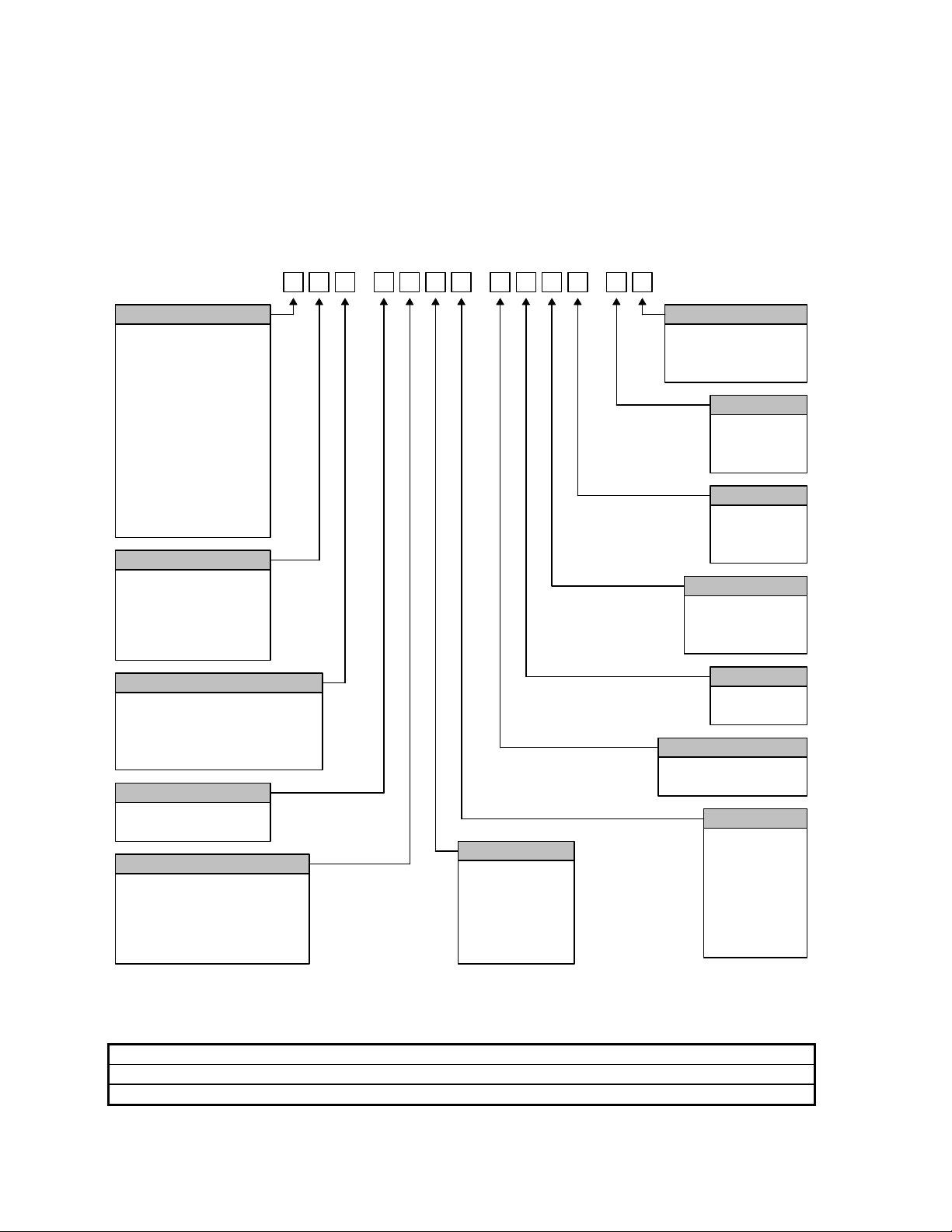
8 Operator’s Manual
Model Numbering System
The control is available with the following hardware and software configurations. Features and control
configuration options in software are based on the I/O configuration of the control. Generally, the
information presented in this guide is based on the I/O configuration as outlined below. Please refer
to your control I/O configuration for available features and product information. The specific
configuration is determined by the Model Number, as shown below:
H
Axis Configuration
2 = 2 Servo Axes
3 = 3 Servo Axes
4 = 4 Servo Axes
5 = 5 Servo Axes
6 = 6 Servo Axes
7 = 7 Servo Axes
8 = 8 Servo Axes
9 = 9 Servo Axes
A = 10 Servo Axes
B = 11 Servo Axes
C = 12 Servo Axes
S = Sercos
I / O Configuration
B = Burny 3 / 5
M = MicroPath
P = PicoPath
V = Voyager
S = Sercos
Power Supplies
0 = Standard Logic Supply
2 = Standard Logic Supply &
Auxiliary Supply with
+5, +/-12 & +24 vdc
Pointing Device
0 = None
1 = Industrial Mouse
LCD Type
X = None
0 = 10.4" Dual Scan DSTN
1 = 10.4" Active Matrix TFT
2 = 15" Active Matrix TFT
3 = 15" Touch Screen
-
Memory
0 = 16 MBytes
1 = 32 MBytes
2 = 64 MBytes
3 = 128 MBytes
4 = 256 MBytes
5 = 512 MBytes
--
Model Numbers
You may wish to record your Model Number in the space provided below.
Model Number Information
Model Number:
Serial Number:
Operating System
0 = Windows 95 / 98
1 = Windows NT
2 = Windows XP
APC
0 = None
1 = 1 APC
2 = 2 APC's
THC
0 = None
1 = 1 THC
2 = 2 THC's
Speed Pots
0 = None
1 = 1 Speed Pot
2 = 2 Speed Pots
Joystick
0 = None
1 = Joystick
Backup Hard Drive
0 = None
1 = Installed
Processor
0 = 166 MHz
1 = 200 MHz
2 = 266 MHz
3 = 433 MHz
4 = 566 MHz
5 = 1.2 GHz
6 = 2.4 GHz
Page 23
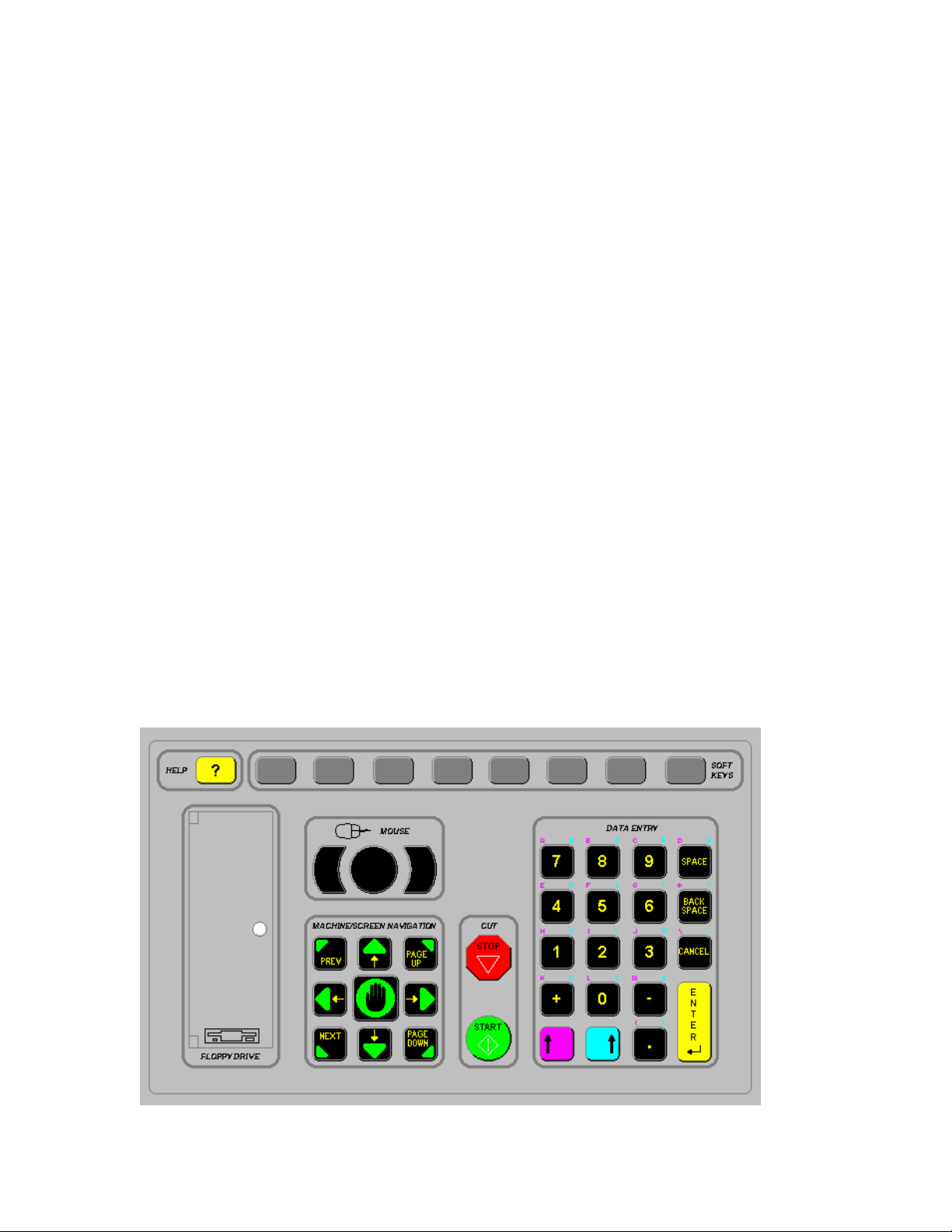
Section 2: Overview 9
Front Panel Layout
The front panel keypad of the control is shown below. In the upper center is the Color LCD display.
The power switch is located in the upper left-hand corner of the front panel. The power switch is
illuminated when in the on position.
Located in the upper half of the control is the View Screen. The View Screen offers a simple to follow
graphical interface for the operator to view all aspects of control operation such as machine setup,
part file management, part programming and cutting operations.
Below the View Screen, there are several groups of push buttons or keys on the front panel. The
eight keys located directly below the display and labeled with Soft-Keys act as programmable keys.
The functions of these keys are shown in the display. This is supported directly on screen for units
with touch screen displays. Softkeys allow many different functions to be included without an
excessive number of separate keys. It also provides complete flexibility for future software features
and enhancements.
The yellow key labeled HELP is for on-line documentation and help. Simply press this key at any
time and this document will be displayed.
The keys to the lower right of the front panel comprise the alpha numeric keypad, which is used for
entering data. To the far left, under the label Machine/Screen Navigation, are keys which control
manual motion and cursor location during data input. These include the MANUAL key (for Manual
Mode jogs) and the eight arrow keys (for jog and cursor direction).
The two keys under the label CUT are for program start and stop.
Behind the small door labeled FLOPPY DRIVE is the internal 3.5” 1.44Mbyte floppy disk drive. In
addition, there is a small potentiometer behind this door to adjust the LCD brightness and contrast for
dual scan displays. This potentiometer should only need to be set once, at the time of installation,
unless the control is being operated in an extreme temperature environment.
Front Panel
Page 24
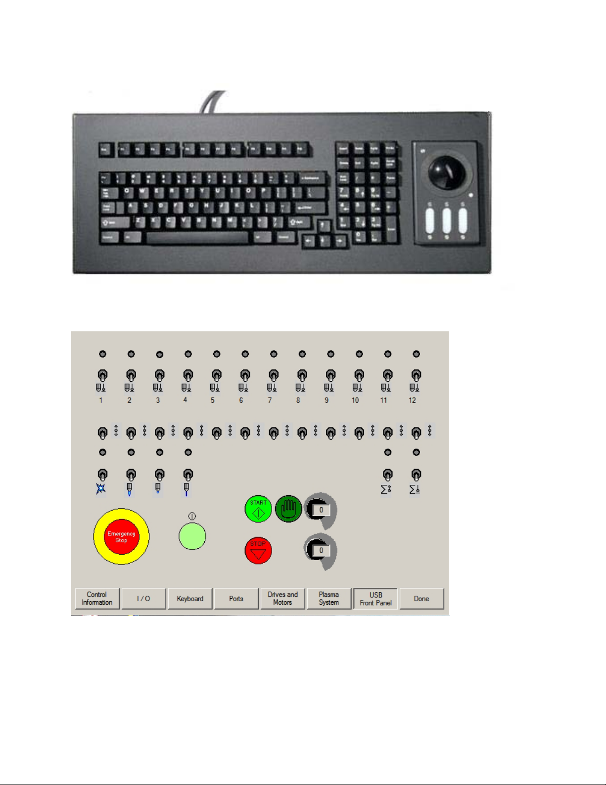
10 Operator’s Manual
Optional PC Style Keyboard
Optional USB Front Panel
Page 25

Section 2: Overview 11
Operation Summary
The programming and operation of the control is menu-driven. The following diagram shows the
Screen Hierarchy for the menu structure.
The menu that appears in the display when the unit is first turned on is referred to throughout this
manual as the Main Menu. All other menus and functions are accessed at some level under Main
Menu, or else appear as part of a special operational sequence, such as when the cutting process is
interrupted during the middle of a part.
The DONE and CANCEL keys have special functions in relation to the menu structure. The DONE
key returns to the menu from which the present selection was entered and retains any changes that
were made. The CANCEL key returns to the menu from which it was entered and deletes/discards
any changes that were made. There are, however, some operations during which CANCEL is not
active.
Screen Hierarchy
Main Screen
Cut
Pause
Change Consumable
Manual Options
Load from Disk
Save to Disk
Save Log to Disk
Download from Host
Upload to Host
Cut Chart
Change Consumable
Manual Options
Manual
Manual Options
Home Axes
Part OptionsFiles
Repeat
Align
Manual Options
Setups
Cut Types Password 1Diagnostics
Oxy Fuel
Timing Diagram
Water Jet
Timing Diagram
Plasma
Timing Diagram
Cut Chart
Marker
Timing Diagram
Cut Chart
Laser
Timing Diagram
Cut Chart
Process Monitoring
Shape Manager
Shape Library
Simple Shape
View Text
Part Options
Repeat
Align
Manual Options
Control Information
I / O
Inputs
Outputs
Analog Inputs
Keyboard
USB Front Panel
Serial Port
Drives and Motors
Plasma System
Inputs
Outputs
Supply Information
Nester
Nester Setups
Load from Disk
Download from Host
Shape Library
Simple Shape
Speeds
Link
I/O
Axes
Transverse
Rail
Dual Gantry
CBH
Tilt
Rotate
THC
Lens
Shape Wizard
Part Options
Repeat
Align
Manual Options
Cutting
WatchMachine
Password 3
Station Configuration
Password 2
System Tools
Backup Hard Drive
Scan Hard Disk
Defrag Hard Disk
Format Floppy Disk
Network Tools
Remote Assistant
NJWin Tools
Text Editor
Teach Trace
HyperCAD
HyperNest
Page 26
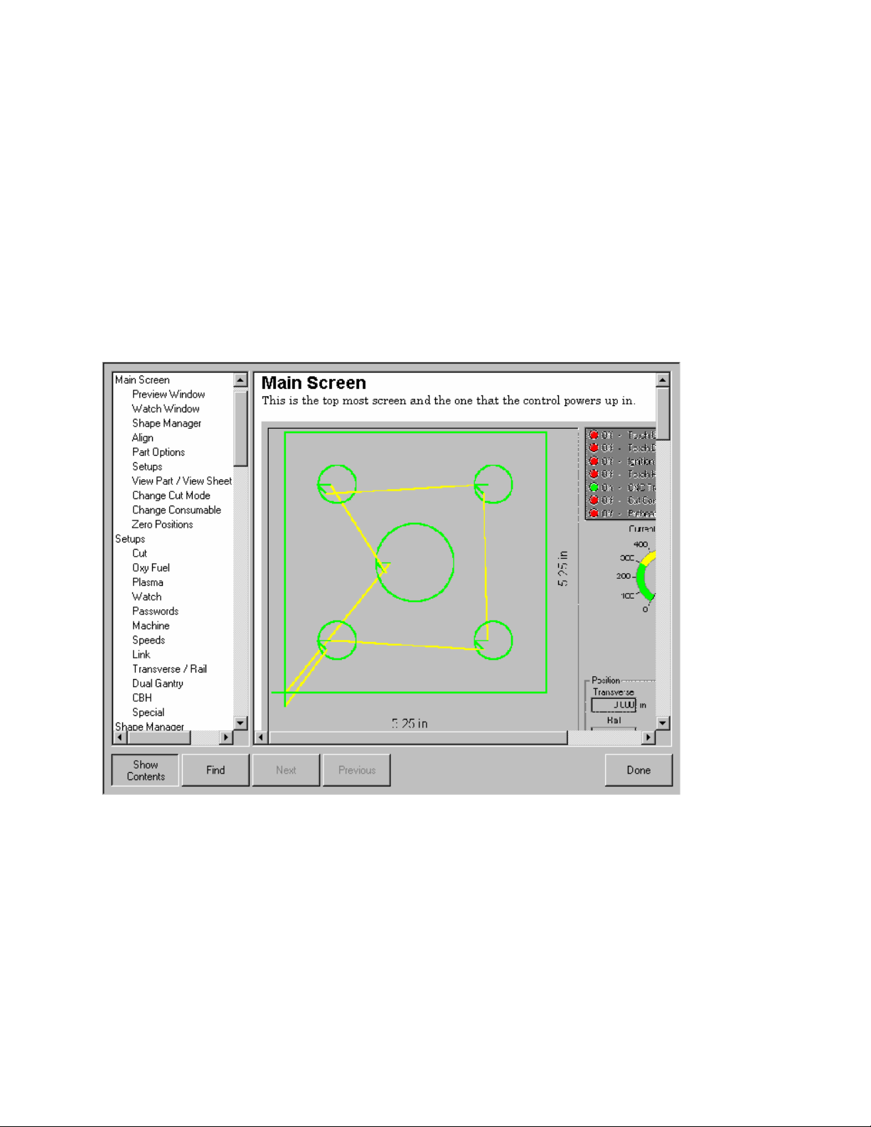
12 Operator’s Manual
Key & Menu Functions
The following is a short form description of all menu functions in the control. This is only a brief
description of each function. Please consult the subsequent manual sections for more complete
information on operational usage of specific keys.
Help Screen
This controller is equipped with an easy to follow help screen function. To access the internal help
screens press the yellow softkey to the top left of the keypad. Help information for the screen
currently being accessed will be displayed. Pressing the DONE softkey will exit the help screens and
return you to the last control screen accessed.
Show Contents
While at the help screen, the table of contents may be turned on and off by pressing the Show
Contents softkey. Use the up/down arrow keys to select a subject and press enter to view.
Press the previous/next key to move from the table of contents and the information screen and back.
While at the information screen, the up/down arrow keys are used to scroll through the information on
the selected topic.
Find
The find feature will search for a requested topic within a selected information screen.
Page 27
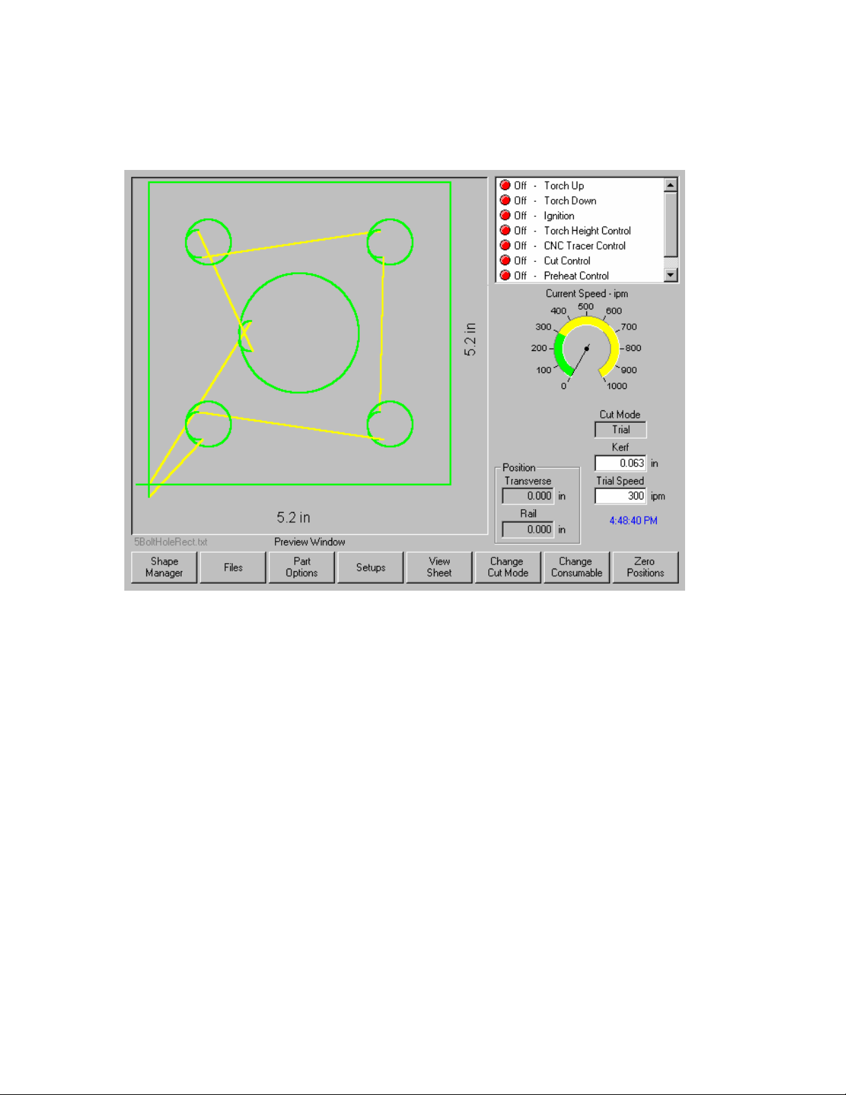
Section 2: Overview 13
Main Screen
This is the top most screen and the one that the control powers up in.
Preview Window
This window displays the current part in memory with the overall dimensions for that part.
Watch Window
This is the right part of the screen where such things as the speedometer, positions, cut mode and
time are displayed. This part of the screen is configurable through the setups. Up to 10 different
Watch Windows are available for viewing during use.
Shape Manager
This softkey takes you to the Shape Manager screen where you can load a simple shape, edit a part
using the text editor or shape wizard or teach trace a part.
Files
This softkey takes you to the Files screen where you can load, save, download or upload part files.
Part Options
This softkey takes you to the Part Options screen where the current part can be scaled, rotated,
mirrored and/or repeated.
Page 28
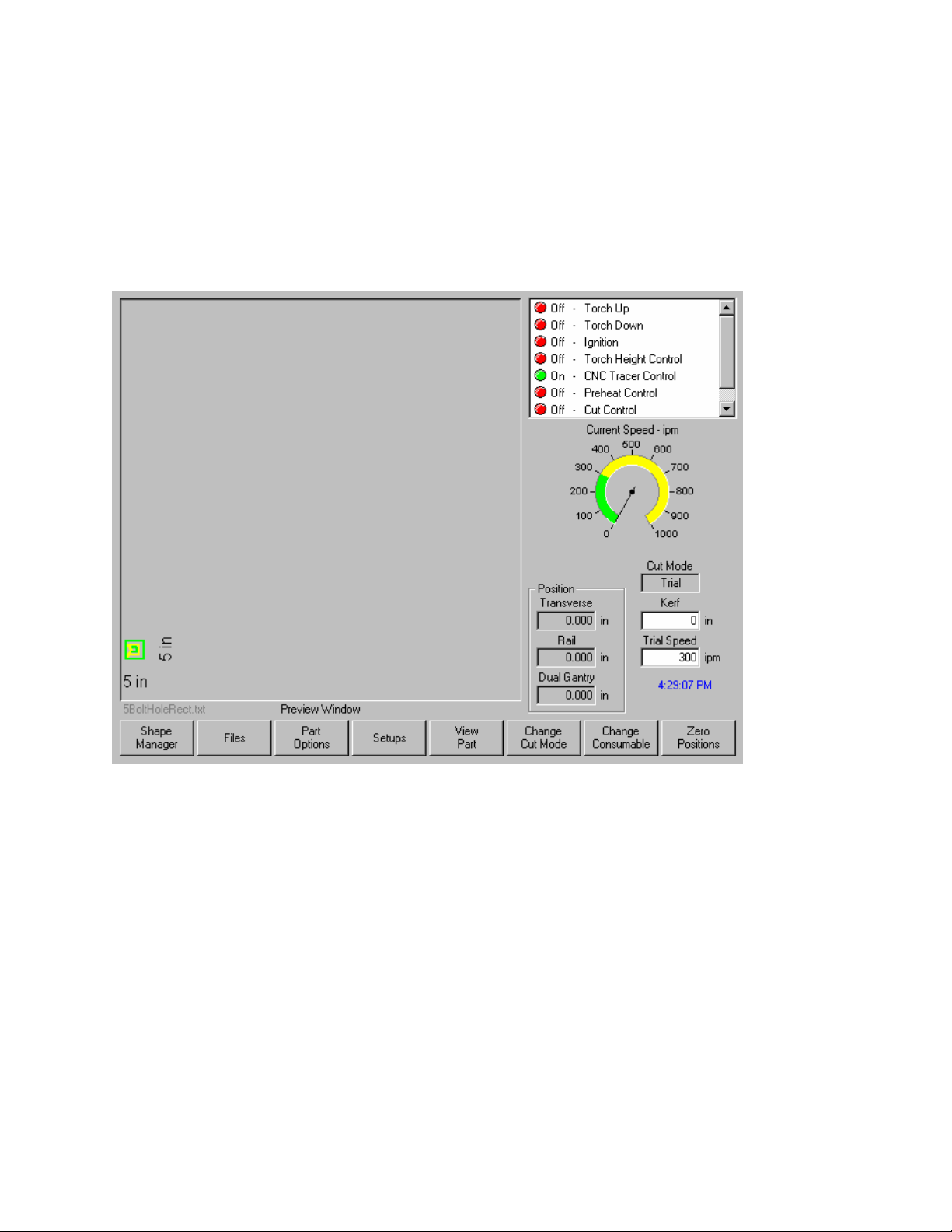
14 Operator’s Manual
Setups
This softkey takes you to the setup screens.
View Part/View Sheet
View Part allows the viewing of the entire current part in the Preview Window.
View Sheet allows the viewing of a part as it would appear on the plate. After pressing the View Sheet
softkey, the display window zooms out to show the part in relationship to the entire plate.
After zooming out, the display can be zoomed in again by pressing the + key, which causes horizontal
and vertical scroll bars to be displayed. Pressing the - key will zoom back out.
Page 29
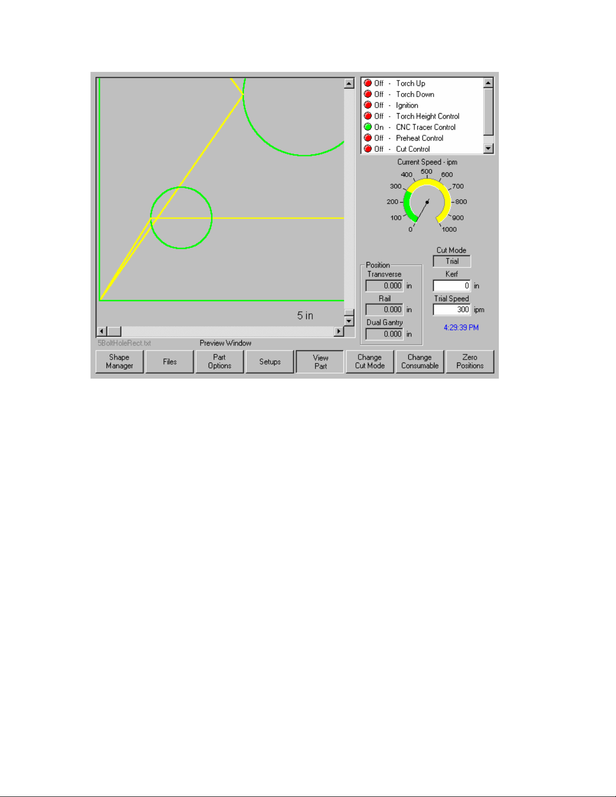
Section 2: Overview 15
While the scroll bars are displayed and the control is not cutting, the view of the plate can be shifted
horizontally and vertically by holding down a shift key and pressing the arrow keys. While the control
is cutting, the view will automatically be shifted as the cut path reaches one of the edges of the view.
This mode is useful in normal cutting to closely follow the cut-path while in zoom.
View Sheet is more useful when proper Plate Size values have been entered in Cutting Setups.
Change Cut Mode
Allows selection of Trial, Oxy Fuel, Plasma, Waterjet and Laser cutting modes, depending on the
setup configuration. This softkey offers the selections of Automatic, Manual or Test Run for I/O type
“B” configured controls.
Change Consumable
This softkey takes you to the Change Consumable screen.
Zero Positions
This softkey zeros the current positions on the Transverse and Rail axes as well as the Dual Gantry
axis if used.
Page 30
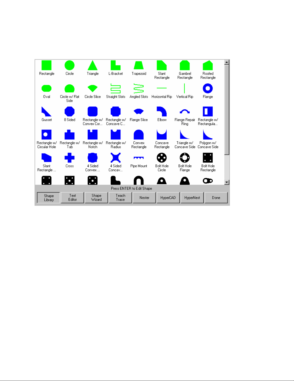
16 Operator’s Manual
Shape Manager Screen
The Shape Manager screen is used to retrieve a part from the Shape Library and edit part files.
Shape Library
Brings up the built-in library of 53 simple shapes.
Text Editor
Enters the full screen ASCII text editor. The current part in memory is loaded, allowing direct editing
of the selected part program.
Shape Wizard
Enters into the ShapeWizard
selected part program using an easy to use graphical interface to view changes as they are made.
Teach Trace
Enters the trace-teach menu, where with an optional tracing system, you can digitize a template.
Nester
Nester™ is a proprietary part nesting program which allows the operator to manually group or nest
selected parts together as one part program to conserve raw materials and maximize machine
utilization.
An optional Automatic Nesting feature is available as an add-on item to Nester™. This true shape,
single station, automatic nesting package allows quick and simple nesting of profiles on to selected
material sizes. This feature is offered as a limited use trial version. Please contact your control
vendor for information on adding this feature.
®
a graphical editor window. ShapeWizard® allows direct editing of the
Page 31

Section 2: Overview 17
HyperCAD
The optional HyperCAD
®
feature is an easy to use 2D drawing application specifically designed for
shape cutting. The software’s powerful CAD utilities let users import DXF and CNC files or draw from
scratch. Files can be converted to graphical parts for editing and saving or go directly to cutting.
HyperNEST
The optional HyperNEST
allow quick and simple nesting of profiles onto standard material sizes. With its advanced Graphical
User Interface, HyperNEST
®
feature is a full featured, automatic true shape application designed to
®
greatly improves the output of any shape cutting operation.
Evaluation Timer
Trail version software will prompt the user with a notification of the number of “uses” left at each
launch. To enable unlimited use, a password would be provided by the control vendor.
To launch the trial software, select the Evaluation Version.
Example:
Page 32
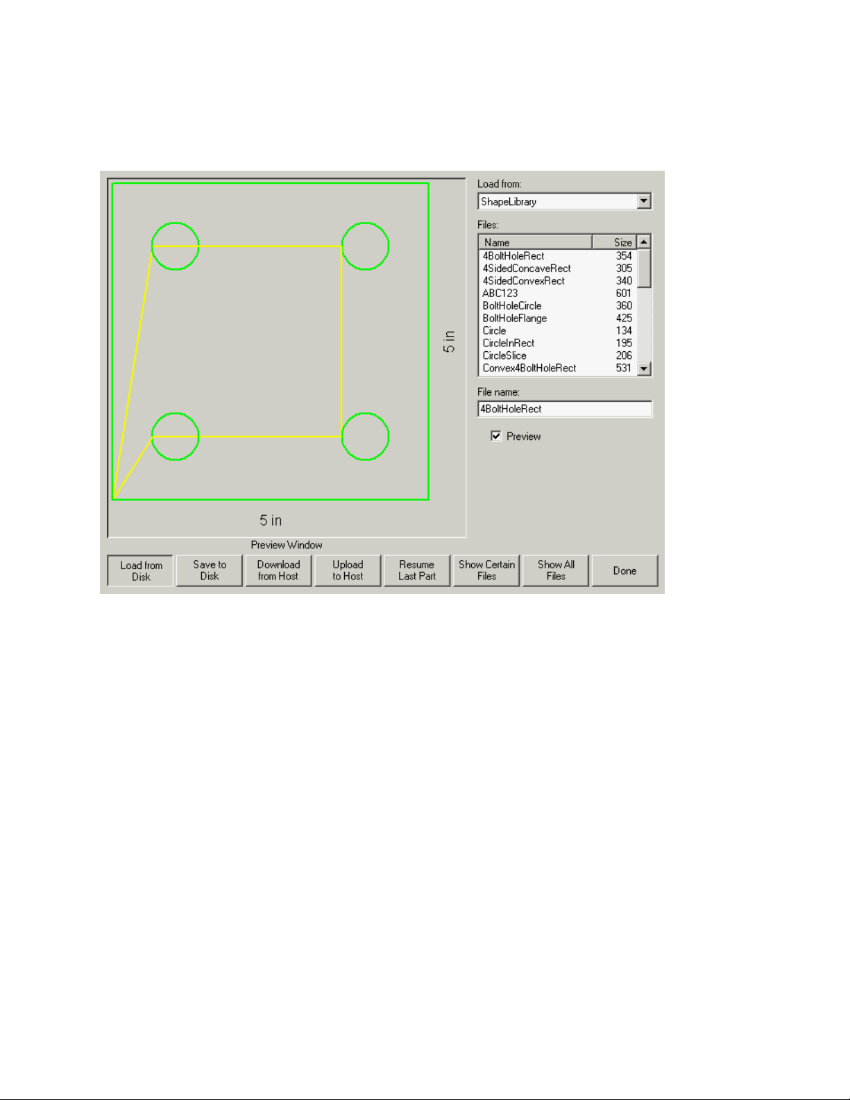
18 Operator’s Manual
Files
From the Files screen the user may load or save parts on the control or an external location.
Load from Disk
Allows programs to be loaded from the internal disk drives or external mapped drives (network option)
into working memory.
Save to Disk
Allows the current program in memory to be saved to the internal disk drives or external mapped
drives ( network option ). This also accesses the Save Key Logging File screen.
Download from Host
Allows programs to be downloaded from a host computer to the internal disk drives over the selected
RS-232C/ RS-422 serial port.
Upload to Host
Allows programs from the internal disk drives to be uploaded to a host computer via the selected RS232C/RS-422 serial port.
Resume Last Part
The Resume Last Part softkey will be visible when the Rush Job Interrupt or Automated Power Loss
Recovery feature is in use. These features allow the user to pause the current part program and
retain the part and current position information. This then allows the user to load and execute
another part program and return to the original part using the Resume Last Part softkey.
Page 33

Section 2: Overview 19
Show Certain Files
This softkey allows the operator to show only certain files from the selected directory. Both the
asterisk and question mark may be used in defining the files to show. The asterisk is generated by
holding down the left shift key and pressing the backspace key. The question mark is generated by
holding down the right shift key and pressing the backspace key.
Show All Files
This softkey allows the operator to undo the Show Certain Files from above.
Note: An optional Network Card for connecting directly to a PC Network for part file allocation is
available.
Page 34
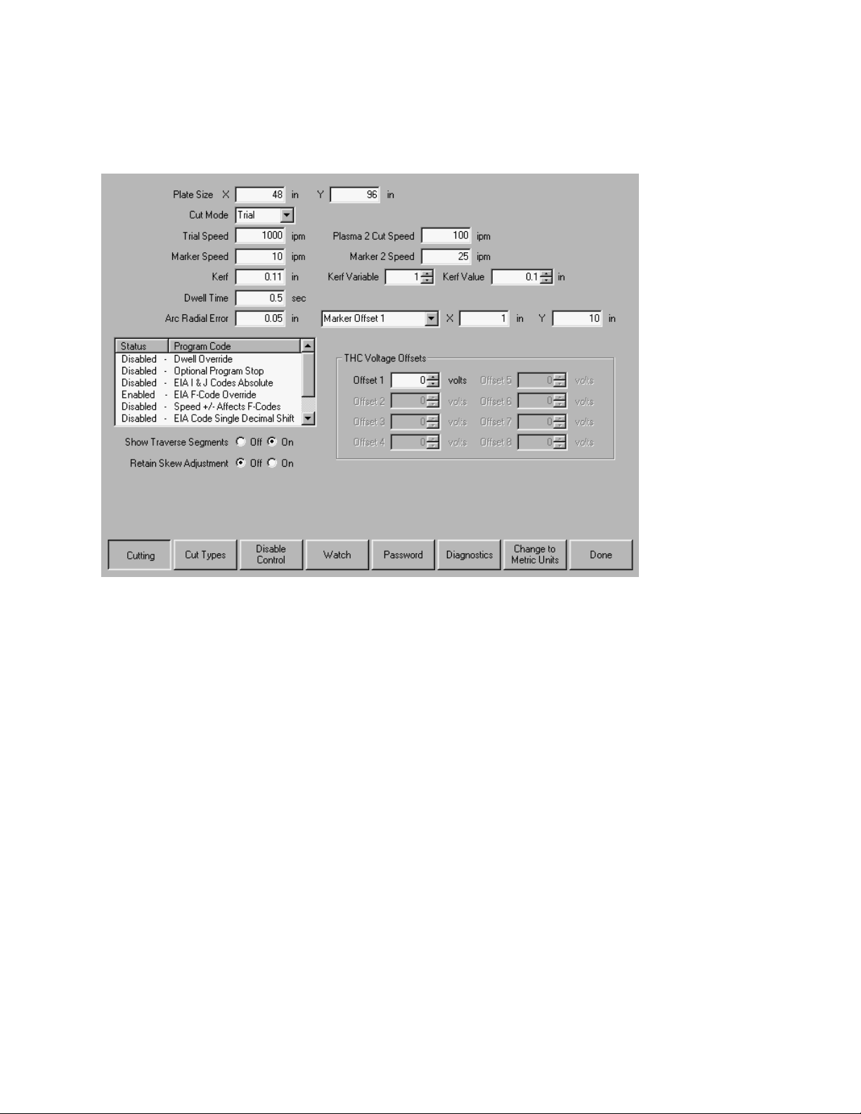
20 Operator’s Manual
Setups Screen
The Setups Screen is used to configure the control for use.
Cutting
Allows programming of the different cutting parameters EIA program types, dwell times, etc.
Cut Types
Enters the cut type menu, which allows editing of gas control sequencing variables for oxy-fuel and
plasma cutting.
Disable Control
Pressing the Disable Control softkey disables the motion command from the control to the drive
system. While disabled, I/O points and encoder feedback are still active.
Watch
Allows programming of the user definable Watch Window.
Password
Enter a password to get to the supervisor password protected setup menu.
Diagnostic
Enters the diagnostics menu.
Change to Metric Units/English Units
Changes all parameters over to metric units or English units.
Page 35
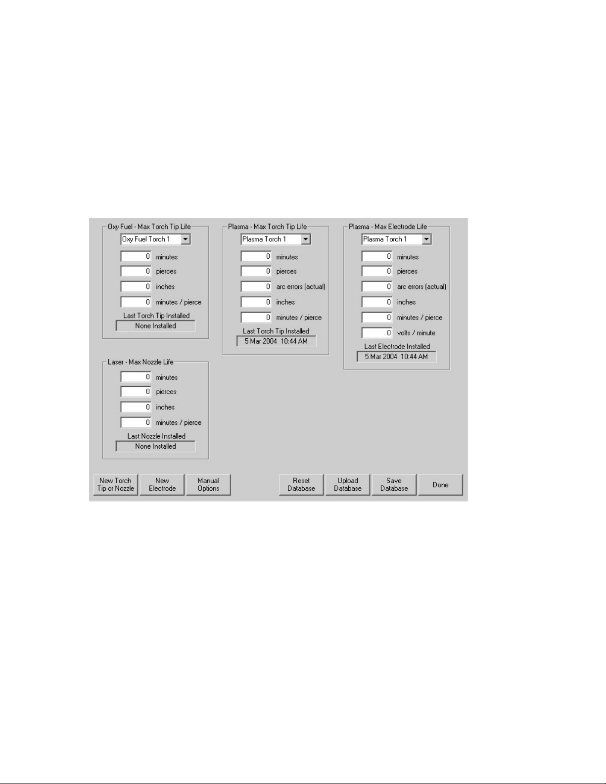
Section 2: Overview 21
Change Consumable
The Change Consumable Screen is used to track and record consumable life in a database. If the
New Torch Tip or New Electrode softkey is pressed every time a torch tip or electrode is changed, the
last information for the corresponding consumable will be added to a database. This database will
show the date a consumable was changed and how long it lasted in minutes, pierces, inches /
millimeters of travel and Arc Errors. Torch Tip and Electrode data can be recorded for up to twelve
Oxy torches and up to eight plasma torches. A special feature allows the user to add an additional
wear factor ( in minutes ) to compensate the database for the additional wear during piercing.
Additionally, a Change Consumable Output will be activated when the specified limit has been
reached. This output may be tied to an indicator lamp or alarm to prompt the operator to change the
consumable.
New Torch Tip
This softkey records when a new Oxy Fuel or Plasma torch tip has been installed on the machine.
New Electrode
This softkey tells the control that a new electrode had been installed on the cutting machine.
Reset Database
This softkey is used to reset the database on the control to have no torch tip or electrode information.
Setups
Pressing the Setups softkey access the control setups for adjustment of the cut process.
Upload Database
This softkey is used to upload the current database to a host computer running our link.
Save Database
This softkey is used to save the current database to the diskette.
Page 36
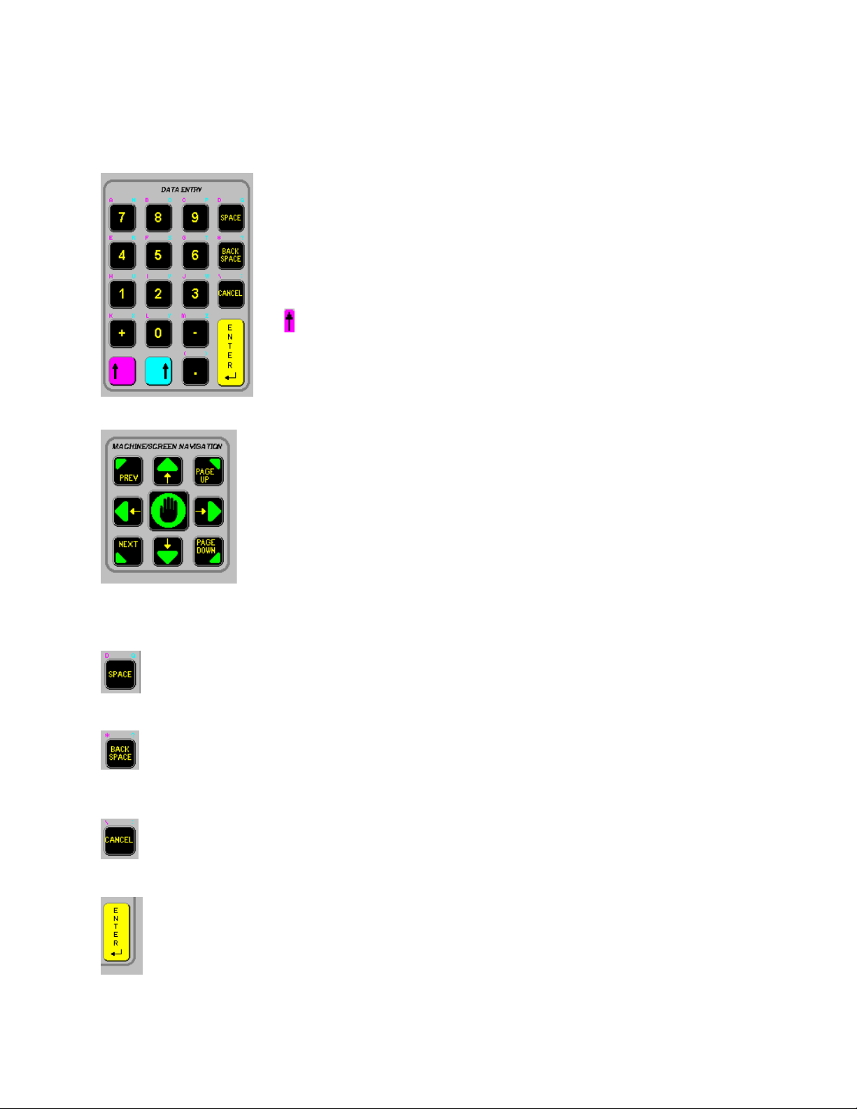
22 Operator’s Manual
g
A
Key Functions
The alpha–numeric keypad is used to enter numeric data or text.
To enter a number, simply press the key. To enter a word, press
and hold the matching colored shift key (up arrow) while pressing
the desired letter key. The + (plus) and – (minus) keys are used to
add and delete features at selection and check boxes.
purple or blue arrow at the left or right edge of the softkeys
indicates that that more softkeys and features are available by
pressing the corresponding shift key on the alpha-numeric
keypad.
Pressing the space key inserts a space into the current data entry field. The space key
is also used to toggle between fixed logic settings ( i.e. setups - preheat sense input
open/closed ). The space key may also be used to add and delete features at selection
and check boxes.
Deletes the current character in the data entry field and backs up one position in the
field. Located above the Back Space key are the * and ? characters which are used as
These keys activate jogging using the arrow keys when in the
manual mode. Manual key functions (indicated in green) are
available at the Manual, Pause and Align Screens. This keypad is
also used for navigating through a multi-variable dialog box
(indicated in yellow).
The Prev/Next buttons are used to move through the field boxes,
Page Up/Down is used to scroll and the arrow keys are used to
select items in a dialo
box.
Can be pressed at any time (except during cut) to return to the previous menu
without saving any changes. Located above the Cancel key are the \ and :
characters which are used for mapping network drives.
Causes the last number entered/toggled to be accepted. Located above the enter
key are the < and > characters which are used for mapping network drives.
Page 37

Section 2: Overview 23
Optional PC Keyboard Layout
Keyboard Functions
Function Keys F1-F8 are equivalent to the soft keys on the display screen.
Function Key F9 is equivalent to the START key.
Function Key F10 and Pause Key are equivalent to the STOP key.
Function Key F11 is equivalent to the MANUAL MODE key.
Function Key F12 is equivalent to the HELP key.
Arrow direction keys are used for manual motion.
The HOME key is equivalent to the PREV field key.
The END key is equivalent to the NEXT field key.
The [ key is equivalent to the purple arrow shift key.
The ] key is equivalent to the blue arrow shift key.
The Esc key is equivalent to the CANCEL key.
To exit the control software press Alt F4. Warning: This will terminate the current application.
To switch between applications press Alt Tab. Warning: The selected application window to be on
top of the desktop and may cover or hide the control software application window.
Page 38
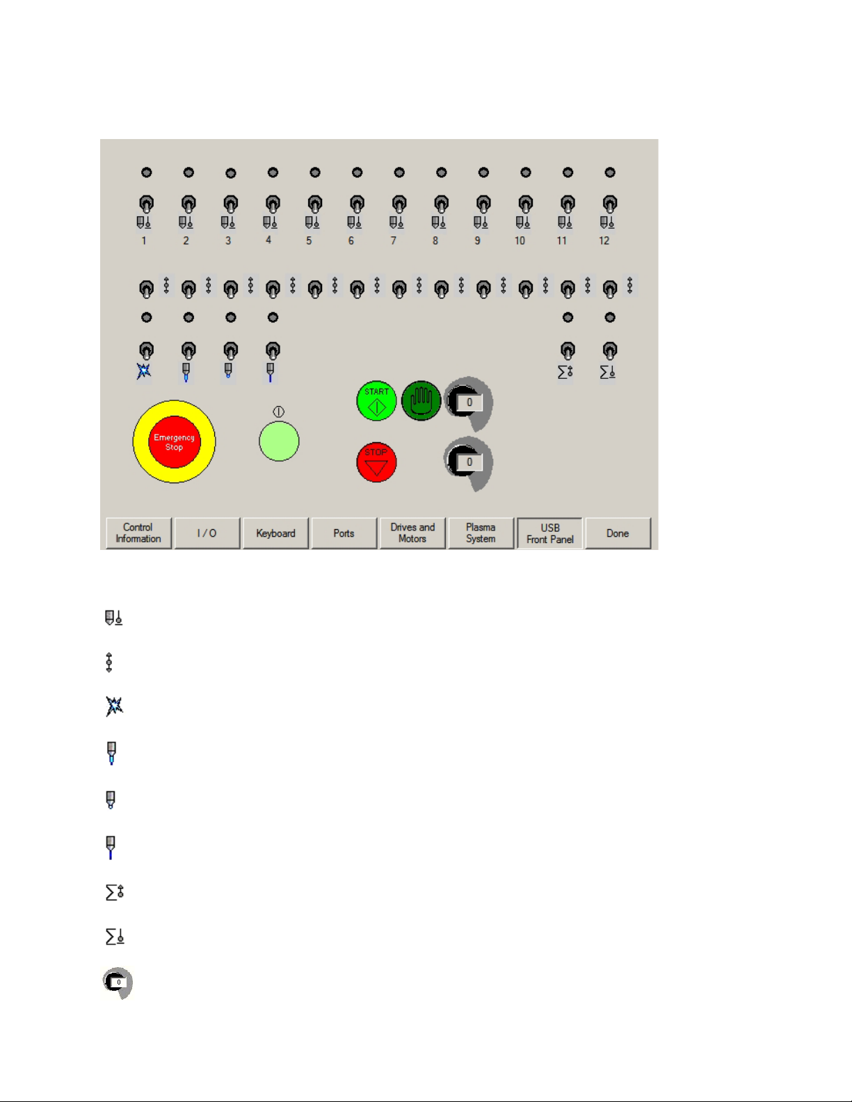
24 Operator’s Manual
Optional USB Front Panel
ICON Legend
Single station torch selection. Upper switch position is automatic operation. Center switch
position is OFF. Lower switch position is manual operation.
Manual Raise and Lower of selected station.
Manual ignition of torch.
Manual High Preheat.
Manual Low Preheat
Manual Cut Oxygen
All stations UP.
Automatic plate sensing (IHS) for pre-selected stations
Speed Pot
Page 39

Section 3: Setups 25
Section 3: Setups
Cutting
When entering the Setup menu the operator will be prompted for the following run-time parameters
for Trial Mode (no cutting), Oxy-Fuel, Plasma Waterjet and Laser cutting.
Plate Size
Specifies the dimensions of the current plate being cut. This dimension is used when loading a part
to determine if it will fit on the plate. It is also used for viewing the part in Screen View.
Cut Mode
Specifies the current cut mode. Trial/Test mode allows the operator to dry-run the current part
program without cutting. Press the left or right arrow keys to select the desired cut mode.
Trial/Cut Speed
Specifies the speed for the current cut mode. These speeds are saved independently for trialing and
cutting. Both speeds will be limited to the maximum machine speed. Cut and Trial speeds may be
executed at the embedded F-code speed within a part program.
Marker 1 / Marker 2 Speed
Specifies the speed for the selected Marker. These speeds are saved independently for each Marker
and are executed through the marker tool selection within a part program. Marker 1 is activated by
EIA RS-274D M09 and M10, or an ESSI 9 and 10. Marker 2 is activated by EIA RS-274D M013 and
M14, or an ESSI 13 and 14.
Page 40

26 Operator’s Manual
Kerf
Specifies the amount of kerf (cutter compensation) that will be applied to the current part program.
Care should be taken when selecting a kerf value as this parameter can cause invalid geometries to
be generated. For example, adding a kerf of 0.5” to an arc with a radius of 0.25”. After entering a
kerf value, the kerf compensated cut path can be viewed by pressing the Kerf softkey under the Part
Options menu.
Dwell Time
Specifies the amount of dwell (delay) to be inserted into the current part program when an
appropriate RS-274D program block is reached. This time can be overridden in the part program.
For example in EIA programming a G04 X3 will cause a three second dwell to be inserted at the
current program block. A G04 with no X-code will insert a dwell with the current Dwell Time
parameter.
Arc Radial Error
Specifies the arc error tolerance to be used when checking the current segment for dimensional
accuracy. All ESSI or EIA programs are comprised of lines, arcs, and circles. Arc Radial Error is
used to make sure that the starting and ending radial vectors are within tolerance to describe a valid
geometry.
Dwell Override
When this parameter is enabled, embedded dwell G04 Xvalue codes in an RS-274D program will
override the operator entered dwell time.
Optional Program Stop
Allows overriding of the optional program stop code M01 in the current part program. If enabled, an
M01 code operates identically to M00. If disabled, the M01 code is ignored.
EIA I & J Codes
Selects Absolute or Incremental RS-274D programming mode. In Incremental mode, all offsets for X,
Y, I and J relative to the current block. In absolute, mode all X, Y, I and J are relative to an absolute
reference point unless changed by using a G92 program code.
EIA F-Code Override
When this parameter is enabled, embedded F-codes in an RS-274D program will override any
operator entered Cut Speed.
Speed +/- Affects F-Codes
When this parameter is enabled, the control will apply the speed increase/decrease percentage to all
embedded F-codes encountered in the part program
EIA Decimal Shift
Some programming styles are structured so that the decimal point in the EIA positioning affecting part
sizing is assumed. The EIA decimal shift parameter allows the operator to select the location of the
decimal point when translating parts by selecting normal or single for correct translation. The
selection should be set to Normal unless your part programs have only a single digit to the right of the
decimal point.
Process Select Override
When enabled, this feature will allow the part program to override the process select input.
Station Select Override
When enabled, this feature will allow the part program to override the currently selected station select
input.
Page 41

Section 3: Setups 27
Auto Torch Spacing Override
When enabled, this feature will allow the part program to override the manually selected Torch
Spacing inputs.
G97 Loop Count Prompt
When Enabled this feature will post a message on the screen to enter the number of loops or repeats
to be selected when an EIA G97 code without a “T” value is encountered in the part program.
ESAB Multi Torch Support
When enabled this feature allows ESAB style ESSI part programs to map codes to specific station
selects.
Mapped
ESSI CODE
EIA CODE Description
7 M37 T1 Select Station 1
8 M38 T1 Deselect Station 1
13 M37 T2 Select Station 2
14 M37 T2 Deselect Station 2
15 M37 T3 Select Station 3
16 M38 T3 Deselect Station 3
Force G40 Kerf Disable
In a part program Kerf is enabled and disabled using EIA G41/ G42 and G40 codes. Standard
operation is to disable Kerf at the cut off even if the G40 Kerf Disable is not in a program. With this
parameter, you can select to turn off the “forced” G40 Kerf Disable if no g40 is used in the program by
setting the parameter to a “Disable” state.
G40 Used in Simple Shapes
Used in conjunction with the Force Kerf Disable parameter this allows the G40 code normally inserted
in to a Simple Shape from the control Shape library to be omitted by setting the parameter to a
“Disable” state.
Auto Start after APA
Used with the Automatic Plate Alignment feature, this allows to user to select to automatically begin
cutting after completion of the Automatic Plate Alignment.
EIA Code 2 Decimal Shift
Some programming styles are structured so that the decimal point in the EIA positioning affecting part
sizing is assumed. The EIA Code 2 Decimal Shift parameter allows the operator to select the location
of the decimal point when translating parts by selecting normal or single for correct translation. The
selection should be set to Normal unless your part programs require two decimal shift to the right of
the decimal point.
Show Traverse Segments
Allows traverse segment lines (displayed in yellow) to be turned OFF or ON during all part preview
displays.
Retain Skew Adjustment
The Retain Skew Adjustment feature is used to retain the last calculated plate skew for all
subsequent parts that are loaded. If disabled any new part that is loaded will remove any previously
calculated plate skew.
Kerf Variable / Kerf Offset
Page 42

28 Operator’s Manual
The Kerf Variable / Kerf Offset parameter is used to create a Kerf Variable table which assigns a
reference number (variable) to a Kerf value. Up to 200 variables may be entered to create a
reference table.
This Kerf Variable can then be used within a part program to define the kerf value when cutting. The
advantage to this is that as torch parts wear, the kerf value changes. If the Kerf Variable value is
updated as the consumable wears and changes, the new value will be called by the Kerf Variable
command with all programs loaded that use the variable.
The EIA-274D part code for left kerf variable is the G43 code.
Example: G43
D1 X0.06
Kerf Variable Setting
Kerf Variable
A number from 1-200 may be used
Kerf Data
The selected kerf value
Marker Offsets 1 - 12
Enter in values for up to twelve programmable marker offsets. The machine is offset by this amount at
maximum speed when the appropriate marker code is detected.
THC Voltage Offset
The THC Voltage Offset parameter is used to offset the individual Sensor THC™ Arc Voltages from
the master set Arc Voltage. This allows the individual THCs to be adjusted to compensate for
consumable wear and obtain optimum cut quality.
Marker On Time (Type “B” Configuration Only)
This parameter allows the operator to insert a time delay, which allows the marker to prepare for
operation prior to the start of Marker motion.
Marker Off Time (Type “B” Configuration Only)
This parameter allows the operator to insert a time delay, which allows the marker to complete
operation at the end of Marker motion.
Page 43

Section 3: Setups 29
Cut Types
Your shape cutting control comes standard with several styles of built-in cut process logic which
allows the cut process timing to be configured for optimum performance. Selection will vary due to
control configuration.
Example:
In the Plasma Cut Type example provided above, various process timing adjustments may be made
to tune the process to the Plasma System and material being cut for the desired performance.
Pressing the space key allows the user to view a graphical diagram of the process logic
Additionally, each cut type has the ability to save and load the process setups in a file on the hard
drive or to a floppy diskette. The Purple arrow at the left edge of the softkeys indicates additional
softkeys are available. Pressing the shift key allows the Save Data and Load Data functions to be
available.
Page 44

30 Operator’s Manual
Oxy Fuel
The control comes with the following built-in control logic for Oxy Fuel cutting. When Oxy Fuel is
selected, the following parameters are available to customize the logic for the particular metal being
cut. As these parameters are changed, the timing diagram below will change to show the new timing
parameters. This screen is located under the Cut Types softkey in the Setups.
Note: Pressing the Start key twice will bypass all timers and begin the cut.
I/O Configuration Type “M”, “P” and “V”
I/O Configuration Type “M”, “P” and “V”
Press the Space Key to view the timing diagram from setups.
Page 45

Section 3: Setups 31
I/O Configuration Type “B”
I/O Configuration Type “B” (Timing Diagram)
Press the Space Key to view the timing diagram from Setups.
Ignition Time
Specifies the length of time that the oxy fuel igniter is held on at each ignition of the flame.
Low Preheat
For those cutting systems that are equipped with a Low Preheat feature, this parameter allows the
operator to input a timing delay to activate the Low Preheat output prior to the High Preheat.
Page 46

32 Operator’s Manual
High Preheat
Specifies the length of time to wait at each pierce position for preheating the piece prior to piercing.
During the run-time, the operator may use the SET, EXTEND, or RELEASE softkeys to customize the
preheat length for the particular metal being cut.
Pierce Time
Specifies the amount of delay after the cutting gas is turned on before lowering the torch to the cut
position.
Moving Pierce Time
The Moving Pierce Time parameter specifies the amount of time that the Pierce Output remains on
while piercing with motion.
Creep Time
Specifies the amount of time after piercing the part that the torch travels at Creep Speed. Creep
Speed is determined by a setup parameter at the Speeds setup screen and is a percentage of the
programmed cut speed. After the Creep Time is completed, the control accelerates to full cut speed.
This parameter is helpful in allowing the operator to bring the cutting surface up to temperature and
completely pierce the metal before cutting at full speed.
Primary Torch Up Time
Specifies the amount of time used for torch lift after completing each cut. This is normally used to
provide torch head clearance and return the torch to its predefined rest position.
Primary Torch Down Time
Specifies the amount of time used to lower the torch at the beginning of each new cut. This is usually
longer than the Pierce Torch Down Time as it involves lowering the torch from its predefined rest
position.
Pierce Torch Up Time
Specifies the amount of time used for torch lift during piercing. This parameter is used to provide
distance between the torch tip and metal surface for cutting.
Pierce Torch Down Time
Specifies the amount of time used for torch lowering during piercing.
Cut Off Time
The Cut Off delay parameter species the amount of time the cut on output will remain on at the end of
a cut.
Bleedoff Time
Specifies the amount of time that the cut torch will pause to purge the oxygen at the end of a cut
segment before traversing to the next cut segment.
Igniters
When “No” is selected, this feature will turn the Preheat on between cut segments. This is to keep
the torch light for those cutting systems that do not have automatic torch igniters. For those cutting
systems which have automatic torch igniters or that control the torch gases outside of the control, set
this parameter to “Yes”. This tells the control not to turn on the Preheat between cut segments.
Preheat During Cut
Specifies whether the Preheat will be left on while cutting.
Page 47

Section 3: Setups 33
Plasma
The control comes with the following built in control logic for Plasma cutting. When Plasma is
selected, the following parameters are available to customize the logic for the particular metal being
cut. As these parameters are changed, the timing diagram below will change to show the new timing
parameters.
I/O Configuration Type “M”, “P” and “V”
I/O Configuration Type “M”, “P” and “V” (Timing Diagram)
Press the Space key to view the timing diagram from setups.
Page 48
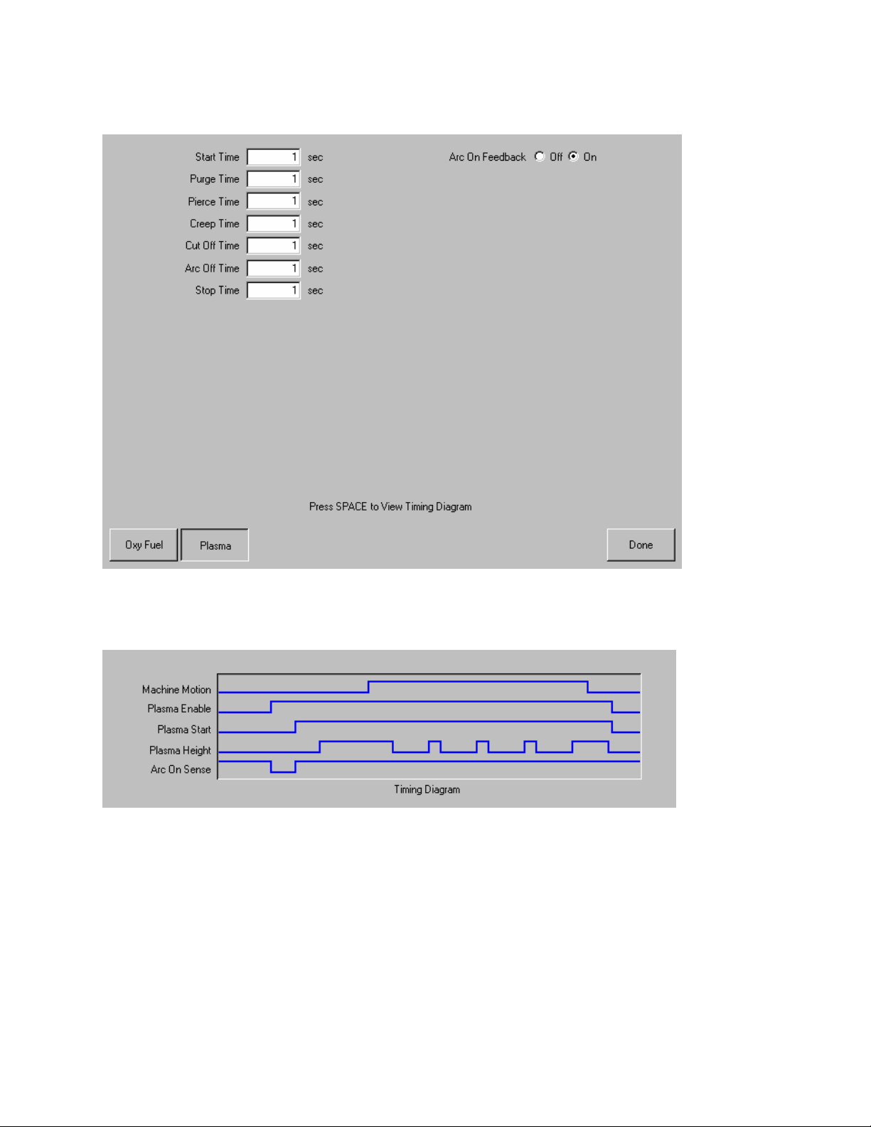
34 Operator’s Manual
I/O Configuration Type “B”
I/O Configuration Type “B” (Timing Diagram)
Press the Space key to view the timing diagram from Setups.
Start Time (Type “B” Configuration Only)
The Start Time parameter is used to delay motion along the cut path when a tool is started or a tool is
lowered.
Purge Time
Specifies the time delay from torch ignition until motion is enabled if Arc On Feedback is OFF. Purge
Time should be set to zero if Arc On Feedback is ON.
Pierce Time
Specifies the time delay from when the torch completes lowering until motion is initiated at Creep
Speed. Used to allow the plasma torch to completely pierce the material before moving.
Page 49

Section 3: Setups 35
Creep Time
Specifies the amount of time after piercing the part that the torch travels at Creep Speed. Creep
Speed is determined by a setup parameter at the Speeds setup screen and is a percentage of the
programmed cut speed. After the Creep Time is completed, the control accelerates to full cut speed.
Cut Off Time
The Cut Off delay parameter species the amount of time the cut on output will remain on at the end of
a cut. A negative Cut Off time up to one second may be used to terminate the cut output prior to the
end of the cut segment. This is used to compensate for response delays of the cut gases that will
maintain the cut arc and widen the cut path at the end of the cut segment.
Full Torch Up Time
Specifies the length of time to raise the torch at the beginning and end of each cut to provide
clearance over the cut pieces. If you are using an automatic height control system, set Torch Up
Time to zero.
Partial Torch Up Time
Specifies the length of time for a partial raise of the torch at the beginning and end of each cut to
provide clearance over the cut pieces. If you are using an automatic height control system, set Torch
Up Time to zero. Note: The Partial Raise parameter must be enabled.
Torch Down Time
Specifies the length of time to lower the torch at the beginning of each cutting cycle. If you are using
an automatic height control system, set Torch Down Time to zero.
Arc Off Time
Specifies the amount of delay to allow prior to indicating a lost cut signal. This can be useful in
helping to minimize nuisance trips when traveling over previously cut paths in complex nested parts.
Stop Time
Specifies the amount of time that X/Y motion will pause at the end of a cut. This pause is
advantageous for allowing the torch to completely raise and clear any cut irregularities before
continuing to the next cut segment.
Retract Delay
Retract Delay specifies the amount of time X/Y and lifter motion will pause at the end of a cut. This
allows the cut process to finish before lifting the torch and moving to the next pierce.
Set Arc Current
The Set Arc Current feature allows the user to set the arc current at the plasma supply. This feature
uses the “Set Current BCD” output from the control to activate the BCD inputs at the plasma supply.
The Set Arc Current parameter is also available for the HD4070
®
via the serial link. EIA RS-274D part
program code G59 Vvalue Fvalue for setting current is supported.
Corner Current Percent
The Corner Current Percent feature allows the operator to select a reduced current setting to be
executed when cutting corners to improve cut quality. This value is a percentage of the Set Current (
above ) and is active when the Torch Height Disable Output is on. The Corner Current parameter is
also available for the HD4070
®
via the serial link.
Retry Transfer Fail
The Retry On Transfer Fail feature is used to specify the number of times the control will attempt to
fire the torch in the event that the torch fails to ignite.
Page 50

36 Operator’s Manual
Transfer Time
The Transfer Time parameter specifies the amount of time used to attempt ignition of the torch. The
ignition is confirmed by the Arc Sense Input (Arc on Feedback) to the control.
Arc on Feedback
Specifies whether an arc-on (also called Plasma Go, Current Sense, Arc Transferred) signal from the
plasma system to the control is used. With Arc On Feedback ON, the control waits for Cut Sense
input to activate before initiating machine motion.
Ignition
Enables use of the Ignition output for use in igniting the plasma torch. If your plasma system requires
a separate ignition signal, toggle Ignition to ON. If not, leave Ignition OFF.
Dual Grid/THC
The Dual Grid parameter enables use of the Torch Height Disable output. This output is used to
disable an automatic torch height sensor or reduce the plasma current in a switchable current plasma
system when machine speed is less than Plasma Hi/Lo Speed.
Dual Grid/THC Start
If Dual Grid is ON, the start mode can be configured to start (HI) or (LOW) at ignition time. For
switchable plasma systems, this usually means that in low mode the plasma system will only deliver
50% of the maximum output power.
Partial Raise
Enabling the Partial Raise feature will execute a tool raise at the end of the cut segment within a nest
for the time specified in the Partial Up Time parameter. Full raise will be executed at the end of the
final cut segment.
Torch Down During Cut
Turning on the Torch Down During Cut feature forces the torch down output to remain on throughout
the cut process. This is advantageous for pneumatic style torch lifters that require a constant output.
Torch Down Between Cuts
Turning on the Torch Down Between Cuts feature forces the Torch Down Output to remain on while
traversing between cut segments.
Page 51
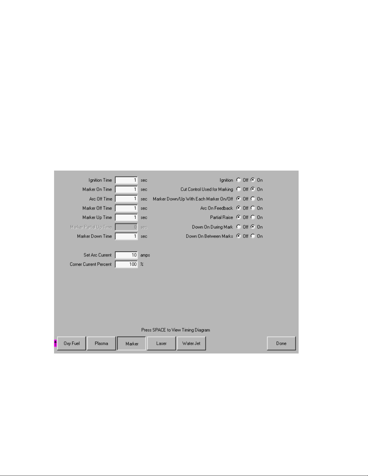
Section 3: Setups 37
Marker
The control comes with the following built in marker control logic for marking. When marking is
selected, the following parameters are available to customize the logic for the particular metal being
marked. As these parameters are changed, the timing diagram below will change to show the new
timing parameters. This screen is located under the Cut Types softkey in Setups.
Note: This screen feature is not available with type “B” configured controls.
Marker Interface
The Marking feature from the control is operated through the use of existing I/O points for cutting
torches on the control I/O connector. These I/O points may be switched from the cutting torch to the
marking tool by use of an external relay(s) activated by the Marker Output or the Marker Output may
be used to activate the marking tool.
Please refer to the Machine Interface section of this guide for exact I/O pinout information.
Page 52
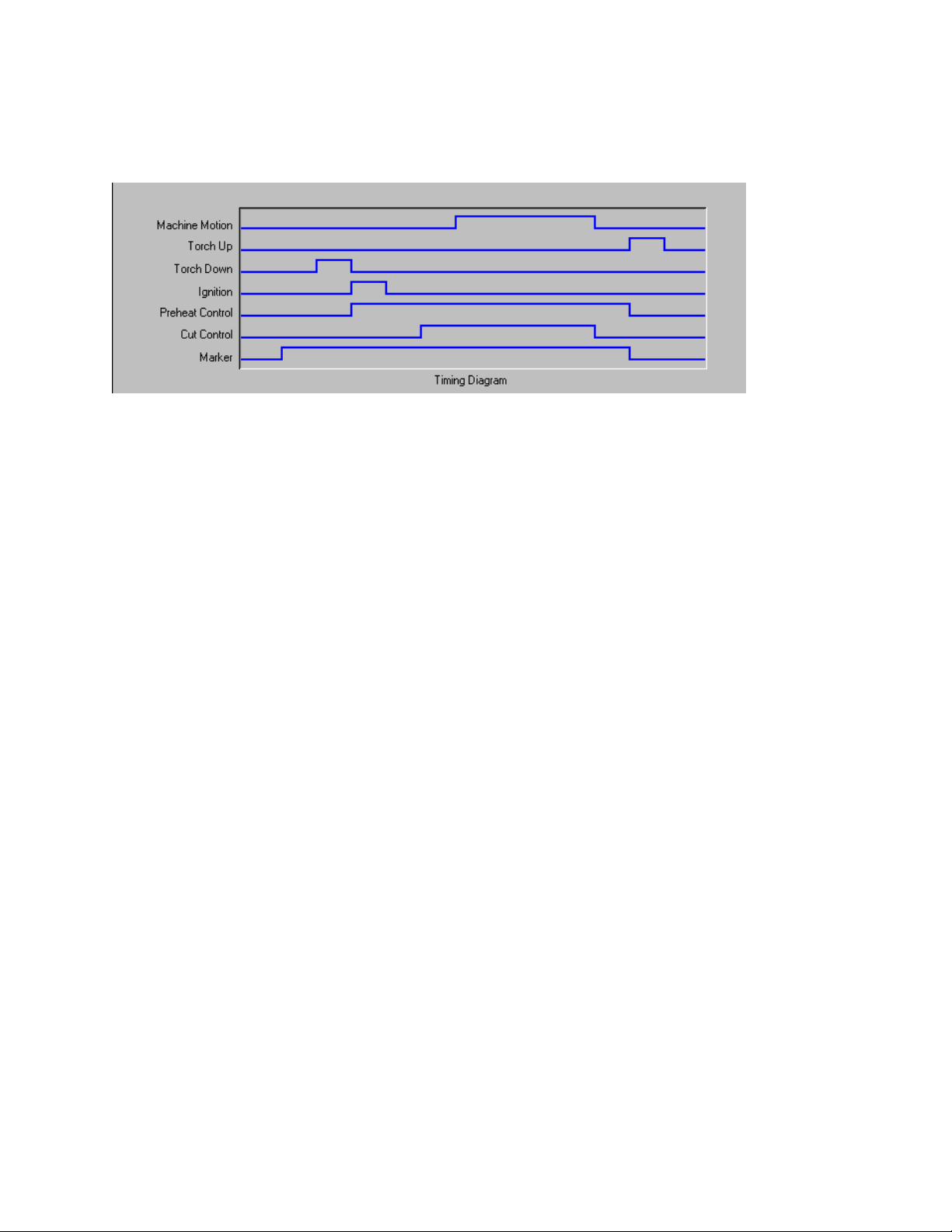
38 Operator’s Manual
I/O Configuration Type “M”, “P” and “V” (Timing Diagram)
Press the Space key to view the timing diagram from Setups.
Ignition Time
(Ignition Output) Specifies the length of time that the ignition output is held on at each ignition point.
Marker On Time
(Time Delay) This parameter allows the operator to insert a time delay, which allows the marker to
prepare for operation prior to the start of Marker motion.
Marker Off Time
(Time Delay) This parameter allows the operator to insert a time delay, which allows the marker to
prepare for operation prior to the end of Marker motion.
Marker Up Time
(Torch Up Output) Specifies the length of time to raise the marker at the beginning and end of each
mark.
Marker Partial Up Time
(Torch Up Output) Specifies the length of time for partial raise of the marker at the beginning and end
of each mark. Note: The Partial Raise parameter must be enabled.
Marker Down Time
(Torch Down Output) Specifies the length of time to lower the marker at the beginning of each
marking cycle.
Set Arc Current
The Set Arc Current feature allows the user to set the arc current at the Plasma Marking supply. This
feature uses the “Set Current BCD” output from the control to activate the BCD inputs at the Plasma
Marking supply. EIA RS-274D part program code G59 Vvalue Fvalue for setting current is supported.
Corner Current Percent
The Corner Current Percent feature allows the operator to select a reduced current setting to be
executed when cutting corners to improve marking quality. This value is a percentage of the Set
Current (above) and is active when the Torch Height Disable Output is on.
Ignition
(Ignition Output Enable) The Ignition Off/On selection allows the operator to use the Ignition Output
when marking if set to On.
Page 53

Section 3: Setups 39
Cut Control Used for Marking
This parameter is used to determine if the Cut Control output is to be used for activating the Marking
tool. If set to no, the Marking Output would be used.
Marker Down/Up With Each Marker On/Off
The Marker Down/Up With Each Marker On/Off will command the send the appropriate Up/Down
Output commands at each Mark On/ Off.
Arc On Feedback
Specifies whether an arc-on signal from a plasma marking system to the control is used. With Arc On
Feedback ON, the control waits for Cut/Mark Sense input to activate before initiating machine motion.
Partial Raise
Enabling the Partial Raise feature will execute a tool raise at the end of the Mark within a nest for the
time specified in the Partial Up Time parameter. Full raise will be executed at the end of the final
Mark segment.
Down On During Mark
Turning on the Down On During Mark feature forces the torch down output to remain on throughout
the Marking process. This is advantageous for pneumatic style torch lifters that require a constant
output.
Down On Between Marks
Turning on the Down On Between Marks feature forces the Torch Down Output to remain on while
traversing between marking segments.
Note: Please refer to the Program Codes section of this guide for information on the Marker Font
Generator feature.
Page 54
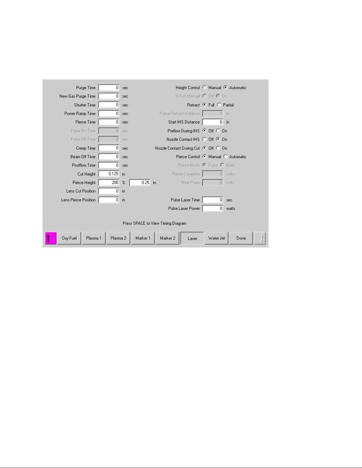
40 Operator’s Manual
Laser
I/O Configuration Type “V” only
Refer to Appendix A: Mariner™ & Voyager II information.
Page 55
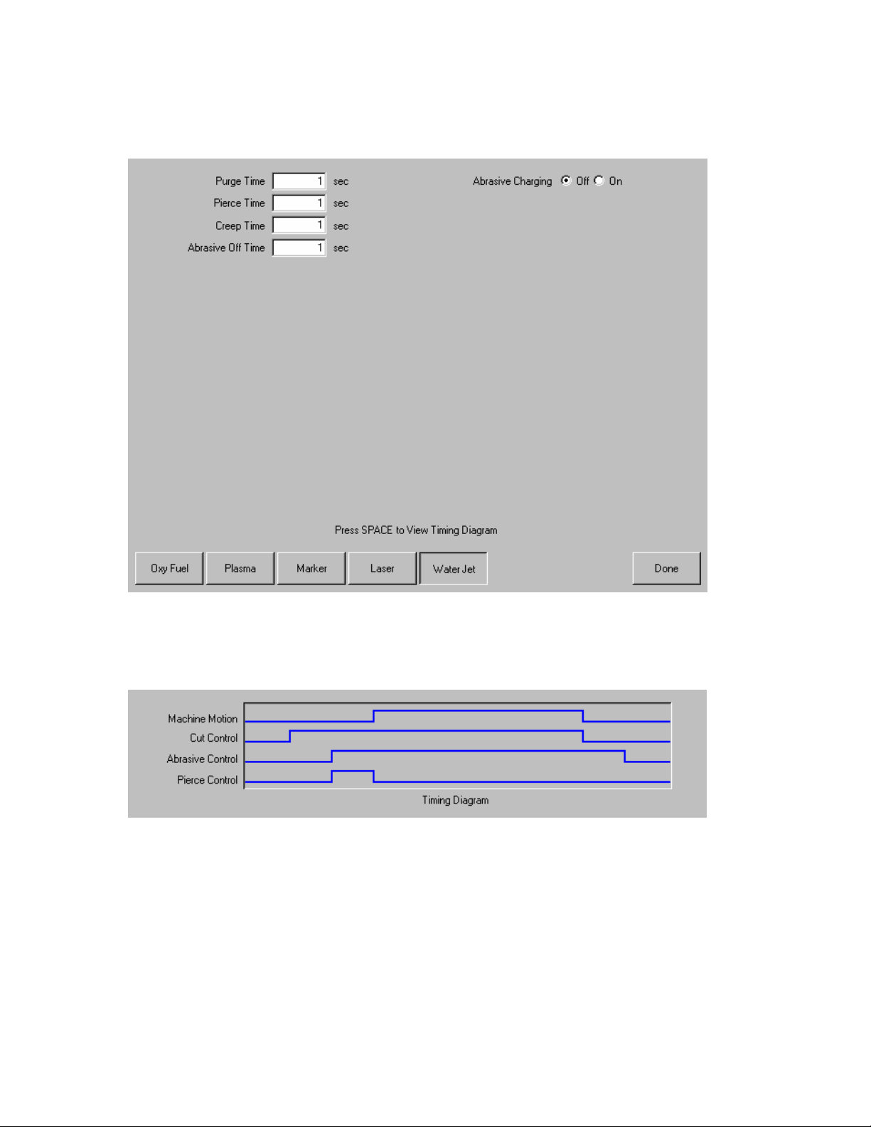
Section 3: Setups 41
Water Jet
I/O Configuration Type “M”, “P” and “V” (Timing Diagram)
Press the Space key to view the timing diagram from Setups.
Purge Time
Specifies the time delay from torch ignition until motion is enabled.
Pierce Time
Specifies the time delay from when cutting tool completes lowering until motion is initiated at Creep
Speed. Used to allow the cutting tool to completely pierce the material before moving.
Page 56

42 Operator’s Manual
Creep Time
Specifies the amount of time after piercing the part that the torch travels at Creep Speed. Creep
Speed is determined by a setup parameter at the Speeds setup screen and is a percentage of the
programmed cut speed. After the Creep Time is completed, the control accelerates to full cut speed.
Abrasive Off Time
The Abrasive Off delay parameter species the amount of time the abrasive will remain on at the end
of a cut.
Abrasive Charging
When selected, the Abrasive Charging feature will charge or fill the abrasive into the cutting system
for use while cutting.
Page 57
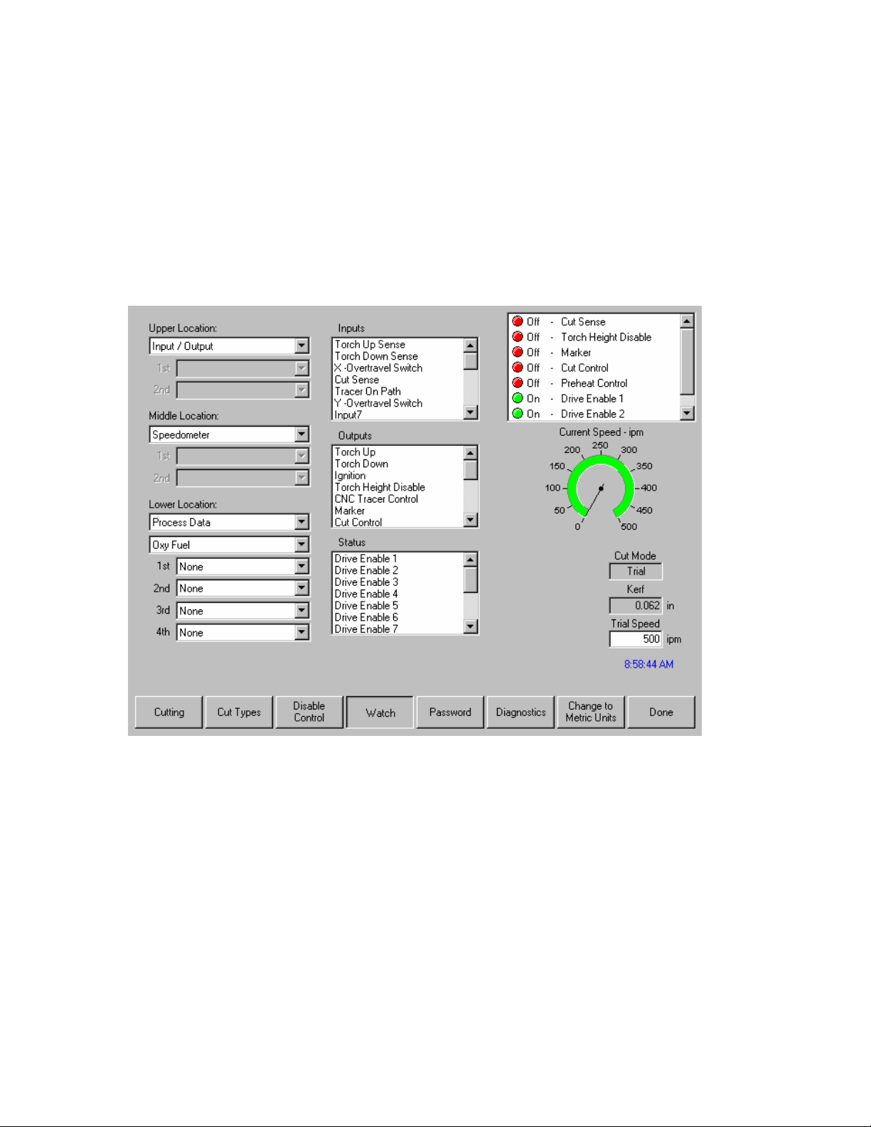
Section 3: Setups 43
Watch
The control comes with a unique function for watching critical process related parameters during
cutting. The Watch window allows the operator to customize a certain portion of the screen to display
functions that are critical for your particular cutting operation. Whether it is Current Speed, Position,
I/O status, or torch consumable life, you now have the flexibility to display the information that you
want to see.
As these parameters are turned ON or OFF, the Watch window will be updated with the new
graphical widget. Widget is a GUI programmer’s term for defining icons which graphically display
information.
Several options are available to personalize the Watch window and not all options can be viewed at
one time. The options are grouped into two sizes of widgets or icons. Large widgets may be placed
into the upper position at the top of the Watch window or in the middle of the Watch window. Small
widgets are positioned in the lower left corner of the Watch Window next to the cut information and
clock. The cut information and clock at the lower right may not be edited.
Selections in the Watch window will change slightly based on the control I/O configuration and
machine option selections that have been enabled.
The Watch positions will allow for the following selections.
None
Selecting None will leave the selected position blank.
Page 58

44 Operator’s Manual
Input/Output
Allows current state of selected Input, Outputs or Status information to be displayed during cutting.
This can be especially useful in debugging gas control sequencing problems. To add or delete a
desired Input, Output or Status point to the Input/Output list box, highlight the desired item and +
(add) or – (delete) keys on the alpha-numeric keypad.
Position
Allows the position for the selected axis to be displayed. Only two axes may be displayed at the
Upper or Middle locations. The Lower location will allow up to four axes to be displayed.
Following Error
Allows the Following Error to be displayed. Following Error is the distance between the position the
control has calculated and the actual position of the torch. A large Following Error may indicate that
the cut speed selected may be beyond the capability of the cutting system. Only two axes may be
displayed at the Upper or Middle locations. The Lower location will allow up to four axes to be
displayed.
Temperature
Selecting to add the Temperature Widgit to the Watch window will display the current temperature
inside the control in Fahrenheit or Celsius (selected at the Special Setups screen). Note: Specific
control hardware required.
Speedometer
Allows cut speed, maximum machine speed and current machine speed to be graphically displayed
while cutting.
Oxy Fuel Torch Tip
Allows the selected oxy fuel torch tip ( 1- 12 ) consumable life to be graphically displayed while
cutting. This is especially useful in helping to determine when the torch tip should be replaced and
keeping track of torch tip data for statistical process control (SPC).
Plasma Torch Tip
Allows the selected plasma torch tip ( 1- 8 ) consumable life to be graphically displayed while cutting.
This is especially useful in helping to determine when the torch tip should be replaced and keeping
track of torch tip data for statistical process control (SPC).
Plasma Electrode
Allows the selected plasma electrode ( 1- 8 ) consumable life to be graphically displayed while
cutting. This is especially useful in helping to determine when the electrode should be replaced and
keeping track of electrode data for statistical process control (SPC).
Process Data
The Process Data option allows the user to view up to four selected items for a selected cut or
marking process. Process timers and status items for Oxy Fuel, Plasma, Marker, Waterjet and Laser
may be selected. Note: The process data will only be displayed during the current cut process.
Example: Plasma 1 process parameters will only be displayed in the Watch window at the main cut
screen while cutting in Plasma 1 Mode.
Laser Nozzle
Laser Nozzle consumable life to be graphically displayed while cutting. This is especially useful in
helping to determine when the nozzle should be replaced and keeping track of nozzle data for
statistical process control (SPC).
HPR Power Supply
Allows the user to view status for inputs, outputs and gas pressures for the HPR130™ autogas
console. Up to four power supplies may be monitored. This is generally used for diagnostics only.
Page 59

Section 3: Setups 45
Multiple Watch Windows
Up to ten different Watch windows may be configured on the control for quick selection and viewing of
the Watch icons.
To configure different Watch windows for viewing, first access the Watch setup screen. Press and
hold the Shift key ( Purple or Blue shift key ) followed by a number ( 0 – 9 ). As you press the Shift
key the current Watch window number will be displayed in the lower right corner of the screen.
Configure the Watch Window as desired.
To select a different Watch window, press and hold the Shift key followed by a number ( 0 – 9 ).
Configure the next Watch window as desired. Continue this process until all desired Watch Windows
have been configured.
To view the various Watch windows during operation, simply press and hold the shift key and the
corresponding number and the desired Watch Window will then be displayed.
Example:
Page 60

46 Operator’s Manual
Page 61

Section 4: Shape Manager 47
Section 4: Shape Manager
Shape Library
The control contains a built-in Shape Library with more than 53 commonly used shapes. These
shapes are parametric. Parametric shapes are shapes that are not fixed in size or geometry.
The Shape Library consists of more than 53 shapes as shown below. The screen is defined in colors,
from the easiest (green) to the hardest (black).
Selecting a Simple Shape
After pressing Shape Library from the Main Menu, the control display shows the Shape Library as
shown above. At this time, simply use the arrow keys to navigate to the desired shape you wish to
cut and press ENTER. If the selection is incorrect, press CANCEL and re-select the shape.
At this point, the shape is displayed with the default parameters, or the parameters from the last edit
session of this shape. Detailed information on the available shapes can be found in the following
section.
Page 62

48 Operator’s Manual
Text Editor
This screen is for manually inputting or editing of a part program in either ESSI or EIA format. The
current part that is in memory will be displayed upon entering this screen. Done will save any
changes to the current part in memory. If you want to save the changes to the hard drive, go to the
Save to Disk screen. If you do not want to save any changes that were made, press Cancel on the
keyboard.
Show Original Text
Pressing the Show Original Text button allows the user to view and edit the part program in the
original format in which it was written.
Delete Part
The Delete Part button will delete the current part from the Text Editor so that a new part can be
constructed.
Page 63

Section 4: Shape Manager 49
Shape Wizard
ShapeWizard, a proprietary graphical part editor, provides a user-friendly, graphical method of
editing part programs.
ShapeWizard
any changes that are made, when they happen. EIA RS-274D codes can be inserted directly as
ASCII text into a part program or, alternatively, segments can be created by specifying phrases in the
user's native language as a step-by-step process. EIA RS-274D codes need not be known.
ShapeWizard
allows a user to graphically view not only the segment that is being edited, but also
is accessed from the Shape Library menu.
Manual Line Edit
Pressing Manual Line Edit allows editing the highlighted line in the Text Editor window. The ASCII
text entered must be valid EIA RS-274D codes or an error message will result. Below is a Text Editor
line as it appears immediately after the Manual Line Edit is pressed:
Page 64

50 Operator’s Manual
Simply typing right over the line can erase the highlighted text or the line can be edited using the left
and right arrow keys.
Replace Segment
Replaces the segment highlighted in gray in the Text Editor window with the segment selected from
the Segment Type window as pictured below:
Insert Before Segment
Pressing this softkey causes the segment selected from the Segment Type window to be inserted
before the segment highlighted in gray in the Text Editor window.
Insert After Segment
Pressing this softkey causes the segment selected from the Segment Type window to be inserted
after the segment highlighted in gray in the Text Editor window.
Remove Segment
The segment highlighted in gray or blue in the Text Editor window is removed from the part program
when the Remove Segment softkey is pressed.
After the Manual Line Edit softkey has been pressed, the left and right arrow keys on the front panel
can be used to move left and right within the line being edited in the Text Editor window. They also
are used when entering segment parameters for new Segment Types such as:
Page 65
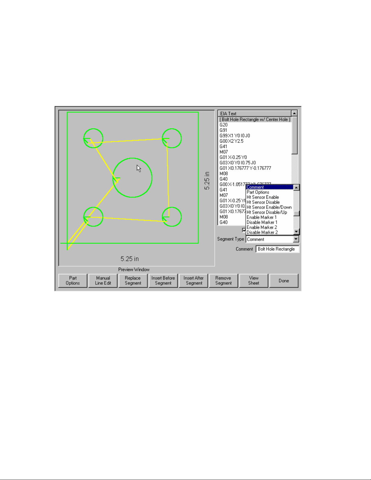
Section 4: Shape Manager 51
While a text line is highlighted in blue, the Up and Down arrow keys are used to scroll vertically
through the part program. With each press of one of these keys, a new segment is highlighted. In
addition, the graphic representation of the part program in the Preview window is updated so that the
corresponding segment is highlighted in red or blue, depending on whether it is a cut segment or a
traverse.
The Up and Down arrow keys are also used when the Segment Type pop-up window is highlighted to
scroll vertically through the list of segments. The Segment Type pop-up window is pictured below:
The PAGE UP and PAGE DOWN keys can also be used wherever the Up and Down arrow keys are
used. The only difference is that instead of moving up or down one line, PAGE UP and PAGE DOWN
moves 20 lines at a time.
Pressing PREV and NEXT moves the edit focus to the next window. For example, when a user enters
ShapeWizard, the first line in the Text Editor window is highlighted. If a new segment selection is
desired, the user must press either PREV or NEXT until a selection in the Segment Type window is
highlighted. Pressing NEXT again will cause the control to skip ahead and once again highlight a line
in the Text Editor window. As a rule, NEXT always moves the selection flow ahead and PREV moves
it backwards.
As soon as it becomes highlighted, the Segment Type window expands or pops-up. This allows the
user to view a larger selection of segment types. See the picture above.
After a selection is made in the Segment Type window, pressing ENTER will cause the control to
display up to three parameters associated with the segment selected. Not all segments have any
parameters associated with them. For example, End Program does not need any additional
parameters.
Page 66
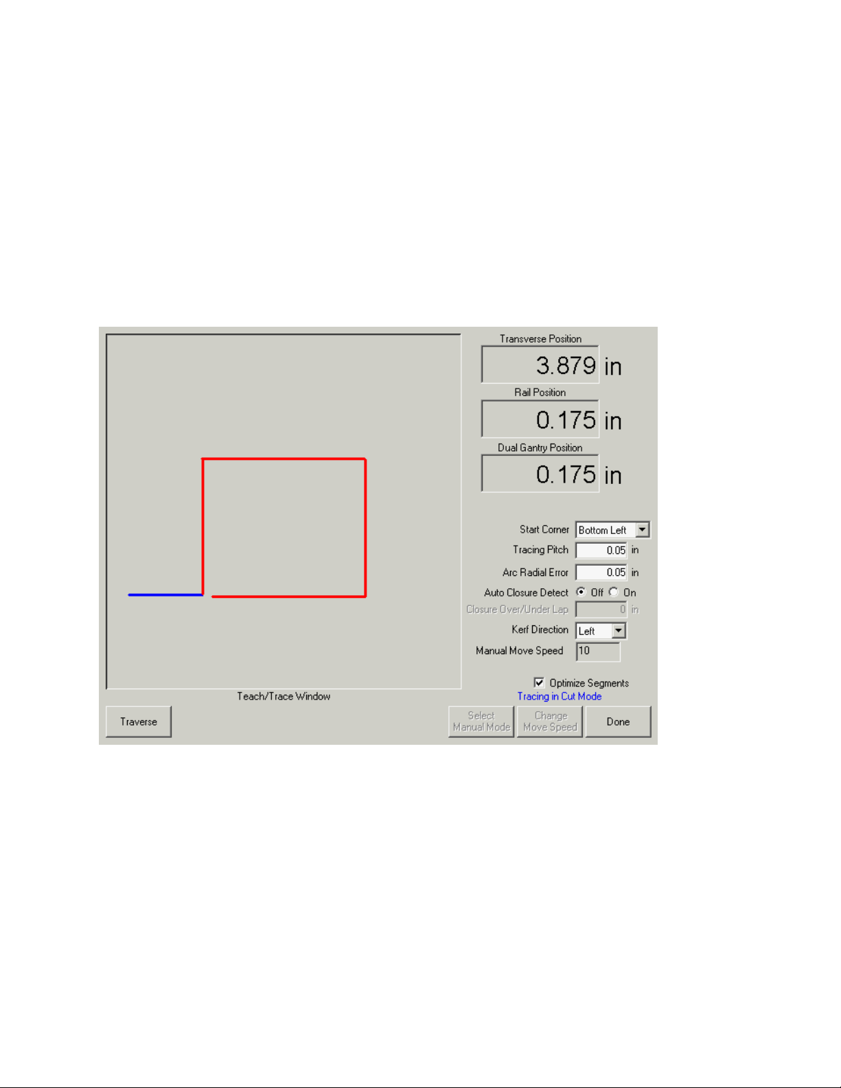
52 Operator’s Manual
Teach Trace
The Teach Trace function of the control allows parts to be taught rather than programmed. The
position information from the taught part will remain as a part program that can be saved to disk for
future use.
The Teach Trace algorithms present in the control can recognize both arcs and lines. This will
reduce the overall memory required to store these parts and will improve the smoothness of the cut.
The taught part in memory is in EIA format and can be cut, saved or manipulated using any of the
part options.
The Teach Trace function must be used in conjunction with an optional stand-alone optical tracing
system.
Start Corner
The Start Corner setup parameter allows the user to select where the taught part will begin for proper
viewing on the screen.
Tracing Pitch
This determines how precisely to learn a part. The Tracing Pitch can be adjusted to trade off
resolution versus size of the taught part. This value does not affect the actual position resolution of
the part.
A good starting point for most tracing systems is 0.01”.
Page 67

Section 4: Shape Manager 53
Arc Radial Error
Specifies the arc error tolerance to be used when checking the current segment for dimensional
accuracy. All ESSI or EIA programs are comprised of lines, arcs and circles. Arc Radial Error is
used to ensure that the starting and ending radial vectors are within tolerance to describe a valid
geometry.
Auto Closure Detect
This parameter is used to allow the control to detect that it has returned to the starting point. With this
feature ON, the control stops the motion of the tracer when the part is complete allowing a lead-out to
be programmed.
Closure Over/Under Lap
By specifying a positive value for this parameter, the control does not stop the tracer until it has gone
past the start point by the amount of this parameter. By specifying a negative value, the tracer stops
as soon as the tracing head position is within this parameter’s distance of the starting point. This is
only available if the Auto Closure Detect is ON.
Kerf Direction
Selects the desired kerf for cut segments.
Traverse/Pierce
Switches between the traverse and cut segments of the part as it is taught.
Tracing a part
To trace a part while at the Teach Trace screen, select Auto mode, then select traverse or pierce.
You may switch between traverse and pierce during the tracing procedure. Position the optical
sensor near the part drawing and press Start. Use the sensor positioning controls to direct the sensor
towards the part. Once the sensor has located the part, the tracing system will follow the part outline
until completion. When completed, press Done. The part file can now be cut, saved or edited.
Please refer to the instructions provided with your Optical tracing system for further details.
Page 68
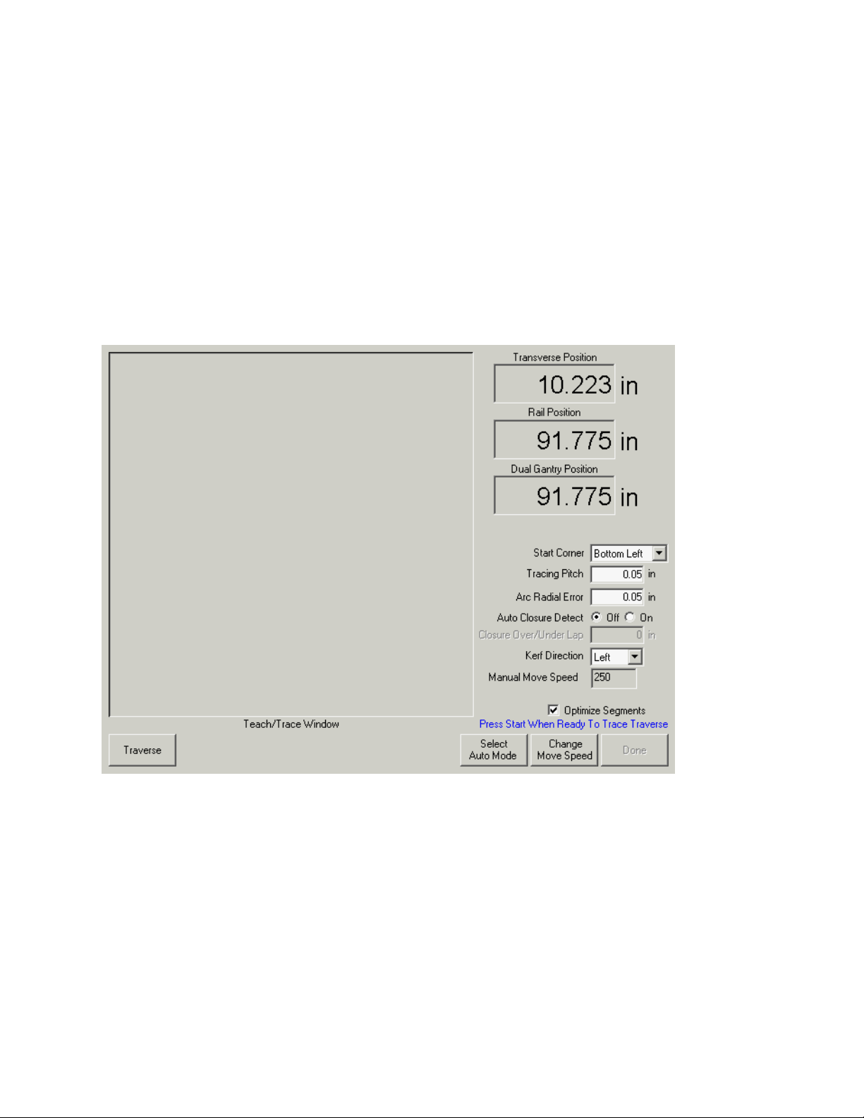
54 Operator’s Manual
Plate Remnant Trace
The Teach /Trace feature also supports the ability to trace in the outline of a plate remnant for use by
a part programmer to create new nests of parts to be cut on the remnant.
The user manually moves the torch (or a pointer) around the plate to define the outline of the
material which remains. When the path is completed (it doesn’t have to be a closed path), the
operator presses the Done key and the recorded axis motions are written to a standard part program
format with moves recorded as incremental routing moves. The movements will also display on the
control’s screen in the same manner as displayed during manual motion commands.
Once recorded, the part program can be uploaded via the serial link, or written to the floppy disk, so
that the programming department can use it to update their database to reflect the remaining
material.
When first opened the system defaults to the automatic Teach/Trace mode which is used in
conjunction with an optical head for program generation. In order to use the manual function, simply
select the softkey to choose manual mode.
This will place the control in the manual control mode and also enables the Change Move Speed
button to alter the manual move speed. Pressing the Change Move Speed button repeatedly will
cycle through the programmed manual jog rate settings.
Page 69
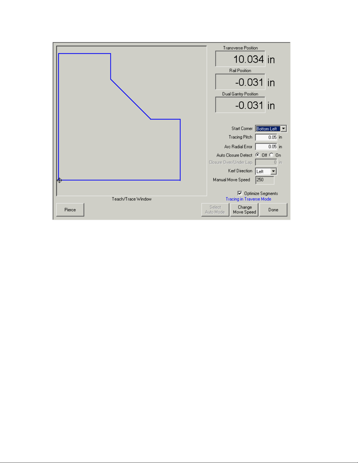
Section 4: Shape Manager 55
This will place the control in the manual control mode and also enables the Change Move Speed
button to alter the manual move speed. Pressing the Change Move Speed button repeatedly will
cycle through the programmed manual jog rate settings.
The operator should position the pointer or torch to the plate location where recording of the path is to
begin. Once at the start point, press the “Start” button to begin recording positions. The manual
motion buttons may now be used to trace out an arbitrary contour which defines the remaining plate
area. When finished, press the Done key to record the motions to the “current” part program.
The program may now be saved to the disk, or uploaded in the normal manner.
Page 70
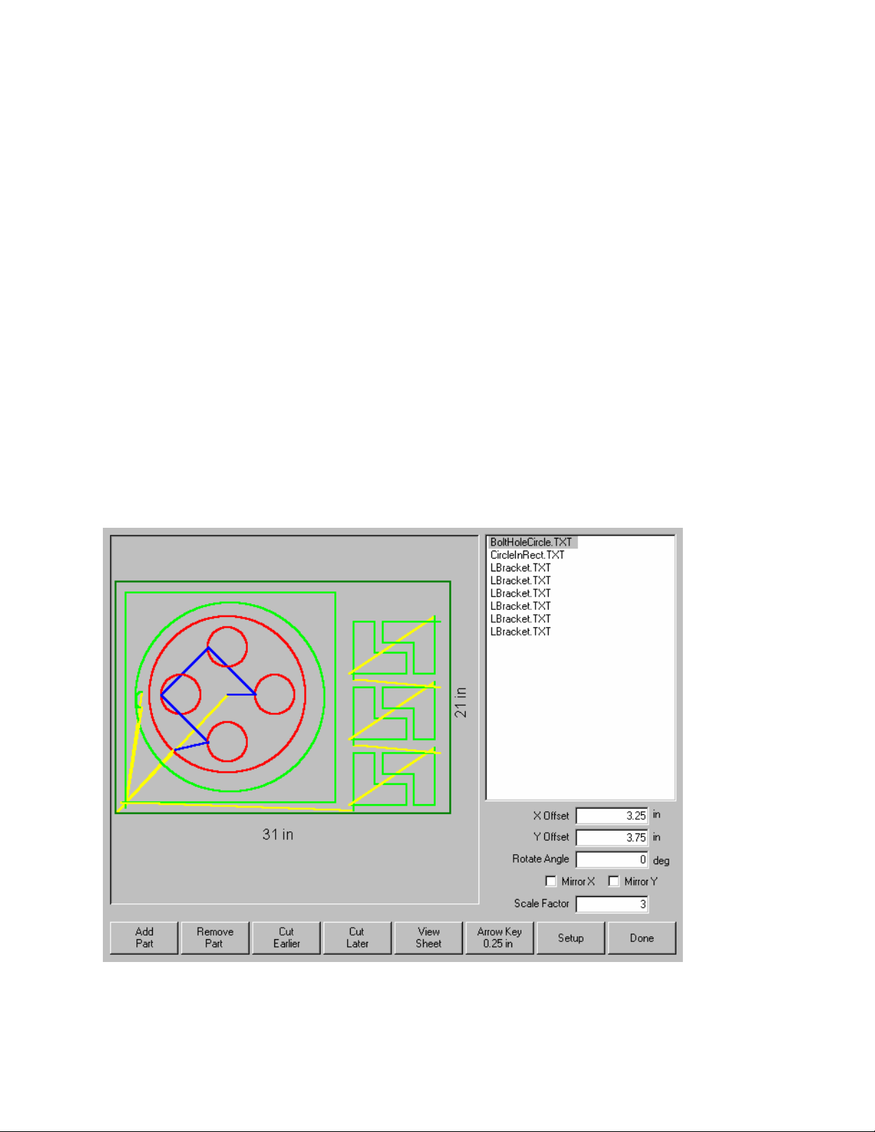
56 Operator’s Manual
Nester™
Nester™ is a proprietary part nesting program, which allows the operator to manually group or nest
selected parts together as one part program to conserve raw materials and maximize machine
utilization. This nesting program is designed to maximize the control features of graphical user
interface, simplified keypad operation and advanced communications software to provide quick,
simple and logical programming.
Additionally, an optional Automatic Nesting feature may be enabled to perform true shape, single
station, automatic nesting. With its advanced Graphical User Interface, ease of use and advanced
profile positioning algorithms, this Automatic Nesting feature can greatly improve the output of your
shape cutting operation by reducing overall process time and increasing plate utilization. Please
contact your control vendor for details on enabling this Automatic Nesting feature.
Manual Nesting
Main Screen Layout
The main viewing area is the largest area of the screen and is located in the upper left corner. The
edge of the plate is displayed in dark green. The plate size displayed is based on plate information
that has been selected at the main setup screen.
The upper right corner of the main screen displays the part program list for the nest in order of cut
sequence. In the lower right, part position and orientation information for the selected part program is
displayed and can be manipulated for use as new parts are added.
Page 71

Section 4: Shape Manager 57
Add Part
Pressing the Add Part softkey accesses the screen, which allows the user to select a part program
from a selected source.
Remove Part
This softkey is used to remove the selected part from the nest parts list.
Cut Earlier
Pressing the Cut Earlier softkey will move the selected part program to an earlier position in the part
cut list. The sequence in which the parts are cut are changed, but not the selected part location in the
nest.
Cut Later
Pressing the Cut Later softkey will move the selected part program to a later position in the part cut
list. The sequence in which the parts are cut are changed, but not the selected part location in the
nest.
View Sheet / View Part
View Sheet allows the viewing of a part as it would appear on the plate. After pressing the View Sheet
softkey, the display window zooms out to show the part in relationship to the entire plate.
After zooming out, the display can be zoomed in again by pressing the + key, which causes horizontal
and vertical scroll bars to be displayed. Pressing the - key will zoom back out.
More information on use of this feature is provided in the Manual cutting section.
Arrow Key ( Distance )
The Arrow Key allows the user to select one of five different preset move distances when the arrow
keys are pressed to locate parts in the nest. These five distances are definable and are selected in
the Nester™ Setup screen.
Setup
Pressing the Setup softkey accesses the Nester™ Setup screen for configuring the variable
parameters when using Nester™.
Done
The Done softkey is used to end the Nesting program, return to the Main Cut Screen and temporarily
save the nested program as the current part. At this point, the part can be cut or saved to disk
through the Shape Manager. Pressing the cancel key will return the user to the Main Cut Screen
without saving the nested program.
Page 72
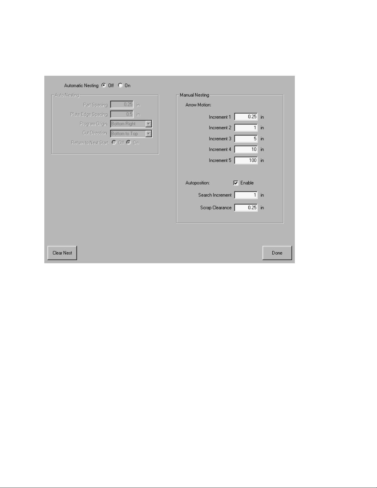
58 Operator’s Manual
Nester™ Setup
The following Setup parameters are used to configure the manual nesting process for use.
Arrow Motion
At this screen, the user can select different move increment dimensions. These dimensions are used
as move distance references when the control arrow keys are pressed to place parts in position on
the plate.
Autoposition
Autoposition is an automated feature of the Nester™ software to search for the next available location
to place a part that is being added to the nested part list. Autoposition compares the overall block
dimensions of the selected part and searches for the next available block on the plate that is large
enough to accommodate the part being loaded. Values can be input for the Search Increment and
Scrap Clearance parameters that are used when searching for the next available part location.
Autoposition will not allow parts to be placed on top of other parts or inside other parts. This feature
is enabled or disabled by using the space key at the enable box.
Clear Nest
Clear Nest will delete all the parts located in the nested parts list from temporary memory.
Done
The Done softkey is used to end the nesting setup and return to the Nester™ main screen.
Page 73

Section 4: Shape Manager 59
Using Nester™
To begin, first select the plate size requirements for the nest at the Main Setup screen. This
information is used to display the plate size and plate orientation at the main view screen to place
parts on the plate. The plate information is retained with the nested part program when saved.
Press the Nester™ softkey from the Shape Manager screen then enter the Nester™ Setup Screen to
configure the nesting software for use. Press Done to return to the Nester™ Main Screen to begin
placing parts in the nest.
Adding Parts
At the Nester™ Main Screen, press the Add Part softkey to add a new part to the nesting part list.
The first screen viewed will allow the user to select a part from the Simple Shape Library, from a disk
or from the host computer via link communications.
Once a part has been selected from either location, the user will be prompted to select the number of
pieces desired.
Page 74

60 Operator’s Manual
As new parts are added, they will be displayed on the selected plate in preparation for final
placement.
At this screen, the part can be oriented, scaled and moved to final position. This is done by moving to
the Nester™ Part List by using the Prev/Next keys and then using the Up/Down arrow keys to select.
When the desired part file is highlighted, use the Prev/Next keys to move to the desired field to
manually offset, rotate, mirror and scale the part.
To position the selected part, use the Prev/Next keys to highlight the view screen. The view screen
will be outlined by a bold blue border indicating that the arrow keys are active. Pressing the arrow
keys will allow movement of the part to the desired location on the plate. Each time the arrow keys
are pressed, the selected part will move in the direction of the arrow by the increment set by the
Arrow Key distance softkey. By use of the arrow distance key, arrow keys and zooming in the view
field, exact placement of the desired part may be obtained.
Additional parts may be added to the nest in the same fashion as described above. To customize
your nest, you may decide to delete parts or add parts to the list and change the order in which they
are cut by use of the softkeys displayed. When finished, press Done to return to the Main Cut screen
and begin cutting the nest. The part nest is currently saved as a temporary file until another part is
loaded.
Saving a Nest
From the Main Cut screen, press the Files softkey to Save to Disk. From here the part can be saved
to a hard disk folder on the control or a diskette. The nested parts file may be saved as a nest or a
part. Saving as a nest will create a larger file, which will allow future modification of the nest through
Nester™. Nested parts saved as a part file cannot be modified.
Page 75

Section 4: Shape Manager 61
HyperNest – CNC® Automatic Nesting Software
Optional HyperNest® - CNC feature - This true shape, single station, automatic nesting package
allows quick and simple nesting of profiles on to selected material sizes. With its advanced Graphical
User Interface, ease of use and advanced profile positioning algorithms, HyperNest
greatly improve the output of your shape cutting operation by reducing overall process time and
increasing plate utilization.
Main Screen Layout
The main viewing area is the largest area of the screen and is located in the upper left corner and is
used to preview manual nests. During an automatic nest, this area will remain blank. The plate size
used during Automatic nesting is based on plate information that has been selected at the main setup
screen.
The upper right corner of the main screen displays the list part programs and quantities of parts to be
automatically nested. In the lower right, locations to save the nested part program to a folder location
and to assign a file name.
®
- CNC can
Note: This software feature is protected both by a software enable and a hardware key (dongle)
installed on the control.
Page 76

62 Operator’s Manual
Automatic Nesting Setup
Pressing the Setup softkey accesses the following setup parameters and are used to configure the
automatic nesting process for use. Note: If this feature is not available (greyed out), the feature has
not been enabled on your controller. Please contact your control vendor for details on how to enable
the Automatic Nesting feature.
Automatic Nesting
Switching the Automatic Nesting Parameter to ON enables the feature for use.
Part Spacing
The Part Spacing feature sets the spacing between parts during the Automatic Nesting process.
Plate Edge Spacing
This parameter allows the user to set spacing around the edge of the plate to be used during the
Automatic Nesting process.
Program Origin
The Program Origin ( nest start location ) may be set to lower left, upper left, bottom left or bottom
right.
Cut Direction
Cut Direction allows to user to select the direction the parts will be placed in during the Automatic
Nesting process. Options are: Left or Right, Right to Left, Top to Bottom and Bottom to Top.
Return to Nest Start
When enabled, the Return to Nest Start feature will insert a traverse segment back to the start point
at the end of the nest.
Page 77

Section 4: Shape Manager 63
Using HyperNest – CNC®
To begin, first select the plate size requirements for the nest at the Main Setup screen. Press the
Nester™ softkey from the Shape Manager Screen then enter the Setup Screen to enable the
Automatic Nesting software feature and configure the setup parameters for use. Press Done to
return to the Main Screen and begin placing parts in the nest.
Adding Parts
At the Main Screen, press the Add Part softkey to add a new part to the nesting part list. The Add
Part screen will allow the user to select a part from the Simple Shape Library, from a disk or from the
host computer via link communications.
Once a part has been selected from the desired location, the user will be prompted to select the
number of pieces desired.
Page 78

64 Operator’s Manual
As new parts are added, the part file name and quantity will be displayed in the parts list window in
the upper right corner of the screen in preparation for final placement during the Automatic Nesting
process.
Select the desired file location and assign a file then press the Nest Parts softkey to begin the
automatic nesting process. A progress window will be displayed during the nesting process.
Page 79

Section 4: Shape Manager 65
Note: The nest process progresses quickly and not all shapes may be visible on screen or other
drawing anomalies may be noted during the nesting process.
In the event that more parts are selected than can fit on one plate, multiple plates or sheets (nested
program) files will be generated and saved in the selected folder with the selected file name, but a
numeric suffix will be added. Example: saving the part file as Nest may generate multiple part files
named NEST1.txt, NEST2.txt, NEST3.txt, etc.
Remove Part
A part may be removed from the part files list by highlighting the selected part in the files list and
pressing the Remove Part softkey prior to executing the nesting.
Note: The software feature on the control is protected by a hardware key or dongle. If the
hardeware key has been removed from the control, the following message will appear when the Nest
Parts softkey has been pressed.
Page 80
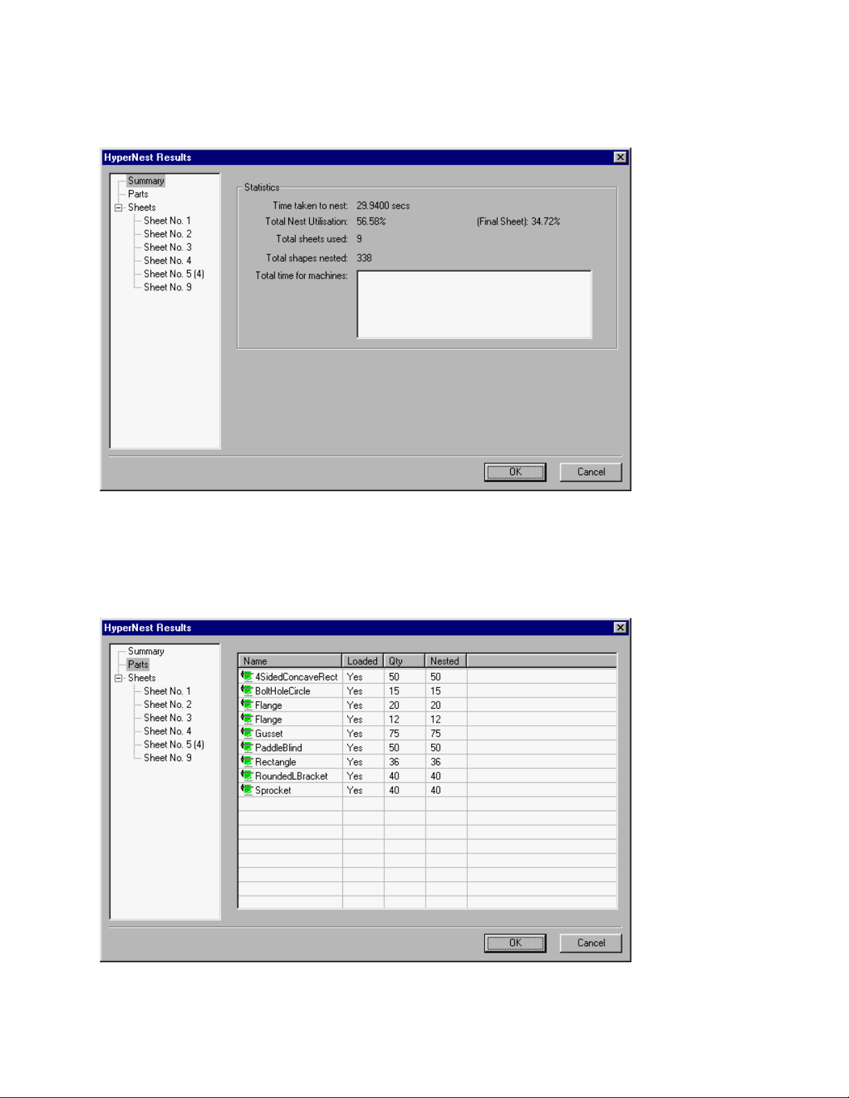
66 Operator’s Manual
Nest Summary
Upon completion of the nest, the software will provide a summary of the Automatic Nesting process.
Statistical analysis of the process is provided for a number of sheets, time to execute nest, total nest
utilization and total number of shapes nested.
Note: Sheets that are generated with the exact same part configuration will be listed as “Sheet No. #
(total #). For the example above, the sheet number 5 thru 8 sheets are all the same and are listed as
“Sheet No.5 (4)”
Pressing the down arrow key will allow you to view an analysis of the parts used.
Page 81

Section 4: Shape Manager 67
Pressing the down arrow key again will allow you to view the individual sheets produced and a listing
of the net utilization for the specific sheet.
Press Enter to accept the nest and have the first sheet become the current part. Press the Cancel
key to reject the nest and return to the main nesting screen to add or remove parts from the nest.
Page 82
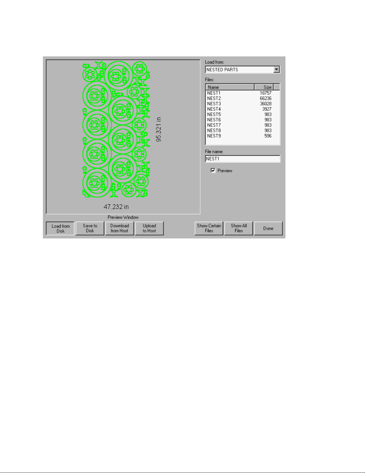
68 Operator’s Manual
Main Screen View of Nest
Note: Parts with open loops or other invalid geometries may not be able to be automatically nested.
It may be possible to manually nest parts which have been rejected by the Automatic Nesting
function.
Page 83
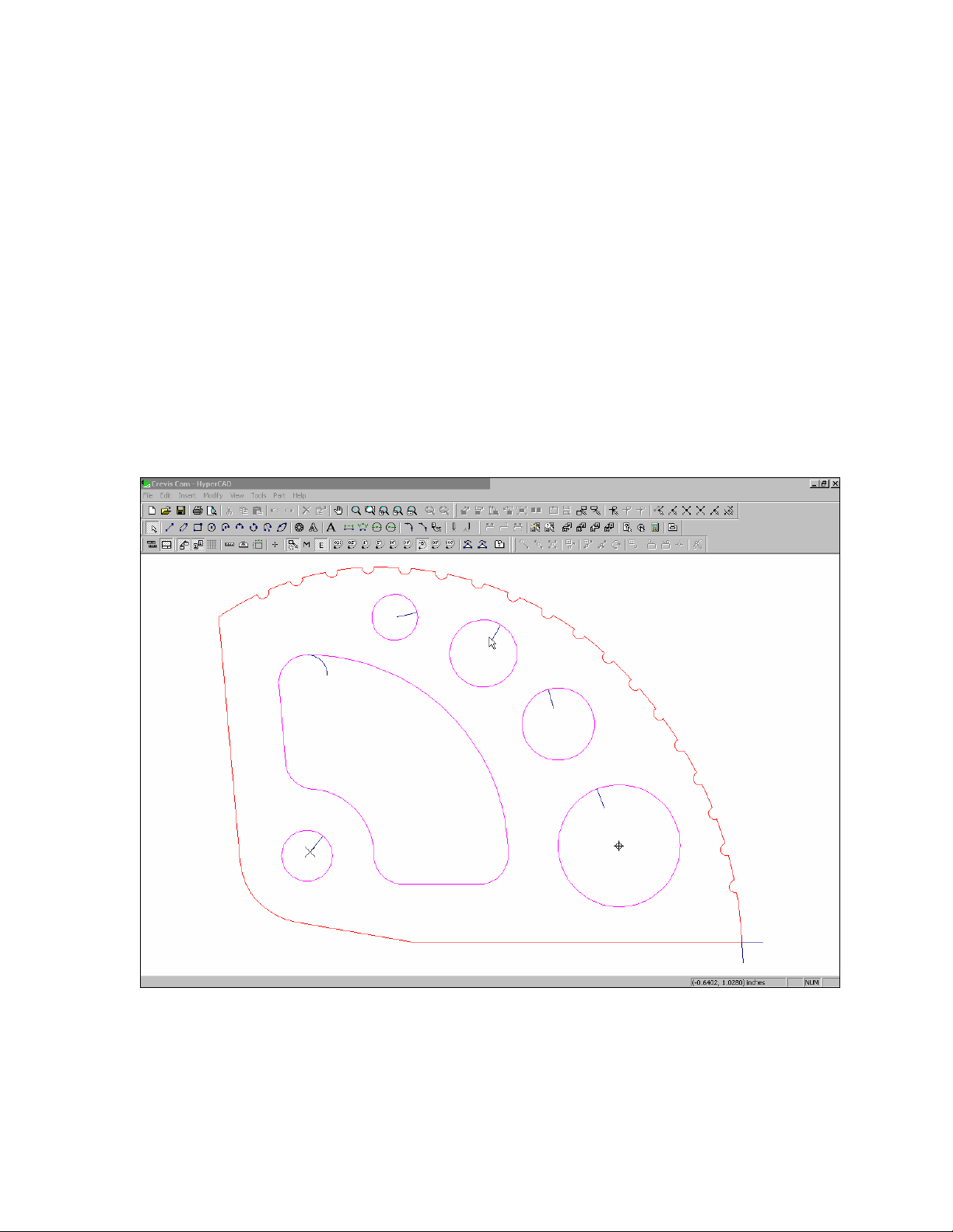
Section 4: Shape Manager 69
HyperCAD®
HyperCAD® is an easy to use 2D drawing application specifically designed for shape cutting. The
software’s powerful CAD utilities let users import DXF and CNC files or draw from scratch. Files can
be converted to graphical parts for editing and saving or go directly to cutting.
This simple CAD/CAM application lets you move easily from drawing to cutting.
HyperCAD
- English or Metric Units
- Part / Sheet viewing capabilities
- Scaling, mirroring or rotating of parts
- Repeating and copying of shapes
- Moving / modifying of lead-ins and lead-outs
- Add-on of chamfers, fillets and notches
- On-screen, full-part cutting simulation
- Built in Help functions
®
Features
This feature is offered as a limited use trial version. Please contact your control vendor for
information on enabling unlimited use of this feature. This package may be used on the CNC
equipped with mouse and PC keyboard or offline on a PC.
Page 84

70 Operator’s Manual
HyperNEST®
HyperNEST® is a full featured, automatic true shape application designed to allow quick and simple
nesting of profiles onto standard material sizes. With its advanced Graphical User Interface,
HyperNEST
HyperNEST
HyperNEST
- Multi-torch nesting with a variable number of torches
- Bridging and chain cutting for common line cutting
- Extending consumable life
- “Move, drag and drop” manual interactive nesting
- Viewing and modifying of multiple sheets at the same time
- Multiple nesting scenarios for optimizing plate use and process cutting time
- Use of Wild Card parts to optimize plate utilization
- Automatic off-cut generation
- Built in Help functions
®
greatly improves the output of any shape cutting operation.
®
Features
®
also lets mechanized end users achieve
This feature is offered as a limited use trial version. Please contact your control vendor for
information on enabling unlimited use of this feature. This package may be used on the CNC
equipped with mouse and PC keyboard or offline on a PC.
Page 85
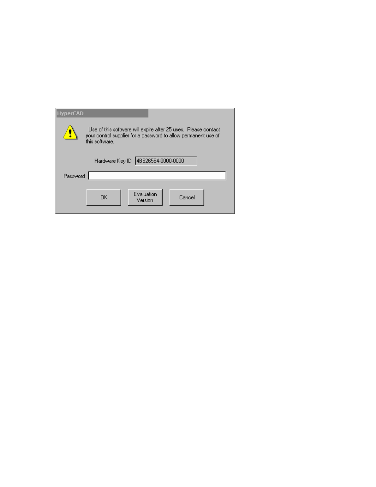
Section 4: Shape Manager 71
Evaluation Timer
Trail version software will prompt the user with a notification of the number of “uses” left at each
launch. To enable unlimited use, a password would be provided by the control vendor.
To launch the trial software, select the Evaluation Version.
Example:
Page 86

72 Operator’s Manual
Page 87
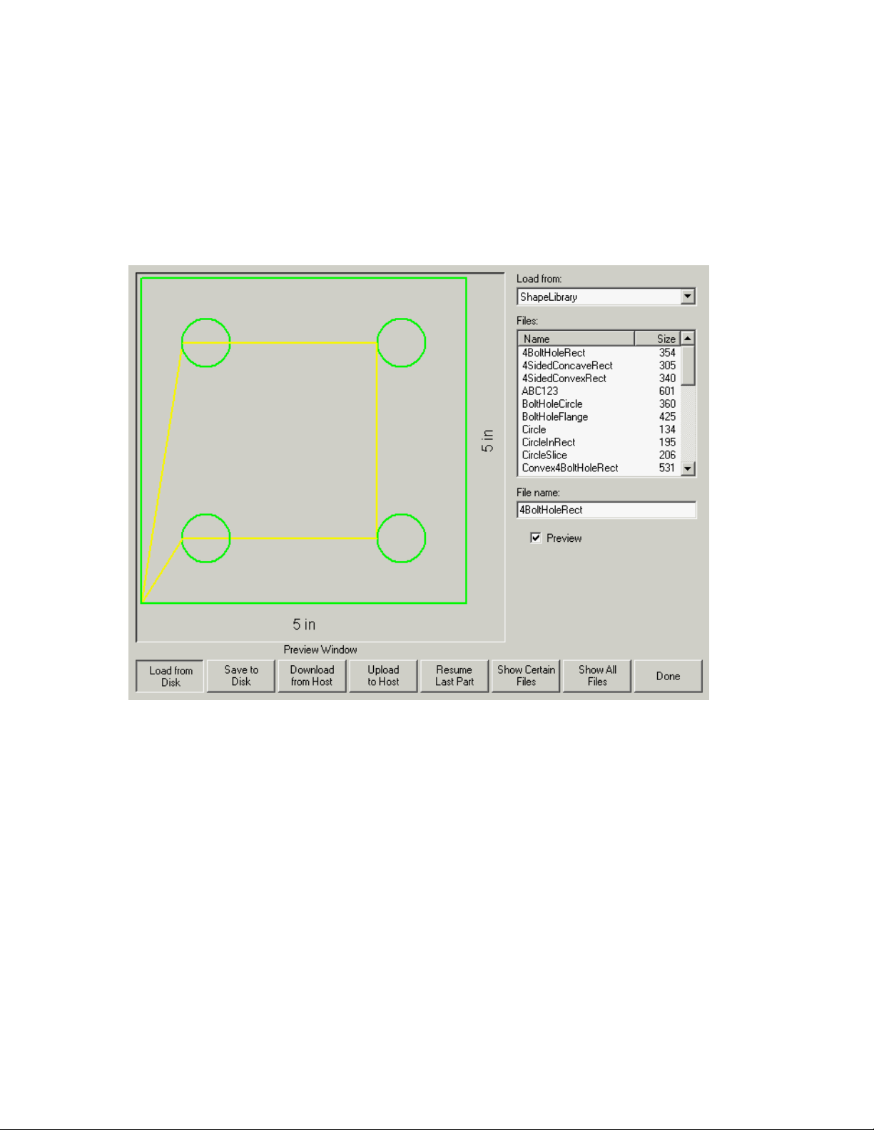
Section 5: Files 73
Section 5: Files
Load from Disk
The following screen is used to load a part from a diskette or the hard drive. Once all the parameters
below are set, press ENTER on the keyboard to load the part.
Load from
The Load from list selects whether you load from the diskette or from a directory on the hard disk. To
select a different directory, use the ↑ and ↓ keys on the keyboard. To add a new directory, use the +
key on the keyboard. To remove a directory, use the - key on the keyboard.
Files
The Files listbox is a list of all the files that are in the Load from directory that can be loaded from the
disk. To scroll through different files, use the ↑, ↓, PAGE UP and PAGE DOWN keys on the
keyboard. To remove a file, use the - key on the keyboard. To select multiple files to load, highlight
the first file selection, then use the ↑ and ↓ keys while pressing the shift key to highlight the remaining
files. Note: Multiple file selection is only available if loading from the diskette to the hard drive.
Page 88

74 Operator’s Manual
File name/Diskette file name
The File name /Diskette file name is the name of the file to load from disk/diskette.
Preview
When checked, the Preview checkbox allows the file that is selected in the Files listbox to be
previewed. To check or uncheck the box, press the SPACE key on the keyboard when the Preview
box has the focus.
Load to
The Load to list selects whether you load to the current part or to a directory on the hard disk. To
select a different directory, use the ↑ and ↓ keys on the keyboard. To add a new directory, use the +
key on the keyboard. To remove a directory, use the - key on the keyboard. Note: This selection is
only available if loading from the diskette.
Hard drive file name
The Hard drive file name is the name that you are giving the file you are loading on the hard drive.
Note: This selection is only available if loading from the diskette.
Resume Last Part
The Resume Last Part softkey will be visible when the Rush Job Interrupt or Automated Power Loss
Recovery feature is in use. These features allow the user to pause the current part program and
retain the part and current position information. This then allows the user to load and execute
another part program and return to the original part using the Resume Last Part softkey.
Show Certain Files
This softkey allows the operator to search the selected folder for specific part files by using wildcard
type search tools. Both the asterisk (*) and question mark (?) can be used. To input the asterisk,
press the left shift key (purple) and the backspace key. To input the question mark, press the right
shift key (blue) and the backspace key.
Show All Files
This will allow the operator to switch from the selected “certain files” to viewing all files with the
predetermined file extensions.
Page 89
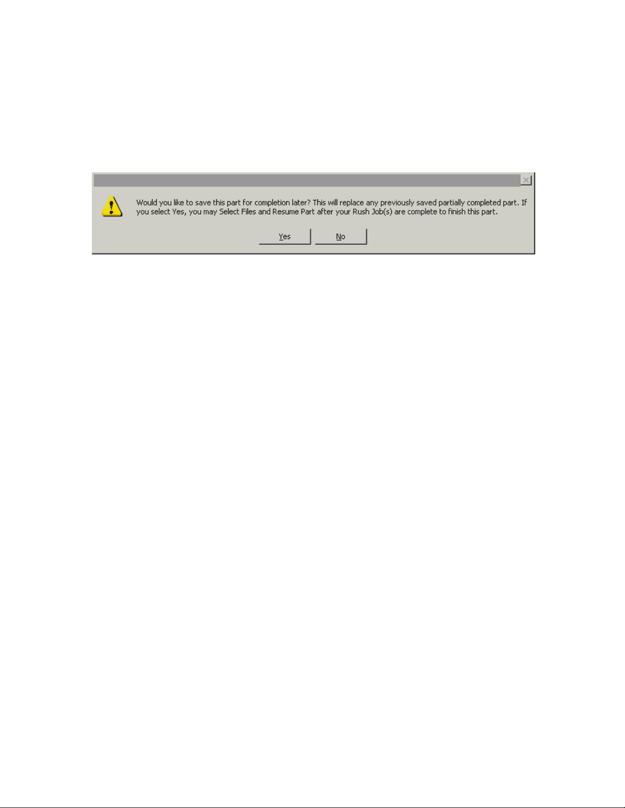
Section 5: Files 75
Resume Last Part Features
Rush Job Interrupt
Rush Job Interrupt allows the user to pause the current part program and retain the part and current
position information. When at the Pause screen, press the Cancel key. A prompt will appear on
screen to ask the user if they wish to save the part information for later use.
If the user selects YES, the Resume Last Part button will be viewable at the Files Screen. The user
can then load and execute another part program and then return to the original part using the
Resume Last Part softkey. The part program and position will be resumed.
Automated Power Loss Recovery
The Automated Power loss recovery uses the Resume Last Part feature similar to the Rush Job
Interrupt. However, the Machine must be “Homed” to ensure proper positioning prior to resuming the
part.
This feature may also be used in the event of an “Overtravel” or similar fault.
Page 90

76 Operator’s Manual
Save to Disk
The following screen is used to save a part to a diskette or the hard drive. Once all the parameters
below are set, press ENTER on the keyboard to save the part.
Save to
The Save to list selects whether you save to the diskette or to a directory on the hard disk. To select
a different directory, use the ↑ and ↓ keys on the keyboard. To add a new directory, use the + key on
the keyboard. To remove a directory, use the - key on the keyboard.
File name/Diskette file name
The File name is the name that you are giving the file you are loading on the disk.
Save Original Text
Selecting the Save Original Text option will save the part to disk in its original programming format.
Note: This selection is not available if saving to the diskette from the hard drive.
Save from
The Save from list selects whether you save from the current part or from a directory on the hard disk.
To select a different directory, use the ↑ and ↓ keys on the keyboard. To add a new directory, use
the + key on the keyboard. To remove a directory, use the - key on the keyboard. Note: This
selection is only available if saving to the diskette from the hard drive.
Files
The Files list box is a list of all the files that are in the Load from directory that can be loaded from the
disk. To scroll through different files, use the ↑, ↓, PAGE UP and PAGE DOWN keys on the
keyboard. To remove a file, use the - key on the keyboard. To select multiple files to load, highlight
the first file selection, then use the ↑ and ↓ keys while pressing the shift key to highlight the remaining
Page 91

Section 5: Files 77
files. Note: This selection and Multiple file selection are only available if saving to the diskette from
the hard drive.
Hard drive file name
The Hard drive file name is the name that you are giving to the file loading on the hard drive. Note:
This selection is only available if saving to the diskette from the hard drive.
Preview
When checked, the Preview checkbox allows the file that is selected in the Files listbox to be
previewed. To check or uncheck the box, press the SPACE key on the keyboard when the Preview
box has the focus. Note: This selection is only available if saving to the diskette from the hard drive.
Save KeyLog to Disk
This feature is enabled when the Key Logging feature has been selected in setups.
The Key Logging feature is used as a troubleshooting diagnostic tool to record key presses made at
the control during operation. When enabled, all key presses and application faults will be saved to a
daily log file that may be sent to the control manufacturer for evaluation.
Page 92

78 Operator’s Manual
Download from Host
The following screen is used to download a part from a host computer. Once all the parameters
below are set, press ENTER on the keyboard to start the download.
Download from
The Download from list selects which directory on the host computer you want to download from. To
select a different directory, use the ↑ and ↓ keys on the keyboard. To add a new directory, use the +
key on the keyboard. To remove a directory, use the - key on the keyboard.
Files
The Files list box contains a list of all the files in the Download from directory that can be downloaded
from the host computer. To scroll through different files, use the ↑, ↓, PAGE UP and PAGE DOWN
keys on the keyboard. To remove a file, use the - key on the keyboard.
To select multiple files to download, highlight the first file selection, then use the ↑ and ↓ keys while
pressing the shift key to highlight the remaining files.
Remote file name
The Remote file name is the name of the remote file that will be downloaded from the host computer.
Page 93

Section 5: Files 79
Preview
When checked, the Preview checkbox allows the file that is selected in the Files list box to be
previewed. To check or uncheck the box, press the SPACE key on the keyboard when the Preview
box has the focus.
Download to
The Download to list selects whether you download to the current part in memory or to a directory on
the local hard disk. If you select one of the local directories, the following field is available: Local file
name. To select a different directory, use the ↑ and ↓ keys on the keyboard. To add a new directory,
use the + key on the keyboard. To remove a directory, use the - key on the keyboard.
Local file name
The Local file name is the user defined file name assigned to the file that is being downloading to the
hard drive.
Page 94

80 Operator’s Manual
Upload to Host
The following screen is used to upload a part to a host computer. Once all the parameters below are
set, press ENTER on the keyboard to start the upload.
Upload to
The Upload to list selects which directory on the host computer that you want to upload to. To select
a different directory, use the ↑ and ↓ keys on the keyboard. To add a new directory, use the + key on
the keyboard. To remove a directory, use the - key on the keyboard.
Remote file name
The Remote file name is the name you want the file that you are uploading to have on the host
computer.
Upload from
The Upload from list selects whether you upload the current part in memory or from a directory on the
local hard disk. If you select one of the local directories, the following fields are available: Files, Local
file name and Preview. To select a different directory, use the ↑ and ↓ keys on the keyboard. To add
a new directory, use the + key on the keyboard. To remove a directory, use the - key on the
keyboard.
Files
The Files list box contains a list of all the files that are in the Upload from directory that can be
uploaded to the host computer. To scroll through different files, use the ↑, ↓, PAGE UP and PAGE
DOWN keys on the keyboard. To remove a file, use the - key on the keyboard.
Page 95

Section 5: Files 81
To select multiple files to upload, highlight the first file selection, then use the ↑ and ↓ keys while
pressing the shift key to highlight the remaining files.
Local file name
The Local file name is the name of the local file that will be uploaded to the host computer.
Preview
When checked, the Preview checkbox allows the file that is selected in the Files list box to be
previewed. To check or uncheck the box, press the SPACE key on the keyboard when the Preview
box has the focus.
Loading Of Invalid Files
While loading the desired part file, the control will check the part for proper geometry and other similar
errors. If a part is loaded in which an error is detected, a message will be posted on screen to
indicate the error. If the part is attempted to be loaded, the control will display the invalid line of code
from the text editor.
Example: In the following example, the line of code “XXXXXXXX” is invalid and has been highlighted
for easy detection. The part file may be corrected using the text editor. After the invalid code has
been corrected, the control will attempt to translate the part file and will indicate any additional invalid
codes.
Page 96

82 Operator’s Manual
Page 97

Section 6: Library Shapes 83
Section 6: Library Shapes
Library Shape Setup
Enter in the desired dimensions to obtain the part you require. There will be a small Help icon
in the lower right hand corner of the display to indicate which parameter the control is looking
for. The current parameter being entered will be highlighted with a yellow arrow bar.
While you are entering in parameters, the control is performing some general checks for proper
geometries. Should the control encounter a set of parameters that do not make sense, a warning
message will be displayed and the parameters in conflict will be highlighted in red. Note: It is not
possible to check for all improper geometries and it may still be possible to enter in a part that does
not make geometric sense.
As you are entering dimensional parameters, the control is automatically drawing your new shape
with the entered values. This is extremely useful in providing a visual check of the shape that has
been entered.
Lead-In, Lead-Out
Enter the appropriate value to ensure proper piercing (Lead-in) and gas bleed-off (Lead-out) to obtain
optimum cut quality.
The location for the lead-in and lead-out is fixed, but can be changed by using the ShapeWizard and
then saving the new shape to disk. Note: the Rectangle simple shape has the ability to select the
location for the lead-in and lead-out by pressing the SPACE key. Pressing the SPACE key will move
the lead-in and lead-out to the next available location.
Overburn Length
Overburn is used for parts that contain a circular element. Overburn specifies arc length that the
torch will travel past the circle closure point. The dimension entered is the chord length of the
overburn-arc.
In some cases it is desirable to have an underburn length. For these conditions, simply enter a
negative number for the Overburn length.
Part Type
Selects whether you want to cut the part as a separate Piece or a Hole in a larger part. Chain cut
options are available for simple shapes that have external cut paths.
Lead Type
Depending on the shape selected, the style of the Lead in/ Lead out may be selected as Radius, Lock
or Straight line. The Lock style Lead-in creates greater stability for the part and is only available if the
Part Type is set to Piece. Lead-in selection is only available if the Part Type is set to Piece or Hole.
After the shape has been entered, press DONE to return to the Main Menu.
Page 98
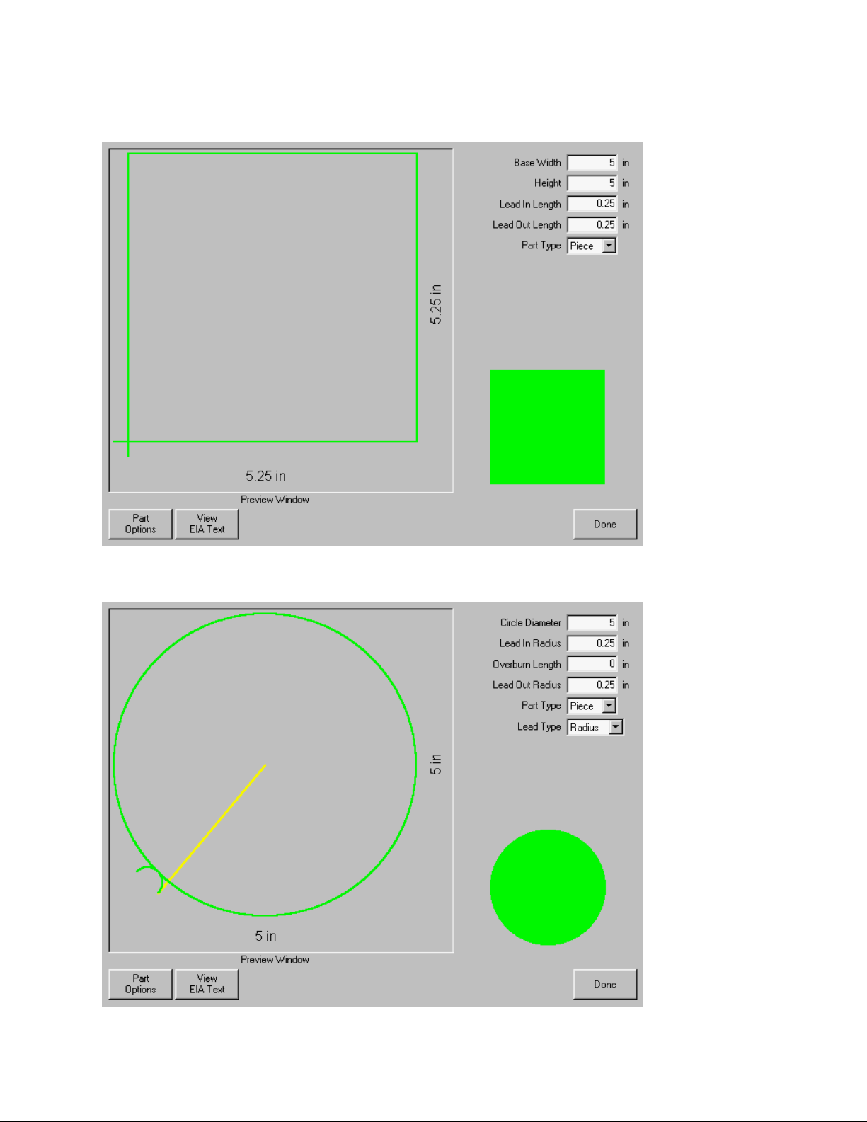
84 Operator’s Manual
Rectangle
Circle
Page 99
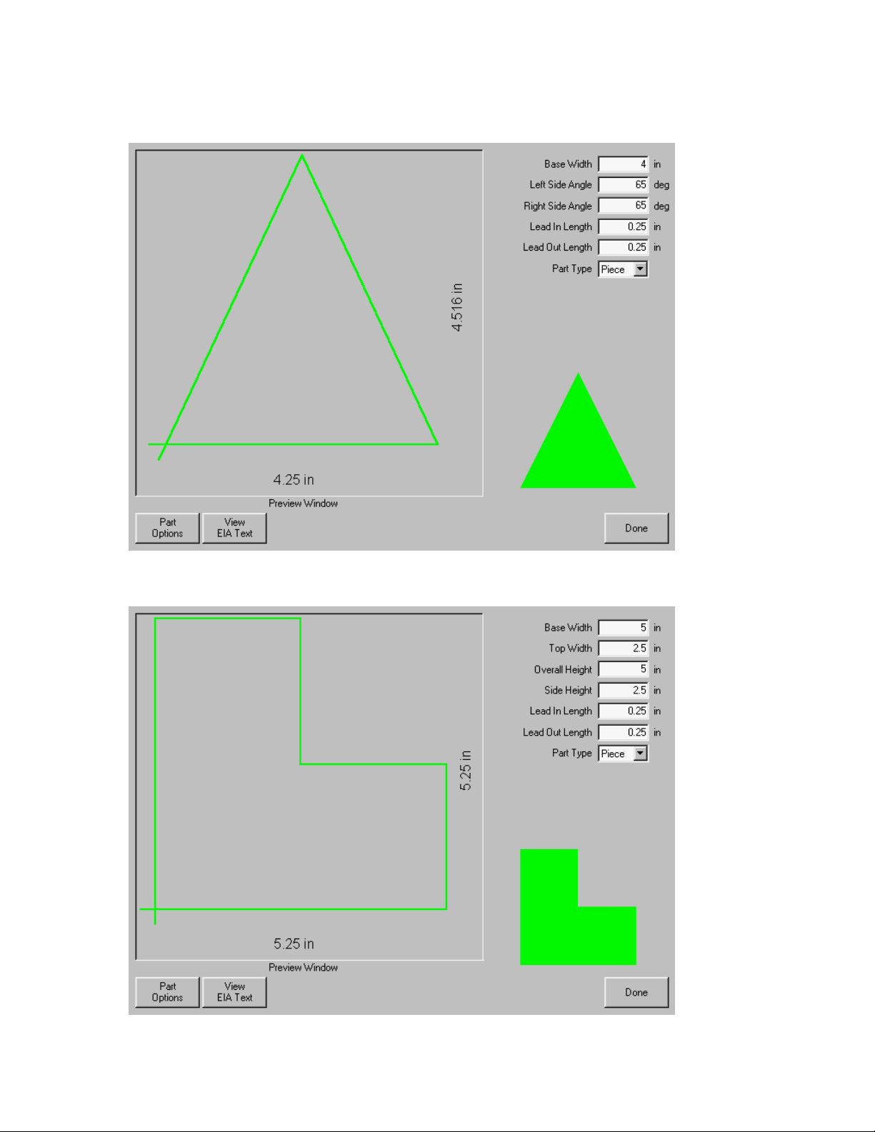
Section 6: Library Shapes 85
Triangle
L-Bracket
Page 100
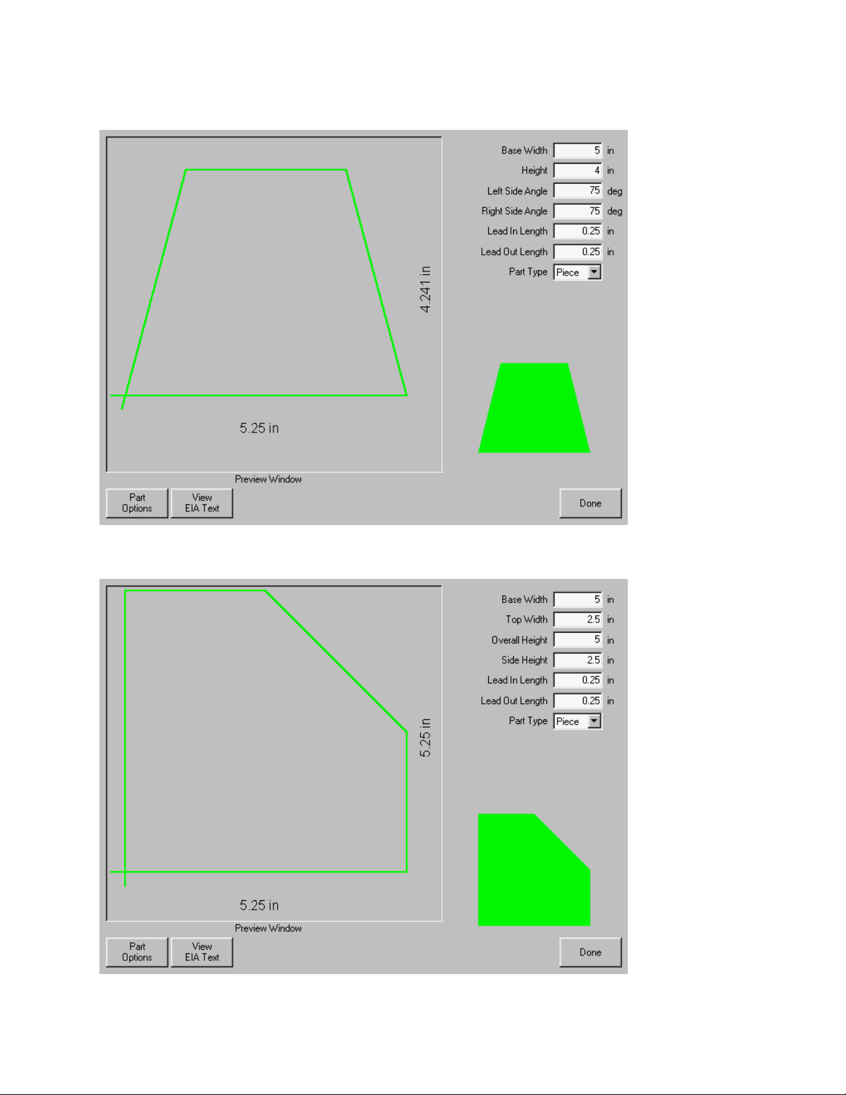
86 Operator’s Manual
Trapezoid
Slant Rectangle
 Loading...