

Page 1
Plasma Arc Cutting System
Instruction Manual
803580 - Revision 9
HySpeed
HT4400
®
™
Page 2
Page 3
Page 4

Page 5

Page 6

HT4400
Instruction Manual
(P/N 803580)
Revision 8 December, 2004
© Copyright 2004 Hypertherm, Inc.
All Rights Reserved
Hypertherm, HT, HySpeed and LongLife are trademarks of Hypertherm, Inc.,
and may be registered in the United States and/or other countries
Hypertherm, Inc.
Hanover, NH USA
www.hypertherm.com
Page 7

11/30/04
Hypertherm, Inc.
Etna Road, P.O. Box 5010
Hanover, NH 03755 USA
603-643-3441 Tel (Main Office)
603-643-5352 Fax (All Departments)
info@hypertherm.com (Main Office Email)
800-643-9878 Tel (Technical Service)
technical.service@hypertherm.com (Technical Service Email)
800-737-2978 Tel (Customer Service)
customer.service@hypertherm.com (Customer Service Email)
Hypertherm Automation, LLC
5 Technology Drive, Suite 300
West Lebanon, NH 03755 USA
603-298-7970 Tel
603-298-7977 Fax
Hypertherm Plasmatechnik, GmbH
Technologiepark Hanau
Rodenbacher Chaussee 6
D-63457 Hanau-Wolfgang, Deutschland
49 6181 58 2100 Tel
49 6181 58 2134 Fax
49 6181 58 2123 (Technical Service)
Hypertherm (S) Pte Ltd.
No. 19 Kaki Bukit Road 2
K.B. Warehouse Complex
Singapore 417847, Republic of Singapore
65 6 841 2489 Tel
65 6 841 2490 Fax
65 6 841 2489 (Technical Service)
Hypertherm (Shanghai) Consulting Co., Ltd.
Suite 305, CIMIC Towers
1090 Century Boulevard, Pudong
Shanghai 200120
P.R. China
86-21-5835-5362 /3 Tel
86-21-5835 5220 Fax
86-21-5835-5362 /3 (Technical Service)
Hypertherm
Branch of Hypertherm, UK, UC
PO Box 244
Wigan, Lancashire, England WN8 7WU
00 800 3324 9737 Tel
00 800 4973 7329 Fax
00 800 4973 7843 (Technical Service)
France
15 Impasse des Rosiers
95610 Eragny, France
00 800 3324 9737 Tel
00 800 4973 7329 Fax
Hypertherm S.r.l.
Via Torino 2
20123 Milano, Italia
39 02 725 46 312 Tel
39 02 725 46 400 Fax
39 02 725 46 314 (Technical Service)
Hypertherm Europe B.V.
Vaartveld 9
4704 SE Roosendaal, Nederland
31 165 596907 Tel
31 165 596901 Fax
31 165 596908 Tel (Marketing)
31 165 596900 Tel (Technical Service)
00 800 49 73 7843 Tel (Technical Service)
Japan
1952-14 Yata-Natsumegi
Mishima City, Shizuoka Pref.
411-0801 Japan
81 0 559 75 7387 Tel
81 0 559 75 7376 Fax
HYPERTHERM BRASIL LTDA.
Rua Jati, 33
CEP 07180-350 Cumbica
Guarulhos, SP - Brasil
55 11 6482 1087 Tel
55 11 6482 0591 Fax
Page 8

ELECTROMAGNETIC COMPATIBILITY (EMC)
EMC INTRODUCTION
Hypertherm's CE-marked equipment is built
in compliance with standard EN50199. The
equipment should be installed and used in
accordance with the information below to
achieve electromagnetic compatibility.
The limits required by EN50199 may not be
adequate to completely eliminate interference when the affected equipment is in
close proximity or has a high degree of
sensitivity. In such cases it may be necessary to use other measures to further
reduce interference.
This plasma equipment is designed for use
only in an industrial environment.
INSTALLATION AND USE
The user is responsible for installing and
using the plasma equipment according to
the manufacturer's instructions. If electromagnetic disturbances are detected then it
shall be the responsibility of the user to resolve the situation with the technical assistance of the manufacturer. In some cases
this remedial action may be as simple as
earthing the cutting circuit, see Earthing of
Workpiece. In other cases it could involve
constructing an electromagnetic screen
enclosing the power source and the work
complete with associated input filters. In all
cases electromagnetic disturbances must
be reduced to the point where they are no
longer troublesome.
ASSESSMENT OF AREA
Before installing the equipment the user
shall make an assessment of potential electromagnetic problems in the surrounding
area. The following shall be taken into
account:
a. Other supply cables, control cables,
signalling and telephone cables; above,
below and adjacent to the cutting equipment.
b. Radio and television transmitters and
receivers.
c. Computer and other control equipment.
d. Safety critical equipment, for example
guarding of industrial equipment.
e. Health of the people around, for
example the use of pacemakers and hearing aids.
f. Equipment used for calibration or measurement.
g. Immunity of other equipment in the environment. User shall ensure that other
equipment being used in the environment is
compatible. This may require additional
protection measures.
h. Time of day that cutting or other activities
are to be carried out.
Earthing of Workpiece
Where the workpiece is not bonded to earth
for electrical safety, nor connected to earth
because of its size and position, for example,
ship's hull or building steelwork, a connection
bonding the workpiece to earth may reduce
emissions in some, but not all instances.
Care should be taken to prevent the earthing
of the workpiece increasing the risk of injury
to users, or damage to other electrical equipment. Where necessary, the connection of
the workpiece to earth should be made by a
direct connection to the workpiece, but in
some countries where direct connection is
not permitted, the bonding should be
achieved by suitable capacitances selected
according to national regulations.
Note. The cutting circuit may or may not be
earthed for safety reasons. Changing the
earthing arrangements should only be authorized by a person who is competent to
assess whether the changes will increase
the risk of injury, for example, by allowing
parallel cutting current return paths which
may damage the earth circuits of other
equipment. Further guidance is given in IEC
TC26 (sec)94 and IEC TC26/108A/CD Arc
Welding Equipment Installation and Use.
Screening and Shielding
Selective screening and shielding of other
cables and equipment in the surrounding
area may alleviate problems of interference.
Screening of the entire plasma cutting
installation may be considered for special
applications.
The size of the surrounding area to be
considered will depend on the structure of
the building and other activities that are taking place. The surrounding area may extend
beyond the boundaries of the premises.
METHODS OF REDUCING EMISSIONS
Mains Supply
Cutting equipment must be connected to the
mains supply according to the manufacturer's recommendations. If interference
occurs, it may be necessary to take
additional precautions such as filtering of
the mains supply. Consideration should be
given to shielding the supply cable of permanently installed cutting equipment, in
metallic conduit or equivalent. Shielding
should be electrically continuous throughout
its length. The shielding should be connected to the cutting mains supply so that good
electrical contact is maintained between the
conduit and the cutting power source
enclosure.
Maintenance of Cutting Equipment
The cutting equipment must be routinely
maintained according to the manufacturer's
recommendations. All access and service
doors and covers should be closed and
properly fastened when the cutting
equipment is in operation. The cutting
equipment should not be modified in any
way except for those changes and adjustments covered in the manufacturer's
instructions. In particular, the spark gaps of
arc striking and stabilizing devices should
be adjusted and maintained according to
the manufacturer's recommendations.
Cutting Cables
The cutting cables should be kept as short
as possible and should be positioned close
together, running at or close to the floor
level.
Equipotential Bonding
Bonding of all metallic components in the
cutting installation and adjacent to it should
be considered. However, metallic components bonded to the workpiece will increase
the risk that the operator could receive a
shock by touching these metallic
components and the electrode at the same
time. The operator should be insulated from
all such bonded metallic components.
Hypertherm Plasma Systems i
Page 9

WARRANTY
ii Hypertherm Plasma Systems
9-01
WARNING
Genuine Hypertherm parts are the factory-recommended
replacement parts for your Hypertherm system. Any damage
caused by the use of other than genuine Hypertherm parts may
not be covered by the Hypertherm warranty.
WARNING
You are responsible for the safe use of the Product.
Hypertherm does not and cannot make any guarantee or
warranty regarding the safe use of the Product in your
environment.
GENERAL
Hypertherm, Inc. warrants that its Products shall be free from
defects in materials and workmanship, if Hypertherm is notified
of a defect (i) with respect to the power supply within a period
of two (2) years from the date of its delivery to you, with the
exception of Powermax Series power supplies, which shall be
within a period of three (3) years from the date of delivery to
you, and (ii) with respect to the torch and leads within a period
of one (1) year from its date of delivery to you. This warranty
shall not apply to any Product which has been incorrectly
installed, modified, or otherwise damaged. Hypertherm, at its
sole option, shall repair, replace, or adjust, free of charge, any
defective Products covered by this warranty which shall be
returned with Hypertherm’s prior authorization (which shall not
be unreasonably withheld), properly packed, to Hypertherm’s
place of business in Hanover, New Hampshire, or to an
authorized Hypertherm repair facility, all costs, insurance and
freight prepaid. Hypertherm shall not be liable for any repairs,
replacement, or adjustments of Products covered by this
warranty, except those made pursuant to this paragraph or with
Hypertherm’s prior written consent. The warranty above is
exclusive and is in lieu of all other warranties, express,
implied, statutory, or otherwise with respect to the
Products or as to the results which may be obtained
therefrom, and all implied warranties or conditions of
quality or of merchantability or fitness for a particular
purpose or against infringement. The foregoing shall
constitute the sole and exclusive remedy for any breach
by Hypertherm of its warranty. Distributors/OEMs may offer
different or additional warranties, but Distributors/OEMs are
not authorized to give any additional warranty protection to you
or make any representation to you purporting to be binding
upon Hypertherm.
PATENT INDEMNITY
Except only in cases of products not manufactured by
Hypertherm or manufactured by a person other than
Hypertherm not in strict conformity with Hypertherm’s
specifications and in cases of designs, processes, formulae, or
combinations not developed or purported to be developed by
Hypertherm, Hypertherm will defend or settle, at its own
expense, any suit or proceeding brought against you alleging
that the use of the Hypertherm product, alone and not in
combination with any other product not supplied by
Hypertherm, infringes any patent of any third party. You shall
notify Hypertherm promptly upon learning of any action or
threatened action in connection with any such alleged
infringement, and Hypertherm’s obligation to indemnify shall be
conditioned upon Hypertherm’s sole control of, and the
indemnified party’s cooperation and assistance in, the defense
of the claim.
LIMITATION OF LIABILITY
In no event shall Hypertherm be liable to any person or
entity for any incidental, consequential, indirect, or
punitive damages (including but not limited to lost profits)
regardless of whether such liability is based on breach of
contract, tort, strict liability, breach of warranties, failure of
essential purpose or otherwise and even if advised of the
possibility of such damages.
LIABILITY CAP
In no event shall Hypertherm’s liability, whether such
liability is based on breach of contract, tort, strict liability,
breach of warranties, failure of essential purpose or
otherwise, for any claim action suit or proceeding arising
out of or relating to the use of the Products exceed in the
aggregate the amount paid for the Products that gave rise
to such claim.
INSURANCE
At all times you will have and maintain insurance in such
quantities and types, and with coverage sufficient and
appropriate to defend and to hold Hypertherm harmless in
the event of any cause of action arising from the use of the
Products.
NATIONAL AND LOCAL CODES
National and Local codes governing plumbing and electrical
installation shall take precedent over any instructions
contained in this manual. In no event shall Hypertherm be
liable for injury to persons or property damage by reason of any
code violation or poor work practices.
TRANSFER OF RIGHTS
You may transfer any remaining rights you may have
hereunder only in connection with the sale of all or substantially
all of your assets or capital stock to a successor in interest who
agrees to be bound by all of the terms and conditions of this
Warranty.
Page 10

HT4400 Instruction Manual iii
TABLE OF CONTENTS
Electromagnetic Compatibility (EMC)..................................................................................................................i
Warranty .............................................................................................................................................................ii
Section 1 Safety ............................................................................................................................................1-1
Recognize Safety Information.........................................................................................................................1-2
Follow Safety Instructions ...............................................................................................................................1-2
Cutting Can Cause Fire or Explosion..............................................................................................................1-2
Electric Shock Can Kill....................................................................................................................................1-3
Cutting Can Produce Toxic Fumes..................................................................................................................1-3
A Plasma Arc Can Cause Injury and Burns.....................................................................................................1-4
Arc Rays Can Burn Eyes and Skin .................................................................................................................1-4
Grounding Safety ............................................................................................................................................1-4
Compressed Gas Equipment Safety...............................................................................................................1-5
Gas Cylinders Can Explode If Damaged ........................................................................................................1-5
Noise Can Damage Hearing ...........................................................................................................................1-5
Pacemaker and Hearing Aid Operation...........................................................................................................1-5
A Plasma Arc Can Damage Frozen Pipes ......................................................................................................1-5
Additional Safety Information ..........................................................................................................................1-5
Warning Label.................................................................................................................................................1-6
Section 1a Sécurité ......................................................................................................................................1a-1
Identifier les consignes de sécurité...............................................................................................................1a-2
Suivre les instructions de sécurité.................................................................................................................1a-2
Le coupage peut provoquer un incendie ou une explosion...........................................................................1a-2
Les chocs électriques peuvent être fatals.....................................................................................................1a-3
Le coupage peut produire des vapeurs toxiques ..........................................................................................1a-3
L'arc plasma peut provoquer des blessures ou des brûlures........................................................................1a-4
Mise à la masse et à la terre.........................................................................................................................1a-4
Les rayons de l'arc peuvent brûler les yeux et la peau .................................................................................1a-4
Sécurité des bouteilles de gaz comprimé .....................................................................................................1a-5
Les bouteilles de gaz comprimé peuvent exploser en cas de dommages....................................................1a-5
Le bruit peut provoquer des problèmes auditifs............................................................................................1a-5
Pacemakers et prothéses auditives ..............................................................................................................1a-5
Étiquette de sécurité .....................................................................................................................................1a-6
Section 2 Specifications ............................................................................................................................2-1
System Components.......................................................................................................................................2-2
Power Supply ........................................................................................................................................2-2
Machine Torch ........................................................................................................................................2-2
Valve Cluster ..........................................................................................................................................2-2
Gas Console...........................................................................................................................................2-2
Ignition Console......................................................................................................................................2-2
Cooler.....................................................................................................................................................2-2
Remote Current Control Console - Optional...........................................................................................2-2
Command THC - Optional......................................................................................................................2-2
Specifications..................................................................................................................................................2-3
System Requirements ............................................................................................................................2-3
Power Supply .........................................................................................................................................2-4
7
Page 11

TABLE OF CONTENTS
Machine Torch .......................................................................................................................................2-5
Valve Cluster ..........................................................................................................................................2-5
Gas Console...........................................................................................................................................2-6
Ignition Console......................................................................................................................................2-7
Cooler.....................................................................................................................................................2-8
Remote Current Control Console - Optional...........................................................................................2-9
Command THC - Optional......................................................................................................................2-9
Section 3 Installation ..................................................................................................................................3-1
Installation Requirements................................................................................................................................3-2
Gas Requirements ..........................................................................................................................................3-2
Gas Supply Plumbing......................................................................................................................................3-2
Torch Coolant Requirements...........................................................................................................................3-3
Water Purity Requirements for Coolant Mixture..............................................................................................3-4
Grounding Requirements................................................................................................................................3-4
Fume Emissions..............................................................................................................................................3-4
Noise Levels....................................................................................................................................................3-5
Power Requirements.......................................................................................................................................3-5
Connecting the Power.....................................................................................................................................3-6
Torch Lifter Requirement.................................................................................................................................3-8
System Units Placement.................................................................................................................................3-8
HT4400 System Interconnections ................................................................................................................3-11
Ignition Console Connections - 1 of 3 ...........................................................................................................3-12
Ignition Console Connections - 2 of 3 ...........................................................................................................3-13
Ignition Console Connections - 3 of 3 ...........................................................................................................3-14
Gas Console Connections - 1 of 3 ................................................................................................................3-15
Gas Console Connections - 2 of 3 ................................................................................................................3-16
Gas Console Connections - 3 of 3 ................................................................................................................3-17
Cooler Connections - 1 of 2 ..........................................................................................................................3-18
Cooler Connections - 2 of 2 ..........................................................................................................................3-19
Remote Current Control Connection.............................................................................................................3-20
Machine Interface Connections - 1 of 2 ........................................................................................................3-20
Machine Interface Connections - 2 of 2 ........................................................................................................3-21
Work Table Connection .................................................................................................................................3-22
Power Supply #2 Connection........................................................................................................................3-22
Torch Connections ........................................................................................................................................3-23
Torch Mounting and Alignment......................................................................................................................3-24
Post-Installation.............................................................................................................................................3-25
Section 4 Operation ....................................................................................................................................4-1
Controls and Indicators ...................................................................................................................................4-2
Gas Console...........................................................................................................................................4-2
Gas Console Controls and Indicators.....................................................................................................4-3
Status Display Messages on the Gas Console ......................................................................................4-4
Power Supply ........................................................................................................................................4-4
Power Supply ........................................................................................................................................4-5
Remote Current Control Console ...........................................................................................................4-5
iv HT4400 Instruction Manual
7
Page 12

HT4400 Instruction Manual v
TABLE OF CONTENTS
Leak Tests .......................................................................................................................................................4-6
Daily Startup....................................................................................................................................................4-8
Common Cutting Faults ................................................................................................................................4-12
Performance and Process Data....................................................................................................................4-13
Cut Chart and Consumable Parts Index .......................................................................................................4-14
Cut Charts.....................................................................................................................................................4-15
Changing Consumable Parts ........................................................................................................................4-23
Remove Consumables .........................................................................................................................4-23
Inspect Consumables...........................................................................................................................4-24
Inspect Torch ........................................................................................................................................4-25
Inspect Electrode Pit Depth..................................................................................................................4-26
Install Consumables .............................................................................................................................4-27
Replace Torch Water Tube............................................................................................................................4-28
Cutting Techniques........................................................................................................................................4-29
How to Get Better Cut Quality ..............................................................................................................4-29
How to Get Longer Consumable Life ...................................................................................................4-30
How to Get Better Pierces....................................................................................................................4-32
How to Increase Cutting Speed............................................................................................................4-32
Section 5 Maintenance ..............................................................................................................................5-1
Introduction .....................................................................................................................................................5-2
Routine Maintenance ......................................................................................................................................5-2
Replacing the Cooler Filter..............................................................................................................................5-3
Pump Strainer Cleaning..................................................................................................................................5-3
Torch Coolant Draining....................................................................................................................................5-4
Cooler Draining ...............................................................................................................................................5-4
HT4400 Startup Sequence..............................................................................................................................5-5
HT4400 Plasma START Sequence.................................................................................................................5-6
HT4400 Plasma RUN Sequence ....................................................................................................................5-7
Error Code Troubleshooting - 1 of 3................................................................................................................5-8
Error Code Troubleshooting - 2 of 3................................................................................................................5-9
Error Code Troubleshooting - 3 of 3..............................................................................................................5-10
System Troubleshooting - 1 of 4....................................................................................................................5-11
System Troubleshooting - 2 of 4 ...................................................................................................................5-12
System Troubleshooting - 3 of 4 ...................................................................................................................5-13
System Troubleshooting - 4 of 4 ...................................................................................................................5-14
Initial Checks.................................................................................................................................................5-15
Power Measurement Location - All Voltages.................................................................................................5-16
Power Distribution PCB1 - Status Indicators.................................................................................................5-17
Microprocessor Control Board PCB2 - Status Indicators..............................................................................5-18
Analog Board PCB3 - Status Indicators........................................................................................................5-19
Current Sense Test .......................................................................................................................................5-20
Relay Board PCB4 - Status Indicators..........................................................................................................5-21
Serial I/O Board PCB5 - Status Indicators ....................................................................................................5-24
Start Circuit Board PCB14 - Status Indicators and Operation.......................................................................5-29
Pilot Arc Current Levels........................................................................................................................5-29
Start Circuit Functional Schematic .......................................................................................................5-30
7
Page 13

vi HT4400 Instruction Manual
TABLE OF CONTENTS
Start Circuit Troubleshooting................................................................................................................5-30
Phase Loss Detection Board PCB21 - Status Indicators and Operation .....................................................5-31
Chopper Module Test Procedure .................................................................................................................5-32
Coolant Flow Test..........................................................................................................................................5-34
Pressure Switch Settings ..............................................................................................................................5-36
Gas Console Valve Select Switch Detail.......................................................................................................5-37
Preventative Maintenance.............................................................................................................................5-38
Section 6 Parts List ....................................................................................................................................6-1
Power Supply..................................................................................................................................................6-2
Front Panel Outside................................................................................................................................6-2
Power Supply..................................................................................................................................................6-3
Front Panel Inside ..................................................................................................................................6-3
Power Supply..................................................................................................................................................6-4
Front Bail (Wall)......................................................................................................................................6-4
Power Supply..................................................................................................................................................6-5
Rear Bail (Wall) ......................................................................................................................................6-5
Power Supply..................................................................................................................................................6-6
Rear Panel Inside and Outside...............................................................................................................6-6
Ignition Console ..............................................................................................................................................6-7
Gas Console ...................................................................................................................................................6-8
Cooler..............................................................................................................................................................6-9
HT4400 Torch................................................................................................................................................6-10
Consumable Configurations..........................................................................................................................6-11
Consumable Parts Kit ...................................................................................................................................6-12
Counterclockwise Consumables...................................................................................................................6-12
Valve Cluster Assembly ................................................................................................................................6-13
Recommended Spare Parts..........................................................................................................................6-13
Electrode Pit Depth Gauge Assembly ..........................................................................................................6-14
Section 7 Wiring Diagrams ........................................................................................................................7-1
Introduction .....................................................................................................................................................7-1
Wiring Diagram Symbols.................................................................................................................................7-1
Appendix A System Grounding ................................................................................................................a-1
System Grounding Requirements...................................................................................................................a-1
Suggested Ground Cable Routing ..................................................................................................................a-1
Power Supply .........................................................................................................................................a-1
Equipment Grounding.............................................................................................................................a-1
Work Table Grounding ............................................................................................................................a-2
Appendix B Propylene Glycol & Benzotriazole Safety Data ..................................................................b-1
Appendix C Gas Regulators ......................................................................................................................c-1
Appendix D Noise Levels ..........................................................................................................................d-1
Appendix E O2/N2 Cutcharts @ 140 PSI ..................................................................................................e-1
Appendix F O2/N2 Cutcharts @ 120 PSI....................................................................................................f-1
8
Page 14

HYPERTHERM Plasma Systems 1-1
Section 1
SAFETY
In this section:
Recognize Safety Information.........................................................................................................................1-2
Follow Safety Instructions ...............................................................................................................................1-2
Cutting Can Cause Fire or Explosion..............................................................................................................1-2
Electric Shock Can Kill....................................................................................................................................1-3
Cutting Can Produce Toxic Fumes..................................................................................................................1-3
A Plasma Arc Can Cause Injury and Burns.....................................................................................................1-4
Arc Rays Can Burn Eyes and Skin .................................................................................................................1-4
Grounding Safety ............................................................................................................................................1-4
Compressed Gas Equipment Safety...............................................................................................................1-5
Gas Cylinders Can Explode If Damaged ........................................................................................................1-5
Noise Can Damage Hearing ...........................................................................................................................1-5
Pacemaker and Hearing Aid Operation...........................................................................................................1-5
A Plasma Arc Can Damage Frozen Pipes ......................................................................................................1-5
Additional Safety Information ..........................................................................................................................1-5
Warning Label.................................................................................................................................................1-6
Page 15
SAFETY
1-2 HYPERTHERM Plasma Systems
11-98
SAFETY
RECOGNIZE SAFETY INFORMATION
The symbols shown in this section are used to
identify potential hazards. When you see a safety
symbol in this manual or on your machine, understand
the potential for personal injury, and follow the related
instructions to avoid the hazard.
FOLLOW SAFETY INSTRUCTIONS
Read carefully all safety messages in this manual and
safety labels on your machine.
• Keep the safety labels on your machine in good
condition. Replace missing or damaged labels
immediately.
• Learn how to operate the machine and how to use
the controls properly. Do not let anyone operate it
without instruction.
• Keep your machine in proper working condition.
Unauthorized modifications to the machine may
affect safety and machine service life.
DANGER WARNING CAUTION
A signal word DANGER or WARNING is used with a
safety symbol. DANGER identifies the most serious
hazards.
• DANGER and WARNING safety labels are located
on your machine near specific hazards.
• WARNING safety messages precede related
instructions in this manual that may result in injury
or death if not followed correctly.
• CAUTION safety messages precede related
instructions in this manual that may result in
damage to equipment if not followed correctly.
Fire Prevention
• Be sure the area is safe before doing any cutting.
Keep a fire extinguisher nearby.
• Remove all flammables within 35 feet (10 m) of the
cutting area.
• Quench hot metal or allow it to cool before handling
or before letting it touch combustible materials.
• Never cut containers with potentially flammable
materials inside – they must be emptied and
properly cleaned first.
• Ventilate potentially flammable atmospheres before
cutting.
• When cutting with oxygen as the plasma gas, an
exhaust ventilation system is required.
Explosion Prevention
• Do not use the plasma system if explosive dust or
vapors may be present.
• Do not cut pressurized cylinders, pipes, or any
closed container.
• Do not cut containers that have held combustible
materials.
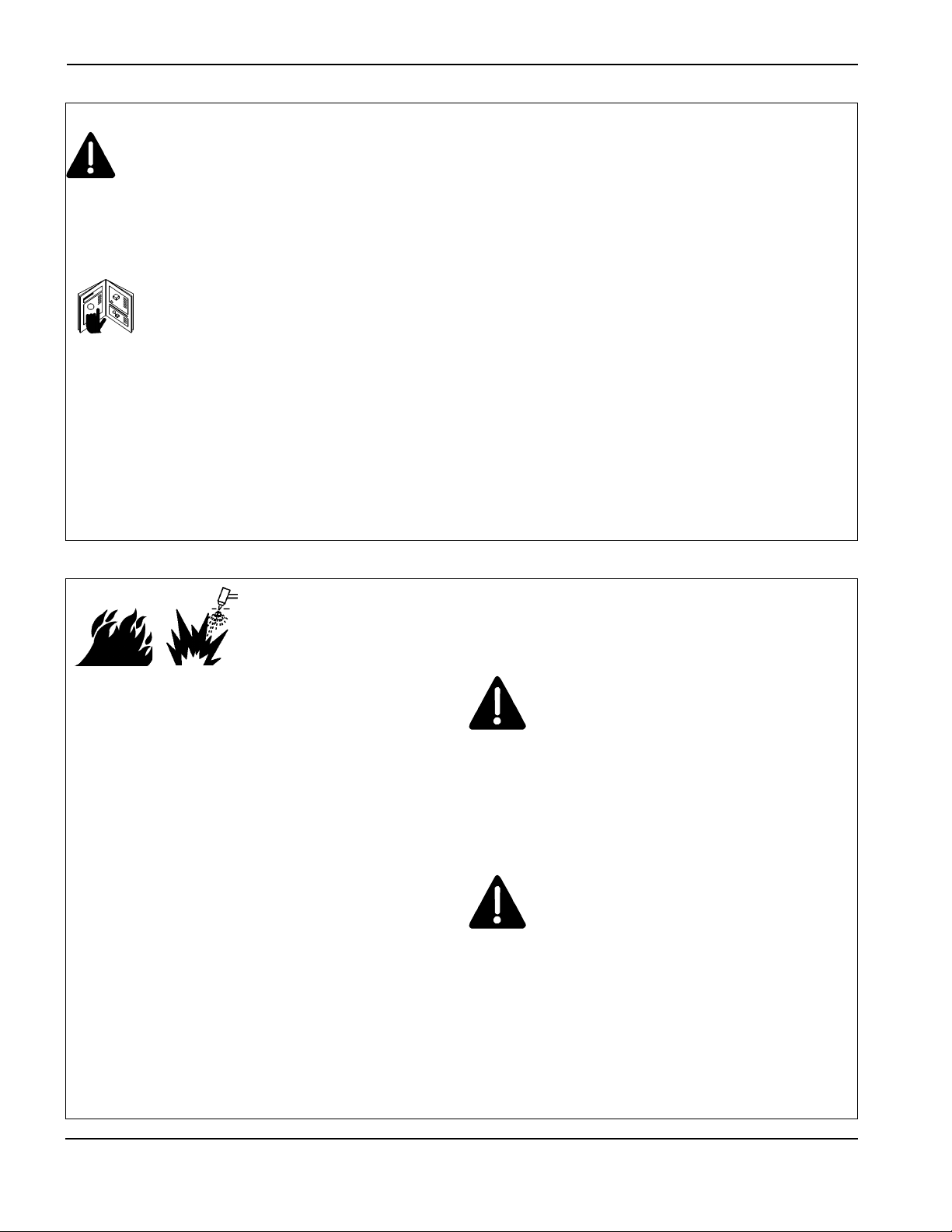
CUTTING CAN CAUSE FIRE OR EXPLOSION
WARNING
Explosion Hazard
Argon-Hydrogen and Methane
Hydrogen and methane are flammable gases that
present an explosion hazard. Keep flames away from
cylinders and hoses that contain methane or hydrogen
mixtures. Keep flames and sparks away from the torch
when using methane or argon-hydrogen plasma.
WARNING
Hydrogen Detonation with Aluminum Cutting
• When cutting aluminum underwater, or with the
water touching the underside of the aluminum, free
hydrogen gas may collect under the workpiece and
detonate during plasma cutting operations.
• Install an aeration manifold on the floor of the water
table to eliminate the possibility of hydrogen
detonation. Refer to the Appendix section of this
manual for aeration manifold details.
Page 16

Touching live electrical parts can cause a fatal shock
or severe burn.
• Operating the plasma system completes an
electrical circuit between the torch and the
workpiece. The workpiece and anything touching
the workpiece are part of the electrical circuit.
• Never touch the torch body, workpiece or the water
in a water table when the plasma system is
operating.
Electric Shock Prevention
All Hypertherm plasma systems use high voltage
in the cutting process (200 to 400 VDC are
common). Take the following precautions when
operating this system:
• Wear insulated gloves and boots, and keep your
body and clothing dry.
• Do not stand, sit or lie on – or touch – any wet
surface when using the plasma system.
• Insulate yourself from work and ground using dry
insulating mats or covers big enough to prevent any
physical contact with the work or ground. If you must
work in or near a damp area, use extreme caution.
• Provide a disconnect switch close to the power
supply with properly sized fuses. This switch allows
the operator to turn off the power supply quickly in
an emergency situation.
• When using a water table, be sure that it is correctly
connected to earth ground.
ELECTRIC SHOCK CAN KILL
• Install and ground this equipment according to the
instruction manual and in accordance with national
and local codes.
• Inspect the input power cord frequently for damage
or cracking of the cover. Replace a damaged power
cord immediately. Bare wiring can kill.
• Inspect and replace any worn or damaged torch
leads.
• Do not pick up the workpiece, including the waste
cutoff, while you cut. Leave the workpiece in place
or on the workbench with the work cable attached
during the cutting process.
• Before checking, cleaning or changing torch parts,
disconnect the main power or unplug the power
supply.
• Never bypass or shortcut the safety interlocks.
• Before removing any power supply or system
enclosure cover, disconnect electrical input power.
Wait 5 minutes after disconnecting the main power
to allow capacitors to discharge.
• Never operate the plasma system unless the power
supply covers are in place. Exposed power supply
connections present a severe electrical hazard.
• When making input connections, attach proper
grounding conductor first.
• Each Hypertherm plasma system is designed to be
used only with specific Hypertherm torches. Do not
substitute other torches which could overheat and
present a safety hazard.
Cutting can produce toxic fumes and gases that
deplete oxygen and cause injury or death.
• Keep the cutting area well ventilated or use an
approved air-supplied respirator.
• Do not cut in locations near degreasing, cleaning or
spraying operations. The vapors from certain
chlorinated solvents decompose to form phosgene
gas when exposed to ultraviolet radiation.
• Do not cut metal coated or containing toxic materials, such as zinc (galvanized), lead, cadmium or
CUTTING CAN PRODUCE TOXIC FUMES
beryllium, unless the area is well ventilated and the
operator wears an air-supplied respirator. The
coatings and any metals containing these elements
can produce toxic fumes when cut.
• Never cut containers with potentially toxic materials
inside – they must be emptied and properly cleaned
first.
• This product, when used for welding or cutting,
produces fumes or gases which contain chemicals
known to the State of California to cause birth
defects and, in some cases, cancer.
HYPERTHERM Plasma Systems 1-3
8-99
SAFETY
Page 17
SAFETY
1-4 HYPERTHERM Plasma Systems
4-99
SAFETY
Instant-On Torches
Plasma arc comes on immediately when the torch
switch is activated.
A PLASMAARC CAN CAUSE INJURY AND BURNS
The plasma arc will cut quickly through gloves and
skin.
• Keep away from the torch tip.
• Do not hold metal near the cutting path.
• Never point the torch toward yourself or others.
Eye Protection Plasma arc rays produce intense
visible and invisible (ultraviolet and infrared) rays that
can burn eyes and skin.
• Use eye protection in accordance with applicable
national or local codes.
• Wear eye protection (safety glasses or goggles with
side shields, or a welding helmet) with appropriate
lens shading to protect your eyes from the arc’s
ultraviolet and infrared rays.
Lens Shade
Arc Current AWS (USA) ISO 4850
Up to 100 A No. 8 No. 11
100-200 A No. 10 No. 11-12
200-400 A No. 12 No. 13
Over 400 A No. 14 No. 14
ARC RAYS CAN BURN EYES AND SKIN
Skin Protection Wear protective clothing to protect
against burns caused by ultraviolet light, sparks and
hot metal.
• Gauntlet gloves, safety shoes and hat.
• Flame-retardant clothing to cover all exposed areas.
• Cuffless trousers to prevent entry of sparks and
slag.
• Remove any combustibles, such as a butane lighter
or matches, from your pockets before cutting.
Cutting Area Prepare the cutting area to reduce
reflection and transmission of ultraviolet light:
• Paint walls and other surfaces with dark colors to
reduce reflection.
• Use protective screens or barriers to protect others
from flash and glare.
• Warn others not to watch the arc. Use placards or
signs.
Work Cable Attach the work cable securely to the
workpiece or the work table with good metal-to-metal
contact. Do not connect it to the piece that will fall
away when the cut is complete.
Work Table Connect the work table to an earth
ground, in accordance with appropriate national or
local electrical codes.
GROUNDING SAFETY
Input Power
• Be sure to connect the power cord ground wire to
the ground in the disconnect box.
• If installation of the plasma system involves
connecting the power cord to the power supply, be
sure to connect the power cord ground wire
properly.
• Place the power cord's ground wire on the stud first,
then place any other ground wires on top of the
power cord ground. Fasten the retaining nut tightly.
• Tighten all electrical connections to avoid excessive
heating.
Page 18
SAFETY
HYPERTHERM Plasma Systems 1-5
11-98
SAFETY
• Never lubricate cylinder valves or regulators with oil
or grease.
• Use only correct gas cylinders, regulators, hoses
and fittings designed for the specific application.
• Maintain all compressed gas equipment and
associated parts in good condition.
• Label and color-code all gas hoses to identify the
type of gas in each hose. Consult applicable
national or local codes.
GAS CYLINDERS CAN
EXPLODE IF DAMAGED
COMPRESSED GAS EQUIPMENT SAFETY
Gas cylinders contain gas under high pressure. If
damaged, a cylinder can explode.
• Handle and use compressed gas cylinders in
accordance with applicable national or local codes.
• Never use a cylinder that is not upright and secured
in place.
• Keep the protective cap in place over valve except
when the cylinder is in use or connected for use.
• Never allow electrical contact between the plasma
arc and a cylinder.
• Never expose cylinders to excessive heat, sparks,
slag or open flame.
• Never use a hammer, wrench or other tool to open
a stuck cylinder valve.
Prolonged exposure to noise from cutting or gouging
can damage hearing.
• Use approved ear protection when using plasma
system.
• Warn others nearby about the noise hazard.
NOISE CAN DAMAGE HEARING
Pacemaker and hearing aid operation can be affected
by magnetic fields from high currents.
Pacemaker and hearing aid wearers should consult a
doctor before going near any plasma arc cutting and
gouging operations.
To reduce magnetic field hazards:
• Keep both the work cable and the torch lead to one
side, away from your body.
• Route the torch leads as close as possible to the
work cable.
• Do not wrap or drape the torch lead or work cable
around your body.
• Keep as far away from the power supply as
possible.
PACEMAKER AND HEARING
AID OPERATION
ADDITIONAL SAFETY INFORMATION
1. ANSI Standard Z49.1, Safety in Welding and Cutting, American
Welding Society, 550 LeJeune Road
P.O. Box 351020, Miami, FL 33135
2. ANSI Standard Z49.2, Fire Prevention in the Use of Cutting and
Welding Processes, American National Standards Institute
1430 Broadway, New York, NY 10018
3. ANSI Standard Z87.1, Safe Practices for Occupation and
Educational Eye and Face Protection, American National
Standards Institute, 1430 Broadway, New York, NY 10018
4. AWS F4.1, Recommended Safe Practices for the Preparation for
Welding and Cutting of Containers and Piping That Have Held
Hazardous Substances, American Welding Society
550 LeJeune Road, P.O. Box 351040, Miami, FL 33135
5. AWS F5.2, Recommended Safe Practices for Plasma Arc
Cutting, American Welding Society
550 LeJeune Road, P.O. Box 351040, Miami, FL 33135
6. CGA Pamphlet P-1, Safe Handling of Compressed Gases in
Cylinders, Compressed Gas Association
1235 Jefferson Davis Highway, Arlington, VA 22202
7. CSA Standard W117.2, Code for Safety in Welding and Cutting,
Canadian Standards Association Standard Sales
178 Rexdale Boulevard, Rexdale, Ontario M9W 1R3, Canada
8. NFPA Standard 51B, Cutting and Welding Processes, National
Fire Protection Association
470 Atlantic Avenue, Boston, MA 02210
9. NFPA Standard 70–1978, National Electrical Code, National Fire
Protection Association, 470 Atlantic Avenue, Boston, MA 02210
10. OSHA, Safety and Health Standards, 29FR 1910
U.S. Government Printing Office, Washington, D.C. 20402
A PLASMA ARC CAN
DAMAGE FROZEN PIPES
Frozen pipes may be damaged or can burst if you
attempt to thaw them with a plasma torch.
Page 19
SAFETY
1-6 HYPERTHERM Plasma Systems
8-99
SAFETY
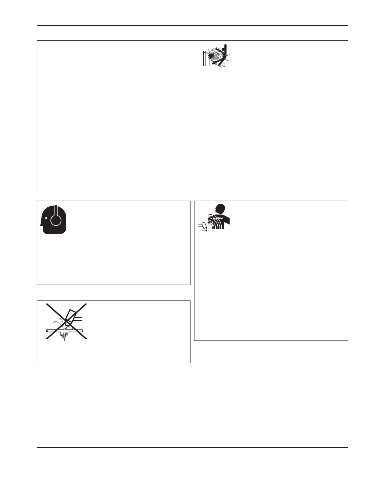
WARNING LABEL
This warning label is affixed to some power supplies. It is
important that the operator and maintenance technician
understand the intent of these warning symbols as described.
The numbered text corresponds to the numbered boxes on
the label.
1. Cutting sparks can cause explosion or fire.
1.1 Keep flammables away from cutting.
1.2 Keep a fire extinguisher nearby, and have
a watchperson ready to use it.
1.3 Do not cut on any closed containers.
2. The plasma arc can cause injury and
burns.
2.1 Turn off power before disassembling torch.
2.2 Do not hold the material near cutting path.
2.3 Wear complete body protection.
3. Electric shock from torch or wiring can kill.
Protect yourself from electric shock.
3.1 Wear insulating gloves. Do not wear wet or
damaged gloves.
3.2 Insulate yourself from work and ground.
3.3 Disconnect input plug or power before
working on machine.
4. Breathing cutting fumes can be hazardous
to your health.
4.1 Keep your head out of the fumes.
4.2 Use forced ventilation or local exhaust to
remove the fumes.
4.3 Use ventilating fan to remove the fumes.
5. Arc rays can burn eyes and injure skin.
5.1 Wear hat and safety glasses. Use ear
protection and button shirt collar. Use
welding helmet with correct shade of filter.
Wear complete body protection.
6. Become trained and read the instructions
before working on the machine or cutting.
7. Do not remove or paint over (cover)
warning labels.
110212
Page 20

Hypertherm Systèmes plasma 1a-1
2/12/01
Section 1a
SÉCURITÉ
Dans cette section :
Identifier les consignes de sécurité.........................................................................................................................1a-2
Suivre les instructions de sécurité ..........................................................................................................................1a-2
Danger Avertissement Précaution ........................................................................................................................1a-2
Le coupage peut provoquer un incendie ou une explosion ....................................................................................1a-2
Prévention des incendies, Prévention des explosions...................................................................................1a-2
Risque d’explosion argon-hydrogène et méthane..........................................................................................1a-2
Détonation de l’hydrogène lors du coupage de l’aluminium...........................................................................1a-2
Les chocs électriques peuvent être fatals...............................................................................................................1a-3
Prévention des chocs électriques ..................................................................................................................1a-3
Le coupage peut produire des vapeurs toxiques....................................................................................................1a-3
L’arc plasma peut provoquer des blessures ou des brûlures .................................................................................1a-4
Torches à allumage instantané ......................................................................................................................1a-4
Les rayons de l’arc peuvent brûler les yeux et la peau...........................................................................................1a-4
Protection des yeux, Protection de la peau, Zone de coupage ....................................................................1a-4
Mise à la masse et à la terre...................................................................................................................................1a-4
Câble de retour, Table de travail, Alimentation...............................................................................................1a-4
Sécurité des bouteilles de gaz comprimé ...............................................................................................................1a-5
Les bouteilles de gaz comprimé peuvent exploser en cas de dommages .............................................................1a-5
Le bruit peut provoquer des problèmes auditifs......................................................................................................1a-5
Pacemakers et prothèses auditives........................................................................................................................1a-5
Un arc plasma peut endommager les tuyaux gelés................................................................................................1a-5
Étiquette de sécurité ...............................................................................................................................................1a-6
Page 21

SÉCURITÉ
1a-2 Hypertherm Systèmes plasma
2/12/01
IDENTIFIER LES CONSIGNES
DE SÉCURITÉ
Les symboles indiqués dans cette section sont utilisés pour
identifier les risques éventuels. Si vous trouvez un symbole
de sécurité, que ce soit dans ce manuel ou sur
l’équipement, soyez conscient des risques de blessures et
suivez les instructions correspondantes afin d’éviter ces
risques.
SUIVRE LES INSTRUCTIONS
DE SÉCURITÉ
Lire attentivement toutes les consignes de sécurité dans le
présent manuel et sur les étiquettes de sécurité se trouvant
sur la machine.
• Les étiquettes de sécurité doivent rester lisibles.
Remplacer immédiatement les étiquettes manquantes ou
abîmées.
• Apprendre à faire fonctionner la machine et à utiliser
correctement les commandes. Ne laisser personne utiliser
la machine sans connaître son fonctionnement.
• Garder la machine en bon état. Des modifications non
autorisées sur la machine peuvent engendrer des
problèmes de sécurité et raccourcir la durée d’utilisation
de l’équipement.
DANGER AVERTISSEMENT PRÉCAUTION
Les signaux DANGER ou AVERTISSEMENT sont utilisés
avec un symbole de sécurité, DANGER correspondant aux
risques les plus sérieux.
• Les étiquettes de sécurité DANGER et AVERTISSEMENT
sont situées sur la machine pour signaler certains
dangers spécifiques.
• Les messages d’AVERTISSEMENT précèdent les
instructions d’utilisation expliquées dans ce manuel et
signalent les risques de blessures ou de mort au cas où
ces instructions ne seraient pas suivies correctement.
• Les messages de PRÉCAUTION précèdent les
instructions d’utilisation contenues dans ce manuel et
signalent que le matériel risque d’être endommagé si les
instructions ne sont pas suivies correctement.
Prévention des incendies
• Avant de commencer, s’assurer que la zone de coupage
ne présente aucun danger. Conserver un extincteur à
proximité.
• Éloigner toute matière inflammable à une distance d’au
moins 10 m du poste de coupage.
• Tremper le métal chaud ou le laisser refroidir avant de
le manipuler ou avant de le mettre en contact avec des
matériaux combustibles.
• Ne jamais couper des récipients pouvant contenir des
matières inflammables avant de les avoir vidés et
nettoyés correctement.
• Aérer toute atmosphère potentiellement inflammable
avant d’utiliser un système plasma.
• Lors de l’utilisation d’oxygène comme gaz plasma, un
système de ventilation par aspiration est nécessaire.
Prévention des explosions
• Ne pas couper en présence de poussière ou de vapeurs.
• Ne pas couper de bouteilles, de tuyaux ou autres
récipients fermés et pressurisés.
• Ne pas couper de récipients contenant des matières
combustibles.
LE COUPAGE PEUT PROVOQUER UN INCENDIE
OU UNE EXPLOSION
AVERTISSEMENT
Risque d’explosion
argon-hydrogène et méthane
L’hydrogène et le méthane sont des gaz inflammables et
potentiellement explosifs. Conserver à l’écart de toute
flamme les bouteilles et tuyaux contenant des mélanges à
base d’hydrogène ou de méthane. Maintenir toute flamme
et étincelle à l’écart de la torche lors de l’utilisation d’un
plasma d’argon-hydrogène ou de méthane.
AVERTISSEMENT
Détonation de l’hydrogène lors du
coupage de l’aluminium
• Lors du coupage de l’aluminium sous l’eau, ou si l’eau
touche la partie inférieure de la pièce d’aluminium, de
l’hydrogène libre peut s’accumuler sous la pièce à couper
et détonner lors du coupage plasma.
• Installer un collecteur d’aération au fond de la table à eau
afin d’éliminer les risques de détonation de l’hydrogène.
Se référer à l’annexe du manuel pour plus de
renseignements sur les collecteurs d’aération.
Page 22

SÉCURITÉ
Hypertherm Systèmes plasma 1a-3
2/12/01
Toucher une pièce électrique sous tension peut provoquer
un choc électrique fatal ou des brûlures graves.
• La mise en fonctionnement du système plasma ferme un
circuit électrique entre la torche et la pièce à couper. La
pièce à couper et tout autre élément en contact avec cette
pièce font partie du circuit électrique.
• Ne jamais toucher le corps de la torche, la pièce à couper
ou l’eau de la table à eau pendant le fonctionnement du
système plasma.
Prévention des chocs électriques
Tous les systèmes plasma Hypertherm utilisent des hautes
tensions pour le coupage (souvent de 200 à 400 V). On
doit prendre les précautions suivantes quand on utilise le
système plasma :
• Porter des bottes et des gants isolants et garder le corps
et les vêtements au sec.
• Ne pas se tenir, s’asseoir ou se coucher sur une surface
mouillée, ni la toucher quand on utilise le système plasma.
• S’isoler de la surface de travail et du sol en utilisant des
tapis isolants secs ou des couvertures assez grandes
pour éviter tout contact physique avec le travail ou le sol.
S’il s’avère nécessaire de travailler dans ou près d’un
endroit humide, procéder avec une extrême prudence.
• Installer un sectionneur avec fusibles appropriés, à
proximité de la source de courant. Ce dispositif permet à
l’opérateur d’arrêter rapidement la source de courant en
cas d’urgence.
• En cas d’utilisation d’une table à eau, s’assurer que cette
dernière est correctement mise à la terre.
LES CHOCS ÉLECTRIQUES PEUVENT ÊTRE FATALS
• Installer et mettre à la terre l’équipement selon les
instructions du présent manuel et conformément aux
codes électriques locaux et nationaux.
• Inspecter fréquemment le cordon d’alimentation primaire
pour s’assurer qu’il n’est ni endommagé, ni fendu.
Remplacer immédiatement un cordon endommagé.
Un câble dénudé peut tuer.
• Inspecter et remplacer les câbles de la torche qui sont
usés ou endommagés.
• Ne pas saisir la pièce à couper ni les chutes lors du
coupage. Laisser la pièce à couper en place ou sur la
table de travail, le câble de retour connecté lors du
coupage.
• Avant de vérifier, de nettoyer ou de remplacer les pièces
de la torche, couper l’alimentation ou débrancher la prise
de courant.
• Ne jamais contourner ou court-circuiter les verrouillages
de sécurité.
• Avant d’enlever le capot du système ou de la source de
courant, couper l’alimentation électrique. Attendre en
suite
5 minutes pour que les condensateurs se déchargent.
• Ne jamais faire fonctionner le système plasma sans que
les capots de la source de courant ne soient en place.
Les raccords exposés de la source de courant sont
extrêmement dangereux.
• Lors de l’installation des connexions, attacher tout d’abord
la prise de terre appropriée.
• Chaque système plasma Hypertherm est conçu pour être
utilisé uniquement avec des torches Hypertherm
spécifiques. Ne pas utiliser des torches inappropriées qui
pourraient surchauffer et présenter des risques pour la
sécurité.
Le coupage peut produire des vapeurs et des gaz toxiques
qui réduisent le niveau d’oxygène dans l’air et peuvent
provoquer des blessures, voire la mort.
• Conserver le poste de coupage bien aéré ou utiliser un
masque respiratoire homologué.
• Ne pas procéder au coupage près d’endroits où
s’effectuent le dégraissage, le nettoyage ou la vaporisation. Certains solvants chlorés se décomposent sous
l’effet des rayons ultraviolets et forment du phosgène.
• Ne pas couper des métaux peints ou contenant des
matières toxiques comme le zinc (galvanisé), le plomb, le
cadmium ou le béryllium, à moins que la zone de travail
LE COUPAGE PEUT PRODUIRE DES VAPEURS TOXIQUES
soit très bien ventilée et que l’opérateur porte un masque
respiratoire. Les revêtements et métaux contenant ces
matières peuvent produire des vapeurs toxiques lors du
coupage.
• Ne jamais couper de récipients pouvant contenir des
matières inflammables avant de les avoir vidés et
nettoyés correctement.
• Quand on utilise ce produit pour le soudage ou le
coupage, il dégage des fumées et des gaz qui
contiennent des produits chimiques qui, selon l’État de
Californie, provoquent des anomalies congénitales et,
dans certains cas, le cancer.
Page 23

SÉCURITÉ
1a-4 Hypertherm Systèmes plasma
5/6/02
Torches à allumage instantané
L’arc plasma s’allume immédiatement après que la torche
soit mise en marche.
L’ARC PLASMA PEUT PROVOQUER DES BLESSURES OU DES BRÛLURES
L’arc plasma coupe facilement les gants et la peau.
• Rester éloigné de l’extrémité de la torche.
• Ne pas tenir de métal près de la trajectoire de coupe.
• Ne jamais pointer la torche vers soi ou d’autres
personnes.
Protection des yeux Les rayons de l’arc plasma
produisent de puissants rayons visibles ou invisibles
(ultraviolets et infrarouges) qui peuvent brûler les yeux et la
peau.
• Utiliser des lunettes de sécurité conformément aux codes
locaux ou nationaux en vigueur.
• Porter des lunettes de protection (lunettes ou masque
muni d’écrans latéraux et encore masque de soudure)
avec des verres teintés appropriés pour protéger les yeux
des rayons ultraviolets et infrarouges de l’arc.
Puissance des verres teintés
Courant de l’arc AWS (É.-U.) ISO 4850
Jusqu’à 100 A No8N
o
11
100-200 A No10 No11-12
200-400 A No12 No13
Plus de 400 A No14 No14
Protection de la peau Porter des vêtements de sécurité
pour se protéger contre les brûlures que peuvent causer les
rayons ultraviolets, les étincelles et le métal brûlant :
LES RAYONS DE L’ARC PEUVENT BRÛLER LES YEUX ET LA PEAU
• Gants à crispin, chaussures et casque de sécurité.
• Vêtements ignifuges couvrant toutes les parties exposées
du corps.
• Pantalon sans revers pour éviter que des étincelles ou
des scories puissent s’y loger.
• Avant le coupage, retirer de ses poches tout objet
combustible comme les briquets au butane ou les
allumettes.
Zone de coupage Préparer la zone de coupage afin de
réduire la réverbération et la transmission de la lumière
ultraviolette :
• Peindre les murs et autres surfaces de couleur sombre
pour réduire la réflexion de la lumière.
• Utiliser des écrans et autres dispositifs de protection afin
de protéger les autres personnes de la lumière et de la
réverbération.
• Prévenir les autres personnes de ne pas regarder l’arc.
Utiliser des affiches ou des panneaux.
Câble de retour Bien fixer le câble de retour (ou de
masse) à la pièce à couper ou à la table de travail de façon
à assurer un bon contact métal-métal. Ne pas fixer le câble
de retour à la partie de la pièce qui doit se détacher.
Table de travail Raccorder la table de travail à la terre,
conformément aux codes de sécurité locaux ou nationaux
appropriés.
MISE À LA MASSE ET À LA TERRE
Alimentation
• S’assurer que le fil de terre du cordon d’alimentation est
connecté à la terre dans le coffret du sectionneur.
• S’il est nécessaire de brancher le cordon d’alimentation à
la source de courant lors de l’installation du système,
s’assurer que le fil de terre est correctement branché.
• Placer tout d’abord le fil de terre du cordon d’alimentation
sur le plot de mise à la terre puis placer les autres fils de
terre par-dessus. Bien serrer l’écrou de retenue.
• S’assurer que toutes les connexions sont bien serrées
pour éviter la surchauffe.
Page 24
SÉCURITÉ
Hypertherm Systèmes plasma 1a-5
2/12/01
• Ne jamais lubrifier les robinets des bouteilles ou les
régulateurs avec de l’huile ou de la graisse.
• Utiliser uniquement les bouteilles, régulateurs, tuyaux et
accessoires appropriés et conçus pour chaque application
spécifique.
• Entretenir l’équipement et les pièces d’équipement à gaz
comprimé afin de les garder en bon état.
• Étiqueter et coder avec des couleurs tous les tuyaux de
gaz afin d’identifier le type de gaz contenu dans chaque
tuyau. Se référer aux codes locaux ou nationaux en
vigueur.
LES BOUTEILLES DE GAZ
COMPRIMÉ PEUVENT EXPLOSER
EN CAS DE DOMMAGES
SÉCURITÉ DES BOUTEILLES DE
GAZ COMPRIMÉ
Les bouteilles de gaz contiennent du gaz à haute pression.
Si une bouteille est endommagée, elle peut exploser.
• Manipuler et utiliser les bouteilles de gaz comprimé
conformément aux codes locaux ou nationaux.
• Ne jamais utiliser une bouteille qui n’est pas placée à la
verticale et bien assujettie.
• Le capuchon de protection doit être placé sur le robinet
sauf si la bouteille est en cours d’utilisation ou connectée
pour utilisation.
• Éviter à tout prix le contact électrique entre l’arc plasma et
une bouteille.
• Ne jamais exposer des bouteilles à une chaleur
excessive, aux étincelles, aux scories ou aux flammes
nues.
• Ne jamais utiliser des marteaux, des clés ou d’autres
outils pour débloquer le robinet des bouteilles.
Une exposition prolongée au bruit du coupage ou du
gougeage peut provoquer des problèmes auditifs.
• Utiliser un casque de protection homologué lors de
l’utilisation du système plasma.
• Prévenir les personnes aux alentours des risques
encourus en cas d’exposition au bruit.
LE BRUIT PEUT PROVOQUER DES
PROBLÈMES AUDITIFS
Les champs magnétiques produits par les courants à haute
tension peuvent affecter le fonctionnement des prothèses
auditives et des pacemakers. Les personnes portant ce
type d’appareil doivent consulter un médecin avant de
s’approcher d’un lieu où s’effectue le coupage ou le
gougeage plasma.
Pour réduire les risques associés aux champs magnétiques :
• Garder loin de soi et du même côté du corps le câble de
retour et le faisceau de la torche.
• Faire passer le faisceau de la torche le plus près possible
du câble de retour.
• Ne pas s’enrouler le faisceau de la torche ou le câble de
retour autour du corps.
• Se tenir le plus loin possible de la source de courant.
PACEMAKERS ET
PROTHÈSES AUDITIVES
Les tuyaux gelés peuvent être endommagés ou éclater
si l'on essaie de les dégeler avec une torche plasma.
UN ARC PLASMA
PEUT ENDOMMAGER
LES TUYAUX GELÉS
Page 25
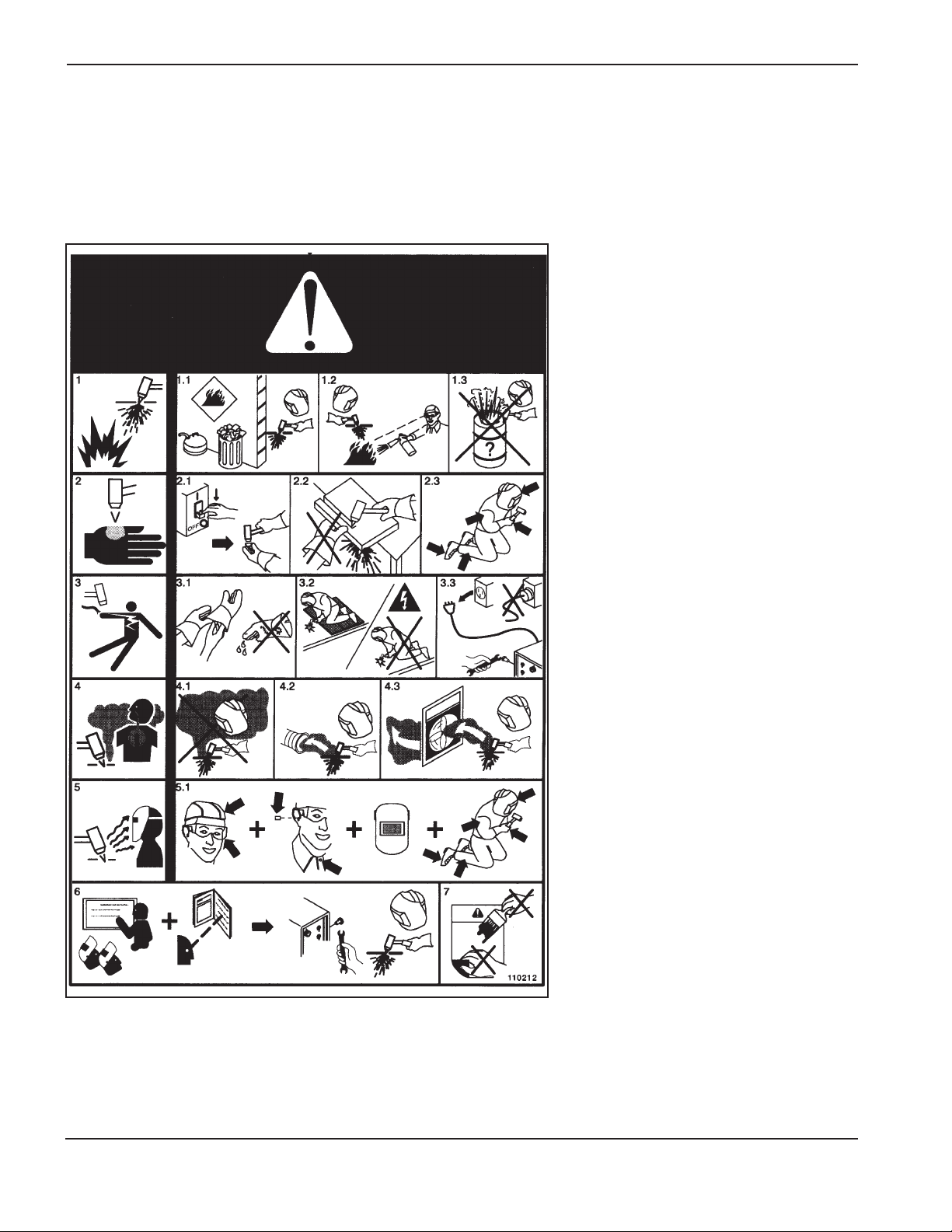
SÉCURITÉ
1a-6 Hypertherm Systèmes plasma
2/12/01
Étiquette de sécurité
Cette étiquette est affichée sur la source de courant. Il est important
que l’utilisateur et le technicien de maintenance comprennent la
signification des symboles de sécurité. Les numéros de la liste
correspondent aux numéros des images.
1. Les étincelles produites par le coupage
peuvent provoquer une explosion ou un
incendie.
1.1 Pendant le coupage, éloigner toute matière
inflammable.
1.2 Conserver un extincteur à proximité et
s’assurer qu’une personne soit prête à
l’utiliser.
1.3 Ne jamais couper de récipients fermés.
2. L’arc plasma peut provoquer des blessures
et des brûlures.
2.1 Couper l’alimentation avant de démonter la
torche.
2.2 Ne pas tenir la surface à couper près de la
trajectoire de coupe.
2.3 Porter des vêtements de protection
couvrant tout le corps.
3. Un choc électrique causé par la torche ou
les câbles peut être fatal. Se protéger
contre les risques de chocs électriques.
3.1 Porter des gants isolants. Ne pas porter de
gants mouillés ou abîmés.
3.2 S’isoler de la surface de travail et du sol.
3.3 Débrancher la prise ou la source de
courant avant de manipuler l’équipement.
4. L’inhalation des vapeurs produites par le
coupage peut être dangereuse pour la
santé.
4.1 Garder le visage à l’écart des vapeurs.
4.2 Utiliser un système de ventilation par
aspiration ou d’échappement localisé pour
dissiper les vapeurs.
4.3 Utiliser un ventilateur pour dissiper les
vapeurs.
5. Les rayons de l’arc peuvent brûler les yeux
et provoquer des lésions de la peau.
5.1 Porter un casque et des lunettes de
sécurité. Se protéger les oreilles et porter
une chemise dont le col peut être
déboutonné. Porter un casque de soudure
dont la protection filtrante est suffisante.
Porter des vêtements protecteurs couvrant
la totalité du corps.
6. Se former à la technique du coupage et lire
les instructions avant de manipuler
l’équipement ou de procéder au coupage.
7. Ne pas retirer ou peindre (recouvrir) les
étiquettes de sécurité.
Page 26

HT4400 Instruction Manual 2-1
7
Section 2
SPECIFICATIONS
In this section:
System Components.......................................................................................................................................2-2
Power Supply ........................................................................................................................................2-2
Machine Torch ........................................................................................................................................2-2
Valve Cluster ..........................................................................................................................................2-2
Gas Console...........................................................................................................................................2-2
Ignition Console......................................................................................................................................2-2
Cooler.....................................................................................................................................................2-2
Remote Current Control Console - Optional...........................................................................................2-2
Command THC - Optional......................................................................................................................2-2
Specifications..................................................................................................................................................2-3
System Requirements ............................................................................................................................2-3
Power Supply .........................................................................................................................................2-4
Machine Torch .......................................................................................................................................2-5
Valve Cluster ..........................................................................................................................................2-5
Gas Console...........................................................................................................................................2-6
Ignition Console......................................................................................................................................2-7
Cooler.....................................................................................................................................................2-8
Remote Current Control Console - Optional...........................................................................................2-9
Command THC - Optional......................................................................................................................2-9
Page 27

SPECIFICATIONS
2-2 HT4400 Instruction Manual
7
System Components
See Section 3 for details of the system interconnections.
Power Supply
The power supply houses four 100-amp, 15 kHz choppers to produce up to 400A of constant current DC output.
Machine Torch
The maximum production cutting capability of the torch is 1-1/4 inches (32 mm). To achieve consumable long
life, all cuts must begin and end on the plate surface.
Valve Cluster
The valve cluster consists of 5 valves and interfaces with the machine torch, the ignition console and the gas
console. The valve cluster must be located within 4 ft (1.2 m) of the torch and within 50 ft (15.3 m) of the gas
console.
Gas Console
This unit houses metering and solenoid valves, pressure readout LEDs and gas selection switches to choose, set
and monitor plasma and shield gases. The gas console must be located within 50 ft (15.3 m) of the valve cluster.
Ignition Console
The ignition console generates a high voltage, high frequency signal and couples it to the cathode lead and pilot
arc lead. This ignition console must be located within 15 feet (4.6 m) of the torch.
Cooler
This unit circulates a coolant solution to the torch. The cooler interfaces with the ignition console and the power
supply. For more information, see Torch Coolant Requirements in the Installation section of this manual.
Remote Current Control Console - Optional
The remote current control console contains a thumb-wheel switch to set the arc current. If a machine interface will
provide current control for the plasma system, you will not need this console.
Command THC - Optional
The Command THC is an external torch height control and initial height sensing system designed for plasma
cutting applications on an x-y cutting table. Refer to the Command THC instruction manual 802780 for more
detailed information.
Page 28
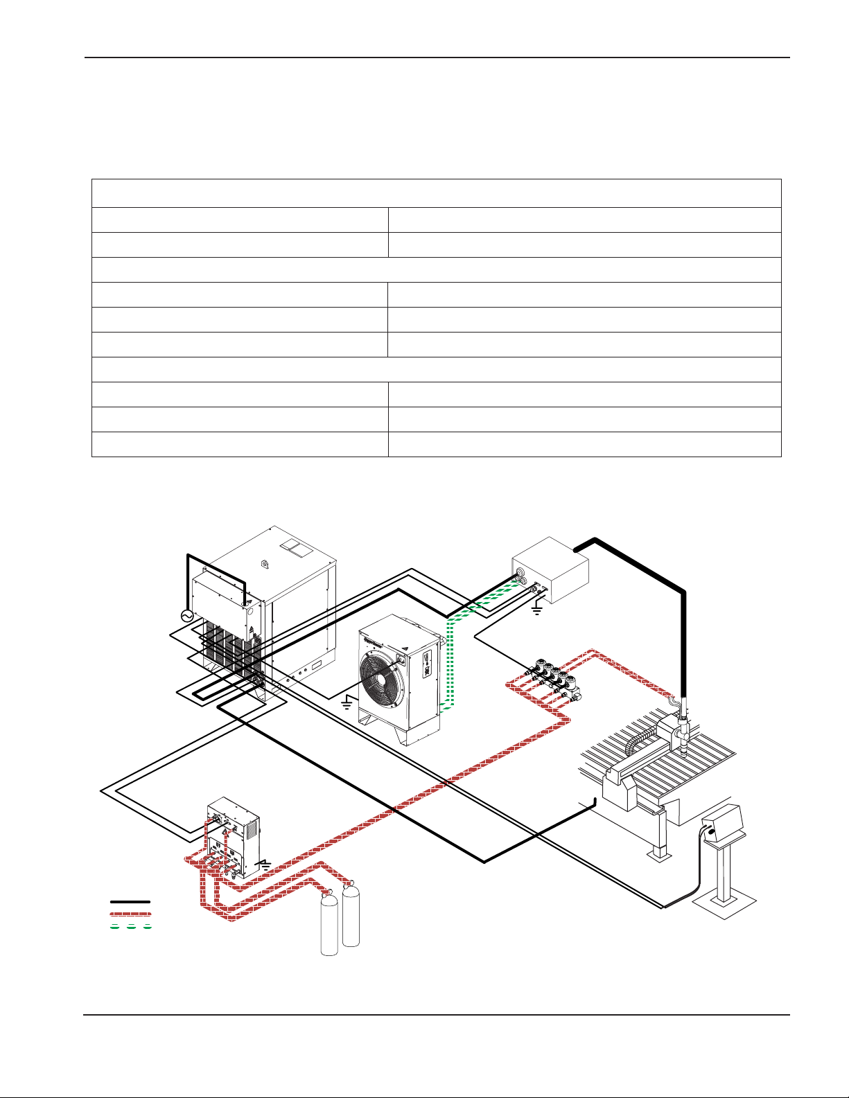
SPECIFICATIONS
HT4400 Instruction Manual 2-3
6
Cables
Gas Hoses
Coolant Hoses
System components not drSystem components not drawn to scale
Specifications
System Requirements
Gas Requirements:
Plasma Gas Types Oxygen, Nitrogen
Shield Gas Types Air; Nitrogen
Gas Quality:
Oxygen 99.5% pure (liquid gas recommended)
Nitrogen 99.995% pure (liquid gas recommended)
Air 99.995% pure (liquid gas recommended)
Maximum Gas Flow Rates and Inlet Pressures:
Oxygen 140 scfh (3965 sclh) @ 120 psi +/- 10 psi (8.3 bar +/- 0.7 bar)
Nitrogen 250 scfh (7080 sclh) @ 120 psi +/- 10 psi (8.3 bar +/- 0.7 bar)
Air 200 scfh (5664 sclh) @ 120 psi +/- 10 psi (8.3 bar +/- 0.7 bar)
Page 29
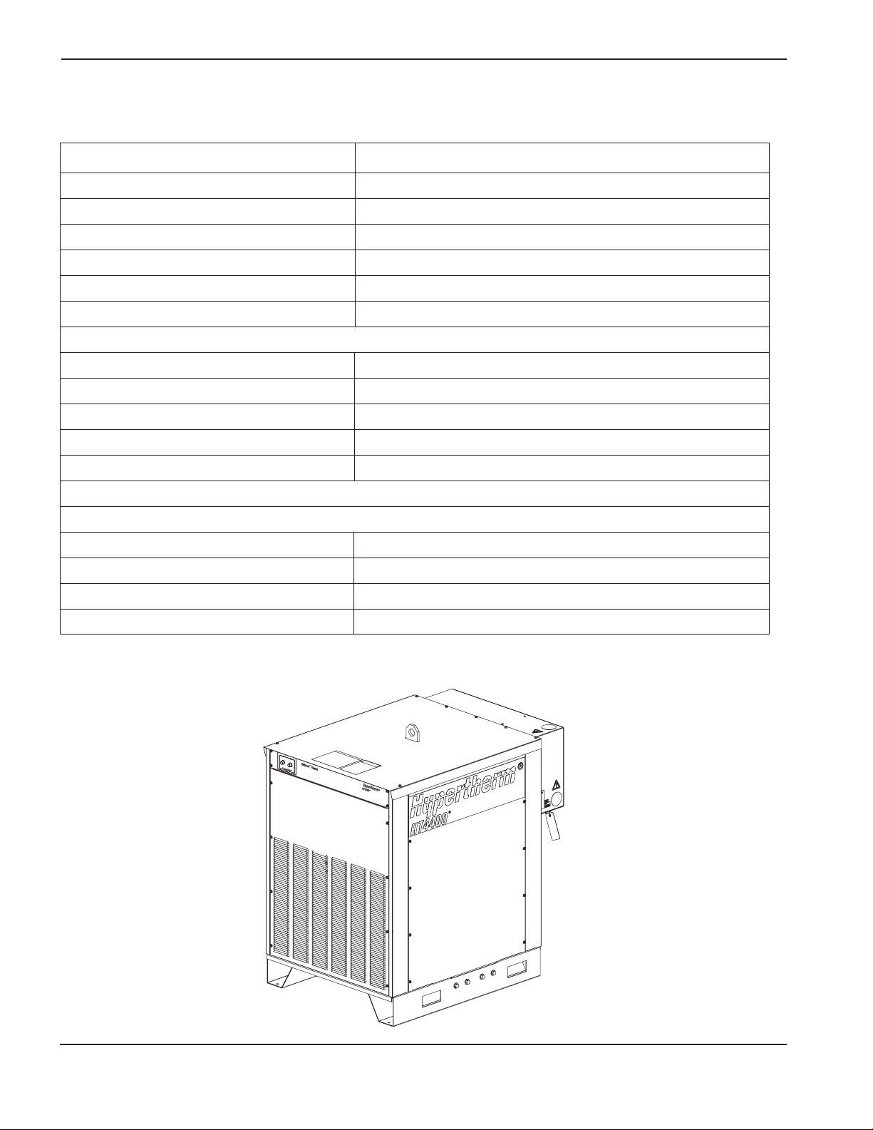
Maximum OCV (U0) 361 VDC
Maximum Output Current (I2) 400 Amps
Output Voltage (U2) 80-200 VDC
Duty Cycle Rating (X) 100% @ 89 kVa, 104° F (40° C)
Temperature Rating 14° F (-10° C) to 104° F (40° C)
Power Factor (cosϕ) 0.94
Cooling Forced Air (Class F)
Input Power (Input Voltage [U1– Input Voltage; I1– Input Current])
077036 200 VAC (U1), 3 Phase, 50-60 Hz, 257A (I1)
077037 400 VAC (U1), 3 Phase, 50-60 Hz, 128A (I1)
077046 440 VAC (U1), 3 Phase, 50-60 Hz, 117A (I1)
077033 480 VAC (U1), 3 Phase, 60 Hz, 107A (I1)
077038 600 VAC (U1), 3 Phase, 60 Hz, 86A (I1)
*
In accordance with IEC 61000-3-12, the R
sce
(short Circuit Ratio) for the 400 VAC power supply is 100.
Dimensions and Weight
Width 34" (863 mm)
Maximum Height 51" (1295 mm)
Maximum Depth 48-11/16" (1236 mm)
Weight 1800 lbs (817 kg)
SPECIFICATIONS
2-4 HT4400 Instruction Manual
3
Power Supply
Page 30
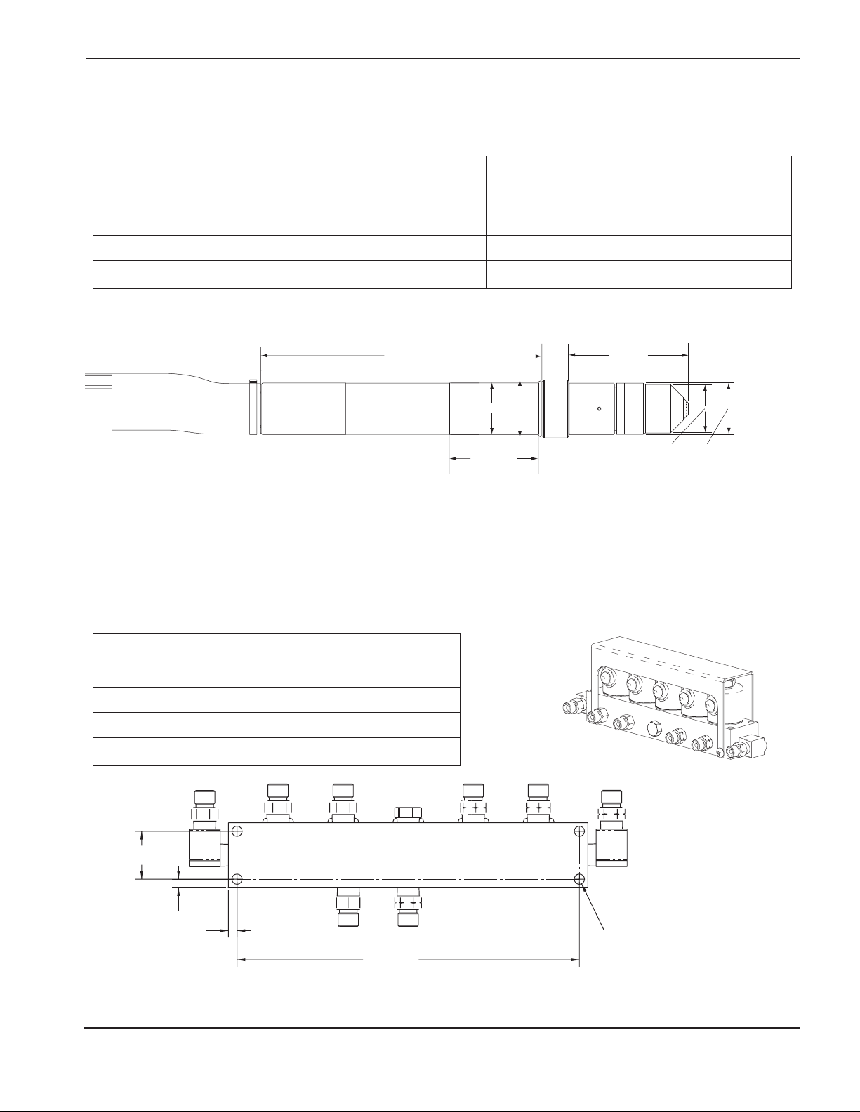
SPECIFICATIONS
HT4400 Instruction Manual 2-5
Machine Torch – 128342 (with 15 ft (4.6 m) Leads)
See Section 6 Parts List for other lead lengths
Maximum recommended production cutting thickness 1-1/4" (32 mm)
Maximum current at 100% duty cycle 400 Amp
Dimensions See figure below
Weight - Torch only 2 lbs (0,9 kg)
Weight - Torch and 15 ft (4.6 m) leads w/o coolant 14.7 lbs (6,7 kg)
Dimensions and Weight
Weight 6.6" (168 mm)
Height 2.5" (64 mm)
Depth 1.2" (30 mm)
Weight 2.5 lbs (1,1 kg)
Torch with Dimensions
Valve Cluster Mounting Dimensions
0.88"
(22 mm)
0.16"
(4 mm)
0.16"
(4 mm)
6.25"
(159 mm)
0.19" (4.8 mm)
diameter.
Valve Cluster – 077035
3.1
2.25"
1.05"
(27
mm)
10.86"
(276 mm)
2"
(51 mm)
(89 mm)
(57 mm)
3.5"
4.65"
(118 mm)
1.88"
(48 mm)
1.98"
(50 mm)
Page 31

SPECIFICATIONS
2-6 HT4400 Instruction Manual
Dimensions and Weight
Width 11.5" (290 mm)
Height 14.5" (370 mm)
Depth 5.0" (127 mm)
Weight 28.7 lbs (13 kg)
Gas Console – 077032
Gas Console Mounting Dimensions (bottom view)
5.0"
(127 mm)
4.0"
(102 mm)
1.0"
(25 mm)
0
0
2.0"
(51 mm)
PEM #S-0420-1
(6 places)
5.75"
(146 mm)
9.5"
(241 mm)
2
Page 32

SPECIFICATIONS
HT4400 Instruction Manual 2-7
7
0
0
Dimensions and Weight
Width 12" (305 mm)
Height 6.25" (159 mm)
Depth 11.25" (286 mm)
Weight 20.5 lbs (9.3 kg)
Ignition Console – 078088
Ignition Console Mounting Dimensions (bottom view)
Vertical MountingHorizontal Mounting
1.25" (32 mm) 10.63" (270 mm)
11.0"
(279 mm)
9.75" (248 mm)
1.25" (32 mm)
0.28" (7 mm)
diameter.
(4 places)
Hypertherm recommends mounting the ignition console either horizontally or in the vertical position with the
power supply and cooler connections facing out as shown.
Power supply and
cooler connections
Page 33

SPECIFICATIONS
2-8 HT4400 Instruction Manual
7.1
Dimensions and Weight
Width 23" (584 mm)
Height 36" (914 mm)
Depth 15.8" (401 mm)
Weight 148 lbs (67,2 kg)
Coolant capacity 2.5 gal (9.5 l)
Maximum coolant flow 0.85 gpm (3.2 l/min)
Cooler– 077034
23"
(584 mm)
36"
(914 mm)
Cooler with Dimensions
15.8"
(401 mm)
Page 34

SPECIFICATIONS
HT4400 Instruction Manual 2-9
3-00
Dimensions and Weight
Width 6.5" (165 mm)
Height 2.5" (64 mm)
Depth 8.63" (219 mm)
Weight 3 lbs (1 kg)
Remote Current Control Console – Optional – 077020
5/32" ø (4 mm) - 4 places
3.38" (86 mm)
6.25" (159 mm)
8.5" (216 mm)
0.50" (13 mm)
1.17"
(30 mm)
Command THC - Optional
Refer to the Command THC Instruction Manual 802780.
Remote Current Control Mounting Dimensions (bottom view)
6.50"
(165 mm)
Page 35

HT4400 Instruction Manual 3-1
7.1
Section 3
INSTALLATION
In this section:
Installation Requirements................................................................................................................................3-2
Gas Requirements ..........................................................................................................................................3-2
Gas Supply Plumbing......................................................................................................................................3-2
Torch Coolant Requirements for Coolant Mixture ...........................................................................................3-3
Water Purity Requirements.............................................................................................................................3-4
Grounding Requirements................................................................................................................................3-4
Fume Emissions..............................................................................................................................................3-4
Noise Levels....................................................................................................................................................3-5
Power Requirements.......................................................................................................................................3-5
Connecting the Power.....................................................................................................................................3-6
Torch Lifter Requirement.................................................................................................................................3-8
System Units Placement.................................................................................................................................3-8
HT4400 System Interconnections ................................................................................................................3-11
Ignition Console Connections - 1 of 3 ...........................................................................................................3-12
Ignition Console Connections - 2 of 3 ...........................................................................................................3-13
Ignition Console Connections - 3 of 3 ...........................................................................................................3-14
Gas Console Connections - 1 of 3 ................................................................................................................3-15
Gas Console Connections - 2 of 3 ................................................................................................................3-16
Gas Console Connections - 3 of 3 ................................................................................................................3-17
Cooler Connections - 1 of 2 ..........................................................................................................................3-18
Cooler Connections - 2 of 2 ..........................................................................................................................3-19
Remote Current Control Connection.............................................................................................................3-20
Machine Interface Connections - 1 of 2 ........................................................................................................3-20
Machine Interface Connections - 2 of 2 ........................................................................................................3-21
Work Table Connection .................................................................................................................................3-22
Power Supply #2 Connection........................................................................................................................3-22
Torch Connections ........................................................................................................................................3-23
Torch Mounting and Alignment......................................................................................................................3-24
Post-Installation.............................................................................................................................................3-25
Page 36

INSTALLATION
3-2 HT4400 Instruction Manual
4-00
Installation Requirements
All installation and service of the electrical and plumbing systems must conform to national or local codes.
This work should be performed only by qualified, licensed personnel.
Direct any technical questions to the nearest Hypertherm Technical Service Department listed in the front of this
manual, or your nearest authorized Hypertherm distributor.
Gas Requirements
The customer furnishes all gases and gas-supply regulators for the system. Use a high-quality, 2-stage pressure
regulator located within 10 ft (3 m) of the gas console. See Appendix C for gas regulator recommendations. Refer
to Section 2 for gas and flow specifications.
Caution: Gas supply pressures not within the parameters outlined in Section 2 can cause poor cut
quality, poor consumable life, and operational problems.
If the purity level of the gas is too low or if there are leaks or contamination in the supply
hoses or connections,
• Cut speeds can decrease
• Cut quality can deteriorate
• Cutting thickness capability can decrease
• Parts life can shorten
Gas Supply Plumbing
Rigid copper plumbing or suitable flexible hose may be used for all gas supplies. Do not use steel pipe. After installation, pressurize the entire system and check for leaks.
For flexible-hose systems, use a hose designed for inert gas to carry air or nitrogen.
CAUTION: Only hose designed to carry oxygen may be used for oxygen lines.
Note: When cutting with oxygen as the plasma gas, nitrogen must also be connected to the gas console to
achieve the proper oxygen/nitrogen mixtures in the preflow and cutflow conditions.
WARNING
CUTTING WITH OXYGEN CAN CAUSE FIRE OR EXPLOSION
Cutting with oxygen as the plasma gas can cause a potential fire hazard due to the oxygen-enriched
atmosphere that it creates. As a precaution, Hypertherm recommends that an exhaust ventilation
system be installed when cutting with oxygen.
Page 37

Caution: Always use propylene glycol in the coolant mixture. Do not use automotive antifreeze in
place of propylene glycol. Antifreeze contains corrosion inhibitors that will damage the
torch coolant system.
Caution: Always use purified water in the coolant mixture in order to prevent corrosion in the torch
coolant system. See Water Purity Requirements for Coolant Mixture.
INSTALLATION
HT4400 Instruction Manual 3-3
8
Torch Coolant Requirements
The cooler is shipped to the customer without any coolant in the tank. Hypertherm recommends a mixture of 30%
propylene glycol, 69.9% deionized water, and .1% benzotriazole. This mixture resists freezing to +10° F (-12° C)
and contains a corrosion inhibitor (benzotriazole) to protect copper surfaces in the coolant loop. This mixture is
available in one-gallon containers by ordering 028872. 100% propylene glycol is available by ordering 028873.
Caution: For operating temperatures colder than the temperature stated above, the percentage of
propylene glycol must be increased. Failure to do so could result in a cracked torch head,
hoses, or other damage to the torch coolant system due to the torch coolant freezing.
See Figure b-1 chart in Appendix B to determine if a stronger propylene glycol/purified water solution is needed for
your particular application.
Observe the warning and cautions below. Refer to the Material Safety Data Sheets in Appendix B for data on
safety, handling, and storage of propylene glycol and benzotriazole.
WARNING
COOLANT CAN BE IRRITATING TO SKIN AND EYES AND
HARMFUL OR FATAL IF SWALLOWED
Propylene glycol and benzotriazole are irritating to skin and eyes, and harmful or fatal if swallowed.
Upon contact, flush skin or eyes with water. If swallowed, drink water and call a physician
immediately. Do not induce vomiting.
Caution
Use Hypertherm coolant (028872) to reduce the risk of damage from
freezing and to prevent long-term corrosion.
Page 38

INSTALLATION
3-4 HT4400 Instruction Manual
7
Water Purity Requirements for Coolant Mixture
Maintaining a low level of calcium carbonate is critical for proper performance of the torch and components in the
cooling system. Water purity should meet the requirements defined in the table below. When mixing Hypertherm
coolant (P/N 028873 - 100% propylene glycol) with water to create the appropriate coolant mixture.
Note: If water purity exceeds maximum levels, mineral deposits may occur throughout the system.
If water purity is below minimum levels, soluble materials may leach into the coolant.
Water Purity Measurement Methods
Conductivity Resistivity Dissolved Grains per
Water Purity µS/cm M /cm Solids Gallon
at 77° F (25° C) at 77° F (25° C) (ppm of NaCl) (gpg of CaCO2)
Pure Water (ref. only) 0.055 18.3 0 0
Maximum Purity 0.5 2 0.206 0.010
Minimum Purity 18 0.054 8.5 0.43
Max. Potable Water
(ref. only) 1000 0.001 495 25
Grounding Requirements
Proper grounding is essential for personal safety and to prevent emission of high-frequency interference.
See Appendix A for system grounding requirements.
Connect the worktable to a high-quality earth ground, not more than 20 feet (6 m) from the table. A suitable ground
consists of a solid copper rod of at least 3/4" (19 mm) diameter driven to a depth of at least 15 feet
(4.5 m) into the earth, below the permanent moisture level. Ensure that all grounding connections are tight to avoid
excessive heating. See also Grounding in the Safety section. For additional information, consult
national or local electric codes.
Caution: All accessory modules in the HT4400 system must be grounded to earth. Use a minimum of
8 AWG (10 mm2) wire connected from the stud on the side of each module enclosure to the
worktable ground.
Note: The customer must supply all grounding wire.
Fume Emissions
Contact Hypertherm to receive the publication, Fume Emissions Testing for Plasma Arc Cutting.
Page 39

Rated Input Recommended Recommended
Input Current @ 89 kW Recommended Cable Size (AWG) rated Cable Size (AWG) rated
Voltage Phase Output Slow-Burn Fuse Size for 60° C (140° F) for 90° C (194° F)
200 VAC 3 257 amps 350 amps *See Note below 4/0 AWG
400 VAC 3 128 amps 175 amps 2/0 AWG 2 AWG
440 VAC 3 117 amps 175 amps 2/0 AWG 2 AWG
480 VAC 3 107 amps 150 amps 1 AWG 3 AWG
600 VAC 3 86 amps 125 amps 2 AWG 4 AWG
INSTALLATION
HT4400 Instruction Manual 3-5
2.1
Noise Levels
Acceptable noise levels as defined by national or local codes may be exceeded by this plasma system. Always
wear proper ear protection when cutting with the plasma system. See also Noise Protection in the Safety section of
this manual. See also Appendix D for noise levels measured on the HT4400 system.
Power Requirements
All switches, slow-blow fuses and power cables are customer supplied and must be chosen as outlined by
applicable national or local codes. Installation must be performed by qualified personnel. Use a separate
primary line disconnect switch for the power supply. If slow-blow fuses are not available or not allowed by
applicable codes, use a motor-start circuit breaker.
* Note: Use the smaller diameter 4/0 AWG cable (1.6" / 40.6 mm) rated for 90° C (194° F) rather than an equivalent
larger diameter cable (350 MCM, 2.05" / 52 mm) rated for 60° C (140° F) to accommodate the bend radius necessary to connect incoming power cable to the power supply.
Line Disconnect Switch
The line disconnect switch serves as the supply voltage disconnecting (isolating) device. Install this switch on a
wall near the power supply for easy accessibility by the operator. The line disconnect switch must be installed
by qualified personnel following all applicable national or local codes. The switch should:
• isolate the electrical equipment and disconnect all live conductors from the supply voltage when in the "OFF
position
• have one "OFF" and one "ON" position clearly marked with "0" (OFF) and "1" (ON)
• have an external operating handle capable of being locked in the "OFF" position
• contain a power operated mechanism that serves as an emergency stop
• have slow-blow fuses installed for the proper breaking capacity (see table above)
Power Cable
Wire sizes vary based on the distance of the receptacle from the main box. The suggested wire sizes listed in the
table above were taken from the U.S. National Electric Code 1990 handbook, table 310.16. Use a 4-conductor (3
conductor with ground) input power cable with a conductor temperature rating of 60° C (140° F) or 90° C (194° F).
The cable should be installed only by a licensed electrician following national or local codes.
Page 40

INSTALLATION
3-6 HT4400 Instruction Manual
7
Positioning the Power Supply
WARNING
ELECTRICAL SHOCK CAN KILL
Remove all electrical connections to power supply before moving or positioning. Transporting
unit can cause personal injury and equipment damage.
WARNING
ELECTRICAL SHOCK CAN KILL
The line disconnect switch must be in the OFF position before making the power cable connections!
In the U.S., use a "lock-out/tag-out" procedure until installation is complete. In other countries, follow
appropriate local or national safety procedures.
Note: A lifting eye is provided for moving the power supply into place with a crane or hoist. It may also be moved
by forklift if the forks are long enough to extend the entire length of the base. Take care when lifting with the
forks so that the underside of the power supply is not damaged.
• Place the power supply in an area that is free of excessive moisture, has proper ventilation, and is relatively
clean. Provide at least 3 feet (1 m) of room on all sides of the power supply to allow for easy access when
servicing, and to allow the cooling fans to function properly.
• Cooling air is drawn in through the front panel grating, and exhausted through the rear of the unit by a
cooling fan. Do not place any filter device over the air intake locations. This reduces cooling efficiency and
VOIDS THE WARRANTY.
Positioning the Cooler
• Place the cooler in an area that is free of excessive moisture, has proper ventilation, and is relatively clean.
Provide at least 3 feet (1 m) of room on all sides of the cooler to allow for easy access when servicing, and
to allow the cooling fans to function properly.
Connecting the Power
Page 41

INSTALLATION
HT4400 Instruction Manual 3-7
6
Connecting the Power - All Voltages
1. Be certain that the line disconnect switch is in the OFF position and remains in the OFF
position for the remainder of the installation of the HT4400 system.
2. Insert the power cable through the strain relief located in the rear of the power supply.
3. Connect the power leads to the W, V, and U terminals of TB5. See figure below.
4. Connect the ground lead (PE) to the stud marked as shown below.
5. Connect the power cord leads to the line disconnect switch following national or local electrical codes..
Strain Relief
Note: Filter on
400 VAC CE
power supplies only
WARNING
ELECTRICAL SHOCK CAN KILL
There is line voltage at the contactor if the line disconnect switch is in the ON position, even if the
circuit breaker on the power supply is OFF. As a common safety practice, ALWAYS verify that the
line disconnect switch is in the OFF position before installing, disconnecting or servicing in this
area.
W
V
U
TB5
Page 42

INSTALLATION
3-8 HT4400 Instruction Manual
8
Torch Lifter Requirement
The HT4400 system requires a high-quality, motorized torch lifter with sufficient travel to cover all cutting thickness
requirements. The lifter must provide 10 inches (254 mm) of vertical travel. The unit should have a constant
speed of at least 20 ipm (508 mm/min) with positive braking. A unit which drifts through the stop point is not acceptable.
Use 2 wrenches when tightening to prevent damage to the mating component.
• Install the cooler, the ignition console and connecting coolant hoses at a lower height than the torch to
prevent leaking when the torch body is disconnected from the torch leads.
Use the HT4400 System Connections diagram later in this section to help make the system cable, torch and hose
connections. Follow the number guide on the diagram to find out specific information on each cable, hose or connection. The numbered items are detailed on the pages following the diagram.
System Units Placement
• Position all required units prior to making electrical, gas and interface connections.
• Ground all external modules in the HT4400 system to earth.
• To prevent leaks in the system, tighten all gas and coolant connections to the following specifications:
Gas or Coolant
Torque Specification
Hose Size
lbf-in lbf-ft kgf-cm
Up to 3/8" (9.5 mm) 75-85 6.25-7 86-98
1/2" (12 mm) 360-480 30-40 415-550
Caution
Use Hypertherm coolant (028872) to reduce the risk of damage from
freezing and to prevent long-term corrosion.
Page 43

INSTALLATION
HT4400 Instruction Manual 3-9
Notes
Page 44

3-10 HT4400 Instruction Manual
7
(Logic +
12VDC,
close to
start)
Power Supply
Center Bail Front
Power Supply
Rear Wall Inside
Power Supply Rear Panel
Power Supply
Center Bail Rear
13a
1
2
3
6
7
11
13b
14
15
16
Page 45

HT4400 Instruction Manual 3-11
7
Ignition Console connections - pgs. 3-12, -13, -14
Gas Console connections - pg. 3-15, -16, -17
Cooler connections - pg. 3-18, -19
Remote Current Control connections - pg. 3-20
Machine Interface connections - pgs. 3-20, -21
Work Table connection - pg. 3-22
Power supply #2 connection – pg. 3-22
Valve Cluster
Command THC connection - see instruction manual 802780
Torch Connections,
Mounting and
Alignment
- pg. 3-23
HT4400 System Interconnections
13a
1
2
3
6
7
9
10
4
8
5
5
12
11
13b
O
2
N
2
10a
Air
14
15
16
Page 46

INSTALLATION
3-12 HT4400 Instruction Manual
Ignition Console Connections – 1 of 3
See Cooler
Connections - pg. 3-18, 3-19
See also Torch Connections, Mounting and
Alignment later in this section.
See Cooler Connections - pg. 3-18, 3-19
2X1 2X2
Out
Green
Red
In
Green
Red
7
Page 47

INSTALLATION
HT4400 Instruction Manual 3-13
Ignition Console Connections – 2 of 3
Nozzle (Pilot Arc) Lead (+)
Negative Lead (-)
Cable - Ignition Console to Power Supply
Installation Notes
Attach the ring terminal end of the nozzle
lead to the bolt in the center panel of the
ignition console as shown in the lower left
figure on page 3-12. Secure the attached
strain relief to the panel of the ignition
console by tightening the nut in place.
Pass the fork terminal end of the nozzle
lead through the small bushing in the
lower rear of the power supply and
connect to the start circuit assembly as
shown on page 3-10.
Pass the negative lead through one of
the 2" bushings in the lower rear of the
power supply and connect to the lower
bar (-) on the center bail rear as shown
on page 3-10.
RUN LIST – Ignition Console to
Power Supply Cable
Note: 2X1 and 1X1 are not labeled on the
cable. Plug one cable end into the 2X1 Ignition
Console receptacle and the other cable end
into the 1X1 Power Supply receptacle.
SIGNAL 2X1 COLOR 1X1
S.S.I. 1 Black 1
S.S.I. 14 Red 14
SV8 7 Black 7
SV8 20 Orange 20
SV9 8 Red 8
SV9 21 White 21
SV10 9 Red 9
SV10 22 Green 22
SV11 10 Red 10
SV11 23 Blue 23
SV12 11 Red 11
SV12 24 Yellow 24
Gnd 6 Black 6
Gnd 12 Red 12
Gnd 19 Brown 19
Gnd 25 Brown 25
Part No. Length
123552 10 ft (3 m)
123553 15 ft (4.6 m)
123554 20 ft (6.1 m)
123528 25 ft (7.6 m)
123555 30 ft (9.2 m)
123556 40 ft (12.2 m)
123529 50 ft (15.3 m)
Part No. Length
123530 60 ft (18.3 m)
123531 75 ft (22.9 m)
123532 100 ft (30.5 m)
123534 125 ft (38.1 m)
123535 150 ft (45.8 m)
123536 175 ft (53.4 m)
123537 200 ft (61 m)
Part No. Length
123418 10 ft (3 m)
023382 15 ft (4.6 m)
023136 20 ft (6.1 m)
023078 25 ft (7.6 m)
023101 30 ft (9.2 m)
023135 40 ft (12.2 m)
023079 50 ft (15.3 m)
Part No. Length
123316 60 ft (18.3 m)
023124 75 ft (22.9 m)
023080 100 ft (30.5 m)
123084 125 ft (38.1 m)
023081 150 ft (45.8 m)
123097 175 ft (53.4 m)
023188 200 ft (61 m)
Part No. Length
123446 10 ft (3 m)
123557 15 ft (4.6 m)
123447 20 ft (6.1 m)
123448 25 ft (7.6 m)
123449 30 ft (9.2 m)
123450 40 ft (12.2 m)
123512 50 ft (15.3 m)
Part No. Length
123559 60 ft (18.3 m)
123513 75 ft (22.9 m)
123514 100 ft (30.5 m)
123515 125 ft (38.1 m)
123516 150 ft (45.8 m)
123560 175 ft (53.4 m)
123561 200 ft (61 m)
2X1 1X1
Page 48

INSTALLATION
3-14 HT4400 Instruction Manual
Ignition Console Connections – 3 of 3
Cable - Ignition Console to Valve Cluster
Torch Leads
Installation Notes
RUN LIST – Ignition Console to
Valve Cluster Cable
Note: 2X2 and 4X1 are not labeled on the
cable. Plug one cable end into the 2X2 Ignition
Console receptacle and the other cable end
into the Valve Cluster cable receptacle.
SIGNAL 2X2 COLOR 4X1
SV8 7 White 1
SV8 20 Yellow 2
SV9 8 White 4
SV9 21 Orange 5
SV10 9 White 7
SV10 22 Brown 8
SV11 10 White 10
SV11 23 Black 11
SV12 11 White 13
SV12 24 Red 14
PE (Gnd) 6 White 12
PE (Gnd) 12 Green 3
See also Torch Connections, Mounting
and Alignment later in this section.
Part No. Length
123509 6 ft (1.8 m)
123510 10 ft (3 m)
Part No. Length
123511 15 ft (4.6 m)
Part No. Length
128462 6 ft (1.8 m)
128463 10 ft (3 m)
128341 15 ft (4.6 m)
2X2 4X1
2
Page 49

INSTALLATION
HT4400 Instruction Manual 3-15
2
Gas Console Connections – 1 of 3
Cable 1 - Gas Console to Power Supply
Installation Notes
RUN LIST – Gas Console to
Power Supply Cable -1
Note: 3X2 and 1X3 are not labeled on the
cable. Plug one cable end into the 3X2 Gas
Console receptacle and the other cable end
into the 1X3 Power Supply receptacle.
SIGNAL 3X2 COLOR 1X3
28V 1 Black 1
Gnd 14 Red 14
28V Return 3 Black 3
Gnd 16 Blue 16
PS1 5 Black 5
Gnd 18 Brown 18
PS2 6 Black 6
Gnd 19 Orange 19
SOD+ 8 Red 8
Gnd 21 Green 21
SOD– 9Red 9
Gnd 22 Blue 21
Str2+ 10 Red 10
Gnd 23 Yellow 23
Str2– 11 R ed 11
Gnd 24 Brown 24
Clk2+ 12 Red 12
Gnd 25 Orange 25
Clk2– 7Red 7
Gnd 20 White 20
Part No. Length
123446 10 ft (3 m)
123557 15 ft (4.6 m)
123447 20 ft (6.1 m)
123448 25 ft (7.6 m)
123449 30 ft (9.2 m)
123450 40 ft (12.2 m)
123512 50 ft (15.3 m)
Part No. Length
123559 60 ft (18.3 m)
123513 75 ft (22.9 m)
123514 100 ft (30.5 m)
123515 125 ft (38.1 m)
123516 150 ft (45.8 m)
123560 175 ft (53.4 m)
123561 200 ft (61 m)
3X2
1X3
3X1
Green Green
Green
Red
Red
Green
Red Red
N2In
O
2
InAir In
3X2
10a
Page 50

INSTALLATION
3-16 HT4400 Instruction Manual
Gas Console Connections – 2 of 3
Cable 2 - Gas Console to Power Supply
Hoses - Gas Console to Valve Cluster
Installation Notes
RUN LIST – Gas Console to
Power Supply Cable -2
SIGNAL 3X1 COLOR 1X2
Select O2/N2 1 Shield 1
Select O2/N2 5 Black 5
Select O2/N2 6 White 6
SV1 2 Black 2
SV1 3 Green 3
Gnd 7 Shield 7
SV2 8 Black 8
SV2 9 Blue 9
Gnd 4 Shield 4
BCD Common 10 Shield 10
BCD Bit 8 16 Black 16
BCD Bit 4 17 Yellow 17
BCD Bit 2 11 Black 11
BCD Bit 1 12 Brown 12
Gnd 18 Shield 18
SV6 19 Black 19
SV6 20 Orange 20
Gnd 13 Shield 13
SV3 23 Red 23
SV3 24 Yellow 24
Gnd 25 Shield 25
SV5 26 Red 26
SV5 27 Brown 27
Gnd 28 Shield 28
SV7 29 Black 29
SV7 30 Red 30
Gnd 34 Shield 34
SV Purge 32 Red 32
SV Purge 33 Blue 33
Gnd 37 Shield 37
SV4 35 Red 35
SV4 36 Green 36
Gnd 31 Shield 31
Part No. Length
123562 10 ft (3 m)
123563 15 ft (4.6 m)
123564 20 ft (6.1 m)
123565 25 ft (7.6 m)
123566 30 ft (9.2 m)
123567 40 ft (12.2 m)
023496 50 ft (15.3 m)
Part No. Length
123568 60 ft (18.3 m)
023497 75 ft (22.9 m)
023498 100 ft (30.5 m)
123087 125 ft (38.1 m)
023499 150 ft (45.8 m)
123031 175 ft (53.4 m)
023500 200 ft (61 m)
3X1
1X2
Hose Package – Plasma Plasma- Shield- Shield
Gas Console to Length Preflow Cutflow Preflow Cutflow Plasma Shield
Valve Cluster: (green tape) (red tape) (green tape) (red tape) Sense Sense
128482 5 ft (1.5 m) 024620 024620 024628 024628 024591 024599
128483 10 ft (3 m) 024621 024621 024629 024629 024590 024598
128484 15 ft (4.6 m) 024622 024622 024630 024630 024589 024597
128485 20 ft (6.1 m) 024623 024623 024631 024631 024588 024596
128486 25 ft (7.6 m) 024624 024624 024632 024632 024587 024595
128487 30 ft (9.2 m) 024625 024625 024633 024633 024586 024594
128488 40 ft (12.2 m) 024626 024626 024634 024634 024585 024593
128489 50 ft (15.3 m) 024627 024627 024635 024635 024584 024592
128518 60 ft (18.3 m) 024653 024653 024652 024652 024650 024651
4-00
Page 51

INSTALLATION
HT4400 Instruction Manual 3-17
2
Gas Console Connections – 3 of 3
Oxygen Hose - Gas Console to Gas Supply
Nitrogen Hose - Gas Console to Gas Supply
Part No. Length
024607 10 ft (3 m)
024204 15 ft (4.6 m)
024608 20 ft (6.1 m)
024205 25 ft (7.6 m)
024609 30 ft (9.2 m)
024610 40 ft (12.2 m)
024155 50 ft (15.3 m)
Part No. Length
024611 60 ft (18.3 m)
024398 75 ft (22.9 m)
024206 100 ft (30.5 m)
024490 125 ft (38.1 m)
024159 150 ft (45.8 m)
024612 175 ft (53.4 m)
024333 200 ft (61 m)
Part No. Length
024210 10 ft (3 m)
024203 15 ft (4.6 m)
024232 20 ft (6.1 m)
024134 25 ft (7.6 m)
024613 30 ft (9.2 m)
024614 40 ft (12.2 m)
024112 50 ft (15.3 m)
Part No. Length
024615 60 ft (18.3 m)
024148 75 ft (22.9 m)
024116 100 ft (30.5 m)
024491 125 ft (38.1 m)
024120 150 ft (45.8 m)
024616 175 ft (53.4 m)
024124 200 ft (61 m)
Air Hose - Gas Console to Gas Supply
Part No. Length
024671 10 ft (3 m)
024658 15 ft (4.6 m)
024672 20 ft (6.1 m)
024659 25 ft (7.6 m)
024673 30 ft (9.2 m)
024674 40 ft (12.2 m)
024660 50 ft (15.3 m)
Part No. Length
024675 60 ft (18.3 m)
024661 75 ft (22.9 m)
024676 100 ft (30.5 m)
024677 125 ft (38.1 m)
024678 150 ft (45.8 m)
024679 175 ft (53.4 m)
024680 200 ft (61 m)
10a
Page 52

INSTALLATION
3-18 HT4400 Instruction Manual
7
Cooler Connections – 1 of 2
Cable - Cooler to Power Supply
Installation Notes
RUN LIST – Cooler to
Power Supply Cable
SIGNAL 5X1 COLOR 1X5
Coolant Temp TS1 (Logic Level) 11 Black 11
Coolant Temp TS1 (Logic Level) 15 BLue 15
Shield 6 Shield 6
Flow Switch FS1 (120 VAC) 16 Yellow 16
Flow Switch FS1 (120 VAC) 12 Black 12
Shield 7 Shield 7
Pump (240 VAC) 17 Black 17
Pump (240 VAC) 18 Brown 18
Shield 19 Shield 19
Fan (120 VAC) 8 Black 8
Fan (120 VAC) 9 White 9
Shield 4 Shield 4
Solenoid V1 (120 VAC) 1 Black 1
Solenoid V1 (120 VAC) 2 Red 2
Shield 3 Shield 3
Part No. Length
123517 5 ft (1.5 m)
123518 10 ft (3 m)
123519 15 ft (4.6 m)
5X1
1X5
Ignition Console
Note:
Connect hose from Out of cooler to In of ignition console .
Connect hose from In of cooler to Out of ignition console .
See also Ignition Console connections on page 3-12.
Out
In
Out
In
Drain
Red
Green
5X1
Page 53

INSTALLATION
HT4400 Instruction Manual 3-19
8
Cooler Connections – 2 of 2
Hoses - Cooler to Ignition Console
Part No. Length
128499 5 ft (1.5 m)
028652 10 ft (3.1 m)
028440 15 ft (4.6 m)
028653 20 ft (6.1 m)
028441 25 ft (7.6 m)
128495 30 ft (9.2 m)
128496 40 ft (12.2 m)
028442 50 ft (15.3 m)
Part No. Length
128052 60 ft (18.3 m)
028443 75 ft (22.9 m)
028444 100 ft (30.5 m)
028747 125 ft (38.1 m)
028445 150 ft (45.8 m)
128064 175 ft (53.4 m)
028637 200 ft (61 m)
Note: There are 2 hoses contained in each
hose set part number listed here.
Green
Green
Red
Red
Adding Coolant to the Cooler
1. Install consumables in the torch: see Changing
Consumables in Section 4.
2. Remove cooler filler cap.
3. Add coolant until level is full on the level gauge.
4. Turn the cooler on for 1 minute and add more
coolant, if necessary.
See Post Installation later in this section.
See also Torch Coolant Requirements earlier in this
section.
Filter cap
Level gauge
Caution
Use Hypertherm coolant (028872) to reduce the risk of damage from
freezing and to prevent long-term corrosion.
Page 54

INSTALLATION
3-20 HT4400 Instruction Manual
Remote Current Control Connection
Cable - Remote Current Control to
Power Supply
Installation Notes
If a machine interface will provide current
control, you will not need this cable. See
Machine Interface Connections.
RUN LIST – Remote Current Control to
Power Supply Cable
SIGNAL 15X1 COLOR 1X7
I 10 8 Black 2
I 20 7 White 3
I 40 10 Black 4
I 80 9 Green 5
I 100 15 Black 6
I 200 16 Red 7
I 400 14 Black 8
I Common 3 Shield 11
Part No. Length
123150 10 ft (3 m)
123586 15 ft (4.6 m)
123587 20 ft (6.1 m)
023871 25 ft (7.6 m)
123588 30 ft (9.2 m)
123589 40 ft (12.2 m)
023873 50 ft (15.3 m)
Part No. Length
123590 60 ft (18.3 m)
023874 75 ft (22.9 m)
023875 100 ft (30.5 m)
123088 125 ft (38.1 m)
023876 150 ft (45.8 m)
123032 175 ft (53.4 m)
023877 200 ft (61 m)
3X1
1X2
15X1
13a
13a
13a
Machine Interface Connections - 1 of 2
Cable - Machine V/C Interface to
Power Supply
Installation Notes
If the Remote Current Control console will
provide current control, you will not need
this cable.
RUN LIST – Machine V/C Interface to
Power Supply Cable
SIGNAL Terminal COLOR 1X7
I 10 White 2
I 20 Red 3
I 40 Green 4
I 80 Orange 5
I 100 Blue 6
I 200 White/Black 7
I 400 Red/Black 8
I Common Blue/Black 11
Shield Shield 10
Part No. Length
123580 10 ft (3 m)
023851 15 ft (4.6 m)
123581 20 ft (6.1 m)
023852 25 ft (7.6 m)
123582 30 ft (9.2 m)
123583 40 ft (12.2 m)
023854 50 ft (15.3 m)
Part No. Length
123584 60 ft (18.3 m)
023855 75 ft (22.9 m)
023856 100 ft (30.5 m)
023903 125 ft (38.1 m)
023857 150 ft (45.8 m)
123585 175 ft (53.4 m)
023858 200 ft (61 m)
1X7
13b
13b
Page 55

INSTALLATION
HT4400 Instruction Manual 3-21
2
Machine Interface Connections - 2 of 2
Cable - Machine I/O Interface to
Power Supply
Installation Notes
If using the Command THC, do not connect this cable.
RUN LIST – Machine I/O Interface t
Power Supply Cable
SIGNAL Terminal COLOR 1X6
Remote OFF** 78 Green 32
Remote ON** 79 Red 37
Remote ON/OFF Shield** Cut Shield 26
Hold Signal (12VDC) Signal. Closed-ON;Open=OFF 87 White 1
Hold Common 86 Black 5
Hold Shield Cut Shield 10
Plasma Start (12VDC) Signal. Closed=Start 82 Blue 9
Plasma Start Signal 83 Black 15
Plasma Start Shield Cut Shield 14
Plasma Emergency Stop (24VAC) Signal. Closed=Stop 80 Yellow 28
Plasma Emergency Stop Signal 81 Red 33
Plasma Emergency Stop Shield Cut Shield 27
Arc Xfer Output - Signal. Dry contact relay†* 84 Red 36
Arc Transfer Output - Signal* 85 Blue 31
Arc Transfer Output - Shield* Cut Shield 25
Pierce Complete*** 135 Orange 4
Pierce Complete*** 136 Black 8
Pierce Complete Shield*** Cut Shield 13
Error Counter 167 Green 35
Error Counter 168 Black 30
Error Counter Shield Cut Shield 24
Notes:
* Contact closes after arc transfer and time delay
** To enable a remote ON/OFF switch, the jumper on TB4 must be moved from
terminals 1&2 to terminals 2&3 - see figure.
*** A contact closure will activate pierce complete and keeps shield in preflow
mode. Open the contacts for shield cutflow mode.
Note on the µP PCB that resistor R150 and capacitor C78 are connected in
series across the contacts. In some cases, one lead of R150 must be cut from
the control PC board, as the R-C circuit may provide enough current flow to
maintain machine motion input to the cutting machine.
1X6
Part No. Length
123574 10 ft (3 m)
123575 15 ft (4.6 m)
123576 20 ft (6.1 m)
023892 25 ft (7.6 m)
123577 30 ft (9.2 m)
123578 40 ft (12.2 m)
023893 50 ft (15.3 m)
Part No. Length
123579 60 ft (18.3 m)
023894 75 ft (22.9 m)
023895 100 ft (30.5 m)
123089 125 ft (38.1 m)
023896 150 ft (45.8 m)
123033 175 ft (53.4 m)
023897 200 ft (61 m)
(Logic +
12VDC,
close to
start)
**Move jumper to TB4
terminals 2&3 to enable
a remote ON/OFF switch
WARNING
When installing or servicing the HT4400, AC or DC line voltages may be present on the
TRANSFER signals even if the power supply line disconnect switch is OFF. Make certain that
all line disconnect switches relating to the HT4400 system are OFF during installation and when
servicing.
Page 56

INSTALLATION
3-22 HT4400 Instruction Manual
Work Table Connection
Cable - Power Supply to Work Table
Installation Notes
Pass the work cable through one of the 2"
bushings in the lower rear of the power
supply and connect to the upper bar (+) on
the center wall rear as shown on page 3-10.
Attach the other end to the work table.
Part No. Length
123418 10 ft (3 m)
023382 15 ft (4.6 m)
023136 20 ft (6.1 m)
023078 25 ft (7.6 m)
023101 30 ft (9.2 m)
023135 40 ft (12.2 m)
023079 50 ft (15.3 m)
Part No. Length
123316 60 ft (18.3 m)
023124 75 ft (22.9 m)
023080 100 ft (30.5 m)
123084 125 ft (38.1 m)
023081 150 ft (45.8 m)
123097 175 ft (53.4 m)
023188 200 ft (61 m)
Power Supply #2 Connection
Cable - Power Supply #1 to Power Supply #2
Installation Notes
When using a multi-torch system, the hold cable may be
used to interface the two power supplies. Make connections at TB3 on both supplies. TB3 is located on the
inside rear wall of the power supply. See figure below.
Note: This feature can also be directly controlled by the
CNC.
RUN LIST – Power Supply #1 to
Power Supply #2
SIGNAL PS#1 COLOR PS#2
Hold Signal 86 Black 86
Hold Common 87 Red 87
Hold Shield Gnd Shield Gnd
Part No. Length
123591 10 ft (3 m)
023340 15 ft (4.5 m)
123592 20 ft (6.1 m)
023341 25 ft (7.5 m)
123593 30 ft (9.2 m)
Part No. Length
123594 40 ft (12.2 m)
023342 50 ft (15.3 m)
023343 100 ft (30.5 m)
023344 150 ft (45.8 m)
Lower Frame of Work Table (typical)
(Logic +
12VDC,
close to
start)
Hold cable connections
2
Page 57

INSTALLATION
HT4400 Instruction Manual 3-23
2
Connecting the Torch to Torch Leads
Torch Connections
Installation Notes
Align the torch body to the torch leads and secure by
screwing completely together. Be certain that there is no
space between the torch body and the o-ring on the torch
leads. See also Ignition Console Connections earlier in
this section for torch lead connections to ignition console.
Silicone
Grease
Apply a thin coat of silicone
lubricant on all O-rings
Torch body
120651
Torch leads
128341, 128463 or 128462
Apply a light coat of lubricant to the threads on the
quick-disconnect to ease torch installation.
Page 58

INSTALLATION
3-24 HT4400 Instruction Manual
4-00
Torch Mounting and Alignment
Mounting the Torch
Torch Alignment
To align the torch at right angles to the workpiece, use a square at 0° and 90°. See figure above.
See also Changing Consumables in Section 4 to install consumables in the torch.
Installation Notes
1. Install the torch (with torch leads
attached) in the torch mounting bracket.
2. Position the torch until the torch body
extends all the way through the bracket,
so that the bracket is now around the
torch sleeve and not touching the torch
body. Position the torch approximately
0.25" (6 mm) from the workpiece.
3. Tighten the securing screws.
Torch sleeve
Torch mounting
bracket
Securing screws
0°
90°
Page 59

INSTALLATION
HT4400 Instruction Manual 3-25
7
Post-Installation
HT4400 Initial Startup
After installation is complete, perform the following procedure to ensure the proper performance of the
HT4400 system before moving on to the Operation section of this manual. The gas console will display error
code FS (flow switch error) on initial startup until: all air is out of the torch coolant loop; the reservoir in the
cooler has an adequate supply of coolant. Follow the procedure below to satisfy the flow switch.
1. Verify that all installation requirements are met and that all
connections are made as outlined in this section.
2. Verify that consumables are installed properly in the torch
(see Daily Startup in the Operation section, if necessary).
3. Verify that the torch coolant has been added to the cooler
(see pages 3-3 and 3-19).
4. Position the valve select switch (S2) on the gas console to
either Leak Test 1 or Leak Test 2.
5. Switch the Control Power switch on the power supply
ON (I).
6. Allow coolant to flow through the system. If the coolant is
flowing properly, propellers on the flow switch (FS1) will be
spinning rapidly.
Note: When propellers are spinning, the individual paddles
cannot be seen.
If coolant stops flowing and FS is still displayed on the gas
console, turn valve select switch to RUN, and then back to
Leak Test 1 or Leak Test 2. This action allows the pump to
run for 30 seconds. Check coolant level.
7. After 5 minutes, switch the Control Power switch on the
power supply OFF (O).
8. Position the valve select switch (S2) on the gas console to
RUN.
9. Switch Control Power switch on the power supply ON (I).
The coolant pump should continue to run and OK should
be displayed on the gas console status display.
If FS or any other error code is displayed on the gas
console other than OK, the system has a problem that
needs to be fixed before daily operations can begin. See
the Maintenance section (Section 5) of this manual to
troubleshoot.
(under lever)
Flow switch (FS1)
propellers
Status Display
Valve Select
(S2)
Check coolant
level
Page 60

HT4400 Instruction Manual 4-1
2
Section 4
OPERATION
In this section:
Controls and Indicators ...................................................................................................................................4-2
Gas Console...........................................................................................................................................4-2
Gas Console Controls and Indicators.....................................................................................................4-3
Status Display Messages on the Gas Console ......................................................................................4-4
Power Supply ........................................................................................................................................4-4
Power Supply ........................................................................................................................................4-5
Remote Current Control Console ...........................................................................................................4-5
Leak Tests .......................................................................................................................................................4-6
Daily Startup....................................................................................................................................................4-8
Common Cutting Faults ................................................................................................................................4-12
Performance and Process Data....................................................................................................................4-13
Cut Chart and Consumable Parts Index .......................................................................................................4-14
Cut Charts.....................................................................................................................................................4-15
Changing Consumable Parts ........................................................................................................................4-23
Remove Consumables .........................................................................................................................4-23
Inspect Consumables...........................................................................................................................4-24
Inspect Torch ........................................................................................................................................4-25
Inspect Electrode Pit Depth..................................................................................................................4-26
Install Consumables .............................................................................................................................4-27
Replace Torch Water Tube............................................................................................................................4-28
Cutting Techniques........................................................................................................................................4-29
How to Get Better Cut Quality ..............................................................................................................4-29
How to Get Longer Consumable Life ...................................................................................................4-30
How to Get Better Pierces....................................................................................................................4-32
How to Increase Cutting Speed............................................................................................................4-32
Page 61

OPERATION
4-2 HT4400 Instruction Manual
Controls and Indicators
(under lever)
Gas Console
Gas Select 1
MV5
MV1
MV2
PG1
S1
PG2
MV4
MV3
MV7
Gas Select 2
MV6
Status Display
Valve Select
S2
2
Page 62

OPERATION
HT4400 Instruction Manual 4-3
Gas Console Controls and Indicators
PG1 Indicates the plasma gas pressure. Settings for the plasma gas pressures are specified in the
Cut Charts.
S1 Selects the use of either nitrogen or oxygen as the plasma cutting gas.
Status Displays a 2 character code to report the condition of the HT4400 system. See Status
Display Display Messages on the Gas Console later in this section. See also Error Code
Troubleshooting in Section 5.
PG2 Indicates the shield gas pressure. Settings for the shield gas pressures are specified in the
Cut Charts.
MV1 Adjusts the plasma gas cutflow pressure. MV1 and cutflow plasma pressures are specified in
the Cut Charts.
MV2 Adjusts one of the plasma gas preflow pressures. MV2 and preflow plasma pressures are
specified in the Cut Charts. .
MV3 Adjusts one of the shield gas cutflow pressures. MV3 and cutflow shield pressures are
specified in the Cut Charts.
MV4 Adjusts one of the shield gas preflow pressures. MV4 and preflow shield pressures are
specified in the Cut Charts. .
MV5 Adjusts one of the plasma gas preflow pressures. MV5 and preflow plasma pressures are
specified in the Cut Charts. .
MV6 Adjusts one of the shield gas cutflow pressures. MV6 and cutflow shield pressures are
specified in the Cut Charts.
MV7 Adjusts one of the shield gas preflow pressures. MV7 and preflow shield pressures are
specified in the Cut Charts.
Gas Select 1 Selects the plasma cutting gas (Gas 1). When the shield gas is a mixture of 2 gases, this
setting represents the plasma portion of the mixture.
Gas Select 2 Selects the shield gas (Gas 2). When the shield gas is a mixture of 2 gases, this setting
represents the non-plasma portion of the mixture.
Valve Select Chooses the active valve to adjust. Also selects Leak Test 1, Leak Test 2, Test Preflow,
S2 and Test Cutflow.
Leak Test 1 See Gas Console Valve Select Detail in Section 5.
Leak Test 2 See Gas Console Valve Select Detail in Section 5.
Test Preflow See Gas Console Valve Select Detail in Section 5.
Test Cutflow See Gas Console Valve Select Detail in Section 5.
Run In this mode, all valves are OFF initially. The valve select switch must be positioned to
RUN before sending the START command to the plasma system.
Page 63

OPERATION
4-4 HT4400 Instruction Manual
Status Display Messages on the Gas Console
The list of error codes that may appear in the Status display are explained in Section 5, Error Code
Troubleshooting.
The codes that will prevent the system from starting a cut are:
CT – Chopper temperature is too high
FS – Coolant flow error - See Post-Installation in Section 3
PC ,PP, SC or SP – Plasma cutflow, plasma preflow, shield cutflow or shield preflow gas pressures not
within the proper range
TT – Main transformer temperature is too high
VO – Incoming voltage more than +/- 15% out of nominal range
VS – Valve select switch not in RUN position
WT – Coolant temperature is too high
SS – Start signal error
The above error conditions must be corrected before plasma cutting can begin. When the system is satisfied,
the code OK will be displayed in the Status window after the START signal is given. See Specifications,
Installation, and Maintenance sections of this manual to verify that the system is installed correctly, and that all
operating requirements are met.
The codes that will stop the system while cutting are all of the above and:
CA – Lost current on chopper #1 and/or chopper #2
Cb – Lost current on chopper #3 and/or chopper #4
Hd – HOLD time-out
PL – Phase loss error
Rd – Ramp down error
RU – Ramp up error
XF – No arc transfer
Power Supply
Front Panel
AC Indicator
Indicator illuminates when
power up is complete.
DC Indicator
Illuminates when main
contactor closes, indicating
DC power is being supplied
to the torch.
Page 64

OPERATION
HT4400 Instruction Manual 4-5
Power Supply
Rear Panel
UP Position (I)
In this position, AC is sent to the
control transformer, turning the power
supply control circuits on.
DOWN Position (O)
In this position, AC is cut off to the
power supply control circuits.
WARNING
The main contactor terminals remain energized in the DOWN position. If an EMI filter is installed,
it also remains energized in the DOWN position.
Remote Current Control Console
AMPS Thumb-wheel
Adjusts the cutting arc current to 400 amps. Values
are chosen from the Cut Charts and depend on the
thickness and type of metal to cut.
CONTROL
POWER
Page 65

OPERATION
4-6 HT4400 Instruction Manual
WARNING
CUTTING WITH OXYGEN CAN CAUSE FIRE OR EXPLOSION
Cutting with oxygen as the plasma gas can cause a potential fire hazard due to the oxygen-enriched
atmosphere that it creates. As a precaution, Hypertherm recommends that an exhaust ventilation
system be installed when cutting with oxygen.
Leak Tests
After installing the system and before adjusting plasma and shield gas levels, perform the following leak tests.
Leak Test 1
1. Open all gas console valves, MV1-MV7.
2. Set the Gas Select 1 lever on the gas console to the proper plasma gas.
3. Set the Gas Select 2 lever on the gas console to the proper shield gas.
Note: If the shield gas is a mixture, set Gas Select 2 to the non-plasma portion of the mixture.
4. Choose Leak Test 1 on the valve select thumb-wheel switch.
5. Turn the supply gases on.
6. Turn on the power supply by positioning the CONTROL POWER circuit breaker on the rear of the power
supply to the UP (I) position.
7. When the system is pressurized, turn off the supply gases and view the supply gas pressure gauge. If the
system is losing pressure, troubleshoot by using the gas schematic on page 4-7.
Leak Test 2
1. Open all gas console valves, MV1-MV7.
2. Set the Gas Select 1 lever on the gas console to the proper plasma gas.
3. Set the Gas Select 2 lever on the gas console to the proper shield gas.
Note: If the shield gas is a mixture, set Gas Select 2 to the non-plasma portion of the mixture.
4. Choose Leak Test 2 from the valve select thumb-wheel switch.
5. Turn the supply gases on.
6. Turn on the power supply by positioning the POWER circuit breaker on the rear of the power supply to the
UP (I) position.
7. When the system is pressurized, turn off the supply gases and view the supply gas pressure gauge. If the
system is losing pressure, troubleshoot by using the gas schematic on page 4-7.
Page 66

OPERATION
HT4400 Instruction Manual 4-7
2
SVC
SV-13
FL3
PRESSURE FEEDBACK
PRESSURE FEEDBACK
Rotary Selector Switch #1
Rotary Selector Switch #2
SV-10 SV-11SV-9SV-8
PG-2
SV-12
Valve Cluster
PG-1
MV-1
SV-2
MV-2
MV-3
SV-4
MV-4
SV-3
SV-1
FL2
SV-6
MV-6
SV-7
MV-7
FL4
MV-5 SV-5
Air
Plug
Plug
Shield Cutflow
Plasma Cutflow
Plasma Preflow
Shield Preflow
Gas Console
O2
Plug
N2
Gas Schematic
(under lever)
Gas Console
Note: In Leak Test 1, valves 1-7 are ON (open), and valves 8-12 are OFF (closed).
In Leak Test 2, valves 8-12 are ON (open), and valves 1-7 are OFF (closed).
Gas Select 1
Valve Select
Gas Select 2
Page 67

OPERATION
4-8 HT4400 Instruction Manual
Daily Startup
Prior to startup, ensure that your cutting environment and that your clothing meet the safety requirements outlined
in the Safety section of this manual. See Post-installation in Section 3 if you are switching the power supply on for
the first time.
WARNING
Before operating this system, you must read the Safety section thoroughly! Turn main disconnect
switch to the power supply OFF before proceeding with the following steps.
Retaining Cap TorchCurrent RingElectrodeSwirl RingNozzle
1. Check Torch and Consumables
1. Remove the consumables from the torch and check for worn or damaged parts. See Changing
Consumable Parts later in this section. Always place the consumables on a clean, dry, oil-free
surface after removing. Dirty consumables can cause the torch to malfunction.
• Check the pit depth of the electrode. The electrode should be replaced when the depth exceeds
.040 inch (1 mm). A gauge for measuring electrode pit depth can be purchased through Hypertherm.
See Section 6 Parts List in this manual. See also Inspect Electrode Pit Depth later in this section.
• Wipe the current ring in the torch with a clean paper towel or cotton swab.
• Refer to the Cut Charts to choose the correct consumables for your cutting needs.
2. Replace consumable parts. Refer to Changing Consumable Parts later in this section for detailed
information on replacing consumables.
3. Ensure that the torch is perpendicular to the material. Refer to Section 3 for the torch alignment
procedure.
Page 68

OPERATION
HT4400 Instruction Manual 4-9
2
(under lever)
2. Turn Gases On
1. Turn the supply gases on.
2. Set S1 toggle switch on the gas console to plasma gas O2,
or N2.
3. Set the Gas Select 1 lever on the gas console to the proper
plasma gas.
4. Set the Gas Select 2 lever on the gas console to the proper
shield gas. Note: If the shield gas is a mixture, set Gas
Select 2 to the non-plasma portion of the mixture. (e.g., If the
plasma gas is O2and the shield gas is Air, set Gas Select 2
switch to Air.)
5. Set the Valve Select thumb-wheel switch (S2) to Run.
Note: See the Cut Charts to set the plasma and shield gas
pressures.
3. Turn Power Supply On and Adjust Current & Voltage
1. Turn the main disconnect switch ON.
2. Turn on the power supply by positioning the CONTROL
POWER circuit breaker on the rear of the power supply to the
UP position. The system will automatically purge gases and
then display OK in the gas console status display window.
3. Set the current from the machine computer interface or the
remote current control console. Set the voltage from the
machine computer interface or torch-height control system.
Select the arc current and arc voltage numbers from the Cut
Charts for the type and thickness of metal to cut.
S1
Gas
Select 1
Valve
Select
S2
Gas
Select 2
Page 69

OPERATION
4-10 HT4400 Instruction Manual
(under lever)
4. Adjust Cutflow and Preflow Gases
1. Set the Valve Select thumb-wheel switch (S2) to MV1.
2. Turn the MV1 valve to the plasma pressure detailed in the Cut Charts. The pressure reading appears
in the gas console PG1 Plasma window.
3. Set the Valve Select thumb-wheel switch (S2) to MV2.
4. Turn the MV2 valve to the plasma pressure detailed in the Cut Charts. The pressure reading appears
in the gas console PG1 Plasma window.
5. Repeat this procedure to set metering valves M3-M7. Note that the readings for shield gas
adjustments appear in gas console PG2 Shield window.
MV1
(Plasma cutflow)
MV3
(Shield cutflow)
MV3
(Shield preflow)
MV7
(Shield preflow)
MV5
(Plasma preflow)
Valve Select
S2
MV2
(Plasma preflow)
MV6
(Shield cutflow)
PG1
PG2
2
Page 70

OPERATION
HT4400 Instruction Manual 4-11
2
(under lever)
5. Verify Test Preflow
1. Set the Valve Select thumb-wheel switch (S2) to Test
Preflow.
2. Observe pressure readings on PG1 (plasma) and PG2
(shield). Verify that the readings are within +/- 3.0 psi (0.21
bar) of the PG1 and PG2 Test Preflow Verify rates specified
in the Cut Charts.
3. If readings are not within +/- 3.0 psi (0.21 bar), repeat the
preflow gas adjustments of steps 4.
(under lever)
6. Verify Test Cutflow
1. Set the Valve Select thumb-wheel switch (S2) to Test
Cutflow.
2. Observe pressure readings on PG1 (plasma) and PG2
(shield). Verify that the readings are within +/- 3.0 psi (0.21
bar) of the PG1 and PG2 Test Cutflow Verify rates specified
in the Cut Charts.
3. If readings are not within +/- 3.0 psi (0.21 bar), repeat the
cutflow gas adjustments of steps 4.
7. Begin Cutting
Note: If you have changed consumable parts or if the power supply has been off for more than 1 hour, purge gas
lines by leaving the system in Test Cutflow for one minute.
1. Set any additional cutting parameters as outlined in the Cut Charts.
2. Set Valve Select switch to Run after the test preflow and test cutflow rates have been verified.
3. The system is now ready to operate. Press the START command from the machine interface to begin the
cutting sequence.
PG2
PG1
Valve Select
S2
PG2
PG1
Valve Select
S2
Page 71

OPERATION
4-12 HT4400 Instruction Manual
Common Cutting Faults
• Torch pilot arc will initiate, but will not transfer. Causes can be:
1. Work cable connection on the cutting table is not making good contact.
2. Malfunction in the HT4400 system. See Section 5.
• The workpiece is not totally penetrated, and there is excessive sparking on top of the workpiece.
Causes can be:
1. Current is set too low (check Cut Chart information).
2. Cut speed is too high (check Cut Chart information).
3. Torch parts are worn (see Changing Consumable Parts).
4. Metal being cut is too thick.
• Dross forms on the bottom of the cut. Causes can be:
1. Cutting speed is too slow or too fast (check Cut Chart information).
2. Arc current is set too low (check Cut Chart information).
3. Torch parts are worn (see Changing Consumable Parts).
• Cut angle is not square. Causes can be:
1. Wrong direction of machine travel.
High quality side is on the right
with respect to the forward motion of the torch.
2. Torch-to-work distance is not correct (check Cut Chart information).
3. Cutting speed is not correct (check Cut Chart information).
4. Arc current is not correct (check Cut Chart information).
5. Damaged consumable parts (see Changing Consumable Parts ).
• Short consumable life. Causes can be:
1. Arc current, arc voltage, travel speed, motion delay, gas flow rates, or initial torch height not set
as specified in the Cut Charts.
2. Attempting to cut highly magnetic metal plate (some metals such as armor plate with a high nickel content)
will shorten consumable life. Long consumable life is difficult to achieve when cutting plate that is
magnetized or becomes magnetized easily.
3. Not beginning or ending the cut on the plate surface. To achieve consumable long life, all cuts must
begin and end on the plate surface.
Also see Cutting Techniques later in this section for methods to improve cutting performance.
Page 72

OPERATION
HT4400 Instruction Manual 4-13
2
Performance and Process Data
Before cutting, check all settings and adjustments and check for damaged torch parts and
worn consumable parts.
100A
200A
300A
400A
0 0.2
5.1
0.4
10.2
0.6
15.2
0.8
20.3
1.2
30.5
1.4
35.6
1.6
40.6
1.8
45.7
1.0
25.4
2.0
50.8
Thickness
(inches/
mm)
Performance Summary for Cutting Mild Steel with Oxygen Plasma
Good cut quality (virtually dross free, may result in increased cut angle)
Best cut quality (virtually dross free, least cut angularity)
Requires edge start
Results will vary based on machine motion performance and material characteristics.
Approximate Pressures During Cutting
Process PG1 PG2
100A O2/Air 76 17
200A O
2
/Air 56 32
300A O
2
/Air 72 35
400A O2/Air 75 38
200A N2/O2-N
2
49 36
400A N2/N
2
58 30
Kerf Width O2/Air Processes
Thickness 100A 200A 300A 400A
3/16" .055
1/4" .065 .095
3/8" .072 .110 .105 .130
1/2" .120 .120 .135
3/4" .125 .130 .150
1" .140 .165
Page 73

*CUT CHART AND CONSUMABLE PARTS INDEX
Plasma Gas/ Retaining Swirl
Metal
Amps Shield Gas Cap Nozzle Ring Electrode Page
Mild 400 O
2
/Air 120786 120934 120939 120810 4-15
Steel 300 O
2
/Air 120786 120794 120913 120802 4-16
200 O
2
/Air 120786 120787 120791 120793 4-17
100 O
2
/Air 120786 120777 120783 120785 4-18
Stainless 400 N
2/N2
120786 120856 120853 120855 4-19
Steel
200 N
2/O2-N2
120786 120794 120853 120855 4-20
Aluminum 400 N
2/N2
120786 120856 120853 120855 4-21
200 N
2/O2-N2
120786 120794 120853 120855 4-22
BEVEL-
Mild 400 O
2
/Air 120786 120804 120800 120810 4-15
CUTTING
Steel
OPERATION
4-14 HT4400 Instruction Manual
2
Cut Chart and Consumable Parts Index
The data listed in the charts is for making drop cuts with minimal dross.
Water tube used for above processes: 120025
Notes:
1. If using the Command THC with ohmic contact or other ohmic contact sensing device, use retaining cap with
IHS tab, 120907.
2. Counterclockwise consumables can be found in the parts list (Section 6) of this manual.
3. Underwater cutting can only be accomplished by using underwater retaining cap #120984. Using retaining cap
#120796 will cause misfires.
*
See appendix F for 120psi inlet and O2/ N2cutcharts.
See appendix E for 140psi inlet and O2/ N2cutcharts.
Page 74

HT4400 Instruction Manual 4-15
9
Mild Steel
O2Plasma / Air Shield
400 Amps
Straight and Bevel Cutting to 45°
Flow Rates @ 120 psi / 8.3 bar
(scfh / slh)
Air O
2
Preflow
184.3 / 5220 58.8 / 1662
Cutflow
167.5 / 4740 92.2 / 2610
120786
Retaining Cap
120934
Nozzle
120939
Swirl Ring
120810
(standard)
Electrode
* Piercing not recommended
** Cuts on these thicknesses may result in increased cut angle variation and surface roughness. Reduce cut speed by
5%-10% for improvement with some materials.
Minimum inlet pressures remain at one setting of 120 psi (8.3 bar) for all material thicknesses.
Approximate pressures while cutting in RUN mode: PG1 75
PG2 38
+
SilverPlus provides increased life in most applications. The hafnium wears to approximately twice the depth of an all
copper electrode (120810 400VA and 120802 300A). Arc voltage may need to be increased by 5-15 volts throughout
the electrode life to maintain proper cut height parameters.
220412
+
(optional)
SilverPlus
electrode
English
Test Preflow and Cutflow Adjust (psi)
Plasma Shield Plasma Shield
MV1 MV2 MV3 MV4 MV5 MV6 MV7 PG1 PG2 PG1 PG2
Test
Preflow
Verify (psi)
36 43 68 3843 38 3868 0 0 10
Test
Cutflow
Verify (psi)
Metric
Test Preflow and Cutflow Adjust (psi)
Plasma Shield Plasma Shield
MV1 MV2 MV3 MV4 MV5 MV6 MV7 PG1 PG2 PG1 PG2
68 0 0 10 43 38 38 36 43 68 38
Test
Preflow
Verify (psi)
Test
Cutflow
Verify (psi)
Material
Thickness
Inches Volts in. mm ipm mm/m in. mm seconds
3/8** 135 .125 3 195 4950 .250 6 0.4
1/2**
5/8 140 .157 4 120 3050 .314 8 0.6
3/4 142 .157 4 95 2413 .314 8 0.7
7/8 145 .188 5 80 2032 .375 10 0.8
1-1/8 145 .188 5 60 1520 .375 10 1.4
1-1/4 148 .188 5 55 1400 .375 10 1.9
1-1/2 150 .188 5 40 1020 * * *
Material
Thickness
mm Volts mm in. mm/m ipm mm in. seconds
10** 135 3 .125 4718 186 6 .250 0.4
12**
15 140 4 .157 3320 131 8 .314 0.6
20 142 4 .157 2298 91 8 .314 0.7
22 145 5 .188 2053 81 10 .375 0.8
25 145 5 .188 1806 71 10 .375 1
30 145 5 .188 1468 58 10 .375 1.2
32 148 5 .188 1386 55 10 .375 1.4
35 150 5 .188 1204 47 10 .375 1.9
40 155 5 .188 929 37 * * *
50 175 6 .250 421 17 * * *
Voltage
1 145 .188 5 70 1778 .375 10 1
2 175 .250 6 15 381 * * *
Voltage
Torch-to-Work
Arc
138 .157 4 160 4060 .314 8 0.5
Arc
138 4 .157 4301 169 8 .314 0.5
Distance
Torch-to-Work
Distance
Cutting
Speed
Cutting
Speed
Initial Pierce
Height
Initial Pierce
Height
Pierce
Delay
Time
Pierce
Delay
Time
Page 75

Mild Steel
O2Plasma / Air Shield
300 Amps
4-16 HT4400 Instruction Manual
9
Flow Rates @ 120 psi / 8.3 bar
(scfh / slh)
Air O
2
Preflow 172.5 / 4860 57.2 / 1620
Cutflow 157.5 / 4440 84.3 / 2388
120786
Retaining Cap
120794
Nozzle
120913
Swirl Ring
120802
Electrode
* Piercing not recommended
** Cuts on these thicknesses may result in increased cut angle variation and surface roughness. Reduce cut speed by
5%-10% for improvement with some materials.
Minimum inlet pressures remain at one setting of 120 psi (8.3 bar) for all material thicknesses.
Approximate pressures while cutting in RUN mode: PG1 72
PG2 35
+
SilverPlus provides increased life in most applications. The hafnium wears to approximately twice the depth of an all
copper electrode (120810 400VA and 120802 300A). Arc voltage may need to be increased by 5-15 volts throughout
the electrode life to maintain proper cut height parameters.
220412
+
(optional)
SilverPlus
electrode
English
Test Preflow and Cutflow Adjust (psi)
Plasma Shield Plasma Shield
MV1 MV2 MV3 MV4 MV5 MV6 MV7 PG1 PG2 PG1 PG2
46 0 0 10 24 35 35 20 42 46 35
Test
Preflow
Verify (psi)
Test
Cutflow
Verify (psi)
Metric
Test Preflow and Cutflow Adjust (psi)
Plasma Shield Plasma Shield
MV1 MV2 MV3 MV4 MV5 MV6 MV7 PG1 PG2 PG1 PG2
46 0 0 10 24 35 35 20 42 46 35
Test
Preflow
Verify (psi)
Test
Cutflow
Verify (psi)
Arc
Material
Thickness
Inches Volts in. mm ipm mm/m in. mm seconds
1/4** 120 .062 2 190 4830 .125 3 0.3
3/8** 125 .125 3 160 4060 .250 6 0.5
1/2 130 .157 4 120 3050 .314 8 0.7
5/8 135 .188 5 100 2540 .375 10 0.9
3/4 140 .188 5 80 2030 .375 10 1.1
7/8 145 .188 5 70 1780 .375 10 1.3
1 145 .188 5 55 1400 .375 10 1.5
1-1/8 150 .188 5 50 1270 * * *
1-1/4 155 .250 6 45 1140 * * *
1-1/2 155 .250 6 35 890 * * *
Material
Thickness
mm Volts mm in. mm/m ipm mm in. seconds
6** 120 2 .062 5108 201 3 .125 0.3
10**
12 130 4 .157 3226 127 8 .314 0.7
15 135 5 .188 2681 106 10 .375 0.9
20 140 5 .188 1935 76 10 .375 1.1
22 145 5 .188 1796 71 10 .375 1.3
25 145 5 .188 1419 56 10 .375 1.5
30 150 5 .188 1213 48 * * *
32 155 6 .250 1134 45 * * *
35 155 6 .250 1014 40 * * *
Voltage
Voltage
Torch-to-Work
Distance
Arc
Torch-to-Work
Distance
125 3 .125 3871 153 6 .250 0.5
Cutting
Speed
Cutting
Speed
Initial Pierce
Height
Initial Pierce
Height
Pierce
Delay
Time
Pierce
Delay
Time
Page 76

HT4400 Instruction Manual 4-17
2
Mild Steel
O2Plasma / Air Shield
200 Amps
Flow Rates @ 120 psi / 8.3 bar
(scfh / slh)
Air O
2
Preflow 184.3 / 5220 55.7 / 1578
Cutflow 149.1 / 4224 78 / 2208
120786
Retaining Cap
120787
Nozzle
120791
Swirl Ring
120793
Electrode
Minimum inlet pressures remain at one setting of 120 psi (8.3 bar) for all material thicknesses.
Approximate pressures while cutting in RUN mode: PG1 56
PG2 32
6 120 3 .125 4301 169 6 .250 0.5
10
120 3 .125 2419 95 6 .250 0.5
12 125 4 .157 2151 85 8 .314 0.7
15 130 4 .157 1851 73 8 .314 0.9
20 135 5 .188 1331 52 10 .375 1.2
22 135 6 .25 1155 46 13 .500 1.5
25 140 6 .25 903 36 13 .500 2.5
English
Test Preflow and Cutflow Adjust (psi)
Plasma Shield Plasma Shield
MV1 MV2 MV3 MV4 MV5 MV6 MV7 PG1 PG2 PG1 PG2
Test
Preflow
Verify (psi)
24 42 35 3230 32 3535 0 0 10
Test
Cutflow
Verify (psi)
Metric
Test Preflow and Cutflow Adjust (psi)
Plasma Shield Plasma Shield
MV1 MV2 MV3 MV4 MV5 MV6 MV7 PG1 PG2 PG1 PG2
Test
Preflow
Verify (psi)
Test
Cutflow
Verify (psi)
Material
Thickness
Inches Volts in. mm ipm mm/m in. mm seconds
1/4 120 .125 3 160 4060 .250 6 0.5
3/8 120 .125 3 100 2540 .250 6 0.5
1/2 125 .157 4 80 2030 .314 8 0.7
5/8 130 .157 4 70 1780 .314 8 0.9
3/4 135 .188 5 55 1400 .375 10 1.2
7/8 135 .25 6 45 1140 .500 13 1.5
1 140 .25 6 35 889 .500 13 2.5
Material
Thickness
mm Volts mm in. mm/m ipm mm in. seconds
Arc
Voltage
Arc
Voltage
Torch-to-Work
Distance
Torch-to-Work
Distance
Cutting
Speed
Cutting
Speed
Initial Pierce
Height
Initial Pierce
Height
Pierce
Delay
Time
Pierce
Delay
Time
323524 4230 32 3535 0 0 10
Page 77

4-18 HT4400 Instruction Manual
2
Mild Steel
O2Plasma / Air Shield
100 Amps
Flow Rates @ 120 psi / 8.3 bar
(scfh / slh)
Air O
2
Preflow 164.2 / 4620 0 / 0
Cutflow 97.2 / 2748 48 / 1356
120786
Retaining Cap
120777
Nozzle
120783
Swirl Ring
120785
Electrode
Minimum inlet pressures remain at one setting of 120 psi (8.3 bar) for all material thicknesses.
Approximate pressures while cutting in RUN mode: PG1 76
PG2 17
3 125 2 .094 6462 255 5 .188 0.3
5
125 3 .125 4355 172 6 .250 0.5
6 130 3 .125 3226 127 6 .250 0.7
10 135 4 .157 2056 81 8 .314 0.9
12 135 4 .157 1613 64 8 .314 1.5
English
Test Preflow and Cutflow Adjust (psi)
Plasma Shield Plasma Shield
MV1 MV2 MV3 MV4 MV5 MV6 MV7 PG1 PG2 PG1 PG2
Test
Preflow
Verify (psi)
Test
Cutflow
Verify (psi)
173531 2336 17 2535000
Metric
Test Preflow and Cutflow Adjust (psi)
Plasma Shield Plasma Shield
MV1 MV2 MV3 MV4 MV5 MV6 MV7 PG1 PG2 PG1 PG2
Test
Preflow
Verify (psi)
Test
Cutflow
Verify (psi)
Material
Thickness
Inches Volts in. mm ipm mm/m in. mm seconds
1/8 125 .094 2 240 6100 .188 5 0.3
3/16 125 .125 3 180 4570 .250 6 0.5
1/4 130 .125 3 120 3050 .250 6 0.7
3/8 135 .157 4 85 2160 .314 8 0.9
1/2 135 .157 4 60 1520 .314 8 1.5
Material
Thickness
mm Volts mm in. mm/m ipm mm in. seconds
Arc
Voltage
Arc
Voltage
Torch-to-Work
Distance
Torch-to-Work
Distance
Cutting
Speed
Cutting
Speed
Initial Pierce
Height
Initial Pierce
Height
Pierce
Delay
Time
Pierce
Delay
Time
31 23 35 1736 17 2535000
Page 78

HT4400 Instruction Manual 4-19
2
Stainless Steel
N2Plasma / N2Shield
400 Amps
Flow Rates @ 120 psi / 8.3 bar
(scfh / slh)
N
2
Preflow 223.1 / 6318
Cutflow 226.5 / 6414
120786
Retaining Cap
120856
Nozzle
120853
Swirl Ring
120855
Electrode
* Piercing not recommended
Minimum inlet pressures remain at one setting of 120 psi (8.3 bar) for all material thicknesses.
Approximate pressures while cutting in RUN mode: PG1 58
PG2 30
English
Test Preflow and Cutflow Adjust (psi)
Plasma Shield Plasma Shield
MV1 MV2 MV3 MV4 MV5 MV6 MV7 PG1 PG2 PG1 PG2
Test
Preflow
Verify (psi)
34 36 49 3000063 45 36 41
Test
Cutflow
Verify (psi)
Metric
Material
Thickness
Inches Volts in. mm ipm mm/m in. mm seconds
1/4 140 .125 3 195 4953 .250 6 0.3
3/8 140 .125 3 170 4320 .250 6 0.5
1/2 145 .157 4 140 3560 .314 8 0.7
5/8 150 .157 4 95 2410 .314 8 1
3/4 155 .188 5 70 1780 .375 10 1.5
7/8 160 .188 5 55 1400 .375 10 2
1 165 .188 5 40 1020 .375 10 2.5
1-1/4 170 .250 6 30 760 * * *
1-1/2 180 .250 6 25 630 * * *
2 185 .250 6 13 330 * * *
Arc
Voltage
Torch-to-Work
Distance
Cutting
Speed
Initial Pierce
Height
Pierce
Delay
Time
Test Preflow and Cutflow Adjust (psi)
Plasma Shield Plasma Shield
MV1 MV2 MV3 MV4 MV5 MV6 MV7 PG1 PG2 PG1 PG2
Test
Preflow
Verify (psi)
34 36 49 3000063 45 36 41
Test
Cutflow
Verify (psi)
Material
Thickness
mm Volts mm in. mm/m ipm mm in. seconds
6 140 3 .125 5242 207 6 .250 0.3
10
12 145 4 .157 3763 148 8 .314 0.7
15 150 4 .157 2713 107 8 .314 1
20 155 5 .188 1694 67 10 .375 1.5
22 160 5 .188 1411 56 10 .375 2
25 165 5 .188 1032 41 10 .375 2.5
35 170 6 .250 697 27 * * *
40 180 6 .250 585 23 * * *
50 185 6 .250 349 14 * * *
Arc
Voltage
Torch-to-Work
Distance
140 3 .125 4113 162 6 .250 0.5
Cutting
Speed
Initial Pierce
Height
Pierce
Delay
Time
Page 79

4-20 HT4400 Instruction Manual
2
Stainless Steel
N2Plasma / O2-N2Shield
200 Amps
120786
Retaining Cap
120794
Nozzle
120853
Swirl Ring
120855
Electrode
* Piercing not recommended
Minimum inlet pressures remain at one setting of 120 psi (8.3 bar) for all material thickness.
Approximate pressures while cutting in RUN mode: PG1 49
PG2 36
Flow Rates @ 120 psi / 8.3 bar
(scfh / slh)
N
2
O
2
Preflow 199.4 / 5646 54.5 / 1542
Cutflow 191 / 5406 47.7 / 1350
English
Test Preflow and Cutflow Adjust (psi)
Plasma Shield Plasma Shield
MV1 MV2 MV3 MV4 MV5 MV6 MV7 PG1 PG2 PG1 PG2
Test
Preflow
Verify (psi)
28 44 37 3605844 35 30 40
Test
Cutflow
Verify (psi)
Metric
Test Preflow and Cutflow Adjust (psi)
Plasma Shield Plasma Shield
MV1 MV2 MV3 MV4 MV5 MV6 MV7 PG1 PG2 PG1 PG2
Test
Preflow
Verify (psi)
Test
Cutflow
Verify (psi)
3637442885044 35 30 40
Material
Thickness
Inches Volts in. mm ipm mm/m in. mm seconds
3/16 130 .125 3 135 3430 .250 6 0.4
1/4 135 .125 3 120 3050 .250 6 0.5
3/8 135 .125 3 100 2540 .250 6 1
1/2 140 .157 4 75 1900 .314 8 2
5/8 140 .157 4 60 1520 .314 8 2
3/4 145 .188 5 45 1140 .375 10 2.5
7/8 145 .250 6 35 890 .500 12 3.0
1 150 .250 6 20 510 * * *
1-1/4 160 .250 6 15 380 * * *
Material
Thickness
mm Volts mm in. mm/m ipm mm in. seconds
5 130 3 .125 3266 129 6 .250 0.4
6
10 135 3 .125 2419 95 6 .250 1
12 140 4 .157 2016 79 6 .314 2
15 140 4 .157 1628 64 8 .314 2
20 145 5 .188 1089 43 10 .375 2.5
22 145 6 .250 898 35 12 .500 3.0
25 150 6 .250 516 20 * * *
30 160 6 .250 415 16 * * *
Arc
Voltage
Voltage
Torch-to-Work
Distance
Arc
Torch-to-Work
Distance
135 3 .125 3226 127 6 .250 0.5
Cutting
Speed
Cutting
Speed
Initial Pierce
Height
Initial Pierce
Height
Pierce
Delay
Time
Pierce
Delay
Time
Page 80

HT4400 Instruction Manual 4-21
2
Aluminum
N2Plasma / N2Shield
400 Amps
120786
Retaining Cap
120856
Nozzle
120853
Swirl Ring
120855
Electrode
* Piercing not recommended
Minimum inlet pressures remain at one setting of 120 psi (8.3 bar) for all material thicknesses.
Approximate pressures while cutting in RUN mode: PG1 58
PG2 30
Flow Rates @ 120 psi / 8.3 bar
(scfh / slh)
N
2
Preflow 223.1 / 6318
Cutflow 226.5 / 6414
English
Test Preflow and Cutflow Adjust (psi)
Plasma Shield Plasma Shield
MV1 MV2 MV3 MV4 MV5 MV6 MV7 PG1 PG2 PG1 PG2
Test
Preflow
Verify (psi)
34 36 49 3000063 45 36 41
Test
Cutflow
Verify (psi)
Metric
Material
Thickness
Inches Volts in. mm ipm mm/m in. mm seconds
1/4 135 .125 3 220 5588 .250 6 0.3
3/8 140 .125 3 195 4953 .250 6 0.5
1/2 145 .157 4 150 3810 .314 8 0.7
5/8 150 .157 4 105 2667 .314 8 1
3/4 155 .188 5 80 2032 .375 10 1.5
7/8 160 .188 5 65 1651 .375 10 2
1 165 .188 5 50 1270 .375 10 2.5
1-1/4 170 .250 6 40 1016 * * *
1-1/2 180 .250 6 30 762 * * *
2 185 .250 6 15 381 * * *
Arc
Voltage
Torch-to-Work
Distance
Cutting
Speed
Initial Pierce
Height
Pierce
Delay
Time
Test Preflow and Cutflow Adjust (psi)
Plasma Shield Plasma Shield
MV1 MV2 MV3 MV4 MV5 MV6 MV7 PG1 PG2 PG1 PG2
Test
Preflow
Verify (psi)
34 36 49 3000063 45 36 41
Test
Cutflow
Verify (psi)
Material
Thickness
mm Volts mm in. mm/m ipm mm in. seconds
6 135 3 .125 5914 233 6 .250 0.3
10
12 145 4 .157 4032 159 8 .314 0.7
15 150 4 .157 2968 117 8 .314 1
20 155 5 .188 1935 76 10 .375 1.5
22 160 5 .188 1668 66 10 .375 2
25 165 5 .188 1290 51 10 .375 2.5
30 170 6 .250 1085 43 * * *
40 180 6 .250 709 28 * * *
50 185 6 .250 405 16 * * *
Arc
Voltage
Torch-to-Work
Distance
140 3 .125 4718 186 6 .250 0.5
Cutting
Speed
Initial Pierce
Height
Pierce
Delay
Time
Page 81

4-22 HT4400 Instruction Manual
8
Aluminum
N2Plasma / O2-N2Shield
200 Amps
120786
Retaining Cap
120794
Nozzle
120853
Swirl Ring
120855
Electrode
* Piercing not recommended
Minimum inlet pressures remain at one setting of 120 psi (8.3 bar) for all material thicknesses.
Approximate pressures while cutting in RUN mode: PG1 49
PG2 36
Flow Rates @ 120 psi / 8.3 bar
(scfh / slh)
N
2
O
2
Preflow 199.4 / 5646 54.5 / 1542
Cutflow 191 / 5406 47.7 / 1350
MV1 MV2 MV3 MV4 MV5 MV6 MV7 PG1 PG2 PG1 PG2
Inches Volts in. mm ipm mm/m in. mm seconds
3/16 130 .125 3 180 4570 .250 6 0.5
1/4 135 .125 3 160 4060 .250 6 1
3/8 135 .125 3 120 3050 .250 6 1.5
1/2 140 .125 3 80 2030 .250 6 2
5/8 140 .157 4 70 1780 .314 8 2
3/4 150 .250 6 50 1270 .500 12 2.5
7/8 160 .250 6 35 890 .500 12 2.5
1 165 .250 6 25 630 * * *
1-1/4 175 .250 6 20 510 * * *
28 44 37 3605844 35 30 40
Initial Pierce
Height
Pierce
Delay
Time
Plasma Shield Plasma Shield
Material
Thickness
Arc
Voltage
Torch-to-Work
Distance
Cutting
Speed
English
Test Preflow and Cutflow Adjust (psi)
Test
Preflow
Verify (psi)
Test
Cutflow
Verify (psi)
Metric
Test Preflow and Cutflow Adjust (psi)
Plasma Shield Plasma Shield
MV1 MV2 MV3 MV4 MV5 MV6 MV7 PG1 PG2 PG1 PG2
Test
Preflow
Verify (psi)
28 44 37 3605844 35 30 40
Test
Cutflow
Verify (psi)
Material
Thickness
mm Volts mm in. mm/m ipm mm in. seconds
5 130 3 .125 4355 172 6 .250 0.5
6
10 135 3 .125 2903 114 6 .250 1.5
12 140 4 .157 2151 85 6 .250 2
15 140 4 .157 1851 73 8 .314 2
20 145 5 .188 1210 48 12 .500 2.5
22 145 6 .250 898 35 12 .500 2.5
25 150 6 .250 645 25 * * *
30 160 6 .250 543 21 * * *
Arc
Voltage
Torch-to-Work
Distance
135 3 .125 4301 169 6 .250 1
Cutting
Speed
Initial Pierce
Height
Pierce
Delay
Time
Page 82

OPERATION
HT4400 Instruction Manual 4-23
2
1
2
3
4
Tool Part No.
004663
5
Tool Part No.
027102
Changing Consumable Parts
Remove Consumables
Check the consumable parts daily for wear before cutting. Before removing consumables, bring the torch to the
edge of the cutting table, with the torch lifter raised to its highest point to prevent the consumables from
dropping into the water of the water table.
WARNING
The HT4400 power supply is designed to go into an idle mode if the retaining cap is removed.
However, DO NOT CHANGE CONSUMABLE PARTS WHILE IN THE IDLE MODE! Always
disconnect power to the power supply before inspecting or changing torch consumable parts.
Turn OFF all power to the HT4400 system.
Remove retaining cap
Remove nozzle
Remove electrode
Remove swirlring
Page 83

OPERATION
4-24 HT4400 Instruction Manual
2
Inspect Consumables
Part Check For Limit Action
Cap
Nozzle
Swirl Ring
Electrode
Center surface Wear
O-rings 1. Damage None Replace electrode*
2. Lubricant Not dry Apply a thin coat of
silicon lubricant
*NOTE: Always replace the nozzle and electrode as a set.
Damage None Replace swirl ring
Dirt or debris Clean and no damage Replace swirl ring
Gas holes Blocked holes None Replace swirl ring
O-rings 1. Damage None Replace swirl ring
2. Lubricant Not dry Apply a thin coat of
silicon lubricant
Center hole 1. Round Hole must be round Replace nozzle*
2. Signs of arcing None Replace nozzle*
O-rings 1. Damage None Replace nozzle*
2. Lubricant Not dry Apply a thin coat of
silicon lubricant
Wear or missing material None Replace nozzle*
Blocked gas holes None Replace nozzle*
Erosion, missing material None Replace cap
Cracks None Replace cap
Burned None Replace cap
See Inspect Electrode Pit Depth later
in this section
Page 84

All Surfaces Dirt or debris None Clean
Erosion, missing material None Replace torch
Cracks None Replace torch
Internal burn or arcing marks None Replace torch
Current Ring 1. Dirt or debris None Clean
2. Pitted or missing material None Replace torch
Threads Wear or damage None Replace torch
Bullet Connectors Damage None Replace torch
O-rings 1. Damage None Replace O-ring
2. Lubricant Not dry Apply a thin coat of
silicon lubricant
External O-rings 1. Damage None Replace O-ring
2. Lubricant Not dry Apply a thin coat of
silicon lubricant
Water Tube* 1. Tightness Not loose Tighten or replace
tube*
2. Pitted or missing material None Replace tube*
*NOTE: See Replace Torch Water Tube later in this section.
OPERATION
HT4400 Instruction Manual 4-25
7
Inspect Check For Limit Action
Inspect Torch
Water
Tube
Current
Ring
Coolant
Bullet Connector
Gas Bullet
Connector
Pilot Arc
Bullet Connector
Page 85

OPERATION
4-26 HT4400 Instruction Manual
2
10
0
20
40
30
4
0
2
3
1
80
60
70
50
90
358-04-electrdpit
Part Check For Limit Action
Inspect Electrode Pit Depth
Electrode
Center surface Wear Pit not more than Replace Electrode*
0.040 inch (1 mm) deep
*NOTE: Always replace the nozzle and electrode as a set.
Electrode Pit Depth Gauge (004147)
Page 86

OPERATION
HT4400 Instruction Manual 4-27
2
Install Consumables
Apply a thin coat of silicone grease on all O-rings.
Do not over-tighten parts! Only tighten until mating parts are seated.
Clean the current ring
using a cotton swab with
water or 3% hydrogen
peroxide.
1
Install electrode
3
Insert swirl ring
4
Silicone
Grease
2
Tool Part No.
027102
5
Install
nozzle
Tool Part No.
004663
6
Install retaining cap
Page 87

OPERATION
4-28 HT4400 Instruction Manual
Hypertherm
027347 Tool
358-04-rplcwtrtb
1
2
3
Replace Torch Water Tube
Below are some problems and causes that you may find with a defective or improperly installed water tube.
Problem Cause
Short electrode life Water tube not screwed in tightly
Flow switch interlock shutting Coolant flow restricted because
down the system water tube is loose
Humming or rattling sound Water tube bent or loose
coming from the torch
Turn OFF all power to the HT4400 system.
Remove consumables from torch.
Do not over-tighten parts! Only tighten until mating parts are seated.
WARNING
The HT4400 power supply is designed to go into an idle mode if the retaining cap is removed.
However, DO NOT REMOVE CONSUMABLE PARTS WHILE IN THE IDLE MODE! Always
disconnect power to the power supply before removing torch consumable parts.
7
Page 88

OPERATION
HT4400 Instruction Manual 4-29
2
Cutting Techniques
How to Get Better Cut Quality
In order to get the best cut quality, ensure the HT4400 plasma system is set up according to the Daily Start-Up
procedure in this section. The 3 major components of cut quality are: cut angle, dross, and shape (flatness) and
smoothness of the cut surface.
Cut Angle
Cut angle is defined as either positive or negative. A positive cut angle is when there is more material removed
from the top of the kerf than at the bottom (V-shaped cut). A negative cut angle is when there is more material
removed from the bottom of the cut than at the top (undercut).
The 2 most common cut angle faults are as follows:
1. The average cut angle of 4 sides is off by 3 to 4°. Angles greater than this can be caused by:
• Torch-to-work distance. If cut angles are all positive or all negative, torch-to-work distance is most likely
the problem. Vary the arc voltage to correct the cut angle.
• Damaged consumable parts. If the nozzle orifice is worn uniformly, the cut angle will show positive.
Change or check consumables by referring to Changing Consumable Parts in this section.
• Machine travel is in the wrong direction. The square cut angle is on the right
with respect to the forward
motion of the torch.
2. Non-uniform cut angles (one side positive and the other negative), this is caused by:
• Damaged or worn consumable parts, especially the nozzle and shield. Change or check consumables
by referring to Changing Consumable Parts in this section.
• Torch is out of vertical alignment to workpiece. Ensure that the torch is at right angles to the workpiece
(0° and 90°) to get a clean, vertical cut. Use a square to align the torch.
Dross Conditions
Dross can occur in the following ways:
1. Low speed dross happens when the torch travel speed is too slow and the arc shoots ahead. It forms as a
heavy, bubbly deposit at the bottom of the kerf and can be easily removed. Normally, increasing the speed
will reduce the dross.
Torch too low
Torch too high
Negative Bevel
Zero Bevel
Positive Bevel
Page 89

OPERATION
4-30 HT4400 Instruction Manual
2
2. High speed dross occurs when the torch travel speed is too fast and the arc lags behind. It forms as a thin,
linear bead of solid metal attached very close to the kerf. The dross appears to be a fused continuation of
the kerf wall. It is welded to the bottom of the cut and is very difficult to remove. High speed dross can be
reduced in the following ways:
• Decreasing the travel speed will reduce the dross. If changing the speed does not remove the dross,
varying the following parameters will help.
• Lowering the torch-to-work distance by decreasing arc voltage will reduce the dross.
3. Dross may show at certain parts of the cut (the dross comes and goes), if the consumables are worn or
damaged.
4. Dross formation is material dependent.
5. Dross formation is dependent upon metal temperature. Warm and hot metal is much more prone to dross
accumulation than cool metal. For example, the first cut in a series of cuts will mostly likely have the least
amount of dross. As the workpiece heats up, dross levels are likely to increase on the subsequent cuts.
Shape of Cut Surface
The ideal shape of the cut face is straight. Sometimes the cut face becomes either concave or convex. Maintaining
the correct torch height and cut speed are required to keep the cut face straight.
1. A concave cut face (bevel on inside) is due to torch-to-work distance being too low. Increasing the arc
voltage will increase the torch-to-work distance and straighten the cut face.
2. A convex cut face (top of cut rounded) is due to the torch-to-work distance being too high or cutting current
being too high. First, try reducing the arc voltage, and then the cutting current. If there is overlap between
different cutting currents for that thickness, try the lower current consumables.
Smoothness of Cut Surface
Both the plasma jet and the motion of X-Y table will affect the smoothness of the cut surface.
1. The plasma jet can cause random roughness. Change the shield gas O2/N2ratio for cutting mild steel. A
higher concentration of oxygen in the shield mixture will increase the potential cut speed, but at the
expense of a rougher cutting edge.
2. A regular wavy surface is due to machine motion. Tuning the drives and cleaning the rails will help.
How to Get Longer Consumable Life
The HT4400 plasma system incorporates Hypertherm's patented LongLife®process to extend the life of consumable parts. Full compliance with the LongLife operating procedures that follow, as well as the gas purity
requirements listed earlier in this section, is necessary in order to optimize the useful life of consumable parts.
Page 90

OPERATION
HT4400 Instruction Manual 4-31
2
Piercing Height
Piercing height should be higher than the cutting height to prevent pierce splatter from building up on the front of
the nozzle and/or shield. An initial pierce height that is too high will increase the dwell time of the pilot arc on the
nozzle. As a rule, the pierce height should be 1.5 to 2 times as much as the cutting height (torch-to-work distance).
Pierce Delay
The pierce delay function can be set externally from the CNC controller in the form of a pierce complete signal.
Ramp Down
At the end of a cut, the plasma (current and gas flows) must be allowed to ramp down to an off state before the
torch is retracted from the workpiece. If the arc blows out without ramping down, life of the consumables is
decreased.
This is particularly a problem when cutting smaller parts. When the torch reaches the end of the cut and the smaller
or drop part (center) falls away from the workpiece, there is no metal under the torch to provide ramp down. However, in this situation arc blow out does not always occur. Sometimes the arc can stay attached to the edge of the
hole long enough to ramp down, removing only a small divot from the workpiece.
If a ramp down error occurs, try modifying the lead-out at the end of the cut:
• Reduce the cutting speed and use no lead-out.
• Stop the cut before reaching the end of the part - the ramp down of the current and gases will complete the
cut.
Running the torch off the edge of the plate will produce the same condition.
Note that in some cutting conditions, it may be difficult to achieve the full benefits of the LongLife process.
Electrode Life
1. To obtain maximum life from your consumable parts, program the lead-out of the cut so that the arc can
remain attached to the plate until the ramp-down process is complete.
• When cutting drop-parts (the part that drops away is production material and the plate remaining on the
cutting table is scrap), program the lead-out into the scrap area.
• When cutting a hole (the part that drops away is scrap), program the lead-out along the kerf so that the
arc can remain attached to cut edge until ramp-down is complete.
2. Use a chain cut if possible.
3. Purge the gas lines before cutting.
Nozzle Life
1. Do not lead out to the drop part, which will cause the arc to stretch.
2. Purge the gas lines to clean the plasma chamber before cutting.
3. Make sure the torch does not dive to the plate during cutting.
Page 91

OPERATION
4-32 HT4400 Instruction Manual
2
Shield Adapter Life
1. Make sure the shield adapter does not touch the plate during cutting.
2. Set the pierce height between 1.5 to 2 times higher than the torch-to-work height. Keep the shield clean to
prevent double arcing.
How to Get Better Pierces
1. Start the arc on the edge of the material with a pre-punched side, if possible.
2. Make the IHS setting constant. The initial pierce height should be between 1.5 to 2 times higher than the
torch-to-work height.
3. Make sure the pierce delay is on long enough to allow the arc to pierce through the material before the
machine moves.
4. Use a higher shield pre-flow to help pierce through and blow the molten metal away. This may affect
starting reliability.
How to Increase Cutting Speed
1. Lower the torch-to-work distance. However, the shield can not touch the plate. The cutting surface will
bevel inside when the torch-to-work distance is too low.
Page 92

HT4400 Instruction Manual 5-1
7
Section 5
MAINTENANCE
In this section:
Introduction.............................................................................................................................................................5-2
Routine Maintenance..............................................................................................................................................5-2
Replacing the Cooler Filter .....................................................................................................................................5-3
Pump Strainer Cleaning..........................................................................................................................................5-3
Torch Coolant Draining ...........................................................................................................................................5-4
Cooler Draining.......................................................................................................................................................5-4
HT4400 Startup Sequence .....................................................................................................................................5-5
HT4400 Plasma START Sequence ........................................................................................................................5-6
HT4400 Plasma RUN Sequence............................................................................................................................5-7
Error Code Troubleshooting - 1 of 3 .......................................................................................................................5-8
Error Code Troubleshooting - 2 of 3 .......................................................................................................................5-9
Error Code Troubleshooting - 3 of 3 .....................................................................................................................5-10
System Troubleshooting - 1 of 4...........................................................................................................................5-11
System Troubleshooting - 2 of 4...........................................................................................................................5-12
System Troubleshooting - 3 of 4...........................................................................................................................5-13
System Troubleshooting - 4 of 4...........................................................................................................................5-14
Initial Checks ........................................................................................................................................................5-15
Power Measurement Location - All Voltages ........................................................................................................5-16
Power Distribution PCB1 - Status Indicators ........................................................................................................5-17
Microprocessor Control Board PCB2 - Status Indicators......................................................................................5-18
Analog Board PCB3 - Status Indicators................................................................................................................5-19
Current Sense Test ...............................................................................................................................................5-20
Relay Board PCB4 - Status Indicators..................................................................................................................5-21
Serial I/O Board PCB5 - Status Indicators............................................................................................................5-24
Start Circuit Board PCB14 - Status Indicators and Operation ..............................................................................5-29
Pilot Arc Current Levels ...............................................................................................................................5-29
Start Circuit Functional Schematic...............................................................................................................5-30
Start Circuit Troubleshooting........................................................................................................................5-30
Phase Loss Detection Board PCB21- Status Indicators and Operation...............................................................5-31
Chopper Module Test Procedure .........................................................................................................................5-32
Coolant Flow Test .................................................................................................................................................5-34
Pressure Switch Settings......................................................................................................................................5-36
Gas Console Valve Select Switch Detail ..............................................................................................................5-37
Preventative Maintenance Schedule ....................................................................................................................5-38
Page 93

MAINTENANCE
5-2 HT4400 Instruction Manual
2
Introduction
Hypertherm assumes that the service personnel performing the troubleshooting testing are high-level
electronic service technicians who have worked with high voltage electro-mechanical systems. Knowledge
of final isolation troubleshooting techniques is also assumed.
In addition to being technically qualified, maintenance personnel must perform all testing with safety in
mind. Refer to the Safety section for operating precautions and warning formats.
If you need additional assistance or need to order parts, call our Customer Service or Technical Service
departments listed in the front of this manual.
Routine Maintenance
For a complete list of routine maintenance recommendations, see the Preventative Maintenance Schedule sheet
located at the rear of this section. Contact the Technical Services department listed at the front of this manual with
any questions regarding the maintenance schedule or procedures.
WARNING
SHOCK HAZARD
The large chopper capacitors store large amounts of energy in the form of electric voltage. Even if the
power is off, dangerous voltages exist at the capacitor terminals, on the chopper, and the diode
heatsinks. Never discharge capacitors with a screwdriver or other implement...explosion, property
damage and/or personal injury will result. Wait at least 5 minutes after turning the power supply off
before touching the chopper or the capacitors.
Page 94

MAINTENANCE
HT4400 Instruction Manual 5-3
7
Replacing the Cooler Filter
Replace the filter element as needed.
Filter location
Remove and
discard filter
element
Install new
filter element
027664
1 2 3 4
Page 95

MAINTENANCE
5-4 HT4400 Instruction Manual
7
Torch Coolant Draining
If the torch needs to be changed or transported, follow this procedure for draining the torch coolant from the torch
and torch leads. Coolant should be drained from the system every 6 months. See Preventative Maintenance
Schedule at the back of this section.
1. Disconnect all power to the HT4400 system.
2. Disconnect the torch leads from the ignition console and valve cluster.
3. Ensure that the consumables are installed in the torch.
4. Position the torch lead fittings over a drain or other suitable device to collect coolant.
5. Blow clean, dry, oil-free air at 80-120 psi (5.5-8.3 bar) into the hose with the green band. Coolant will flow
out of hose with the red band.
Cooler Draining
If the cooler needs to be transported, follow this procedure to drain the coolant from the cooler. Coolant should be
drained from the system every 6 months. See Preventative Maintenance Schedule at the back of this section.
1. Disconnect all power to the HT4400 system.
2. Disconnect and drain the coolant from the hoses going between the cooler and the ignition console.
3. Place a suitable receptacle under the cooler's drain petcock.
4. Turn petcock counterclockwise to drain cooler.
Cooler Drain Location
Petcock
Page 96

MAINTENANCE
HT4400 Instruction Manual 5-5
HT4400 Startup Sequence
The following flowchart shows the startup sequence from when the control power circuit breaker is placed in the
ON position to the power supply idle state before the plasma START command is given. Shaded boxes indicate
action taken by the operator. See Post-Installation in Section 3 if you are switching on the power supply for the
first time.
Switch Control Power ON
¥ Cooler motor ON
¥ Fans ON
¥ P and Relay Board energized
¥ Purge gas lines with N2 for 3 seconds
¥ Pre-flow purge for 30 seconds
¥ Cut-flow purge for 30 seconds
¥ Read Remote Current Control thumbwheel
switch or current input
¥ Check plasma START command status
¥ Check remaining interlocks
Interlocks satisfied?
Display error code
Fix problem by using
Error Code Troubleshooting
later in this section.*
Display OK
System in idle mode:
¥ Read Gas Select switch
* PLASMA START command refreshes the status display
Yes
No
Coolant flow adequate?
¥ Power to cooler OFF
¥ Gas console displays FS
Add coolant or fix
flow problem.
Switch Control Power OFF
Check coolant flow interlock
Yes
No
2
Page 97

MAINTENANCE
5-6 HT4400 Instruction Manual
HT4400 Plasma START Sequence
The following flowchart shows the sequence from when the plasma START signal is given up to the RUN state.
Shaded boxes indicate action taken by the operator.
Plasma START Signal Given
¥ Pre-flow gases ON
¥ Main contactor CON1 ON
¥ DC ON lamp ON
¥ Pilot arc relay closes after 1 s
¥ Hold signal released by control board
after 2 s
¥ Phase loss monitored
¥ Interlocks monitored
Control board monitors
Hold signal for 30 s
¥ Gas console displays Hd
¥ All functions disabled until
plasma START signal released
CNC sending a
Hold?
Hold signal
still being sent?
¥ Solid state ignition ON
¥ Choppers 1&2 output
pilot arc current
¥ Gas console displays XF
¥ All functions disabled until
plasma START signal is released.
¥ Solid state ignition OFF
¥ Control board receives arc transfer
signal from Analog board
¥ Choppers 3&4 ON
¥ Start counter output is active
¥ After 100 ms, pilot arc relay OFF
¥ Power supply sends arc transfer signal to CNC
¥ Plasma gas switches from preflow to cut-flow
¥ Control board looks for pierce complete signal
¥ Shield gas switches from preflow to cut-flow after pierce complete
¥ All choppers ramp up to set output current
¥ Control board monitors chopper output
All choppers ramp up
to 100A total output
Arc transfer within 300 ms?
All choppers ramp up
to 200A total output
Set current level > 200A?
Yes
Yes
Yes
Yes
System in RUN mode
Next
Page
No
No
No
No
Phase loss detected?
¥ Main contactor CON1 OFF
¥ Gas console displays PL error
¥ All functions disabled until
plasma START signal is released
Yes
Page 98

MAINTENANCE
HT4400 Instruction Manual 5-7
HT4400 Plasma RUN Sequence
The following flowchart shows the sequence from RUN state through the end of a cut. Shaded boxes indicate
action taken by the operator.
System in RUN state
¥ Analog board compares output current
of each chopper to the set current
for each chopper
¥ Plasma START input monitored
¥ Phase loss monitored
¥ Interlocks monitored
Analog board adjusts
chopper duty cycle
Actual current too high
or too low?
START signal released?
¥ Plasma cut-flow OFF
¥ Choppers ramp down
¥ Choppers OFF
¥ Shield gases OFF
¥ After 100 ms, post-flow gas ON
for 10 s
¥ Gas console displays CA, Cb or Rd
¥ Error counter incremented by 1
START signal given
during post-flow?
¥ Post-flow stops
¥ START sequence begins
¥ Post-flow finishes its sequence
¥ System idle, waiting for next
START command
Yes
Yes
Yes
No
Yes
Current lost before
ramp down complete?
No
Phase loss detected?
¥ Main contactor CON1 OFF
¥ Gas console displays PL error
¥ All functions disabled until
plasma START signal is released
Yes
Yes
Page 99

yalpsiDnoitidnoCcteffEseuaCelbissoPixF
notnerructsoL
2ro/dna1reppohC
tuptuororregnittuC
evitca
etalpffogninnurhcroT
morfcratneverpotgnimmargorpegnahC
.etalphtiwtcatnocgnisol
eruliafrosnestnerruC .noitcessihtniretaltseTesneStnerruCeeS
eruliafreppohC
niretalerudecorPtseTeludoMreppohCeeS
.noitcessiht
notnerructsoL
4ro/dna3reppohC
tuptuororregnittuC
evitca
etalpffogninnurhcroT
morfcratneverpotgnimmargorpegnahC
.etalphtiwtcatnocgnisol
eruliafrosnestnerruC .noitcessihtniretaltseTesneStnerruCeeS
eruliafreppohC
niretalerudecorPtseTeludoMreppohCeeS
.noitcessiht
fo1noerutarepmeT
ootsisreppohceht
hgih
spotsgnittuCreuliafnafgnilooC
sierehttahterusnE.nafgniloocecalpeR
gninnipssinafehttahtdnanafehtotegatlov
.yleerf
sihctiwswolftnalooC
deifsitaston
tnalooc,spotsgnittuC
ffosnrutrotompmup
leveltnaloocwoL .3noitceSeeS-tnaloochtiwrelooclliF
evitcalangisDLOHhtiwnodenrutsawmetsySalngisDLOHevomeR
eruliafpmuptnalooCpmupehtecalpeR
esohaninoitcirtseR .sesohecalperronoitcirtserevomeR
eruliafhctiwswolFhctiwswolfehtecalpeR
tuoemitdloH
.delbasidsignittuC
,sesolcrotcatnocniaM
tub,wolfsesagwolferp
.tratstonseodgnittuc
sdnoces03nahteromrofevitcatupniDLOH
agnittuptuotonsirellortnocehttahtyfireV
.sliatedrofsmargaidgniriweeS.langisDLOH
DLOHgnisaelertonmetsysdelellaraP
amsalprehtomorfelbacdlohtcennocsiD
.tiucricdlohfogniriwkcehC.seilppusrewop
elbacdetrohS
gniriweeS.elbacDLOHnitrohsrofkcehC
.liatedrofsmargaid
srorreoNutcotydaeRedtcetedsrorreoNderiuqersixifoN
erusserptucamsalP
rorre
.delbasidsignittuC
neewtebtonsierusserptucamsalP
hctiwserusserp(rab56.9-70.2/isp041-03
.gnittucelihw)stnioptes
.erusserptelnisagkcehC
sagrofkcehC.sgnitteserusserpevlavkcehC
stseTkaeLeeS.sesohnisnoitcirtserroskael
.4noitceSni
MAINTENANCE
5-8 HT4400 Instruction Manual
3
Error Code Troubleshooting - 1 of 3
All error code displays are cleared after error condition has been corrected and the valve select switch is set to
MV1 and back to Run. The system is now ready for the plasma START signal. “FS” error is cleared by cycling the
HT4400 power.
Page 100

yalpsiDonitidnoCcteffEseuaCelbissoPixF
rorressolesahP
,sesolcrotcatnocniaM
.sneponeht
spotsgnittuC
rewoptupnireporpmI
,ezisesufrekaerbtiucricreporpyfireV
.eziseriwelbacrewop,egatlovtupni
.thgiterasnoitcennocllayfireV
eruliafrotcatnoC
.stcatnocrorotcatnocecalpeR
ebtondluohsstcatnocrotcatnoC
.dettipylereves
wolferpamsalP
rorreerusserp
.delbasidsignittuC
neewtebtonsierusserpwolferpamsalP
hctiwserusserp(rab56.9-96.0/isp041-01
.snigebgnittucerofeb)stnioptes
.erusserptelnisagkcehC
kcehC.sgnitteserusserpevlavkcehC
.sesohnisnoitcirtserroskaelsagrof
.4noitceSnistseTkaeLeeS
pmarnotnerructsoL
nwod
evitcatuptuororrEtealpehtffogninnurhcroT
cratneverpotgnimmargorpegnahC
.etalpehthtiwtcatnocgnisolmorf
pupmarnotnerructsoL
-spotsgnittuC
evitcatuptuororrE
rewoptupnitneiciffusnI
,ezisesufrekaerbtiucricreporpyfireV
.eziseriwelbacrewop,egatlovtupni
.thgiterasnoitcennocllayfireV
etalpffogninnurhcroT
cratneverpotgnimmargorpegnahC
.etalpehthtiwtcatnocgnisolmorf
erusserptucdleihS
rorre
.delbasidsignittuC
neewtebtonsierusserptucdleihS
hctiwserusserp(rab56.9-96.0/isp041-01
.gnittucelihw)stnioptes
.erusserptelnisagkcehC
kcehC.sgnitteserusserpevlavkcehC
.sesohnisnoitcirtserroskaelsagrof
.4noitceSnistseTkaeLeeS
erusserpwolferpdleihS
rorre
.delbasidsignittuC
neewtebtonsierusserpwolferpdleihS
hctiwserusserp(rab56.9-30.1/isp041-51
.snigebgnittucerofeb)stnioptes
.erusserptelnisagkcehC
kcehC.sgnitteserusserpevlavkcehC
.sesohnisnoitcirtserroskaelsagrof
.4noitceSnistseTkaeLeeS
rorrelangistratSdetneverpsignittuC
TRATSelihwpuderewopsawmetsyS
.CNCmorfgnimocsawdnammoc
tiawlliwmetsyS.langisTRATSevomeR
.dnammocTRATStxenrof
MAINTENANCE
HT4400 Instruction Manual 5-9
3
Error Code Troubleshooting - 2 of 3
 Loading...