

Page 1

®
HT400 /
®
HT4000 /
®
H4001
Air Injected
Water Muffler
System
Instruction Manual
801730 - Rev. 3
Page 2

®
®®
HT400/HT4000/HT4001
Air Injected
Water Muffler
System
Instruction Manual
IM-173
(P/N 801730)
for systems
beginning with
serial numbers
0767 (HT400)
4000-00000 (HT4000)
4001-00000 (HT4001)
Revision 3 November, 2013
HYPERTHERM, Inc.
P.O. Box 5010
Hanover, New Hampshire 03755-5010
Tel.: (603) 643-3441
Fax: (603) 643-5352
© Copyright 2013 Hypertherm, Inc.
All Rights Reserved
HYPERTHERM and HT are trademarks of Hypertherm, Inc. and are
registered in the United States; International registrations are pending.
Page 3

Hypertherm, Inc.
Etna Road, P.O. Box 5010
Hanover, NH 03755 USA
603-643-3441 Tel (Main Office)
603-643-5352 Fax (All Departments)
800-643-9878 Tel (Technical Service)
800-737-2978 Tel (Customer Service)
Hypertherm Automation
5 Technology Drive
West Lebanon, NH 03755 USA
603-298-7970 Tel
603-298-7977 Fax
Hypertherm Plasmatechnik GmbH
Technologiepark Hanau
Rodenbacher Chaussee 6
63457 Hanau-Wolfgang, Deutschland
49 6181 58 2100 Tel
49 6181 58 2134 Fax
49 6181 58 2123 (Technical Service)
Hypertherm Singapore Pte Ltd
No. 19 Kaki Bukit Road 2
K.B. Warehouse Complex
Singapore 417847, Republic of Singapore
65 841 2489 Tel
65 841 2490 Fax
65 841 2489 (Technical Service)
Japan
1952-14 Yata-Natsumegi
Mishima City, Shizuoka Pref.
411-0801 Japan
81 0 559 75 7387 Tel
81 0 559 75 7376 Fax
Hypertherm UK Ltd
9 Berkeley Court, Manor Park
Runcorn, Cheshire, England WA7 1TQ
44 1928 579 074 Tel
44 1928 579 604 Fax
France
15 Impasse des Rosiers
95610 Eragny, France
0805 050 111 Tel
0805 050 222 Fax
Hypertherm S.r.L.
Via Torino 2
20123 Milano, Italia
39 02 725 46 312 Tel
39 02 725 46 400 Fax
39 02 725 46 314 (Technical Service)
Hypertherm B.V.
Burg. Haverkampstraat 13
7091 CN Dinxperlo, Nederland
31 315 655866 Tel
31 315 655886 Fax
Hypertherm B.V. (ETSO)
Vaartveld 9
4704 SE Roosendaal, Nederland
00 800 49 73 7843 – toll-free in Europa
31 165 596900 Tel
31 165 596901 Fax
Hypertherm Brasil Ltda.
Rua Visconde de Santa Isabel, 20 – Sala 611
Vila Isabel, RJ
Brasil CEP 20560-120
55 21 2278 6162 Tel
55 21 2578 0947 Fax
10/30/01
Page 4
WARRANTY
ATTENTION
Genuine Hypertherm parts are the factory-recommended replacement parts
for your Hypertherm system. Any damage caused by the use of other than
genuine Hypertherm parts is not covered by the Hypertherm warranty.
Air Injected Water Muffler System Instruction Manual
Page i
Page 5

WARRANTY
ii Hypertherm Plasma Systems
9-01
WARNING
Genuine Hypertherm parts are the factory-recommended
replacement parts for your Hypertherm system. Any damage
caused by the use of other than genuine Hypertherm parts may
not be covered by the Hypertherm warranty.
WARNING
You are responsible for the safe use of the Product.
Hypertherm does not and cannot make any guarantee or
warranty regarding the safe use of the Product in your
environment.
GENERAL
Hypertherm, Inc. warrants that its Products shall be free from
defects in materials and workmanship, if Hypertherm is notified
of a defect (i) with respect to the power supply within a period
of two (2) years from the date of its delivery to you, with the
exception of G3 Series power supplies, which shall be within a
period of three (3) years from the date of delivery to you, and
(ii) with respect to the torch and leads within a period of one (1)
year from its date of delivery to you. This warranty shall not
apply to any Product which has been incorrectly installed,
modified, or otherwise damaged. Hypertherm, at its sole
option, shall repair, replace, or adjust, free of charge, any
defective Products covered by this warranty which shall be
returned with Hypertherm’s prior authorization (which shall not
be unreasonably withheld), properly packed, to Hypertherm’s
place of business in Hanover, New Hampshire, or to an
authorized Hypertherm repair facility, all costs, insurance and
freight prepaid. Hypertherm shall not be liable for any repairs,
replacement, or adjustments of Products covered by this
warranty, except those made pursuant to this paragraph or with
Hypertherm’s prior written consent. The warranty above is
exclusive and is in lieu of all other warranties, express,
implied, statutory , or otherwise with respect to the
Products or as to the results which may be obtained
therefrom, and all implied warranties or conditions of
quality or of merchantability or fitness for a particular
purpose or against infringement. The foregoing shall
constitute the sole and exclusive remedy for any breach
by Hypertherm of its warranty. Distributors/OEMs may offer
different or additional warranties, but Distributors/OEMs are
not authorized to give any additional warranty protection to you
or make any representation to you purporting to be binding
upon Hypertherm.
PATENT INDEMNITY
Except only in cases of products not manufactured by
Hypertherm or manufactured by a person other than
Hypertherm not in strict conformity with Hypertherm’s
specifications and in cases of designs, processes, formulae, or
combinations not developed or purported to be developed by
Hypertherm, Hypertherm will defend or settle, at its own
expense, any suit or proceeding brought against you alleging
that the use of the Hypertherm product, alone and not in
combination with any other product not supplied by
Hypertherm, infringes any patent of any third party. You shall
notify Hypertherm promptly upon learning of any action or
threatened action in connection with any such alleged
infringement, and Hypertherm’s obligation to indemnify shall be
conditioned upon Hypertherm’s sole control of, and the
indemnified party’s cooperation and assistance in, the defense
of the claim.
LIMITATION OF LIABILITY
In no event shall Hypertherm be liable to any person or
entity for any incidental, consequential, indirect, or
punitive damages (including but not limited to lost profits)
regardless of whether such liability is based on breach of
contract, tort, strict liability, breach of warranties, failure of
essential purpose or otherwise and even if advised of the
possibility of such damages.
LIABILITY CAP
In no event shall Hypertherm’ s liability , whether such
liability is based on breach of contract, tort, strict liability,
breach of warranties, failure of essential purpose or
otherwise, for any claim action suit or proceeding arising
out of or relating to the use of the Products exceed in the
aggregate the amount paid for the Products that gave rise
to such claim.
INSURANCE
At all times you will have and maintain insurance in such
quantities and types, and with coverage sufficient and
appropriate to defend and to hold Hypertherm harmless in
the event of any cause of action arising from the use of the
Products.
NATIONAL AND LOCAL CODES
National and Local codes governing plumbing and electrical
installation shall take precedent over any instructions
contained in this manual. In no event shall Hypertherm be
liable for injury to persons or property damage by reason of any
code violation or poor work practices.
TRANSFER OF RIGHTS
You may transfer any remaining rights you may have
hereunder only in connection with the sale of all or substantially
all of your assets or capital stock to a successor in interest who
agrees to be bound by all of the terms and conditions of this
Warranty.
Page 6

TABLE OF CONTENTS
SECTION 1 SAFETY, INTRODUCTION & SPECIFICATIONS .................................................... 1-1
Safety ................................................................................................................................................ 1-2
Introduction ....................................................................................................................................... 1-3
Above-Water Cutting .................................................................................................................. 1-3
Underwater Cutting ..................................................................................................................... 1-3
System Components .................................................................................................................. 1-3
Water Table Requirements ......................................................................................................... 1-3
Specifications .................................................................................................................................... 1-4
SECTION 2 INSTALLATION ......................................................................................................... 2-1
Upon Receipt .................................................................................................................................... 2-2
Damage Claims................................................................................................................................. 2-2
Installation ......................................................................................................................................... 2-3
Install Nozzle Assembly .............................................................................................................. 2-3
Install Pump ................................................................................................................................ 2-3
Install Air Control Box ................................................................................................................. 2-5
Installation Checkout .................................................................................................................. 2-9
Pump Discharge Hose Water Recovery Checkout..................................................................... 2-9
Install Check Valve ................................................................................................................... 2-10
SECTION 3 OPERATION & MAINTENANCE ............................................................................... 3-1
Operation .......................................................................................................................................... 3-2
Daily Setup and Operation ......................................................................................................... 3-2
Above-Water Cutting .................................................................................................................. 3-2
Underwater Cutting ..................................................................................................................... 3-3
Maintenance...................................................................................................................................... 3-3
Nozzle Assembly ........................................................................................................................ 3-3
Pump Unit ................................................................................................................................... 3-4
Filter/Strainer .............................................................................................................................. 3-4
Pump Contactor.......................................................................................................................... 3-4
Air Control Box & Pump Contactor 120-VAC Control Signals .................................................... 3-4
Technical Questions.......................................................................................................................... 3-4
SECTION 4 PARTS LIST .............................................................................................................. 4-1
Water Muffler Systems ...................................................................................................................... 4-2
230/460V, 3 Ph, 60 Hz w/Hoses................................................................................................. 4-2
230/460V, 3 Ph, 60 Hz w/o Hoses.............................................................................................. 4-2
380-415V, 3 Ph, 50 Hz w/Hoses ................................................................................................ 4-3
380-415V, 3 Ph, 50 Hz w/o Hoses ............................................................................................. 4-3
575V, 3 Ph, 60 Hz w/Hoses........................................................................................................ 4-4
575V, 3 Ph, 60 Hz w/o Hoses..................................................................................................... 4-4
Nozzle Assembly with Adapters ........................................................................................................ 4-5
Nozzle Assembly with Swivels .......................................................................................................... 4-6
Water Supply Assembly .................................................................................................................... 4-7
Pump Assembly ................................................................................................................................ 4-9
Pump Discharge Hose Check Valve (Optional) ................................................................................ 4-9
Air Injected Water Muffler System Instruction Manual
Page iii
Page 7

TABLE OF CONTENTS
APPENDIX ........................................................................................................................................ a-1
Water Muffler Pumps ........................................................................................................................ a-2
ILLUSTRATIONS
Figure 2-1 Nozzle Assembly, Water Sleeve and Air Deflector Sleeve Installation .................. 2-4
Figure 2-2 Filter Strainer, Optional Installation ......................................................................... 2-7
Figure 2-3 Air Injected Water Muffler System Interconnection Diagram .................................. 2-8
Figure 4-1 Nozzle Assembly with Adapters .............................................................................. 4-5
Figure 4-2 Nozzle Assembly with Swivels ................................................................................ 4-6
Figure 4-3 Water Supply Assembly .......................................................................................... 4-8
Page iv
Air Injected Water Muffler System Instruction Manual
Page 8

SAFETY, INTRODUCTION & SPECIFICATIONS
Section 1 Safety, Introduction & Specifications
In this section:
Safety ..................................................................................................................... 1-2
Introduction ............................................................................................................ 1-3
Above-Water Cutting ........................................................................................ 1-3
Underwater Cutting ........................................................................................... 1-3
System Components ........................................................................................ 1-3
Water Table Requirements ............................................................................... 1-3
Specifications ......................................................................................................... 1-4
Air Injected Water Muffler System Instruction Manual
Page 1-1
Page 9
SAFETY, INTRODUCTION & SPECIFICATIONS
SAFETY
Listed below are the basic safety precautions that should adhered to when operating
plasma equipment. Refer to the applicable HT400 or HT4000 instruction manual for
detailed safety information.
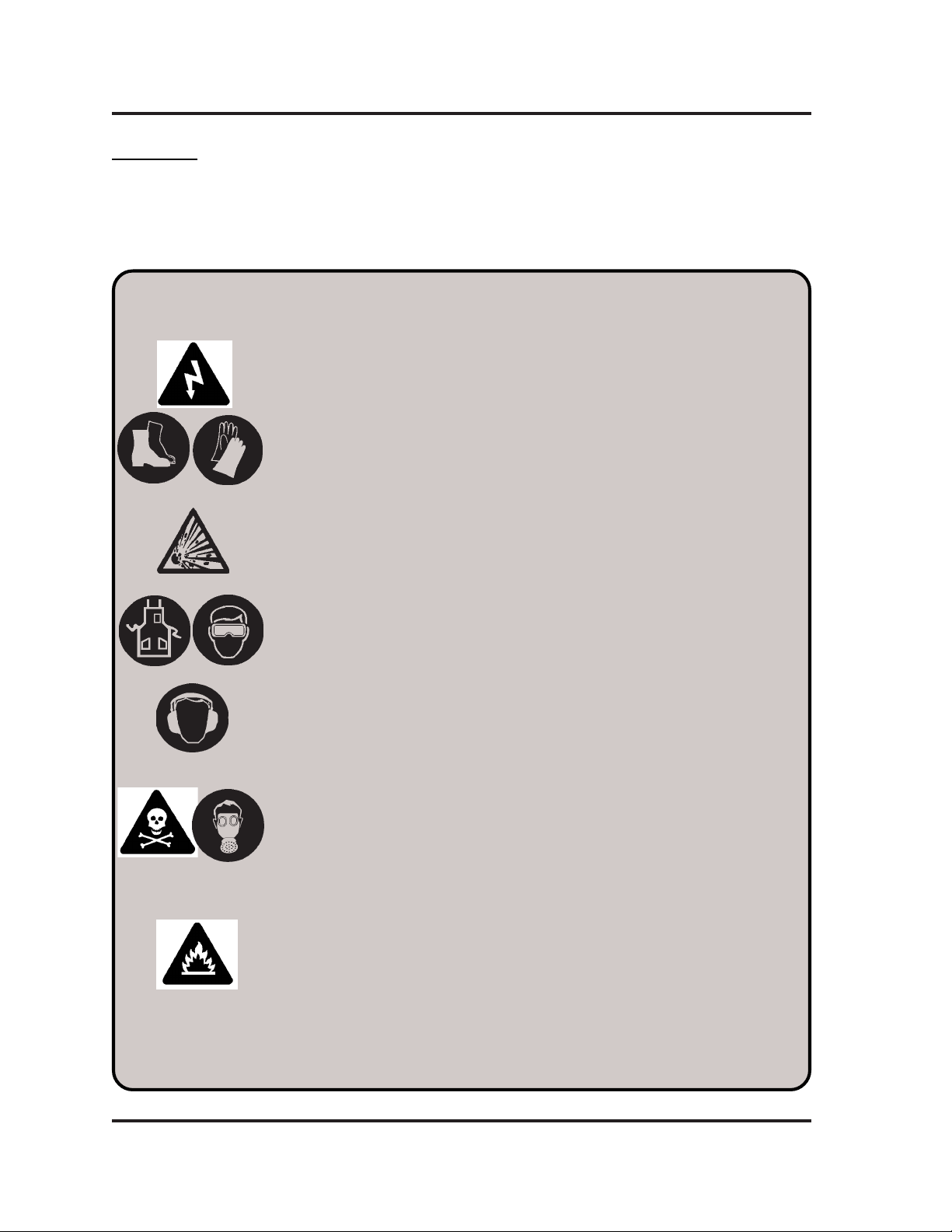
WARNING
ELECTRIC SHOCK CAN KILL.
• Do not touch live electrical parts.
• Keep all panels and covers in place when the water muffler system is
connected to a power source.
• Insulate yourself from work and ground: wear insulating gloves, shoes and
clothing.
• Keep gloves, shoes, clothing, work area, torch, and this machinery dry.
EXPLOSION WILL RESULT IF PRESSURIZED CONTAINERS ARE CUT.
ARC RAYS CAN INJURE EYES AND BURN SKIN.
• Wear correct eye and body protection.
NOISE CAN DAMAGE HEARING.
• Wear correct ear protection.
FUMES AND GASES CAN INJURE YOUR HEALTH.
• Keep your head out of the fumes.
• Provide ventilation, exhaust at the arc, or both to keep the fumes and
gases from your breathing zone and the general area.
• If ventilation is inadequate, use an approved respirator.
HEAT, SPLATTER AND SPARKS CAUSE FIRE AND BURNS.
• Do not cut near combustible material.
• Do not cut containers that have held combustibles.
• Do not have on your person any combustibles such as a butane lighter or
matches.
• Pilot arc can cause burns. Keep the torch nozzle away from yourself and
others when the switch is depressed.
• Wear correct eye and body protection.
Page 1-2
Air Injected Water Muffler System Instruction Manual
Page 10

SAFETY, INTRODUCTION & SPECIFICATIONS
INTRODUCTION
The Air Injected Water Muffler System is a plasma cutting torch option which greatly
improves the HT400 and HT4000/4001 plasma cutting systems safety and pollution
control capabilities. This water muffler system can be used to cut both above and
below water. The Air Injected Water Muffler System must be used in conjunction with
the Water Table Pollution Control System.
Above-Water Cutting
When used above water (material at the water line), the system becomes an effective
pollution control attachment which substantially reduces noise levels, ultraviolet
radiation, glare, and airborne particulates. Noise levels less than 86 dBA can be
expected when cutting with oxygen to a maximum current of 260A. Noise levels less
than 90 dBA can be expected when cutting with nitrogen to a maximum current of
400A. In addition, the water muffler improves cut quality by keeping the water table
water away from the cut zone and by continuously flushing the back of the workpiece
with air, preventing hydrogen from accumulating on the underside.
Underwater Cutting
When used underwater, the water muffler provides a water and air shield which
removes water from the cut zone, allowing for optimum operation of the plasma torch.
The water muffler greatly improves the quality of the cuts made underwater and
allows for cutting at the same speeds as above-water cutting. The continuous
flushing of the back of the workpiece with air, prevents hydrogen from accumulating.
Underwater operation also provides the maximum possible noise suppression over
the widest possible range of current levels. Less than 85 dBA can be expected for
both oxygen and nitrogen when cutting three inches or more below the surface of the
water.
System Components
Refer to
Installation,
Water Table Requirements
When cutting above water, the water level in the water table should be up to or
slightly above the bottom surface of the workpiece. The water reservoir located
beneath the plate prevents the high-intensity sound waves from escaping out from
the underside of the workpiece.
When the water muffler is used below water, the water level in the water table must
be three inches or more above the top surface of the workpiece.
Section 2,
Upon Receipt
, for a list of the system components.
The water muffler significantly cools the smoke and fumes generated by plasma
cutting (especially when cutting underwater). Proper ventilation and fume extraction
near the surface of the water table is required.
Air Injected Water Muffler System Instruction Manual
Page 1-3
5-95
Page 11

SAFETY, INTRODUCTION & SPECIFICATIONS
SPECIFICATIONS
Air Control Box (# 028298)
Input Power ................................................. 120 VAC
Input Air Pressure........................................ 80 -120 psi (5.5-8.3 bar) @ 20 scfm
(566 l/m) minimum
Weight ......................................................... 6 lbs. (2.7 kg)
Dimensions.................................................. 6-1/4" (159mm) (H) x 6-1/4" (159mm)
(W) x 4-1/4" (108mm) (D)
Pump* (# 031006, # 031088, # 031089)
Input Power:
# 031006 .................................................... Pump (3/4 DL) assembly with motor, 2
HP, 3500 RPM 230/460, 3 PH, 60 Hz
# 031088 .................................................... Pump (3/4 DL) assembly with motor, 2
HP, 3500 RPM 380-415V, 3 PH, 50 Hz
# 031089 .................................................... Pump (3/4 DL) assembly with motor, 2
HP, 3500 RPM 575V, 3 PH, 60 Hz
Maximum Working Pressure ....................... 100 psig (6.9 bar)
Duty ............................................................. Continuous
Direction of Rotation .................................... Clockwise (viewed from motor end)
Output.......................................................... 18-20 GPM
Weight ......................................................... 85 lbs. (38.6 kg) (includes base and
pump contactor box)
Dimensions.................................................. 19" (482mm) (H) x 11" (279mm) (W) x
17" (432mm) (D) (includes base and
pump contactor box)
* Refer to the Appendix for additional pump specifications.
Pump Contactor (# 003017)
Page 1-4
Contactor ..................................................... Size 00, 120 VAC Coil
Air Injected Water Muffler System Instruction Manual
Page 12

INSTALLATION
Section 2 Installation
In this section:
Upon Receipt ......................................................................................................... 2-2
Damage Claims...................................................................................................... 2-2
Installation .............................................................................................................. 2-3
Install Nozzle Assembly .................................................................................... 2-3
Install Pump ...................................................................................................... 2-3
Install Air Control Box ....................................................................................... 2-5
Installation Checkout ........................................................................................ 2-9
Pump Discharge Hose Water Recovery Checkout ........................................... 2-9
Install Check Valve ......................................................................................... 2-10
Air Injected Water Muffler System Instruction Manual
Page 2-1
Page 13

INSTALLATION
UPON RECEIPT
1. Remove the Air Injected Water Muffler System and save the carton. The carton
is reusable and provides an impact-resistant box for transporting or storing the
system and parts. The carton should contain one of the following systems:
034126 Water Muffler System 230/460V, 3 PH, 60 Hz w/Hoses
034127 Water Muffler System 230/460V, 3 PH, 60 Hz w/o Hoses
034128 Water Muffler System 380/415V, 3 PH, 60 Hz w/Hoses
034129 Water Muffler System 380/415V, 3 PH, 60 Hz w/o Hoses
034130 Water Muffler System 575V, 3 PH, 60 Hz w/Hoses
034131 Water Muffler System 575V, 3 PH, 60 Hz w/o Hoses
Refer to
tems listed above.
2. Verify that all components are present. Alert your distributor if any parts are
missing.
3. Inspect the water muffler components for any physical damage that may have
occurred during shipping. If there is evidence of damage, see the
Claims
Before operating the water muffler system, read the
this manual.
DAMAGE CLAIMS
Claims for damage during shipment - If any of the components were damaged
during shipment, you must file a claim with the carrier. Hypertherm will furnish you
with a bill of lading upon request. Call Customer Service at 1-800-643-0030.
Parts List, Section 4
section below.
, for a list of components which make up the sys-
Damage
Safety
and
Operation
sections of
Page 2-2
Air Injected Water Muffler System Instruction Manual
Page 14

INSTALLATION
To install the Air Injected Water Muffler System, you need to install and interconnect
the following units:
• Nozzle Assembly
• Pump Unit
• Air Control Box
Install Nozzle Assembly
The torch should be installed onto the cutting machine prior to installing the nozzle
assembly. If the torch has not been installed, refer to the applicable instruction
manual to do so.
Note: The nozzle assembly (# 034114 or # 034118) can be mounted onto the torch
with the water muffler retaining cap (# 020579) and consumables in place.
Prior to mounting the nozzle assembly, check the consumables (nozzle, swirl
ring, and electrode) and replace if necessary. Refer to the applicable
instruction manual for detailed information.
INSTALLATION
Install Pump
To install the nozzle assembly, refer to Figure 2-1 and proceed with following procedure.
1. Ensure the O-rings inside the nozzle assembly have been lightly coated with
silicone lubricant. Note that the water sleeve (# 034115) is already mounted in
the nozzle assembly.
2. Slide the nozzle assembly onto the torch and position the upper edge of the
nozzle assembly flush with where the torch and torch insulating sleeve meet.
Secure nozzle assembly to torch main body with clamping screw.
3. Slide the air deflector sleeve (# 034116) up inside the water sleeve until it seats.
The pump should be installed by an experienced electrician in compliance with
national/international electrical codes. Depending on the input power requirements,
pump motors are rated at 230/460 VAC, 3 phase, 60 Hz; 380/415 VAC, 3 phase, 50
Hz; and 575 VAC, 3 phase, 60 Hz. The pump motors are provided with overload
protection. The 230/460 VAC pumps are shipped from the factory wired for 460 VAC.
If 230 VAC operation is required, refer to the data tag on the pump to wire the motor
for 230 VAC operation. The wires are located in the box which next to the data tag.
To install and connect the pump, refer to Figures 2-2 and 2-3 and proceed as follows:
1. Place the pump within four feet (1.2 m) of the water table feed port to be used, if
hose is to be used. Longer hose distances can result in pump priming and water
Air Injected Water Muffler System Instruction Manual
Page 2-3
Page 15

INSTALLATION
Torch
Retaining Cap (# 020579)
Nozzle Assembly
with Adapters (# 034114) or
Nozzle Assembly
with Swivels (# 034118)
Water Sleeve (# 034115)
(already installed in nozzle
assembly)
Air Deflector Sleeve (# 034116)
Figure 2-1 Nozzle Assembly with Water Sleeve and Air Deflector Sleeve Installation
Page 2-4
Air Injected Water Muffler System Instruction Manual
Page 16

INSTALLATION
lag problems during startup, resulting in excessive noise and smoke during initial
starting. If more than four feet (1.2 m) of hose is required, it is recommended
that solid tubing be used up to a maximum length of eight feet (2.4 m). If solid
tubing is to be installed, do not use PTFE tape. Use liquid pipe-thread sealant
only.
The pump must be below the water level of the water table in order to function
properly.
2. Install the suction filter/strainer (# 027009) to the water table feed port. Figure
2-2 represents an optional installation; the user may wish to use another configuration. The reducer bushing (# 015578) and nipple (# 015509) are supplied;
other required filter/strainer connection and support hardware are customer
supplied.
3. Connect the pump inlet to the filter/strainer assembly using the supplied four-foot
hose assembly (# 024023) or solid tubing (eight feet [2.4 m] maximum). See
Figure 2-3.
4. Route the pump discharge hose assembly (# 024022) from the pump to the
nozzle assembly through the power track or festoon system. In no case should
the discharge hose be longer than 80 feet (24.4 m).
Note: If the discharge hose is routed in an overhead festoon system, a check
valve may be required. To determine if a check valve is needed, refer to
the
Pump Discharge Hose Water Recovery Checkout
section.
5. Connect three-conductor cable (# 023445, 50 ft. [15.3 m]) to the water muffler
pump contactor (AC and ground). Refer to Water Muffler/Pump Cable table
below.
6. Connect the plug end of the cable to the receptacle on the rear of the power
supply labled W-M PUMP.
Water Muffler/Pump Cable
From Power Supply
W-M Pump Recp/Plug
2
4
3
To W-M Pump
Contactor
Coil
AC Neutral
Ground
Color
Black
White
Green
at the back of this
AC Neutral
Function
W-M Coil
Ground
Install Air Control Box
1. Mount the air control box to a convient location on the cutting machine, so that it
is no farther than 10 feet (3 m) from the W-M nozzle assembly.
Air Injected Water Muffler System Instruction Manual
Page 2-5
8-94
Page 17

INSTALLATION
2. Route the AIR OUT hose assembly (# 024022) from the air control box to the
nozzle assembly through the power track or festoon system. In no case should
the discharge hose be longer than 10 feet (3 m). See Figure 2-3.
3. Route the air supply hose assembly from the shop air supply to the AIR IN fitting
on the air control box. The shop air supply must be clean, dry and oil free. It is
mandatory that the air supply be oil free, especially when using oxygen as the
plasma gas. The air supply must meet the following pressures and flow rate:
• 80 -120 psi (5.5-8.3 bar) delivery pressure
• 20 scfm (566 l/m) minimum flow rate
4. Route the five-conductor cable from the air control box to the receptacle on the
rear of the power supply labled W-M AIR. See Figure 2-3. Refer to Power
Supply/Air Control Box Cable table below.
Power Supply/Air Control Box Cable
From Power Supply
W-M Air Recp/Plug
11
12
13
14
6
To Air Control Box
Recp/Plug
1
2
3
4
5
Cable Part No.
023444
023624
023625
023626
023627
023628
Color
White
Black
Red
Brown
Green
Length (ft./m)
50/15.3
25/7.6
75/23
100/30.5
150/46
200/61
Function
W-M Hot
AC Neutral
Contactor Coil
W-M Coil
Ground
Page 2-6
8-94
Air Injected Water Muffler System Instruction Manual
Page 18

INSTALLATION
Minimum
Water Level
Filter/Strainer
# 027009
Customer
Supplied
1-3"
Remove Screw To
Clean Filter/Strainer
Nipple
# 015509
Reducer
Bushing
# 0155578
Hose Assembly
# 024023
Water Flow
To Pump
Water Table
Figure 2-2 Filter/Strainer, Optional Installation
Air Injected Water Muffler System Instruction Manual
Page 2-7
Page 19

INSTALLATION
PS/Air Control Box
Cable (5-Cond.)
(Refer to page 2-6 for
part numbers)
Detail of
Air Control Box
Connector Label Power Supply
W-M AIR 1X9 HT4000
W-M AIR 1X11 HT4001
WATER MUFFLER (W-M AIR)
11 RECP HT400
W-M PUMP 1X8 HT4000
W-M SUPPLY 1X10 HT4001
WATER SUPPLY (W-M PUMP)
12 RECP HT400
Power Supply
120 VAC Relay Power Cable
(# 023445 3-Cond.)
Pump Outlet Hose (# 024022)
Link Box
Pump
Contactor
Air Control Box
AIR IN Supply Hose
(Customer Supplied)
Input Power*
Pump Inlet Hose (# 024023)
AIR OUT Hose (# 024022)
Nozzle Assembly
SET
ON
OFF
Water Table
Input Power *
Detail of
Contactor Box
* 230/460V, 3 PH, 60 Hz
380/415V, 3 PH, 60 Hz
575V, 3 PH, 60 Hz
Figure 2-3 Air Injected Water Muffler System Interconnection Diagram
Page 2-8
Filter/Strainer
Notes:
The 240/480V water muffler pump is shipped to
120 VAC Relay Power
Cable
(# 023445 3-Cond.)
operate at 480V. The 380/415V pump is shipped to
operate at 380V. See tag on the pump to link for
alternate voltages. Link box is located on the pump
housing (see drawing).
The 240/480V and 380/415V pumps are shipped
Contactor
Heater Location
with two sets of 3 contactor heaters located in the
contactor box. See the chart below to determine
which heater to use.
Heater Hypertherm
Voltage Amps Label Part No.
240V (230V) 6.06 W45 003170
380V 3.00 W38 003029
415V 3.00 W38 003029
480V (460V) 3.00 W38 003029
600V (575V) 2.45 W36 003171
Air Injected Water Muffler System Instruction Manual
7-96
Page 20

Installation Checkout
After all power, air and water connections have been completed, test the Air Injected
Water Muffler System:
1. Ensure that the water table water level is high enough to feed the pump (covers
the filter intake completely).
2. Apply primary power to the power supply.
3. Apply shop air to the air control box. Inside the box, ensure the ON/OFF/SET
switch is to OFF.
4. Depress the green POWER ON switch to turn on the power supply.
5. In the air control box, momentarily position the ON/OFF/SET switch to SET and
then back to OFF.
Look for a clockwise pump rotation as viewed from the top of the motor. A
direction of rotation arrow is also shown on the side of the pump casing. If
the pump rotates in a counterclockwise direction, reverse any two of the 3phase power leads to the motor.
INSTALLATION
Caution: Operating the pump in reverse rotation will cause extensive
damage.
6. Inside the air control box, position the ON/OFF/SET switch to SET. With water
and air flowing, check the pressure gauge for 17 psig (1.2 bar) for above- water
cutting or 30 psig (2.0 bar) for underwater cutting. Adjust the pressure regulator,
if required.
7. Check for an even flow of water around the torch and for leaks around all
connections. Tighten connections as necessary. The water pump should deliver
approximately 18 to 20 gallons per minute.
8. Readjust the air pressure as performed in step 6, if required.
9. Position the ON/OFF/SET switch to ON. The system is now operational.
Pump Discharge Hose Water Recovery Checkout
If the pump discharge hose is routed through an overhead festoon system, a check
valve may be required. This can be determined by checking to see if the water from
the pump discharge hose drains back through the pump when the water muffler
system shuts off, and when the water muffler system restarts, the water does not
obtain full flow back to the water muffler before the plasma arc fires. If this condition
occurs, a check valve needs to be installed according to the procedure that follows.
Air Injected Water Muffler System Instruction Manual
Page 2-9
8-94
Page 21

INSTALLATION
Install Check Valve
Parts required:
• Valve, check, # 034156
• Gland, hose 3/4 NPT X #12 straight (2), # 015052
• Clamp, hose 3/4 - 1-3/4 (2), # 015234
Install the check valve in-line on the pump discharge hose as follows:
1. Cut the pump discharge hose (Fig 2-3) as close to the nozzle assembly as
possible to install the check valve. (The check valve should not be installed
farther than 6 feet (1.8 m) from the nozzle assembly.)
2. Apply liquid pipe sealant on to the threads ofboth glands. Screw glands into the
ends of the check valve and tighten with wrench.
3. Slide the hose clamps over the ends of the discharge hose. Then slide each end
of the hose over the ends of the check valve. Slide the hose clamps over the
ends of the check valve and tighten. (The arrow on the check valve indicates the
direction of water flow and should point in the direction of the nozzle assembly.)
4. Perform the
Installation Checkout
again to ensure proper water muffler operation.
Page 2-10
8-94
Air Injected Water Muffler System Instruction Manual
Page 22

OPERATION & MAINTENANCE
Section 3 Operation & Maintenance
In this section:
Operation ............................................................................................................... 3-2
Daily Setup and Operation................................................................................ 3-2
Above-Water Cutting ........................................................................................ 3-2
Underwater Cutting ........................................................................................... 3-3
Maintenance........................................................................................................... 3-3
Nozzle Assembly .............................................................................................. 3-3
Pump Unit ......................................................................................................... 3-4
Filter/Strainer .................................................................................................... 3-4
Pump Contactor ................................................................................................ 3-4
Air Control Box & Pump Contactor 120 VAC Control Signals .......................... 3-4
Technical Questions............................................................................................... 3-4
Air Injected Water Muffler System Instruction Manual
Page 3-1
Page 23

OPERATION & MAINTENANCE
OPERATION
The Air Injection Water Muffler System will start automatically with the initiation of the
start signal to the plasma cutting torch. The pump contactor coil and air solenoid
valve are energized simultaneously by a 120 VAC signal routed through the ON/OFF/
SET switch in the air control box from the power supply.
• When the switch is in the ON position, the 120 VAC signal will be supplied to the
pump contactor and air solenoid valve when the power supply main contactor is
activated.
• When the switch is in the SET position, the 120 VAC signal will be supplied to the
pump contactor and air solenoid valve. In this position, the air pressure values
are set. The power supply main contactor is not activated at this time.
• When the switch is in the OFF position, the water muffler system is disabled.
The operating procedures and requirements for above and underwater cutting are as
follows:
Daily Setup and Operation
1. Apply primary power to the power supply.
2. Apply shop air to the air control box. Inside the box, ensure the ON/OFF/SET
switch is to OFF.
3. Depress the green POWER ON switch to turn on the power supply.
4. Inside the air control box, position the ON/OFF/SET switch to SET. With water
and air flowing, check the pressure gauge for 17 psig @ 10 scfm (1.2 bar @ 283
l/m) for above- water cutting or 30 psig @ 20 scfm (2.0 bar @ 566 l/m) for
underwater cutting. Adjust the pressure regulator, if required.
5. Check for an even flow of water around the torch and for leaks around all
connections. Tighten connections as necessary. The water pump should deliver
approximately 18 to 20 gallons per minute.
6. Recheck the air pressure as performed in step 4, if required.
7. Position the ON/OFF/SET switch to ON. The system is now operational.
Above-Water Cutting
At the water table, ensure the water level is maintained at or slightly above the
bottom of the workpiece. Due to water muffler system pressure drops, the pressure
setting of 17 psig (1.2 bar) may be insufficient to supply the 10 scfm (283 l/m)
flowrate. If this is the case, increase the pressure until the proper flowrate has been
achieved.
Page 3-2
If initial height sensing (IHS) is not used, manual torch positioning will be necessary.
Air Injected Water Muffler System Instruction Manual
Page 24

This is done by lowering the torch to approximately 1/4-inch (6mm) above the top
surface of the workpiece.
Underwater Cutting
At the water table, ensure the water level is maintained at three inches or more
above the top surface of the workpiece. Due to water muffler system pressure drops,
the pressure setting of 30 psig (2.0 bar) may be insufficient to supply the 20 scfm
(566 l/m) flowrate. If this is the case, increase the pressure until the proper flowrate
has been achieved.
It is recommended that initial height sensing (IHS) be used when cutting under
water. If IHS is not used, manually position the torch as in above-water cutting.
MAINTENANCE
To maintain the Air Injected Water Muffler System, periodically inspect, clean, and
replace components as required. In the event the system does not work properly,
determine if the problem is air pressure, water pressure or if one or both of the 120
VAC control signals are missing.
OPERATION & MAINTENANCE
Nozzle Assembly
To inspect and clean the nozzle assembly, refer to Figure 2-1 and proceed as
follows:
1. Loosen the clamping screw securing the nozzle assembly or to the torch.
2. Pull the nozzle assembly (# 034114 or # 034118) with air deflector sleeve
(# 034116) and water sleeve (# 034115) off of torch.
3. Grasp the air deflector sleeve and simultaneously twist and pull to remove. With
a cloth wipe the bottom, sides and inside of sleeve.
4. Grasp the water sleeve and simultaneously twist and pull to remove. With a cloth
wipe the sides and inside of sleeve.
5. Apply a small amount of silicone grease to the O-rings inside the nozzle assem-
bly.
6. Slide the nozzle assembly onto the torch and position the upper edge of the
nozzle assembly flush with where the torch and torch insulating sleeve meet.
Secure nozzle assembly to torch main body with clamping screw.
7. Slide the water sleeve hole end first, up into the nozzle assembly until it seats.
8. Prior to positioning the air delflector sleeve check the consumables (nozzle, swirl
ring, and electrode) and replace if necessary. Refer to the applicable instruction
manual for detailed information.
9. Slide the air deflector sleeve up inside the water sleeve until it seats.
Air Injected Water Muffler System Instruction Manual
Page 3-3
Page 25

OPERATION & MAINTENANCE
Pump Unit
If the pump is faulty and requires maintenance, refer to the maintenance instructions
for the water muffler pump in the Appendix at the back of this manual. Pump maintenance also includes inspecting all hoses and connections and replacing as needed.
The suction filter/strainer should also be checked and cleaned periodically.
Filter/Strainer
The pump with 50 feet of 3/4-inch (15.3 m of 19mm) ID hose and the W-M nozzle
assembly should produce a flow of approximately 20 gallons per minute. A flow
lower than 18 gallons per minute reduces water muffler effectiveness. If this situation
occurs clean the filter/strainer in the water table.
To clean the suction filter/strainer, remove the screw and the plastic cover at the
bottom. See Figure 2-2. After cleaning the filter/strainer, replace the cover and
screw it back on.
Pump Contactor
If the pump contactor or 120 VAC relay coil is defective, contact an experienced
electrician to perform the maintenance.
Air Conrol Box & Pump Contactor 120 VAC Control Signals
If the 120 VAC control signal to air control box and/or pump contactor is missing,
refer to
instruction manual for the missing control signals.
Installation,
Section 2, Figure 2-3 and the wiring diagram of the applicable
TECHNICAL QUESTIONS
If you are unable to solve a problem after reviewing this manual, the applicable
instruction manual, and wiring diagram:
• Call your distributor. They will be able to help you, or refer you to an authorized
Hypertherm repair facility.
• If you need additional assistance, call our Field Service group at 1-800-643-9878.
Page 3-4
Air Injected Water Muffler System Instruction Manual
Page 26

PARTS LIST
Section 4 Parts List
In this section:
Water Muffler Systems ........................................................................................... 4-2
230/460V, 3 Ph, 60 Hz w/Hoses ....................................................................... 4-2
230/460V, 3 Ph, 60 Hz w/o Hoses .................................................................... 4-2
380-415V, 3 Ph, 50 Hz w/Hoses....................................................................... 4-3
380-415V, 3 Ph, 50 Hz w/o Hoses.................................................................... 4-3
575V, 3 Ph, 60 Hz w/Hoses .............................................................................. 4-4
575V, 3 Ph, 60 Hz w/o Hoses ........................................................................... 4-4
Nozzle Assembly with Adapters ............................................................................. 4-5
Nozzle Assembly with Swivels ............................................................................... 4-6
Water Supply Assembly ......................................................................................... 4-7
Pump Assembly ..................................................................................................... 4-9
Pump Discharge Hose Check Valve (Optional) ..................................................... 4-9
Air Injected Water Muffler System Instruction Manual
Page 4-1
Page 27

PARTS LIST
WATER MUFFLER SYSTEMS
230/460V, 3 Ph, 60 Hz w/Hoses (# 034126)
Part Number Description Quantity
024022 Hose assembly, #12 x 50 ft. with: 1
015262 Swivel, #12 3/4 Syn hose Brs (attached to hose) 2
015264 Ferrule, 1.150 ID x .88 Brs (attached to hose) 2
024023 Hose assembly, #12 x 4 ft. with: 1
015262 Swivel, #12 3/4 Syn hose Brs (attached to hose) 1
015264 Ferrule, 1.150 ID x .88 Brs (attached to hose) 1
015052 Adapter, 3/4 NPT x #12 (attached to hose) 1
027009 Filter, 2" NPT, water 1
015578 Reducer bushing, 2" x 3/4", galv 1
015509 Nipple 2" x CL, galv 1
027055 Silicone lubricant 1
025031 O-ring kit 1
008212 Strain relief, 1/2 NPT X .197 -.354 2
015012 Adapter, 1/4 NPT x # 6 1
015013 Swivel, # 6 4
023444 Cable, W-M air control, 50 ft. 1
023445 Cable, W-M pump contactor, 50 ft. 1
028298 Air control box 1
028042 Water supply, W-M (refer to page 4-7) 1
034114* Nozzle assembly, W-M, with adapters (refer to page 4-5) 1
034118* Nozzle assembly, W-M, with swivels (refer to page 4-6) 1
020579 Cap, HT400/PAC170 taper nozzle retaining 1
046016 Hose, 3/8" ID Blk 60 ft.
230/460V, 3 Ph, 60 Hz w/o Hoses (# 034127)
Part Number Description Quantity
015262 Swivel, #12 3/4 Syn hose Brs 3
015264 Ferrule, 1.150 ID x .88 Brs 3
015052 Adapter, 3/4 NPT x #12 1
015578 Reducer bushing, 2" x 3/4", galv 1
015509 Nipple 2" x CL, galv 1
027009 Filter, 2" NPT, water 1
027055 Silicone lubricant 1
025031 O-ring kit 1
008212 Strain relief, 1/2 NPT X .197 -.354 2
015012 Adapter, 1/4 NPT x # 6 1
015013 Swivel, # 6 4
023444 Cable, W-M air control, 50 ft. 1
023445 Cable, W-M pump contactor, 50 ft. 1
028298 Air control box 1
028042 Water supply, W-M (refer to page 4-7) 1
034114* Nozzle assembly, W-M, with adapters (refer to page 4-5) 1
034118* Nozzle assembly, W-M, with swivels (refer to page 4-6) 1
020579 Cap, HT400/PAC170 taper nozzle retaining 1
* The water muffler systems come with either the 034114 or 034118 nozzle assembly.
Page 4-2 Air Injected Water Muffler System Instruction Manual
8-94
Page 28

380-415V, 3 PH, 50 Hz w/Hoses (# 034128)
Part Number Description Quantity
024022 Hose assembly, #12 x 50 ft. with: 1
015262 Swivel, #12 3/4 Syn hose Brs (attached to hose) 2
015264 Ferrule, 1.150 ID x .88 Brs (attached to hose) 2
024023 Hose assembly, #12 x 4 ft. with: 1
015262 Swivel, #12 3/4 Syn hose Brs (attached to hose) 1
015264 Ferrule, 1.150 ID x .88 Brs (attached to hose) 1
015052 Adapter, 3/4 NPT x #12 (attached to hose) 1
027009 Filter, 2" NPT, water 1
015578 Reducer bushing, 2" x 3/4", galv 1
015509 Nipple 2" x CL, galv 1
027055 Silicone lubricant 1
025031 O-ring kit 1
008212 Strain relief, 1/2 NPT X .197 -.354 2
015012 Adapter, 1/4 NPT x # 6 1
015013 Swivel, # 6 4
023444 Cable, W-M air control, 50 ft. 1
023445 Cable, W-M pump contactor, 50 ft. 1
028298 Air control box 1
028299 Water supply, W-M (refer to page 4-7) 1
034114* Nozzle assembly, W-M, with adapters (refer to page 4-5) 1
034118* Nozzle assembly, W-M, with swivels (refer to page 4-6) 1
020579 Cap, HT400/PAC170 taper nozzle retaining 1
046016 Hose, 3/8" ID Blk 60 ft.
PARTS LIST
380-415V, 3 PH, 50 Hz w/o Hoses (# 034129)
Part Number Description Quantity
015262 Swivel, #12 3/4 Syn hose Brs 3
015264 Ferrule, 1.150 ID x .88 Brs 3
015052 Adapter, 3/4 NPT x #12 1
015578 Reducer bushing, 2" x 3/4", galv 1
015509 Nipple 2" x CL, galv 1
027009 Filter, 2" NPT, water 1
027055 Silicone lubricant 1
025031 O-ring kit 1
008212 Strain relief, 1/2 NPT X .197 -.354 2
015012 Adapter, 1/4 NPT x # 6 1
015013 Swivel, # 6 4
023444 Cable, W-M air control, 50 ft. 1
023445 Cable, W-M pump contactor, 50 ft. 1
028298 Air control box 1
028299 Water supply, W-M (refer to page 4-7) 1
034114* Nozzle assembly, W-M, with adapters (refer to page 4-5) 1
034118* Nozzle assembly, W-M, with swivels (refer to page 4-6) 1
020579 Cap, HT400/PAC170 taper nozzle retaining 1
* The water muffler systems come with either the 034114 or 034118 nozzle
assembly.
Air Injected Water Muffler System Instruction Manual
Page 4-3
8-94
Page 29

PARTS LIST
575V, 3 Ph, 60 Hz w/Hoses (# 034130)
Part Number Description Quantity
024022 Hose assembly, #12 x 50 ft. with: 1
015262 Swivel, #12 3/4 Syn hose Brs (attached to hose) 2
015264 Ferrule, 1.150 ID x .88 Brs (attached to hose) 2
024023 Hose assembly, #12 x 4 ft. with: 1
015262 Swivel, #12 3/4 Syn hose Brs (attached to hose) 1
015264 Ferrule, 1.150 ID x .88 Brs (attached to hose) 1
015052 Adapter, 3/4 NPT x #12 (attached to hose) 1
027009 Filter, 2" NPT, water 1
015578 Reducer bushing, 2" x 3/4", galv 1
015509 Nipple 2" x CL, galv 1
027055 Silicone lubricant 1
025031 O-ring kit 1
008212 Strain relief, 1/2 NPT X .197 -.354 2
015012 Adapter, 1/4 NPT x # 6 1
015013 Swivel, # 6 4
023444 Cable, W-M air control, 50 ft. 1
023445 Cable, W-M pump contactor, 50 ft. 1
028298 Air control box 1
028308 Water supply, W-M (refer to page 4-7) 1
034114* Nozzle assembly, W-M, with adapters (refer to page 4-5) 1
034118* Nozzle assembly, W-M, with swivels (refer to page 4-6) 1
020579 Cap, HT400/PAC170 taper nozzle retaining 1
046016 Hose, 3/8" ID Blk 60 ft.
575V, 3 Ph, 60 Hz w/o Hoses (# 034131)
Part Number Description Quantity
015262 Swivel, #12 3/4 Syn hose Brs 3
015264 Ferrule, 1.150 ID x .88 Brs 3
015052 Adapter, 3/4 NPT x #12 1
015578 Reducer bushing, 2" x 3/4", galv 1
015509 Nipple 2" x CL, galv 1
027009 Filter, 2" NPT, water 1
027055 Silicone lubricant 1
025031 O-ring kit 1
008212 Strain relief, 1/2 NPT X .197 -.354 2
015012 Adapter, 1/4 NPT x # 6 1
015013 Swivel, # 6 4
023444 Cable, W-M air control, 50 ft. 1
023445 Cable, W-M pump contactor, 50 ft. 1
028298 Air control box 1
028308 Water supply, W-M (refer to page 4-7) 1
034114* Nozzle assembly, W-M, with adapters (refer to page 4-5) 1
034118* Nozzle assembly, W-M, with swivels (refer to page 4-6) 1
020579 Cap, HT400/PAC170 taper nozzle retaining 1
* The water muffler systems come with either the 034114 or 034118 nozzle
assembly.
Page 4-4 Air Injected Water Muffler System Instruction Manual
8-94
Page 30

NOZZLE ASSEMBLY WITH ADAPTERS
Part No. - 034114
Part
Number Description Quantity
034114 Nozzle assembly with adapters 1
034115 Water sleeve 1
034116 Air deflector sleeve 1
044036 O-ring 2
044139 O-ring 2
044226 O-ring 1
Torch
PARTS LIST
Nozzle assembly
with adapters
O-Ring 044226
O-Rings 044139
O-Rings 044036
Water Sleeve
Air Deflector
Sleeve
Figure 4-1 Nozzle Assembly with Adapters
Air Injected Water Muffler System Instruction Manual
Page 4-5
Page 31

PARTS LIST
NOZZLE ASSEMBLY WITH SWIVELS
Part No. - 034118
Part
Number Description Quantity
034118 Nozzle assembly with swivels 1
034115 Water sleeve 1
034116 Air deflector sleeve 1
044036 O-ring 2
044139 O-ring 2
044226 O-ring 1
Torch
Nozzle assembly
with swivels
O-Ring 044226
O-Rings 044139
O-Rings 044036
Water Sleeve
Air Deflector
Sleeve
Figure 4-2 Nozzle Assembly with Swivels
Page 4-6 Air Injected Water Muffler System Instruction Manual
Page 32

WATER SUPPLY ASSEMBLY (FIG 4-3)
Stock No. - 028042 — 240/480V, 3PH, 60 HZ
Stock No. - 028299 — 380-415V, 3PH, 50 Hz
Stock
Number Description Item Quantity
031006 Pump (3/4 DL) assembly with motor, 2 HP, 1 1
or 3500 RPM 230-460 VAC, 3 phase
031088 Pump (3/4DL) assembly with motor, 2 HP, 1 1
3500 RPM 380-415 VAC, 3 phase
015051 Adapter, 3/4 NPT x #12 2 2
004437 Base, water supply W-M 3 1
008045 Fitting, conduit elbow, 1/2 x 1/2 4 1
008047 Strain relief, 1/2 x .250-.375 5 1
003017 Contactor, size 00,120 VAC coil; 6 1
003029 Heater:003017 Cntor 3.00A -W38 3
003170 Heater:003017 Cntor 6.06A -W45 3
034006 Contactor mounting bracket 7 1
046011 Conduit,1/2" sealtite flexible 8 6 "
008044 Fitting, conduit straight, 1/2 x 1/2 9 1
PARTS LIST
Stock No. - 028308 — 600V, 3PH, 60 Hz
Stock
Number Description Item Quantity
031089 Pump (3/4 DL) assembly with motor, 2 HP, 1 1
3500 RPM 575 VAC, 3 phase
015051 Adapter, 3/4 NPT x #12 2 2
004437 Base, water supply W-M 3 1
008045 Fitting, conduit elbow, 1/2 x 1/2 4 1
008047 Strain relief, 1/2 x .250-.375 5 1
003017 Contactor, size 00,120 VAC coil; 6 1
003171 Heater:003017 Cntor 2.45A -W36 3
034006 Contactor mounting bracket 7 1
046011 Conduit,1/2" sealtite flexible 8 6 "
008044 Fitting, conduit straight, 1/2 x 1/2 9 1
Air Injected Water Muffler System Instruction Manual
Page 4-7
6-96
Page 33

PARTS LIST
1
8
7
2
6
2
3
4
5
Figure 4-3 Water Supply Assembly
Page 4-8 Air Injected Water Muffler System Instruction Manual
Page 34

PUMP ASSEMBLY (SEE APPENDIX)
Part No. - 031049
Part
Number Description Item Quantity
031036 Impeller, 1285505 3 1
031047 Casing, 1326505 5 1
* Casing cap screw 5D 8
031035 Adapter cradle, 1250705 7 1
* Adapter Cap Screws 7G 1
031048 Backhead, 1080280 22 1
031040 Clearance shim, 9157206-7-8 37 3
031041 Casing gasket, 9155333 77 1
031042 Stationary seal element, 6960440 95A 1
Rotating seal face, 6960440 95B 1
* Obtain locally
PARTS LIST
PUMP DISCHARGE HOSE CHECK VALVE (OPTIONAL)*
Part
Number Description Quantity
034156 Valve, check 1
015052 Gland, hose 3/4 NPT x #12 straight 2
015234 Clamp, hose 3/4 to 1-3/4 inch 2
* Refer to Section 2,
and check valve installation information.
Installation
for pump discharge hose water recovery checkout
Air Injected Water Muffler System Instruction Manual
Page 4-9
8-94
Page 35

APPENDIX
APPENDIX
In this section:
Water Muffler Pumps ............................................................................................. a-2
Air Injected Water Muffler System Instruction Manual
Page a-1
Page 36

a-2
Page 37

a-3
Page 38

a-4
Page 39

a-5
Page 40

a-6
 Loading...