


HT2000 /
MAX200
Water
Muffler
Instruction Manual
802050 - Rev. 4

HT2000 /MAX200
Water Muffler
Instruction Manual
(P/N 802050)
Revision 4 October, 2013
HYPERTHERM, Inc.
P.O. Box 5010
Hanover, New Hampshire 03755-5010
Tel.: (603) 643-3441
Fax: (603) 643-5352
http://www.hypertherm.com
email:info@hypertherm.com
© Copyright 2013 Hypertherm, Inc.
All Rights Reserved
Hypertherm, HyDefinition, HT, HyLife, LongLife, MAX, PAC and Powermax are trademarks of Hypertherm, Inc.,
and may be registered in the United States and/or other countries

Hypertherm, Inc.
Etna Road, P.O. Box 5010
Hanover, NH 03755 USA
603-643-3441 Tel (Main Office)
603-643-5352 Fax (All Departments)
800-643-9878 Tel (Technical Service)
800-737-2978 Tel (Customer Service)
Hypertherm Automation
5 Technology Drive
West Lebanon, NH 03755 USA
603-298-7970 Tel
603-298-7977 Fax
Hypertherm Plasmatechnik GmbH
Technologiepark Hanau
Rodenbacher Chaussee 6
63457 Hanau-Wolfgang, Deutschland
49 6181 58 2100 Tel
49 6181 58 2134 Fax
49 6181 58 2123 (Technical Service)
Hypertherm Singapore Pte Ltd
No. 19 Kaki Bukit Road 2
K.B. Warehouse Complex
Singapore 417847, Republic of Singapore
65 841 2489 Tel
65 841 2490 Fax
65 841 2489 (Technical Service)
Japan
1952-14 Yata-Natsumegi
Mishima City, Shizuoka Pref.
411-0801 Japan
81 0 559 75 7387 Tel
81 0 559 75 7376 Fax
Hypertherm UK Ltd
9 Berkeley Court, Manor Park
Runcorn, Cheshire, England WA7 1TQ
44 1928 579 074 Tel
44 1928 579 604 Fax
France
15 Impasse des Rosiers
95610 Eragny, France
0805 050 111 Tel
0805 050 222 Fax
Hypertherm S.r.L.
Via Torino 2
20123 Milano, Italia
39 02 725 46 312 Tel
39 02 725 46 400 Fax
39 02 725 46 314 (Technical Service)
Hypertherm B.V.
Burg. Haverkampstraat 13
7091 CN Dinxperlo, Nederland
31 315 655866 Tel
31 315 655886 Fax
Hypertherm B.V. (ETSO)
Vaartveld 9
4704 SE Roosendaal, Nederland
00 800 49 73 7843 – toll-free in Europa
31 165 596900 Tel
31 165 596901 Fax
Hypertherm Brasil Ltda.
Rua Visconde de Santa Isabel, 20 – Sala 611
Vila Isabel, RJ
Brasil CEP 20560-120
55 21 2278 6162 Tel
55 21 2578 0947 Fax
10/30/01

TABLE OF CONTENTS
SECTION 1 SAFETY, INTRODUCTION & SPECIFICATIONS.................................................... 1-1
Safety ................................................................................................................................................ 1-2
Introduction ....................................................................................................................................... 1-3
Above-Water Cutting .................................................................................................................. 1-3
Underwater Cutting ..................................................................................................................... 1-3
System Components .................................................................................................................. 1-3
Water Table Requirements......................................................................................................... 1-3
Specifications .................................................................................................................................... 1-4
SECTION 2 INSTALLATION ......................................................................................................... 2-1
Upon Receipt .................................................................................................................................... 2-2
HT2000/MAX200 Water Muffler System with Hoses .................................................................. 2-2
HT2000/MAX200 Water Muffler System without Hoses ............................................................. 2-2
Damage Claims .......................................................................................................................... 2-3
Installation ......................................................................................................................................... 2-3
Install the Nozzle Assembly ........................................................................................................ 2-3
Position and Connect the Pump to the Water Table .................................................................. 2-6
Connect the Pump to the Nozzle Assembly ............................................................................... 2-6
Connect the Pump to the HT2000 .............................................................................................. 2-6
Connect the Pump to the MAX200 ............................................................................................. 2-9
Test the System.......................................................................................................................... 2-9
Pump Discharge Hose Water Recovery Checkout................................................................... 2-10
Install Check Valve ................................................................................................................... 2-10
SECTION 3 OPERATION & MAINTENANCE............................................................................... 3-1
Operation .......................................................................................................................................... 3-2
Above-Water Cutting/Underwater Cutting .................................................................................. 3-2
Maintenance...................................................................................................................................... 3-3
Pump Unit ................................................................................................................................... 3-3
Suction Filter/Strainer ................................................................................................................. 3-3
Pump Contactor.......................................................................................................................... 3-3
Pump Contactor 120VAC Control Signal .................................................................................... 3-3
Nozzle Assembly ........................................................................................................................ 3-3
Removal and Replacement Procedures ........................................................................................... 3-4
Remove the Nozzle Assembly from the Torch ........................................................................... 3-4
Disassemble the Nozzle Assembly ............................................................................................ 3-5
Replace the Nozzle Assembly .................................................................................................... 3-6
Technical Questions.......................................................................................................................... 3-6
SECTION 4 STANDARD COMPONENTS .................................................................................... 4-1
Water Muffler System 240/480V, 3PH, 60 Hz w/Hoses .................................................................... 4-2
Water Muffler System 240/480V, 3PH, 60 Hz w/o Hoses ................................................................. 4-2
Water Muffler System 380-415V, 3PH, 50 Hz w/Hoses .................................................................... 4-3
HT2000/MAX200 Water Muffler Instruction Manual
Page i

TABLE OF CONTENTS
Water Muffler System 380-415V, 3PH, 50 Hz w/o Hoses ................................................................. 4-3
Water Muffler System 600V, 3PH, 60 Hz w/Hoses ........................................................................... 4-4
Water Muffler System 600V, 3PH, 60 Hz w/o Hoses ........................................................................ 4-4
Nozzle Assembly, W-M, HT2000/MAX200 ....................................................................................... 4-5
Water Supply, W-M, HT2000/MAX200 ............................................................................................. 4-6
Water Muffler Pump Assembly.......................................................................................................... 4-7
HT2000 Water Muffler Pump Cable .................................................................................................. 4-8
Pump Discharge Hose Check Valve (Optional) ................................................................................ 4-8
APPENDIX ........................................................................................................................................ a-1
Water Muffler Pumps ........................................................................................................................ a-2
ILLUSTRATIONS
Figure 2-1 Nozzle Assembly Installation .................................................................................. 2-5
Figure 2-2 Suction/Filter Strainer, Optional Installation ............................................................ 2-7
Figure 2-3 Water Muffler System Interconnection Diagram ..................................................... 2-8
Figure 3-1 Nozzle Assembly Removal and Replacement ........................................................ 3-4
Figure 3-2 Assemble/Disassemble the Nozzle Assembly ........................................................ 3-5
Figure 4-1 Nozzle Assembly..................................................................................................... 4-5
Figure 4-2 Water Supply Assembly .......................................................................................... 4-7
Figure 4-3 HT2000 Water Muffler Pump Cable - PS to WM..................................................... 4-8
Page ii
HT2000/MAX200 Water Muffler Instruction Manual

SAFETY, INTRODUCTION & SPECIFICATIONS
Section 1
Safety, Introduction & Specifications
In this section:
Safety ..................................................................................................................... 1-2
Introduction ............................................................................................................ 1-3
Above-Water Cutting ........................................................................................ 1-3
Underwater Cutting ........................................................................................... 1-3
System Components ........................................................................................ 1-3
Water Table Requirements ............................................................................... 1-3
Specifications ......................................................................................................... 1-4
HT2000/MAX200 Water Muffler Instruction Manual
Page 1-1
SAFETY, INTRODUCTION & SPECIFICATIONS
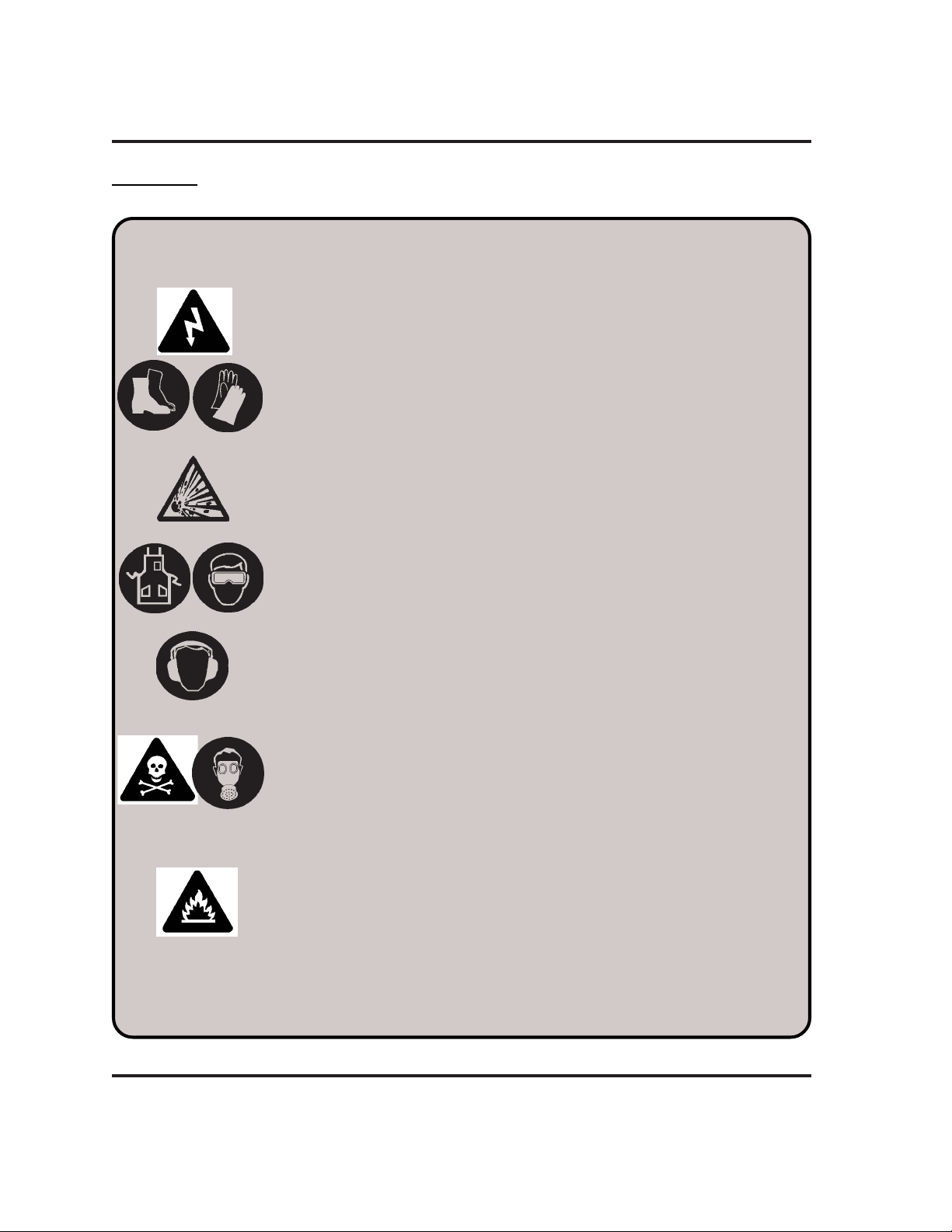
SAFETY
WARNING
ELECTRIC SHOCK CAN KILL.
• Do not touch live electrical parts.
• Keep all panels and covers in place when the machine is connected to a
power source.
• Insulate yourself from work and ground: wear insulating gloves, shoes and
clothing.
• Keep gloves, shoes, clothing, work area, torch, and this machinery dry.
EXPLOSION WILL RESULT IF PRESSURIZED CONTAINERS ARE CUT.
ARC RAYS CAN INJURE EYES AND BURN SKIN.
• Wear correct eye and body protection.
Page 1-2
NOISE CAN DAMAGE HEARING.
• Wear correct ear protection.
FUMES AND GASES CAN INJURE YOUR HEALTH.
• Keep your head out of the fumes.
• Provide ventilation, exhaust at the arc, or both to keep the fumes and
gases from your breathing zone and the general area.
• If ventilation is inadequate, use an approved respirator.
HEAT, SPLATTER AND SPARKS CAUSE FIRE AND BURNS.
• Do not cut near combustible material.
• Do not cut containers that have held combustibles.
• Do not have on your person any combustibles such as a butane lighter or
matches.
• Pilot arc can cause burns. Keep the torch nozzle away from yourself and
others when the switch is depressed.
• Wear correct eye and body protection.
HT2000/MAX200 Water Muffler Instruction Manual

INTRODUCTION
The HT2000/MAX200 Water Muffler is a plasma cutting torch option which greatly
improves the plasma cutting system's safety and pollution control capabilities. The
Water Muffler system can be used to cut both above and below water.
Above-Water Cutting
When used above water (material at the water line), the system becomes an effective
pollution control attachment which substantially reduces noise levels, ultraviolet
radiation, glare, and airborne particulates. Noise levels less than 95 dBA can be
expected when cutting with oxygen to a maximum current of 200A.
Underwater Cutting
Underwater operation provides the maximum possible noise suppression over the
widest possible range of current levels. Less than 70 dBA can be expected when
cutting three inches or more below the surface of the water.
SAFETY, INTRODUCTION & SPECIFICATIONS
System Components
Refer to the
Water Muffler System components.
Installation
Water Table Requirements
The Water Muffler must be used in conjunction with the Water Table Pollution Control
System. When cutting above water, the water level in the Water Table should be up
to or slightly above the bottom surface of the workpiece. The water reservoir located
beneath the plate prevents the high-intensity sound waves from escaping out the
underside of the workpiece.
When the Water Muffler is used below water, the water level in the Water Table must
be three inches or more above the top surface of the workpiece.
The Water Muffler System significantly cools the smoke and fumes generated by
plasma cutting (especially when cutting underwater). Proper ventilation and fume
extraction near the surface of the Water Table is required.
section,
Upon Receipt
, for a list of the HT2000/MAX200
HT2000/MAX200 Water Muffler Instruction Manual
Page 1-3

SAFETY, INTRODUCTION & SPECIFICATIONS
SPECIFICATIONS
Pump*
I
nput Power:
# 031006 .................................................... Pump (3/4 DL) assembly with motor, 2
# 031088 .................................................... Pump (3/4 DL) assembly with motor,
# 031089 .................................................... Pump (3/4 DL) assembly with motor,
Maximum Working Pressure .................... 100 psig
Duty ............................................................ Continuous
Direction of Rotation ................................. Clockwise (viewed from motor end)
HP, 3500 RPM 240/480, 3 PH, 60 Hz
2HP, 3500 RPM 380-415V, 3 PH, 50 Hz
2HP, 3500 RPM 600V, 3 PH, 60 Hz
Output ......................................................... 9-11 GPM
Weight ........................................................ 85 lbs. (includes base and pump
Dimensions ................................................ 19" (H) x 11" (W) x 17" (D) (includes
* Refer to the Appendix for additional pump specifications.
Pump Contactor
# 003017 ..................................................... Contactor, Size 00, 120 VAC
contactor box)
base and pump contactor box)
Page 1-4
HT2000/MAX200 Water Muffler Instruction Manual

INSTALLATION
Section 2
Installation
In this section:
Upon Receipt ......................................................................................................... 2-2
HT2000/MAX200 Water Muffler System with Hoses ........................................ 2-2
HT2000/MAX200 Water Muffler System without Hoses ................................... 2-2
Damage Claims ................................................................................................ 2-3
Installation .............................................................................................................. 2-3
Install the Nozzle Assembly .............................................................................. 2-3
Position and Connect the Pump to the Water Table......................................... 2-6
Connect the Pump to the Nozzle Assembly ..................................................... 2-6
Connect the Pump to the HT2000 .................................................................... 2-6
Connect the Pump to the MAX200 ................................................................... 2-9
Test the System ................................................................................................ 2-9
Pump Discharge Hose Water Recovery Checkout ......................................... 2-10
Install Check Valve ......................................................................................... 2-10
HT2000/MAX200 Water Muffler Instruction Manual
Page 2-1

INSTALLATION
UPON RECEIPT
1. Remove the Water Muffler system and save the carton. The carton is reusable and
provides an impact-resistant box for transporting or storing the system and parts. The
carton should include either of the following systems:
HT2000/MAX200 Water Muffler System with Hoses
020423 Cap, HT2000/MAX200 shield
024022 Hose assembly, #12 x 50 ft. with:
015262 Swivel, #12 3/4 Syn hose Brs (attached to hose)(2)
015262 Ferrule, 1.150 ID x .88 Brs (attached to hose)(2)
046020 Hose:3/4" ID Blk
024023 Hose assembly, #12 x 4 ft. with:
015262 Swivel, #12 3/4 Syn hose Brs (attached to hose)(2)
015262 Ferrule, 1.150 ID x .88 Brs (attached to hose)(2)
015052 Adapter, 3/4 NPT x #12 (attached to hose)
027009 Filter, 2" NPT, water
015578 Reducer bushing, 2" x 3/4", galv
015509 Nipple 2" x CL, galv
046020 Hose:3/4" ID Blk
027012 Silicone lubricant
028042 Water supply, W-M, 240/480V, 3PH, 60 Hz (refer to page 4-6)
or
028299 Water supply, W-M, 380-415V, 3PH, 60 Hz (refer to page 4-6)
or
028308 Water supply, W-M, 600V, 3PH, 60 Hz (refer to page 4-6)
034148 Nozzle assembly, W-M, HT2000/MAX200 (refer to page 4-5)
020566 Shield, HT2000/MAX200 W-M
020618 Shield, HT2000/MAX200 W-M - 100 Amp
HT2000/MAX200 Water Muffler System without Hoses
020423 Cap, HT2000/MAX200 shield
015053 Swivel, #12 (3)
015052 Adapter, 3/4 NPT x #12
027009 Filter, 2" NPT, water
015578 Reducer bushing, 2" x 3/4", galv
015509 Nipple 2" x CL, galv
027012 Silicone lubricant
028042 Water supply, W-M, 240/480V, 3PH, 60 Hz (refer to page 4-6)
or
028299 Water supply, W-M, 380-415V, 3PH, 60 Hz (refer to page 4-6)
or
028308 Water supply, W-M, 600V, 3PH, 60 Hz (refer to page 4-6)
034148 Nozzle assembly, W-M, HT2000/MAX200 (refer to page 4-5)
020566 Shield, HT2000/MAX200 W-M
020618 Shield, HT2000/MAX200 W-M - 100 Amp
Page 2-2
5-95
HT2000/MAX200 Water Muffler Instruction Manual

INSTALLATION
2. Verify that all components are present. Alert your distributor if any parts are
missing.
3. Inspect the power supply for any physical damage that may have occurred during
shipping. If there is evidence of damage, see the
Damage Claims
section below.
Before operating the Water Muffler system, read the
this manual.
Damage Claims
Claims for damage during shipment - If your unit was damaged during shipment,
you must file a claim with the carrier. Hypertherm will furnish you with a bill of lading
upon request. Call our Customer Service group at 1-800-643-0030.
INSTALLATION
To install the HT2000/MAX200 Water Muffler System, you need to install and
interconnect the following units:
• Nozzle Assembly
• Pump Unit
Turn all power to the HT2000 or MAX200 OFF before installing water muffler!
WARNING
Safety
and
Operation
sections of
Install the Nozzle Assembly
It is not necessary to disconnect the torch leads from the torch to install the HT2000/
MAX200 water muffler nozzle assembly:
1. Turn power to the HT2000 or MAX200 power supply OFF.
2. Remove the shield and shield cap from the HT2000 or MAX200 machine torch.
3. Select correct consumables for cutting with the water muffler system (see chart
on following page) and replace, if necessary, all torch consumables except the
W-M shield and shield cap.
For further cut chart information, refer to instruction manuals #802070: HT2000
Instruction, or #800980: MAX200 Machine Torch, or #800990: MAX200 Remote
High Frequency.
HT2000/MAX200 Water Muffler Instruction Manual
Page 2-3
 Loading...